

GSD i70 Installation Manual

Technical Specification
Operation Instructions
2
Installation Diagrams
4
Contents
3
Technical specification
Name of manufacturer
Description of equipment
Standards
Security grade
Environmental class
Operating temperature
Relative humidity
Functions
Inputs
Signals / Indications
Dimensions (w d h)
Power supply description
Battery
GSDi-RF-RPT
Global Security Devices Ltd
RF Repeater
EN50131-1:2006
EN50131-2-2:2009
EN50131-6:2008
PD6662:2010
EN60950:2006
Grade 2
Class II
-10ºC to 40ºC
Up to 75% non-condensing
Enclosure tamper detection
Removal from mounting tamper detection
Battery voltage monitor
None
Condition Signal
Tamper Tamper
Low battery Low battery fault
Total supply loss Loss of communication
68mm 48mm 130mm
8V to 14V
1 x ICR123 LI-ion 750 mA rechargeable battery.
Nominal voltage 3.7V. Low voltage indication
below 2.6V. Life typically > 30 hours backup
YOUR SECURITY IS OUR PRIORITY
Installation Manual V1.00
Global Security Devices Ltd: No.3 Broomhill Business Complex, Tallaght,
Dublin 24, Ireland, Phone: +353 (1) 524 2691, Email: info@globalsecurity.ie
www.globalsecurity.ie
Grade 2 Intrusion RF Repeater
i 70
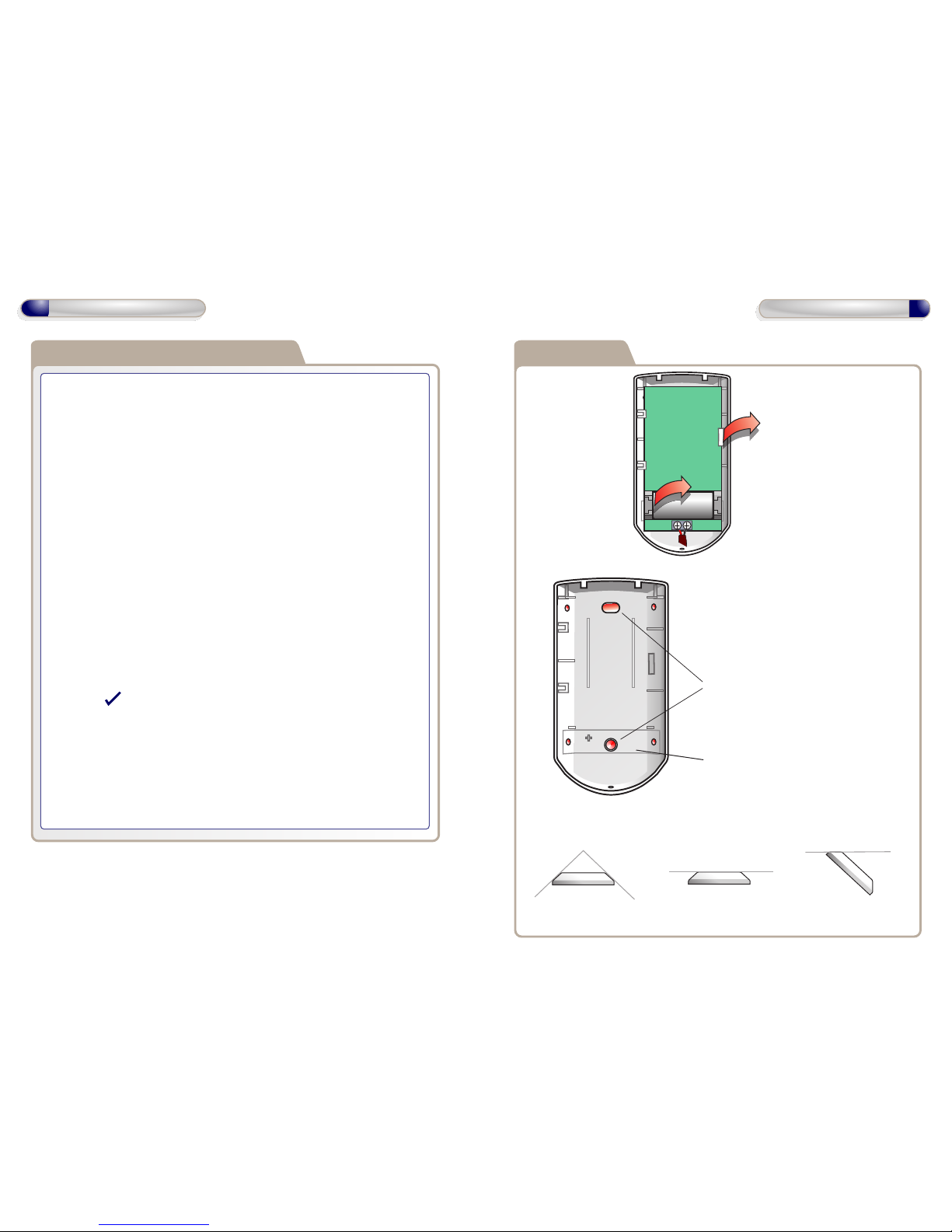
PA mounting
PA mounting
To remove PCB, push
clip forward
To remove Battery,
lift up
Fitted with
1 x ICR123
Rechargeable
750mA Battery
+ Power in 5V to 13V DC
Replace back tamper
plate if removed for
drilling holes through
Drill through appropriate pilot
holes in rear enclosure and mount
to wall
Mount Holes
mount with
2 x 1 inch No.8
security screws
2. Flat mounting
1. Corner mounting
3. Edge mounting
Base mounting diagrams.
Enrolling on a GSDi intrusion system
1.
2.
3.
4.
5.
6.
7.
8.
9.
On the system start enrolling: see GSDi installation manual for details.
Remove the front cover from GSDi-RF-RPT.
Remove battery Tab
Connect power (5 - 13V) to the Terminals, ie.:i70 Panel Aux Power
Press and hold the front tamper.
If removing PCB from the base, ensure that the back tamper is closed before
closing front tamper.
Wait about 5 seconds.
When the LED on the front lights, release the tamper switch.
- The sensor flashes the LED to indicate it is searching for the system.
- When it finds the system the Panel will display a message.
At the Panel click Finish or Test Device
- Test Device; Signal Range < Next > Status (Open /Tamper) < Next > Device
Name <
> Area < Next > Device Setting < Next > Finish
Replace front cover on GSDi-RF-RPT and secure it with the fixing screw.
Note: Any device using the Repeater will show Signal Boostings.
N.B. USE RECHARGABLE BATTERY ONLY.
RPT opening
2
Operation Instructions
3
Installation Diagrams
 Loading...