

GSD GSDn-WEC Installation & User Manual
Installation & User Manual V2.04
No.1 Turnpike Business Park,
Ballymount,
Dublin 22, Ireland.
Telephone: +353 1 524 2691.
Fax: +353 1 4430 430.
3
Contents
6
Installation Diagrams
9
8
System Overview
Wi-Enterprise Controller
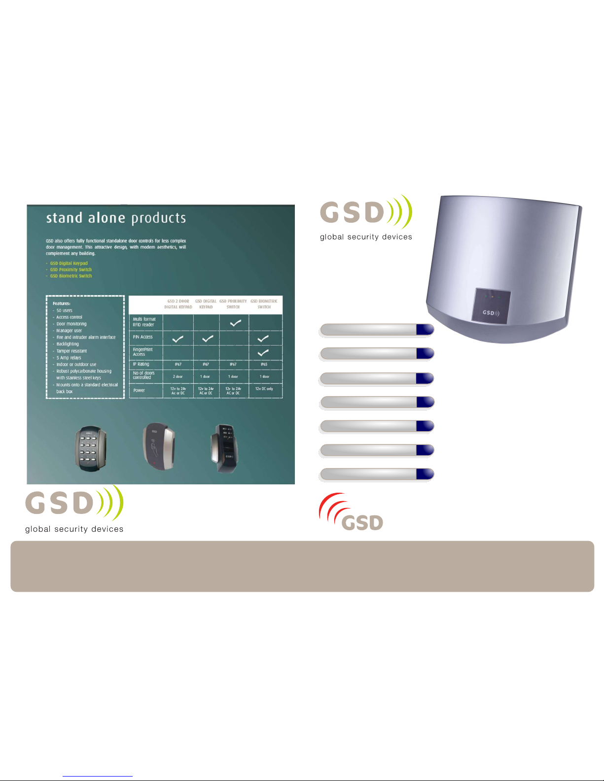
Other products from GSD
“Wireless Network
System”
GSD Wi-Max System is the next generation
in access control solutions. It provides a
Wireless Network throughout the premises,
giving the convenience and security of a fully
networked system for a fraction of the cost.
For more information on the Wireless Network System visit our website
www.globalsecurity.ie
4
Installation Instructions
12
Network Diagrams
Wiring Diagrams
19
Fingerprint Enrollment
Operation Instructions
2
3
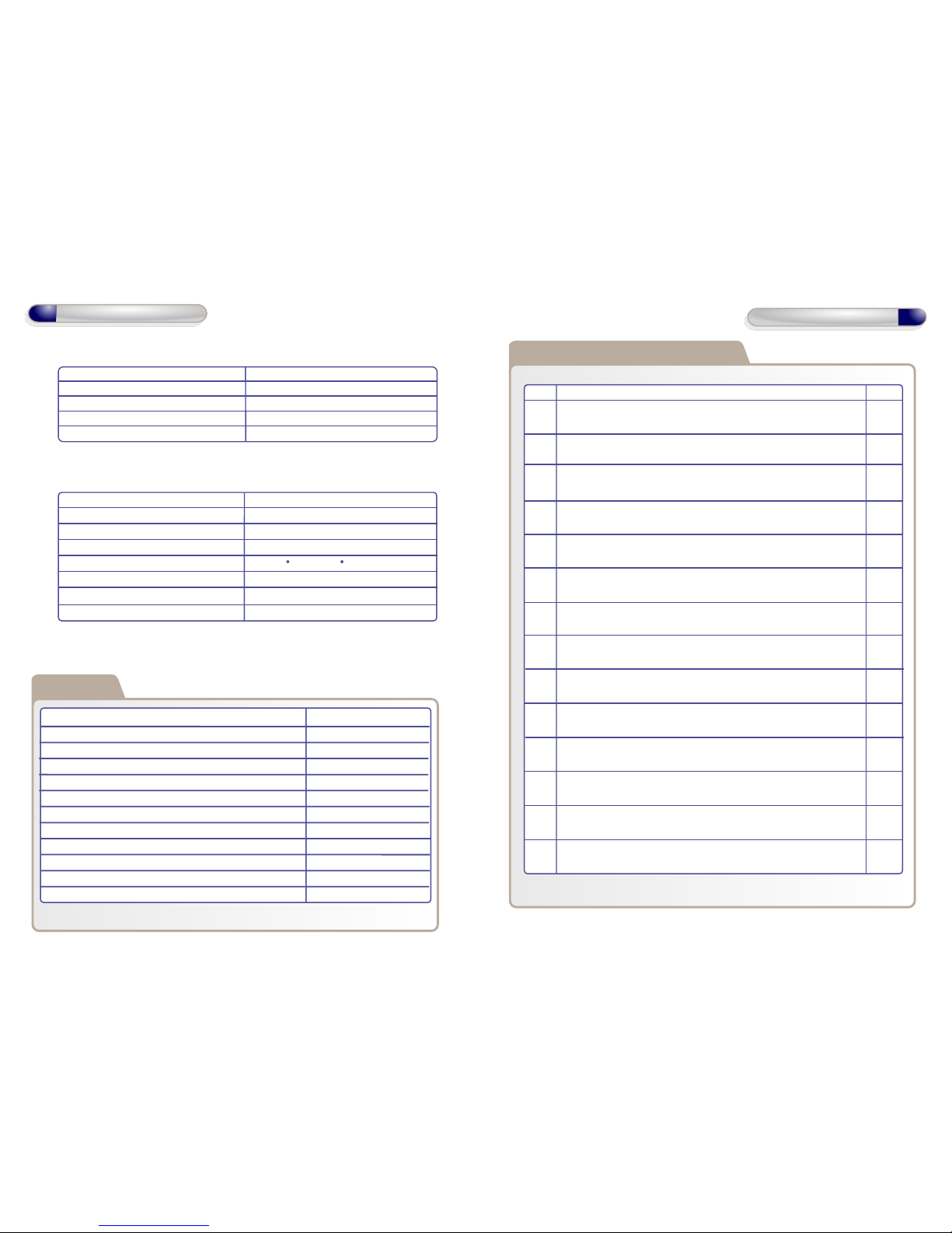
Technical Specification
Power Supply 230 VAC
Current consumption 30mA
Fuse Rating 230VAC 315mA T
Moisture Resistance Indoor Use Only
Dimensions W. 260mm D. 262mm H. 55mm
Technical Specs - GSD Wi-Enterprise Controller
Power Supply 12 DC
Current consumption 110mA
Current consumption with load (max) 145mA
Relay Contact Rating 5 Amps /230V ac
Operating Temperature - 20 C to +60 C
Moisture Resistance IP 67 ( IP65 on Wi-Bio )
Dimensions - Flush Mount W. 87mm D. 21mm H. 119mm
- Surface Mount W. 87mm D. 35mm H. 119mm
Technical Specs - Wi-
Enterprise
Door Controls
Features
Doors controlled
Users
User Groups
Time Zones
Door Groups
Reporting Facility
Challenge Facility
Logging
Input/Output Mapping
Supports Wireless & RS485 Networks
Automatic Backup Facility
Database Encryption
20
20000
128
128
128
Yes
Yes
Unlimited
CCTV & Lift control
Yes
Yes
Yes
Installation Steps
Step Description Page
1 Install the Controller using the Installation Diagrams 4-5
2 Wire the Controller using the Wiring Diagrams 8
3 Install and wire each Door Control. Refer to the Door Control
Manual for instructions.
4 Connect the Controller to the PC using Network Diagrams 9-11
5 Restoring Factory Defaults 11
6 Setting up TCP-IP 12
6 Phase 1- Setting up the GSD Controller 14
7 Phase 2 - Configuring the GSD Controller 15
8 Phase 3 - Enrolling Door Controls 16-18
9 Phase 4 - Configuring Users 19
10 Phase 5 - Configuring Access Levels 20
11 Phase 6 - Downloading Configuration 20
12 Enrolling User Fingerprints 21
13 Correct Finger Placement techniques 22-25
Installation Steps
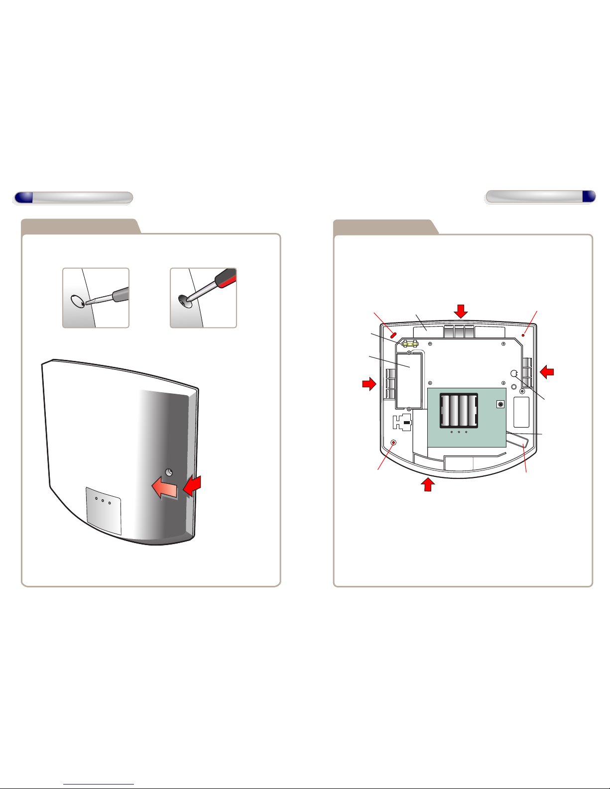
Control Panel opening
Control Panel features
remove screw cap
remove retaining
screw
to remove cover
pull forward on
right and slide left
mount with 4 x 1.5 inch
No. 8 Security Type screws
rear tamper
switch
cable
entry
cable
entry
cable
entry
cable
entry
spare cap
access to rear
void for wiring
spirit level
mains pcb
mount holemount hole
mount hole
4
Installation Diagrams
5
Installation Diagrams
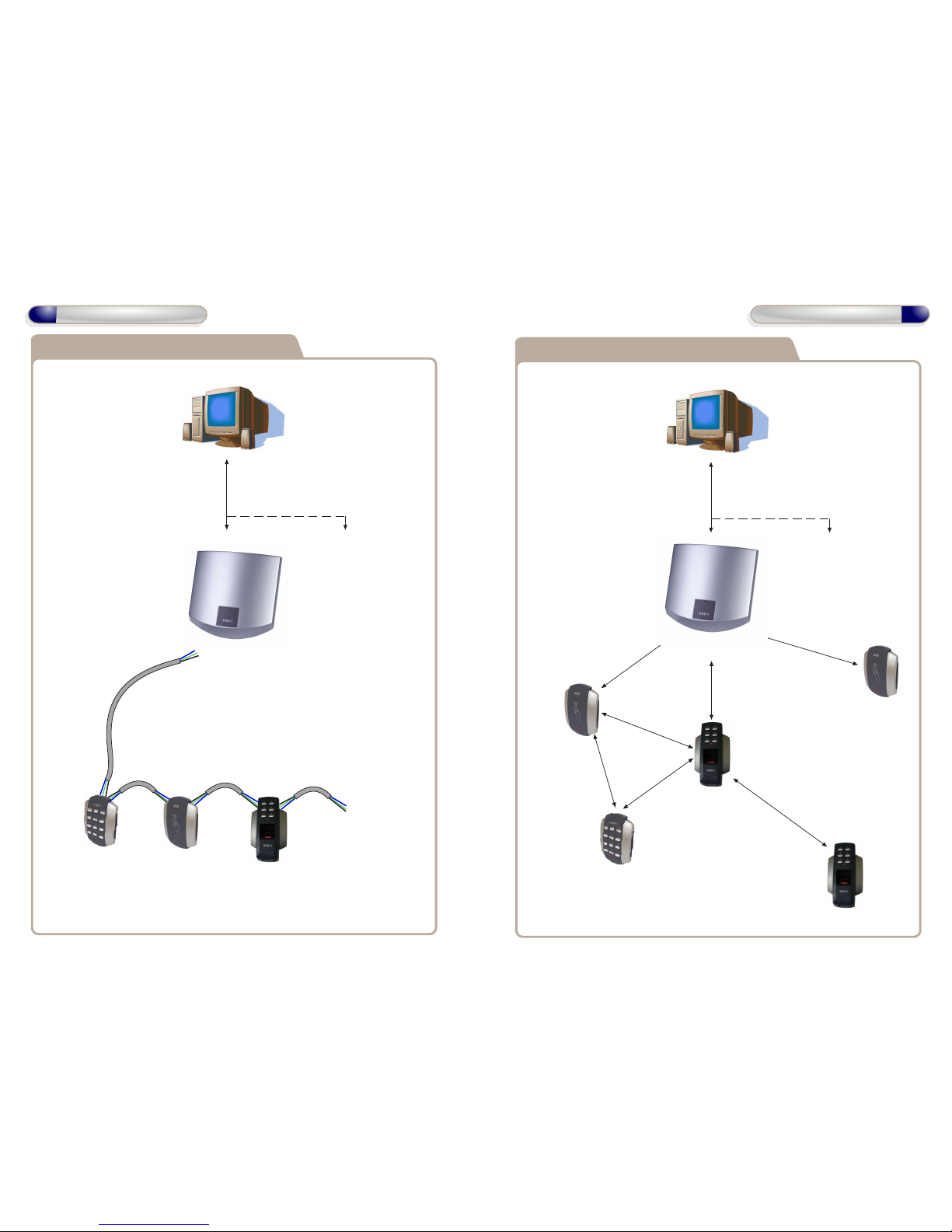
6
System Overview
Wireless Connection to Door Controls
Door Control
#1
Door Control
#2
Door Control
#3
Door Control
#5 - 20
TCP-IP connection to Controllers
or
RS485 Network to Controllers
Max number of Controllers 3
Max Cable Length 1.4 km
Controller
#1
Controller
#2 - 3
Door Control
#4
Note: Door Controls can be installed within 50 meters
of the Controller or within 50 meters of any other Door Control
as each Door Control will function as a repeater. Each repeater
transmits data to/from the Controller.
50 meters
7
System Overview
50 meters
50 meters
50 meters
50 meters
50 meters
50 meters
Note: If using a single Controller,
an RS232 cable may be used.
Max cable length 10 meters
RS485 Connection to Door Controls
Door Control
#1
Door Control
#2
Door Control
#3
Door Control
#4 - 20
RS485 Network to Door Controls
Max Cable Length 1.4 km.
Daisy Chain Configuration Only.
Controller
#1
Controller
#2 - 3
Note: If using a single Controller,
an RS232 cable may be used.
Max cable length 10 meters
Place a 120ohm
Termination Resistor
across A & B on the last
Door Control in the chain.
Place a 120ohm
Termination Resistor
across A & B on the
Controller
TCP-IP connection to Controllers
or
RS485 Network to Controllers
Max number of Controllers 3
Max Cable Length 1.4 km
Note : Used ONLY for
Wired 485 Network
Connections.
ABCOM
TX
RX
PC Network
PC Direct
PC Network Connections
can be used for multiple
controllers See page
10 for wiring
Wiring Diagrams
8
Wiring Diagrams
Door Network
A
B
COM
1 2 3 4
OFF
ON
TCP_IP
3V Lithium
Inputs/outputs
IP1
IP2
0V
IP3
IP4
12V
OP1
OP2
OP3
OP4
0V
VOUT
DAT
CLK
SEN
Inputs/outputs
Cable Tie
Fuse Rating : 230VAC 315mA
Warning : Installation should only be carried out
by a suitably qualified person only.
Cable Tie
retaining
clips
Main Input Cable
230VAC
Neutral
Earth
Live
Remove Battery Tab
Pull
9
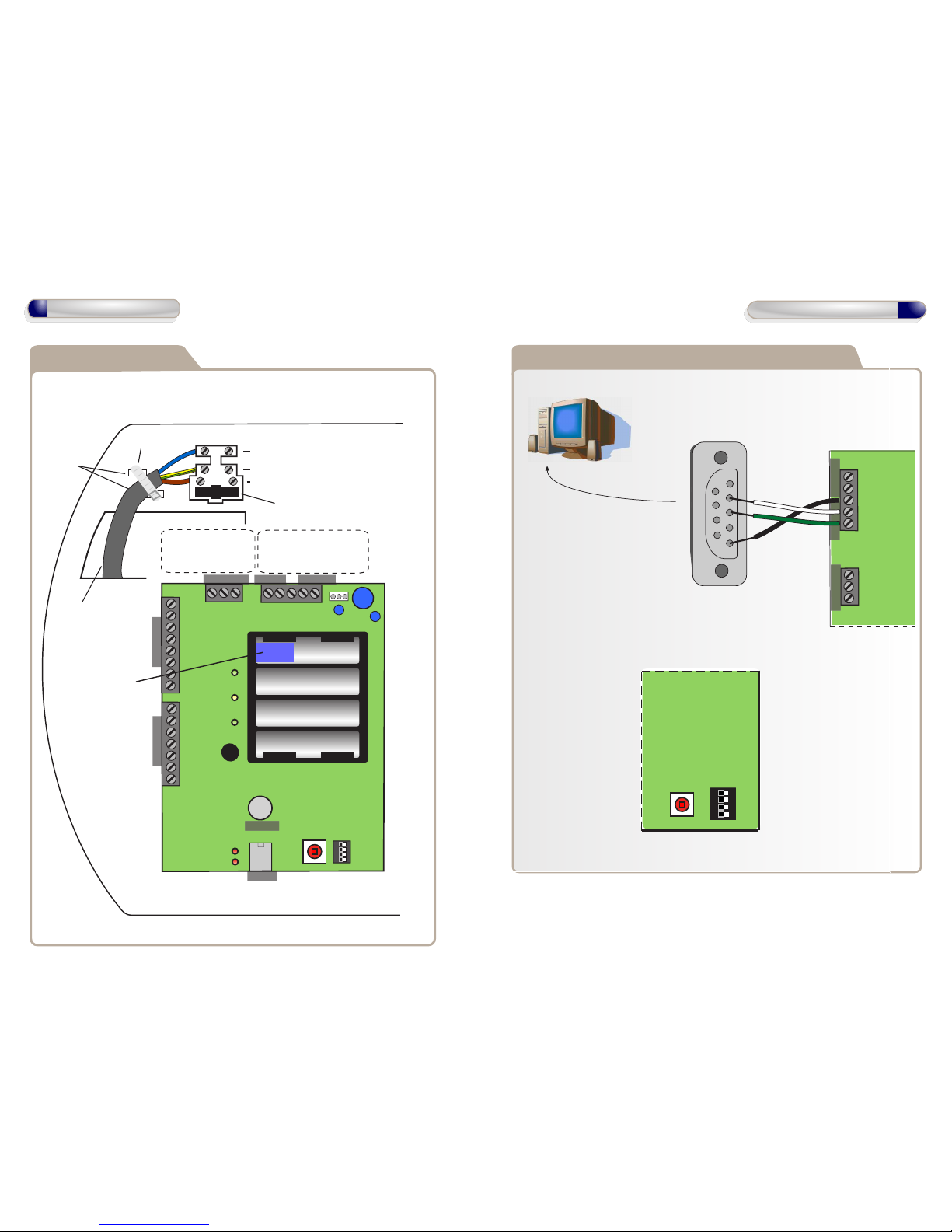
Network Diagrams for Single Controller
A
B
0V
TX
RX
A
B
0V
Door Network
PC Network
Connect DB9 cable
to serial port on PC
Maximum cable
length 10 meters
Direct Connect - All Dip Switches OFF
PC Direct
DB9 Female
Serial Cable
PC Direct Connection can be used, when
using ONLY one GSD Controller.
Set the Direct address to
ALL dip switches OFF
(see below )
Network Diagrams
OFF
ON
1 2 3 4
1
5
2
3
4
9
8
7
6
 Loading...