

Page 1

Installation & User Manual V1.1
No.1 Turnpike Business Park,
Ballymount,
Dublin 22, Ireland.
Telephone: +353 1 524 2691.
Fax: +353 1 4430 430.
2
Initial Setup
Contents
4
Installation Diagrams
6
Wiring Diagrams
12
Enrolling Door Controls
Wi-Smart
Other products from GSD
standalone products
GSD also offers fully functional standalone door controls for less complex door
management. This attractive design, with modern aesthestics, will complement
any building
- GSD Digital Keypad
- GSD Proximity Switch
- GSD Pin&Prox Switch
- GSD Biometric Switch
Features:
50 users
Access control
Door Monitoring
Manager User
Fire and Intruder alarm interface
Backlighting
Tamper resistant
5 amp relays
Indoor or outdoor use
Robust polycarbonate housing with stainless steel keys
Mounts onto a standard electrical back box
Page 2

15
2
Initial Setup
Power Supply 12V DC
Current consumption 70mA
Current consumption with load (max) 100mA
Relay Contact Rating 5 Amps /240V ac
Operating Temperature -20 C to +60 C
Moisture Resistance IP 67
Dimensions - Flush Mount W. 87mm D. 21mm H. 119mm
- Surface Mount W. 87mm D. 35mm H. 119mm
Number of Users 30000
Technical Specs
Initial Installation
The Door Control should be Factory Defaulted after installation. This will restore all
default settings to the Door Control and will unenrol it from any existing GSD
Controller.
The Door Control will then start to scan and enrol on a GSD controller.
Refer to the section ‘Enrolling Door Controls’ on page 12 for instructions on how to
configure the GSD Windows Software.
Installation Notes
Page 3

3
Initial Setup
Restoring Factory Settings:
Wi-Smart
Step Description
1 Present Programming Card 2 Times
2 Present Any Card Once
Programming
Card x 2
AnyCard
x 1
Adding a Programming Card
Note: Add a progrmming card to the Door Control. The Door Control must
be disabled first if it has been enrolled onto a GSD Network Controller.
Follow the method below to add a programming card to the Door Control.
Adding a Programming Card
AnyCard
x 2
Step Description
1 Remove security caps and power down unit.
Power up unit and Present Any Card 2 times
2 immediately. This card is now the Programming
Card for the unit. Refit security caps
Factory Default PIN codes
The following PIN codes are the Factory Default Settings:
- The Default Engineer code is ‘6666’
- User PIN ‘1111’
Note: The User PIN ’1111’ is deactivated when the Door Control is enrolled
onto a GSD Network Controller.
14
Wiring Diagrams
Wiring Diagram - Smart Slave
12V Linear
Power supply
Wi-Smart
(See manual for detailed
wiring diagram)
Data1/Clock OutputData0/Data Output
Tamper Alarm Output
12V DC
Only
0V
Buzzer Control Input
Green LED Input
Red LED Input
Card Present Output
Max Data Cable Length
- 100m Shielded Cable
Page 4

13
4
Installation Diagrams
When Surface Mounting the Door Control
a Surface Mount Collar is required.
- Fix Surface Mount Collar to
wall, ensure arrow is
pointing upwards
After fixing Surface Mount Collar to wall
(as above) and wiring is complete as per
wiring diagrams on pages 6-11, the Door
Control may then be screwed to
Surface Mount Collar using
security screws provided.
Both Security Caps are
then clipped onto the Door
Control.
To attach Security Caps: Simply
align the tabs into holes and push
on until click is heard.
Surface Mounting
Security Caps
Assigning a Door Address on Wireless Network
Step Description
1 On the Controller screen: Click ‘Wireless Network’ and then
Click ‘Allow Doors to Join this Controller’
All Door Controls that don’t have an address start to beep out the next
available address. The Keys will also illuminate to indicate the next
address. e.g Keys 1 & 5 will be ON for address number 15.
2 Hit any key on the ‘beeping’ Door Control to assign this address or
present a Card on the ‘beeping’ Proximity unit to assign this address.
When a Door Control is assigned an address, all unassigned Door
Controls will start to beep the next available address.
3 When all doors are assigned: Click ‘Secure Network’
Note: While assigning door addresses, leave the Controller Screen open or the
network will be Secured automatically , stopping doors from joining the network.
Assigning a Door Address on a Wired 485 Network
Step Description
1 Right Click on the Controller Icon & select ‘Manually Assign Addresses’
Follow Step 2 above to complete the process.
Enrolling Door Controls
Page 5

5
Installation Diagrams
To release Security Caps push a
screwdriver into slots on the side
and pull forward.
Door Control is mounted to electrical pattress box using security
screws provided. Both Security Caps are
then clipped onto Door Control.
Flush Mounting
To attach Security Caps: Simply
align the tabs into holes and push
on until click is heard.
Adding Door Controls
12
Enrolling Door Controls
Step Description
1 Click the Doors Icon on the left hand toolbar (see 1 above)
2 Click ‘Add New Door’ (see 2 above)
3 The Door is added to the Controller.
4 Configure the required Door settings : Door Timers, Alarm Options,
Door Options, Timed Actions, Inputs & Outputs.
5 Click ‘Save’ to transmit the changes to the GSD Controller.
(see 5 above)
1
2
5
Page 6
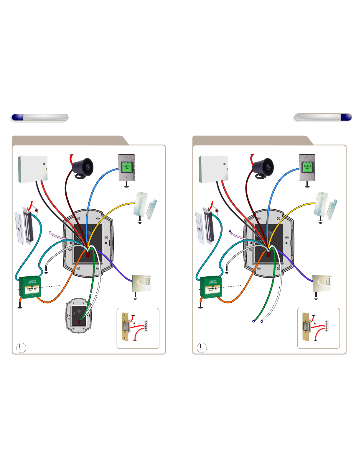
12V
Wiring Diagram with Slave Reader
12V Linear
Power supply
Door Exit Button
0V
Door
Contact
0V
Common the OV from the
Fire Alarm Panel and the OV
from the Door Control to
avoid any ground loop issues.
Fire Alarm
Panel
0V
When the fire alarm
is activated (0V removed
from IP4) the door will
be opened
12V
Sounder
6
Wiring Diagrams
Smart Slave
(See page 14 for detailed
wiring diagram)
12V
0V
NO
COM
NC
12 - 24 VAC
12 - 24 VAC
Wiring for StikeLock only using 12 - 24VAC supply
Note: All OV shown in the
diagram are connected to
OV of the Door Control.
0V
Dual-Pole
Ressetable
BreakGlass Unit
0V
Pole to cut
power to Lock
Pole for
Monitoring
Unit
NC
0V
COM
NO
IP5
Break Glass
OP1
Data1/Clock
IP3
Data0/Data
IP4
Fire Alarm
IP2
Door
Contact
IP1
Door Exit
Button
OP2
Alarm/Sounder
12V DC
Only
0V
Suggested Wiring
for BreakGlass
Unit above.
12V
Wiring Diagram with External IP3 Function
12V Linear
Power supply
Door Exit Button
0V
Door
Contact
0V
Fire Alarm
Panel
0V
12V
Sounder
12V
0V
NO
COM
NC
12 - 24 VAC
12 - 24 VAC
Wiring for StikeLock only using 12 - 24VAC supply
Note: All OV shown in the
diagram are connected to
OV of the Door Control.
0V
Dual-Pole
Ressetable
BreakGlass Unit
0V
Pole to cut
power to Lock
Pole for
Monitoring
Unit
NC
0V
COM
NO
IP5
Break Glass
OP1
IP3
IP4
Fire Alarm
IP2
Door
Contact
IP1
Door Exit
Button
OP2
Alarm/Sounder
12V DC
Only
0V
Suggested Wiring
for BreakGlass
Unit above.
- Card and Pin
- Card or Pin
- Lock Door
(selectable from
“Doors” tab in PC
Application)
Follow
Relay
11
Wiring Diagrams
Max Data Cable Length
- 100m Shielded Cable
Note: Fire Alarm Override is
deactivated until the Door
Control joins a network.
Common the OV from the
Fire Alarm Panel and the OV
from the Door Control to
avoid any ground loop issues.
When the fire alarm
is activated (0V removed
from IP4) the door will
be opened
Note: Fire Alarm Override is
deactivated until the Door
Control joins a network.
16V
Varistor
16V
Varistor
16V
Varistor
16V
Varistor
Page 7
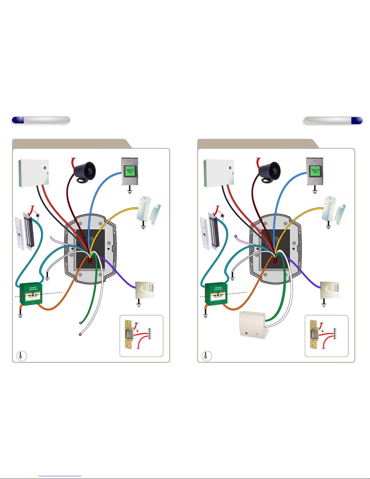
Arm Alarm Input
Arm Output (N/O)
12V
Wiring Diagram with Interlock Connection
12V Linear
Power supply
Door Exit Button
0V
Door
Contact
0V
Fire Alarm
Panel
0V
12V
Sounder
10
Wiring Diagrams
12V
0V
NO
COM
NC
12 - 24 VAC
12 - 24 VAC
Wiring for StikeLock only using 12 - 24VAC supply
Note: All OV shown in the
diagram are connected to
OV of the Door Control.
0V
Dual-Pole
Ressetable
BreakGlass Unit
0V
Pole to cut
power to Lock
Pole for
Monitoring
Unit
NC
0V
COM
NO
IP5
Break Glass
OP1
IP3
IP4
Fire Alarm
IP2
Door
Contact
IP1
Door Exit
Button
OP2
Alarm/Sounder
12V DC
Only
0V
Suggested Wiring
for BreakGlass
Unit above.
12V
Wiring Diagram with Intruder Alarm Panel
12V Linear
Power supply
Door Exit Button
0V
Door
Contact
0V
Fire Alarm
Panel
0V
12V
Sounder
12V
0V
NO
COM
NC
12 - 24 VAC
12 - 24 VAC
Wiring for StikeLock only using 12 - 24VAC supply
Note: All OV shown in the
diagram are connected to
OV of the Door Control.
0V
Dual-Pole
Ressetable
BreakGlass Unit
0V
Pole to cut
power to Lock
Pole for
Monitoring
Unit
NC
0V
COM
NO
IP5
Break Glass
IP4
Fire Alarm
IP2
Door
Contact
IP1
Door Exit
Button
OP2
Alarm/Sounder
12V DC
Only
0V
Suggested Wiring
for BreakGlass
Unit above.
IP3 OP1
Interlock OP (OP1) to
Interlock IP on
2nd Door
Interlock IP (IP3) from
Interlock OP on
2nd Door
7
Wiring Diagrams
Intruder Alarm
Panel
Common the OV from the
Fire Alarm Panel and the OV
from the Door Control to
avoid any ground loop issues.
When the fire alarm
is activated (0V removed
from IP4) the door will
be opened
Note: Fire Alarm Override is
deactivated until the Door
Control joins a network.
Common the OV from the
Fire Alarm Panel and the OV
from the Door Control to
avoid any ground loop issues.
When the fire alarm
is activated (0V removed
from IP4) the door will
be opened
Note: Fire Alarm Override is
deactivated until the Door
Control joins a network.
16V
Varistor
16V
Varistor
16V
Varistor
16V
Varistor
Page 8
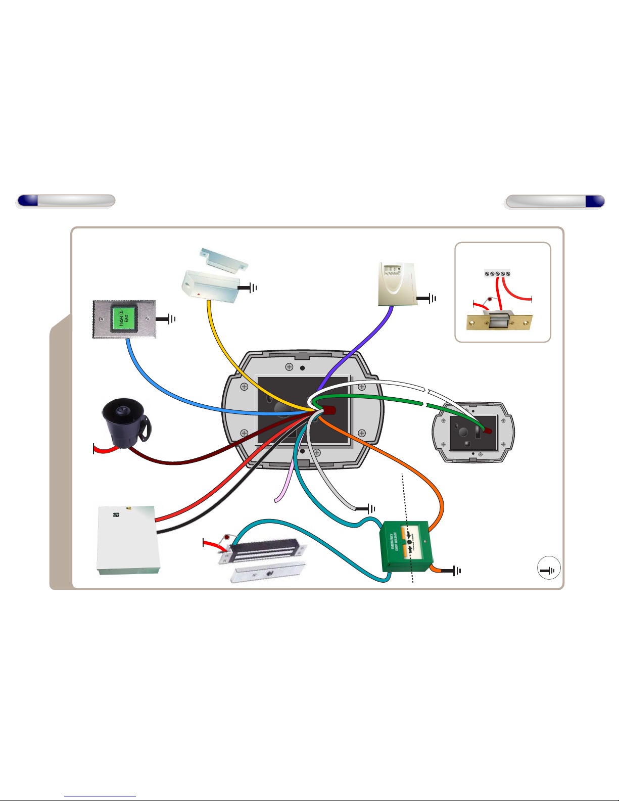
12V
Wiring Diagram with Slave Reader
12V Linear
Power supply
Door Exit Button
0V
Door
Contact
0V
Common the OV from the
Fire Alarm Panel and the OV
from the Door Control to
avoid any ground loop issues.
Note: Fire Alarm Override is
deactivated until the Door
Control joins a network.
Fire Alarm
Panel
0V
When the fire alarm
is activated (0V removed
from IP4) the door will
be opened
12V
Sounder
Smart Slave
(See page 14 for
wiring diagram)
12V0VNO
COM
NC
12 - 24 VAC
12 - 24 VAC
Wiring for StikeLock only using 12 - 24VAC supply
Note: All OV shown in the
diagram are connected to
OV of the Door Control.
0V
Dual-Pole
Ressetable
BreakGlass Unit
0V
Pole to cut
power to Lock
Pole for
Monitoring
Unit
NC
0V
COM
NO
IP5
Break Glass
OP1
Data1/Clock
IP3
Data0/Data
IP4
Fire Alarm
IP2
Door
Contact
IP1
Door Exit
Button
OP2
Alarm/Sounder
12V DC
Only
0V
Suggested Wiring
for BreakGlass
Unit above.
8
Wiring Diagrams
9
Wiring Diagrams
Max Data Cable Length
- 100m Shielded Cable
16V
Varistor
16V
Varistor
 Loading...