

GSC MSR-441 Handbook
MSR-441 Credit Card
Access Control System
User Handbook
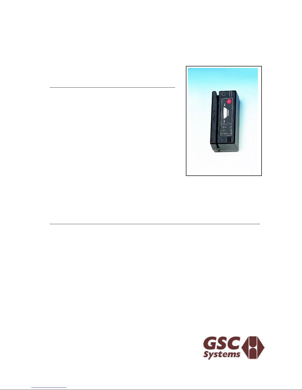
GENERAL DESCRIPTION
The MSR-441 is a low cost stand-alone
programmable access control system incorporating a magnetic card reader. This reader
will read magnetic cards programmed on
track 2 as specified by ISO 3554, such as
credit cards and EC cards.
The card read head, electronics, memory
and relay circuitry are contained in a robust
housing for simple installation. The
minimum connection just requires 12V AC or
DC and a door strike.
When the reader is powered up, all credit
cards that are swiped will be accepted for 24
hours a day. A Function Card supplied with
the reader allows the setting up of the strike
relay time. The function card is unique to each system thus preventing another
customer with the same product from tampering on different sites.
THE SYSTEM FUNCTION CARD
The FUNCTION CARD is required to set up a "site" consisting of one or several
MSR-441 readers. The Function Card is marked and used as follows:
TIME ADJUST CARD
Swiping this card causes the Yellow POWER lamp to start flashing. Each flash adds
0.25s to the relay operating time. When the required number of flashes have passed,
swipe the Time Adjust card again to terminate the function.
The new relay operating time will be stored permanently in memory. The time can be
changed at any time and may be set from 0.25s to 12s.
In addition an optional door monitoring switch may be connected to the system to reset
the relay circuit when the door is opened, irrespective of the strike time setting.
MSR441 User Handbook rev2.lwp Page 1 of 3

INSTALLATION
POWER
Connect 7-10V AC or 10-14V DC to the two terminals marked ~. The polarity of the
connection is not important.
DOOR STRIKE
The unit provides a relay output rated at 24 VDC at 1A . The following contacts, that
are isolated from the rest of the board, are provided; normally open (NO) contact,
normally closed (NC) contact and a common (COM).
Typical connections to a door strike are shown on page 3.
Note: A time switch may be connected as shown to "Inhibit" or to disable the reader
during certain times.
Note: When using a strike with DC the relay contacts will be damaged by arcing due to
back EMF when the contact opens. Use a IN4001 diode as shown on the drawing to
prevent this damage.
DOOR MONITORING SWITCH
If a door monitor switch is used, the door strike will be reset the moment the door is
opened. This ensures that the door will always lock even if a long strike time is set.
The switch must close when the door opens and is wired between DOOR and GND on
the reader base.
Push-button
A push-button may be connected to allow remote operation of the door strike relay.
The push button must be normally open and is wired between the PUSH-BUTTON
and GND connections on the reader base.
OPERATION
On first time power up of the unit the following sequence will occur:
x all 3 lamps will go on for 1.5 seconds.
x the three lamps will flicker asynchronously showing that the reader
memory is being initialised.
x the POWER lamp will stay on permanently.
Whenever a card is now swiped successfully through the reader the PASS lamp will
go on, the door strike relay will operate. If the printer option is used, a line of text will
be printed giving the first 16 digits of the card number.
The door strike and PASS lamp will stay on for the programmed door strike time
(0.25s - 12s). If a door switch is connected to the unit the door strike relay and PASS
lamp will go off as soon as the door is opened.
If a card is not recognised or is of the wrong format the FAIL lamp will go on for 1.5
seconds after swiping the card.
MSR441 User Handbook rev2.lwp Page 2 of 3
 Loading...