

GSC 180 Series Handbook

180 Series
Keypad
Handbook
Revision 2.1

Revision History
Revision 1.0 Initial release
Revision 2.0 Major update with addition of 180-40
Added 180-40 to document and various headings
Note regarding unique address for RS-485 - page 14
Changed section on installation - page 16
Added section on RS-485 - page 19
Added Reject Codes - page 23
Revision 2.1 Corrected drawing on page 20 - jumpers must be ON

Table Of Contents
24
PIN Record Sheet
23
Rejection Reason Codes
23
Master PIN Reset Procedure
22
Software (180-20 & 180-40 Only)
22Unit IDs & RS-485
22Termination Jumper
22RS 232/485 Selection
20
RS-485 Connection (180-40 Only)
19
RS-232 Connection (180-20 & 180-40 Only)
19Clear Transaction Log - 63# (180-20 & 180-40 Only)
19Clear PIN Memory - 62#
19Reset Factory Defaults - 61#
18Clear/Reset Function
18Beeper
17Examples
17Connections
17
Installation (All Models)
16
Duress Function
16Set Date - 52# (180-20 & 180-40 Only)
15Set Time - 51# (180-20 & 180-40 Only)
15
Date and Time
15Set ID - 460# (180-20 & 180-40 Only)
15PIN Entry Mode - 451#
14Lockout Indication - 444#
14Lockout Output Code - 443#
14Lockout Timeout - 442#
14Lockout Failed Attempt - 441#
13Lockout Mode
13Input-2 Function - 433#
13Input-1 Function - 432#
13ComboKey Function - 431#
12Inputs - Overview
12Output 2 Function - 423#
12Output 1 Function - 422#
11Relay Function - 421#
11Outputs - Overview
11Minimum Open Time - 414#
10PIN Length - 413#
10PIN Capacity - 411#
10Master PIN - 401#
10
Commands - Configuration
9
Commands - Delete PIN
7
Command - Set Expiry (180-20 & 180-40 Only)
7Address PIN Mode (mode explanation on page 2)
5Normal PIN Mode (default) (mode explanation on page 2)
5Simple Add PIN
5
Commands - Add PIN
4Exit Command Mode
4Enter Command Mode
4
Entering and Exiting Command Mode (Programming)
4
Default factory settings:
3Operation
3Address PIN Mode - Address Mode On
3Normal PIN Mode - Address Mode Off (default)
3
Normal Mode (Access Control)
3
Power-up
3
Overview

180 Series Keypad
Overview
The 180-10, 180-20 & 180-40 keypads provide simple yet flexible access control of a
single door.
The “out of the box” default settings make installation and operation simple. For more
complex requirements, the unit has a set of programming functions that make the
keypad highly configurable.
The 180-20 keypad is more advanced and has a real time clock, memory to log
transactions and a RS-232 serial port for connection to a computer.
The 180-40 has the same features as the 180-20 but allows up to 64 units to be
connected to a computer via RS-485.
Programming and logging of activities can be done with the 180 - Keypad software
(Windows based).
Power-up
On power-up the Green LED will flash fast for a few seconds while the keypad is
initialised. On completion the Yellow will give a short flash every 1 to 2 seconds
indicating the unit is in Normal Mode and ready for a user to enter their PIN code.
Normal Mode (Access Control)
Every user has a PIN which is stored at a memory address.
The unit operates in either Normal PIN or Address PIN mode depending on the
setting of the ‘PIN Address Mode’ in the configuration ( see page 14 for details) and
this determines how a user enters their PIN to gain access.
Normal PIN Mode - Address Mode Off (default)
In this mode the user enters the PIN code (default 4 digits) and the keypad searches
for the first occurrence of that PIN number and applies the access parameters
associated with that PIN. The settings of the same PIN code stored at a higher
address will never be used.
Address PIN Mode - Address Mode On
In this mode the user must enter their address and their PIN code. The keypad goes
directly to the address and uses the access parameters at that address.
The entry format is: ADDRESS # PIN
If the address is 009 and the PIN is 7834 the entry would be: 9#7834
Although more keystrokes are required, this mode has the advantage that users can
program their own PIN codes.
Operation
If a valid PIN is entered and access allowed, the Green LED will light and the outputs
will operated as determined by the parameters for that PIN.
If access is denied, the Red LED will light. (See page 22 for more information).
180-Series Keypad Handbook rev 2.1 page 2 of 23

Default factory settings:
The default settings have been chosen to meet most small installation requirements.
The only setting that must be changed is the Master PIN
460#1ID (180-20 Only)
451#OffPIN Address Mode
444#OffLockout indication
443#Output-1Lockout code
442#30 secLockout Time
441#3 AttemptsLockout
433#Door SenseInput 2
432#Exit PushbuttonInput 1
431#Output-1 (3 sec)ComboKey
423#CCTV (10 sec)Output 2
422#Alarm (3 sec)Output 1
421#Switch (5 sec)Relay
414#0.5 secRelay holdoff Time:
413#4PIN Length:
411#100PIN Capacity:
401#12345678Master PIN:
Program CodeDefault ValueFeature
The PIN length must be decided before adding PINs - changing the PIN
Length will corrupt the PIN codes.
Entering and Exiting Command Mode (Programming)
All command functions (programming) require that the keypad is in
Command Mode.
Enter Command Mode
Command Mode - waiting for command codeYellow Steady
Hold down the
* key and at the same time enter
the Master PIN code and then release the * key.
Yellow Flashing
Normal ModeYellow Flashing
Exit Command Mode
Normal ModeYellow Flashing
Writing to memoryGreen Fast Flash
Press
*
Yellow Steady
180-Series Keypad Handbook rev 2.1 page 3 of 23

Commands - Add PIN
The add PIN command is the most complex of all the commands because of the
number of options that are available. Do not attempt complex programming of PINs
without carefully studying this section and the section on Outputs.
The “Simple Add PIN” method described below can be used for most applications.
Simple Add PIN
This method assumes that the unit is used with the factory default settings, all PINs
will have the same settings and a valid PIN will operate the relay.
Each entry will require an address and an associated PIN code. All entries should be
recorded and an example recording sheet is included at the back of this document.
The address must be in the range 1 - 800.
Normal ModeYellow Flashing
Press * to terminate Program ModeYellow Steady
Program mode waiting for a commandYellow Steady
Press # - terminates Add PIN commandYellow Steady + Green Flash
Repeat as many times as required
Enter PIN # - e.g. 9235#
Yellow Steady + Double Green Flash
Enter next PIN address # - e.g. 24#
Yellow Steady + Green Flash
Enter PIN # - e.g. 2835#
Yellow Steady + Double Green Flash
Enter address # - e.g. 23#
Yellow Steady + Green Flash
11 # (Add PIN command)Yellow Steady
Program mode waiting for a commandYellow Steady
Enter MASTER code (see page 3)Yellow Flashing
Explanation / ActionLED Status
Once all the PINs are programmed, the unit is ready for operation in “Normal PIN
Mode - Address Mode Off” as explained on page 142
Normal PIN Mode (default) (mode explanation on page 2)
In the Normal PIN Mode of operation all the PINs have to be added by the system
operator. PINs are not secret as they are recorded by the operator. All entries should
be recorded and an example recording sheet is included at the back of this document.
The Add PIN command is a two stage command:
1st Stage: 1 code (inhibit) #
where the parameter code is replaced by a value from the table below and
parameter (inhibit) is optional (see explanation below).
The unit is now in Add PIN mode
2nd Stage: address # PIN #
where the parameter address is the memory address where the PIN is stored
and PIN is the code stored at that address.
The address must be in the range 1 - 800
180-Series Keypad Handbook rev 2.1 page 4 of 23
Explanation of parameters
The command has a code value which determines which of the Relay, Output-1 and
Output-2 are operated when a valid PIN is entered.
Relay & Output-1& Output27
Output-1 & Output-26
Relay & Output-25
Output-24
Relay & Output-13
Output-12
Relay1
Valid PIN functioncode
The command also allows for an optional inhibit function which is associated with an
input configured as an inhibit input. This input can be connected to an external switch.
When the switch is closed access will be denied to any PIN whose with an inhibit
parameter is set to 1.
By default the inhibit value is always 0 (off) and does not need to be programmed if
inhibit is not required.
Once in the Add PIN mode, all PINs added will have the same code and inhibit
parameter. To add PINs with different parameters, terminate the Add mode and then
start the Add PIN command with the new parameters.
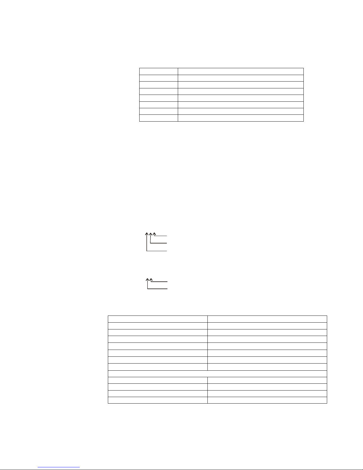
Examples of the Add PIN command:
PIN records configured to operate the Relay and Output-1, and access is subject
to the state of the Inhibit Input.
131#
Inhibit On
Output Code
Add PIN Command
PIN records configured to operate only the Relay and no Inhibit.
11#
Output Code
Add PIN Command
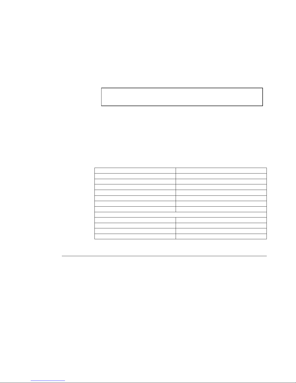
The programming status is indicated by the Green and Yellow LEDs and is explained
in the table below:
Normal ModeYellow Flashing
Press * to terminate Program ModeYellow Steady
Program mode waiting for a commandYellow Steady
Press # - terminates Add PIN commandYellow Steady + Green Flash
Repeat as many times as required
Enter PIN # - e.g. 9235#
Yellow Steady + Double Green Flash
Enter next PIN address # - e.g. 24#
Yellow Steady + Green Flash
Enter PIN # - e.g. 2835#
Yellow Steady + Double Green Flash
Enter address # - e.g. 23#
Yellow Steady + Green Flash
1 code (inhibit) # - e.g. 11#
Yellow Steady
Program mode waiting for a commandYellow Steady
Enter MASTER codeYellow Flashing
Explanation / ActionLED Status
180-Series Keypad Handbook rev 2.1 page 5 of 23
Address PIN Mode (mode explanation on page 2)
Before using this mode the configuration
In this Mode PINs can be added as previously described on page 4.
A more secure method is to allow each person to enter their own PIN thus ensuring
that the PINs are secret.
To use this method, PIN addresses are allocated with a blank PIN and each user
automatically adds their PIN the first time they use the unit to gain access.
The configuration setting - ‘PIN Entry Mode’ must be set to 1 to use this
method - see page 14 for details.
As before, the Add PIN command is a two stage command:
1st Stage: 1 code (inhibit) # (see above for explanation of parameters).
The unit is now in Add PIN mode.
2nd Stage address # # (address in the range 1 -800)
Adds a blank PIN to the selected address - this can be repeated for all addresses that
have the same code and (inhibit) parameters.
The programming status is indicated by the Green and Yellow LEDs and is explained
in the table below:
Normal ModeYellow Flashing
Press * to terminate Program ModeYellow Steady
Program mode waiting for a commandYellow Steady
Press # - terminates Add PIN commandYellow Steady + Green Flash
Repeat as many times as required
Enter # - blank PIN is enteredYellow Steady + Double Green Flash
Enter next PIN address # - e.g. 24#
Yellow Steady + Green Flash
Enter # - blank PIN is entered Yellow Steady + Double Green Flash
Enter address # - e.g. 23#
Yellow Steady + Green Flash
1 code (inhibit) # - e.g. 11#
Yellow Steady
Program mode waiting for a commandYellow Steady
Enter MASTER codeYellow Flashing
Explanation / ActionLED Status
Command - Set Expiry (180-20 & 180-40 Only)
Each PIN record can be set for limited access either by limiting the number of
accesses allowed or by an expiry date. Access is suspended when the count limit is
reached or the date is passed. The PIN record is not deleted and can be reinstated by
setting a new count value or expiry date.
The Expiry command structure is:
2 # Address # Mode # Value #
where the parameters are: Address - address of the PIN to set
Mode - set count or date expiry mode
Value - expiry count value or date
180-Series Keypad Handbook rev 2.1 page 6 of 23
 Loading...