

Page 1
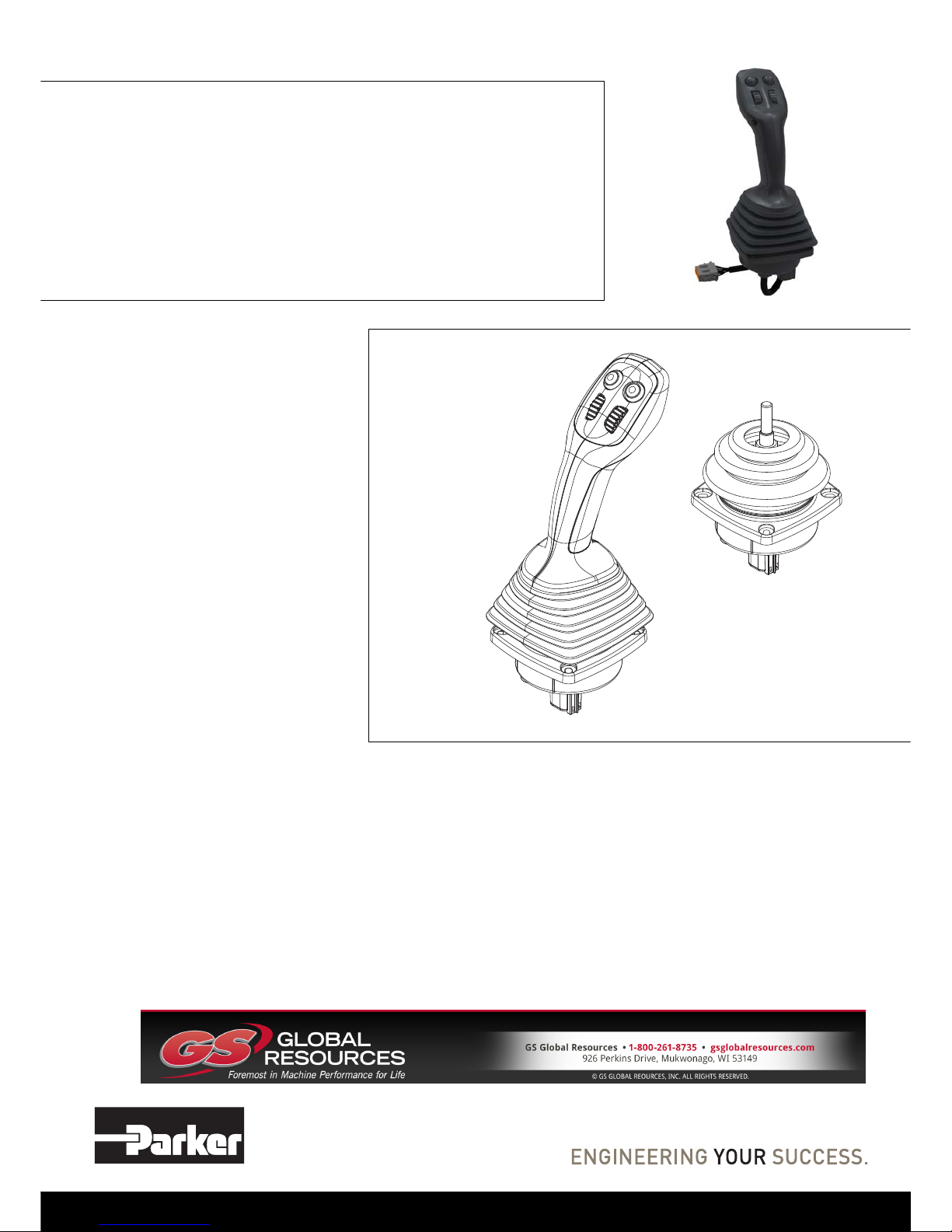
IQAN-LC5-X05
Instruction book
Publ no HY33-8402-IB/UK
Edition 2016-08-09
Page 2

ii
Contents
Instruction book, IQAN-LC5-X05
Contents
1 Introduction . . . . . . . . . . . . . . . . . . . . . . . . . . . . . . . . . . . . . . . . . . . . . . . . . . . . 1
Safety symbols . . . . . . . . . . . . . . . . . . . . . . . . . . . . . . . . . . . . . . . . . . . . . . . . 1
2 Precautions . . . . . . . . . . . . . . . . . . . . . . . . . . . . . . . . . . . . . . . . . . . . . . . . . . . . 2
General safety regulations . . . . . . . . . . . . . . . . . . . . . . . . . . . . . . . . . . . . . . . 2
Construction regulations . . . . . . . . . . . . . . . . . . . . . . . . . . . . . . . . . . . . . 2
Safety during installation . . . . . . . . . . . . . . . . . . . . . . . . . . . . . . . . . . . . . 2
Safety during start-up . . . . . . . . . . . . . . . . . . . . . . . . . . . . . . . . . . . . . . . 3
Safety during maintenance and fault diagnosis . . . . . . . . . . . . . . . . . . . 3
3 Product description . . . . . . . . . . . . . . . . . . . . . . . . . . . . . . . . . . . . . . . . . . . . . 4
IQAN-LC5-X05 . . . . . . . . . . . . . . . . . . . . . . . . . . . . . . . . . . . . . . . . . . . . . . . . 4
The control lever's parts . . . . . . . . . . . . . . . . . . . . . . . . . . . . . . . . . . . . . 4
The IQAN-LC5-X05 control signals . . . . . . . . . . . . . . . . . . . . . . . . . . . . . 5
I/O overview, base . . . . . . . . . . . . . . . . . . . . . . . . . . . . . . . . . . . . . . . . . . . . .5
MP handle . . . . . . . . . . . . . . . . . . . . . . . . . . . . . . . . . . . . . . . . . . . . . . . . . . . 6
The handle's parts . . . . . . . . . . . . . . . . . . . . . . . . . . . . . . . . . . . . . . . . . . 6
I/O overview, MP handle . . . . . . . . . . . . . . . . . . . . . . . . . . . . . . . . . . . . . . . . 7
Outputs . . . . . . . . . . . . . . . . . . . . . . . . . . . . . . . . . . . . . . . . . . . . . . . . . . 7
4 Safety . . . . . . . . . . . . . . . . . . . . . . . . . . . . . . . . . . . . . . . . . . . . . . . . . . . . . . . . . 8
IQAN-LC5-X05 . . . . . . . . . . . . . . . . . . . . . . . . . . . . . . . . . . . . . . . . . . . . . . . . 8
Redundant signals . . . . . . . . . . . . . . . . . . . . . . . . . . . . . . . . . . . . . . . . . 8
Use of limited signal range . . . . . . . . . . . . . . . . . . . . . . . . . . . . . . . . . . . 8
5 Mounting . . . . . . . . . . . . . . . . . . . . . . . . . . . . . . . . . . . . . . . . . . . . . . . . . . . . . . 9
Mounting the unit . . . . . . . . . . . . . . . . . . . . . . . . . . . . . . . . . . . . . . . . . . . . . . 9
Mounting considerations . . . . . . . . . . . . . . . . . . . . . . . . . . . . . . . . . . . . . 9
Mounting methods . . . . . . . . . . . . . . . . . . . . . . . . . . . . . . . . . . . . . . . . . . 9
Handle considerations . . . . . . . . . . . . . . . . . . . . . . . . . . . . . . . . . . . . . . . . . 10
Recommended handle specification . . . . . . . . . . . . . . . . . . . . . . . . . . . 10
Environmental specification . . . . . . . . . . . . . . . . . . . . . . . . . . . . . . . . . 10
Handle configuration to fit -U2 bellow . . . . . . . . . . . . . . . . . . . . . . . . . . 11
6 Installation . . . . . . . . . . . . . . . . . . . . . . . . . . . . . . . . . . . . . . . . . . . . . . . . . . . . 12
IQAN-LC5-X05 connector C1 . . . . . . . . . . . . . . . . . . . . . . . . . . . . . . . . . . . . 12
Connector C1 pin assignments . . . . . . . . . . . . . . . . . . . . . . . . . . . . . . . 12
G handle connector, 6 position . . . . . . . . . . . . . . . . . . . . . . . . . . . . . . . . . . . 13
Connector, 6 position assignments . . . . . . . . . . . . . . . . . . . . . . . . . . . . 13
G handle function for 6 position connector. . . . . . . . . . . . . . . . . . . . . . 13
MP handle connector, 6 position . . . . . . . . . . . . . . . . . . . . . . . . . . . . . . . . . 14
Connector, 6 position assignments . . . . . . . . . . . . . . . . . . . . . . . . . . . . 14
MP handle faceplate button numbering for 6 position . . . . . . . . . . . . . 14
MP handle connector, 12 position . . . . . . . . . . . . . . . . . . . . . . . . . . . . . . . . 15
Connector, 12 position assignments . . . . . . . . . . . . . . . . . . . . . . . . . . . 15
MP handle faceplate button numbering for 12 position . . . . . . . . . . . . 15
Connector, 12 position assignments . . . . . . . . . . . . . . . . . . . . . . . . . . . 16
MP handle faceplate function numbering for 12 position . . . . . . . . . . . 16
Required connectors, based on model code . . . . . . . . . . . . . . . . . . . . . 17
Supply voltage . . . . . . . . . . . . . . . . . . . . . . . . . . . . . . . . . . . . . . . . . . . . . . . 18
Emergency stop . . . . . . . . . . . . . . . . . . . . . . . . . . . . . . . . . . . . . . . . . . 18
Connecting of supply voltage, expansion module . . . . . . . . . . . . . . . . . 18
Output signals . . . . . . . . . . . . . . . . . . . . . . . . . . . . . . . . . . . . . . . . . . . . . . . 19
Page 3

iii
Contents
Instruction book, IQAN-LC5-X05
Primary and secondary outputs . . . . . . . . . . . . . . . . . . . . . . . . . . . . . . 19
Connecting of IQAN-LC5-X05 outputs . . . . . . . . . . . . . . . . . . . . . . . . . 19
Connecting of -MP handle outputs . . . . . . . . . . . . . . . . . . . . . . . . . . . . 20
Appendix A . . . . . . . . . . . . . . . . . . . . . . . . . . . . . . . . . . . . . . . . . . . . . . . . . . . 21
IQAN-LC5-X05 Technical Overview . . . . . . . . . . . . . . . . . . . . . . . . . . . . . . . 21
IQAN-LC5-X05, base and -MP handle . . . . . . . . . . . . . . . . . . . . . . . . . 21
IQAN-LC5-X05, base . . . . . . . . . . . . . . . . . . . . . . . . . . . . . . . . . . . . . . 22
IQAN-LC5-X05, -MP handle . . . . . . . . . . . . . . . . . . . . . . . . . . . . . . . . . 23
Thumbwheel . . . . . . . . . . . . . . . . . . . . . . . . . . . . . . . . . . . . . . . . . . . . . 23
Appendix B . . . . . . . . . . . . . . . . . . . . . . . . . . . . . . . . . . . . . . . . . . . . . . . . . . . 24
Dimensioning of the IQAN-LC5-X05 . . . . . . . . . . . . . . . . . . . . . . . . . . . . . . 24
Page 4

1
Safety symbols
1 Introduction
Instruction book, IQAN- LC5-X05
1Introduction
These instructions are to be used as a reference tool for the vehicle manufacturer’s
design, production, and service personnel.
The user of these instructions should have basic knowledge in the handling of
electronic equipment.
Safety symbols
Sections regarding safety, marked with a symbol in the left margin, must be read and
understood by everyone using the system, carrying out service work or making changes
to hardware and software.
The different safety levels used in this manual are defined below.
WARNING
Sections labeled WARNING with a caution symbol in the left margin, indicate that a
hazardous situation exists. If precautions are not taken, this could result in death, injury,
or property damage.
NOTICE
Sections labeled NOTICE with a notice symbol in the left margin, indicate there is
important information about the product. Ignoring this could result in less than optimal
performance, or damage to the product.
Contact the manufacturer if there is anything you are not sure about or if you have any
questions regarding the product and its handling or maintenance.
The term "manufacturer" refers to Parker Hannifin Corporation.
Page 5
2
General safety regulations
2 Precautions
Instruction book, IQAN- LC5-X05
2 Precautions
General safety regulations
Work on the hydraulics control electronics may only be carried out by trained
personnel who are well-acquainted with the control system, the machine and its safety
regulations.
WARNING
Mounting, modification, repair and maintenance must be carried out in accordance
with the manufacturer's regulations. The manufacturer has no responsibility for any
accidents caused by incorrectly mounted or incorrectly maintained equipment. The
manufacturer does not assume any responsibility for the system being incorrectly
applied, or the system being programmed in a manner that jeopardizes safety.
WARNING
Damaged product may not be used. If the control system shows error functions or if
electronic modules, cabling or connectors are damaged, the system shall not be used.
WARNING
Electronic control systems in an inappropriate installation and in combination with
strong electromagnetic interference fields can, in extreme cases, cause an unintentional
change of speed of the output function.
NOTICE
As much as possible of the welding work on the chassis should be done before the
installation of the system. If welding has to be done afterwards, the electrical
connections on the system must be disconnected from other equipment. The negative
cable must always be disconnected from the battery before disconnecting the positive
cable. The ground wire of the welder shall be positioned as close as possible to the
place of the welding. The cables on the welding unit shall never be placed near the
electrical wires of the control system.
Construction regulations
WARNING
The vehicle must be equipped with an emergency stop which disconnects the supply
voltage to the control system's electrical units. The emergency stop must be easily
accessible to the operator. The machine must be built if possible, so that the supply
voltage to the control system's electrical units is disconnected when the operator leaves
the operator’s station.
Safety during installation
WARNING
Incorrectly positioned or mounted cabling can be influenced by radio signals which can
interfere with the functions of the system.
Page 6

3
General safety regulations
2 Precautions
Instruction book, IQAN- LC5-X05
Safety during start-up
WARNING
The machine's engine must not be started before the control system is mounted and its
electrical functions have been verified.
Ensure that no one is in front, behind or nearby the machine when first starting up the
machine.
Follow the instructions for function control in the Start-up section.
Safety during maintenance and fault diagnosis
WARNING
Ensure that the following requirements are fulfilled before any work is carried out on
the hydraulics control electronics.
• The machine cannot start moving.
• Functions are positioned safely.
• The machine is turned off.
• The hydraulic system is relieved from any pressure.
• Supply voltage to the control electronics is disconnected.
Page 7

4
IQAN-LC5-X05
3 Product description
Instruction book, IQAN- LC5-X05
3 Product description
IQAN-LC5-X05
IQAN-LC5-X05 is a large, analogue output, coordinate lever.
The analogue joystick replaces ICL4 (fourth generation) levers and therefore is called
IQAN-LC5 (Lever, Coordinate 5th generation). The designation -X05 (X crossed
outputs, 0 - 5 Vdc) represents the analogue output signals. The joystick has dual,
mirrored outputs per axis in the 0-5V range
.
The IQAN-LC5-X05 parts.
The control lever's parts
Control lever -LC5-X05 consists of:
1 Stem, -U2 shown, no handle mounted.
2 Bellows, -U2 shown, no handle mounted.
3 Mounting flange.
4 Lower enclosure.
5 Connector C1 for supply voltage, primary and secondary analogue outputs.
NOTICE
In order to increase the safety of the LC5-X05, the opposing 10%-90% VS and
90%-10% V
S
analogue outputs can be compared e.g. to verify center position.
With a 5 Vdc supply the outputs are typically 0,5-4,5Vdc and 4,5-0,5Vdc
4
3
2
-X05
5
1
Page 8
5
I/O overview, base
3 Product description
Instruction book, IQAN- LC5-X05
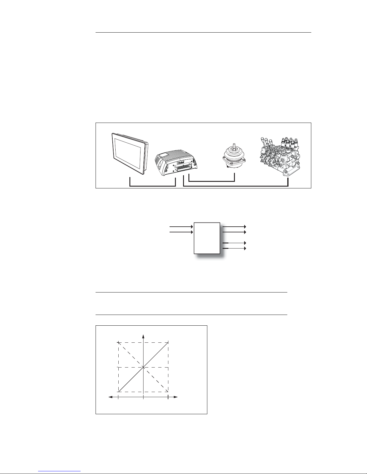
The IQAN-LC5-X05 control signals
The IQAN-LC5 is used to control the object in two directions:
• the lever is moved to the right/left, direction X +/-.
• the lever is moved forward/back, direction Y +/-.
The control signal is proportional to the lever's working range.
The control signal is transferred from the IQAN-LC5-X05 via a cable to the valve
driver electronics (i.e. IQAN-TOC2), an expansion module, or IQAN master unit.
The IQAN-LC5-X05 base has one Deutsch DTM connector, (C1), with 6 positions for
power and analogue output signals.
IQAN-LC5-X05 in a typical system
I/O overview, base
Outputs
The IQAN-LC5-X05 joystick has four (4) analogue outputs for use as command
signals..
IQAN-LC5-X05 outputs per axis.
(2) Primary analogue outputs OUT-XA and OUT-YA, 10%-90% Vs
(2) Secondary analogue outputs OUT-XB and OUT-YB, 90% - 10% Vs
CAN
Local I/O
IQAN-MD4
Expansion units
IQAN-LC5-X05 joysticks
POWER +5Vdc
OUT-YA
OUT-YB
GROUND
LC5
-X05
OUT-XA
OUT-XB
Vdc
out
90% Vs
50% Vs
10% Vs
-100%
100%
Neutral
position
Output A
Output B
Deflection
Page 9
6
MP handle
3 Product description
Instruction book, IQAN- LC5-X05
MP handle
The IQAN-LC5-X05 is designed to be used with the Multi-Purpose (MP) handle. The
MP handle together with a IQAN-LC5-X05 base will have a Deutsch DTM connector
for connection to external device (i.e., vehicle wire harness).
In order to reduce operator fatigue, the MP handle incorporates a hand rest, and is
designed for both left and right-handed use.
To extend operating life the housing is made of a corrosive-free material, and is
specially adapted for moisture drainage to protect the the system electronics. The MP
handle uses a bellow that can be quickly changed to simplify field replacement. The
cable between base and handle is routed directly through the base plate, eliminating the
risk of damage and simplifying field service, while the use of a single circuit board and
Hall effect sensors minimise the number of components and moving parts.
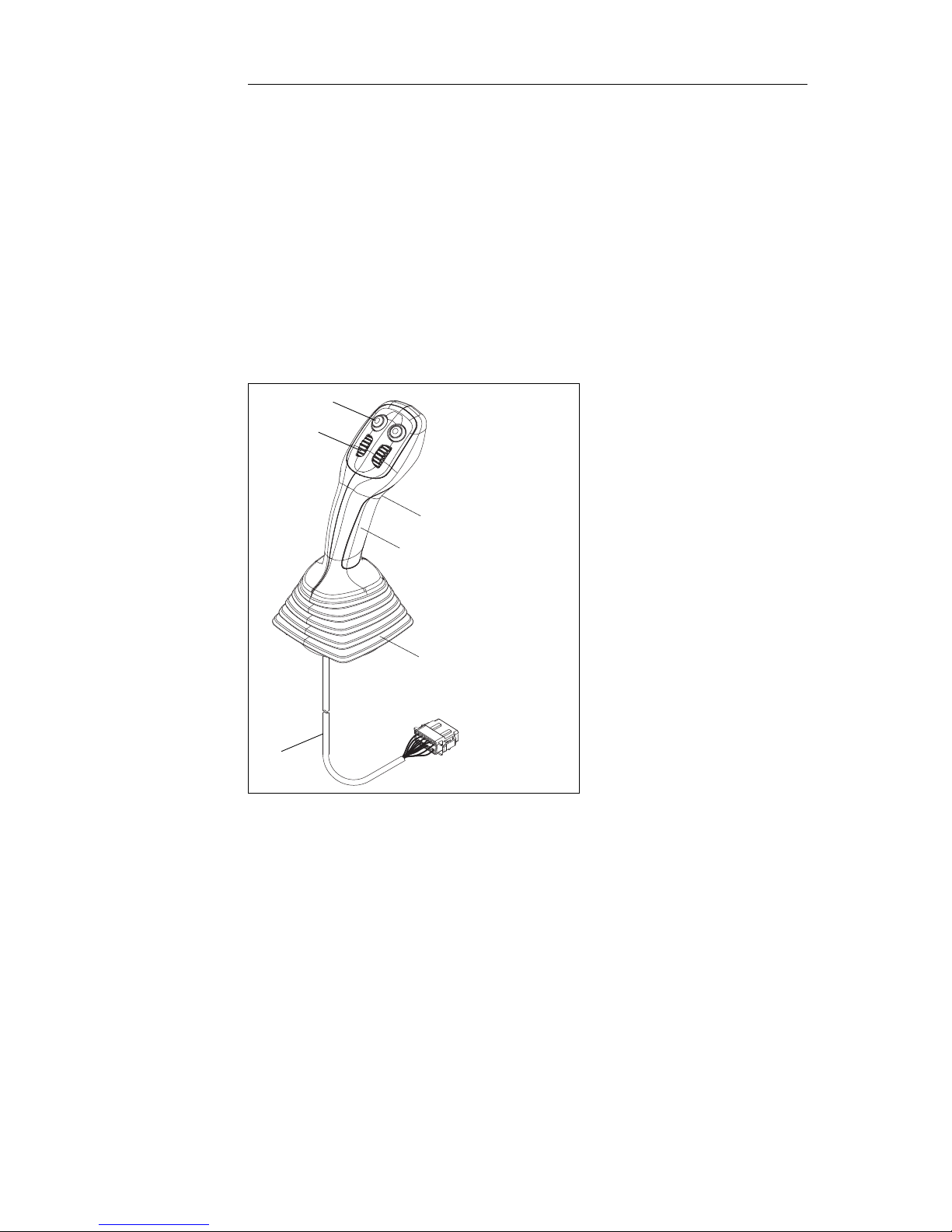
The IQAN-LC5-X05 parts.
The handle's parts
MP handle consists of:
1 Bellows, -MP handle.
2 Handle, -MPB2W2T1 shown, (other configurations are possible).
3 Momentary buttons.
4 Proportional thumbwheel (-MP handle thumbwheel has dual, mirrored outputs).
5 Momentary trigger button.
6 Cable and connector for -MP (6 pos. or 12 pos., depending on handle functions).
3
4
2
6
1
5
Page 10

7
I/O overview, MP handle
3 Product description
Instruction book, IQAN- LC5-X05
I/O overview, MP handle
Outputs
Digital
The IQAN-LC5-X05 MP handle has up to nine (9) digital outputs for use as command
signals..
Analogue
The IQAN-LC5-X05 MP handle has up to four (4) thumbwheel analogue outputs for
use as command signals..
MP handle outputs per thumbwheel.
(8) momentary button outputs B1 thru B8
(1) momentary trigger button outputs T1
(2) Primary analogue outputs OUT-W1A and OUT-W2A, 10%-90% Vs
(2) Secondary analogue outputs OUT-W1B and OUT-W2B, 90% - 10% Vs
POWER +5Vdc
OUT-W2A
OUT-W2B
GROUND
MP
OUT-W1A
OUT-W1B
B1
Bn
Vdc
out
90% Vs
50% Vs
10% Vs
-100%
100%
Neutral
position
Output A
Output B
Deflection
Page 11

8
IQAN-LC5-X05
4 Safety
Instruction book, IQAN- LC5-X05
4Safety
IQAN-LC5-X05
Redundant signals
In order to fulfill high safety demands, the analogue joystick IQAN-LC5-X05 uses dual
outputs per axis. The secondary output is the inverse or "mirror image" of the primary
output. These outputs can be compared in the controller and used to detect faults.
Use of limited signal range
The analogue outputs of the IQAN-LC5-X05 use limited signal range to provide an
additional method for error detection. The operating signal range for primary and
secondary outputs are 10%-90% Vs and 90%-10% Vs respectively. Vs (power supply)
is typically 5Vdc. This allows the controller to detect if a wire is pulled loose (open,
result 0V) or making contact with a powered wire (short, result 5V or greater).
Detecting wiring faults can protect against unintended movement.
WARNING
Risk of injury! Do not use in areas with high magnetic fields.
The IQAN-LC5-X05 is based on hall effect sensors. Exposure to high external
magnetic fields may lead to unwanted activation of the output signals.
For maximum allowed external magnetic field, see Appendix A, on page 21.
Page 12

9
Mounting the unit
5 Mounting
Instruction book, IQAN- LC5-X05
5 Mounting
Mounting the unit
NOTICE
The IQAN-LC5-X05 unit should be mounted according to the following instructions.
Mounting considerations
• The control lever must be built in so that it is protected against direct pressurized
liquid spray (above flange) and excessive mechanical forces.
• The machine manufacturer must consider the need of a protective catch, or similar,
to prevent unintentional working of the lever.
NOTICE
Take careful consideration when positioning the unit.
• Mount the unit so that it is not exposed to external heat, e.g. from the engine or
heater.
• Mount the unit so there is no risk that the harness can be folded, crushed, worn or
damaged in any way.
• Locate the harness so there is no pressure on the connector.
• Use ergonomics. The control lever should be mounted at a height so that there is no
pressure on the driver's arm and shoulders. The IQAN-LC5-X05 and a well
designed handle, such as the MP, combined with moveable arm rests, can provide
good ergonomics.
NOTICE
Do not exceed power supply limits for the joystick base and thumbwheel.
Reversed polarity, or supply voltage dif ferent from recommended operating conditions,
see Appendix A, on page 21, will seriously damage the unit.
Mounting methods
• Control lever IQAN-LC5-X05 must only be mounted using screws through the
flange.
Mounting the IQAN-LC5-X05 with screws.
4x
Page 13

10
Handle considerations
5 Mounting
Instruction book, IQAN- LC5-X05
• Allow sufficient space beneath the unit to provide for unplugging the connector.
Required space for connector.
Please refer to the IQAN-LC5-X05 installation sheet for mounting dimensions.
Handle considerations
Recommended handle specification
In addition to the MP handle, the IQAN-LC5-X05 will accept OEM specified handles.
These handles will need to be adapted to mount on the joystick stem. The maximum
weight of any handle fitted to the IQAN-LC5-X05 combined with its center of gravity
(COG), shall not cause more force than the minimum activation moment. For the
minimum activation force, see Appendix A, on page 29. Any tilting of the lever by
armrest movement or possible machine levelin g or orientation should be taken into
consideration when specifying a suitable handle.
WARNING
Risk of injury! Exceeding the recommended handle specifications could cause
unintended movement of the joystick.
Environmental specification
Any handle used with the IQAN-LC5-X05 should be a sealed type that is rated IP65 for
outdoor use. Additionally, the joystick must always have a bellow installed to ensure
that it will meet the environmental specification for sealing above the flange. When
using a handle from a different manufacturer than Parker, be sure to include a suitable
bellow made of a material that is able to withstand the stresses of outdoor use in mobile
hydraulic machinery.
NOTICE
Failure to use a properly fitted bellow of the correct material will cause the unit to not
meet its environmental specification and may result in damage to the IQAN-LC5-X05
joystick.
75
Page 14

11
Handle considerations
5 Mounting
Instruction book, IQAN- LC5-X05
Handle configuration to fit -U2 bellow
The IQAN-LC5-X05 is offered without a handle, either no bellow (-U1) is supplied, or
a standard bellow with Ø40mm opening is supplied (-U2). A handle of customer design
or from a 3rd party handle manufacturer may use this standard boot if the mounting
bushing is properly designed.
The LC5 handle mount consists of a Ø10mm stem and M12 thread, for dimensions, see
section Dimensioning of the IQAN-LC5-X05, on page 24. To fit the -U2 bellow, a disc
with a groove to hold the top of the bellow needs to be an integral part of the handle
mount.
Disc dimension guidelines for -U2 bellow interface.
Depending on the mount design, the disc may be plastic if desired, however, the
threaded part of the handle mount that is tightened to the LC5 stem should be metal for
strength.
NOTICE
The design shown above is a guideline only!
The customer is responsible for developing a suitable handle interface when mounting
a non-Parker handle to an IQAN-LC5-X05-U2 joystick base.
min Ø 18.0 (2x)
Ø 45±0.3
Ø 55±0.5
THREAD
LENGTH
min 15
Ø 10.1
M12x1.25
+0.2
-0.0
SECTION A-A
A
A
1±0.2
2±0.2
2.5±0.2
6±0.3
CUSTOMER DESIGN
R 1±0.3
Page 15

12
IQAN-LC5-X05 connector C1
6 Installation
Instruction book, IQAN- LC5-X05
6 Installation
IQAN-LC5-X05 connector C1
Connector C1 pin assignments
Connector kit Parker 20072408
Housing Deutsch no. DTM06-6S
C1
Pin type Deutsch no. 1062-20-0222
Wedge type Deutsch no. WM6S
Sealing plug Deutsch no. 0413-204-2005
Recommended
cable
0.75-1 mm
2
(18 AWG)
Symbol Pin No. Function
Power 6 Power supply Vs, +5Vdc
GND 1 Power supply ground, 0Vdc
OUT-XA 2 X primary signal, 10%-90% Vs
OUT-XB 5 X secondary signal, 90%-10% Vs
OUT-YA 3 Y primary signal, 10%-90% Vs
OUT-YB 4 Y secondary signal, 90%-10% Vs
5
4
3
2
1
6
POWER +5Vdc
OUT-YA
OUT-YB
GROUND
LC5
-X05
OUT-XA
OUT-XB
Page 16

13
G handle connector, 6 position
6 Installation
Instruction book, IQAN- LC5-X05
G handle connector, 6 position
Connector, 6 position assignments
G handle function for 6 position connector
G handle proportional rocker.
Connector parts Parker 5035017
Housing Deutsch no. DTM04-6P
C1
Pin type Deutsch no. 1060-20-0222
Wedge type Deutsch no. WM6P
Sealing plug Deutsch no. 0413-204-2005
Supplied on
handle type
G
Symbol Color
G handle
Pin No.
-Vref-B Black 1
OUT-ZA White 2
OUT-ZB Green 3
--
--
+Vref-B Red 6
1
6
POWER +5Vdc
GROUND
G
OUT-Z1
A
OUT-Z1B
Z-axis
Page 17

14
MP handle connector, 6 position
6 Installation
Instruction book, IQAN- LC5-X05
MP handle connector, 6 position
Connector, 6 position assignments
MP handle faceplate button numbering for 6 position
MP button numbering. (Note: legacy N handle 4 button numbering is different).
Connector parts Parker 5035017
Housing Deutsch no. DTM04-6P
C1
Pin type Deutsch no. 1060-20-0222
Wedge type Deutsch no. WM6P
Sealing plug Deutsch no. 0413-204-2005
Supplied on
handle types
MPB0W0T1, MPB2W0T0,
MPB2W0T1, MPB4W0T0
Symbol Color
MPB0W0T1
Pin No.
MPB2W0T0
Pin No.
MPB2W0T1
Pin No.
MPB4W0T0
Pin No.
+Vref-BRed6666
B1Grey 222
B2Green 333
B3 Brown 4
B4 Violet 5
T1 Pink 4 4
16
POWER +5Vdc
to
32 Vdc
MP
B1
Bn
B2W0T0
B2W0T1
B4W0T0
B0W0T1
1
2
2
3
1
4
Page 18

15
MP handle connector, 12 position
6 Installation
Instruction book, IQAN- LC5-X05
MP handle connector, 12 position
Connector, 12 position assignments
MP handle faceplate button numbering for 12 position
MP button numbering. (Note: legacy N handle 4 button numbering is different).
Types with thumbwheels continued in separate table.
Connector parts Parker 5035018
Housing Deutsch no. DTM04-12PA
Pin type Deutsch no. 1060-20-0222
Wedge type Deutsch no. WM12P
Sealing plug Deutsch no. 0413-204-2005
Supplied on
handle types
MPB4W0T1, MPB8W0T0,
MPB8W0T1, MPB2W2T0,
MPB2W2T1, MPB4W1T0,
MPB4W1T1
Symbol Color
MPB4W0T1
Pin No.
MPB8W0T0
Pin No.
MPB8W0T1
Pin No.
+Vref-A Red 12 12 12
B1Grey444
B2Green555
B3 Brown 6 6 6
B4 Violet 8 8 8
B5 Yellow 2 2
B6 Orange 3 3
B7 White 10 10
B8 Blue 11 11
T1 Pink 9 9
6
1
7
12
B4W0T1 B8W0T0
B8W0T1
2
3
1
4
4
5
3
6
2
7
1
8
Page 19

16
MP handle connector, 12 position
6 Installation
Instruction book, IQAN- LC5-X05
Connector, 12 position assignments
MP handle faceplate function numbering for 12 position
MP button and thumbwheel numbering.
Symbol Colour
MPB2W2T0
Pin No.
MPB2W2T1
Pin No.
MPB4W1T0
Pin No.
MPB4W1T1
Pin No.
+Vref-A Red 12 12 12 12
-Vref-ABlack1111
B1Grey4444
B2Green5555
B3 Brown 6 6
B4 Violet 8 8
T1 Pink 9 9
OUT-W1PYellow2222
OUT-W1SOrange3333
OUT-W2P White 10 10
OUT-W2S Blue 11 11
POWER +5Vdc
OUT-W2
A
OUT-W2B
GROUND
MP
OUT-W1
A
OUT-W1B
B1
Bn
Vdc
out
90% Vs
50% Vs
10% Vs
-100%
100%
Neutral
position
Output A
Output B
Deflection
B2W2T0
B2W2T1
B4W1T0
B4W1T1
2
3
1
4
1
2
1
2
1
Page 20

17
MP handle connector, 12 position
6 Installation
Instruction book, IQAN- LC5-X05
Required connectors, based on model code
Model code 20072408 5035017 5035018
IQAN-LC5-X05-U1 X - -
IQAN-LC5-X05-U2 X - -
IQAN-LC5-X05-G X X
IQAN-LC5-X05-MPB0W0T0 X - -
IQAN-LC5-X05-MPB0W0T1 X X -
IQAN-LC5-X05-MPB2W0T0 X X -
IQAN-LC5-X05-MPB2W0T1 X X -
IQAN-LC5-X05-MPB4W0T0 X X -
IQAN-LC5-X05-MPB4W0T1 X - X
IQAN-LC5-X05-MPB8W0T0 X - X
IQAN-LC5-X05-MPB8W0T1 X - X
IQAN-LC5-X05-MPB4W1T0 X - X
IQAN-LC5-X05-MPB4W1T1 X - X
IQAN-LC5-X05-MPB2W2T0 X - X
IQAN-LC5-X05-MPB2W2T1 X - X
Page 21

18
Supply voltage
6 Installation
Instruction book, IQAN- LC5-X05
Supply voltage
WARNING
Before any installation of an IQAN system can take place, make sure the ignition lock
is turned off and the battery is disconnected.
Emergency stop
Make sure an Emergency Stop disconnecting the system power supply, is easily
accessible at any time. The IQAN module and standalone controller instruction books
show how to connect an emergency stop.
Connecting of supply voltage, expansion module
The supply voltage, should be within the operating range, see Appendix A, on page 21 .
Connect the supply voltage to POWER +5Vdc, pin C1:6. The regulated 5Vdc is
supplied from an IQAN module’s +VREF. The ground connection is made from GND
pin C1:1 to the IQAN module’s -VREF.
NOTICE
Maximum load for the VREF position is different between types of IQAN modules.
Refer to the appropriate instruction book.
EXAMPLE
Connecting an IQAN-LC5-X05 to expansion module.
+5 Vdc
GND
IQAN module
+VREF
-VREF
LC5-X05
Page 22

19
Output signals
6 Installation
Instruction book, IQAN- LC5-X05
Output signals
Primary and secondary outputs
The IQAN-LC5-X05 has dual outputs for each axis. The redundant outputs allow the
user to set up controller logic that monitors the integrity of the dual joystick signals.
The secondary signal for each axis is a mirror of the primary signal. Use of the
secondary output is optional and determined by the user’s requirements.
Connecting of IQAN-LC5-X05 outputs
When you connect the IQAN-LC5-X05 joystick to a module or standalone controller,
you may use both OUT-[axis]A and OUT-[axis]B signals from the joystick. The
primary signal for the axis is connected to a VIN, voltage input and the secondary
signal for the axis, if used, is connected to a separate VIN on the controller module.
Connect each primary axis 10%-90% Vs output signal to VIN, and optionally connect
the corresponding secondary axis 90%-10% Vs output signal to another VIN.
WARNING
The previous example is presented with limited information to explain the use of
primary and secondary signals from the IQAN-LC5-X05. Safety considerations such as
the use of an ’operator present’ switch to enable outputs etc. are always recommended.
EXAMPLE
Connecting an IQAN-LC5-X05 to a module.
to valve section controlled
to valve section controlled
OUT-YB(optional)
OUT-XB(optional)
OUT-XA
OUT-YA
by Y axis of joystick
by X axis of joystick
IQAN module
LC5-X05
VIN
VIN
VIN
VIN
Page 23

20
Output signals
6 Installation
Instruction book, IQAN- LC5-X05
Connecting of -MP handle outputs
When you connect the IQAN-LC5-X05 joystick handle functions to a module or
standalone controller you may have proportional outputs from thumbwheels, or on-off
outputs from buttons. For the proportional outputs, you may use both OUT-A and
OUT -B signals from the thumbwheels. The primary signal for the axis is connected to a
VIN, voltage input and the secondary signal for the axis, if used, is connected to a
separate VIN on the controller module.
Connect each primary output 10%-90% Vs output signal to VIN, and optionally
connect the corresponding secondary output 90%-10% Vs output signal to another
VIN.
WARNING
The previous example is presented with limited information to explain the use of
primary and secondary signals from the -MP handle thumbwheels. Safety
considerations such as the use of an ’operator present’ switch to enable outputs etc. are
always recommended.
EXAMPLE
Connecting -MP thumbwheel outputs to a module.
to valve section controlled
to valve section controlled
OUT-W1B (optional)
OUT-W2B (optional)
OUT-W1A
OUT-W2A
by thumbwheel 2 of joystick
by thumbwheel 1 of joystick
IQAN module
MP handle
VIN
VIN
VIN
VIN
Page 24

21
IQAN-LC5-X05 Technical Overview
Appendix A
Instruction book, IQAN-LC5-X05
Appendix A
IQAN-LC5-X05 Technical Overview
IQAN-LC5-X05, base and -MP handle
Absolute Maximum Ratings
a
a.The “Absolute Maximum Ratings” table lists the maximum limits to which the device can be subjected without damage. This doesn´t
imply that the device will function at these extreme conditions, only that, when these conditions are removed and the device operated
within the “Recommended Operating Conditions”, it will still be functional and its useful life won’t have been shortened.
Param eter
Limit values
Unit Remark
min. typ. max.
Ambient temperature, T
A
Storage temperature
– 40
– 40
+85
+100
°C
Maximum over voltage on any pin 8.5 V
External magnetic fields 2.5 mT Risk for exceeding maxi-
mum difference on output
signal from ideal value.
Environmental ratings
Parameter Remark
EMI
ISO 13766/ISO 14982, radiated emission
ISO 11452-4:2005, conducted susceptability
ISO 11452-2:2004, radiated susceptability
ISO 7637-3:2007, conducted transients susceptability
30 - 1000 MHz
1 -200 MHz, 1 KHz, 80%AM, 100 mA
200 -2000 MHz, 1 KHz, 80%AM, 100 V/m
Level 3
ESD
ISO 10605:2001, ESD, operation
ISO 10605:2001, ESD, operation
ISO 10605:2001, ESD, handling
15kV air
8 kV contact
4 kV contact
Mechanical environment
IEC 60068-2-64:1993 Fh, random vibration
IEC 60068-2-29:1987 Eb, bump
15-1000 Hz, 11.6 grms, 3 x10 hours
40g, 6 ms, 1000 x 6 directions
Climate environment
IEC 600529:2001 IP65, (with sealed handle and bellow)
IEC 60068-2-52:1996 Kb, salt mist
IEC 60068-2-30:1985 Db, damp heat, cyclic
IEC 60068-2-78:2001, damp heat, steady state
IEC 60068-2-2:1993-01 Bb, heat, operation
IEC 60068-2-2:1993-01 Bb, heat, storage
IEC 60068-2-1:1993-02 Ab, cold
IEC 60068-2-14:1984 Nb, change of temperature
12.5 l/minute, 3 minutes
72 hours
+55°C, 95% RH, 6 cycles
+40°C, 93% RH, 21 days
+70°C, 72 hours
+100°C, 72 hours
-40°C, 16 hours
-30°C to +85°C, 100 x 4 hours
Page 25

22
IQAN-LC5-X05 Technical Overview
Appendix A
Instruction book, IQAN-LC5-X05
IQAN-LC5-X05, base
System
TA = -40 to +85 °C, unless otherwise specified
Param eter
Limit values
Unit Remark
min. typ. max.
Weight, base unit
Weight, base unit + MP handle
380
750
g
Ambient temperature, T
ROC
– 40 +85 °C recommended operating
Voltage supply, V
S
4.55.05.5V
Current consumption, base only 33 46 mA V
S
= 5.0 V
Electrical characteristics
Param eter
Limit values
Unit Remark
min. typ. max.
Number of VOUT 4 antivalent signals
VOUT, minimum position 400 500 600 mV over life of unit
VOUT, center position 2400 2500 2600 mV over life of unit
VOUT, maximum position 4400 4500 4600 mV over life of unit
VOUT linearity error 300 mV Max difference on output
signal A or B from ideal
VOUT A and B difference 375 mV Max difference between
output signals A/B
VOUT resolution 12 bits =1.22 mV
Response time 6 ms
Load, resistive 4.5 kohm
Load, capacitive 1 µF
Continuous voltage 5.5 V
Protection SCG
Mechanical ratings
Param eter
Limit values
Unit Remark
min. typ. max.
Angle of movement ±18 deg.
Deflection moment, neutral 0.6 Nm
Deflection moment, fully actuated 1.4 Nm
One time loading 100 Nm Exceptional condition
Expected life
5x10
6
cycles One cycle: Neutral to full +
direction to neutral to full direction and back to neutral
Page 26

23
IQAN-LC5-X05 Technical Overview
Appendix A
Instruction book, IQAN-LC5-X05
IQAN-LC5-X05, -MP handle
Thumbwheel
Electrical characteristics
Param eter
Limit values
Unit Remark
min. typ. max.
Number of VOUT 2 antivalent signals
VOUT minimum position 400 500 600 V V
S
= 5.0 V
VOUT center position 2400 2500 2600 V V
S
= 5.0 V
VOUT maximum position 4400 4500 4600 V V
S
= 5.0 V
VOUT linearity error 300 mV Max difference on output
signal A or B from ideal
VOUT A and B difference 375 mV Max difference between
output signal A/B
VOUT resolution 12 bits =1.22 mV
Response time 6 ms
Load, resistive 4.5 kohm
Load, capacitive 1 µF
Continuous voltage 5.5 V
Current supply, per thumbwheel 16 23 mA Vs=5,0V,
Protection SCG
Mechanical ratings
Param eter
Limit values
Unit Remark
min. typ. max.
Angle of movement ±25 deg.
Deflection moment, neutral 10 Nmm
Deflection moment, fully actuated 15 Nmm
Expected life
5x10
6
cycles One cycle: Neutral to full +
direction to neutral to full direction and back to neutral
Buttons
Param eter
Limit values
Unit Remark
min. typ. max.
Max current 400
100
mA 32 VAC, resistive load
50 VDC, resistive load
Total travel 1.5 mm
Switching point 1.2 mm
Expected life
.5x10
6
cycles electrical
Mechanical life
1x10
6
cycles
Operating force 2 5 N activation
Page 27

24
Dimensioning of the IQAN-LC5-X05
Appendix B
Instruction book, IQAN-LC5-X05
Appendix B
Dimensioning of the IQAN-LC5-X05
90
105
105
49
80
Ø 6 (8x)
80
M12 x 1.25
(Ø 108)
Alternative mounting holes
28
10
12
158
unit = mm
stem detail
G handle
Page 28

25
Dimensioning of the IQAN-LC5-X05
Appendix B
Instruction book, IQAN-LC5-X05
101
240
unit = mm
-MP handle
Page 29

For latest information visit our website www.iqan.com
Information in this instructionbook is subject to change without notice
Parker Hannifin
Electronic Controls Division
SE-435 35 Mölnlycke
Sweden
Tel +46 31 750 44 00
Fax +46 31 750 44 21
www.parker.com/ecd
Parker Hannifin
Electronic Controls Division
1651 N. Main Street
Morton, IL 61550
USA
Tel +1 309 266 2200
Fax +1 309 266 6674
Publ no HY33-8402-IB/UK
Edition 2016-08-09
 Loading...