

Page 1
3
corpuls
User Manual
Page 2

Contents User Manual corpuls
3
ii ENG - Version 2.1 – P/N 04130.2
Page 3

User Manual corpuls
3
Contents
This user manual has been compiled to provide users with information
necessary for safe and trouble-free operation, use on patients and maintenance
3
of corpuls
. All persons dealing with use, maintenance and troubleshooting
must read and implement this user manual.
In addition to this user manual, the currently applicable ordinances and the
generally accepted engineering principles as well as regulations for
occupational health and safety and accident prevention must be complied with.
The corpuls
"Medical Device Directive 93/42/EC of the Commission". The corpuls
3
complies with the basic standards as specified in Annex I of the
3
is a
medical product class IIb. In the UMDNS (Universal Medical Device
Nomenclature System) the corpuls
3
has the code 17-882.
GS Elektromedizinische Geräte
G. Stemple GmbH
Hauswiesenstrasse 26
86916 Kaufering
Germany
All rights reserved, particularly rights of reproduction and distributi on, in additi on to translation.
Technical modifications, errors or printing mistakes reserved.
The rights to the trademarks and registered trademarks remain with the originators and holders of
the respective trademarks.
No part of the user manual may be reproduced,
electronic systems in any form whatsoever without the written agreement of GS Elektromedizinische
Geräte G. Stemple GmbH.
ENG - Version 2.1 – P/N 04130.2 iii
saved, processed, copied or circulated by means of
Page 4

Contents User Manual corpuls
Address of the sales and service partner
Service address
In case of enquiries, please contact:
3
Information on the authorised service and sales partners can also be found on
the following website:
www.corpuls.com
iv ENG - Version 2.1 – P/N 04130.2
Page 5

User Manual corpuls
3
3
Contents
Versions of the corpuls3 user manual
Issue Date User manual version Software version
1 06/2007 ENG V1.1 – 04130.2 1.1.0
2 08/2007 ENG V1.2 – 04130.2 1.2.0
3 11/2007 ENG V1.3 – 04130.2 1.3.0
4 07/2008 ENG V1.4 – 04130.2 1.4.1
5 07/2009 ENG V1.5 – 04130.2 1.5.0
6 12/2009 ENG V1.6 – 04130.2 1.6.0
7 11/2010 ENG V1.7 – 04130.2 1.7.0
8 07/2011 ENG V1.8 – 04130.2 1.8.0
9 10/2011 ENG V1.9 – 04130.2 1.9.0
10 07/2012 ENG V2.0 – 04130.2 2.0.0
11 06/2013 ENG V2.1 – 04130.2 2.1.0
Versions of the supplements
to the user manual corpuls
Version Date Description Version
A 04/2010 Supplement of
the alarm
messages
A 06/2010 New Defibrillator
Keyboard
A 03/2011 Interval
Measurement
NIBP
A 07/2011 NVG mode EN V1.8 – 04130.2 1.8.0
user manual
EN V1.4 - 04130.2
EN V1.5 - 04130.2
EN V1.6 - 04130.2
EN V1.7 - 04130.2 1.7.0
EN V1.7 - 04130.2 1.7.2
Version
Software
1.4
1.5
1.6
ENG - Version 2.1 – P/N 04130.2 v
Page 6

Contents User Manual corpuls
Contents
Safety ................................................................................................... 1
1
1.1 General ........................................................................................... 1
1.2 Operating Staff ................................................................................ 1
1.2.1 Restrictions of Therapeutic Functions ....................................... 1
1.2.2 Maintenance .............................................................................. 2
1.3 Information and Warning Labels on the Device .............................. 2
1.4 Warning Notices and Symbols ........................................................ 3
1.5 Special Types of Risk ..................................................................... 3
2 Intended Use ....................................................................................... 4
3 Introduction ........................................................................................ 6
3.1 Components .................................................................................... 6
3.2 Device Design ................................................................................. 8
3.2.1 Pairing (Connection Authorisation) .......................................... 10
3.2.2 Monitoring Unit ......................................................................... 12
3.2.3 Patient Box and Accessory Bag .............................................. 14
3.2.4 Defibrillator/Pacer .................................................................... 17
3.2.5 Defibrillator/Pacer SLIM ........................................................... 18
3.2.6 Brackets ................................................................................... 19
3.3 Description of the Monitoring, Diagnostic and Therapeutic
Functions ....................................................................................... 20
3.3.1 Monitoring and Diagnostic F unctio ns ....................................... 20
3.3.2 Therapeutic Functions ............................................................. 21
3.4 Alarm management ....................................................................... 23
3.4.1 Alarm Signals at the Monitoring unit ........................................ 24
3.4.2 Alarm Signals at the Patient box .............................................. 26
3.5 Energy Management ..................................................................... 27
3.5.1 Battery Operation ..................................................................... 27
3.5.2 Mains Operation ....................................................................... 29
3
4 General Operating Instructions ...................................................... 31
4.1 Operating and Display Elements .................................................. 31
4.1.1 Operating Elements and LEDs on the Monitoring Unit ............ 31
4.1.2 Basic Structure of the Display Pages on the
Monitoring Unit ......................................................................... 35
4.1.3 Patient Box Display .................................................................. 39
4.1.4 Control Keys and LEDs on the Patient Box ............................. 40
4.1.5 Control Key and LEDs on the Defibrillator/Pacer .................... 41
4.1.6 Control Key and LEDs on the Defibrillator /Pac er SLI M ........... 42
4.2 Switching On and Off .................................................................... 43
4.2.1 Switching On ............................................................................ 43
4.2.2 Switching Off ............................................................................ 44
vi ENG - Version 2.1 – P/N 04130.2
Page 7

User Manual corpuls
3
Contents
4.3 Menu Control ................................................................................. 46
4.3.1 Softkey Context Menu.............................................................. 46
4.3.2 Parameter Context Menu and Curve Context Menu ............... 47
4.3.3 Main Menu ............................................................................... 49
4.3.4 Configuration Dialogue ............................................................ 50
4.4 Disconnecting and Connecting Modules ...................................... 51
4.4.1 Disconnecting the Monitoring Unit from the
Defibrillator/Pacer .................................................................... 51
4.4.2 Disconnecting the Patient Box from the Monitoring
Unit ........................................................................................... 52
4.4.3 Connecting the Patient Box to the Monitoring Unit .................. 53
4.4.4 Connecting the Monitoring Unit to the
Defibrillator/Pacer .................................................................... 54
4.4.5 Removing the Patient Box from the Compact Device ............. 55
4.5 Accessory Bag .............................................................................. 56
4.5.1 Fitting the Accessory Bag ........................................................ 56
4.5.2 Packing the Accessory Bag ..................................................... 57
4.6 Inserting the Device into the Brackets .......................................... 60
4.6.1 Defibrillator/Compact Device Bracket ...................................... 60
4.6.2 Monitoring Unit Bracket............................................................ 61
4.6.3 Patient Box Charging Bracket .................................................. 62
5 Operation – Therapy ........................................................................ 63
5.1 Therapy Electrodes for Defibrillation and Pacing .......................... 63
5.1.1 Types of Therapy Electrodes ................................................... 63
5.1.2 Connecting the Electrode Cable .............................................. 65
5.1.3 Removing the Shock Paddles from their Holders and
Re-inserting them ..................................................................... 66
5.2 Preparing the Patient for Defibrillation, Cardioversion and
Pacer Therapy............................................................................... 67
5.3 Defibrillation in AED Mode ............................................................ 68
5.3.1 Information on the AED Mo de ................................................. 68
5.3.2 Defibrillation in AED mode with corPatch Electrodes ........... 70
5.3.3 Defibrillation in AED Mode with Shock Paddles ...................... 71
5.4 Manual Defibrillation and Cardioversion ....................................... 74
5.4.1 Information on Manual Defibrillation and
Cardioversion ........................................................................... 74
5.4.2 Manual Defibrillation with corPatch Electrodes .................... 76
5.4.3 Manual Defibrillation and C ardio vers i on with Sh ock
Paddles .................................................................................... 77
5.4.4 Manual Defibrillation and C ardio vers i on with Sh ock
Spoons ..................................................................................... 79
5.4.5 Manual Defibrillation and C ardio vers i on of Neona tes
and Children ............................................................................. 80
5.5 External Pacer............................................................................... 81
5.5.1 Information on the External Pacer ........................................... 81
5.5.2 Preparing the pacer function .................................................... 83
ENG - Version 2.1 – P/N 04130.2 vii
Page 8

Contents User Manual corpuls
5.5.3 Starting the Pacer Function ..................................................... 85
5.6 Metronome .................................................................................... 89
5.6.1 Information on the Metronome ................................................. 89
5.6.2 Starting the Metronome ........................................................... 90
5.7 CPR Feedback .............................................................................. 91
5.7.1 Information on CPR Feedback ................................................ 91
5.7.2 Preparing CPR Feedback ........................................................ 93
5.7.3 Working with CPR Feedback ................................................... 94
6 Operation – Monitoring and Diagnosis .......................................... 95
6.1 Information on Monitoring and Diagnosis ..................................... 95
6.2 ECG Monitoring............................................................................. 95
6.2.1 Information on ECG Monitoring ............................................... 95
6.2.2 ECG Lead Colour Coding ........................................................ 96
6.2.3 Preparing ECG Monitoring ....................................................... 97
6.2.4 Performing ECG Monitoring ..................................................... 98
6.2.5 Adapting the Representation of the ECG Curve .................... 100
6.2.6 Heart Rate Monitoring ............................................................ 102
6.3 Recording, Measuring, Printing and Interpreting a
Diagnostic ECG........................................................................... 102
6.3.1 Information on Diagnostic ECG ............................................. 102
6.3.2 Preparing the Patient for a D-ECG ........................................ 103
6.3.3 Recording and Measuring a Diagnostic ECG ........................ 106
6.3.4 Representative Cycle ............................................................. 111
6.4 Longterm ECG ............................................................................ 113
6.4.1 Information on Longterm ECG ............................................... 113
6.4.2 Preparing Longterm ECG ...................................................... 114
6.4.3 Performing Longterm ECG .................................................... 114
6.5 Oximetry Monitoring (Option) ...................................................... 115
6.5.1 Information on Oximetry Monitoring ....................................... 115
6.5.2 Preparing Oximetry Monitoring .............................................. 117
6.5.3 Performing Oximetry Measurement ....................................... 118
6.5.4 Adjusting the Representation of the Oximetry
Parameters ............................................................................ 120
6.5.5 Monitoring Pulse Rate and Perfusion Index .......................... 120
6.6 CO2 Monitoring (option) .............................................................. 121
6.6.1 Information on CO2 Monitoring .............................................. 121
6.6.2 Preparing CO2 Monitoring ...................................................... 122
6.6.3 Performing CO2 Measurement............................................... 124
6.6.4 Adjusting the Representation of the CO2 Values ................... 125
6.6.5 Monitoring Respiratory Rate .................................................. 125
6.7 Non-invasive Blood Pressure Monitoring (option) ...................... 126
6.7.1 Information on NIBP Monitoring ............................................. 126
6.7.2 Preparing Blood Pressure Monitoring .................................... 129
6.7.3 Performing Individual Blood Pressure Measurement ............ 129
3
viii ENG - Version 2.1 – P/N 04130.2
Page 9

User Manual corpuls
3
Contents
6.7.4 Performing Blood Pressure Interval Monitoring ..................... 131
6.8 Invasive Blood Pressure Monitoring (Option) ............................. 131
6.8.1 Information on IBP Monitoring ............................................... 131
6.8.2 Preparing Invasive Blood Pressure Monitoring ..................... 132
6.8.3 Performing Invasive Blood Pressure Monitoring ................... 134
6.9 Temperature Monitoring (Option) ................................................ 135
6.9.1 Information on Temperature Monitoring ................................ 135
6.9.2 Preparing Temperature Monitoring ........................................ 135
6.9.3 Performing Temperature Monitoring ...................................... 136
7 Configuration .................................................................................. 137
7.1 Configuring the System ............................................................... 137
7.1.1 General System Settings ....................................................... 137
7.1.2 Display Configuration ............................................................. 140
7.1.3 Printer settings ....................................................................... 143
7.1.4 Configuration of the Fax Transmission (Default User) .......... 148
7.2 Configuration of the Monitoring Functions .................................. 148
7.2.1 ECG Monitoring ..................................................................... 148
7.2.2 Oximetry ................................................................................. 150
7.2.3 CO2 ........................................................................................ 151
7.2.4 IBP ......................................................................................... 152
7.2.5 CPR Feedback ....................................................................... 154
7.3 Alarm Configuration .................................................................... 155
7.3.1 Configuring Alarm Settings .................................................... 155
7.3.2 Configuring Alarm Settings .................................................... 156
7.3.3 Setting Alarm Limits for Monitoring Functions
Manually ................................................................................. 156
7.3.4 Setting the Alarm Limits for Monitoring Functions
Automatically .......................................................................... 158
7.4 Advanced Settings (Persons Responsible for the Device) ........ 159
7.4.1 Authorisation for Persons Responsible for the Device .......... 159
7.4.2 General System Settings (Person responsible for the
device) ................................................................................... 160
7.4.3 Configuration of the Defibrillation Function (Persons
Responsible for the Device) ................................................... 163
7.4.4 Filter Settings (Persons Responsible for the Device) ............ 165
7.4.5 Alarm Configuration (Persons Responsible for the
Device) ................................................................................... 166
7.4.6 Basic Configuration of the Views (Persons
Responsible for the Device) ................................................... 168
7.4.7 Configuration of Master Data (Persons Responsible
for the Device) ........................................................................ 169
7.4.8 Configuration of Telemetry (Persons Responsible for
the Device) ............................................................................. 170
7.4.9 Bluetooth® data interface (Persons Responsible for
the Device) ............................................................................. 177
ENG - Version 2.1 – P/N 04130.2 ix
Page 10

Contents User Manual corpuls
7.4.10 Configuration of ECG Measurement and ECG
Interpretation (Persons Responsible for the Device) ............. 179
7.4.11 Demo Mode (Persons Responsible for the Device) .............. 181
7.4.12 Data Protection Settings (Persons responsible for the
device) ................................................................................... 182
7.4.13 Configuration of the Metronome (Persons
Responsible for the Device) ................................................... 183
7.4.14 Configuration of Non-I nv as i ve Blood Pres s ure
Measurement (NIBP) (Persons Responsible for the
Device) ................................................................................... 184
8 Data Management .......................................................................... 186
8.1 Creating a Patient File ................................................................ 186
8.2 Event Key .................................................................................... 187
8.3 Handling Data ............................................................................. 187
8.4 Master Data ................................................................................. 188
8.5 Browser Key ................................................................................ 189
8.5.1 Protocol .................................................................................. 189
8.5.2 Mission Browser ..................................................................... 192
8.6 Analysis of the Data with corView2 ............................................. 193
8.7 Screenshot .................................................................................. 194
8.8 Telemetry (Option) ...................................................................... 194
8.8.1 Installing the SIM Card........................................................... 196
8.8.2 Starting Fax Transmission ..................................................... 196
8.8.3 Starting Live Data transmission with corpuls.web ............ 198
8.9 Bluetooth® data interface ............................................................ 199
8.9.1 Establishing and interrupting a Bluetooth® connection ......... 201
8.10 Insurance card reader (option) .................................................... 202
8.10.1 Data Transmission via Bluetooth® ......................................... 204
8.11 Insurance card reader (Option) ................................................... 204
3
9 Maintenance and Tests .................................................................. 206
9.1 General Information .................................................................... 206
9.2 Function Checks ......................................................................... 207
9.2.1 Function check of the Device ................................................. 208
9.2.2 Function check of the Power Supply ..................................... 213
9.2.3 Checking Accessories and Consumables ............................. 213
9.3 Automatic Self Test ..................................................................... 215
9.4 Regular Maintenance Work ........................................................ 215
9.4.1 Safety-related Checks............................................................ 215
9.4.2 Metrological Check ................................................................ 216
9.4.3 Repair and Service ................................................................ 216
9.5 Loading the Printer Paper ........................................................... 217
9.6 Changing the Battery .................................................................. 218
9.7 Cleaning, Disinfection and Sterilisat io n ...................................... 219
x ENG - Version 2.1 – P/N 04130.2
Page 11

User Manual corpuls
3
Contents
9.7.1 Monitoring Unit, Patient Box and Defibrillator/Pacer ............. 219
9.7.2 Shock Paddles ....................................................................... 221
9.7.3 Therapy Master Cable ........................................................... 222
9.7.4 Cables for Monitoring Functions ............................................ 222
9.7.5 Oximetry Sensor .................................................................... 222
9.7.6 CO2 Sensor ............................................................................ 223
9.7.7 NIBP Cuffs ............................................................................. 223
9.7.8 IBP Transducer Cable............................................................ 223
9.7.9 Temperature Sensor .............................................................. 223
9.7.10 Accessory Bag and Carrying Strap ........................................ 223
9.8 Approved Accessories, Spare Parts and Consumables ............. 224
10 Procedure in Case of Malfunctions .............................................. 233
10.1 Device alarms ............................................................................. 233
10.2 Troubleshooting and Corrective Actions ..................................... 250
10.3 Notifications Message Line and Inf ormation in the
Protocol ....................................................................................... 263
Appendix ........................................................................................................ 272
A Symbols ...................................................................................... 272
B Function Checklist ....................................................................... 277
C Factory Settings .......................................................................... 278
D Technical Specifications ............................................................. 286
E Biphasic Defibrillator ................................................................... 300
F Saf et y Information ....................................................................... 303
G ECG Analysis during Sem i-automatic Defibrillation (AED
mode) .......................................................................................... 307
H corpuls3 HYPERBARIC (HBO) ................................................... 310
I Guidelines and Manufacturer’s Declaration ................................ 311
J Warranty ...................................................................................... 316
K Protection Rights and Patents .................................................... 317
L Disposal of the Device and Acc ess or ies ..................................... 318
M Note on Data Protection .............................................................. 319
N List of Illustrations ....................................................................... 320
O List of Tables ............................................................................... 325
Index 328
ENG - Version 2.1 – P/N 04130.2 xi
Page 12

Contents User Manual corpuls
Operating instruction/
Conventions
The following conventions app l y in this user m anual:
3
Key
Key on monitoring unit, patient box and
defibrillator/pacer
[Softkey] Softkey on the monitoring unit
"Menu item" ► "Submenu item" Menu items of the main menu and
parameter and curve context menus
"Alarm message" Messages for physiological and
technical alarms on the monitoring unit
and patient box
VERBAL MESSAGE Spoken operating instructions and
alarm messages in the AED mode
Operating instructions and i nf ormation
information
in the message line of the monitoring
unit
xii ENG - Version 2.1 – P/N 04130.2
Page 13

User Manual corpuls
Instructing
person
Refresher
courses in
therapeutic use
Hyperbaric
en therapy
oxyg
3
Safety
1 Safety
1.1 General
The corpuls
• in technically perfect condition;
• used as intended (see chapter 2 Intended Use, p. 4);
• the instructions of this user manual are followed.
Malfunctions must be eliminated immediately (see chapter 10 Pr oce dur e in
Case of Malfunctions, page 233).
For the product variant corpuls
Appendix H corpuls3 HYPERBARIC (HBO).
3
may only be operated if:
3
HYPERBARIC please read and understand
1.2 Operating Staff
The corpuls
hospitals, doctor’s offices and emergency medical services, as well as of
authorities and public safety organisations.
The qualified staff must be
• trained in proper handling, use and operation of the device and of the
approved accessories as well as be
• trained in basic and advanced resuscitatory measures (BLS and ALS).
The initial instruction and training on the device must be performed by the
manufacturer or by authorised personnel.
1.2.1 Restrictions of Therapeutic Functions
Use of the therapeutic functions (defibrillation, cardioversion and pacing) is
restricted to qualified and authorised staff.
The manufacturer recommends that persons who use the therapeutic functions
of the device should take part in refresher courses regularly. The operating
company/operator is responsible for offering such refresher courses.
3
may only be operated by trained medical staff of for example
ENG - Version 2.1 – P/N 04130.2 1
Page 14
Intended Use
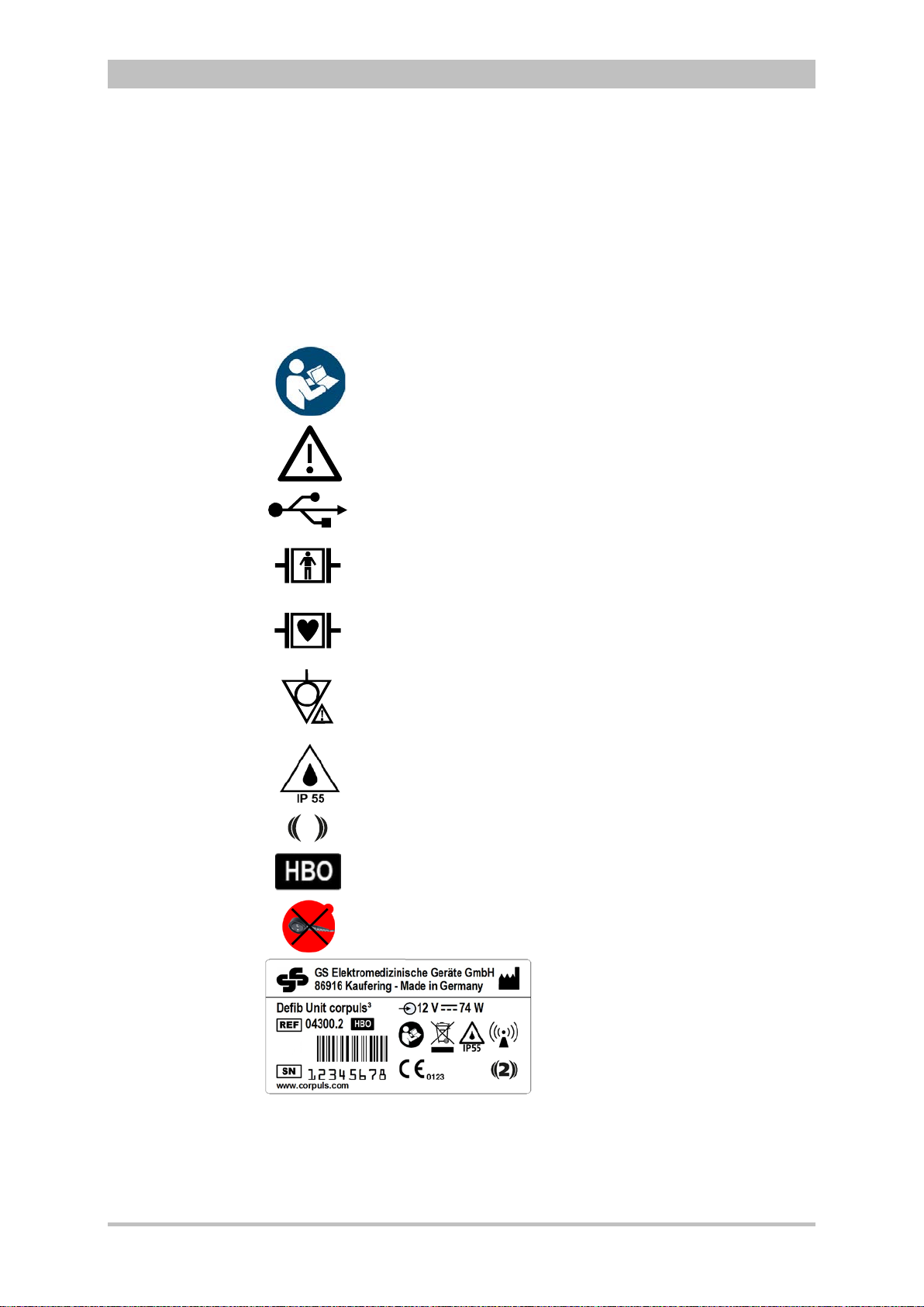
Please read and follow the instructions in the user manual
Please read the additiona
USB interface (Devices up to 09/2010)
BF (body floating, defibrillation
An isolated application
external and internal use on the patient
CF (cardiac floating, defibrillation
An isolated application component of this type is approved for use
on
Equipotential bonding
Protection class IP55
2
Symbol for second generation of radio module.
Approved for operation in a multiplace hyperbaric chamber for
hyperbaric oxygen therapy (HBO) (option).
MagCode connector is
chamber for hyperbaric oxygen therapy (HBO).
1.2.2 Maintenance
Maintenance work may only be performed by persons who are appropriately
trained and authorised by the manufacturer. Failure to observe this will result in
invalidation of claims under the warranty.
1.3 Information and Warning Labels on the Device
User Manual corpuls
l instructions in the user manual
3
the patient or patient’s heart
-proof):
component of this type is approved for
-proof):
NOT approved for operation in a hyperbaric
Fig. 1-1 Sample rating plate
2 ENG - Version 2.1 – P/N 04130.2
Page 15

User Manual corpuls
Electric shock
EMC
Note
Warning
Caution
3
Safety
1.4 Warning Notices and Symbols
A number of actions during the operation of the corpuls
patients, users and third parties.
Such actions are indicated by warni ng not ices in this user manual.
The following symbols are used:
"Warning" denotes a dangerous situation.
If the warning is not heeded, extremely severe injuries or substantial material
damage may occur.
"Caution" denotes a possibly dangerous situation.
If not heeded, minor injuries or slight material damage may occur.
These paragraphs contain information which must be read and understood.
3
carry risks for
1.5 Special Types of Risk
The defibrillator emits powerful electrical energy. Severe injuries or death may
result if the defibrillator is not used in accordance with this user manual.
• Familiarise yourself with the device and this user manual.
The defibrillator must not be opened. Internal components may carry high
voltages.
• If a fault is suspected, have the device checked by the authorised sales
and service partner and, if necessary, repaired.
The defibrillator may cause electromagnetic interference, particularly during
charging and on triggering the defibrillation shock.
The functioning of devices operated in the vicinity may be compromised.
• Check the effects of the defibrillator on other devices, preferably before
an emergency occurs.
Electromagnetic fields of other devices may invalidate the ECG readings.
ECG analysis may be impaired. It may be impossible to trigger a defibrillation
shock or pacer pulse.
• Please read and follow the instructions for operation of the device in
chapter 2 Intended Use, p. 4 in addition to the safety warnings during use
It is essential to read and follow the safety information in the appendix F (from
page 272).
.
ENG - Version 2.1 – P/N 04130.2 3
Page 16

Intended use
2 Intended Use
The corpuls3 is intended
• for measurement and monitoring of vital functions in addition to
• defibrillation, cardioversion or cardiac pacing
of patients in the preclinical and clinical field by qualified medical staff trained in
the use of the device.
The following monitoring functions are available:
• ECG
• diagnostic ECG
Optional:
• oximetry (SpO
2,
• capnometry (CO
• temperature (T)
• non-invasive blood pressure monitoring (NIBP)
• invasive blood pressure monitoring (IBP)
The corpuls
3
is approved for monitoring in operating diagnostic X-ray units
(e. g. computed tomography). Exempt from this is the oximetry option, because
measured values might be falsified. When equipped with the HBO (hyperbaric
oxygen therapy) option, the corpuls
hyperbaric chamber up to 3 barg and an oxygen concentration of < 23%.
Intended use of corpuls
• approved by the manufacturer (see chapter 9.8 Approved Accessories,
Spare Parts and Consumables, p. 224) and
• appropriate for the function and patient.
Use of accessories on corpuls
is not considered to be intended use.
®,
SpCO
)
2
SpHb, SpMet®)
3
is approved for operation in a multiplace
3
includes employment of accessories which are
3
which are not approved by the manufacturer
4
Warning
Defibrillation protection for patients, user and third parties cannot be
guaranteed, if accessories other than those authorised by the manufacturer
are used.
The therapeutic functions of defibrillation, cardioversion and pacer must only be
performed with constant monitoring of the patient.
Performing the therapeutic functions without eye contact with the patient is not
considered to be intended use.
ENG - Version 2.1 – P/N 04130.2
Page 17

User Manual corpuls
Usage other than
as intended
3
Intended Use
If monitoring functions are performed, the patient’s condition must also be
regularly monitored even when the alarm function is enabled.
The corpuls
3
is not intended for
• operation in the vicinity of readily inflammable substances,
• setup and operation under the influence of strong electromagnetic fields,
which occur in the direct vicinity of radio masts, switched-on nuclear
magnetic resonance tomography units, high voltage installations and
overhead power lines,
• operation in the vicinity of therapeutic radiation units (e.g. tumor
treatment),
• operation in connection with a high frequency surgical device,
• operation in a monoplace hyperbaric chamber (option HBO),
• operation in a multiplace hyperbaric chamber with more than 3 barg
and/or more than 23 % oxygen concentration (option HBO).
The pacer function must not be used near high frequency surgical devices or
microwave therapy devices .
Individual modules must not be used without batteries inserted.
Defibrillation and cardioversion must not be performed without protec t ive
measures (see chapter 5.3.1 Information on the AED Mode , p. 68 and 5.4.1
Information on Manual Defibrillation and Cardioversion, p. 74):
• on a metal surface;
• on a wet surface.
The defibrillator must only be used for defibrillation and cardioversion and must
not be used as a stimulation current device or as a pacer.
The pacer may only be used as a transcutaneous pacer.
The pacer must not be used as an intracardial defibrillator.
3
The corpuls
may not be used simultaneously on two or more patients.
The manufacturer cannot accept any liability for damage occurring as a result of
failure to use corpuls
3
as intended.
ENG - Version 2.1 – P/N 04130.2 5
Page 18

Introduction
Monitoring,
diagnostic and
therapeutic
functions
Documentation
function
3 Introduction
3.1 Components
corpuls
The corpuls
functions for treatment of emergency and intensive-care patients. Especially as
part of the resuscitation of emergency patients, defibrillations, cardioversions or
pacer therapies can also be performed, in addition to monitoring of vital
parameters.
A maximum of six ECG curves can be displayed on the monitor at the same
time. A 12 lead ECG function allows the user a comprehensive ECG diagnosis,
which can be optionally supplemented by ECG analysis software.
Further monitoring functions include oxygen saturation measurement (pulse
oximetry), carbon dioxide measurement (capnometry) and temperature
measurement, in addition to non-invasive and invasive blood pressure
monitoring. The recorded measuring values can be displayed both numerically
and as a curve. Configurable alarms draw the user’s attention to current
changes in the patient’s condition. All measured values or logs can be printed
out on paper.
corpuls
events, alarms and logs. These can be transferred to external systems for
further processing and arch iving .
3
is a portable device with a modular structure which can be used
• as a defibrillator/monitor or
• as a full patient monitor in its own right.
3
provides comprehensive monitoring, diagnostic and therapeutic
3
has extensive documentation functions for internal recording of
User Manual corpuls
3
6 ENG - Version 2.1 – P/N 04130.2
Page 19
User Manual corpuls
Pivoting device
3
Introduction
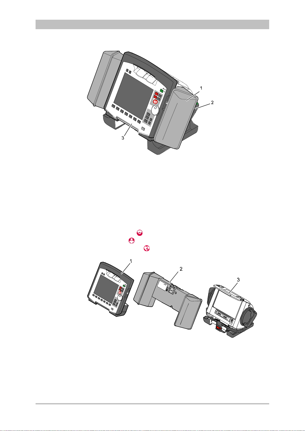
Fig. 3-1 Compact device
1 Accessory bag
2 Shock paddles (2 x)
3 Printer
The corpuls
3
can be tilted vertically up to 30°.
Depending on the mission conditions, the monitor can be adjusted to the
appropriate visual angle.
The system can be divided into the following three modules :
• Monitoring unit
• Patient box
• Defibrillator/Pacer
ENG - Version 2.1 – P/N 04130.2 7
Fig. 3-2 Individual modules
1 Monitoring unit
2 Patient box
3 Defibrillator/Pacer
Page 20
Introduction
Usage options
Radio connection
Note
Infrared
connection
Note
3.2 Device Design
The three modules monitoring unit, patient box and defibrillator/pacer can
operate via an infrared connection or, if separated, via radio connection.
The connection status is shown on the display of the monitoring unit (see Table
4-2, page 36) and the patient box (see Table 4-3, page 39).
Communication between the modules in semi-modular and modular use is
performed by radio up to a distance of 10 m in open terrain.
In the connected mechanically state, the modules communicate via an optical
infrared connection.
If the radio connection is interrupted, the modules have to be connected to each
other mechanically. The corpuls
connection to infrared connection in this case.
The antenna of the radio unit in the patient box is located at the top. In case the
antenna is shadowed, for example by metallic or metallised objects, the
maximal reach of the radio connection may be reduced. This may happen, for
example, when the patient box is placed between the patient’s legs on the
stretcher. If possible, choose a position for the patient box that allows
unimpeded view to the other modules.
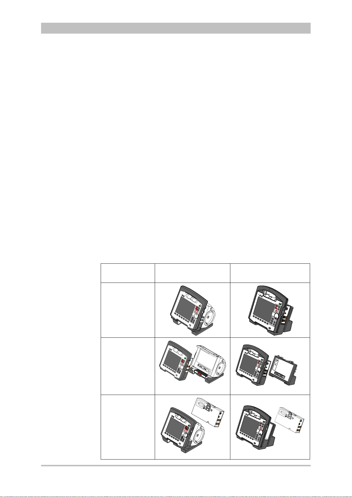
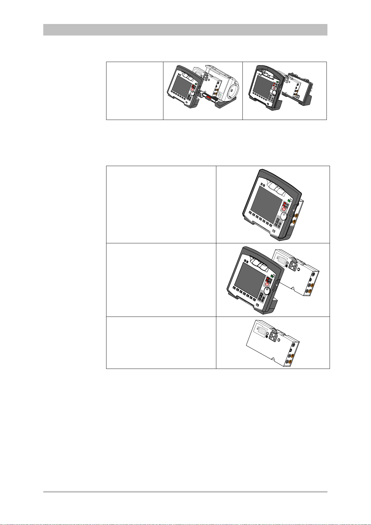
The following combinations are possible:
User Manual corpuls
3
switches automatically from radio
3
Device Design Defibrillator-/pacer unit Defibrillator-/pacer unit
SLIM
1. Compact
device:
All three modules
are connected
mechanically
2. Semi-modular
use:
Monitoring unit
and patient box
are connected,
defibrillator/ pacer
is disconnected.
3. Semi-modular
use:
Monitoring unit
and
defibrillator/pacer
are connected,
patient box is
disconnected.
8 ENG - Version 2.1 – P/N 04130.2
Page 21
User Manual corpuls
3
Introduction
4. Modular use:
Monitoring unit,
patient box and
defibrillator/pacer
are disconnected
mechanically
Fig. 3-3 Usage options of the modular corpuls3
The following combinations are possible when used as a stand-alone patient
monitoring system:
1. Compact monitor:
Monitoring unit and patient box are
connected mechanically
2. Modular monitoring mode:
Monitoring unit and patient box are
disconnected mechanically
3. Patient box:
Patient box in stand-alone use for
temporary initial monitoring
Fig. 3-4 Usage options of the modular corpuls3
as a patient monitoring system
ENG - Version 2.1 – P/N 04130.2 9
Page 22

Introduction
Pairing
Note
Ad-hoc
connection
Prerequisite
Note
Labelling of the
radio modules
2
3.2.1 Pairing (Connection Authorisation)
The modules of the corpuls
means of two procedures:
• Pairing and
• Ad-hoc connection
The corpuls
3
thus provides the option of substituting individual modules of one
compact device for in di vidu al modules of the same t ype f rom another corpuls
It is not possible to connect a monitoring unit to more than one patient box or
one defibrillator/pacer at the same time.
Pairing is a connection authorisation that enables the communication between
wirelessly connected modules.
An ad-hoc connection allows the use of mechanically connected modules
without having to perform a pairing beforehand.
For both procedures the following prerequisites apply:
1. For a pairing, monitoring unit, patient box and defibrillator/pacer have to be
equipped with radio modules of the same type (hardware version).
2. If this is not the case, if the hardware version of the radio modules is
different (1
st
and 2nd generation), those modules can only form an ad-hoc
connection.
3. For both a pairing and for an ad-hoc connection all modules have to be
equipped with an identical sof tware versio n.
As of July 2011 the corpuls3 comes equipped with a second generation radio
module. This new radio module is not compatible with those of the first
generation.
The corpuls
3
modules with the 2nd generation radio module are labelled with a
number symbol. This symbol is attached at the following places:
• Monitoring unit: at the front side, top left,
• Patient box: on top,
• Defibrillator/pacer: at the rear side, on top.
The number symbol also marks the position of the radio module in the modules.
3
can be connected to form a functional unit by
User Manual corpuls
3
3
.
10 ENG - Version 2.1 – P/N 04130.2
Page 23

User Manual corpuls
Note
Starting a Pairing
Starting an ad-
hoc connection
Note
3
Introduction
To star a pairing, proceed as follows:
1. Connect the monitoring unit, the patient box and, if present, the
defibrillator/pacer mechanically.
2. There are the following options:
a) The message Perform pairing? appears:
Confirm the message by pressing the softkey [Start].
b) The message Perform pairing? does not appear:
Select in the main menu "System“► "Start Pairing".
3. The message Pairing successful appears on the screen oft he
monitoring unit. The three modules now are paired. The corpuls
3
is ready
for operation via wireless connection.
To start an ad-hoc connection, proceed as follows:
1. Connect the modules mechanically.
2. Do not confirm the message Perform pairing?
The message Ad-hoc connection [Module], e.g. Ad-hoc
connection P-box or Ad-hoc connection Defib appears on the
screen of the monitoring unit. The corpuls
3
is ready for operation.
The connection status is shown by symbols in the status line in the upper right
corner of the monitoring unit (see Table 4-2 Module connection status, page 36
and Appendix A Symbols, page 272) .
If a new pairing is performed between a monitoring unit and a patient box or
with another compact device, the previously saved wireless connection
authorisation to the patient box or to the defibrillator/pacer is automatically
deleted.
ENG - Version 2.1 – P/N 04130.2 11
Caution
Caution
Warning
When connecting different patient boxes by ad-hoc connection, there can be
inconsistent entries in the data management.
During an ad-hoc connection a wireless connection to other modules is not
possible.
If two modules connected by an ad-hoc connection are separated, a radio
connection to the original patient box and defibrillator/pacer is automatically
re-established.
Page 24
Introduction
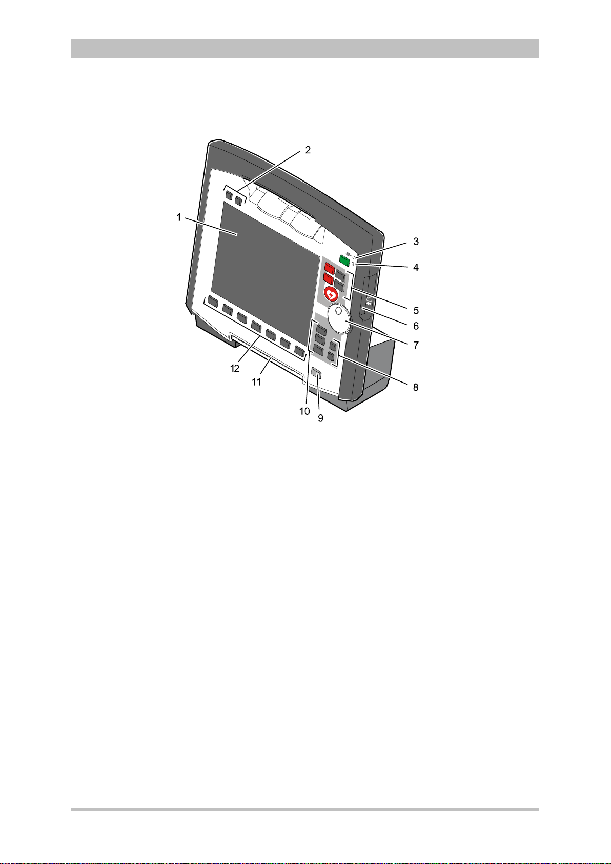
3.2.2 Monitoring Unit
User Manual corpuls
3
Fig. 3-5 Monitoring Unit
1 Display
2 Alarm and event function keys
3 Status LED power supply/charging status
4 On/Off key with operating status LED
5 Defibrillation mode function key s
6 Insurance card reader
7 Jog dial and alarm light
8 Function keys for navigation
9 Print key
10 Operating mode keys
11 Printer
12 Softkeys
The monitoring unit is the central user interface of corpuls
3
. The monitoring
unit comprises the display (item 1), the printer (item 11) and the insurance card
reader (item 6, option) , as wel l th e jog dial (item 7) , the f unc tion keys (items 2, 5,
8 and 9), the operating mode keys (item 10) and the softkeys (item 12).
The jog dial is used to navigate in the main menu, the parameter and curve
context menus and in the display areas on the display.
An alarm light is integrated into the jog dial.
The monitor, pacer and operation browser functions can be selected directly by
pressing the function keys.
Softkey assignment varies according to the selected function. Softkey
assignments are described in the chapters dealing with the respective functions.
12 ENG - Version 2.1 – P/N 04130.2
Page 25
User Manual corpuls
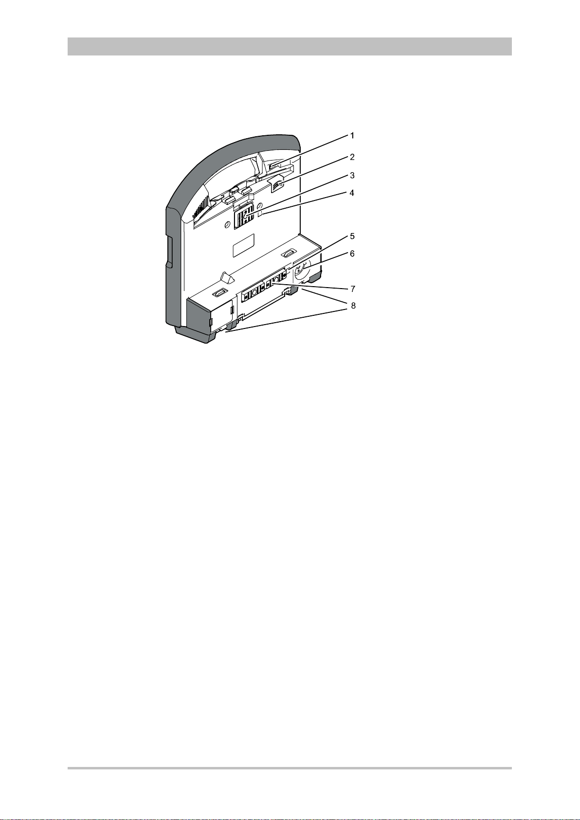
Interfaces
3
Fig. 3-6 shows the interfaces on the monitoring unit
Introduction
Fig. 3-6 Monitoring unit, rear view
1 Cover for LAN interface (option)
2 SIM card slot (slot for SIM card tray)
3 Contact element with patient box
4 Infrared interface with patient box
5 Infrared interface with defibrillator/pacer
6 Charging cable magnetic plug socket
7 Contact element with defibrillator/pacer
8 Fold-out feet
ENG - Version 2.1 – P/N 04130.2 13
Page 26
Introduction
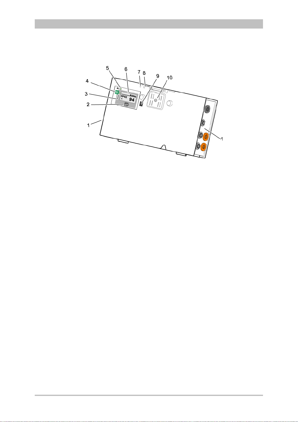
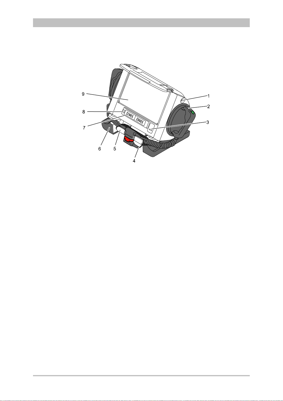
3.2.3 Patient Box and Accessory Bag
Fig. 3-7 Patient Box (illustration may differ)
1 Sensor interfaces
2 Multifunction key
3 Multifunction LED operating status/HR/alarm
4 On/Off key
5 Status LED power supply/charging status
6 Display
7 Microphone
8 Acoustic alarm (pulse signal indicator)
9 Infrared interface with monitoring unit
10 Contact element
The patient box monitors and records the monitoring sensor signals. The
sensors of the various monitoring functions are connected to it.
The patient box can be used as a stand-alone unit (without the monitoring unit)
for patient monitoring. The display (item 6) on the patient box shows the
following:
• The monitoring function values
• Physiological and technical alarms.
• Heart rate is visually represented by an LED (item 3).
User Manual corpuls
3
14 ENG - Version 2.1 – P/N 04130.2
Page 27
User Manual corpuls
Rain
bow
Right-hand side
Left-hand side
3
Patient Box Interfaces
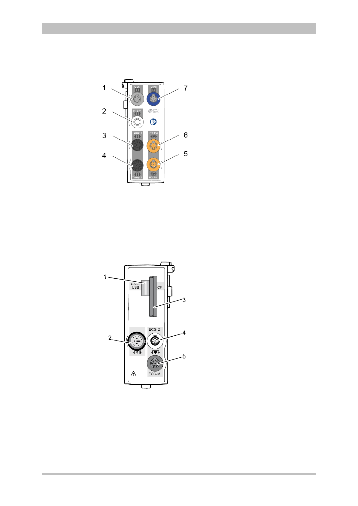
Fig. 3-8 Patient Box Interfaces, right hand side, ports for:
1 CO2: sensor for capnometry
2 NIBP: sensor for non-invasive blood pressure monitoring
3 Temp-1: temperature sensor
4 Temp-2: temperature sensor
5 P1 P2: sensor for invasive blood pressure monitoring (channels 1 and 2)
6 P3 P4: sensor for invasive blood pressure monitoring (channels 3 and 4)
7 CPR: CPR feedback sensor
Introduction
ENG - Version 2.1 – P/N 04130.2 15
Fig. 3-9 Patient Box Interfaces, left hand side, ports for:
1 USB interface (devices up to 09/2010)
2 Rainbow®: interface for oximetry sensor
3 CF: slot for CompactFlash® card for data back-up
4 ECG-D: complementary ECG diagnostic cable
5 ECG-M: ECG monitoring cable
Page 28
Introduction
Caution
At the moment, connecting USB devices or –cables to the USB slot is not
allowed.
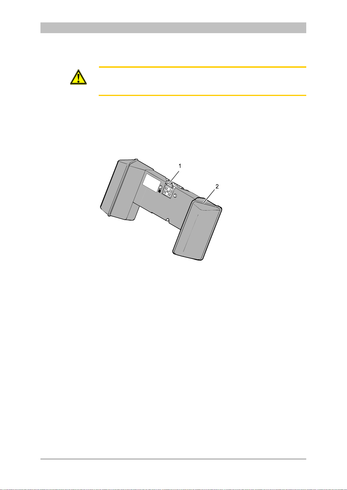
Accessory Bag
An accessory bag is available for the patient box (P/N 04221.1).
The accessory bag is used to store the preconnected cables as well as the
sensors and ECG electrodes, so that they are quickly accessible during use.
User Manual corpuls
3
Fig. 3-10 Patient Box with Accessory Bag
1 Patient box
2 Accessory bag
Chapter 4.5 Accessory Bag, p. 56 contains information on installing and packing
the accessory bag.
16 ENG - Version 2.1 – P/N 04130.2
Page 29
User Manual corpuls
3
3.2.4 Defibrillator/Pacer
Introduction
Fig. 3-11 Defibrillator/Pacer
1 Equipotential bonding pin with insu lat ing cap
2 Shock paddle
3 On/Off key
4 Therapy master cable with plug
5 Cable socket with test contact
6 Stand and storage compartments
7 Contact element with monitoring unit
8 Infrared interface with monitoring unit
9 Compartment for corPatch electrodes
The therapy electrodes have to be connected to the therapy master cable
(item 4). The therapy master cable can be wound around the socket (item 5).
The plug can be lodged in the socket.
Equipotential bonding can be performed during clinical use with the
equipotential bonding pin (item 1). For this, the insulating cap has to be
removed.
The shock paddle marked with the green label APEX must be positioned in the
right-hand shock paddle holder to ensure that the twistproof plug connector on
the therapy master cable is correctly aligned. For guidance, identical labels for
the APEX and STERNUM shock paddle are located on the side of the
defibrillator/pacer. The plug can be lodged in the socket.
The stand (item 6) additionally serves as a storage compartment for electrode
gel and razors, etc.
The angle of the defibrillator/pacer can be tilted vertically (30°) to achieve an
optimal view of the screen during use.
ENG - Version 2.1 – P/N 04130.2 17
Page 30
Introduction
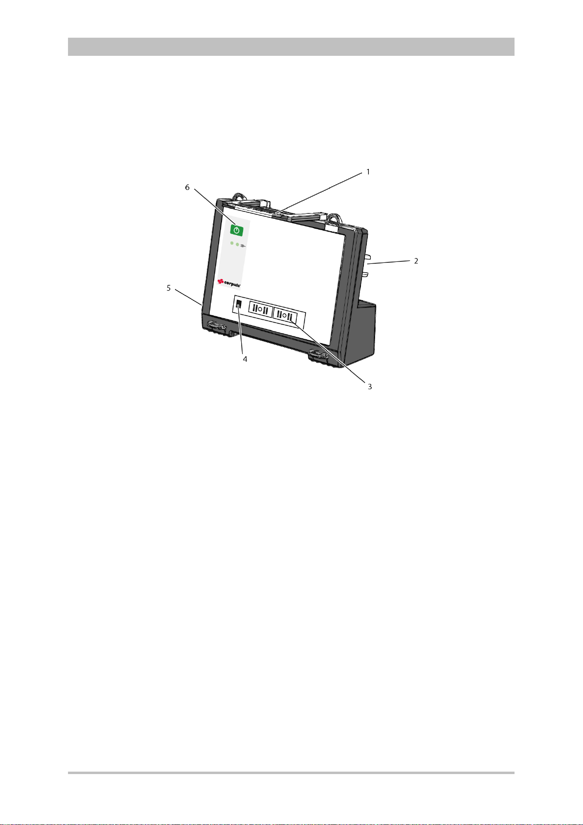
3.2.5 Defibrillator/P acer SLIM
The defibrillator/pacer SLIM differs from the previous defibrillator/pacer unit only
in terms of form and weight.
The basic functions are identical.
User Manual corpuls
3
Fig. 3-12 Defibrillator/Schrittmacher Slim
1 Carrying handle and lock
2 Therapy socket
3 Contact element with monitoring unit
4 Infrared interface with monitoring unit
5 Equipotential bonding pin with insu lat ing cov er
6 On/Off key
The therapy electrodes have to be connected to the therapy socket (item 2).
Equipotential bonding can be performed during clinical use with the
equipotential bonding pin (item 5). For this, the insulating cover has to be
removed.
18 ENG - Version 2.1 – P/N 04130.2
Page 31
User Manual corpuls
Table
3
Introduction
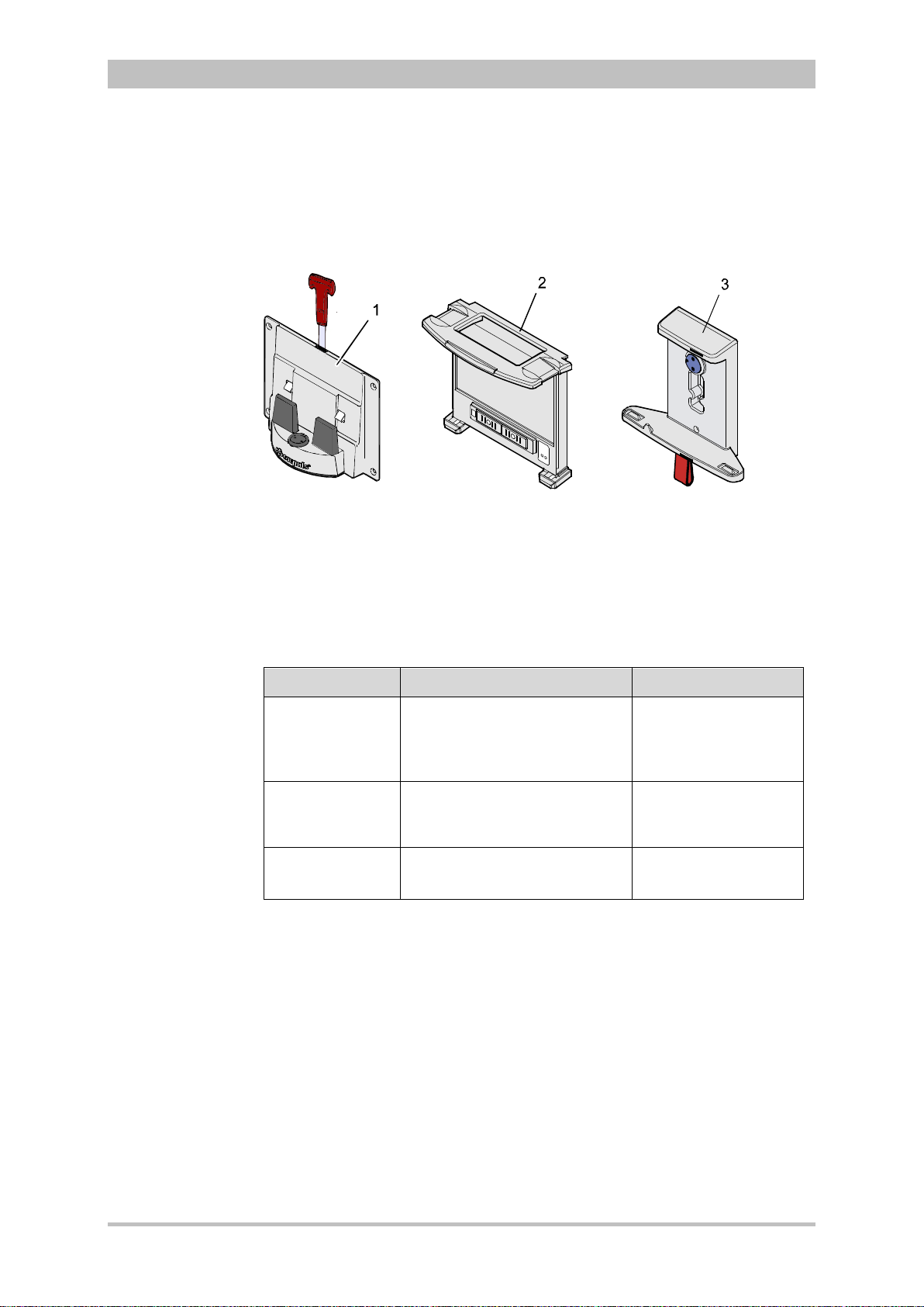
3.2.6 Brackets
Various brackets, with and without power supply, are available for the device in
compact, semi-modular or modular use.
Fig. 3-13 Brackets
1 Defibrillator/compact device bracket
2 Monitoring unit bracket
3 Patient box bracket
Chapter 4.6 Inserting the D ev ic e into the Brac k ets, p. 60 contains information
on inserting the modules into the brackets.
Bracket Use Power
Bracket for
defibrillator/
compact device
Defibrillator/pacer and
modules connected
mechanically to the
− 12 V DC
− No power supply
defibrillator/pacer
Bracket for
monitoring unit
Monitoring unit and patient box
connected mechanicall y to the
− 12 V DC
− No power supply
monitoring unit
Bracket for
patient box
Patient box
− 12 V DC
− No power supply
3-1 Brackets and power supply options
The charging brackets can also be connected to voltages other than 12 V DC
using DC/DC or AC/DC converters.
ENG - Version 2.1 – P/N 04130.2 19
Page 32

Introduction
ECG
Diagnostic ECG
Oximetry
Capnometry
Temperature
CPR feedback
3.3 Description of the Monitoring, Diagnostic and
Therapeutic Functions
3.3.1 Monitoring and Diagnostic Functions
The corpuls
• ECG
• Diagnostic ECG
• CPR feedback
Optional:
• oximetry (SpO
• Capnometry (CO
• Temperature (Temp)
• Non-invasive blood pressure monitoring (NIBP)
• Invasive blood pressure monitoring (IBP)
With the 4-pole ECG monitoring cable, the bipolar extremity leads according to
Einthoven (I, II, III) and the unipolar extremity leads according to Goldberger
(aVR, aVL, aVF) can be derived and displayed on the monitor.
By combining the 4-pole ECG monitoring cable with the complementary 6-pole
ECG diagnostic cable (chest wall leads according to Wilson (C1-C6)), 12
channels can be displayed simultaneously. This enables a comprehensive ECG
diagnosis which can be supported by the ECG measurement HES
an optional ECG analysis software.
During resuscitation, the CPR feedback option monitors the current
compression rate and -depth of the thorax compressions by means of the
corPatch CPR sensor. Speech- and text messages signal to the user whether
the quality of the thorax compressions is sufficient or can to be optimised.
Besides the peripheral pulse rate (PP), oximetry measures the perf us ion index
(PI), the arterial oxygen saturation (SpO
methemoglobin (SpMet
level of carboxyhemogolobin (SpCO
hemoglobin (SpHb) in g/dl or mm ol/l. Up to six param et er fields w ith digit al
measuring values can be configured for display. A curve field can display the
oximetry plethysmogram.
The capnometer, which works according to the mainstream method, measures
the CO
concentration, measured in mmHg or kPa, can be displayed on the screen as a
capnogram. The corpuls
intubated patients. The patient’s respiratory rate is measured as an additional
parameter.
Up to two temperature values can be measured by means of temperature
sensors and displayed as numerical values: body core temperature rectally
and/or oesophageally and surface temperature.
3
has the following monitoring and diagnostic functions:
®,
SpCO
2,
2
®
concentration in the patient’s expiratory breath in real time. The CO2
2
SpHb, SpMet®)
)
) and, depending on the used oximetry sensor, the
3
allows use of capnometry in intubated and non-
User Manual corpuls
) in percentage, the level of
2
®)
in percentage or the level of total
®
Light and
3
20 ENG - Version 2.1 – P/N 04130.2
Page 33
User Manual corpuls
U [V]
t [ms]
Non-invasive
blood pressure
(NIBP)
Invasive blood
pressure (IBP)
3
Introduction
The non-invasive blood pressure function (NIBP) allows blood pressure
monitoring on one extremity. A selection of operating modes for adults, children
and infants is available.
The invasive blood pressure function (IBP) allows the invasive measurement of
various different pressures as part of intensive medical care of the patient.
These include, among others, arterial pressure, central venous pressure and
intracranial pressure, etc .
Two interfaces are available which can be assigned as single channels or as
double channels, respectively. Consequently, up to four different invasive
pressure measurements can be performed simultaneously. The recorded
pressure values can be displayed on the screen either as numerical parameters
and/or as a curve.
3.3.2 Therapeutic Functions
corpuls
3
provides the following therapeutic functions:
• defibrillation
• cardioversion
• pacing
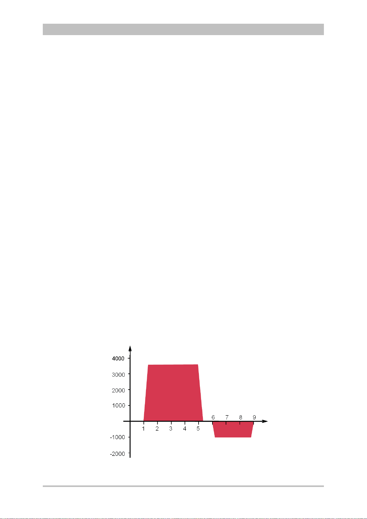
Defibrillation and Cardioversion
The defibrillator which operates with the corpuls3-specific biphasic pulse has
two operating modes:
• automatic external defibrillation (AED mode)
• manual defibrillation and cardioversion (manual mode)
Fig. 3-14 Biphasic defibrillation pulse (qualitative representation)
ENG - Version 2.1 – P/N 04130.2 21
Page 34

Introduction
A cardioversion may lead to fibrillation or asystole. When performing a
status.
Energy selection
FIX
DEMAND
OVERDRIVE
function
Defibrillation
electrodes
In AED mode, the user is assisted by an automated ECG analysis, verbal
instructions (configurable) and a metronome (configurable). The defibrillation
pulse is triggered by the user.
The AED mode algorithm is governed by the current recommendations of the
European Resuscitation Council of 2010 (ERC, see www.erc.edu).
In manual defibrillation mode, the user has full freedom of action and decisionmaking. The metronome (configurable) is available in this mode as well.
Defibrillation can be performed with corpuls
shock paddles and with disposable adhesive electrodes, so-called corPatch
electrodes.
There are three different options for selecting energy in manual mode:
• Softkeys
The softkeys allow a choice of predefined energy settings (e.g. 50 J,
100 J, 150 J, 180 J, 200 J).
• Jog dial
The jog dial allows selection of 2 J, 3 J, 4 J and 5 J and subsequently in
5 J-increments up to a maximum energy of 200 J.
• Shock paddles
By short-circuiting the shock paddles, the energy can be selected by
pressing the release buttons. This function allows the same energy
selection as with the jog dial.
User Manual corpuls
3
using plate electrodes, so-called
3
cardioversion, mind the following:
Warning
• The ECG has to be stable with a heart rate of at least 60/min.
• The synchronisation status has to remain constantly on SYNC.
• The QRS marks (triangles) have to mark each QRS complex.
• The shock release has to be effected according to valid guidelines.
• If the shock release does not take place one second after pressing
the buttons at the shock paddles or the Shock key at the monitoring
unit, the shock will be released independent of the synchronisation
Pacing
By electrical stimulation of the heart muscle, the external pacer of corpuls3
can supplement, positively influence or completely take over its function. The
pacer emits pacing pulses to the patient’s heart muscle through the corPatch
electrodes attached to the chest/back.
With the pacer function, the FIX and DEMAND operating modes are available
as well as the function OVERDRIVE.
In the FIX operating mode, the heart muscle is stimulated regardless of the
patient’s own heart rate.
The pacer only stimulates in DEMAND mode when the patient’s own heart rate
falls below the pre-set pacing frequency. The automatic R-wave recognition
prevents pacing during the vulnerable phase of the heart.
The OVERDRIVE functio n allo ws manual reduction of a patient ’s hig h hear t rat e.
The maximum pacing frequency is f ≤ 300/min.
22 ENG - Version 2.1 – P/N 04130.2
Page 35

User Manual corpuls
Table
Frequency and
intensity
Physiological and
technical alarms
Alarm signals at
monitoring unit
d patient box
Note
Priorities
Active and non-
Note
3
Introduction
Minimum Maximum Increment
active alarms
an
Pacing frequency
30/min 150/min 5/min
FIX operating mode
Pacing frequency
30/min 150/min 5/min
DEMAND operating mode
Pacing frequency
30/min 300/min 1/min
OVERDRIVE function
Intensity 10 mA 150 mA 5 mA
3-2 Frequency and intensity
3.4 Al ar m ma nagement
The alarm management of the corpuls
priorities, into physiological and technical alarms as well as into active and nonactive alarms.
High-priority alarms warn the user of immediate lethal or irreversible injuries of
the patient or of malfunctions in the device. High-priority alarms cannot be
interrupted by medium-priority- or lo w-priority alarms.
Medium-priority alarms alarms warn the user of immediate reversible injuries of
the patient or of minor malfunctions in the device. Medium-priority alarms
cannot be interrupted by low-priority alarms. High-priority alarms always take
precedence over medium-priority- or low-priority alarms.
Low-priority alarms warn the user of minor injuries of the patient that may occur
later or of minor limitations to the functionality of the device. High- and mediumpriority alarms always take precedence over low-priority alarm s.
The physiological alarms are displayed if measured values exceed or fall below
the pre-set limit values of the alarm. Technical alarms are displayed, if there is a
malfunction in the device. If the corpuls
mode, the physiological alarms are not signalled.
The physiological and technical alarms and the necessary troubleshooting
measures are listed in chapter 10 Procedure in Case of Malfunctions, page 233.
Alarms are active, if the conditions that trigger the alarm are present. Alarms
are non-active, if the conditions that trigger the alarm have been remedied, but
the alarms are still listed in the alarm history for information.
3
The corpuls
issues visual alarm signals at the monitoring unit and at the
patient box. If there is no connection between the monitoring unit and the
patient box, acoustic alarm signals are issued at both modules. If there is a
connection, acoustic alarm s are issued on l y at the monitoring unit.
No alarm signals are issued at the defibrillator/pacer. Alarms of the
defibrillator/pacer are signalled at the monitoring unit.
During modular operation of the corpuls
delay of up to 30 seconds.
3
classifies all alarms into three different
3
is in AED or manual defibrillation
3
, alarms may be signalled with a
ENG - Version 2.1 – P/N 04130.2 23
Page 36

Introduction
Note
Note
Sorting of alarm
ory
3.4.1 Alarm Signals at the Monitoring unit
Physiological and technical alarms are signalled at the monitoring unit via the
status line, the vital parameter field, the jog dial and by acoustic signals. The
positions of the operation- and display elements are described in chapter 4.1
Operating and Display Elements, page 31.
Alarm signal in the status line
Fig. 3-15 Alarm message in the status line
User Manual corpuls
3
hist
− The bell symbol
indicates an alarm.
− The number in brackets indicates the number of active alarms
(here 4 alarms)
− The number of exclamation marks indicates the priority of the alarm
(!!! – high; !!HIGH – medium; ! – low)
− The colour of the status line indicates the priority of the alarm
(red – high; yellow – medium; blue – low)
− The alarm is displayed as a text message together with the pre-set
limit value.
Pressing the Alarm key once opens the alarm history which lists the last 8
alarms. The individual alarms can be confirmed by pressing the Alarm key
again. In this case, the most recent alarm message is deleted from the status
line of the monitoring unit and from the display of the patient box.
In the alarm history all active and non-active alarms are displayed that have not
yet been confirmed; with the alarms being sorted top-down from active (top) to
non-active (bottom). Within the active and non-active alarms, the alarms are
sorted by priority and then in descending order by the time of their occurrence.
The alarm history can contain up to 256 alarms. Preferably these should be
confirmed as soon as possible. If more than 256 un-confirmed alarms
accumulate, the oldest alarm is overwritten.
Certain technical alarms are displayed in red type. These alarms cannot be
deleted from the status line and alarm history.
Alarm signal in parameter field displayed in inverted colours:
24 ENG - Version 2.1 – P/N 04130.2
Fig. 3-16 Inverted parameter field
− This display appears only for physiological alarms.
− The parameter field can only be displayed in inverted colours when the
display of this parameter field is configured.
− The parameter field remains in inverted colours for as long as the
measured value falls below or exceeds the pre-set limit value or until the
alarm for this measured value is disabled.
This applies regardless of whether the alarm message in the status line
has been confirmed by pressing the Alarm key or not.
Page 37

User Manual corpuls
Configuration of
alarms
Defibrillation
mode
Alarm
suspension
Situation after
switching on
3
Introduction
Alarm signal via the jog dial:
Fig. 3-17 Jog dial
1 Not illuminated
2 Illuminated to indicate an alarm
− The alarm with the currently highest priority is indicated by the colour blue,
yellow or red (in older devices only red) as well as by the flashing speed
of the jog dial.
− The priority of the alarm determines the flashing speed. The flashing speed
increases with the priority.
The acoustic alarm sounds:
− The alarm with the highest priority is signalled acoustically.
− The type of sound helps the user to differentiate between low-, medium-
and high-priority alarms.
If the Alarm key is pressed for more than 3 s, physiological alarms can be
suspended briefly or, depending on the configuration set by the operator, also
permanently. Prerequisite is that this has been configured accordingly in the
settings (see chapter 7.4.5 Alarm Configuration (Persons Responsible for the
Device) , page 166).
Only technical alarms are displayed in defibrillation mode. Physiological alarm
limits are not monitored.
No physiological alarm events are saved in defibrillation mode.
ENG - Version 2.1 – P/N 04130.2 25
WARNING
WARNING
The patient must not be left unattended when defibrillation mode is selected.
Manual and automatic configuration as well as all further settings (saving,
volume, etc.) with reference to the alarm function of the monitoring unit can be
found in chapter 7.3 Alarm Configuration, page 155.
After switching on, the settings entered by the person responsible for the device
apply. Differing alarm settings are only saved permanently if the user has the
appropriate authorisation.
Night vision goggle (NVG/NVIS)-compatible monitoring units differ from the
above description as follow s:
• The illumination of the jog dial for signalling an alarm is not red but
cyan (light-blue).
• The maximum brightness of the illumination of the jog dial is only 5%
of the regular configuration.
• The signalling of an alarm via the jog dial is not visible in daylight and
difficult to see in the twilight.
• The representation of colours on the screen differs. Due to this, signal
colours may not be recognised as such.
Page 38

Introduction
Situation after
switching on
Configuration of
alarms
3.4.2 Alarm Signals at the Patient box
Physiological and technical alarms are signalled on the patient box in various
ways:
Alarm message on the patient box display:
Fig. 3-18 Alarm message on the patient box display
− The bell symbol indicates an alarm.
− The number in brackets indicates the number of active alarms
(here 1 alarm)
− The number of exclamation marks indicates the priority of the alarm
(!!! – high; !!HIGH – medium; ! – low)
− The alarm is displayed as a text message together with the pre-set
limit value and the timestamp of the alarm.
The individual alarm s c an b e c onf irmed by pressing the Multifunction ke y once.
If a radio connection to the monitoring unit exists, the most recent alarm
message is deleted from the status line and alarm history of the monitoring unit
and from the display of the patient box.
User Manual corpuls
3
• The acoustic alarm sounds:
− Acoustic alarms are only signalled, if no radio connection to the monitoring
unit exists.
If a connection to the monitoring unit exists, the acoustic alarm only
sounds on the monitoring unit; the alarm on the patient box is suspended.
The alarm limits can be modified on the monitoring unit. Manual and automatic
configuration in addition to further sett ings perta in ing to the alarm function can
be found in chapter 7.3 Alarm Configuration, page 155.
After switching on, at first the settings entered by the person responsible for the
device apply. Differing alarm settings are only saved permanently if the user
has the appropriate authorisation.
26 ENG - Version 2.1 – P/N 04130.2
Page 39

User Manual corpuls
Influence of the
modular
structure
Identical lithium-
ion batteries
Remaining
running time
display
Empty or faulty
batteries
Note
Note
Note
3
Introduction
3.5 Energy Management
Energy management is of paramount importance owing to the modular structure
of the corpuls
The corpuls
on 12 V DC power supply or via a separate charger (only 230 V AC).
3.5.1 Battery Operation
The three modules of corpuls
batteries are identical and have an integrated microchip which records the
history of use.
Each of these batteries can be replaced manually and without use of tools.
Exchanging the batteries for one another within the corpuls
Information on replacing the batteries can be found in chapter 9.6 Changing the
Battery, p. 218.
When the modules of the corpuls
device or semi-modular use), the energy is drawn from the battery with the
currently highest state of charge. If the state of char ge i s ident ic al in all batt er ies,
the corpuls
If only a low level of charge remains in the battery of one module, it is possible
to access the energy reserves of the other batteries by connecting this module
to one or both other modules.
If the charging status of a battery is less than 20 % of the total charge of the
module, an alarm message for the respective module is triggered.
To guarantee a sufficient charge, the corpuls
charging bracket or connected to the external charger.
One battery with adequate charge is sufficient to operate the device reliably as
compact device.
Energy exchange or mutual charging between the batteries does not occur.
The corpuls
directly on 12 V DC or via a separate charger (230 V AC).
The corpuls
To be able to offer the user the maximum possible safety, the corpuls
calculates the remaining running time and indicates this in minutes. In
calculating the remaining running time, the device takes the current energy
consumption into account.
The remaining operating time is displayed in the status line of the monitoring
unit (Fig. 3-19).
3
.
3
and the individual modules can be operated on batter y alone or
3
each have their own lithium-ion battery. The
3
is also possible.
3
are connected mechanically (compact
3
accesses all available batteries equally.
3
has to be inserted into the
3
as well as the individual modules can be operated on battery,
3
is only intended for use with all three batteries inserted.
3
ENG - Version 2.1 – P/N 04130.2 27
Fig. 3-19 Remaining running time of the corpuls
status
1 Battery symbol and remaining running time in minutes
3
in the current operating
Page 40

Introduction
1
Charging time
Operating time
Battery charging
Battery
maintenance
Note
Note
In case of modular use of the patient box, the remaining running time of the
patient box, taking into account the current energy consumption, is displayed
(Fig. 3-20).
Fig. 3-20 Remaining running time of the patient box
1 Battery symbol and remaining running time in minutes
Alternatively, the charging status of the batteries in percent can be viewed in the
system info. In the main menu, select "System" ► "Info".
Since each module has a charging manager, it can be charged individually and
independently from the other modules.
Furthermore, in compact or semi-modular use, the system can also be charged
by only one magnetic contact. In this case, the charging time is independent of
whether only one or several modules are simultaneously charged by an external
power supply.
3
During charging, the corpuls
system can be operated.
Special maintenance of the batteries is not required. Nevertheless, charging
and/or operating under extreme temperatures should be avoided as far as
possible. This and extreme temperature fluctuations limit the service life of
lithium-ion batteries. It is therefore recommended to charge the batteries within
a temperature range from 12°C to 40°C.
Periodic replacement of the batteries after 3 years is recommended.
• Compact device: approx. 7-10 hours
• Patient box: approx. 4-6 hours
• Monitoring unit: approx. 4 hours (at 70% background
illumination)
• Defibrillator/Pacer: up to 200 shocks at 200 J
• From 0 to 80 %: approx. 1 hour
• From 0 to 90 %: approx. 1.5 hours
• From 0 to 100 %: approx. 2 hours
In case of a system crash of one or all modules the batteries do not have tob e
removed. By keeping the On/Off key depressed for a duration of 8 sec. the
individual modules can be forcibly shut down (see also chapter 4.2.2 Switching
Off, p. 44).
The batteries have an internal protect ion wh ich cou ld dela y or interrupt the
charging process at ambient temperatures of higher than 50°C.
User Manual corpuls
3
28 ENG - Version 2.1 – P/N 04130.2
Page 41
User Manual corpuls
Operation with
V DC
Use of a mains
charger
Magnetic contact
field
Charging
brackets
State of charge
display
Charging during
operation
12
3
Introduction
3.5.2 Mains Operation
The compact device and each individual module can be operated directly with
12 V DC.
In combination with a multi-range mains charger, the compact device and the
individual modules can also be connected to and operated with voltage sources
of 100 V to 250 V AC. Operation with the mains charger on a source of
alternating current functions regardless of whether no batteries, empty batteries
or faulty batteries are used.
The current charging status of the batteries is displayed on the status line of the
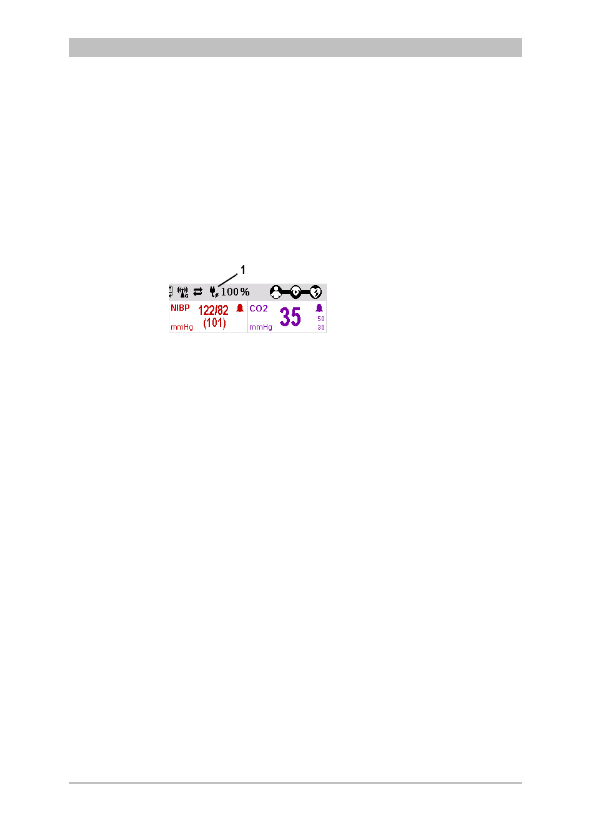
monitoring unit (Fig. 3-21).
Fig. 3-21 Display of the current state of charge of the batteries on mains
operation
1 Symbol for mains connection and state of charge of the batteries in
percent
The voltage can also be supplied by the three available charging brackets:
• compact device bracket 12 V DC (P/N 04400)
• monitoring unit wall mounting bracket 12 V DC (P/N 04401)
• patient box bracket 12 V DC (P/N 04402)
These brackets can also be connected to voltages sources other than 12 V DC
via DC/DC or AC/DC converters.
If batteries are present in the device, they will be charged during use.
Each of the three modules has its own magnetic contact field for power supply.
The flow of energy only begins when the corresponding magnetic mating
component (magnetic clip or bracket supplied with voltage) is applied in the
correct position (observe groove). The magnetic clip releases itself
automatically if the pulling force becomes excessive. Manual release is not
necessary.
The connection (item 1, Fig. 3-22) on the defibrillator/pacer is used for power
supply of
• the entire device in compact use,
• the defibrillator/pacer and the monitoring unit in semi-modular use or
• the defibrillator/pacer in modular use.
ENG - Version 2.1 – P/N 04130.2 29
Page 42

Introduction
1
2
1
2
Fig. 3-22 Compact device, power supply (illustration may differ)
1 Power supply connection
2 Magnetic clip
User Manual corpuls
3
Fig. 3-23 Monitoring unit, power supply
1 Power supply connection
2 Magnetic clip
Fig. 3-24 Patient box, power supply (illustration may differ)
30 ENG - Version 2.1 – P/N 04130.2
1 Power supply connection
2 Magnetic clip
Page 43
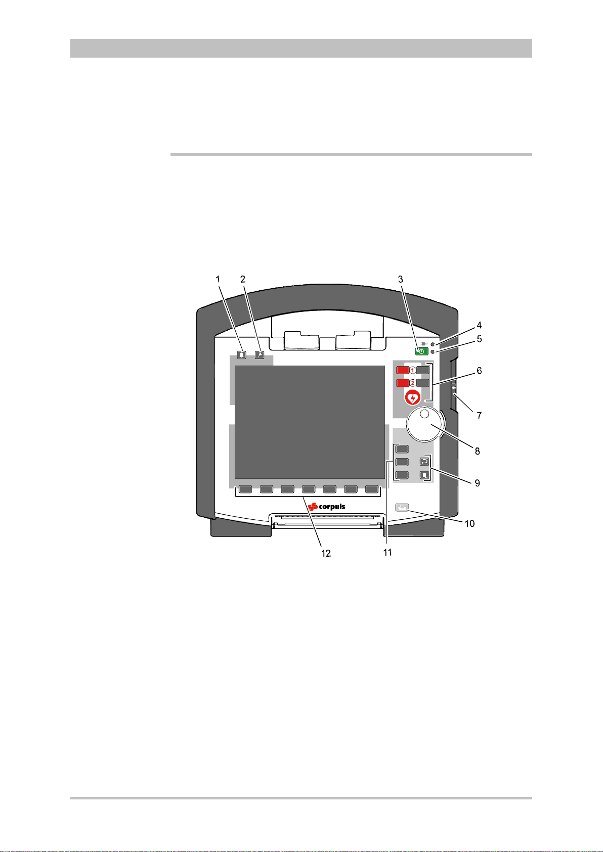
User Manual corpuls
AED
Analyse
Schock
Energi
e
Lade
n
AED
A
nalyse
Charge
Manual
M
onito
r
Pa
c
er
Browser
3
General Operating Instructions
4 General Operating Instructions
4.1 Operating and Display Elements
4.1.1 Operating Elements and LEDs on the Monitoring Unit
Fig. 4-1 Monitoring unit, operating elements and LEDs
1 Alarm key
2 Event key
3 On/Off key
4 Power supply/state of charge status LED
5 Operating status LED
6 Defibrillation mode function key s
7 Insurance card reader (optional)
8 Jog dial and alarm light
9 Function keys for navigation
10 Print key
11 Operating mode keys
12 Softkeys
ENG - Version 2.1 – P/N 04130.2 31
Page 44

General Operating Instructions
LED
green
-
orange
LED operating status (item 5)
green
AED
The red
defibrillation“
The
this operating mode is immediately available.
Ana
lys
e
The red
Manuell
Manual
Energy
The grey
defibrillation”.
The
This operating mode is immediately
LadenCharge
Charge
The grey
Shock
The
mode. It
Table
Status LEDs
Function keys,
defibrillation mode
On/Off key
Note
The following modules are switched on or off by pressing the On/Off key on the
monitoring unit:
• all modules during use as a compact device;
• the monitoring unit and all the modules connected mechanically to the
monitoring unit during semi-modular use;
During modular use only the monitoring unit is switched on with the On/Off key,
but all modules are switched off with it. Chapter 4.2 Switching On and Off,
page 43 contains further information on switching on and off.
The status LEDs of the monitoring unit indicate the power supply or the state of
charge of the batteries in addition to the operating status of the device:
User Manual corpuls
3
power supply/
state of charge (item 4)
- battery is fully charged
device is connected to the mains
- battery is being charged
- device is switched on
When the device is equipped with night visi on gog gl e (NVG/NVIS)-compatibility,
the LED power supply/charging status and the multifunctional LED glow yellow
instead of orange.
The defibrillation and cardioversion functions are called up by pressing the
defibrillation mode function keys (item 6) (see also chapter 5 Operation –
Therapy, p. 63).
AED key selects the operating mode “automated external
corpuls
.
3
can be switched on by pressing the AED ke y. So
Analyse key starts ECG analysis.
Manual key selects the operating mode “manual
or
corpuls
3
can be switched on by pressing the Manual key.
available in this case.
or
or
4-1 Keyboard layout defibrillation keys (modifications possible)
32 ENG - Version 2.1 – P/N 04130.2
Charge key initiates the charging process.
Shock key triggers a defibrillation shock in AED- or manual
is positioned centered, as it is valid for both modes.
Page 45

User Manual corpuls
Monitor
The
Pacer
The
Browser
The
held down for more than 3
The
1.
2.
Back and Home
function keys
Operating mode
keys
Jog dial
Print key
Note
Note
3
General Operating Instructions
With the jog dial, it is possible to:
• navigate on the display;
• open a parameter context menu or curve context menu pertaining to a
parameter or curve and adjust settings (see chapter 4.3.2 Parameter
Context Menu and Curve Context Menu, p. 47);
• open the main menu of the device and adjust settings (see chapter 4.3.3
Main Menu, p. 49);
• adjust numerical values in defibrillation mode and pacer mode;
• adjust settings in the configuration dialogue (see chapter 4.3.4
Configuration Dialogue, p. 50).
The different operating modes are selected by pressing the following keys (Fig.
4-1, item 11):
Monitor key selects the monitoring functions (monitoring mode)
Pacer key switche s the device to pacer mode
Browser key starts printing of the log. If the Browser k ey is
seconds, the operation browser opens.
The function keys Back and Home (Fig. 4-1, item 9) are used to control the
device:
Back key returns to the next menu level up or undoes the last selection.
The Home key switches to the basic status of the respective mode and
leaves menus completely by skipping several levels.
By pressing the Home key, the keyboard lock engaged:
a) Press the Home key for approx. 2 sec.
The confirmation prompt "Lock keyboard?" appears.
b) Hold the Home key down and press the left softkey [Lock].
The message text "Keyboard locked" appears and the keyboard is
locked.
c) The keyboard is unlocked in the same manner.
If a key is pressed while keyboard lock is active, the message text "Keyboard
locked -> press and hold HOME to unlock" appears. Deactivate
keyboard lock immediately to avoid delaying necessary operating steps on the
device.
The keyboard lock is not valid for the red or green button at the shock paddles.
A discharge of energy via shock paddles is possible despite an activated
keyboard lock.
Pressing the Print key (Fig. 4-1, item 10) starts the real-time printout of the
curves. Pressing the Print key again interrupts every running print job (log, DECG, real-time printing).
ENG - Version 2.1 – P/N 04130.2 33
Page 46

General Operating Instructions
Softkeys
Alarm key
Event key
Note
Note
Note
The time span after which the printer stops automatically can be pre-set in the
printer configuration. For more information see chapter 7.1.3 Printer settings,
p. 143.
The softkeys (Fig. 4-1, item 12) are assigned different functions, depending on
the current operating mode or selected dialogue. The current function is
displayed in the softkey line.
By pressing the Alarm key (Fig. 4-1, item 1), the alarm history of all
physiological and techn ical alarms is called up. All the alarms which have
occurred appear in this list with their time of occurrence.
1. Press the Alarm key to retrieve the alarm history.
2. Press the Alarm key to confirm the alarm.
3. Repeat step 2 until all alarms have been confirmed.
Severe technical alarms reported by the alarm system cannot be deleted from
the alarm history and are marked in red type.
Physiological alarms can be suspended for a selected time span (up to 120 sec
or permanently; see chapter 7.4.5 Alarm Configuration (Persons Responsible
for the Device), page 166) by pressing the Alarm key for approx. 3 sec.
Technical alarms cannot be suspended.
For the alarm suspension, a maximum period of 60 seconds is recommended
(see also chapter 7.4.5 Alarm Configuration (Persons Responsible for the
Device), p. 166).
Pressing the Event key (Fig. 4-1, item 2) records a time stamp which marks the
current ECG data and vital parameter values. Based on this marking, this data
can subsequently be located in the data memory, viewed and assessed.
If voice recording is enabled, pressing the Event key also stores a 15 second
recording of the surrounding noises (5 sec. before and 10 sec. after pressing
the key).
Pressing the Event key appears as a “Event recorded” in the log.
If the lead DE should be represented in the monitoring mode, select this via the
curve context menu (see chapter 4.3.2 Parameter Context Menu and Curve
Context Menu, page 47).
User Manual corpuls
3
34 ENG - Version 2.1 – P/N 04130.2
Page 47

User Manual corpuls
Status line
Note
3
General Operating Instructions
4.1.2 Basic Structure of the Display Pages on the Monitoring Unit
The display has the following structure:
Fig. 4-2 Monitoring unit, example of basic structure of the display pages
1 Status line
2 Parameter area
3 Curve and display area
4 Message line
5 Softkey line
The colours of the parameters and curves in the illustrations of this user manual
may differ from the actual display.
The following data are displayed in the status line (item 1):
• Physiological and technical alarms
• Patient’s name (editable)
• Time and deployment time alternating every 5 seconds
• Symbols for telemetry-functions
• State of charge of the batteries on mains operation
• Remaining running time of the device on battery operation
• Connection status of the modules
Connection status Meaning
ENG - Version 2.1 – P/N 04130.2 35
All three components are connected mechanically
and communicate visually via an infrared
interface.
Page 48
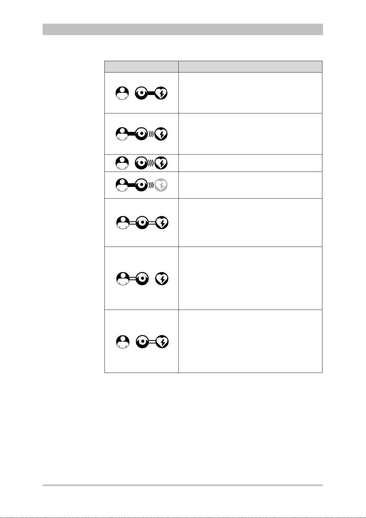
General Operating Instructions
(((
(((
x
x
Table
Parameter area
Curve and
y area
Note
Connection status Meaning
The monitoring unit and defibrillator are connected
mechanically and communicate visually via an
infrared interface.
The patient box is disconnected mechanically, but
there is a radio connection with the patient box.
The monitoring unit and patient box are connected
mechanically and communicate visually via an
infrared interface.
The defibrillator is disconnected mechanically, but
there is a radio connection with the defibri llator .
All components have a radio connection.
User Manual corpuls
3
The defibrillator was not switched on together with
the corpuls
currently.
All three components are connected mechanically
and communicate via the infrared optical
interface.
A wireless connection is not possible, because all
three components are connec ted with an ad-hocconnection.
Monitoring unit and patient box are connected
mechanically and communicate via the infrared
optical interface.
A wireless connection is not possible, because
both components are connected with an ad-hocconnection.
The defibrillator is disconnected; there is no
wireless connection to the defibrillator.
Monitoring unit and defibrillator are connected
mechanically and communicate via the infrared
optical interface.
A wireless connection is not possible, because
both components are connected with an ad-hocconnection
The patient box is disconnected; there is no
wireless connection to the patient box.
3
and therefore is not available
4-2 Module connection status
If the radio connection is interrupted, the modules have to be connected to each
other mechanically. The corpuls
connection to infrared connection in this case.
The wave symbol or the bar symbol flashes for as long as the device is
attempting to establish a connection, but has not yet been able to do so. This
may last up to 30 sec. in some cases.
The measured parameters and the configured alarm limits are displayed in the
parameter area (Fig. 4-2, item 2) of the display.
Up to six curves of measured values of monitoring functions can be displayed in
displa
36 ENG - Version 2.1 – P/N 04130.2
the curve and display area (Fig. 4-2, item 3) of the display.
3
switches automatically from radio
Page 49

User Manual corpuls
Softkey line
View
configuration
Message line
3
General Operating Instructions
If the device is in defibrillator or pacer mode, the parameters of the respective
operating mode are displayed in the bottom half of the display.
In case of a diagnostic ECG, all 12 leads are displayed simultaneously as
curves.
In the message line (Fig. 4-2, item 4) of the screen, additional interactions with
the user interface are displayed, e.g. to enter the PIN code for the OPERATOR
user level or to enter patient data).
The current function assignment of the softkeys is displayed in the softke y line
(Fig. 4-2, item 5).
Further options of the structure of the screen page can be configured (see
chapter 7.1.2 Display Configuration, p. 140).
ENG - Version 2.1 – P/N 04130.2 37
Fig. 4-3 Screen page, example with horizontal and vertical parameter area
1 Status line
2 Parameter areas
3 Curve and display area
4 Message line
5- Softkey line
Page 50
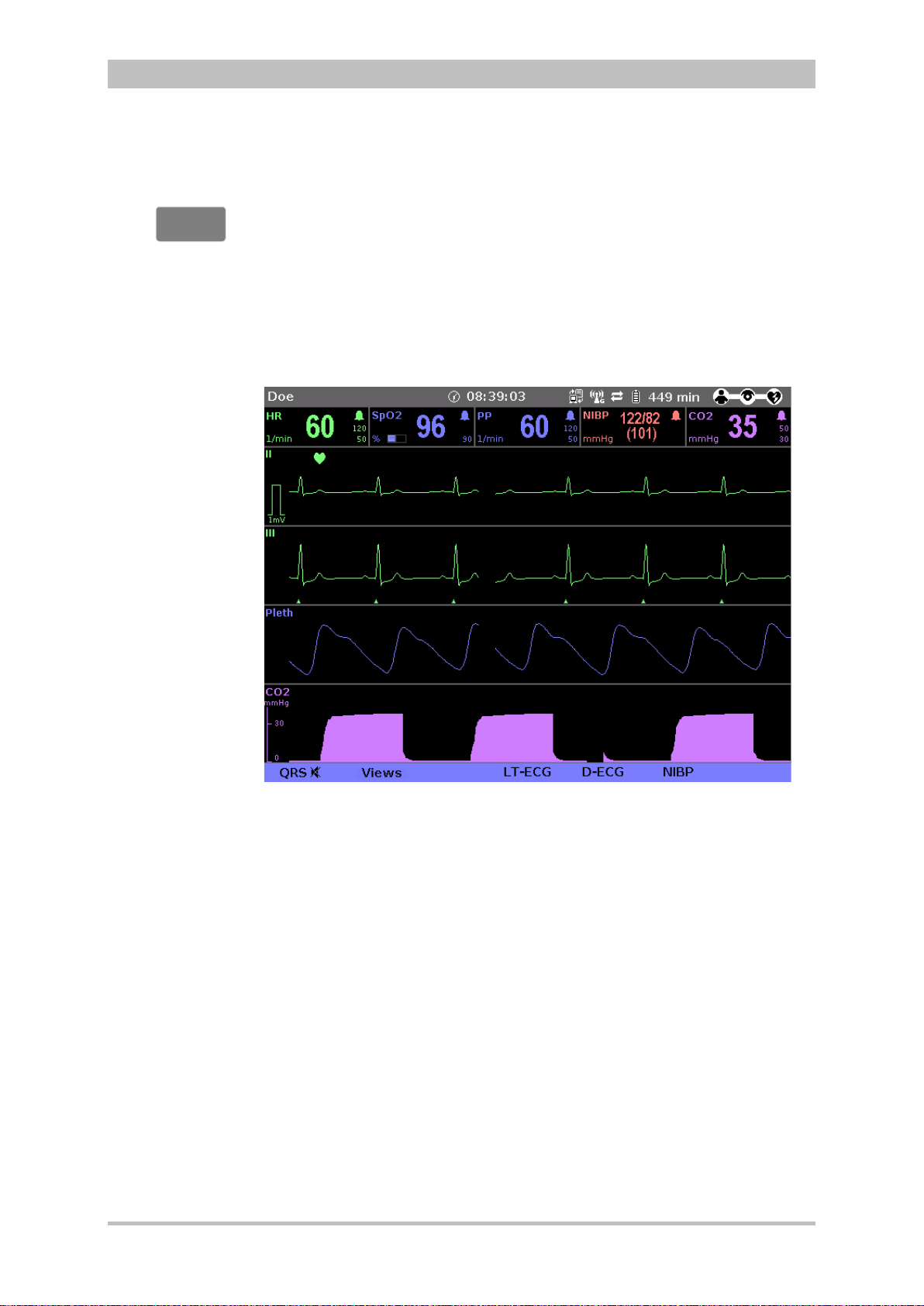
General Operating Instructions
Screen inverted
video display
Monitor
Screen
Night vision
goggle
-
compatibility
If necessary under particular lighting conditions, the screen can be displayed in
inverted video. If the Monitor key is held down for more than 3 seconds, the
screen display is inverted (see also chapter 7.1.1 General System Settings,
p. 137). Furthermore, it is possible to invert the screen via the system settings: .
1. Select in the main menu the menu item "System" ► "Settings".
The configuration dialogue opens.
2. In the configuration group "Display" select the configuration field "Colours"
► "Inverted".
3. Press the softkey [OK].
User Manual corpuls
3
(NVG/NVIS)
Fig. 4-4 Inverted video display of the screen (colours may differ)
The corpuls
3
is optionally available as a night vision goggle (NVG/NVIS)compatible variant (see chapter 9.8 Approved Accessories, Spare Parts and
Consumables, page 224) This variant emits less light than normally so that in-
3
flight or military purpose operation of the corpuls
when using night vision
goggles is possible.
For this, the display of the screen of night vis ion gog gl e (NVG/NVIS)-compatible
devices can be inverted specif ically for use with night vision goggles via the
system settings (see chapter 7.1.1 General System Settings, page 137): :
1. Select in the main menu the menu item "System" ► "Settings".
The configuration dialogue opens.
2. In the configuration group "Display" select the configuration field "Colours"
► "Night".
3. Press the softkey [OK].
4. If this configuration should be available automatically with the next system
start, it has to be saved (see chapter 7.4.2 General System Settings
(Person responsible for the device), page 160).
38 ENG - Version 2.1 – P/N 04130.2
Page 51

User Manual corpuls
2
3
1
2
3
1
))
X
Note
3
General Operating Instructions
4.1.3 Patient Box Display
The patient data are displayed on a separate screen during modular use. The
screen has the following structure:
Fig. 4-5 Patient box, displays on the screen (illustration may differ)
1 Connection status with the monitoring unit
2 Remaining running time of the patient box on battery operation
3 Display of a selected vital parameter
For the status of the network connection (item 1) of the patient box, the
following conditions exist:
Connection status Meaning
The patient box has a connection with the
Table 4-3 Connection status of the modules
The remaining running time is not displayed if the patient box is operated on an
external mains charger.
The screen of the patient box may appear darker in night vision goggle
(NVG/NVIS)-compatible devices.
monitoring unit
The patient box does not have a connection with
the monitoring unit
ENG - Version 2.1 – P/N 04130.2 39
Page 52
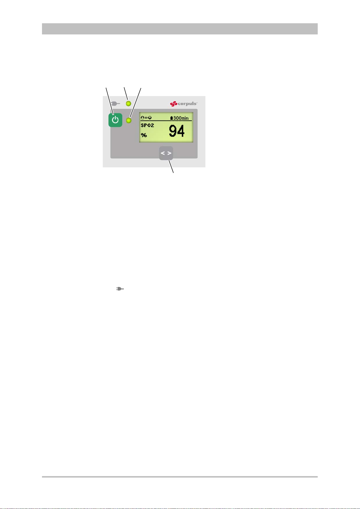
General Operating Instructions
2
4
3
1
LED
green
orange
On/Off key
LED
power supply/
arging status
Multifunction
LED
Multifunction key
Note
4.1.4 Control Keys and LEDs on the Patient Box
Fig. 4-6 Patient box, control keys and LEDs
The patient box is switched on or off during modular use by pressing the On/Off
key (item 1).
The state of charge LED (item 2) indicates the power supply or the state of
charge of the battery:
ch
power supply/
(illustration may differ)
1 On/Off key
2 LED power supply/charging status
3 Multifunction LED operating status/HR/alarm
4 Multifunction key
- battery is fully charged
charging status
device is connected to the mains
power supply
User Manual corpuls
3
40 ENG - Version 2.1 – P/N 04130.2
- battery is being charged
The multifunction LED (item 3) flashes in step with the heart rate when ECG
electrodes or the SpO
sensor are connected. If no electrodes or no SpO2
2
sensor are connected, it indicates the operating status of the patient box.
Furthermore, physiological and technical alarms are indicated by flashing up.
By pressing the multifunction key (item 4), the next parameter being currently
measured is displayed.
If alarms are displayed on the screen of the patient box, they can be confirmed
by pressing the multifunction key.
When the device is equipped with night visi on gog gl e (NVG/NVIS)-compatibility,
the LED power supply/chargin g status and the m ultifunction LED glow yellow
instead of orange.
Page 53

User Manual corpuls
LED
green
orange
LED operati
green
On/Off key
Status LEDs on
defibrillator
Note
3
4.1.5 Control Key and LEDs
on the Defibrillator/Pacer
General Operating Instructions
Fig. 4-7 Defibrillator, control key and status LEDs
1 On/Off key
2 Operating status LED
3 Power supply/charging status LED
By pressing the On/Off key (item 1), the defibrillator is switched on or off during
modular use.
The status LEDs of the defibrillator/pacer module indicate the power supply or
state of charge of the battery as well as the operating status of the device:
power supply/
state of charge (item 3)
- battery is fully charged
device is connected to the mains
power supply
- battery is being charged
ng status (item 2)
- device is switched on
When the device is equipped with night visi on gog gl e (NVG/NVIS)-compatibility,
the LED power supply/chargin g status and the m ultifunction LED glow yellow
instead of orange.
ENG - Version 2.1 – P/N 04130.2 41
Page 54

General Operating Instructions
LED
green
orange
LED operating status (item 2)
green
On/Off key
Status LEDs on
defibrillator
Note
4.1.6 Control Key and LEDs on the Defibrillator/Pacer SLIM
Fig. 4-8 Defibrillator SLIM, control key and status LEDs
By pressing the On/Off key (item 1), the defibrillator is switched on or off during
modular use.
The status LEDs of the defibrillator/pacer module indicate the power supply or
state of charge of the battery as well as the operating status of the device:
1 On/Off key
2 Operating status LED
3 Power supply/charging status LED
User Manual corpuls
3
power supply/
state of charge (item 3)
- battery is fully charged
device is connected to the mains
power supply
- battery is being charged
- device is switched on
When the device is equipped with night visi on gog gl e (NVG/NVIS)-compatibility,
the LED power supply/charging status and the multifunction LED glow yellow
instead of orange.
42 ENG - Version 2.1 – P/N 04130.2
Page 55
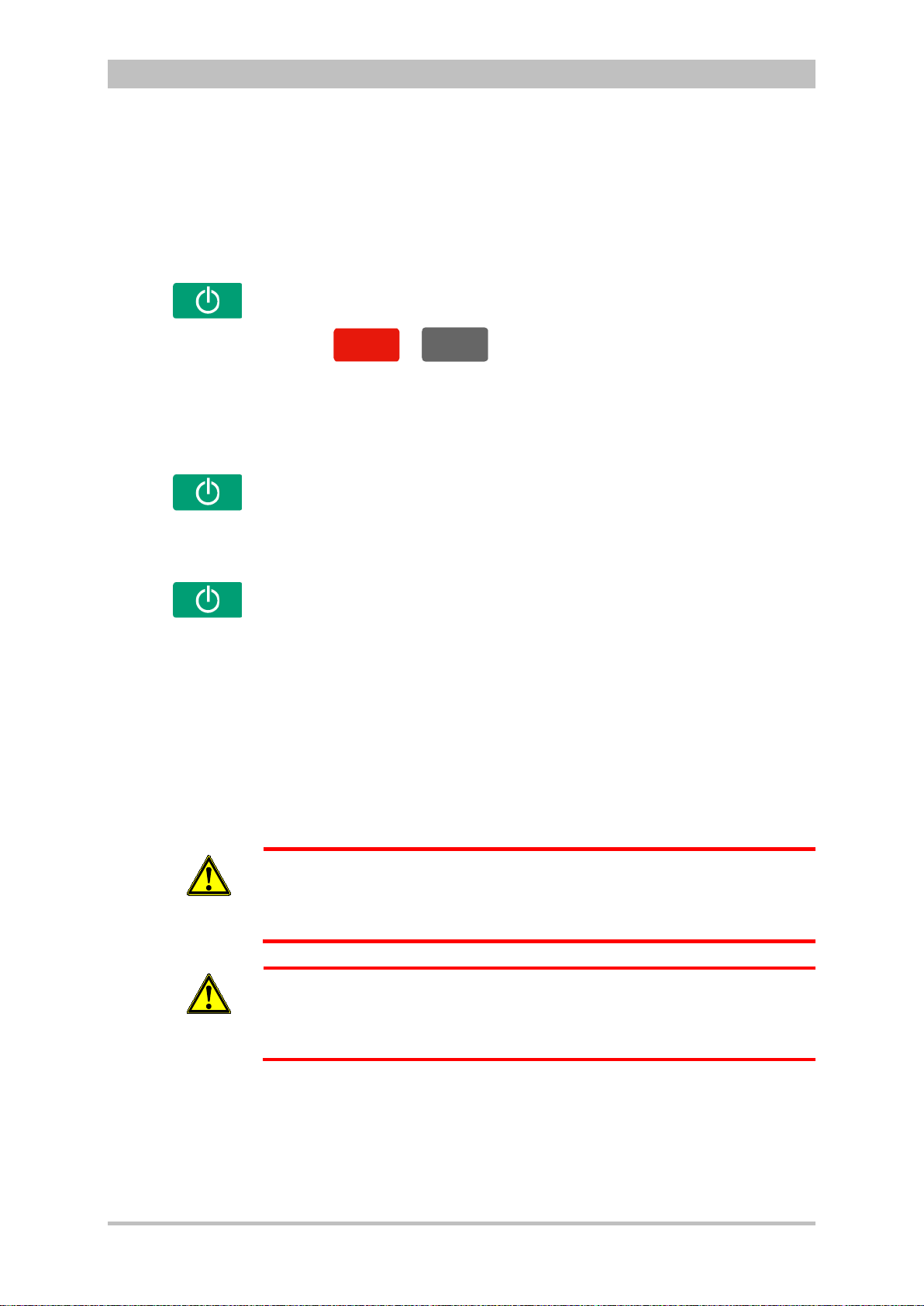
User Manual corpuls
AED
Man
ue
ll
Manual
Compact device
Semi modular
use
Modular use
Connecting
modules
Note
Switching on in
tion
mode
Note
3
4.2 Switching On and Off
4.2.1 Switching On
Press the On/Off key on the monitoring unit.
All modules are switched on.
General Operating Instructions
defibrilla
Press the
The corpuls
or
3
either starts in AED mode or in manual defibrillation mode,
key on the monitoring unit.
respectively.
1. Press the On/Off key on the monitoring unit.
The monitoring unit and the module connected mechanically to it are
switched on.
2. Press the On/Off key on the module which is not connected mechanically.
This module is switched on.
Press the On/Off key on all individual modules.
The modules are switched on independently.
When a switched-off module is connected mechanically to a switched-on
module, it switches on automatically.
If a battery is inserted into a module, this module switches on automatically.
A certain amount of time is required to achieve operational status after
3
switching on. It is therefore recommended to switch on the corpuls
as soon
as possible.
If the alarm message „ß SW-NOT FOR PAT. USE“ appears after the device is
switched on, the software of one or all modules is a betaversion.
Warning
Using this version on a patient is prohibited. Please contact your sales and
service partner.
If the alarm message „ONLY FOR TEST PURPOSE“ appears after the device
is switched on, the software of one or all modules is a test version.
Warning
Using this version on a patient is prohibited. Please contact your sales and
service partner.
ENG - Version 2.1 – P/N 04130.2 43
Page 56

General Operating Instructions
In order to switch off the compact device in case of a system crash the
Cancelling
off
Compact device
(Semi) modular use
Defibrillator/patient box
Switching off
in case of
system crash
Switching off in
pacer mode
4.2.2 Switching Off
Press the On/Off key on the monitoring unit.
All modules are switched off if the softkey [OK] is pressed after the confirmation
prompt appears.
Fig. 4-9 Confirmation prompt before switching off
Press the On/Off key on the monitoring unit.
All modules connected with the monitor unit mechanically or by radio are
switched off if the s of tkey [OK] is pressed af t er th e c o nf irmation prompt appears .
The defibrillator and patient box can be switched off independently without
having an influence on the remaining modules by pressing the On/Off key. To
do so, keep the On/Off key on the defibrillator or patient box depressed for 3
seconds.
In case of a system crash of one of the modules or of the compact device, the
device can be switched off with the On/Off key. For this, the On/Off key at the
monitoring unit (or at the individual modules) has to be held down at least for 8
seconds until the device switches off. Subsequently, the. It is not necessary to
remove the battery.
User Manual corpuls
3
modules have to be disconnected and every individual module has to be
Warning
switched off separately by holding down the On/Off key at the respective
module for 8 seconds.
The switch-off process of the monitoring unit and the connected modules can
switch-
be cancelled by pressing the softkey [Cancel]. This confirmation prompt
disappears by itself if no action is taken within approx. 10 seconds and the
monitoring unit and the connected modules remain switched on.
To confirm the switching off process, press the softkey [OK].
Press the On/Off key as described above.
The confirmation prompt “Switch off Pacer? - Power OFF?" appears.
Fig. 4-10 Switching off with pacer active
If the unit is to be switched off even though the pacer is active, press softkey
44 ENG - Version 2.1 – P/N 04130.2
[OK] or, if the unit is not to be switched off, press softkey [Cancel].
Page 57

User Manual corpuls
Warnings on
switching off
3
General Operating Instructions
If no connection with the patient box and/or defibrillator/pacer exists at the time
of switching off the monitoring unit or if a timing problem exists between the
modules, this is indicated to the user by the message “Check modules”:
Fig. 4-11 Warning on switching off
In this case, separate the modules and check whether all modules have been
shut down. If this is not the case, switch off the modules which have not been
switched off by pressing the respective On/Off key.
ENG - Version 2.1 – P/N 04130.2 45
Page 58
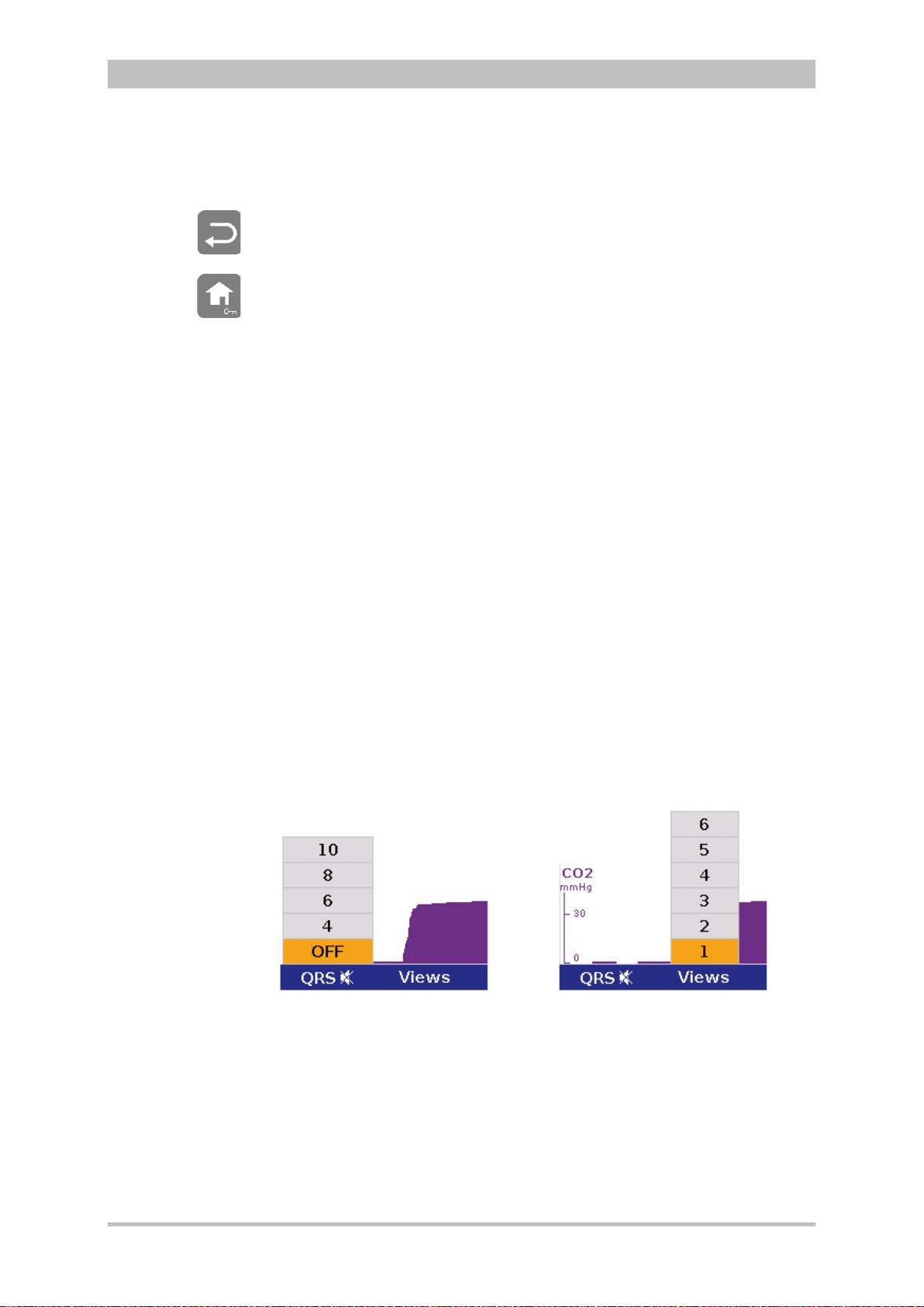
General Operating Instructions
Softkey QRS
and Views
4.3 Menu Control
The menus are controlled with the jog dial, softkeys and the function keys Back
and Home.
There are four different menu types:
• softkey context menu
• parameter context menu or curve context menu
• main menu of the device
• configuration dialogue
4.3.1 Softkey Context Menu
The softkey context menu allow for fast access to menu items that are relevant
for the chosen softkey.
There are three softkey context menus available:
• QRS: activation of the QRS tone and fast access to volume control
(monitoring mode)
• Views: fast access to a configured view of parameters and curves
(monitoring mode)
• Metronome: fast access to mode selection
In monitoring mode the two first softkeys (left) are linked to the settings for the
volume of the QRS tone and to the selection of views on the screen.
The settings can be advanced position by position by pressing the softkey
several times. In contrast to the softkey Views, the volume control of the QRS
tone always starts with the position, „OFF“.
User Manual corpuls
3
46 ENG - Version 2.1 – P/N 04130.2
Fig. 4-12 Example for softkey context menu
Page 59
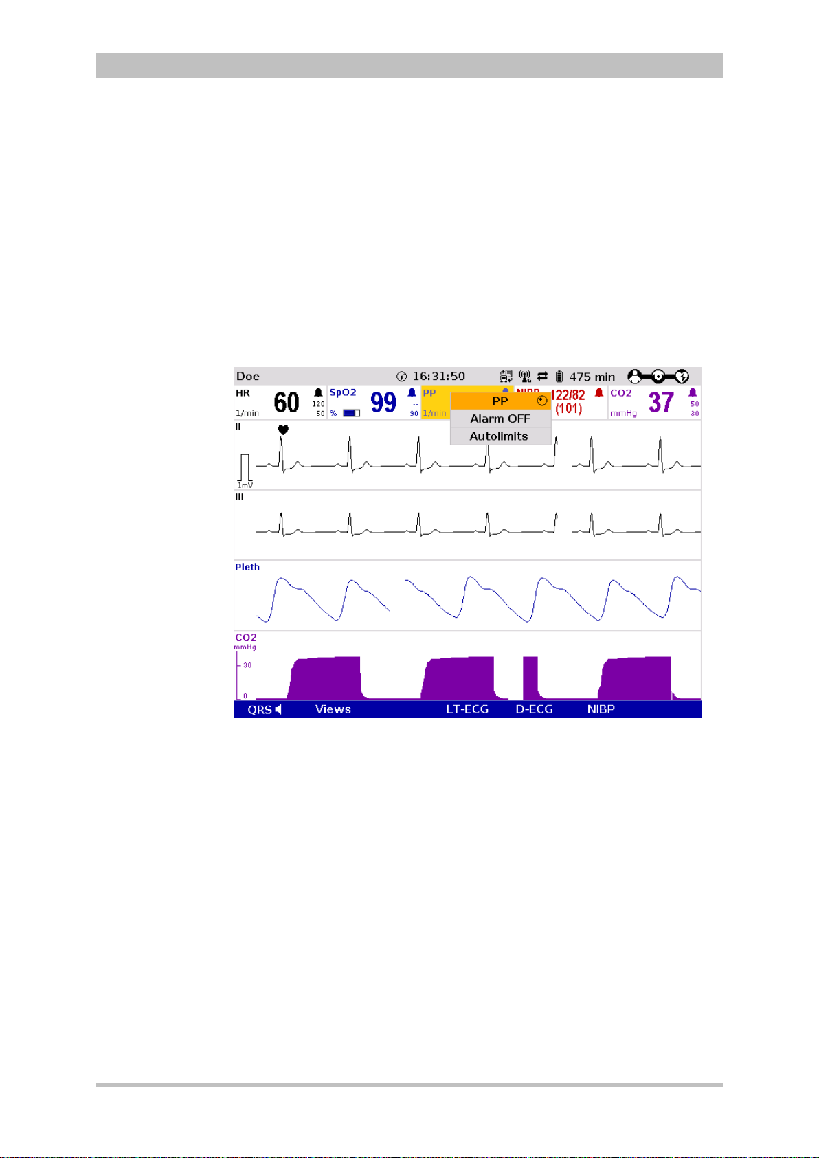
User Manual corpuls
3
General Operating Instructions
4.3.2 Parameter Context Menu and Curve Context Menu
Parameter context menus and curve context menus only contain menu items
that are relevant for the highlighted field. They can be called up for parameter
fields and curve fields and open directly in the highlighted field.
Proceed as follows to open a parameter context menu or curve context menu
and adjust settings:
1. Rotate the jog dial to highlight the required parameter field or curve.
2. Press the jog dial to open the parameter context menu or curve context
menu of the highlighted parameter field or curve. The first line of the
parameter context menu or curve context menu is highlighted.
Fig. 4-13 Parameter context menu (illustration may differ)
ENG - Version 2.1 – P/N 04130.2 47
Page 60

General Operating Instructions
Note
User Manual corpuls
3
Fig. 4-14 Curve context menu
3. If another value is to be assigned to the parameter field or the curve field
for display, press the jog dial and select the required parameter by rotating.
4. Press the jog dial again to confirm selection of the required parameter.
5. Select further parameters of the parameter context menu or curve context
menu by rotating the jog dial and confirm by pressing the jog dial.
Press the Home key to quit the parameter context menu or curve context menu.
If a new curve is selected in the curve context menu, the curves are sorted
automatically in ascending order .
48 ENG - Version 2.1 – P/N 04130.2
Page 61

User Manual corpuls
3
General Operating Instructions
4.3.3 Main Menu
To select the main menu of the device and adjust settings, proceed as follows:
1. Press the jog dial to open the main menu of the device.
Fig. 4-15 Main menu
2. Select the required item in the main menu by rotating the jog dial and
confirm by pressing the jog dial.
3. Select the required menu item in the submenu by rotating the jog dial and
confirm by pressing the jog dial.
4. The corresponding configuration dialogue opens.
ENG - Version 2.1 – P/N 04130.2 49
Page 62
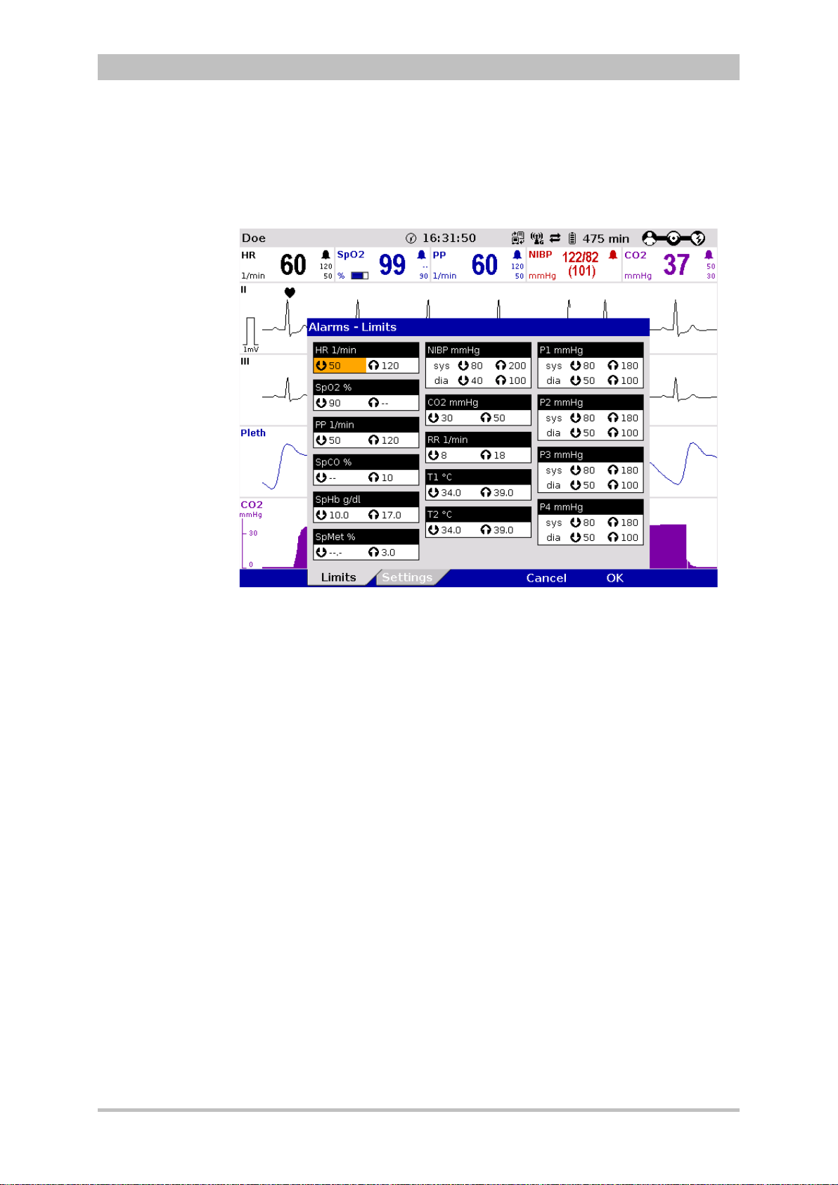
General Operating Instructions
Note
4.3.4 Configuration Dialogue
To adjust settings in the configuration dialogue, proceed as follows:
User Manual corpuls
3
Fig. 4-16 Configuration dialogue
1. Open the configuration dialogue (see chapter 4.3.3 Main Menu, p. 49).
2. Rotate the jog dial to highlight the required configuration field.
3. Press the jog dial to select the highlighted configuration field.
4. Select the required settings by repeatedly rotating and pressing the jog dial.
A setting (numerical value, text or symbol) can be modified if
• the respective line is highlighted;
• the setting is displayed in bold type.
See chapter 7 Configuration, p. 137 for information on the possible settings.
5. Access another tab of the configuration pages by pressing the
corresponding softkey.
6. To confirm the settings and close the configuration dialogue, press the
softkey [OK].
To retain the previous settings and close the configuration dialogue, press
the softkey [Cancel].
50 ENG - Version 2.1 – P/N 04130.2
Page 63
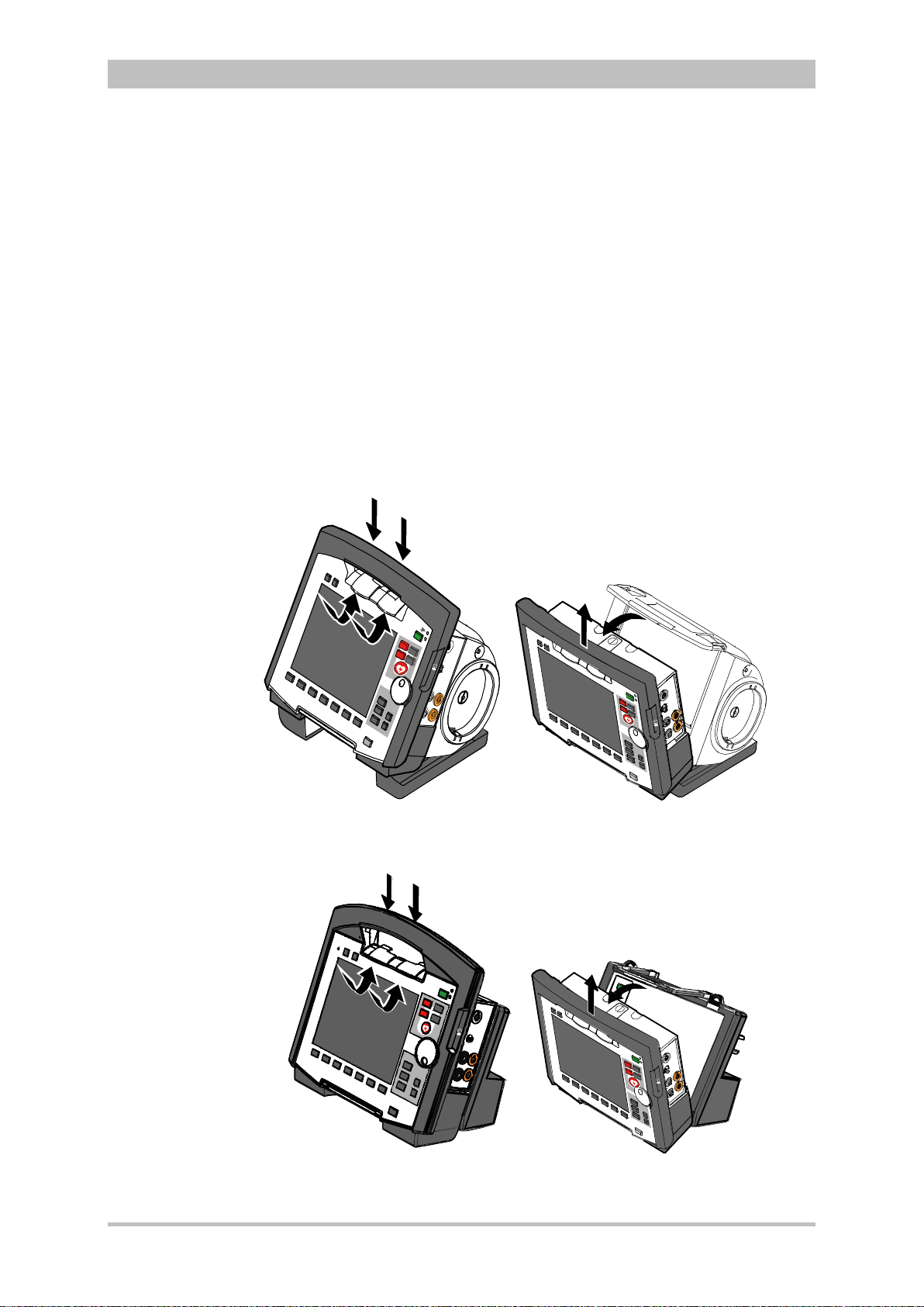
User Manual corpuls
C
A
B
D
C
D
A
B
Note
Note
3
General Operating Instructions
4.4 Disconnecting and Connecting Modules
The separating or connecting of modules should be avoided, if possible, when
verbal instructions are being played as they can be interrupted.
4.4.1 Disconnecting the Monitoring Unit from the
Defibrillator/Pacer
This procedure applies regardless of whether the patient box is connected to
the monitoring unit or not.
1. Grasp the monitoring unit by the carrying handle and pull both snap locks
simultaneously forwards and upwards with your thumbs (item A) or push
them rearwards and downwards (item B).
2. Tilt the monitoring unit forwards (item C) and remove upwards (item D).
Fig. 4-17 Disconnecting the monitoring unit from the defibrillator/pacer
(illustration may differ)
Fig. 4-18 Disconnecting the monitoring unit from the defibrillator/pacer SLIM
(illustration may differ)
ENG - Version 2.1 – P/N 04130.2 51
Page 64
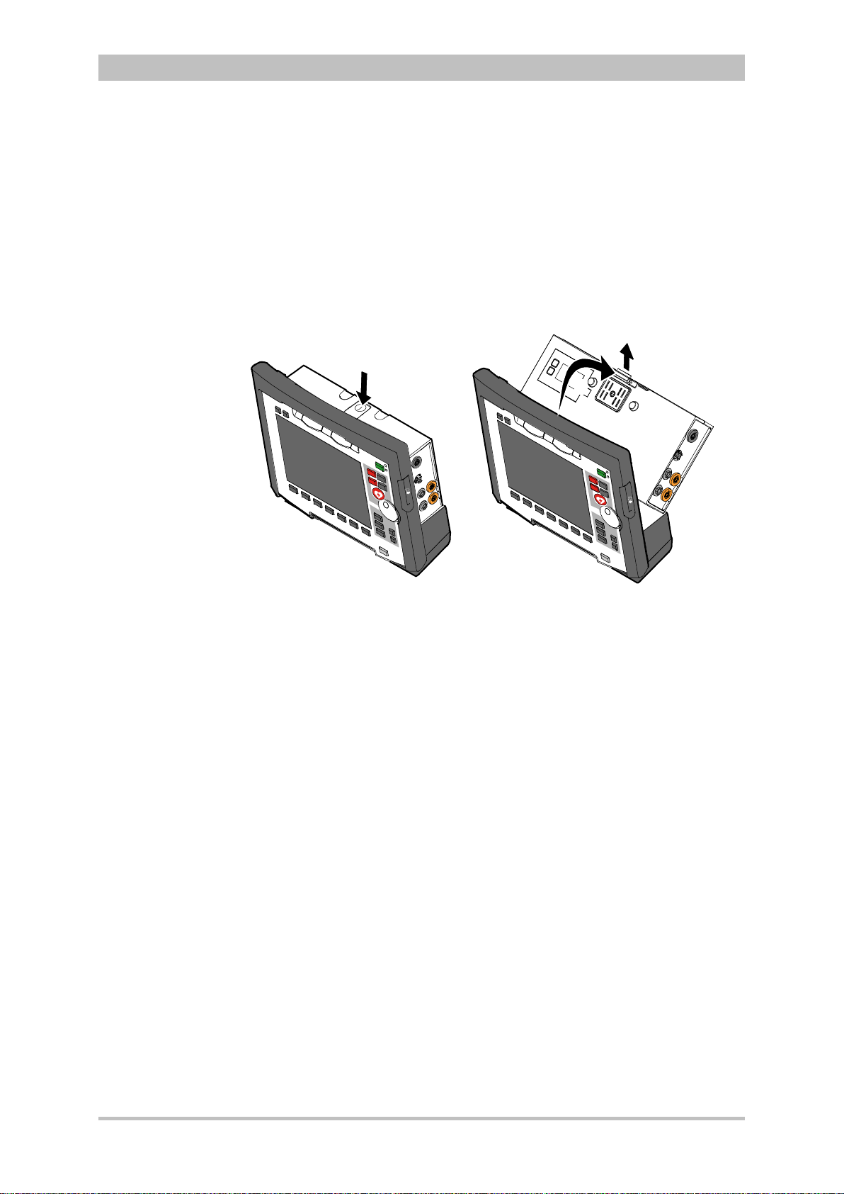
General Operating Instructions
A
C
B
4.4.2 Disconnecting the Patient Box from the Monitoring
Unit
1. Grasp the monitoring unit by the carrying handle and press the snap lock of
the patient box downwards (item A).
2. Tilt the patient box rearwards (item B) and remove from the monitoring unit
(item C).
User Manual corpuls
3
Fig. 4-19 Disconnecting the patient box from the monitoring unit (illustration
may differ)
52 ENG - Version 2.1 – P/N 04130.2
Page 65

User Manual corpuls
3
General Operating Instructions
4.4.3 Connecting the Patient Box to the Monitoring Unit
1. Position the patient box with the display facing the monitoring unit.
2. Fit the patient box at the bottom on the monitoring unit (item A):
The recesses (item 3) of the patient box engage in the two pins (item 5) of
the monitoring unit.
The connection coding (item 6) on the monitoring unit fits into the recess
(item 4) on the patient box.
3. Tilt the patient box towards the monitoring unit (item B) until the closure at
the top (item 2) of the patient box audibly engages in the catch on the
monitoring unit (item 1).
4. Make sure that the patient box is engaged in both the pins and recesses at
the bottom and in the closure at the top.
Attention
Fig. 4-20 Connecting the patient box to the monitoring unit (illustration may
differ)
1 Catch
2 Closure
3 Recess
4 Connection coding recess
5 Pin
6 Connection coding
Before connecting the modules, make sure that there are no metallic objects,
e. g. conductive foils, between the individual modules.
ENG - Version 2.1 – P/N 04130.2 53
Page 66
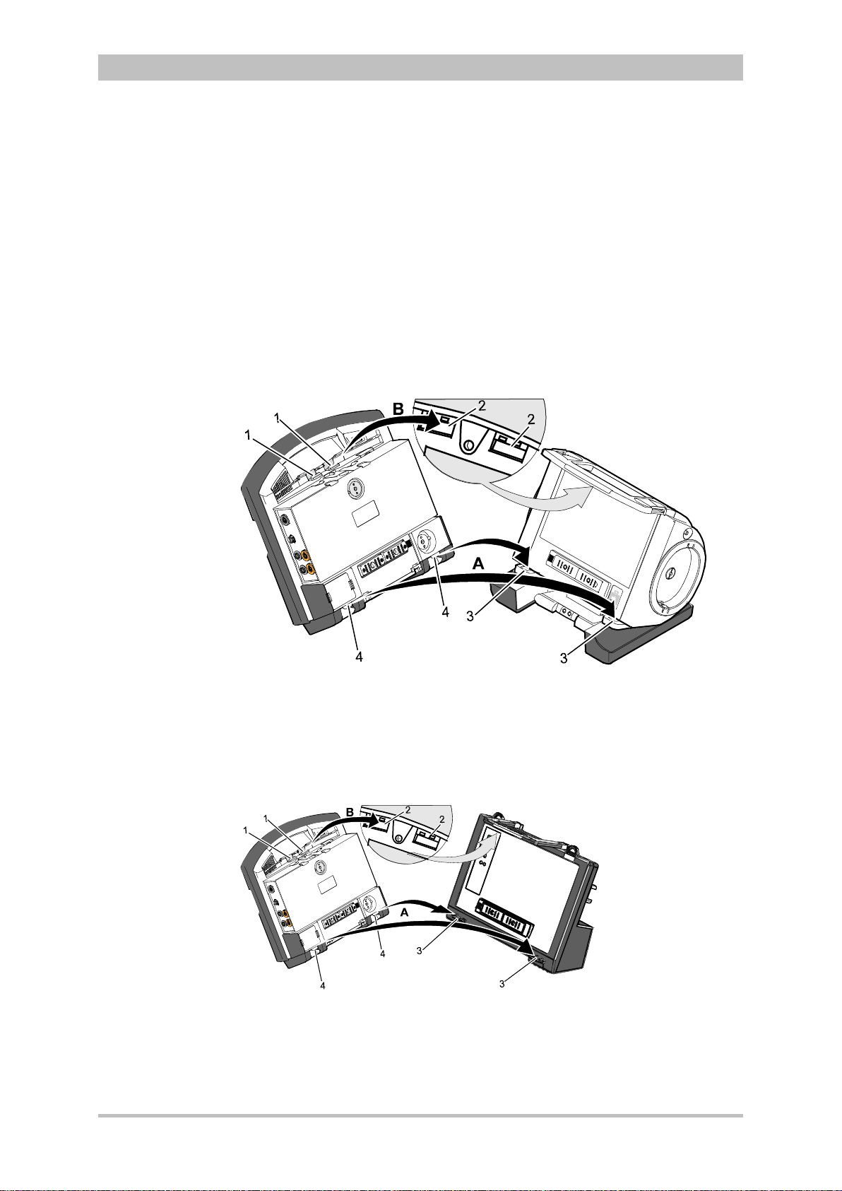
General Operating Instructions
Note
4.4.4 Connecting the Monitoring Unit to the
Defibrillator/Pacer
This procedure applies regardless of whether the patient box is connected to
the monitoring unit or not.
1. Raise and tilt the monitoring unit forwards.
2. Fit the monitoring unit onto the defibrillator/pacer at the bottom (item A):
Both pins (item 4) of the monitoring unit engage in the two recesses (item
3) on top of the base of the defibrillator/pacer.
3. Tilt the monitoring unit towards the defibrillator/pacer (item B) until the
closures at the top (item 1) of the monitoring unit audibly engage in the
recesses (item 2) on the defibrillator/pacer.
User Manual corpuls
3
Fig. 4-21 Connecting the monitoring unit to the defibrillator/pacer (illustration
may differ)
1 Closure
2 Recess for closure
3 Recess on top of base
4 Pin
Fig. 4-22 Connecting the monitoring unit to the defibrillator/pacer SLIM
(illustration may differ)
1 Closure
2 Recess for closure
3 Recess on top of base
4 Pin
54 ENG - Version 2.1 – P/N 04130.2
Page 67
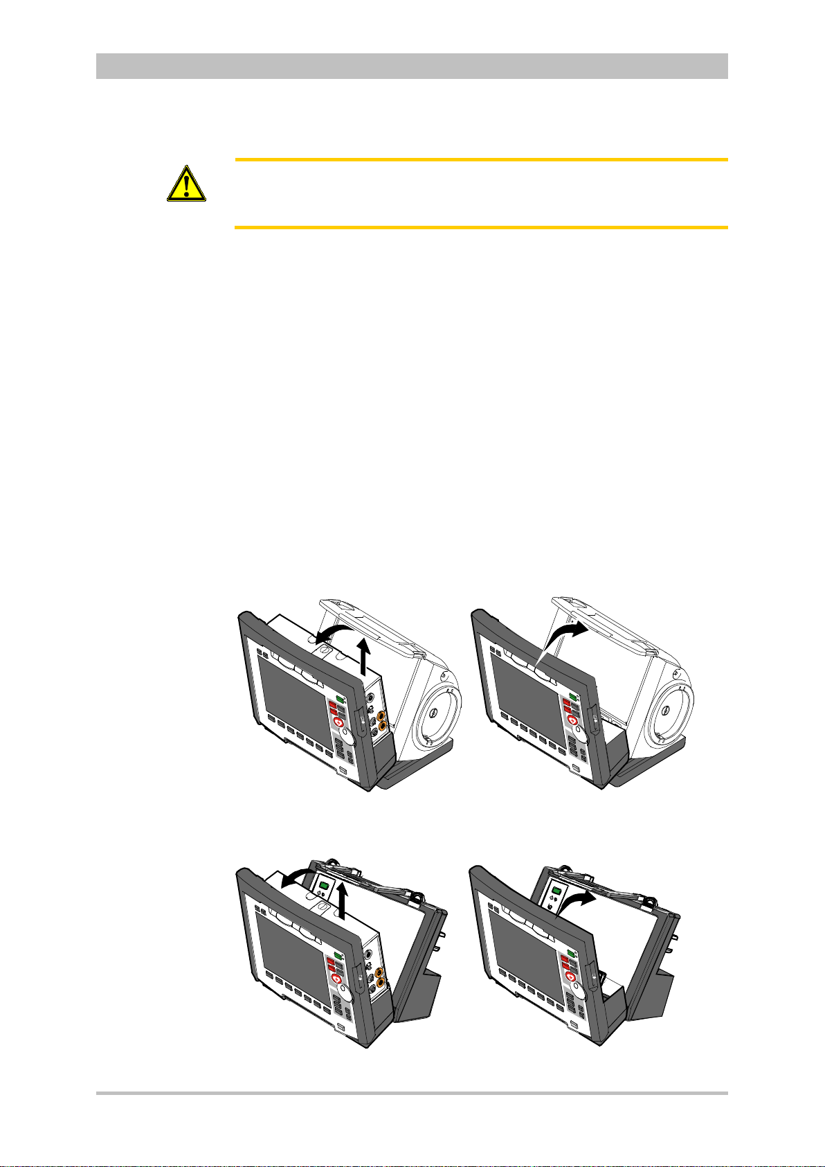
User Manual corpuls
A
C
B
A
B
C
Attention
3
Before connecting the modules, make sure that there are no metallic objects,
e. g. conductive foils, between the individual modules.
General Operating Instructions
4.4.5 Removing the Patient Box from the Compact
Device
1. Grasp the monitoring unit by the carrying handle and pull both snap locks
simultaneously forwards and upwards with your thumbs or push them
rearwards and downwards.
2. Tilt the monitoring unit with the patient box forwards (item A) (see
chapter 4.4.1 D isconn ectin g the Monit oring U nit from the D efibri llator/ Pacer ,
p. 51).
3. Push the snap lock of the patient box downwards.
4. Tilt the patient box backwards and remove upwards from the monitoring
unit (item B) (see chapter 4.4.2 Disconnecting the Patient Box from the
Monitoring Unit, p. 52.).
5. Tilt the monitoring unit towards the defibrillator/pacer until the closures at
the top of the monitoring unit audibly engage in the recesses on the
defibrillator/pacer (see chapter 4.4.4 Connecting the Monitoring Unit to the
Defibrillator/Pacer, p. 54).
Fig. 4-23 Removing the patient box from the compact device (illustration may
differ)
Fig. 4-24 Removing the patient box from the compact device with
ENG - Version 2.1 – P/N 04130.2 55
defibrillator/pacer SLIM
Page 68
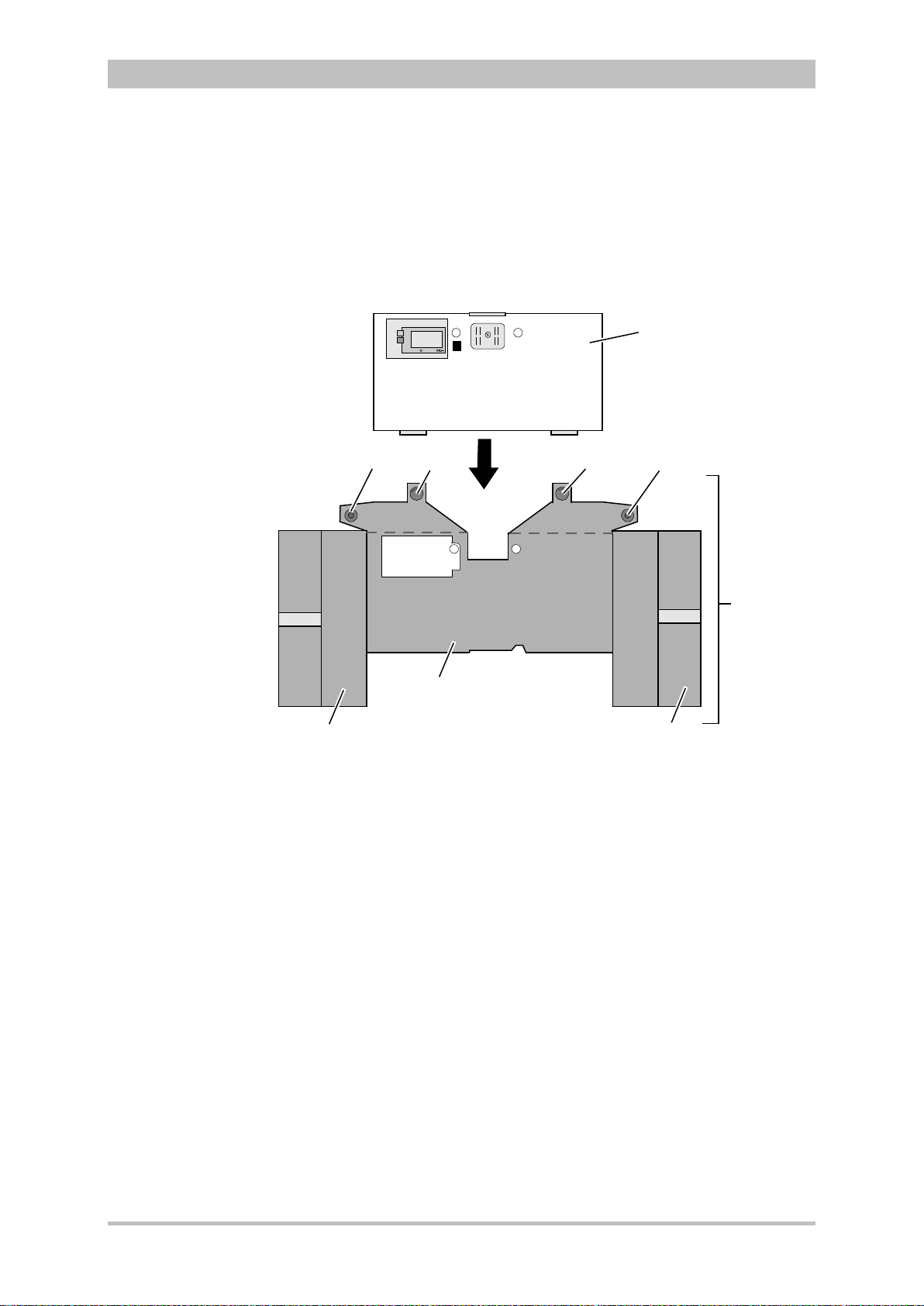
General Operating Instructions
1
3
4
2
4
3
7
6
5
4.5 Accessory Bag
4.5.1 Fitting the Accessory Bag
1. Insert the patient box (item 1) into the protective cover (item 6).
User Manual corpuls
3
Fig. 4-25 Accessory bag and patient box, front view (illustration may differ)
1 Patient box
2 Accessory bag
3 Lateral press stud
4 Rear press stud
5 Right-hand bag
6 Protective cover
7 Left-hand bag
2. Insert the two flaps with the lateral press studs (item 3) laterally from the
patient box.
3. Open the zip fasteners of the left-hand and right-hand bags (items 5 and 7)
and press the lateral press studs firmly in place inside on the upper sides of
the bags.
4. Close the rear press studs (item 4) on the protective cover.
56 ENG - Version 2.1 – P/N 04130.2
Page 69
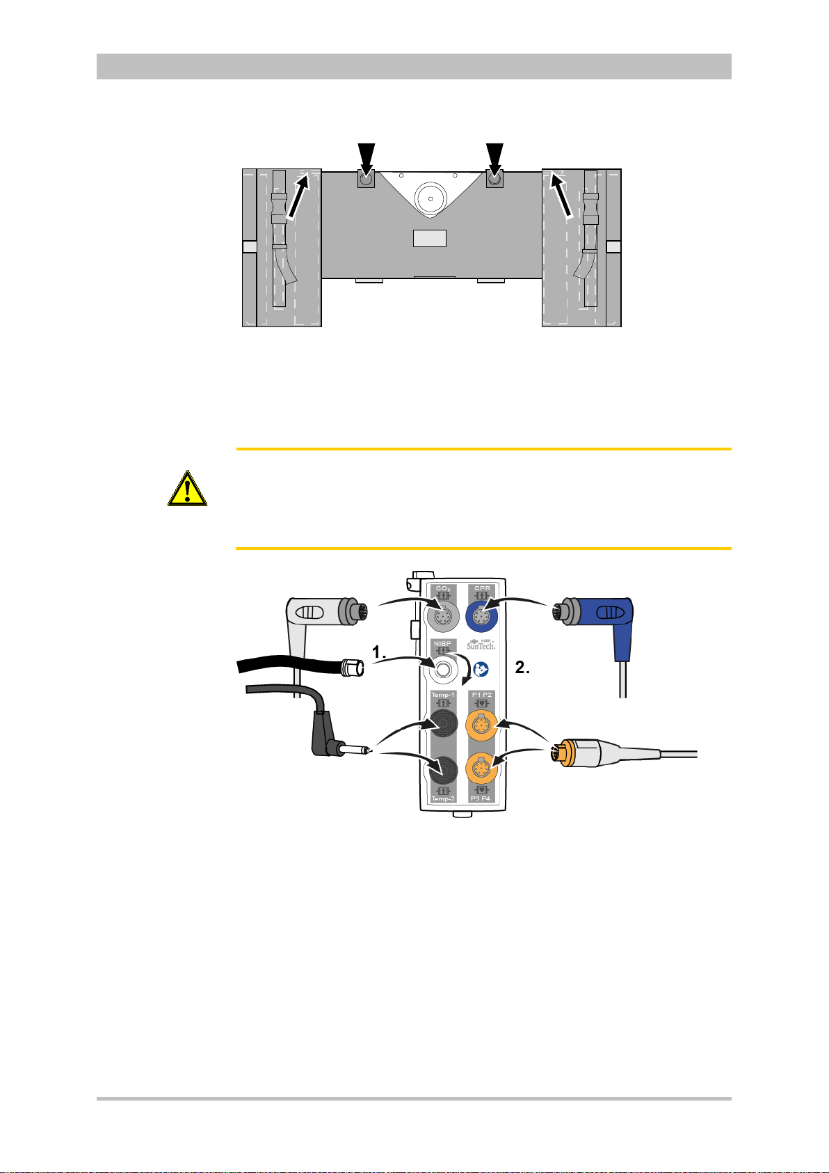
User Manual corpuls
Inserting cables
hand
side
3
General Operating Instructions
Fig. 4-26 Accessory bag with patient box, rear view (illustration may differ)
4.5.2 Packing the Accessory Bag
Caution
on right-
When inserting the sensor cables and ECG cables, make sure that the plugs
snap in place beyond the perceptible pressure point.
Fold (gather in loops) but do not roll up the connected cable to avoid
damage to the cable and allow rapid removal during mission without forming
knots.
Fig. 4-27 Inserting the plugs on the right-hand side of the patient box
ENG - Version 2.1 – P/N 04130.2 57
Page 70
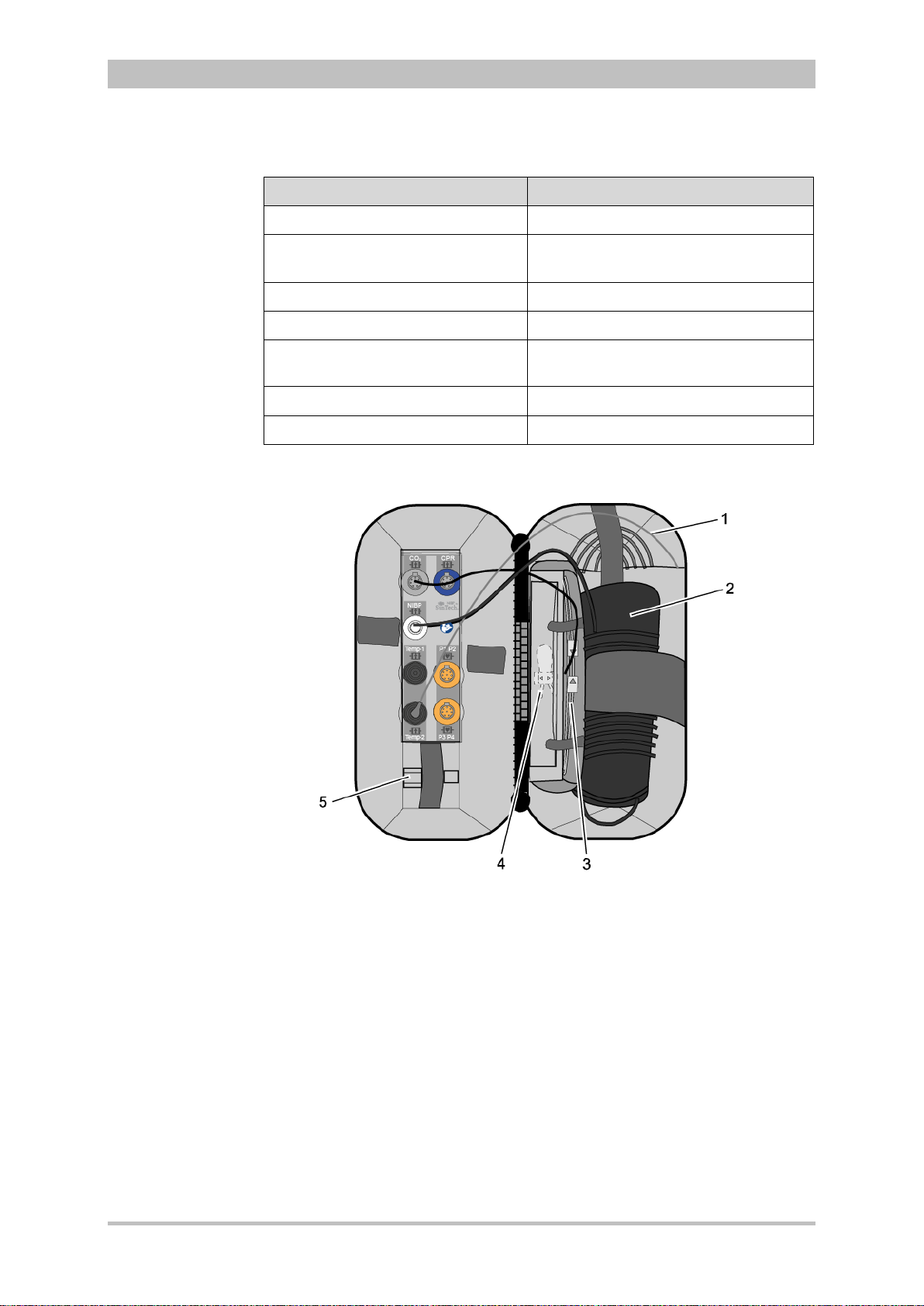
General Operating Instructions
Wide elastic band at the side of
Table
Right-hand bag
Note
Accessory Position
Temperature sensor (item 1) Outermost pocket
NIBP cuff (item 2)
CO2 sensor (item 4) Left-hand pocket on central section
CO2 intermediate cable (item 3) Right-hand pocket on central section
CO2 adapter, mainstream (item 5) Elastic band below the patient box
User Manual corpuls
outermost pocket
interfaces
3
corPatch CPR sensor
corPatch CPR intermediate cable
4-4 Contents of right-hand bag
Inner pocket
Inner pocket
58 ENG - Version 2.1 – P/N 04130.2
Fig. 4-28 Contents of right-hand bag (illustration may differ)
Only connect the temperature sensor to the patient box after attaching it to the
patient to avoid fals e a larm messages that indicate excessively low temperature.
Page 71

User Manual corpuls
Rainbow ECG-D
ECG-M
Table
1
2
4 5
6
3
Ra
inbo
w EC
G-D
Connecting
cables on
hand side
Left-hand bag
left-
3
General Operating Instructions
Fig. 4-29 Connecting the plugs on the left-hand side of the patient box
Accessory Position
4-pole ECG monitoring cable (item 1) Outermost pocket
Pack of ECG electrodes (item 2) Left-hand pocket on central section
Oximetry intermediate cable (item 3) Right-hand pocket on central section
Oximetry finger sensor (item 4) Elastic band on central section
Complementar y 6-pole ECG diagnostic
cable (item 5)
On the left next to the patient box
interfaces
Strain relief for right-angle plug (item 6) –
4-5 Contents of left-hand bag
Fig. 4-30 Contents of left-hand bag (illustration may differ)
ENG - Version 2.1 – P/N 04130.2 59
Page 72
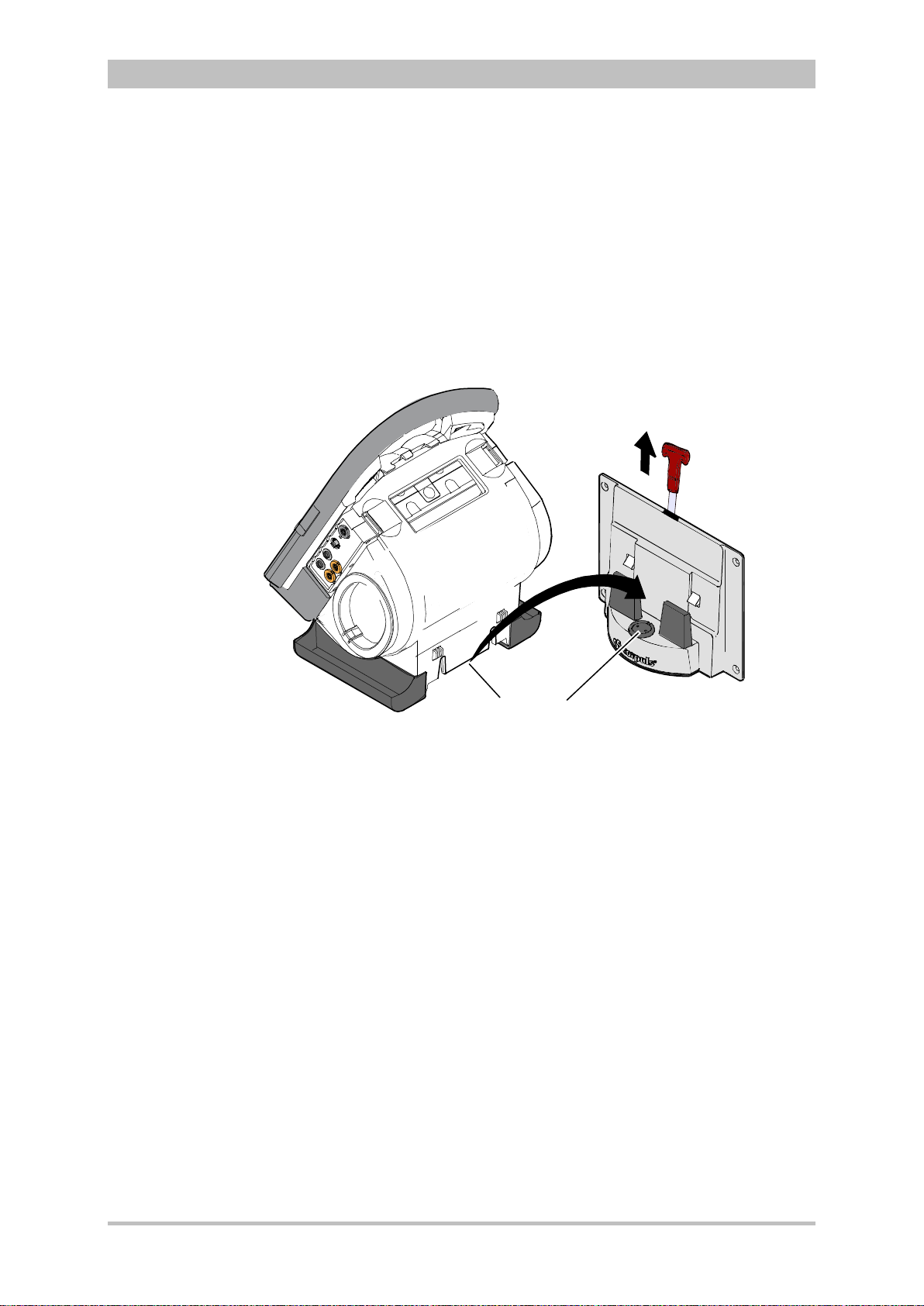
General Operating Instructions
B
A
1
2
Insertion
Removal
Note
Note
Insertion
4.6 Inserting the Device into the Brackets
4.6.1 Defibrillator/Compact Device Bracket
Fit the recesses at the bottom of the defibrillator onto the pins of the
defibrillator/compact device bracket (item A). The lock on the bracket engages
automatically.
If the bracket is equipped with a power supply, the defibrillator and all the
modules connected to it will be charged.
User Manual corpuls
3
Fig. 4-31 Inserting the compact device into the bracket (Illustration may differ)
1 Defibrillator/Pacer power supply contact area
2 Integrated magnetic clip
Pull the handle upwards (item B; in older brackets a loop) and remove the
defibrillator/compact device from the bracket.
Check the contact areas of the defibrillator/pacer (item 1) and the bracket
(item 2) regularly for contamination or foreign material, particularly metallic
items.
Remove the defibrillator/co mpact device within approx. 10 sec. after pulling the
handle, since the bracket automatically locks again.
60 ENG - Version 2.1 – P/N 04130.2
Page 73

User Manual corpuls
A
B
Insertion
Removal
Note
3
General Operating Instructions
4.6.2 Monitoring Unit Bracket
This procedure applies regardless of whether the patient box is connected to
the monitoring unit or not.
The monitoring unit is inserted into the bracket in the same manner as it is
connected to the defibrillator/pacer (see chapter 4.4.4 Connecting the
Monitoring Unit to the Defibrillator/Pacer, p. 54):
1. Raise and tilt the monitoring unit forwards.
2. Fit the monitoring unit onto the bracket at the bottom:
Both pins of the monitoring unit engage in the two recesses of the bracket
(item A).
3. Tilt the monitoring unit towards the bracket at the top until the closures at
the top of the monitoring unit audibly engage in the recesses on the bracket
(item B).
Fig. 4-32 Inserting the monitoring unit into the bracket (Illustration may differ)
The monitoring unit is removed from the bracket in the same manner as it is
disconnected to from the defibrillator/pacer (see chapter 4.4.1 Disconnecting
the Monitoring Unit from the Defibrillator/Pacer, p. 51):
1. Grasp the monitoring unit by the carrying handle and pull both snap locks
simultaneously forwards and upwards with your thumbs or push them
rearwards and downwards.
2. Tilt the monitoring unit forwards and remove upwards.
ENG - Version 2.1 – P/N 04130.2 61
Page 74
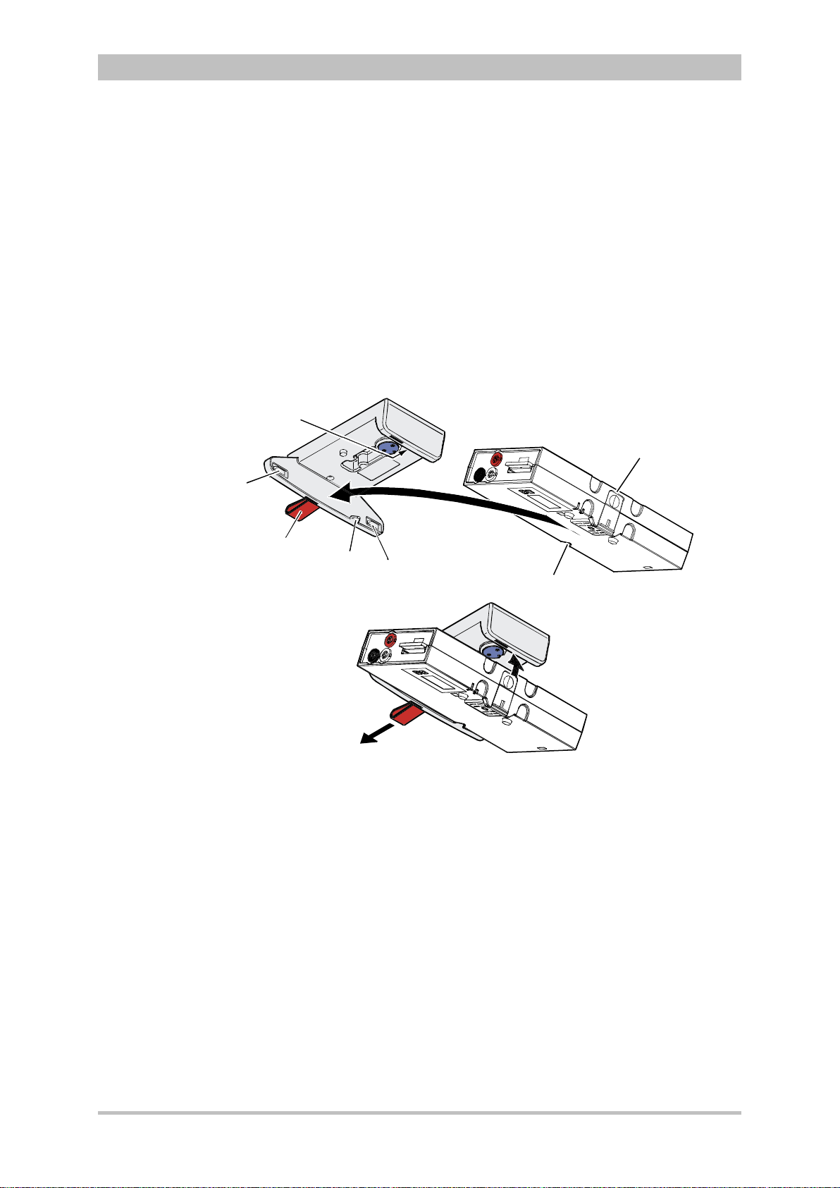
General Operating Instructions
1
4
5
2
3
6
4
A
B
C
Insertion
Removal Removal
4.6.3 Patient Box Charging Bracket
1. Position the patient box as shown in Fig. 4-33.
2. Fit the patient box with its bottom side onto the long part of the charging
bracket (item A):
The recesses on the patient box engage in both pins (item 4) on the
charging bracket.
The connection coding (item 5) fits in the recess (item 3) on the patient box.
3. Tilt the patient box upwards to the charging bracket (item B) until the lock
audibly engages at the patient box.
4. Make sure that the patient box is engaged in the guides and the closures.
5. Connect the safety belt below the patient box and pull tight (not illustrated).
User Manual corpuls
3
Fig. 4-33 Inserting the patient box into the charging bracket (ceiling
installation)
1 Lock
2 Closure
1. Disconnect the safety belt (not illustrated in Fig. 4-33).
3 Connection coding recess
4 Pins
5 Connection coding
6 Loop
2. Firmly hold the patient box and pull the loop (item 6) sideways (item C).
3. Remove the patient box from the bracket.
62 ENG - Version 2.1 – P/N 04130.2
Page 75

User Manual corpuls
Shock paddles
corPatch easy
electrodes
Baby shock
electrodes
Note
3
Operation – Therapy
5 Operation – Therapy
5.1 Therapy Electrodes for Defibrillati on and
Pacing
5.1.1 Types of Therapy Electrodes
With the introduction of the corPatch easy pre-connected therapy electrodes
(P/N 05120.1), for adults (P/N 04324.3) and Pediatric (P/N 05120.1) the higher
limits for the body weight of patients have been set. The manufacturer assures
that also the previously supplied therapy electrodes corPatch easy Neonate
(P/N 04324.2) can be used for defibrillations with an energy level of up to
100 Joule maximum and up to a body weight of 25 kg. The operational safety
as well as medical effectiveness of the therapy electrodes is guaranteed.
Various therapy electrodes are available for defibrillation and pacing:
Therapy electrodes Application Patient groups
Shock paddles Defibrillation,
Cardioversion,
ECG monitoring
Baby shock electrodes
(adapters for shock paddles)
corPatch easy electrodes
(disposable electrodes)
Internal shock spoons
(sterilisable)
Table 5-1 Therapy electrodes for defibrillation and pacing
The shock paddles can be used for defibrillation, synchronised cardioversion
and for ECG monitoring (DE recording). For using the shock paddles with the
defibrillator/pacer SLIM, an inter mediate adapter cable is needed.
Defibrillation, synchronised cardioversion and ECG monitoring of neonates and
infants is performed with baby shock electrodes (adapters) which are fitted onto
the shock paddles. The energy is automatically reduced at a ratio of 10:1 if the
adapters are fitted (see chapter 5.4.5 Manual Defibrillation and Cardioversion of
Neonates and Children, page 80).
corPatch easy electrodes are already connected to an electrode cable and
only need to be connected to the therapy master cable of the defibrillator/pacer.
The corPatch easy electrodes pre-connected for the defibrillator/pacer SLIM
can be pre-connected ev en before opening the package.
Defibrillation,
Cardioversion,
ECG monitoring
Defibrillation,
cardioversion,
ECG monitoring
Pacing
Defibrillation,
Cardioversion,
ECG monitoring
Adults/children
Neonates/infants up to
max. 5 kg body weight
Adults/children
Neonates/infants
Adults/children
Neonates/infants
ENG - Version 2.1 – P/N 04130.2 63
Page 76

Operation – Therapy
Internal shock
spoons
WARNING
WARNING
User Manual corpuls
The internal shock spoons consist of the shock spoon-electrodes and the
handles. Before use the electrodes have to be screwed onto the handles. The
handles are already connected to an electrode cable and only need to be
connected to the therapy master cable of the defibrillator/pacer.
To guarantee a defibrillation protection for patients, users and third parties,
use exclusively the accessories indicated in the list of authorised accessories
(see chapter 9.8 Approved Accessories, Spare Parts and Consumables,
page 224).
The following safety instructions which can also be found on every pouch of
the corPatch electrodes have to be complied with when using the
corPatch electrodes:
• Do not crush, bend, or fold electrodes or store them under heavy
objects.
• Do not open pouch until ready for use.
• Do not use corPatch electrodes if gel is dry.
3
Caution
Caution
• Do not use additional gel on corPatch electrodes.
• Do not overlap corPatch electrodes.
• Use separate ECG electrodes when performing non-invasive paci ng.
• Do not touch patient during defibrillation.
• Do not discharge shock paddles through corPatch electrodes.
• Keep corPatch electrodes clear of any other electrodes or metal
parts in contact with the patient.
Not following these instructions for the corPatch electrodes or any other
misuse or misapplication of the corPatch electrodes may result in severe
patient burns or ineffective therapy
Do not use corPatch electrodes if
• the packaging is damaged or opened;
• the expiry date indicated on the packaging has passed;
• the electrode or the connecting lug is bent.
Replace corPatch electrodes for adults at the latest after:
• 24 hours or 50 shocks;
• 8 hours of continuous pacer operation.
64 ENG - Version 2.1 – P/N 04130.2
Caution
WARNING
When placing the corPatch electrodes on the patient’s skin, make sure that
no air pockets are included inside the adhesive surface. Apply corPatch
electrodes from the centre outwards.
Before using the shock spoons, please read and understand the additional
user manual (P/N 04137.02).
Page 77
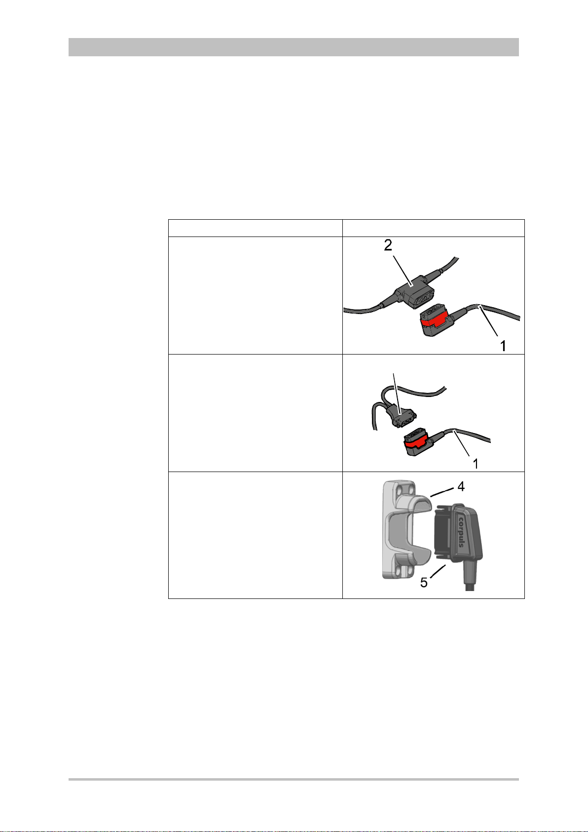
User Manual corpuls
3
Note
Note
3
Operation – Therapy
5.1.2 Connecting the Electrode Cable
To connect the therapy electrodes, connect the corresponding plug (item 2 or
item 3 in Fig 5-1) to the therapy master cable (item 1). To disconnect, pull back
the red sliding sleeve at the therapy master cable and pull apart the plugs. The
plug connectors are twistproof.
When using the defibrillator/pacer Slim the intermediate cable (item 5) has to be
connected to the therapy socket (item 4) at the rear side of the
defibrillator/pacer Slim.
Type of electrode Defibrillator/pacer
Shock paddles and shock spoons
Connect the plug of the shock
paddles or shock spoons (item 2) to
the plug of the therapy master cable
(item 1) of the defibrillator/pacer.
The connection must snap into place
perceptibly.
corPatch easy electrodes
(only P/N 04324.1 and 04324.2)
Connect the plug (item 3) of the
corPatch easy electrodes to the
plug of the therapy master cable
(item 1) of the defibrillator/ pacer.
The connection must snap into place
perceptibly.
Intermediate cable and corPatch
easy electrodes
(only P/N 05120.1, 05120.2 and
04324.3)
Connect the plug (item 5) correctly
orientated (item 1) to the therapy
socket (item 4) of the
defibrillator/pacer SLIM or to the
therapy master cable.
Fig. 5-1 Connecting the therapy electrode cables
1 Therapy master cable with plug and red sliding sleeve
2 Plug of shock paddles and shock spoons
3 Plug of corPatch easy electrodes
4 Therapy socket
5 Plug of corPatch intermediate cable
For orientation and correct connection of the plugs, a raised nub is palpable on
both the red sliding sleeve and the plug of the therapy electrodes (only P/N
04324.1 and 04324.2). W hen oriented corr ectly, the electrodes are easy to
connect.
For using the shock paddles with the defibrillator/pacer SLIM, an intermediate
adapter cable is needed (see chapter 9.8 Approved Accessories, Spare Parts
and Consumables, page 224).
ENG - Version 2.1 – P/N 04130.2 65
Page 78

Operation – Therapy
If the electrode plug is turned the wrong way and connected by force to the
A B
C
Removing the
shock paddles
Re-inserting the
shock paddles
Note
Caution
User Manual corpuls
therapy master cable, there will be a malfunction in the paddle interface and
an alarm message will be issued.
The plug connector has to be disconnected and checked for damage. If no
damage is visible, connect the plug connector again, oriented correctly.
5.1.3 Removing the Shock Paddles from their Holders and Re-inserting them
To remove the shock paddles from their holders at the defibrillator/pacer,
proceed as follows:
Prerequisite: The defibrillator/pacer is equipped with shock paddle holders.
1. Rotate the shock paddles by approx. 20° towards the front (item A) or
towards the rear (item B).
2. In this position pull the shock paddles away from the device (item C).
3
Fig. 5-2 Removing the shock paddles from their holders
To re-insert the shock paddles, push them into the holders until they both
perceptibly engage.
The shock paddle with the green button (APEX) is to be placed in the right-hand
holder and the shock paddle with the red button (STERNUM) in the left-hand
holder. For guidance, corresponding information labels are placed above the
holders.
66 ENG - Version 2.1 – P/N 04130.2
Page 79

User Manual corpuls
On metallic and/or wet surfaces the following protective measures have to be
Preparing the
patient
Patient
impedance
Caution
WARNING
3
Operation – Therapy
5.2 Preparing the Patient for Defibrillation, Cardioversion and Pacer The rapy
As a side effect of the defibrillation, a reddening of the skin and, in case of
excessive hair, burn injurie s m a y occur.
Recording of the ECG with therapy electrodes or via the 4 pole ECG
monitoring cable is impaired if the skin is contaminated or in case of
excessive hair.
Before therapeutic measures can be performed, the patient has to be prepared:
1. Remove clothes from the patient's upper body.
2. Remove any item of jewelry that is located close to or between the two
therapy electrodes.
3. Remove excessive hair, so that the conductive areas of the therapy
electrodes can have full contact with the skin.
4. Clean and dry the skin before using therapy electrodes.
With attached therapy electrodes, the patient impedance is measured by the
device and displayed in inverted colours as "OK", "LOW" or "HIGH" in
defibrillation mode
When the impedance is too low or too high, the shock release is blocked.
High impedance is displayed in case of:
• excessive hair,
• contaminated skin,
• shock paddles not completely wetted with electrode gel,
• too little contact pressure of the shock paddles,
• wrong position of the corPatch electrodes,
• air pockets included when attaching corPatch electrodes
Low impedance is displayed in case of:
• use of too much electrode gel on the shock paddles,
• too little distance between the therapy electrodes,
• wet patient skin,
• technical problems with the electrode cable.
taken during defibrillation:
WARNING
• Release of the shock in semi-modular operation (only when using
corPatch electrodes) with sufficient safety distance to patient;
• Placing the patient on a dry stretcher or non-conductive surface before
defibrillation.
ENG - Version 2.1 – P/N 04130.2 67
Page 80

Operation – Therapy
Note
AED mode
for children
AED
User Manual corpuls
5.3 Defibrillation in AED Mode
5.3.1 Information on the AED Mode
The use of a defibrillator in AED mode is not recommended for patients of less
than 12 months of age.
If no special paediatric AED device is available for patients aged between 1 and
8 years, it is recommended to use the defibrillator in AED mode with corPatch
electrodes (Neonate or Pediatric).
3
When corpuls
resuscitation protocol. The algorithm is governed by the current
recommendations of the European Resuscitation Council 2010.
The boot-up time of the corpuls
directly in AED mode by pressing the AED key.
After pressing the AED key the following screen structure appears:
is in AED mode, the user is guided through a standardised
3
is reduced if the corpuls3 is switched on
3
Fig. 5-3 AE D mode, initial screen (illustration may differ)
1 Statu s line
2 Parameter area
3 Current ECG (recording II/DEauto)
4 Configurable curve area
5 Automatic pre-set energy
6 Metronome
7 Softkey Energy settings
8 Patient impedance
9 Operating instruction
10 Charging status
11 Time since last shock
12 Number of shocks since switching on the device
13 Time since defibrillation mode was launched
68 ENG - Version 2.1 – P/N 04130.2
Page 81
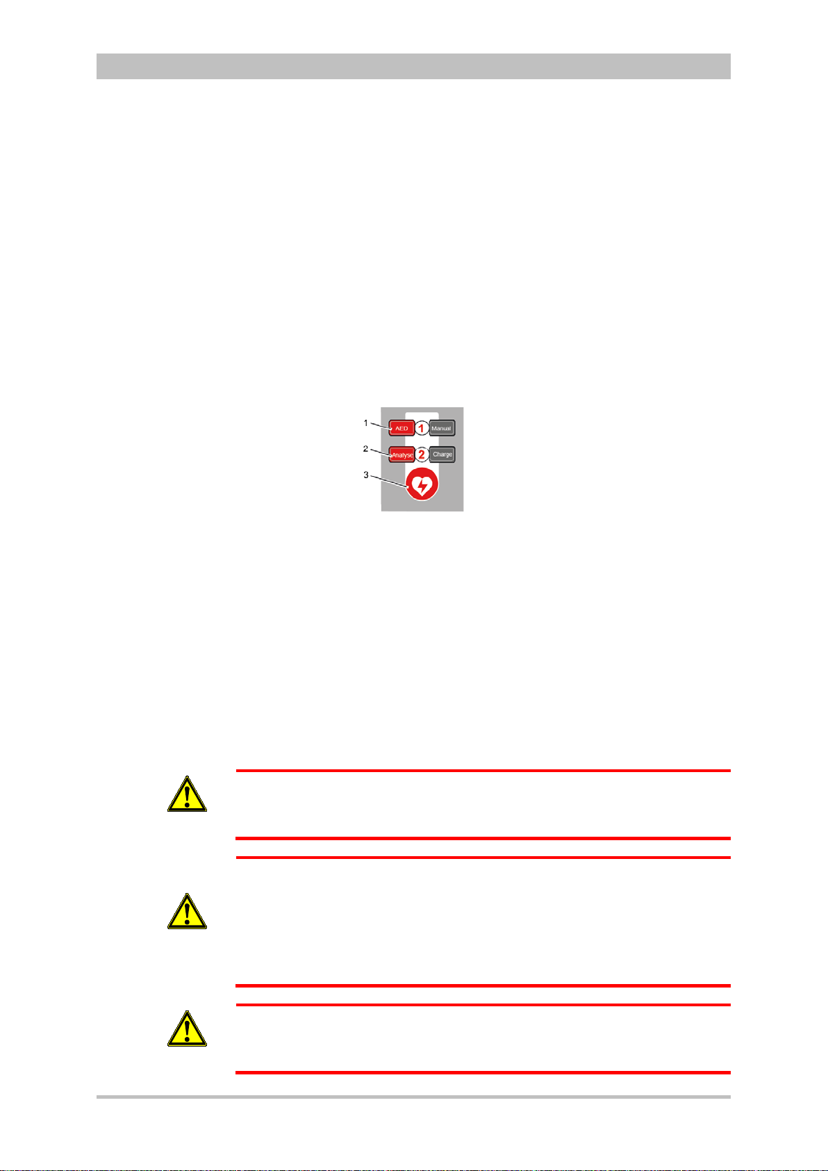
User Manual corpuls
Audio recording
3
Operation – Therapy
The curve field in the first line of the screen is pre-set and cannot be configured.
The first curve field displays the ECG recorded by the respective defibrillation
electrodes, switching automatically between IIauto and DEauto:
• corPatch electrodes: - DEauto recording, via the corPatch electrodes
• shock paddles: - Einthoven lead IIauto,
recorded via ECG electrodes and 4-pole ECG
monitoring cable
or
- DEauto recording,
via shock paddles, if no 4-pole ECG
monitoring cable is connected
The value of ECG amplitude is set to 10 mm/mV. Automatic ECG amplitude
control is disabled.
The following keys are available to operate the device in AED mode:
1. AED
2. Analyse
3. Shock
WARNING
WARNING
Fig. 5-4 AE D mode function keys
When using corPatch electrodes, the shock is released by pressing the Shock
key at the monitoring unit.
When using the shock paddles, the shock is released by pressing both buttons
at the shock paddles.
The charged defibrillator can be discharged internally by pressing the softkey
[Cancel].
In AED mode, a configurable audio recording option is available which is
disabled by default. If the audio recording option is enabled by the person
responsible for the device, all surrounding noises are recorded (see
chapter 7.4.3 Configuration of the Defibrillation Function (Persons Responsible
for the Device) , page 163).
In each individual case the trained user determines the progress of treatment
according to medical requirements. The procedure shown here reflects the
operating possibilities of the device.
In patients with an implanted pacer placing the therapy electrodes directly
above the pacer unit is contraindicated.
Under certain conditions irreversible damage to the myocardium might be
caused by the invasive pacer electrode.
In such a case, choose the reversed position of the therapy electrodes: below
the left clavicula parasternally and below the right mamilla, approx. 5th
intercostal space at the level of the apex of the heart.
ENG - Version 2.1 – P/N 04130.2 69
WARNING
In patients with an implanted pacer, it is possible that shockable ECG rhythms
or arrhythmias will only be detected to a limited extent.
Page 82

Operation – Therapy
corPatch
AED
Analyse
An
aly
se
Performing a
User Manual corpuls
3
WARNING
WARNING
WARNING
WARNING
defibrillation
If the network configuration of the corpuls
in AED mode (change from a wireless radio connection to a mechanical
3
is modified during ECG analysis
connection or vice versa), the ECG analysis will be interrupted.
The ECG analysis must be restarted in this case.
Equipment which is not defibrillation proof must be disconnected from
patients during defibrillation.
When a defibrillation is performed, all necessary ECG cables have to be
connected to the patient box at all times and all electrodes have to be
attached to the patient. If the 4-pole ECG monitoring cable and the
complementary 6-pole diagnostic cable are not used in a defibrillation, they
have to be disconnected from the patient box.
In defibrillation mode, no physiological alarms are indicated or saved.
Technical alarms are signalled acoustically and visually.
5.3.2 Defibrillation in AED mode with
Electrodes
When using corPatch electrodes, the ECG is obtained and the analysis is
performed via the corPatch electrodes attached to the patient (indicated as
DE). An additional 4-pole ECG monitoring cable is not needed.
1. To start the AED mode, press the AED key.
2. Prepare the patient (see chapter 5.2 Preparing the Patient for Defibrillation,
Cardioversion and Pacer Therapy, page 67).
3. Check the electrode package for damage and check the expiry date.
4. Attach corPatch electrodes to the patient, as shown on the electrode
package.
5. If enabled, select the required energy level via the softkeys or the jog dial
(see chapter 7.4.3 Configuration of the Defibrillation Function (Persons
Responsible for the Device) , page 163).
6. To start the ECG analysis, press the Analyse key.
7. With the message "Deliver shock" and the ready-signal, the device
indicates that the defibrillation can be performed.
8. To perform defibrillation, keep the Shock key depressed until the shock
has been delivered.
9. If the shock has been released successfully, the message Shock
performed is shown.
10. The message Shock not recommended indicates that the defibrillation
cannot be performed and that the Shock key is locked.
11. Continue with the standardised or locally valid resuscitation protocol.
12. The message Start analysis indicates that the Analyse key should be
pressed again to perform an ECG analysis.
70 ENG - Version 2.1 – P/N 04130.2
Page 83

User Manual corpuls
AED
Note
Note
Analyse
Note
WARNING
3
Operation – Therapy
With the introduction of the corPatch easy pre-connected therapy electrodes
(P/N 05120.1), for adults (P/N 04324.3) and Pediatric (P/N 05120.1) the higher
limits for the body weight of patients have been set. The manufacturer assures
that also the previously supplied therapy electrodes corPatch easy Neonate
(P/N 04324.2) can be used for defibrillations with an energy level of up to
100 Joule maximum and up to a body weight of 25 kg. The operational safety
as well as medical effectiveness of the therapy electrodes is guaranteed.
The CPR rhythm can be supported acoustically by activating the metronome via
the softkey [Metronome].
The selected energy level is available for 30 seconds after charging. If no shock
is triggered within this time span, the device discharges itself internally.
During ECG analysis, it is essential to avoid external commotion and
vibration. Keep the patient lying down calmly.
Do not touch the patient.
It is essential to discontinue artificial respiration during ECG analysis. This
leads to false analysis results since the periodic expansion of the chest may
simulate an ECG rhythm.
5.3.3 Defibrillation in AED Mode with Shock Paddles
To perform a defibrillation in AED mode with shock paddles, an ECG must be
obtained for analysis via the ECG electrodes and the 4-pole ECG monitoring
cable.
To start the AED mode, press the AED key.
1. Prepare the patient (see chapter 5.2 Preparing the Patient for Defibrillation,
Cardioversion and Pacer Therapy, page 67).
2. Place all four ECG electrodes of the 4-pole ECG monitoring cable on the
patient (see chapter 6.2 ECG Monitoring, pag e 95).
3. Completely wet the electrode surfaces of the shock paddles with
defibrillation electrode gel.
4. If enabled, select the required energy level via the softkeys or the jog dial
(see chapter 7.4.3 Configuration of the Defibrillation Function (Persons
Responsible for the Device) , page 163).
5. To start the ECG analysis, press the Analyse key or one of the buttons at
the shock paddles.
6. With the message Deliver shock and the ready-signal, the device
indicates that the defibr ill ati on can be perf ormed.
ENG - Version 2.1 – P/N 04130.2 71
Page 84

Operation – Therapy
1
2
Performing a
An
aly
se
Note
Note
Note
Note
Note
defibrillation
User Manual corpuls
7. Place the APEX shock paddle (Fig. 5-5, item 1) on the lower left of the
thorax beside apex of the heart (5th ICS).
8. Place the STERNUM shock paddle (Fig. 5-5, item 2) to the right of the
sternum.
Fig. 5-5 Applying the shock paddles
1 Position of the APEX shock paddle
2 Position of the STERNUM shock paddle
9. Hold down both shock paddle buttons until a shock has been released. By
pressing the buttons a confirmative tone sounds.
10. If the shock has been released successfully, the message Shock
performed is shown.
11. The message Shock not recommended indicates that the defibrillation
cannot be performed and that the buttons at the shock paddles are locked.
12. Continue with the standardised or locally valid resuscitation protocol.
13. To start the ECG analysis, press the Analyse key or one of the buttons at
the shock paddles again.
The CPR rhythm can be supported acoustically by activating the metronome via
the softkey [Metronome].
The selected energy level is available for 30 seconds after charging. If no shock
is triggered within this time span, the device discharges itself internally.
For safety reasons, when using shock paddles, the keys Charge and Shock on
the monitoring unit are blocked. The charging and release of the defibrillation
shock can only be triggered via the shock paddle buttons.
To pause the charging process, simultaneously press both shock paddle
buttons briefly. To continue the charging process, briefly press one of the shock
paddle buttons.
Energy selection can be performed by connecting both electrode surfaces of the
shock paddles (short-circuiting). To decrease the energy, briefly press the
APEX shock paddle button. To increase the energy, briefly press the
STERNUM shock paddle button.
3
72 ENG - Version 2.1 – P/N 04130.2
Page 85

User Manual corpuls
WARNING
WARNING
3
Operation – Therapy
During ECG analysis, it is essential to avoid external commotion and
vibration. Keep the patient lying down calmly.
Do not touch the patient.
It is essential to discontinue artificial respiration during ECG analysis. This
leads to false analysis results since the periodic expansion of the chest may
simulate an ECG rhythm.
Make sure that no defibrillation electrode gel gets into the insulation area
between the electrode surface and the handle. Only use defibrillation
electrode gel intended for this purpose.
ENG - Version 2.1 – P/N 04130.2 73
Page 86
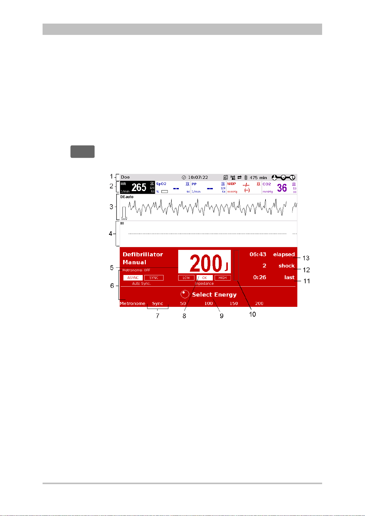
Operation – Therapy
Manuell
Manual
User Manual corpuls
5.4 Manual Defibrillation and Cardioversion
5.4.1 Information on Manual Defibrillation and Cardioversion
In the manual defibrillation mode of corpuls
action and decision-making concerning operation of the defibrillator. They have
to assess the ECG and can, depending on the patient, select the necessary
energy and trigger the defibrillation- or cardioversion shock.
3
The boot-up time of the corpuls
is reduced if the corpuls3 is switched on
directly in manual defibrillation mode by pressing the Manual key.
After pressing the Manual key the following screen structure appears:
3
, the users have full freedom of
3
Fig. 5-6 Manual defibrillation, initial screen (illustration may differ)
1 Status line
2 Parameter area
3 Current ECG (recording II/DEauto)
4 Configurable curve area
5 Pre-set energy
6 Metronome
7 Synchronisation option
8 Patient impedance
9 Operating instruction
10 Charging status
11 Time since last shock
11 Number of shocks since switching on the device
13 Time since defibrillation mode was launched
74 ENG - Version 2.1 – P/N 04130.2
Page 87

User Manual corpuls
3
Operation – Therapy
The curve field in the first line of the screen is pre-set and cannot be configured.
There, the ECG recorded by the respective therapy electrodes is displayed,
switching automatically between IIauto and DEauto:
• corPatch electrodes: - DEauto recording, via the corPatch electrodes
& shock spoons
• shock paddles: - Einthoven lead IIauto,
recorded via ECG electrodes and 4 pole ECG
monitoring cable
or
- DEauto recording,
via shock paddles, if no 4 pole ECG
monitoring cable is connected
Amplification of the ECG curves is 10 mm/mV. Automatic ECG amplitude
control is disabled.
Persons responsible for the device can pre-set the energy level with the
function Auto Energy. This energy level is automatically available when the
device is switched to manual defibrillation mode for the first time (see
chapter 7.2 Configuration of the Monitoring Functions, page 148).
The following keys are available to operate the device in manual mode:
1. Manual
2. Load
3. Shock
Fig. 5-7 Function keys for manual defibrillation and cardioversion
When using corPatch electrodes or shock spoons, the shock is released by
pressing the Shock key at the monitoring unit.
When using the shock paddles, the shock is released by pressing both buttons
at the shock paddles.
The charged defibrillator can be discharged internally by pressing the softkey
[Cancel].
Cardioversion settings are adjusted via the softkey [Sync].
The following settings are available:
• Auto Sync: If QRS complexes are detected, the device synchronises the
shock release for a cardioversion.
If no shock is triggered within one second after pressing and
holding the Shock key, the device performs automatically a
defibrillation.
• Sync: If QRS complexes are detected, the device synchronises the
shock release for a cardioversion.
If no QRS complexes are detected, a cardioversion or
defibrillation is not possible.
• Async The defibrillation is performed only asynchronously.
In this mode, a cardioversion is not possible.
ENG - Version 2.1 – P/N 04130.2 75
Page 88

Operation – Therapy
A cardioversion may lead to ventricular fibrillation or asystole. When
status.
corPatch
Manuell
Manual
Audio recording
WARNING
User Manual corpuls
In manual mode, a configurable audio recording option is available which is
disabled by default. If the audio recording option is enabled by the person
responsible for the device, all surrounding noises are recorded (see
chapter 7.4.3 Configuration of the Defibrillation Function (Persons Responsible
for the Device) , page 163).
performing a cardioversion, mind the following:
• The ECG has to be stable with a heart rate of at least 60/min.
• The synchronisation status has to remain constantly on SYNC.
• The QRS marks (triangles) have to mark each QRS complex.
• The shock release has to be effected according to valid guidelines.
• If the shock release does not take place one second after pressing
the buttons at the shock paddles or the Shock key at the monitoring
unit, the shock will be released independent of the synchronisation
3
Equipment which is not defibrillation proof must be disconnected from
patients during defibrillation and cardioversion.
WARNING
When a defibrillation is performed, all necessary ECG cables have to be
connected to the patient box at all times and all electrodes have to be
attached to the patient. If the 4-pole ECG monitoring cable and the
WARNING
complementary 6-pole diagnostic cable are not used in a defibrillation, they
have to be disconnected from the patient box.
No physiological alarm events are displayed and saved in defibrillation mode.
Technical alarms are indicated visually and acoustically.
WARNING
5.4.2 Manual Defibrillation with
When using corPatch electrodes, the ECG is obtained via the corPatch
electrodes attached to the patient (indicated as DE). Via additionally attached
ECG electrodes and the 4-pole ECG monitoring cable, further leads can be
displayed in the configurable second curve field (see chapter 6.2 ECG
Monitoring, page 95).
1. To start the manual defibrillation mode, press the Manual key.
2. Prepare the patient (see chapter 5.2 Preparing the Patient for Defibrillation,
Cardioversion and Pacer Therapy, page 67).
3. Check the electrode package for damage and check the expiry date.
4. Attach corPatch electrodes to the patient, as shown on the electrode
package. Select the required energy level with the jog dial or via the
softkeys and confirm by pressing the jog dial.
Electrodes
76 ENG - Version 2.1 – P/N 04130.2
Page 89

User Manual corpuls
L
a
den
C
h
a
rge
Note
Note
Note
Manuell
Manual
Note
Note
3
Operation – Therapy
5. To start the charging process, press the Charge key.
The charging process takes a maximum of 5 seconds depending on the
selected energy setting.
6. Wait until the message Ready for shock is displayed on the screen and
the ready-signal is sounding. The device is ready for releasing a
defibrillation shock.
7. Keep the Shock key depressed until the shock is delivered to perform
defibrillation or cardioversion.
8. If the shock has been released successfully, the message Shock
performed is shown.
9. Continue with the standardised or locally valid resuscitation protocol.
With the introduction of the corPatch easy pre-connected therapy electrodes
(P/N 05120.1), for adults (P/N 04324.3) and Pediatric (P/N 05120.1) the higher
limits for the body weight of patients have been set. The manufacturer assures
that also the previously supplied therapy electrodes corPatch easy Neonate
(P/N 04324.2) can be used for defibrillations with an energy level of up to
100 Joule maximum and up to a body weight of 25 kg. The operational safety
as well as medical effectiveness of the therapy electrodes is guaranteed.
The CPR rhythm can be supported acoustically by activating the metronome via
the softkey [Metronome].
If the jog dial is pressed in manual defibrillation mode, the energy selection at
the monitoring unit is only possible via the softkeys. Press the Manual key
again, to be able to select the energy level with the jog dial.
The selected energy level is available for 30 seconds after charging. If no shock
is triggered within this time span, the device discharges itself internally.
5.4.3 Manual Defibrillation and Cardioversion with Shock Paddles
When using shock paddles, the ECG is obtained via the shock paddles pressed
to the patient's thorax (indicated as DE). Via additionally attached ECG
electrodes and the 4-pole ECG monitoring cable, further leads can be displayed
in the configurable second curve field (see chapter 6.2 ECG Monitoring,
page 95).
Obtaining the ECG via the ECG electrodes and the 4-pole ECG monitoring
cable (as explained in the following) assures a better signal quality than via the
shock paddles.
1. To start the manual defibrillation mode, press the Manual key.
2. Prepare the patient (see chapter 5.2 Preparing the Patient for Defibrillation,
Cardioversion and Pacer Therapy, page 67).
3. Place all four ECG electrodes of the 4-pole ECG monitoring cable on the
patient (see chapter 6.2 ECG Monitoring, pag e 95).
4. Completely wet the electrode surfaces of the shock paddles with
defibrillation electrode gel.
ENG - Version 2.1 – P/N 04130.2 77
Page 90
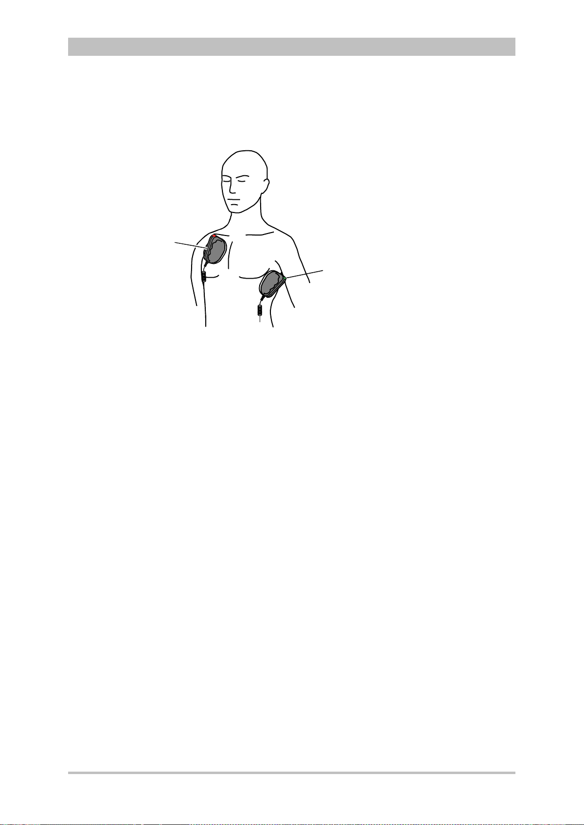
1
2
Performing a
defibrillation/
cardioversion
Note
Note
Note
Note
Energy selection
via the shock
paddle buttons
Operation – Therapy
User Manual corpuls
3
5. Place the APEX shock paddle (Fig. 5-8, item 1) on the lower left of the
thorax beside apex of the heart (5th ICS).
6. Place the STERNUM shock paddle (Fig. 5-8, item 2) to the right of the
sternum.
Fig. 5-8 Applying the shock paddles
1 Position of the APEX shock paddle
2 Position of the STERNUM shock paddle
7. Select the required energy level with the jog dial or via the softkeys.
8. To start the charging proc e s s, brief l y press one of the shock paddle buttons .
The charging process takes a maximum of 5 seconds depending on the
selected energy setting.
9. Wait until the message Ready for shock is displayed on the screen and
the ready-signal is sounding. The device is ready for releasing a
defibrillation shock.
10. Keep both shock paddle buttons depressed and hold until a shock has
been released. By pressing the buttons a confirmative tone sounds.
11. If the shock has been released successfully, the message Shock
performed is shown.
12. Continue with the standardised or locally valid resuscitation protocol.
By short circuiting the shock paddles the energy selection via the shock paddle
buttons is enabled. This function enables the energy selection with the jog dial
in 5 J increments. With the baby shock electrodes attached, this energy
selection is not possible.
The CPR rhythm can be supported acoustically by activating the metronome via
the softkey [Metronome].
If the jog dial is pressed in manual defibrillation mode, the jog dial is blocked
and the energy selection at the monitoring un it is onl y possibl e via the sof tkeys.
Press the Manual key again, to be able to select the energy level with the jog
dial.
The selected energy level is available for 30 seconds after charging. If no shock
is triggered within this time span, the device discharges itself internally.
For safety reasons, when using shock paddles, the keys Charge and Shock on
the monitoring unit are blocked. The charging and release of the defibrillation
shock can only be triggered via the shock paddle buttons.
78 ENG - Version 2.1 – P/N 04130.2
Page 91
User Manual corpuls
Note
Note
M
anuell
Manua
l
LadenCharge
Note
Note
Note
WARNING
WARNING
3
Operation – Therapy
The charging process can be interrupted by pressing simultaneous l y both shock
paddle buttons briefly. Pressing one of the shock paddle buttons again,
continues the charging process.
Energy selection can be performed by connecting both electrode surfaces of the
shock paddles (short-circuiting). To decrease the energy, briefly press the
APEX shock paddle button. To increase the energy, briefly press the
STERNUM shock paddle button.
Make sure that no defibrillation electrode gel gets into the insulation area
between the electrode surface and the handle.
Only use defibrillation electrode gel intended for this purpose.
Press the shock paddles firmly onto the patient’s thorax when the shock is
triggered (approx. 8 kg contact pressure for adults).
Keep both shock paddle buttons depressed until the shock is delivered
5.4.4 Manual Defibrillation and Cardioversion with Shock Spoons
Before using the shock spoons, please read and understand the safety and
WARNING
ENG - Version 2.1 – P/N 04130.2 79
preparation notices in the manual (P/N 04137.02).
When using shock spoons, the ECG is obtained via the shock spoons pressed
to the patient's heart. It is, however, recommended to obtain the ECG via the 4pole ECG monitoring cable (see chapter 6.2 ECG Monitoring, page 95).
Obtaining the ECG via the ECG electrodes and the 4-pole ECG monitoring
cable (as explained in the following) assures a better signal quality than via the
shock paddles.
When using shock spoons, the energy available is limited by the device to a
maximum of 50 J.
1. To start the manual defibrillation mode, press the Manual key.
2. Place all four ECG electrodes of the 4-pole ECG monitoring cable on the
patient (see chapter 6.2 ECG Monitoring, pag e 95).
3. Screw sterile shock spoons of the correct size into the sterile shock spoon
holders.
4. Select the required energy level with the jog dial or via the softkeys and
confirm by pressing the jog dial.
5. To start the charging process, press the Charge key.
The charging process takes a maximum of 5 seconds depending on the
selected energy setting.
Page 92

Operation – Therapy
1 2 2 1
3 3
Note
Note
Defibrillation
electrodes
Connecting baby
shock electrodes
corPatch easy
electrodes
Neonates
WARNING
User Manual corpuls
6. Wait until the message Ready for shock is displayed on the screen and
the ready-signal is sounding. The device is ready for releasing a
defibrillation shock.
7. Keep the Shock key depressed until the shock is delivered to perform
defibrillation or cardioversion.
8. Continue with the standardised or locally valid resuscitation protocol.
If the jog dial is pressed in manual defibrillation mode, the energy selection at
the monitoring unit is only possible via the softkeys. Press the Manual key
again, to be able to select the energy level with the jog dial.
The selected energy level is available for 30 seconds after charging. If no shock
is triggered within this time span, the device discharges itself internally.
5.4.5 Manual Defibrillation and Cardioversion of Neonates and Children
With the baby shock electrodes the defibrillation energy is automatically
reduced. The energy reduction is effected at a ratio of 1:10, i.e. one tenth of
the energy set in defibrillation mode
If, for example, an energy level of 200 J is selected, the shock is released
with an energy of just 20 J.
3
For the defibrillation and cardioversion of neonates and children, various types
of defibrillation electrodes are available:
• Baby shock electrodes (as adapters for shock paddles, up to 5 kg body
weight maximum)
• corPatch easy electrodes Neonates up to 12 kg body weight maximum
• corPatch easy electrodes Pediatric up to 25 kg body weight maximum
• corPatch easy electrodes for adults from 10 kg or 20 kg body weight
• corPatch easy electrodes pre-connected from 20 kg body weight
When using corPatch easy electrodes Neonates and Pediatric, the energy
available is limited by the device to a maximum of 100 J.
1. Please read and follow the instructions and warnings on the inner surface
of the baby shock electrodes.
80 ENG - Version 2.1 – P/N 04130.2
Fig. 5-9 Connecting baby shock electrodes
1 Shock paddles for adults
2 Baby shock electrodes
3 Diode for functional test
Page 93
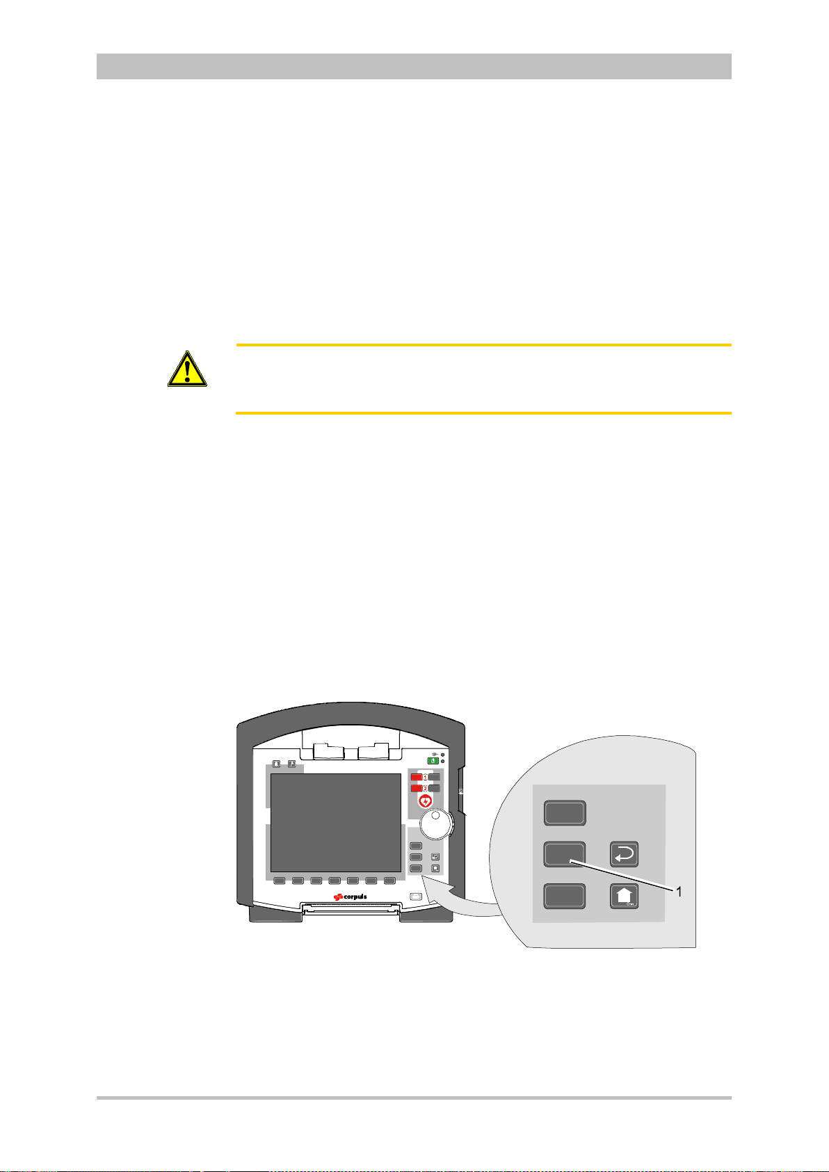
User Manual corpuls
Einsatz
Monitor
Pacer
AED
Analyse Lade
n
Manuell
Einsatz
Monitor
Pacer
Applying the
corPatch
electrodes
Note
Note
Caution
3
Operation – Therapy
2. Fit the baby shock electrodes (item 2) onto the shock paddles (item 1) and
press until the curved edge engages perceptibly.
3. Perform a functional test:
Trigger a 10 J shock with short-circuited baby shock electrodes.
The two diodes (item 3) light up. If the diodes do not light up, check the
connections and repeat the functional test.
4. Further procedure as described in chapter 5.4.3 Manual Defibrillation and
Cardioversion with Shock Paddles, page 77.
If the shock is aborted while using baby shock electrodes, the message Shock
performed might be shown.
Short-circuit the baby shock electrodes away from your body during the
functional test.
5.5 External Pacer
5.5.1 Information on the External Pacer
By electrical stimulation of the heart muscle, the external pacer of corpuls
can supplement or positively influence or completely take over its function.
The pacer emits pacing pulses to the patient’s heart muscle via the corPatch
electrodes attached to the thorax. The corPatch electrodes are placed in the
anterior and posterior position in this case.
Different operating modes enable the user to adapt the treatment individually for
each patient.
By pressing the Pacer key the device activates the pacer mode:
3
ENG - Version 2.1 – P/N 04130.2 81
Fig. 5-10 Pacer function
1 Pacer key
For a reliable suppression of pacer impulses, the 4-pole ECG monitoring cable
has to be used.
Page 94
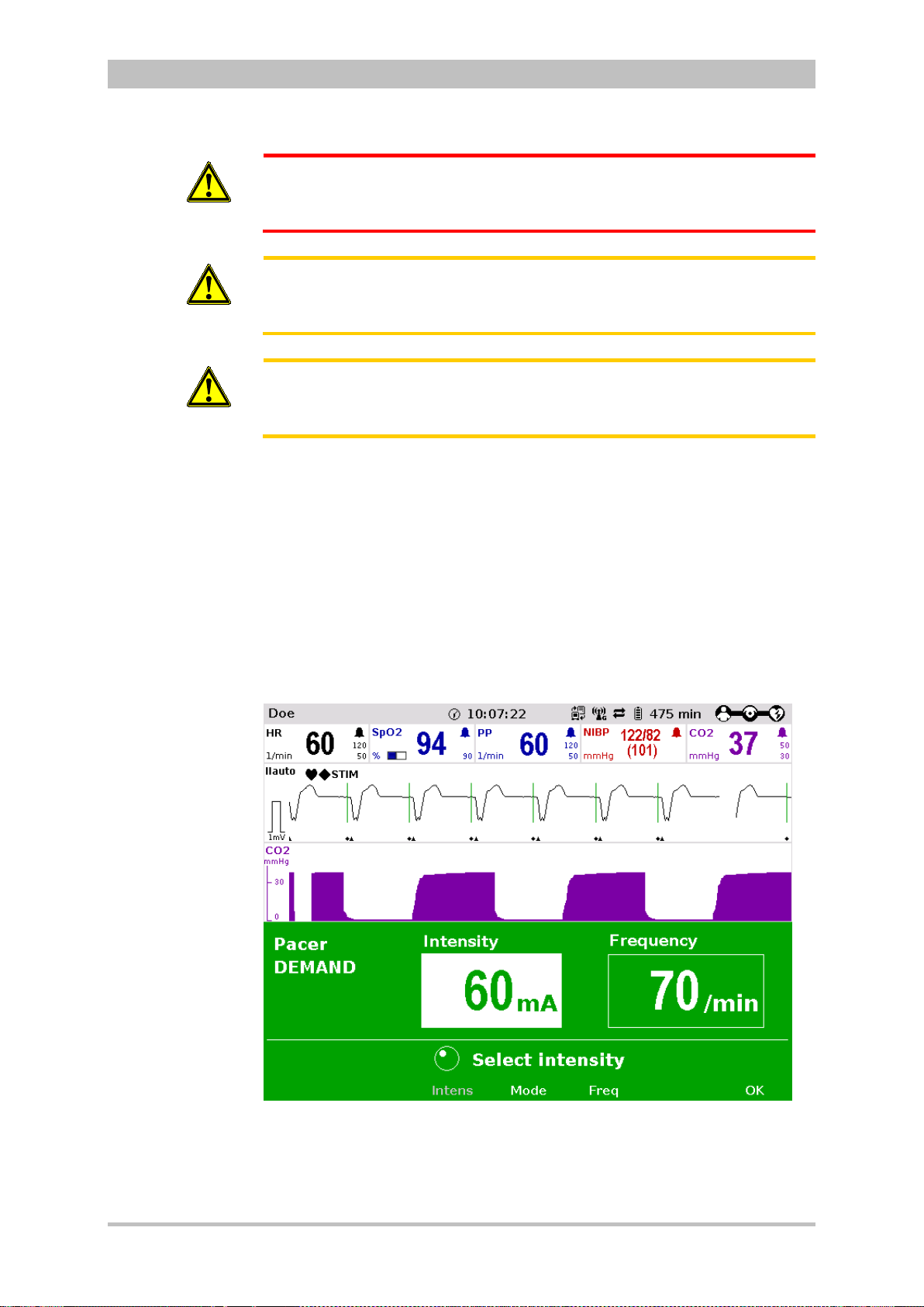
Operation – Therapy
Pacer pulse
identification
Note
WARNING
Caution
Caution
User Manual corpuls
In patients with an implanted pacer, it is possible that shockable ECG rhythms
or arrhythmias will only be detected to a limited extent.
Do not operate the external pacer of the device near high frequency surgical
devices.
This may result in signal interference with the pacer.
The patient must not remain unattended when using the external pacer
The basic settings when using the device in pacer mode for the first time are:
• Intensity: 0 mA
• Frequency: 70/min
• Operating mode: DEMAND
The moment of stimulation is marked by a green vertical line (spike) in the ECG
curves. A small lozenge symbol is located under each spike. In addition, a large
lozenge symbol is flashing in the upper left corner of the curve field.
The lozenge symbol in the upper left corner indicates the stimulation impulse
of an implanted pacer.
3
82 ENG - Version 2.1 – P/N 04130.2
Fig. 5-11 Pacer pulse identification
Connecting and disconnecting ECG electrodes may simulate false-positive
pacer pulses. If this occurs, the device briefly detects pacer pulses, although the
patient does not have an implanted (inter n al) pac er.
Page 95

User Manual corpuls
FIX Operating
mode
Note
"STIM" message
Note
3
Operation – Therapy
Pacer operation is indicated by the message “STIM” in the upper left corner of
the curve field.
When stimulation is performed, the message “STIM” is flashing. When “STIM” is
permanently displayed, the pacer is switched on (e.g. in DEMAND mode in a
frequency range in which no stimulation is necessary), but is not active (no
stimulation). Only when the pacer is switched off or paused, the message
“STIM” is not displayed.
The pacer continues to operate in monitoring mode.
If the user
• presses the On/Off k ey or
• switches to defibrillation mode
while the pacer is running, a confirmation prompt appears, warning that the
pacer is active. Switching off the pacer or switching to defibrillation mode can be
confirmed by pressing the softkey [OK] or aborted by pressing the softkey
[Cancel].
3
As long as the pacer is active, the corpuls
cannot be switched off or switch to
defibrillator mode without a prior confirmation prompt.
The pacer can only be operated when corPatch electrodes are connected to
the therapy master cable. The pacer is switched off automatically if a cable is
removed while running in pacer mode.
WARNING
5.5.2 Preparing the pacer function
In FIX operating mode, pacing is performed with a fixed frequency, regardless
of the patient’s own heart rate.
The pacer function and the ECG recording function are compromised if
adhesion of the corPatch electrodes or ECG electrodes is impaired due to
contaminated skin or excessive hair.
Only use corPatch electrodes indicated in the list of approved accessories.
The corPatch electrodes must no longer be used after the expiry date
indicated on the packaging has passed.
1. Prepare the patient (see chapter 5.2 Preparing the Patient for Defibrillation,
Cardioversion and Pacer Therapy, page 67).
2. If necessary, prepare ECG monitoring (see chapter 6.2.3 Pre pari ng ECG
Monitoring, page 97).
ENG - Version 2.1 – P/N 04130.2 83
Page 96

Operation – Therapy
2
1
DEMAND mode
Note
OVERDRIVE
nction
User Manual corpuls
3. Place the blue-labelled corPatch electr ode on the ba ck beside vertebral
column beneath the shoulder blade (item 1).
4. Place the red-labelled corPatch electrode on the thorax at the level of the
bottom third of the sternum (between 4th and 5th ICS) (item 2).
5. Connect the corPatch electrodes to the therapy master cable.
3
Fig. 5-12 Pacer , attac h ing the elec tr o des
1 Position of the blue-labelled corPatch electrode (posterior)
2 Position of the red-labelled corPatch electrode (anterior)
In DEMAND operating mode, pacing is only performed when the patient’s own
heart rate is below the pre-set pacing frequency.
In addition to the corPatch electrodes, the ECG has to be obtained via ECG
electrodes and the 4-pole ECG monitoring cable in DEMAND mode.
With the OVERDRIVE function, a patient with a high-frequency cardiac rhythm
fu
is restored to a normal-frequency cardiac rhythm
84 ENG - Version 2.1 – P/N 04130.2
Page 97

User Manual corpuls
FIX or DEMAND
operating mode
Note
Preparing the
device
Pacer
Note
3
5.5.3 Starting the Pacer Function
Prerequisite: Device is switched on.
1. Press the Pacer key to run the pacer function.
The following screen structure appears:
Operation – Therapy
Fig. 5-13 Pacer, initial screen
1 Heart rate parameter field
2 Current ECG (recording II/DEauto)
3 Configurable curve field
4 Pacer operating mode
5 Selected intensity
6 Softkey assignment
7 Operating instruction
8 Selected frequency
The pacer always starts in DEMAND operating mode.
2. Press the softkey [Mode], if the operating mode FIX is to be used. If
DEMAND operating mode is to be used, continue with step 4.
3. Press the softkey [FIX] to select FIX operating mode.
4. Press the softkey [Freq.] and select the required frequency with the jog dial.
The pacing frequency can be adjusted in 5/min increments within the range of
30/min to 150/min.
ENG - Version 2.1 – P/N 04130.2 85
WARNING
Pacing begins automatically as soon as an intensity of more than 0 mA is
selected.
5. Press the softkey [Intens] and select the required intensity with the jog dial.
Page 98
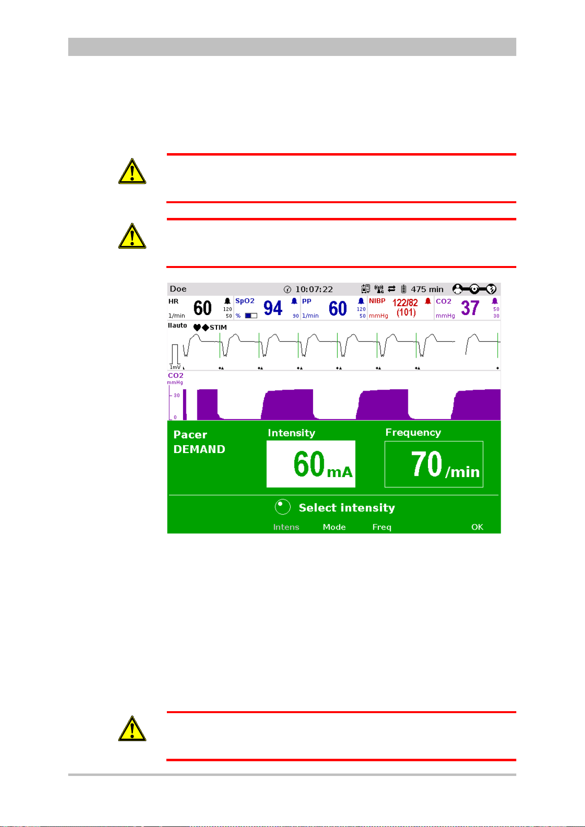
Operation – Therapy
Note
Pause pacing?
Continuing
pacing
Ending pacing
WARNING
WARNING
User Manual corpuls
The pacing intensity can be adjusted in 5 mA increments within the range of
0 to 150 mA.
Regularly check effectiveness of the pacer by checking the central pulse.
In patients with an implanted pacer, it is possible that shockable ECG rhythms
or arrhythmias will only be detected to a limited extent.
3
86 ENG - Version 2.1 – P/N 04130.2
WARNING
Fig. 5-14 Pacer, selecting the intensity
If necessary, press the softkey [Pause] to interrupt pacing. Answer the
confirmation prompt Pause pacing? with the softkey [Yes].
If pacing has been paused, press the softkey [Continue pacing] to continue
pacing. Answer the confirmation prompt Continue pacing? with the softkey
[Yes].
To end the current pacing, press the softkey [Off]. Answer the confirmation
prompt Switch off pacer? with the softkey [Yes] to end pacing and to reset
the pacer (DEMAND, 0 mA, 70/min).
The procedure described below is a recommendation from the manufacturer.
Qualified users will determine the progress of treatment on their own account.
Page 99

User Manual corpuls
OVERDRIVE
function
Pause pacing?
Continuing
pacing
Ending pacing
3
Operation – Therapy
1. Press the Pacer key to run the pacer function.
2. Press the softkey [Mode] to leave the operating mode DEMAND.
3. Press the softkey [OVR] to select the OVERDRIVE function. The pacing
frequency will be automatically adjusted to a value just below the patient’s
frequency.
4. Press the softkey [Intens] and select an intensity value between 60 and
100 mA.
Fig. 5-15 Pacer, OVERDRIVE function
5. Press the softkey [Freq] and gradually increase the frequency until the
pacer stimulates regularly. Pacing only starts when the patient’s heart rate
is exceeded.
6. If the pacing pulses are not followed by a contraction of the heart muscle,
press the softkey [Intens] and increase the intensity until the stimulation
threshold is reached and the heart rate permanently follows the pacing
frequency.
7. Press the softkey [Freq] and decrease the frequency until the required
heart rate is achieved.
8. If necessary, repeat step 6 and 7.
If necessary, press the softkey [Pause] to interrupt pacing. Answer the
confirmation prompt Pause pacing? with the softkey [Yes].
If pacing has been paused, press the softkey [Continue pacing] to continue
pacing. Answer the confirmation prompt Continue pacing? with the softkey
[Yes].
To end the current pacing, press the softkey [Off]. Answer the confirmation
prompt Switch off pacer? with the softkey [Yes] to end pacing and to reset
the pacer (DEMAND, 0 mA, 70/min).
ENG - Version 2.1 – P/N 04130.2 87
Page 100
Operation – Therapy
Note
Note
WARNING
WARNING
WARNING
User Manual corpuls
Regularly check effectiveness of the pacer by checking the central pulse.
If the defibrillator/pacer battery enters a low state of charge in pacer mode
while the modules are being operated separately from one another, a alarm
message “Battery low (Defib)“ appears on the screen.
If the defibrillator/pacer battery is almost completely discharged and the
defibrillator/pacer will soon switch off, the alarm message “Check pacer”
appears.
In both cases, immediately connect the modules mechanically or connect the
defibrillator/pacer to a mains power supply.
If the monitoring unit loses the network connection in pacer mode due to the
defibrillator/pacer being out of range, this will be indicated visually and
acoustically on the screen and by the alarm message “Check pacer”. Pacing
will be continued, but pacer alarms and errors cannot be displayed. In this
case, the modules must be brought immediately within an adequate range or
reconnected mechanically.
3
WARNING
All four ECG electrodes of the 4-pole ECG monitoring cable must be
connected to the patient.
If the electrodes of the complementary 6-pole ECG diagnostic cable are to be
used additionally, all six electrodes must be connected to the patient and the
connector must be plugged into the patient box. No electrode must be left
unattached.
For safety reasons, if a defibrillation is performed with shock paddles, it is not
permitted that the complementary 6-pole ECG diagnostic cable is preconnected to the patient box and none of the electrodes are attached.
To avoid unintentional switching off of the defibrillator/pacer, the On/Off key has
to be held down for at least 3 seconds for switching off.
If the battery on the monitoring unit is replaced during pacer operation, the
pacer has to be called up again.
88 ENG - Version 2.1 – P/N 04130.2
 Loading...