

Page 1

Document name
and location:
S:\Reparaturen\STK_Protokolle\STK_c³_with_test_instruction
_EN.docx
Release
identification:
Software version 2.1.0
Creation date:
2013-05-07
Release date:
2013-05-15
Originator name:
Carsten Fuchs
Release name:
Udo Franke
corpuls
³
Safety Technical Test, Test instruction and test report 1/16
Warning
Implementation of Safety Technical Tests implies the occurrence of high voltages
which may result in severe injuries or death. Only authorized qualified personnel are
permitted to carry out Safety Technical Tests.
Attention
Safety Technical Tests should only be carried out by authorized personnel with
calibrated measuring equipment and simulators.
Description
Manufacturer or supplier
Model
Part no.
Safety analyzer to perform protective earthing-, device leakage
current-, isolation resistance
measurement and high voltage test
EKU Elektronik GmbH,
D-56291 Leiningen
MTP 6000 (or comparable)
Defibrillator/Pacer analyzer
Fluke Biomedical Division,
Everett, WA 98203, U.S.
Impulse 7000 (or comparable)
Multi parameter/ECG simulator
Fluke Biomedical Division
PS420 (or comparable)
Digital multimeter
Fluke Corporation
Series 80V (or comparable)
Digital fine manometer
GREISINGER electronic GmbH,
D-93128 Regenstauf
GMH 3160-07 (or comparable)
Mains charger with magnetic plug,
12 volts DC / 9 amp.
GS Elektromedizinische Geräte
G. Stemple GmbH,
D-86916 Kaufering
04501.120
Test cable set for Safety Technical
Test Patient Box corpuls³
W0029.14100
Test cable set for Safety Technical
Test Defibrillator Unit corpuls³
W0029.24100
Test cable for Safety Technical
Test Display Unit corpuls³ with LAN
W0029.34100
Paddle holder for leakage current
and H/V testing, corpuls³
W0029.031263
Paddle for leakage current and high
voltage testing corpuls³
(2 pcs. required)
W0029.04326
Test cable Safety Technical Test
Charger with magnetic plug
corpuls³
W0029.04501
Safety Technical Test
For legal requirements and periods of Safety Technical Tests see chapter 9.4.1 of
Operators Instruction.
Implementation of Safety Technical Tests is only accepted when carried out according to
both, this test instruction and the Operators Instruction, and at least documented
according to this test report.
Test equipment, adapters and facilities
Page 2
Document name
and location:
S:\Reparaturen\STK_Protokolle\STK_c³_with_test_instruction
_EN.docx
Release
identification:
Software version 2.1.0
Creation date:
2013-05-07
Release date:
2013-05-15
Originator name:
Carsten Fuchs
Release name:
Udo Franke
corpuls
³
Safety Technical Test, Test instruction and test report 2/16
Adapter for leakage current test
Masimo Rainbow® Module
W4212.00002
T-connector cable
04325.09
1
Check of external mechanical intactness of the device
1.1
Check of mechanical intactness. The device must neither have form cracks
nor fractures. In case of damage, present the device to an authorized
national or local GS representative for repair. Swivel the complete device
about 30°. The mechanisms must neither be too rough-running nor
automatically tilting.
1.2
Check covers and fasteners for completeness.
1.3
Check of shock paddles intactness. The paddles must be free from form
cracks in their synthetic material; the helix cable, the electrode plates and
the safety electrodes must be free of any damage; rubber caps of the
buttons must be available and undamaged, labels must be available. The
connector must easily and surely be lockable with the therapy cable. The
electrode surfaces should be free of gel leftovers and other contamination.
1.4
Check of attached cables and sensors. Check cleading of cables and
sensors for insulating damage; if necessary remove paste-on labels
installed by the operator. Continued use of broken cables and sensors is
forbidden.
1.5
Check printer assembly, lid and locking mechanism. The printer lid should
easily release and lock.
1.6
Check of labels, warning and safety instruction plates for completeness and
readability. Check of type plates for readability. Note the serial numbers of
each single component to be tested in the test report sheet.
1.7
Check interlocking mechanisms between the single components. Therefore
unlock and relock the components. The interlocking mechanism must be
free of damage.
1.8
Check the magnetic connector contact panels of the of the single
components for damage and pollution. Clean the panels if necessary.
1.9
Shaking test. Shake each of the single components to detect loose parts
inside.
Warning
Do not open the device! Inner parts may be under high voltage. Disregarding may
cause severe injuries or death! In case of defect contact your authorized national or
local GS representative for inspection and potential repair.
Test instruction for Safety Technical Test
Page 3
Document name
and location:
S:\Reparaturen\STK_Protokolle\STK_c³_with_test_instruction
_EN.docx
Release
identification:
Software version 2.1.0
Creation date:
2013-05-07
Release date:
2013-05-15
Originator name:
Carsten Fuchs
Release name:
Udo Franke
corpuls
³
Safety Technical Test, Test instruction and test report 3/16
2
Protection against electrical shock hazard
Attention
During following measurements, all single components must be separated from
electrical power supply (power supply pack). Take the batteries out of the single
components!
Attention
Performance of both the leakage current measuring of application parts (item 2.6)
and the high voltage test (item 2.7) requires the application of the specified GSspecific adapters and facilities. Using other adapters and facilities may result in
device damage and termination of warranty rights!
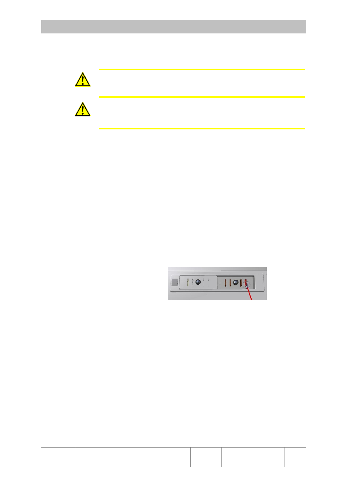
2.1
Check of protective earthing of the external power supply pack (IEC
62353:2007, item 5.3.2.2, image 1, protection class I). Connect the mains
plug to the safety tester and measure with the probe at the minus pole of
the corpuls magnet connector using the test cable P/N W0029.04501 to
activate the switch inside the male connector. Testing current must be not
less than 200 mA and must not exceed a limit of 10 A. This step must not
be done for power supplies with part number 04500.1202 and 04501.1201.
2.2
Measuring of device leakage current of external power supply pack (IEC
62353:2007, item 5.3.3.2.3, image 4, protection class I) (direct
measurement).
2.3
Measuring of insulation resistance of the external power supply pack (IEC
62353:2007, item 5.3.4, image 9). Testing voltage 500 V (DC).
2.4
Measuring of line resistance between potential equalization plug and minus
pins of power contact field of the Defibrillator Unit (by using a Hirschmann
clip or an alligator clip). Remove cover if required. Testing current must be
not less than 200 mA and must not exceed a limit of 10 A. The potential
equalization plug may be covert by a plastic cover.
2.5
Measuring of line resistance between safety electrodes of connected shock
paddles and potential equalization plug by using a resistance measuring
gauge. Testing current must not exceed a limit of 1 A.
2.6
Measuring of leakage current of application parts (IEC 62353:2007, item
5.3.3.3.1, image 6, protection class I). Application parts at which is not
currently measured, must be grounded (to the potential equalization plug of
the Defibrillator Unit or to minus contact of the corpuls magnet connector of
the Patient Box). Measure between:
2.6.1
High voltage output of therapy cable/therapy socket with connected
shock paddles and potential equalization plug (connect the shock
paddles to the therapy cable/therapy socket and put on the adapter
P/N w0029.031263).
2.6.2
High voltage output of therapy cable/therapy socket with connected
T-connector cable (P/N 04325.09) and potential equalization plug.
The measuring is only required if internal shock electrodes (shock
spoons) are applied.
2.6.3
High voltage output of test signal connector and potential
equalization plug.
Page 4

Document name
and location:
S:\Reparaturen\STK_Protokolle\STK_c³_with_test_instruction
_EN.docx
Release
identification:
Software version 2.1.0
Creation date:
2013-05-07
Release date:
2013-05-15
Originator name:
Carsten Fuchs
Release name:
Udo Franke
corpuls
³
Safety Technical Test, Test instruction and test report 4/16
2.6.4
Short-wired test contact pins of the paddle trays and potential
equalization plug (if the test contact pins were replaced by
accessory bags Part no. 04322.50 and 04322.51, the original
condition must be restored for the time of measurement).
2.6.5
ECG inputs (4-pole and 6-pole connected) and minus contact of the
corpuls magnet connector of the Patient Box.
2.6.6
SpO
2
input and minus contact of the corpuls magnet connector of
the Patient Box.
2.6.7
CO
2
input and minus contact of the corpuls magnet connector of the
Patient Box.
2.6.8
Input Temp1 and minus contact of the corpuls magnet connector of
the Patient Box.
2.6.9
Input Temp2 and minus contact of the corpuls magnet connector of
the Patient Box.
2.6.10
Input IBP1 and minus contact of the corpuls magnet connector of
the Patient Box.
2.6.11
Input IBP2 and minus contact of the corpuls magnet connector of
the Patient Box.
2.6.12
CPR input and minus contact of the corpuls magnet connector of
the Patient Box.
2.6.13
LAN connector and minus contact of the corpuls magnet connector
of the Display Unit.
2.7
High voltage test of application parts (IEC 60601-2-4:2002, item 20, image
107). Application parts at which is not currently measured, must be
grounded (to the potential equalization plug of the Defibrillator Unit or to
minus contact of the corpuls magnet connector of the Patient Box). Set the
current limiter of the high voltage generator to 500 µA. No high voltage
flashover must appear; no release of the current limiter. Apply 5 kV (DC) for
30 sec each between:
2.7.1
High voltage output of therapy cable/therapy socket with connected
shock paddles and potential equalization plug (connect the shock
paddles to the therapy cable and put on the adapter P/N
w0029.031263).
2.7.2
High voltage output of test signal connector and potential
equalization plug.
2.7.3
Short-wired test contact pins of the paddle trays and potential
equalization plug (if the test contact pins were replaced by
accessory bags Part no. 04322.50 and 04322.51, the original
condition must be restored for the time of measurement).
2.7.4
ECG inputs (4-pole and 6-pole connected) and minus contact of the
corpuls magnet connector of the Patient Box.
2.7.5
SpO
2
input and minus contact of the corpuls magnet connector of
the Patient Box.
2.7.6
CO
2
input and minus contact of the corpuls magnet connector of the
Patient Box.
2.7.7
Input Temp1 and minus contact of the corpuls magnet connector of
the Patient Box.
2.7.8
Input Temp2 and minus contact of the corpuls magnet connector of
the Patient Box.
Page 5

Document name
and location:
S:\Reparaturen\STK_Protokolle\STK_c³_with_test_instruction
_EN.docx
Release
identification:
Software version 2.1.0
Creation date:
2013-05-07
Release date:
2013-05-15
Originator name:
Carsten Fuchs
Release name:
Udo Franke
corpuls
³
Safety Technical Test, Test instruction and test report 5/16
2.7.9
Input IBP1 and minus contact of the corpuls magnet connector of
the Patient Box.
2.7.10
Input IBP2 and minus contact of the corpuls magnet connector of
the Patient Box.
2.7.11
CPR input and minus contact of the corpuls magnet connector of
the Patient Box.
2.7.12
LAN connector and minus contact of the corpuls magnet connector
of the Display Unit.
3
General functions (charging, network connection)
For all following checks reinstall the batteries to the single components. The
single components will automatically switch on. Shutdown the single components
by operating the PWR on/off buttons and reassemble them to a compact device.
3.1
Switch on the compact device by operating the PWR button of the Display
Unit. Wait for boot-up (approx. 20 sec) then check network status.
3.2
Separate Defibrillator Unit, and then separate Patient Box from Display Unit
(modular mode). Check network status.
3.3
Check network status on the LCD of Patient Box.
3.4
Connect power supply pack to corpuls magnet connector of Defibrillator
Unit. Check charging control lamp of Defibrillator Unit.
3.5
Connect power supply pack to corpuls magnet connector of Patient Box.
Check charging control lamp of Patient Box.
3.6
Reassemble Patient Box with Display Unit (semi-modular mode). Check
charging control lamp of Display Unit.
3.7
Connect power supply pack to corpuls magnet connector of the Display
Unit. Check charging control lamp of Display Unit.
3.8
Reassemble all single components to a compact device; connect power
supply pack to corpuls magnet connector of Defibrillator Unit. Check
charging control lamp of Display Unit.
4
Device function Display Unit
For following tests operate the device in modular mode.
4.1
Check acoustics and keyboard of the Display Unit. Push every button of the
keyboard. The speaker must answer with a tone.
4.2
Check printer functionality. Select menu item “Test page“.
4.3
Check alarm and printer stop in case of lack of paper. Remove paper reel
and start printer operation.
4.4
Check visual alarm indication. In case of an alarm, the alarm lamp in the
jogdial must light up.
4.5
Check GSM function. Install SIM and establish a connection to a fax
recipient. Transmit a diagnosis ECG to the fax recipient.
4.6
Check the Health Insurance Card Reader. Insert an applicable card into the
card reader slot; patient’s data must appear on the screen.
4.7
Check the LAN function. Compare the MAC address of the device with the
papers of the device. Connect the device to a DHCP server. Dial the
assigned IP address of the device using the ping networking utility.
Page 6

Document name
and location:
S:\Reparaturen\STK_Protokolle\STK_c³_with_test_instruction
_EN.docx
Release
identification:
Software version 2.1.0
Creation date:
2013-05-07
Release date:
2013-05-15
Originator name:
Carsten Fuchs
Release name:
Udo Franke
corpuls
³
Safety Technical Test, Test instruction and test report 6/16
5
Device function Patient Box
For following tests operate the device in modular mode.
5.1
ECG Monitoring
5.1.1
Connect the 4-pole ECG cable to an ECG simulator and to the
Patient Box. Select a sinus waveform and call-up the function
„Resting ECG“ at the Display Unit. The derivations I, II, III, aVR,
aVL and aVF must appear.
5.1.2
Connect a 6-pole ECG cable additionally to the ECG simulator and
to the Patient Box. The derivations V1 up to V6 must appear as
well.
5.1.3
Check alarm function “ECG electrode off”. Disconnect each single
wire from simulator and check the alarm. The alarm may fail to
appear if the black wire is disconnected.
5.1.4
Operate the button at the Patient Box as often until the LCD of
the Patient Box indicates the heart rate.
5.2
Pulse oximeter
5.2.1
Depending on the Masimo Rainbow® SET/Masimo® SET module,
connect the appropriate SpO2 /SpCO/SpHb/SpMet finger sensors to
the Patient Box. Apply the sensor to a proband. The parameters
listed below must be indicated on the Display Unit (curves or vital
parameter view boxes must be configured if necessary):
- the arterial oxygen saturation SpO2 (>90 %),
- the peripheral pulse rate PP,
- the perfusion index PI,
- the plethysmogram,
- the carboxyhemoglobin concentration SpCO (< 10%),
- the hemoglobin SpHb (10-17 g/dl),
- the methemoglobin concentration SpMet (< 3%)
Note: Reading of SpHb value takes about 2 ½ minutes.
5.2.2
Check alarm functions “SpO2
sensor off” and “SpO2 cable off”. First
pull out the finger from the sensor, and then after release of the
alarm, pull the cable out from the Patient Box.
5.3
Capnometer
5.3.1
Fix an airway adapter to the CO2 sensor, then connect the CO2
sensor to the Patient Box. Breathe through the airway adapter. The
parameters listed below must be indicated on the Display Unit
(curves or vital parameter view boxes must be configured if
necessary):
- the CO2 partial pressure,
- the respiratory rate,
- the capnogram.
5.3.2
Check alarm function “CO2
apnoea” and “CO2 cable off”. First,
discontinue breathing through the airway adapter, and then after
release of the alarm, pull the cable out from the Patient Box.
5.4
Temperature measurement
Page 7

Document name
and location:
S:\Reparaturen\STK_Protokolle\STK_c³_with_test_instruction
_EN.docx
Release
identification:
Software version 2.1.0
Creation date:
2013-05-07
Release date:
2013-05-15
Originator name:
Carsten Fuchs
Release name:
Udo Franke
corpuls
³
Safety Technical Test, Test instruction and test report 7/16
5.4.1
Connect a temperature sensor to the Patient Box. The ambient
temperature must be indicated on the Display Unit (vital parameter
view boxes must be configured if necessary). Retake the test with
the 2
nd
temperature input.
5.4.2
Check alarm “Sensor T
(x)
off”. Therefore, pull the temperature
sensor out from the respective temperature socket.
5.5
Non-invasive blood pressure measurement
Connect a cuff to the Patient Box and measure the blood pressure of a
proband. The measuring cycle shall be passed completely and the values
of systolic, diastolic and mean effective arterial pressure must be indicated
on the Display Unit (one vital parameter view box must be configured if
necessary).
5.6
Invasive blood pressure measurement
5.6.1
Connect an invasive blood pressure simulator via an adapter cable
to the Patient Box. Set atmospherical pressure and calibrate
channel P
(x)
. Turn to an arterial pressure progression. The values of
systolic, diastolic and mean effective arterial pressure (max.
tolerance of ± 2 mmHg) as well as the pressure curve must be
indicated on the Display Unit (curves or vital parameter view boxes
must be configured if necessary). Retake the test with the three
remaining pressure channels.
5.6.2
Check alarm function “IBP sensor P
(x)
off”. Therefore, pull the
adapter cable out from the respective input or pull the sensor cable
out from the intermediate adapter cable.
5.7
Audiovisual CPR Feedback
5.7.1
Connect a CPR sensor to the Patient Box. Move the CPR sensor
up and down with a frequency of about 100 min-1. Vary the swivel
altitude of sensor. The parameters as listed below must be
indicated on the Display Unit (curves or vital parameter view boxes
must be configured if necessary):
- the compression rate (CPR rate),
- course of curve of the actual thorax compression.
5.7.2
Check alarm function “CPR sensor loose”. Therefore, remove the
sensor from the plugged CPR cable and, after release of the alarm,
reconnect the sensor.
Check alarm function “CPR cable loose”. Therefore, pull the CPR
cable out from the Patient Box.
5.8
Data recording
Insert CompactFlash™ memory card to the slot of the Patient Box and start
a new mission. Alternatively, the record can be started at the beginning of
the functional test. Using the Operation Browser check the mission is
recorded.
Page 8

Document name
and location:
S:\Reparaturen\STK_Protokolle\STK_c³_with_test_instruction
_EN.docx
Release
identification:
Software version 2.1.0
Creation date:
2013-05-07
Release date:
2013-05-15
Originator name:
Carsten Fuchs
Release name:
Udo Franke
corpuls
³
Safety Technical Test, Test instruction and test report 8/16
6
Device function Defibrillator/Pacer
For the following tests, operate the device in modular mode. The battery of the
Defibrillator Unit must be charged sufficiently for the following tests. If the device
is operated w/o shock paddles, shock paddles must be provided for the following
tests.
6.1
Function of defibrillator (IEC 60601-2-4:2003, 50)
6.1.1
Check ECG derivation of the Defibrillator/Pacer Unit. Therefore,
connect the shock paddle electrodes/the therapy cable/the therapy
socket to the defibrillator tester. Set up the analyzer to a sinus wave
rhythm of 60 min-1 and check the indication at the Display Unit.
6.1.2
Check output of test signal at the contact pins of the shock paddle
trays. Therefore, insert the shock paddles to the trays (if the test
contact pins were replaced by accessory bags Part no. 04322.50
and 04322.51, the original condition must be restored for the time of
test).
6.1.3
Functional test of the discharging resistors of the shock paddle
trays. Insert the shock paddles to the trays and release a shock
with maximum energy (if the test contact pins are replaced by
accessory bags Part no. 04322.50 and 04322.51, the original
condition must be restored for the time of test).
6.1.4
Check output of test signal at the test contacts of the cable base.
Therefore plug the therapy cable into the test contact connector of
the cable base.
6.1.5
Functional test of the discharging resistors of the cable base test
contacts. Plug the therapy cable into the test contact connector of
the cable base and release a shock with maximum energy.
6.1.6
Functional test of impedance measuring. Apply the shock paddles
to the test pads of a Defibrillator/Pacer analyzer with an impedance
of 50 Ω. If no shock paddles are used, perform this test using the Tconnector cable P/N 04325.09.
6.1.7
Test of energy output. Set advised energy level, charge, and
release the shock immediately after reaching shock readiness
asynchronously to the defibrillator tester. Release three shocks of
each energy level and note the highest value.
6.1.8
Check of energy output of the baby shock electrodes. Place the
baby shock electrodes at the adult shock paddles according to
Operators Instruction. Release one shock with maximum energy
level and note the value.
6.1.9
Check synchronous defibrillation. Supply a sinus rhythm of the
simulator of the defibrillator tester and release a shock. Note the
delay time.
6.2
Function of pacer
6.2.1
Connect a terminating resistor of 700 Ω to the therapy cable using
the T-connector cable P/N 04325.09. Call up the pacemaker
function and set the parameters as advised below:
- Mode FIX,
- Intensity 30 mA,
- Frequency 150 min-1.
Measure the preset parameters and note the results.
6.2.2
Increase intensity to 150 mA and note the output current.
Page 9

Document name
and location:
S:\Reparaturen\STK_Protokolle\STK_c³_with_test_instruction
_EN.docx
Release
identification:
Software version 2.1.0
Creation date:
2013-05-07
Release date:
2013-05-15
Originator name:
Carsten Fuchs
Release name:
Udo Franke
corpuls
³
Safety Technical Test, Test instruction and test report 9/16
6.2.3
Increase the terminating resistor to 1000 Ω and note the output
current.
6.2.4
Short the electric circuit. The alarm “Short circuit“ must appear on
the Display Unit.
6.2.5
Disconnect the electric circuit. The alarm “Circuit open“ must
appear on the Display Unit.
7
Device function charging brackets
7.1
Check available charging brackets for mechanical intactness. Perform a
visual inspection of connector plugs and cables of charging brackets with
power supply.
7.2
Check operational capability of interlocking mechanisms of the brackets.
Therefore insert the single components (Display Unit, Patient Box,
Defibrillator Unit) to the brackets, then lock and unlock them.
7.3
Check power supply of the charging brackets (only charging brackets with
available power connector). Insert the single components to the brackets,
connect the brackets to the 12 volts power supply and check the charging
lamps of the single components.
Page 10

Document name
and location:
S:\Reparaturen\STK_Protokolle\STK_c³_with_test_instruction
_EN.docx
Release
identification:
Software version 2.1.0
Creation date:
2013-05-07
Release date:
2013-05-15
Originator name:
Carsten Fuchs
Release name:
Udo Franke
corpuls
³
Safety Technical Test, Test instruction and test report 10/16
8
Leak tightness test of the pressure system and measuring accuracy test of
indication
For Metrological Control of the non-invasive blood pressure module the
device under test must be connected to a calibrated pressure gauge, to a
hand pump with nonreturn valve and release valve, further to a testing
volume (inelastic metal tank of 1 liter volume) by using a four-way
connector. Alternatively, a blood pressure simulator can be used. All tests
require operation in calibration mode (Call up via menu items „NIBP“
„Test“). The calibration mode is automatically left after 3 minutes.
8.1
Generate a pressure of approx. 200 mmHg by using the hand pump. Run a
pressure compensation sequence of approx. 30 seconds. Memorize the
indicated value. After a delay of 60 seconds, read the indicated value;
calculate and note the difference.
8.2
Successively generate the pressures 250 mmHg, 200 mmHg, 150 mmHg,
100 mmHg and 50 mmHg by using the hand pump. Wait a few seconds
each for pressure compensation. Note values indicated on both, pressure
gauge and device under test.
9
Measuring accuracy test of indication
9.1
Successively plug test jack connectors with calibrated resistors in
temperature socket Temp1 and note the indicated value. Alternatively, a
temperature simulator can be used.
9.2
Repeat this sequence for socket Temp2.
Metrological Controls
For legal requirements and periods of Metrological Controls see chapter 9.4.2 of
Operators Instruction. Alternative legal regulation of other countries provided.
Implementation of Metrological Controls is only accepted when carried out according to
both this test instruction and the Operators Instruction, and at least documented
according to this test report.
Instruction of Metrological Control of function Non-invasive
Blood Pressure Measurement (NIBP)
Instruction of Metrological Control of function Temperature
measuring
Page 11

Document name
and location:
S:\Reparaturen\STK_Protokolle\STK_c³_with_test_instruction
_EN.docx
Release
identification:
Software version 2.1.0
Creation date:
2013-05-07
Release date:
2013-05-15
Originator name:
Carsten Fuchs
Release name:
Udo Franke
corpuls
³
Safety Technical Test, Test instruction and test report 11/16
Operator
Ambulance service/hospital
Nr, street
City code
City
Accessories:
Battery S/N
4-pole ECG cable
CO2 sensor
Battery S/N
6-pole ECG cable
Temperature probe(s)
Battery S/N
SpO2 sensor
Mounting Defibrillator Unit
Shock paddles
SpO2/SpCO/SpMet sensor
Mounting Monitor Unit
Baby shock electrodes
SpO2/SpHb/SpMet sensor
Mounting Patient Box
Pos
Test description
required result
realized result
passed
failed
1
Check of external mechanical intactness of the device
1.1
Check of mechanical intactness,
swivel mechanism
no damages,
30° swiveling
1.2
Covers and fastening parts
complete
1.3
Shock paddles
undamaged
1.4
Cables and sensors
undamaged
1.5
Printer (locking mechanism)
fully functional
1.6
Labels, safety instruction plates,
type plates
complete,
legibly
1.7
Locking mechanism between the
single modules
fully functional
1.8
Magnetic plug connector
undamaged
unpolluted
1.9
Shaking test
no loose parts
Single module
Serial nr
Inventory nr
Software
Display Unit
Patient Box
Defibrillator Unit
Power supply
Nr of test report
Test report of Safety Technical Test corpuls
³
Delete items where inapplicable!
Page 12

Document name
and location:
S:\Reparaturen\STK_Protokolle\STK_c³_with_test_instruction
_EN.docx
Release
identification:
Software version 2.1.0
Creation date:
2013-05-07
Release date:
2013-05-15
Originator name:
Carsten Fuchs
Release name:
Udo Franke
corpuls
³
Safety Technical Test, Test instruction and test report 12/16
Pos
Test description
required result
realized result
passed
failed
2
Protection against electrical shock hazard
2.1
Check of protective earthing of pwr supply
< 0.3 Ω
__________Ω
2.2
Device leakage current of power supply
< 500 µA S.F.C.
__________µA
2.3
Isolation resistance of power supply
> 70 MΩ
__________MΩ
2.4
Protective conductor potential
equalization Ground contact
Defibrillator Unit
< 0.1 Ω
__________Ω
2.5
Resistance of safety electrodes
< 0.6 Ω
__________Ω
2.6
Leakage currents between device ground (potential equalization) and following application parts:
2.6.1
– Therapy cable with shock paddles (BF)
< 500 µA S.F.C.
__________µA
2.6.2
– Therapy cable/therapy socket (CF)
< 100 µA S.F.C.
__________µA
2.6.3
– Test signal output (BF)
< 500 µA S.F.C.
__________µA
2.6.4
– Test contact pins (BF)
< 500 µA S.F.C.
__________µA
2.6.5
– ECG inputs (4-pole + 6-pole) (CF)
< 50 µA S.F.C.
__________µA
2.6.6
– SpO2 input (BF)
< 500 µA S.F.C.
__________µA
2.6.7
– CO2 input (BF)
< 500 µA S.F.C.
__________µA
2.6.8
– Input Temp1 (BF)
< 500 µA S.F.C.
__________µA
2.6.9
– Input Temp2 (BF)
< 500 µA S.F.C.
__________µA
2.6.10
– Input IBP1 (CF)
< 50 µA S.F.C.
__________µA
2.6.11
– Input IBP2 (CF)
< 50 µA S.F.C.
__________µA
2.6.12
– CPR input (BF)
< 500 µA S.F.C.
__________µA
2.6.13
– LAN connector
< 500 µA S.F.C.
__________µA
2.7
High voltage test 5 kV (30 sec) between device ground (potential equalization) and:
2.7.1
– Therapy cable/therapy socket
no flashover
2.7.2
– Test signal output
no flashover
2.7.3
– Test contact pins
no flashover
2.7.4
– ECG inputs (4-pole + 6-pole)
no flashover
2.7.5
– SpO2 input
no flashover
2.7.6
– CO2 input
no flashover
2.7.7
– Input Temp1
no flashover
2.7.8
– Input Temp2
no flashover
2.7.9
– Input IBP1
no flashover
2.7.10
– Input IBP2
no flashover
2.7.11
– CPR input
no flashover
2.7.12
– LAN female connector
no flashover
3
General functions (Charging, network connection)
3.1
IrDA network connection as compact
device
Indication Display
Page 13

Document name
and location:
S:\Reparaturen\STK_Protokolle\STK_c³_with_test_instruction
_EN.docx
Release
identification:
Software version 2.1.0
Creation date:
2013-05-07
Release date:
2013-05-15
Originator name:
Carsten Fuchs
Release name:
Udo Franke
corpuls
³
Safety Technical Test, Test instruction and test report 13/16
Pos
Test description
required result
realized result
passed
failed
3.2
Radio network connection in modular
mode
Indication Display
3.3
Radio network connection in modular
mode
Indication Patient
Box
3.4
Power supply connected to Defibrillator
Unit (modular mode)
Charging indicator
Defibrillator Unit
on
3.5
Power supply connected to Patient Box
Charging indicator
Patient Box on
3.6
Power supply connected to Patient Box
Charging indicator
Display Unit on
3.7
Power supply connected to Display Unit
Charging indicator
Display Unit on
3.8
Power supply connected to Defibrillator
Unit (compact device)
Charging indicator
Display Unit on
4
Device function Display Unit
4.1
Acoustics/keyboard
Sound audible
4.2
Test printout
Total printing span
readable
4.3
Paper deficiency function
Printer stops,
alarm appears
4.4
Visual alarm indication
Alarm lamp on
4.5
GSM function
Fax transmission
successful
4.6
Function of Health Insurance Card
Reader
Data appear on
the screen
4.7
LAN function
MAC address
LAN connection is
established
5
Device function Patient Box
5.1
ECG Monitoring
5.1.1
Resting ECG with 4-pole ECG cable
Derivations I, II,
III, aVR, aVL, aVF
5.1.2
Resting ECG with 4+6-pole ECG cables
Derivations
V1 to V6
5.1.3
Alarm „ECG Electrode off“
Practicable with
each wire
5.1.4
Indication Patient Box
Heart rate
5.2
Pulse oximeter
5.2.1
Indication Display Unit
SpO2 value
Pulse rate
PI value
Plethysmogram
Page 14

Document name
and location:
S:\Reparaturen\STK_Protokolle\STK_c³_with_test_instruction
_EN.docx
Release
identification:
Software version 2.1.0
Creation date:
2013-05-07
Release date:
2013-05-15
Originator name:
Carsten Fuchs
Release name:
Udo Franke
corpuls
³
Safety Technical Test, Test instruction and test report 14/16
Pos
Test description
required result
realized result
passed
failed
SpCO value
SpHb value
SpMet value
5.2.2
Alarms
SpO2 Sensor off
SpO2 cable off
5.3
Capnometer
5.3.1
Indication Display Unit
CO2 partial
pressure
Respiratory rate
Capnogram
5.3.2
Alarms
CO2 Apnoea
CO2 cable off
5.4
Temperature measuring
5.4.1
Indication of room ambient temperature
Indication T1
Indication T2
5.4.2
Alarm „Sensor T
(x)
off“
Sensor T1 off
Sensor T2 off
5.5
Not invasive blood pressure measuring
realistic results
5.6
Invasive blood pressure measuring
5.6.1
Values and pressure curve
Channel P1
Channel P2
Channel P3
Channel P4
5.6.2
Alarm „IBP Sensor P
(x)
off“
Sensor P1 off
Sensor P2 off
Sensor P3 off
Sensor P4 off
5.7
CPR Feedback
5.7.1
Indication Display Unit
CPR curve
CPR rate
5.7.2
Alarms
CPR sensor loose
CPR cable loose
5.8
Data recording on CompactFlash™ card
Data available
6
Device function Defibrillator Unit
6.1
Function of defibrillator
6.1.1
Heart rate
59…61 min
-1
__________min-1
Page 15

Document name
and location:
S:\Reparaturen\STK_Protokolle\STK_c³_with_test_instruction
_EN.docx
Release
identification:
Software version 2.1.0
Creation date:
2013-05-07
Release date:
2013-05-15
Originator name:
Carsten Fuchs
Release name:
Udo Franke
corpuls
³
Safety Technical Test, Test instruction and test report 15/16
Pos
Test description
required result
realized result
passed
failed
6.1.2
Test signal via shock paddles mounting
differentiated
rectangular signal
6.1.3
Discharging resistors of shock paddles
mounting
Shock released
6.1.4
Test signal via test contacts cable base
differentiated
rectangular signal
6.1.5
Discharging resistors of test contacts
cable base
Shock released
6.1.6
Impedance measuring
Indication OOKO
6.1.7
Energy output
20 J (16…24 J)
__________J
100 J (90…110 J)
__________J
200 J (180…220 J)
__________J
6.1.8
Energy output baby shock electrodes
20 J (18…22 J)
__________J
6.1.9
Delay synchronous defibrillation
< 35 msec
__________msec
6.2
Pacer function
6.2.1
Rate
148…152 min
-1
__________min-1
Impulse width
22.4…23.5 msec
__________msec
Output current (30 mA @ 700 Ω)
27…33 mA
__________mA
6.2.2
Output current (150 mA @ 700 Ω)
143…157 mA
__________mA
6.2.3
Output current (150 mA @ 1000 Ω)
143…157 mA
__________mA
6.2.4
Alarm „Pacer short circuit“
Alarm appears
6.2.5
Alarm „Pacer circuit open“
Alarm appears
7
Device function charging mountings
7.1
Check of mechanical intactness
undamaged
7.2
Interlocking mechanisms
fully functional
7.3
Power conveyance
Charging indicator
on
8
Metrological Control of non-invasive blood pressure measuring module
(valid to:____________)
8.1
Tightness of pressure system
Difference
< 6 mmHg
_________mmHg
8.2
Accuracy of indication
- 250 mmHg (± 3 mmHg)
- 200 mmHg (± 3 mmHg)
- 150 mmHg (± 3 mmHg)
- 100 mmHg (± 3 mmHg)
- 50 mmHg (± 3 mmHg)
Indication
Display
_________mmHg
_________mmHg
_________mmHg
_________mmHg
_________mmHg
Indication
pressure gauge
_________mmHg
_________mmHg
_________mmHg
_________mmHg
_________mmHg
Page 16

Document name
and location:
S:\Reparaturen\STK_Protokolle\STK_c³_with_test_instruction
_EN.docx
Release
identification:
Software version 2.1.0
Creation date:
2013-05-07
Release date:
2013-05-15
Originator name:
Carsten Fuchs
Release name:
Udo Franke
corpuls
³
Safety Technical Test, Test instruction and test report 16/16
9
Metrological Control of temperature module
(valid to:____________)
9.1
Input Temp1
- 24 °C or 30 °C or ________°C
- 37 °C
- 40 °C or 42 °C or ________°C
± 0.1 K
Indication Display
__________°C
__________°C
__________°C
9.2
Input Temp2
- 24 °C or 30 °C or ________°C
- 37 °C
- 40 °C or 42 °C or ________°C
± 0.1 K
Indication Display
__________°C
__________°C
__________°C
Result of Safety Technical Test
Device is free of defects.
Slight defects which should be
occasionally fixed by an
authorized service
representative:
- _______________________
- _______________________
- _______________________
Serious safety-related
deficiencies which forbid any
continued operation. The
device must be repaired by an
authorized service
representative before restart of
operation.
Appointed date for next Safety Technical Test:
____________________________
The Safety Technical Test has been carried out by
(Name of the examiner):
____________________________
Date:
____________________________
Signature:
____________________________
Name and address of the responsible company (company stamp)
 Loading...