

Page 1
Installation & Operation Manual
4081/4082 Graphical Profile
Controller & Recorder
PK532-1
0037-75562
March 2016
A
Page 2

B
Page 3
This manual supplements the Concise Product
manual(s) supplied with each instrument at the time
of shipment. Information in this installation, wiring and
operation manual is subject to change without notice.
Copyright © February 2016, Chromalox, all rights reserved. No part of this publication may be reproduced,
transmitted, transcribed or stored in a retrieval system,
or translated into any language in any form by any
means without the written permission of Chromalox.
Copies of this manual are available in electronic format on the Chromalox web site (www.chromalox.com)
Printed versions are available from Chromalox or its
representatives.
Note: It is strongly recommended that applications incorporate a high or low limit protective device, which
will shut down the equipment at a preset process condition in order to prevent possible damage to property
or products.
The Safety Alert Symbol: is found throughout these installation instructions to identify potential hazards that
can result in personal injury. The seriousness of the potential risk is identified by one of these three words:
DANGER – will result in serious injury or death.
WARNING – could result in serious injury or death.
CAUTION – may result in minor or moderate injury.
Note: It is strongly recommended that applications
incorporate a high or low limit protective device,
which will shut down the equipment at a pre-set
process condition in order to prevent possible damage to property or products.
Warranty and Returns Statement
These products are sold by Chromalox under the warranties set forth in the following paragraphs. Such warranties are extended only with respect to a purchase
of these products, as new merchandise, directly from
Chromalox or from a Chromalox distributor, representative or reseller and are extended only to the first
buyer thereof who purchases them other than for the
purpose of resale.
Warranty
These products are warranted to be free from functional defects in material and workmanship at the time the
products leave Chromalox factory and to conform at
that time to the specifications set forth in the relevant C
instruction manuals sheet or sheets, for such products
for a period of three years.
THERE ARE NO EXPRESSED OR IMPLIED WARRANTIES, WHICH EXTEND BEYOND THE WARRANTIES HEREIN AND ABOVE SET FORTH. CHROMALOX MAKES NO WARRANTY OF MERCHANTABILITY
OR FITNESS FOR A PARTICULAR PURPOSE WITH
RESPECT TO THE PRODUCTS.
THE INTERNATIONAL HAZARD SYMBOL IS INSCRIBED ADJACENT TO THE REAR CONNECTION TERMINALS. IT IS IMPORTANT TO READ
THIS MANUAL BEFORE INSTALLING OR COMMISSIONING THE UNIT.
THIS SYMBOL MEANS THE EQUIPMENT IS
PROTECTED THROUGHOUT BY DOUBLE INSULATION.
WARNING: PRODUCTS COVERED BY THIS MANUAL ARE SUITABLE FOR INDOOR USE, INSTALLATION CATEGORY II, POLLUTION CATEGORY
2 ENVIRONMENTS.
Limitations
Chromalox shall not be liable for any incidental damages, consequential damages, special damages, or any
other damages, costs or expenses excepting only the
cost or expense of repair or replacement as described
above. Products must be installed and maintained in
accordance with Chromalox instructions. There is no
warranty against damage to the product resulting from
corrosion. Users are responsible for the suitability of
the products to their application.
For a valid warranty claim, the product must be returned carriage paid to the supplier within the warranty period. The product must be properly packaged
to avoid damage from Electrostatic Discharge or other
forms of harm during transit.
This user guide covers all versions of the Chromalox 4081/4082 Controller & Recorder.
i
Page 4

Table of Contents
Contents Page Number
Warranty and Returns Statement ......................................................................................................................... i
1 Introduction ..................................................................................................................................................... 1
2 Installation ....................................................................................................................................................... 1
Unpacking ......................................................................................................................................................... 1
Installation ......................................................................................................................................................... 2
Panel-Mounting ................................................................................................................................................ 2
Cleaning ............................................................................................................................................................ 2
3 Field Upgrade Options .................................................................................................................................... 3
Plug-Modules and Upgradeable Functions ...................................................................................................... 3
Preparing to Install or Remove Plug-in Modules .............................................................................................. 4
Removing/Replacing Option Modules .............................................................................................................. 4
Replacing the Instrument in its Housing ........................................................................................................... 5
Auto Detection of Plug-in Modules ................................................................................................................... 5
Data Recorder Board ........................................................................................................................................ 5
Profiler Enabling ................................................................................................................................................ 5
4 Electrical Installation ...................................................................................................................................... 6
Avoiding EMC Problems ................................................................................................................................... 6
Cable Isolation & Protection ........................................................................................................................ 6
Noise Suppression at Source ...................................................................................................................... 6
Sensor Placement (Thermocouple or RTD) ...................................................................................................... 7
Thermocouple Wire Identification ..................................................................................................................... 7
Thermocouple Wire Color CHART ............................................................................................................... 7
Pre-wiring – Cautions, Warnings & Information ............................................................................................... 8
Connections and Wiring ................................................................................................................................... 9
Central Terminal Connections ...................................................................................................................... 9
Outer Terminal Connections ...................................................................................................................... 10
Power Connections ................................................................................................................................... 10
Universal Input 1 Connections ................................................................................................................... 11
Universal / Auxiliary Input 2 Connections .................................................................................................. 12
Base Option 1 ............................................................................................................................................ 13
Base Option 2 ............................................................................................................................................ 13
Plug-in Module Slot 1 Connections ........................................................................................................... 13
Plug-in module slot 2 Connections............................................................................................................ 14
Plug-in Slot 3 Connections ........................................................................................................................ 15
Plug-in Slot A Connections ........................................................................................................................ 16
Option C Connections ............................................................................................................................... 17
5 Powering Up .................................................................................................................................................. 18
Powering Up Procedure .................................................................................................................................. 18
Front Panel Overview ...................................................................................................................................... 18
Display ............................................................................................................................................................ 18
LED Functions ................................................................................................................................................. 19
Keypad Functions & Navigation ...................................................................................................................... 19
ii
Page 5

Contents Page Number
6 Messages & Error Indications ...................................................................................................................... 20
Plug-in Module Problems ............................................................................................................................... 20
Sensor Break Detection ................................................................................................................................. 20
Un-Calibrated Input Detection ........................................................................................................................ 20
PV Over-range or Under-range Indication ...................................................................................................... 20
Auxiliary Input Over-range or Under-range Indication ................................................................................... 20
Cascade-Open ................................................................................................................................................ 20
Profile Not Valid .............................................................................................................................................. 20
USB Data Transfer Failure message ............................................................................................................... 20
Getting Help .................................................................................................................................................... 20
7 Application Setup .......................................................................................................................................... 21
Pre-Commissioning Considerations ............................................................................................................... 21
8 Operation and Configuration Menus ........................................................................................................... 23
Operation Mode .............................................................................................................................................. 23
Navigating and Adjusting Values in Operator Mode .................................................................................. 23
OPERATION MODE SCREEN SEQUENCE ............................................................................................... 24
Main Menu ...................................................................................................................................................... 29
Entry into the Main Menu ........................................................................................................................... 29
Unlock Codes ........................................................................................................................................... 29
Main Menu Options ............................................................................................................................. 29
Setup Wizard .................................................................................................................................................. 30
Manual entry to the Setup Wizard ............................................................................................................. 30
Setup Wizard Screens .......................................................................................................................... 30
Supervisor Mode ............................................................................................................................................. 30
Entry into Supervisor Mode ...................................................................................................................... 30
Supervisor Mode Screens ................................................................................................................... 31
Configuration Menu ........................................................................................................................................ 31
Entry into the Configuration Menu .................................................................................................................. 31
Configuration Menu Screens: ................................................................................................................... 31
Input Configuration Sub-Menu Screens .................................................................................................... 35
Control Configuration Sub-Menu Screens ................................................................................................ 36
Outputs Configuration Sub-Menu Screens ............................................................................................... 42
Alarm Configuration Sub-Menu Screens ................................................................................................... 43
Communications Configuration Sub-Menu Screens ................................................................................. 44
Data Recorder Configuration Sub-Menu Screens ..................................................................................... 44
Clock Configuration Sub-Menu Screens ................................................................................................... 46
Display Configuration Sub-Menu Screens ................................................................................................ 46
Lock Code Configuration Sub-Menu Screen............................................................................................. 47
Reset To Defaults Sub-Menu Screen ......................................................................................................... 47
The USB Menu ............................................................................................................................................... 47
Entry into the USB Menu ........................................................................................................................... 47
USB Menu Screens .............................................................................................................................. 48
Recorder Control Menu ................................................................................................................................. 49
Entry into the Recorder Control Menu ....................................................................................................... 49
Recorder Menu Screens ...................................................................................................................... 49
Profiler Setup Menu ....................................................................................................................................... 50
Entry into the Profiler Setup Menu ............................................................................................................ 50
Profiler Setup Menu Screens .......................................................................................................... 50
Profiler Control Menu ...................................................................................................................................... 51
Profiler Control Menu Screens ................................................................................................................... 53
iii
Page 6

Contents Page Number
Service & Product Information Mode .............................................................................................................. 54
Entry into Service & Product Information Mode ....................................................................................... 54
Service & Product Information Screens: ............................................................................................. 54
Automatic Tuning Menu .................................................................................................................................. 55
Entry into the Automatic Tuning Menu ...................................................................................................... 55
Automatic Tuning Menu Screens ......................................................................................................... 55
Lost Lock Codes ............................................................................................................................................. 56
9 Input Calibration & Multi-point Scaling ....................................................................................................... 57
User Calibration .............................................................................................................................................. 57
Calibration Reminder ................................................................................................................................ 57
Single Point Calibration ............................................................................................................................. 57
Two Point Calibration ................................................................................................................................ 58
Multi-point Scaling ..................................................................................................................................... 58
Base Calibration Adjustment .......................................................................................................................... 58
Required Equipment ................................................................................................................................. 59
Performing a Calibration Check ................................................................................................................ 59
Recalibration Procedure ........................................................................................................................... 59
Input Calibration Phases ..................................................................................................................... 59
10 Digital Inputs ................................................................................................................................................ 60
Digital Signal Type ........................................................................................................................................... 60
Inverting Digital Inputs .............................................................................................................................. 60
Soft Digital Inputs ........................................................................................................................................... 60
Digital Input Functions .................................................................................................................................... 60
11 Cascade Control ........................................................................................................................................... 62
Normal Cascade Operation ........................................................................................................................... 62
Cascade-Open ................................................................................................................................................ 62
Manual Mode ................................................................................................................................................. 62
Cascade Tuning .............................................................................................................................................. 63
12 Ratio Control ................................................................................................................................................ 64
13 Redundant Input ........................................................................................................................................... 64
14 Valve Motor Drive / 3-Point Stepping Control ........................................................................................... 66
Pro-EC44 2-Loop Graphical Profile Controller & Recorder ............................................................................ 66
Special Wiring Considerations for Valve Motor Control ................................................................................. 66
Position Feedback .......................................................................................................................................... 66
Valve Limiting ............................................................................................................................................. 66
15 Setpoint Sources ........................................................................................................................................... 67
Loop 1 Setpoint Sources ............................................................................................................................... 67
Loop 1 Profile Setpoint ............................................................................................................................. 67
Loop 2 Setpoint Sources ................................................................................................................................ 67
Loop 2 Profile Setpoint ............................................................................................................................. 67
16 Profiler ............................................................................................................................................................ 68
Profile Components ....................................................................................................................................... 68
Profile Header & Segment Information ...................................................................................................... 68
Profile Starting & Standard Segments ....................................................................................................... 68
Two Loop Profiles ..................................................................................................................................... 69
iv
Page 7

Contents Page Number
Loop-back Segments ............................................................................................................................... 70
Profile Running / Holding vs. Hold Segments ................................................................................................ 70
The Auto-Hold Feature ................................................................................................................................... 70
Auto Hold Examples ................................................................................................................................. 70
Profile Cycles & Repeat Sequences .............................................................................................................. 71
Power/Signal Lost Recovery Actions.............................................................................................................. 72
Profile End Actions .......................................................................................................................................... 73
Profile Abort Actions ...................................................................................................................................... 73
17 USB Interface ................................................................................................................................................ 74
Using the USB Port ........................................................................................................................................ 74
USB Memory Stick Folders & Files ........................................................................................................... 74
18 Data Recorder ............................................................................................................................................... 75
Recordable Values ......................................................................................................................................... 75
Recorder Control and Status ..................................................................................................................... 75
Uploading Data .......................................................................................................................................... 75
Additional Features & Benefits from the Recorder ......................................................................................... 75
19 Controller Tuning ........................................................................................................................................... 76
PID Sets & Gain Scheduling ........................................................................................................................... 76
Automatic Tuning ............................................................................................................................................ 76
Manually Tuning .............................................................................................................................................. 78
Tuning Control Loops - PID with Primary Output only ............................................................................... 78
Tuning Control Loops - PID with Primary & Secondary Outputs ............................................................... 78
Valve, Damper & Speed Controller Tuning ................................................................................................. 79
Fine Tuning ................................................................................................................................................ 81
20 Serial Communications ................................................................................................................................ 83
Supported Protocols ....................................................................................................................................... 83
RS485 Configuration.................................................................................................................................. 83
Ethernet Configuration ............................................................................................................................... 83
Supported Modbus Functions ........................................................................................................................ 84
Function Descriptions ................................................................................................................................ 84
Exception Responses ................................................................................................................................ 86
Modbus Parameters ....................................................................................................................................... 86
Data Formats ............................................................................................................................................. 86
Parameter Register Address Listings ............................................................................................................. 87
Calibration Reminder Parameters .............................................................................................................. 87
Universal Process Input 1 Parameters....................................................................................................... 88
Universal Process Input 2 Parameters....................................................................................................... 92
Digital Input Setup Parameters .................................................................................................................. 97
Plug-in Module Slot A Parameters .......................................................................................................... 112
Plug-in Module Slot 1 Parameters ........................................................................................................... 114
Plug-in Module Slot 2 Parameters .......................................................................................................... 116
Plug-in Module Slot 3 Parameters .......................................................................................................... 119
Output 4 Parameters ............................................................................................................................... 122
Output 5 Parameters ............................................................................................................................... 124
Linear Output 6 Parameters ..................................................................................................................... 126
Linear Output 7 Parameters ..................................................................................................................... 127
Loop 1 Setpoint Parameters ................................................................................................................... 128
Loop 2 Setpoint Parameters .................................................................................................................... 129
Aux A Input Parameters ........................................................................................................................... 130
v
Page 8

Contents Page Number
Loop 1 Control Parameters...................................................................................................................... 131
Loop 2 Control Parameters...................................................................................................................... 137
Alarm Parameters .................................................................................................................................... 143
Recorder & Clock Parameters ................................................................................................................. 151
Display & Security .................................................................................................................................... 157
Instrument Data Parameters .................................................................................................................... 164
Profiler Control & Status Parameters ....................................................................................................... 166
Profile Setup via Modbus ......................................................................................................................... 169
21 Glossary ....................................................................................................................................................... 186
22 PC Software ................................................................................................................................................. 208
Using the PC Software ................................................................................................................................ 208
Instrument Simulation ................................................................................................................................... 209
Configuring the Connection .......................................................................................................................... 210
Instrument Configuration .............................................................................................................................. 212
Main Parameter Adjustment .................................................................................................................... 212
Extending Functionality via Software ....................................................................................................... 213
Profile Creation and Editing .......................................................................................................................... 214
Data Recorder Trend Upload & Analysis ....................................................................................................... 216
23 Specifications ............................................................................................................................................. 217
Universal Process Inputs .............................................................................................................................. 217
General Input 1 and 2 Specifications ....................................................................................................... 217
Thermocouple Input ................................................................................................................................. 217
Resistance Temperature Detector (RTD) Input ........................................................................................ 218
DC Linear Input ........................................................................................................................................ 218
Input Functions ........................................................................................................................................ 219
Auxiliary Input ............................................................................................................................................... 219
Digital Inputs ................................................................................................................................................. 220
Output Specifications .................................................................................................................................. 221
Communications .......................................................................................................................................... 223
Control Loop(s) ............................................................................................................................................. 224
Alarms ........................................................................................................................................................... 225
Profiler Option ............................................................................................................................................... 225
Data Recorder Option ................................................................................................................................... 226
Display .......................................................................................................................................................... 226
Operating Conditions ................................................................................................................................... 226
Conformance Norms .................................................................................................................................... 226
Dimensions ................................................................................................................................................... 226
24 Chromalox 4801/4082 Product Coding ..................................................................................................... 227
vi
Page 9

1 Introduction
This product is a 1/4 DIN size (96 x 96mm front) microprocessor based graphical process controller, featuring
a 160 x 80 pixel, monochrome LCD with dual color (red/
green) backlight. It operates from 100-240V at 50/60
Hz or 24V-48V AC/DC, depending on the model purchased. It can measure and control up to two process
variables from a variety of sources such as temperature, pressure, flow and level. Primary and secondary
control outputs are possible for each loop.
Optional features include a second process input, USB
interface, remote setpoint inputs RS485 or Ethernet
communications, profile control and data recording.
Control options include cascade, ratio and 3-point
stepping valve control. Automatic tuning or 5 stage
gain-scheduling are also available.
The USB Interface option allows uploading or downloading instrument configuration settings to/from a
USB memory stick, for easy configuration of multiple
instruments or transfer to/from the PC configuration
software. If the data recorder or profiler options are fitted, recordings and profile information can be transferred via the memory stick.
The data recorder option allows the user to make recordings of the processes over time. Recordings can
be transferred to a memory stick using the USB interface or downloaded via one of the communications options.
The Profiler option allows the user to predefine up 255
segments, shared amongst up to 64 Setpoint Profiles.
These control the setpoint levels for the control loop(s)
over time, increasing, decreasing or holding their values as required. When combined with the real-time
clock (part of the Data Recorder option) the profiling
capabilities are expanded to allow automatic program
start at a defined time and day.
Inputs are user configurable for thermocouple and RTD
probes, as well as linear process signal types such as
mVDC, VDC or mADC. Two-point calibration or multipoint scaling can compensate for errors or non-linear
signals. Output options include single or dual relays,
single or dual SSR drivers, triacs or linear mA/V DC.
These can be used for process control, alarms/events
or retransmission of the process variable or setpoint
to external devices. Transmitter power supply options
can provide an unregulated 24V DC (22mA) auxiliary
output voltage, or a 0 to 10VDC stabilized excitation for
external signal transmitters.
Up to 7 alarms can be defined as process high or low,
deviation (active above or below controller setpoint),
band (active both above and below setpoint), rate of
input change, control loop, PID power or signal break
types. Alarm status can be indicated by lighting an
LED, changing the display backlight color or viewing
the active alarm status screen. These alarms can be
linked to any suitable output.
Configuration for basic applications is possible using
the easy Setup Wizard run automatically at first powerup or manually later. Access to the full range of parameters is via a simple menu driven front panel interface,
or the PC based configuration software.
2 Installation
ELECTRIC SHOCK/FIRE HAZARD. Read and
understand all instructions before ine installation, servicing or operating controller. Failure
to do so could result in personal injury or death
and/or equipment or property damage.
Unpacking
1. Remove the product from its packing. Retain the
packing for future use, in case it is necessary to
transport the instrument to a different site or to return it to the supplier for servicing.
2. The instrument is supplied with a panel gasket and
push-fit mounting clamp. A multi-page concise
manual is supplied with the instrument, in one or
more languages. Examine the delivered items for
damage or defects. If any are found, contact your
supplier immediately.
Installation
ELECTRIC SHOCK/FIRE HAZARD. Installation
should be only performed by technically competent personnel. It is the responsibility of the
installing engineer to ensure that the configuration is safe. Local Regulations regarding
electrical installation & safety must be observed (e.g. US National Electrical Code (NEC)
or Canadian Electrical Code). Failute to follow
these instructions could result in personal injury or death or equipment/property damage.
1
Page 10
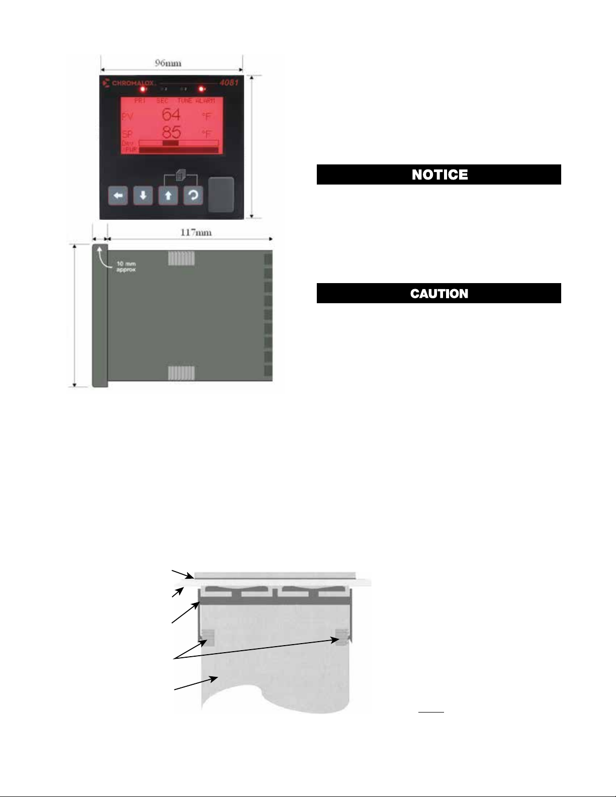
Figure 1. Main Dimensions
Gasket
Mounting Panel
Panel-Mounting
The mounting panel must be rigid and may be up to
6.0mm (0.25 inches) thick. The cut-out size is:
92mm x 92mm (+0.5mm / -0.0mm).
Instruments may be mounted side-by-side in a multiple installation, but instrument to panel moisture and
dust sealing will be compromised. Allow a 20mm gap
above, below and behind the instrument for ventilation.
The cut-out width (for n instruments) is:
(96n - 4) mm or (3.78n - 0.16) inches
If panel sealing must be maintained, mount each instrument into an individual cut-out with 10mm or more
clearance between the edges of the holes.
Note: The mounting clamp tongues may engage the
ratchets either on the sides or the top/bottom faces
of the Instrument housing. When installing several
Instruments side-by-side in one cut-out, use the
ratchets on the top/bottom faces.
Ensure the inside of the panel remains within the
instrument operating temperature and that there
is adequate airflow to prevent overheating.
Note: For an effective IP66 seal against dust and
moisture, ensure gasket is well compressed against
the panel, with the 4 tongues located in the same
ratchet slot.
Do not remove the panel gasket, as this may
result in inadequate clamping and sealing of
the instrument to the panel.
Once the instrument is installed in its mounting panel, it
may be subsequently removed from its housing if necessary, as described in the Fitting and Removing Plugin Modules section.
Cleaning
Clean the front panel by washing with warm soapy
water and dry immediately. If the USB option is fitted,
close the USB port cover before cleaning.
Clamp
Ratchets
Instrument
Housing
Figure 2. Panel-Mounting
2
1. Insert instrument into the
panel cut-out.
2. Hold front bezel firmly
(without pressing on the
display area), and re-fit
mounting clamp. Push the
clamp forward, using a tool if
necessary, until gasket
compresses and instrument
is held firmly
in position.
Page 11

3 Field Upgrade Options
Plug-Modules and Upgradeable Functions
Plug-Modules can be either pre-installed at the time
of manufacture, or retrofitted in the field to expand the
capabilities of the controller. Contact your supplier to
purchase these items. Part numbers and circuit board
identification numbers for the plug-in modules and accessories are shown in below:
Table 1. Options and Accessories
Plastic pegs prevent fitting of older non-reinforced single relay modules (Board Identification Numbers 637/01 and 638/01). Fitting the
older relay modules reduces the isolation rating to Basic 240V Isolation and is therefore not
recommended. Remove this peg when fitting
Dual Relay Modules.
PAR T
NUMBER DESCRIPTION
OPTION SLOT (OUTPUT) 1
0149-50043
0149-50044
0149-50077
0149-50047
OPTION SLOT (OUTPUT) 2 OR 3
0149-50050
0149-50049
0149-50051
0149-50052
0149-50070
0149-50053
OPTION SLOT A
0149-50056
0149-50057
0149-50055
0149-50058
ACCESSORIES
0149-50063
0149-50092
0149-50086
0149-50088
Single Relay Output for option slot (Output) 1 716/01
Single SSR Driver Output for option slot (Output) 1 716/02
Triac Output for option slot (Output) 1
Linear mA / Voltage Output module for option slot (Output) 1
Single Relay Output for option slot (Output) 2 or 3
Dual Relay Output for option slot (Output) 2 or 3
Single SSR Driver Output for option slot (Output) 2 or 3
Dual SSR Driver Output for option slot (Output) 2 or 3
Triac module Output for slot (Output) 2 or 3
24VDC Transmitter Power Supply for option slot (Output) 2 or 3
Digital Input for plug-in module slot A
Basic Auxiliary Input for plug-in module slot A
RS485 Serial Communications for plug-in module slot A
Ethernet Communications for plug-in module slot A
Profiler Enable Key-code
ChromaloxPro Configuration Software Only (60 & 80 Series)
Univ S/W Converter & PC Cable 20/40/50/60/80 Series
Cable Only – 40/50/80 Series to Universal Adaptor
BOARD IDENTIFICATION
NUMBER
716/01
716/02
716/03
639/01
717/01
644/01
717/02
644/02
647/01
642/01
641/02
653/01
680/01
707/01
3
Page 12
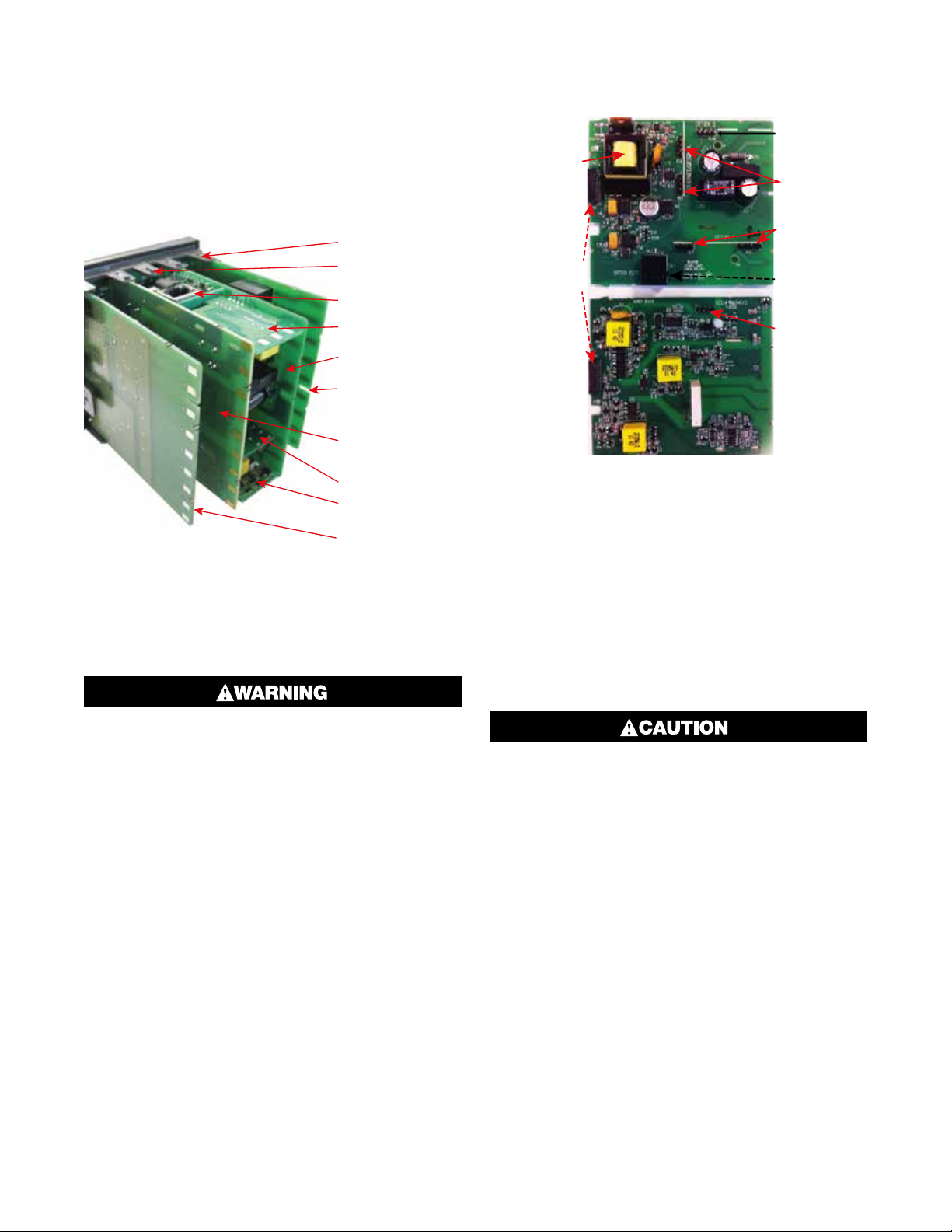
Board Positions
Board Mounting
l Latch (x1)
Board
100
Main Board Connectors
Note: All dual relay modules have reinforced isolation.
Struts (x4)
Front Panel
Remova
Plug-in Module A
Plug-in Module 3
Power Supply
2nd Universal Input
& Base Option 2
Board
1st Universal Input
& Base Option 1
Board
Plug-in Module 1
Plug-in Module 2
USB/Digital Input
C Option Board
Figure 3. Rear View (uncased) & Board Positions
Preparing to Install or Remove Options
Modules
POWER SUPPLY
BOARD
Transformer
Color Code
-240V (Yellow)
24-48V(Blue)
Display Board
Connections
1st UNIVERSAL
INPUT / BASE
OPTION 1
BOARD
Module Slot 3
Connector PL4B
Module Slot A
Connectors
PL5, & PL6
Module Slot 1
Connectors
PL7 & PL8
PC Configurator
Socket SK1
Module Slot 2
Connector PL4A
Figure 4. Main Board Connectors
This product is designed to allow the user to reconfigure some hardware options in the field by changing
the plug-in modules in slots 1, 2, 3, & A located on
the power supply and 1st universal input boards. The
main boards (display/CPU, power supply, inputs 1 &
2 and digital input/USB) are factory fitted, but may be
removed while reconfiguring the plug-in modules. Take
care when re-fitting these boards. Observe the power
supply board transformer color, and case labelling to
check the supply voltage, otherwise irreparable damage may occur.
ELECTRIC SHOCK HAZARD. Disconnect all
power before installing or servicing controller.
Failure to do so could result in personal injury
or property damage.
1. Grip the edges of the front panel (there is a finger
grip on each edge) and pull it forwards approximately 10mm, until the Front Panel Removal Latch
prevents further movement. The purpose of the
latch is to prevent removal of the instrument without
the use of a tool.
2. The Front Panel Removal Latch must be pushed
down to allow removal of the instrument. Using
a tool (e.g. screwdriver or pen tip), press down it
down through the front central ventilation hole. This
will release the instrument from the case.
3. The internal boards can now be accessed. Take
note of the orientation of the instrument and boards
for subsequent replacement into the housing. The
positions of the boards, their mountings and the
Front Panel Removal Latch are shown above.
Replacement of boards must be carried out by
a technically competent technician. If the Power Supply board does not match the labelling,
users may apply incorrect voltage resulting in
irreparable damage.
Removing/Replacing Option Modules
1. To remove or replace Plug-in Modules 1, 2, 3 or A it
is necessary to detach the power supply and input
boards from the front panel by lifting first the upper
and then lower mounting struts.
2. Remove or fit the modules to the connectors on the
power supply and input boards. The location of the
connectors is shown below. Plastic pegs prevent
fitting of older nonreinforced single relay modules –
Remove the peg to fit dual relay modules
3. Assemble the Power Supply and Input boards together. Tongues on each option module locate into
slots cut into the main boards, opposite each of the
connectors. Hold the Power and Input boards together and relocate them back on their mounting
struts.
4
Page 13

4. Push the boards forward to ensure correct connection to the front Display/CPU board and re-check
the installation of the Option C and/or 2nd Input /
Base Option 2 boards if present.
Check for correct orientation of the modules
and that all pins are located correctly.
Replacing the Instrument in its Housing
Data Recorder Board
If installed, the Data Recorder memory and Real Time
Clock (RTC) components are located on a plug-in
daughter board attached to the front Display/CPU
board.
Servicing of the Data Recorder/RTC circuit and
replacement of the lithium battery should only
be carried out by a technically competent technician.
ELECTRIC SHOCK HAZARD. Disconnect all
power before installing or servicing controller.
Failure to do so could result in personal injury
or property damage.
With the required option modules correctly located
into their respective positions the instrument can be
replaced into its housing as follows:
1. Hold the Power Supply and Input boards together.
2. Align the boards with the guides in the housing.
3. Slowly and firmly, push the instrument into position
in its case.
Ensure that the instrument is correctly orientated. A mechanical stop will operate if an
attempt is made to insert the instrument in
the wrong orientation, this stop MUST NOT be
over-ridden.
Auto Detection of Plug-in Modules
The instrument automatically detects which plug-in
modules have been fitted into each slot. The menus
and screens change to reflect the options compatible
with the hardware. The modules fitted can be viewed in
the product information menu, as detailed in the Product & Service Information Mode section of this manual.
Profiler Enabling
If you purchased a controller with the Profiler option
installed, these features will be enabled during manufacture.
Controllers supplied without the Profiler option installed can be upgraded in the field by purchasing a
licence code number from your supplier. A unique code
must be purchased to enable profiling on each controller that requires it.
Entering the Profiler Enable Code
Hold down the and keys during the power-up
“splash screen”.
Using the or keys, enter the 16-character licence code in the displayed screen.
Press to move on to the next character. Press to
move back to the previous character.
Press after entering the final character.
To confirm if profiling is installed in your instrument,
check the Controller Feature Information in Product &
Service Information Mode.
5
Page 14
4 Electrical Installation
ELECTRIC SHOCK/FIRE HAZARD. Installation
should be only performed by technically competent personnel. It is the responsibility of the
installing engineer to ensure that the configuration is safe. Local Regulations regarding electrical installation & safety must be observed
(e.g. US National Electrical Code (NEC) or Canadian Electrical Code). Failure to follow these
instructions could result in personal injury or
death and/or equipment / property damage.
Avoiding EMC Problems
This controller has passed EMC compliance tests to
EN61326. There should be no difficulty achieving this
level of compliance in use, but it should be borne in
mind that the wiring of the installation can significantly
reduce the efficiency of instrumentation immunity due
to the ease with which high frequency RF can enter via
unprotected cables.
The following general recommendations can reduce
the possibility of EMC problems.
1. If the instrument is being installed in existing equipment, wiring in the area should be checked to ensure that good wiring practices have been followed.
2. The controller should be mounted in a properly
earthed metal cabinet. All round metal shielding is
important, so the cabinet door may require a conductive sealing strip.
3. It is good practice to ensure that the AC neutral is at
or near ground (earth) potential. A proper neutral will
help ensure maximum performance from the instrument.
4. Consider using a separate isolation transformer to
feed only the instrumentation. A transformer can
protect instruments from noise found on the AC
power supply.
tween them. If wires MUST cross each other, ensure
they do so at 90 degrees to minimize interference.
Keep signal cables as short as possible. If an earthed
thermocouple is used or if the sensor has a screened
cable, it should be earthed at one point only, preferably
at the sensor location or cabinet entry point, by means
of a metal gland. Ideally all analogue and digital signals
should be shielded like this, but for unscreened cables,
large diameter ferrite sleeves at the cabinet entry point
are an effective method of reducing RF interference.
Looping cables through the ferrite sleeves a number of
times improves the efficiency of the filtering. For mains
input cables the fitting a suitable mains filter can provide good results.
Noise Suppression at Source
If possible, eliminate mechanical contact relays and
replace with solid-state relays. Noise-generating devices such as Ignition transformers, arc welders, motor drives, relays and solenoids should be mounted in
a separate enclosure. If this is not possible, separate
them from the instrumentation, by the largest distance
possible.
Many manufacturers of relays, contactors etc supply
‘surge suppressors’ to reduce noise at its source. For
those devices that do not have surge suppressors supplied, Resistance-Capacitance (RC) networks and/or
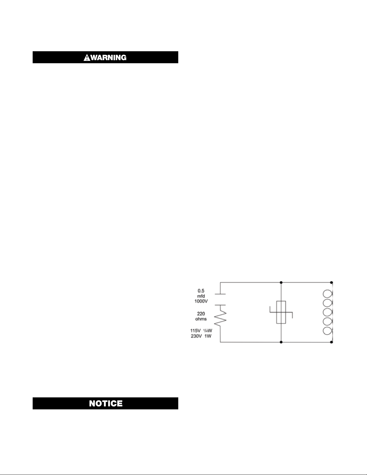
Metal Oxide Varistors (MOV) may be added.
Inductive coils: MOVs are recommended for transient
suppression in inductive coils. Connect as close as
possible, in parallel to the coil. Additional protection
may be provided by adding an RC network across the
MOV.
Cable Isolation & Protection
Four voltage levels of input and output wiring may be
used with the unit:
1. Analog inputs or outputs (for example thermocouple, RTD, VDC, mVDC or mADC)
2. Relays & Triac outputs
3. Digital Inputs & SSR Driver outputs
4. AC power
The only wires that should run together are
those of the same category.
If any wires need to run parallel with any from another
category, maintain a minimum space of 150mm be-
Figure 5. Transient Suppression
with Inductive Coils
Contacts: Arcing may occur across contacts when
they open and close. This results in electrical noise as
well as damage to the contacts. Connecting a properly
sized RC network can eliminate this arc.
For circuits up to 3 amps, a combination of a 47 ohm
resistor and 0.1 microfarad capacitor (1000 volts) is
recommended. For circuits from 3 to 5 amps, connect
two of these in parallel.
6
Page 15
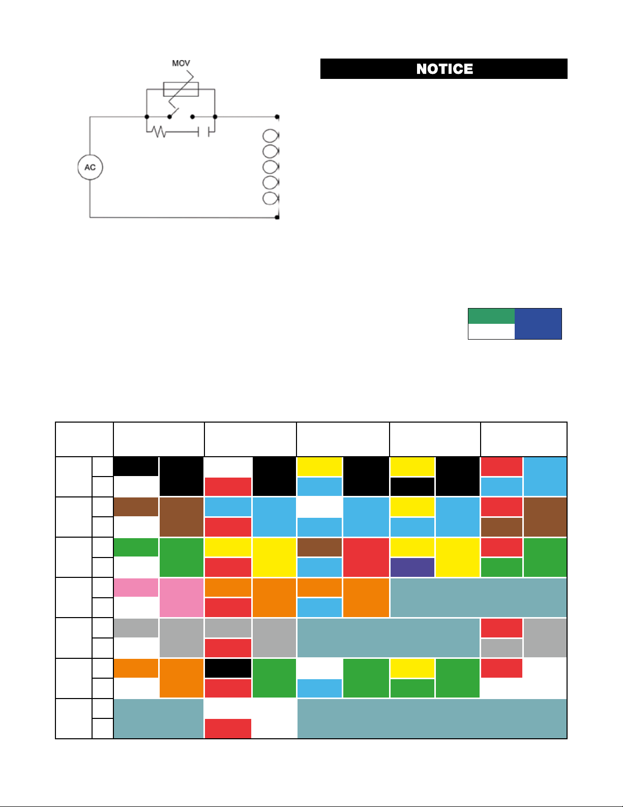
Figure 6. Contact Noise Suppression
Sensor Placement (Thermocouple or RTD)
If a temperature probe is to be subjected to corrosive
or abrasive conditions, it must be protected by an appropriate thermowell.
Probes must be positioned to reflect the true process
temperature:
1. In a liquid media - the most agitated area
2. In air - the best circulated area
The placement of probes into pipe work some
distance from the heating vessel leads to transport delay, which results in poor control.
For a two wire RTD, a wire link should be used in place
of the third wire (see the wiring section for details). Two
wire RTDs should only be used with lead lengths less
than 3 metres.
Use of three wire RTDs is strongly recommended to
reduce errors do to lead resistance.
Thermocouple Wire Identification
The different thermocouple types are identified by their
wires color, and where possible, the outer insulation
as well. There are several standards in use throughout
the world, but most regions now use the International
IEC584-3 standard.
The table below shows the wire and sheath colors used
for most common thermocouple types. The format
used in this table is:
+ Wire
Sheath
- Wire
Type
J +*
T +
K +
-*
N +
B +
R & S +
Table 2. Thermocouple Extension Wire Colors
International
IEC584-3
Black
-
White Red Blue Black Blue
Brown
-
White Red Blue Blue Brown
Green
White Red Blue Purple Green
Pink
-
White Red Blue
Grey
-
White Red Grey
Orange
-
White Red Blue Green White
Black
Brown
Green
Pink
Grey
Orange
USA ANSI
MC 96.1
White
Black
Blue
Blue
Yellow
Yellow
Orange
Orange
Grey
Grey
Black
Green
British
BS1843
Yellow
Black
White
Blue
Brown
Red
Orange
Orange
White
Green
French
NFC 42-324
Yellow
Black
Yellow
Blue
Yellow
Yellow
Yellow
Green
German
DIN 43710
Red
Blue
Red
Brown
Red
Green
Red
Grey
Red
White
C
(W5)
*Wire is magnetic. a magnet can be used to assist with correctly identifying the type and polarity of the conductors
+
-
White
White
Red
7
Page 16

Pre-Wiring: Cautions, Warnings
& Information
Installation should be only performed by technically competent personnel. It is the responsibility of the installing engineer to ensure that
the configuration is safe. Local Regulations
regarding electrical installation & safety must
be observed (e.g. US National Electrical Code
(NEC) or Canadian Electrical Code).
ELECTRIC SHOCK/FIRE HAZARD. THIS EQUIPMENT IS DESIGNED FOR INSTALLATION IN AN
ENCLOSURE THAT PROVIDES ADEQUATE PROTECTION AGAINST ELECTRIC SHOCK. THE
ISOLATION SWITCH SHOULD BE LOCATED
IN CLOSE PROXIMITY TO THE UNIT, IN EASY
REACH OF THE OPERATOR AND APPROPRIATELY MARKED. FAILURE TO FOLLOW THESE
INSTRUCTIONS COULD RESULT IN PERSONAL INJURY OR DEATH AND/OR EQUIPMENT /
PROPERTY DAMAGE.
This symbol means the equipment is
protected throughout by double insulation. All external circuits connected
must provide double insulation. Failure to comply with the installation instructions may impact the protection
provided by the unit.
ELECTRIC SHOCK/FIRE HAZARD. TO AVOID
ELECTRICAL SHOCK, AC POWER WIRING MUST
NOT BE CONNECTED TO THE SOURCE DISTRIBUTION PANEL UNTIL ALL WIRING PROCEDURES ARE COMPLETED. CHECK THE INFORMATION LABEL ON THE CASE TO DETERMINE
THE CORRECT VOLTAGE BEFORE CONNECTING TO A LIVE SUPPLY. FAILURE TO FOLLOW
THESE INSTRUCTIONS COULD RESULT IN PERSONAL INJURY OR DEATH AND/OR EQUIPMENT
/ PROPERTY DAMAGE.
8
Page 17
OPTION
OPTION
Connections and Wiring
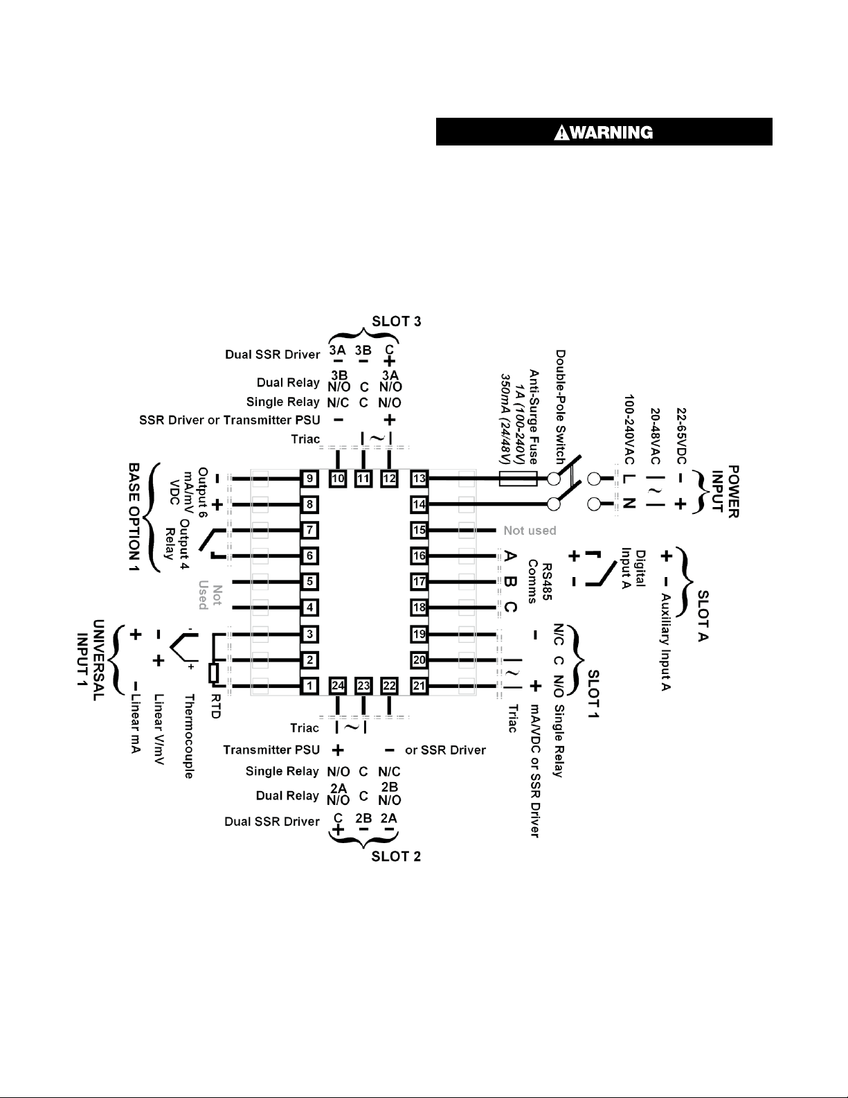
Central Terminal Connections
Note: The wiring diagram below shows all possible
combinations to the main connections (numbered 1
to 24) in the centre of the case rear. The actual connections required depends upon the features and
modules fitted.
ELECTRIC SHOCK/FIRE HAZARD. CHECK THE
INFORMATION LABEL ON THE CASE TO DETERMINE THE CORRECT VOLTAGE BEFORE
CONNECTING TO A LIVE SUPPLY. FAILURE TO
FOLLOW THESE INSTRUCTIONS COULD RESULT IN PERSONAL INJURY OR DEATH AND/OR
EQUIPMENT / PROPERTY DAMAGE.
OPTION
Figure 7. Central Terminals 1 to 24
OPTION
9
Page 18
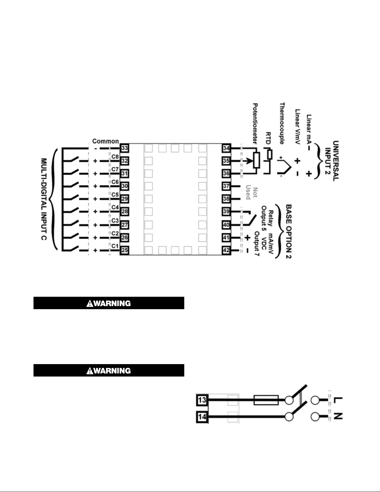
Outer Terminal Connections
Note: The wiring diagram below shows the Central Terminals (numbered 25 to 42) at the sides of
the case rear. Connections for the 2nd Input, Base
Option 2 and Digital Input C are shown. The actual
connections required depends upon the features
and modules fitted.
Figure 8. Outer Terminals 25 to 42
Power Connections
ELECTRIC SHOCK/FIRE HAZARD. CHECK THE
INFORMATION LABEL ON THE CASE TO DETERMINE THE CORRECT VOLTAGE BEFORE
CONNECTING TO A LIVE SUPPLY. FAILURE TO
FOLLOW THESE INSTRUCTIONS COULD RESULT IN PERSONAL INJURY OR DEATH AND/OR
EQUIPMENT / PROPERTY DAMAGE.
ELECTRIC SHOCK/FIRE HAZARD. THIS EQUIPMENT IS DESIGNED FOR INSTALLATION IN AN
ENCLOSURE THAT PROVIDES ADEQUATE PROTECTION AGAINST ELECTRIC SHOCK. THE
ISOLATION SWITCH SHOULD BE LOCATED
IN CLOSE PROXIMITY TO THE UNIT, IN EASY
REACH OF THE OPERATOR AND APPROPRIATELY MARKED. FAILURE TO FOLLOW THESE
INSTRUCTIONS COULD RESULT IN PERSONAL INJURY OR DEATH AND/OR EQUIPMENT /
PROPERTY DAMAGE.
Power Connections - Mains Powered
Instruments
Mains powered instruments operate from a 100 to
240V (±10%) 50/60Hz supply. Power consumption is
20VA. Connect the line and neutral as illustrated via a
UL listed fuse type: 250V AC 1Amp anti-surge and a
two-pole IEC60947-1 & IEC60947-3 compliant isolation switch / circuit breaker located within easy reach
of the operator and appropriately marked. If relays
switch mains voltage this should be separate from the
instruments mains supply.
Figure 9. Mains Power Connections
10
Page 19
Power Connections - 24/48V AC/DC
Powered Instruments
24/48V AD/DC powered instruments will operate from
a 20 to 48V AC or 22 to 55V DC supply. AC power consumption is 15VA max, DC power consumption is 12
watts max. Connection should be via a UL listed fuse
type: 65v dc 350mAamp anti-surge and a two-pole
IEC60947-1 & IEC60947-3 compliant isolation switch /
circuit breaker located within easy reach of the operator and appropriately marked.
Figure 10. 24/48V AC/DC Power
Connections
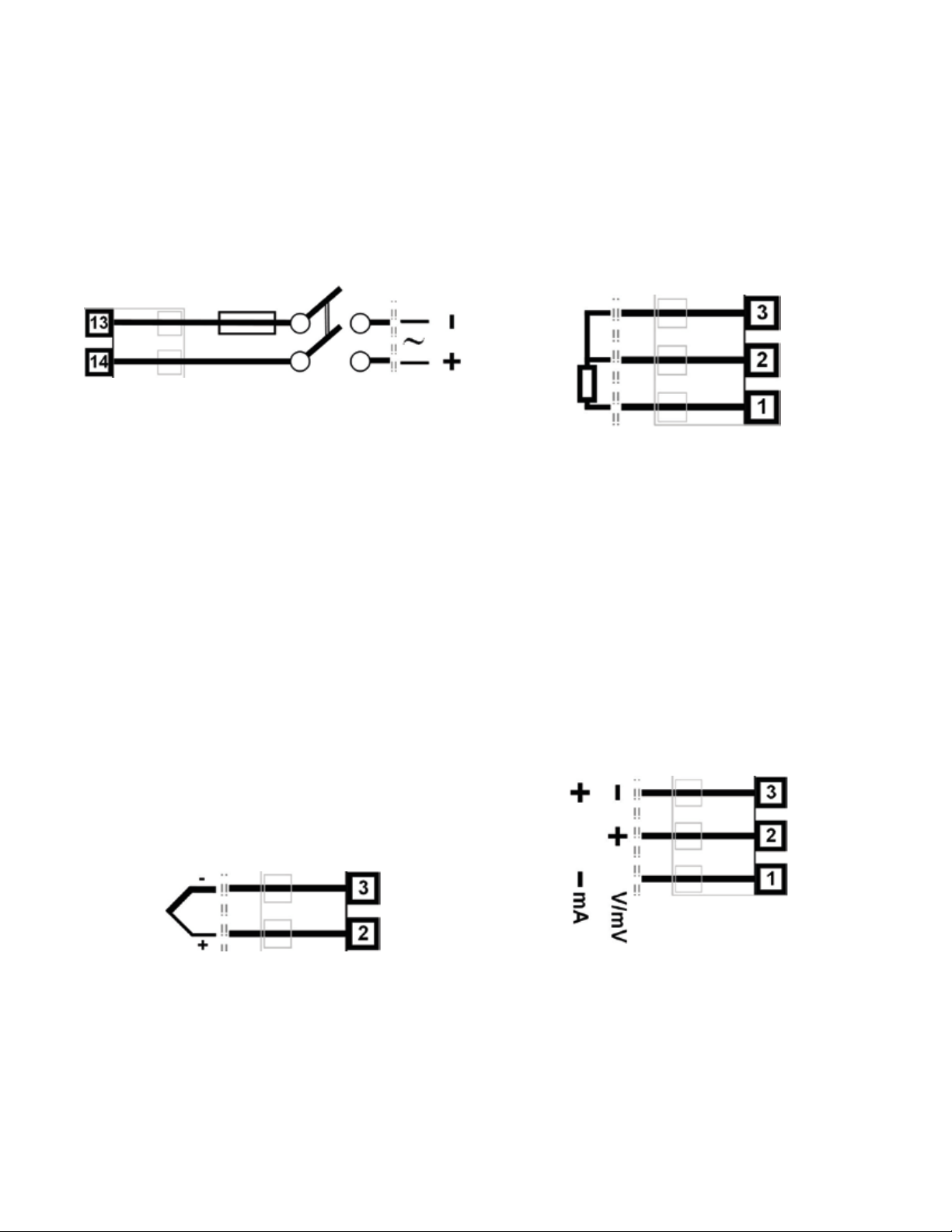
Universal Input 1 Connections – PT100 /
NI120 (RTD) input
The inputs supports two types of RTD. PT100 (platinum sensor, 100Ω at 0°C). For three wire RTDs, connect the resistive leg and the common legs of the RTD
as illustrated. For a two wire RTD a wire link should be
fitted across terminals 2 & 3 (in place of the third wire).
Two wire RTDs should only be used when the leads are
less than 3 metres long. Avoid cable joints.
Universal Input 1 Connections
Universal Input 1 is present on all models. This input is
normally used for the measured variable signal from a
process to be controlled. It can be connected to thermocouples; resistance temperature detectors; analogue mA; mV or V DC signals. The input settings are
in the Input 1 Configuration sub-menu. Connections for
the various types are shown below. Ensure that the signal is correctly connected, paying particular attention
to the polarity.
Universal Input 1 Connections Thermocouple (T/C)
Supported thermocouple types & ranges are listed in
the input specifications section on page 245. Only use
the correct thermocouple wire or compensating cable
from the sensor to the instrument terminals avoiding
joints in the cable if possible. Where joints are made,
special thermocouple connectors must be used. Failure to use the correct wire type and connectors will
lead to inaccurate readings. Ensure correct polarity of
the wires by cross-referencing the colors with the thermocouple reference table.
Figure 12. Input 1 - RTD Connections
Four wire RTDs can be used, provided that the fourth
wire is left unconnected. This wire should be cut short
or tied back so that it cannot contact any of the terminals on the rear of the instrument.
Universal Input 1 Connections - Linear
Volt, mV or mA input
The input supports the following linear/analogue signals: 0 to 50mV; 10 to 50mV; 0 to 5V; 1 to 5V; 0 to
10V; 2 to 10V; 0 to 20mV; 4 to 20mA from any suitable source. Voltage & millivolt signals are connected
to terminals 2 & 3, milliamp signals are connected to
1 & 3. Carefully observe the position & polarity of the
connections.
Figure 11.
Input 1 - Thermocouple Connections
Figure 13. Input 1 - DC Volt, mV & mA Connections
11
Page 20
Universal / Auxiliary Input 2 Connections
An Auxiliary Input 2 option is fitted to some models.
This can connect to a potentiometer; analogue mA; mV
or V DC signal for a remote setpoint input signal, or for
flow/valve position feedback information. Alternatively,
a second Universal Input 2 option may be fitted. In addition to the remote setpoint input signal or feedback
information possible with the auxiliary input, the 2nd
Universal Input can be used as a second process control loop for two control loops, or used in conjunction
with input one in more complex single control loops.
Universal Input 2 can be connected to thermocouples;
resistance temperature detectors; potentiometers; analogue mA; mV or V DC signals.
The settings are in the Input 2 Configuration sub-menu.
Connections for the various types are shown below.
Ensure that the signal is correctly connected, paying
particular attention to the polarity.
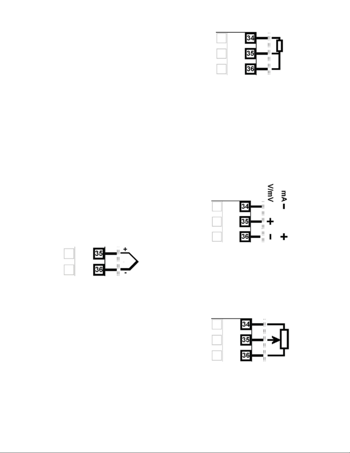
Universal Input 2 Connections Thermocouple (T/C)
The optional 2nd universal input, supports various
thermocouple types. Supported types & ranges are
listed in the input specifications section on page 245.
Only use the correct thermocouple wire or compensating cable from the sensor to the instrument terminals
avoiding joints in the cable if possible. Where joints are
made, special thermocouple connectors must be used.
Failure to use the correct wire type and connectors will
lead to inaccurate readings. Ensure correct polarity of
the wires by cross-referencing the colors with a thermocouple reference table.
Figure 15. Input 2 - RTD Connections
Four wire RTDs can be used, provided that the fourth
wire is left unconnected. This wire should be cut short
or tied back so that it cannot contact any of the terminals on the rear of the instrument.
Universal / Auxiliary Input 2 Connections Linear Volt, mV or mA input
The optional auxiliary or 2nd universal input supports
the following linear/analogue signals: 0 to 50mV; 10 to
50mV; 0 to 5V; 1 to 5V; 0 to 10V; 2 to 10V; 0 to 20mV;
4 to 20mA from any suitable source. Voltage & millivolt signals are connected to terminals 2 & 3, milliamp
signals are connected to 1 & 3. Carefully observe the
polarity of the connections.
Figure 14. Input 2 - Thermocouple Connections
Universal Input 2 Connections –
PT100 / NI120 (RTD) Input
The optional 2nd universal input, supports two types of
RTD. PT100 (platinum sensor, 100Ω at 0°C). For three
wire RTDs, connect the resistive leg and the common
legs of the RTD as illustrated. For a two wire RTD a wire
link should be fitted across terminals 35 & 36 (in place
of the third wire). Two wire RTDs should only be used
when the leads are less than 3 metres long. If possible,
avoid cable joints.
Figure 16. Input 2 - DC Volt, mV & mA Connections
Universal / Auxiliary Input 2 Connections –
Potentiometer
The optional auxiliary or 2nd universal input, the terminals detailed below can be used to connect a feedback
potentiometer. Minimum potentiometer resistance is
≥100Ω.
Figure 17. Input 2 - Potentiometer Connections
12
Page 21
Base Option 1
Base Option 1 provides one or two factory fitted outputs. A relay designated as Output 4 is fitted on all
models, and an optional linear mA/V DC designated as
Output 6. Base options cannot be added after manufacture. The functions of outputs 4 & 6 are set in the
Output Configuration sub-menu. Connect as illustrated
below.
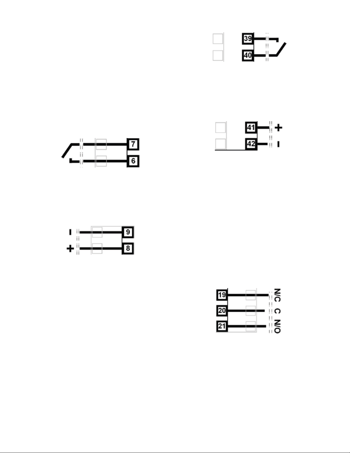
Base Option 1 Relay Output 4
Present on all instruments, Output 4 is a SPST relay,
rated at 2 amps at 240 VAC resistive. If it is used to
switch mains voltages, the supply should be separate
from the instrument supply and should be correctly
switched and fused.
Figure 20. Relay Output 5 Connections
Base Option 2 Linear Output 7
Part of base option 2, Output 7 is an optional linear
mV/V DC analogue output. The type & range are selectable from 0 to 5, 0 to 10, 2 to 10V & 0 to 20 or 4 to
20mA.
Figure 21. Linear Output 7 Connections
Figure 18. Relay Output 4 Connections
Base Option 1 Linear Output 6
Part of base option 1, Output 6 is an optional linear
mV/V DC analogue output. The type & range are selectable from 0 to 5, 0 to 10, 2 to 10V & 0 to 20 or 4 to
20mA.
Figure 19. Linear Output 6 Connections
Base Option 2
Base Option 2 provides one or two factory fitted outputs. An optional relay designated as Output 5, and an
optional linear mA/V DC designated as Output 7. Base
options cannot be added after manufacture. The functions of outputs 5 & 7 are set in the Output Configuration sub-menu. Connect as illustrated below.
Plug-in Module Slot 1 Connections
A selection of plug-in modules are available for Module Slot 1. They can be fitted during manufacture, or
purchased and fitted later by the user. Modules in slot
1 are designated Output 1. They are not interchangeable with those in slot 2 or 3. Their function is set in the
Output Configuration sub-menu. Connect as illustrated
below.
Plug-in Module Slot 1 – Single Relay Output Module
If fitted with a single relay output module, connect as
shown. The relay contacts are SPDT and rated at 2
amps resistive, 240 VAC. If it is used to switch mains
voltages, the supply should be separate from the instrument supply and should be correctly switched and
fused.
Base Option 2 Relay Output 5
Part of base option 2, Output 5 is a SPST relay, rated
at 2 amps at 240 VAC resistive. If it is used to switch
mains voltages, the supply should be separate from the
instrument supply and should be correctly switched
and fused.
Figure 22.
Plug-in Module Slot 1 – Single Relay Module
Plug-in Module Slot 1 – Single SSR Driver
Output Module
If fitted with a single SSR Driver output module, connect as shown. The 10V DC pulse signal (load resistance ≥500 ohms) is isolated from all inputs/outputs
except other SSR drivers.
13
Page 22
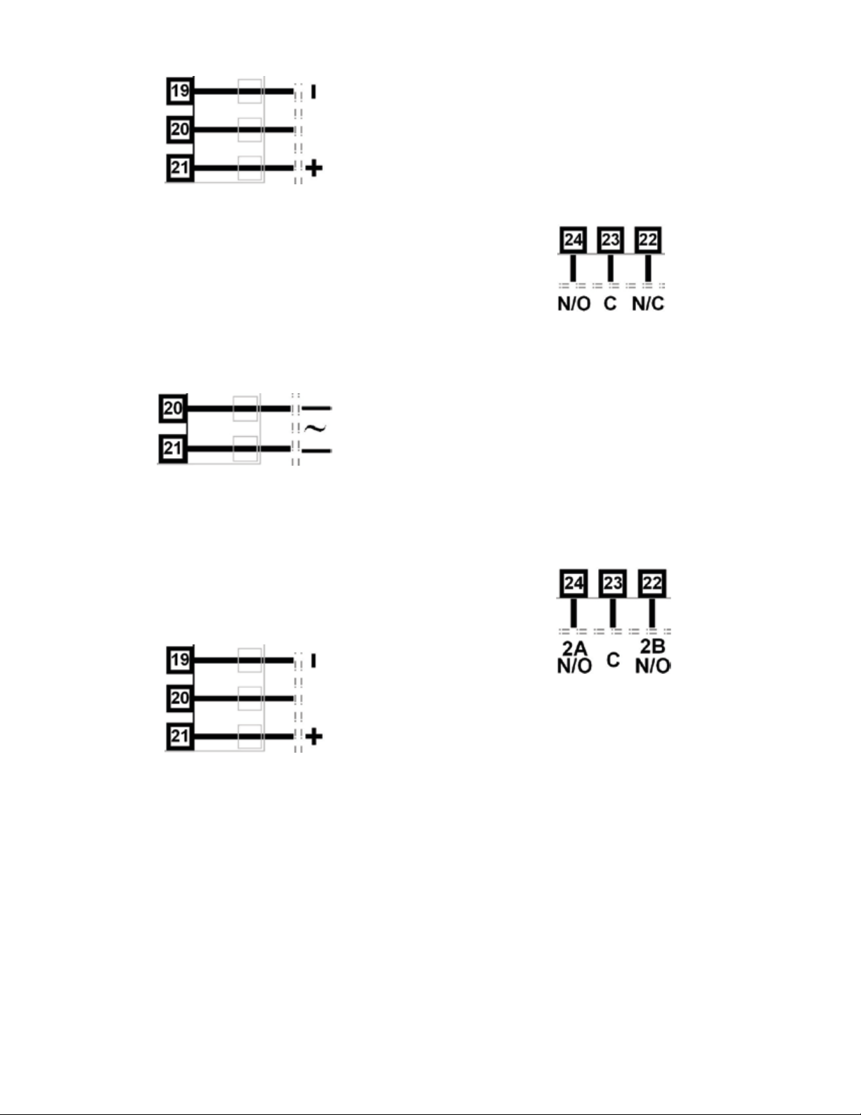
Figure 23.
Plug-in Module Slot 1 – Single SSR Driver Module
Plug-in Module Slot 1 -
Triac Output Module
If fitted with a triac output module, connect as shown.
This output is rated at 0.01 to 1 amp @ 280V AC
50/60Hz. Isolated from all other inputs and outputs. A
snubber should be fitted across inductive loads to ensure reliable switch off of the Triac.
Figure 24. Plug-in Module Slot 1 - Triac Module
Plug-in Module Slot 1 - Linear Voltage or
mADC Output module
If fitted with a DC linear output module, connect as
shown. Output type & range are selectable from 0 to 5,
0 to 10, 2 to 10V & 0 to 20 or 4 to 20mA. Isolated from
all other inputs and outputs.
Plug-in Module Slot 2 – Single Relay Output Module
If fitted with a single relay output module, connect as
shown. The relay contacts are SPDT and rated at 2
amps resistive, 240 VAC. If it is used to switch mains
voltages, the supply should be separate from the instrument supply and should be correctly switched and
fused.
Figure 26.
Plug-in Module Slot 2 – Single Relay Module
Plug-in Module Slot 2 - Dual Relay Output
Module
If fitted with a dual relay output module, connect as
shown. This module has two independent SPST relays
for outputs 2A and 2B, with a shared common terminal.
The contacts are rated at 2 amp resistive 240 VAC. If
used to switch mains voltages, the supply should be
separate from the instruments mains supply and the
contacts should be correctly switched and fused.
Figure 25. Plug-in Module Slot
1 - Linear Voltage & mADC Module
Plug-In Module Slot 2 Connections
A selection of plug-in modules are available for Module
Slot 2. They are interchangeable with slot 3, but not
slot 1.They can be fitted during manufacture, or purchased and fitted later by the user. Modules in slot 2
are designated Output 2, and for dual modules Output
2A and 2B. Their functions are set in the Output Configuration sub-menu. Connect as illustrated below.
Figure 27.
Plug-in Module Slot 2 - Dual Relay Module
Plug-in Module Slot 2 – Single SSR Driver
Output Module
If fitted with a single SSR Driver output module, connect as shown. The 10V DC pulse signal (load resistance ≥500 ohms) is isolated from all inputs/outputs
except other SSR drivers.
14
Page 23
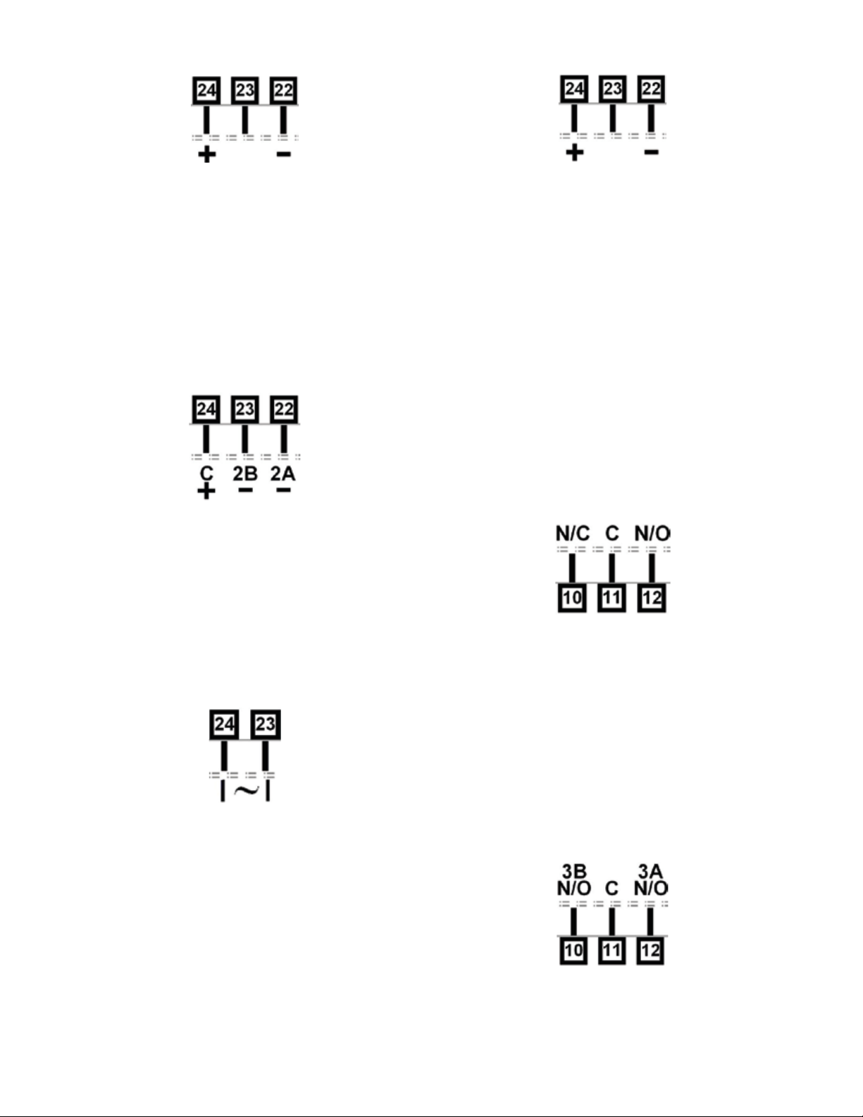
Figure 28.
Plug-in Module Slot 2 – Single SSR Driver Module
Figure 31. Plug-in Module Slot 2 -
Transmitter Power Supply Module
Plug-in Module Slot 2 – Dual SSR Driver
Output Module
If fitted with a dual SSR Driver output module, the two
solid-state relay driver outputs are designated as Output 2A and 2B. The outputs are 10V DC pulse signals,
(load resistance ≥500 ohms). They are isolated from all
inputs/output except other SSR driver outputs. Connect as shown making note of the shared positive
common terminal.
Figure 29.
Plug-in Module Slot 2 – Dual SSR Driver Module
Plug-in Module Slot 2 Triac Output Module
If fitted with a Triac output module, connect as shown.
This output is rated at 0.01 to 1 amp @ 280V AC
50/60Hz. Isolated from all other inputs and outputs. A
snubber should be fitted across inductive loads to ensure reliable switch off of the Triac.
Figure 30. Plug-in Module Slot 2 - Triac Module
Plug-in Slot 3 Connections
A selection of plug-in modules are available for Module
Slot 3. They are interchangeable with slot 2, but not
slot 1.They can be fitted during manufacture, or purchased and fitted later by the user. Modules in slot 3
are designated Output 3, and for dual modules Output
3A and 3B. Their functions are set in the Output Configuration sub-menu. Connect as illustrated below.
Plug-in Module Slot 3 –
Single Relay Output Module
If fitted with a single relay output module, connect as
shown. The relay contacts are SPDT and rated at 2
amps resistive, 240 VAC. If it is used to switch mains
voltages, the supply should be separate from the instrument supply and should be correctly switched and
fused.
Figure 32.
Plug-in Module Slot 3 – Single Relay Module
Plug-in Module Slot 3 - Dual Relay Output
Module
If fitted with a dual relay output module, connect as
shown. This module has two independent SPST relays
for outputs 3A and 3B, with a shared common terminal.
The contacts are rated at 2 amp resistive 240 VAC. If
used to switch mains voltages, the supply should be
separate from the instruments mains supply and the
contacts should be correctly switched and fused.
Plug-in Module Slot 2 Transmitter Power Supply Module
If fitted with a transmitter power supply module (TxPSU), connect as shown. The output is a 24V nominal
(unregulated, 19 to 28V DC), supply at 22mA max. Only
one TxPSU is supported, do not fit in slot 2 if one is
already fitted in slot 3.
Figure 33
Plug-in Module Slot 3 - Dual Relay Module
15
Page 24
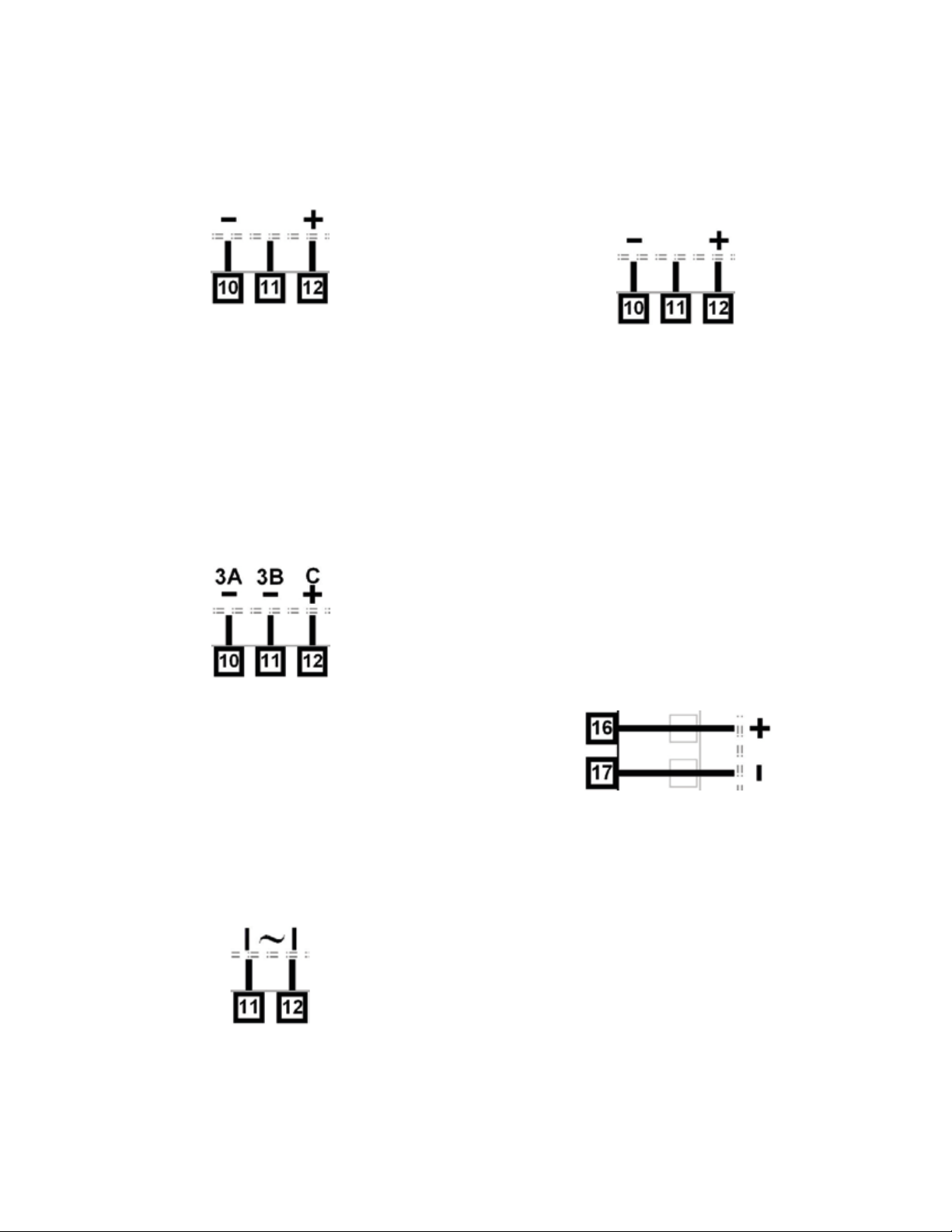
Plug-in Module Slot 3 – Single SSR Driver
Output Module
If fitted with a single SSR Driver output module, connect as shown. The 10V DC pulse signal (load resistance ≥500 ohms) is isolated from all inputs/outputs
except other SSR drivers.
Figure 34
Plug-in Module Slot 3 – Single SSR Driver Module
Plug-in Module Slot 3 – Dual SSR Driver
Output Module
If fitted with a dual SSR Driver output module, the two
solid-state relay driver outputs are designated as Output 3A and 3B. The outputs are 10V DC pulse signals,
(load resistance ≥500 ohms). They are isolated from all
inputs/output except other SSR driver outputs. Connect as shown making note of the shared positive
common terminal.
Plug-in Module Slot 3 - Transmitter Power
Supply Module
If fitted with a transmitter power supply module (TxPSU), connect as shown. The output is a 24V nominal
(unregulated, 19 to 28V DC), supply at 22mA max. Only
one TxPSU is supported, do not fit in slot 3 if one is
already fitted in slot 2.
Figure 37. Plug-in Module Slot 3 -
Transmitter Power Supply Module
Plug-in Slot A Connections
A selection of plug-in modules are available for Module Slot A. They can be fitted during manufacture, or
purchased and fitted later by the user. Depending on
their functions, they are setup Input or Communications configuration sub-menus. Connect as illustrated
below.
Figure 35.
Plug-in Module Slot 3 – Dual SSR Driver Module
Plug-in Module Slot 3 Triac Output Module
If fitted with a Triac output module, connect as shown.
This output is rated at 0.01 to 1 amp @ 280V AC
50/60Hz. Isolated from all other inputs and outputs. A
snubber should be fitted across inductive loads to ensure reliable switch off of the Triac.
Figure 36. Plug-in Module Slot 3 - Triac Module
Plug-in Module Slot A – Basic Auxiliary
Input Module
If fitted with a basic auxiliary mA/V DC analogue input
module, connect as shown. Isolated from all inputs/
outputs. Consider using the 2nd auxiliary input (if available) instead, as this has additional features and leaves
plug-in module slot A free for other modules.
Figure 38. Plug-in Module Slot A –
Basic Auxiliary Input Module
Plug-in Module Slot A Ethernet Communications Module
If fitted with the Ethernet communication module, the
communications protocol available is Modbus TCP.
Isolated from all inputs/outputs. If necessary, cut out
the removable panel to access the RJ45 connector
through the top of the case. No rear connections are
required.
16
Page 25

Plug-in Module Slot A RS485 Serial Communications Module
If fitted with the RS485 serial communication module,
the protocol used is Modbus RTU. Isolated from all
inputs/outputs. Carefully observe the polarity of the A
(Rx/Tx +ve) and B (Rx/Tx -ve) connections.
Figure 39. Plug-in Module Slot A –
RS485 Serial Communications Module
External computing devices connected to the
communications port should comply with the
standard, UL 60950.
Plug-in Module Slot A – Single Digital Input Module
If a digital input module is fitted, it provides a fully isolated input that is held high via a pull-up resistor. The
input can be connected to either to voltage free contacts (e.g. from a switch), or a TTL compatible signal.
Logic High = Open contacts (>5000Ω) or 2 to 24VDC
signal. Logic Low = Closed contacts (<50Ω) or -0.6 to
+0.8VDC signal.. Connect as shown.
Option C Connections – Multiple Digital
Input Module
If the Multiple Digital Input option is fitted, the connections are as illustrated. The 8 opto-isolated inputs each
have a positive input terminal and share a common
negative terminal. The inputs are held high with internal
pull-up resistors, so may be connected to either voltage free contacts (e.g. from a switch), or TTL compatible signals: Logic High = Open contacts (>5000Ω) or 2
to 24VDC signal. Logic Low = Closed contacts (<50Ω)
or -0.6 to +0.8VDC signal.
Figure 40. Plug-in Module Slot A –
Digital Input A Module
Option C Connections
Option C offers a factory fitted multiple digital input option. The board also accommodates the USB port if
that is option is fitted. The USB port does not have
connections on the rear terminal, it is accessed via the
front panel.
Figure 14. Input 2 - Thermocouple Connections
Special Wiring Considerations for Valve
Motor Control
Valve Motor Drive (VMD) controllers require two identical outputs to be assigned to position the valve. One
to open and one to close the valve. These outputs can
be two single relays, two triacs, two SSR drivers or one
dual relay, but it is recommended to use two single relays (SPDT change-over contacts), and to interlock the
relay wiring as shown. This prevents both motor windings from being driven at the same time, even under
fault conditions.
Switching actuators directly connected to the valve
motor must only be used up to half of their rated voltage (see CAUTION below). The internal relay and triac
outputs are rated at 240VAC, so the maximum motor
voltage when using them in this way is therefore 120V
unless interposing relays are used. Interposing relays
or other devices used to control the valve must themselves be rated for twice the motor supply voltage.
17
Page 26
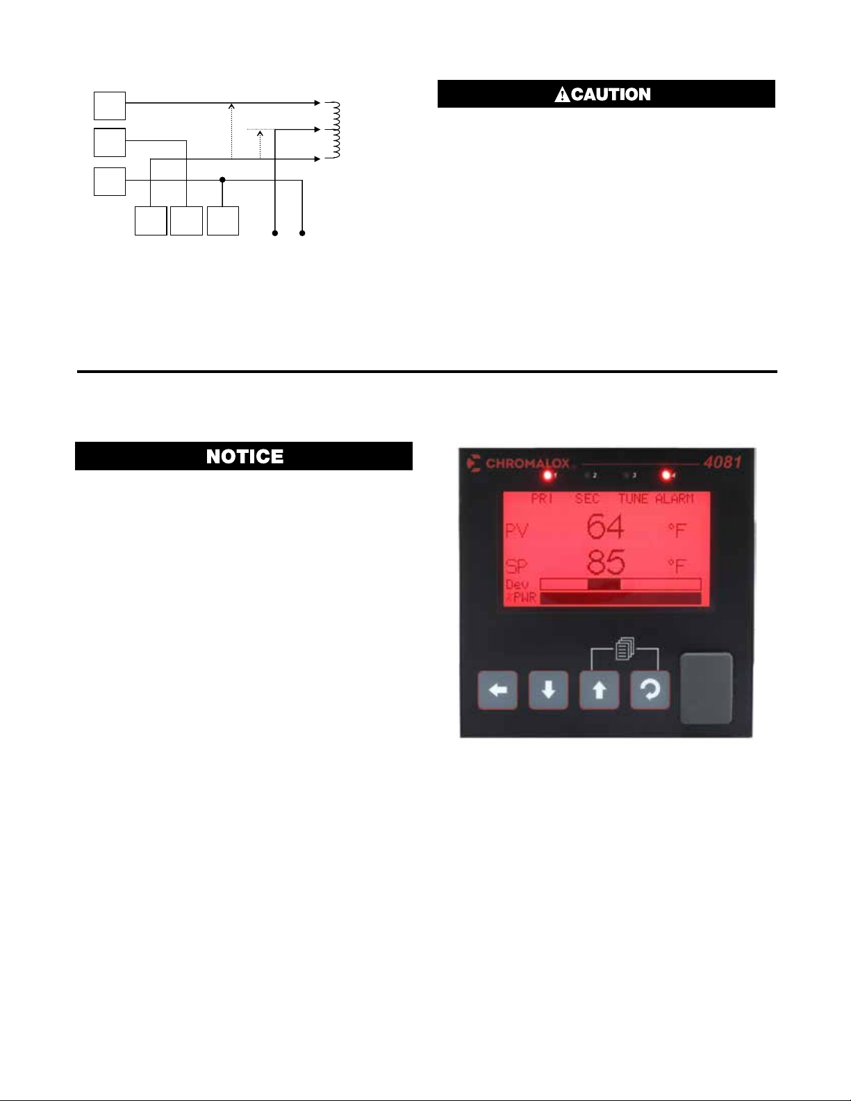
Open Valve
e
“OPEN” RELAY
N/O
C
N/C
“CLOSE” RELAY
2 x 120V = 240V
120V
N/C C N/O
N/C C N/O
120VAC SUPPLY
Winding
Valve
Common
Close Valv
Winding
Figure 42. Interlocking of Valve Motor Drive Relays
5 Powering Up
Ensure safe wiring practices have been followed. When
powering up for the first time, disconnect the output
connections. The instrument must be powered from
a supply according to the wiring label on the side of
the unit. The supply will be either 100 to 240V AC, or
24/48V AC/DC powered. Check carefully the supply
voltage and connections before applying power
ELECTRIC SHOCK/FIRE HAZARD. The windings
of a valve motor effectively form an autotransformer. This has a voltage doubling effect when
power is applied to either the Open or Close
terminal, causing twice the supplied voltage at
the other terminal. For this reason, switching
devices directly connected to the valve motor must only be used up to half of their rated
voltage. The maximum motor voltage when using the internal relays/triacs is therefore 120V
unless interposing relays are used. Interposing relays or other devices used to control the
valve must themselves be rated for twice the
motor supply voltage. Failure to follow these
instructions could result in personal injury or
equipment damage.
Powering Up Procedure
At power up, a self-test procedure is automatically
started, during which a splash screen is displayed and
the LED indicators are lit. At the first power up from
new, a Setup Wizard runs to assist configuration of basic applications (refer to the Setup Wizard section on
page 43). At all other times, the instrument returns to
the normal operation mode once the self-test procedure is complete.
Front Panel Overview
The illustration below shows an instrument fitted with
the optional USB socket located to the right of the four
keypad buttons. Clean the front panel by washing with
warm soapy water and dry immediately. If the USB option is fitted, close the port cover before cleaning.
Display
The instrument has a 160 x 80 pixel monochrome
graphical display with dual color (red/green) backlight.
The main display typically shows the process variables,
setpoints, power / deviation bar graphs or graphical
trends during normal operation. There are recorder and
profile status screen. The top line of the display has
labels for the 4 LED indicators. If desired, the backlight color can be changed to indicate the presence of
an active alarm or latched output. Refer to the Display
Configuration section.
Figure 43. A Typical Front Panel
18
Page 27
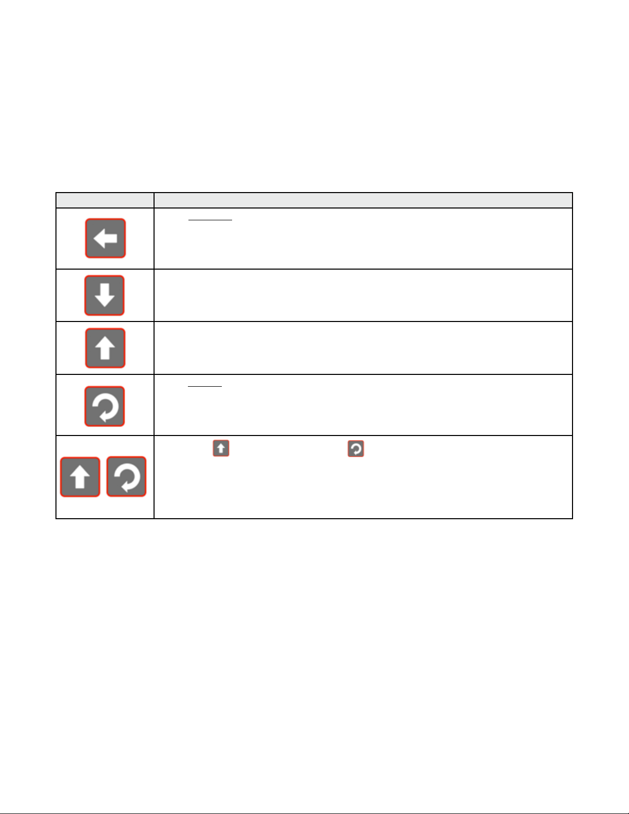
LED Functions
There are four red LEDs that by default indicate the
status of the primary & secondary outputs, automatic
tuning and alarm status. The top line of the graphical
display has four labels for LED indicators. The function
of these LEDs and their display labels can be changed
using the PC configuration software. The information
in this manual assumes standard functions for these
LEDs.
Button Function
Moves backward to the previous parameter or screen in the current mode. Holding this key down
for more than 1 second skips immediately to the previous screen accepting ALL values as shown.
CAUTION: If editing a parameter, ensure that the current (highlighted) parameter value is correct before pressing the key as this action will update the instrument to the
value displayed.
In menus and configuration choice screens, this key moves to the next item on the list.
Editable values can be decreased by pressing this key. Holding the key down speeds up the change.
In Trend views this key moves the Cursor Line back through the stored data points
In menus and configuration choice screens, this key moves to the previous item on the list.
Editable values can be increased by pressing this key. Holding the key down speeds up the change.
In Trend views this key moves the Cursor Line forward through the stored data points
Moves forward to the next parameter or screen in the current mode. Holding this key down for more
than 1 second skips immediately to the next screen accepting ALL values as shown.
CAUTION: If editing a parameter, ensure that the current (highlighted) parameter value is correct before pressing the key as this action will update the instrument to the
value displayed.
Keypad Functions & Navigation
Each instrument has four keypad switches, which are
used to navigate through the user menus and adjust
the parameter values. In configuration screens, a context sensitive scrolling help text is displayed that guides
the user about the function of the keys.
Pressing the key while holding down the key causes the instrument to move up one menu
level. From Operation Mode and in most menus, this will result in entry to the Main Menu.
From sub-menus, it is necessary to carry out this sequence more than once to reach the main menu.
CAUTION: If editing a parameter, ensure that the current (highlighted) parameter value is correct before pressing the key as this action will update the instrument to the
value displayed.
19
Page 28

6 Messages and Error Indicators
Plug-in Module Problems
If an invalid or unknown module is detected in one of
the plug-in module slots during the power-up self-test,
the message “Fault Found, Press , for details” is
shown. This is followed by “Replace faulty module in
Module Slot n, Press ,” (where n is the faulty slot
location). The Service Contact information is displayed
next showing details of who to contact if a fault persists
Replace the module in slot “n”. If this does not solve
the problem, return the instrument for investigation.
Do not continue using the product until the the
error is resolved.
Sensor Break Detection
Whenever a problem is detected with a process variable or auxiliary input connection, the displayed value
for that input is replaced with the word “OPEN”; except
in Ratio control where an open input 1 or 2 is shown
as “x1-Open” or “x2-Open”. See Redundant Input to
protect critical processes from sensor faults.
This may be the result of a failed sensor, a broken connection or an input circuit fault.
In this condition, the control outputs go to the pre-set
power value (see Control Configuration.)
Correct the signal/wiring problem to continue
normal operation.
Un-Calibrated Input Detection
The instrument is fully calibrated during manufacture. If
a fault occurs and calibration data is lost, the process
input displays are replaced with the word “ERROR”
and error is shown instead of “Calibrated” for effected
inputs in Service & Product Information mode.
In this condition, the control outputs go to the pre-set
power value (see Control Configuration).
Perform a full base calibration of the input before continuing normal operation. If the problem
persists, return the instrument for servicing.
PV Over-Range or Under-Range Indication
If a measured process input value is more than 5% above
than the Scaled Input Upper Limit, its value is replace by
the word “HIGH” to indicate that it is out of range.
If a measured process input value is more than 5% below
than the Scaled Input Lower Limit, its value is replaced
by the word “LOW” to indicate that it is out of range.
Auxiliary Input Over-range or Under-range
Indication
If the auxiliary Remote Setpoint input is more than 5%
above than the Auxiliary Input Upper Limit, its value is
replaced by the word “HIGH” to indicate that it is out
of range.
If the auxiliary Remote Setpoint input is more than 5%
below than the Auxiliary Input Lower Limit, its value is
replace by the word “LOW” to indicate that it is out of
range.
Cascade-Open
“Cascade Open” is shown on the main screen if the
internal link has be severed between cascaded master
and slave control loops. This mode should only be used
for diagnostics and slave tuning. Close the cascade for
proper operation. Refer to the Cascade Control section
for more information.
Profile Not Valid
If the user attempts to run a profile that would take the
setpoint beyond the current setpoint limits, the profile
will not run and the message “Profile Not Valid” is displayed at the bottom of the profile status screen.
USB Data Transfer Failure message
If the instrument cannot successfully write to the USB
memory stick, the message “Data Transfer Failure” will
be displayed. Check that there is adequate disk space
on the memory stick, then retry.
If the instrument cannot successfully read data from
the USB memory stick, the message “Data Transfer
Failure” will also appear. Check that this operation
would not cause the maximum number of profiles and/
or segments to be exceeded then retry.
Getting Help
First Level Support
If the errors persist or other problems are encountered,
refer your supplier for first level support. This includes
help with configuration, tuning, servicing and replacement modules.
Second Level Support
If your supplier is unable to assist or cannot be contacted, check the Service & Product Information screen
on the main menu for details of who to contact.
Third Level Support
If further assistance is required, contact the nearest
company from those listed on the back page of this
manual.
Servicing
If you need to return your instrument for servicing, contact
your supplier or check the Service & Product Information
screen on the main menu for instructions for its return.
20
Page 29
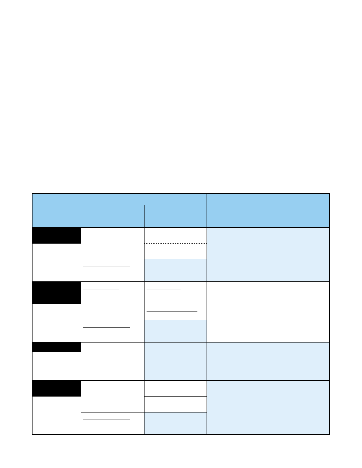
7 Application Setup
Before beginning configuration, consider how the controller will be used in your application. For instance,
how many control loops are needed, is cascade or ratio
control required, will the unit control a valve motor, do
you need setpoint profiling etc. Consideration should
also be given to the output types, alarms and tuning
method.
This section is intended to help with this process, guiding you through the major configuration settings. Additional information can be found in the relevant sections
of this manual, including the glossary, configuration
menus, and dedicated sections for major features.
These are listed in the table of contents.
Pre-Commissioning Considerations
An easy Setup Wizard is available for basic applications where the most commonly required parameters
are present for adjustment in turn. The wizard has a
sub-set of the full configuration menu options. For
Loop 1 / Master
Process Type*
(only if 2nd
input fitted)
One Loop*
Input 2 Configuration | Input
2 Usage = Not
Used
Two Loops*
Input 2 Configuration | Input 2
Usage = Standard
+Feedback*
Input 2 Configuration | Input 2
Usage = Feedback
Redundant*
Input 2 Configuration | Input 2
Usage = Feedback
Standard PID
Control Select
= Control Standard
Valve Motor Drive
Control Select
= VMD (TPSC) Control
Standard PID
Control Select
= Control Standard
Valve Motor Drive
Control Select = VMD
(TPSC) Control
Valve Motor Drive
Control Select
= VMD (TPSC) Control
Standard PID
Control Select
= Control Standard
Valve Motor Drive
Control Select = VMD
(TPSC) Control
Control
Configuration:
Control Select
Control
Configuration:
Control Type
Primary Only
Control Type = Single
Primary/Secondary
Control Type = Dual
Primary Only
Control Type = Single
Primary/Secondary
Control Type = Dual
Primary Only
Control Type = Single
Primary / Secondary
Control Type = Dual
more complex applications where the wizard is not
sufficient, consideration must be given to the following
fundamental questions:
If fitted, how will the 2nd input be used?
• One loop only (if the 2nd input not fitted or not used
in this application)
• Two independent control loops
• Valve feedback for loop 1
• A “redundant” backup for the 1st input
• Cascaded with the first control loop
• A reference input for ratio control
How will the instrument physically control the process?
• Primary only or primary & secondary control outputs
• Direct valve motor drive outputs
The table below shows the main input and control configuration settings for these application types (see configuration menus).
Loop 2 / Slave
Control
Configuration:
Control Select
Standard PID Control
Select = Control
Standard
Valve Motor Drive
Control Select = VMD
(TPSC) Control
Primary Only Control
Type = Single
Primary / Secondary
Control Type = Dual
Control
Configuration:
Control Type
21
Page 30
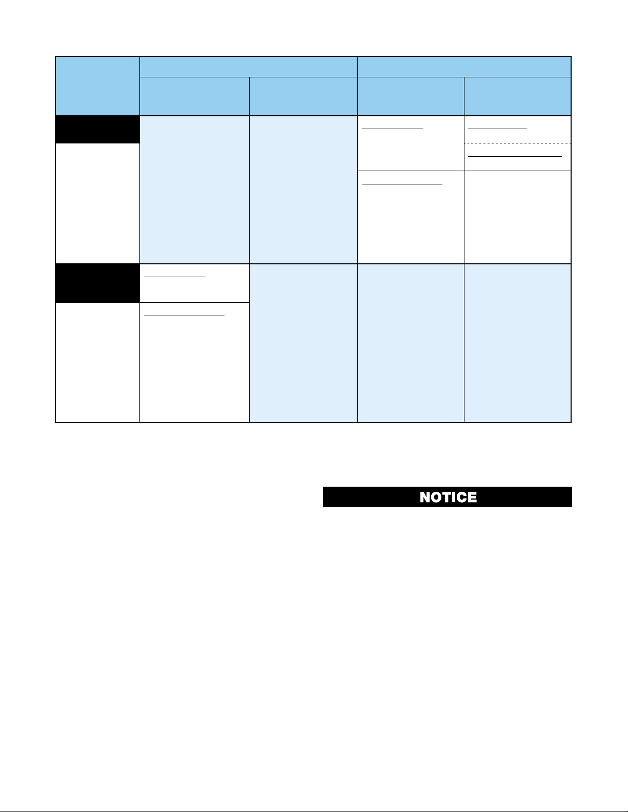
Loop 1 / Master
Loop 2 / Slave
Process Type*
(only if 2nd
input fitted)
Cascade*
Input 2 Configuration | Input 2
Usage
= Standard
AND
Loop 1 / Master
Configuration |
Control Mode =
Cascade
Ratio*
Input 2 Configuration | Input 2
Usage
= Standard
AND
Loop 1 / Master
Configuration |
Control Mode =
Ratio
Control
Configuration:
Control Select
Standard PID
Control Select
= Control Standard
Valve Motor Drive
Control Select
= VMD (TPSC) Control
Control
Configuration:
Control Type
Control
Configuration:
Control Select
Standard PID
Control Select
= Control Standard
Valve Motor Drive
Control Select = VMD
(TPSC) Control
Control
Configuration:
Control Type
Primary Only
Control Type = Single
Primary / Secondary
Control Type = Dual
Which outputs will be used for control, and are alarms
or event outputs needed?
• Output configuration
• Alarms & Profile Events
What are the sources for the setpoints?
• Local setpoint(s) only, or a remote setpoint input
• Profile Control
Is Input re-configuration required?
• Analogue input calibration & scaling
• Digital input functions
Which other features are to be used?
• Data Recorder.
• Serial Communications.
• USB Interface.
Once you have an understanding of your application
and how the controller will be used, continue on to the
configuration and use section below.
CAUTION: Configuration & commissioning must
be completed before proceeding to Operation
Mode. It is the responsibility of the installing
engineer to ensure that the configuration is
safe.
22
Page 31

8 Operation and Configuration Menus
This section contains information on all of the controller’s modes and the configuration menus.
Operation Mode
This is the mode used during normal operation of the
instrument. It can be accessed from the Main Menu,
and is the usual mode entered at power-up. The available displays are dependent upon the features/options
fitted and the way in which it has been configured.
The Base screen is the usual screen displayed during
operation. It provides “at a glance” information about
the process. The Profile Status screen shows similar
information when using profiles.
Subsequent screens allow the display and selection/
adjustment* of the setpoints. From display configuration, a selection of other parameter screens can be
made available for operator selection/adjustment*.
These include: profile control; cascade open/close;
auto/manual control; setpoint ramp rate; setpoint
source; control enable; clear latched outputs; data recording & status trend views. Optional operator mode
screens are marked in the screen lists. Some screens
will persist until the user navigates away, others will
‘time-out’ back to the base screen.
* If required, all Operation Mode parameters can be
made read only. Otherwise parameters such as setpoints can be adjusted within their configured limits.
Set all Configuration parameters as required
before starting normal operations. It is the responsibility of the installing engineer to ensure
that the configuration is safe for the intended
application.
Navigating and Adjusting Values in Operator Mode
Press to move forward or to move backwards
through the available screens.
When a displayed value can be adjusted, use
to change its value.
The next/previous screen follows the last parameter. If
no further changes are needed, hold down
for >1sec to skip straight to the next/previous screen
accepting ALL values shown.
In Trend Views, pressing or moves the cursor
line back and forward through the last 240 data points.
or
or
ELECTRIC SHOCK/FIRE HAZARD. DURING
NORMAL USE, THE USER MUST NOT REMOVE
THE CONTROLLER FROM ITS HOUSING OR
HAVE UNRESTRICTED ACCESS TO THE REAR
TERMINALS, AS THIS WOULD PROVIDE POTENTIAL CONTACT WITH HAZARDOUS LIVE
PARTS. FAILURE TO FOLLOW THESE INSTRUCTIONS COULD RESULT IN PERSONAL INJURY
OR DEATH AND/OR EQUIPMENT / PROPERTY
DAMAGE.
23
Page 32

OPERATION MODE SCREEN SEQUENCE
(scaled ±5% of input span)
±100% primary & secondary)
* = in loop 1 & 2 screen area
Master
All possible screens are listed below. The sequence shown depends on the configuration and status. E.g. settings for “Loop 2” only apply if 2nd input is fitted and configured for 2-loop control.
*Some screens are only shown if set to do so in Display Configuration.
After 2 minutes without key activity, the most screens revert to the Base Operating Screen. Screens marked
do not revert automatically. They remain displayed until the user navigates away.
Calibration Check Due Warning
If a Calibration Reminder is set and the due date has passed this will be shown at every power up, and repeated
once per day. Press to acknowledge and continue using the instrument temporarily without recalibration.
Change the due date or disable the reminder to cancel the warning. This feature is only possible if the recorder
is fitted. It is enabled in Input Configuration
Single Control Loop: Normal Operation
LED Indicators
LED Function Labels
Process Variable Value
Effective Actual Setpoint
Value
Engineering Units
Control Deviation Graph
Two Control Loops: Normal Operation
Power Graph (0-100% primary,
LED Indicators
LED Function Labels
Process Variable* & Actual
Setpoint Values*
Indicators for Alarm and
Remote Setpoint active*
Loop Description*
Control Deviation (±5% of
span) & Power Graphs* Engineering Units*
2-LOOP OPERATION
Default LED indicator functions are PRI, SEC, TUNE & ALARM - the functions and their labels can be altered only
with the PC configuration software.
In valve motor drive mode, the power bar-graph is replaced by valve Open / Stop / Close unless the 2nd input
is used for position feedback, where it shows 0 to 100% valve position.
In manual mode the effective setpoint is replaced by the %Manual Power and the label “MAN”.
In manual mode with valve motor drive the setpoint is replaced by valve Open / Stop / Close.
If control is disabled the effective setpoint value is replaced by “OFF”.
Cascade Control: Normal Operation
LED Indicators
LED Function Labels
Master Process Value
Cascade Status
Setpoint (Slave SP if
Slave Process Value
Cascade Open)
Control Deviation (±5% of
span) & Power Graphs
24
Page 33

OPERATION MODE SCREEN SEQUENCE
Ratio
RATIO CONTROL
Progres
d
1-LOOP PROFILE STATUS
Default LED indicator functions are PRI, SEC, TUNE & ALARM - the functions and their labels can be altered only
with the PC configuration software.
Cascade Status shows “Cascade” when cascade is operating normally and “Cascade Open” when the master
/ slave link has been disconnected. Master & Slave Process Values.
In valve motor drive mode, the power bar-graph is replaced by valve Open / Stop / Close.
In manual mode the slave setpoint is replaced by the %Manual Power and the label “MAN”.
In manual mode with valve motor drive the slave setpoint is replaced by valve Open / Stop / Close.
If control is disabled the effective master setpoint value is replaced by “OFF”.
Radio Control: Normal Operation
LED Indicators
LED Function Labels
Relative Process Value
& Setpoint Labels
Relative Setpoint
Control Deviation (±5% of
span) & Power Graphs
Default LED indicator functions are PRI, SEC, TUNE & ALARM - the functions and their labels can be altered only
with the PC configuration software.
In manual mode the ratio setpoint value is replaced by the %Manual Power and the label “MAN”.
If control is disabled the effective setpoint value is replaced by “OFF”.
Operator Profile Control
Allows the operator to control the defined profiles.
If a profile is running, the choices are: Do Nothing; Abort Profile (end immediately); Jump to Next Segment; Hold
Profile or Release Hold.
If no profile is running, the choices are: Do Nothing; Run Profile; End Profile Control (returns to standard controller operation) or Select Profile. *only shown if set to do so in Display Configuration.
Single Control Loop: Profiler Status
LED Indicators
LED Function Labels
Process Value & Setpoint
Engineering Units
Profile Name & Progress
Segment No, Type &
s(or Delayed Start
Time)
Default LED indicator functions are as shown in the initial base screen.
In manual mode the effective setpoint is replaced by the %Manual Power and the label “MAN”.
In manual mode with valve motor drive the setpoint is replaced by valve Open / Stop / Close.
If control is disabled the effective setpoint value is replaced by “OFF”.
Note: If power is lost when a profile is running and recovery is set to continue, the bar-graph re-starts
from the beginning but the overall time remains correct.
25
Profile Status Indicator:
Run,
Held,
■ Stoppe
Page 34

OPERATION MODE SCREEN SEQUENCE
* = in loop
Two Control Loops: Profiler Status
LED Indicators
LED Function Labels
Engineering Units*
Profile Status Indicators*:
Run, Held,
■ Stopped
Process Variable Values &
Setpoints*
Loop Descriptions*
Profile Name & Progress
1 & 2 screen area
Default LED indicator functions are as shown in the initial base screen.
In manual mode the effective setpoints are replaced by the %Manual Power and the label “MAN”.
In manual mode with valve motor drive the setpoints are replaced by valve Open / Stop / Close.
Note: If power is lost when a profile is running and recovery is set to continue, the bar-graph re-starts
from the beginning but the overall time remains correct.
Event Status
Cascade Mode
Auto/Manual Control Selection – Loop 1 (or Cascade Slave)
Setpoint Value Display &
Adjustment – Loop 1
Lists all configured profile events with their current status (Active or Inactive) –
Shown only when the instrument is in profiler mode.
Allows the user to open the cascade, breaking the master-slave link for commissioning & tuning.
CAUTION: Return to Cascade-CLOSE when finished!
*only shown if set to do so in Display Configuration.
Switches loop 1 (or the cascade slave loop) between automatic and manual
control modes. Switching between these modes uses “Bumpless Transfer”. *only
shown if set to do so in Display Configuration.
When using standard PID control, Manual mode replaces the Setpoint display with
a -100 to 100% power output level value, labelled “Man”. The
used to adjust the manual power value.
When using VMD control, Manual mode replaces the Setpoint display with the
valve movement status (Opening, Closing or Stopped), labelled “Man”. The
key opens the valve and the key closes the valve.
If Manual control is selected when in Cascade mode, the slave loops % power
value shown. This is the power output fed directly to the control actuator (e.g.
power to the heater elements).
CAUTION: Manual mode overrides the automatic control loop. It also
ignores any output power limits, valve open/close limits and the control enable/disable setting. The operator is responsible for maintaining the process within safe limits.
Note: If power is lost when a profile is running and recovery is set to continue,
the bar-graph re-starts from the beginning but the overall time remains correct.
View and adjust the main and alternate setpoints for loop 1 (or the master loop in
cascade mode). The setpoints can be set to any value within the setpoint limits set
in Control Configuration. View and adjust local (internal) setpoints for the loop. The
currently selected setpoint is marked as “active”. If the alternate setpoint is remote
it cannot be adjusted from the keypad.
2-LOOP PROFILE STATUS
Segment No. Type & Progress
(or Delayed Start Time)
or keys are
26
Page 35

OPERATION MODE SCREEN SEQUENCE
Setpoint Ramp Rate –
Loop 1
Select Active Setpoint –
Loop 1
Control Enable – Loop 1
Auto/Manual Control
Selection – Loop 2
The setpoint ramp rate adjustment for loop 1. Adjustable between 0.1 and 9999.0
display units per hour. When set to “OFF”, setpoint changes will step immediately
to the new value - *only shown if set to do so in Display.
Note: If power is lost when a profile is running and recovery is set to continue,
the bar-graph re-starts from the beginning but the overall time remains correct.
Select if the main or alternate setpoint is to be the “active” setpoint for loop 1 (or the
master loop in cascade mode). *only shown if set to do so in Display.
Enables or disables loop 1 control outputs. When disabled, the primary and secondary control outputs of loop 1 are set to zero 0% (unless manual mode has been
selected) and the setpoint value is replaced by “OFF”. *only shown if set to do so
in Display.
CAUTION: The instrument cannot control the process when disabled.
Switches loop 2 between automatic and manual control modes. Switching between
these modes uses “Bumpless Transfer”. *only shown if set to do so in Display Configuration. When using standard PID control, Manual mode replaces the Setpoint
display with a -100 to 100% power output level value, labelled “Man”. The
keys are used to adjust the manual power value.
When using VMD control, Manual mode replaces the Setpoint display with the valve
movement status (Opening, Closing or Stopped), labelled “Man”. The
the valve and the key closes the valve.
CAUTION: Manual mode overrides the automatic control loop. It also
ignores any output power limits, valve open/close limits and the control
enable/disable setting. The operator is responsible for maintaining the
process within safe limits.
key opens
or
Setpoint Value Display &
Adjustment – Loop 2
Setpoint Ramp Rate –
Loop 2
Select Active Setpoint –
Loop 2
Control Enable – Loop 2
Alarm Status
In manual mode a running profile will hold if it is controlling the setpoint of loop
2, until automatic control is reselected.
View and adjust the main and alternate setpoints for loop 2. The setpoints can be
set to any value within the setpoint limits set in Control Configuration. View and adjust local (internal) setpoints for the loop. The currently selected setpoint is marked
as “active”. If the alternate setpoint is remote it cannot be adjusted from the keypad.
The setpoint ramp rate adjustment for loop 2. Adjustable between 0.1 and 9999.0
display units per hour. When set to “OFF”, setpoint changes will step immediately
to the new value - *only shown if set to do so in Display.
If the setpoint ramp feature is used, it disables pre-tune completely, and if selftune is used, it will only calculate new terms after the ramp has completed and
the setpoint is constant.
Select if the main or alternate setpoint is to be the “active” setpoint for loop 2 (or the
master loop in cascade mode). *only shown if set to do so in Display
Enables or disables loop 2 control outputs. When disabled, the primary and secondary control outputs of loop 2 are set to zero 0% (unless manual mode has been
selected) and the setpoint value is replaced by “OFF”.
*only shown if set to do so in Display Configuration.
CAUTION: The instrument cannot control the process when disabled.
Lists the status of the alarms. Shown if any of the 7 alarms is active. The titles
“Alarm n” can be replaced with the PC configuration software to a user defined 8
character name for each alarm.
27
Page 36

OPERATION MODE SCREEN SEQUENCE
Manual Record Digital Input Profile Record Alarm Record
Active Alarm(s)
Trend Upper Scale Value
Loop No,
TREND VIEW
Clear Latched Outputs
Recorder Memory Full
Warning
Manual Recording
Trigger
Recorder Status
Information
Hold down or for 3 seconds to clear the selected latched output – An output
will only reset if the condition that caused it to latch on is no-longer present. *only
shown if set to do so in Display Configuration.
Indicates that the Data Recorder memory is full and that recording has either
stopped or is overwriting older data if in FIFO recording mode.
Set the manual recording trigger on or off. *only shown if set to do so in Display
Configuration.
Note: Setting the manual trigger to off may not stop the recording. Data recording will still take place if another recording trigger is active.
Shows the recording status (“Stopped” or “Recording”); icons for any active recording triggers; the recording mode (FIFO or Record Until Memory Is Used); the
approximate recording time remaining* and a memory usage bar-graph. In FIFO
mode, the time remaining is replaced with “FIFO” when full. *If the status of alarms is
recorded, extra samples are taken when the alarms change state reducing the available recording time. Take this into account when determining if there is sufficient
memory available.
Icons for Active Recored Triggers
Trend Views: One per COntrol Loop
Process Variable Trend
Setpoint Trend (dotted) Trend Lower Scale Value
& Time Markers
(10 samples per marker)
Cursor Line
PV Value At Cursor Line
Sample Interval (or time at
cursor line)
Trend views can be shown of each loop. They are auto-scaling graphs with alarm indication and other process
information. The trend can be set to show the process variable only; the process variable & setpoint (dotted
line), or the minimum and maximum value of the process variable measured since the last sample. Any active
alarm(s) are indicated above the graph. Graph types and data sample intervals 1 sec to 30 mins) are set in
Display Configuration. Trend scale values adjust automatically to visible data (between 2 to 100% of the input
span).
120 data points are visible. Pressing or moves the cursor line back through the graph to examine up to
240 data points. The process variable value of that data point is shown to the right of the cursor line and the
sample rate value is replaced by the time represented by the cursor position.
*only shown if set to do so in Display Configuration.
Note: Trend data is not retained at power down or if the sample interval is changed.
28
Page 37

OPERATION MODE SCREEN SEQUENCE
Custom Display Screens
You can copy up to 50 configuration menu parameters into normal operation mode
using the PC software. These extended operator mode screens appear at the end of
the normal sequence. If the parameter is normally displayed on screen with another
parameter, both parameters will appear.
Note: In this mode screens are not pass-code protected, they can be freely
adjust. It is possible to make operation mode “read only”, including any custom
screens from Display Configuration.
Main Menu
This menu is used to access the various features and
configuration settings. The available menus are dependent upon the features and options fitted and how it
has been configured.
Entry into the Main Menu
Holding down and pressing from Operation Mode
and most other screens will cause the unit to enter the
Main Menu. Each time this key press sequence is made,
the instrument moves to the next menu level above.
Sub-menu levels will require this sequence to be pressed
more than once in order to reach the Main Menu.
Navigating the Main Menu
Once in the Main Menu, press or to select the
required option
Press
Scrolling “Help Text” is shown at the bottom of the
screens to aid navigation.
to enter the chosen menu.
Unlock Codes
To prevent unauthorized entry, most menus require a
pass-code (1 to 9999) to gain entry. These menus are
indicated by the symbol
and changed from the Lock Code Configuration submenu of Configuration Mode. The factory default unlock code is 10 for all modes but for security, these
should be changed to new values. If the Configuration
Mode lock code is lost, refer to Lost Lock Codes.
. The codes can be viewed
Operation Mode
Setup Wizard
Supervisor Mode
Configuration Menu
Automatic Tuning
USB Menu
Recorder Control
Profile Setup
Profile Control
Service & Product
Information
OPERATION MODE SCREEN SEQUENCE
The normal operation screens, displaying the process and setpoint values; selection/adjustment of the setpoints; auto/manual control; alarm/event status;
trend views; data recorder and profile information.
An easy, step-by-step parameter setup for simple applications.
If configured from the PC software, a sub-set of up to 50 Configuration screens
can be accessed.
Accesses the sub-menus for Inputs; Control Loops; Outputs; Alarms; Communications; Recorder; Clock; Display and Lock Codes. There is an option to
Reset to Defaults wiping all user settings from the instrument.
Selection of Pre-tune, Self-tune and Auto Pre-tune for the control loops.
Uploading/downloading instrument configuration, profile information and data
recordings.
Manually starting, stopping and deleting recordings
Selection of profiles. Running, holding or aborting the selected profile
Selection of profiles. Running, holding or aborting the selected profile
Contact information for service/support, followed by instrument information,
including features and plug-in modules installed, serial number, firmware version etc.
29
Page 38

Setup Wizard
An easy Setup Wizard runs automatically at first ever
power-up. Follow the Wizard to setup parameters required for basic applications. The parameters covered
by the Setup Wizard are marked with a w in the following sections covering the configuration mode submenus. Once completed, the Setup Wizard exits to
Operation Mode.
The Wizard can be run again at any time from the Main
Menu. An option to reset all parameters to default (recommended) is offered when manually running the wizard.
Resetting defaults all parameters, not just
those covered by the quick setup wizard. For
more complex applications the user may have
to reconfigure other Configuration Menu settings before using the instrument.
Experts or users with more complex applications can
select the parameters they wish to setup directly from
the Configuration Menus bypassing the Wizard.
Manual entry to the Setup Wizard
To select the Setup Wizard from the Main Menu.
Hold down
Press or to select Setup Wizard.
Note: With the exception of the first ever power-up,
entry into this mode is security-protected by the
Setup Wizard Lock Code. Refer to the Lock Code
Configuration sub-menu.
Press to enter the Setup Wizard.
and press to enter the Main Menu.
Navigating in the Setup Wizard
Press to move forward, or to move backwards
through the screens.
Press or to change the value as required.
Holding down
immediately to the next/previous screen accepting ALL
values as shown.
Hold down and press to return to the Main Menu
Scrolling “Help Text” is shown at the bottom of the
screens to aid navigation.
or for more than 1 second skips
SETUP WIZARD SCREENS
Setup Wizard
Unlocking
Key Screens from
Configuration Menu
(those marked w)
Setup Wizard
Completed
Enter correct code number to access Setup Wizard.
w
Factory Default value is 10.
Press
w
screen prompts to alter the values.
w
Confirms completion of the Setup Wizard. Exits to Operation Mode.
to select each major configuration parameter in turn. Follow on-
Supervisor Mode
This mode is only available if it has been configured
from the PC software. Its purpose is to allow selected
operators access to a lock-code protected sub-set of
the configuration parameters, without providing them
with the higher level configuration menu unlock code.
The PC software can copy up to 50 parameters from
configuration menus for inclusion in the supervisor
mode screen sequence. If the parameter is normally
displayed on screen with another parameter, both parameters will appear. It is not possible to configure supervisor mode screens without using the software.
Entry into Supervisor Mode
Adjustments to these parameters should only
be performed by personnel competent and authorized to do so.
Supervisor Mode is entered from the Main Menu
Hold down
Press or to select Supervisor Mode
and press to enter the Main Menu.
Note: Entry into this mode is security-protected by
the Supervisor Mode Lock Code. Refer to the Lock
Code Configuration sub-menu.
30
Page 39

Press to enter the Supervisor Mode.
Navigating in the Supervisor Mode
Press to move forward, or to move backwards
through the screens.
Press or to change the value as required.
SUPERVISOR MODE SCREENS
Supervisor Mode
Unlocking
Supervisor Mode
Screens
If Supervisor Mode is configured, enter correct code number to continue.
Factory Default value is 10.
Press
to alter the values.
to select each selected parameter in turn. Follow on-screen prompts
The next/previous screen follows the last parameter. If
no further changes are required, hold down or
>1sec to skip straight to next/previous screen accepting ALL values shown..
Hold down and press to return to the Main Menu
Scrolling “Help Text” is shown at the bottom of the
screens to aid navigation.
Configuration Menu
This menu can be used as an alternative to the more
limited Setup Wizard when the instrument is configured for the first time in more complex applications, or
when further changes are required to the instruments
settings. The configuration menu contains a number
of sub-menus that allow access to all of the available
parameters. The correct settings must be made before attempting to use the instrument in an application.
Screens marked w are also shown in the Setup Wizard.
Entry into the Configuration Menu
Adjustments to these parameters should only
be performed by personnel competent and authorized to do so.
Configuration is entered from the Main Menu
Hold down and press to enter the Main Menu.
Press or to select Configuration Menu
Note: Entry into this mode is security-protected by
the Configuration Menu Lock Code. Refer to the
Unlock Code section for more details.
Configuration contains sub-menus to set-up the Inputs; Control; Outputs; Alarms; Communications; Recorder; Clock; Display and Lock Codes.
There is also an option to reset the instrument to its
factory default settings.
The Input and Control sub-menus contain further submenus with configuration and
calibration settings for each process input; control
loops 1 & 2 and the digital inputs. Only parameters that
are applicable to the hardware and options fitted will
be displayed.
From the Configuration Menu, press or to select the required sub-menu.
Press to enter the sub-menu.
If required, press or to select the next level sub-
menu, then press to enter.
Hold down
menu level.
Scrolling “Help Text” is shown at the bottom of the
screens to aid navigation.
and press to return to next higher
Press to enter the Configuration Menu.
Navigating the Configuration Menu
CONFIGURATION MENU SCREENS
Configuration Mode
Unlocking
Configuration Options
Enter correct code number to access Configuration Mode. Factory Default
value is 10.
Select the required Configuration Sub-Menu Option from: Inputs; Control;
Outputs; Alarm; Communications; Recorder; Clock; Display; Lock Code or
Reset To Defaults.
31
Page 40

CONFIGURATION MENU SCREENS
Input 1 Setup - Sub-menu to setup Input 1. Press + to return to Input Menu
Input Type
Engineering Units
Decimal Point Position
Scaled Input Lower
Limit
Scaled Input Upper
Limit
Multi-Point Scaling
Enable
Scaling Point n
Display Value n
CJC Enable/Disable
Input Filter Time
Select from various Thermocouple, RTD and Linear mA, mV or VDC inputs. -
w
see specifications section for available input types.
Note: Recheck the units and decimal point settings if you change the
input type.
Select display units from: °C; °F; °K; bar; %; %RH; pH; psi or none. Tempera-
w
ture sensor inputs are limited to °C; °F
Sets the maximum display resolution to 0; 1; 2 or 3 decimal places. Numbers
>99.999 never display more than 2 dec places, >999.99 never display more
w
than 1 dec place and >99999 always display without a decimal place. Temperature inputs are limited to 0 or 1 decimal place.
For temperature inputs, upper & lower limits set the usable span. The minimum
span = 100 units, maximum span = range limits for the sensor type selected.
For DC linear inputs, the limits define the values shown (-9999 to 9999.9) when
input is at minimum and maximum values. Min span = 100 units.
Enables or disables multi-point scaling. This allows up to 15 point input linearization for DC signals - not possible with temperature sensor inputs
If multi-point scaling is enabled, up to 15 breakpoints* can scale input vs. displayed values between the scaled input limits. Each breakpoint has a % value
for the input signal, and the value to display when the input is at that value. *A
Scaling Point set to 100% input ends the scaling sequence.
Enables/disables internal thermocouple Cold Junction Compensation. If disabled, external compensation will be required for thermocouples. The default
value is Enabled.
Removes unwanted signal noise. Adjustable from 0.1 to 100.0 seconds or OFF
(default = 2s). Use the smallest value that gives acceptable results.
Caution: Large values slow the response to changes in the process.
Input 1 Calibration - Sub-menu to calibrate Input 1. Press
Calibration Type
Calibration Offset
Calibration Low Value
Calibration Low Offset
Calibration High Value
Calibration High Offset
Input 2 Setup - Sub-menu to calibrate Input 2. Press
Select the calibration type from base; single or 2-point calibration. Select single to apply a calibration offset across the entire measured range. Use 2-point
to enter calibration offsets at both low and high points of the usable range –
refer to User Calibration details.
Caution: The default is Base Calibration. For single or 2-point cali-
bration, the user must enter values to adjust the displayed value to
match a known standard or accurate external reading.
The single point calibration offset. Limited by the input span, +Ve values add
to, –Ve values subtract from, the measured input across entire range.
The displayed value for the 1st (low) adjustment of 2-point calibration. Choose
a value close to the lowest level used in the application.
The adjustment value for the 1st (low) point when using 2-point calibration.
+Ve values add to, –Ve values subtract from measured input at this point.
The displayed value for the 2nd (high) adjustment of 2 point calibration. Choose
a value close to the highest level used in the application.
The adjustment value for the 2nd (high) point when using 2-point calibration.
+Ve values add to, –Ve values subtract from measured input at this point.
+
+
to return to Input Menu
to return to Input Menu
32
Page 41

Input 2 Usage
Input Type
Engineering Units
Decimal Point Position
Scaled Input Lower
Limit
Scaled Input Upper
Limit
Multi-Point Scaling
Enable
Scaling Point n
Display Value n
CJC Enable/Disable
Input Filter Time
Set Valve Lower Position
Set Valve Upper Position
CONFIGURATION MENU SCREENS
Input 2 can be used as a standard process input for a second control loop
(including its use as part of a cascade), a redundant input or a feedback signal
w
input from a valve or flow meter. Redundant or Feedback disables the input as
an independent control loop.
w
If input 2 is selected as a standard process input, select from various Thermocouple, RTD and Linear mA, mV or VDC inputs. - see specifications section on
page 245, for available input types.
If input 2 is selected as feedback possible types are limited to Linear mA, mV,
VDC or Potentiometer.
Redundant inputs automatically assume the same input type as input 1.
Note: Recheck the units and decimal point settings if you change the
input type.
Select display units from: °C; °F; °K; bar; %; %RH; pH; psi or none. Tempera-
w
ture sensor inputs are limited to °C; °F
Sets the maximum display resolution to 0; 1; 2 or 3 decimal places. Numbers
>99.999 never display more than 2 dec places, >999.99 never display more
w
than 1 dec place and >99999 always display without a decimal place. Temperature inputs are limited to 0 or 1 decimal place.
For temperature inputs, upper & lower limits set the usable span. The minimum span = 100 units, maximum span = range limits for the sensor type
selected - see specs on page 245. For DC linear inputs, the limits define the
values shown (-9999 to 9999.9) when input is at minimum and maximum values. Min span = 100 units.
Enables or disables multi-point scaling. This allows up to 15 point input linearization for DC signals - not possible with temperature sensor inputs
If multi-point scaling is enabled, up to 15 breakpoints* can scale input vs. displayed values between the scaled input limits. Each breakpoint has a % value
for the input signal, and the value to display when the input is at that value. *A
Scaling Point set to 100% input ends the scaling sequence.
Enables/disables internal thermocouple Cold Junction Compensation. If disabled, external compensation will be required for thermocouples. The default
value is Enabled.
Removes unwanted signal noise. Adjustable from 0.1 to 100.0 seconds or OFF
(default = 2s). Use the smallest value that gives acceptable results.
Caution: Large values slow the response to changes in the process.
If input 2 is selected as feedback indication, this stores the feedback value
equal to the minimum valve travel. The procedure below moves the valve to
the fully closed position to find the feedback value:
Press
Press until the valve is closed to its limit of its travel.
Press and simultaneously to store the feedback level.
If input 2 is selected as feedback indication, this stores the feedback value
equal to the maximum valve travel. The procedure below moves the valve to
the fully open position to find the feedback value:
Press
Press U until the valve is opened to its limit of its travel.
Press and simultaneously to store the feedback level.
and simultaneously to begin feedback limit adjustment.
and simultaneously to begin feedback limit adjustment.
Input 2 Calibration - Sub-menu to calibrate Input 2. Press
33
+
to return to Input Menu
Page 42

Calibration Type
Calibration Offset
Calibration Low Value
Calibration Low Offset
Calibration High Value
Calibration High Offset
CONFIGURATION MENU SCREENS
If input 2 is selected as a standard process input, the user can select the calibration type from base; single or 2-point calibration. Select single to apply a
calibration offset across the entire measured range. Use 2-point to enter calibration offsets at both low and high points of the usable range – refer to the
User Calibration details.
Caution: The default is Base Calibration. For single or 2-point cali-
bration, the user must enter values to adjust the displayed value to
match a known standard or accurate external reading.
The single point calibration offset. Limited by the input span, +Ve values add
to, –Ve values subtract from measured input across the range.
The displayed value for the 1st (low) adjustment of 2-point calibration. Choose
a value close to the lowest level used in the application.
The adjustment value for the 1st (low) point when using 2-point calibration.
+Ve values add to, –Ve values subtract from measured input at this point.
The displayed value for the 2nd (high) adjustment of 2 point calibration. Choose
a value close to the highest level used in the application.
The adjustment value for the 2nd (high) point when using 2-point calibration.
+Ve values add to, –Ve values subtract from measured input at this point.
Calibration Reminder - Calibration reminder Sub-menu. Press
Calibration Reminder
Enable/Disable
Calibration Reminder
Date
Auxiliary Input A Setup - Sub-menu to setup auxiliary A input. Press
Auxiliary Input A Type
Aux A Input Lower Limit
Aux A Input Upper Limit
Auxiliary Input A Offset
Enables/disables the Calibration Reminder shown at start-up (and daily thereafter), if the due date has passed - Recorder version only
Sets the due date for Calibration Reminder - Recorder version only.
Enables/disables the Calibration Reminder shown at start-up (and daily thereafter), if the due date has passed - Recorder version only
These scale values relate to when auxiliary input A is at the range minimum
& maximum values. They are adjustable between ±0.001 & ±10000. When
auxiliary input A provides a remote setpoint, the scaled input becomes the effective setpoint (although always constrained within setpoint limits).
Caution: Take care to scale correctly especially if being used as
the remote setpoint source for both loops.
An offset applied to the scaled auxiliary input A value. Adjustable, from +/-
0.001 to 20000 units or OFF, with. +Ve values add, –Ve values subtracted.
Useful in multi-zone setpoint slave applications. Default = OFF.
+
to return to Input Menu
to return to Input Menu
+
34
Page 43

CONFIGURATION MENU SCREENS
Digital Input Setup - Sub-menu to setup the Digital Inputs. Press + to return to Input Menu
Digital Input Status
Tick Digital Inputs To
Invert
Profile Selection Type
Choose Profile Selection
Configure Digital Inputs
Soft Digital Input n
Digital Input Logic
Soft Digital Input n
Alarm-Event
Digital Input n Function
A diagnostic status (
c = OFF, R = ON, Ø = not available) for digital inputs A;
C1 to C8 and “Soft “digital inputs S1 to S4. If used for profile selection, it also
shows bit pattern type (binary or BCD) and selected profile number
Select digitals input with R to invert their operation (making them appear OFF
when their actual state is ON). Inputs shown as Ø are not available.
Select the bit pattern to be used for profile selection. Binary or BCD (Binary
Coded Decimal). Select None if profile selection not is required.
For profiler versions, the Multi-Digital Input option can be used to select the
profile to run with a standard binary bit pattern or binary coded decimal from
BCD switches. C1 is the least significant bit (LSB) of the bit pattern. Profiles
are numbered from 0 to 63. Use the table to choose inputs C1 to Cn for the
number of profiles to select:
C1 C1 to C2 C1 to C3 C1 to C4 C1 to C5 C1 to C6 C1 to C7
Binary 0 to 1 0 to 3 0 to 7 0 to 15 0 to 31 0 to 63
BCD 0 to 1 0 to 3 0 to 7 0 to 9 0 to 19 0 to 39 0 to 63
Any inputs chosen for profile selection are not available for other uses.
– refer to Digital Inputs
Select any available digital input or soft digital input to be configured for use.
The current status of each is shown as Assigned or Unused.
Set up a “Soft” digital input n that is the result of the Boolean AND selections
of physical inputs, globally OR’d with the OR selections.
Press
or to select R / deselect c the options. Inputs shown as Ø are
not available – refer to Digital Inputs
Further set up of “Soft” digital input n that adds the Boolean OR of Alarms &
Events to the physical digital inputs already selected.
Press
or to select R / deselect c the options. Inputs shown as Ø are
not available – refer to Digital Inputs
Select the function to be operated from digital input n. – The possible functions are:
Loop 1 or 2 Setpoint Select; Loop 1 or 2 Auto/Manual Select; Loop 1 or 2 Control Select; Loop 1 or 2 Pre-Tune Select; Loop 1 or 2 Self-Tune Select
Clear All Latched Outputs; Output n Clear Latch; Output n Forcing On or Off;
Profile Run/Hold; Profile Hold Segment Release; Profile Abort; Data Recorder
Trigger or Key n Mimic (replicating pressing
or ).
35
Page 44

CONTROL CONFIGURATION SUB-MENU SCREENS
Control Loop 1 - Sub-menu to setup Control Loop 1. Press + to return to Input Menu
These settings apply to the master loop if the controller has been setup for cascade control.
Control Mode
Cascade Mode
Profile Selection Type
Control Select
Control Enable/Disable
Auto/Manual Control
Selection
Control Type
Primary Control Action
Control Status
Power Output Levels
Gain Schedule PID Set
in Use
Select the fundamental application type, from: Standard; Cascade or Ratio.
Refer to the Application Setup section.
Note: Choosing Cascade or Ratio disables the use of the 2nd input as a
fully independent control loop.
Opens or closes the cascade link. Cascade-Open breaks the master-slave
connection. This allows slave loop to be tuned & adjusted independently.
Caution: Return to Cascade when finished!
Select the bit pattern to be used for profile selection. Binary or BCD (Binary
Coded Decimal). Select None if profile selection not is required.
Select from Control Standard or Control VMD (TPSC).
Use Control VMD to directly drive the windings of a motorized valve. This uses
a 3-point stepping algorithm giving “open” and “close” outputs.
Use Standard for all other applications (including solenoid valves or modulating valves with positioning circuitry requiring mA or VDC signals).
Used to temporarily disable the control outputs. Select control Enabled (normal) or Disabled – when disabled, control output(s) for this loop are turned off
(unless manual mode has been selected), and the setpoint value is replaced
by “OFF”.
Caution: The instrument is not able to control the process when
control is disabled and the Output Power Limits are ignored.
Switches the control loop between Automatic and Manual Control. The operator monitors and alters power to correctly control the process (0 to 100% or
-100 to +100% for dual control).
Caution: Manual mode overrides the automatic control loop. It
also ignores any output power limits, valve open/close limits and
the control enable/disable setting. The operator is responsible for
maintaining the process within safe limits.
Select Single Control for primary control only (e.g. heating only or cooling only)
or Dual for primary and secondary control outputs (e.g. heating and cooling) Dual is not possible with Ratio or VMD Control.
Set the primary control output for Reverse or Direct Action. Reverse action applies additional primary power as the process falls further below setpoint (e.g.
heating applications).
Direct action applies additional primary power as the process rises higher
above setpoint (e.g. cooling applications).
In dual control, secondary output action is opposite to primary action.
A “read-only” diagnostic status display of the current loop 1 process variable
and effective setpoint values to assist with manual tuning.
A “read-only” diagnostic status display of the current loop 1 primary and secondary % output power levels to assist with manual tuning – Not shown with
VMD Control. Does not apply if control is disabled or in manual mode.
A “read-only” diagnostic status display showing the PID set in use. The set
used may vary based on the current setpoint or process variable value. – Only
shown if Gain Scheduling is in use.
36
Page 45

PID Set Selection
Set n – Primary Pb
Set n – Secondary Pb
Set n – Integral
Set n – Derivative
Set n – Overlap
Set n – On/Off Diff
Set n - Breakpoint
Manual Reset (Bias)
Anti Wind-Up Limit
Ratio SFAC
Ratio NO
Primary Cycle Time
Secondary Cycle Time
CONTROL CONFIGURATION SUB-MENU SCREENS
Choose to use one of five PID Sets; or choose Gain Schedule on SP or PV. –
This selects a fixed PID set to be “Active”; or automatically switch sets based
changes in SP or PV values.
The primary proportional band for PID Set n (n = up to 5). Set as On-Off control, or a proportional band from 1 to 9999 display units – Only the set(s) in use
are shown.
The secondary proportional band for PID Set n (n = up to 5) if dual control is
used. Set as On-Off control, or a proportional band from 1 to 9999 display
units – Only the set(s) in use are shown.
The integral time value (Automatic Reset) for PID Set n (n = up to 5). Adjustable
from 1s to 99min 59s or OFF – Only the set(s) in use shown.
The derivative time value (Rate) for PID Set n (n = up to 5). Adjustable from 1s
to 99 min 59s or OFF – Only the set(s) in use are shown.
The overlap (+ve) or deadband (-ve) between primary & secondary proportional bands for PID Set n (n = up to 5). In display units - limited to 20% of the
combined primary & secondary prop band width.
The on-off control hysteresis (deadband) for PID Set n (n = up to 5). Adjustable
from 1 to 300 display units, centred about the setpoint – Only the set(s) in use
are shown.
The SP or PV value where the PID Set n (n = up to 5) if gain scheduling is used.
Set 1 is used from Scaled Input Lower Limit to the Set 2 Breakpoint, then Set
2 used to the Set 3 Breakpoint etc. If a breakpoint is set to OFF subsequent
PID sets are not used. The final PID set runs to the Scaled Input Upper Limit.
The Manual Reset value to bias the control working point within the proportional band(s). Adjustable from 0 to 100% for single control or 100 to +100%
for dual control. Typically set to 80% of typical power needed for setpoint, but
lower values can help inhibit start-up overshoot.
Adjusts the value at which the “reset wind-up inhibit” is applied. Above this
power level further integral action is suspended. Adjustable from 10 to 100%
of PID power. Lower values inhibit overshoot.
Caution: If set too low control deviation can occur (the process set-
tles, but is offset above or below the setpoint). It this is observed,
increase the value until the deviation error is removed.
The nominal ratio scaling factor used for Stoichiometric Ratio Control in burner fuel/air control applications. Adjustable from 0.010 to 99.999. – refer to the
Ratio Control section.
A constant between 0.0 & 9999.0, added to the x1 (input 1) value in Stoichiometric Ratio Control mode to allow for atomizing air when calculating the process value. The total air flow is therefore x1 + NO
The primary power cycle time. Adjustable from 0.5 to 512 seconds. Applied for
time proportioned primary relay, SSR driver or triac control outputs – Not used
for VMD Control modes.
The secondary power cycle time when dual control is used. Adjustable from
0.5 to 512 seconds. Applied for time proportioned primary relay, SSR driver or
triac control outputs – Not used for VMD Control modes.
37
Page 46

CONTROL CONFIGURATION SUB-MENU SCREENS
Primary Power Lower
Limit
Primary Power Upper
Limit
Secondary Power Lower
Limit
Secondary Power Upper
Limit
Sensor Break Pre-set
Power Output
Motor Travel Time
Minimum Motor On
Time
Valve Open Limit
Valve Close Limit
Valve Sensor Break
Action
The minimum primary output power limit. The control algorithm will not allow
the power output fall below this level. Adjustable from 0 to 90% but is always
at least 10% below the primary power upper limit.
Caution: The instrument will not be able to control the process
correctly if the lower limit is above the level required to maintain
setpoint.
The maximum primary output power limit. The control algorithm will not allow
the power output rise above this level. Adjustable from 10 to 100% but is always at least 10% above the primary power lower limit.
Caution: The instrument will not be able to control the process
correctly if the upper limit is below the level required to maintain
setpoint.
The minimum secondary output power limit. The control algorithm will not
allow the power output fall below this level. Adjustable from 0 to 90% but is
always at least 10% below the secondary power upper limit.
Caution: The instrument will not be able to control the process
correctly if the lower limit is above the level required to maintain
setpoint.
The maximum secondary output power limit. The control algorithm will not allow the power output rise above this level. Adjustable from 10 to 100% but is
always at least 10% above the secondary power lower limit.
Caution: The instrument will not be able to control the process
correctly if the upper limit is below the level required to maintain
setpoint.
Set the power level to be applied if the process input signal or an active remote
setpoint input is lost. Adjustable from 0 to 100% for single control or -100 to
+100% for dual control. The default value is OFF (0% power). Does not apply
if control is disabled or in manual mode.
Caution: Ensure the value set will maintain safe process condi-
tions.
The motor travel time (valve movement time from fully open to fully closed in
mm:ss). Adjustable from 5s to 5 mins - In VMD Control Mode only.
The minimum drive effort (in seconds) to begin moving the motorized valve
in VMD Control Mode. Adjustable from 0.02 to 1/10 of the Motor Travel Time
The maximum position the controller will attempt to drive the valve to in VMD
Control Mode. Adjustable from the valve close limit+1% to 100.0% (fully open)
- Only possible if the 2nd input is used for valve feedback.
The minimum position the controller will attempt to drive the valve to in VMD
Control Mode. Adjustable from 0.0% (fully closed) to the valve open limit-1%
- Only possible if the 2nd input is used for valve feedback.
The direction to drive the valve if the process input signal or an active remote
setpoint input is lost. The default action is to drive the valve closed. – Applies
to VMD Control Mode only. Does not apply if control is disabled or in manual
mode.
Caution: Set to safe values for the process!
38
Page 47

CONTROL CONFIGURATION SUB-MENU SCREENS
Setpoint Lower Limit
Setpoint Upper Limit
Setpoint Ramp Rate
Main Setpoint Source
Alternate Setpoint
Source
Main Setpoint Value
Alternate Setpoint Value
Select Active Setpoint
Main Setpoint Offset
Alternate Setpoint
Offset
The minimum allowable setpoint value. Adjustable within the scaled input limits, but cannot be above the setpoint upper limit. Applies to local, remote and
profile setpoints.
Caution: Set to safe values for the process. Operators can adjust
local setpoints to any value between the limits set.
The maximum allowable setpoint value. Adjustable within the scaled input limits, but cannot be below the setpoint lower limit. Applies to local, remote and
profile setpoints.
Caution: Set to safe values for the process. Operators can adjust
local setpoints to any value between the limits set.
Setpoint Ramp Rate value, adjustable from 1 to 9999 display units per hour, or
OFF. The ramp is applied at power-up (from current PV to SP) and whenever
the setpoint value or source is changed. If set to OFF, the setpoint steps immediately to the new setpoint value.
Select the source of the main setpoint. This can only be a “Local” setpoint set
from the keypad, or Not used.
Select the source of the alternate setpoint. This can be a “Local” setpoint, not
used, or an analogue remote setpoint (RSP) signal applied to input 2 or auxiliary input A – depending on available hardware.
Sets the current value of the main setpoint between the setpoint upper and
lower limits.
Sets the current value of the alternate setpoint between the setpoint upper
and lower limits – is read-only if alternate setpoint source is RSP.
Select if the main or alternate setpoint is to be the current “active” setpoint for
this loop.
An offset that can be added to the main setpoint (+ve values) or subtracted
from it (-ve values) when the instrument is a comms slave in a multi-zone application. This changes the effective setpoint used for control.
Caution: It should be set to zero if an offset is not required.
An offset that can be added to the alternate setpoint (+ve values) or subtracted
from it (-ve values) when the instrument is a comms slave in a multi-zone application. This changes the effective setpoint used for control.
Caution: It should be set to zero if an offset is not required.
Control Loop 2 - Sub-menu to setup Control Loop 1. Press + to return to Input Menu
These settings apply to the slave loop if the controller has been setup for cascade control.
Control Select
Control Enable/Disable
Select from Control Standard or Control VMD (TPSC).
Use Control VMD to directly drive the windings of a motorized valve. This uses
a 3-point stepping algorithm giving “open” and “close” outputs.
Use Standard for all other applications (including solenoid valves or modulating valves with positioning circuitry requiring mA or VDC signals).
Used to temporarily disable the control outputs. Select control Enabled (normal) or Disabled – when disabled, control output(s) for this loop are turned off
(unless manual mode has been selected) and the setpoint value is replaced
by “OFF”.
Caution: The instrument is not able to control the process when
control is disabled and the Output Power Limits are ignored.
39
Page 48

Auto/Manual Control
Selection
Control Type
Primary Control
Action
Control Status
Power Output Levels
Gain Schedule PID
Set in use
PID Set Selection
Set n – Primary Pb
Set n – Secondary Pb
Set n – Integral
Set n – Derivative
Set n – Overlap
Set n - Breakpoint
Manual Reset (Bias)
Anti Wind-Up Limit
Switches the control loop between Automatic and Manual Control.
Caution: Manual mode overrides the automatic control loop. It
also ignores any output power limits, valve open/close limits and
the control enable/disable setting. The operator is responsible for
maintaining the process within safe limits.
Select Single Control for primary control only (e.g. heating only or cooling
only) or Dual for primary and secondary control outputs (e.g. heating and
cooling) - Dual is not possible with Ratio or VMD Control.
Set the primary control output for Reverse or Direct Action. Reverse action
applies additional primary power as the process falls further below setpoint
(e.g. heating applications). Direct action applies additional primary power as
the process rises higher above setpoint (e.g. cooling applications). In dual
control, secondary output action is opposite to primary action.
A “read-only” diagnostic status display of the current loop 2 process variable and effective setpoint values to assist with manual tuning.
A “read-only” diagnostic status display of the current loop 2 primary and
secondary % output power levels to assist with manual tuning – Not shown
with VMD Control. Does not apply if control is disabled or in manual mode.
A “read-only” diagnostic status display showing the PID set in use. The set
use may vary based on the current setpoint or process variable value. – Only
shown if Gain Scheduling is in use.
Choose to use one of five PID Sets; or choose Gain Schedule on SP or PV.
– This selects a fixed PID set to be “Active”; or automatically switch sets
based changes in SP or PV values.
The primary proportional band for PID Set n (n = up to 5). Set as On-Off
control, or a proportional band from 1 to 9999 display units – Only the set(s)
in use are shown.
The secondary proportional band for PID Set n (n = up to 5) if dual control is
used. Set as On-Off control, or a proportional band from 1 to 9999 display
units – Only the set(s) in use are shown.
The integral time value (Automatic Reset) for PID Set n (n = up to 5). Adjustable from 1s to 99min 59s or OFF – Only the set(s) in use are shown.
The derivative time value (Rate) for PID Set n (n = up to 5). Adjustable from
1s to 99 min 59s or OFF – Only the set(s) in use are shown.
The overlap (+ve) or deadband (-ve) between primary & secondary proportional bands for PID Set n (n = up to 5). In display units - limited to 20% of
the combined primary & secondary prop band width.
The SP or PV value where the PID Set n (n = up to 5) if gain scheduling is
used. Set 1 is used from Scaled Input Lower Limit to the Set 2 Breakpoint,
then Set 2 used to the Set 3 Breakpoint etc. If a breakpoint is set to OFF
subsequent PID sets are not used. The final PID set runs to the Scaled Input
Upper Limit.
The Manual Reset value to bias the control working point within the proportional band(s). Adjustable from 0 to 100% for single control or 100 to +100%
for dual control. Typically set to 80% of typical power needed for setpoint,
but lower values can help inhibit start-up overshoot.
Adjusts the value at which the “reset wind-up inhibit” is applied. Above this
power level further integral action is suspended. Adjustable from 10 to 100%
of PID power. Lower values inhibit overshoot.
Caution: If set too low control deviation can occur (the process
settles, but is offset above or below the setpoint). It this is observed, increase the value until the deviation error is removed.
40
Page 49

Primary Cycle Time
Secondary Cycle Time
Primary Power Lower
Limit
Primary Power Upper
Limit
Secondary Power Lower
Limit
Secondary Power Upper
Limit
Sensor Break Pre-set
Power Output
Motor Travel Time
Minimum Motor On Time
Slave SP Scale Min
Slave SP Scale Max
Valve Sensor Break
Action
The primary power cycle time. Adjustable from 0.5 to 512 seconds. Applied
for time proportioned primary relay, SSR driver or triac control outputs – Not
used for VMD Control modes.
The secondary power cycle time when dual control is used. Adjustable from
0.5 to 512 seconds. Applied for time proportioned primary relay, SSR driver
or triac control outputs – Not used for VMD Control modes.
The minimum primary output power limit. The control algorithm will not allow the power output fall below this level. Adjustable from 0 to 90% but is
always at least 10% below the primary power upper limit.
Caution: The instrument will not be able to control the process
correctly if the lower limit is above the level required to maintain
setpoint.
The maximum primary output power limit. The control algorithm will not allow the power output rise above this level. Adjustable from 10 to 100% but
is always at least 10% above the primary power lower limit.
Caution: The instrument will not be able to control the process
correctly if the upper limit is above the level required to maintain
setpoint.
The minimum secondary output power limit. The control algorithm will not
allow the power output fall below this level. Adjustable from 0 to 90% but is
always at least 10% below the primary power upper limit.
Caution: The instrument will not be able to control the process
correctly if the lower limit is above the level required to maintain
setpoint.
The maximum secondary output power limit. The control algorithm will not
allow the power output rise above this level. Adjustable from 10 to 100% but
is always at least 10% above the primary power lower limit.
Caution: The instrument will not be able to control the process
correctly if the upper limit is above the level required to maintain
setpoint.
Set the power level to be applied if the process input signal or an active
remote setpoint input is lost. Adjustable from 0 to 100% for single control or
-100 to +100% for dual control. The default value is OFF (0% power). Does
not apply if control is disabled or in manual mode.
Caution: Ensure the value set will maintain safe process condi-
tions.
The motor travel time (valve movement time from fully open to fully closed in
mm:ss). Adjustable from 5s to 5 mins - In VMD Control Mode only.
The minimum drive effort (in seconds) to begin moving the motorized valve
in VMD Control Mode. Adjustable from 0.02 to 1/10 of the Motor Travel
Time.
The effective cascade slave setpoint value equating to 0% power demand
from the master controller - Limited by the slave input scaling.
Caution: Set to safe values for the process!
The effective cascade slave setpoint value equating to 100% power demand
from the master controller - Limited by the slave input scaling.
Caution: Set to safe values for the process!
The direction to drive the valve if the process input signal or an active
remote setpoint input is lost. The default action is to drive the valve closed. –
Applies to VMD Control Mode only. Does not apply if control is disabled or in
manual mode.
Caution: Set to safe values for the process!
41
Page 50

Setpoint Lower Limit
Setpoint Upper Limit
Setpoint Ramp Rate
Main Setpoint Source
Alternate Setpoint
Source
Main Setpoint Value
Alternate Setpoint Value
Select Active Setpoint
Main Setpoint Offset
Alternate Setpoint Offset
The minimum allowable setpoint value. Adjustable within the scaled input
limits, but cannot be above the setpoint upper limit. Applies to local, remote
and profile setpoints.
Caution: Set to safe values for the process. Operators can adjust
local setpoints to any value between the limits set.
The maximum allowable setpoint value. Adjustable within the scaled input
limits, but cannot be below the setpoint lower limit. Applies to local, remote
and profile setpoints.
Caution: Set to safe values for the process. Operators can adjust
local setpoints to any value between the limits set.
Setpoint Ramp Rate value, adjustable from 1 to 9999 display units per
hour, or OFF. The ramp is applied at power-up (from current PV to SP) and
whenever the setpoint value or source is changed. If set to OFF, the setpoint
steps immediately to the new setpoint value.
Select the source of the main setpoint. This can only be a “Local” setpoint
set from the keypad, or Not used.
Select the source of the alternate setpoint. This can be a “Local” setpoint,
not used, or an analogue remote setpoint signal applied to input 2 or auxiliary input A – depending on available hardware.
Sets the current value of the main setpoint between the setpoint upper and
lower limits.
Sets the current value of the alternate setpoint between the setpoint upper
and lower limits.
Select if the main or alternate setpoint is to be the “active” setpoint for this
loop.
An offset that can be added to the main setpoint (+ve values) or subtracted
from it (-ve values) when the instrument is a comms slave in a multi-zone application. This changes the effective setpoint used for control.
Caution: It should be set to zero if an offset is not required.
An offset that can be added to the alternate setpoint (+ve values) or subtracted from it (-ve values) when the instrument is a comms slave in a multizone application. This changes the effective setpoint used for control.
Caution: It should be set to zero if an offset is not required.
OUTPUTS CONFIGURATION SUB-MENU SCREENS
Output n Configuration - Up to 9 outputs listed. Any already used show as “Assigned” but can be changed.
If “Digital” is shown, the output is driven directly via a digital input (see input configuration). Relevant screen
sequences repeat for outputs fitted. Press
Linear Output n Type
Adjustable 0-10V
Transmitter PSU n
Output n Usage
OPn OR Selection
Set the desired type for any linear outputs fitted. From: 0-5, 0-10, 1-5, 2-10V
w
& 0-20, 4-20mA or 0-10VDC adjustable transmitter PSU.
Sets the voltage required if linear output n type is 0-10VDC adjustable trans-
w
mitter PSU.
Sets the use for the output. From: Loop 1 or 2 Primary / Secondary Power;
Logical OR or AND of Alarms & Profile Events (direct or reverse acting); Re-
w
transmission (of loop 1 or 2 effective setpoint, Input 1 or 2 process values).
Choices offered are appropriate for the output type fitted (e.g. only linear outputs can retransmit).
When an output usage is set for logical OR alarms & profile events, this selects
the alarms or events to be OR’d. Press
w
Alarms 1 to 7; Events 1 to 5; PR (Profile running); PE (Profile Ended). Direct
outputs turn on, & reverse outputs turn off according to the selected logical
OR combination.
+ to return to Configuration Menu
or to select R or deselect c
42
Page 51

OUTPUTS CONFIGURATION SUB-MENU SCREENS
OPn AND Selection
Output n Latch Enable
Output n Lower
Retransmit Limit
Output n Upper
Retransmit Limit
When an output usage is set for logical AND alarms & profile events, this selects the alarms or events to be AND’d. Press
c
w
Alarms 1 to 7; Events 1 to 5; PR (Profile running); PE (Profile Ended). Direct
outputs turn on, & reverse outputs turn off according to the selected logical
AND combination.
If enabled, an output will remain latched ON even if the condition that caused
it to be on is no-longer present, and remains latched even if the instrument is
powered off-on. The output latch must be reset to turn it off.
w
Note: An output cannot reset if the condition that caused it to turn on is
still present.
The displayed value at which the retransmission output reaches its minimum
level (e.g the display value when a 4 to 20mA retransmission output is at 4mA).
Adjustable from -9999 to 9999.9. The output is at its minimum below this
value. Above this value, it rises linearly in line with the displayed value to reach
its maximum at the Upper Retransmit Limit display value.
w
The displayed value at which a retransmission output will be at its maximum
level (e.g. the display value when a 4 to 20mA retransmission output is at
20mA). Adjustable from -9999 to 9999.9. The output is at its maximum above
this display value. Below this value, it falls linearly in line with the displayed
value to reach its minimum at the Lower Retransmit Limit display value.
or to select R or deselect
ALARM CONFIGURATION SUB-MENU SCREENS
Alarm n Configuration - 7 alarms listed with any already used shown as “Assigned”. Relevant screen se-
quences repeat for each alarm (n = 1 to 7). Press
+ to return to Configuration Menu
Alarm n Type
Alarm n Source
Alarm n Value
Alarm n Hysteresis
Alarm n Minimum
Duration
Alarm n Inhibit
Sets the function of alarm n from: Unused; Process High; Process Low; PV-SP
Deviation; Band; Control Loop; Rate Of Signal Change per minute; Input Sig-
w
nal Break; % of Recorder Memory Used, Control Power High, Control Power
Low.
The signal source of Alarm n from: Input 1, Input 2 & Auxiliary Input A; Control
Loop 1; Control Loop 2; Loop 1 Primary or Secondary Power; Loop 2 Primary
w
or Secondary Power – auxiliary input A is only possible if fitted and the alarm
type can only be input signal break.
The Alarm n activation point – The value is limited by the scaled input limits for
Process High; Process Low; PV-SP Deviation (+ve above, -ve below setpoint),
Band (above or below setpoint) type alarms. Rate of Signal Change is a rate
of 0.0 to 99999 (rate in units per minute). Memory used, Control Power High,
Control Power Low are 0.0 to 100.0% – not required for Control Loop or Input
w
Signal Break alarm types.
The deadband on the “safe” side of alarm n, through which signal must pass
before alarm deactivates - not for Rate of Change, Control Loop, Input Break
or Percentage of Memory used alarms.
The minimum time that alarm n must be passed its threshold before activating
(deactivation is not affected by this parameter). Adjustable from 0.0 to 9999.0
secs. – not used for signal break, memory or loop alarms.
w
Caution: If the duration is less than the time set, the alarm will not
become active.
If the inhibit is enabled, it prevents the initial alarm activation if the alarm con-
w
dition is true at power up. Activation only occurs once the alarm condition has
passed and then reoccurred
43
Page 52

Control n Loop Alarm
Manual Record Digital Input Profile Record Alarm Record
Type
Control n Loop Alarm
Time
COMMUNICATIONS CONFIGURATION SUB-MENU SCREENS
No Communications
Warning
Modbus Parity
Modbus Data Rate
Master Mode, or Slave
Address
Target Register In Slave
Master Mode Format
Serial Communications
Write Enable
ALARM CONFIGURATION SUB-MENU SCREENS
Sets the loop alarm time source, from: Manual Loop Alarm Time (as set in the
loop alarm n time screen) or Automatic (twice the integral time constant set-
w
ting). If configured, a Loop Alarm activates if no response is seen in loop n after
this time following the saturation of its power output. – Only seen if an alarm is
set for control loop type.
The time (max 99:59 mm:ss) for loop n to begin responding after PID power
w
output reaches saturation, if a manual loop alarm type is configured.
If Communications Configuration menu is entered without a communications
module fitted.
The setting for Modbus comms parity bit checking, from: Odd; Even or None.
Set the same parity for all devices on the network – Only seen if RS485 or
Ethernet communications option is fitted.
The setting for the Modbus comms data speed. From: 4800; 9600; 19200;
38400; 57600 or 115200 bps. Set the same speed for all devices on the network – Only seen if RS485 or Ethernet communications option is fitted.
Slave address (1 to 255), or multi-zone Setpoint Master Mode – Only seen if
RS485 or Ethernet communications option is fitted, but Master mode is not
available over Ethernet.
Target memory register for the setpoint value in attached slave controllers. All
slaves must have the same setpoint register address as set here - Appears
only if unit is in Master mode.
The data format required by the attached setpoint slaves. From: Integer; integer with 1 decimal place or float - Appears only if unit is in Master mode.
Enables/disables writing via RS485 or Ethernet communications. When disabled, parameters can be read, but attempts to change their values over comms are blocked.
DATA RECORDER CONFIGURATION SUB-MENU SCREENS:
No Recorder Warning
Recording In Progress
Warning
Pause (Override Trigger)
Recorder Status
Information
If the Recorder Configuration menu is entered on an instrument without this
option fitted.
A warning if recording when attempting to enter recorder configuration.
Access to the configuration is denied unless the recording is paused.
Select No to continue recording or Yes to enter recorder configuration.
Note: Recording is paused until recorder configuration is completed. It
restarts automatically on exit from this menu.
Current information about the data recorder feature, including if a recording is
in progress (Recording or Stopped); the recording mode (FIFO or Record Until
Memory Is Used); a % memory use bar-graph and the estimated available time
remaining based on the data selected and memory left. If the alarm status is
recorded and is likely to change often, take this into account when determining if there is sufficient memory available.
Icons are displayed for active recording triggers. If any trigger is active, the
selected data will be recorded.
44
Page 53

DATA RECORDER CONFIGURATION SUB-MENU SCREENS:
Recorder Mode
Recording Sample
Interval
Choose Record Until Memory Used (stops recording when full) or Continuous
FIFO (First In - First Out).
Caution: A FIFO recording will overwrite previous recordings in
memory, starting with the oldest data first. Download the previous
data before selecting this option.
Recording of the selected data will happen once every sample interval. From
every: 1; 2; 5; 10; 15; 30 Seconds, or 1; 2; 5; 10; 15; 30 Minutes.
- The recording interval does not affect Trend View sample rates.
Note: Shorter intervals reduce the possible recording duration.
Recorder Auto Trigger
Trigger on Alarms
Loop 1 Values to Record
Loop 2 Values to Record
Other Values to Record
Activities to Record
Automatic recording triggers. From: None; On Alarm; During Profile and Alarm
or Profile. Data is recorded if any trigger is active (including a digital input or
manual recording start).
Any combination of alarms 1 to 7 can be set to trigger a recording (TRG) or
not (OFF). If any alarm set to TRG becomes active, the alarm recording trigger
activates.
Note: 10 samples at 1s intervals are stored and added to the recording
prior to and after the data that is stored at the normal sample rate while
the alarm is on.
Any combination of loop 1 values can be recorded from: Process Variable;
Maximum or Minimum PV (since the previous sample was taken); Setpoint;
Primary Power, Secondary Power. Set to Record (REC) or not (OFF).
Note: Recording more parameters reduces the possible
recording duration.
Any combination of loop 2 values can be recorded from: Process Variable;
Maximum or Minimum PV (since the previous sample was taken); Setpoint;
Primary Power, Secondary Power. Set to Record (REC) or not (OFF).
Note: Recording more parameters reduces the possible
recording duration.
If required, select to record the value of auxiliary input A.
Multiple process events can be recorded from: Alarm n Status (n = 1 to 7) or
Unit turned Off/On.
Profiler Events to
Record
Note: If an alarm changes state an extra sample is recorded using extra
memory. The remaining recording time is reduced accordingly.
The Profiler Event n Status can be recorded (n = 1 to 5).
Note: If a profile event changes state an extra sample is recorded using
extra memory. The remaining recording time is reduced accordingly.
45
Page 54

Date Format
Set Date
Set Time
Note: Clock settings cannot be changed when the data recorder is active.
DISPLAY CONFIGURATION SUB-MENU SCREENS
Language
Enable Custom Display
Mode
Read Only Operation
Mode?
Display Color
Invert Display
Display Contrast
Loop 1 Trend Sample
Interval
Loop 1 Trend View Mode
Loop 2 Trend Sample
Interval
Loop 2 Trend View Mode
Operator Visibility
CLOCK CONFIGURATION SUB-MENU SCREENS
The format used for all displayed dates: dd/mm/yyyy (Day / Month / Year) or
w
mm/dd/yyyy (Month / Day / Year). – Recorder versions only.
Set the internal clock Date – Entered in the format defined by Date Format
w
screen. – Recorder versions only.
Set the internal clock Time. - In hh:mm:ss (Hours : Minutes : Seconds) format.
w
– Recorder versions only.
Select English or the alternate local language. The alternate language is selected at time of order, but can be changed later using the PC software.
Enables/disables the Custom Operation Mode, if configured. The screens
seen in this mode are configured using the PC configuration software.
Allows Operation Mode to be Read/Write or Read-Only where screens can be
seen but the values cannot be changed.
From: Red only; Green only; Red to Green on Alarm or Green to Red on Alarm;
Red to Green if Output Latched or Green to Red if Output Latched.
Standard or Inverted display image.
Screen contrast (10 and 100) to improve clarity. 100 = maximum contrast.
The Interval between the displayed values on the loop 1 trend graph. From:
Every 1; 2; 5; 10; 15; 30 Seconds, or 1; 2; 5; 10; 15; 30 Minutes. -
Independent from the loop 2 trend graph and data recorder sample rates.
The data to display on the loop 1 trend graph. From: Process Value only, PV
(solid) & SP (dotted) at sample time, or the Max & Min PV between samples
(candle-stick graph). Alarm active indication is always shown at the top of
graph.
The Interval between the displayed values on the loop 2 trend graph. From:
Every 1; 2; 5; 10; 15; 30 Seconds, or 1; 2; 5; 10; 15; 30 Minutes. - Independent
from the loop 1 trend graph and data recorder sample rates.
The data to display on the loop 1 trend graph. From: Process Value only, PV
(solid) & SP (dotted) at sample time, or the Max & Min PV between samples
(candle-stick graph). Alarm active indication is always shown at the top of
graph.
Extra parameters can be made visible/adjustable in Operation Mode from:
Profile Control; Recorder Start/Stop; Recorder Status; Loop 1 & 2 Setpoint
Select; Loop 1 & 2 Auto/Manual Select; Loop 1 & 2 Control Select; Loop 1 & 2
Trend View; Loop 1 & 2 Setpoint Ramp Rate.
See Operator Mode lists.
46
Page 55

Lock Code
Configuration
Reset To Defaults
LOCK CODE CONFIGURATION SUB-MENU SCREEN
Set Lock Codes (passwords) for the following configuration and control
menus: Setup Wizard; Configuration Mode; Tuning Menu; Supervisor Mode;
USB Menu; Recorder Menu, Profiler Setup and Profiler Menu. Independently
adjustable from 1-9999 or OFF.
Note: The factory default value is 10 for all lock codes. For
security, users are recommended to change these codes.
RESET TO DEFAULTS SUB-MENU SCREEN
The user can set all parameters back to their factory default values before
preparing the instrument for installation in a new application.
Caution: The user must reconfigure all of the required settings be-
fore using the instrument.
The USB Menu
A notification is shown if a USB memory stick is inserted or removed from the USB port. The USB Menu
will automatically be offered after insertion. The USB
menu can also be accessed from the Main Menu.Entry
into the Configuration Menu.
Entry into the USB Menu
Do not remove the memory stick from the USB
port whilst a Data Transfer to or from the USB
stick is in progress. Data loss or corruption
may result.
The USB Menu is entered from the Main Menu
Hold down
Press or to select USB Menu
Note: Entry into this mode is security-protected by
the USB Menu Lock Code. Refer to the Lock Code
Configuration sub-menu.
and press to enter the Main Menu.
Navigating the USB Menu
Press to move forward, or to move backwards
through the screens.
Press or to change the value as required.
The next/previous screen follows the last parameter. If
no further changes are required, hold down or
>1sec to skip straight to next/previous screen accepting ALL values shown.
Hold down and press to return to the Main Menu
Note: During Data Transfer, normal operation carries on in the background, but operator access to
other screens is not possible. The transfer of a full
memory can take up to 20 minutes. Only begin a
transfer when you are certain that access (e.g. setpoint changes) will not be required.
Scrolling “Help Text” is shown at the bottom of the
screens to aid navigation.
Press to enter the Configuration Menu.
47
Page 56

USB Mode Unlocking
Read/Write To USB
Device
USB MENU SCREENS
Enter correct code number to access the USB Menu.
Factory Default value is 10.
Select the required action from: Read Configuration File; Write Configuration
File; Write Recorder Log File. Read Profile Files; Write Profile Files.
Note: “Writing” is downloading from the Instrument to the USB stick.
“Reading” is uploading from the USB stick to the Instrument.
Select Profile To
Write
Enter A File Name
Enter A Folder
Name
Write
Writing Profile,
Configuration or
Log
Transfer Successful
Transfer Failure
Select File
Reading Profile or
Configuration File
Read
Transfer Successful
Transfer Failure
If writing a profile to the USB memory stick, choose a profile to write from the
list provided.
Enter an 8-character file name if writing configurations or profiles. A file extension is automatically added to the end of file name (bct for configurations
or pfl for profiles).
Caution: Existing files with the same name will be over-written.
Recorder logs can contain multiple files. The user enters an 8-character folder
name for these logs. See the Data Recorder section
Note: To prevent existing recordings being over-written, an error message
is shown if the folder name entered already exists.
An animated screen is shown the files are being written.
Caution: Do not disconnect USB device until completed! Data loss
or corruption may result.
Confirmation that the data transfer to the USB stick completed correctly.
Press
For write failures, check for adequate disk space on the USB stick.
Select the Configuration or Profile file to transfer from the USB stick. Cau-
tion: Configuration reads overwrite ALL of the instruments exist-
ing settings with new values.
An animated screen is shown while files are being read. Caution: Do not
remove the memory stick whist this operation is in progress. Data
corruption may result.
Confirmation that the data transfer from the USB stick completed correctly.
Press
For read failures, check the maximum number of profiles and/or segments is
not being exceeded.
to continue
to continue.
48
Page 57

Recorder Control Menu
Manual Record Digital Input Profile Record Alarm Record
This menu allows the user to manually start a recording
or to delete previous recordings. Refer to the Recorder
Configuration sub-menu in Configuration Mode for information about how to setup the data to be recorded
and the recording interval and the Data Recorder Option section on page 97 for general information about
the recorder feature.
Entry into the Recorder Control Menu
The Recorder Control Menu is entered from the Main
Menu
Hold down and press to enter the Main Menu.
Navigating the Recorder Control Menu
Press to move forward, or to move backwards
through parameters & screens.
Holding down
immediately to the next/previous screen accepting
ALL values as shown.
Press or to select or change the value as required.
The next/previous screen follows the last parameter. If
no further changes are required, hold down or
>1sec to skip straight to next/previous screen accepting ALL values shown.
or for more than 1 second skips
Press or to select Recorder Control Menu
Note: Entry into this mode is security-protected by
the Recorder Control Menu Lock Code. Refer to the
Lock Code Configuration sub-menu.
Press
Recorder Mode
Unlocking
Recording in Progress
Warning
Start/Stop Data
Recording
to enter the Recorder Control Menu.
RECORDER MENU SCREENS:
Enter correct code number to access the Data Recorder Menu.
Factory Default value is 10.
Shown if a recording is in progress when the recorder control menu is entered.
Turn on or off the manual recording trigger.
Note: Recording continues if another record trigger is active (e.g. on
alarm/profile or via a digital input). Access is restricted to this screen
only until recording stops (remove all active triggers).
Hold down
Scrolling “Help Text” is shown at the bottom of the
screens to aid navigation.
and press to return to the Main Menu
Recorder Status
Information
Clear Recordings
Current information about the data recorder feature, including if a recording is
in progress (Recording or Stopped); the recording mode (FIFO or Record Until
Memory Is Used); a % memory use bar-graph and the estimated available time
remaining based on the data selected and memory left. If the alarm status is
recorded and is likely to change often, take this into account when determining
if there is sufficient memory available.
Icons are displayed for active recording triggers. If any are active, the selected
data will be recorded.
Clears the recorder memory. Download any recorded data before use.
Caution: This permanently deletes All recorded data.
49
Page 58

Profiler Setup Menu
Screens marked
must be completed for a valid profile to be created.
Refer to the Profiler section on page 87 for more details
about the profiler.
will not time-out automatically. They
Entry into the Profiler Setup Menu
The Profiler Setup Menu is entered from the Main Menu
Hold down and press to enter the Main Menu.
Press or to select the Profiler Setup Menu
Note: Entry into this mode is security-protected
by the profiler setup menu lock code. Refer to the
Lock Code Configuration sub-menu.
Navigating the Profiler Setup Menu
Press to move forward, or to move backwards
through parameters & screens.
Press or to select or change the value as required.
Holding down
immediately to the next/previous screen accepting
ALL values as shown.
Hold down and press to return to the Main Menu
Scrolling “Help Text” is shown at the bottom of the
screens to aid navigation.
or for more than 1 second skips
Press
Profiler Setup Menu
Unlocking
Profile Setup Options
General Profile
Configuration
to enter the Profiler Setup Menu.
Enable Edit While
Running
Timer Start
Function
General
PROFILER SETUP MENU SCREENS
Enter correct code number to access Profiler Setup Menu. Factory Default
value is 10.
Select the required profile setup sub-menu option from: General Configuration; Create a Profile; Edit a Profile Header; Edit a Profile Segment; Insert a
Segment; Delete a Segment; Delete a Profile or Delete ALL Profiles.
Sub-menu with global settings affecting all profiles. Press Press
return to Profile Setup Menu
Enables or disables the ability to edit profiles whist a profile is running.
Caution: Edits made to the current or next segment of the running
profile will take effect until after the profile is restarted.
Enable or disable automatic starting of profiles. When enabled, delayed starts
are possible, or if the selected profile has a day & time trigger it waits until the
time set before starting.
Note: If the Timer Start Function is disabled, profiles can only be manually
started, and with immediate effect even if they have a delay or day & time
trigger defined.
& to
Create A Profile
Sub-menu to create a new profile. A header is created first, followed by the
segments – see below.
Caution: It is not possible to exit from this sub-menu until profile
creation is fully complete. Do not turn off the power during profile creation or editing. When the profile creation/editing is complete the instrument returns automatically to the profile setup main
menu.
Note: A warning is displayed if the maximum number of 64 profiles or 255
segments is exceeded.
50
Page 59

PROFILER SETUP MENU SCREENS
Profile Header: Settings that apply to the chosen profile as a whole.
Enter Profile Name
Set the Number of
Loops
Give each profile a unique descriptive name of up to 16 characters. The name
is shown in the profile status screen and in profile selection lists.
Select if a profile controls the setpoint of first loop only or both control loops.
This screen is “read only” when editing a profile. The number cannot be
changed once the profile has been created.
Note: the segment type and time settings are common to both loops.
Some segment types are not available with 2-loop profiling
Profile Starting
Point
Profile Start Trigger
Profile Start Time
Profile Start Day(s)
Profile Header Details
Profile Start Delay
Time
Profile Recovery
Method
Profile Recovery
Time
Profile Abort Action
Profile Cycles
Profile Segments: Settings that apply to individual profile segments
Segment Number
Segment Type
Profile Segment Details
The setpoint value used at the beginning of the first segment. From: Current
Setpoint or Current Process Variable. The setpoint starts from the measured
PV(s) or effective setpoint(s) of the process as it begins running.
From: None (profile start is not delayed); After Delay or Day and Time.
- Day and Time possible on the recorder version only.
Note: If the Timer Start Function is disabled, profiles can only be manually
started, and with immediate effect even if they have a delay or day & time
trigger defined.
If Day and Time is the Profile Start Trigger, this is the time (hh:mm:ss) when
the profile will begin if it is selected to run.
If Day and Time is the Profile Start Trigger, this is the Day(s) when the profile
should run. From: Mon; Tue; Wed; Thu; Fri; Sat; Sun; Mon-Fri; Mon-Sat; SatSun or All.
If After Delay is the Profile Start Trigger, this is the delay time of up to 99:59
(hh:mm) before a profile begins after a start request has been given.
The power-on action if profile was running at power-down (e.g. after a power
cut), or following correction of a signal break. From: Control outputs off; Restart profile from the beginning; Maintain last profile setpoint; Use controller
setpoint; Continue profile from where it was when power failed..
The Recovery Method is ignored (the profile continues from where power
failed), if power off for less than this time. Max 99:59 (hh:mm).
- Recorder version only.
The action taken after profile has been forced to stop early. From: Control
outputs off; Maintain last profile setpoint or Use controller setpoint.
The number of times the program should run each time it is started. From 1 to
9999 or Infinite.
Shows the number of the profile segment being created. The maximum number of profiles across all profiles is 255.
Set the segment type from: Ramp Time (time to reach target SP); Ramp Rate
(rate of change towards target SP – Single loop profiles only); Step (jump to
target SP), Dwell (keep current SP); Hold (hold profile until released); Loop
(back to previous segment); Join (to another profile); End or Repeat Sequence
Then End (repeat a sequence of joined profiles).
Note: Segment Ramp Rate is not available if the profile controls two loops.
A Join, End or Repeat Sequence Then End isthe last segment in the profile. Repeat Sequence Then End is always the last profile in a sequence.
51
Page 60

Loop 1 Target
Setpoint.
Loop 2 Target
Setpoint.
Segment Ramp
Time
Segment Ramp
Rate
Segment Dwell
Time
Number of Loops
Back to Segment
Number
PROFILER SETUP MENU SCREENS
The setpoint value to be reached control loop 1 by the end of this segment, if
the type is Ramp Time, Ramp Rate or Step.
If the profile is controlling 2 loops, this is the setpoint value to be reached
control loop 2 by the end of the segment, if the type is Ramp Time or Step.
The time (hh:mm:ss) to reach the segment target setpoint if the segment type
is Ramp Time.
The rate of change towards the Segment Target Setpoint if segment type is
Ramp Rate. The rate can be from 0.001 to 9999.9 display units per hour.
The time (hh:mm:ss) to maintain the current setpoint if the segment type is
Dwell.
If the segment type is Loop, enter the number of times to repeat the loop
back, before continuing forward to the next segment.
If the segment type is Loop, enter the segment to loop back to.
Note: Two Loop-backs cannot be set to cross each other.
Loop 1 Auto-Hold
Type
Loop 1 Auto-Hold
Band Value
Loop 2 Auto-Hold
Type
Profile Segment Details
Loop 2 Auto-Hold
Band Value
Segment Hold
Release Type
Hold Release Time
Times To Repeat
Sequence
Segment End Type
Select Profile
to Join
The auto-hold type for this segment to ensure loop 1 tracks the setpoint.
From: None (no auto-hold); Above Setpoint (hold if too high only); Below Setpoint (hold if too low only) or Band (hold if too high or low).
The distance loop 1 can be from setpoint. Beyond this the profile is held for
the selected Auto-Hold Type.
Note: For Two-Loop Profiles, either loop can cause the profile to hold. The
profile continues only when both loops are within their Auto-Hold Bands.
The auto-hold type for this segment to ensure loop 2 tracks the setpoint.
From: None (no auto-hold); Above Setpoint (hold if too high only); Below Setpoint (hold if too low only) or Band (hold if too high or low).
The distance loop 2 can be from setpoint. Beyond this the profile is held for
the selected Auto-Hold Type.
Note: For Two-Loop Profiles, either loop can cause the profile to hold. The
profile continues only when both loops are within their Auto-Hold Bands.
A hold segment can either be released by an Operator/Digital input or be set
to wait until a specified Time of Day - Recorder version only.
The time of day (hh:mm:ss) when a Hold Segment will release if the Release
Type is Time Of Day. The profile is held by the hold segment and only released at the next occurrence of the time of day set.
The number of times the entire sequence of profiles should run. – if the last
segment is Repeat Sequence Then End.
The action taken after the profile ends normally. From: Control Outputs Off;
Maintain Last Profile Setpoint or Use Controller Setpoint.
Choose a profile to join to from the list provided – if the final segment type is
Join. The selected profile will start immediately the current profile ends.
52
Page 61

Event n
Profile Segment Details
Edit A Profile Header
Edit A Profile Segment
PROFILER SETUP MENU SCREENS
Select the events to be active during this segment. n = 1 to 5.
Note: For end segments, the events selected to be active stay on until the
instrument exits from profiler mode or a new profile runs.
Note: For end segments, the events selected to be active stay on until the
instrument exits from profiler mode or a new profile runs.
Choose the profile to be edited from the list of names provided, then alter
any values as required – The profile header details are as shown in “Create A
Profile” above.
Choose the profile, then the segment to be edited from the lists provided.
Alter any values as required – The profile segment details are as shown in
“Create A Profile” above.
Note: The last segment type can only be set to Join, End or Repeat Sequence Then End. Use Insert or Delete to change the end position.
Insert A Segment
Delete A Segment
Delete A Profile
Delete All Profiles
Profiler Control Menu
Profiler Control Menu
Unlocking
Profile Control
Select Profile
Choose the profile, then the new segment’s position from the lists provided –
Enter the new segment values as required – The profile segment details are as
shown in “Create A Profile” above.
Note: The new segment type cannot be set to Join, End or Repeat Sequence Then End. Use Delete to change the end position.
Choose the profile, then the segment to be deleted from the lists provided.
End, Join or Repeat segments cannot be deleted.
Choose the profile to be deleted from the list of names is provided. The user
is prompted confirm the deletion.
If selected, the user is prompted to confirm that the profiles should be deleted.
Caution: This deletes all profiles from memory!
PROFILER CONTROL MENU SCREENS
Enter correct code number to access Profiler Control Menu.
Factory Default value is 10.
If a profile is running, from: Do Nothing; Abort Profile (end immediately); or
Jump to Next Profile Segment; Hold Profile or Release Hold. If profile not
running, from: Do Nothing; Run Profile; End Profile Control (return to normal
controller operation) or Select Profile.
Selects a profile. If Run Profile was chosen in the previous screen, the profile
starts (after a delay if one is enabled). Otherwise the profile is selected, but
waits for a run instruction (e.g. via digital input or timer).
Note: Selection is “read only” if profile selection is via a digital input.
Otherwise choose from the list of profile names provided.
53
Page 62

Service & Product Information Mode
This is read only information about the instrument, its
modules and enabled features. It has contact information to tell the user where they can obtain service, sales
or technical support for the product. Normally this is
the manufacturer or suppliers’ details. Using the PC
software, the user can enter their own contact information. There are 7 lines of text - each up to 25 characters
in length.
Entry into Service & Product Information
Mode
The Service & Product Information Mode is entered
from the Main Menu
Hold down and press to enter the Main Menu.
Press or to select the Service & Product Information Mode.
Navigating Product Information Mode
Press to move forward or to move backwards
through the displayed information.
Hold down
Scrolling “Help Text” is shown at the bottom of the
screens to aid navigation.
and press to return to the Main Menu
Press
Mode.
Plug-in Module
Information
Base Options
Optional Features
Firmware Information
Product Revision Level
Serial Number
Date of Manufacture
Input 1 Calibration
Status
Input 2 Calibration
Status
Calibration Check
Due Date
For Service Contact
to enter the Service & Product Information
SERVICE & PRODUCT INFORMATION SCREENS:
Lists the type plug-in modules types in Slots 1, 2, 3 or A
Lists factory fitted base options, from: 2nd Universal/Aux input; Output 4 & 5
Relay; Output 6 & 7 Linear mA/V DC.
Lists which other optional features are fitted/enabled, from: Profiler; USB
Port; Data Recorder and 8 Digital Inputs.
The type and version of firmware installed in the instrument.
Software and Hardware update status.
The instrument serial number.
The instrument Date of Manufacture (date format is dd/mm/yyyy).
The base calibration status for each signal type on input 1.
Caution: Re-calibrate input 1 for mVDC, VDC, mADC, RTD or Ther-
mocouple CJC if they do not say “Calibrated”
The base calibration status for each signal type on optional input 2.
Caution: Re-calibrate input 2 for mVDC, VDC, mADC, RTD or Ther-
mocouple CJC if they do not say “Calibrated”
The date re-calibration is due. – only shown if the Calibration Reminder is
enabled in the Input Configuration menu.
Contact information for service, sales or technical support.
54
Page 63

Automatic Tuning Menu
The automatic tune menu is used to engage pre-tune
and/or self-tune to assist setting up proportional bands
and the integral and derivative time values used by the
control loops.
Pre-tune can be used to set PID parameters approximately. Self-tune may then be used to optimize the tuning if required. See the Tuning section on page 99 for
more information. Pre-tune can be set to run automatically after every power-up by enabling Auto Pre-Tune.
Entry into the Automatic Tuning Menu
The Automatic Tuning Menu is entered from the Main
Menu
Hold down and press to enter the Main Menu.
Press or to select the Automatic Tuning Menu.
Press R to enter the Automatic Tuning Menu.
AUTOMATIC TUNING MENU SCREENS
Automatic Tuning Mode
Unlocking
Control loop 1 or 2
Cascade Mode
Enter correct code number to access the Automatic Tuning Menu. Factory
Default value is 10.
Select which control loop you want to tune –if unit has 2 control loops.
To pre-tune a cascade slave, select open-cascade.
Note: When slave tuning is completed, repeat choosing open-cascade to
tune the master.
Navigating the Automatic Tuning Menu
Press to move forward or to move backwards
through the selections.
Press or to change values or engage and disengage the tuning as required.
Hold down
Scrolling “Help Text” is shown at the bottom of the
screens to aid navigation.
and press to return to the Main Menu
Pre-Tune Method
Pre-Tune Value
Pre-Tune Save Location
Run Pre-Tune on Set n
Now?
Pre-Tune Status
Engage Self-Tune
Self-Tune Status
From: Pre-Tune Standard or Pre-Tune at Value. Standard Pre-Tune tests the
process response half-way from the activation point to the setpoint. Pre-Tune
at Valve allows the user to specify where the test occurs.
Sets the value at which the process is tested for Pre-Tune at Valve.
Caution: Consider possible over-shoot!
Store the pre-tune result to one of 5 PID sets. The new PID terms can be
stored to any set, without changing the “active set” from control configuration.
Turns pre-tune on/off for the chosen PID Set. If configured, the TUNE LED
w
indicator flashes whilst pre-tune is operating - *see below.
Note: Pre-tune is disabled in on-off control mode; if the PV is less than 5%
of span from setpoint; during Profiles; if the setpoint is ramping or if the
selected control loop has been disabled.
Shows the current pre-tune status: Running or Stopped. If an attempt to run
pre-tune failed, the reason is shown.
Turns self-tune on/off for the active PID Set. If configured, the TUNE LED
indicator is continuously on whilst self-tune is operating
Note: Self-Tune disabled if control is On-Off or disabled. If engaged during setpoint ramping, profile ramps or pre-tuning it is suspended until the
ramp or pre-tune is completed.
Shows current self-tune status: Running or Stopped. If an attempt to run selftune failed, the reason is shown.
55
Page 64

AUTOMATIC TUNING MENU SCREENS
Auto Pre-Tune At Power
Up
*TUNE indication is the default function of LED 3 but the user may have altered the LED functions or the labels
using the PC Configuration Software. If LED 3 is used as a TUNE indicator, it flashes while pre-tune is operating,
and is continuously on whilst self-tune is operating. If both pre-tune and self-tune are engaged the TUNE indicator
will flash until pre-tune is finished, and is then continuously on.
Enables/disables automatic pre-tune. When enabled, this attempts to tune
the active PID set at every power-up (see Run Pre-Tune Now above).
Note: Auto Pre-tune applies standard pre-tune engagement rules at power-up. It is disabled in on-off control mode; if the PV is less than 5% of
span from setpoint; during Profiles; if the setpoint is ramping or if the
selected control loop has been disabled.
Note: Pre-tune will flash the LED instead of turning it on, but flashing will be obscured if the LED
had been configured to be used in conjunction with
other functions and one of these is on.
Lost Lock Codes
All menu lock codes can be viewed or changed from
configuration mode. In the event that the configuration
mode lock code is forgotten, the instrument can be
forced into Lock Code Configuration from power-up,
where the codes can be checked or set to new values.
Forcing Lock Code Configuration
Power down the instrument.
Re-apply the power and hold down
than 5 seconds as the start-up splash screen appears.
The Lock Code Configuration menu is displayed.
Press to move forward or to move backwards
through the screen elements.
Make note of the codes or press or to change
their values if required.
Hold down and press to return to the Main Menu
Scrolling “Help Text” is shown at the bottom of the
screens to aid navigation.
and for more
56
Page 65

9 Input Calibration & Multi-point Scaling
User Calibration
The process inputs can be adjusted to remove sensor
errors or to match the characteristics of the attached
process. For each loop, independent use of base (unadjusted), single point offset or two point calibration
strategies are possible, as is the use of multi-point
scaling for the displayed values of linear inputs. These
parameters are in the Input 1 & 2 calibration sub-menus
of Input Configuration Sub-Menu Screens.
Incorrect use of Calibration & Scaling can
make the displayed value very different from
the actual process variable. There is no front
panel indication of when these parameters are
in use.
Note: These methods do not alter the internal instrument calibration. Simply choose Base Calibration to restore normal measured values.
Re-calibration of the internal base values is possible, but should only be attempted by qualified personnel as it overwrites the factory calibration – see
Base Calibration Adjustment below if you think this
may be required.
Re-calibration of the internal base values is possible,
but should only be attempted by qualified personnel as
it overwrites the factory calibration – see Base Calibration Adjustment below if you think this may be required.
Calibration Reminder
If the Data Recorder feature is fitted, a calibration reminder can be set for a future date. From this date a
daily reminder is shown (and shown at every start-up),
until a new date has been set. This is useful in applications that require a regular check of the measured accuracy – see Input Configuration Sub-Menu Screens.
Single Point Calibration
This is a ‘zero offset’ applied to the process variable
across the entire span. Positive values are added to the
reading, negative values are subtracted. It can be used
if the error is constant across the range, or the user
is only interested in a single critical value. To use, select Single Point Calibration from the input calibration
menu, and simply enter a value equal, but opposite to
the observed error to correct the reading.
Single Point
‘Offset Calibration’
value
New Displayed
Value
Original
Displayed
Value
Figure 44. Single Point Calibration
This example shows a positive offset value. For example: If the process displays 27.8 when it should read
30, The error is -2.2 so an applied offset of +2.2 would
change the displayed value to 30.
The same offset is applied to all values, so at 100.0 the
new displayed value would be 102.2.
57
Page 66

Two Point Calibration
This method is used where an error is not constant
across the range. Separate offsets are applied at two
points in the range to eliminate both “zero” and “span”
errors. To use:
1. Measure and record the error at a low point in the
process.
2. Measure and record the error at a high point in the
process.
3. Go to the first two point input calibration screen.
a. Enter the desired low point value as the Calibra-
tion Low PV value.
b. Enter an equal, but opposite value to the ob-
served error as the Calibration Low Offset to correct the error at the low point.
4. Go to the second two point input calibration screen.
a. Enter the desired high point as the Calibration
High PV value.
b. Enter an equal, but opposite value to the ob-
served error as the Calibration High Offset to
correct the error at the high point.
Calibration
High Offset
Original Displayed
New Displayed
Calibration
Low Offset
Figure 45. Two Point Calibration
This example shows a positive Low Offset and a negative High Offset. For example: If the process displays a
low end error where +0.5 displays as 0.0, an offset of
+0.5 corrects the value to +0.5
A high end value of 100.0 with a -1.7 offset would read
98.3.
There is a linear relationship between these two calibration points.
Value
Value
Calibration Low
Process Value
Calibration High
Process Value
Multi-point Scaling
If an input is connected to a linear input signal (mA, mV
or VDC), multi-point scaling can be enabled. This allows the linearization of a non-linear signal. – see Input
Configuration Sub-Menu Screens.
The Scale Input Upper & Lower Limits define the values
shown when the input is at its minimum and maximum
values. Up to 15 breakpoints can scale the input vs.
displayed value between these limits. It is advisable to
concentrate the break points in the area of the range
with the most non-linearity, or an area of particular importance to the application.
To Scale
Upper Limit
New
Linearized
Displayed
Values
Non-linear signal
Scale Lower
Limit
Scaling Point 1
Scaling Points 2, 3 & 4
Figure 46. Multi-point Scaling
Set the scale limits, and then enter the 1st scaling point
(this is a % of the scaled input span, and the desired
display value to be shown at that input value. Next set
the 2nd point and display value, followed by the 3rd
etc. Continue unit all breakpoints are used or you have
reached 100% of the input span. A breakpoint set at
100% ends the sequence.
Base Calibration Adjustment
Calibration of each input type is carried out during
manufacture. This can be verified in the Service and
Product Info screens.
Re-calibration of the internal base values is possible,
but should only be attempted by qualified personnel
as it overwrites the factory calibration. For most applications, base re-calibration is not required during the
lifetime of the instrument.
Choose values as near as possible to the bottom and top of your usable span to achieve
maximum calibration accuracy. The effect of
any error can grow at values beyond the chosen calibration points.
ELECTRIC SHOCK/FIRE HAZARD. BASE CALIBRATION SHOULD ONLY BE PERFORMED IF
ERRORS HAVE BEEN ENCOUNTERED. REFER
TO CALIBRATION CHECK BELOW. FAILURE TO
FOLLOW THESE INSTRUCTIONS COULD RESULT IN PERSONAL INJURY OR DEATH AND/OR
EQUIPMENT / PROPERTY DAMAGE.
58
Page 67

ELECTRIC SHOCK/FIRE HAZARD. Any calibration adjustment must only be performed by
personnel who are technically competent and
authorized to do so. Failure to follow these
instructions could result in personal injury or
equipment damage.
The equipment used must be in a known good state of
calibration.
Required Equipment
To verify the accuracy of the instrument or to carry out
recalibration, a suitable calibration signal source is required for each input type as listed below. Accuracy
must be better than ±0.05% of reading:
1. DC linear inputs: 0 to 50mV, 0 to 10VDC and 0 to
20mADC.
2. Thermocouple inputs - complete with 0ºC reference
facility, appropriate thermocouple functions and
compensating lead wire.
3. RTD inputs: decade resistance box with connections for three-wire input.
Performing a Calibration Check
1. Setup input 1 for the input signal type to be checked.
2. Power up the instrument and correctly connect the
signal source. Leave powered up for at least five
minutes for RTD and DC linear inputs, and at least
30 minutes for thermocouple inputs.
3. After the appropriate delay for stabilisation, check
the calibration at a number of cardinal points by applying the appropriate input signal. The observed
readings should be within the tolerances stated in
the specifications.
4. Test the other signal types as above if required.
5. Repeat the process for input 2 if fitted.
Recalibration Procedure
For each process input, recalibration is carried out in
six phases as shown in the table below; each phase
corresponds to a basic input type.
INPUT CALIBRATION PHASES
Type Signal (<0.05% error) Cable Type
Millivolt
Voltage
Milliamps (pt 1)
Milliamps (pt 2)
RTD
Thermocouple
1. For optimum accuracy, leave the instrument power-up
for >30 minutes to warm up before beginning the calibration, and then toggle the power off/on to restart the
instrument.
2. During the power-up “splash screen”, press and
together until the Input 1 Calibration Status screen
is displayed.
3. Correctly connect the 1st phase signal (50mV), then
press to select the first phase
4. Press + to initiate the calibration.
5. During calibration the message “50mV DC Input Cali-
brating” will display for a few seconds. This should be
followed by the “Calibration Successful” confirmation.
6. If the input is misconnected or an incorrect signal is applied, the calibration will be aborted and the values will
not be altered. The display will show “Failed: Signal
Too Small!” or “Failed: Signal Too Large!”. Correct the
problem and repeat that phase before continuing.
50 mVDC Copper Wire 2 3 6 7
10 VDC Copper Wire 2 3 6 7
0 mADC Copper Wire 3 1 7 5
20 mADC Copper Wire 3 1 7 5
200 ohm Copper 3-Wires 1 2 & 3 5 6 & 7
0ºC K type source K Thermocouple Wire 2 3 6 7
Note: The 50 mV calibration phase MUST always be
calibrated before calibration of the thermocouple
input.
Input 1 Terminals Input 2 Terminals
+ - + -
7. Press to select the next calibration phase.
8. Repeat this process for each input type until all the
phases are calibrated. For each phase, ensure that the
correct input is applied, using the appropriate connections.
9. If the instrument has 2 process inputs, when the first
input sequence completes, the Input 2 Calibration Status screen is displayed. Repeat the procedure from 3
above for this input.
10. Once calibration is complete, recorder versions will
ask for a Calibration Reminder Date. If required, this
can be changed to the date of your next calibration
check. Ensure that Calibration Reminders are enabled
in Input Configuration to receive a reminder.
11. Press + to exit to the main menu.
Note: The Calibration Mode automatically exits if there
is no button activity for two minutes.
59
Page 68

Slot A, C1 to C8 & Soft digital input status
C1-C3 = 011 = 6)
Highlighted Input
10 Digital Inputs
Digital inputs are driven to one of two states (active
or inactive) by an applied voltage signal or a contact
opening/closing.
A total of 9 physical digital inputs are possible on this
instrument. A multiple digital input can be installed at
time of purchase, and a single plug-in module can be
fitted in option slot A.
Digital Signal Type
The digital inputs can be connected to volt-free contacts, or to a voltage signal (compatible with TTL). They
can often be used in parallel with equivalent menu selections, where either can change function status.
Some inputs are level sensitive, while others are edge
sensitive requiring a High to Low or Low to High transition to change functions status. Pre-Tune is always off
at power-up (except if auto pre-tune is enabled), but
other edge sensitive functions retain their power off
status at power on. See the tables below for details.
Open contacts (>5000Ώ) or 2 to 24VDC signal = Logic
High (logic low if inverted). Closed contacts (<50Ώ) or
-0.6 to +0.8VDC signal = Logic Low (logic high if inverted).
highlighted input and
to skip to next screen accepting the values shown.
to un-invert o. Hold down
Soft Digital Inputs
In addition to the physical digital inputs, four “soft” digital inputs are available. They are used to select functions in the same way as the physical inputs.
The response time is ≥0.25 seconds. Signals
applied for less than this time may not register
and the function might not change state.
A diagnostic screen assists commissioning and fault
finding by showing the current signal state for all digital
inputs.
Active, Ø = Unavailable)
(
=
Profile select bit
format (BCD or Binary)
Profile selected
(example shown:
Inverting Digital Inputs
Digital inputs can be inverted to reverse their action
making an “on” input behave as off. Step thorough
each input using the key. Press to invert R the
The four soft digital inputs can be configured by combining physical inputs, alarms & events using Boolean
logic. Input AND selections are then globally OR’d with
the input OR selections, the alarms & the events. By
using the invert inputs function, NAND & NOR equivalents can be created.
Digital Input Functions
Some or all of inputs C1 to C7 can be used for profile
selection. If used in this way they cannot be used for
any other functions. Soft inputs and any physical digital
inputs not allocated for profile selection can be used
to change the instrument status. Each input can only
perform a single function. The possible functions are
listed in the next table.
60
Page 69

Single Functions
Digital inputs can often work in parallel with equivalent menus, where either can change function status.
In the table below, = Level Sensitive: Where a High or low signal sets the function status.
High-Low or Low-High transition changes the function status. Pre-Tune is always off at power on (except if auto
pre-tune is in use), and profile recovery is as configured, but others functions retain their power off status when
the power returns.
Function Logic High* Logic Low*
Loop 1 Control Select Enabled Disabled
Loop 2 Control Select Enabled Disabled
Loop 1 Auto/Manual Select Automatic Manual
Loop 2 Auto/Manual Select Automatic Manual
Loop 1 Setpoint Select Main SP Alternate SP
Loop 2 Setpoint Select Main SP Alternate SP
Loop 1 Pre-Tune Select Stop Run
Loop 2 Pre-Tune Select Stop Run
Loop 1 Self-Tune Select Stop Run
Loop 2 Self-Tune Select Stop Run
Profile Run/Hold Hold Run
Profile Hold Segment Release No Action Release
Profile Abort No Action Abort
Data Recorder Trigger Not Active Active
Output n Forcing Off/Open On/Closed
Clear All Latched Outputs No Action Reset
Output n Clear Latch No Action Reset
Key n Mimic (for L D U R) No Action Key Pressed
= Edge Sensitive:
Sensitivity / Functions’
Power On State
/ Retained
/ Retained
/ Retained
/ Retained
/ Retained
/ Retained
/ OFF
/ OFF
/ Retained
/ Retained
/ As configured
/ Retained
/ As Digital Input
/ As Digital Input
/ As Digital Input
/ As Digital Input
/ As Digital Input
/ As Digital Input
Profile Selection via Digital Inputs
For instruments with the profiler option, the multi-digital input option can be used to select the profile to run using
either a standard binary bit pattern, or binary coded decimal from BCD switches. Profile selection inputs are all
level sensitive ( ), with a high/open signal equating to a binary 1 (assuming non-inverted), and a low/closed signal
equating to a binary 0 (assuming non-inverted).
Profiles are numbered 0 to 63. Select inputs C1 to Cn for the required number of profiles, from the table:
C1 C1 to C2 C1 to C3 C1 to C4 C1 to C5 C1 to C6 C1 to C7
Binary
BCD
C6 to C1 C5 to C1 C4 to C1 C3 to C1 C2 to C1 C1
000000 to 111111
(0 to 63)
A single BCD switch can be used to select profiles 0 to 9 using C1 to C4, with a bit pattern identical to standard
binary. For larger numbers, a double BCD switch arrangement is needed. A separate binary pattern is applied to
C5 to C7 for the “tens” digit (10 = 001, 20 = 010, 30 = 011 etc).
Any number combination higher than 63 is invalid.
Multiples of Ten (0x to 6x) Multiples of One (x0 to x9)
C7 to C1 C6 to C1 C5 to C1 C4 to C1 C3 to C1 C2 to C1 C1
000 to 110
(0x to 6x)
0 to 1 0 to 3 0 to 7 0 to 15 0 to 31 0 to 63
0 to 1 0 to 3 0 to 7 0 to 9 0 to 19 0 to 39 0 to 63
Using Binary to Select Profile Numbers
Selection of profiles is via a simple binary bit pattern. C1 is the least significant bit (LSB).
00000 to 11111
(0 to 31)
00 to 11
(0x to 3x)
(0x to 1x)
0000 to 1111
(0 to 15)
Using BCD to Select Profile Numbers
0 to 1
0000 to 1001
(x0 to x9)
000 to 111
(0 to 7)
000 to 111
(x0 to x7)
00 to 11
(0 to 3)
00 to 11
(x0 to x3)
0 to 1
(0 to 1)
0 to 1
(x0 to x1)
61
Page 70

250°C
Setpoint
11 Cascade Control
Applications with long time lags (e.g. with two or more
capacities such as heated jackets) can be difficult to
control with a single control loop. The solution is to split
the process into two or more cascaded loops consisting of a Master and Slave(s) acting on a common actuator. Ideally, the slave loop’s natural response time
should be at least 5 times faster than the master.
The master controller measures the process temperature and compares it to the desired product setpoint.
Its correcting variable (0 to 100% PID output) becomes
the slave’s effective setpoint (scaled to suit the process). This setpoint is compared to the slave’s process
input, and the controlling actuator is adjusted accordingly.
Note: Cascade control is only available on models
fitted with the 2nd control loop. The master loop
uses input 1; and the slave loop uses input 2.
Example Cascade Application
In this example the controlling actuator is a heater,
indirectly heating the product via an oil jacket. The
maximum input to the slave represents 300ºC, thus
restricting the jacket temperature. At start-up the master compares the product temperature (ambient) to its
setpoint (250ºC) and gives 100%. This sets the maximum slave setpoint (300ºC), which is compared to the
oil temperature (ambient) and the slave requests maximum heater output.
As the oil temperature rises towards the slave setpoint,
its output falls. Gradually, the product temperature will
also begin rising, at a rate dependant on the transfer
rate/lag between the oil jacket and the product. Eventually this causes the master’s PID output to decrease,
reducing the slave setpoint. The oil temperature is reduced towards the new slave setpoint. This continues
until the system becomes balanced. The result is quicker, smoother control with the ability to cope with changes in the load. Overshoot is minimized and the jacket
temperature is kept within acceptable tolerances.
Normal Cascade Operation
During operation, the master and slave are coupled together and. “Cascade” is displayed. The master process value and setpoint are most relevant to the user.
The master setpoint is directly adjustable. The process
value of the slave controller is displayed for information
only.
Cascade-Open
The cascade can be disconnected (via digital inputs or
menu selection), switching from normal operation to direct control of the slave. “Cascade-Open” is displayed.
Opening the cascade is “Bumpless”. The current cascade value is used as the initial slave setpoint (displayed as “SlaveSP”). The process is then controlled
and adjusted solely by the slave controller using this
setpoint. Switching back to Cascade is also bumpless.
Master
MASTER
IP1
PRODUCT
OIL JACKET
HEATER
0-100%
OP SP
Output
MASTER SENSOR
Figure 47. Cascade Example
0-300°C
Slave SP
SLAVE SENSOR
SLAVE
IP2
ELECTRIC SHOCK/FIRE HAZARD. The master
process value is not under control when the
cascade is open, but will be affected by the
OP SP
slave process. The operator is responsible for
maintaining safe conditions. Failure to follow
these instructions could result in personal injury or equipment damage.
Manual Mode
The controller can be put into manual mode (via digital
inputs or menu selection), switching from normal operation to direct control of the slave loop’s correcting
variable. Manual power is adjusted from 0% or -100 to
100%. “MAN” is displayed.
ELECTRIC SHOCK/FIRE HAZARD. Manual mode
disables the cascade loop. It also ignores any
output power limits, valve open/close limits
and the control enable/disable setting. The operator is responsible for maintaining the process within safe limits. Failure to follow these
instructions could result in personal injury or
equipment damage.
62
Page 71

Cascade Tuning
The user can tune the slave and master loops manually, or use the pre-tune feature (see Controller Tuning).
In either case the slave control loop must first be optimized on its own, followed by the master loop in combination with the previously tuned slave.
To automatically pre-tune a cascade:
1. Go to the Automatic Tuning menu
2. Select “Cascade-Open” from the pre-tune menu to
tune the PID set(s) on the slave.
3. After the slave has successfully tuned, pre-tune the
master/slave combination by selecting “CascadeClosed” from the pre-tune menu.
Note: The cascade remains open until you pre-tune
the master or manually select Cascade-Closed.
To manually tune a cascade:
1. Select Cascade-Open from the Cascade Control
menu, breaking the link between the master and
slave loops.
2. Set the slave controller setpoint manually to the appropriate value for your application.
3. Tune the slave for relatively fast control (‘proportional only’ is often sufficient).
4. Select Cascade-Closed from the Cascade Control
menu to link the master and slave loops, then tune
the master/slave combination.
63
Page 72

Fuel
12 Ratio Control
A ratio control loop is used where the quantity of one
of the material is to be controlled in proportion to the
measured quantity of a second material. The controller
mixes the materials at the desired ratio by adjusting the
flow of input 1. The flow of input 2 may be controlled
separately, but is not controlled by the ratio control
loop itself.
The process value used by the controller is therefore
determined by the ratio of the two inputs rather than a
single measured variable.
Note: Ratio control is available on models with the
2nd Auxiliary Input, or two loop models. The feature
and information displayed is optimized for control
of burner fuel/air, but can be used in other flow ratio
applications.
Stoichiometric Combustion
Below is an example of stoichiometric combustion ratio control. For optimum combustion the fuel-air ratio
is set so that there are no flammable residues in the
waste gas.
Burner
Air
Air Valve
fected by this control loop. Atomizing air is fed in with
the fuel oil at a constant rate ‘NO’. This must be considered when calculating the correct fuel/air mix. Total
airflow is x1 + NO. The stoichiometric factor, SFac is
entered to match the desired ratio. E.g for 10 parts total
airflow to one part fuel, SFac would be 10.
The setpoint (entered as a relative value such as 1.00)
is multiplied by SFac when calculating the control deviation. E.g. with a setpoint of 1.00 and SFac of 10 the
controller attempts to make the physical ratio 10. With
a setpoint of 1.03 it would attempt to make the ratio
10.3 for 3% excess air.
The instantaneous (controlled) process value is calculated from the physical ratio, divided by SFac. Like the
setpoint, this is displayed as relative value.
E.g. if SFac is 10, with 59.5m3/h airflow measured at
x1, 0.5m3/h atomising air applied at NO and 6m3/h fuel
is measured at x2, the instantaneous process value
would be:
x1 + NO
x2 * SFac
=
59.5 + 0.5
6 * 10
=
1.00
If fuel flow remained at 6m3/h and the setpoint was
adjusted to 1.05 (5% excess air), the controller would
increase the x1 air flow to 62.5m3/h.
x1 + NO
x2 * SFac
=
62.5 + 0.5
6 * 10
=
1.05
Atomization Air
NO
Figure 48. Ratio Control Example
It is normal in this application to display the process
value and setpoint as relative values rather than the
physical ratio or absolute values. A scaling factor is set
such that the displayed value will be 1.00 at the correct
stoichiometric ratio for the application.
Inputs 1 and 2 are configured and scaled to match the
attached flow meters. In this example a 4 to 20mA signal at x1 represents 0 to 1000m3/h of airflow controlled
by a valve. The second 4 to 20mA signal at x2 represents 0 to 100m3/h of fuel oil. The fuel flow is not af-
Typical Ration display with Setpoint at 1.05
64
Page 73

13 Redundant Input
If the 2nd universal input is fitted, the second input can
be configured as a redundant input for the main process input. This increases process security by protecting against the possible loss of valuable product resulting from sensor failure.
A second sensor is connected to input 2 so that if the
main sensor fails, the instrument automatically switches to this backup or “redundant” sensor. In this condition, if input 1 has a signal break alarm configured
it will activate, but any other process input or control
status alarms seamlessly switch to the 2nd input. The
2nd input continues to be used until the signal to input
1 is restored.
Note: The user may not even be aware of a sensor fault, so it is strongly recommended that signal
break alarms are configured for both inputs to provide a notification if problems occur.
The redundant sensor must be of the same type, and
be correctly located in the application ready to take
over if needed. If the redundant input option is selected, the 2nd input cannot be used for other functions.
Note: If both signals are lost at the same time, the
PV value display is replaced with “OPEN” and the
normal sensor break actions occur.
65
Page 74

14 Valve Motor Drive / 3-Point Stepping Control
When directly controlling the motor of a modulating
valve or damper, set the Control Mode to VMD in configuration mode to enable the 3-point stepping Valve
Motor Drive control algorithm.
The term “3-point stepping” is used because there are
3 output states, open valve, close valve or stopped (no
action). Switched outputs move the valve further open,
or further closed when a control deviation error is detected. If the error is reduced to zero, no further output
is required until the load conditions change.
VMD mode doesn’t allow on-off control (the minimum
proportional band equates to 0.5% of the scaled input
span) and usually requires PI control, where the derivative parameter is set to OFF.
Note: Some modulating valves have positioning circuitry to adjust the valve position. These require a
DC linear mA or voltage output and use the standard
control algorithm (Set Control Mode to Standard).
Special Wiring Considerations for Valve
Motor Control
Valve motor drive mode must have two identical outputs assigned to position the valve. One to open and
one to close the valve. These outputs can be two single
relays, two triacs, two SSR drivers or one dual relay,
but it is recommended to use two single relays (SPDT
change-over contacts), and to interlock the wiring as
shown. This prevents both motor windings from being
driven at the same time, even under fault conditions.
Open Valve
“OPEN” RELAY
N/O
C
N/C
“CLOSE” RELAY
2 x 120V = 240V
120V
N/C C N/O
N/C C N/O
120VAC SUPPLY
ELECTRIC SHOCK/FIRE HAZARD.
of a valve motor effectively form an autotransformer. This has a voltage doubling effect when
power is applied to either the Open or Close terminal, causing twice the supplied voltage at the
other terminal. For this reason, switching devices
directly connected to the valve motor must only
be used up to half of their rated voltage. The max-
Winding
Valve
Common
Close Valve
Winding
The windings
imum motor voltage when using the internal relays/triacs is therefore 120 V unless interposing
relays are used. Interposing relays or other devices used to control the valve must themselves be
rated for twice the motor supply voltage. Failure
to follow these instructions could result in personal injury or equipment damage.
Switching actuators directly connected to the valve
motor must only be used up to half of their rated voltage. The internal relay and triac outputs in this instrument are rated at 240VAC Therefore, the maximum motor voltage when using them is therefore 120V unless
interposing relays are used. Interposing relays or other
devices used to control the valve must themselves be
rated for twice the motor supply voltage.
Position Feedback
In VMD mode this instrument uses a boundless (openloop) 3-point stepping algorithm. It does not require
any kind of position feedback in order to correctly control the process and can therefore avoids problems associated with faulty feedback signals.
However, where valve feedback is available it can still
be displayed in a bar-graph as a percentage open (0
to 100%). Position feedback is usually provided by
means of a potentiometer mechanically linked to the
valve. The output of a related flow meter can also be
used to indicate the relative valve position. Flow meters
typically have linear 0-20/4-20mA or 0-5/0-10V signals.
To display the position/flow signal the 2nd input is must
be configured for this purpose.
The input is adjusted and scaled to show 0 to 100%
representing valve fully closed to fully open, or a flow
rate equating to fully closed to fully open. The valve
position scaling parameters are set in the Input Configuration sub menus.
Valve Limiting
When valve position/flow indication is in use, the signal
can be used by the controller to limit the valve movement. Upper and/or lower limits can be set beyond
which it will not attempt to drive the valve. The valve
open and close limits are set in the Control Configuration sub menu.
These limits must be used with care. They are
effectively control power limits. Do not set values that prevent proper control of the process!
66
Page 75

15 Setpoint Sources
The setpoint is the target value at which the instrument
attempts to maintain the process variable. Each loop
can have a Main “local” setpoint set from the keypad
and an Alternate setpoint.
Loop 1 Setpoint Sources
Loop 1 can have a Main “local” setpoint set from the
keypad and an Alternate setpoint. The alternate setpoint source can be either another local Setpoint or a
remote setpoint (RSP), set by a mA or V DC signal applied to the 2nd input or to auxiliary input A. The control
loop can only use one setpoint source at a time for
each loop. This is called the “Active Setpoint”. If the
profiler option is fitted this provides the setpoint when
the profiler is in use, replacing both main an alternate
setpoints.
Main/alternate setpoint selection can be made via a
digital input; from the Control Configuration menu or
if enabled in the Display Configuration sub-menu, an
operator screen can be used to select the setpoint. The
chosen setpoint selection method can be used to permanently select one of the setpoints, or allow switching
between them.
Refer to the Control Configuration Sub-Menu Screens
on page 50 for setpoint settings.
Loop 1 Profile Setpoint
When in profile control mode, the selected profile always provides the active setpoint source for loop 1.
Once profile control mode is exited, the selected main
or alternate setpoint for loop 1 becomes active again.
Loop 2 Setpoint Sources
Loop 2 can have a Main “local” setpoint set from the
keypad and an Alternate setpoint. The alternate setpoint source can be either another local Setpoint” or
a remote setpoint (RSP), set by a mA or V DC signal
applied to auxiliary input A. The control loop can only
use one setpoint source at a time for each loop. This
is called the “Active Setpoint”. If the profiler option is
fitted this provides the setpoint, replacing both main
an alternate setpoints, when 2-loop profiling is in use.
Main/alternate setpoint selection can be made via a
digital input; from the Control Configuration menu or
if enabled in the Display Configuration sub-menu, an
operator screen can be used to select the setpoint. The
chosen setpoint selection method can be used to permanently select one of the setpoints, or allow switching
between them.
Refer to the Control Configuration Sub-Menu Screens
for setpoint settings.
Loop 2 Profile Setpoint
If the selected profile was configured to control the
setpoint of both loops, it will provide the active setpoint source. Once profile control mode is exited, the
selected main or alternate setpoint for loop 2 becomes
active again.
67
Page 76

16 Profiler
This section covers the Profiler (or setpoint programmer) option. To confirm if profiling is enabled on your
controller, refer to the Service & Product Info menu.
Introduction
The Profiler feature allows the user to store up to 255
profile segments, shared between a maximum of 64
Profiles. Each profile controls the value of the setpoint
over time; increasing, decreasing or holding their values as required. The profile can control both setpoints
if the 2nd control loop is fitted.
Profiler options and screens are added to the Main
Menu and Operation Mode.
Profiler Enabling
Controllers supplied without the Profiler option installed can be upgraded by purchasing a licence code
number. Refer to the Field Upgrade information.
To obtain the correct code you must tell your supplier
the instrument serial number – this can be found in the
Service & Product Info menu.
To enter the licence code, hold down the +
keys during the power-up splash screen. Enter the
16-character licence code in the displayed screen and
press .
Profile Components
General profile configuration settings apply to all profiles. They enable or disable “profile editing while running”, and automatic starting of the selected profile if
it has been configured with a delay or day & time start
trigger.
If delay or day & time start triggers are disabled, profiles can only be manually started, and this is with immediate effect even if they have a delay or day & time
trigger defined. If delay or day & time start triggers are
enabled, delayed starts are possible, and if the selected profile has a day & time trigger it will wait until the
time set and before starting.
Note: Even if profile editing is enabled, changes
to the current and next segment or a running profile will not take effect until the profile is next run.
Changes to other segments will take effect immediately.
more segments. The header information is unique for
each profile, it contains the profile’s name; if it controls
just one or both loops; how it should start & stop; the
abort & power-loss recovery actions; and how many
times it should be repeated.
Note: Profile Header information is only stored to
memory as the Segment creation sequence begins.
No profile is created if you exit before this point.
Segment information is stored as each segment is
created, but the profile remains invalid until an end
or join segment is defined.
Segment information is stored as each segment is created, but the profile remains invalid until an end or join
segment is defined.
Segments can be ramps, dwells, steps or special segments such as holds, ends, joins or loop-backs.
If the instrument also has the data recorder option, its
real time clock (RTC) expands the profiling capabilities
by adding Day & Time profile start options, releasing
of hold segments at a specific time of day and changing the power fail recovery option to one based on the
length of time the power has been off. These features
are explained below and in the Profiler Setup and Profile Control menus.
Profile Starting & Standard Segments
The example profile below explains the standard segment types required to make a simple profile or profile
sequence. A Start Trigger is the instruction to begin the
selected profile. This can be from the profile control
menu, a digital input signal, via a serial communications command or if enabled in the display configuration, the profile can be controlled from an operator
screen.
Following a Start Trigger, profiles can start immedi-
ately, after a delay, or using the Day & Time start timer
(Day & Time start available on with the Recorder option
only). Following the start trigger, the remaining delay
time or the start day & time are shown in the profile
status bar-graph until the profile begins running.
Note: Profiles outside current setpoint limits will not
run, A “profile not valid” error shows if you attempt to
run a profile under these circumstances.
Profile Header & Segment Information
Each profile has its own header information plus 1 or
68
Page 77

PROFILE 1 PROFILE 9
Seg. 1 Target SP
Ramp
Timer or Delay Dwell
Join (Profile 1to Profile 9)
(Time/Rate)
Starting Setpoint
Start
Trigger
Figure 49. Profile Starting and Standard Segment Types
Ramps and Step Segments have target setpoint that
they will reach as they finish. If a segment is a RampTime type, the slope needed to reach the target setpoint in the defined time will change depending on the
starting setpoint value. For a Ramp-Rate segment, the
slope is defined by the segments Ramp Rate, so the
time to reach the target setpoint will change instead.
This is of particular significance for the first segment,
since the starting value of the process may not be
known in advance.
Note: When using the instrument as a two loop profiler Ramp-Rate type segments are not available.
Calculate the time from the starting value to the
target setpoint and use Ramp-Time instead.
Step
End
The example below shows how two loop profiling
works in practice. Auto-Hold settings and target setpoints are independent for each loop, but the segment
types and time settings are the same.
A Dwell (often called a “soak”) holds the previous setpoint
value for the specified dwell time. Step segments jump
straight to the new target setpoint value. An End segment
ends the profile or profile sequence. If the last segment is
a Join, the “join target” profile will begin running.
Note: If the join target has been deleted the profile
sequence will abort and the last profiles abort action will apply.
Two Loop Profiles
If the instrument is configured to control two control
loops, the setpoint of both loops can be maintained
when profiling. Both setpoints are synchronized to a
common segment time-base, but have independent
target setpoints for each of the segments.
Note: When using the instrument as a two loop profiler Ramp-Rate type segments are not available.
Calculate the time from the starting value to the
target setpoint and use Ramp-Time instead.
Seg. u & v shows a ramp and a dwell with the shared
time base The ramp direction can be different (Seg. w),
and although one loop cannot ramp while the other
dwells, a “dwell” is achieved by a ramp with its final
setpoint value at the same value as the previous segment (Seg. x). Similarly, if only one loop is to Step to
a new value, make the other “step” to its existing setpoint value. If you later change the previous setpoint,
you may have to change both segments.
The Loop-back feature takes both loops back to the
same defined earlier segment.
Note: Auto-Hold settings are independent for each
loop. Either loop can cause the profile to auto-hold,
holding both loops at the current setpoint value.
The profile continues only when both loops are
back within their hold bands.
69
Page 78

Loop-Back Segments
Loop
Continue
Triggers
Hold Segments
End
Hold Start
Hold Stop
Run
Held if Auto-Hold set to Above Setpoint or Band
Dwell Segment
Setpoint
Hold Band
Process Variable
Held if Auto-Hold set to
Below Setpoint or Band
A Loop-back segment goes back to a specified segment in the current profile. This action is repeated for
the required number of times (1 to 9999) before the
profile continues onwards. More than one Loop Segment can be used in a profile, but they cannot cross.
-back target segment
x 500
Loop Segment
End
Example: Runs segments 1 to 5, then
repeats segments 3 to 5 again 500 times,
before continuing on to segments 7
Figure 50. Loop-back Segments
Profile Running / Holding vs. Hold
Segments
A Hold Segment is a pre-planned hold programmed
into the profile. It maintains the value of the previous
segment and the profile does not continue until a Con-
tinue Trigger occurs. This can be via a key-press, serial communications, a digital input signal or after waiting until a pre-set time of day (time of day is available
with the recorder option only).
The Auto-Hold Feature
There are independent auto-hold settings for each segment of each loop controlled by the profile. When utilized, auto-hold ensures that the profile and the actual
processes remain synchronized. If the process does
not closely match the setpoints (within the defined
Hold Bands), the profile will be held until it returns
within bounds. When Auto-Hold becomes active, the
profile status is shown as “Held”.
Note: The segment time is increased by the time
that the process is out of bounds, extending the total profile run time.
Auto-hold can be configured to hold the profile if the
process goes beyond the hold band Above the Set-
point only, Below the Setpoint only or it can be set to
Band (either side of the setpoint).
Note: For two-loop profiles, either loop can cause
the profile to hold. The entire profile (i.e. both loops)
will be held if either process is outside of its autohold band. It continues only when both loops are
back within their auto-hold bands.
Figure 51. Run/Hold & Hold Segments
A Hold condition during a segment maintains the current profile setpoint value(s). Once the hold condition
is stopped the Ramp or Dwell continues. The user can
request that the profile holds, or it can be instigated
automatically.
Note: A running segment will hold if the operator
or a digital input instructs it to. It can also hold due
to “auto-hold”, if one of the profile control loops is
disabled, if a cascade is set to “open” or if manual
control is selected.
Auto Hold Examples
Figure 52. Auto-Hold on a Dwell Segment
During a Dwell, the dwell time is increased by the time
that the process is outside of the hold band in the selected direction(s). This ensures the process was at the
desired level for the required amount of time.
70
Page 79

Auto Hold on Ramps
Held if Auto-Hold set to Above Setpoint or Band
Held if Auto-Hold set to Below Setpoint or Band
PROFILE 4PROFILE 31 PROFILE 7
This sequence is repeated ten times.
During a Ramp segment, the ramp is held at the current setpoint value while the process is outside of the
hold band in the selected direction(s). The time taken
to complete the ramp is increased by the time taken by
the Auto-Hold.
Process Variable
Ramp Setpoint
(without Auto-Hold)
Hold Band
Ramp Setpoint
(with Auto-Hold)
Figure 53. Auto-Hold On A Ramp Segment
Profile 4
Cycles = 1
Cycles = 3
Profile 31
Profile Cycles & Repeat Sequences
A profile can be configured to run itself from 1 to 9999
times or continuously using the Profile Cycles setting.
A profile ending with Repeat then End will run the entire sequence of profiles again from 1 to 9999 times
before ending.
Profile 7
Cycles = 1
(Profile 4 to Profile 31)
Join
Repeat Sequence = 10
Example: Runs profile 4 once, profile 31 three times & profile 7 once.
Figure 54. Profile Cycles & Repeats
Repeat Then End
(times to repeat = 10)
Join (Profile 31 to Profile 7)
71
Page 80

Power/Signal Lost Recovery Actions
Power off or input lost
Power / input returns
If the power is cut or the input signal is lost while a profile is running, the instrument will use the defined Profile Recovery Method once the signal / power returns.
The profile recovery method is set in the profile header.
The possible profile recovery options are explained below.
Run
(Start-on SP)
Off Time
Note: Recorder versions always use option E (Continue profile) if the “off time” is less than the Profile
Recovery Time setting. If the “off time” is longer,
the defined Profile Recovery Method is used.
Note: With option E, after the power returns profile
bar graph resets and shows the remaining/elapsed
time for the profile only since re-starting.
Planned Profile
Controller SP
= Control Off
Possible Recovery Methods:
A
End the profile and maintain the setpoint value(s) from the time the power failed.
B End the profile and use Controller Setpoint value (s).
See
note
above
End the profile with the Control outputs off - setpoint value replaced by “OFF”.
C
D Restart the profileagain from the beginning.
E Continue profile from the point it had reached when the power failed
Figure 55. End, Abort and Recovery Actions
72
Page 81

Profile End Actions
Possible Profile End Actions:
A
At profile end, maintain the Final Setpoint value(s)
of the last segment.
B At profile end, exit Profiler Mode and use
the Controller Setpoint value(s).
C At profile end, remain in Profiler Mode
with the Control outputs off.
Controller SP
Run
(Start-on SP)
Normal Profile End
= Control Off
Last Profile SP
Controller SP
g
with the Control outputs off.
Once a running profile ends, that profiles’ Segment
End Type defines the action taken by the instrument.
If a sequence of profiles are joined together, the End
Segment Type of the last profile in the sequence will be
carried out when it completes. The end segment type
is set in the final profile segment data.
The possible profile end actions are explained below.
Profile Abort Actions
If a running profile is forced to end early, the Profile
Abort Action defines action taken by the instrument.
The profile abort action is set in the profile header.
If a profile sequence is forced to end early, the profile
abort action of the current segment will be used.
The possible abort options are explained below.
Run
(Start-on SP)
Profile Aborted
Controller SP
Last Profile SP
Figure 56. Profile End Action
Note: When using two loop profiles, the end-action
applies to both loops, but each ends with its own
individual setpoint in line with the method chosen.
Controller SP
= Control Off
Possible Profile Abort Actions:
A
Abort the profile and maintain the value of
the setpoint at the time of the abort.
B Abort the profile and exit Profiler Mode usin
the Controller Setpoint value.
C Abort the profile and remain in Profiler Mode
Figure 57. Profile Abort Action
Note: When using two loop profiles, the abort-action applies to both loops, but each ends with its
own individual setpoint in line with the method chosen.
73
Page 82

17 USB Interface
The features in this section are available on models fitted with the optional USB Interface.
Using the USB Port
The USB Interface can be used to upload or download
instrument settings to or from a USB memory stick
(FAT32 formatted). Easy configuration of multiple instruments is achieved by copying from one instrument
to another, or by transferring data from the PC configuration software. If the Data Recorder or Profiler options
are fitted, recordings and profile information can also
be transferred via USB memory stick. Refer also to the
USB menu.
USB Memory Stick Folders & Files
When a USB stick is inserted, the instrument looks for,
and if necessary creates the DEVICE, CONFIG, PRO-
FILE and RECORDER folders. Files must be located
in these folders in order to be used by the instrument.
When preparing to upload files from your PC, ensure
that you save them to the correct folder on the memory
stick.
If the file name already exists, data will be
overwritten.
Note: To speed up the disk operation, keep the
number of files in these folders to a minimum.
The first recorder log file is named 001-0001.csv. A
new file is created with the first 3 digits incremented
(e.g. 002-0001.csv; 003-0001.csv etc) each time the
data being recorded is changed. The last 4 digits increment (e.g. 001-0002.csv; 001-0003.csv etc) if the
file size reaches 65535 lines, if a recording is stopped
then re-started or if there is a period of >10s without an
alarm when recording from an alarm trigger.
Do not remove the memory stick during data
transfer. Data corruption may result.
During data transfer, normal operations carry
on in the background, but operator access is
denied. Transfer of full memory can take up to
20 minutes. Only begin a transfer when access
to the instrument (e.g. setpoint changes) will
not be required.
DEVICE – This folder must be located in the
Root of the USB memory stick
CONFIG – Configuration files (*.bct)
PROFILE – Profile program files (*.pfl)
RECORDER – Recorder log folders/files The
user is asked for a new recorder sub-folder
name before transferring recorder data to USB.
The instrument stores the log files (*.csv) in this
folder.
74
Page 83

Manual
Input
18 Data Recorder
The optional Data Recorder allows the recording of process conditions to memory over time. It operates independently from the Trend Views. The recorder includes
1Mb of flash memory to store data when powered down
and a real time clock (RTC) with a battery backup.
Servicing of the Data Recorder/RTC circuit and
replacement of the internal lithium battery should
be carried out by only a trained technician.
Recordable Values
A selection of values can be recorded for each control
loop, from: Process Variable; Maximum or Minimum
Process Values (since the previous sample); Setpoints;
Primary Power, Secondary Power or Auxiliary Input
values. Additionally the status of Alarms and Profiler
Events can be recorded, as can when the unit is turned
On/Off. See the Recorder Configuration sub-menu.
Sampling rates between 1 second and 30 minutes are
possible, with the data either recorded until all memory
is used, or with a continuous “First In/First Out” buffer
overwriting the oldest data when full.
The recording capacity is dependent on sample rate
and number of values recorded. For example: Two analogue values will recorded for 21 days at 30s intervals.
More values or faster sample rates reduce the duration
proportionally.
Note: If recorded, each alarm/event change forces an
extra sample to be recorded, reducing the remaining
recording time available. If these are likely to change
often, take this into account when determining if there
is sufficient memory available.
Recorder Control and Status
Options for starting/stopping recordings include Manually
(from the recorder menu or a screen added to operation
mode); a Digital Input; during a Running Profile; or Record
on Alarm. See the Recorder Configuration sub-menu.
The recorder control menu allows the manual trigger to
be started or stopped, as well as deleting recorded data
from memory.
A status screen is shown with current information about
the recorder, including if a recording is in progress (Recording or Stopped); the recording mode (FIFO or Record
Until Memory Is Used); a % memory use bar-graph and
the estimated available time remaining based on the data
selected and memory used.
Recorder status and manual record trigger control can
optionally be added to Operation Mode. This is enabled
or disabled in the Display Configuration sub-menu.
Note: The recorder control screens allow the manual
trigger to be started or stopped, but recording will
continue as long as any trigger that has been configured is active.
Uploading Data
Recordings can be transferred to a memory stick using
the USB Port. They can also be uploaded directly to the
PC software via the configuration port or RS485/Ethernet
communications if fitted.
The data is stored in Comma Separated format (.csv)
which can be opened and analysed with the optional PC
software or opened directly into a spreadsheet. Many
third party software programs can also import data in the
.csv format.
The file contains a header identifying the source instruments serial number, the date of the file upload and descriptions of the data columns.
The data columns seen depends on the data selected to
record, but will always include the date and time of each
sample. The date format follows the instrument date format selection. Date(en) is dd/mm/yyyy, and Date (us) is
mm/dd/yyyy.
Note: Analysis with the PC software is limited to 8 analogue channels, so only the first 8 will be displayed.
The number of recorded alarms & events is not limited.
Additional Features & Benefits from
the Recorder
The real time clock (RTC) included with the data recorder
also expands the profiling capabilities (see Profiler) and
allows a “calibration due” reminder to be shown at a
specified date (see the Input Configuration sub-menu).
Record
These icons are displayed for each active recording trigger.
Digital
Profile
Record
Alarm
Record
75
Page 84

PID Set 1
PID Set 2
PID Set 3
PID Set 4
PID Set 5
PV or SP
Scale Upper Limit
Scale Lower Limit
Breakpoints
19 Controller Tuning
PID Sets & Gain Scheduling
Up to 5 sets of PID tuning terms can be entered for each
control loop, allowing the instrument to be pre-set for
differing conditions. Each set has individual values for
the following parameters: Primary Proportional Band;
Secondary Proportional Band; On-Off Differential; Integral Time; Derivative time; Overlap/Deadband. The parameter values can be entered in the control configuration sub menu (page 50), but also see Automatic Tuning
below for automatic tuning of the PID sets.
The PID sets might be configured for different applications, or to allow for differing process or load conditions
that might occur in a single application. In this case one
set at a time would be selected as the “Active PID” set
for that loop.
Alternatively, if the process conditions change significantly during use (e.g. if it is partially exothermic as the
temperature rises) Gain Scheduling can be employed.
Gain scheduling ‘bumplessly’ switches PID sets automatically at successively higher setpoint or process values, giving optimal control across a wide range of process conditions. This is explained in the diagram below.
PID set 1 is used from the scaled input lower limit until
the “breakpoint” for set 2 is passed and that set becomes active.
Set 2 is then used until the breakpoint for Set 3 is
reached etc.
If any breakpoint is set to OFF, the subsequent PID sets
are not used.
The final set continues from the last breakpoint to the
scaled input upper limit.
Gain Scheduling breakpoints can be selected to switch
PID sets with a change in the current setpoint value, or
the current process value.
Note: ON/OFF control is possible with the individual
PID sets but cannot be used with gain scheduling. On/
off control is replaced with the default proportional
band if gain scheduling is turned on.
If the a change to the scale lower or upper limits forces
any of the breakpoints out of bounds, all breakpoints
will be turned off and the instruments uses the default
PID set 1.
Automatic Tuning
To automatically optimize the controllers tuning terms
for the process, you can use Pre-Tune, Self-Tune or
Auto Pre-Tune independently for each control loop.
Note: Automatic tuning will not engage if either proportional band is set to On/Off control. Also, pre-tune
(including an auto pre-tune attempt) will not engage if
the setpoint is ramping, if a profile is running, or if the
Process Variable is <5% of span from setpoint.
Pre-Tune
Pre-tune performs a single disturbance of the normal
start-up pattern so that a good approximation of the
ideal PID values can be made prior reaching setpoint. It
automatically stops running when the test is complete.
The user chooses which PID set the new tuning terms
will be applied to, but this selection does not change
the selected “active PID set”. This allows tuning of any
PID set for future use before return to control with the
current PID set.In VMD mode, derivative is not applied
by pre-tune, and the controller is optimized for PI control. In standard control mode, PI & D are all calculated,
which may not suit all processes.
There are two pre-tune modes with different process
test points. The first is “Standard Pre-Tune” which
tests the process response half-way from the activation
point (the process value when pre-tune began running)
to the current setpoint. The second type is “Pre-Tune at
Value” which allows the user to specify the exact point
at which the process test will occur.
ELECTRIC SHOCK/FIRE HAZARD. Consider
possible process over-shoot when selecting the
value to tune at. If there is a risk of damage to
the product or equipment select a safe value.
Failure to follow these instructions could result
in personal injury or equipment damage.
76
Page 85

During pre-tune, the controller outputs full primary
Pr
Setpoint (SP)
Temperature
Setpoint 1
Setpoint Change
Load Disturbance
Time
Setpoint 2
Start-up
power until the process reaches the specified test
point. Power is then removed (full secondary power applied for dual control), causing an oscillation which the
Process Variable (PV)
Initial PV
e-Tune
engaged
+100% Power (HEAT output)
here
pre-tune algorithm uses to calculate the proportional
band(s), integral and derivative time. The pre-tune process is shown below.
Oscillation Peak
Pre-Tune Value set or
Test Point specified, or
for “standard” pre-
for Std Pre-Tune =
SP – Initial PV
2
tune
Control Power
-100% Power (Cool output)
Figure 58. Pre-Tune Operation
Pre-tune is selected from the automatic tuning menu. It
will not engage if either primary or secondary outputs
on a controller are set for On-Off control, during setpoint/profile ramping or if the process variable is less
than 5% of the input span from the setpoint.
Note: To pre-tune a cascade, first select “CascadeOpen” to tune the PID set(s) on the slave. After the
slave has successfully tuned, remember to pre-tune
the master/slave combination (this time select “Cascade-Closed”). The cascade remains open until you
do this.
Auto Pre-Tune
As a single-shot operation, pre-tune will automatically
disengage once complete, but can be configured to
run at every power up using the auto pre-tune function.
If auto pre-tune is selected, a Standard Pre-tune will
attempt to run at every power up, applying new tuning terms to the current Active PID set. Auto pre-tune
will not be able to test the process if at the time the
controller is powered up, either primary or secondary
outputs are set for On-Off control, during setpoint/profile ramping or if the process variable is less than 5% of
the input span from the setpoint. Auto pre-tune is not
possible with cascade control mode.
Self-Tune
If engaged, self-tune uses a pattern recognition algorithm to continuously monitor and adjust for control
deviation. It optimizes the tuning by applying new PID
terms to the current Active PID set while the controller is operating. In VMD control mode, derivative is not
applied by self-tune, and the controller is optimized for
PI control.
Figure 59. Self-Tune Operation
77
Page 86

The diagram shows a typical application involving
a process start up, setpoint change and load disturbance. In each case, self-tune observes one complete
oscillation before calculating new terms. Successive
deviations cause the values to be recalculated converging towards optimal control. When the controller
is switched off, these terms are stored and used as
starting values at switch on. The stored values may not
always be ideal, if for instance the controller is new or
the application has changed. In this case the user can
use pre-tune to establish new initial values for self-tune
to fine-tune.
Use of continuous self-tuning is not always appropriate. For example frequent artificial load disturbances,
such as where an oven door is often left open for extended periods, might lead to calculation errors. In
standard control mode, PI & D are all calculated, which
may not suit all processes. Self-Tune cannot be engaged if the instrument is set for on-off control or with
cascade control mode.
Process Variable
Time
P = Peak-to-Peak variation of first cycle
T = Time period of oscillation (minutes)
Primary Proportional Band = P
Integral Time = T (minutes)
Dervitive Time = T/6
Figure 60. Manually Tuning -
PID with Primary Output
Manually Tuning
Tuning Control Loops - PID with Primary
Output only
This technique balances the need to reach setpoint
quickly, with the desire to limit setpoint overshoot at
start-up or during process changes. It determines values for the primary proportional band and the integral
and derivative time constants that allow the controller
to give acceptable results in most applications that use
a single control device.
This technique is suitable only for processes
that are not harmed by large fluctuations in the
process variable.
1. Check that the scaled input limits and the setpoint
limits are set to safe and appropriate levels for your
process. Adjust if required.
2. Set the setpoint to the normal operating value for
the process (or to a lower value if an overshoot beyond this value might cause damage).
3. Select On-Off control (i.e. set the primary proportional band to zero).
4. Switch on the process. The process variable will rise
above and then oscillate about the setpoint. Record
the peak-to-peak variation (P) of the first cycle (i.e.
the difference between the highest value of the first
overshoot and the lowest value of the first undershoot), and the time period of the oscillation (T) in
minutes. See the diagram below.
5. Calculate the PID control parameters (primary proportional band, integral time and derivative time) using the formulas shown.
6. Repeat steps 1-5 for the second control loop if re-
quired.
Tuning Control Loops - PID with Primary &
Secondary Outputs
This tuning technique balances the need to reach setpoint quickly, with the desire to limit setpoint overshoot
at start-up and during process changes. It determines
values for the primary & secondary proportional bands,
and the integral and derivative time constants that allow the controller to give acceptable results in most
applications using dual control (e.g. Heat & Cool).
These techniques are suitable only for processes that are not harmed by large fluctuations in the process variable.
Method 1 – For Simple Processes
Use this method if the process is simple/easily controlled and the relative power available from the primary and secondary actuators is approximately symmetrical (e.g. if the maximum heating and cooling power is
equal)
1. Tune the controller using only the Primary Control
output as described in steps 1 to 5 of Manually Tuning - PID with Primary Output, above.
2. Set the Secondary Proportional Band to the same
value as the Primary Proportional Band and monitor
the operation of the controller in dual control mode.
3. If there is a tendency to oscillate as the control passes into the Secondary Proportional Band, increase
its value. If the process appears to be over-damped
(slow to respond) in the region of the secondary
proportional band, decrease its value.
78
Page 87

4. When the PID tuning values have been determined,
Process Variable
Time
if there is a disturbance to the process variable as
control passes from one proportional band to the
other, set the Overlap/Deadband parameter to a
positive value to introduce some overlap. Adjust
this value by trial and error until satisfactory results
are obtained.
Method 2 – For Asymmetrical Processes
Use this method if the relative power available from
the primary and secondary actuators is not symmetrical (e.g. if the maximum cooling power is less than the
maximum heating power)
1. Check that the scaled input limits and the setpoint
limits of the loop in question are set to safe and appropriate levels for your process. Adjust if required.
2. Set the setpoint to the normal operating value for
the process (or to a lower value if overshoots beyond this value might cause damage).
3. Select On-Off control by setting the primary proportional band to zero (the secondary proportional
band will automatically be set on-off control when
you do this).
4. Switch on the process. The process variable will oscillate about the setpoint. Record the peak-to-peak
variation (V) of the oscillation (i.e. the difference between the on-going overshoot and undershoot), the
time period of the oscillation (T) in minutes and the
maximum rate of rise (dP) and fall (dS) as the oscillation continues.
V = On-going Peak-to-Peak variation
T = Time period of oscillation (minutes)
dS = Maximum rate of rise
dP = Maximum rate of fall
R = Ratio dS/dP
Primary Proportional Band = Pb.P = V/R
Secondary proportional band = R x Pb.P
Integral Time = T minutes
Derivative Time = T/6
5. Calculate and enter the PID control parameters (pri-
mary proportional band, integral time and derivative
time) using the formulas shown, and observe the
process.
6. If symmetrical oscillation occurs, increase the proportional bands together, maintaining the same ratio. If the asymmetrical oscillation occurs, adjust the
ratio between the bands until it becomes symmetrical, then increase the bands together, maintaining
the new ratio.
7. When the PID tuning values have been determined,
if there is a disturbance to the process variable as
control passes from one proportional band to the
other, set the Overlap/Deadband parameter to a
small positive value to introduce some overlap. Adjust this value by trial and error to find the minimum
value that gives satisfactory results.
Valve, Damper & Speed Controller Tuning
This tuning method is used when controlling devices
such as dampers, modulating valves or motor speed
controllers. It applies equally to modulating valves with
their own valve positioning circuitry, or in VMD mode
where the instrument directly controls the valve motor–
see Valve Motor Drive / 3-Point Stepping Control. It de-
termines values for the primary proportional band, and
integral time constant. The derivative time is normally
set to OFF. This type of PI Control minimizes valve/motor wear whilst giving optimal process control.
In VMD modem the Motor Travel Time and Minimum
On Time must be correctly set to match the valve specifications before attempting to tune the controller.
This technique is suitable only for processes
that are not harmed by large fluctuations in the
process variable.
1. Set the setpoint to the normal operating process
value (or to a lower value if overshoot beyond this
value is likely to cause damage).
2. Set the Primary Proportional Band a value approximately equal to 0.5% of the input span for the loop
to be tuned. (Span is the difference between the
scaled input limits).
3. Set the Integral & Derivative time constants both to
OFF.
4. Switch on the process. The process variable should
oscillate about the setpoint.
5. Follow the instructions in the diagram below. At
each stage, allow sufficient settling time before
moving on to the next stage. P.Pb is the Primary
Proportional Band, Int.T is the Integral Time Constant.
79
Page 88

START
Apply power to
the load
Process Variable
Does the
PV continuously
oscillate?
No
Note the time
interval T
Multiply
a
P.Pb
setting by 1.5
& Set
Int.T
= T
Tb
Time
Yes
Are the
Oscillations
decaying to
Yes
zero?
No
Note the period
a
Multiply
P.Pb
of the decaying
oscillations (T
b
)
setting by 1.5
Multiply P.Pb
setting by 1.5 &
Set
Int.T =
Tb
2
Process Variable
END
The controller is now tuned.
Fine-tuning may be required
to optimize the controllers’
response
Ta
Time
This method can also be used to tune PID loops. Set Derivative to approx. Ta / 4
Figure 61. Manually Tuning – PI Control
80
Page 89

Fine Tuning
Proportional Cycle Times
Too Long: Oscillation period = cycle time.
Proportional Bands
Too Wide:
Integral Time
Too Long: Slow warm up and response
Small adjustments can be made to correct minor control problems. These examples assume reverse acting
control (e.g. heating). Adjust accordingly for direct action. If they do not help solve the problem, re-tune the
controller as detailed on the preceding sections.
Note: When fine tuning the settings, only adjust one
parameter at a time, and allow enough time for the
process to settle into its new state each time you
change a value.
Cycle Times
A separate cycle time adjustment parameter is provided for the Primary and Secondary control when using
time-proportioning control outputs.
If the process oscillates at the same frequency as the
cycle time, it indicates it may be too long for the process. Decrease the cycle time and re-check the period
of oscillation, if it has changed to match the new cycle
time this confirms that the time is too long.
If the control actuators will accept it, continue reducing
the cycle time until the process stabilizes, or no further
improvement is seem. Recommended times. Relays
≥10 seconds. SSR Driver 1 second.
Proportional Bands
Increase the width of the proportional bands if the process overshoots or oscillates excessively. Decrease
the width of the proportional band if the process responds slowly or fails to reach setpoint.
Too Narrow: Process Oscillates
Ideal: Stable Process
Note: Adjusting the cycle time affects the controllers
operation; a shorter cycle time gives more accurate
control, but mechanical control actuators such as relays will have a reduced life span.
Slow warm up and response
Integral Time Constant
To find the optimum integral time, decrease its value
until the process becomes unstable, then increase it a
little at a time, until stability has is restored. Induce a
load disturbance or make a setpoint change to verify
that the process stabilizes. If not increase the value
some more and re-test. If the response is too slow, decrease the integral time, but avoid instability.
Too Short: Overshoots and oscillates
81
Page 90

Derivative Time Constant
Derivative Time
Too Short
disturbance
response under-corrects
Anti Wind -up
Too Smal
setpoint before
above/below setpoint
Manual Reset
Too High
Too Low: Slow to setpoint
Initially set the derivative to between 1/4th and 1/10th
of the Integral time value. Increase the derivative time
if the process overshoots/undershoots. Increase it a
little at a time, but if the process becomes unstable,
decrease it until the oscillation stops. Induce a load
disturbance or make a setpoint change to verify that
the process stabilizes. If not decrease the value some
more and re-test.
l: Overshoots
settling
Process Disturbance
Too Long: Oscillates and over corrects
when process disturbed
Process Disturbance
: Slow warm up and
Note: When controlling a modulating valve, it is usually
recommended that derivative is set to OFF to avoid
excessive valve activity. Derivative can cause process
instability in these processes.
Anti Wind-up
If after fully optimising the tuning, there is an overshoot
of the setpoint at start-up or in response to large setpoint changes, the reset wind-up inhibit point can be
reduced to suspend integral action until the process is
closer to setpoint. If set too low control deviation can
occur (the process settles, but is offset above or below
the setpoint). It this is observed, increase the value until
the deviation error is removed.
Too Short: Slow to setpoint or offset
Manual Reset
For proportional only control, after making all other
adjustments, if a positive control deviation error exists
(process is offset above the setpoint) reduce the manual reset until the error is eliminated. If there is a negative error (process is offset below the setpoint) increase
manual reset until the error is eliminated.
For PID or PI control, typically set manual reset to approximately 80% of power needed to maintain setpoint, but lower values can be used to inhibit start-up
overshoot if required.
: Overshoots setpoint at start-up
82
Page 91

MODBUS
20 Serial Communications
Supported Protocols
Communication with a Modbus RTU or Modbus TCP
master device is possible if the appropriate communications module is fitted in option slot A. An RS485
Module is required for Modbus RTU. An Ethernet Module is required for Modbus TCP. The instrument can
also act as “setpoint master” over RS485 for multi-zone
applications. In this mode the unit continuously sends
its setpoint value using Modbus broadcast messages.
Master mode is not available with Ethernet module.
To protect the EEPROM from excessive write operations, the 6 most recent parameter write requests are
held in standard RAM. All data is written to EEPROM at
power-down or if another parameter is changed. Avoid
continuously changing more than 6 parameters.
All models also have a configuration socket for bench
setup via the PC configuration software prior to installation. An RS232 to TTL lead (available from your
supplier) is required in order to use this socket. A
front mounted USB port is available on some models;
this can also be used to configure the instrument or
to transfer recorder or profile files via a USB memory
stick.
RS485 Configuration
The RS485 address, bit rate and character format are
configured via the front panel from the Comms Configuration sub-menu or by using the PC Configurator
software.
Data rate: 4800, 9600, 19200, 38400, 57600 or 115200
bps
Parity: None (default), Even, Odd
Character format: Always 8 bits per character.
Device Address: See below.
Ethernet Configuration
For Modbus TCP communications (Modbus over Ethernet), the Ethernet IP address can either be assigned
by a Dynamic Host Configuration Protocol (DHCP),
BootP or AutoIP server on the network, or manually assigned using the IP address allocation software tool.
Refer to the PC Software section of this manual on
page 235 for more information about setting the IP address. The supported data rates 10/100BASE-T (10 or
100 Mbps) are automatically detected.
Link Layer
A query (data request or command) is transmitted from
the Modbus Master to the Modbus Slave. The slave
instrument assembles the reply to the master. This instrument is normally a slave device. It can only act as
a master when being use as setpoint master controller
to broadcast its setpoint to other controllers in a multizone application.
SLAVE
MASTER
QUERY
RESPONSE
INSTRUMENT
RS485 Device Addressing
The instrument must be assigned a unique device address in the range 1 to 255. This address is used to recognize Modbus queries intended for this instrument.
With the exception of globally addressed broadcast
messages, the instrument ignores Modbus queries that
do not match the address that has been assigned to it.
The instrument will accept broadcast messages (global
queries) using device address 0 no matter what device
address is assigned to it. No response messages are
returned for globally addressed queries.
Figure 62. Modbus Link Layer
A message for either a QUERY or RESPONSE is made
up of an inter-message gap followed by a sequence
of data characters. The inter-message gap is at least
3.5 data character times - the transmitter must not
start transmission until 3 character times have elapsed
since reception of the last character in a message, and
must release the transmission line within 3 character
times of the last character in a message.
Note:Three character times is approximately 0.25ms
at 115200 bps, 0.51ms at 57600 bps, 0.75ms at 38400
bps, 1.5ms at 19200 bps, 3ms at 9600 bps and 6ms at
4800bps.
83
Page 92

Data is encoded for each character as binary data,
transmitted LSB first.
For a QUERY the address field contains the address
of the slave destination. The slave address is given together with the Function and Data fields by the Application layer. The CRC is generated from the address,
function and data characters.
For a RESPONSE the address field contains the address of the responding slave. The Function and Data
fields are generated by the slave application. The CRC
is generated from the address, function and data characters.
The standard MODBUS RTU CRC-16 calculation employing the polynomial 216+215+22+1 is used.
Supported Modbus Functions
The following Modbus function types are supported by
this instrument:
Function
Code
03 / 04 Read
06 Write Single
Modbus
Meaning Description
Read current binary
Holding/Input
registers
value of specified num-
ber of parameters at
given address. Up to 64
parameters can be ac-
cessed with one query.
Writes two bytes to a
Register
specified word address.
Inter-
message
Gap
Address 1
Character
Function 1
Character
Data n
Characters
CRC
Check 2
Characters
08 Diagnostics Used for loopback test
16
(0x10 hex)
23
(0x17 hex) Read/Write
Function Descriptions
The following is interpreted from the Modbus protocol
description obtainable from www.modbus.org. Refer to
that document if clarification is required. In the function descriptions below, the preceding device address
value is assumed, as is the correctly formed two-byte
CRC value at the end of the QUERY and RESPONSE
frames.
Function 03 / 04 - Read Holding/Input Registers
Reads current binary value of data at the specified word addresses.
QUERY: Function 03 / 04 - Read Holding/Input Registers
Func
Code
03/04 LO LO HI LO
Address of
First Word
Number of
Words
Write
Multiple
Registers
Multiple
Registers
only.
Writes up to 253 bytes
of data to the specified
address range.
Reads and Writes
253 bytes of data to
the specified address
ranges.
QUERY: Function 03 / 04 - Read Holding/Input Registers
Func
Code
Bty
Code 1st Word Etc. Last Word
03/04 XX HI LO g HI LO
Note: In the response the “Number of Bytes” indicates the number of data bytes read from the instrument.
E.g. if 5 words are read, the count will be 10 (0xA hex). The maximum number of words that can be read is
64. If a parameter does not exist at one of the addresses read, a value of 0000h is returned for that word.
84
Page 93

Function 06 - Write Single Register
Reads current binary value of data at the specified word addresses.
QUERY: Function 06 - Write Single Register
Func
Code
QUERY: Function 06 - Write Single Register
Func
Code
Note: The Response normally returns the same data as the query.
Address of
Word
06 HI LO HI LO
Address of
Word
06 HI LO HI LO
Value to
Write
Value
Written
Function 08 - Loopback Diagnostic Test
QUERY: Function 08 - Loopback Diagnostic Test
Func
Code
Diagnostic
Code Value
08 00 00 HI LO
QUERY: Function 08 - Loopback Diagnostic Test
Func
Code
08 00 00 HI LO
Note: The Response normally returns the same data as the loopback query. Other diagnostic codes are not
supported.
Sub
Function Value
Function 16 - Write Multiple Registers (0x10 Hex)
QUERY: Function 16 - Write Multiple Registers (0x10 Hex)
Func
Code
10 HI LO HI LO XX HI LO g HI LO
QUERY: Function 16 - Write Multiple Registers (0x10 Hex)
Func
Code 1st Word Last Word
10 HI LO HI LO
1st Write
Address
Number of
Words
Byte
Count 1st Word etc Last Word
Note: The maximum number of data bytes that can be written in one message is 253 bytes.
85
Page 94

Function 23 Hex - Read / Write Multiple Registers (0x17 hex)
Reads and writes the requested number of consecutive words (two-bytes) starting at the specified addresses.
QUERY: Function 23 Hex - Read / Write Multiple Registers (0x17 hex)
Func
Code
17 HI LO HI LO HI LO HI LO XX HI LO g HI LO
QUERY: Function 23 Hex - Read / Write Multiple Registers (0x17 hex)
Func
Code
17 XX HI LO
Note: The maximum number of data bytes that can be read and written in one message is 253 bytes.
1st Read
Address
Byte
Count 1st Word etc Last Word
Number of
Words
1st Write
Address
g
HI LO
Number of
Write Words
Byte
Count
1st Word etc Last Word
Values to Write
Exception Responses
If a QUERY is sent without a communication error, but the instrument cannot interpret it, an Exception RESPONSE
is returned. The exception response consists of a modified version of the original function code and an exception
code that explains what was wrong with the message. Possible exception responses and their reasons are:
Exception
Function Code
The original function
code with its most
significant bit (MSB) set.
This offsets it by 0x80,
so for example 0x06
becomes 0x86.
Note: In the case of multiple exception codes for a single query, the Exception code returned is the one
corresponding to the first parameter in error.
Code
00 Unused None
01 Illegal
02 Illegal Data
03 Illegal Data
Modbus Parameters
The register addresses for the Modbus parameters are
detailed in the tables below. The Access column indicates if a parameter is read only (RO) or if it can also
be written to (R/W). Communications writes will not be
implemented if the Writing Via Serial Comms parameter in the Communications Configuration sub-menu is
set to Disabled.
Data Formats
Data can be accessed in three formats: Integer Only
(decimal places are not included), Integer with 1 Decimal Place (only the first decimal place value is includ-
Modbus
Meaning Description
Function number is out of range.
Function
Write functions: Parameter number is out of range
Address
Value
or not supported. (for write functions only).
Read Functions: Start parameter does not exist or
the end parameter greater than 65536.
Attempt to write invalid data / required action not
executed.
ed) or an IEEE / Motorola (big endian) Floating Point
Number. Where possible use floating point numbers
especially if the values have more than one decimal
place.
Note: Read only parameters will return an exception if an attempt is made to write values to them.
Some parameters that do not apply for a particular configuration will still accept read / writes (e.g.
attempting to scale a linear output which has not
been fitted).
86
Page 95

Parameter Register Address Listings
Calculating Parameter Register Addresses
Integer Only Integer +1 Floating Point
Register Address Calculation (hex) Address Address + 0x4000 Address x 2 + 0x8000
(dec) Address Address + 16384 Address x 2 + 32768
Address Example:
(For Loop 1 Process Variable)
Data Value Returned: If actual
Value = 23.9 decimal
(hex) 0x0407 0x4407 0x880E
(dec) 1031 17415 34830
(hex) 0x00, 0x17 0x00, 0xEF 0x41, 0xBF, 0x33, 0x33
(dec) 23 239 23.9 as floating decimal
The register address offset calculations are shown
above.
For your convenience, the parameter tables on the following pages show each parameter’s Modbus register
address as a decimal and hexadecimal number for all
three formats. The tables also show if the parameter
has read-only (RO) or read-write (RW) access.
Analog parameter values and their limits are expressed
as decimals.
Bit parameters list the bit positions and their meaning
(bit 0 = LSB). Only bits that have a function are listed,
unused bits are omitted.
Calibration Reminder Parameters
Parameter Name & Register Address
Integer Int +1 Float Access Values & Description
Calibration Reminder Enable Value Calibration Reminder Status
Dec 1048 17432 34864
Hex 0418 4418 8830
Calibration Reminder Date Value Calibration Reminder Status
Dec n/a n/a 34866
Hex n/a n/a 8832
RW
RW
0 Disabled
1 Enabled
This can be entered only as a floating point number.
When converted to binary the least significant 19 bits represents
the date in this format:
www DDDDD MMMM YYYYYYY
YYYYYYY = YEAR
MMMM = MONTH
DDDDD = DAY OF MONTH (1-31 but must be valid)
www = Day of the week The day of week portion
is calculated from the date (Read Only).
Example with date set to 31/07/2012
Day (31) = 11111
Month (7) = 0111
Year (12) = 0001100
Bits 17 and higher are ignored when writing so 11111 0111
0001100 (64396 decimal) is just one of many possible numbers
to write as 31/07/2012, and when reading the date back, the
number returned is
10 11111 0111 0001100 (195468 decimal) because bits 17-19
are 010 (to represent “Tuesday”).
87
Page 96

Universal Process Input 1 Parameters
Parameter Name & Register Address
Integer Int +1 Float Access Values Description
Universal Process Input 1 Type Value Calibration Reminder Status
Dec 1024 17408 34816
Hex 0400 4400 8800
Input 1 Engineering Units Value Engineering Units For Display
Dec 1025 17409 34818
Hex 0401 4401 8802
Input 1 Maximum Display Decimal Places Value Maximum Number of Decimal Places In Display
Dec 1026 17410 34820
Hex 0402 4402 8804
RW
RW
RW
0
2
4
6
8
10
12
14
16
18
20
22
24
26
28
29
30
31
32
33
34
35
36
0
1
2
3
4
5
6
7
8
0
1
2
3
B Type Thermocouple
C Type Thermocouple
D Type Thermocouple
E Type Thermocouple
J Type Thermocouple
K Type Thermocouple
L Type Thermocouple
N Type Thermocouple
R Type Thermocouple
S Type Thermocouple
T Type Thermocouple
PtRh 20%: 40% Thermocouple
PT100 RTD
NI120 RTD
0 to 20mA DC
4 to 20mA DC
0 to 50mV DC
10 to 50mV DC
0 to 5V DC
1 to 5V DC
0 to 10V DC
2 to 10V DC
Potentiometer
= None
= °C (Default for Europe)
= °F (Default for USA)
= °K
= Bar
= pH
= %
= %RH
= PSI
= None (e.g. 1234)
= One (e.g. 123.4)
= Two (e.g. 12.34)
= Three (e.g. 1.234)
Input 1 Scaled Input Lower Limit Scaling Value Low Limit
Dec 1027 17411 34822
Hex 0403 4403 8806
Input 1 Scaled Input Upper Limit Scaling Value High Limit
Dec 1028 17412 34824
Hex 0404 4404 8808
Input 1 Process Variable Offset Single Point Calibration PV Offset
Dec 1029 17413 34826
Hex 0405 4405 880A
RW
RW
RW
Valid between input 1 range maximum and minimum
(see Specifications section for input details)
Valid between input 1 range maximum and minimum
(see Specifications section for input details)
Used for Single Point Calibration of input 1 Valid
between the scaled input lower & upper limits
88
Page 97

Input 1 Filter Time Constant Input 1 Process Input Filter Time
Dec 1030 17414 34828
Hex 0406 4406 880C
RW
Valid between 0.0 and 512.0
Input 1 Process Variable Process Input 1 Value
Dec 1031 17415 34830
Hex 0407 4407 880E
RO
The current input 1 process value
Input 1 Signal /Sensor Break Flag Value Process Input Break Status
Dec 1032 17416 34832
Hex 0408 4408 8810
RO
0
Inactive
1
Active (break detected)
Input 1 Signal Under Range Flag Value Process Input Under Range Status
Dec 1033 17417 34834
Hex 0409 4409 8812
RO
0
Inactive
1
Active (under-range detected)
Input 1 Signal Over Range Flag Value Process Input Over Range Status
Dec 1034 17418 34836
Hex 040A 440A 8814
RO
0
Inactive
1
Active (over-range detected)
Input 1 Cold Junction Compensation Value CJC Status
Dec 1035 17419 34838
Hex 040B 440B 8816
RW
0
Disabled
1
Enabled (default)
Input 1 Multi-Point Scaling Enable Value Multi-Point Scaling Status
Dec 1053 17437 34874
Hex 041D 441D 883A
RW
0
Disabled
1
Enabled (valid only if the input type is linear)
Input 1 Scale Point 1 Multi-Point Scaling Point 1
Dec 1054 17438 34876
RW
Percentage of the scaled input where multi-point scaling value 1
is applied. 0.1 to 100.0% *set to 100% ends scaling sequence
at that point.Hex 041E 441E 883C
Input 1 Display Point 1 Multi-Point Scaling Display Value For Point 1
Dec 1055 17439 34878
Hex 041F 441F 883E
RW
Value to display at multi-point scaling point. 1 Valid between the
scaled input lower & upper limits.
Input 1 Scale Point 2 Multi-Point Scaling Point 2
Dec 1056 17440 34880
RW
Percentage of the scaled input where multi-point scaling value 2
is applied. 0.1 to 100.0% *set to 100% ends scaling sequence
at that pointHex 0420 4420 8840
Input 1 Display Point 2 Multi-Point Scaling Display Value For Point 2
Dec 1057 17441 34882
Hex 0421 4421 8842
RW
Value to display at multi-point scaling point 2. Valid between the
scaled input lower & upper limits.
Input 1 Scale Point 3 Multi-Point Scaling Point 3
Dec 1058 17442 34884
RW
Percentage of the scaled input where multi-point scaling value 3
is applied. 0.1 to 100.0% *set to 100% ends scaling sequence
at that pointHex 0422 4422 8844
Input 1 Display Point 3 Multi-Point Scaling Display Value For Point 3
Dec 1059 17443 34886
Hex 0423 4423 8846
RW
Value to display at multi-point scaling point 3. Valid between the
scaled input lower & upper limits.
89
Page 98

Input 1 Scale Point 4 Multi-Point Scaling Point 4
Dec 1060 17444 34888
RW
Percentage of the scaled input where multi-point scaling value 4
is applied. 0.1 to 100.0% *set to 100% ends scaling sequence
at that point.Hex 0424 4424 8848
Input 1 Display Point 4 Multi-Point Scaling Display Value For Point 4
Dec 1061 17445 34890
Hex 0425 4425 884A
RW
Value to display at multi-point scaling point 4. Valid between the
scaled input lower & upper limits.
Input 1 Scale Point 5 Multi-Point Scaling Point 5
Dec 1062 17446 34892
RW
Percentage of the scaled input where multi-point scaling value 5
is applied. 0.1 to 100.0% *set to 100% ends scaling sequence
at that point.Hex 0426 4426 884C
Input 1 Display Point 5 Multi-Point Scaling Display Value For Point 5
Dec 1063 17447 34894
Hex 0427 4427 884E
RW
Value to display at multi-point scaling point 5. Valid between the
scaled input lower & upper limits.
Input 1 Scale Point 6 Multi-Point Scaling Point 6
Dec 1064 17448 34896
RW
Percentage of the scaled input where multi-point scaling value 6
is applied. 0.1 to 100.0% *set to 100% ends scaling sequence
at that point.Hex 0428 4428 8850
Input 1 Display Point 6 Multi-Point Scaling Display Value For Point 6
Dec 1065 17449 34898
Hex 0429 4429 8852
RW
Value to display at multi-point scaling point 6. Valid between the
scaled input lower & upper limits.
Input 1 Scale Point 7 Multi-Point Scaling Point 7
Dec 1066 17450 34900
RW
Percentage of the scaled input where multi-point scaling value 7
is applied. 0.1 to 100.0% *set to 100% ends scaling sequence
at that point.Hex 042A 442A 8854
Input 1 Display Point 7 Multi-Point Scaling Display Value For Point 7
Dec 1067 17451 34902
Hex 042B 442B 8856
RW
Value to display at multi-point scaling point 7. Valid between the
scaled input lower & upper limits.
Input 1 Scale Point 8 Multi-Point Scaling Point 8
Dec 1068 17452 34904
RW
Percentage of the scaled input where multi-point scaling value 8
is applied. 0.1 to 100.0% *set to 100% ends scaling sequence
at that point.Hex 042C 442C 8858
Input 1 Display Point 8 Multi-Point Scaling Display Value For Point 8
Dec 1069 17453 34906
Hex 042D 442D 885A
RW
Value to display at multi-point scaling point 8. Valid between the
scaled input lower & upper limits.
Input 1 Scale Point 9 Multi-Point Scaling Point 9
Dec 1070 17454 34908
RW
Percentage of the scaled input where multi-point scaling value 9
is applied. 0.1 to 100.0% *set to 100% ends scaling sequence
at that point.Hex 042E 442E 885C
Input 1 Display Point 9 Multi-Point Scaling Display Value For Point 9
Dec 1071 17455 34910
Hex 042F 442F 885E
RW
Value to display at multi-point scaling point 9. Valid between the
scaled input lower & upper limits.
90
Page 99

Input 1 Scale Point 10 Multi-Point Scaling Point 10
Dec 1072 17456 34912
RW
Percentage of the scaled input where multi-point scaling value
10 is applied. 0.1 to 100.0% *set to 100% ends scaling sequence at that point.Hex 0430 4430 8860
Input 1 Display Point 10 Multi-Point Scaling Display Value For Point 10
Dec 1073 17457 34914
Hex 0431 4431 8862
RW
Value to display at multi-point scaling point 10. Valid between
the scaled input lower & upper limits.
Input 1 Scale Point 11 Multi-Point Scaling Point 11
Dec 1074 17458 34916
RW
Percentage of the scaled input where multi-point scaling value
11 is applied. 0.1 to 100.0% *set to 100% ends scaling sequence at that point.Hex 0432 4432 8864
Input 1 Display Point 11 Multi-Point Scaling Display Value For Point 11
Dec 1075 17459 34918
Hex 0433 4433 8866
RW
Value to display at multi-point scaling point 11. Valid between
the scaled input lower & upper limits.
Input 1 Scale Point 12 Multi-Point Scaling Point 12
Dec 1076 17460 34920
RW
Percentage of the scaled input where multi-point scaling value
12 is applied. 0.1 to 100.0% *set to 100% ends scaling sequence at that point.Hex 0434 4434 8868
Input 1 Display Point 12 Multi-Point Scaling Display Value For Point 12
Dec 1077 17461 34922
Hex 0435 4435 886A
RW
Value to display at multi-point scaling point 12. Valid between
the scaled input lower & upper limits.
Input 1 Scale Point 13 Multi-Point Scaling Point 13
Dec 1078 17462 34924
RW
Percentage of the scaled input where multi-point scaling value
13 is applied. 0.1 to 100.0% *set to 100% ends scaling sequence at that point.Hex 0436 4436 886C
Input 1 Display Point 13 Multi-Point Scaling Display Value For Point 13
Dec 1079 17462 34926
Hex 0437 4437 886E
RW
Value to display at multi-point scaling point 13. Valid between
the scaled input lower & upper limits.
Input 1 Scale Point 14 Multi-Point Scaling Point 14
Dec 1080 17464 34928
RW
Percentage of the scaled input where multi-point scaling value
14 is applied. 0.1 to 100.0% *set to 100% ends scaling sequence at that point.Hex 0438 4438 8870
Input 1 Display Point 14 Multi-Point Scaling Display Value For Point 14
Dec 1081 17465 34930
Hex 0439 4439 8872
RW
Value to display at multi-point scaling point 14. Valid between
the scaled input lower & upper limits.
Input 1 Scale Point 15 Multi-Point Scaling Point 15
Dec 1082 17466 34932
RW
Percentage of the scaled input where multi-point scaling value
15 is applied. 0.1 to 100.0% *set to 100% ends scaling sequence at that point.Hex 043A 443A 8874
Input 1 Display Point 15 Multi-Point Scaling Display Value For Point 15
Dec 1083 17467 34934
Hex 043B 443B 8876
RW
Value to display at multi-point scaling point 15. Valid between
the scaled input lower & upper limits.
91
Page 100

User Calibration Type Value Calibration Type
Dec 1085 17469 34938
Hex 043D 443D 887A
User Calibration Point - Low Value Two Point Calibration Low Point
Dec 1086 17470 34940
Hex 043E 443E 887C
User Calibration Point - Low Offset Two Point Calibration Low Offset Value
Dec 1087 17471 34942
Hex 043F 443F 887E
User Calibration Point - High Value Two Point Calibration High Point
Dec 1088 17472 34944
Hex 0440 4440 8880
User Calibration Point - High Offset Two Point Calibration High Offset Value
Dec 1089 17473 34946
Hex 0441 4441 8882
RW
RW
RW
RW
RW
0
None (input 1 base calibration used)
1
Single Point Calibration
2
Two Point Calibration
The input value at which the Low Offset will be applied. Valid
between input 1 scaled input lower & upper limits.
The Low Offset value applied to the reading at the Low Calibration Point 0.0 to 100.0%.
The input value at which the High Offset will be applied Valid
between input 1 scaled input lower & upper limits.
The High Offset value applied to the reading at the High Calibration Point 0.0 to 100.0%.
Universal Process Input 2 Parameters
Parameter Name & Register Address
Integer Int +1 Float Access Values & Description
Universal Input 2 Usage Value Process Input Type
Dec 1166 17550 35100
Hex 048E 448E 891C
Universal Process Input 2 Type Value Process Input Type
Dec 1100 17484 34968
Hex 044C 444C 8898
RW
RW
0 Standard
1 Feedback signal for Input 1
2 Redundant Sensor
(backup for Input 1 Thermocouple or RTD)
3 Not Used (or Indication only)
0 B Type Thermocouple
2 C Type Thermocouple
4 D Type Thermocouple
6 E Type Thermocouple
8 J Type Thermocouple
10 K Type Thermocouple
12 L Type Thermocouple
14 N Type Thermocouple
16 R Type Thermocouple
18 S Type Thermocouple
20 T Type Thermocouple
22 PtRh 20%: 40% Thermocouple
24 PT100 RTD
26 NI120 RTD
28 0 to 20mA DC
29 4 to 20mA DC
92
 Loading...