

Page 1
Page 2

1
Before You Use
It is important to carefully examine the contents with the Chapter Package
Contents after opening the package. If there is anything missing, contact your
reseller. Read the Chapter Physical Connection before assembling and operating
the device and peripherals. Understanding the physical description can prevent
damage caused by abnormal usage and reduce most problems during
installation.
Basically Gryphon MPEG4 DVR is a digital video recorder with network device
and should be easy to use for those who already have basic network knowledge.
If there is a system error and it does not recover easily due to erroneous
configuration, read the Trouble Shooting to restore factory default settings and
perform installation again.
Gryphon MPEG4 DVR has been designed for various environments and can be
used to build various applications for general security or demonstration
purposes. For standard applications, find the appropriate section in the Chapter
How to Use for your application and follow the steps to setup the system. To
make best use of Gryphon MPEG4 DVR, read Chapter Advanced Functions to get
creative ideas and review Chapter Basic Operations for detailed explanations of
system configurations. To those professional developers, the Additional
Operations of Gryphon MPEG4 DVR will be a very helpful reference to operate a
Web-based application for remote using.
Surveillance devices may be prohibited by law in your country. Though Video
Server is not only a high performance surveillance system but also a networked
video server, ensure that the operations of such devices are legal before
installing this unit for surveillance.
Those paragraphs preceding with must be fully understood and
cautioned. Ignoring the warnings may result in serious hazards.
Page 3

2
Table of Contents
Before You Use....................................................................1
Package Contents................................................................3
Features and Specifications.................................................4
Physical Description............................................................7
Front Panel ........................................................................................ 7
Rear Panel ......................................................................................... 9
How to Install ...................................................................12
Physical Connection .......................................................... 13
Hardware installation....................................................................... 13
Getting Started ................................................................................ 14
Basic Operations ...............................................................15
Menu Diagram.................................................................................. 15
CAMERA SETTING............................................................................. 16
RECORD SETTING............................................................................. 18
NETWORK SETTING.......................................................................... 20
SYSTEM SETTING ............................................................................. 21
Advanced Functions .......................................................... 25
Motion Detection.............................................................................. 25
Quick Search.................................................................................... 26
Playback .......................................................................................... 27
Recording......................................................................................... 28
Additional Operations........................................................ 29
USB Backup / Network Upgrade....................................................... 29
Licensed software “Multi Viewer”..................................................... 29
Remote Accessing by IE ................................................................... 35
Trouble Shooting............................................................... 36
Appendix........................................................................... 37
Remote IR Transmitter..................................................................... 37
Recording Hours on 120GB HDD....................................................... 40
Page 4
3
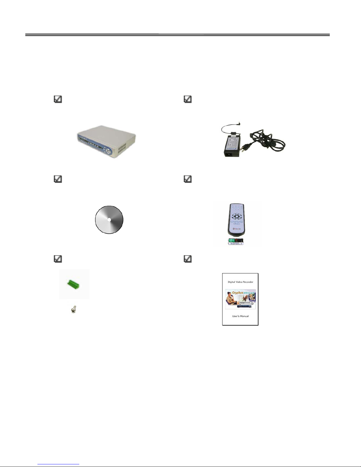
Package Contents
If any of the following items are missing, please contact your reseller.
Gryphon MPEG4 DVR G-100/4
Power Adapter
Licensed Software AP
IR remote control and
Two “AAA” size battery
Accessories Packs
User’s Manual
x 6
Page 5

4
Features and Specifications
Gryphon MPEG4 DVR series is an affordable digital video recording system supporting 4
channels, ideal for retail store, factory, small office and home with multiple location use.
With our cutting-edge industrial and the state-of-art design well compromises among
stable, robust, simple-to-use and flexibility. All for meeting your security and safety
management needs.
☆ Advanced MPEG-4 compression format
☆ Real-time viewing and Long-time recording
☆ Image quality setting: Super, High, Normal, Low and Economic
☆ Time-stamp during playback supporting
☆ Easy file portable backup methods solution
☆ 4 Sensors or DI signals trigger recording and 1 DO signal trigger supporting
☆ PTZ control through RS-485 of the system and IR remote control operating
☆ Advanced motion detection function: 5 different classes of motion detection
sensitivity, 96 grids adjustable areas of motion detection region and convenient
search function
☆ Advanced motion detection area display: Under single display mode, live and
motion detection area will be shown on selfsame division
☆ Multi-mode synchronous process: Live display, Record, Backup, Network and
Playback
☆ Powerful P/PL operation process: Live display and Playback on selfsame division
☆ 2 HDD base built-in and each can support up to 400GB
☆ Easy HDD built-in formatting
☆ Record audio with 4 CH in and 1 CH out
☆ Hardware & System WATCHDOG technology
☆ Lock/Unlock rear panel and IR remote control supporting
Page 6

5
☆ Remote surveillance system support viewer on PC through Internet or LAN
connection simultaneously
☆ Remote function supports MPEG-4 streaming for transmitting by IE over Internet
Video Compression Format Advanced MPEG 4
Video Standard NTSC / PAL (Switch)
Video Input 4 Channels, BNC composite video signal 1 Vp-p 75Ω
Video Loop Out 4 Channels, BNC composite video signal 1 Vp-p 75Ω
Video Output Monitor/TV Output: BNC composite video signal 1 Vp-p 75Ω
SPOT Monitor Output: BNC composite video signal 1 Vp-p 75Ω
S-Video Output
VGA Output (Optional)
Recording Rate D1: 720 x 480 pixels with 30 FPS (NTSC)
720 x 576 pixels with 25 FPS (PAL)
CIF: 352 x 240 pixels with 120 FPS (NTSC)
352 x 288 pixels with 100 FPS (PAL)
Recording Speed D1: 30, 25, 20, 15, 10, 5, 1, 0 FPS (NTSC)
25, 20, 15, 10, 5, 1, 0 FPS (PAL)
CIF: 120, 100, 60, 40, 20, 4, 0 FPS (NTSC)
100, 80, 60, 40, 20, 4, 0 FPS (PAL)
Real-Time Display rate 120 FPS for NTSC / 100 FPS for PAL
Image Quality Setting Super, High, Normal, Low and Economic
HDD Storage IDE type, ATA66, Support HDD x 2, Support each HDD capacity up to
400GB
Recording Mode Round-the-clock / Schedule / Motion / Sensor / Manual
Multiplex operation Live Display, Record, Playback, Backup and Network
Audio Input / Output 4 Audio Inputs, 1 Audio output (Mono)
Motion Detection Area 8 x 12 grids per camera for all channels
Motion Detect Sensitivity 5 adjustable variable with precise calculation for motion detection
Remote Transmitting Compression format MPEG-4 Streaming
Ethernet 10/100 Base-T, Support remote control and live view via Ethernet
Remote Interface Support authorized software AP, and IE browser
Network Connection Static IP address
Remote Control Remote control DVR and PTZ (RS-485) via IR transmitter
PTZ control Support famous PTZ camera protocol (PELCO D / PELCO P / DYNACOLOR
/ LILIN PIH / SCC-641 / MRX-1000 / SPD1600, 2500 / SBO-201P1 /
Page 7

6
LPT-A100L / DRX-502A) via RS-485
Camera Scan Timer Adjustable camera scan time
Sensor Input / Relay Output 4 DIs, 1DO
Key Lock / Unlock Yes
OSD Yes
Camera Title Select Yes
Video Adjustable Brightness / Contrast / Color
Date Display Format YY/MM/DD and MM/DD/YY
Power Source DC 12V
Current Consumption <42W
Operating Temperature
10°C~40°C (50°F~104°F)
Dimension (mm) 330(W) x 60(H) x 250(D) mm
☆ Design and specification are subject to change without notice.
Page 8
7
Physical Description
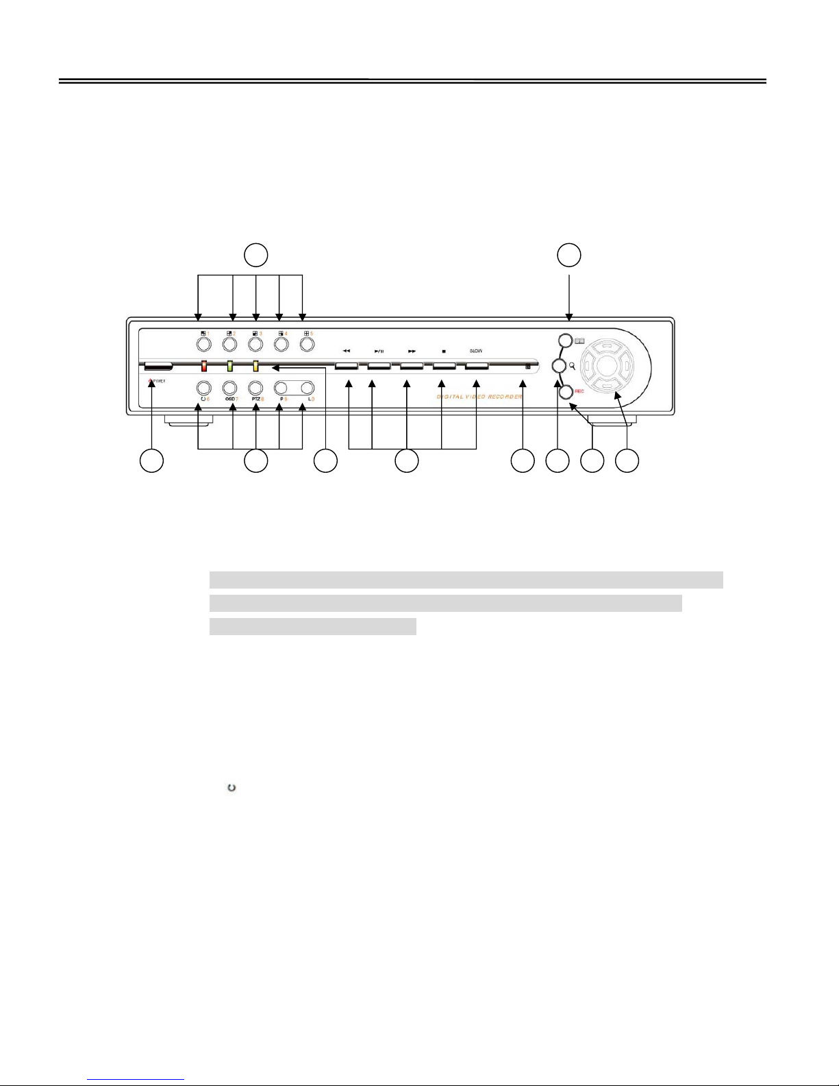
Front Panel
1. POWER (A):
Press “POWER" button to turn on / off the DVR.
Notice: Gryphon MPEG4 DVR series have a unique function to prevent insecure
issues. When turn off the DVR, user need to press POWER button
continuously over 5 seconds.
2. Camera Switch Area (B)
Press button to switch video 1 to 4 and quad display. Also compound into number
1 to 5, when entering password, date, time etc….
3. Advanced Function Select Area (C)
(1) Press “
” button to get into camera scan mode display
(2) Press “OSD” button to hide and show OSD display include camera title, DVR
system time and HDD usage percentage
(3) Press “PTZ” button to get into PTZ control mode
(4) Press “P” and “P/L” button to get into Playback display mode or Live & Playback
on selfsame display mode
Also compound into number 6 to 9 and 0, when entering password, date, time
etc….
A
B
C
D
E F
G H
I J
Page 9

8
4. Status LED’ Area (D)
(1) “POWER”: Power on
(2) “HDD”: HDD is recording or reading
(3) “LAN”: Network is accessing
5. Playback Operation Area (E)
(1) “
”: Under playback mode, press “ ” button to fast rewind
(2) “
”: Under playback mode, press “ ” button to play / pause the playback
files
(3) “
”: Under playback mode, press “ ” button to fast forward
(4) “
”: Under playback mode, press “ ” button to stop playback
(5) “SLOW”: Under playback mode, press “SLOW” button to get into slow playback
mode
6. IR Remote Control Receive Area (F)
7. Search (G):
Press “
” button to get into search mode or get back to the view mode
8. Menu (H):
Press “
” button to get into main menu, getting back to the last page or get back
to the view mode
9. Record (I):
Press “REC” button to start / stop recording manually
10. System / PTZ Operation Area (J)
(1) Under menu mode, press “ ” button to move the cursor up /
down / left / right
(2) Under configuration mode, press “
” to choose the system function or
adjustable setting value
(3) Also compound into controlling PTZ camera up / down / left / right direction
Page 10
9
under PTZ control mode
(4) Press “
” to enter the configuration, enter the subordinate configuration or
confirm setting
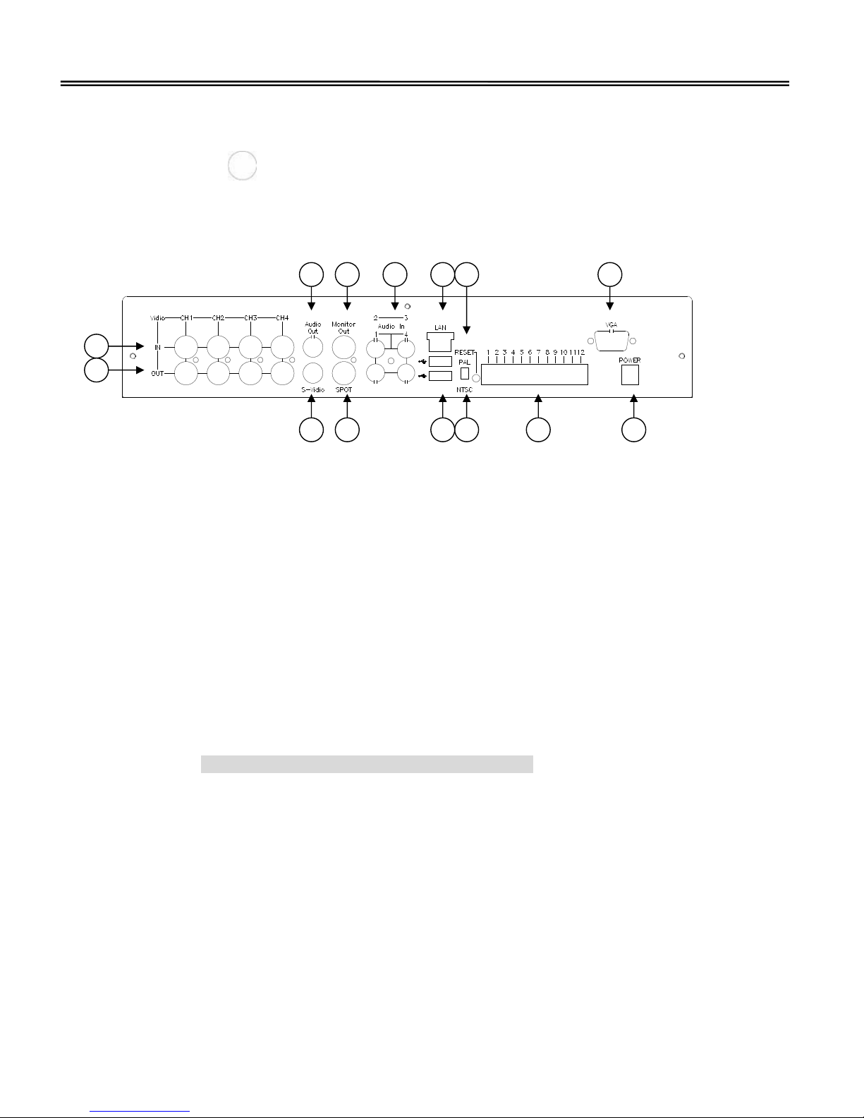
Rear Panel
1. Video inputs “IN” (A):
Connect to CHANNEL 1 to 4 video source inputs
2. Video outputs “OUT” (B):
Video outputs
3. Audio Out (C):
Connect to monitor or speaker with 1 mono audio output from the same source.
Under quad mode, user could set the default audio output source from system
configuration.
Under playback mode, audio output sounds by each channel you choose.
Note: Quad playback display mode no audio output
4. S-Video (D):
Connect to monitor with S-Video connector
5. Monitor Output (E):
Connect to main monitor
6. SPOT Monitor (F):
Connect to SPOT monitor and show the switch display. When the motion is
triggered, the SPOT monitor will show the triggered channel for a period of time
A
B
C
D
E
F
G
H I J K L M N
Page 11

10
7. Audio In (G):
Connect to audio source CHANNEL 1 to 4, such as microphone
8. LAN (H):
Connect to network by Ethernet cable
9. USB ports (I):
Support recorded files backup and firmware update
10. RESET (J):
Support the system reset function
11. PAL / NTSC switch (K):
Switch to NTSC or PAL video standard mode
12. General I/O terminal block (L)
Gryphon MPEG4 DVR series provides a very flexible general I/O interface to
combine with the user’s security devices such as sensors, alarms, lighting or door
locks. One green connector is included in the package to connect the external
devices. The general I/O terminal block has twelve pins for device control. These
pins can be divided into two categories based on their functions, including digital
inputs and outputs and RS485.
No. Pin description Regulation
1 Opto-isolated sensor input 1(+) Max. 50mA, 12V DC
2 Opto-isolated sensor input 1(-) Ground
3 Opto-isolated sensor input 2(+) Max. 50mA, 12V DC
4 Opto-isolated sensor input 2(-) Ground
5 Opto-isolated sensor input 3(+) Max. 50mA, 12V DC
6 Opto-isolated sensor input 3(-) Ground
7 Opto-isolated sensor input 4(+) Max. 50mA, 12V DC
8 Opto-isolated sensor input 4(-) Ground
9
Relay output 1 Max. 2A, 24V DC or 2A, 120V AC
10 Common Short with NC at initial state
11 RS485 A D+, non-inverting
12 RS485 B D-, inverting
Page 12

11
Digital I/O control
Gryphon MPEG4 DVR series provides four pairs of digital inputs and one set of relay
switch. Pin 1 to pin 10 can be connected to external sensors and the state of voltage
will be monitored according to the programmed conditions on the configuration
page. Relay switch can be used to turn on or off external devices. When the system
starts up, COMMON of relay switch will be short with NC.
RS485 interface
If the device connected to RS485 interface, wire two control lines to pin 11 and pin
12. After switching to PTZ on the configuration page, the PTZ control commands will
be directed through pin 11 and pin 12. If the distance from the controlled device is
too far to allow accurate function, an external power source may be used to amplify
the RS485 signal.
13. VGA port (M):
Connect to VGA connector card
Notice: Gryphon MPEG4 DVR series support Monitor / SPOT monitor / S-Video /
VGA (optional) Outputs at the same time, no need to switch.
14. POWER (N):
Connect to provided Adapter
The power adapter of Gryphon MPEG4 DVR series and the external power supply
are prohibited to exist together. Only one source can feed power to Gryphon MPEG4
DVR series. Improper usage will result in serious damage.
Page 13

12
How to Install
To easily fit into various environments, Gryphon MPEG4 DVR series
automatically detects the attached interfaces and configures itself to the best
condition. Therefore users need not care whether the connected cameras are
either NTSC or PAL (But we recommended that all cameras’ video standard
should be suitable for the same display video standard mode to get the best
quality), and whether the Ethernet speed is 10Mbps or 100 Mbps.
Gryphon MPEG4 DVR series supports Ethernet interfaces according to the user's
existing network. Ethernet can provide higher bandwidth to achieve the best
performance in current Internet applications. Refer to the related installation
section for your network environment.
In the following content, "user" refers to those who can access Gryphon MPEG4
DVR series and "administrator" means the supervisor who has the power to set
password and configure Gryphon MPEG4 DVR series in addition to general
access. Administrators should carefully read this manual, especially during
installation.
Page 14
13
Physical Connection
Hardware installation
1. Install HDDs
The HDDs must be installed before the Gryphon MPEG4 DVR is turned on. Carefully
following the steps to ensure correct installation:
Notice: If you want to install two HDDs, please set one HDD to “Master Mode” or
“Single Mode”, and the second one to “Slave Mode”
(1) Open the upper cover of the Gryphon MPEG4 DVR
(2) Screw HDD to the HDD bracket
(3) Connect the HDD to power connector and IDE BUS (make sure to align the HDD
precisely to the pin connection)
(4) Secure the HDD bracket to the Gryphon MPEG4 DVR
(5) Close the upper cover of the Gryphon MPEG4 DVR
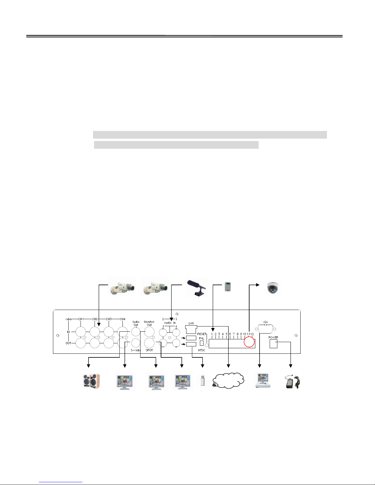
2. The illustration below will show you how to connect cameras and monitor to
Gryphon MPEG4 DVR
3. Connecting or replacing the Gryphon MPEG4 DVR series to your existing CCTV
Surveillance System as shown below
…
Camera 1 Camera 4
Audio In
Control for PTZ camera Alarm Sensors
Speaker
Main Monitor
(S-Video Connector)
Main Monitor
SPOT Monitor
Internet
USB disk
VGA Monitor
Adapter
Page 15
14
Getting Started
1. Before using the Gryphon MPEG4 DVR series, please ensure the HDDs installed
ready
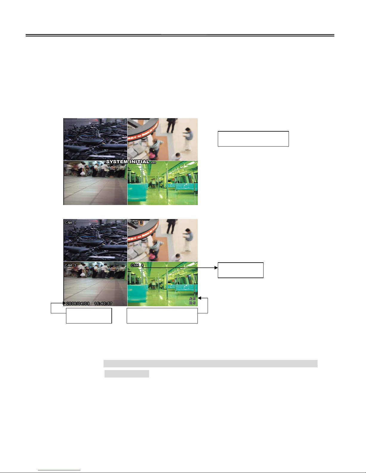
2. Connect the AC power cord to Power Adapter and plug into an electrical outlet. The
POWER LED will be green. It need approximately 25 to 30 seconds to check and
boot the system with the message: “SYSTEM INITIAL …”
3. First access to Gryphon MPEG4 DVR series, please:
(1) Change initial password (default password is “0000”) under system
configuration page, and remember your new password.
Notice: Under enter the menu, Lock mode and IE browser, you should login
with password
(2) Format the HDDs under system configuration page.
(3) Set up the system time (for setting system time, please refer to “DATE / TIME”
settings)
(4) Complete the network settings (If you need to use remote application “Multi
Viewer” or IE browser for further remote management operating)
SYSTEM INITIAL…
System Time
Usage Capacity of HDDs
Channel Title
Page 16
15
Basic Operations
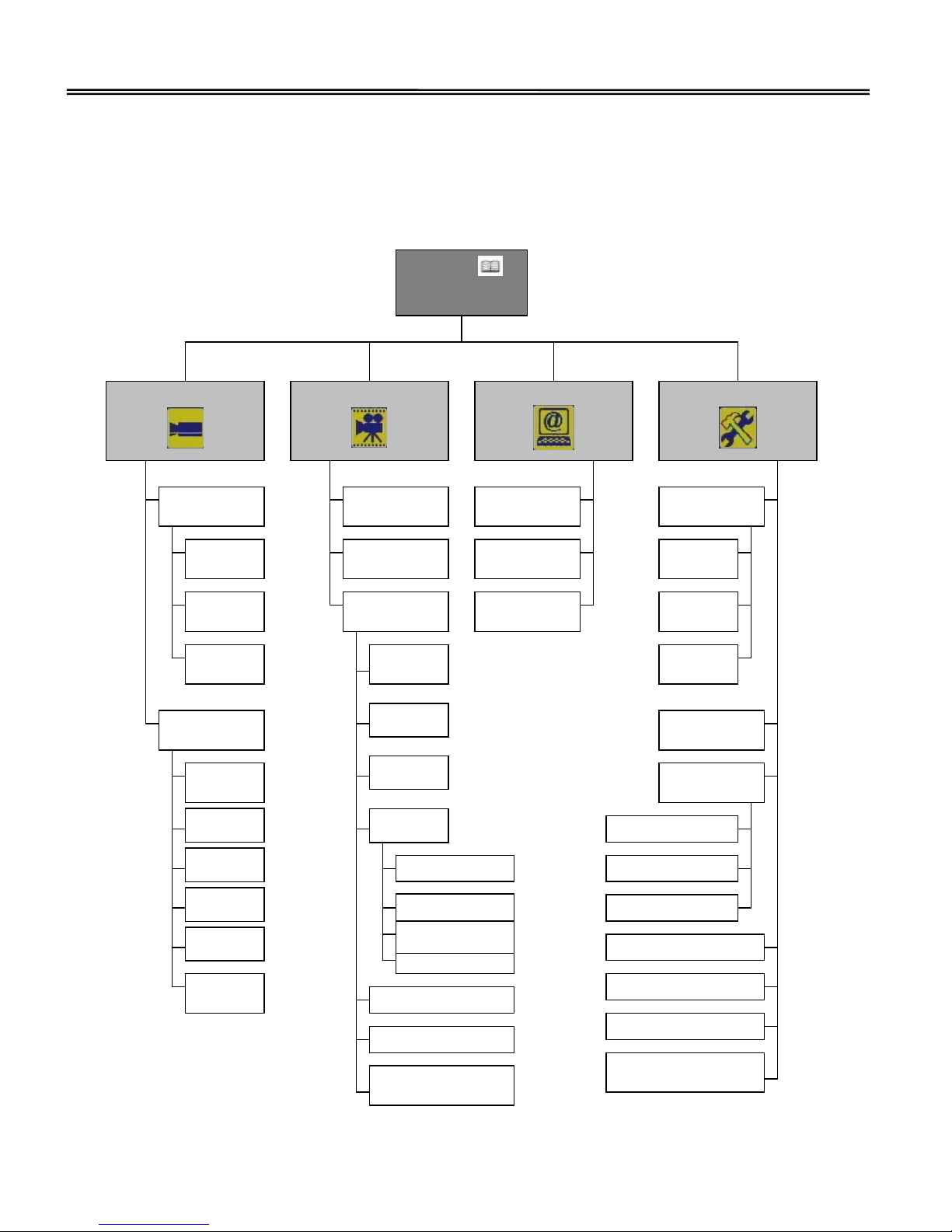
Menu Diagram
MENU ( )
SETUP
CAMERA SETTING
RECORD SETTING
NETWORK SETTING
SYSTEM SETTING
PTZ CAMERA
SETUP
CAMERA
SETUP
CHANNEL
ENABLE
PTZ
MODE
L
SPEED
VALUE
TITLE
SELECT
BRIGHTNESS
VALUE
CONTRAST
VALUE
COLOR
VALUE
MOTION AREA
SETUP
MOTION
SENSITIVITY
VALUE
RESOLUTION
SELECT
OVERWRITE
SELECT
CAMERA
SETUP
ROUND-THE
-CLOCK
SELECT
MOTION
SELECT
SENSOR
SELECT
SCHEDULE
SETUP
SCHEDULE SELECT
ALL CAMERAS APPLY
DAILY SCHEDULE
SETTING
QUALITY SELECT
FRAME RATE VALUE
VIDEO LOSS DETEC
T
SELECT
IP ADDRESS
VALUE
MASK
VALUE
GATEWAY
VALUE
DATE/TIME
SETUP
FORMAT
SELECT
DATE
VALUE
TIME
VALUE
HDD INFO
FORMAT
EXT. ALARM
SETUP
ALARM SELECT
T
YPE SELECT
DELAY TIME VALUE
PASSWORD SETUP
LOCK KEYPAD SELECT
CAMERA SCAN VALUE
QUAD AUDIO OUT
SELECT
Page 17
16
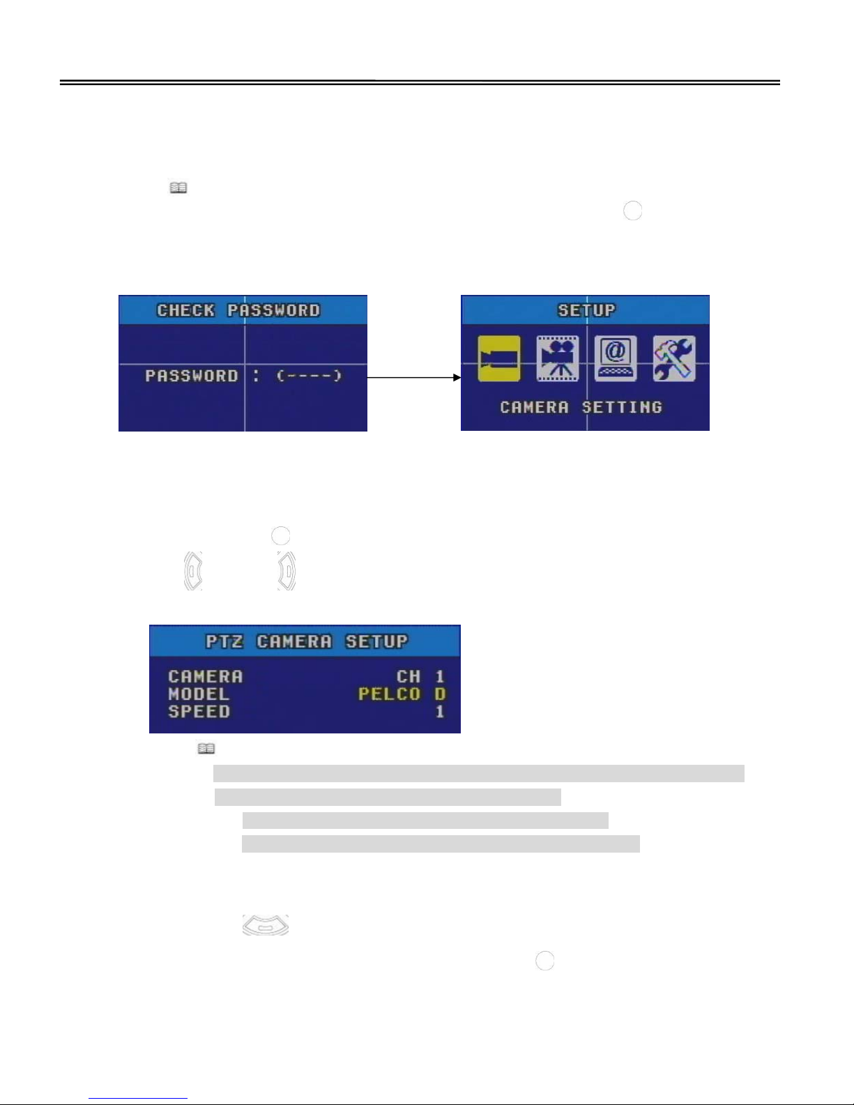
CAMERA SETTING
Press “ ” button and insert the password (default password is 0000) to get into SETUP
page and move cursor to CAMERA SETTING, and then press the enter (
) button to get
into CAMERA SETUP page.
1. PTZ CAMERA SETUP
Press the enter (
) button to get into PTZ CAMERA SETUP page and you can use
left (
) or right ( ) button to choose which CAMERA you want to connect, which
PTZ camera’s MODEL you use, and adjust PTZ camera’s speed value from 1 to 10.
Press
button to get back to CAMERA SETUP page when finished setting.
Notice: Gryphon MPEG4 series type of 4CH DVR only support one pair of RS-485
(D+, D-) to connect PTZ camera and you need:
(1) Fixed only one channel for connecting PTZ camera
(2) PTZ camera’s ID / Address also need to be fixed at “1”
2. CAMERA SETUP
Press down (
) button to each CAMERA SETUP and move the cursor to which
camera you need to setup and then press the enter (
) button to get into:
Page 18
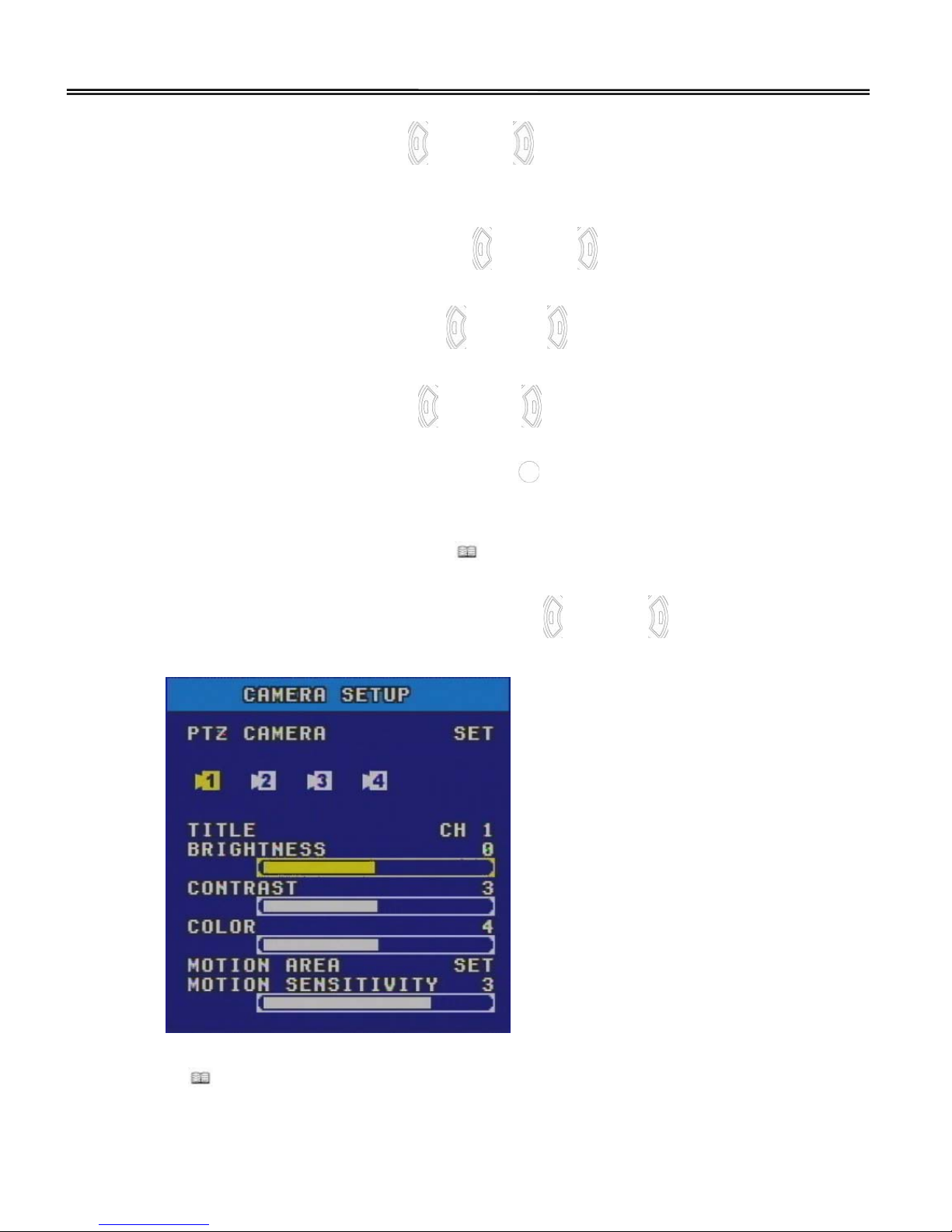
17
(1) TITLE SELECT, press left ( ) or right ( ) button to select three types of
camera title display: “1, 2, 3, 4”, “CH1, CH2, CH3, CH4” or “CAM1, CAM2,
CAM3, CAM4”.
(2) BRIGHTNESS ADJUST, press left (
) or right ( ) button to adjust image
brightness value from -128 to 127.
(3) CONTRAST ADJUST, press left (
) or right ( ) button to adjust image contrast
value from -128 to 127.
(4) COLOR ADJUST, press left (
) or right ( ) button to adjust image color value
from -128 to 127.
(5) MOTION AREA CLEAR, Press the enter (
) button to get into MOTION AREA
page and move the cursor to the block, and then press enter button to clear the
detecting area away you need (Clear the mask away means that area no need
to detect motion status). Press “
” button to get back to CAMERA SETUP page
when finished setting.
(6) MOTION SENSITIVITY ADJUST, press left (
) or right ( ) button to adjust
motion detecting sensitivity value from 1 to 5.
Press “
” button twice to get back to SETUP page, when you finished all CAMERA
SETTING configuration.
Page 19

18
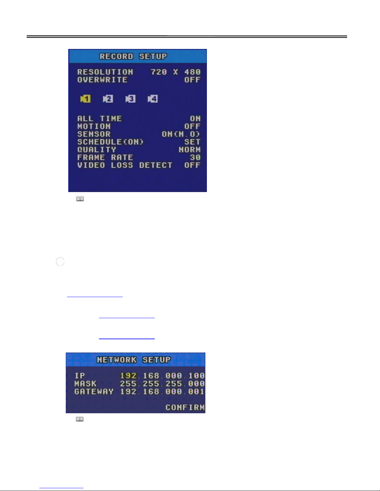
RECORD SETTING
Under SETUP page, move the cursor to RECORD SETTING, and then press the enter ( )
button to get into RECORD SETTING page.
1. RESOLUTION SELECT
Gryphon MPEG4 series type of 4CH DVR support two models of resolution to select:
NTSC: CIF 352 x 240 or D1 720 x 480, PAL: CIF 352 x 288 or D1 720 x 576, and
press left (
) or right ( ) button to select recording resolution model.
2. OVERWRITE SELECT, ON or OFF the HDDs overwrite function and if you ON the
overwrite function; DVR will overwrite the oldest recorded video file to replace the
newest one when HDDs are full.
Notice: (1) If administrator setup overwrite function is “ON”, DVR will reserved 5%
of HDDs capacity for better performance use automatically and maybe
overwrite without further warning notices.
(2)If OFF the overwrite function, when the HDDs are full that DVR will back
to un-recording view mode and maybe without further notices.
3. CAMERA RECORD SETUP
Press down (
) button to each CAMERA RECORD SETUP and move the cursor
to which camera you need to setup and then press the enter (
) button to get into:
(1) ROUND-THE-CLOCK SELECT, ON or OFF the round-the-clock recording mode
setting
(2) MOTION SELECT, ON or OFF the motion recording mode setting
(3) SENSOR SELECT, ON or OFF the sensor-in recording mode setting
(4) SCHEDULE SETUP, press the enter (
) button to get into SCHEDULE SETUP
page and administrator can
A. ON or OFF SCHEDULE function
B. APPLY “ALL CAMERAS” under the same weekly schedule setting or not
C. Move the cursor to what day you need to setup recording schedule and press
the enter (
) button to get in, and then move the cursor to the hour, press
Page 20
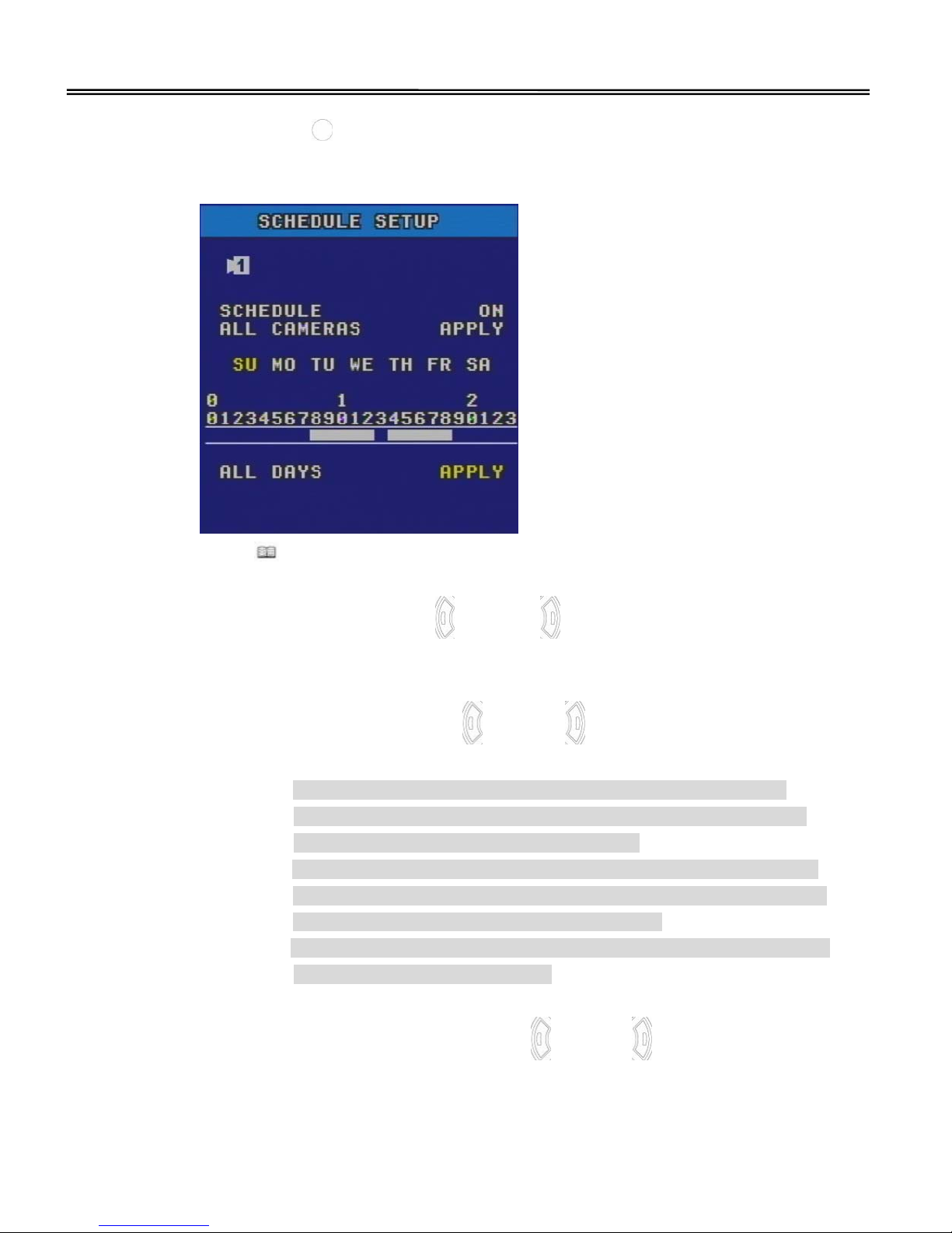
19
the enter ( ) button to setup your daily record schedule (clear the white
bar away means that time period no need to record on schedule).
D. APPLY “ALL DAYS” under the same daily schedule setting or not
Press “
” button twice to get back to RECORD SETUP page, when you finished
all SCHEDULE SETTING configuration.
(5) QUALITY SELECT, press left (
) or right ( ) button to select five models of
image recording quality: SUP (Super), HIGH, NORM (Normal), LOW or ECON
(Economic)
(6) FRAME RATE SELECT, press left (
) or right ( ) button to select each camera
need to record how many frames (0, 1, 5, 10, 15, 20, 25, 30) per second.
Notice: A. Under NTSC: D1 720 x 480 or PAL: D1 720 x 576 resolution
recording model, Gryphon MPEG4 series type of 4CH DVR only
support 30 or 25 frames for four channels.
B. If total exceed recording frames limitation, DVR will show notice
message “TOTAL FPS EXCEED 30!” under NTSC model or “TOTAL
FPS EXCEED 25!” under PAL mode on screen.
C. Under CIF size resolution recording model, each channel can select
the maximum FPS for recording
(7) VIDEO LOSS DETECT SELECT, press left (
) or right ( ) button to select each
camera need to show “VIDEO LOSS” on screen or not, if video loss is coming
up.
Page 21
20
Press “
” button twice to get back to SETUP page, when you finished all RECORD
SETTING configuration.
NETWORK SETTING
Under SETUP page, move the cursor to NETWORK SETTING, and then press the enter
(
) button to get into NETWORK SETTING page.
1. IP ADDRESS SETUP, press number button to insert static IP address. For example,
192.168.000.100
2. MASK ADDRESS SETUP, press number button to insert subnet mask address. For
example, 255.255.255.000
3. GATEWAT ADDRESS SETUP, press number button to insert gateway address. For
example, 192.168.000.001
Press “
” button one time to get back to SETUP page, when you finished all NETWORK
SETTING configuration.
Page 22
21
SYSTEM SETTING
Under SETUP page, move the cursor to SYSTEM SETTING, and then press the enter ( )
button to get into SYSTEM SETTING page.
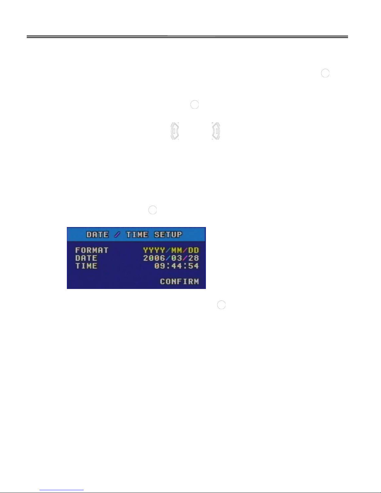
1. DATE / TIME SETUP, press the enter (
) button to get into DATE / TIME SETUP
page and you can
(1) FORMAT SELECT, press left (
) or right ( ) button to select two types of date
/ time format: YYYY/MM/DD or MM/DD/YYYY
(2) DATE VALUE, move the cursor to DATE and press number button to insert the
date you need
(3) TIME VALUE, move the cursor to TIME and press number button to insert the
time you need
(4) When finished the DATE / TIME SETUP, please move the cursor to “CONFIRM”
and press the enter (
) button to confirm the setting
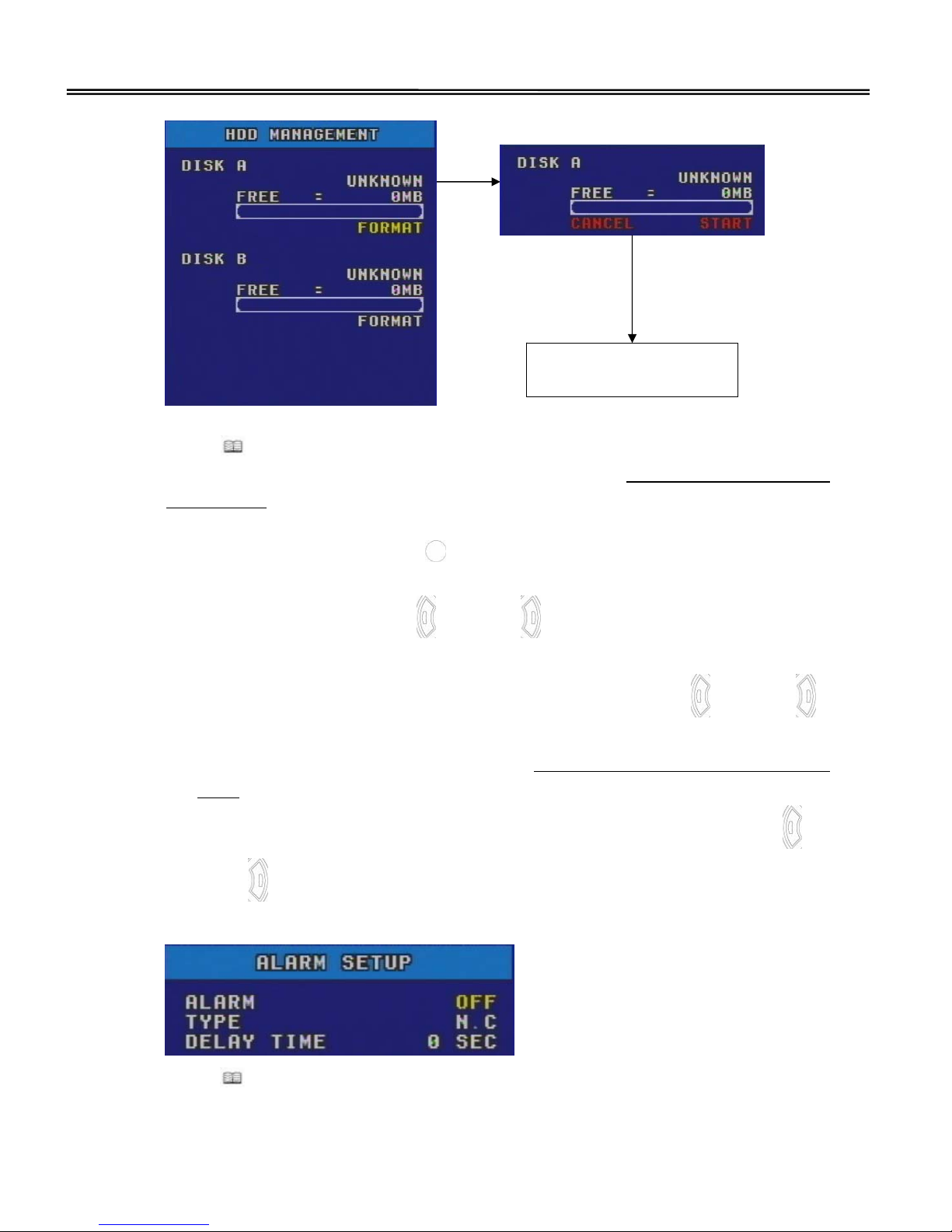
2. HDD INFO / FORMAT SETUP, press the enter (
) button to get into HDD
MANAGEMENT page and you can press the enter button to execute “FORMAT” the
HDD function. When administrator make sure to “START” format the HDD, DVR will
show “PROCESSING” till the HDD format complete and show the HDD capacity
automatically such as:
Page 23
22
Press “
” button one time to get back to SYSTEM SETUP page, when you finished
all HDDs format processing. (Please refer to the chapter Hardware installation, 1.
Install HDDs for more information)
3. ALARM SETUP, press the enter (
) button to get into ALARM SETUP page and you
can
(1) ALARM SELECT, press left (
) or right ( ) button to select ON or OFF ALARM
output (relay 1) function
(2) TYPE SELECT, move the down cursor to TYPE and press left (
) or right ( )
button to select two models of relay output: N.C (Normal Close) or N.O (Normal
Open) status (Please refer to the chapter Rear Panel, 12. General I/O terminal
block for more information)
(3) DELAY TIME VALUE, move the down cursor to DELAY TIME and press left (
) or
right (
) button to select the value from 0 to 60 seconds alarm output delay
time period
Press “
” button one time to get back to SYSTEM SETUP page, when you finished
all ALARM SETUP configuration
TOTAL = 112673MB
FREE = 106917MB
Page 24
23
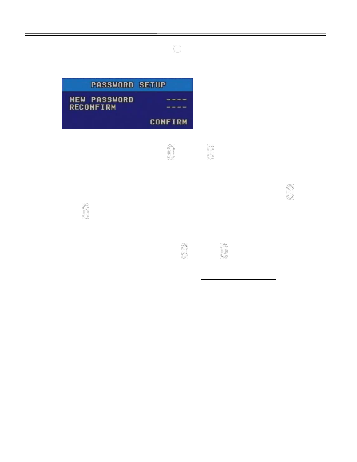
4. PASSWORD SETUP, press the enter ( ) button to get into ALARM SETUP page and
you can setup NEW PASSWORD, RECONFIRM password and CONFIRM for getting
back to SYSTEM SETUP page
5. LOCK KEYPAD SELECT, press left (
) or right ( ) button to select ON or OFF the
keypad lock. If you setup ON the KEYPAD LOCK mode, press any button and then
key in the password to enter the system
6. CAMERA SCAN VALUE, move the cursor to CAMERA SCAN and press left (
) or
right (
) button to select the value from 0 to 60 seconds camera scan delay time
period
7. QUAD AUDIO OUT SELECT, press left (
) or right ( ) button to select which
channel (CH1, CH2, CH3 or CH4) you need to broadcast audio output display under
quad view mode (please refer to the chapter Rear Panel, 3. Audio Out
for more
information)
Page 25

24
Press “
” button one time to get back to SETUP page, when you finished all SYSTEM
SETTING configuration.
Page 26

25
Advanced Functions
Motion Detection
Gryphon MPEG4 DVR series support advanced motion detection setting, giving you a
better user friendly environment.
Press “
” button and insert password to enter SETUP page, choose CAMERA SETTING
and press “
” button to get in. Move cursor to channel you need set motion detection
and press “
” button to get in. Move cursor to MOTION AREA and press “ ” to get
in MOTION AREA setting.
Press “
” button to move the cursor and press “ ” button to clear the
unnecessary motion detection area away.
Notice: Gryphon MPEG4 DVR series have unique advanced motion detection design
about:
1. Based on MOTION AREA setting could be workable, and under RECORD
SETTING, please move the cursor and press “ ” or “ ” to “ON” the
MOTION recording function first. When “ON” the MOTION recording
function, DVR will be detecting full image area that is under motion
detection.
2. In this function, our default setting is detecting any area. Light blue
represent the area that is being detected. While the transparent blocks is
the area that is under un-detecting area.
Page 27

26
Quick Search
Gryphon MPEG4 DVR series support advanced quick event search function, give you a
better user friendly environment.
Press “
” button to enter to PLAYBACK RECORD SEARCH and press “ ” or “ ” button
to move the SEARCH CRITERIA MODE to “ALL MODES”, “ROUND-THE-CLOCK (R)”,
“MOTION (M)” and “SENSOR (S)”. Then, move the cursor to “START” / “END” and insert
the date / time that you need to search.
Move the cursor to “SEARCH” and press “
” button to get into “PLAYBACK RECORD
LIST”, and move the cursor to the event you need, and then playback.
Move the cursor and
press “ ” to clear
the detecting area
away
Search mode adjustable:
ALL MODES,
ROUND-THE-CLOCK (R)
,
MOTION (M),
SENSOR (S)
Move the cursor and
insert the number
Page 28

27
Playback
When complete searching PLAYBACK RECORD LIST, press “ ” button, the DVR will
display the recorded file video you have selected. Gryphon MPEG4 DVR series offers two
playback modes: Playback
(press “P” button) and Live show & playback (press “P/L”
button). Press “
” button once, play will be paused.
1. Fast Forward (F.F.) & Fast Rewind (REW):
You can increase speed for Fast Forward and Rewind on the DVR. In the Playback
(“P” or “P/L”) mode,
(1) Press “
” button once to get 2X speed and press twice to get 4X … and the
maximum speed can up to 32X.
(2) Press “
” button once to get 2X speed and press twice to get 4X … and the
maximum speed can up to 32X.
(3) During playback (“P” or “P/L”) mode, the shown on the screen is playback time
(PB: XXXX/XX/XX XX:XX:XX) and the type of recording image size (PB: CIF /
D1).
2. STOP:
Press “
” button under all circumstance, it will return to PLAYBACK RECORD LIST
for choosing the other recorded file video to play or press “
” button twice to get
back to live show mode.
Page 29

28
3. Channel Shift:
(1) On Playback
mode, press “P” button to select display mode (Channel 1 to 4 full
screens and Quad display)
(2) On Live show & playback
mode, press “P/L” button to select display mode
(Channel 1 to 4 and Quad display shown on channel 4)
4. Slow Playback:
Press “SLOW” button to get 1/2X speed playback and press twice to get 1/4X speed,
three times to get 1/8X speed, four times to get 1/16X speed and five times to get
1/32 speed.
Recording
Gryphon MPEG4 DVR series offers five recording modes: Round-The-Clock recording,
Manual record, motion recording, sensor-in recording and scheduled recording. If
power is off accidentally, recorded files will still be stored in the HDDs.
1. Manual Record: Recording or not is initiated by manual pressing the “REC” button.
Indicated by the sign “ ”
2. Scheduled Recording: Recording is scheduled by “SCHEDULE SETUP” list. Indicated
by the sign “
”
3. Round-the-clock Recording: The DVR default record setting is round-the-clock
“ON” (and others off).
In first time to use the DVR, press “REC” button for recording and round-the-clock
recording mode will become effective from now on.
4. Motion Recording: When motion detection function is activated, the recording is
triggered by motion alarm. Indicated by the sign “ M ”
5. Sensor Recording: When sensor input is activated, the recording is triggered by
sensor alarm. Indicated by the sign “ S ”
Notice: 1. If you need to change any recording parameter, system will become
effective automatically when next REC start-up.
2. Under “Scheduled recording” mode, manual record is not workable
simultaneously during schedule recording. Unless you get into RECORD
SETUP page and OFF SCHEDULE in proceed.
Page 30

29
Additional Operations
USB Backup / Network Upgrade
Gryphon MPEG4 DVR series support users can use USB drive for backup, and Network
for upgrade.
1. USB Backup:
(1) Please format the USB disk to “FAT32” first
(2) Go to the SYSTEM SETTING page and move the cursor to USB BACKUP, and
press enter button
(3) Select the recorded time criteria and press “START” to confirm USB BACKUP
2. Network Upgrade: (Please see the README.TXT from CD for more directions)
(1) Download the upgrade file “GRYPHONE.BIN” from the web
(2) Save the upgrade file “GRYPHONE.BIN” in your PC
(3) Click the “TFTPServer” program from our attached licensed CD Utility folder
(4) Browser the file “GRYPHONE.BIN” from your PC
(5) Click “START SERVER” to confirm upgrade
(6) Please read the “README.TXT” from our attached licensed CD for more
information
Licensed software “Multi Viewer”
Gryphon MPEG4 DVR series support users can use AP “MultiViewer” for remote
accessing the DVR.
1. Install Software:
(1) Put the attached licensed CD into a CD-ROM and click the “MultiViewer.exe” to
install application program into your PC
Page 31

30
(2)Click “Next”
(3) Insert your User Name and Company Name and click “Next”
Page 32

31
(4)Choose destination location and click “Next”
(5) Select Program folder location and click “Next”
(6) Click “Finish” to complete the setup and you will see the path on the program
Page 33

32
2. Software Operation
(1) Click
to enter “MultiViewer” application
(2) Click the “
” button and Key in static IP address. Select the channel and
optional function you need to use, and then click “OK” to exit “Server Config”
page.
Notice: Before using remote access software “MultiViewer”, please make sure:
1. The administrator open the network service port from 40001 to 40017,
DVR system set the correct IP address, and already link to network.
2. DVR system did under recording status.
3. You had upgrade to “DirectX 9” on your PC or please refer to CD for
installing DirectX 9.
Time Display
Area
System
Operate Area
Playback
Operate Area
Camera Select
Show Division
Select
Page 34

33
(3) Click the “ ” button to connect to the DVR system as below. You can select the
show division and channel to operate remote monitoring.
(4) Click the “
” button to snapshot the monitor picture you need, and browser the
file folder and file type you need to save.
(5) Click the “
” button to remote download the recording file you need, and
user should enter the start / end time to search the recording history criteria.
Browser the history file path you need to save, select the Whole or Range
download mode and then start to download. When remote download finished,
the system notice message will show on “Connecting Status” column.
Page 35

34
(6) Click the “
” button to execute the playback function and browser the
recording file you download, and then open the file.
Notice: Before you use playback function, you need to disconnect the remote
viewing mode first.
(7) Use the “Playback Operate Area” function keys to execute the “
play”, “
pause”, “
stop”, “ step forward”, “ step rewind”, “ fast forward” or
“
fast rewind” function to operate playback.
System Time
Playback Time
Page 36

35
Remote Accessing by IE
Gryphon MPEG4 DVR series support users can use IE browser to remote accessing the
DVR.
1. Open the IE browser and key in the DVR IP address.
2. Key in the user account, password and login. (If the administrator didn’t change the
DVR password, the default is root / 0000 )
3. When you first time to view the video by IE, please click “R4Web
” link and execute
the ActiveX setup file upper the window.
Notice: Before you use IE explore to view live video, please make sure that DVR did
under recording status.
Show Division
Select
Channel Select
2X Image Amp.
Connect /
Disconnect
Page 37

36
Trouble Shooting
Please refer to the FAQ table below for easy trouble shooting. The table below describes
some typical problems and also their solutions. Please check them before calling your
DVR dealer.
PROBLEM SOLUTION
Check power cord connection No power
Confirm that there is power at the outlet
Check if it is under LOCK KEYPAD mode
No working when pressing any button
Press any button and then key in the password to
exit LOCK
KEYPAD mode
No recorded video
Check if the HDD is installed, Formatted and
connected properly
Recording status didn’t work
Confirm that you had re-start REC after changing
any recording parameter.
Schedule record does not working Check if the SCHEDULE is set to (ON)
Check camera video cable and connection
Check monitor video cable and connection
Confirm that the camera is power supplied
No live video
Check the setting of camera lens
Switch NTSC / PAL mode
Please stop record and reset the DVR after you
switch the NTSC / PAL video type of the DVR
Confirm that you had transferred the *.dss to *.avi
file type by DSSConvert.exe from licensed CD
“Windows Media Player”, “WINDVD” and “Power
The media player of the recorded files
If you can not view the *.avi file, please refer to CD
and execute “ffdshow.exe” to upgrade the codec
program
MultiViewer: Please refer to CD and setup “DirectX 9” first
IE explore:
1. After log in, please click the “R4Web” link to
execute the ActiveX setup file
2. Confirm that your “Internet Options”Æ“Internet”
& “Trusted sites” configurations, no any ActiveX
setup been set to Disable
No live video from remote site
Network Service: Confirm that network service
ports 80 and from 40001 to 40017 had already been
opened by administrator
Show “Connecting” and no live video
from remote site
Confirm that the DVR system did under recording
status
(Notice: All other trademarks or registered marks in this manual belong to their respective manufacturers.)
Page 38

37
Appendix
Remote IR Transmitter
Gryphon MPEG4 DVR series support users can use IR remote control transmitter to
operate the DVR system.
(1) Power
(2) Number Selection buttons
(3) Camera Switch
(4) Camera Scan
(5) OSD
(6) PTZ
(7) Playback
(8) Live & Playback
(9) Menu
(10) Left, Down, Up, Right
(12) Zoom+
(13) Zoom-
(14) Focus+
(15) Focus-
(17) REC (16) AUTO
(18) Search (19) Fast forward
(20) Fast rewind
(21) Playback & Pause
(22) Stop (23) Slow playback
(11) SET
Page 39

38
(1) Power:
Press this button to power on / off the DVR.
(2) Number Selection buttons:
Press the
buttons to select numbers.
(3) Camera Switch:
Press 1 to 5 to select channel and quad mode.
(4) Camera Scan:
Press this button to get into camera scan mode display.
(5) OSD:
Press this button to hide / show OSD display, include camera title, DVR system
time and HDD usage percentage.
(6) PTZ:
Press this button to get into PTZ control mode.
(7) Playback:
Press this button to get into Playback display mode.
(8) Live & Playback:
Press this button to get into Live & Playback display mode.
(9) Menu:
Press “
” button to get into main menu, its subsidiary, or back to the last page.
(10) Left, Down, Up, Right
(A) Under menu mode, press these buttons to move the cursor up / down / left /
right
(B) Under configuration mode, press these buttons to choose the system function
or adjustable setting value
(C) Also compound into controlling PTZ camera up / down / left / right direction
under PTZ control mode
Page 40

39
(11) SET:
Press the “SET” button, to enter a submenu / to confirm the selection.
(12) Zoom+:
Press this button to change the optical zoom in ratio of the PTZ.
(13) Zoom-:
Press this button to change the optical zoom out ratio of the PTZ.
(14) Focus+:
Press this button to change the optical focus in ration of the PTZ.
(15) Focus-:
Press this button to change the optical focus out ratio of the PTZ.
(16) AUTO:
Press this button to start the PTZ auto-navigation function.
(17) REC:
Press this button to start the recording function of 1 to 4 channels.
(18) Search:
Press “
” button to get into search mode or get back to the view mode.
(19) Fast forward:
Under playback mode, press “
” button to fast forward.
(20) Fast rewind:
Under playback mode, press “
” button to fast rewind.
(21) Playback & Pause:
Under playback mode, press “ ” button to play / pause the playback files.
(22) Stop:
Press this button to stop the playback.
(23) Slow playback:
Under playback mode, press “SLOW” button to get into slow playback mode.
Page 41

40
Recording Hours on 120GB HDD
Recording Results in NTSC Format
Video Signal Resolution Video Quality
30 fps 15 fps 7 fps 1 fps
Super
146 Hours 292 Hours 657 Hours 4,380 Hours
High
207 Hours 415 Hours 918 Hours 6,198 Hours
Normal
268 Hours 536 Hours 1,206 Hours 8,084 Hours
Low
332 Hours 665 Hours 1,495 Hours 9,960 Hours
NTSC
D1
(720x480)
Economic
372 Hours 745 Hours 1,674 Hours 11,160 Hours
Recording Results in NTSC Format
Video Signal Resolution Video Quality
120 fps 60 fps 30 fps 4 fps
Super
62 Hours 124 Hours 297 Hours 1,856 Hours
High
119 Hours 237 Hours 568 Hours 3,550 Hours
Normal
222 Hours 444 Hours 1,065 Hours 6,656 Hours
Low
230 Hours 460 Hours 1,104 Hours 6,900 Hours
NTSC
CIF
(320x240)
Economic
320 Hours 656 Hours 1,574 Hours 9,837 Hours
Recording Results in PAL Format
Video Signal Resolution Video Quality
25 fps 12 fps 6 fps 1 fps
Super
164 Hours 341 Hours 682 Hours 4,092 Hours
High
246 Hours 512 Hours 1,024 Hours 6,144 Hours
Normal
287 Hours 597 Hours 1,194 Hours 7,164 Hours
Low
334 Hours 695 Hours 1,390 Hours 8,340 Hours
PAL
D1
(720x576)
Economic
359 Hours 747 Hours 1,494 Hours 8,964 Hours
Recording Results in PAL Format
Video Signal Resolution Video Quality
100 fps 50 fps 25 fps 4 fps
Super
79 Hours 158 Hours 316 Hours 1,975 Hours
High
146 Hours 292 Hours 584 Hours 3,650 Hours
Normal
233 Hours 466 Hours 932 Hours 5,825 Hours
Low
266 Hours 532 Hours 1,064 Hours 6,650 Hours
PAL
CIF
(352x288)
Economic
345 Hours 690 Hours 1,380 Hours 8,625 Hours
(Notice: This recording sheet only for your reference, cause the statistics will be changeable by live image variation.)
Page 42

1
目 錄
貨品內容 ................................................................................1
特性說明 ................................................................................2
產品規格 ................................................................................3
主機操作說明...........................................................................4
前面板操作說明 ........................................................................................4
背板操作說明 ...........................................................................................6
硬體暨接線說明........................................................................9
硬體安裝.................................................................................................9
操作起始...............................................................................................10
基本操作說明.........................................................................11
攝影機設定............................................................................................11
錄影設定...............................................................................................13
網路設定...............................................................................................15
系統設定...............................................................................................16
進階功能說明.........................................................................19
動態偵測...............................................................................................19
快速搜尋...............................................................................................20
錄影回放...............................................................................................21
錄影說明...............................................................................................22
其他操作說明.........................................................................23
USB備份 / 遠端更新軟體.........................................................................23
遠端監控軟體 “MultiViewer” ..................................................................23
IE網路瀏覽器.........................................................................................30
排障說明 .............................................................................. 31
附錄....................................................................................32
遙控器操作說明 ......................................................................................32
錄影容量比較表(以 120GB硬碟為例)...........................................................35
Page 43

1
貨品內容
請詳細檢查您所收到的貨品內容物,如有遺漏請緊急聯絡您的設備供應商予以補足。
Gryphon MPEG4
數位錄影主機
G-100/4
電源組
產品出貨AP光碟
紅外線遙控器及標準四號電池2個
零配件組
專用簡易操作手冊
x 6
Page 44

2
特性說明
Gryphon MPEG4 DVR 數位監控主機系統提供四路錄影功能, 可適用於超商連鎖
店、廠房、中小型企業、辦公室以及家庭等各式不同環境使用。搭配工業等級及商品視
覺化的設計,提供使用者穩定效能、堅固耐用及操作簡便等彈性化的運用,完全為您最
高等級的安全防護需求量身訂製。
☆ Advanced MPEG-4 硬壓格式
☆ 即時同步監看及超長時間錄影功能
☆ 錄影品質設定: 最高、高、一般、低、最低
☆ 支援錄影回放時間顯示功能
☆ 支援可攜式錄影資料備份功能
☆ 支援4組DI觸發錄影及1組DO發報功能
☆ 支援1組RS-485連接控制PTZ攝影機,及紅外線遙控器操作功能
☆ 動態檢知功能: 5種靈敏度等級設定,96格可調式動態檢知區域設定,以及快速搜
尋動態歷史事件等功能
☆ 進階瀏覽P/PL功能: 可單獨進行錄影回放,或監看與錄影回放同時瀏覽
☆ 同步多工模式: 即時監看、錄影、備份、網路及錄影回放
☆ 可內置2顆硬碟,單一硬碟容量最大可支援400GB
☆ 簡易快速硬碟格式化功能
☆ 支援4路錄音及1路監聽現場音、錄音回放功能
☆ 支援硬體及系統WATCHDOG功能
☆ 支援前面板及紅外線遙控器密碼鎖定/取消鎖定功能
☆ 提供遠端同步監看及錄影資料回放應用程式
☆ 提供MPEG4網路傳輸,遠端同步IE瀏覽監看功能
Page 45

3
產品規格
視訊壓縮格式
Advanced MPEG 4
視訊標準
NTSC / PAL (Switch)
視訊輸入
4 Channels, BNC composite video signal 1 Vp-p 75Ω
視訊輸出
4 Channels, BNC composite video signal 1 Vp-p 75Ω
畫面輸出
監視器輸出: BNC composite video signal 1 Vp-p 75Ω
SPOT監視器輸出: BNC composite video signal 1 Vp-p 75Ω
S端子輸出
標準VGA輸出 (選購)
錄影解析度暨張數
D1: 解析度 720 x 480 / 每秒30張 (NTSC)
解析度 720 x 576 / 每秒25張 (PAL)
CIF: 解析度 352 x 240 / 每秒120張 (NTSC)
解析度 352 x 288 / 每秒100張 (PAL)
錄影張數選擇
D1: 每秒30, 25, 20, 15, 10, 5, 1, 0 張 (NTSC)
每秒25, 20, 15, 10, 5, 1, 0 張 (PAL)
CIF: 每秒120, 100, 60, 40, 20, 4, 0 張 (NTSC)
每秒100, 80, 60, 40, 20, 4, 0 張 (PAL)
即時顯示速度
NTSC每秒120張/ PAL每秒100張
錄影品質設定 最高、高、一般、低、最低
儲存容量
標準IDE type, ATA66硬碟,可內置兩顆硬碟,單一硬碟容量最大可支援
400GB
錄影方式
全時 / 排程 / 動態 / 觸發 / 手動錄影
多工模式
監看, 錄影, 回放, 備份及網路
音訊輸入 / 輸出 4 路音訊輸入 / 1 路音訊輸出
可選擇動態偵測區域
每一監看畫面可設定8 x 12動態偵測區域
動態偵測靈敏度設定
5 階靈敏度等級選擇
網路傳輸格式
MPEG-4 Streaming
Ethernet 10/100 Base-T
遠端監控
支援授權遠端監控應用軟體”MultiViewer”, 以及標準IE瀏覽器監看
網路通訊
TCP/IP
遠端操控 支援紅外線遙控器
PTZ攝影機控制
支援多款知名PTZ攝影機通訊協定
(PELCO D / PELCO P / DYNACOLOR / LILIN PIH
/ SCC-641 / MRX-1000 / SPD1600, 2500 / SBO-201P1 / LPT-A100L / DRX-502A)
輪播時間設定 可調整輪播間隔時間
警報輸入 / 輸出
4 DIs, 1DO
按鍵鎖定 / 取消鎖定
有
畫面資訊顯示 / 隱藏
有
攝影機名稱樣式選擇 有
視訊畫質調整
亮度 / 對比 / 色彩
時間顯示格式選擇
YY/MM/DD 或 MM/DD/YY
電源輸入
DC 12V
尺寸 (mm)
330(W) x 60(H) x 250(D) mm
Page 46

4
主機操作說明
前面板操作說明
1. POWER (A): DVR電源開關鍵
注意
: Gryphon MPEG4 DVR具備設備保全功能,使用者必須連續按壓電源開關鍵五秒
才能關閉DVR主機。
2. 畫面切換區 (B)
(1) 按壓1到5分別為CH1~CH4畫面及四分割顯示畫面;
(2) 當輸入密碼、日期、時間等則為代表1~5的數字鍵
3. 進階功能選擇區 (C)
(1) 按壓 “
” 鍵,進入畫面輪播模式
(2) 按壓 “OSD” 鍵,隱藏或顯示監看畫面資訊,如攝影機名稱、DVR系統時間、硬碟
使用率
(3) 按壓 “PTZ” 鍵,進入PTZ攝影機操控模式
(4) 按壓 “P” 或 “P/L” 鍵,進入錄影回放顯示模式或監看及錄影回放並存顯示模式
(5) 當輸入密碼、日期、時間等則為代表6~9, 0的數字鍵
4. LED燈號指示區 (D)
(1) “POWER”: 開機狀態
(2) “HDD”: 硬碟讀寫指示燈
A
B
C
D
E F
G H
I J
Page 47

5
(3) “LAN”: 網路存取指示燈
5. 錄影回放操作區 (E)
(1) “
”: 在錄影回放模式下, 按壓 “ ” 鍵,可執行快回放影
(2) “
”: 在錄影回放模式下, 按壓 “ ” 鍵,可執行放影或暫停
(3) “
”: 在錄影回放模式下, 按壓“ ” 鍵,可執行快轉放影
(4) “
”: 在錄影回放模式下, 按壓 “ ” 鍵停止放影
(5) “SLOW”: 在錄影回放模式下, 按壓 “SLOW” 鍵,進入慢轉放影模式
6. 紅外線訊號接收區 (F)
7. Search (G): 按壓 “
” 鍵,
(1) 進入錄影事件搜尋模式
(2) 或返回即時監看模式
8. Menu (H): 按壓 “
” 鍵,
(1) 進入設定頁面
(2) 或返回上一層
(3) 返回即時監看模式
9. REC (I): 按壓“REC”鍵,執行手動開始或停止錄影
10. 設定 / PTZ 操控區 (J)
(1) 在設定頁面模式下, 按壓 “
” 上下左右鍵,可移動游標位置
(2) 在系統設定頁面模式下, 按壓 “
” 左右鍵,可選擇系統功能或調整設定值
(3) 在PTZ攝影機操控模式下, 按壓 “
” 上下左右鍵可操控PTZ攝影機
(4) 按壓 “
” 鍵,可進入功能設定頁面、進入下一層設定頁面或確認設定功能等
Page 48

6
背板操作說明
1. 視訊輸入 “IN” (A):
連結攝影機1~4之視訊來源輸入
2. 視訊輸出 “OUT” (B):
視訊來源輸出
3. Audio Out (C):
主機提供一組單聲道音訊輸出,可將四組音訊來源,輸出至喇叭或螢幕等聲音輸出裝置。
在四分割模式下,使用者可在系統設定頁面中,設定將由那一頻道提供聲音輸出。
在錄影回放模式時,音訊回放輸出是由使用者選擇之回放頻道而定(如選擇四分割回放模
式,則無提供音訊回放輸出)。
4. S-Video (D):
可供連接S端子之監視器設備。
5. Monitor Output (E):
可供連接主監視器設備。
6. SPOT Monitor (F):
可供連接監視器設備,作自動警報切換監視畫面之SPOT功能。當任一監視頻道所設定之
動態偵測觸發條件發生時,SPOT監視器輸出將會自動切換到該監視頻道。
7. Audio In (G):
A
B
C
D
E F G H I J K L M N
Page 49

7
可供連接頻道1~4之音訊來源輸入,例如內建可收音之攝影機或集音器等。
8. LAN (H):
可供連接LAN RJ-45網路線。
9. USB 連接埠 (I):
可透過USB連接埠備份錄影檔案。
10. RESET (J):
支援系統重開機功能。
11. PAL / NTSC切換鈕 (K):
可切換NTSC或PAL視訊格式標準。
12. I/O及RS-485接點組 (L):
No. Pin description Regulation
1 Opto-isolated sensor input 1(+) Max. 50mA, 12V DC
2 Opto-isolated sensor input 1(-) Ground
3 Opto-isolated sensor input 2(+) Max. 50mA, 12V DC
4 Opto-isolated sensor input 2(-) Ground
5 Opto-isolated sensor input 3(+) Max. 50mA, 12V DC
6 Opto-isolated sensor input 3(-) Ground
7 Opto-isolated sensor input 4(+) Max. 50mA, 12V DC
8 Opto-isolated sensor input 4(-) Ground
9
Relay output 1 Max. 2A, 24V DC or 2A, 120V AC
10 Common Short with NC at initial state
11 RS485 A D+, non-inverting
12 RS485 B D-, inverting
數位輸出入(Digital I/O)控制
Gryphon MPEG4 DVR 提供四組數位輸入接點及一組數位輸出之繼電器開關接點,引線
接點1~10可連接外部警報接點及電壓,主機將依照系統設定之警報偵測條件進行監測,
繼電器開關可藉由外部警報設備來進行開關之發報動作。當DVR系統啟動完畢後,
Common引線接點預設為NC斷開狀態。
RS485 介面
引線接點11~12,為提供連接RS-485雙心線PTZ攝影機之介面。再完成攝影機設定中之
PTZ設定後,DVR將透過11,12之引線接點直接傳送PTZ控制命令。如PTZ攝影機裝置與
Page 50

8
DVR主機距離太遠而導致無法精確的傳送控制命令時,請於施工時加裝RS-485訊號放大
器。
13. VGA 連接埠 (M):
可供連接標準VGA螢幕或顯示卡
注意
: Gryphon MPEG4 DVR 系列可同時支援主監視器 / SPOT監視器 / S端子監視器
/ VGA螢幕(選配)同時輸出,不須切換。
14. POWER (N):
請連接本商品檢附之專用電源組接頭。
商品隨貨檢附之電源組為Gryphon MPEG4 DVR 系列所專用,請確實搭配使用;如
不當使用將導致設備產生毀損。
Page 51

9
硬體暨接線說明
硬體安裝
1. 安裝硬碟
應該在開機前就裝好硬碟, 特別是要小心下列的步驟以確保能正確的安裝硬碟:
注意
: 若是您想要安裝兩顆硬碟, 請將第一顆硬碟設定為“Master Mode” or
“Single Mode”, 並且將第二顆硬碟設為 “Slave Mode”
(1) 請打開Gryphon MPEG4 DVR上蓋
(2) 將硬碟鎖上硬碟架上
(3) 將硬碟接上電源和IDE排線(請確定硬碟排線的接線正確)
(4) 將硬碟架連同硬碟固定及鎖上
(5) 關上Gryphon MPEG4 DVR上蓋並鎖上
2. 下列圖示將告訴您如何將攝影機和監視器接上Gryphon MPEG4 DVR
3. 下圖為Gryphon MPEG4 DVR的接線或如何取代您現行CCTV系統主機的圖示說明
…
攝影機 1 攝影機 4
聲音輸入
PTZ 攝影機
警報感知器
喇叭
監視螢幕
(S-Video 端子)
主監視器
SPOT 監視器
網際網路
USB 碟
VGA 螢幕
電源組
…
Page 52

10
操作起始
1 使用前,請確認產品已裝妥硬碟
2 請確認已連接電源線並輸入電源;開機後電源指示燈將顯示綠色燈號,同時畫面將
顯示“SYSTEM INITIAL …”表示開機中,約25秒後將自動進入DVR系統
3 第一次操作Gryphon MPEG4 DVR主機時, 請確認:
(1) 進入系統設定頁面更改您的使用密碼後確認 (預設密碼為 “0000”), 並牢記您
的新密碼
Notice: 在進入DVR設定頁面、按鍵鎖定模式以及遠端IE browser同步監看, 您都
必須輸入您的使用密碼
(2) 進入系統設定頁面,執行格式化硬碟
(3) 設定系統時間
(4) 完成網路設定 (如您需要使用 “Multi Viewer” 或 IE browser 進行遠端監控)
SYSTEM INITIAL…
系統時間
硬碟使用率
攝影機名稱
Page 53

11
基本操作說明
攝影機設定
按壓” ”按鍵,輸入密碼(預設密碼為”0000”) ;進入設定頁,將游標移至『攝影機設
定』,按壓”
”進入攝影機設定頁。
1. PTZ 攝影機設定
按壓”
”鍵進入 PTZ 攝影機設定頁,選擇您所要裝置 PTZ 攝影機的位置、廠牌型號及
PTZ 攝影機的轉速參數值 1~10。
當完成設定程序後,按壓”
”鍵返回攝影機設定頁。
2. 攝影機設定
按壓"
"、" "即可選擇每一個攝影機設定項目。
(1) 名稱;按壓”
”、” ”鍵即可選擇三種攝影機名稱顯示,包括:『1, 2, 3, 4』、『CH1,
CH2, CH3, CH4』和『CAM1, CAM2, CAM3, CAM4』。
Page 54

12
(2) 亮度調整;按壓” ”、” ”鍵即可調整顯示影像的亮度參數值-128~127。
(3) 對比調整;按壓”
”、” ”鍵即可調整顯示影像的對比參數值-128~127。
(4) 色彩調整;按壓”
”、” ”鍵即可調整顯示影像的色彩參數值-128~127。
(5) 動態偵測區域設定;按壓”
”鍵進入動態偵測區域設定頁,利用上下左右方向鍵移動
游標到您所要取消動態偵測的位置,按壓”
”鍵即可將動態偵測區域之遮罩取消。
清除動態偵測區域遮罩完成後,按壓”
”鍵返回攝影機設定頁。
(6) 動態偵測靈敏度調整;按壓”
”、” ”鍵即可調整動態偵測靈敏度參數值 1~5。
當您完成所有攝影機設定作業後,按壓”
”鍵兩次即可返回設定頁。
Page 55

13
錄影設定
在設定頁中,移動游標至錄影設定,接著按壓” ”鍵即可進入錄影設定頁。
1. 解析度選擇
本系列提供兩種錄影解析度提供使用者選擇:
(1) NTSC: CIF 352 x 240 or D1 720 x 480
(2) PAL: CIF 352 x 288 or D1 720 x 576
2. 循環錄影選擇;可選擇『開』或『關』循環錄影儲存功能,假如您選擇『開』循環錄影儲
存功能,當儲存空間滿載,系統將自動以最新一筆覆蓋最舊一筆錄影資料。
3. 攝影機錄影設定
按壓"
"鍵,進入至攝影機錄影設定,按壓” ”、” ”鍵即可選擇您所要設定
的攝影機,選定後按壓”
”鍵進入:
(1) 全時錄影選擇;可選擇『開』或『關』全時錄影模式功能。
(2) 動態錄影選擇;可選擇『開』或『關』動態錄影模式功能。
(3) 警報錄影選擇;可選擇『開』或『關』警報錄影模式功能。
(4) 排程設定選擇;按壓”
”鍵進入排程設定頁,使用者可選擇:
A. 『開』或『關』排程錄影功能。
B. 執行『全部攝影機適用』功能。
C. 移動游標至您所要設定錄影排程的日期後,按壓”
”鍵進入每日錄影排程設定;
移動游標並按壓”
”鍵即可選擇您所要清除的排程錄影時段。
D. 執行『全部日期適用』功能。
Page 56

14
當您完成所有排程錄影設定作業後,按壓”
”鍵兩次即可返回設定頁。
(5) 畫質選擇;按壓”
”、” ”鍵即可選擇您所要錄影的畫質,包括:最高、高、一
般、低或最低。
(6) 每秒張數選擇;按壓”
”、” ”鍵即可選擇您所需要的每秒錄影張數,包括每秒
錄影:0、1、5、10、15、20、25、30 張。
注意:
A. NTSC: D1 720 x 480 或 PAL: D1 720 x 576 錄影解析度的條件下,
系統最大支援四頻道共錄影每秒 30 (NTSC)或 25 張 (PAL)。
B. 假如您所選擇的每秒錄影總張數超過系統限制時,系統會自動顯示出『每
秒總張數超過 30 張』 (NTSC) 或『每秒總張數超過 25 張』 (PAL) 的
警示訊息。
C. 在 CIF 錄影解析度的條件下,每支攝影機的錄影張數,則皆可選擇至最高
上限每秒錄影 30 張。
(7) 視訊中斷偵測選擇;按壓”
”、” ”鍵即可選擇『開』或『關』,當發生攝影機視
訊中斷時,系統是否自動顯示出『視訊中斷』的警示訊息。
Page 57

15
當您完成所有錄影設定作業後,按壓”
”鍵兩次即可返回設定頁。
網路設定
在設定頁中,移動游標至網路設定,接著按壓” ”鍵即可進入網路設定頁。
1. 位址設定;直接按壓數字鍵即可輸入 IP 網路位址,例如:192.168.000.095。
2. 遮罩設定;直接按壓數字鍵即可輸入 IP 遮罩位址,例如:255.255.255.000。
3. 閘道設定;直接按壓數字鍵即可輸入 IP 閘道位址,例如:192.168.000.001。
當您完成所有網路設定作業後,按壓”
”鍵兩次即可返回設定頁。
Page 58

16
系統設定
在設定頁中,移動游標至系統設定,接著按壓” ”鍵即可進入系統設定頁。
1. 日期 / 時間設定;按壓”
”鍵進入日期 / 時間設定頁,使用者可選擇:
(1) 格式選擇;按壓”
”、” ”鍵即可選擇『YYYY/MM/DD』或『MM/DD/YYYY』
兩種日期顯示格式。
(2) 日期輸入;直接按壓數字鍵即可輸入現在日期。
(3) 時間輸入;直接按壓數字鍵即可輸入現在時間。
(4) 當完成所有日期 / 時間設定後,請移動您的游標至『確定』,接著按壓”
”鍵確定
並完成您的設定。
2. 硬碟資訊 / 格式化設定;按壓”
”鍵即可進入硬碟管理頁,接著您可按壓” ”鍵執行硬
碟『格式化』,及確認『開始』或『取消』功能。如您確認『開始』執行硬碟格式化作業,
系統會自動顯示『正在格式化』訊息直到硬碟格式化作業結束。如下所示:
當您完成硬碟管理格式化作業後,按壓”
”鍵即可返回系統設定頁。(請參閱
硬體安裝,
1.
安裝硬碟
章節說明)
全部 = 112673MB
可用 = 106917MB
Page 59

17
3. 警報設定;按壓” ”鍵即可進入警報設定頁,使用者可選擇:
(1) 警報選擇;按壓”
”、” ”鍵即可選擇『開』或『關』警報輸出(relay 1)功能。
(2) 型式選擇;按壓”
”、” ”鍵即可選擇兩種警報輸出模式:N.C. (Normal Close)
或 N.O. (Normal Open)狀態。(請參閱
背板操作說明,
12. I/O及RS-485
接點
組
章節說明)
(3) 延遲時間;按壓”
”、” ”鍵即可選擇警報發報延遲時間 0~60 秒。
按壓”
”鍵即可返回系統設定頁。
4. 密碼設定;按壓”
”鍵即可進入密碼設定頁,使用者可直接按壓數字鍵及” ”鍵,設定
『新密碼』、『再次輸入』密碼及『確認』後返回系統設定頁。
5. 面板鎖定選擇;按壓”
”、” ”鍵即可選擇『開』或『關』面板鎖定功能,假如您選
擇『開』,在退出設定頁後,當您再按壓任何按鍵時,系統會要求您輸入密碼後才能繼續
操作。
6. 輪播模式;按壓”
”、” ”鍵即可選擇輪播模式延遲時間 0~60 秒。
7. 即時聲音播放選擇;按壓”
”、” ”鍵即可選擇在四分割畫面顯示時,您所需要現場
監聽的攝影機 (CH1, CH2, CH3 或CH4)。(請參閱
背板操作說明
, 3. Audio Out 章節
說明)
Page 60

18
當您完成所有系統設定作業後,按壓”
”鍵即可返回設定頁。
Page 61

19
進階功能說明
動態偵測
按壓” ”按鍵,輸入密碼後進入設定頁,選擇攝影機設定後按壓” ”鍵進入;將移標移至您
所要設定的攝影機後按壓”
”鍵進入,再將游標往下至『動態偵測區域』後按壓” ”鍵即可進
入動態偵測區域進階設定功能。
按壓“
” 上下左右鍵可移動游標到您所要的位置,按壓” ”鍵即可消除畫面
中無須啟動動態偵測功能的區域。
注意:
1. 使用者在『動態偵測區域』設定完成後,必須回到『設定』頁並進入『錄影設定』
頁中,確實將該攝影機之『動態偵測錄影』功能設定為『開』;此動態偵測進階功
能才能在動態偵測錄影的條件下正確運轉。
2. 本系統預設為全畫面動態偵測,故使用者僅需移動游標至無需動態偵測之區域,按
壓”
”鍵即可將動態偵測遮罩消除,遮罩消除區域即為無動態偵測區域。
移動游標至無需動態偵測
之區域,按壓”
”鍵即可
將動態偵測遮罩消除
Page 62

20
快速搜尋
Gryphon MPEG4 DVR 支援快速搜尋功能,並提供您一個更友善的操作環境
按壓 “
” 鍵,進入『回放紀錄搜尋』後,按壓 “ ” 或 “ ” 鍵移至搜尋條件選擇 “所
有模式”, “全時錄影 (R)”, “動態錄影 (M)” 或 “觸發錄影 (S)”。
再接著選取您所需要的時間區段後,將游標移至"搜尋"確認搜尋動作並進入“回放紀錄
列表”,將游標移至您所需的事件後進行錄影回放。
搜尋條件模式:
所有模式
, 全時錄影 (R),
動態錄影 (M)
,
觸發錄影 (S)
移動游標並輸入起訖時間
Page 63

21
錄影回放
當完成"回放紀錄列表"事件搜尋後, 按壓 “ ” 鍵, DVR 將開始放影您所選取的錄
影回放檔案。 Gryphon MPEG4 DVR 提供您兩種錄影回放模式: 錄影回放模式
(按壓
“P” 鍵) 和 錄影回放及即時監看並存模式
(按壓“P/L” 鍵)。按壓“ ” 鍵一次將暫停
放影動作。
5. 快轉 (F.F.) & 快回 (REW):
在錄影回放模式下 (“P” or “P/L”),
(1) 按壓“
” 鍵一次為2倍數快轉放影、兩次為4倍數快轉放影… 最多可達32倍
數快轉放影。
(2) 按壓“
” 鍵一次為2倍數快回放影、兩次為4倍數快回放影… 最多可達32倍數
快回放影。
(3) 此時畫面上所顯示之時間為錄影回放當時時間 (PB: XXXX/XX/XX
XX:XX:XX) 及錄影解析度 (PB: CIF / D1)。
6. 停止:
在錄影回放環境下,按壓 “
” 鍵, 可返回"回放紀錄列表"頁面供選取其他錄影
檔案;或者連續按壓 “
” 搜尋鍵兩次返回即時監看畫面。
7. 回放畫面切換:
(1) 在錄影回放
模式下, 按壓 “P” 鍵可切換錄影回放顯示頻道(攝影機1至4全螢幕
及四分割回放畫面顯示)
(2) 在錄影回放及即時監看並存
模式, 按壓 “P/L” 鍵可切換錄影回放顯示頻道(於
第四頻道顯示:攝影機1至4及四分割回放畫面)
8. 慢播放影:
按壓“SLOW” 鍵一次為1/2倍數慢播放影、兩次為1/4倍數慢播放影… 最多可達
1/32倍數慢播放影。
Page 64

22
錄影說明
Gryphon MPEG4 DVR 支援五種錄影模式:全時錄影、手動錄影、動態偵測錄影、觸發錄影
及排程錄影。
1. 手動錄影:使用者可手動按壓”REC”鍵來啟動或停止錄影狀態,可由畫面上的“ “來判
斷系統為錄影中。
2. 排程錄影:在『排程』設定為『開』的狀態下,系統將依照您在排程所設定的時程啟動錄
影並在畫面上顯示”
“。
3. 全時錄影:系統預設為全時錄影『開』狀態(其他則為『關』)。第一次操作本系統時,使
用者在按壓”REC”鍵開始錄影後,系統預設之『全時錄影』狀態即開始啟動並生效。
4. 動態偵測錄影:在啟動『動態偵測錄影』為『開』的狀態下,當動態偵測生效時,系統即
啟動錄影並在畫面上顯示” M ”。
5. 觸發錄影:在啟動『觸發錄影』為『開』的狀態下,當警報觸發時,系統及啟動錄影並在
畫面上顯示” S “。
6. 排程錄影:在『排程』設定為『開』的狀態下,系統將依照您在排程所設定的時程啟動錄
影並在畫面上顯示”
“。
注意:
1. 在調整過任何錄影模式或參數值後,系統將自動在下一次重新啟動錄影時生效。
2. 在排程錄影啟動的狀態下,在排程尚未結束前,使用者將無法透過手動錄影的方式
暫停排程錄影。除非您進入『排程設定』頁,將『排程』設定為『關』。
Page 65

23
其他操作說明
USB 備份 / 遠端更新軟體
Gryphon MPEG4 DVR 提供使用者可透過USB磁碟進行錄影資料備份及透過網路進行
遠端更新軟體功能。
1. USB備份
(1) 首先,將您的USB磁碟格式化為 “FAT32”
(2) 進入系統設定頁面,將游標移至"USB備份"選項並確認進入
(3) 選擇您所需備份之錄影時間區段,按壓 “開始” 選項並確認USB磁碟備份作業
2. 遠端更新軟體
(1) 從網站下載您所要更新的檔案”GRYPHONE.BIN”
(2) 將”GRYPHONE.BIN”轉存在您的電腦上
(3) 隨機所附的CD中,在”Utility”的目錄下,點選並啟動”TFTPServer”
(4) 搜尋您電腦上的”GRYPHONE.BIN”
(5) 按壓『START SERVER』確認並上傳更新軟體
(6) 您將可在隨機所附的CD中,參閱 ”README.TXT” 獲得更多的訊息
遠端監控軟體 “MultiViewer”
Gryphon MPEG4 DVR 提供使用者遠端監控軟體 “MultiViewer” 進行遠端瀏覽及回
放等功能。
1. 安裝軟體:
(1) 請將隨機所附的CD放置在光碟機中並點選執行“MultiViewer.exe”,進行安裝
軟體作業。
Page 66

24
(2) 點選 “Next”
(3) 在輸入使用者及公司名稱後,點選 “Next”
Page 67

25
(4) 選擇您所要安裝的路徑後,點選 “Next”
(5) 選擇及新增安裝軟體的資料夾後,點選 “Next”
(6) 在安裝軟體完畢後,點選 “Finish” 完成安裝作業;您可在程式集中找到您所
安裝的”MultiViewer”
Page 68

26
2. 軟體操作
(1) 點選
進入遠端監控軟體
“MultiViewer”。
(2) 點選 “
” 鍵,輸入DVR的IP位址、選擇攝影機及回放選項後點選『OK』完
成設定作業。
時間顯示區
系統操作區
回放操作區
攝影機選擇
畫面分割選擇
Page 69

27
注意:
在操作遠端監控軟體 “MultiViewer” 之前, 請確認:
1. 管理者已將網路服務埠40001~40017開啟,DVR已輸入正確之網路IP
位址並連接上網路。
2. DVR確實處於錄影狀態。
3. 安裝遠端監控軟體的電腦已升級至 “DirectX 9” 或者您可在隨機所附
的CD內直接安裝DirectX 9。
(3) 點選 “
” 鍵即可連接至DVR,使用者可選擇分割畫面和攝影機進行遠端即時
監看。
(4) 點選 “
” 鍵,可將您所需要的影像『快照』並轉存成你所需要的圖片格式至
您設定的資料夾內。
Page 70

28
(5) 點選 “
” 鍵可將您所需要的錄影資料檔案進行遠端下載;使用者在輸
入開始/結束時間後,按壓"搜尋"鍵即可依照您所選擇的時間區段將錄影歷史
資料列出在『搜尋列表』中;使用者可選擇"整筆"或"範圍"模式將所需的
錄影檔案進行"開始下載"動作,當錄影歷史檔案下載完畢後,會將訊息顯示
在『連線狀態:』列中提示使用者。
(6) 點選 “
” 鍵,瀏覽並開啟下載的歷史錄影檔案後,即可執行錄影回放功能。
注意:
在您使用錄影回放功能前,您必須先行"斷線"停止遠端即時監看狀態。
Page 71

29
(7) 接著使用"回放操作區"功能鍵即可執行 “
播放”, “ 暫停”, “ 停止”,
“
往前一步”, “ 往回一步”, “ 快播” 或 “ 快回” 等錄影回放功
能。
系統時間
回放時間
Page 72

30
IE網路瀏覽器
Gryphon MPEG4 DVR 提供使用者透過IE瀏覽器,進行遠端DVR影像即時監看。
1. 開啟IE瀏覽器,於網址列輸入DVR IP位址。
2. 輸入使用者帳號及密碼後登入(假如您未修改過DVR密碼,您可使用預設之帳號:
root / 密碼:0000 )
3. 當您第一次使用IE瀏覽器進行遠端即時監看,請點選視窗上方之 “R4Web
” 連結,
並執行安裝ActiveX控制項。
注意:
在您使用IE瀏覽器進行遠端即時監看之前,請確認DVR確實處於錄影狀態。
畫面分割選擇
攝影機選擇
影像 2 倍數位放大
連線
/ 斷線
Page 73

31
排障說明
請參閱以下排障說明進行簡易障礙排除:
問題描述 排障解說
請檢查您的電源線組已確實連接完成 無電源輸入
請確認您所連接的電源孔位有提供電源輸入
請檢查您是否設定為按鍵密碼鎖定模式 按鍵無效
請按壓任意鍵,輸入您的密碼後,系統將解除按鍵鎖定模式
無錄影資料檔案
請檢查您的硬碟是否已正常安裝、排線連接和格式化完成
排程錄影無效 請檢查排程功能是否設定為啟動狀態
請檢查攝影機訊號線是否脫落
請鍵查監視器連接線是否脫落
請確認攝影機電源線是否脫落
無即時監看畫面
請檢查攝影機鏡頭是否脫落或失焦
NTSC / PAL視訊格式切換
請先停止錄影;再切換NTSC/PAL確認後按壓RESET鍵重新
啟動DVR
請確認您已將*.dss 檔案,透過隨貨檢附CD 內
之”DSSConvert.exe”轉換成*.avi格式
可透過“Windows Media Player”, “WINDVD” 或 “Power
DVD”等多媒體播放程式進行播放
透過多媒體播放器放影錄影
檔案
假如您無法播放*.avi 檔案, 請執行隨貨檢附CD 內之
“ffdshow.exe” 來升級您電腦的codec程式
MultiViewer: 請確認您已升級或從隨機所附CD 中安
裝”DirectX 9”
IE瀏覽器:
1. 在您登入後,請點選視窗上方之 “R4Web
” 連結,並執
行安裝ActiveX控制項
2. 確認您的”網際網路選項”Æ”網際網路” & “信任的網站”
設定值,所有ActiveX控制項需設為”啟用”或”提示”
遠端無法監看即時畫面
網路服務埠:請確認您的網路管理者已將40001~40017之
網路服務埠開啟
畫面顯示”Connecting”,
無法監看即時畫面
請確認DVR確實處於錄影狀態
(Notice: All other trademarks or registered marks in this manual belong to their respective manufacturers.)
Page 74

32
附錄
遙控器操作說明
Gryphon MPEG4 DVR 提供使用者透過遙控器操作DVR。
(1) 電源
(2) 數字選擇鍵
(3) 分割畫面切換
(4) 輪播
(5) OSD
(6) PTZ
(7) 回放
(8) 監看及回放
(9) 設定
(10) 上,下,左,右
(12) Zoom+
(13) Zoom-
(14) Focus+
(15) Focus-
(17) REC (16) AUTO
(18) 搜尋 (19) 快轉
(20) 快回 (21) 播放 & 暫停
(22) 停止 (23) 慢播
(11) SET
Page 75

33
(1) 電源 “POWER”:
按壓此鍵執行DVR電源『開』或『關』。
(2) 數字選擇鍵:
按壓
鍵,即可輸入您所需要的數字。
(3) 分割畫面切換:
在監看或回放模式,按壓數字鍵1~5可執行選擇攝影機及四分割模式的切換功能。
(4) 輪播:
按壓此鍵執行攝影機輪播顯示模式。
(5) OSD:
按壓此鍵即可『隱藏』或『顯示』包含:攝影機名稱、DVR系統時間、硬碟使用率。
(6) PTZ:
按壓此鍵,進入PTZ攝影機操控模式。
(7) 回放 “P”:
按壓此鍵,進入錄影回放顯示模式。
(8) 監看及回放 “P/L”:
按壓此鍵,進入監看及錄影回放並存顯示模式。
(9) 設定:
按壓 “
” 鍵進入設定頁或返回上一層。
(10) 上、下、左、右:
(A) 在設定頁面模式下, 按壓上、下、左、右鍵,可移動游標位置。
(B) 在系統設定頁面模式下, 按壓左、右鍵,可選擇系統功能或調整設定值。
(C) 在PTZ攝影機操控模式下, 按壓上、下、左、右鍵可操控PTZ攝影機。
(11) SET:
按壓 “SET” 鍵,可進入各功能設定頁面、進入下一層設定頁面或確認設定功能等。
Page 76

34
(12) Zoom+:
按壓此鍵可控制PTZ攝影機之縮放倍數。
(13) Zoom-:
按壓此鍵可控制PTZ攝影機之縮放倍數。
(14) Focus+:
按壓此鍵可控制PTZ攝影機之聚焦倍數。
(15) Focus-:
按壓此鍵可控制PTZ攝影機之聚焦倍數。
(16) AUTO:
按壓此鍵可啟動PTZ攝影機之自動巡航功能。
(17) REC:
按壓此鍵可執行『啟動』或『停止』所有攝影機的錄影狀態。
(18) 搜尋:
按壓 “
” 鍵進入錄影事件搜尋模式及回到監看模式。
(19) 快轉:
在錄影回放模式下,按壓 “
” 鍵執行快轉之倍數調整。
(20) 快回:
在錄影回放模式下,按壓 “
” 鍵執行快回之倍數調整。
(21) 播放 & 暫停:
在錄影回放模式下,按壓 “ ” 鍵執行『播放/暫停』錄影回放。
(22) 停止:
按壓此鍵 “
” 停止錄影回放。
(23) 慢播:
在錄影回放模式下,按壓 “SLOW” 鍵執行慢播放影。
Page 77

35
錄影容量比較表(以120GB硬碟為例)
NTSC 錄影方式設定
影像訊號 錄影解析度 影像品質
30 fps 15 fps 7 fps 1 fps
最高
146 時 292 時 657 時 4,380 時
高
207 時 415 時 918 時 6,198 時
一般
268 時 536 時 1,206 時 8,084 時
低
332 時 665 時 1,495 時 9,960 時
NTSC
D1
(720x480)
最低
372 時 745 時 1,674 時 11,160 時
NTSC 錄影方式設定
影像訊號 錄影解析度 影像品質
120 fps 60 fps 30 fps 4 fps
最高
62 時 124 時 297 時 1,856 時
高
119 時 237 時 568 時 3,550 時
一般
222 時 444 時 1,065 時 6,656 時
低
230 時 460 時 1,104 時 6,900 時
NTSC
CIF
(320x240)
最低
320 時 656 時 1,574 時 9,837 時
PAL 錄影方式設定
影像訊號 錄影解析度 影像品質
25 fps 12 fps 6 fps 1 fps
最高
164 時 341 時 682 時 4,092 時
高
246 時 512 時 1,024 時 6,144 時
一般
287 時 597 時 1,194 時 7,164 時
低
334 時 695 時 1,390 時 8,340 時
PAL
D1
(720x576)
最低
359 時 747 時 1,494 時 8,964 時
PAL 錄影方式設定
影像訊號 錄影解析度 影像品質
100 fps 50 fps 25 fps 4 fps
最高
79 時 158 時 316 時 1,975 時
高
146 時 292 時 584 時 3,650 時
一般
233 時 466 時 932 時 5,825 時
低
266 時 532 時 1,064 時 6,650 時
PAL
CIF
(352x288)
最低
345 時 690 時 1,380 時 8,625 時
(
注意
: 本數據僅供參考用,數據會因影像變化而有差異。)
 Loading...