

GruuvGolf SFPro User Manual

User Manual
User Manual
By GruuvGolf Inc.
www.gruuvgolf.com
www.gruuvgolf.com
GruuvGolf® and the SFPro® logos are registered trademarks of GruuvGolf Inc.
DISCLAIMER: GruuvGolf Inc. makes no representations or warranties regarding the contents of this manual.
GruuvGolf Inc. reserves the right to revise this User Manual at any time or to make changes to the product
described within it without notice or obligation to notify any person of such revisions or changes.
GruuvGolf Inc., 2011. All rights reserved.

Congratulations and thank you for choosing the SFPro, the world’s most advanced
and effective golf training, teaching and fitness system!
Whether your goal is to improve your golf swing’s consistency, to get more power
and accuracy in your shots or to improve your core strength, flexibility or overall
fitness level, the SFPro can help meet your needs and objectives.
The patented SFPro offers revolutionary, unique and innovative features that can
help improve your golf swing more effectively than any other product on the
market. GruuvGolf is committed to helping you improve your understanding,
performance and enjoyment of the game of golf.
You must read this entire User Manual very carefully as it contains important
safety precautions and other instructions that must be followed to help minimize
the risk of harm or serious injury.
Please visit www.gruuvgolf.com where you will find more information including
several videos containing exercises and drills to help you maximize the benefits of
your SFPro.
GruuvGolf Inc.
GruuvGolf® and the SFPro® logos are registered trademarks of GruuvGolf Inc.
DISCLAIMER: GruuvGolf Inc. makes no representations or warranties regarding the contents of this manual.
GruuvGolf Inc. reserves the right to revise this User Manual at any time or to make changes to the product
described within it without notice or obligation to notify any person of such revisions or changes.
GruuvGolf Inc., 2011. All rights reserved.
2

User Manual Contents
1. Important Safety Instructions, Warnings and Precautions P. 4
2. Assembling the SFPro P. 5
3. Getting Started P. 15
4. Exercising with the SFPro P. 19
5. Inspection and Maintenance of the SFPro P. 36
3
1. Important safety instructions, warnings and precautions
All SFPro users assume a risk. To minimize such risk, care must be
exercised and precautions must be taken at all times.
It is important for all SFPro users to read and comply with the safety
instructions and precautions and to heed the warnings contained in
this manual.
WARNING: Failure to comply with precautions and instructions or
failure to heed warnings may result in serious harm, injury or death.
The SFPro is not designed for use by children under the age of 16 without strict adult supervision.
Never use the SFPro if unsupervised children are in close proximity.
Never let children approach the SFPro while unattended.
Always keep the SFPro ropes, handles and other attachments safely out of the reach of children.
Use the SFPro only for its intended use as described in this manual. Do not use attachments not
recommended by GruuvGolf Inc.
Do not wear clothes that might catch on any part of the SFPro.
Always wear athletic shoes while using the SFPro.
Inspect the SFPro before each use – see additional instructions in sections 4 and 5 of this manual
(i.e. Exercising with the SFPro and Inspection and Maintenance).
At no time should more than one person be on the SFPro.
Never use the SFPro if it is damaged or not operating properly.
If you experience any kind of pain, including but not limited to chest pains, nausea, dizziness, or
shortness of breath, STOP EXERCISING IMMEDIATELY and consult your physician before
continuing.
4
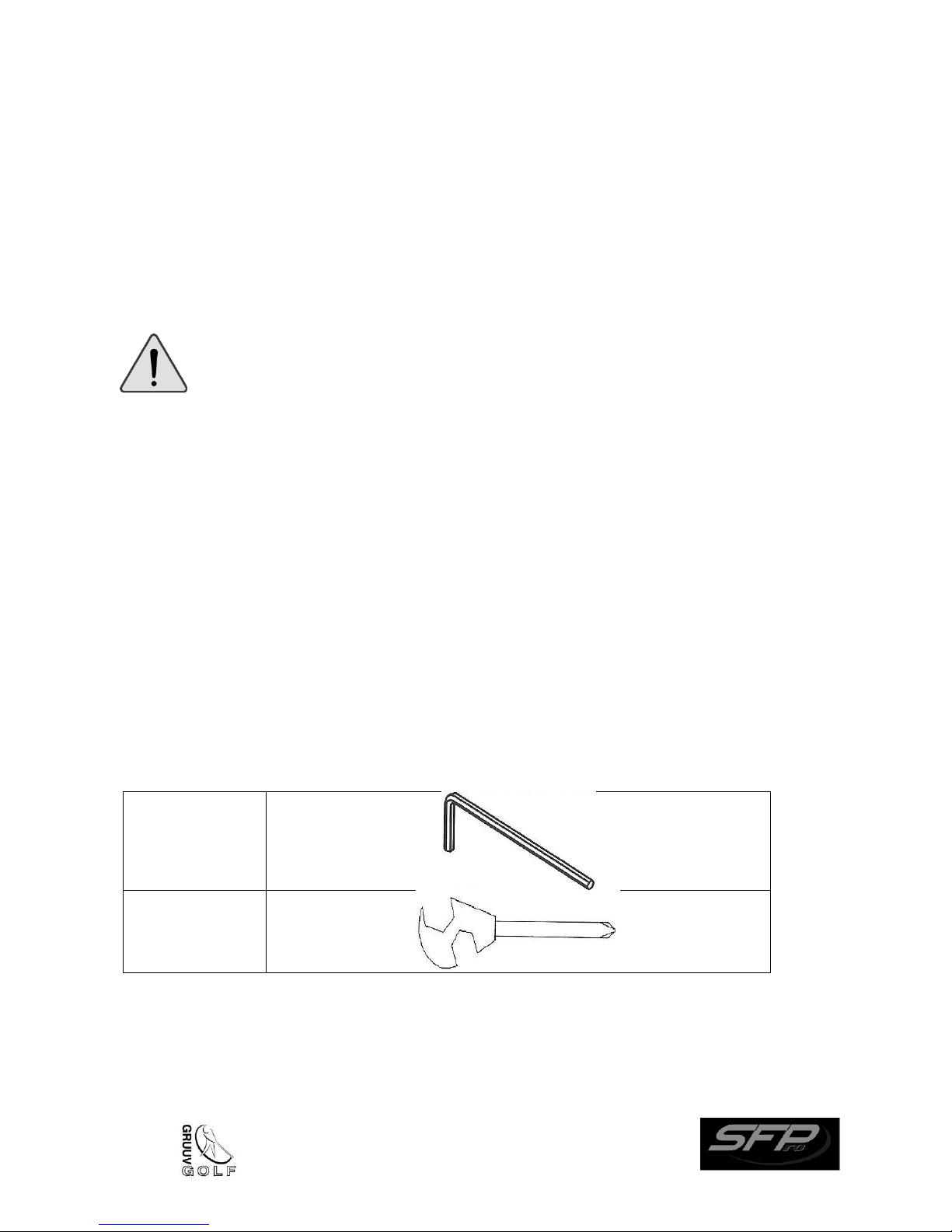
1 Allen Key
1 Wrench
2. Assembling the SFPro
During the assembly process there are several areas that warrant special attention. It is very
important to follow the assembly instructions correctly. If the assembly instructions are not
followed correctly and in proper sequence, there is a risk that the SFPro will not function properly.
To prevent damage to the SFPro and to minimize the risk of harm or injury, it is important to comply
with all the assembly instructions.
WARNING: Do not unpack or assemble the SFPro in the presence of
children unless they are under strict adult supervision.
UNPACKING
Unpack the SFPro close to the area where it will be used. Place the SFPro box on a level flat surface
and ensure you have sufficient space available to spread the SFPro parts as you unpack them. It is
recommended that you place a protective covering on your floor. Take CAUTION when handling
and transporting the box and its contents. Do not open the box when it is on its side.
Pre-Assembly
Unpack all the tools and parts required for assembly that were included in the SFPro box.
During each assembly step, ensure that ALL bolts and nuts are in place and partially threaded in
before completely tightening.
Tools provided:
5
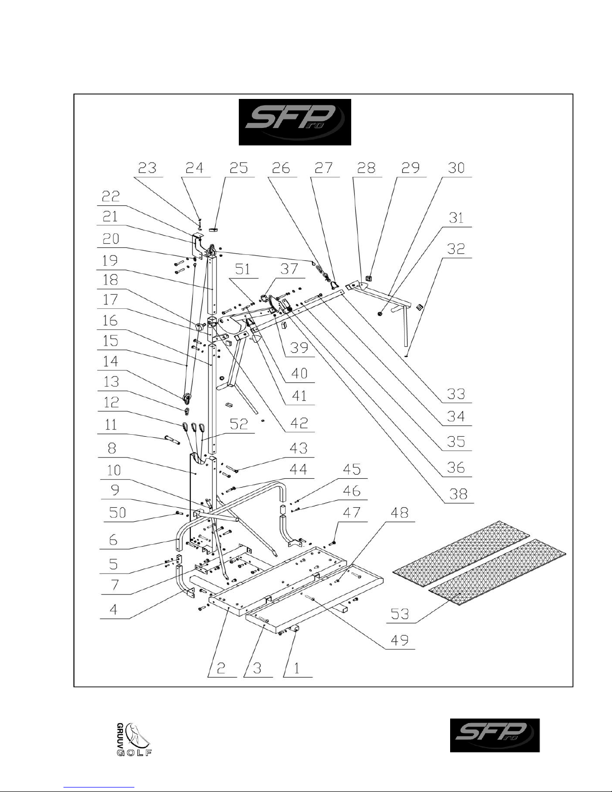
SFPro Parts List Diagram
6

SFPro Parts List Descriptions
Part #
Part Description
Part #
Part Description
1
Platform mount
27
Shoulder bar safety pin
2
Platform rear piece
28
Long handle tightening knob
3
Platform front piece
29
Shoulder bar plastic cap
4
Knee brace mount bottom piece
30
Long handles (left and right)
5
Knee brace mount connector piece
31
Hand size grip
6
Knee brace mount top piece
32
Golf size grip
7
Platform mount rear cross piece
33
Shoulder bar
8
Resistance band mount
34
Bolt (100 mm) – Shoulder bar
9
Knee brace
35
Flat washer
10
Diagonal support braces
36
Yoke bearing assembly
11
Resistance band support tube
37
Angle adjuster tightening knob
12
Resistance band "C" clamps
38
Angle adjuster
13
“C” clamp connector
39
Large white plastic washer
14
Bottom pulley
40
Bolt (50 mm)
15
Resistance cable
41
Raising arm
16
Middle post
42
Raising arm release pin
17
Middle post sleeve
43
Bolt (60 mm)
18
Middle post sleeve tightening knob
44
Bolt (55 mm)
19
Top post
45
Bolt (12 mm)
20
Oval connector
46
Washer
21
Top pulley mount
47
Bolt (35mm)
22
Top pulley
48
Bolt (12 mm)
23
Open hook
49
Bolt (50 mm)
24
Wing nut
50
Bolt (40 mm)
25
Top post plastic cap
51
Nut
26
Snap hook for shoulder bar
52
Resistance bands
53
Carpet
7
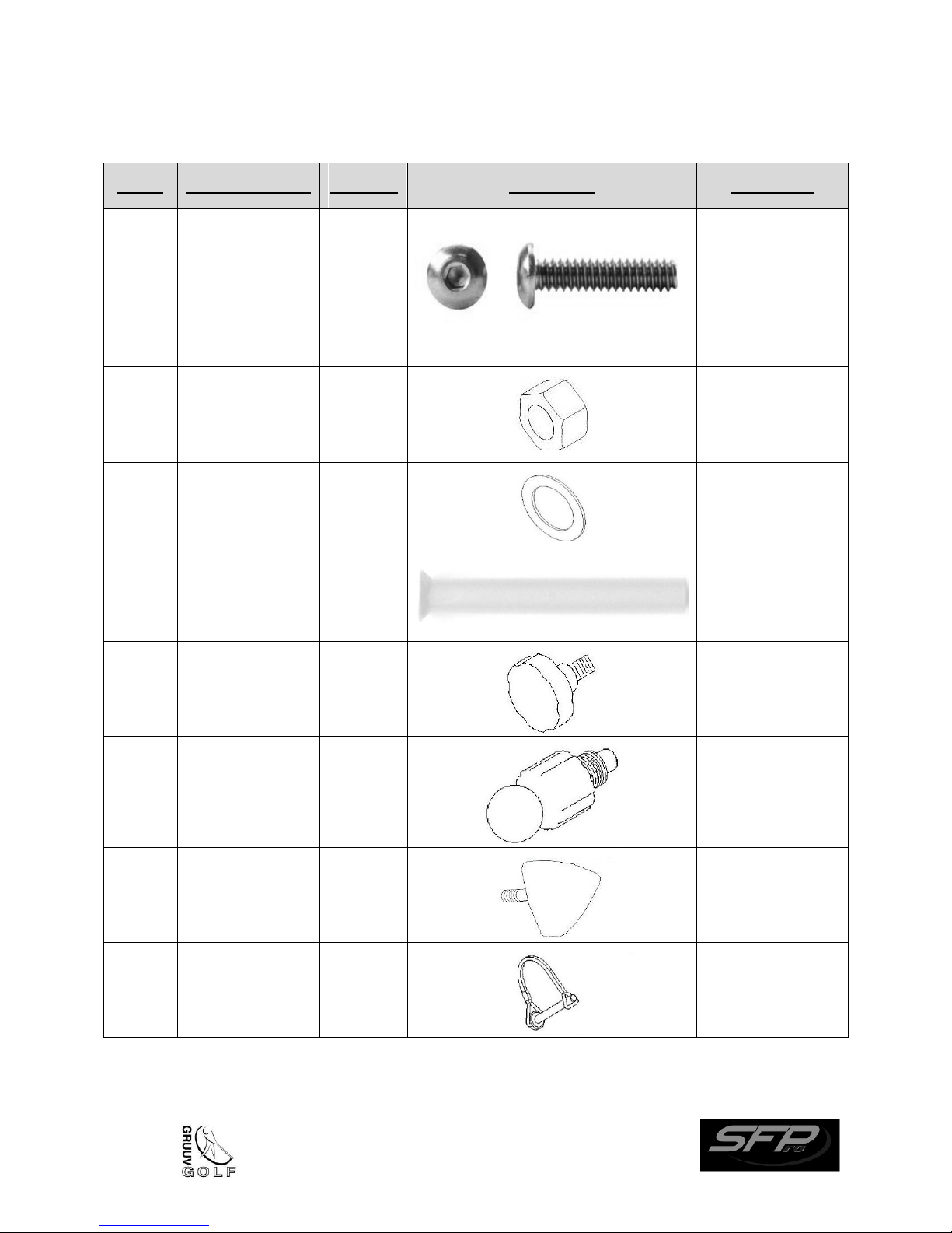
SFPro Illustrated Hardware Parts List for Assembly
Part #
Part Description
Quantity
Illustration
Comments
45, 48
47
50
49
44
43
12 mm bolt
35 mm bolt
40 mm bolt
50 mm bolt
55 mm bolt
60 mm
18
4
1
6
6
1
Generic
illustration, not
representative of
a particular size
or type of SFPro
bolt.
51
Nuts
17
46
Washers
49
11
Resistance band
support tube
1
18 Middle post
sleeve tightening
knob
1
42
Raising arm
release pin
1
28
Long handle
tightening knob
4
27
Shoulder bar
safety pin
2
8
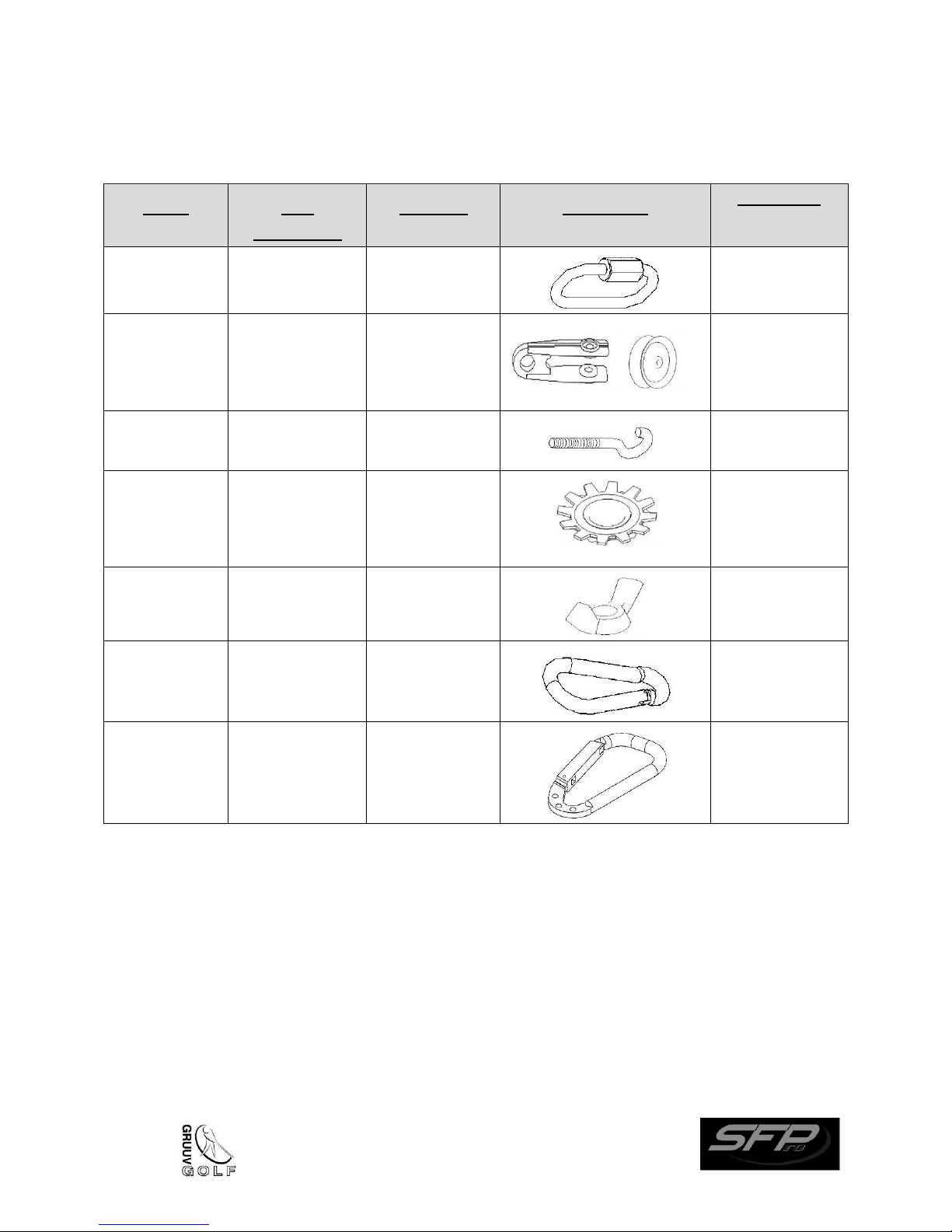
Illustrated Hardware Parts List for Assembly (cont’d)
Part #
Part
Description
Quantity
Illustration
Comments
20
Oval connector
1
14, 22
Top and Bottom
Pulleys
2
Pulley wheel and
clamp come
assembled with
Resistance cable
23
Open hook
1
Part of Open
hook
Gear nut
1
Comes
assembled with
Open hook and
Wing nut
24
Wing nut
1
13
“C” Clamp
connector
2
12
Resistance band
“C” connector
3
9
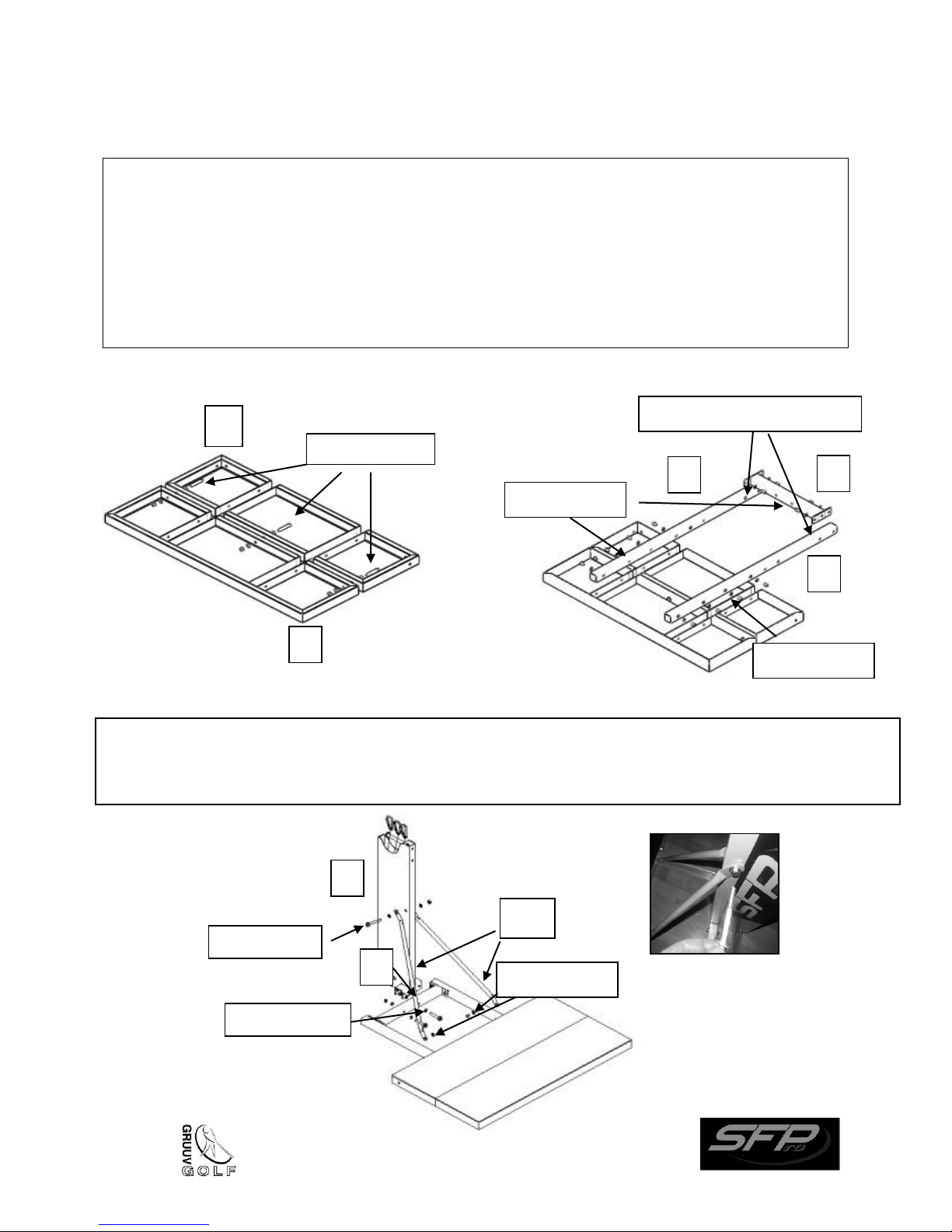
Assembly Step 1
2
3
1
7
1
8
10
50 mm bolts
Holes towards the inside
55 mm bolt
7
55 mm bolts
Attach the Resistance band mount (part 8) to the Platform mount rear crosspiece (part 7) using 55 mm
bolts fastened by nuts and washers
band mount (part 8) using a 55 mm bolt and to the Platform mounts using 12 mm bolts and washers.
12 mm bolts
12 mm bolts
12 mm bolts
A) Turn the Platform rear and front pieces (parts 2 and 3) upside down and secure them together using
a 50 mm bolt fastened with a nut and two washers for each of the three holes.
B) Insert the two Platform mounts (Part 1) into the slots in the assembled front and rear Platform
pieces from step A. Secure the Platform mounts using 12 mm bolts and a washer for each of the
eight holes (four per mount). You must ensure that the portion of the platform mounts that is away
from the platform has the side holes facing towards the inside. Install the platform mount rear cross
piece (part 7) between the two platform mounts as shown using a 12 mm bolt and a washer for
each of the four holes.
A) B)
Assembly step 2:
. Install the Diagonal support braces (part 10) to the Resistance
10
9
11
4
5
6
2
16
12 mm bolts
35 mm bolts
60 mm bolt
A
B
40 mm bolt
8
Install the Middle post (part 16) inside the top of the Resistance band mount (part 8) and secure it first by
into the Resistance band support tube (part 11) through the top hole of the Resistance band mount (A).
Rest the inside of the Resistance
band support tube (C). Ensure that
aligned and do not cross over each
the Resistance band support tube.
55 mm bolt
Assembly Step 3:
Assemble the Knee brace mount (parts 4, 5 and 6) using four 12 mm bolts with washers and
secure it to Platform rear piece (part 2) using four 35 mm bolts and washers. Install the Knee
brace (part 9) onto the Knee brace mount using the 40 mm bolt fastened with a nut (do not
over-tighten to allow for lateral movement of the Knee brace across the Knee brace mount).
Assembly Step 4:
inserting a 55 mm bolt in the lower hole fastened with a nut and two washers; then insert the 60 mm bolt
band loops over the Resistance
the Resistance bands are properly
other once they are installed on
11
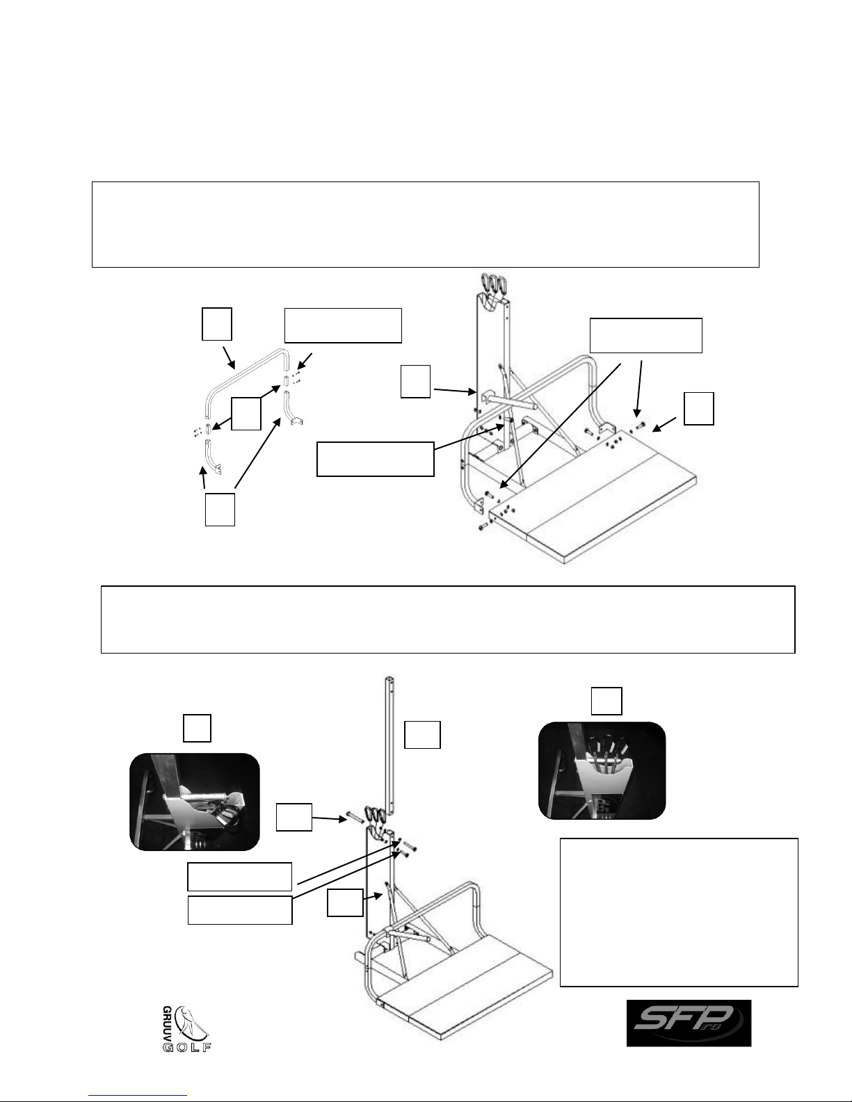
Assembly Step 5:
Install the Middle post sleeve (part 17) onto the Middle post
into a collapsed position and to be returned to the operating
to avoid inadvertent collapse of the Raising arm.
Install the right and left Long handles (part 30) onto the
bar (part 33).
41
30
33
27
17
50 mm bolt
18
Please note: although the
attach these parts together.
33
28
42
16
(part 16) and secure it using the Middle post sleeve
tightening knob (part 18).
Install the Raising arm (part 41) (with Shoulder bar (part 33)
attached) onto the Middle post sleeve using the 50 mm bolt
and the Raising arm release pin (part 42). Do not screw in
the Raising arm release pin all the way – sufficient space
must be afforded to allow the Raising arm to be lowered
position. The Release pin should be screwed in far enough
Shoulder bar (part 33) and the
Raising arm (part 41) are depicted
above as separate parts, they are
factory pre-assembled and no
further assembly is required to
Assembly Step 9:
Assembly Step 6:
Shoulder bar (part 33) and secure using the Long
handle tightening knobs (part 28) insert the Shoulder
bar safety pins (part 27) on both ends of the Shoulder
12
 Loading...