

ITALIAN DESIGN
INSTALLATION, COMMISSIONING, USE AND MAINTENANCE MANUAL
Wall-mounted condensing boiler
Kondens
A brand by G20 ENGINEERING


THEA 65 MN KONDENS MANUAL
08/2017 VERSION - REV.2
G20 Engineering srl estabilished in Loc. Campogrande, 13 - Carpaneto Piacentino whose processes of design,
manufacturing and after-sales service are in compliance with requirements of UNI EN ISO 9001:2008 - DECLARES
that THEA boilers are in compliance with European Directives and with European Delegates regulations.
Chief Executive Marco Rapaccioli
TABLE OF CONTENTS
General requirements 2
-General information 2
-Description of the boiler 3
-Components 3
-Interface description 4
-Main menu 5
-Page 2-Operation 6
-Page 2-Operation-Season select 7
-Page 2-Operation-Temperature
regulation 7
-Information menu 8
-Operation with room
thermostat 9
-Operation with external sensor 9
-Operation with
Opentherm timer thermostat 9
-Operation with storage tank 10
-Faults 12
-Fault codes table 13
Installation 14
-Operational diagram 14
-Cascade installation diagram 14
-Wiring diagram 15
-Installation 16
-Fastening the boiler to the wall 17
-Layout of connections 17
-Plumbing in the boiler 18
-Connecting the condensate line 18
-Connection to the mains
gas supply 19
-Connection to the electrical system 20
-Combustion gas evacuation system 21
-Air intake and combustion gas
evacuation system: important
information 21
Adjustment and maintenance 22
-General maintenance operations 22
-Component replacement 23
-Cleaning the Mixer lter 24
-Power adjustment 26
-Testing the gas supply
dynamic pressure 27
-Heating power adjustament 28
-Analysis - Checking and regulating
combustion 29
-Changing gas type 30
-Accessing the conguration menu 31
-Installer menu 32
-Thermostat installation 34
-Installation of external temp. sensor 35
-External temp. sensor conf. 35
-Auto-learning function 36
-Conguring the climate curve 37
-High-temp systems (SP50°-80°) 37
-Low temp systems (SP28°-57°) 37
-Timer thermostat installation 37
-Special functions 38
-Technical Data 39
EC CONFORMITY DECLARATION (ACCORDING TO ISO/IEC 17050-1)
TABLE OF CONTENTS
GENERAL INFORMATION
GENERAL REQUIREMENTS
This manual, supplied with every boiler, should be considered
as an integral component as it contains instructions for
the correct, safe and appropriate installation, use and
maintenance of the system.
The manual must always be kept by the user of the boiler
and made available for the installation and/or maintenance
technicians to consult. It must also accompany the boiler if it
should be moved or otherwise transferred.
The manufacturer shall not be held responsible for any
damage caused by failure to follow the instructions contained
in this manual, nor:
If the boiler is used for purposes other than those for which
it was built.
If any part or circuit of the boiler is modied.
If accessories or kits not approved by the manufacturer
are installed.
If ordinary and extraordinary maintenance is not performed
by qualied personnel.
If applicable technical and legal requirements have not been
observed during installation and maintenance of the boiler.
WARNING!
If the boiler should cease to function or not function correctly,
deactivate it immediately by turning it off and then shutting
off the gas supply. Do not attempt any repairs or direct work
on the boiler.
Only personnel with the necessary qualications and licenses
must perform maintenance on the boiler. Any repairs must be
performed using only original parts and accessories.
SYMBOLS USED IN THE MANUAL:
Advice, suggestion, note
Important information, indications of methods
and operations which could compromise
correct operation of the boiler and create
a hazard.
CE CERTIFICATES ARE AVAILABLE ON OUR WEBSITE www.produzionecaldaie.it
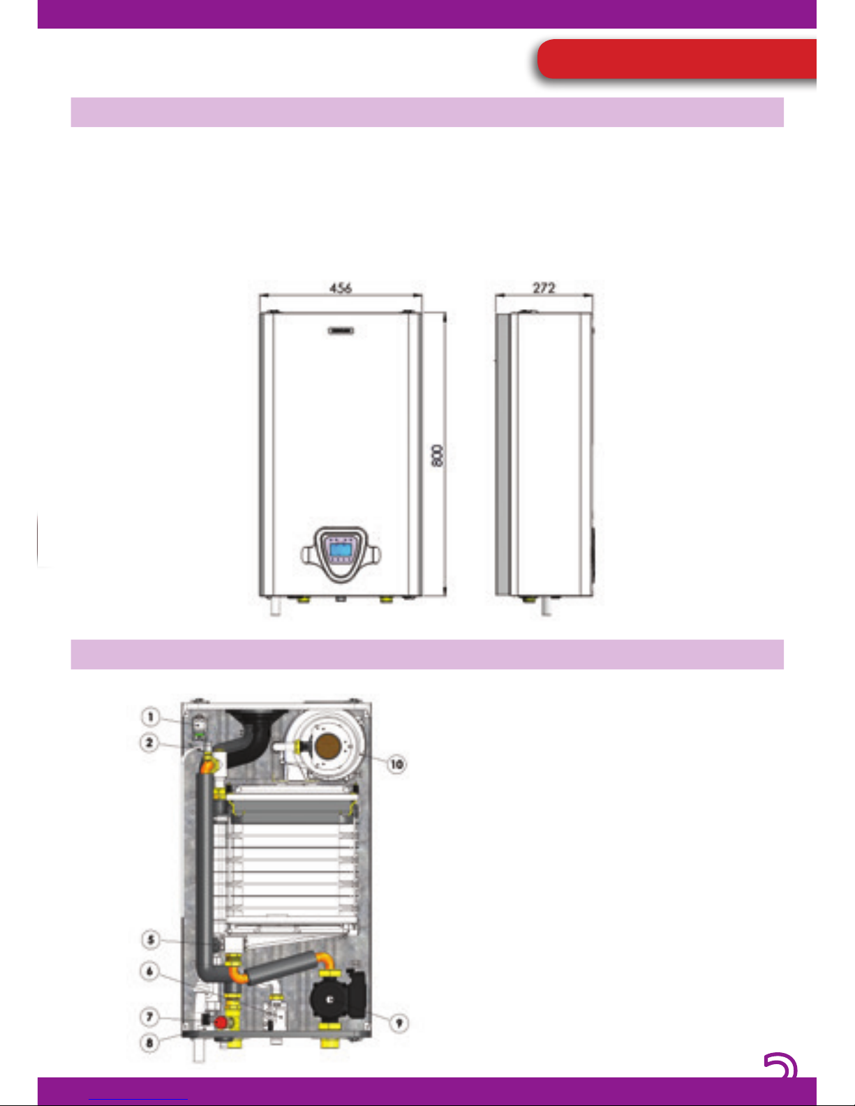
DESCRIPTION OF THE BOILER
COMPONENTS
The Thea range of wall-hung boilers is
completed by the agship model: Thea 65
MN Kondens. A perfect, powerful, reliable
and ecological boiler, it is tted with a highefciency condensing heat-exchanger and
is completely made in Italy.
The boiler includes a PCB with microprocessor
to manage the system in such a way as to
always provide maximum efficiency and
minimum waste.
The highest quality components complete
a system which is essential whenever the
highest levels of domestic comfort and a
clean, elegant and livable environment are
required.
THEA 65 MN Kondens
1) IGNITER
2) DOUBLE HEATING/SAFETY SENSOR
3) -
4) HEAT EXCHANGER
5) PRESSURE TRANSMITTER
6) GAS VALVE
7) SAFETY VALVE
8) PRESSURE GAUGE
9) CIRCULATOR UNIT
10) FAN
Pict. 1
Pict. 2
USE AND OPERATION
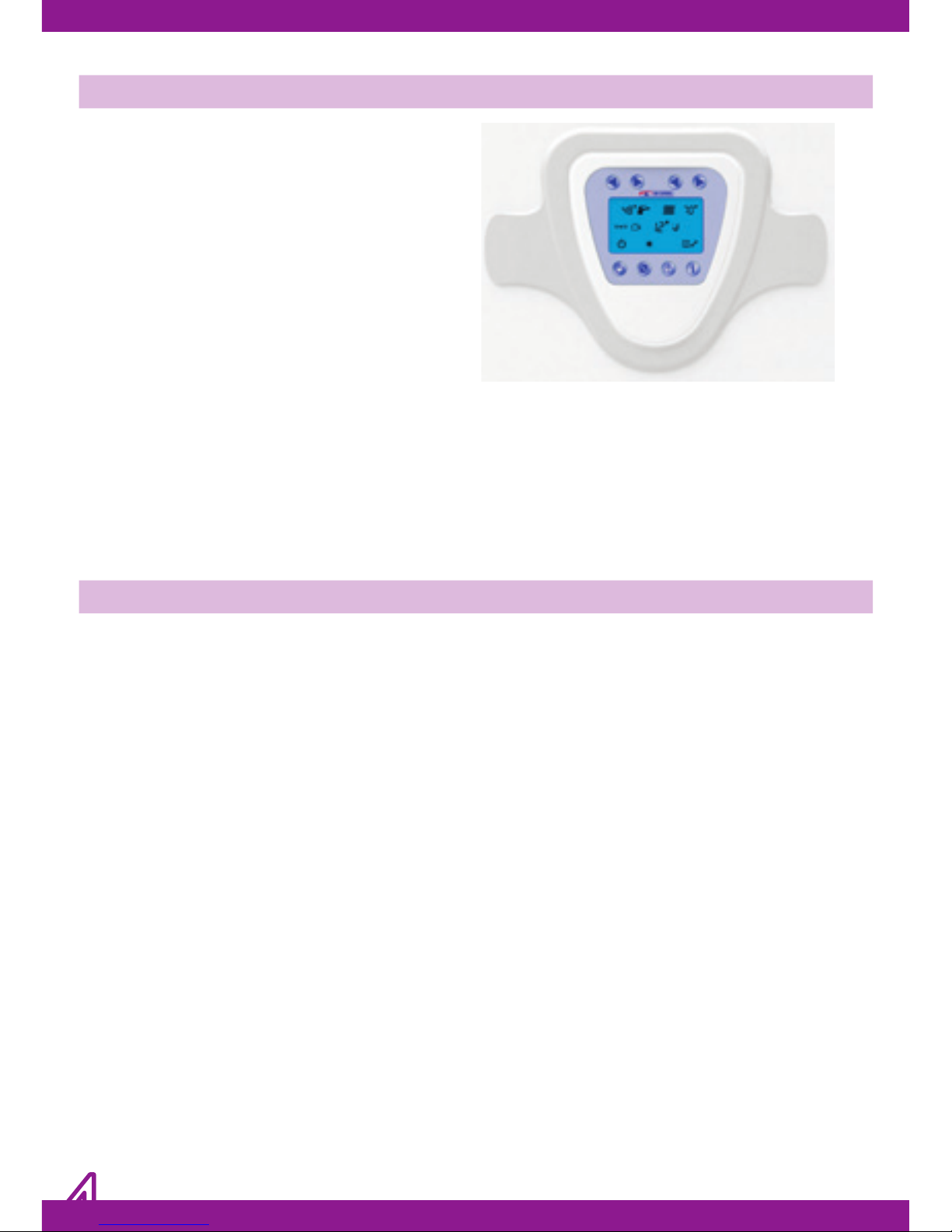
INTERFACE DESCRIPTION
IGNITION
Turn on the boiler’s electrical supply at the
switch, which must be installed on the power
supply line to the boiler. The LCD display (with
blue backlight) will turn on immediately,
showing the two-digit software version
number loaded on the microprocessor for
a few seconds, while an automatic check is
performed on the conditions of the system
and installed devices. When this stage has
nished, if no faults are present, the last page
of the MAIN MENU to be stored is displayed
on the LCD (the one being displayed when
the power was turned off).
The interface allowing all operating parameters
to be selected and modied as well as their
relative values to be displayed is extremely
simple. It is composed of a large backlit
LCD which displays all symbols necessary for
communicating the boiler’s status in a simple
and immediate way, together with a series of
buttons which are matched unequivocally to
a specic function indicated on the display.
Consult the relevant sections to get
explanations on the symbols and the possible
operating modes.
1. ON/OFF BUTTON
2. SUMMER/WINTER BUTTON
3. RESET BUTTON
4. INFORMATION/CONFIGURATION BUTTON
5. DHW TEMPERATURE DECREASE
6. DHW TEMPERATURE INCREASE
7. CH TEMPERATURE DECREASE
8. CH TEMPERATURE INCREASE
1526374
8
Pict. 3
“STAND-BY” MAIN MENU
When the boiler is turned on, two operating
modes are possible. These ones constitute
the MAIN MENU from which it is possible to
set any operating mode required or view the
boiler status at any time. The characteristics
of the possible options for each of the MAIN
MENU pages are given below:
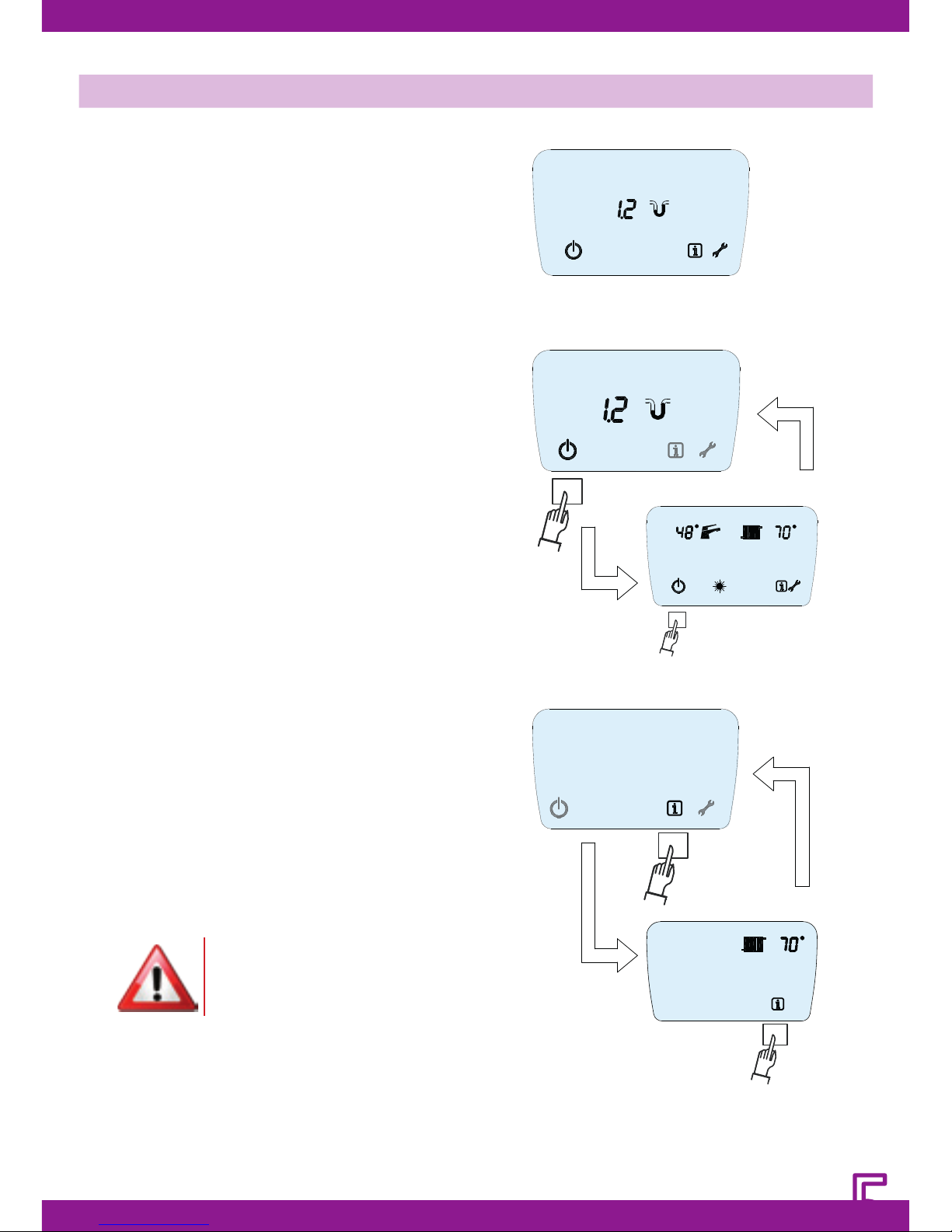
Page 1 – STAND-BY (Pict. 4.1)
In this mode the device is powered on but all
functions regarding the supply of domestic
hot water or central heating are inactive.
In this mode the central heating system
pressure is displayed (in boilers with pressure
transmitter) and the MAIN MENU can be
entered by pressing button 1; to go back to
the starting page (STAND-BY) press button 1
again (Pict. 4.2)
By pressing button 4, the INFORMATION
MENU is accessed; to go back to the starting
page, press button 4 again (Pict. 4.3)
Consult the relevant chapters for menu
exploring and menu functions: “FUNCTION”,
“INSTALLER MENU”.
When in the STAND-BY mode, all fault
indication modes remain active as do the
main maintenance functions for the diverter
valve (when tted) and the circulator unit
together with the ANTI-FROST function.
Pict. 4.1
Pict. 4.2
Pict. 4.3
In standby/off mode the boiler is
inactive but its electricity supply
is still connected!
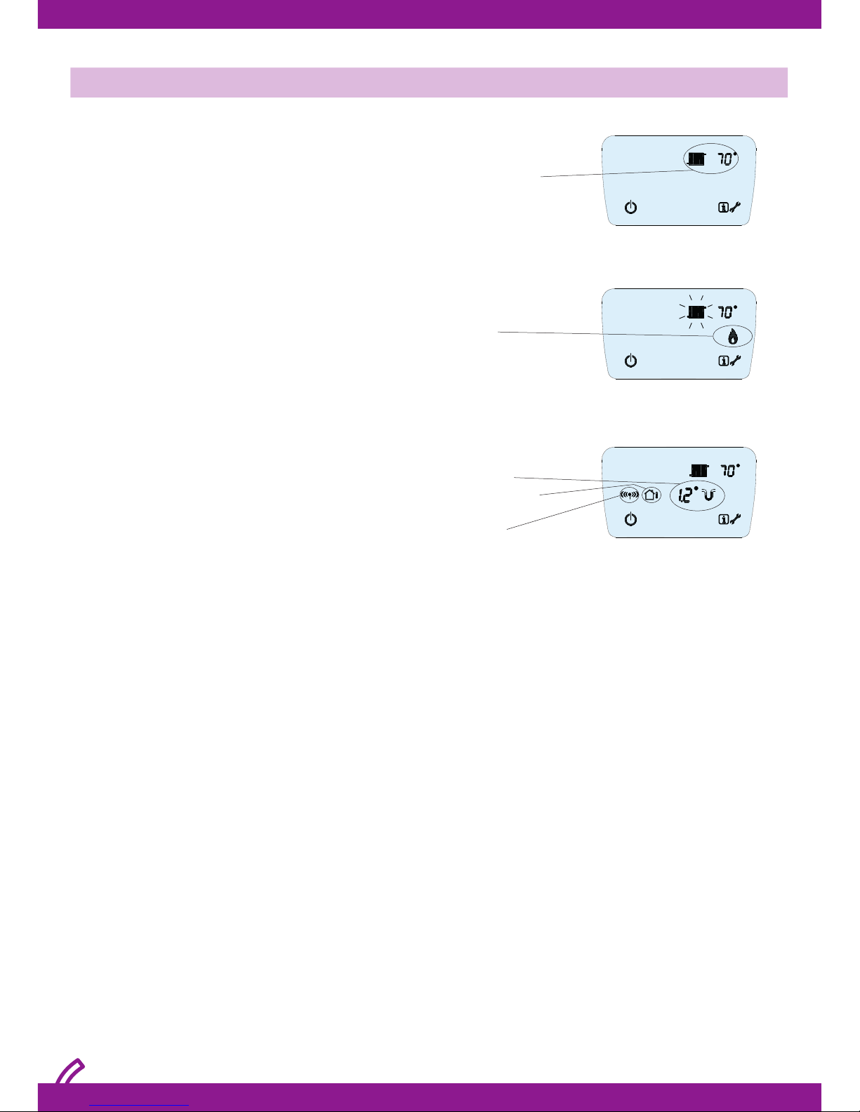
“OPERATION” MAIN MENU
The OPERATION page is the main page which is
always displayed during the normal operation
of the boiler.
In this page, the following symbols are always
displayed:
Central-heating only boilers
• The temperature of hot water in the CH circuit;
• The INFORMATION menu access symbol;
• The INSTALLER menu access symbol;
• The stand-by/off menu access symbol (Pict.
5.1).
When the burner is operating the ame signal
is displayed, with the radiator symbol ashing
(Pict. 5.2). Based on whether devices such
as the pressure sensor, external temperature
sensor and OT timer thermostat are installed,
the following are displayed respectively: the
pressure of the central heating circuit with
relative symbol and the OT timer thermostat
present symbol. (Pict. 5.3).
CH Temperature
System pressure
External temperature
sensor
OT thermostat
remote control
Burner on
Pict. 5.1
Pict. 5.2
Pict. 5.3
The boiler has two operating modes, which
depend on the basic configuration, in
response to the external temperature or
the user requirements. These modes can be
selected from the OPERATION page:
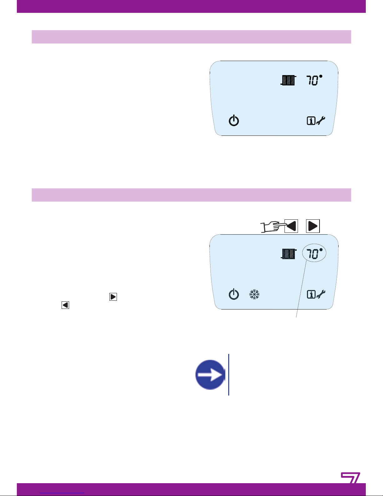
Central-heating only boilers
The season selection option is not available in
central heating only boilers. The device can
therefore be either in stand-by (Pict. 4.1) or
operational, ready to supply the only service
which it has been manufactured for (Pict.6).
PAGE 2-OPERATION-SEASON SELECTION
TEMPERATURE ADJUSTMENT
Pict. 6
Pict. 7
Central-heating only boilers
Only the temperature value for the single
option which can be viewed on the display
can be adjusted in central heating only
boilers.
Central heating temperature setting in the
CH circuit
Push one of the two buttons located above
the RADIATOR symbol (7-8); the set and
displayed CH water temperature value starts
ashing, then push (8) button to increase
and (7) button to decrease. Every button
pressure means 1°C increase/decrease.
Once reached the desired value, do not
press 7-8 buttons anymore; the new water
temperature value ashes for 5 seconds and
it is automatically memorized and displayed.
The temperature values which can be
set depend on the type of system which
the boiler is connected to. For serving
high temperature heating systems, the
temperature range is: min 50°C - max 80°C;
for serving low temperature heating systems,
the temperature range is: min 27°C - max
55°C.
ASK YOUR AREA INSTALLER FOR
INFORMATION ON THE TYPE
OF SYSTEM CONNECTED AND
RESPECTIVE ADJUSTMENTS.
CH temp.
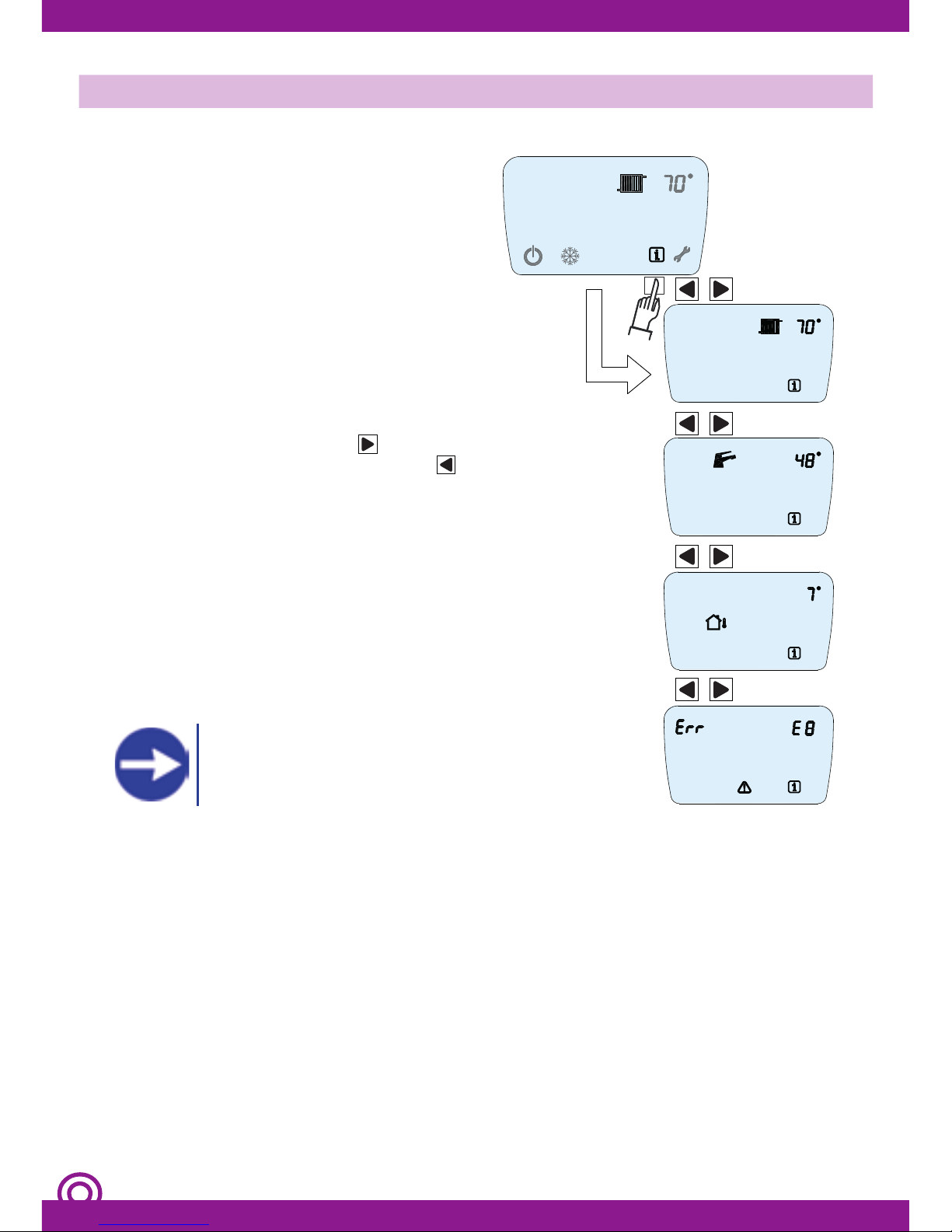
MAIN MENU: INFORMATION MENU
Accessing the INFORMATION MENU allows
various important parameters regarding the
boiler adjustments and status to be viewed,
allowing the state determining its operation
to be known at any time. The displayed
parameters cannot be modied.
Activating the INFORMATION MENU:
To access the menu pages, push button 4.
It is possible to access the INFORMATION
MENU both when the boiler is in standby/off
and in operation.
Selecting the menu pages
In order to display all the parameter values of
INFORMATION MENU, after activating the rst
page which immediately shows the value of
CH water temperature, push 6 button in
order to scroll the pages forwards and 5
button in order to scroll them backwards.
The pages which can be displayed are:
1. Central heating temperature set
2. Domestic hot water temperature set
Pict. 8
REQUEST INFORMATION ON
CONNECTED DEVICES FROM AREA
AUTHORISED INSTALLER
ASK YOUR AREA INSTALLER FOR
INFORMATION ON THE INSTALLATION
AND OPERATION OF A ROOM
THERMOSTAT.
REQUEST INFORMATION ON
INSTALLATION OF THE EXTERNAL
SENSOR AND OPTIMAL
REGULATION OF THE BOILER
FROM YOUR AREA AUTHORISED
INSTALLER.
OPERATION WITH ROOM THERMOSTAT
OPERATION WITH EXTERNAL SENSOR
Energy savings regulations REQUIRE the boiler
to be connected to a room thermostat in
order to optimally regulate and maintain the
temperature in domestic environments.
The boiler can be connected to an external
sensor. In this mode, the system can regulate
the central heating circuit temperature
automatically based on the temperature
measured by the suitably located sensor on
the outside of the building.
Adjustments are made automatically to the
central heating circuit temperature using
a pre-loaded mathematical algorithm.
Different “climate curves” can be selected by
modifying the correct parameters, allowing
the boiler to be optimised for a specific
climatic area or season.
It is possible, in any case, to customise the
central heating circuit temperature using
the MULTIFUNCTION KNOB; increasing or
decreasing the central heating circuit
temperature adapts it (temperature offset)
based on the selected climate curve.
REQUEST INFORMATION ON
INSTALLATION OF THE EXTERNAL
SENSOR AND OPTIMAL
REGULATION OF THE BOILER
FROM YOUR AREA AUTHORISED
INSTALLER.
OPERATION WITH OPENTHERM TIMER THERMOSTAT
For optimum and even more economical
management of the domestic premises
it is possible to use the ECOCHRONO
programmable timer thermostat.
ECOCHRONO allows all main boiler functions
to be managed remotely, allowing it to be
fully managed from a different room to that
where the boiler is installed. ECOCHRONO
can also be used to schedule daily and
weekly room temperatures and manage
reduced demand periods (holidays, anti-frost
and maintenance modes).
AB
B
A
BOILER FLOW
DHW
WATER SUPPLY CIRCUIT
1
2
3
RETURN INTO BOILER
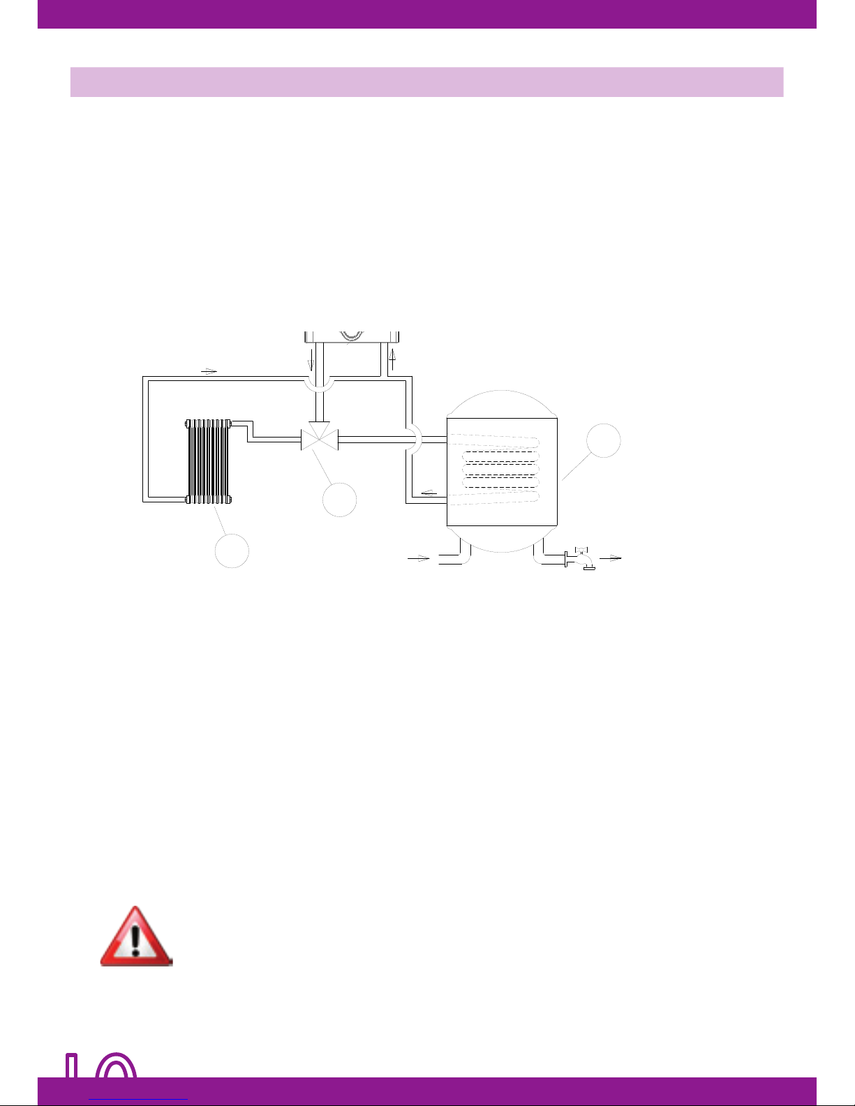
OPERATION WITH STORAGE TANK
Pict. 9
The boiler can manage a DHW storage tank. All the functions which allow a quick installation
and a precise and efcient control of systems for producing and supplying domestic hot
water are available.
HYDRAULIC CONNECTION TO DHW STORAGE TANK
In order to produce domestic hot water by a storage tank, it is necessary to connect the boiler
primary circuit to the storage tank primary circuit. In order to control the DHW management
and production and the heating function, it is necessary to introduce a 3-ways diverting
valve in this hydraulic circuit, so that the DHW and CH functions are activated and used
only when they are needed.
3-WAYS DIVERTING VALVE CONNECTION
The correct system operation depends on the correct diverting valve functioning. Therefore
the correct functioning of the hydraulic connections must be carefully checked before
powering the system on.
The boiler is arranged for supplying the necessary power to activate the 3-ways diverting
valve: AC230V
Inside the control panel a specic connector is there to connect:
1_ the “common” line cable;
2_ the “Open” line cable
3_ the “Closed” line cable
The “Open” and “Closed” modes determine the commutation from DHW (preparation
of DHW storage tank) to CH. Their position depends on the type of diverting valve in use.
THE CONNECTION FOR ACTIVATING THE DIVERTING VALVE ARE POWERED AT
AC230V. MAKE SURE THE CONNECTIONS ARE CARRIED OUT WHEN THE BOILER IS
POWERED OFF.
DIVERTING VALVES WITH ACTUATORS POWERED AT A DIFFERENT VOLTAGE FROM
THE AVAILABLE ONE ARE NOT SUPPORTED.
1) CH circuit
2) 3-ways valve
3) Storage tank
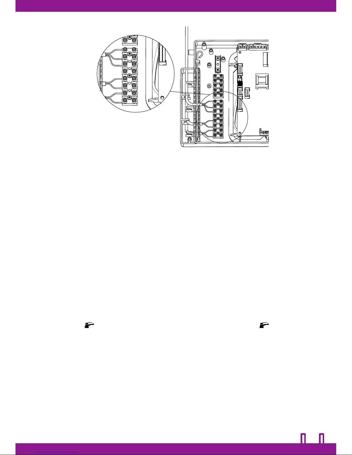
CONNECTION TO DHW STORAGE TANK
DHW Storage with temperature control by NTC sensor
The boiler is arranged to be connected to a DHW storage tank supplied with a NTC sensor
for a continuous DHW temperature control.
In order to connect the sensor, the terminal board inside the control panel must be accessed
and the sensor cable terminals must be connected to the corresponding clips. NTC sensors
are compatible with BETA ones = 3435-10K at 25°C.
DHW Storage with temperature control by thermostat
The boiler is arranged to be connected to a DHW storage tank supplied with a thermostat
for the DHW temperature setting and adjusting.
In order to connect the thermostat, the terminal board inside the control panel must be
accessed and the thermostat cable terminals must be connected to the corresponding
clips. The compatible thermostatic contact is at low tension (clean contact).
After the hydraulic and electrical connections have been effected, all the temperature
control devices have to be connected.
In order to activate the DHW option with storage, the parameter A0=1 must be set from
the installer menu.
After the DHW option has been activated, the NTC sensor/thermostat has to be activated,
by selecting respectively the parameter A18=0 (sensor) / A18=1 (thermostat) from the
installer menu.
The boiler is ready to operate according to the available devices; in DHW mode, the display
will show the symbol and its set point temperatures (sensor) or the symbol only
(thermostat).
The request for DHW by storage tank has the priority towards the request for CH.
The presence of the NTC sensor for the DHW temperature control allows to select, by the
multifunction knob, the desired DHW work temperature.
ADJUSTMENT
While in DHW mode, by the A9 and A10 parameters from the installer menu it is possible to
adjust:
- The primary circuit temperature during the preparation for the storage tank;
- The temperature difference between set point (set sensor) and the temperature detected
by the DHW (only NTC sensor mode) for the burner ignition and switch off (isteresis).
Pict. 10
-
COM.
N.O.
N.C.
STORAGE
TANK
SENSOR
STORAGE
TANK
THERMOSTAT
220 VDC
3-WAYS VALVE
FAULTS
All functions supported by the boiler are
managed by a microprocessor-based system
which, aside from allowing the system to run
perfectly in order to maintain the greatest
level of comfort possible, constantly monitors
the functional parameters, ensuring they fall
within the necessary safety interval by a wide
margin, and therefore that all devices present
are functioning perfectly.
Whenever the malfunction of any component
or conditions which could compromise safe
operation of the system are detected, the
microprocessor system places the device
into a limited operation mode or even
completely prevents it from operating. The
microprocessor system is able to detect and
issue warnings for the main fault conditions
to allow the system to be brought back to
normal conditions as soon as possible. Fault
warnings are given on the LCD display. The
malfunction is detected and an intermittent
warning displayed immediately, consisting
of a number preceded by the error symbol
E and by the relevant fault symbol (Pict. 11).
Faults are displayed on any screen of the
main menu.
Conditions causing transitory faults are
possible. Many of these are recognized
and cause a temporary block which is
automatically reset once the condition
causing the fault has stopped. Some of these
provide for the possibility to attempt to restore
operation manually.
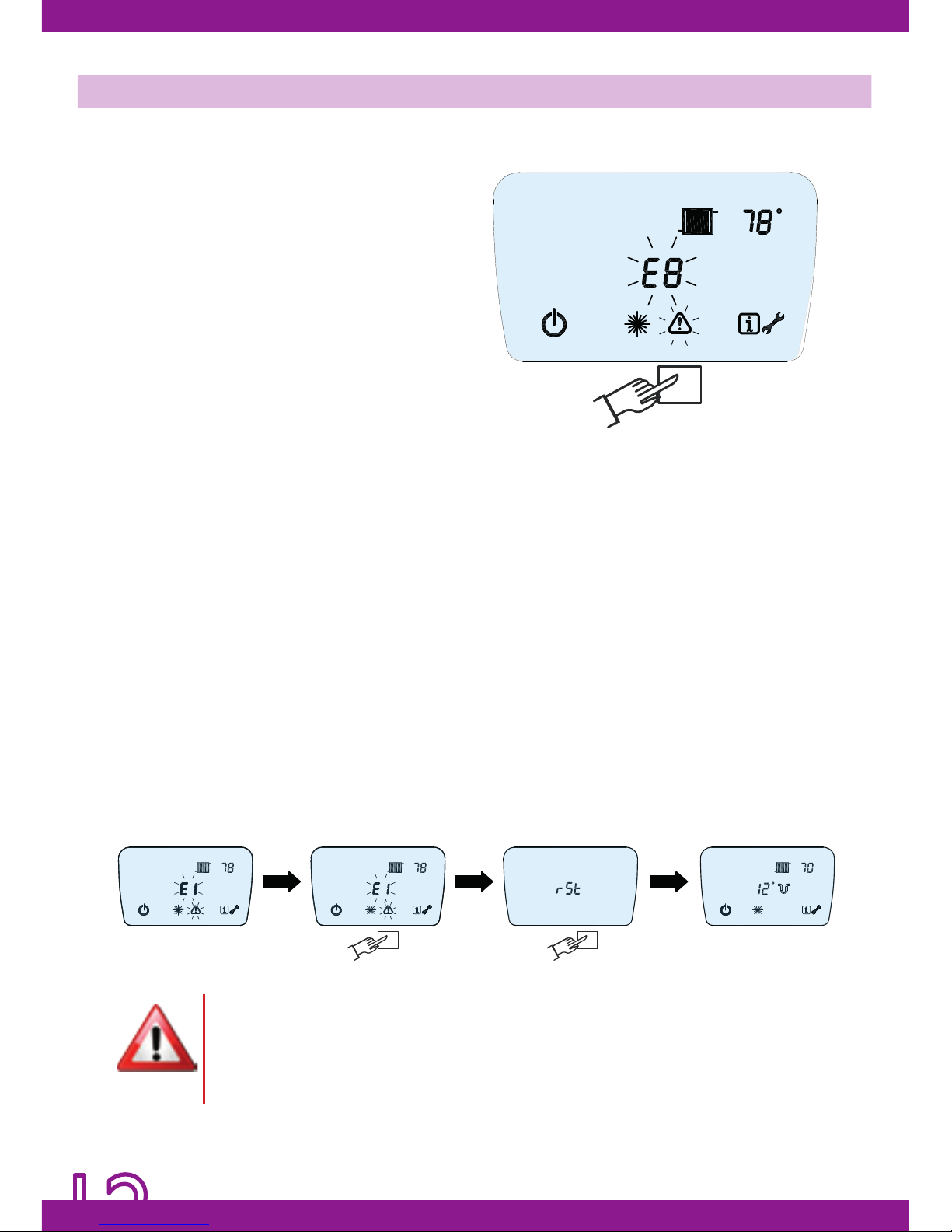
Manual error reset, recovery attempt
To manually reset the system following a
fault condition, press the button 3: the RST
symbol (reset) will be displayed on the
LCD display. Press button 3 again (Pict. 12).
The microprocessor will attempt to recover
the system by resetting all the conditions
presumed to have caused the fault. If the
operation is successful the boiler will return
to normal operation; if not, the error code
causing the malfunction will be displayed
again.
Pict. 12
Pict. 11
IF A FAULT IS NOT SOLVED AFTER 2 MANUAL RESET ATTEMPTS THEN THE AUTHORISED
TECHNICAL ASSISTANCE CENTRE MUST BE CALLED.
TAMPERING WITH ANY DEVICE MAY BE DANGEROUS AND ANNULS EVERY WARRANTY
CONDITIONS.
 Loading...