

ITALIAN DESIGN
INSTALLATION, COMMISSIONING, USE AND MAINTENANCE MANUAL
Wall-mounted boiler with plate heat exchanger
Monothermal
A brand by G20 ENGINEERING


IVY 24/28/32 KW MR/MN
MONOTHERMAL BOILER MANUAL
VERS. 11/2017 - REV.3

CONTENTS
General requirements 2
-General Information 2
Use and operation 3
-Description of the boiler 3
-Components 3
-Ignition 4
-Interface description 4
-“Stand-by” main menu 5
-Function main menu 6
-Season selection main menu 7
-Temperature regulation 7
-Information menu 8
-Operation with room thermostat 9
-Operation with external sensor 9
-Faults 10
-Fault codes table 11
Installation 12
-Operational diagram 12
-Three-way boiler functional diagram 12
-Wiring diagram 13
-Graphs for the head available to the system 14
-Installation 14
-Fastening the boiler to the wall 15
-Layout of connections 16
-Plumbing the boiler 17
-Connecting CH lling cock 17
-Filling the system 17
-Connection to the gas supply 18
-Connection to the electrical system 19
-Combustion gas evacuation and air intake system:
compatible applications 20
-Combustion gas evacuation and air intake system:
installation 21
-Checking the effectiveness of combustion
gas evacuation 23
-Combustion gas evacuation circuit diaphragms 23
-Combustion gas evacuation system: warnings 24
Adjustment and maintenance 25
-Preliminary maintenance operations 25
-General maintenance operations 25
-SERVICE function 25
-Power adjustment 27
-Gas pressure check 28
-Checking the pressure at the burner 28
-Checking mains gas supply dynamic pressure 29
-Checking pressure at burner at max power 30
-Changing gas type 30
-Conguring the software for a change gas type 31
-Access to conguration menu 32
-Installer menu 33
-Information menu 34
-Room Thermostat/Opentherm installation 35
-Installation of external temperature sensor 36
-External temperature sensor conguration 36
-Conguring the climate curve 37
-Special functions 38
-Thermostat post ventilation function 39
-Technical Data Sheet 40
GENERAL INFORMATION
This manual, supplied with every boiler, should be
considered as an integral component as it contains
instructions for the correct, safe and appropriate
installation, use and maintenance of the system.
The manual must always be kept by the user of
the boiler and made available for the installation
and/or maintenance technicians to consult. It must
also accompany the boiler if it should be moved
or otherwise transferred.
The manufacturer shall not be held responsible
for any damage caused by failure to follow the
instructions contained in this manual, nor:
If the boiler is used for purposes other than those
for which it was built
If any part or circuit of the boiler is modied
If accessories or kits not approved by the
manufacturer are installed
If ordinary and extraordinary maintenance is not
performed by qualied personnel
If applicable technical and legal requirements
have not been observed during installation and
maintenance of the boiler.
WARNING!
If the boiler should cease to function or not function
correctly, deactivate it immediately by turning it off
and then shutting off the gas supply. Do not attempt
any repairs or direct work on the boiler.
Only personnel with the necessary qualications
and licenses must perform maintenance on the
boiler. Any repairs must be performed using only
original parts and accessories.
SYMBOLS USED IN THE MANUAL
Advice, suggestion, note
Important communications, signaling
of modes and operations which could
compromise the correct operation
of the boiler and endanger people.
EC CONFORMITY DECLARATION (ACCORDING TO ISO/IEC 17050-1)
GENERAL REQUIREMENTS
G20 Engineering srl estabilished in Loc. Campogrande, 13 - Carpaneto Piacentino whose processes of design,
manufacturing and after-sales service are in compliance with requirements of UNI EN ISO 9001:2008 - DECLARES
that THEA boilers are in compliance with European Directives and with European Delegates regulations.
Chief Executive Marco Rapaccioli
DESCRIPTION OF THE BOILER
COMPONENTS
The Ivy range of boilers represents the best
appliances available for domestic central
heating and hot water production. Their
essential but extremely modern and
elegant lines, compact size, solidity,
performance, reliability and safety place
Ivy boilers in the category of appliances
which are indispensable in every home. In
creating the Ivy range of boilers we chose
to design a system which could satisfy a
wide range of needs, able to adapt itself
to any situation and thus enlarging its
eld of application. Models ranging from
24 to 32 kW power output are indeed
available. The exibility of the Ivy range of
boilers is also increased by the possibility
to congure the management program
of the microprocessor tted to the system.
This allows to pass from a reduced number
of functions and configurations which
make using the device easy, immediate
and effective to a complete conguration
with many specic options enabled as
well as the possibility to interface with
external control and regulation devices.
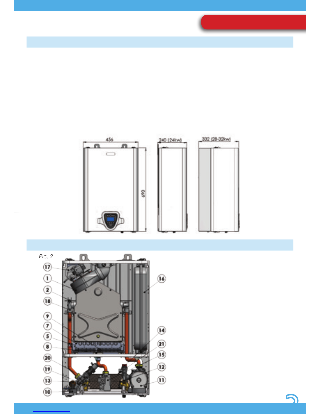
Ivy MR (whit rapid heat exchanger)
1) FUME EXTRACTOR
2) SAFETY THERMOSTAT
5) HEATING SENSOR
7) BURNER
8) IGNITION MONOELECTRODE
9) EARTH ELECTRODE
10) PRESSURE GAUGE
11) CIRCULATOR UNIT
12) DHW PRIORITY VALVE
13) PRESSURE SENSOR (TRANSMITTER)
14) SAFETY VALVE
15) GAS VALVE
16) EXPANSION TANK
17) COMBUSTION GAS PRESSURE SWITCH
18) PRIMARY HEAT EXCHANGER
19) IMMERSION DHW SENSOR
20) THREE-WAYS GROUP
21) SECONDARY HEAT EXCHANGER
Pic. 1
Pic. 2
USE AND OPERATION
152
63748
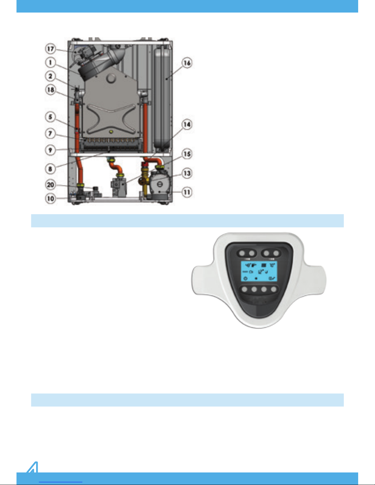
INTERFACE DESCRIPTION
IGNITION
Turn on the boiler’s electrical supply at the
switch, which must be installed on the power
supply line to the boiler. The LCD display (with
blue backlight) will turn on immediately,
showing the two-digit software version
number loaded on the microprocessor for
a few seconds, while an automatic check is
performed on the conditions of the system
and installed devices. When this stage
has nished, if no faults are detected, the
last page of the MAIN menu to be stored
is displayed on the LCD (the one being
displayed when the power was turned off).
The interface allowing all operating parameters to
be selected and modied as well as their relative
values to be displayed is extremely simple. It is
composed of a large backlit LCD which displays all
symbols necessary for communicating the boiler’s
status in a simple and immediate way, together
with a series of BUTTONS each one having a specic
function shown on the display.
Read the relevant chapters for more information
about the symbols and the available operation
modes.
IVY MN (Heat only)
1) FUME EXTRACTOR
2) SAFETY THERMOSTAT
5) HEATING SENSOR
7) BURNER
8) IGNITION MONOELECTRODE
9) EARTH ELECTRODE
10) PRESSURE GAUGE
11) CIRCULATOR UNIT
13) PRESSURE SENSOR (TRANSDUCER)
14) SAFETY VALVE
15) GAS VALVE
16) EXPANSION TANK
17) COMBUSTION GAS PRESSURE SWITCH
18) PRIMARY HEAT EXCHANGER
Pic. 3
1. ON/OFF BUTTON
2. SUMMER/WINTER BUTTON
3. RESET BUTTON
4. INFO/CONFIGURATION BUTTON
5. DHW TEMPERATURE DECREASE
6. DHW TEMPERATURE INCREASE
7. CH TEMPERATURE DECREASE
8. CH TEMPERATURE INCREASE
Pic. 4
“STAND-BY” MAIN MENU
When the boiler is turned on, two operating
modes are possible. These constitute the
MAIN MENU from which it is possible to set
any operating mode required or view the
boiler status at any time. The characteristics
of the possible options for each page of the
MAIN MENU are here listed:
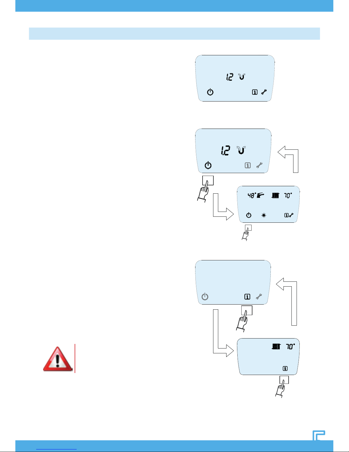
Page 1 – STAND-BY (Pic. 5.1)
In this mode the device is powered but all
functions regarding the supply of domestic
hot water or central heating are inactive. In
this mode the central heating system pressure
is displayed (in boilers with transducer) and
it is possible to turn the boiler on by pressing
BUTTON 1, at the MAIN MENU page :
In order to go back to the rst page (standby), press again BUTTON 1. (Pic. 5.2)
By pressing BUTTON 4, the INFORMATION
MENU can be accessed; by pressing BUTTON
4 again, the rst page is displayed (Pict. 5.3).
Read the relevant chapters for more
information about the functions in each
menu: “FUNCTION, PARAMETERS MENU”
While in the stand-by mode, all fault
indication modes remain active as do the
main maintenance functions for the diverter
valve (when tted) and the circulator unit
together with the ANTI-FROST function.
Pic. 5.1
Pic. 5.2
Pic. 5.3
WARNING: In standby/off
mode the boiler is inactive
but its electricity supply is still
connected!
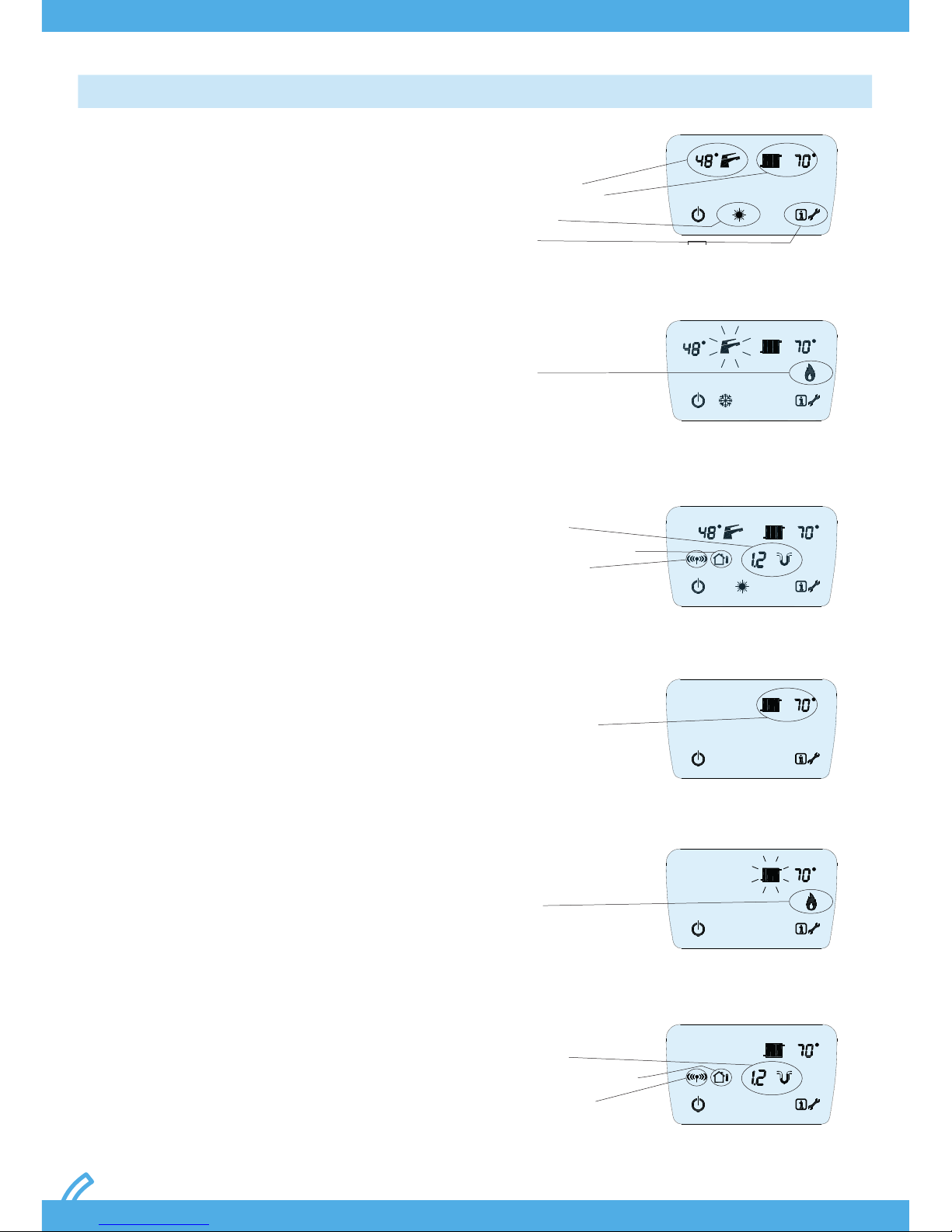
“FUNCTION” MAIN MENU
The FUNCTION page is always displayed during
the normal operation of the boiler. Symbols
regarding the following items are always
displayed:
Boilers for domestic hot water production
• The selected season
• The DHW temperature set
• The temperature of the water in the CH circuit
• The INFORMATION menu access symbol
• The INSTALLER menu access symbol
• The standby/off menu access symbol (Pic. 6.1).
When the burner is lit and running in order to
produce domestic hot water, the tap symbol
ashes and the temperature of the supplied
domestic hot water is displayed. During heating
of the CH circuit water, the radiator symbol
and the CH temperature ash. In both cases,
the ame symbol is always displayed (Pict. 6.2).
Based on whether devices such as the pressure
sensor, external temperature sensor and OT
timer thermostat are installed, the following
are displayed, respectively: the pressure of the
central heating circuit with relative symbol, the
external sensor present symbol and the OT timer
thermostat present symbol. (Pic. 6.3).
Boilers for central heating only
• The temperature of the water in the CH circuit
• The INFORMATION menu access symbol
• The standby/off menu access symbol (Pic. 6.4).
When the burner is operating the ame signal
is displayed, with the radiator symbol ashing
(Pict. 6.5). Based on whether devices such
as the pressure sensor, external temperature
sensor and OT timer thermostat are installed,
the following are displayed respectively: the
pressure of the central heating circuit with
relative symbol and the OT timer thermostat
present symbol. (Pic. 6.6).
Pic. 6.1
DHW temperature
CH water temperature
Season select
Info Menu
Heating temperature
Pressure sensor
External temperature sensor
OT timer thermostat
Pressure sensor
External temperature sensor
OT timer thermostat
Burner on
Burner on
Pic. 6.2
Pic. 6.3
Pic. 6.4
Pic. 6.5
Pic. 6.6
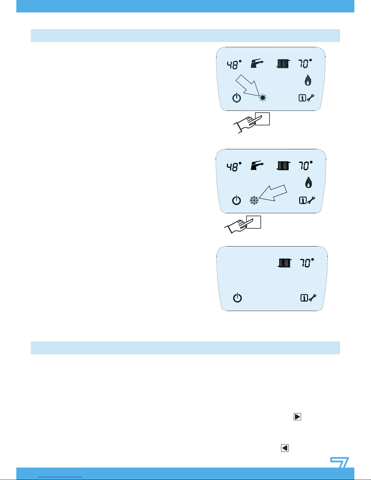
The boiler has two operating modes, which
depend on the basic conguration, in response to
the external temperature or the user requirements.
These modes can be selected from the FUNCTION
page:
Boilers for domestic hot water production
• SUMMER mode deactivates all central heating
functions, maintaining only domestic hot water
production. When the boiler is in this mode the SUN
symbol is displayed on the function page (Pict. 7.1)
• WINTER mode, in which all central heating
and domestic hot water production functions
are active. When the boiler is in this mode the
SNOWFLAKE symbol is displayed on the function
page (Pict. 7.2)
In order to select one of the modes above, press
BUTTON 2.
Boilers for central heating only
The season selection option is not available in
central heating only boilers. The device can
therefore be either in stand-by mode (Pict. 5.1)
or in operational mode, i.e. ready to supply the
only service which it has been manufactured for
(Pict. 7.3).
SEASON SELECTION
TEMPERATURE REGULATION
Pic. 7.1
Pic. 7.2
Pic. 7.3
Boilers for domestic hot water production
It is possible to regulate the temperature
of the domestic hot water supplied as well
as that for the central heating. The set
temperature will be reached, if possible,
when supplying these services and
maintained at the set value, allowing the
user requests to be satised in both cases.
The temperature supplied for both modes
is continuously displayed near the relative
symbol when the functions are active: the
radiator for the central heating and the tap
for domestic hot water.
When the boiler is in standby the DHW
temperature displayed is the set value.
Setting DHT temperature
Press one of the two buttons upon the tap
symbol (5-6). The numbers indicating the
temperature ash, then press the button
(6) to increase the temperature of DHW.
Each time this button is pressed, an increase
by 1°C is obtained. In order to decrease the
DHW temperature, press the button (5).

Each time this button is pressed, a decrease
by 1°C is obtained.
Once the needed temperature value is
set, do not press the (5-6) buttons anymore.
The new DHW temperature value will ash
for 5 seconds, then it will be stored and
displayed.
The minimum hot water temperature which
can be set is 30°C, the maximum 60°C.
Setting CH temperature
PPress one of the two buttons upon the tap
symbol (7-8). The numbers indicating the
temperature ash, then press the button
(8) to increase the temperature of CH. Each
time this button is pressed, an increase by
1°C is obtained. In order to decrease the CH
temperature, press the button (7). Each
time this button is pressed, a decrease by
1°C is obtained.
Once the needed temperature value is
set, do not press the (7-8) buttons anymore.
The new CH temperature value will ash
for 5 seconds, then it will be stored and
displayed.
The CH temperature values depend on the
type of installation.
For boilers used for high temperature
systems, the temperature range is 50°C –
80°C, while for the ones used for low teZ
mperature systems, the temperature range
is 27°C – 55°C.
Setting heating temperature
If the “Summer” mode is active (the
sun symbol is displayed), the device for
modifying the CH temperature is disabled.
Boilers for central heating only
Only the temperature value for the single
option which can be viewed on the
display can be adjusted in central heating
only boilers. Setting the central heating
temperature is performed as previously
described.
DHW temperature CH temperature
Pic. 8
THE USE OF TOO HIGH DHW
TEMPERATURES CAUSES THE
PREMATURE WEAR OF THE DHW
HEAT EXCHANGER.
ASK YOUR AREA INSTALLER FOR
INFORMATION ON THE TYPE
OF SYSTEM CONNECTED AND
RESPECTIVE ADJUSTMENTS
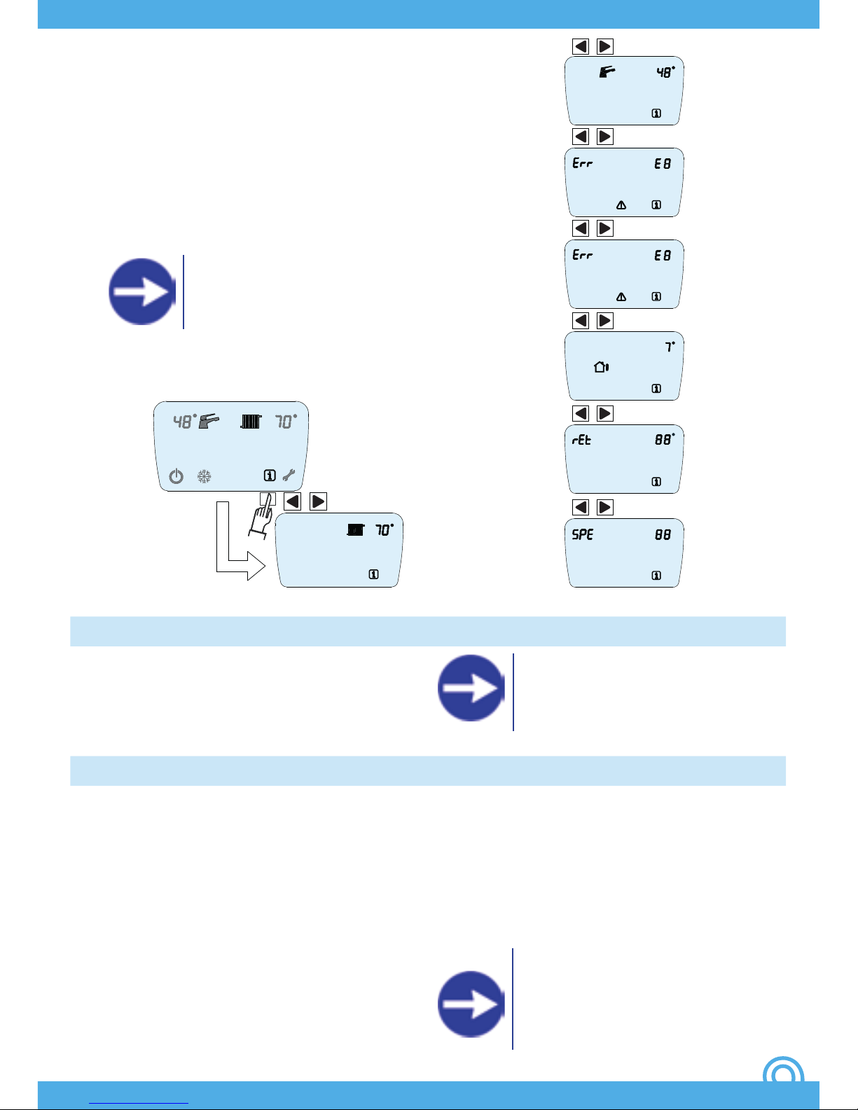
INFORMATION MENU
Accessing the INFORMATION MENU allows
various important parameters regarding the
boiler adjustments and status to be viewed,
allowing the state determining its operation
to be known at any time. The displayed
parameters cannot be modied.
To access the menu pages, press BUTTON 4.
The menu can be accessed both when the
boiler is in stand-by and when it is operating.
Selecting the menu pages
In order to visualize the values of all the
INFORMATION MENU parameters, after
activating the initial page which immediately
displays the central heating temperature,
press the
button (6) to scroll forward the
pages and press the
button (5) to scroll
backward the pages. The pages which can
be displayed are:
1. CH temperature
2. DHW temperature
3. Last error code
4. Second to last error code
5.Temperature measured by external
temperature sensor (if present*)
REQUEST INFORMATION ON
CONNECTED DEVICES FROM AREA
AUTHORISED INSTALLER
ASK YOUR AREA INSTALLER
FOR INFORMATION ON THE
INSTALLATION AND OPERATION
OF A ROOM THERMOSTAT.
REQUEST INFORMATION ON
INSTALLATION OF THE EXTERNAL
SENSOR AND OPTIMAL REGULATION
OF THE BOILER TO YOUR AUTHORISED
AREA INSTALLER.
OPERATION WITH ROOM THERMOSTAT
OPERATION WITH EXTERNAL SENSOR
Energy savings regulations REQUIRE
the boiler to be connected to a room
thermostat in order to optimally regulate
and maintain the temperature in domestic
environments.
The boiler can be connected to an EXTERNAL
sensor. In this mode, the system can regulate
the central heating circuit temperature
automatically based on the temperature
measured by the suitably located sensor on
the outside of the building.
Adjustments are made automatically to the
central heating circuit temperature using
a pre-loaded mathematical algorithm.
Different “climate curves” can be selected by
modifying the correct parameters, allowing
the boiler to be optimized for a specific
climatic area or season.
It is possible, in any case, to customize the
central heating circuit temperature; by
increasing or decreasing the central heating
circuit temperature, the temperature itself
(temperature offset) adapts to the selected
climate curve.
6. Return sensor temperature
7. Fan Speed
The automatic exit from the menu happens
after 60 seconds of device inactivity, or by
pressing any button.
The display will return to last menu page
active when the INFORMATION MENU was
accessed.
Fig. 9
Fig. 9
“1”
“3”
“2”
“4”
“5”
“6”
“7”
FAULTS
OPERATION WITH OPENTHERM TIMER THERMOSTAT
All functions supported by the boiler are
managed by a microprocessor-based system
which, aside from allowing the system to run
perfectly in order to maintain the greatest
level of comfort possible, constantly monitors
the functional parameters, ensuring they
fall within the necessary safety interval by a
wide margin, and therefore that all devices
present are functioning perfectly.
Whenever the malfunction of any component
or conditions which could compromise safe
operation of the system are detected, the
microprocessor system places the device
into a limited operation mode or even
completely prevents it from operating. The
microprocessor system is able to detect and
issue warnings for the main fault conditions
to allow the system to be brought back to
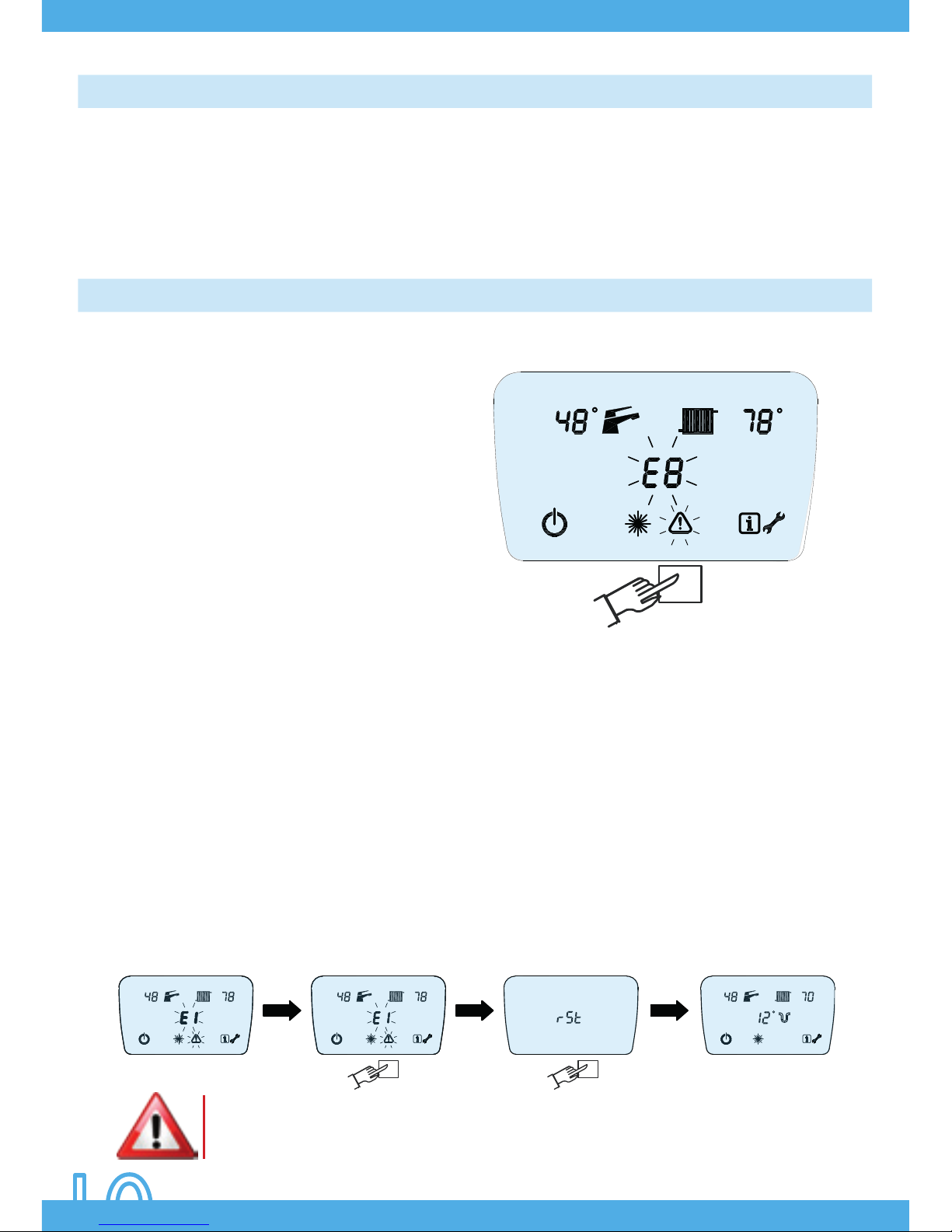
normal conditions as soon as possible. Fault
warnings are given on the LCD display. The
malfunction is detected and an intermittent
warning displayed immediately, consisting
of a number preceded by the error symbol E
(Pict. 10). Faults are displayed on any screen
of the main menu.
Conditions causing transitory faults are
possible. Many of these are recognized
and cause a temporary block which is
automatically reset once the condition
causing the fault has stopped. Some of these
provide for the possibility to attempt to restore
operation manually.
Manual error reset, recovery attempt
To manually reset the system following a
fault condition, press BUTTON 3: the symbol
RST (reset) will be displayed on the LCD
display. Then press BUTTON 3 again (Pict. 11).
The microprocessor will attempt to recover
the system by resetting all the conditions
presumed to have caused the fault. If the
operation is successful the boiler will return
to normal operation; if not, the error code
causing the malfunction will be displayed.
Pic. 11
Pic. 10
IF A FAULT IS NOT SOLVED AFTER 2 MANUAL RESET ATTEMPTS THEN THE AUTHORISED
TECHNICAL ASSISTANCE CENTRE MUST BE CALLED.
For optimum and even more economical
management of the domestic premises it is
possible to use the EASY CONTROL
programmable timer thermostat. EASY
CONTROL allows all main boiler functions to
be managed remotely,
allowing it to be fully managed from a
different room to that where the boiler is
installed.
EASY CONTROL can also be used to schedule
daily and weekly room temperatures and
manage reduced demand periods (holidays,
anti-frost and maintenance modes).
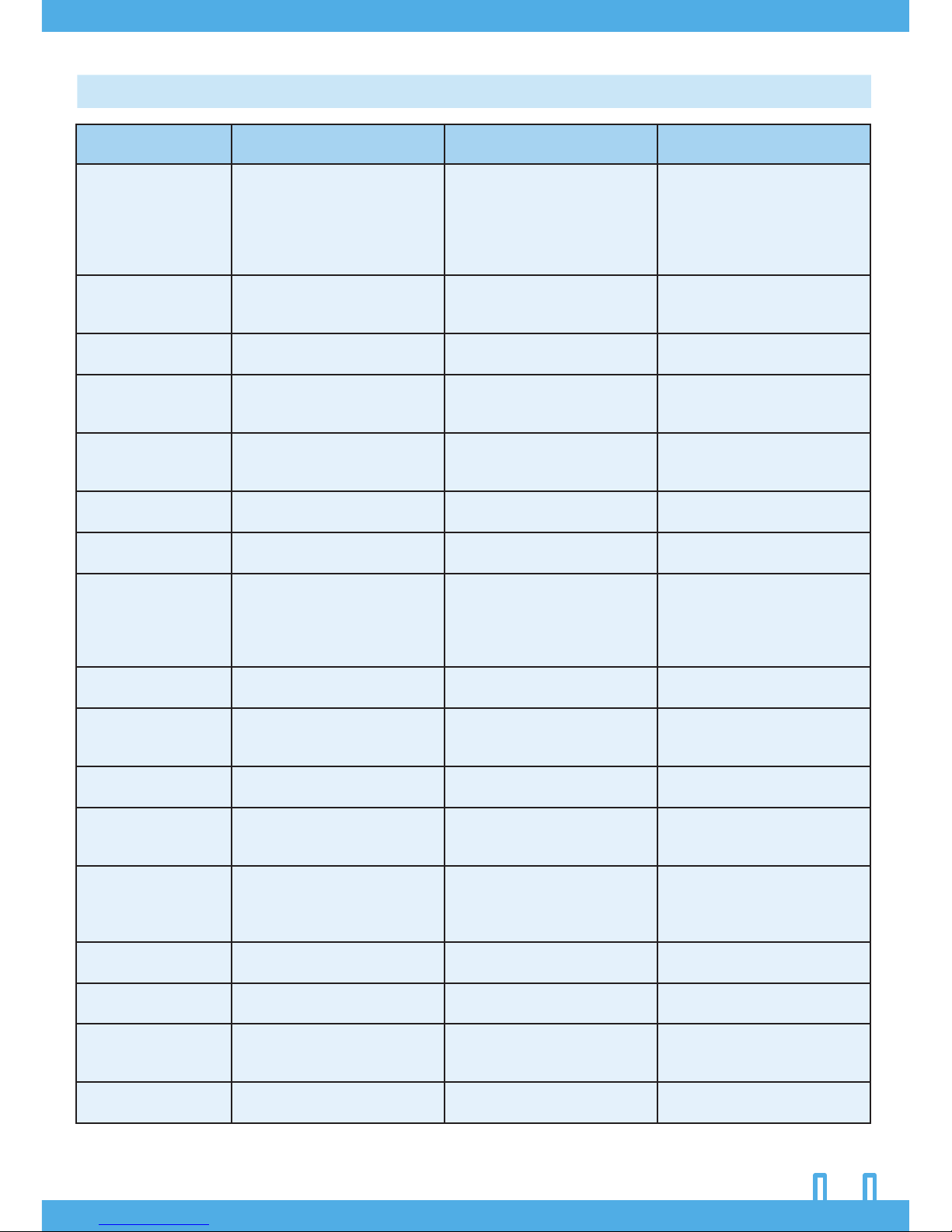
FAULT CODES TABLE (ALL MODELS)
Code Possible cause Behaviour Possible actions
E1 Ignition failed Boiler locked
Check gas presence
Check gas line pressure
Check ignition/detection
electrodes
Check electronic cable
Check igniter
E2 Air pressure switch failure Boiler locked
Check ue draught / ue
pipes
Check fan
E3
Heating system temperature
sensor fault
Boiler locked Replace CH sensor
E4
Domestic hot water system
temperature sensor fault
DHW supplied in provisional
mode
Heating functions normally
Replace CH sensor
E5 Gas regulation valve fault Boiler locked
Check wire connection to
modulator
Replace gas valve
E6
High temperature detected
by heating system sensor
Device in stand-by
Normal DHW supply
Wait for automatic unlocking
E8
Central heating system
pressure too low
Boiler locked Check pressure to CH system
E9
Central heating system
water temperature too high
Boiler locked
Degas CH system
Check CH system pressure
Check CH system circulation
Check combustion
adjustmen
E10
Central heating system
pressure too HIGH (> 2.7 bar)
Boiler locked Check pump functioning
E11 Pressure transmitter failure Boiler locked
Check integrity of
connection
Replace pressure trasmitter
E12
Remote control
reset used-up
Boiler locked
Reset system
Switch off power
E13 SYSTEM error Boiler locked
Reset system
Switch off power
Replace electronic board
E23*
Fault on external
temperature sensor
Resumption of operation
without external sensor
Check position of external
probe
Check communication line
Replace external sensor
E28
Water cylinder / water
heater probe failure
Boiler locked Replace probe
E70 Supply voltage too low Boiler locked
Controlling the supply of the
boiler
E77 System error Boiler locked
Reset system
Switch off power
Replace electronic board
E99
Parameter
conguration error
Boiler locked
Check and recongure the
parameters
*Can be displayed only if the relative devices are installed
GAS
INTAKE
DOMESTIC
HOT WATER
WATER
INTAKECHRETURN
1
2
CH FLOW
3
4
10
9
8
7
6
5
AB
B
A
1
2
3
BOILER
FLOW
BOILER
RETURN IN
HOT
WATER
OUTLET
COLD
WATER
INTAKE
Pic. 12
Pic. 13
Pic. 14
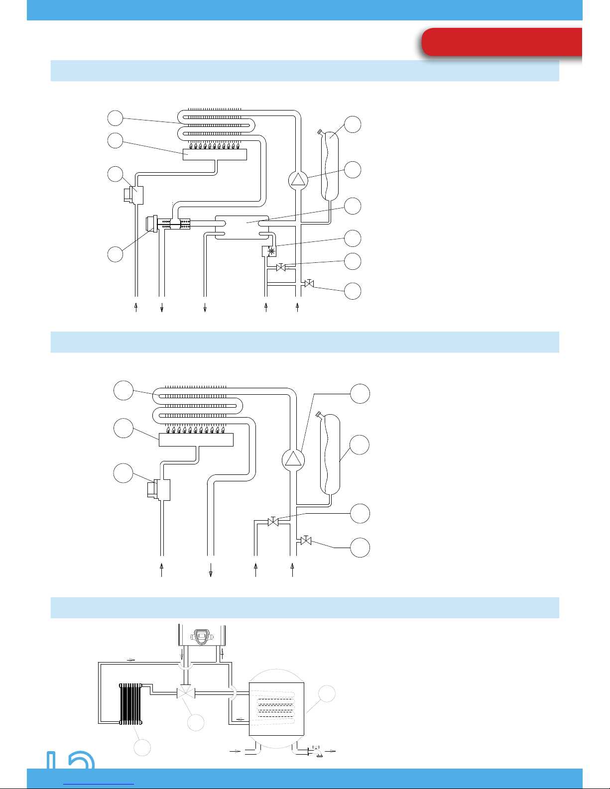
OPERATING DIAGRAM (MR)
OPERATING DIAGRAM (MN)
DHW STORAGE TANK- THREE WAY VALVE OPERATIONAL DIAGRAM
INSTALLATION
1) Primary heat exchanger
2) Burner
3) Gas valve
4) Three-way valve
5) Safety valve
6) Filling loop cock
7) Hot water priority turbine
8) Secondary heat exchanger
9) Circulator unit
10) Expansion tank
1) Primary heat exchanger
2) Burner
3) Gas valve
5) Safety valve
6) Filling loop cock
9) Circulator unit
10) Expansion tank
1) Central heating circuit
2) Three-way valve
3) DHW storage tank
COMBINATION: DOMESTIC HOT WATER + CENTRAL HEATING
CENTRAL HEATING ONLY
1
2
3
10
5
6
9
GAS
INTAKE
DOMESTIC
HOT WATER
WATER
INTAKECHRETURN
 Loading...