

Page 1

WIRELESS TRANSMITTER
WT2
ǵ
DEUTSCH
ENGLISH
FRANÇAIS
ITALIANO
PORTUGUÊS
Page 2
28
Package contents
1 WT2
2 WT2 installation kit (for attaching to television)
3 Mains cable for indoor TV installation (e.g. Lenaro)
4 Mains cable for external sockets (e.g. Vision Company)
5 Antenna module for indoor TV installation (e.g. Lenaro)
6 Antenna module for outdoor TV installation (e.g. Vision Company)
7 Antenna cable
8 2 Stereo cinch cables
9 I
2
C bus cables
10 Operating manual
11 Installation instructions for dealers
The wireless transmission system
WT2 communicates with
the audio transmission
receivers which are integrated in the FineArts
LSP2/LSP3 or RS Set 2
active loudspeakers. A
maximum of 4 active loudspeakers can be operated
through the wireless module. Due to the wireless
transmission, speaker
connection cables are no
longer necessary.
International and national
regulations limit the audio
transmission range to prevent radio interference. The
wireless audio transmission
power is ≤10 mW. This
guarantees an unhindered reception range of approximately 100 m. This
range is restricted inside buildings, depending on the construction
materials used.
Avoid placing the system near metal objects or electrical devices such as
cordless telephones which use radio signals.
Since the audio signals are not transmitted on an exclusive range, we cannot
guarantee that this will not cause interference. To avoid such interference,
16 different channel combinations are provided on the WT2 channel selection switch.
WIRELESS TRANSMITTER WT2
__________
ENGLISH
I
ǵ
Slider
Video in
Audio inLR
Volume Program
S-VHS
ǵ
Page 3
ENGLISH
29
Operation with individual Grundig components
Suitable devices for operation with the wireless module WT2 include the
Grundig televisions FineArts Vision, FineArts Planavision and others with I2C
connections (e.g. Lenaro). The WT2 can also be connected to a controlled
audio source.
In connection with your television, the WT2 controls the same LSP2/LSP3 or
RS Set 2 active loudspeakers as your Grundig HiFi system FineArts Audion.
You can operate these active loudspeakers variably through WT2 or through
FineArts Audion.
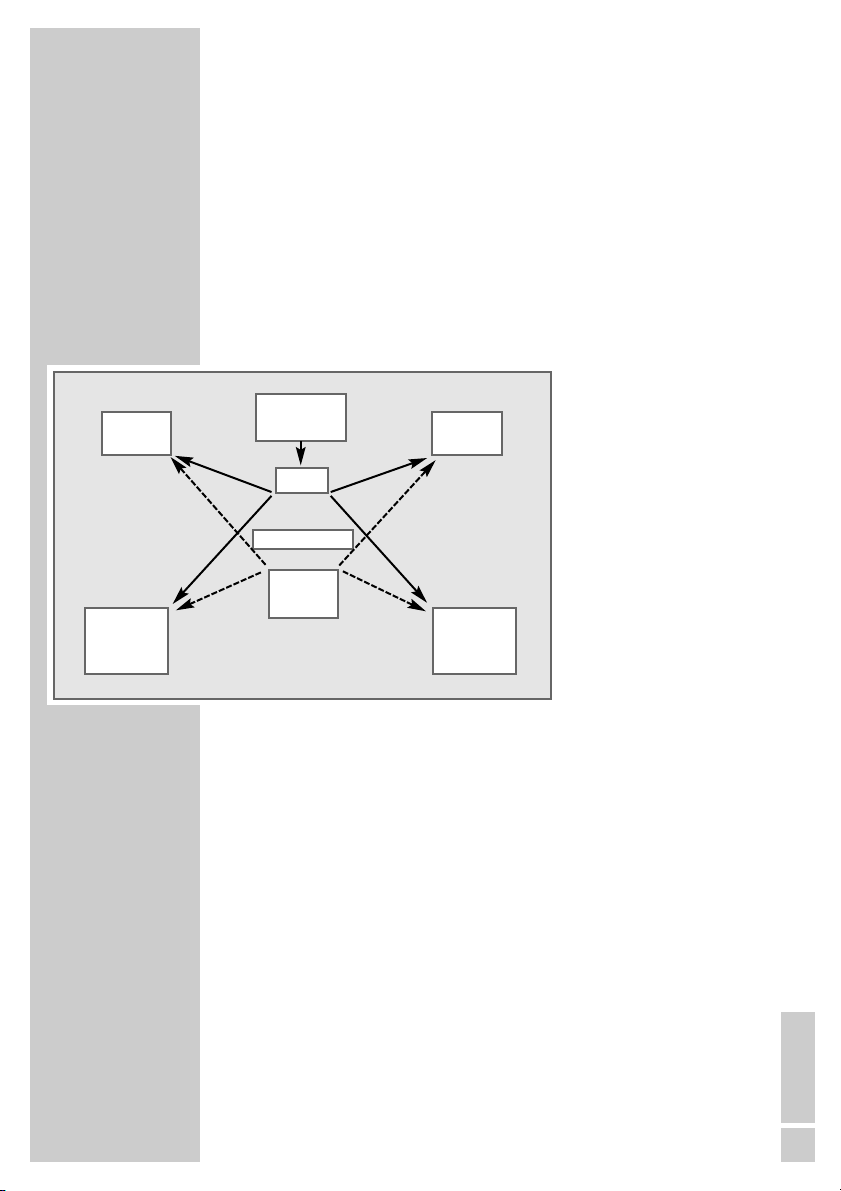
System configurations with television and FineArts Audion
Speaker configurations in television mode
You can operate one or up to four active loudspeakers with the WT2. When
using 4 LSP2/LSP3 or RS Set 2 active loudspeakers, each active loudspeaker can be defined for the WT2 – depending on the location of the television – as left/right and front/rear speaker.
These can be configured a number of ways depending on how many loudspeakers are used:
– two mono rear loudspeakers (Surround mode);
– two stereo rear loudspeakers (for Lenaro only);
– two stereo front loudspeakers;
– two stereo front loudspeakers, one mono rear loudspeaker;
– two stereo front loudspeakers, two mono rear loudspeakers (Dolby Pro
Logic mode with analog audio source);
– two stereo front loudspeakers, two stereo rear loudspeakers (Dolby Digital
mode with digital audio source - e.g. Lenaro).
OPERATING MODES
__________________________
LSP2
LSP3
RS Set 2
LSP2
LSP3
Seating position
LSP2
LSP3
RS Set 2
LSP2
LSP3
WT2
HiFi
system
Television
Page 4
30
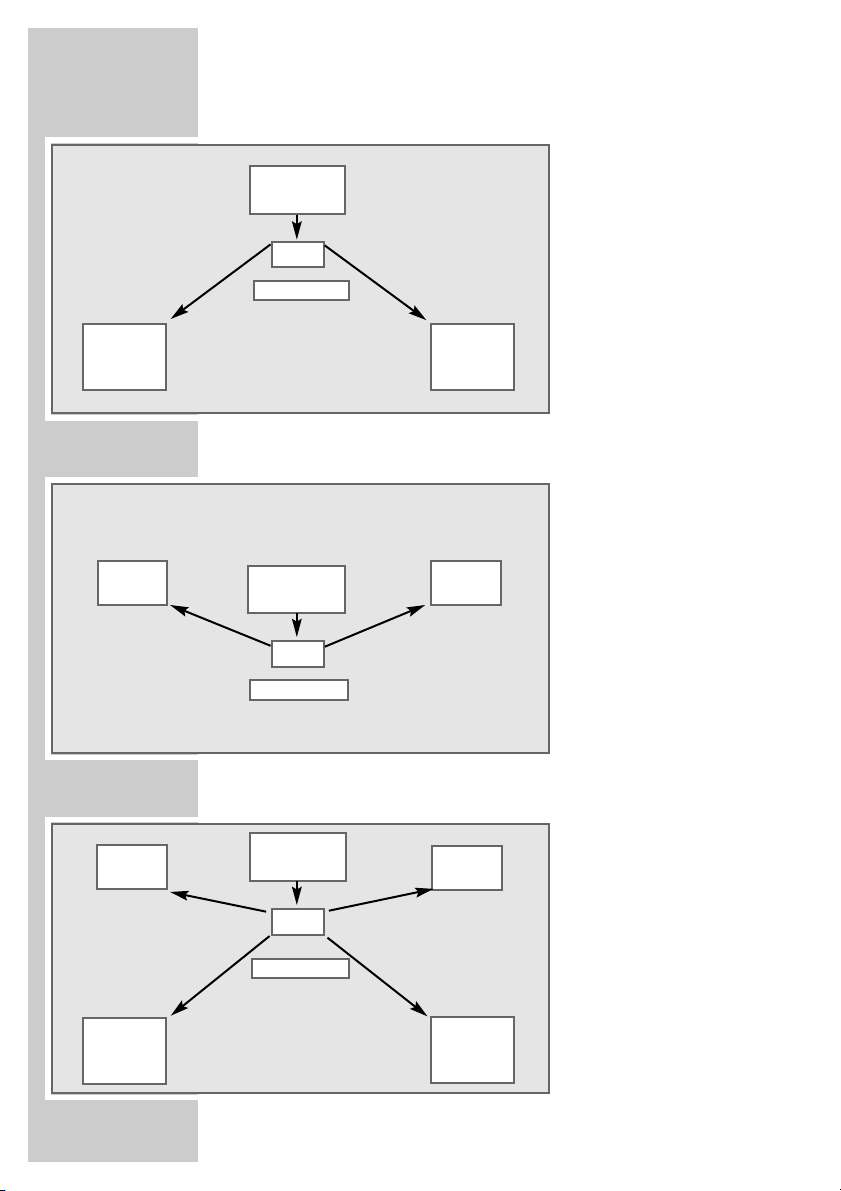
System configuration in Surround mode
System configuration in Stereo mode
Dolby Pro Logic or Dolby Digital mode
OPERATING MODES
___________________________
LSP2
LSP3
RS Set 2
LSP2
LSP3
RS Set 2
WT2
Television
LSP2
LSP3
RS Set 2
LSP2
LSP3
LSP2
LSP3
Seating position
Seating position
LSP2
LSP3
LSP2
LSP3
WT2
Television
Seating position
LSP2
LSP3
RS Set 2
WT2
Television
Page 5
ENGLISH
31
The assembly of the WT2 and the installation of the active loudspeakers are
to be performed by the dealer.
WT2 is designed for the sending of audio signals as well as the sending and
receiving of data signals. Any other use is expressly prohibited.
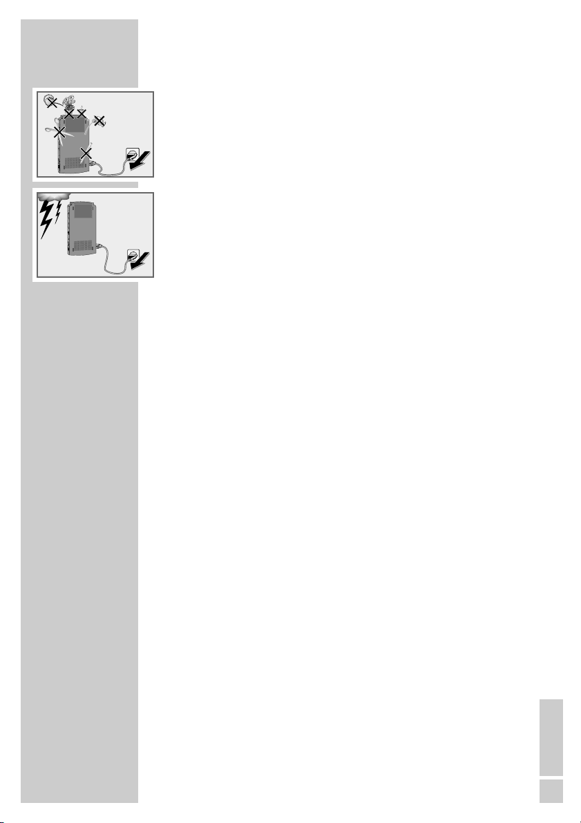
Do not place any vessels such as vases on the television or WT2. Should they
be knocked over, fluid may spill on the electrical components, thus presenting a safety risk.
Make sure no foreign bodies get inside the devices, as this may cause a short
circuit.
Ensure that the device is protected from moisture such as rain or water
splashes.
Thunderstorms are a danger to all electrical devices. Even if the WT2 is in
stand-by mode, it can be damaged by a lightening strike to the mains. In the
case of a thunderstorm, always first remove the mains plug from the active
loudspeakers and then from the WT2 (for FineArts Vision and Planavision)
or from the television (for Lenaro).
Do not open the WT2 under any circumstances. The manufacturer will not
accept any liability for damage resulting from improper handling.
SET-UP AND SAFETY
___________________________
! SERVICE !! SERVICE !
! SERVICE !
Page 6
32
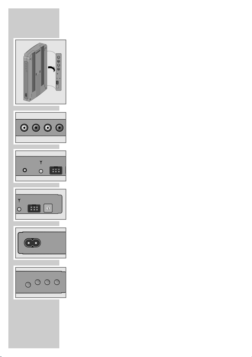
WT2 controls and connections
L STEREO R Stereo input jacks (left/right),
A Mono input jack (white); for connection
(using a cinch cable) to the television or an
audio source with controlled audio outputs.
L STEREO R Stereo input jacks (left/right),
B Mono input jack (white); for connection
(using a cinch cable) to the television or an
audio source with controlled audio outputs.
INSTALL Button:
for activating the loudspeaker installation
(FineArts Vision and Planavision);
for interrupting installation;
for registering with FineArts Audion;
for deleting all installation data (= original
state).
É Antenna jack for supplied antenna cable
(with FineArts Planavision, the antenna
cable is already built-in).
I
2
C Jack for I2C bus cable for data exchange
with a Grundig television with I2C connection (e.g. Lenaro).
SPEAKER INSTALL Channel selection switch:
CH-SELECT sets the number of the active loudspeakers
to be installed or the channel combination
(16 possible settings).
220-240 V~ 50/60 Hz Mains socket
Z
ǼǼ
LED (On/Stand-by).
Z
INSTALL LED. Indications for dealers.
Z
ERROR LED. Indications for dealers.
B Dual function – goes out after loudspeaker
pair B is successfully installed; flashes for
errors.
Z
MUTE LED. Indications for dealers.
A Dual function – goes out after loudspeaker
pair A is successfully installed; flashes for
mute function.
Information for dealers:
Further information, including that regarding software updates, can be
found in the installation instructions and the service documentation.
OVERVIEW
____________________________________________
A
C
LRSTEREO
B
A
BA
A
STEREO
CH-SELECT
4
5
6
3
2
7
1
8
0
9
F
A
E
B
D
C
220-240V
50/60 Hz
LRSTEREO
B
INSTALL
I
2
C
SPEAKER INSTALL
CH-SELECT
1
0
2
F
E
3
D
4
C
5
B
6
A
7
9
8
B
SPE
I2C
~
Ǽ
Ǽ
ERRORINSTALL MUTE
~
220-240V
50/60 Hz
LR
STEREOALR
INSTALL
SPEAKER INSTALL
I2C
ERRORINSTALL MUTE
Page 7
ENGLISH
33
CONNECTION (LSP)
___________________________
R
ESE
T
230V
50/60Hz
230V
50/60Hz
R
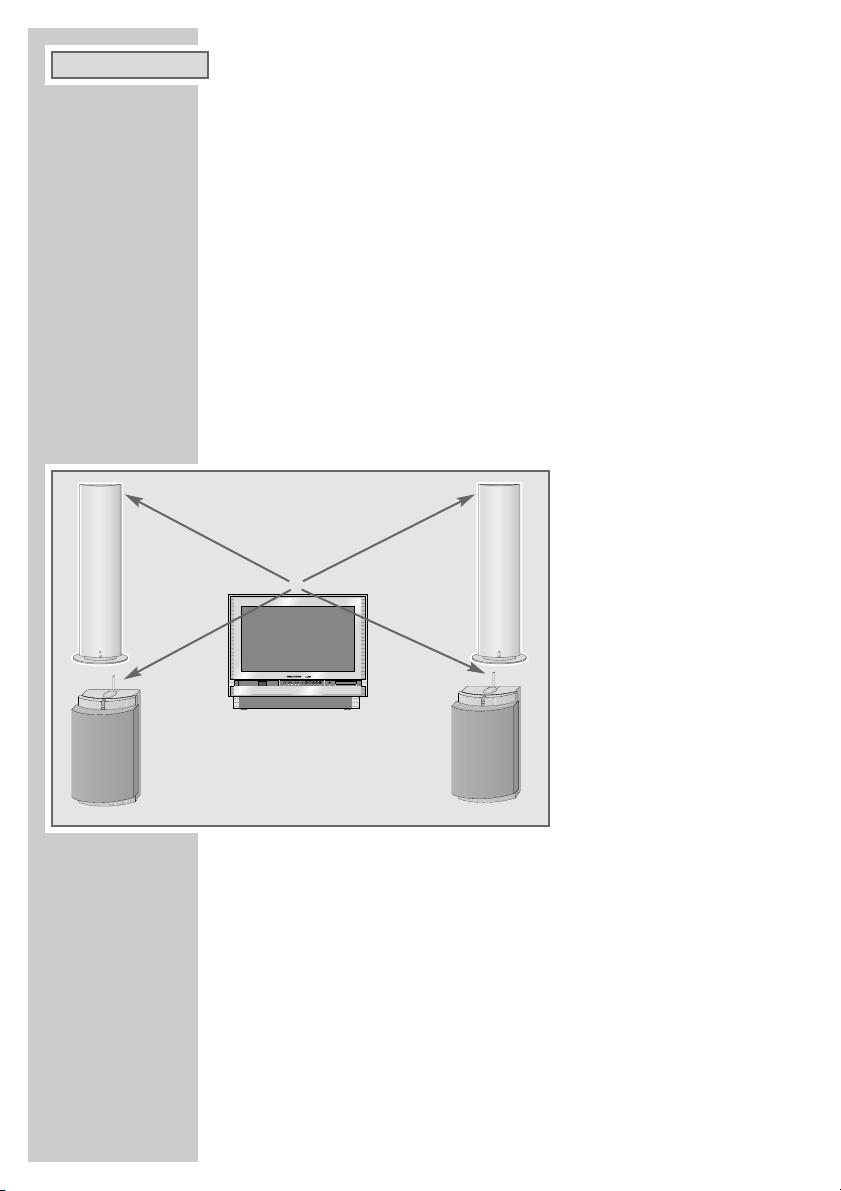
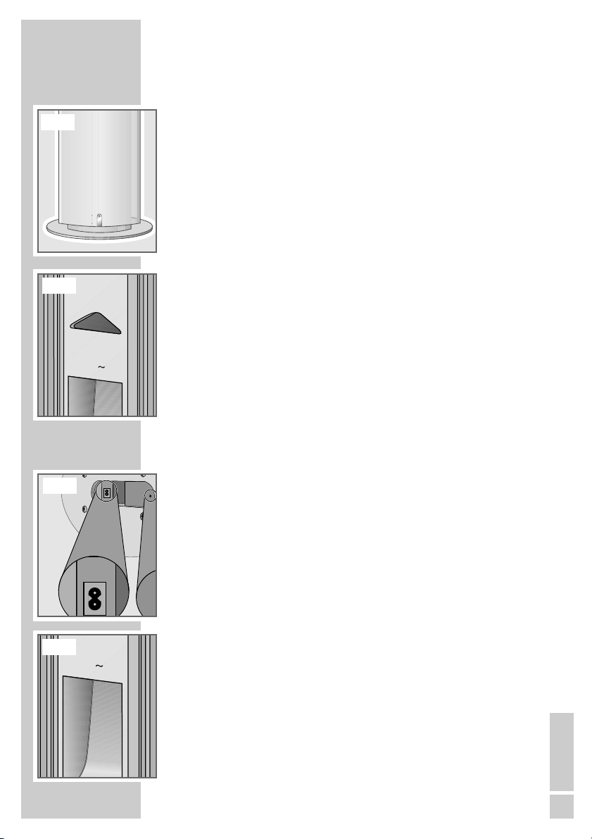
Positioning active loudspeakers
When used as stereo front loudspeakers, both LSP2/LSP3 active loudspeakers should always be positioned in the room next to the television in such a
way as to ensure unhindered transmission from the antenna module of the
WT2 transmitter. The same applies to using the LSP2/LSP3 or RS Set 2 active
loudspeakers as stereo rear loudspeakers or as mono rear loudspeakers.
LSP2 is a floor speaker with integrated antenna in the headpiece.
For the positioning of the LSP3 or RS Set 2 there are two options: wall-mounting or placing them on the floor, on furniture or shelves.
1 Place the LSP2 active loudspeakers in the room around the television;
– and/or
2 Hang the active loudspeakers (LSP3, RS-Set 2) by the recess on the back
of the speakers on a screw which has been firmly anchored in the wall.
Notes:
When setting up the active loudspeakers, make sure that the minimum
distance to the television is 1 m for LSP2 and 50 cm for LSP3. For the LSP3
and RS Set 2 active loudspeakers, the acoustics and the audio reception
requires a minimum positioning height of 0.8 m above the floor.
When setting up the active loudspeakers, make sure that they stand securely and are not affected by vibrations caused by resonance at high volumes. Feet are attached to the bottom of each active loudspeaker to increase stability.
Connecting active loudspeakers
1 Plug the supplied mains cable (1.5 m oder 4 m for LSP3 and RS Set 2) into
the jack »230 V~ 50/60 Hz« of the active loudspeaker.
2 Insert the mains cable plug in the socket.
Note:
See also the operating manual for the active loudspeakers.
LSP2
LSP2
LSP3
LSP3
MAINS
230V
50/60Hz
MAINS
230V
50/60Hz
Page 8
34
… for the Grundig televisions FineArts Vision (FAV)
and Planavision (FAP)
Note:
The mounting of the WT2 transmitter on the television and the installation
of the active loudspeakers may only be performed by authorised Grundig
dealers. See also the WT2 assembly instructions.
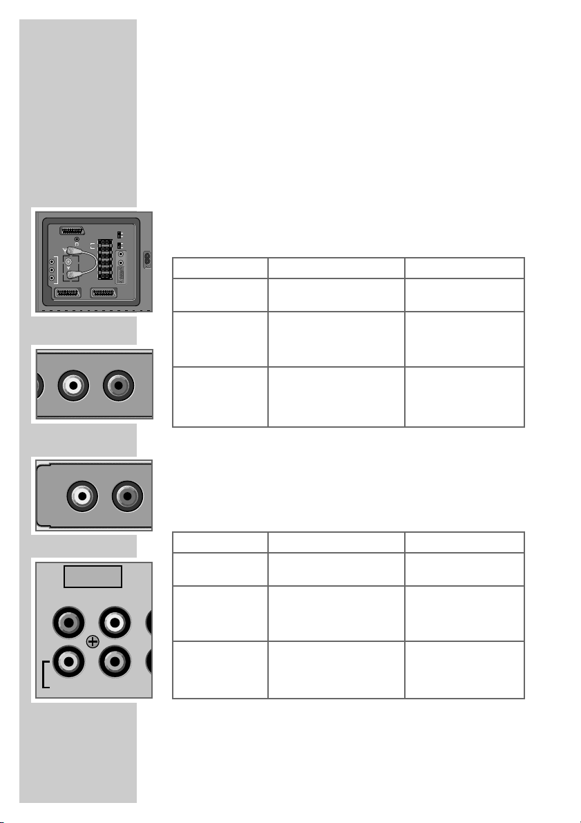
Connecting the WT2 to FineArts Vision
With the WT2, you may operate up to 4 wireless active loudspeakers with
your television. To do this, the following table shows how to connect WT2 to
the television using the supplied cinch cables.
Connecting the WT2 to FineArts Planavision
With the WT2, you may operate up to 4 wireless active loudspeakers with
your television. To do this, the following table shows how to connect WT2 to
the television using the supplied cinch cables.
CONNECTION (FAV/FAP)
__________________
Loudspeakers
Two mono rear
loudspeakers
Two stereo front
loudspeakers;
one mono rear
loudspeaker
Two stereo front
loudspeakers;
two mono rear
loudspeakers
FAV output jack
»SURR AUDIO OUT«
»L AUDIO R«
»SURR AUDIO OUT«
»L AUDIO R«
»SURR AUDIO OUT«
WT2 input jack
»L STEREO« (white)
B
»L STEREO R«
B
»L STEREO« (white)
A
»L STEREO R«
B
»L STEREO« (white)
A
Loudspeakers
Two mono rear
loudspeakers
Two stereo front
loudspeakers;
one mono rear
loudspeaker
Two stereo front
loudspeakers;
two mono rear
loudspeakers
FAP output jack
»DOLBY SURROUND«
»R DOLBY L«
»DOLBY SURROUND«
»R DOLBY L«
»DOLBY SURROUND«
WT2 input jack
»L STEREO« (white)
B
»L STEREO R«
B
»L STEREO« (white)
A
»L STEREO R«
B
»L STEREO« (white)
A
DOLBY
AU
SURROUND
R
L
LR
DVD
AV3
INT
CENTRE
EXT
CENTRE
INT
SUBW
EXTERN
EXT
SUBW
L
L
AUDIO IN
AUDIO
IN
SURR
L
OUT
AUDIO OUT
AUDIO
R
AV2 AV1
R LR
STEREO
R
R
SURR
VGA
B
LR
STEREO
A
Page 9

ENGLISH
35
Preparing FineArts Vision and Planavision televisions
The sockets on the television for use with the active loudspeakers must first be
activated. Various settings depend on the software version in the television.
Displaying the software version
1 Switch on the television and press »i« to open the »DIA-
LOGCENTER«. Press »OK« to confirm.
2 Select »AUX« to see the software version.
– The software version (29798-102.06 or 29798-
102.07) appears in the menu on the top left of the
screen.
Note:
Software version .06 contains the LF DPL component
29504-204.03, software version 07 contains the LF DPL
component 29504-204.13.
Settings for stereo front loudspeakers
Note:
Front loudspeakers for stereo and Dolby Pro Logic mode can only be
installed and the individual levels set on televisions with the 29798-
102.07 software.
If, when the TV software was updated from .06 to .07, the LF DPL component was not changed from .03 to .13, only mono rear loudspeakers
can be installed. If you want front loudspeaker operation (Stereo and
Dolby Pro Logic), the LF DPL component must be changed from .03 to .13
(see the WT2 assembly instructions with information on converting from
.03 to .13).
1 Press »
FF
« (blue) to open the »AUDIO SETTINGS«
menu. Press »OK« to confirm.
2 In the »AUDIO SETTINGS« menu, press »P+« or »P-« to
select the »Audio output« item.
3 Press »
Ǹ
« or »Ƿ« to select »Active box«, press »TXT«
to return to television mode and switch off the television.
4 Press »i« to open the »DIALOGCENTER« and press
»OK« to confirm.
5 In the »DIALOGCENTER«, press »P+« or »P-« to select
the »INSTALLATION« item and press »OK« to confirm.
6 In the »INSTALLATION« menu, press »P+« or »P-« to
select the »Speaker configuration« item and press
»OK« to confirm.
PREPARATION (FAV/FAP)
_________________
SOUND SETTINGS
Sound change ove P 1 Mono
HP-sound change Mono
Audio output Active box
Speaker output On
P+
P-
ļ
ļ
Ļ
Ļ
–
●
Ǻ
Return
●
?
Help
●
TXT
TV
•• •
To 1st page
F
29798-102.07 ǵ
REMOTE CONTROL
INDEX
PARENTAL LOCK
TV-PROGRAMME-CHART
AUTOMATIC PROGRAMMING
AUDIO-/VIDEO RE-RECORDING
P+
P-
ļ
Ļ
–
■
OK
Call up
●
?
Help
●
TXT
TV
A-Z
COPY
ATS
new
v
g
Page 10

36
7 In the »LS CONFIGURATION-SELECTION« menu, press
»P+« or »P-« to select the »SSubwoofer internal« item
and press »
Ǹ
« or »Ƿ« to select »no«.
Note:
The setting »no« means that the internal subwoofer
remains controlled, but at the same time, the bass
parts are also sent to the external front loudspeakers.
This configuration is required for a full acoustic pattern.
8 Press »TXT« to return to television mode and switch off
the television.
Settings for mono rear loudspeakers
Note:
Mono rear loudspeakers can be installed on televisions
with 29798-102.06 or 29798-102.07 software.
1 Switch on the television and press »
i« to open the »DIA-
LOGCENTER«. Press »OK« to confirm.
2 In the »DIALOGCENTER«, press »P+« or »P-« to
select the »INSTALLATION« item and press »OK« to
confirm.
3 In the »INSTALLATION« menu, press »P+« or »P-« to
select the »Speaker configuration« item and press
»OK« to confirm.
4 In the »LS CONFIGURATION-SELECTION« menu, press
»P+« or »P-« to select the »Surround speaker Passive«
item and press »
Ǹ
« or »Ƿ« to select »no«, and in the
»Active« item press »Ǹ« or »Ƿ« to select »yes«.
PREPARATION (FAV/FAP)
_____________________________
LS CONFIGURATION - SELECTION
Left/right speaker
internal yes
external no
Center speaker
internal yes
external no
Subwoofer
internal no
external no
Surround speaker
Passive no
Active yes
P+
P-
ļ
Ļ
–
■
OK
Connection picture
●
Ǻ
Return
●
?
Help
●
TXT
TV
AUX Standard setting
ļ
Ļ
••
H I F I
STEREO
LS CONFIGURATION - SELECTION
Left/right speaker
internal yes
external no
Center speaker
internal yes
external no
Subwoofer
internal yes
external no
Surround speaker
Passive no
Active yes
P+
P-
ļ
Ļ
–
■
OK
Connection picture
●
Ǻ
Return
●
?
Help
●
TXT
TV
AUX Standard setting
ļ
Ļ
••
H I F I
STEREO
INSTALLATION
Speaker configuration
Dolby level adjustment
Audio/video connections
VGA connection
Time and date
TV GUIDE configuration
P+
P-
ļ
Ļ
–
■
OK
Call up
●
Ǻ
Return
●
?
Help
●
TXT
TV
Page 11

ENGLISH
37
Note:
If stereo front loudspeakers are already installed, on
televisions with 29798-102.07 software the »Left/right
speaker Active box« item appears in the »LS CONFIGURATION-SELECTION« menu. This has no effect on
the settings for the mono rear loudspeakers.
5 Press »TXT« to return to television mode and switch off
the television.
Settings for stereo front and mono rear loudspeakers
Note:
Stereo front and mono rear loudspeakers can only be
installed on televisions with the 29798-102.07 software.
1 Enter the settings for the stereo front loudspeakers as
described on pages 35 and 36.
2 Enter the settings for the mono rear loudspeakers as
described in the previous section.
PREPARATION (FAV/FAP)
_____________________________
LS CONFIGURATION - SELECTION
Left/right speaker Active box
Center speaker
internal yes
external no
Subwoofer
internal yes
external no
Surround speaker
Passive no
Active yes
P+
P-
ļ
Ļ
–
■
OK
Connection picture
●
Ǻ
Return
●
?
Help
●
TXT
TV
AUX Standard setting
ļ
Ļ
••
H I F I
STEREO
Page 12

38
INSTALLATION (FAV/FAP)
_________________
Initial installation (FineArts Vision and Planavision)
If you only want to install two loudspeakers, please follow the instructions on
this page. If you want to install four loudspeakers, please read pages 39
and 40. WT2 may only be operated with the supplied mains cable (Euro
and right angle connectors). The WT2 may only be operated with the power
cable supplied (Euro and right angle connectors).
Initial installation of a pair of loudspeakers
If the WT2 is in its original state, the transmitter starts automatically in installation mode after connection to the mains (initial installation). The WT2 is
factory adjusted for two loudspeakers (»SPEAKER INSTALL CH-SEL-
ECT« in switch position 2). In the following example, you will therefore first
install a pair of loudspeakers (stereo front left/right or mono rear left/right).
Please note the different settings for the stereo front and mono rear loudspeakers (pages 35 and 36), and the installation sequence.
1 Make certain that all loudspeakers are switched off.
2 Turn on the television set and adjust to a low volume.
3 Connect WT2 plug »220-240 V~ 50/60 Hz« with the supplied mains
cable (Euro and right angle connectors) to the wall socket.
– The indicators »
ǼǼ
« and »A« illuminate red (»A« until installation is
complete), the indicator »INSTALL« flashes green.
4 Turn on the left loudspeaker with the mains switch.
– During the installation phase, the indicator »INSTALL« on the WT2
flashes green, the loudspeaker indicator flashes orange.
– After completion of installation, the indicator »INSTALL« on the WT2
flashes green/orange, the loudspeaker indicator flashes green.
Note:
If the loudspeaker indicator continuously illuminates orange when
switched on, it has already been installed at FineArts Audion. In this case,
briefly press »RESET« to put the loudspeaker in installation mode.
»RESET« should not be pressed for longer than 5 seconds, as this will
delete all installation data (= original state).
5 Turn on the right loudspeaker with the mains switch.
– During the installation phase, the indicator »INSTALL« on the WT2
flashes green/orange, the loudspeaker indicator flashes orange.
– After completion of installation, the indicator »INSTALL« on the WT2
extinguishes together with the indicator »A«, the indicators of both
loudspeakers continuously illuminate green. The television sound is
transmitted.
Note:
The installation can be prematurely interrupted by briefly pressing the
»INSTALL« button. In this case, the loudspeaker installations successfully
completed up until the interruption remain saved; on the WT2, all indicators extinguish except »
ǼǼ
«.
6 Replace the rear cover of the television only after the transmission
quality has been tested with WT2.
BA
LSP2
LSP3
220-240V
50/60 Hz
ERRORINSTALL MUTE
ǵ
~
Ǽ
Page 13

ENGLISH
39
Initial installation of two pairs of loudspeakers
If the WT2 is in its original state, the transmitter starts automatically in installation mode after connection to the mains (initial installation). In the following
example, you will therefore first install two pairs of loudspeakers (stereo front
left/right and mono rear left/right). Please carefully observe the installation
sequence. Please note the necessary pre-settings for the stereo front and
mono rear loudspeakers (pages 35 and 36), and the installation sequence.
1 Make certain that all loudspeakers are switched off.
2 Turn on the television set and adjust to a low volume.
3 Set the number of the four loudspeakers to be installed with
»SPEAKER INSTALL CH-SELECT« (switch setting 4).
4 Connect WT2 plug »220-240 V~ 50/60 Hz« with the supplied mains
cable (Euro and right angle connectors) to the wall socket.
– The indicators »
ǼǼ
«, »A« and »B« illuminate red (»B« until installation
of the first pair of loudspeakers is complete, »A« until installation of the
second pair of loudspeakers is complete), the indicator »INSTALL« flashes green.
Note:
If the settings are incorrect (switch settings 5,6 ... F,0), the installation cannot be started, the »INSTALL« indicator briefly flashes red. Correct the
switch setting and press the »INSTALL« button again.
5 Turn on the left front loudspeaker with the mains switch.
– During the installation phase, the indicator »INSTALL« on the WT2
flashes green, the loudspeaker indicator flashes orange.
– After completion of installation, the indicator »INSTALL« on the WT2
flashes green/orange, the loudspeaker indicator flashes green.
Note:
If the loudspeaker indicator continuously illuminates orange when
switched on, it has already been installed at FineArts Audion. In this case,
briefly press »RESET« to set the loudspeaker to installation mode.
»RESET« should not be pressed for longer than 5 seconds, as this will
delete all installation data (= original state).
6 Turn on the right front loudspeaker with the mains switch.
– During the installation phase, the indicator »INSTALL« on the WT2
flashes green/orange, the loudspeaker indicator flashes orange.
– After completion of installation, the indicator »INSTALL« on the WT2
flashes green. The indicator »B« on the WT2 extinguishes. The loudspeaker indicator flashes green.
7 Turn on the left rear loudspeaker with the mains switch.
– During the installation phase, the indicator »INSTALL« on the WT2
flashes green, the loudspeaker indicator flashes orange.
– After completion of installation, the indicator »INSTALL« on the WT2
flashes green/orange, the loudspeaker indicator flashes green.
INSTALLATION (FAV/FAP)
_____________________________
LSP2
LSP3
BA
SPEAKER INSTALL
I2C
ERRORINSTALL MUTE
CH-SELECT
4
5
6
3
2
7
1
8
0
9
F
A
E
B
D
C
ǵ
Ǽ
Page 14

40
8 Turn on the right rear loudspeaker with the mains switch.
– During the installation phase, the indicator »INSTALL« on the WT2
flashes green/orange, the loudspeaker indicator flashes orange.
– After completion of installation, the indicator »INSTALL« on the WT2
extinguishes together with the indicator »A«, the indicators of the four
loudspeakers continuously illuminate green. The television sound is
transmitted.
Note:
The installation can be prematurely interrupted by briefly pressing the
»INSTALL« button. In this case, the loudspeaker installations
successfully completed up until the interruption remain saved; on the WT2,
all indicators extinguish except »
ǼǼ
«.
9 Replace the rear cover of the television only after the transmission
quality has been tested with WT2.
Note:
WT2 may only be operated with the supplied mains cable (Euro and right
angle connectors).
Adjusting the Dolby volume
1 In the menu »INSTALLATION« use »P+« or »P-« to sel-
ect the line »Dolby level adjustment« and activate it with
»OK«.
– You will hear a hissing noise from the loudspeakers
(= test sound).
2 Adjust the loudspeakers with »
Ǹ
« or »Ƿ« so that they
are of equal respective volume.
Note:
The level can be changed in normal mode (TV, DVD).
3 Return to TV mode with »TXT«.
Registering WT2 with the HiFi system FineArts Audion
When you simultaneously operate WT2 with the HiFi system FineArts
Audion, you must register the wireless module with the HiFi system. This procedure is described in the installation instructions from FineArts Audion.
INSTALLATION (FAV/FAP)
_____________________________
LSP3
INSTALLATION
Speaker configuartion
Dolby level adjustment
Audio/video connections
VGA connection
Time and date
TV GUIDE configuration
P+
P-
ļ
Ļ
–
■
OK
Call up
●
Ǻ
Return
●
?
Help
●
TXT
TV
ǵ
Page 15

ENGLISH
41
... for Grundig televisions with I2C connection
(e.g. Lenaro)
Note:
Installation and connection of the WT2 may only be performed by an authorised Grundig dealer.
For televisions with I
2
C connection, the installation of the wireless transmission is carried out through menus on the television screen. If the appropriate software is not integrated in the television, the dealer must install an
update. For software status, see the WT2 installation instructions. The
»SPEAKER INSTALL CH-SELECT« switch is not required for televisions
with I2C connection.
For Lenaro models, active loudspeakers can only be installed in pairs.
Initial installation of loudspeaker pairs
If the television’s wireless module WT2 is in its original state, the installation
menu appears automatically when the television is switched on. In the following example you will install two loudspeaker pairs (front left/right and rear
left/right). However, this is only the case if an automatic transmission search
(ATS) has first been performed on the television.The loudspeakers must be
switched off prior to starting installation.
Please carefully observe the installation sequence, the television’s menu
directions show each next step to be performed. You can obtain information
at any time about the required steps by pressing »?« (Help).
1 Switch on the television.
– The menu »Loudsp. wireless module« appears.
2 Select the line »Install front« with »P+« or »P-«, activate
with »OK« and set to »Yes«; then confirm with »OK«
(if you do not intend to install front loudspeakers, press
»P+« or »P-« to select »No«).
3 Select the line »Install Surround« with »P+« or »
P-«,
activate with »OK« and set to »Yes«; then confirm with
»OK« (if you do not intend to install surround loudspeakers, press »P+« or »P-« to select »No«).
4 Select the line »Start installation« with »
P+« or »P-«
and confirm with »OK«.
– The status menu »Start installation« appears on the
television screen. It shows information on the current
installation status.
– The automatic installation procedure starts.
INSTALLATION (I2C)
____________________________
Page 16

42
5 Turn on the left front loudspeaker with the mains
switch.
– The loudspeaker indicator flashes orange,
after completion of the installation it flashes green.
Note:
If the loudspeaker indicator continuously illuminates
orange when switched on, it has already been installed
at FineArts Audion. In this case, briefly press »RESET«
to set the loudspeaker to installation mode.
»RESET« should not be pressed for longer than 5
seconds, as this will delete all installation data.
6 Turn on the right front loudspeaker with the mains
switch.
– The loudspeaker indicator initially flashes orange,
after completion of installation it flashes green.
7 Turn on the left rear loudspeaker with the mains switch.
– The loudspeaker indicator initially flashes orange,
after completion of installation it flashes green.
8 Turn on the right rear loudspeaker with the mains switch.
– The loudspeaker indicator initially flashes orange,
after completion of installation all four loudspeaker
indicators continually illuminate green. The television
sound is transmitted.
– The message »Installation completed« appears on the
television screen.
9 Press »
i« to quit the menu.
– Sound is not transmitted until the system configuration
has been set.
Note:
The installation can be prematurely interrupted by pressing »OK« on the remote control (»Installation abortted« appears). In this case, the loudspeaker installations
successfully completed up until the interruption remain
saved.
Registering WT2 with the HiFi system FineArts Audion
When you simultaneously operate WT2 with the HiFi system FineArts
Audion, you must register the wireless module with the HiFi system. This procedure is described in the installation instructions from FineArts Audion.
INSTALLATION (I2C)
_____________________________________
Page 17

ENGLISH
43
System configuration, e.g. for Lenaro
The system configuration, which is automatically set up during installation,
can be checked in the following ways:
1 Call up the television menu »EASY DIALOG« with »
i«.
2 Select the menu »Installation« with »P+« or »P-« and
activate with »OK«.
3 In the menu »Installation«, use »P+« or »P-« to select
the line »Loudspeaker configuration« and activate it
with »OK«.
Note:
In the menu »Speaker configuration« you can call up a
connection diagram with the yellow button.
INSTALLATION (I2C)
_____________________________________
Page 18

44
Adjusting the Dolby volume
For Dolby Digital mode, all loudspeakers must be set with equal volumes in
relation to each other. The Dolby level must be set only once after installation
and is retained for further operation thereafter.
1 Call up the menu »EASY DIALOG« with »
i«.
2 Select the menu »Installation« with »P+« or »P-« and
activate with »OK«.
3 On the second page, select the menu »Speaker configura-
tion« with »P+« or »P-« and activate with »OK«.
4 In the television menu »Speaker configuration«, use »P+«
or »P-« to select the line »Dolby level« and activate with
»OK«.
– You will hear a hissing noise from the installed loudspeak-
ers (= test tone).
5 In the television menu »Dolby level«, use »P+« or »P-« to
select the line »Volume« and set the desired value for the
entire system with »
Ǹ
« or »Ƿ«.
Note:
If you do not press »P+« or »P-«, the white bar moves
automatically from one line to the next.
6 Use »P+« or »P-« to select the line »F balance« and set the
balance between the front loudspeakers with »
Ǹ
« or »Ƿ«.
7 Press »P+« or »P-« to select »Center« and select »Ǹ«or
»Ƿ« to set the volume of the central loudspeaker.
8 Press »P+« or »P-« to select »Subwoofer« and select »Ǹ«
or »Ƿ« to set the volume of the subwoofer.
9 Use »P+« or »P-« to select the line »Rear« and set the volu-
me of the rear loudspeakers with »
Ǹ
« or »Ƿ«.
10 Use »P+« or »P-« to select the line »S balance« and set the
balance between the rear loudspeakers with »Ǹ« or »Ƿ«.
11 Press »
FF
« (blue) to return to the previous menu.
SETTINGS (I2C)
_____________________________________
Page 19

ENGLISH
45
Setting the Dolby processing times
The rear loudspeakers are usually placed nearer to the seating position than
the front loudspeakers. This is why Dolby Digital decoders are electronically
delayed by a fraction of a second. This serves to compensate for the different
processing times of the sound.
1 In the menu »Speaker configuration« use »P+« or »P-« to
select the line »Seating position« and confirm with »OK«.
2 Select your installation’s loudspeaker pair with »P+« or
»P-« and activate with »OK«.
3 Enter the four-digit distance from the seating position to the
loudspeakers with »0...9« and confirm with »OK«.
4 Quit the setting with »
i«.
Notes:
This completes the installation and WT2/TV configuration.
The loudspeakers automatically switch to stand-by when the
television is switched to stand-by or is switched off using the
power switch.
SETTINGS (I2C)
_________________________________
Page 20

46
OPERATION
__________________________________________
Switching the installed system on again
When switching on an installed system whose individual components have
been switched off at the power switch, proceed as follows:
1 Turn on the active loudspeakers with the mains switch.
– The indicators on the active loudspeakers light up orange (stand-by).
2 Switch on the television.
3 The active loudspeakers switch from stand-by to operational.
– The active loudspeaker indicators continuously illuminate green.
Operation with FineArts Vision or Planavision
Should the wireless transmission of the audio signal experience interference
during operation, use the switch »SPEAKER INSTALL CH-SELECT« to
select a different channel combination. The setting will be automatically
transferred to the active loudspeakers. The switching is normally accompanied by a slight delay in the audio transmission.
Note:
If, during operation, the active loudspeaker indicator flashes red, the unit
is overheated. Immediately turn off the active loudspeaker with the mains
switch (for LSP2 lower back side of unit) and let it cool down.
Operation for television units with I2C connection
(e.g. Lenaro)
If the audio signal experiences interference during radio operation, you
can open the »Loudsp. wireless module« menu, press »P+« or »P-« to select »Channel combination« and then press »Ǹ« or »Ƿ« to set a different
channel combination from 0 to 15. The switching is normally accompanied by a slight delay in the audio transmission.
Note:
If, during operation, the active loudspeaker indicator flashes red, the unit
is overheated. Immediately turn off the active loudspeaker with the mains
switch (for LSP2 lower back side of unit) and let it cool down.
Switching off
1 Switch the television to stand-by using the remote control.
Note:
Since no audio signal is sent, the active loudspeakers automatically
switch to stand-by either immediately or after 30 minutes, depending on
the television or audio source.
– The indicators in the active loudspeakers mains switch illuminate orange.
2 If the active loudspeakers are unused for long periods, turn them off with
the mains switch.
SPEAKER INSTALL
LSP2
LSP3
LSP2
I2C
CH-SELECT
4
5
6
3
2
7
1
8
0
9
F
A
E
B
D
C
ǵ
Page 21

ENGLISH
47
... for the Grundig televisions FineArts Vision (FAV)
and Planavision (FAP)
If you operate two stereo front loudspeakers over the WT2 for example, and
wish to then add two mono rear loudspeakers, a reinstallation must be performed. Please note the necessary pre-settings for the stereo front and mono
rear loudspeakers (pages 35 and 36), and the installation sequence.
Reinstallation of a loudspeaker pair
1 Connect additional cinch cables between WT2 and the television (see
page 34).
2 Set the number of the four loudspeakers to be installed with
»SPEAKER INSTALL CH-SELECT« (switch setting 4).
3 Turn on the television set and adjust to a low volume.
4 At the start of the installation, press the »INSTALL« button on the WT2
until the »INSTALL« indicator flashes green.
– After you release the button, the »
ǼǼ
«, »A« and »B« indicators light up
red. The »INSTALL« indicator continues to flash green.
Note:
With error settings (switch settings 5,6 ... F,0) the installation cannot be
started, the indicator »INSTALL« briefly flashes red. Correct the switch
setting and press the »INSTALL« button again.
5 Turn on the left front loudspeaker with the mains switch and set to instal-
lation mode by briefly pressing »RESET«.
– During the installation phase, the indicator »INSTALL« on the WT2
flashes green, the loudspeaker indicator flashes orange.
– After completion of installation, the indicator »INSTALL« on the WT2
flashes green/orange, the loudspeaker indicator flashes green.
6 Turn on the right front loudspeaker with the mains switch and set to instal-
lation mode by briefly pressing »RESET«.
– During the installation phase, the indicator »INSTALL« on the WT2
flashes green/orange, the loudspeaker indicator flashes orange.
– After completion of installation, the indicator »INSTALL« on the WT2
flashes green. The indicator »B« on the WT2 extinguishes. The loudspeaker indicator flashes green.
7 Turn on the left rear loudspeaker with the mains switch.
– During the installation phase, the indicator »INSTALL« on the WT2
flashes green, the loudspeaker indicator flashes orange.
– After completion of installation, the indicator »INSTALL« on the WT2
flashes green/orange, the loudspeaker indicator flashes green.
8 Turn on the right rear loudspeaker with the mains switch.
– During the installation phase, the indicator »INSTALL« on the WT2
flashes green/orange, the loudspeaker indicator flashes orange.
– After completion of installation, the indicator »INSTALL« on the WT2
extinguishes together with the indicator »A«, the indicators of the four
loudspeakers continuously illuminate green.
9 Set the Dolby level as described on page 40.
SYSTEM UPGRADE
______________________________
BA
A
C
R
ES
ET
230V
50/60Hz
RESET
LSP2
LSP3
SPEAKER INSTALL
I2C
ERRORINSTALL MUTE
INSTALL
CH-SELECT
4
5
6
3
2
7
1
8
0
9
F
A
E
B
D
C
RESET
Ǽ
SPE
I2C
Page 22

48
... for Grundig televisions with I2C connection
(e.g. Lenaro)
For televisions with I2C connection, the reinstallation of loudspeakers is carried out through the menus on the television screen. Installation data, if present, need not be deleted.
If you have only operated front loudspeakers previously, the following describes how to install an additional pair of rear loudspeakers. If you have
only operated rear loudspeakers previously, a similar procedure applies to
the installation of front loudspeakers.
Reinstallation of a loudspeaker pair
1 Switch off all loudspeakers that are to be re-installed.
2 Switch on the television.
3 Call up the menu »EASY DIALOG« with »i«.
4 Select the menu »Installation« with »P+« or »P-« and
activate with »OK«.
5 On the second page, select the menu »Speaker configu-
ration« with »P+« or »P-« and activate with »OK«.
6 Select the menu »Loudsp. wireless module« with «P+«
or »P-« and activate with »OK«.
7 Select the line »Install Surround« with »P+« or »
P-«,
activate with »OK« and set to »Yes«; then confirm with
»OK«.
8 Select the line »Start installation« with »P+« or »P-«
and confirm with »OK«.
– The status menu »Start installation« appears on the
television screen. It shows information on the current
installation status.
– The automatic installation procedure starts.
9 Turn on the left rear loudspeaker with the mains switch.
– The loudspeaker indicator initially flashes orange,
after completion of installation it flashes green.
SYSTEM UPGRADE
_____________________________
Page 23

ENGLISH
49
10 Turn on the right rear loudspeaker with the mains
switch.
– The loudspeaker indicator initially flashes orange,
after completion of installation the indicators of both
loudspeakers continually illuminate green. The television sound is transmitted.
– The message »Installation completed« appears on
the television screen.
11 Press »
i« to quit the menu.
Note:
You can break off the installation by pressing »OK« on
the remote control (the message »Installation aborted«
appears).
12 Set the Dolby level and Dolby processing times as
described on pages 44 to 45.
Resetting the WT2 to its original state
Note for dealers:
With this function you can delete all existing installation data and reset the
WT2 to its original state.
1 When switched on, press »INSTALL« for longer than 10 seconds using
an implement such as a thin pen.
– The indicator »INSTALL« flashes green/red.
Note:
After the installation data has been deleted, the loudspeakers must be
reinstalled on the WT2.
Reset mode is not required during operation and installation, and is
therefore only available to service specialists.
SYSTEM UPGRADE
_____________________________
Page 24

50
Rectifying minor problems
In some circumstances, people, walls and other surfaces can reflect radio
signals. This can lead to noise or a temporary loss of sound. When such a
problem occurs, it usually suffices to reposition the loudspeaker or select a
different channel combination on the WT2.
If the remedies below are not successful, please consult an authorised
Grundig dealer.
INFORMATION
_____________________________________
Fault
The active loudspeakers do not work.
The active loudspeaker LEDs flash red.
There is noise interference on the active
loudspeakers.
Possible cause
The active loudspeakers have
not been installed.
The active loudspeakers have
not been switched on.
In the menu Loudspeaker configuration/Front left/right
and/or Surround, the menu
item »Connection« has not been
set to »Wireless« (Lenaro only).
The wireless module WT2
antenna is not directed at the
active loudspeakers (FAV and
FAP only).
The wireless module WT 2 is not
or incompletely connected to
the television.
The active loudspeaker is overheated.
Interference from a foreign
device, e.g. wireless headphones, remote controls, etc.
Remedy
Install the active loudspeakers.
Check the power cable and
switch on the active loudspeakers.
Make the appropriate settings.
Change the position of the
active loudspeakers until
they switch on from standby (FAV and FAP only).
Connect the input jacks of
the wireless module WT 2
and the television’s
stereo output jacks (for
stereo transmission) or the
input jacks of the wireless
module WT2 and the television’s surround output
jacks (for mono transmission) using a cinch cable
(FAV and FAP only).
Turn off the active loudspeaker with the mains
switch and let it cool down.
Select another channel
combination on the WT 2
(FAV and FAP only) or
through the television menu
»Loudspeaker wireless
module« (I
2
C only).
Page 25

ENGLISH
51
Fault
You install two active
loudspeakers; one
loudspeaker is not
registered by the
WT2.
You install four active
loudspeakers; one or
more loudspeakers
are not registered by
the WT2.
No audio playback
although loudspeakers are already
installed.
The »ERROR« LED
flashes on the WT2.
Possible cause
Data signal transmission interference.
Data signal transmission interference.
Data communication is blocked.
Communication fault.
Remedy
Reset the WT2 and the
active loudspeakers to their
original state (for setting
the WTS see page 49, for
the active loudspeakers see
the corresponding operating instructions) and repeat
the initial installation.
Reset the WT2 and the
active loudspeakers to their
original state (for setting
the WTS see page 49, for
the active loudspeakers see
the corresponding operating instructions) and repeat
the initial installation.
FAV and FAP only: switch
off the loudspeakers.
Disconnect the power cord
from the WT2 and plug it
in again after a short time.
Switch on the loudspeakers. I
2
C only: using the
power switch, switch off the
television and switch it on
again shortly afterwards.
FAV and FAP only: switch
off the loudspeakers.
Disconnect the power cord
from the WT2 and plug it
in again after a short time.
Switch on the loudspeakers. I
2
C only: using the
power switch, switch off the
television and switch it on
again shortly afterwards.
INFORMATION
___________________________________________
Page 26

52
INFORMATION
___________________________________________
Additional information for units sold in the UK.
Units sold in the UK are suitable for operation from a 240V ac, 50Hz mains
supply.
The range of multi-system receivers is built to work in most European countries. However, the mains plug and socket system for the UK differs from
many European countries.
This appliance has been supplied with a fitted, non-removable, approved
converter plug for use in the UK. This converter plug is fitted with a 5A rated
fuse.
In case this appliance is supplied with a moulded 2-pin Euro plug only,
which is unsuitable for UK operation, this must be cut off and immediately
disposed of. An approved 13A, 3-pin UK plug should then be fitted by a
qualified electrician.
Note:
The severed Euro plug must be destroyed to avoid a possible shock
hazard should it be inserted into a socket elsewhere.
If a non-rewireable 3-pin plug or a rewireable 13A (BS1363) 3-pin plug is
used, it must be fitted with a 5A ASTA or BSI approved BS1362 fuse. If any
other type of plug is used it must be protected by a 5A fuse either in the
plug, or at the distribution board. If this type of plug becomes defective,
ensure that the fuse is removed before disposal, to eliminate potential shock
hazard.
If it is necessary to change the fuse in the non-rewireable plug, the correct
type and rating (5A ASTA or BSI approved BS1362) must be used and the
fuse cover must be refitted. If the fuse cover is lost or damaged, the lead and
plug must not be used until a replacement is obtained. Replacement fuse
covers should be obtained from your dealer.
Important:
The wires in the mains lead are colour coded in accordance with the following code:
BLUE – NEUTRAL
BROWN – LIVE
As the colours of the wires in the mains lead of your appliance may not correspond with the coloured marking identifying terminals in your plug, proceed as follows:
Connect the BLUE coloured wire to plug terminal marked with the letter “N”
or coloured black.
Connect the BROWN coloured wire to the plug terminal marked with the letter “L” or coloured red.
In no circumstance must any of the wires be connected to the terminal marked with the letter “E”, earth symbol “
z”, coloured green, or green & yel-
low.
Replacement mains lead sets can be obtained from your local dealer, or by
contacting Grundig Consumer Relations (01788 570088)
Moulded 3-pin lead set, suitable for UK use:
Ref: Leadset UK 8290-991-224
Moulded 2-pin Euro lead set, not suitable for UK use:
Ref: Leadset Euro 8290-991-316
Page 27

ENGLISH
53
The wireless WT2 is noise-suppressed according to the applicable EU directives. These products fulfil the European directives 89/336/EEC,
73/23/EEC and 93/68/EEC.
This device conforms to the safety regulation DIN EN 60065
(VDE 0860) and therefore the international safety regulation IEC 60065.
The type plate with information on the operating voltage and radio certification is located on the bottom of the device.
Technical data
Current supply: 220-240 V~ 50/60 Hz
Power consumption during operation: 5.5 W
Power consumption in stand-by mode: 1.6 W
Transmission power: 10 mW
Transmission frequency
Wireless audio: 863 MHz – 865 MHz
Transmission frequency
Data signals: 869.7 – 870.0 MHz
Channels: 40 channels, channel intervals 50 kHz
Dimensions (W x H x D): 116 mm x 219 mm x 41 mm
Weight: 0.49 kg
Technical and optical modifications reserved.
INFORMATION
___________________________________________
DFM 869
AFM 864
Page 28

Grundig AG • Beuthener Str. 41 • D-90471 Nürnberg • http://www.grundig.com 28017 942 2000
 Loading...