

Page 1

COLOR TELEVISION
ǵ
ENGLISH
29120-269.0200
WIRELESS SOUND TRANSMITTER
WST 864
Page 2

2
CONTENTS
__________________________________________________________________________
3 Scope of delivery
4 Safety
5 The Wireless Sound Transmitter
6 Setting-up
Setting up in shelf unit
Mounting on the wall
9 Connecting and setting
Connecting transmitter
Setting transmission channel
10 Starting
Switching on and operation
Notes on operation and possible interference
11 Information
Technical data
Rectifying malfunctions
Page 3

ENGLISH
3
SCOPE OF DELIVERY
___________________________________________________
1 One TU 864 transmitter unit
2 Two RU 864 receiver units, installed
3 Two rear panels with connecting cable (3 m) for wall mounting
4 Operating instructions
5 Two installation angles
6 One cinch cable
7 One 14 Volt plug power supply
14V
SURROUND
7531
•••••••
ǵ
COLOR TELEVISION
WIRELESS SOUND TRANSMITTER
WST 864
1
3
675
2
4
Page 4
4
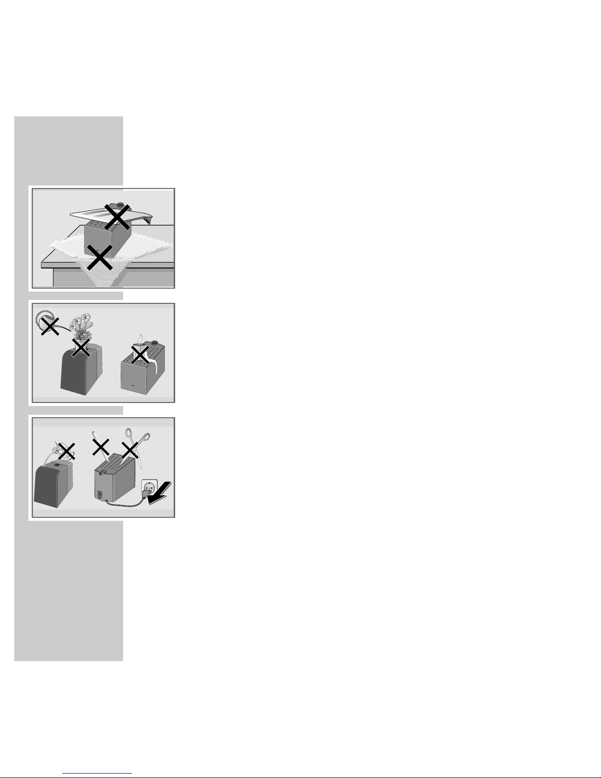
SAFETY
___________________________________________________________________________________
To ensure that this high-quality and user-friendly WIRELESS SOUND
TRANSMITTER gives you lasting satisfaction and enjoyment, it is very important
that the following points are observed when setting up the appliances.
The sound system is designed for transmitting and receiving sound signals.
Any other use is explicitly forbidden.
Do not cover the ventilation openings on the receivers.
Do not damage the mains cables.
Make sure that fluids or objects do not come into contact with the inside of the
appliances (danger of short circuiting).
Only suitably qualified personnel are authorized to open and service the appliances.
If the appliances are not used over a longer period of time (e.g. vacation), then
the mains plugs should be pulled out of the sockets.
When cleaning the appliances, use only a soft, damp cloth. Use only clean
water.
The type plate is attached to the base of the receivers.
! SERVICE !! SERVICE !
! SERVICE !
Krieg am Golf
Page 5

ENGLISH
5
THE WIRELESS SOUND TRANSMITTER
________
The WIRELESS SOUND TRANSMITTER system allows the transmission of sound
signals from your TV set to the Surround speakers without use of a wire.
The transmission range is approx. 20 meters. The system is designed for use in
a room.
The following illustration shows the connection diagram for the system.
Note:
Use your Grundig TV set speakers (e.g. with Arganto DPL) for the black-colored WIRELESS SOUND TRANSMITTER system.
If you have purchased the “polar-colored” WIRELESS SOUND TRANSMITTER system, you can order the matching speakers at your authorized
dealer (RS Set 1, ordering no. GAE 4942).
14V
SURROUND
7531
•••••••
To the »SURROUND«
socket on the TV set
Page 6

6
SETTING-UP OPTIONS
______________________________________________
The TU 864 transmitter is placed next to your TV set;
you have 3 options for setting up the RU 864 receivers and the swiveling
Surround speakers:
1 Receiver and speaker can be set up on a shelf, for example.
2 The speakers can be mounted on the wall.
3 The speakers can be mounted in an upright position using a stand mounted
on a floor plate.
3 (Accessories, base, RS-STAND 1, black: order no. GAE 5375, polar: order
no. GAE 5300).
Note:
Please provide sufficient protection for the surfaces of your furniture, the
receivers, and the speakers so that they will not be damaged during the
mounting.
Page 7

ENGLISH
7
SETTING UP
________________________________________________________________________
Installation on a shelf
1 Fasten speaker to the rear panel by pressing button on speaker and pushing
both parts together.
Wall mounting
1 Fasten the installation angle to the wall
Note:
You can stabilise the position of the angle with 2 pins.
2 Fasten the supplied rear panel with connecting cable (3m) to the speaker by
pressing the button on the speaker and pushing both parts together.
Page 8

8
SETTING UP
________________________________________________________________________________
3 Insert the speaker cable through the rear hole of the mounting angle. Screw
the speaker to the installation angle with the supplied screw.
4 Lay speaker cable.
5 Remove cover from receiver unit. To do so, press latch on the top left of the
cover, fold cover to the front and them pull away upwards.
6 Press down terminal lever, pull off speaker cable and take off rear speaker
panel.
7 Put up receiver unit and connect speaker cable to terminals of the receiver
unit.
Press down the terminal levers to insert the speaker cable.
– Insert the speaker »–« wire into the black (–) terminal, the speaker cable
»+« wire (marked or coloured wire) into the red terminal.
8 Place bottom part of cover into bottom part of receiver unit and push down
at the top until it snaps on.
– Pay attention to location of cable.
9 Insert mains plug into socket.
3.
2.
1.
Page 9

ENGLISH
9
CONNECTING AND SETTING
______________________________
Connecting transmitter
1 Connect the »SURROUND« cinch socket on the TV set with the
»SURROUND« cinch sockets on the transmitter using the cinch cable
provided.
2 Insert the plug power supply socket into the »14V« socket.
3 Insert plug power supply into the mains socket.
Note:
The transmitter should be set up near to the TV set in such a way that a clear
signal path is not blocked by any obstacle between itself and the speakers
and receivers.
Setting transmission channel
The slide switch on the transmitter and
on both receivers is for setting the transmission channel.
7 channels can be selected.
1 Select the same channel using the »CHANNEL« slide switch on the transmit-
ter and on both receivers.
Note:
If the transmission has radio interference (e.g. from another appliance which
is transmitting on the same frequency), please select another transmission
channel for the transmitter and both receivers.
14V
SURROUND
7531
•••••••
To the
»SURROUND«
socket on the TV set
CHANNEL 1 3 5 7
ǵ
RU 864
230V~ 50/60Hz
NF-VERSTÄRKER
POWER AMPLIFIER
MADE FOR GRUNDIG IN THAILAND
e j n
Page 10

10
STARTING
_____________________________________________________________________________
Switching on and operation
1 Switch on both receivers by using the »POWER« switch.
– The displays illuminate red.
2 Switch on your television set.
3 Activate the »Dolby Surround Prologic« (see the operating manual for your
TV set) function in the sound menu for your television set.
Notes:
The transmitter will be automatically switched on if the TV programme or the
AUDIO/VIDEO playback is transmitted with Dolby Surround Prologic.
– The transmitter display illuminates green.
The sound signal of the TV set is transmitted to the receivers via the transmitter without use of a wire and the receivers are ready for operation.
– The receiver displays illuminate green.
If a sound signal is not transmitted, the transmitter and both receivers will
switch off automatically (approx. 1-2 minutes).
– The display illuminates red.
Notes on operation and possible interference
Your WIRELESS SOUND TRANSMITTER is equipped with an HF system which
enables the transmission and reception of audio signals without additional
cable. International and national regulations limit the HF transmission power to
avert radio interference signals which could, for example, come from your
neighbors. The HF output is 10 mW. This guarantees a receiving distance of
approx. 30 m in free space. If the distance to the transmitter is greater, the signal is too weak to be received.
Under certain circumstances, persons, walls or other surfaces can reflect the
radio signals. Reflected signals mixed with direct (non-reflected) signals can
cause signal disturbance, called multipath reception. This can lead to audio
distortion or a short period of loss of sound. If this type of signal disturbance arises, positioning the transmitter in a different location will be sufficient to
rectify the problem.
ON
OFF
Page 11

ENGLISH
11
INFORMATION
________________________________________________________________
Technical data
Transmitter
Voltage supply: 10.5 V – 16 VPower requirement: 2.2 W
Transmitter frequency: 864 MHz/7 channels
Dimensions (W x H x D): 127 mm x 52 mm x 135 mm
Receiver
Voltage supply 230 V~, 50/60 Hz
Power requirement: 50W; in standby 1.3 W
Output: 2 x 25 W, (2 x 15 W sine)
Reception frequency: 864 MHz/7 channels
Dimensions (W x H x D): 80 mm x 89 mm x 144 mm
These appliances are noise-suppressed in accordance with the current EC guidelines. These appliances comply with the VDE (Association of German Electrical Engineers) 0860/BS 415 regulations and the EN 60065 safety regulations.
The appliances meet the 89/336/EEC, 73/23/EEC and 93/68/EEC European
guidelines.
Page 12

12
INFORMATION
__________________________________________________________________________
Rectifying malfunctions
If the remedial measures listed below do not lead to a satisfactory result, please
consult a GRUNDIG authorized dealer.
Fault Possible cause Remedial measures
The Surround speakers
Both receivers and the transmitter Change the position
have ceased to function.
are not in alignment. of both receivers or the
transmitter until the receivers
switch on from standby.
(A prerequisite for this is that
a Dolby Surround Prologic
programme is playing.)
This TV set is not set to Set to Dolby-Surround-ProLogic
Dolby-Surround-ProLogic mode. mode in the TV sound menu.
Both receivers or the transmitter Connect the appliances to
are not connected to the mains the mains supply.
supply.
The receivers are not switched on. Press the »POWER« button
on the receivers.
The channels are not Position the slide switch onto
correctly tuned in with one another. the same transmission channel.
The transmitter is not connected Connect the »SURROUND«
to the TV set. sockets for the transmitter to
the TV set using a cinch cable.
The playback of the Radio interference caused by Select another transmission
Surround speakers another appliance. channel for the transmitter
has interference. and both receiver units.
Grundig AG • Kurgartenstraße 37 • D-90762 Fürth • http://www.grundig.de
 Loading...