

Page 1
TV Service Manual
1. Ergänzung / Supplement 1
Chassis D5
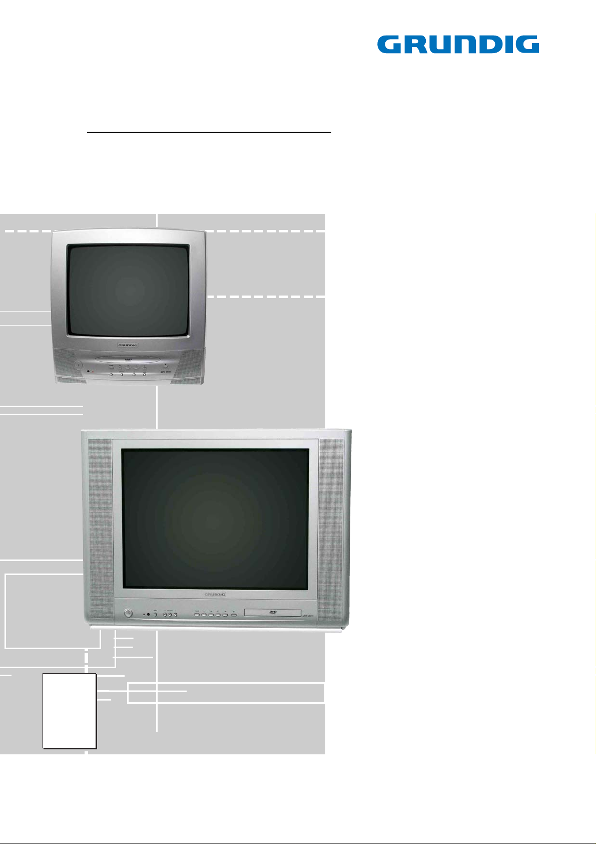
DVD Combo TV
Davio 14
TVD 37-2401 Text
GBC3200
Elegance 21 Flat
TVD 55-2401/5 Top
GBC3300
Zusätzlich erforderliche Unterlagen für den Komplettservice
Additionally required Service Documents for the Complete Service
Service
Manual
Sicherheit
Safety
Materialnr./Part No.
720108000001
Materialnummer/Part Number 720100488000
Änderungen vorbehalten/Subject to alteration • Printed in Germany …
H-S43 0105 • 8002/8012 oUKIRL, 8003/8013 oD, 8005/8015
http://www.grundig.com
Page 2

GRUNDIG Service Chassis D5
Es gelten die Vorschriften und Sicherheitshinweise
gemäß dem Service Manual "Sicherheit", Materialnummer 720108000001, sowie zusätzlich die eventuell abweichenden, landesspezifischen Vorschriften!
Inhaltsverzeichnis
Seite
Allgemeiner Teil ................................. 1-2…1-14
Allgemeine Hinweise.................................................................... 1-2
Technische Daten ........................................................................ 1-3
Bedienhinweise ............................................................................ 1-5
Service- und Sonderfunktionen.................................................. 1-10
Sicherheits-Hinweis ................................................................... 1-11
IC Data Sheet & Specification (englisch) ................................... 1-12
Abgleich .........................................................2-1
Platinenabbildungen
und Schaltpläne ................................. 3-1…3-18
Block Diagram.............................................................................. 3-1
ZL6.190-03:
– Netzteil ..................................................................................... 3-2
– Ablenkung ................................................................................ 3-3
– NF-Endstufe ............................................................................. 3-4
– Leiterplatte ............................................................................... 3-5
ZL5.190-03
– Signalverarbeitung ................................................................... 3-6
– Leiterplatte ............................................................................... 3-9
ZL5.194 Bildrohrplatte................................................................ 3-13
ZL6.194 Bildrohrplatte................................................................ 3-14
ZL5.192-01 AV-Platte ................................................................ 3-15
ZL6.192-02 AV-Platte ................................................................ 3-16
ZL5.191 Bedienplatte................................................................. 3-17
ZL5.195 Bedienplatte................................................................. 3-17
ZL6.191 Bedienplatte................................................................. 3-18
The regulations and safety instructions shall be valid
as provided by the "Safety" Service Manual, part
number 720108000001, as well as the respective
national deviations.
Table of Contents
Page
General Section.................................. 1-2…1-14
General Notes .............................................................................. 1-2
Technical Data ............................................................................. 1-3
Operating Hints ............................................................................ 1-7
Service and Special Functions................................................... 1-10
Safety Advice ............................................................................. 1-11
IC Data Sheet & Specification.................................................... 1-12
Adjustment .................................................... 2-1
Layout of PCBs
and Circuit Diagrams ......................... 3-1…3-18
Block Diagram.............................................................................. 3-1
ZL6.190-03:
– Power Supply ........................................................................... 3-2
– Deflection ................................................................................. 3-3
– AF Amplifier.............................................................................. 3-4
– PCB.......................................................................................... 3-5
ZL5.190-03
– Signal Processing .................................................................... 3-6
– PCB.......................................................................................... 3-9
ZL5.194 CRT Board ................................................................... 3-13
ZL6.194 CRT Board ................................................................... 3-14
ZL5.192-01 AV Board ................................................................ 3-15
ZL6.192-02 AV Board ................................................................ 3-16
ZL5.191 Keyboard ..................................................................... 3-17
ZL5.195 Keyboard ..................................................................... 3-17
ZL6.191 Keyboard ..................................................................... 3-18
Explosionszeichnungen und
Ersatzteillisten...................................... 4-1…4-6
Explosionszeichnung Davio 14 .................................................... 4-1
Explosionszeichnung Elegance 21 .............................................. 4-2
Ersatzteillisten .............................................................................. 4-3
Allgemeiner Teil
Allgemeine Hinweise
Vor dem Öffnen des Gehäuses den Netzstecker ziehen!
Achtung: ESD-Vorschriften beachten
Leitungsverlegung
Bevor Sie die Leitungen und insbesondere die Masseleitungen lösen,
muss die Leitungsverlegung zu den einzelnen Baugruppen beachtet
werden.
Nach erfolgter Reparatur ist es notwendig, die Leitungsführung wieder
in den werkseitigen Zustand zu versetzen um evtl. spätere Ausfälle
oder Störungen zu vermeiden.
Durchführen von Messungen
Bei Messungen mit dem Oszilloskop an Halbleitern sollten Sie nur
Tastköpfe mit 10:1 - Teiler verwenden. Außerdem ist zu beachten,
dass nach vorheriger Messung mit AC-Kopplung der Koppelkondensator des Oszilloskops aufgeladen sein kann. Durch die Entladung
über das Messobjekt können Bauteile beschädigt werden.
Messwerte und Oszillogramme
Bei den in den Schaltplänen und Oszillogrammen angegebenen
Messwerten handelt es sich um Näherungswerte!
Exploded Views and
Spare Parts Lists.................................. 4-1…4-6
Exploded View Davio 14 .............................................................. 4-1
Exploded View Elegance 21 ........................................................ 4-2
Spare Parts Lists.......................................................................... 4-3
General Section
General Notes
Before opening the cabinet disconnect the mains plug!
Attention: Observe the ESD safety regulations
Wiring
Before disconnecting any leads and especially the earth connecting
leads observe the way they are routed to the individual assemblies.
On completion of the repairs the leads must be laid out as originally
fitted at the factory to avoid later failures or disturbances.
Carrying out Measurements
When making measurements on semi-conductors with an oscilloscope, ensure that the test probe is set to 10:1 dividing factor. If the
previous measurement was made on AC input, please note that the
coupling capacitor in the oscilloscope will be charged. Discharge via
the item being checked can damage the components.
Measured Values and Oscillograms
The measured values given in the circuit diagrams and oscillograms
are approximates!
1 - 2
Page 3
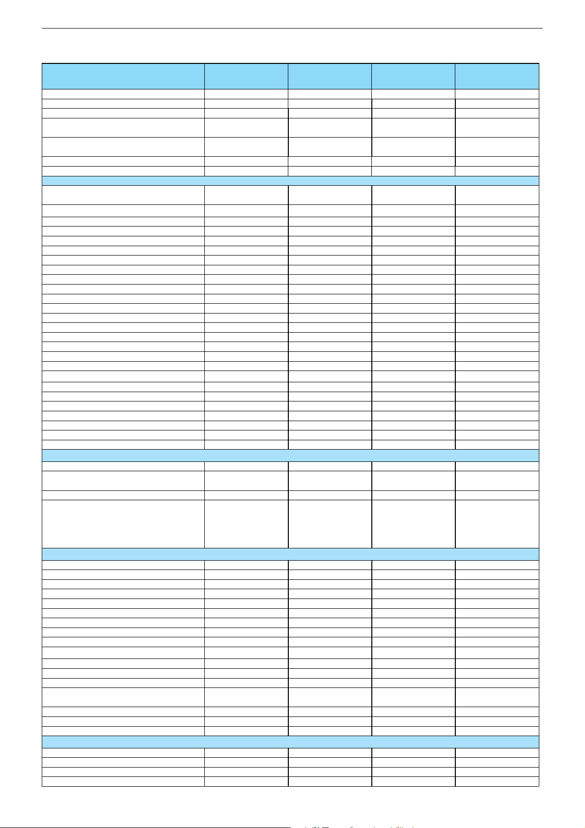
Technische Daten / Technical Data
Chassis D5GRUNDIG Service
Order Number
EAN
Colour
Destination
User manual languages
Sound
Remote Control
PICTURE
Size / Type
Real flat / Super flat
Deflection
100 Hz Picture-/32 kHz line frequency
Flicker free scanning (full frame memory)
Digital Color Transition Improv. (DCTI)
Digital Combfilter
Digital Luminace Transition Improv. (DLTI )
Picture Noise Reduction
SVM (Scan Velocity Moduladion)
Dynamic Focus
Preset picture modes
Tilt
Picture Formats
PIP (2 Tuner)
Multifold Tuner scan (Mosaic Picture)
PAT: Split screen (PICTURE + TEXT)
PAP: Double Window (PICTURE + PICTURE)
2
P
AT: Double window + TXT
POP: PICTURE on PICTURE
Picture freezing
Zoom with point function
Auto 16:9 selection via Scart
Automatic Color Standard Detection
Sharpness control
Blue Background
CHASSIS
TV-Chassis
Tuner
µ-Processor
Keyboard
ELECTRONIC
Stand by indicator
Manual & autom. labeling of prog.
Programable off timer
Programable on timer
Intelligent chanel search (Zapping funct.)
Program Edit
Intelligent Programme Switch
Auto switch off
Program memory TV/AV (opt.)
Teletext/Fasttext/Toptext
Teletext options
Teletext SWAP
Childlock
Menue languages OSD
SWAP (Recall function)
Service mode
Hotel mode
TUNING
Autom. Tuning System with country selection
Frequency Based Auto Search
Automatic Micro-search
Automatic Programing
Davio 14
TVD 37-2401 Text
UV2
GBC3200
40 13833-59703 2
procon silver
D, NL, DK, N, FIN, S,
E, P, ROW
D, GB, NL, DK, N, S,
FIN, E, P
MONO
Davio 14
TVD 37-2501 FR/Text
GBC5900
40 13833-59798 8
procon silver
F
F
MONO
RC 45 C / TP 165 C RC 45 C / TP 165 C
37 cm (14"), FST,
(4:3)
\
90°
\
\
\
\
\
\
\
\
\
\
\
\
\
\
\
\
\
\
\
[
[
[
\
37 cm (14"), FST,
(4:3)
\
90°
\
\
\
\
\
\
\
\
\
\
\
\
\
\
\
\
\
\
\
[
[
[
\
D5 (50 Hz) 90° D5 (50 Hz) 90°
PLL frequency
synthesizer tuning
Philips UOC OM836x
10 keys; TV/DVD,
menue, prog/vol,
plus, minus, eject,
play/pause, stop,
skip-fw, skip-bw
red LED
5 character
[
[
\
[
\
[
100/AV
1 page /
\ / \
\
\
[
7 languages:
D, GB, F, I, E, P, NL
[
[
PLL frequency
synthesizer tuning
Philips UOC OM836x
10 keys; TV/DVD,
menue, prog/vol,
plus, minus, eject,
play/pause, stop,
skip-fw, skip-bw
red LED
5 character
[
[
\
[
\
[
100/AV
1 page / \ / \
\
\
[
7 languages:
D, GB, F, I, E, P, NL
[
[
\\
[
\
[
\
[
\
[
\
Elegance 21
TVD 55-2401/5 Top
UV3
GBC3300
40 13833-59104 9
procon silver
D, I, NL, DK, N, FIN,
S, E, P, ROW
D, GB, I, NL, DK, N,
S, FIN, E, P
STEREO
Elegance 21
TVD 55-2501 FR/Top
GBC6000
40 13833-59799 5
procon silver
F
F
STEREO
RC 45 C / TP 165 C RC 45 C / TP 165 C
55 cm (21"), FST,
(4:3)
[
/ \
90°
\
\
\
\
\
\
\
\
\
\
\
\
\
\
\
\
\
\
\
[
[
[
\
55 cm (21"), FST,
(4:3)
[ / \
90°
\
\
\
\
\
\
\
\
\
\
\
\
\
\
\
\
\
\
\
[
[
[
\
D5 (50 Hz) 90° D5 (50 Hz) 90°
PLL frequency
synthesizer tuning
Philips UOC OM836x
10 keys; TV/DVD,
menue, prog/vol,
plus, minus, eject,
play/pause, stop,
skip-fw, skip-bw
red LED
5 character
[
[
\
[
\
[
100/AV
\ / \ / 7 pages
\
\
[
7 languages:
D, GB, F, I, E, P, NL
[
[
PLL frequency
synthesizer tuning
Philips UOC OM836x
10 keys; TV/DVD,
menue, prog/vol,
plus, minus, eject,
play/pause, stop,
skip-fw, skip-bw
red LED
5 character
[
[
\
[
\
[
100/AV
\ / \ / 7 pages
\
\
[
7 languages:
D, GB, F, I, E, P, NL
[
[
\\
[
\
[
\
[
\
[
\
1 - 3
Page 4

Chassis D5GRUNDIG Service
Manual fine tuning
Direct chanal selection
PAL/BG
SECAM/L´/L
NTSC-Playback via Scart (3,58/4,43)
Cable TV / Hyperband (S1-S41)
AUDIO
Mono/Stereo/Nicam
AV Stereo
Virtual Dolby
Subwoofer
Dynamic Bass
DSP (Digital Sound Processor)
Balance Adjustment
AVL (Audio Volume Level)
PIP listening via Headphone jack
Equalizer
Space Sound Effect
Audio mode
Audio amplifier without extern LS
Tweeter (2 way speaker system)
DVD
4:3 / 16:9 / letterbox format
Dolby Digital
Disc formats:
DVD R/RW (+/-)
CD-R
CD-RW
Media formats:
DVD-Video
VCD
SVC
CD-Audio
CD-ROM
Freeze / Zoom
Coaxial / Optical audio out
Region Code
POWER SUPPLY / CABINET
Power voltage
Power switch
Power consumption
Cabinet (WxHxD, cm) / Weight
FRONT PANEL CONNECTIONS
Headphones
Cinch-AV socket
S-Video
REAR PANEL CONNECTIONS
Euro-AV-Socket AV1
Euro-AV Socket AV2
Euro-AV Socket AV3
S-Video
Digital Audio out
Audio out
Antenna for terrestial reception
Power supply plug
SUPPLIED ACCESSORIES
Remote control (incl. battery)
Power cord
Telescopic antenna
Instruction manual
Warranty info
Davio 14
TVD 37-2401 Text
UV2
[
[
[
\
[
[
[
/ \ / \[ / \ / \
[
\
\
\
\
\
[
\
\
\
\
2 x 5 W (RMS)
\\
[
[
[[
[
[
[[
[
[
[
JPEG, MP3 playback[JPEG, MP3 playback
[
/ [
[ / \
Factory setting: RC 2 Factory setting: RC 2
230V~, 50/60 Hz
[
55 W, standby 2 W in
accordance to
IEC 62087-2002
39,1 x 39,5 x 38,2 cm
approx. 12,3 kg
[ , position lateral [ , position lateral
3 x Cinch - Video in,
Audio L/R in
(position lateral)
\
CVBS in-/output,
RGB input
\
\
\
Yes, coaxial
\
1 x Coaxial-socket for
TV-tuner-in, according
to DIN 45325
\\
[
\ / fix mounted
[
[
[[
Davio 14
TVD 37-2501 FR/Text
[
[
[
[
[
[
[
\
\
\
\
\
[
\
\
\
\
2 x 5 W (RMS)
[
[
[
[
[
[
[ / [
[ / \
230V~, 50/60 Hz
[
55 W, standby 2 W in
accordance to
IEC 62087-2002
39,1 x 39,5 x 38,2 cm
approx. 12,3 kg
3 x Cinch - Video in,
Audio L/R in
(position lateral)
\
CVBS in-/output,
RGB input
\
\
\
Yes, coaxial
\
1 x Coaxial-socket for
TV-tuner-in, according
to DIN 45325
[
\ / fix mounted
[
[
Elegance 21
TVD 55-2401/5 Top
UV3
[
[
[
\
[
[
[
/ [ / [[ / [ / [
[
\
\
\
\
\
[
\
\
\
\
2 x 8 W (RMS)
\\
[
/ [ / [
[
[[
[
[
[[
[
[
[
JPEG, MP3 playback[JPEG, MP3 playback
/ [
[
[ / \
Factory setting: RC 2 Factory setting: RC 2
230V~, 50/60 Hz
[
73 W, standby 2 W in
accordance to
IEC 62087-2002
61,1 x 46,4 x 52,6 cm
approx. 24,6 kg
[ , position lateral [ , position lateral
3 x Cinch - Video in,
Audio L/R in
(position lateral)
\
CVBS in-/output,
RGB input
CVBS in-/output,
S-Video input
\
\
Yes, coaxial
\
1 x Coaxial-socket for
TV-tuner-in, according
to DIN 45325
\\
[
\ / fix mounted
\
[
[[
Elegance 21
TVD 55-2501 FR/Top
[
[
[
[
[
[
[
\
\
\
\
\
[
\
\
\
\
2 x 8 W (RMS)
[ / [ / [
[
[
[
[
[
[ / [
[ / \
230V~, 50/60 Hz
[
73 W, standby 2 W in
accordance to
IEC 62087-2002
61,1 x 46,4 x 52,6 cm
approx. 24,6 kg
3 x Cinch - Video in,
Audio L/R in
(position lateral)
\
CVBS in-/output,
RGB input
CVBS in-/output,
S-Video input
\
\
Yes, coaxial
\
1 x Coaxial-socket for
TV-tuner-in, according
to DIN 45325
[
\ / fix mounted
\
[
1 - 4
Page 5
Chassis D5GRUNDIG Service
(
)
g
g
g
g
g
g
g
g
g
g
g
g
g
g
y
g
g
p
p
p
p
g
g
gung
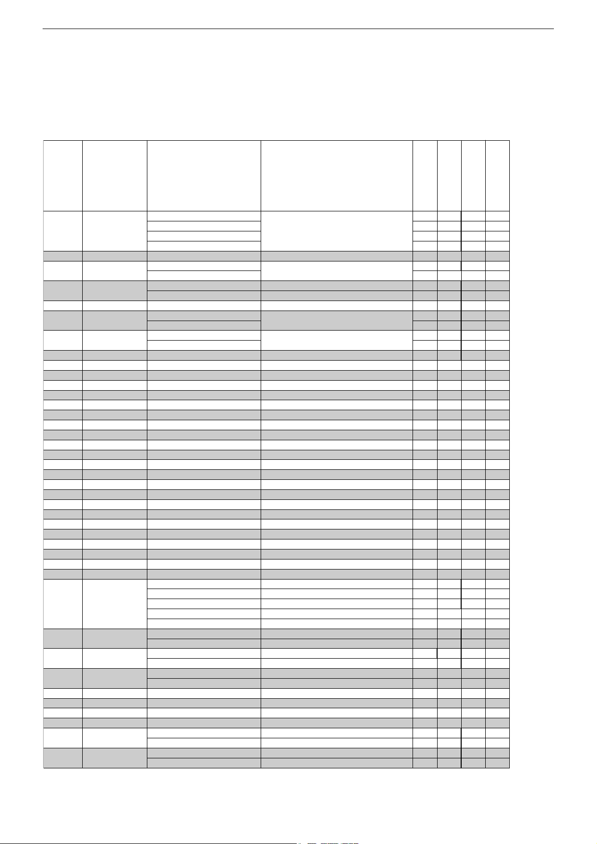
Service- und Sonderfunktionen
Service Mode aktivieren: Taste " i " (Hauptmenü) drücken –> Ser-
vice Code "8500" eingeben.
Service Mode beenden: Taste "TXT" drücken.
1. Grundeinstellwerte
Folgende Tabelle zeigt alle typenbezogenen Grundeinstellungen im
Service Mode. Alle mit * gekennzeichneten Werte müssen zusätzlich nach Abgleich (Seite 2-1) eingestellen werden.
SERVICE
P+/P–
0
1
2
3
4
5
6
7
8
9
10
11
12
13
14
15
16
17
18
19
20
21
22
23
24
25
26
27
28
29
30
31
32
33
34
35
36
37
38
39
Menüpunkt
Point of Menu
P+/P–
TUNER
AGC
STD
EEPE
PEAK
HEAD
SCRN
GRN
RED
BLUE
BLOG
BLOR
YDLY
SAT
HUE
CON
CDR
BRI
EWT
EWCU
EWCL
EWPW
HSHT
EWW
VAMP
SCOR
VSHT
VSLP
RGB
VZOM
SSTD
STYP
TOPTEXT
TXT table
PWLT
IFOF
HPAR
HBOW
HOTEL
SUBWOOFER
PANASONIC
PHILIPS
SHARP
TEMIC
siehe Abgleich / see Adjustment
STD-BY On
STD-BY Off
00
01
siehe Ab
YES
NO
ON
OFF
siehe Abgleich / see Adjustment
siehe Ab
siehe Abgleich / see Adjustment
siehe Ab
siehe Abgleich / see Adjustment
siehe Abgleich / see Adjustment
siehe Abgleich / see Adjustment
siehe Ab
siehe Abgleich / see Adjustment
siehe Ab
siehe Abgleich / see Adjustment
siehe Ab
siehe Abgleich / see Adjustment
siehe Ab
siehe Abgleich / see Adjustment
siehe Ab
siehe Abgleich / see Adjustment
BG-ONLY
I-ONLY
BG + DK
BG + LL'
ALL SYS.
NICAM On
NICAM Off
YES
NO
WEST
EAST
siehe Abgleich / see Adjustment
siehe Ab
ON
OFF
YES
NO
Einstellung
Adjustment
/
Thomson
leich / see Adjustment
leich / see Adjustment
leich / see Adjustment
leich / see Adjustment
leich / see Adjustment
leich / see Adjustment
leich / see Adjustment
leich / see Adjustment
leich / see Adjustment
eingebauten Tuner wählen
select used tuner
Netzschalter-Ein –> Standby
power switch ON –> standby
EEPROM-Reset
Bildschärfe / Peakin
Kopfhörer / Headphone
benötigt für Schirmgitter-Abgleich
used for screen adjustment
Grün-Pe
Rot-Pe
Blau-Pe
Grün / Green cut off
Rot / Red cut off
Luminanz-Verzö
Farbsättigung / Saturation
Bildschärfe / Sharpness
Kontrast / Contast
Kathode-Pe
Helli
Ost/West Tra
Ecken oben / Upper corner
Ecken unten / Lower corner
Ost/West Parabel 4:3 / East west parabola width 4:3
Bild
Bildbreite / Horizontal width
Bildhöhe / Vertical am
S-Korrektur / S correction
Bild
Bildmitte / Vertical slope
OSD Helli
Vertikal Zoom / Vertical zoom
Strahlstrombegrenzung / Peak white limitin
Offset ZF-Demodulator / Offset IF demodulator
Schräglage vertikal / Horizontal parallelogram
Horizontale Bie
Service and Special Functions
Start of the Service Mode: Press button " i " (Main Menu) –> Enter
Service Code "8500".
End the Service Mode: Press button "TXT".
1. Basic Settings
The following table shows all type specific basic settings in the service mode. In addition all values marked with * must be adjusted
according to adjustment (page 2-1).
Hinweis
Hint
el / Green level
el / Red level
el / Blue level
erung / Luminance dela
el / Cathode drive level
keit / Brightness
ez / East West Trapezium
osition horizontal / Horizontal shift
litude
osition vertikal / Vertical shift
keit / Brightness
/ Horizontal bow
DAVIO 14
TVD 37-2401 Text
DAVIO 14
TVD 37-2501 FR/Text
ELEGANCE 21 Flat
TVD 55-2401/ 5 Top
35 35 35
XXX
X
X
32
X
X
32*
30*
30*
30*
36*
14
20
32
32
02
32
28*
32*
32*
17*
32*
60*
35*
25*
28*
34*
01
35*
X
X
X
X
09
32
32*
32*
X
XXX
X
32 32
XX
XX
32*
32*
30*
30*
30*
30*
30*
30*
36*1436*
14
203220
32
320232
02
32
28*3228*
32*
32*
32*
32*
17*
17*
32*
32*
60*
60*
35*
35*
25*
25*
28*
28*
34*0134*
01
35* 35*
X
X
X
X
XX
X
X
093209
32
32*
32*
32*
32*
XX
ELEGANCE 21 Flat
TVD 55-2501 FR/ Top
35
X
X
32
X
X
32*
30*
30*
30*
36*
14
20
32
32
02
32
28*
32*
32*
17*
32*
60*
35*
25*
28*
34*
01
35*
X
X
X
X
09
32
32*
32*
X
X
* Mittelwert / Average Value
1 - 9
Page 6
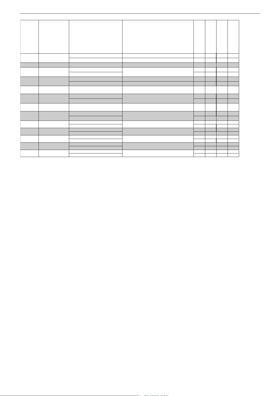
Chassis D5GRUNDIG Service
y
Ä
SERVICE
P+/P–
40
41
42
43
44
45
46
47
48
49
50
51
52
Menüpunkt
Point of Menu
P+/P–
CRT
TEST
AAV
PAL
EWP1
DBAS
VOL
SCART 2
F-AV
F-SVHS
AV ST CURVE
NTSC
OPENNING
Einstellung
Adjustment
/
4:3
16:9
siehe Abgleich / see Adjustment
YES
NO
YES
NO
siehe Abgleich / see Adjustment
YES
NO
siehe Abgleich / see Adjustment
ON
OFF
ON
OFF
ON
OFF
HIGH
LOW
YES
NO
YES
NO
Hinweis
Hint
automatische AV -Umschaltung
automatic AV switching
nur PAL / PAL onl
andere Versionen / other versions
16:9 Ost/West Parabel (für 4:3 Geräte)
16:9 East west parabola width (for 4:3 sets)
Dynamik-Bass / Dynamic bass
Volume Pegel
Volume level
SCART - 2
Front - AV
Front - SVHS
ndert Linearität bei Lautstärke +/Changes linearity of volume +/NTSC Wiedergabe
NTSC Playback
DAVIO 14
TVD 37-2401 Text
DAVIO 14
TVD 37-2501 FR/Text
ELEGANCE 21 Flat
TVD 55-2401/ 5 Top
ELEGANCE 21 Flat
TVD 55-2501 FR/ Top
XXX
35*X35*
35*
X
X
X
08*
08* 08*
X
XX
50
50 50
X
X
XX
X
XXXXX
XXX
XXXX
X
35*
X
X
X
X
08*
X
50
X
X
X
X
X
X
X
* Mittelwert / Average Value
2. Programmsuchlauf (ATS)
Tasten " i " (Hauptmenü) –>P+ /
P+ / P–
"PROGRAMMSUCHLAUF" –> "OK"–>P+ /
P–
"SUCHLAUF" –> "OK"–>
P–
/ / Land
auswählen und mit "OK" Suchlauf starten.
Das automatische Sendersuchsystem stoppt bei jedem empfangswürdigen Sender (AFC und Koinzidenz) und speichert automatisch
die entsprechenden Senderdaten mit dem jeweiligen Standard. Danach wird der Suchlauf fortgesetzt.
Tastendruck "
i " bricht den ATS-Lauf ab.
3. Software-Versionsnummer
Die Software-Versionsnummer wird nach Beenden des Service Modes angezeigt:
VER SD5965_G02
OF96
T01031711
Sicherheits-Hinweis
Die in den Fernsehgeräten auftretende Röntgenstrahlung entspricht
den Bestimmungen der Physikalisch-Technischen Bundesanstalt
vom 8. Januar 1987.
Die Hochspannung für die Bildröhre und die damit auftretende
Röntgenstrahlung ist abhängig von der exakten Einstellung der
Netzteilspannung +B.
Nach jeder Reparatur im Netzteil oder in der Horizontalablenkung
ist die Hochspannung zu messen und gegebenenfalls einzustellen.
Schutzschaltungen im Gerät dürfen nur kurzzeitig außer Betrieb gesetzt werden, um Folgeschäden am Chassis oder an der Bildröhre
zu vermeiden.
Beim Austausch der Bildröhre dürfen nur die in den Ersatzteillisten
vorgeschriebenen Typen verwendet werden.
2. Autoprogram (ATS)
Buttons " i " (Main menu) –>P+ /
"AUTOPROGRAM" –> "OK"–>P+ /
P–
"SETUP" –> "OK"–>P+ /
P–
/ / select Country and
P–
start search with "OK".
The autoprogram system stops at every station of acceptable reception quality (AFC and coincidence) and stores the station data
and the respective standard automatically. The system then continues searching.
Pressing the "
i " button stops the ATS function.
3. Software Version Number
The software version number is shown after ending the service
mode:
VER SD5965_G02
OF96
T01031711
Safety Advice
The X-radiation developing in the sets conforms to the X-radiation
Regulations (January 8, 1987), issued by the Physikalisch-Technische Bundesanstalt (federal physiotechnical institution).
The high tension for the picture tube and thus the developing X-radiation depends on the precise adjustment of the +B power supply.
After every repair of the power supply unit or the horizontal deflection stage it is imperative that the EHT for the picture tube is
checked and re-adjusted if necessary.
To avoid consequential damages to the chassis or the picture tube
the integrated protective circuits are allowed to be put out of operation only for a short time.
When replacing the picture tube use only the types specified in the
spare parts lists.
1 - 10
Page 7

Chassis D5GRUNDIG Service
IC Data Sheets & Specifications
IC 101 - OM 8365
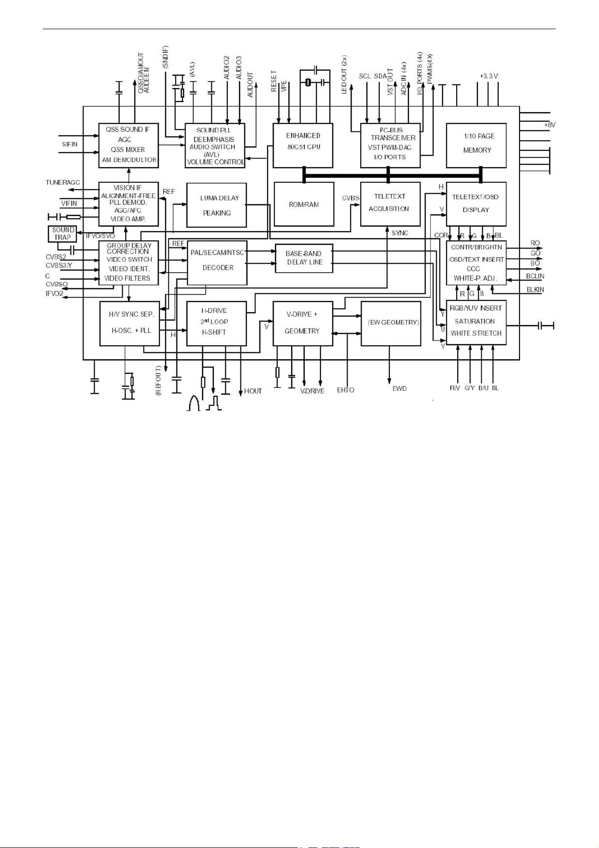
The OM8365H combine the functions of a video processor together
with a µ-Controller, US Closed Caption decoder and Teletext decoder. The Teletext decoder has an internal RAM memory for 10 page
text. The ICs are intended to be used in economy television receivers with 110° picture tubes. The ICs have supply voltages of 8V
and 3.3V and they are mounted in a QFP 80 envelope.
TV-Signal Processor
• Multi-standard vision IF circuit with alignment-free PLL demodula-
tor.
• Internal (switchable) time-constant for the IF-AGC circuit.
• The QSS and mono FM functionality are both available so that an
FM/AM TV receiver can be built without the use of additional ICs
• The mono intercarrier sound circuit has a selective FM-PLL de-
modulator which can be switched to the different FM sound frequencies (4.5/5.5/6.0/6.5MHz). The quality of this system is such
that the external band-pass filters can be omitted.
• The FM-PLL demodulator can be set to centre frequencies of
4.74/5.74MHz so that a second sound channel can be demodulated. In such an application it is necessary that an external bandpass filter is inserted.
• The vision IF and mono intercarrier sound circuit can be used for
the demodulation of FM radio signals.
• Video switch with 2 external CVBS inputs and a CVBS output.
One of the CVBS inputs can be used as Y/C input.
• 2 external audio inputs. The selection of the various inputs is cou-
pled to the selection of the CVBS signals.
• Integrated chrominance trap circuit.
• Integrated luminance delay line with adjustable delay time.
• Picture improvement features with peaking (with switchable cen-
tre frequency, depeaking, variable positive/negative overshoot ratio and video dependent coring) and white stretching.
• Switchable group delay correction in the CVBS path.
• Integrated chroma band-pass filter with switchable centre fre-
quency.
• Switchable DC transfer ratio for the luminance signal.
• Only one reference (12MHz) crystal required for the µ-Controller,
Teletext- and the colour decoder.
• Multi-standard colour decoder with automatic search system.
• Internal base-band delay line.
• Indication of the Signal-to-Noise ratio of the incoming CVBS si-
gnal.
• A linear RGB/YUV/YPBPR input with fast blanking for external
RGB/YUV sources. The synchronisation circuitcan be connected
to the incoming Y signal. The Text/OSD signals are internally
supplied from the µ-Controller / Teletext decoder.
• RGB control circuit with ‘Continuous Cathode Calibration’, white
point and black level off-set adjustment so that the colour temperature of the dark and the light parts of the screen can be chosen
independently.
• Contrast reduction possibility during mixed-mode of OSD and
Text signals.
• Adjustable ‘wide blanking’ of the RGB outputs.
• Horizontal synchronization with two control loops and alignment-
free horizontal oscillator.
• Vertical count-down circuit.
• Vertical driver optimized for DC-coupled vertical output stages.
• Horizontal and vertical geometry processing.
• Horizontal and vertical zoom function for 16:9 applications.
• Horizontal parallelogram and bow correction for large screen pic-
ture tubes.
• Low-power start-up of the horizontal drive circuit.
µ-Controller
• 80C51 µ-controller core standard instruction set and timing.
• 1 µs machine cycle.
• 64 - 96Kx8-bit late programmed ROM.
• 12Kx8-bit DataRAM (shared between Display, Acquisition and
Auxiliary RAM).
• Interrupt controller for individual enable/disable with two level
priority.
• Two 16-bit Timer/Counter registers.
• One 16-bit Timer with 8-bit Pre-scaler.
• WatchDog timer.
• Auxiliary RAM page pointer.
• 16-bit Data pointer.
• Stand-by, Idle and Power Down modes.
• 14 bits PWM for Voltage Synthesis Tuning.
• 8-bit A/D converter with 4 multiplexed inputs.
• 5 PWM (6-bits) outputs for control of TV analogue signals.
• 18 general I/O ports.
Data Capture
• Text memory for 10 pages.
• Inventory of transmitted Teletext pages stored in the Transmitted
Page Table (TPT) and Subtitle Page Table (SPT).
• Data Capture for US Closed Caption.
• Data Capture for 525/625 line WST, VPS (PDC system A) and
Wide Screen Signalling (WSS) bit decoding.
• Automatic selection between 525 WST/625 WST.
• Automatic selection between 625 WST/VPS on line 16 of VBI.
• Real-time capture and decoding for WST Teletext in Hardware, to
enable optimized µ-processor throughput.
• Automatic detection of FASTEXT transmission.
• Real-time packet 26 engine in Hardware for processing accented, G2 and G3 characters.
• Signal quality detector for video and WST/VPS data types.
• Comprehensive teletext language coverage.
• Full Field and Vertical Blanking Interval (VBI) data capture of
WST data Display.
• Teletext and Enhanced OSD modes.
• Features of level 1.5 WST and US Close Caption.
• Serial and Parallel Display Attributes.
• Single/Double/Quadruple Width and Height for characters.
• Scrolling of display region.
• Variable flash rate controlled by software.
• Enhanced display features including overlining, underlining and
italics.
• Soft colours using CLUT with 4096 colour palette.
• Globally selectable scan lines per row (9/10/13/16) and character
matrix [12x10, 12x13, 12x16 (VxH)].
• Fringing (Shadow) selectable from N-S-E-W direction.
• Fringe colour selectable.
• Meshing of defined area.
• Contrast reduction of defined area.
• Cursor.
• Special Graphics Characters with two planes, allowing four colours per character.
• 32 software redefinable On-Screen display characters.
• 4 WST Character sets (G0/G2) in single device (e.g. Latin, Cyrillic, Greek, Arabic).
• G1 Mosaic graphics, Limited G3 Line drawing characters.
• WST Character sets and Closed Caption Character set in single
device.
1 - 11
Page 8
Chassis D5GRUNDIG Service
MSP 34x0G Multistandard Sound Processor Family
The MSP 3410G family of single-chip Multistandard Sound Processors covers the sound processing of all analog TV-Standards
worldwide, as well as the NICAM digital sound standards. The full
TV sound processing, starting with analog sound IF signal-in, down
to processed analog AF-out, is performed on a single chip. This
new generation of TV sound processing ICs now includes versions
for processing the multichannel television sound (MTS) signal conforming to the standard recommended by the Broadcast Television
Systems Committee (BTSC). The DBX noise reduction, or alternatively, Micronas Noise Reduction (MNR) is performed.
Other processed standards are the Japanese FM-FM multiplex
standard (EIA-J) and the FM Stereo Radio standard.
The MSP 3410G has optimum stereo performance without any adjustments.
The MSP 3410G has built-in automatic functions:
The IC is able to detect the actual sound standard automatically
(Automatic Standard Detection). Furthermore, pilot levels and identification signals can be evaluated internally with subsequent switching between mono/ stereo/bilingual; no I2C interaction is necessary (Automatic Sound Selection).
The MSP 3410G can handle very high FM deviations even in conjunction with NICAM processing.
TDA7266S 5+5w Dual Bridge Amplifier
The TDA7266S is a dual bridge amplifier specially designed for TV
and Portable Radio applications.
• Wide supply voltage range (3-18V)
• Minimum external components
– no swr capacitor
– no bootstrap
– no boucherot cells
– internally fıxed gaın
• Stand-by & mute functıons
• Short cırcuıt protection
• Thermal overload protection
TDA 7442 Digitally Controlled Audio Processor
The TDA7442/42D is volume tone (bass and treble) balance (Left/
Right) processors for quality audio applications in TV and Hi-Fi systems. It reproduces surround sound by using a programmable
phase shifter. Control of all the functions is accomplished by serial
bus. The AC signal setting is obtained by resistor networks and
switches combined with operational amplifiers. Thanks to the BIPOLAR/CMOS Technology used, Low Distortion, Low Noise and DC
stepping are obtained.
• 4 stereo inputs
• Input attenuation control in 0.5dB step
• Treble and bass control
• Two surround mode available with 4 selectable responses:
- music
- simulated stereo
• Two speaker attenuators:
- 2 independent speaker controls
• In 1dB steps for balance facility
- independent mute function
• All functions programmable via serial Bus
• 2 monitor output (only for TDA7442)
CXA 2040AQ I2C Bus-Compatible Video Switch
The CXA2040AQ is an I2C bus-compatible 5-input, 3-output video
switch for TVs.
Features
• Serial data control via I2C bus
• 5 composite video input systems
• 2 Y/C (S terminal) input systems
• 3 composite video output systems
• 1 Y/C (S terminal) output system
• Input can be selected independently for each output system.
• SYNC_ID function for CV1 system input
• Built-in 6dB amplifier for CVOUT2 system output
• Built-in Y/C MIX circuit
• Slave address can be changed (90H/92H).
• High impedance maintained by I2C bus line (SDA, SCL) even
when power is OFF.
1 - 12
Page 9
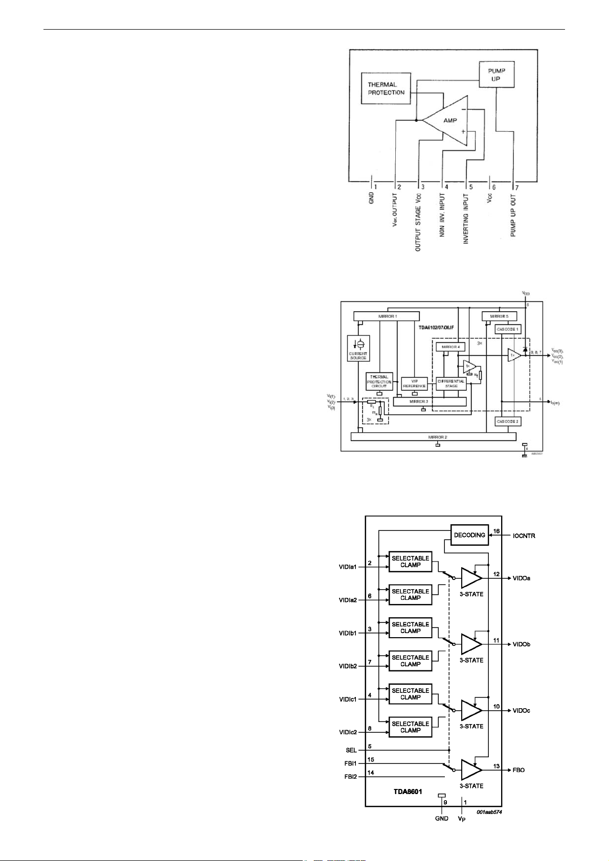
LA7840 Vertical Deflection Output Circuit
Features
• Low power dissipation due to built-in pump-up circuit
• Vertical output circuit
• Thermal protection circuit built in
• Excellent crossover characteristics
• DC coupling possible
General Description
The LA7840 is a vertical deflection output IC for TVs and CRT displays with excellent image quality that use a BUS control system signal processing IC. This IC can drive the direct (even including a
DC component) deflection yoke with the sawtooth wave output from
the BUS control system signal processing IC. Because the maximum deflection current is 1.8 Ap-p, the LA7840 is suited for small
and medium screen sets.
TDA6108 Triple Video Output Amplifiers
By integrating three video amplifiers in a single IC, the TDA6108
ICs provides a single IC solution for driving color TV CRTs. Each
device in the TDA6108 family contains three video output amplifiers
in one plastic DIL-bent-SIL 9-pin medium power (DBS9MPF) package (SOT111-1). Using high-voltage DMOS technology, this enables
each of these ICs to drive the three cathodes of a color CRT directly, providing a significant reduction in the Bill of Materials for
new designs. For maximum performance, the TDA610x amplifiers
should be used with black-current control, enabling automatic black
current stabilization and removing the need for any external alignments on the CRT board.
Chassis D5GRUNDIG Service
TDA8601 RGB/YUV and Fast Blanking Switch
Features
• YUV/RGB and fast blanking switch
• 3-state output
• Selectable clamp:
– passive (with diodes) or active clamp
• Bandwidth greater than 22MHz
• Fully ESD protected
• Latch-up free.
General Description
The device is intended for switching between two RGB or YUV video sources. The outputs can be set to a high-impedance state to
enable parallel connection of several devices. A HIGH level on SEL
(pin 5) selects the video inputs of Channel 2. The IOCNTR control
pin (pin 16) defines the 3-state outputs and clamp inputs:
• HIGH = 3-state outputs (also for test; active clamp)
• LOW = passive clamp at the video inputs (diode)
• Sandcastle: the video signal is clamped with an active clamp during the sync pulse.
1 - 13
Page 10

GRUNDIG Service Chassis D5
Abgleich
Messgeräte: Digitalvoltmeter, Farbbildgenerator.
Servicearbeiten nach Austausch bzw. Reparatur:
– Netzteil: Abgleich 1, 3
– Tuner / ZF: Abgleich 2
– IC401 (EEPROM): Abgleich 2, 4…5
– Bildröhre: Abgleich 3…5
– Bildrohrplatte: Abgleich 3, 5
– Ablenkung: Abgleich 4
1. Spannung B+
– Digitalvoltmeter: D627 Kathode
– Programm: AV
– Helligkeit auf Minimum.
– Spannung B+ mit VR601 entsprechend der Bildröhre einstellen:
Bildröhre B+
A33EKC01X01 111V
A33EKC02X01 111V
A34EAC01X06 111V
A34EJL02X31 111V
2. AGC
– Service Mode aufrufen: Taste " i " drücken –> "8500" eingeben.
– "AGC" mit den Tasten P+ / P- anwählen.
Mit den Tasten / Wert auf 35 einstellen.
– TEST mit den Tasten P+ / P- anwählen.
Mit den Tasten / Wert auf 35 einstellen.
Bild mit 65 dB/µV Antennenpegel auf Störungen, bzw. Kreuzmodulation kontrollieren. Gegebenenfalls Wert/e erhöhen (z.B. 40).
– Service Mode beenden: Taste "TXT" drücken.
3. Screen
– Service Mode aufrufen: Taste " i " drücken –> "8500" eingeben.
– SCRNmit den Tasten P+ / P- anwählen und mit den Tasten / auf
ON stellen. Auf dem Bildschirm wird "BRI 00" angezeigt.
– SCREEN am Dioden-Splitt-Trafo TR501 so einstellen, dass
"BRI 00" gerade sichtbar ist.
– Mit den Tasten / auf Bild zurückschalten (SCRN wird auf OFF
zurückgesetzt).
– Service Mode beenden: Taste "TXT" drücken.
4. Geometrie
– Geometrie-Testbild einspeisen.
– Service Mode aufrufen: Taste " i " drücken –> "8500" eingeben.
– Mit den Tasten P+ / P- die gewünsche Bildgeometrie-Abgleich-
funktion aufrufen und mit den Tasten / die Geometrie einstellen:
– Bildmitte vertikal VSLP. Die untere Bildhälfte ist ausgeblendet.
Den Bildinhalt so einstellen, dass die Mittelline gerade nicht mehr
sichtbar ist.
– Zoom vertikal VZOM.
Bei 16:9 Geräten den Wert auf 35 einstellen.
Bei 4:3 Geräten VZOM so einstellen, dass der Kreis gerade den
Rand berührt. Gegebenenfalls VSLP nochmals korrigieren.
– Bildposition vertikal VSHT.
– Bildlinearität vertikal SCOR.
– Bildhöhe vertikal VAMP.
– Bildposition horizontal HSHT.
– Ost/West-Parabel 4:3 EWPW.
– Ost/West-Trapez EWT.
– Ost/West-Parabel 16:9 EWP1.
– Obere Ecken EWCU.
– Untere Ecken
– Bildbreite bei 4:3 Geräten EWW.
– Schräglage (Parallelogramm) horizontal HPAR.
– Biegung horizontal HBOW.
– Service Mode beenden: Taste "TXT" drücken.
5. Weißabgleich / Cut off
– Testbild Grautreppe einspeisen.
– Service Mode aufrufen: Taste " i " drücken –> "8500" eingeben.
– GRN mit den Tasten P+ / P- anwählen und mit den Tasten / auf
32 stellen.
– REDundBLUEjeweils mit den Tasten P+ / P- anwählen und mit den
Tasten / so einstellen, dass der weiße Bildbereich unbunt ist.
Sollte sich der Weißwert nicht einstellen lassen, Wert für GRN
korrigieren.
– BLOR und BLOG jeweils mit den Tasten P+ / P- anwählen und mit
den Tasten / so einstellen, dass der dunkle Bildbereich unbunt
ist.
– Service Mode beenden: Taste "TXT" drücken.
EWCL.
Bildröhre B+
A34 KPU02XXB 111V
A51ERF135X80 130V
A51ELD032X001 132V
Adjustment
Measuring instruments: Digital voltmeter, colour video generator.
Service works after replacement or repair of the following modules:
– Power supply: adjustment 1, 3
– Tuner / IF: adjustment 2
– IC401 (EEPROM): adjustment 2, 4…5
– CRT: adjustment 3…5
– CRT panel: adjustment 3, 5
– Deflection: adjustment 4
1. Supply Voltage B+
– Digital voltmeter: D627 cathode.
– Programme: AV.
– Brightness control to minimum.
– Adjust voltage B+ the values below the CRT with VR601.
Bildröhre B+
A33EKC01X01 111V
A33EKC02X01 111V
A34EAC01X06 111V
A34EJL02X31 111V
2. AGC
– Start the Service Mode: press button " i " –> enter "8500".
– Call up AGC with buttons P+ / P-.
Adjust the value to 35 with buttons / .
– Call up TEST with buttons P+ / P-.
Adjust the value to 35 with buttons / .
Check picture with 65db/µV aerial level for interferences and crossmodulation respectively. If necessary increase the values (e.g. 40).
– End the Service Mode: Press button "TXT".
3. Screen
– Start the Service Mode: press button " i " –> enter "8500".
– Call up SCRNwith buttons P+ / P- and switch ON with buttons / .
"BRI 00" is shown on screen.
– Adjust SCEEN control at the FPT TR501, that "BRI 00" is just visible.
– Switch back to screen with buttons / (SCRN is reset to OFF).
– End the Service Mode: Press button "TXT".
4. Geometry
– Apply a geometry test pattern.
– Start the Service Mode: press button " i " –> enter "8500".
– Call up the geometry function with buttons P+ / P- and adjust the
geometry with buttons / :
– Vertical slope VSLP. The lower half part of the pattern is blanked.
Adjust picture so that the middle line of the pattern is cut.
– Zoom vertical VZOM.
For 16:9 sets, adjust the value to 35.
For 4:3 sets, adjust the circle of pattern just touches to the upper
an lower edges. Readjust the VSLP if required.
– Vertical shift VSHT.
– Vertical linearity SCOR.
– Vertical amplitude VAMP.
– Horizontal shift HSHT.
– East west parabola width 4:3 EWPW.
– East west trapezium EWT.
– East west parabola width 16:9 EWP1.
– Upper Corner EWCU.
– Lower Corner EWCL.
– Horizontal width for 4:3 sets EWW.
– Horizontal parallelogramm with HPAR.
– Horizontal bow HBOW.
– End the Service Mode: Press button "TXT".
5. White Balance / Cut off
– Apply a Grey Scale Test pattern.
– Start the Service Mode: press button " i " –> enter "8500".
– Call up GRN with buttons P+ / P- and set it to 32 with buttons / .
– Call up RED and BLUE with buttons P+ / P- and adjust the values
so that the white part of the picture becomes achromatic with buttons
/ . If white balance can not be adjusted properly change GRN
value.
– Call up BLOR and BLOG with the buttons P+ / P- and adjust the
values so that the dark part of the picture becomes achromatic with
buttons / .
– End the Service Mode: Press button "TXT".
2 - 1
Bildröhre B+
A34 KPU02XXB 111V
A51ERF135X80 130V
A51ELD032X001 132V
Page 11
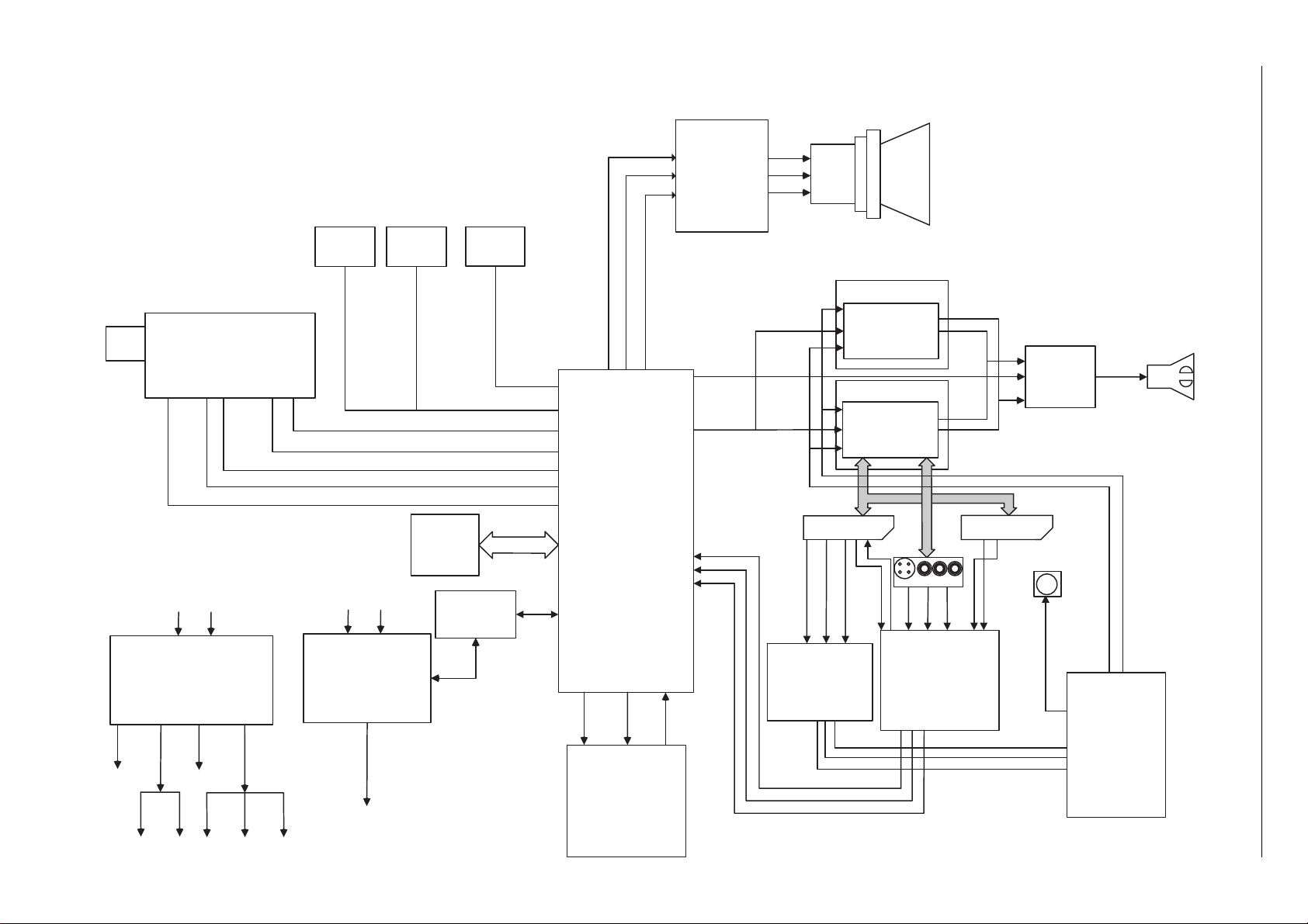
Schaltpläne und Platinenabbildungen / Circuit Diagrams and Layout of the PCBs
GRUNDIG Service Chassis D5
Block Diagram
3 - 1
TUNER
AGC
SCLSDA IF1 IF1
220V AC in
TR 602
DVD
KEYBOARD
195 V
FBT
TR 501
TV
KEYBOARD
EEPROM
24CO8AN
10SI-2.7
IR RECEIVER
IC 401
HORIZONTAL
DEFLECTION
2SD2499
R
G
B
IC 101
TV signal
processor-
Teletext
decoder with
embedded m-
Controller
TDA 6108Q
Triple Video
Output
Amplifier
AOUT
EXT-Y-IN
EXT-C-IN
EXT-V-IN
R
G
B
14" ONLY
IC 203 TDA 7442
21" ONLY
PROCESSOR
IC202 MSP3410G
SCART 1 SCART 2
IC 160
TDA 8601
RGB SWITCH
AUDIO
PROCESSOR
AUDIO
IC 201
CXA 2040AQ
VIDEO SWITCH
Front AV
MUTE
Ro
Lo
POWER AMP.
IC 301
TDA 7266S for 14"
TDA 7266 for 21"
Lo
DVD-L-IN
DVD-R-IN
OPTICAL
OUTPUT
T
U
O
A
21" /130 V
14"/ 111 V
9 V 12 V
14 V
3.3 V
5 V
DVD-Cr
DVD-Y
DVD-Cb
VERTICAL DEFL.
01
EHT
9 V8 V5 V
IC 5
LA 7840
EXT-Y-IN
EXT-C-IN
EXT-V-IN
DVD FFC
CONNECTOR
Page 12
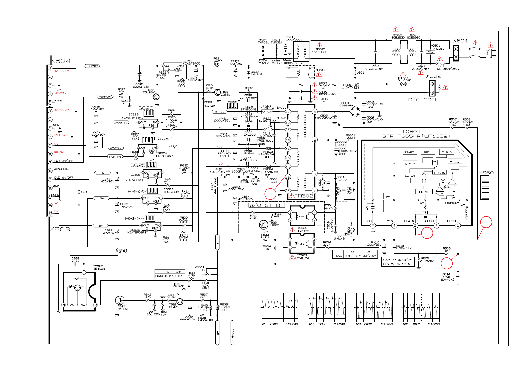
ZL6.190-03 - Netzteil / Power Supply
3 - 2
GRUNDIG Service Chassis D5
4
3
2
1
1
2
3 4
Page 13
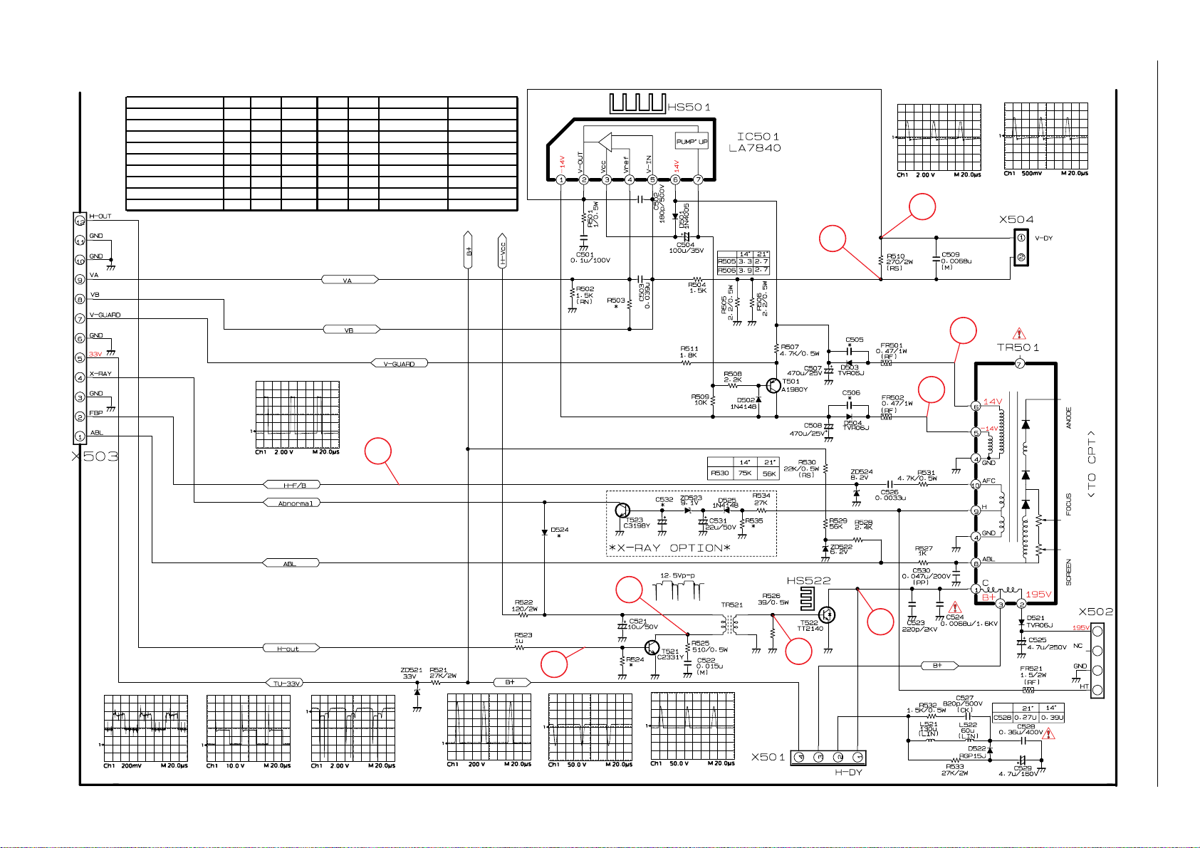
ZL6.190-03 - Ablenkung / Deflection
Bildröhre / CRT +B C524 FR521 R505 R506 TR501 TR602
A33EKC01X01 111V 6.8NF 0.47R 3.9R 3.3R 759551053200 759551053500
A33EKC02X01 111V 6.8NF 0.47R 3.9R 3.3R 759551053200 759551053500
A34EAC01X06 DY-BRZ 111V 6.8NF 1.5R 3.3R 3.9R 759551053200 759551053500
A34EJL02X31 111V 6.8NF 1.5R 3.9R 3.9R 759551053200 759551053500
A34KPU02XXB 111V 6.8NF 1.5R 3.3R 4.7R 759551053200 759551053500
A51EKS41X11 759551056500 759551056400
A51ERF135X80 130V 7.5NF 0.68R 3.3R 2.7R 759551056500 759551056400
A51ELD032X001 (DY)
A51ELD032X001 132V 6.8NF 0.22R 2.7R 2.7R 759551056500 759551056400
3 - 3
132V 7.2NF 0.1R 2.7R 2.7R 759551056500 759551056400
14
GRUNDIG Service Chassis D5
#
$
13
9
10
!
11
6
8
7
5
5
6
7
8
9
0
Page 14
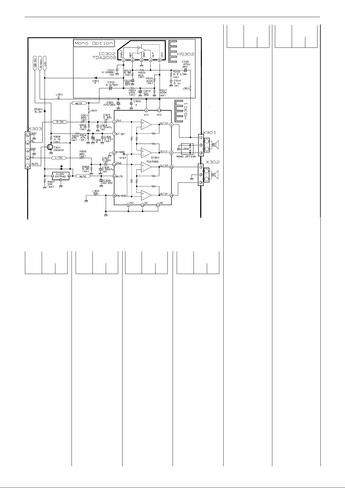
GRUNDIG Service Chassis D5
ZL6.190-03 - NF-Endstufe, AF Amplifier
Koordinaten für die Bauteile der Bestückungsseite (Ansicht von oben)
Coordinates of the Components on the component side (top view)
Pos.-Nr./ Koordinaten/
Pos. No. Coordinates
XY
C301 163 85
C302 163 78
C303 191 34
C304 198 20
C305 164 73
C306 163 67
C307 177 24
C308 193 15
C309 196 34
C310 212 41
C311 203 43
C312 206 54
C313 205 67
C314 179 70
C315 190 60
C501 153 156
C502 158 104
C503 182 133
C504 177 127
C505 201 144
C506 196 144
C507 200 113
C508 195 129
C509 162 161
C521 130 217
C522 122 242
C523 152 225
C524 161 239
C525 211 170
C526 217 135
C527 143 214
C528 115 210
C529 138 169
C530 210 158
C531 214 111
C532 194 101
C601 24 212
C602 36 169
C603 45 148
C604 47 180
C605 74 156
C606 63 227
C607 71 179
C609 96 206
C610 109 231
C611 109 236
Pos.-Nr./ Koordinaten/
Pos. No. Coordinates
XY
C612 74 192
C613 78 221
C614 68 233
C615 109 140
C621 29 99
C622 46 99
C623 10 96
C624 10 76
C625 10 63
C626 77 73
C627 88 77
C628 124 69
C629 104 71
C630 70 95
C631 64 64
C632 121 48
C633 91 49
C634 151 72
C635 67 27
C636 35 16
C637 72 38
C638 81 24
C639 129 89
C640 141 31
C641 121 11
C642 46 23
C643 173 87
C644 112 71
C645 107 57
D302 195 69
D501 173 137
D502 174 111
D503 204 136
D504 193 147
D521 170 241
D522 129 200
D524 125 200
D525 211 105
D601 105 150
D602 100 140
D603 87 198
D621 36 100
D622 40 100
D623 32 87
D624 43 87
D625 77 78
Pos.-Nr./ Koordinaten/
Pos. No. Coordinates
XY
D626 93 85
D627 120 64
D628 100 68
D629 20 69
D630 59 98
D631 108 66
D632 64 78
D633 93 73
D634 14 103
DB601 53 155
E1 9 237
E10 21 169
E11 36 169
E12 31 141
E13 54 137
E14 74 146
E15 74 156
E16 85 241
E17 99 241
E18 85 171
E19 99 171
E2 24 212
E20 115 210
E21 130 210
E22 138 210
E23 134 199
E24 142 199
E25 161 239
E26 161 232
E27 161 217
E28 173 213
E29 173 202
E3 39 212
E30 177 192
E31 202 200
E32 202 207
E33 202 213
E34 82 131
E35 82 106
E36 102 131
E37 97 106
E38 122 131
E39 122 106
E4 47 212
E40 170 78
E41 195 78
3 - 4
Pos.-Nr./ Koordinaten/
Pos. No. Coordinates
XY
E42 170 10
E43 195 10
E44 30 126
E45 54 126
E46 30 105
E47 45 105
E48 136 184
E49 144 184
E5 33 202
E6 46 202
E7 33 187
E8 46 187
E9 14 169
F601 12 221
F621 86 87
F622 89 87
FB601 64 195
FB602 68 195
FB621 124 82
FR501 204 151
FR502 193 151
FR521 199 151
FR623 104 82
FR624 112 82
FR635 142 89
FR636 147 89
IC301 178 44
IC302 188 44
IC303 196 72
IC501 160 126
IC601 74 206
IC621 15 69
IC622 101 36
IC623 46 49
IC624 32 34
IC625 57 53
IC626 87 21
IC627 134 83
IC628 109 193
IC629 113 164
J301 163 61
J302 163 32
J303 199 29
J304 164 22
J305 213 36
Pos.-Nr./ Koordinaten/
Pos. No. Coordinates
XY
J306 196 27
J307 166 39
J308 163 46
J309 163 56
J310 163 59
J311 166 65
J501 151 165
J502 157 165
J503 189 154
J504 196 165
J505 208 119
J506 218 121
J507 203 122
J509 193 97
J510 179 97
J512 215 190
J521 144 188
J601 69 126
J602 97 190
J603 100 167
J621 68 19
J622 26 9
J623 50 18
J624 74 21
J625 77 14
J626 60 31
J627 32 58
J628 59 74
J629 99 64
J630 127 24
J631 128 33
J632 128 40
J633 142 49
J634 155 39
J635 131 101
J636 133 95
J637 137 107
J638 154 88
J639 73 103
J641 57 70
J642 11 120
J643 29 59
L301 75 102
L302 212 9
L521 144 184
L522 142 199
L621 131 65
PT601 14 136
R301 212 22
R302 212 25
R303 163 43
R304 163 37
R305 212 17
R306 212 12
R307 197 83
R308 179 28
R313 213 49
R314 213 47
R315 199 59
R316 212 58
R317 212 61
R318 186 57
R501 159 140
R502 156 127
R503 169 125
R504 167 138
R505 182 142
R506 182 146
R507 180 107
R508 171 119
R509 181 119
R510 154 163
R511 187 94
R521 187 121
R522 122 200
R523 118 200
R524 122 215
R525 117 224
R526 152 242
R527 201 167
R528 189 158
R529 189 161
R530 189 165
R531 217 143
R532 147 199
R533 146 176
R534 212 131
R535 214 125
R601 92 176
R602 96 137
R603 109 223
R604 99 215
R605 74 241
R606 78 217
R607 79 171
R620 38 81
R621 13 83
R622 58 80
R623 58 77
R624 58 84
R625 99 43
R626 43 61
Pos.-Nr./ Koordinaten/
Pos. No. Coordinates
XY
R627 63 34
R628 63 26
R629 70 46
R630 110 42
R631 105 42
R632 100 14
R633 118 177
R634 118 170
R635 94 61
R636 135 79
R637 135 42
R638 150 89
R639 146 24
R640 146 11
R641 127 19
R642 127 16
R643 76 16
R644 124 163
R645 139 157
R646 128 69
R647 81 49
R648 24 69
R649 12 90
R650 12 87
RC601 54 141
RL601 69 106
RL602 21 107
T301 210 30
T501 165 112
T521 117 219
T522 137 221
T523 208 101
T621 52 93
T622 52 88
T623 136 18
T624 114 10
T625 120 37
T626 25 93
T627 25 98
TR501 188 202
TR522 134 233
TR601 33 187
TR602 122 131
TR603 30 126
VD601 30 223
VR601 134 71
X301 158 26
X302 158 14
X303 216 15
X501 160 193
X502 211 143
X503 216 97
X504 162 183
X601 29 240
X602 18 158
X603 43 10
ZD301 168 93
ZD521 187 106
ZD522 171 161
ZD523 208 113
ZD524 218 131
Page 15
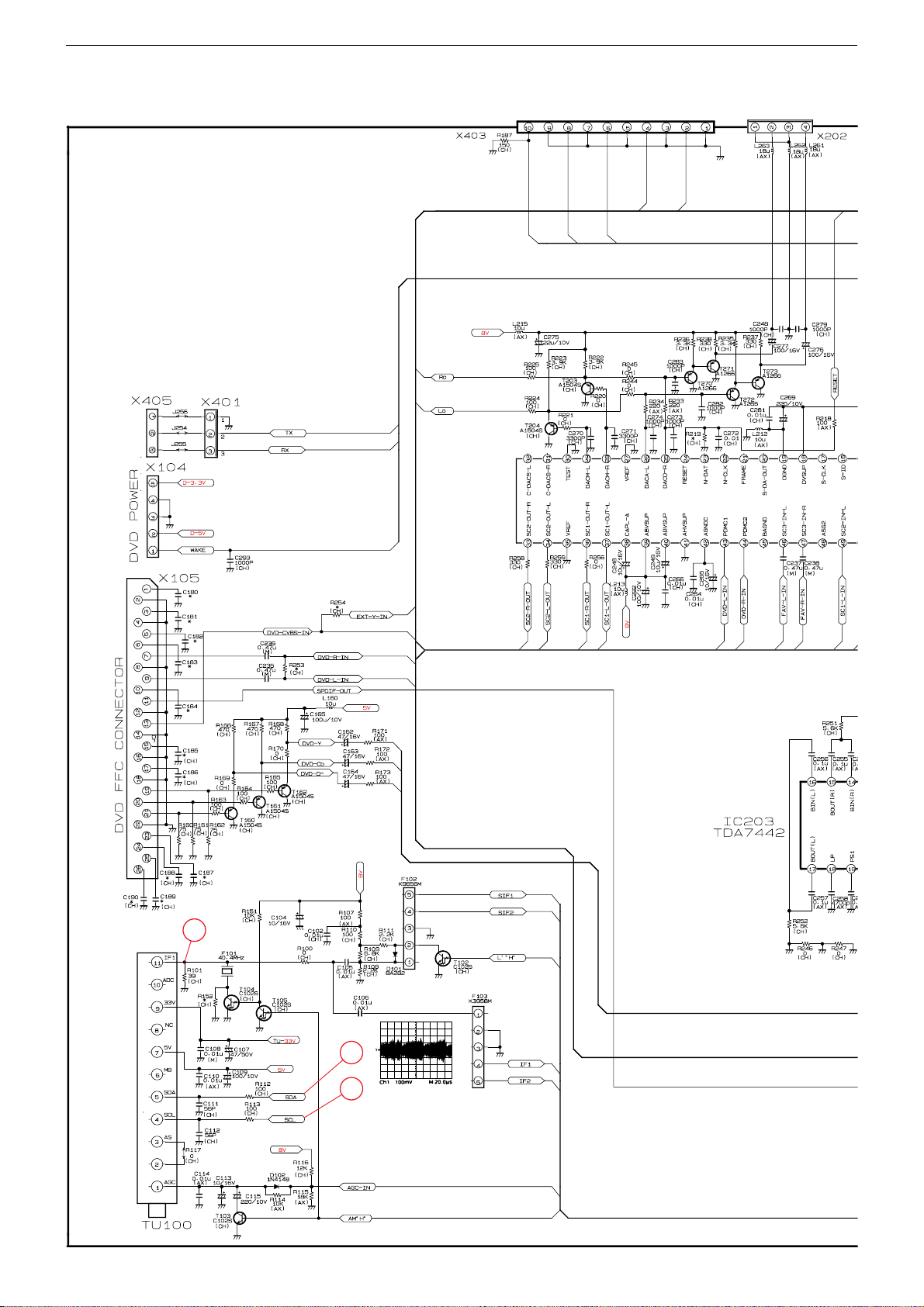
GRUNDIG Service Chassis D5
ZL5.190-03 - Signalverarbeitung / Signal Processing
15
17
16
%
3 - 6
Page 16
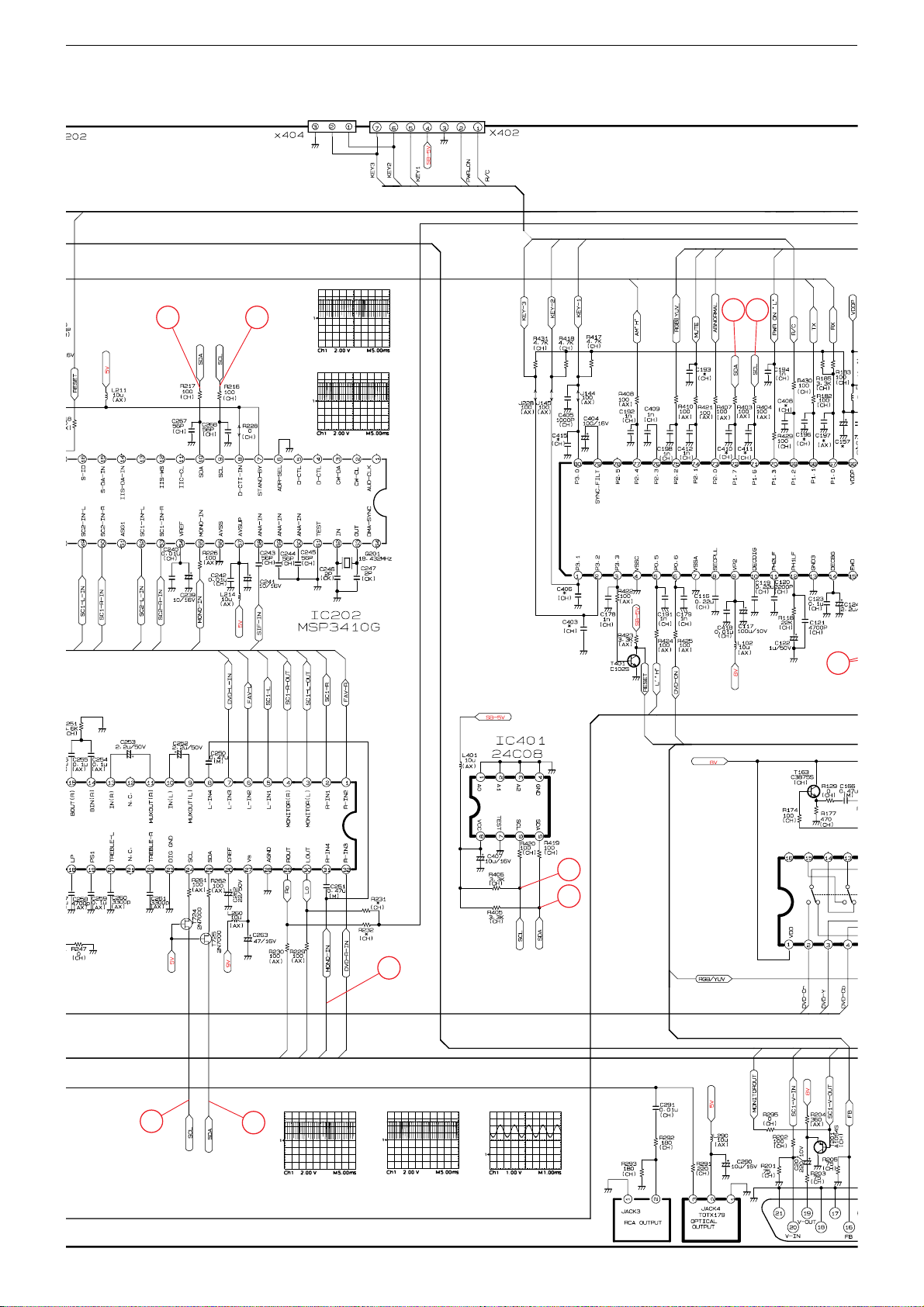
GRUNDIG Service Chassis D5
0V(0V) 3 2V(3 2V)
1617
17 16
^
&
0V(0V)
3,2V(3,2V)
0V(3,2V)
0V(0V)
0V(0,1V)
0V(0V)
3,2V(2,9V)
3,2V(0V)
0V(0V) 0V(2,5V)
2,5V(0V) 5,0V(0V)
7,9V(1,4V) 4,6V(5,0V)
4,9V(0V) 4,7V(5,0V)
2,8V(0V) 0V(3,2V)
3,8V(0V) 4,9V(4,9V)
0V(0V) 3,2V(3,2V)
3,9V(0V) 3,2V(3,2V)
3,2V(3,2V)
3,2V(3,2V)
0,1V(0,1V)
On(Stby)
3,2V(3,2V)
22
16
17
16
17
18
^
&
*
3 - 7
On(Stby)
1,3V(0,5V)
1,5V(0,5V)
1,3V(0,5V)
8,0V(1,4V)
Page 17
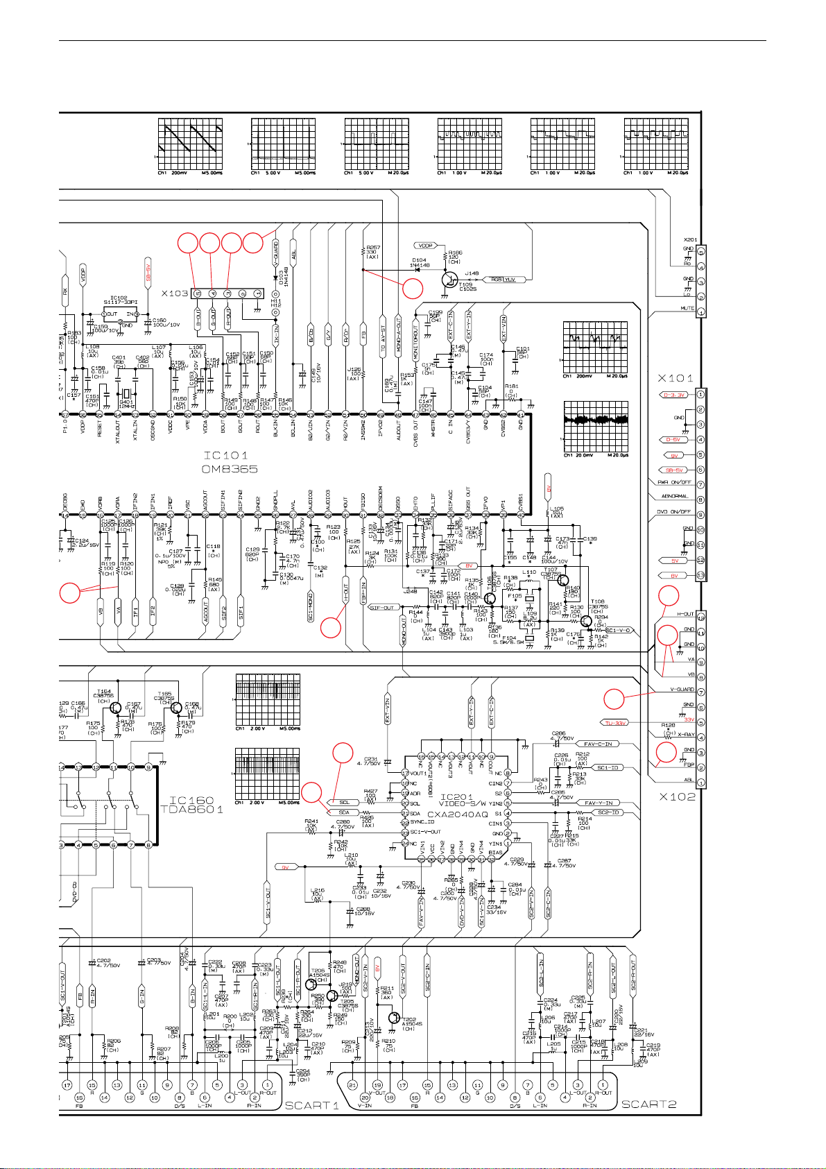
GRUNDIG Service Chassis D5
™ £ §
25 26 27 23
21
)
22
1,5V(0,5V)
3,9V(0V) 3,2V(3,2V)
1,3V(0,5V)
0V(0V) 3,2V(3,2V)
1,2V(0V)
3,2V(2,2V)
0,6V(0V) 0V(0V)
0,6V(0V) 1,7V(1,7V)
1,2V(0V)
1,2V(1,2V)
1,8V(0V) 1,6V(1,6V)
1,2V(0V)
1,2V(1,2V)
1,8V(0V) 0V(3,3V)
1,2V(1,2V)
3,8V(0V) 3,3V(0V)
3,7V(0V) 0V(3,3V)
2,1V(0,8V) 3,2V(0V)
1,8V(0V) 3,5V(0V)
^
&
1,8V(0V) 3,4V(0V)
0V(0V) 3,3V(0V)
1,6V(0V) 5,3V(0V)
0,3V(0,3V) 3,8V(0V)
17
3,6V(0V) 2,2V(0V)
20
3,6V(0V) 2,2V(0V)
16
0,4V(0V) 2,2V(0V)
0,4V(0V) 0,1V(0V)
4,7V(5,0V)
4,6V(5,0V)
3,1V(0V)
2,4V(0V) 2,9V(0V)
4,4V(0V)
8,9V(0V)
2,5V(0V) 3,2V(0V)
On(Stby)
1,9V(0,3V) 2,9V(0,9V)
4,4V(0V)
2,4V(0V) 3,4V(0V)
0V(0V)
2,2V(0,3V) 0,4V(0,2V)
4,4V(0V)
0V(0,7V) 3,3V(0,1V)
4,4V(0V)
4,4V(0V)
2,9V(0V) 0V(0V)
4,4V(0V)
4,4V(0V)
3,3V(0,2V)
7,8V(1,4V)
0V(0V)
4,4V(0V)
0V(0V)
4,4V(0V)
0V(0V)
4,4V(0V)
0V(0V)
4,4V(0V)
¡
3,7V(0V) 0V(0V)
20
22
23
24
3 - 8
Page 18

GRUNDIG Service Chassis D5
Koordinaten für die Bauteile der Bestückungsseite (Ansicht von oben)
Coordinates of the Components on the component side (top view)
Pos.-Nr./ Koordinaten/
Pos. No. Coordinates
XY
C102 86 228
C105 76 226
C106 76 222
C107 88 238
C108 46 219
C109 39 218
C113 5 218
C114 9 240
C115 20 218
C116 67 193
C117 63 192
C119 67 198
C120 67 202
C121 67 206
C122 60 219
C123 67 213
C124 72 218
C127 87 212
C128 91 212
C129 99 220
C130 99 217
C131 99 211
C132 107 225
C133 118 209
C134 113 204
C137 113 200
C138 118 196
C139 113 190
C144 118 223
C145 125 179
C146 125 176
C147 113 183
C149 116 165
C153 100 160
C157 95 153
C159 103 131
C160 103 124
C162 121 81
C163 122 58
C164 120 68
C165 126 48
C166 129 165
C167 126 165
C168 122 165
C169 136 111
C200 61 125
C201 21 193
C202 21 185
C203 21 178
C204 21 172
C207 18 148
C208 18 150
C209 18 168
C210 18 159
C211 29 167
C212 33 152
C213 18 127
C216 16 68
C217 13 68
C218 18 100
C219 18 90
C220 18 104
C221 18 86
C222 18 110
C223 18 115
C224 20 69
Pos.-Nr./ Koordinaten/
Pos. No. Coordinates
XY
C225 20 66
C228 21 203
C229 18 136
C230 81 93
C231 69 125
C232 66 116
C234 55 125
C235 94 86
C236 94 89
C237 84 77
C238 81 77
C239 70 81
C241 65 81
C246 58 79
C247 53 79
C248 107 77
C249 95 77
C250 43 36
C251 56 15
C252 38 36
C253 33 41
C254 28 36
C255 24 36
C256 19 26
C257 19 16
C258 27 9
C259 29 9
C260 32 9
C261 34 9
C262 40 11
C263 46 16
C265 89 82
C269 89 42
C275 99 43
C276 118 18
C277 128 18
C280 49 158
C285 58 102
C286 50 102
C287 18 142
C288 22 56
C289 51 131
C290 20 39
C292 101 82
C401 91 170
C402 96 170
C404 63 185
C407 57 197
D101 90 225
D102 45 238
D103 153 189
D104 116 149
F101 55 219
F102 95 218
F103 83 218
F104 127 194
F105 135 194
IC102 114 126
IC202 52 53
IC203 51 31
J100 22 240
J101 35 243
J102 5 213
J103 53 152
J104 33 204
Pos.-Nr./ Koordinaten/
Pos. No. Coordinates
XY
J105 64 219
J106 68 238
J107 76 236
J108 97 230
J109 104 233
J110 110 228
J111 111 213
J112 133 104
J113 126 215
J114 130 215
J115 133 215
J116 136 215
J117 138 215
J118 136 198
J119 139 198
J120 142 218
J121 146 218
J122 128 233
J123 132 170
J124 132 168
J125 131 143
J126 119 164
J127 131 146
J128 80 89
J129 122 136
J130 122 132
J131 133 108
J132 122 126
J133 122 128
J134 112 136
J135 89 124
J136 112 124
J137 83 139
J138 72 145
J139 72 148
J140 72 150
J141 72 153
J142 83 137
J143 76 161
J144 77 168
J145 72 168
J146 128 87
J147 28 131
J148 40 193
J149 40 186
J150 46 162
J151 43 162
J152 41 162
J153 38 162
J154 28 139
J155 28 136
J156 27 127
J157 28 124
J158 30 117
J159 27 113
J160 27 111
J161 27 108
J162 27 106
J163 59 111
J164 30 93
J165 30 90
J166 30 88
J167 30 85
J168 30 83
J169 14 37
J170 18 145
Pos.-Nr./ Koordinaten/
Pos. No. Coordinates
XY
J171 100 136
J172 53 110
J173 111 49
J174 61 85
J175 16 131
J176 56 111
J177 106 98
J178 108 98
J179 111 98
J180 50 110
J181 97 99
J182 100 99
J183 65 137
J184 122 123
J185 122 121
J186 122 118
J187 122 116
J188 122 113
J190 122 111
J191 45 150
J192 45 147
J193 134 116
J194 118 86
J195 143 25
J196 111 86
J197 108 86
J198 106 86
J199 136 56
J200 92 49
J201 89 49
J202 85 49
J203 83 49
J204 79 49
J205 76 49
J206 45 54
J207 23 15
J208 81 41
J209 67 33
J210 67 31
J211 67 28
J212 61 23
J213 59 38
J214 56 18
J215 47 54
J216 42 55
J217 40 55
J218 36 55
J219 38 50
J220 38 45
J221 132 163
J222 154 158
J223 103 8
J224 101 8
J225 109 8
J226 118 35
J227 135 48
J228 70 168
J229 151 35
J230 65 139
J231 113 98
J232 135 46
J233 140 43
J234 65 142
J235 32 211
JACK3 7 61
JACK4 9 47
Pos.-Nr./ Koordinaten/
Pos. No. Coordinates
XY
L101 76 231
L102 63 200
L103 129 204
L104 122 204
L105 122 215
L106 109 136
L107 107 136
L108 104 136
L109 131 187
L110 139 187
L160 130 43
L200 3 149
L201 18 155
L202 18 153
L203 18 165
L204 18 161
L205 4 79
L206 22 73
L207 20 73
L208 18 97
L209 18 93
L210 61 111
L211 63 41
L212 89 45
L213 103 86
L214 50 42
L215 109 44
L216 16 37
L260 49 10
L261 139 18
L262 136 18
L263 134 18
L290 38 48
L401 57 178
Q201 52 76
Q401 91 174
R104 76 233
R106 76 228
R107 100 233
R114 35 241
R119 77 212
R120 80 212
R125 114 222
R146 113 170
R147 110 170
R148 108 170
R149 105 170
R171 123 87
R172 121 87
R173 126 87
R186 118 124
R204 26 190
R211 26 122
R212 18 207
R218 34 162
R226 65 85
R229 98 16
R230 93 16
R233 111 41
R234 110 38
R241 38 158
R261 78 10
R262 75 10
R403 53 183
R404 53 181
R405 45 191
Pos.-Nr./ Koordinaten/
Pos. No. Coordinates
XY
R406 45 188
R407 80 168
R409 62 165
R410 75 169
R421 64 165
R423 53 178
R424 57 200
R425 59 200
R426 52 162
R427 49 162
SCART1 7 196
SCART2 7 130
T270 128 30
T271 123 24
T272 113 29
T273 118 24
T274 81 18
T275 85 18
TUNER 9 229
X101 118 240
X102 151 230
X103 115 160
X104 150 38
X105 133 97
X201 101 32
X202 139 35
X401 96 141
X402 83 131
X403 94 100
X404 80 125
3 - 11
Page 19

GRUNDIG Service Chassis D5
Koordinaten für die Bauteile der Lötseite (Ansicht von unten)
Coordinates of the Components on the solder side (bottom view)
Pos.-Nr./ Koordinaten/
Pos. No. Coordinates
XY
C101 70 225
C110 32 225
C111 27 225
C112 22 225
C125 78 209
C126 78 207
C135 133 192
C136 120 213
C140 133 204
C141 128 201
C142 125 204
C143 125 207
C150 110 156
C151 108 156
C152 105 156
C154 102 171
C156 102 164
C158 98 155
C161 92 156
C205 13 152
C206 10 152
C214 12 85
C215 12 82
C226 26 210
C227 13 145
C233 63 119
C240 68 78
C242 65 68
C243 62 75
C244 61 68
C245 59 68
C264 92 79
C266 97 68
C267 68 56
C268 66 56
C270 106 48
C271 99 48
C272 92 56
C273 95 56
C274 98 56
C278 131 21
Pos.-Nr./ Koordinaten/
Pos. No. Coordinates
XY
C279 141 21
C281 82 56
C282 117 32
C283 124 32
C284 55 136
C291 14 50
C403 66 186
C405 88 127
C406 66 183
C408 102 127
C418 75 195
IC101 93 190
IC160 124 146
IC201 53 144
IC401 50 200
R100 72 222
R101 49 226
R102 67 225
R103 73 233
R105 67 229
R108 97 222
R109 91 228
R110 89 228
R111 94 228
R112 26 219
R113 24 219
R115 51 241
R116 55 242
R117 16 225
R118 68 209
R121 87 207
R122 102 215
R123 104 205
R124 114 217
R126 69 195
R127 123 193
R128 147 227
R129 129 161
R130 135 183
R131 114 213
Pos.-Nr./ Koordinaten/
Pos. No. Coordinates
XY
R132 117 213
R133 108 200
R134 116 198
R135 121 198
R136 124 201
R137 129 198
R138 132 198
R139 135 185
R140 123 188
R141 123 191
R142 139 184
R143 133 202
R144 125 209
R145 55 240
R150 102 167
R151 50 211
R160 126 69
R161 136 63
R162 126 82
R163 126 66
R164 133 63
R165 126 80
R166 126 56
R167 132 55
R168 122 71
R169 126 59
R170 126 73
R174 131 153
R175 126 153
R176 120 153
R177 129 153
R178 123 153
R179 118 153
R180 79 202
R181 118 187
R182 93 142
R183 93 145
R184 115 206
R185 89 156
R187 55 103
R188 89 221
Pos.-Nr./ Koordinaten/
Pos. No. Coordinates
XY
R200 10 157
R201 15 200
R202 18 200
R203 16 194
R205 16 189
R206 16 184
R207 16 177
R208 16 170
R209 20 139
R210 17 124
R213 23 210
R214 10 145
R215 15 145
R216 66 37
R217 68 37
R219 90 56
R220 101 48
R221 104 48
R222 106 36
R223 106 39
R224 96 35
R225 93 35
R227 63 105
R228 64 48
R231 96 16
R232 91 16
R235 116 27
R236 126 27
R237 117 21
R238 124 21
R239 38 70
R240 87 39
R242 47 155
R243 45 143
R244 106 33
R245 106 31
R246 43 28
R247 40 26
R248 26 56
R249 26 52
R250 33 55
Pos.-Nr./ Koordinaten/
Pos. No. Coordinates
XY
R251 26 45
R252 16 27
R253 89 86
R254 118 105
R291 14 47
R292 14 53
R293 14 56
R294 42 119
R295 42 124
R408 59 186
R417 77 164
R418 75 164
R419 45 199
R420 45 196
R422 37 185
R429 83 169
R430 98 128
R431 72 165
T101 71 229
T102 100 228
T103 18 214
T104 51 214
T105 46 214
T106 125 198
T107 126 185
T108 138 179
T109 119 138
T160 126 63
T161 131 59
T162 126 76
T163 130 158
T164 126 158
T165 121 158
T201 24 197
T202 22 123
T203 101 36
T204 101 40
T205 30 51
T206 30 56
T401 40 190
3 - 12
Page 20
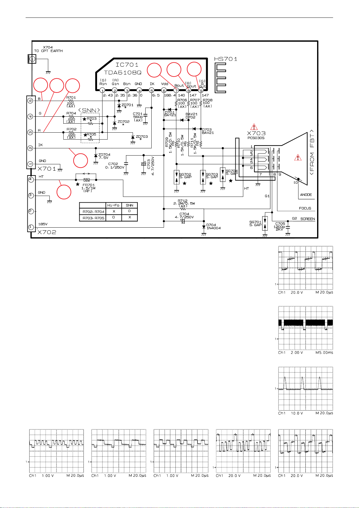
GRUNDIG Service Chassis D5
ZL5.194 - Bildrohrplatte / CRT Board
25
26
32
27
31
28
29
30
º
⁄
¤
§
3 - 13
•
ª
Page 21
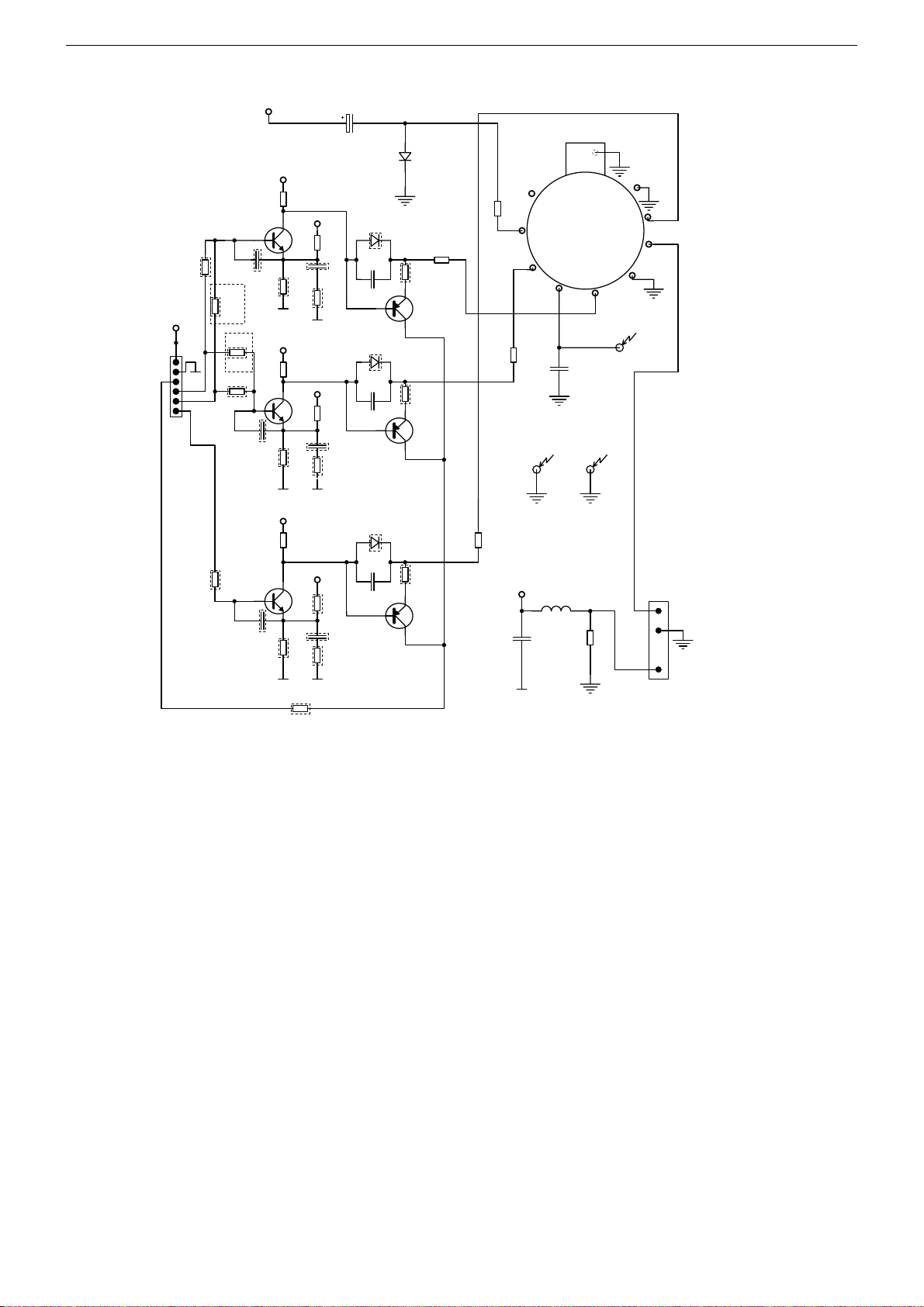
GRUNDIG Service Chassis D5
ZL6.194 - Bildrohrplatte / CRT Board
R707
220R
R706
220R
R703
220R
BF422
C701
47p
C706
47p
C709
47p
T701
155V
R710
15k
R711
390R
R715
15k
R716
390R
R720
15k
R721
390R
155V
crt
155V
T703
BF422
C707 390p
crt
155V
T705
BF422
C710
crt
R701
100R
8V_
R713
2.7k
C703 390p
R712
100R
crt
8V_
R718
2.7k
R717
100R
crt
8V_
R723
2.7k
390p
R722
100R
crt
C702
10u/250V
D702 1N4148
C705
470p
D703
C708
470p
D704
C711
470p
1k
1N4148
1N4148
D701
1N4007
R714
T702
BF421
R719
1k
T704
BF421
R724
1k
T706
BF421
R725
1.5K
R727
1.5K
R709
R726
1.5K
C713
100n/250V
X703
4
n.c.
220R
5
G1
6
GREEN
G2
AQUA SMPS
L701
155V
10uH
R728
100k 1/2W
crt
CRT SOKET
GND
78
RED
C712
2.2n
12
11
10
9
G2
GND
BLUE
HT
HT
X702
1
2
3
3-Nov-2004
CRT
CRT BOARD
R702
220R
8V_
1
2
crt
3
Red
4
Green
5
6
X701
RGB
Blue
Icatch
R704
220R
3 - 14
Page 22
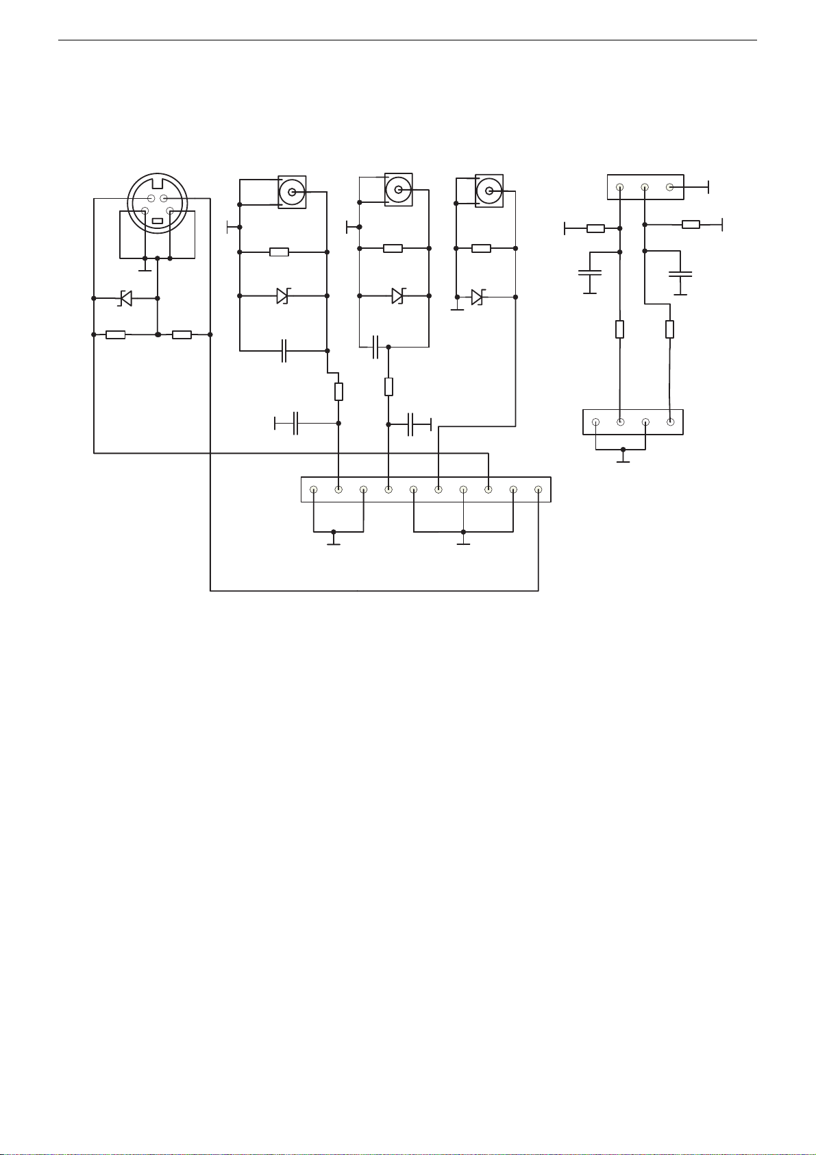
GRUNDIG Service Chassis D5
ZL5.192-01 - AV-Platte / AV Board
1
2
R197
390R
R195
1
3
L
R
2
3
R198
390R
C194
47N
R196
180R 1/2W
4
SVHS
ZD191
6.2
R190
75R
R191
75R
C192
1N
470R
LEFT
LEFT
R193
240K
ZD193ZD192
470R
R200
C195
1N
RIGHT
65 YC
RIGHT
R192
240K
C191
1N
R199
C196
1N
VIDEO
VIDEO
R194
75R
ZD194
6.2
JACK
C193
47N
180R 1/2W
X202-1
X403-1
10
9
2-Nov-2004
1
2
3
4
5
6
7
8
3 - 15
Page 23
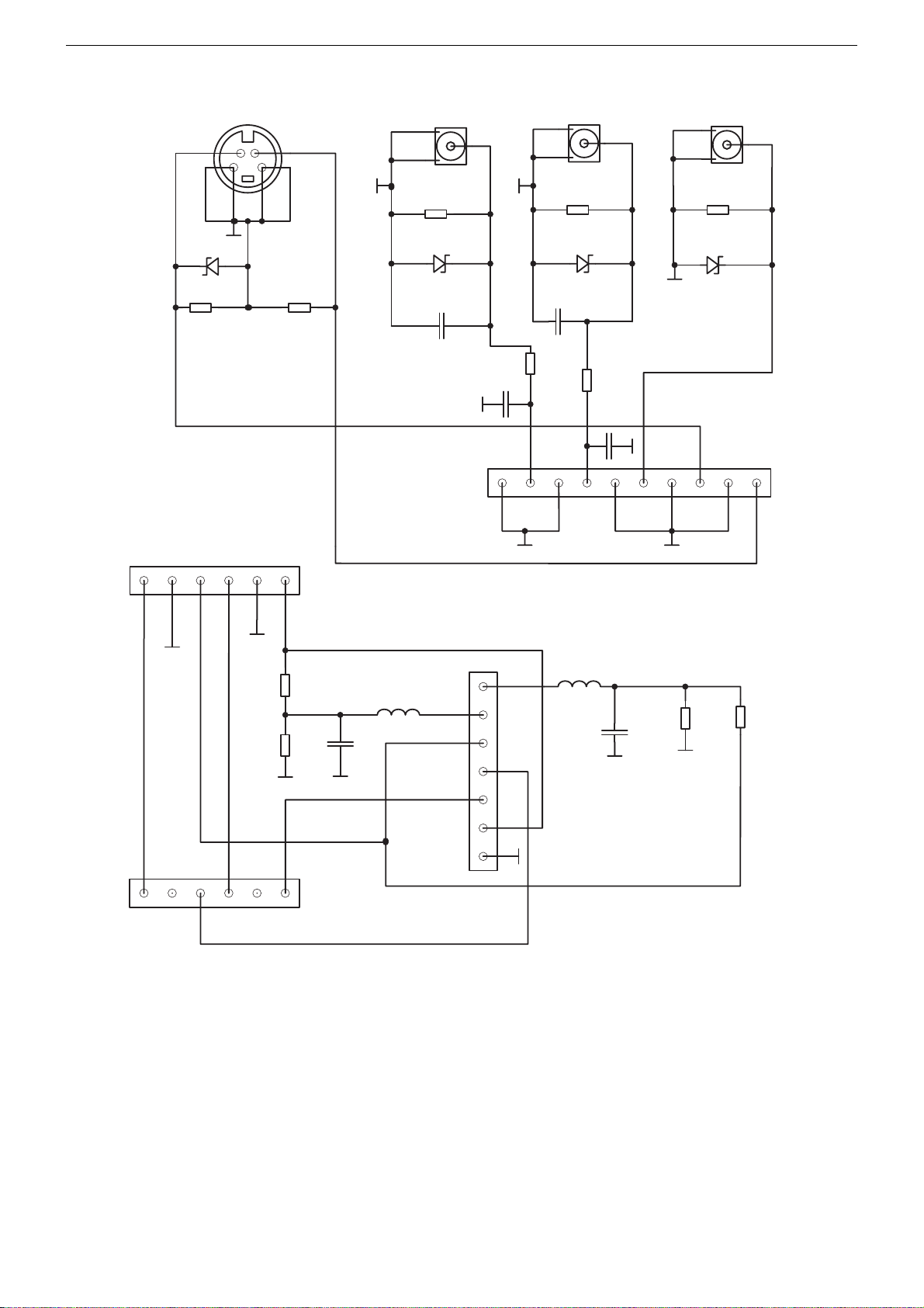
GRUNDIG Service Chassis D5
ZL6.192-02 - AV-Platte / AV Board
SVHS
ZD191
6.2
R190
75R
X301
RR
1
2
3
X902
L
465
R199
470R
1/4W
9
C192
1N
8
X905
LEFT
R193
240K
ZD193
?
R200
470R
1/4W
7
C196
1N
6
5
X904
65 YC
RIGHT
R192
75R
ZD192
?
R191
75R
L
C191
1N
C195
1N
X403-1
10
X903
3
1
2
VIDEO
R194
240K
ZD194
6.2
1
2
3
4
JP?
SP1
X901
R195
220R
R196
1k
1
2
3
465
C193
47n
L192
47uH
1
2
3
4
5
6
7
JACK
L191
47uH
R198
C194
47n
.
2-Nov-2004
1K
R197
220R
3 - 16
Page 24
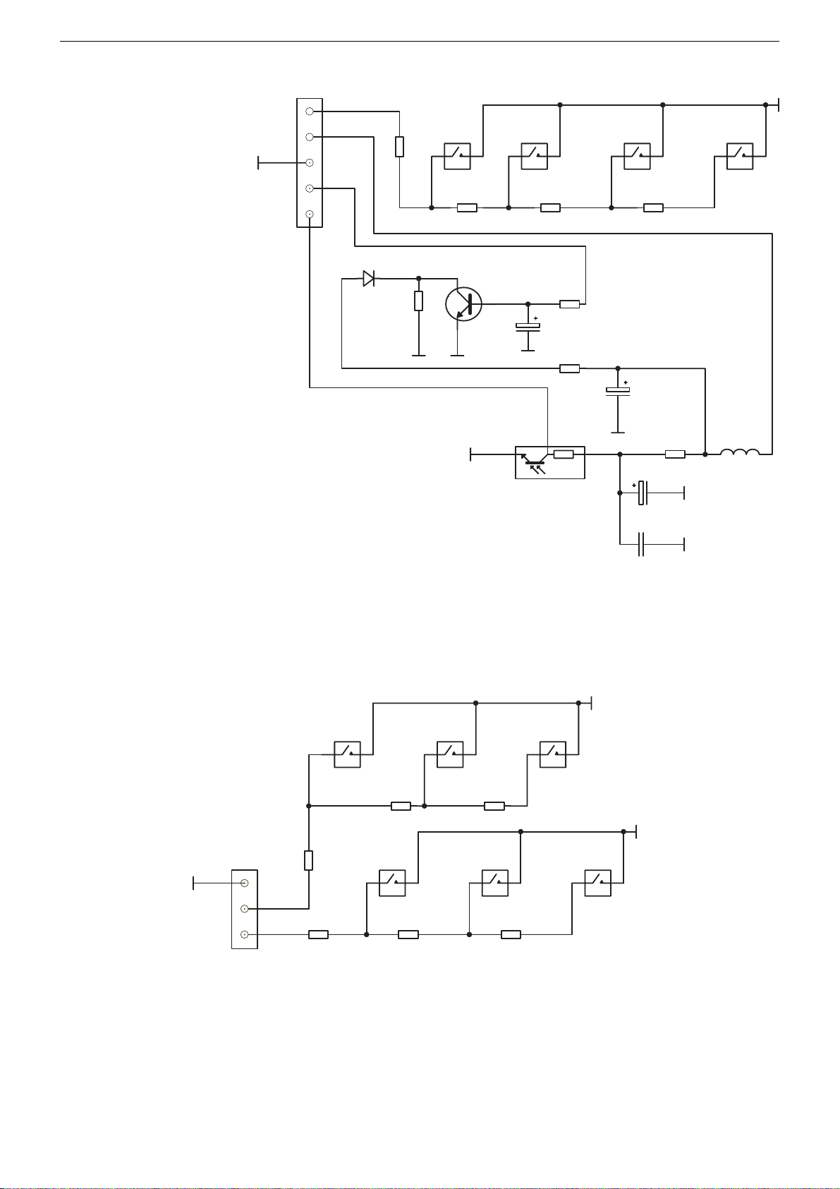
GRUNDIG Service Chassis D5
ZL5.191 - Bedienplatte / Keyboard
X402-1
5
4
3
2
1
LED1
D1
1K
R60
MENU
JUMPER
TACT
SWITCH
R61
R59
1K5
Q50
C102M
SWITCH
2
(+)
TACT
R58
1K8
R62
10K
C51
100U/16V
R63
100R
100U/16V
1
PA1
IR
C52
3
PR/VOL
TACT
SWITCH
R57
2K2
C54
*
C53
R64
JUMPER
(-)
TACT
SWITCH
L51
*
ZL5.195 - Bedienplatte / Keyboard
X402-2
3
2
1
CON3
REWIND
TACT
R53
JUM PER
R56
JUMPER
STOP
R52
1K5
EJECT
TACT SWITCH
R55
1K5
TACT
FORWARD
TV/DVD
TACT
R51
1K8
TACT SWITCH
SWITCH SWITCH SWITCH
R54
1K8
*
PLAY/PAUSE
TACT
SWITCH
2-Nov-2004
3 - 17
Page 25
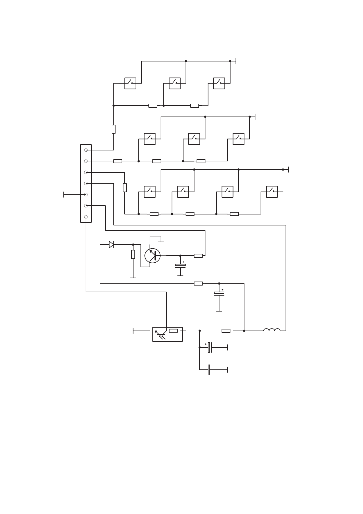
GRUNDIG Service Chassis D5
ZL6.191 - Bedienplatte / Keyboard
X402
CON7
R54
1K8
R62
10K
R63
100R
TV/DVD
TACT
SWITCH
PLAY/PAUSE
PR/VOL
TACT SWITCH
C52
100U/16V
TACT SWITCH
R57
2K2
(-)
TACT
SWITCH
STOPRE WIND
R55
1K5
R59
JUMPER
Q50
C102M
TACT
SWITCH
FORW ARD
(+)
TACT SWITCH
R51
1K8
TACT SWITCH
R58
1K8
C51
100U/16V
TACT
SWITCH
R53
JUMPER
7
6
5
4
3
2
1
R56
JUMPER
LED1
D1
R61
1K
EJECT
TACT SWITCH
MENU
R60
JUMPER
TACT
SWITCH
R52
1K5
1
2
PA1
IR
3
C54
*
C53
*
R64
JUMPER
2-Nov-2004
L51
*
3 - 18
 Loading...