

Grundig TVD37-2401, TVD55-2401 Schematic
TV Service Manual
1. Ergänzung / Supplement 1
Chassis D5
DVD Combo TV
Davio 14
TVD 37-2401 Text
GBC3200
Elegance 21 Flat
TVD 55-2401/5 Top
GBC3300
Zusätzlich erforderliche Unterlagen für den Komplettservice
Additionally required Service Documents for the Complete Service
Service
Manual
Sicherheit
Safety
Materialnr./Part No.
720108000001
Materialnummer/Part Number 720100488000
Änderungen vorbehalten/Subject to alteration • Printed in Germany …
H-S43 0105 • 8002/8012 oUKIRL, 8003/8013 oD, 8005/8015
http://www.grundig.com

GRUNDIG Service Chassis D5
Es gelten die Vorschriften und Sicherheitshinweise
gemäß dem Service Manual "Sicherheit", Materialnummer 720108000001, sowie zusätzlich die eventuell abweichenden, landesspezifischen Vorschriften!
Inhaltsverzeichnis
Seite
Allgemeiner Teil ................................. 1-2…1-14
Allgemeine Hinweise.................................................................... 1-2
Technische Daten ........................................................................ 1-3
Bedienhinweise ............................................................................ 1-5
Service- und Sonderfunktionen.................................................. 1-10
Sicherheits-Hinweis ................................................................... 1-11
IC Data Sheet & Specification (englisch) ................................... 1-12
Abgleich .........................................................2-1
Platinenabbildungen
und Schaltpläne ................................. 3-1…3-18
Block Diagram.............................................................................. 3-1
ZL6.190-03:
– Netzteil ..................................................................................... 3-2
– Ablenkung ................................................................................ 3-3
– NF-Endstufe ............................................................................. 3-4
– Leiterplatte ............................................................................... 3-5
ZL5.190-03
– Signalverarbeitung ................................................................... 3-6
– Leiterplatte ............................................................................... 3-9
ZL5.194 Bildrohrplatte................................................................ 3-13
ZL6.194 Bildrohrplatte................................................................ 3-14
ZL5.192-01 AV-Platte ................................................................ 3-15
ZL6.192-02 AV-Platte ................................................................ 3-16
ZL5.191 Bedienplatte................................................................. 3-17
ZL5.195 Bedienplatte................................................................. 3-17
ZL6.191 Bedienplatte................................................................. 3-18
The regulations and safety instructions shall be valid
as provided by the "Safety" Service Manual, part
number 720108000001, as well as the respective
national deviations.
Table of Contents
Page
General Section.................................. 1-2…1-14
General Notes .............................................................................. 1-2
Technical Data ............................................................................. 1-3
Operating Hints ............................................................................ 1-7
Service and Special Functions................................................... 1-10
Safety Advice ............................................................................. 1-11
IC Data Sheet & Specification.................................................... 1-12
Adjustment .................................................... 2-1
Layout of PCBs
and Circuit Diagrams ......................... 3-1…3-18
Block Diagram.............................................................................. 3-1
ZL6.190-03:
– Power Supply ........................................................................... 3-2
– Deflection ................................................................................. 3-3
– AF Amplifier.............................................................................. 3-4
– PCB.......................................................................................... 3-5
ZL5.190-03
– Signal Processing .................................................................... 3-6
– PCB.......................................................................................... 3-9
ZL5.194 CRT Board ................................................................... 3-13
ZL6.194 CRT Board ................................................................... 3-14
ZL5.192-01 AV Board ................................................................ 3-15
ZL6.192-02 AV Board ................................................................ 3-16
ZL5.191 Keyboard ..................................................................... 3-17
ZL5.195 Keyboard ..................................................................... 3-17
ZL6.191 Keyboard ..................................................................... 3-18
Explosionszeichnungen und
Ersatzteillisten...................................... 4-1…4-6
Explosionszeichnung Davio 14 .................................................... 4-1
Explosionszeichnung Elegance 21 .............................................. 4-2
Ersatzteillisten .............................................................................. 4-3
Allgemeiner Teil
Allgemeine Hinweise
Vor dem Öffnen des Gehäuses den Netzstecker ziehen!
Achtung: ESD-Vorschriften beachten
Leitungsverlegung
Bevor Sie die Leitungen und insbesondere die Masseleitungen lösen,
muss die Leitungsverlegung zu den einzelnen Baugruppen beachtet
werden.
Nach erfolgter Reparatur ist es notwendig, die Leitungsführung wieder
in den werkseitigen Zustand zu versetzen um evtl. spätere Ausfälle
oder Störungen zu vermeiden.
Durchführen von Messungen
Bei Messungen mit dem Oszilloskop an Halbleitern sollten Sie nur
Tastköpfe mit 10:1 - Teiler verwenden. Außerdem ist zu beachten,
dass nach vorheriger Messung mit AC-Kopplung der Koppelkondensator des Oszilloskops aufgeladen sein kann. Durch die Entladung
über das Messobjekt können Bauteile beschädigt werden.
Messwerte und Oszillogramme
Bei den in den Schaltplänen und Oszillogrammen angegebenen
Messwerten handelt es sich um Näherungswerte!
Exploded Views and
Spare Parts Lists.................................. 4-1…4-6
Exploded View Davio 14 .............................................................. 4-1
Exploded View Elegance 21 ........................................................ 4-2
Spare Parts Lists.......................................................................... 4-3
General Section
General Notes
Before opening the cabinet disconnect the mains plug!
Attention: Observe the ESD safety regulations
Wiring
Before disconnecting any leads and especially the earth connecting
leads observe the way they are routed to the individual assemblies.
On completion of the repairs the leads must be laid out as originally
fitted at the factory to avoid later failures or disturbances.
Carrying out Measurements
When making measurements on semi-conductors with an oscilloscope, ensure that the test probe is set to 10:1 dividing factor. If the
previous measurement was made on AC input, please note that the
coupling capacitor in the oscilloscope will be charged. Discharge via
the item being checked can damage the components.
Measured Values and Oscillograms
The measured values given in the circuit diagrams and oscillograms
are approximates!
1 - 2
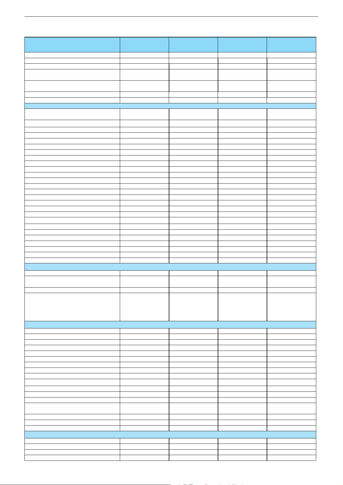
Technische Daten / Technical Data
Chassis D5GRUNDIG Service
Order Number
EAN
Colour
Destination
User manual languages
Sound
Remote Control
PICTURE
Size / Type
Real flat / Super flat
Deflection
100 Hz Picture-/32 kHz line frequency
Flicker free scanning (full frame memory)
Digital Color Transition Improv. (DCTI)
Digital Combfilter
Digital Luminace Transition Improv. (DLTI )
Picture Noise Reduction
SVM (Scan Velocity Moduladion)
Dynamic Focus
Preset picture modes
Tilt
Picture Formats
PIP (2 Tuner)
Multifold Tuner scan (Mosaic Picture)
PAT: Split screen (PICTURE + TEXT)
PAP: Double Window (PICTURE + PICTURE)
2
P
AT: Double window + TXT
POP: PICTURE on PICTURE
Picture freezing
Zoom with point function
Auto 16:9 selection via Scart
Automatic Color Standard Detection
Sharpness control
Blue Background
CHASSIS
TV-Chassis
Tuner
µ-Processor
Keyboard
ELECTRONIC
Stand by indicator
Manual & autom. labeling of prog.
Programable off timer
Programable on timer
Intelligent chanel search (Zapping funct.)
Program Edit
Intelligent Programme Switch
Auto switch off
Program memory TV/AV (opt.)
Teletext/Fasttext/Toptext
Teletext options
Teletext SWAP
Childlock
Menue languages OSD
SWAP (Recall function)
Service mode
Hotel mode
TUNING
Autom. Tuning System with country selection
Frequency Based Auto Search
Automatic Micro-search
Automatic Programing
Davio 14
TVD 37-2401 Text
UV2
GBC3200
40 13833-59703 2
procon silver
D, NL, DK, N, FIN, S,
E, P, ROW
D, GB, NL, DK, N, S,
FIN, E, P
MONO
Davio 14
TVD 37-2501 FR/Text
GBC5900
40 13833-59798 8
procon silver
F
F
MONO
RC 45 C / TP 165 C RC 45 C / TP 165 C
37 cm (14"), FST,
(4:3)
\
90°
\
\
\
\
\
\
\
\
\
\
\
\
\
\
\
\
\
\
\
[
[
[
\
37 cm (14"), FST,
(4:3)
\
90°
\
\
\
\
\
\
\
\
\
\
\
\
\
\
\
\
\
\
\
[
[
[
\
D5 (50 Hz) 90° D5 (50 Hz) 90°
PLL frequency
synthesizer tuning
Philips UOC OM836x
10 keys; TV/DVD,
menue, prog/vol,
plus, minus, eject,
play/pause, stop,
skip-fw, skip-bw
red LED
5 character
[
[
\
[
\
[
100/AV
1 page /
\ / \
\
\
[
7 languages:
D, GB, F, I, E, P, NL
[
[
PLL frequency
synthesizer tuning
Philips UOC OM836x
10 keys; TV/DVD,
menue, prog/vol,
plus, minus, eject,
play/pause, stop,
skip-fw, skip-bw
red LED
5 character
[
[
\
[
\
[
100/AV
1 page / \ / \
\
\
[
7 languages:
D, GB, F, I, E, P, NL
[
[
\\
[
\
[
\
[
\
[
\
Elegance 21
TVD 55-2401/5 Top
UV3
GBC3300
40 13833-59104 9
procon silver
D, I, NL, DK, N, FIN,
S, E, P, ROW
D, GB, I, NL, DK, N,
S, FIN, E, P
STEREO
Elegance 21
TVD 55-2501 FR/Top
GBC6000
40 13833-59799 5
procon silver
F
F
STEREO
RC 45 C / TP 165 C RC 45 C / TP 165 C
55 cm (21"), FST,
(4:3)
[
/ \
90°
\
\
\
\
\
\
\
\
\
\
\
\
\
\
\
\
\
\
\
[
[
[
\
55 cm (21"), FST,
(4:3)
[ / \
90°
\
\
\
\
\
\
\
\
\
\
\
\
\
\
\
\
\
\
\
[
[
[
\
D5 (50 Hz) 90° D5 (50 Hz) 90°
PLL frequency
synthesizer tuning
Philips UOC OM836x
10 keys; TV/DVD,
menue, prog/vol,
plus, minus, eject,
play/pause, stop,
skip-fw, skip-bw
red LED
5 character
[
[
\
[
\
[
100/AV
\ / \ / 7 pages
\
\
[
7 languages:
D, GB, F, I, E, P, NL
[
[
PLL frequency
synthesizer tuning
Philips UOC OM836x
10 keys; TV/DVD,
menue, prog/vol,
plus, minus, eject,
play/pause, stop,
skip-fw, skip-bw
red LED
5 character
[
[
\
[
\
[
100/AV
\ / \ / 7 pages
\
\
[
7 languages:
D, GB, F, I, E, P, NL
[
[
\\
[
\
[
\
[
\
[
\
1 - 3
Chassis D5GRUNDIG Service
Manual fine tuning
Direct chanal selection
PAL/BG
SECAM/L´/L
NTSC-Playback via Scart (3,58/4,43)
Cable TV / Hyperband (S1-S41)
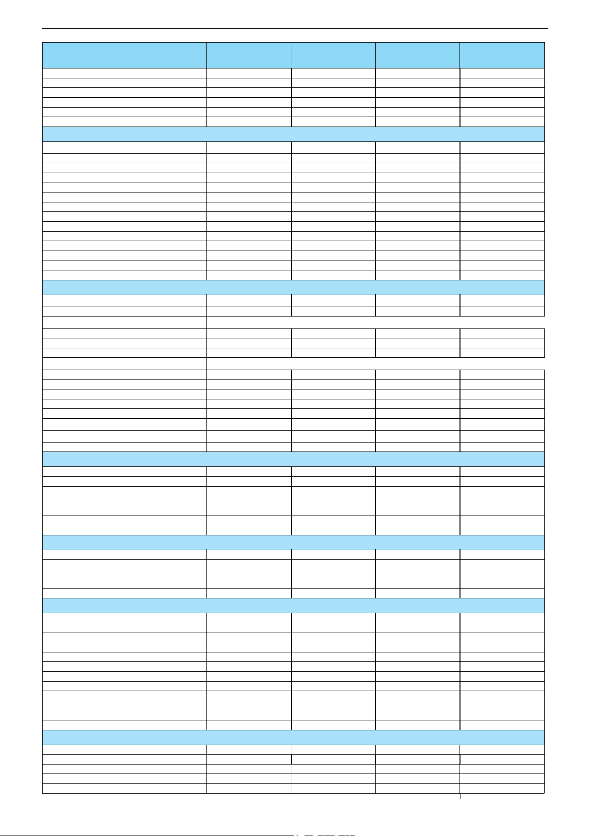
AUDIO
Mono/Stereo/Nicam
AV Stereo
Virtual Dolby
Subwoofer
Dynamic Bass
DSP (Digital Sound Processor)
Balance Adjustment
AVL (Audio Volume Level)
PIP listening via Headphone jack
Equalizer
Space Sound Effect
Audio mode
Audio amplifier without extern LS
Tweeter (2 way speaker system)
DVD
4:3 / 16:9 / letterbox format
Dolby Digital
Disc formats:
DVD R/RW (+/-)
CD-R
CD-RW
Media formats:
DVD-Video
VCD
SVC
CD-Audio
CD-ROM
Freeze / Zoom
Coaxial / Optical audio out
Region Code
POWER SUPPLY / CABINET
Power voltage
Power switch
Power consumption
Cabinet (WxHxD, cm) / Weight
FRONT PANEL CONNECTIONS
Headphones
Cinch-AV socket
S-Video
REAR PANEL CONNECTIONS
Euro-AV-Socket AV1
Euro-AV Socket AV2
Euro-AV Socket AV3
S-Video
Digital Audio out
Audio out
Antenna for terrestial reception
Power supply plug
SUPPLIED ACCESSORIES
Remote control (incl. battery)
Power cord
Telescopic antenna
Instruction manual
Warranty info
Davio 14
TVD 37-2401 Text
UV2
[
[
[
\
[
[
[
/ \ / \[ / \ / \
[
\
\
\
\
\
[
\
\
\
\
2 x 5 W (RMS)
\\
[
[
[[
[
[
[[
[
[
[
JPEG, MP3 playback[JPEG, MP3 playback
[
/ [
[ / \
Factory setting: RC 2 Factory setting: RC 2
230V~, 50/60 Hz
[
55 W, standby 2 W in
accordance to
IEC 62087-2002
39,1 x 39,5 x 38,2 cm
approx. 12,3 kg
[ , position lateral [ , position lateral
3 x Cinch - Video in,
Audio L/R in
(position lateral)
\
CVBS in-/output,
RGB input
\
\
\
Yes, coaxial
\
1 x Coaxial-socket for
TV-tuner-in, according
to DIN 45325
\\
[
\ / fix mounted
[
[
[[
Davio 14
TVD 37-2501 FR/Text
[
[
[
[
[
[
[
\
\
\
\
\
[
\
\
\
\
2 x 5 W (RMS)
[
[
[
[
[
[
[ / [
[ / \
230V~, 50/60 Hz
[
55 W, standby 2 W in
accordance to
IEC 62087-2002
39,1 x 39,5 x 38,2 cm
approx. 12,3 kg
3 x Cinch - Video in,
Audio L/R in
(position lateral)
\
CVBS in-/output,
RGB input
\
\
\
Yes, coaxial
\
1 x Coaxial-socket for
TV-tuner-in, according
to DIN 45325
[
\ / fix mounted
[
[
Elegance 21
TVD 55-2401/5 Top
UV3
[
[
[
\
[
[
[
/ [ / [[ / [ / [
[
\
\
\
\
\
[
\
\
\
\
2 x 8 W (RMS)
\\
[
/ [ / [
[
[[
[
[
[[
[
[
[
JPEG, MP3 playback[JPEG, MP3 playback
/ [
[
[ / \
Factory setting: RC 2 Factory setting: RC 2
230V~, 50/60 Hz
[
73 W, standby 2 W in
accordance to
IEC 62087-2002
61,1 x 46,4 x 52,6 cm
approx. 24,6 kg
[ , position lateral [ , position lateral
3 x Cinch - Video in,
Audio L/R in
(position lateral)
\
CVBS in-/output,
RGB input
CVBS in-/output,
S-Video input
\
\
Yes, coaxial
\
1 x Coaxial-socket for
TV-tuner-in, according
to DIN 45325
\\
[
\ / fix mounted
\
[
[[
Elegance 21
TVD 55-2501 FR/Top
[
[
[
[
[
[
[
\
\
\
\
\
[
\
\
\
\
2 x 8 W (RMS)
[ / [ / [
[
[
[
[
[
[ / [
[ / \
230V~, 50/60 Hz
[
73 W, standby 2 W in
accordance to
IEC 62087-2002
61,1 x 46,4 x 52,6 cm
approx. 24,6 kg
3 x Cinch - Video in,
Audio L/R in
(position lateral)
\
CVBS in-/output,
RGB input
CVBS in-/output,
S-Video input
\
\
Yes, coaxial
\
1 x Coaxial-socket for
TV-tuner-in, according
to DIN 45325
[
\ / fix mounted
\
[
1 - 4
Chassis D5GRUNDIG Service
(
)
g
g
g
g
g
g
g
g
g
g
g
g
g
g
y
g
g
p
p
p
p
g
g
gung
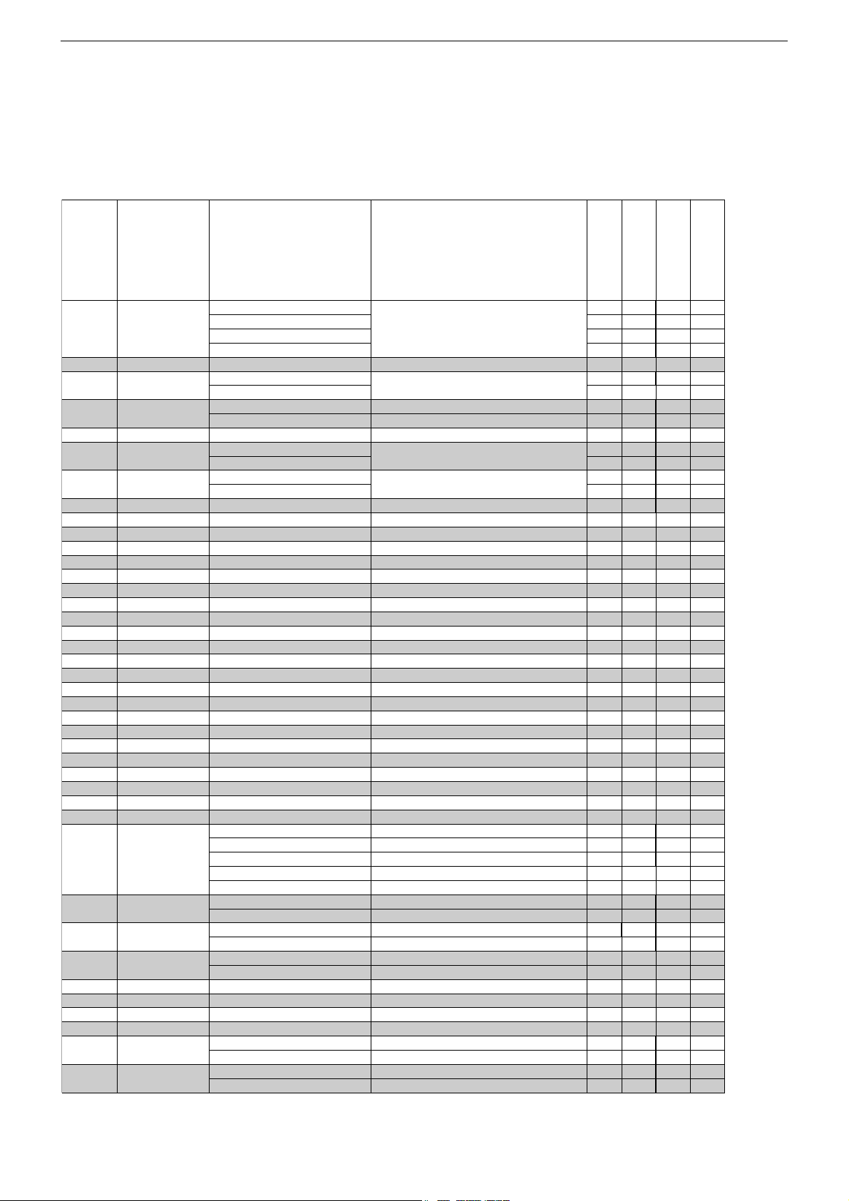
Service- und Sonderfunktionen
Service Mode aktivieren: Taste " i " (Hauptmenü) drücken –> Ser-
vice Code "8500" eingeben.
Service Mode beenden: Taste "TXT" drücken.
1. Grundeinstellwerte
Folgende Tabelle zeigt alle typenbezogenen Grundeinstellungen im
Service Mode. Alle mit * gekennzeichneten Werte müssen zusätzlich nach Abgleich (Seite 2-1) eingestellen werden.
SERVICE
P+/P–
0
1
2
3
4
5
6
7
8
9
10
11
12
13
14
15
16
17
18
19
20
21
22
23
24
25
26
27
28
29
30
31
32
33
34
35
36
37
38
39
Menüpunkt
Point of Menu
P+/P–
TUNER
AGC
STD
EEPE
PEAK
HEAD
SCRN
GRN
RED
BLUE
BLOG
BLOR
YDLY
SAT
HUE
CON
CDR
BRI
EWT
EWCU
EWCL
EWPW
HSHT
EWW
VAMP
SCOR
VSHT
VSLP
RGB
VZOM
SSTD
STYP
TOPTEXT
TXT table
PWLT
IFOF
HPAR
HBOW
HOTEL
SUBWOOFER
PANASONIC
PHILIPS
SHARP
TEMIC
siehe Abgleich / see Adjustment
STD-BY On
STD-BY Off
00
01
siehe Ab
YES
NO
ON
OFF
siehe Abgleich / see Adjustment
siehe Ab
siehe Abgleich / see Adjustment
siehe Ab
siehe Abgleich / see Adjustment
siehe Abgleich / see Adjustment
siehe Abgleich / see Adjustment
siehe Ab
siehe Abgleich / see Adjustment
siehe Ab
siehe Abgleich / see Adjustment
siehe Ab
siehe Abgleich / see Adjustment
siehe Ab
siehe Abgleich / see Adjustment
siehe Ab
siehe Abgleich / see Adjustment
BG-ONLY
I-ONLY
BG + DK
BG + LL'
ALL SYS.
NICAM On
NICAM Off
YES
NO
WEST
EAST
siehe Abgleich / see Adjustment
siehe Ab
ON
OFF
YES
NO
Einstellung
Adjustment
/
Thomson
leich / see Adjustment
leich / see Adjustment
leich / see Adjustment
leich / see Adjustment
leich / see Adjustment
leich / see Adjustment
leich / see Adjustment
leich / see Adjustment
leich / see Adjustment
eingebauten Tuner wählen
select used tuner
Netzschalter-Ein –> Standby
power switch ON –> standby
EEPROM-Reset
Bildschärfe / Peakin
Kopfhörer / Headphone
benötigt für Schirmgitter-Abgleich
used for screen adjustment
Grün-Pe
Rot-Pe
Blau-Pe
Grün / Green cut off
Rot / Red cut off
Luminanz-Verzö
Farbsättigung / Saturation
Bildschärfe / Sharpness
Kontrast / Contast
Kathode-Pe
Helli
Ost/West Tra
Ecken oben / Upper corner
Ecken unten / Lower corner
Ost/West Parabel 4:3 / East west parabola width 4:3
Bild
Bildbreite / Horizontal width
Bildhöhe / Vertical am
S-Korrektur / S correction
Bild
Bildmitte / Vertical slope
OSD Helli
Vertikal Zoom / Vertical zoom
Strahlstrombegrenzung / Peak white limitin
Offset ZF-Demodulator / Offset IF demodulator
Schräglage vertikal / Horizontal parallelogram
Horizontale Bie
Service and Special Functions
Start of the Service Mode: Press button " i " (Main Menu) –> Enter
Service Code "8500".
End the Service Mode: Press button "TXT".
1. Basic Settings
The following table shows all type specific basic settings in the service mode. In addition all values marked with * must be adjusted
according to adjustment (page 2-1).
Hinweis
Hint
el / Green level
el / Red level
el / Blue level
erung / Luminance dela
el / Cathode drive level
keit / Brightness
ez / East West Trapezium
osition horizontal / Horizontal shift
litude
osition vertikal / Vertical shift
keit / Brightness
/ Horizontal bow
DAVIO 14
TVD 37-2401 Text
DAVIO 14
TVD 37-2501 FR/Text
ELEGANCE 21 Flat
TVD 55-2401/ 5 Top
35 35 35
XXX
X
X
32
X
X
32*
30*
30*
30*
36*
14
20
32
32
02
32
28*
32*
32*
17*
32*
60*
35*
25*
28*
34*
01
35*
X
X
X
X
09
32
32*
32*
X
XXX
X
32 32
XX
XX
32*
32*
30*
30*
30*
30*
30*
30*
36*1436*
14
203220
32
320232
02
32
28*3228*
32*
32*
32*
32*
17*
17*
32*
32*
60*
60*
35*
35*
25*
25*
28*
28*
34*0134*
01
35* 35*
X
X
X
X
XX
X
X
093209
32
32*
32*
32*
32*
XX
ELEGANCE 21 Flat
TVD 55-2501 FR/ Top
35
X
X
32
X
X
32*
30*
30*
30*
36*
14
20
32
32
02
32
28*
32*
32*
17*
32*
60*
35*
25*
28*
34*
01
35*
X
X
X
X
09
32
32*
32*
X
X
* Mittelwert / Average Value
1 - 9
Chassis D5GRUNDIG Service
y
Ä
SERVICE
P+/P–
40
41
42
43
44
45
46
47
48
49
50
51
52
Menüpunkt
Point of Menu
P+/P–
CRT
TEST
AAV
PAL
EWP1
DBAS
VOL
SCART 2
F-AV
F-SVHS
AV ST CURVE
NTSC
OPENNING
Einstellung
Adjustment
/
4:3
16:9
siehe Abgleich / see Adjustment
YES
NO
YES
NO
siehe Abgleich / see Adjustment
YES
NO
siehe Abgleich / see Adjustment
ON
OFF
ON
OFF
ON
OFF
HIGH
LOW
YES
NO
YES
NO
Hinweis
Hint
automatische AV -Umschaltung
automatic AV switching
nur PAL / PAL onl
andere Versionen / other versions
16:9 Ost/West Parabel (für 4:3 Geräte)
16:9 East west parabola width (for 4:3 sets)
Dynamik-Bass / Dynamic bass
Volume Pegel
Volume level
SCART - 2
Front - AV
Front - SVHS
ndert Linearität bei Lautstärke +/Changes linearity of volume +/NTSC Wiedergabe
NTSC Playback
DAVIO 14
TVD 37-2401 Text
DAVIO 14
TVD 37-2501 FR/Text
ELEGANCE 21 Flat
TVD 55-2401/ 5 Top
ELEGANCE 21 Flat
TVD 55-2501 FR/ Top
XXX
35*X35*
35*
X
X
X
08*
08* 08*
X
XX
50
50 50
X
X
XX
X
XXXXX
XXX
XXXX
X
35*
X
X
X
X
08*
X
50
X
X
X
X
X
X
X
* Mittelwert / Average Value
2. Programmsuchlauf (ATS)
Tasten " i " (Hauptmenü) –>P+ /
P+ / P–
"PROGRAMMSUCHLAUF" –> "OK"–>P+ /
P–
"SUCHLAUF" –> "OK"–>
P–
/ / Land
auswählen und mit "OK" Suchlauf starten.
Das automatische Sendersuchsystem stoppt bei jedem empfangswürdigen Sender (AFC und Koinzidenz) und speichert automatisch
die entsprechenden Senderdaten mit dem jeweiligen Standard. Danach wird der Suchlauf fortgesetzt.
Tastendruck "
i " bricht den ATS-Lauf ab.
3. Software-Versionsnummer
Die Software-Versionsnummer wird nach Beenden des Service Modes angezeigt:
VER SD5965_G02
OF96
T01031711
Sicherheits-Hinweis
Die in den Fernsehgeräten auftretende Röntgenstrahlung entspricht
den Bestimmungen der Physikalisch-Technischen Bundesanstalt
vom 8. Januar 1987.
Die Hochspannung für die Bildröhre und die damit auftretende
Röntgenstrahlung ist abhängig von der exakten Einstellung der
Netzteilspannung +B.
Nach jeder Reparatur im Netzteil oder in der Horizontalablenkung
ist die Hochspannung zu messen und gegebenenfalls einzustellen.
Schutzschaltungen im Gerät dürfen nur kurzzeitig außer Betrieb gesetzt werden, um Folgeschäden am Chassis oder an der Bildröhre
zu vermeiden.
Beim Austausch der Bildröhre dürfen nur die in den Ersatzteillisten
vorgeschriebenen Typen verwendet werden.
2. Autoprogram (ATS)
Buttons " i " (Main menu) –>P+ /
"AUTOPROGRAM" –> "OK"–>P+ /
P–
"SETUP" –> "OK"–>P+ /
P–
/ / select Country and
P–
start search with "OK".
The autoprogram system stops at every station of acceptable reception quality (AFC and coincidence) and stores the station data
and the respective standard automatically. The system then continues searching.
Pressing the "
i " button stops the ATS function.
3. Software Version Number
The software version number is shown after ending the service
mode:
VER SD5965_G02
OF96
T01031711
Safety Advice
The X-radiation developing in the sets conforms to the X-radiation
Regulations (January 8, 1987), issued by the Physikalisch-Technische Bundesanstalt (federal physiotechnical institution).
The high tension for the picture tube and thus the developing X-radiation depends on the precise adjustment of the +B power supply.
After every repair of the power supply unit or the horizontal deflection stage it is imperative that the EHT for the picture tube is
checked and re-adjusted if necessary.
To avoid consequential damages to the chassis or the picture tube
the integrated protective circuits are allowed to be put out of operation only for a short time.
When replacing the picture tube use only the types specified in the
spare parts lists.
1 - 10

Chassis D5GRUNDIG Service
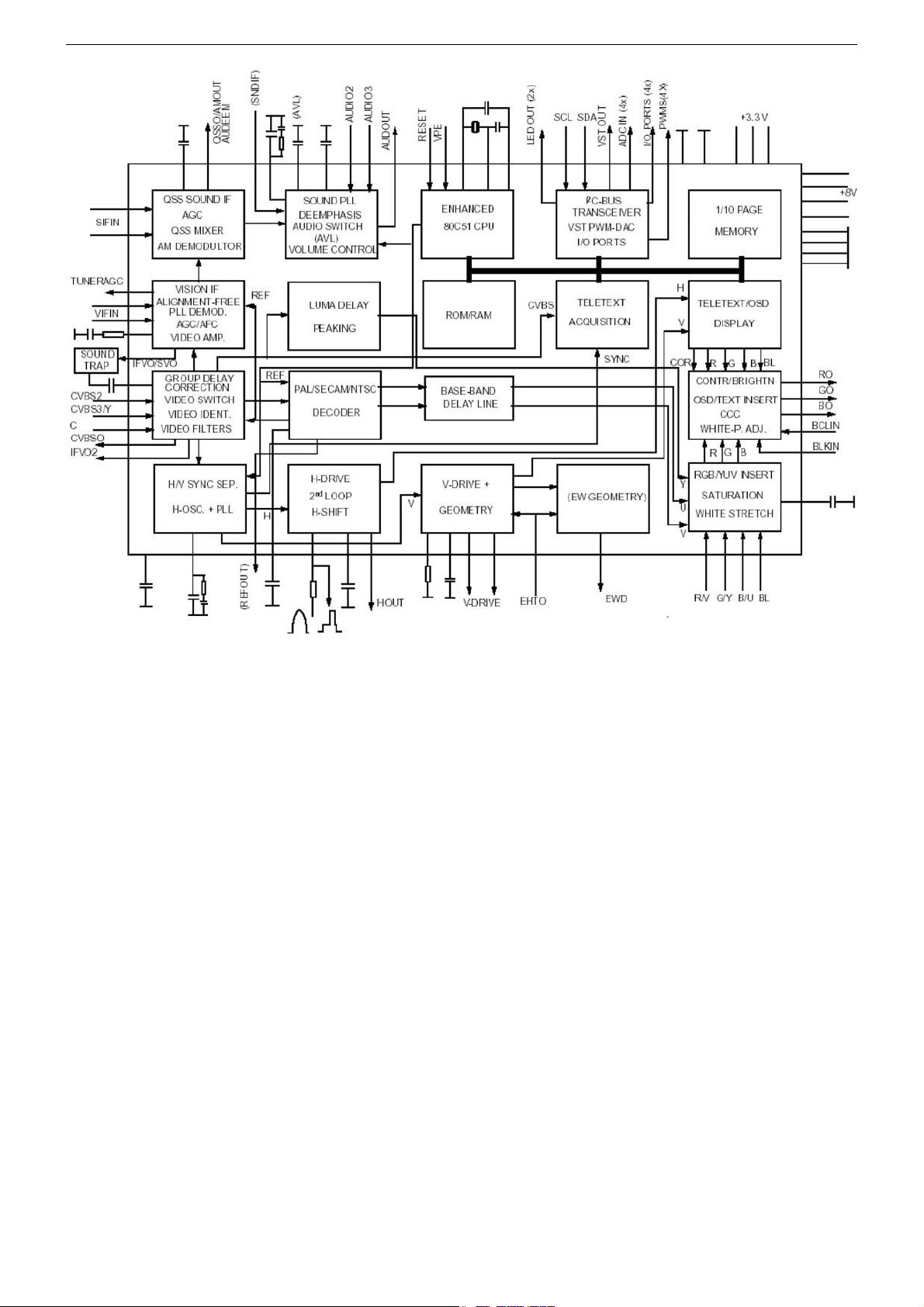
IC Data Sheets & Specifications
IC 101 - OM 8365
The OM8365H combine the functions of a video processor together
with a µ-Controller, US Closed Caption decoder and Teletext decoder. The Teletext decoder has an internal RAM memory for 10 page
text. The ICs are intended to be used in economy television receivers with 110° picture tubes. The ICs have supply voltages of 8V
and 3.3V and they are mounted in a QFP 80 envelope.
TV-Signal Processor
• Multi-standard vision IF circuit with alignment-free PLL demodula-
tor.
• Internal (switchable) time-constant for the IF-AGC circuit.
• The QSS and mono FM functionality are both available so that an
FM/AM TV receiver can be built without the use of additional ICs
• The mono intercarrier sound circuit has a selective FM-PLL de-
modulator which can be switched to the different FM sound frequencies (4.5/5.5/6.0/6.5MHz). The quality of this system is such
that the external band-pass filters can be omitted.
• The FM-PLL demodulator can be set to centre frequencies of
4.74/5.74MHz so that a second sound channel can be demodulated. In such an application it is necessary that an external bandpass filter is inserted.
• The vision IF and mono intercarrier sound circuit can be used for
the demodulation of FM radio signals.
• Video switch with 2 external CVBS inputs and a CVBS output.
One of the CVBS inputs can be used as Y/C input.
• 2 external audio inputs. The selection of the various inputs is cou-
pled to the selection of the CVBS signals.
• Integrated chrominance trap circuit.
• Integrated luminance delay line with adjustable delay time.
• Picture improvement features with peaking (with switchable cen-
tre frequency, depeaking, variable positive/negative overshoot ratio and video dependent coring) and white stretching.
• Switchable group delay correction in the CVBS path.
• Integrated chroma band-pass filter with switchable centre fre-
quency.
• Switchable DC transfer ratio for the luminance signal.
• Only one reference (12MHz) crystal required for the µ-Controller,
Teletext- and the colour decoder.
• Multi-standard colour decoder with automatic search system.
• Internal base-band delay line.
• Indication of the Signal-to-Noise ratio of the incoming CVBS si-
gnal.
• A linear RGB/YUV/YPBPR input with fast blanking for external
RGB/YUV sources. The synchronisation circuitcan be connected
to the incoming Y signal. The Text/OSD signals are internally
supplied from the µ-Controller / Teletext decoder.
• RGB control circuit with ‘Continuous Cathode Calibration’, white
point and black level off-set adjustment so that the colour temperature of the dark and the light parts of the screen can be chosen
independently.
• Contrast reduction possibility during mixed-mode of OSD and
Text signals.
• Adjustable ‘wide blanking’ of the RGB outputs.
• Horizontal synchronization with two control loops and alignment-
free horizontal oscillator.
• Vertical count-down circuit.
• Vertical driver optimized for DC-coupled vertical output stages.
• Horizontal and vertical geometry processing.
• Horizontal and vertical zoom function for 16:9 applications.
• Horizontal parallelogram and bow correction for large screen pic-
ture tubes.
• Low-power start-up of the horizontal drive circuit.
µ-Controller
• 80C51 µ-controller core standard instruction set and timing.
• 1 µs machine cycle.
• 64 - 96Kx8-bit late programmed ROM.
• 12Kx8-bit DataRAM (shared between Display, Acquisition and
Auxiliary RAM).
• Interrupt controller for individual enable/disable with two level
priority.
• Two 16-bit Timer/Counter registers.
• One 16-bit Timer with 8-bit Pre-scaler.
• WatchDog timer.
• Auxiliary RAM page pointer.
• 16-bit Data pointer.
• Stand-by, Idle and Power Down modes.
• 14 bits PWM for Voltage Synthesis Tuning.
• 8-bit A/D converter with 4 multiplexed inputs.
• 5 PWM (6-bits) outputs for control of TV analogue signals.
• 18 general I/O ports.
Data Capture
• Text memory for 10 pages.
• Inventory of transmitted Teletext pages stored in the Transmitted
Page Table (TPT) and Subtitle Page Table (SPT).
• Data Capture for US Closed Caption.
• Data Capture for 525/625 line WST, VPS (PDC system A) and
Wide Screen Signalling (WSS) bit decoding.
• Automatic selection between 525 WST/625 WST.
• Automatic selection between 625 WST/VPS on line 16 of VBI.
• Real-time capture and decoding for WST Teletext in Hardware, to
enable optimized µ-processor throughput.
• Automatic detection of FASTEXT transmission.
• Real-time packet 26 engine in Hardware for processing accented, G2 and G3 characters.
• Signal quality detector for video and WST/VPS data types.
• Comprehensive teletext language coverage.
• Full Field and Vertical Blanking Interval (VBI) data capture of
WST data Display.
• Teletext and Enhanced OSD modes.
• Features of level 1.5 WST and US Close Caption.
• Serial and Parallel Display Attributes.
• Single/Double/Quadruple Width and Height for characters.
• Scrolling of display region.
• Variable flash rate controlled by software.
• Enhanced display features including overlining, underlining and
italics.
• Soft colours using CLUT with 4096 colour palette.
• Globally selectable scan lines per row (9/10/13/16) and character
matrix [12x10, 12x13, 12x16 (VxH)].
• Fringing (Shadow) selectable from N-S-E-W direction.
• Fringe colour selectable.
• Meshing of defined area.
• Contrast reduction of defined area.
• Cursor.
• Special Graphics Characters with two planes, allowing four colours per character.
• 32 software redefinable On-Screen display characters.
• 4 WST Character sets (G0/G2) in single device (e.g. Latin, Cyrillic, Greek, Arabic).
• G1 Mosaic graphics, Limited G3 Line drawing characters.
• WST Character sets and Closed Caption Character set in single
device.
1 - 11
Chassis D5GRUNDIG Service
MSP 34x0G Multistandard Sound Processor Family
The MSP 3410G family of single-chip Multistandard Sound Processors covers the sound processing of all analog TV-Standards
worldwide, as well as the NICAM digital sound standards. The full
TV sound processing, starting with analog sound IF signal-in, down
to processed analog AF-out, is performed on a single chip. This
new generation of TV sound processing ICs now includes versions
for processing the multichannel television sound (MTS) signal conforming to the standard recommended by the Broadcast Television
Systems Committee (BTSC). The DBX noise reduction, or alternatively, Micronas Noise Reduction (MNR) is performed.
Other processed standards are the Japanese FM-FM multiplex
standard (EIA-J) and the FM Stereo Radio standard.
The MSP 3410G has optimum stereo performance without any adjustments.
The MSP 3410G has built-in automatic functions:
The IC is able to detect the actual sound standard automatically
(Automatic Standard Detection). Furthermore, pilot levels and identification signals can be evaluated internally with subsequent switching between mono/ stereo/bilingual; no I2C interaction is necessary (Automatic Sound Selection).
The MSP 3410G can handle very high FM deviations even in conjunction with NICAM processing.
TDA7266S 5+5w Dual Bridge Amplifier
The TDA7266S is a dual bridge amplifier specially designed for TV
and Portable Radio applications.
• Wide supply voltage range (3-18V)
• Minimum external components
– no swr capacitor
– no bootstrap
– no boucherot cells
– internally fıxed gaın
• Stand-by & mute functıons
• Short cırcuıt protection
• Thermal overload protection
TDA 7442 Digitally Controlled Audio Processor
The TDA7442/42D is volume tone (bass and treble) balance (Left/
Right) processors for quality audio applications in TV and Hi-Fi systems. It reproduces surround sound by using a programmable
phase shifter. Control of all the functions is accomplished by serial
bus. The AC signal setting is obtained by resistor networks and
switches combined with operational amplifiers. Thanks to the BIPOLAR/CMOS Technology used, Low Distortion, Low Noise and DC
stepping are obtained.
• 4 stereo inputs
• Input attenuation control in 0.5dB step
• Treble and bass control
• Two surround mode available with 4 selectable responses:
- music
- simulated stereo
• Two speaker attenuators:
- 2 independent speaker controls
• In 1dB steps for balance facility
- independent mute function
• All functions programmable via serial Bus
• 2 monitor output (only for TDA7442)
CXA 2040AQ I2C Bus-Compatible Video Switch
The CXA2040AQ is an I2C bus-compatible 5-input, 3-output video
switch for TVs.
Features
• Serial data control via I2C bus
• 5 composite video input systems
• 2 Y/C (S terminal) input systems
• 3 composite video output systems
• 1 Y/C (S terminal) output system
• Input can be selected independently for each output system.
• SYNC_ID function for CV1 system input
• Built-in 6dB amplifier for CVOUT2 system output
• Built-in Y/C MIX circuit
• Slave address can be changed (90H/92H).
• High impedance maintained by I2C bus line (SDA, SCL) even
when power is OFF.
1 - 12
 Loading...