

Grundig THARUS 51 LCD 51-9410 Schematic
TV Service Manual
THARUS 51
LCD 51-9410 DOLBY
GBB3700
Zusätzlich erforderliche Unterlagen für den Komplettservice
Additionally required Service Documents for the Complete Service
Service
Manual
Sicherheit
Safety
Materialnr./Part No.
720108000001

GRUNDIG Service THARUS 51 LCD 51-9410 DOLBY
Es gelten die Vorschriften und Sicherheitshinweise
gemäß dem Service Manual "Sicherheit", Materialnummer 720108000001, sowie zusätzlich die eventuell abweichenden, landesspezifischen Vorschriften!
Inhaltsverzeichnis
Seite
Allgemeiner Teil ................................. 1-3…1-14
Messgeräte .................................................................................. 1-3
Allgemeine Hinweise.................................................................... 1-3
Technische Daten ........................................................................ 1-4
Bedienhinweise ............................................................................ 1-5
Service- und Sonderfunktionen .................................................... 1-9
Servicehinweise ......................................................................... 1-13
Abgleich ......................................................... 2-1
Platinenabbildungen
und Schaltpläne ................................. 3-1…3-42
Oszillogramme ............................................................................. 3-1
Chassisplatte / NF-Platte ............................................................. 3-2
– Teil 1 ...................................................................................... 3-14
– Teil 2 ...................................................................................... 3-18
– Teil 3 ...................................................................................... 3-22
– NF-Platte ................................................................................ 3-21
Adapter-Sound-Platte ................................................................ 3-26
IR/BA-Platte ............................................................................... 3-26
Falconic-Platte ........................................................................... 3-27
– Teil 1 ...................................................................................... 3-30
– Teil 2 ...................................................................................... 3-33
M2-Platte .................................................................................... 3-37
The regulations and safety instructions shall be
valid as provided by the "Safety" Service Manual,
part number 720108000001, as well as the
respective national deviations.
Table of Contents
Page
General Section .................................. 1-3…1-14
Test Equipment ............................................................................ 1-3
General Notes .............................................................................. 1-3
Technical Data ............................................................................. 1-4
Operating Hints ............................................................................ 1-7
Service and Special Functions................................................... 1-11
Service Instructions .................................................................... 1-13
Alignment.......................................................2-2
Layout of the PCBs
and Circuit Diagrams ......................... 3-1…3-42
Oscillograms ................................................................................ 3-1
Chassis Board / AF Board ........................................................... 3-2
– Part 1 ...................................................................................... 3-14
– Part 2 ...................................................................................... 3-18
– Part 3 ...................................................................................... 3-22
– AF Board ................................................................................ 3-21
Adapter Sound Board ................................................................ 3-26
IR/BA Board ............................................................................... 3-26
Falconic Board ........................................................................... 3-27
– Part 1 ...................................................................................... 3-30
– Part 2 ...................................................................................... 3-33
M2 Board ................................................................................... 3-37
Ersatzteillisten ...................................... 4-1…4-3
Spare Parts Lists .................................. 4-1…4-3
1 - 2

GRUNDIG Service THARUS 51 LCD 51-9410 DOLBY
Allgemeiner Teil
Messgeräte
100MHz-Oszilloskop mit Tastkopf 10:1
Digitalvoltmeter
Farbbildgenerator
Allgemeine Hinweise
Achtung: ESD-Vorschriften beachten
Vor dem Öffnen des Gehäuses zuerst den Netzstecker ziehen!
Leitungsverlegung
Bevor Sie die Leitungen und insbesondere die Masseleitungen lösen,
muss die Leitungsverlegung zu den einzelnen Baugruppen beachtet
werden.
Nach erfolgter Reparatur ist es notwendig, die Leitungsführung wieder
in den werkseitigen Zustand zu versetzen um evtl. spätere Ausfälle
oder Störungen zu vermeiden.
Durchführen von Messungen
Bei Messungen mit dem Oszilloskop an Halbleitern sollten Sie nur
Tastköpfe mit 10:1 - Teiler verwenden. Außerdem ist zu beachten,
dass nach vorheriger Messung mit AC-Kopplung der Koppelkondensator des Oszilloskops aufgeladen sein kann. Durch die Entladung
über das Messobjekt können Bauteile beschädigt werden.
Messwerte und Oszillogramme
Bei den in den Schaltplänen und Oszillogrammen angegebenen
Messwerten handelt es sich um Näherungswerte!
DOLBY-Hinweis
DOLBY und das Doppel-D-Symbol ij sind Warenzeichen der Dolby
Laboratories Licensing Corporation.
General Section
Test Equipment
100MHz oscilloscope with 10:1 test probe
Digital voltmeter
Colour video generator
General Notes
Attention: Observe the ESD safety regulations
Before opening the cabinet disconnect the mains plug!
Wiring
Before disconnecting any leads and especially the earth connecting
leads observe the way they are routed to the individual assemblies.
On completion of the repairs the leads must be laid out as originally
fitted at the factory to avoid later failures or disturbances.
Carrying out Measurements
When making measurements on semi-conductors with an oscilloscope, ensure that the test probe is set to 10:1 dividing factor. If the
previous measurement was made on AC input, please note that the
coupling capacitor in the oscilloscope will be charged. Discharge via
the item being checked can damage the components.
Measured Values and Oscillograms
The measured values given in the circuit diagrams and oscillograms
are approximates!
DOLBY Hint
DOLBY and the double-D symbol ij are trademarks of Dolby
Laboratories Licensing Corporation.
1 - 3
GRUNDIG Service THARUS 51 LCD 51-9410 DOLBY
Technische Daten / Technical Data
THARUS 51
LCD 51-9410 DOLBY
(VNM)
Bildröhre / Picture Tube
Sichtbares Bild
Visible picture
Bildschirmdiagonale
Screen diagonal
Maximale Auflösung
Resolution max.
Hintergrundbeleuchtung
Back light
Kontrastverhältnis
Contrast ratio
Leuchtdichte
Brightness
Betrachtungswinkel
Viewing angel
Display-Trägheit
Response time
Back light
Programmspeicherplätze
Programme positions
TV Guide ja / yes
Easy dialog ja / yes
Tuner
TV-Normen
TV-Standards
Stereo Systeme
Stereo systems
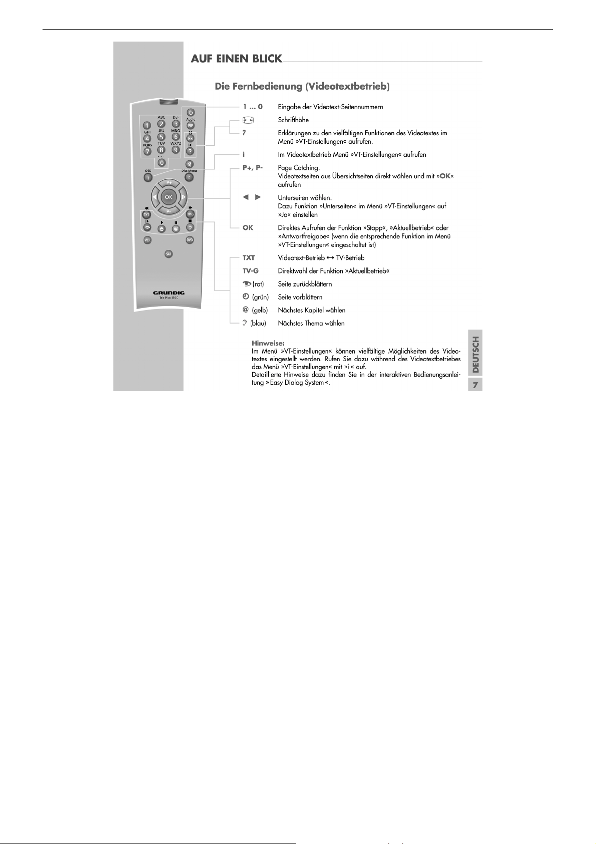
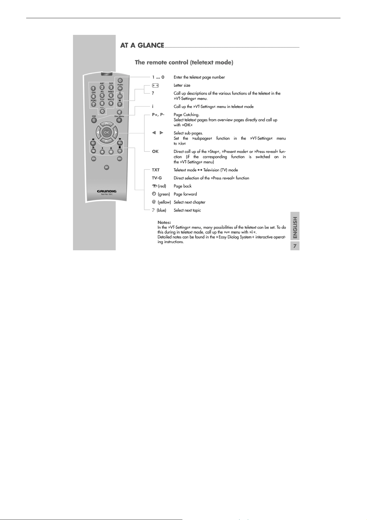
Videotext
Teletext
Musikleistung ohne externe LS
Music power without external LS
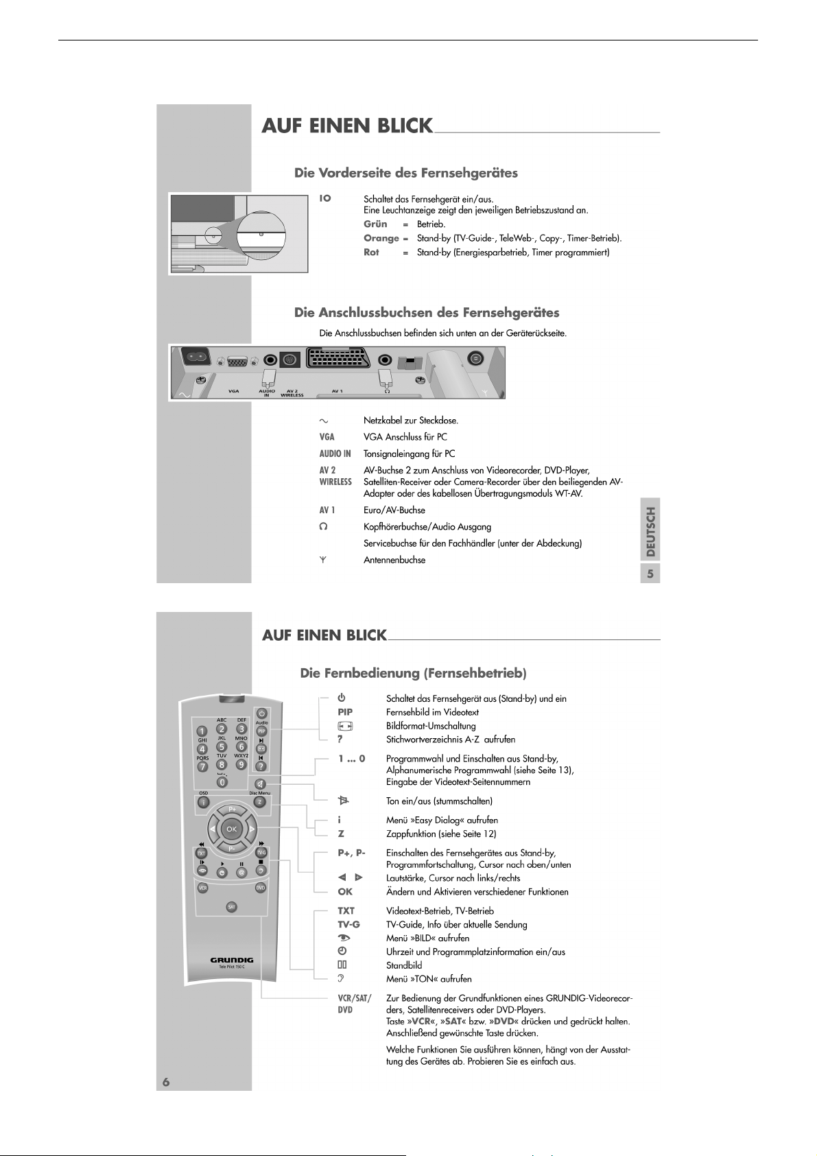
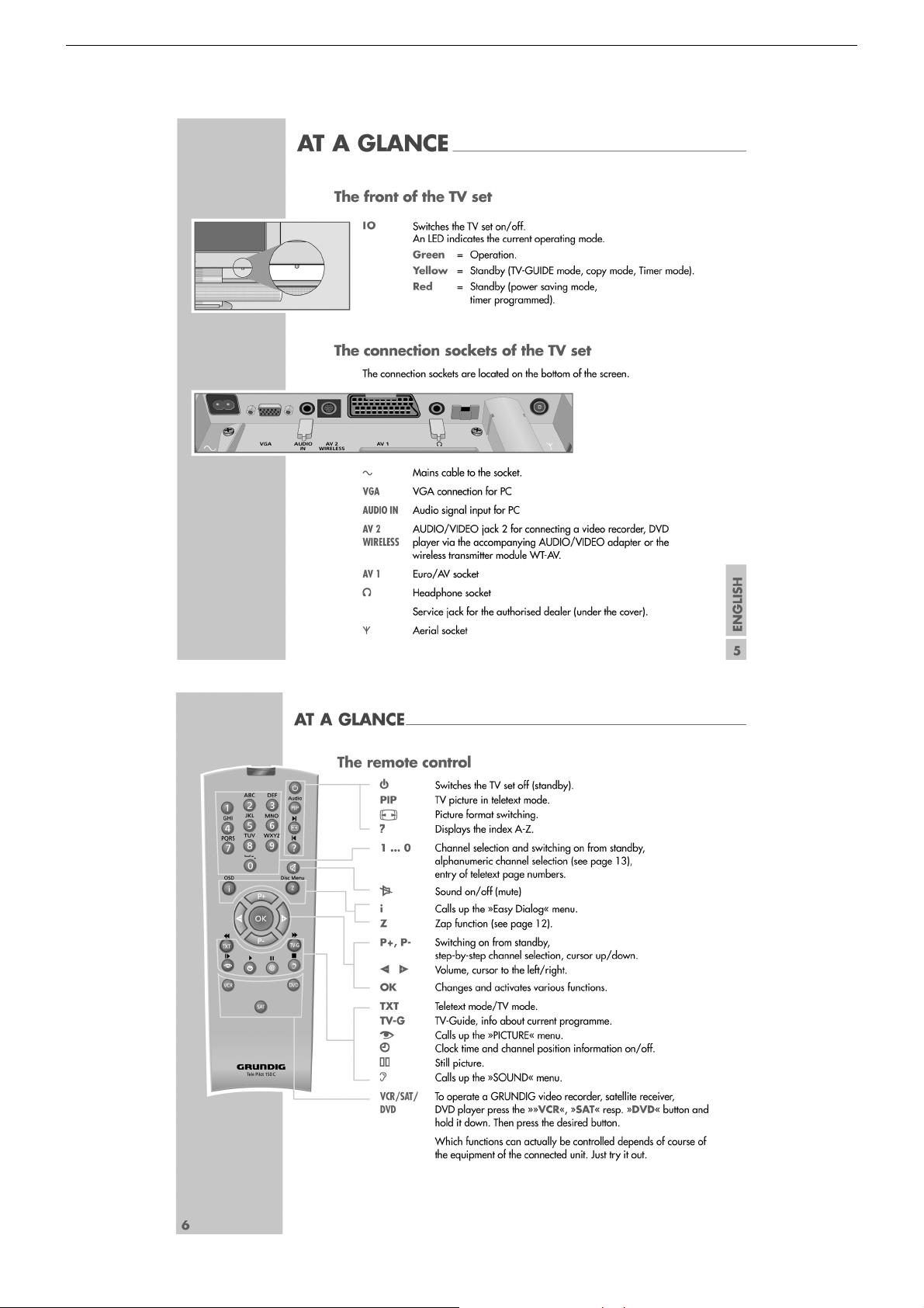
Anschlüsse Front / Connections Front
Kopfhörer
Headphones
Anschlüsse Rückwand / Connections Rear Panel
Euro AV 1 (schwarz/black)
Euro AV 2
Euro AV 3
Standard VGA ja / yes
Interface
Netzteil / Mains Stage
Netzspannung (Regelbereich)
Mains voltage (variable)
Netzfrequenz
Mains frequency
Leistungsaufnahme
Power consumption
Standby <1W
Datalink für VCR Fernbedienung, Decoder, 16:9 / Pin 8, Nachrüstung WT-AV1
datalink for VCR remote control, decoder capable, 16:9 / Pin 8, retrofitting WT-AV1
Für Wireless-Anschluss, Mini DIN 8-pin-Buchse, FBAS Eingang, R/L Eingang, Datalink für
51cm (20") 4:3 Format. Colour active Matrix TFT LCD.
0.6375mm (H) x 0.6375mm (W) pixel pitch
je 3 CCFL Lampen oben und unten
je 3 CCFL lamps up und down
170° vertikal, 170° horizontal
170° vertical, 170° horizontal
PLL Frequenz Synthesizer Tuning UHF/VHF, globale Pinbelegung
PLL frequency synthesizer tuning UHF/VHF, global pinning
PAL, SECAM, NTSC 4.43MHz + 3,58MHz
Deutsch A2 / German A2 (B/G/D/K)
Nicam 5.85 (B/G, L) + 6.52MHz (I)
TOP/FLOF Level 2.5, VPS, >2000 Seiten
TOP/FLOF level 2.5, VPS, >2000 pages
Stereo 3,5mm Klinkenbuchse, Lautstärke regelbar,
individuelle Tonkanalwahl bei 2-Ton-Empfang
Stereo 3.5mm jack, adjustable volume,
individual channel selection with dual-sound broadcasts
FBAS Ein-/Ausgang, RGB Eingang, SBAS Eingang, Megalogic,
CCVS in-/output, RGB input, SCVS input, Megalogic,
Taken for Wireless connection, Mini DIN 8-pin socket, CCVS in, R/L-in,
Für VGA-Monitor, 15-pin SubD-Buchse, 640 x 480 Pixel
Taken for VGA-Monitor, 15-pin SubD socket, 640 x 480 pixel
datalink for VCR remote control
Service-Schnittstelle (Software update/flash)
Service interface (software update/flash)
51cm
640 x 480 Pixel
400:1 (typ.)
2
400cd/m
25ms (typ.)
99 + 3 AV
B/G, I, D/K, K', M, L/L'
Stereo 3-Kanal 22W
Stereo 3-channel 22W
VCR Fernbedienung
220…240V
50 / 60Hz
ca. 40W
1 - 4
GRUNDIG Service THARUS 51 LCD 51-9410 DOLBY
Bedienhinweise Dieses Kapitel enthält Auszüge aus der Bedienungsanleitung. Weitergehende Informationen entnehmen Sie bitte der
gerätespezifischen Bedienungsanleitung, deren Materialnummer Sie in der entsprechenden Ersatzteilliste finden.
1 - 5
GRUNDIG Service THARUS 51 LCD 51-9410 DOLBY
1 - 6
GRUNDIG Service THARUS 51 LCD 51-9410 DOLBY
Operating Hints This chapter contains excerpts from the operating instructions. For further particulars please refer to the appropriate user
instructions the part number of which is indicated in the relevant spare parts list.
1 - 7
GRUNDIG Service THARUS 51 LCD 51-9410 DOLBY
1 - 8

GRUNDIG Service THARUS 51 LCD 51-9410 DOLBY
Service- und Sonderfunktionen
Aufruf des Service-Menüs: Taste "i" (EASY DIALOG)
Aufruf der Dialogzeile: Tasten "P+" / "P-" –> "OK"
Einstellung in der Dialogzeile ändern:Tasten "Ǹ" / " Ƿ" –> "
Zurück ins vorherige Menü: "blaue" Taste
Beenden des Menüs: Taste "i"
Servicemenü für Händler (Codezahl):"8500"
1. Einschaltfunktionen
1.1 ATS-Reset
Netzschalter "EIN" mit gedrückter Fernbedientaste "Ƿ".
– Gerät wird mit Analog-Grundwerten geladen.
– ATS-Bit wird gesetzt. Diese Option löst beim nächsten Einschalten
das ATS euro plus aus. Die bisherige Programmbelegung (Senderkanäle) wird gelöscht.
1.2 Programmsperre (Kindersicherung)
Die Tastenfolge "7 0 3 8 5 8 0" hebt die persönliche Kennzahl auf.
1.3 Software-Versionsnummer
Das Menü "EASY DIALOG" aufrufen. Durch Betätigen der "grünen"
Taste wird die Software-Versionsnummer angezeigt.
1.4 Flashprogrammierung
Benötigtes Equipment
Flash-Programmer F-Prog 1 / ab Version 2.0 oder
Service Toolbox Materialnummer 772004001200.
Erforderliche Hardware (Minimum)
Pentium-PC, Microsoft Windows 95
– freier Arbeitsspeicher 32MB
– CD-ROM-Laufwerk
– serielle Schnittstelle
– Internet-Zugang
Abrufen der aktuellen Gerätesoftware
Die Software ist in einem mit Grundig-Kundennummer und Passwort
geschützten Bereich im Internet unter Grundig/Partnerweb (B2B)
abrufbar.
Hinweis zum Abrufen der Software:
– Internet-Browser starten.
– http://partnerweb.grundig.de eingeben und starten.
– Folgen Sie der Menüführung unter "Kundendienst –> Software-
Download".
1.5 Direkte Display-Typ-Einstellung
Ist die Menüdarstellung auf Grund falscher Display-Typ-Einstellung
nicht mehr möglich, können Sie mit "Short-cuts" die korrekte Einstellung vornehmen.
Vor und nach der Direkteingabe muss das Gerät aus- und wieder
eingeschaltet werden!
Tasten "i", "rot" und Ziffer stellt den gewünschten Display-Typ im
Service ein. Folgende Ziffern geben den jeweiligen Display-Typ an:
1 LPL LC201V1
2 LPL LC201V02
3 LPL LC230W01
4 LPL LC300W01
5 LPL LC420W01
2. Sonderfunktionen im Menü "Installation"
2.1 Buchstaben-Eingabe
Das Menü "Buchstaben-Eingabe" über "EASY DIALOG" –> "Installation" –> "Sonderfunktionen" aufrufen.
Sie können die Buchstaben-Eingabe für die Programmwahl zwischen
"aus", "ein" und "mix" wählen.
2.2 "Tonskala" sichtbar oder unsichtbar für alle Programme
Das Menü "Tonskala" über "EASY DIALOG" –> "Installation" –>
"Sonderfunktionen" aufrufen.
Bei "aus" erscheint keine Balkenanzeige für die Lautstärke.
OK
"
2.3 Einschalten mit Programm "1" oder "automatisch"
Das Menü "Einschalten" über "EASY DIALOG" –> "Installation" –>
"Sonderfunktionen" aufrufen.
Auf "Programmplatz 1" oder "automatisch" stellen.
Bei "automatisch" wird der beim Ausschalten eingestellte Programmplatz beim Einschalten wieder aufgerufen (Last station memory).
2.4 "Megalogic Info" (nur wenn Megalogic-Gerät erkannt wurde).
Das Menü "Megalogic Info" über "EASY DIALOG" –> "Installation" –>
"Sonderfunktionen" aufrufen.
Die Megalogic-Steuerung kann auf "ein" bzw. "aus" geschaltet werden.
2.5 Statusanzeige
Das Menü "Statusanzeige" über "EASY DIALOG" –> "Installation" –>
"Sonderfunktionen" aufrufen.
Sie können wählen an welcher Position ("oben" oder "unten") die
Information über Tonart und Bildformat eingeblendet wird.
Bei "aus" wird nach Progammwechsel keine Information eingeblendet.
2.6 Automatische Lautstärke
Das Menü "Autom. Lautstärke" über "EASY DIALOG" –> "Installation"
–> "Sonderfunktionen" aufrufen.
In Stellung "ein" regelt der Ton-IC bei erhöhter Senderlautstärke (z. B.
erhöhter HUB bei der Werbung) die Lautstärke intern auf den normalen Wert zurück.
2.7 Rauschreduktion P1-P…
Das Menü "Rauschreduktion P1-P…" über "EASY DIALOG" –> "Installation" –> "Sonderfunktionen" aufrufen. Sie können die Rauschreduktion für die Programme 1-P… auf "aus", "gering" oder "automatisch" stellen.
Bei "manuell" wird angezeigt, dass ein oder mehrere Programme
unterschiedliche Einstellungen haben.
2.8 Bildschärfe P1-P…
Das Menü "Bildschärfe P1-P…" über "EASY DIALOG" –> "Installation"
–> "Sonderfunktionen" aufrufen.
Die Bildschärfe wird für alle Programme eingestellt.
2.9 Farbdeckung
Das Menü "Farbdeckung" über "EASY DIALOG" –> "Installation" –>
"Sonderfunktionen" aufrufen.
Die Farbdeckung (Luma-Delay) wird programmplatzbezogen eingestellt.
3. Service-Einstellungen für den Fachhandel
3.1 Bildeinstellungen
3.1.1 Weißabgleich
Das Menü "Weißabgleich" über "EASY DIALOG" –> "Installation" –>
"Servicemenü für Händler" –> "8500" –> "Bildeinstellungen" aufrufen.
Den Wert für "rot", "grün" und "blau" so einstellen, dass es weiß ergibt
(siehe Abgleich Punkt 5).
Hinweis:
Nach Neuaufruf des Menüs ist der Wert der größten Komponente
immer 511, die anderen Werte werden umgerechnet.
3.1.2 AD-Wandlerabgleich
Das Menü "automatisch – ja" über "EASY DIALOG" –> "Installation" –>
"Servicemenü für Händler" –> "8500" –> "Bildeinstellungen" –> "ADWandlerabgleich" aktivieren.
Das Menü "Automatischen Abgleich starten" anwählen und warten bis
das Menü wieder sichtbar ist.
Gegebenenfalls kann der AD-Wandlerabgleich manuell durchgeführt
werden.
– Das Menü "automatisch – nein" über "EASY DIALOG" –> "Installa-
tion" –> "Servicemenü für Händler" –> "8500" –> "Bildeinstellungen" –> "AD-Wandlerabgleich" deaktivieren.
– Schwarzwertabgleich
– Gerät auf AV-Stellung (Schwarzbild)
– Menü "Schwarzwertabgleich" aufrufen.
– Den Wert für "rot", "grün" und "blau" so einstellen, dass der
Übergang der Farbtreppe (Testbild) für alle 3 Farben an der
gleichen Stelle liegt (R,G,B gerade sichtbar). Dabei sollen die
Reglerwerte für die Komponenten möglichst nahe am Vorgabewert 248 bleiben.
– Offset so einstellen, dass das Farbfenster innerhalb des mittleren
Rahmen ist.
1 - 9

GRUNDIG Service THARUS 51 LCD 51-9410 DOLBY
– AD-Wandlerverstärkung
– Gerät auf AV-Stellung (Schwarzbild)
– Menü "AD-Wandlerverstärkung" aufrufen.
– Den Wert für "rot", "grün" und "blau" so einstellen, dass der
Übergang der Farbtreppe (Testbild) für alle 3 Farben an der
gleichen Stelle liegt (R,G,B gerade sichtbar). Dabei sollen die
Reglerwerte für die Komponenten möglichst nahe am Vorgabewert 178 bleiben.
3.1.3 Blauen Bildschirmhintergrund ein/ausschalten
Das Menü "Blauer Bildschirm" über "EASY DIALOG" –> "Installation"
–> "Servicemenü für Händler" –> "8500" –> "Bildeinstellungen" aufrufen.
Auf "ein" oder "aus" stellen.
3.2 Hardware-Ausstattung
3.2.1 Displaytyp
Das Menü "Bildröhrentyp" über "EASY DIALOG" –> "Installation" –>
"Servicemenü für Händler" –> Kennzahl "8500" –> "HardwareAustattung" aufrufen.
Bildröhrentyp/Displaytyp einstellen (siehe Abgleich Punkt 1).
3.2.2 ZF-Typ
Das Menü "ZF-Typ" über "EASY DIALOG" –> "Installation" –>
"Servicemenü für Händler" –> Kennzahl "8500" –> "HardwareAustattung" aufrufen.
Nach Wechsel des NVM muss der ZF-Typ eingestellt werden:
Inland-Geräte: Inland
Multi 8-Geräte: Multi 8
Multi 9-Geräte: Multi 9 (siehe Abgleich Punkt 2).
3.2.3 Tuner-Typ
Das Menü "Terr. Tuner" über "EASY DIALOG" –> "Installation" –>
"Servicemenü für Händler" –> Kennzahl "8500" –> "HardwareAustattung" aufrufen.
Auf im Gerät eingebauten Tuner einstellen.
3.2.4 Fernbedienung
Das Menü "Fernbedienung" über "EASY DIALOG" –> "Installation" –>
"Servicemenü für Händler" –> Kennzahl "8500" –> "HardwareAustattung" aufrufen.
Auf "TP150" oder "PR11" einstellen.
3.2.5 Subwoofer
Das Menü "Subwoofer" über "EASY DIALOG" –> "Installation" –>
"Servicemenü für Händler" –> Kennzahl "8500" –> "HardwareAustattung" aufrufen.
Auf "ja" oder "nein" stellen.
3.2.6 Front-LED
Das Menü "Front-LED" über "EASY DIALOG" –> "Installation" –>
"Servicemenü für Händler" –> Kennzahl "8500" –> "HardwareAustattung" aufrufen.
Auf "3 Colors" oder "1 Color" stellen.
3.3 Sonderfunktionen
3.3.1 Watchdog On/Off
Das Menü "Watchdog" über "EASY DIALOG" –> "Installation" –>
"Servicemenü für Händler" –> "8500" –> "Sonderfunktionen" aufrufen.
Wird der Watchdogtimer nicht in regelmäßigen Zeitabständen zurückgesetzt, wird ein Neustart ausgelöst.
Watchdog auf "aus" oder "ein" schalten.
3.3.2 IR-Dataprogrammer
Das Menü "IR-Dataprogrammer" über "EASY DIALOG" –> "Installation"
–> "Servicemenü für Händler" –> "8500" –> "Sonderfunktionen" aufrufen.
Mit der Taste "OK" können mit dem IR-Dataprogrammer 2 max. 99
Programmplätze mit Daten für Kanal, Norm, Peri, 6-stellige Sendereinblendung, Finetuning-Mitte und Lautstärke-Offset "0" abgespeichert
werden.
3.3.3 AGC-Einstellung
Das Menü "AGC-Einstellung" über "EASY DIALOG" –> "Installation"
–> "Servicemenü für Händler" –> Kennzahl "8500" –> "Sonderfunktionen" aufrufen.
Wert so einstellen, dass das Bild gerade rauschfrei ist (siehe Abgleich
Punkt 4).
3.3.4 TV-Guide-Flash löschen
Das Menü "TV-Guide-Flash löschen" über "EASY DIALOG" –> "Installation" –> "Servicemenü für Händler" –> Kennzahl "8500" –> "Sonderfunktionen" aufrufen.
Nach Drücken der Taste "OK" wird das TV-Guide-Flash in einen
definierten Zustand versetzt. Ungültige und fehlerhafte Werte werden
zurückgesetzt.
3.3.5 Videotext-Level-2.5-Unterstützung
Das Menü "Videotext Level 2.5" über "EASY DIALOG" –> "Installation"
–> "Servicemenü für Händler" –> Kennzahl "8500" –> "Sonderfunktionen" aufrufen.
Auf "ja" oder "nein" stellen.
4. Ton-Einstellungen
Mit "blauer" Taste das Menü "Ton" aufrufen.
Im Menü "Voreinstellungen" sind die Einstellungen "Sprache", "Musik"
oder "manuell" anwählbar.
Die "manuell"-Einstellung lässt eine Einstellung des Klanges zu. In den
anderen Einstellungen sind bestimmte Werte fest vorgegeben.
5. Bild-Einstellungen
Mit roter Taste das Menü "Bild" aufrufen.
– Im Menü "Voreinstellungen" sind die Einstellungen "Am Tag", "Am
Abend" und "manuell" anwählbar.
Die "manuell"-Einstellung lässt eine Regulierung von Kontrast,
Schärfe zu. In den anderen Einstellungen sind bestimmte Werte fest
vorgegeben.
– Im Menü "Neigungswinkel" kann Helligkeit/Kontrast je nach
Betrachtungswinkel eingestellt werden.
6. Einstellungen über die Senderbelegung
6.1 Zwangseinstellungen im Programm-Mode
Das Menü "Tonkanal" über "EASY DIALOG" –> "Programmtabelle" –>
"grüne Taste" –> "Kanaleinstellungen ändern" aufrufen.
Sie können zwischen "automatisch", "Mono", "Mono B" und "Mono C"
wählen.
Mono B = Orginalton
Mono C = Bei Digitalem Ton-Empfang (Nicam).
7. Werkseinstellung
Tasten "i", "rot" und "OK" ruft die Werkseinstellwerte auf.
1 - 10

GRUNDIG Service THARUS 51 LCD 51-9410 DOLBY
Service and Special Functions
Call up the Service Menu: Button "i" (EASY DIALOG)
Call up the dialogue line: Buttons "P+" / "P-" –> "OK"
Changing the setting in the dialogue line: Buttons "Ǹ " / " Ƿ" –> "
Back to previous menu: "Blue" button
Exit menu: Button "i"
Service menu for retailer (code number):"8500"
OK
"
1. Switching-on Options
1.1 ATS Reset
Press mains button "ON" while holding down the "Ƿ" button on the
remote control.
– The basic analogue values are loaded.
– The ATS bit is set. When switching on the next time, this option
releases the ATS euro plus function. The current programme
allocation (channels) is cleared.
1.2 Electronic Programme Lock (parental lock)
Enter the key sequence "7 0 3 8 5 8 0" to cancel your personal code
number.
1.3 Software Version Number
Call up the "EASY DIALOG" menu. Pressing the green button indicates the software version number.
1.4 Flash Programming
Required equipment
Flash programmer F-Prog 1 / from version 2.0 on or
Service Toolbox part number 772004001200.
Required hardware
Pentium-PC, Microsoft Windows 95
– Free memory of 32MB
– CD-ROM drive
– COM port
– Internet access
Calling up the current TV software
The software can be called up from an area of the Grundig partnerweb
(B2B), protected via a Grundig customer number and a password.
Note to downloading the software:
– Start the Internet Browser.
– Input the address http://partnerweb.grundig.com and start.
– Follow the menu guide in "Service –> Software Download".
1.5 Direct Display Type Adjustment
If the menus can not be displayed any longer due to an incorrect display
type adjustment, you can carry out the correct adjustment with the help
of key short cuts.
Before and after the direct entry, the unit must be switched off and on
again!
The "i", "red" and numeric keys select the desired display type in the
service mode. The following digits indicate the display types:
1 LPL LC201V1
2 LPL LC201V02
3 LPL LC230W01
4 LPL LC300W01
5 LPL LC420W01
2.3 Switching on with Programme "1" or automatically
Call up the "Switch on" menu via "EASY DIALOG" –> "Installation" –>
"Special functions" .
Set the option "Preset 1" or "Automatic".
With the "automatc" setting, the programme position selected when
switching off is selected again when switching the set on again (Last
station memory).
2.4 "Megalogic Info" (only if a connected Megalogic set is identified)
Call up the "Megalogic info" menu via "EASY DIALOG" –>
"Installation" –> "Special functions".
The Megalogic control can be switched to "on" or "off".
2.5 Status Display
Call up the "Status Display" menu via "EASY DIALOG" –>
"Installation" –> "Special functions".
You may select the position (top or bottom) where the information
about the sound mode and the picture format is displayed.
With the "off" option, no information is displayed when changing the
programme.
2.6 Automatic Volume
Call up the "Automatic volume" menu via "EASY DIALOG" –>
"Installation" –> "Special functions".
In the "ON" position, the sound IC regulates the volume internally to
the normal value (e.g. increased deviation in the case of advertising).
2.7 Noise Reduction P1-P…
Call up the "Noise reduction P1-P…" menu via "EASY DIALOG" –>
"Installation" –> "Special functions. For the programmes 1-P… you
may set the noise reduction to "off", "low" or "automatic".
"Manual" indicates that one or several programmes have different
settings.
2.8 Picture Sharpness P1-P…
Call up the "Sharpness P1-P…" menu via "EASY DIALOG" –>
"Installation" –> "Special functions".
The picture sharpness is set for all programmes.
2.9 Colour Match
Call up the "Colour match" menu via "EASY DIALOG" –> "Installation"
–> "Special functions".
The colour match (luma delay) is set for every programme.
3. Service Settings for the Retailer
3.1 Picture Settings
3.1.1 White Balance
Call up the "White balance" menu via "EASY DIALOG" –> "Installation"
–> "Dealer service menu" –> Code number "8500" –> "Picture settings".
Adjust the values for "red", "green" and "blue" so that a white picture
is obtained (see Alignment, Point 5).
Note:
When calling up the menus again, the value of the largest component
is always 511, the other values are converted.
3.1.2 AD Converter
Call up the "Automatic – Yes" menu via "EASY DIALOG" –> "Installation" –> "Dealer service menu" –> Code number "8500" –> "Picture
settings" –> "@AD-Wandlerabgleich".
Call up the "@Automatischer Abgleich starten" menu and wait up to the
menu that is shown on the display.
2. Special Functions in the "Installation" Menu
2.1 Entry of Letters
Call up the "Letter entry" menu via "EASY DIALOG" –> "Installation"
–> "Special functions".
You may select between "off", "on" and "mix" for the programme
selection letter entry.
2.2 Visible or Unvisible "Sound scale" for all Programmes
Call up the "Sound scale" menu via "EASY DIALOG" –> "Installation"
–> "Special functions".
With "off" selected, no volume bar is displayed.
If it necessary the AD Converter can be adjusted manually.
– Call up the "Automatic – No" menu via "EASY DIALOG" –> "Instal-
lation" –> "Dealer service menu" –> Code number "8500" –>
"Picture settings" –> "@AD-Wandlerabgleich".
– Black Level Balance
– Select the AV position (black picture) on the TV set.
– Call up the "Black level balance" menu.
– Adjust the "red", "green" and "blue" values in such a way that the
transition of the colour scale (test pattern) is at the same place for
all 3 colours (R,G,B just visible). The control values for the
components should remain as close as possible to the given value
248.
– Adjust the offset in such a way that the colour window is located
inside the centre frame.
1 - 11

GRUNDIG Service THARUS 51 LCD 51-9410 DOLBY
– AD Converter Gain
– Select the AV position (black picture) on the TV set.
– Call up the "@AD-Wandlerverstärkung" menu.
– Adjust the "red", "green" and "blue" values in such a way that the
transition of the colour scale (test pattern) is at the same place for
all 3 colours (R,G,B just visible). The control values for the
components should remain as close as possible to the given value
178.
3.1.3 Switching the Blue Screen Background On and Off
Call up the "Blue screen" menu via "EASY DIALOG" –> "Installation"
–> "Dealer service menu" –> Code number "8500" –> "Picture settings".
Select "on" or "off".
3.2 Hardware Equipment
3.2.1 Display type
Call up the "Tube type" menu via "EASY DIALOG" –>
"Installation" –> "Only for the retailer" –> Code number "8500" –>
"Hardware equipment".
Select the appropriate picture tube type / display type.
3.2.2 IF Type
Call up the "IF Type" menu via "EASY DIALOG" –> "Installation" –>
"Only for the retailer" –> Code number "8500" –> "Hardware equipment".
After replacing the NVM, it is necessary to adjust the IF type:
Inland sets: National
Multi-8 sets: Multi 8
Multi-9 sets: Multi 9
(see Alignment, Point 2).
3.2.3 Tuner Type
Call up the "Terrestrial tuner" menu via "EASY DIALOG" –> "Installation" –> "Only for the retailer" –> Code number "8500" –> "Hardware
equipment".
Select the appropriate tuner type.
3.2.4 Remote Control
Call up the "Remote control" menu via "EASY DIALOG" –> "Installation" –> "Only for the retailer" –> Code number "8500" –> "Hardware
equipment".
Select "TP150" or "PR11".
3.2.5 Subwoofer
Call up the "Subwoofer" menu via "EASY DIALOG" –> "Installation"
–> "Only for the retailer" –> Code number "8500" –> "Hardware
equipment".
Select "yes" or "no".
3.2.6 Front-LED
Call up the "Front-LED" menu via "EASY DIALOG" –> "Installation"
–> "Only for the retailer" –> Code number "8500" –> "Hardware
equipment".
Select "3 Colors" or "1 Color".
3.3 Special Functions
3.3.1 Watchdog On/Off
Call up the "Watchdog" menu via "EASY DIALOG" –> "Installation"
–> "Dealer service menu" –> Code number "8500" –> "Special
functions".
If the Watchdog timer is not reset in regular intervals, a new start is
initialized.
Set the Watchdog to "off" or "on".
3.3.2 IR Data Programmer
Call up the "IR-Data programmer" menu via "EASY DIALOG" –>
"Installation" –> "Dealer service menu" –> Code number "8500" –>
"Special functions". Using the "OK" button, it is possible to store up to
99 programme positions with data for channel, TV standard, Peri,
6-position station name, centre fine tuning, and "0" volume offset, with
the help of the IR data programmer.
3.3.3 AGC Setting
Feed in a standard channel raster without finetuning in band 1.
Call up the "AGC setting" menu via "EASY DIALOG" –> "Installation"
–> "Dealer service menu" –> Code number "8500" –> "Special
functions".
Adjust the value so that the picture is just free of noise (see Alignment,
Point 4).
3.3.4 Cancel EPG Flash
Call up the "Cancel EPG flash" menu via "EASY DIALOG" –> "Installation" –> "Dealer service menu" –> Code number "8500" –> "Special
functions".
Pressing the "OK" button will clear the EPG Flash.
3.3.5 Teletext Level 2.5 Support
Call up the "Teletext level 2.5" menu via "EASY DIALOG" –>
"Installation" –> "Dealer service menu" –> Code number "8500" –>
"Special functions".
Select "yes" or "no".
4. Sound Settings
Press the "blue" button to call up the "Sound" menu.
The settings "Speech", "Music" or "manual" can be selected in the
"Defaults" menu.
The "Manual" setting allows you to adjust the sound to suit your taste.
For the other settings, specific values are preprogrammed.
5. Picture Settings
Press the "red" button to call up the "Picture" menu.
– In the "Defaults" menu, the settings "Day", "Night", and "Manual"
can be selected.
With the "Manual" option, you may set the contrast and the picture
sharpness. For the other settings, specific values are preprogrammed.
– In the "Tilt angle" menu brightness/contrast can be adjusted accor-
ding to the viewing angle.
6. Settings via the Channel Allocation
6.1 Forced Settings in Programme Mode
Call up the "Sound channel" menu via "EASY DIALOG" –>
"Preset List" –> "green button" –> "Edit channel settings".
You may select between "Automatic", "Mono", "Mono B" and
"Mono C".
Mono B = Original sound track
Mono C = For digital sound reception (Nicam).
7. Factory Settings
Press the "i", "red" and OK buttons to call up the factory settings.
1 - 12
GRUNDIG Service THARUS 51 LCD 51-9410 DOLBY
Servicehinweise
Leitungsverlegung
Nach erfolgter Reparatur ist es notwendig, die Leitungsführung wieder
in den werkseitigen Zustand zu versetzen um evtl. spätere Ausfälle
oder Störungen zu vermeiden.
1. Öffnen des Gerätes
– Vor dem Öffnen des Gerätes dieses vom Netz trennen.
– Sicherheitshinweise beachten (siehe Service Manual "Sicherheit",
Materialnummer 720108000001).
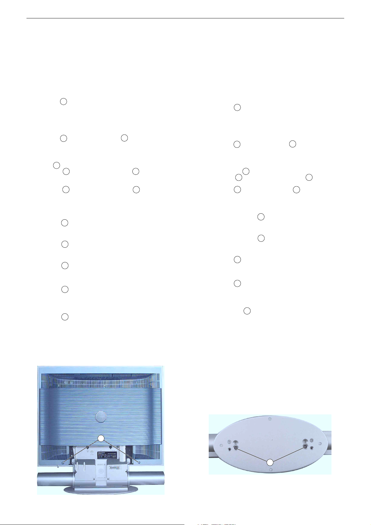
1.1 Rückwand
– 2 Schrauben A (Fig. 1) herausdrehen und Geräterückwand abneh-
men.
2. Ausbauhinweise
Hinweis: TV-Gerät auf eine weiche kratzfreie Unterlage legen.
2.1 Soundsystem
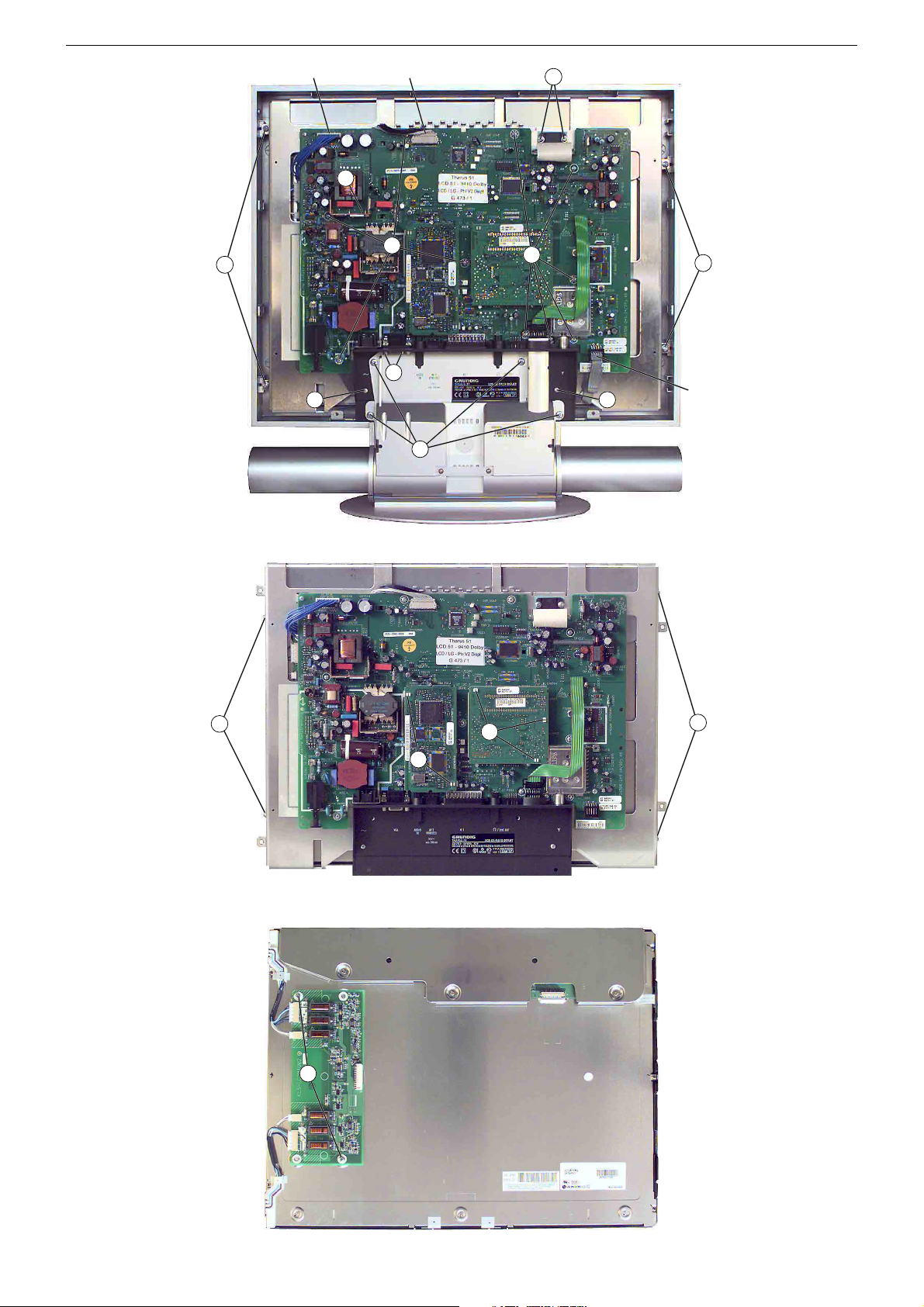
– 2 Schrauben B (Fig. 2) und 4 Schrauben C (Fig. 3) herausdrehen.
– Soundsystem nach unten abziehen.
2.2 Chassisplatte
– Soundsystem ausbauen (Punkt 2.1).
– Klammer D (Fig 3) abnehmen
– 2 Schrauben E (Fig. 3) und 2 Stehbolzen F (Fig. 3) heraus-
drehen.
– Buchsenabdeckung abnehmen.
– 2 Schrauben G (Fig. 3) und 11 Schrauben H (Fig. 3) heraus-
drehen.
– Chassisplatte herausnehmen und gegebenenfalls Steck-
verbindungen CST_D13A, CST_DIS1/2, ST_IRBA (Fig. 3) lösen.
2.3 Falconic-Platte
– 2 Rasthaken I (Fig. 4) lösen.
– Falconic-Platte herausnehmen.
2.4 M2-Platte
– 3 Rasthaken J (Fig. 4) lösen.
– M2-Platte herausnehmen.
2.5 Display
– 4 Schrauben K (Fig. 3) herausdrehen.
– Gegebenenfalls Steckverbindungen CST_D13A, CST_DIS1/2,
ST_IRBA (Fig. 3) lösen.
– Display herausnehmen.
– 4 Schrauben L (Fig. 4) herausdrehen.
– Trägerblech mit Chassisplatte abnehmen.
2.6 Backlight-Inverter
– Display ausbauen (Punkt 2.5).
– 2 Schrauben M (Fig. 5) herausdrehen.
– Backlight-Inverter abnehmen und gegebenenfalls Steck-
verbindungen lösen.
3. Wichtige Masseverbindungen!
Beim Zusammenbau des Gerätes ist darauf zu achten, dass die
Masseverbindungen zwischen den einzelnen Baugruppen gewähr-
leistet sind.
Service Instructions
Wiring
On completion of the repairs the leads must be laid out as originally
fitted at the factory to avoid later failures or disturbances.
1. Opening the Set
– Disconnect the set from the mains before opening it.
– Observe the safety instructions (see Service Manual "Safety", part
number 720108000001)
1.1 Rear Panel
– Undo 2 screws A (Fig. 1) and remove the rear panel.
2. Disassembly Instructions
Note: place the TV set on a soft and non scratching pad.
2.1 Sound System
–
Undo 2 screws B
– Pull the Sound system off in downward direction.
2.2 Chassis Board
– Remove the Sound system (Point 2.1).
– Remove the clamp D (Fig. 3).
– Undo 2 screws E
–
Remove the sockets cover.
– Undo 2 screws G (Fig. 3) and 11 screws H (Fig. 3).
–
Remove the chassis board. For this, disengage the connectors
CST_D13A, CST_DIS1/2, ST_IRBA (Fig. 3)
2.3 Falconic Board
– Release 2 locking caches I (Fig. 4).
– Remove the Falconic Board.
2.4 M2 Board
– Release 3 locking caches J (Fig. 4).
– Remove the Falconic Board.
2.5 Display
– Undo 4 screws K (Fig. 3).
– Disengage the connectors CST_D13A, CST_DIS1/2, ST_IRBA
(Fig. 3) if necessary.
– Remove the display.
– Undo 4 screws L (Fig. 4).
– Remove the sheet metal holder with chassis board.
2.6 Backlight Inverter
– Remove the Display (Point 2.5).
– Undo the 2 screws M (Fig. 5).
– Remove the Backlight Inverter.
necessary.
3. WARNING: Chassis Connections!
When reassembling the TV set, make sure that the ground connections
between the individual componentries are restored.
(Fig. 2) and 4 screws C
(Fig. 3) and
2 distance bolts F
For this, disengage the connectors if
(Fig. 3).
(Fig. 3).
if necessary.
A
Fig. 1 Fig. 2
1 - 13
B
GRUNDIG Service THARUS 51 LCD 51-9410 DOLBY
Fig. 3
CST_D13A CST_DIS1/2
D
H
K
F
E E
C
G
H
K
ST_IRBA
Fig. 4
Fig. 5
L
I
M
J
L
1 - 14
GRUNDIG Service THARUS 51 LCD 51-9410 DOLBY
Abgleich
Alle nicht beschriebenen Einstellelemente sind werkseitig abgeglichen und dürfen im Servicefall nicht verstellt werden.
i
Aufruf des Service-Menüs: Taste "
Aufruf der Dialogzeile: Tasten "
Einstellung in der Dialogzeile ändern: Tasten "Ǹ" / " Ƿ" –> "
Zurück ins vorherige Menü: "blaue" Taste
Beenden des Menüs: Taste "i"
Servicemenü für Händler (Codezahl): "8500"
Messgeräte: 100MHz Oszilloskop mit Tastkopf 10:1, Farbbildgenerator.
Servicearbeiten nach Austausch …
… des Displays, Abgleich 5
… der Chassisplatte, Ableich 1…4, 6
… der M2-Platte, Ableich 5, 6
… des Tuners, Ableich 3, 4
Abgleich Vorbereitung Abgleichvorgang
1. Displaytyp
2. ZF-Typ
3. Terr. Tuner-Typ
4. Tuner-AGC
5. Weißwert
6. AD-Wandler
7. Bildgeometrie
Bildgeometrie
VGA
Menü "Displaytyp" über "EASY DIALOG" –> "Installation"
–> "Servicemenü für Händler" –> "8500" –> "HardwareEinstellungen" aufrufen.
Menü "ZF-Typ" über "EASY DIALOG" –> "Installation" –>
"Servicemenü für Händler" –> "8500" –> "Hardware-Einstellungen" aufrufen.
Menü "Terr. Tuner" über "EASY DIALOG" –> "Installation"
–> "Servicemenü für Händler" –> Kennzahl "8500" –> "Hardware-Einstellungen" aufrufen.
100MHz-Oszilloskop an Tunerkontakt 10 oder 11 gegen
Tunermasse anschließen.
Testbild (mit abgeschaltetem Tonträger) über die Antenne
einspeisen, 70…80dBµV.
Das Menü "AGC-Einstellung" über "EASY DIALOG " –>
"Installation" –> "Servicemenü für Händler" –> "8500" –>
"Sonderfunktionen" aufrufen.
Grautreppe mit Burst einspeisen.
Weißbalance: Mittenstellung
Kontrast: Maximum
Farbkontrast: Mittelwert
Bildschirmhelligkeit: Mittelwert
Neigungswinkel: Mittelwert
Menü "Weißabgleich" über "EASY DIALOG" –> "Installation" –> "Servicemenü für Händler" –> "8500" –> "Bildeinstellungen" aufrufen.
Das Menü "automatisch – ja" über "EASY DIALOG" –>
"Installation" –> "Servicemenü für Händler" –> "8500" –>
"Bildeinstellungen" –> "AD-Wandlerabgleich" aktivieren.
Das Menü "Bildgeometrie" über "EASY DIALOG" –> "Installation" –> "Servicemenü für Händler" –> "8500" aufrufen.
Geometrietestbild einspeisen.
Reset: Das Feld "Reset" enthält:
- entweder die optimalen Bildgeometriedaten des Gerätes
aus der Fertigung.
- oder einen mittleren Datensatz aus dem ROM, wenn das
Gerät mit dem Notdatensatz gestartet wurde.
Nach einem Fehlabgleich können Sie diese Grundwerte
jederzeit wieder laden:
Menü "Reset" über "EASY DIALOG " –> "Installation" –>
"Servicemenü für Händler" –> "8500" –> Bildgeometrie
aufrufen.
Gerät in Programmstellung "AV3" schalten und Geometriebild über die VGA-Buchse einspeisen.
Menü "Reset" über "EASY DIALOG " –> "Installation" –>
"Servicemenü für Händler" –> "8500" –> Bildgeometrie
aufrufen.
" (EASY DIALOG)
P+
" / "P-" –> "OK"
OK
"
Auf eingebautes Display einstellen:
1 LPL LC201V1
2 LPL LC201V02
3 LPL LC230W01
4 LPL LC300W01
5 LPL LC420W01
Auf im Gerät eingebauten ZF-Typ einstellen.
Inland, Multi 8 oder Multi 9.
Auf den im Gerät eingebauten Tuner einstellen.
Auf 300-350mVss einstellen.
Die Werte für rot, grün und blau so einstellen, dass das Bild
unbunt wird.
Hinweis:
Nach der Einstellung und dem Verlassen des Menüs ist der
Wert der größten Komponente immer 511, die anderen
Werte werden umgerechnet.
Das Menü "Automatischen Abgleich starten" anwählen und
warten bis das Menü wieder sichtbar ist.
Mit Bildhöhe, Vert. Pos., Horiz. Pos.,Bildbreite das Testbild
in Bildschirmmitte bringen und symmetrische Beschreibung
des Displays einstellen.
Speichern:
Der eingestellte Wert wird durch Drücken der "gelben" Taste
gespeichert.
Die Bildgeometrie stellt sich nach jedem Einschalten auf
den zuletzt abgespeicherten Wert ein.
Mit Vert. Pos., Horiz. Pos., Bildbreite das Testbild in
Bildschirmmitte bringen und symmetrische Beschreibung
des Displays einstellen.
Speichern:
Der eingestellte Wert wird durch Drücken der "gelben" Taste
gespeichert.
Die Bildgeometrie stellt sich nach jedem Einschalten auf
den zuletzt abgespeicherten Wert ein.
2 - 1
GRUNDIG Service THARUS 51 LCD 51-9410 DOLBY
Alignment
All adjustment controls not mentioned in this description are adjusted during production and must not be re-adjusted in the case of repairs.
i
Call up the service menu: Button "
Call up the dialogue line: Buttons "
Change setting in the dialogue line: Buttons " Ǹ" / "Ƿ" –> "
Back to previous menu: "blue" button
Exit menu: Button "i"
Service menu for the dealer (code no.): "8500"
Measuring instruments: 100MHz oscilloscope with 10:1 test probe, colour test pattern generator.
Service work after changing the …
… Display, Adjustment 5
… Chassis Board, Adjustment 1…4, 6
… M2 Board, Adjustment 5, 6
… Tuner, Adjustment 3, 4
Alignment Preparations Alignment procedure
1. Display Type
2. IF Type
3. Terr. Tuner Type
4. Tuner AGC
5. White level
6. AD Converter
7. Screen geometry
Screen geometry
VGA
Call up the "Display type" menu via "EASY DIALOG" –>
"Installation" –> "Dealer service menu" –> Code number
"8500" –> "Hardware equipment".
Call up the "IF Type" menu via "EASY DIALOG" –>
"Installation" –> "Dealer service menu" –> "8500" –> "Hardware equipment".
Call up the "Terrestrial tuner" menu via "EASY DIALOG" –>
"Installation" –> "Dealer service menu" –> Code number
"8500" –> "Hardware equipment".
Connect the 100MHz oscilloscope to the tuner contact 10 or
11 and to tuner ground.
Feed in a test pattern (sound carrier switched off) via the
aerial, 70…80dBµV.
Call up the "AGC setting" menu via "EASY DIALOG" –>
"Installation" –> "Dealer service menu" –> "8500" –> "Special functions".
Feed in a grey scale test pattern with burst.
White balance: Central position
Contrast: Maximum
Colour contrast: Mean value
Screen brighness: Mean value
Tilt angle: Mean value
Call up the "White level alignment" menu via "EASY
DIALOG" –> "Installation" –> "Dealer service menu" –>
"8500" –> "Picture settings".
Call up the "Automatic – Yes" menu via "EASY DIALOG" –>
"Installation" –> "Dealer service menu" –> Code number
"8500" –> "Picture settings" –> "@AD-Wandlerabgleich".
Call up the "Screen geometry" menu via "EASY DIALOG" –>
"Installation" –> "Dealer service menu" –> "8500".
Feed in a geometry test pattern.
Reset: The "Reset" field contains:
- either the optimum picture geometry data set at the
factory,
- or an average data record from the ROM if the set has
been started with the emergency data record.
After an incorrect alignment you may reload this basic data
at any time:
Call up the "Reset" menu via "EASY DIALOG" –> "Installation"
–> "Dealer service menu" –> "8500" –> "Screen geometry".
Switch the set to channel position "AV3" and feed in a
geometry test pattern via the VGA socket.
Call up the "Reset" menu via "EASY DIALOG" –> "Installation"
–> "Dealer service menu" –> "8500" –> "Screen geometry".
" (EASY DIALOG)
P+
" / "P-" –> "OK"
OK
"
Select the appropriate display type:
1 LPL LC201V1
2 LPL LC201V02
3 LPL LC230W01
4 LPL LC300W01
5 LPL LC420W01
Adjust to IF Type built into the set.
National, Multi 8, Multi 9.
Select the appropriate tuner type.
Set to 300-350mVpp.
Adjust the values for red, green and blue so that the picture
becomes achromatic.
Note:
When calling up the menus again, the value of the largest
component is always 511, the other values are converted.
Call up the "@Automatischer Abgleich starten" menu and
wait up to the menu that is shown on the display.
Using the controls for "Height", "Vert. shift", "Horiz. shift",
and "Width", move the test pattern into the centre of the
picture screen, and then adjust a symmetrical display
reading.
Saving:
The set value is saved by pressing the "yellow" button.
The picture geometry adjusts itself to the last saved value
when switching the TV set on again.
Using the controls for Vert. Pos., Horiz. Pos., and Picture
Width, move the test pattern into the centre of the picture
screen, and then adjust a symmetrical display reading.
Saving:
The set value is saved by pressing the "yellow" button.
The picture geometry adjusts itself to the last saved value
when switching the TV set on again.
2 - 2
GRUNDIG Service THARUS 51 LCD 51-9410 DOLBY
Platinenabbildungen und Schaltpläne / Layout of the PCBs and Circuit Diagrams
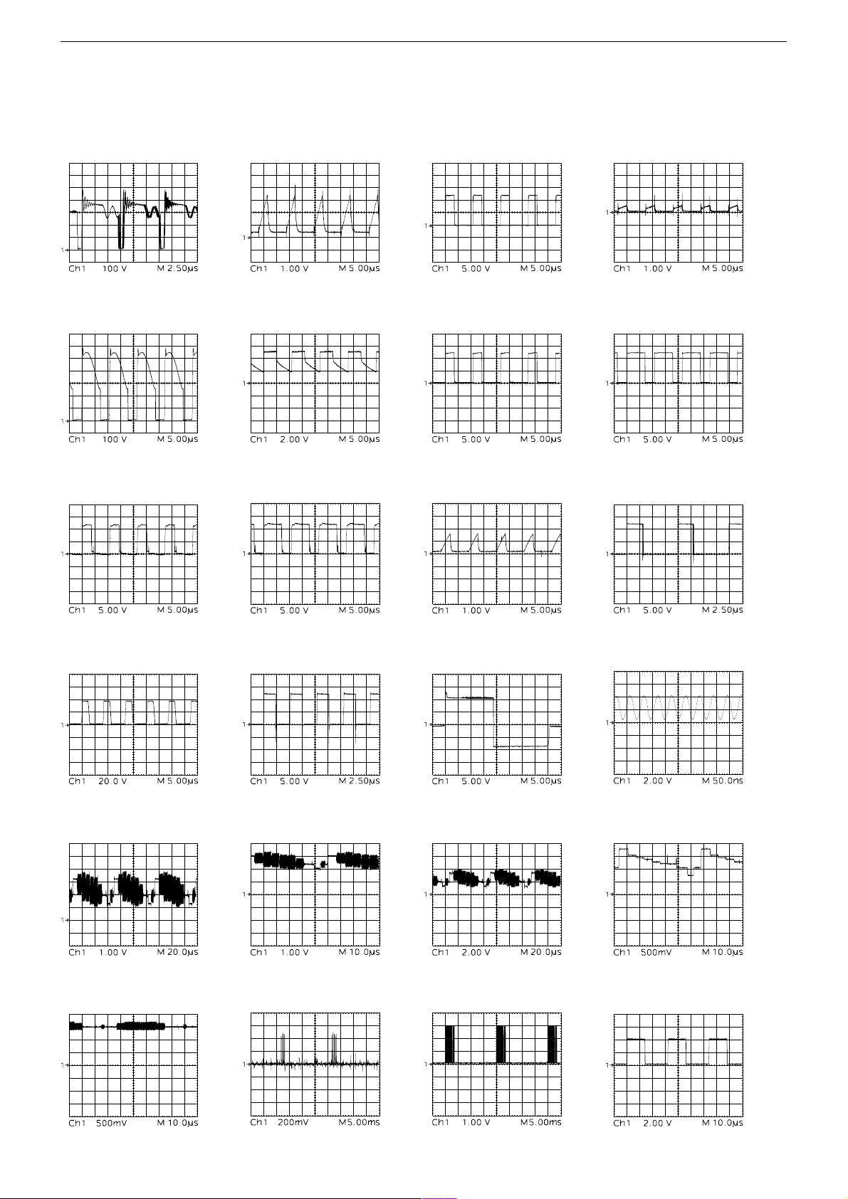
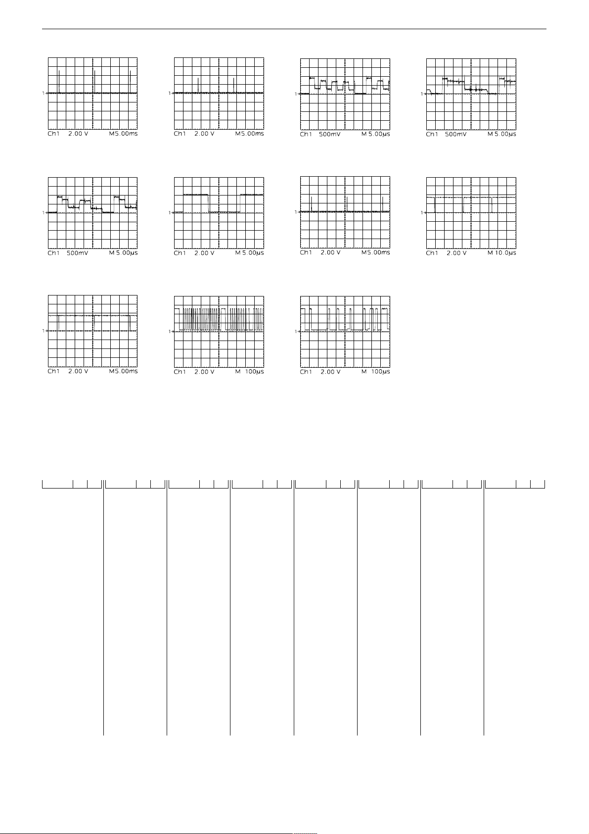
Oszillogramme / Oscillograms
1 2 3
5 6 7
9
0 !
4
8
@
# $ %
¡ ™ £
∞
§
Untertitel / Subtitle
≥
3 - 1
Untertitel / Subtitle
)
≤
•
GRUNDIG Service THARUS 51 LCD 51-9410 DOLBY
ª º
‹ ›
‡
° ·
⁄
fi
¤
fl
Chassisplatte, NF-Platte / Chassis Board, AF Board
Koordinaten für die Bauteile auf der Bestückungsseite / Coordiantes of the components on the Component Side
POS. X Y POS. X Y POS. X Y POS. X Y POS. X Y POS. X Y POS. X Y POS. X Y
BU_AV2 148 34
BU_EURO1164 36
BU_VGA_B108 39
BU_VGA_T 132 32
C29506 249 78
C29509 227 67
C29511 238 67
C29530 233 63
C29629 94 46
C31001 329 71
C31006 327 79
C31014 337 48
C31015 339 62
C32002 315 134
C32033 329 48
C32048 317 126
C33002 256 213
C33003 263 198
C33005 258 208
C33006 212 186
C33008 208 199
C33009 208 193
C40521 270 210
C40522 274 221
C40524 262 215
C41110 344 229
C41113 333 229
C41114 338 222
C41511 293 187
C41514 308 197
C41531 277 188
C41533 285 188
C43511 187 53
C43513 179 53
C43516 208 49
C43517 198 50
C43575 200 97
C43589 199 75
C60108 92 85
C60501 83 76
C60502 91 76
C60503 102 91
C60504 102 80
C60507 92 85
C60511 27 130
C60513 57 116
C60517 17 130
C60539 25 100
C60553 24 91
C60561 21 89
C60579 56 147
C60581 49 126
C60586 23 106
C60587 42 118
C60590 121 101
C61518 54 244
C61519 74 244
C61532 31 195
C61544 14 182
C61553 18 185
C61601 26 183
C61602 114 181
C61603 22 161
C61604 20 191
C61605 122 176
C61805 24 236
C61811 104 197
C61813 25 210
C61825 338 210
C61831 324 183
C61833 339 180
C61845 324 253
C61847 330 250
C62501 40 51
C62502 81 51
C62506 35 16
C62507 51 16
C70504 111 64
C70506 139 162
C70512 110 53
C70514 146 166
C70523 165 90
C70571 118 57
C70572 153 53
C70573 118 50
C72501 196 247
C72503 272 149
C72504 272 161
C72507 271 136
C72570 136 155
C72590 112 245
C72591 119 245
D60501 97 80
D60516 36 125
D60579 50 133
D60581 107 114
D60586 59 107
D60587 44 104
D60588 23 112
D61601 26 158
D61604 34 176
D61801 38 237
F32016 332 93
F32021 327 104
F32081 300 127
F70520 184 99
IC29540 236 71
IC3 209 84
IC33010 234 239
IC33080 225 218
IC40601 266 247
IC41110 346 243
IC60511 18 139
IC61604 20 171
IC61830 344 195
IC61841 316 244
IC61842 277 200
KAB1 261 239
KAB2 295 231
KH 218 32
L29730 55 234
L29731 48 234
L31014 345 43
L32001 315 158
L32051 328 162
L32094 326 149
L32095 344 149
L33001 266 187
L41111 343 249
L41112 325 223
L43613 161 47
L60579 64 105
L60585 47 113
L61511 55 206
L61512 55 201
L61514 44 181
L61523 87 181
L61601 100 189
L61801 31 226
L61807 14 236
L61811 94 203
L61825 331 211
L61831 332 179
L61833 335 193
L62501 61 63
L70445 178 76
L70501 121 76
L70502 141 165
L70511 126 96
L70513 134 170
L70531 184 90
L70532 175 90
L70543 167 69
L70562 178 67
L70566 167 80
L70590 185 169
L70592 197 165
L70594 210 160
L72503 266 157
L72504 256 156
L72590 104 242
L72592 101 240
L72602 196 234
L72612 193 226
L72622 189 219
OK60511 51 159
OK60590 22 157
Q32034 332 140
Q33046 258 195
R31001 333 79
R40521 287 208
R60511 31 136
R60522 31 102
R60575 96 107
R60577 89 113
R60578 96 102
R60579 64 148
R60585 26 119
R60590 121 94
R61514 102 175
R61515 107 163
R62501 31 72
R62502 35 54
R62503 23 62
S62501 20 32
SI40521 317 202
SI60511 42 126
SI60521 100 104
SI61801 13 210
SI61833 346 188
SI62501 16 61
ST_ASS 255 41
ST_ASS03 317 150
ST_ASS04 255 49
ST_ASS1 263 9
ST_ASS2 230 21
ST_AUX1 256 185
ST_DI3C 44 253
ST_I2C_3 184 157
ST_IRBA 320 27
ST_IRBA1 108 21
ST_KB 179 130
ST_LSL 316 225
ST_LSR 325 230
ST_NETZ 76 41
ST_PRG1 242 40
ST_RGB_1 214 65
ST_SV1 214 72
T60540 39 108
T60585 19 113
T61516 38 204
T61517 38 199
T61521 85 192
T61523 80 197
TR60500 89 139
TR60510 38 150
TR60520 13 152
TU32000 321 47
_T60579 76 106
_T61511 44 167
_T61522 81 178
3 - 2
 Loading...