

Page 1
TV Service Manual
Kundendienst/Werkstätten:
0180/52318-52*
0180/52318-46*
Telefon:
Fax:
*0,12€/Min. über Arcor
Mo.-Fr. 8.00-18.00 Uhr
LCD 1
THARUS 51
LCD 51-9310 DOLBY
GBA5200 / VNM
Zusätzlich erforderliche Unterlagen für den Komplettservice
Additionally required Service Documents for the Complete Service
Service
Manual
Sicherheit
Materialnr./Part No.
720108000000
Dieses Service Manual ist nur in Datenform verfügbar / This Service Manual is only available as data
Änderungen vorbehalten / Subject to alteration
Made by GRUNDIG in Germany • http://www.grundig.com
H-S 45 • 0203 • 720100455000
Safety
Grundig Service
Hotline Deutschland…
Technik:
TV
TV
SAT
VCR/LiveCam
HiFi/Audio
Car Audio
Telekommunikation
Planatron
Ersatzteil-Verkauf: Mo.-Fr. 8.00-19.00 Uhr
(8.00-22.00 Uhr)
…Mo.-Fr. 8.00-18.00 Uhr
0180/52318-41*
0180/52318-49*
0180/52318-48*
0180/52318-42*
0180/52318-43*
0180/52318-44*
Fax:
Telefon: 0180/52318-40*
0180/52318-45*
0180/52318-51*
0180/52318-99*
0180/52318-50*Fax:
Page 2

GRUNDIG Service THARUS 51 LCD 51-9310 DOLBY
Es gelten die Vorschriften und Sicherheitshinweise
gemäß dem Service Manual "Sicherheit", Materialnummer72010 800 0000, sowie zusätzlich die eventuell abweichenden, landesspezifischen Vorschriften!
D
Inhaltsverzeichnis
Seite
Allgemeiner Teil ................................. 1-3…1-26
Messgeräte .................................................................................. 1-3
Allgemeine Hinweise .................................................................... 1-3
Modulübersicht ............................................................................. 1-3
Technische Daten ........................................................................ 1-4
Bedienhinweise ............................................................................ 1-5
Der Grundig TV Guide ............................................................... 1-10
Service- und Sonderfunktionen .................................................. 1-21
Servicehinweise ......................................................................... 1-25
Abgleich ................................................ 2-1…2-2
The regulations and safety instructions shall be
valid as provided by the "Safety" Service Manual,
part number 72010 800 0000, as well as the
respective national deviations.
GB
Table of Contents
Page
General Section .................................. 1-3…1-26
Test Equipment ............................................................................ 1-3
General Notes .............................................................................. 1-3
Module List ................................................................................... 1-3
Technical Data ............................................................................. 1-4
Operating Hints .......................................................................... 1-15
The Grundig TV Guide (only in German) .................................. 1-10
Service and Special Functions................................................... 1-23
Service Instructions .................................................................... 1-25
Alignment.............................................. 2-3…2-4
Platinenabbildungen
und Schaltpläne ................................. 3-1…3-40
Oszillogramme ............................................................................. 3-1
Chassis LCD/ NF-Platte ............................................................... 3-3
Chassis LCD Teil 1 .................................................................... 3-12
Chassis LCD Teil 2 .................................................................... 3-16
NF-Platte 295043040100 ......................................................... 3-18
Chassis LCD Teil 3 .................................................................... 3-20
Adapter-Sound-Platte 293050191100 ....................................... 3-24
IR/BA-Platte 293050180300 .................................................... 3-24
Falconic-Platte Teil 1 295043090100 ........................................ 3-25
Falconic-Platte Teil 2 295043090100 ........................................ 3-28
M2-Platte 295043030100 ........................................................ 3-36
Ersatzteillisten ...................................... 4-1…4-3
Layout of the PCBs
and Circuit Diagrams ......................... 3-1…3-40
Oscillograms ................................................................................ 3-1
Chassis LCD AF Board ................................................................ 3-3
Chassis LCD Part 1.................................................................... 3-12
Chassis LCD Part 2.................................................................... 3-16
AF Board 295043040100 ........................................................ 3-18
Chassis LCD Part 3.................................................................... 3-20
Adapter Sound Board 293050191100 ...................................... 3-24
IR/BA Board 293050180300 ................................................... 3-24
Falconic Board Part 1 295043090100....................................... 3-25
Falconic Board Part 2 295043090100....................................... 3-28
M2 Board 295043030100 ....................................................... 3-36
Spare Parts Lists .................................. 4-1…4-3
1 - 2
Page 3

GRUNDIG Service THARUS 51 LCD 51-9310 DOLBY
Allgemeiner Teil
Messgeräte
100MHz-Oszilloskop mit Tastkopf 10:1
Digitalvoltmeter
Farbbildgenerator
Allgemeine Hinweise
Achtung: ESD-Vorschriften beachten
Wegen Veränderung des Schwerpunktes beim Abnehmen der
Rückwand bzw. Ausbau des Chassis oder Entfernen eines eventuell vorhandenen Standfußes ist das Gerät gegen Kippen zu
sichern.
Vor dem Öffnen des Gehäuses zuerst den Netzstecker ziehen!
Leitungsverlegung
Bevor Sie die Leitungen und insbesondere die Masseleitungen lösen,
muss die Leitungsverlegung zu den einzelnen Baugruppen wie z.B.
Chassis, Netzschalterplatte, Bedieneinheit, Display, Lautsprecher usw.
beachtet werden.
Nach erfolgter Reparatur ist es notwendig, die Leitungsführung wieder
in den werkseitigen Zustand zu versetzen um evtl. spätere Ausfälle
oder Störungen zu vermeiden.
Durchführen von Messungen
Bei Messungen mit dem Oszilloskop an Halbleitern sollten Sie nur
Tastköpfe mit 10:1 - Teiler verwenden. Außerdem ist zu beachten,
dass nach vorheriger Messung mit AC-Kopplung der Koppelkondensator des Oszilloskops aufgeladen sein kann. Durch die Entladung
über das Messobjekt können Bauteile beschädigt werden.
Messwerte und Oszillogramme
Bei den in den Schaltplänen und Oszillogrammen angegebenen
Messwerten handelt es sich um Näherungswerte!
DOLBY-Hinweis
DOLBY und das Doppel-D-Symbol ij sind Warenzeichen der Dolby
Laboratories Licensing Corporation.
General Section
Test Equipment
100MHz oscilloscope with 10:1 test probe
Digital voltmeter
Colour video generator
General Notes
Attention: Observe the ESD safety regulations
Because of the change of the centre of gravity when removing the
rear panel, the chassis or an existing stand, it is necessary to
protect the set from tipping.
Before opening the cabinet disconnect the mains plug!
Wiring
Before disconnecting any leads and especially the earth connecting
leads observe the way they are routed to the individual assemblies like
the chassis, mains switch panel, keyboard control panel, display,
loudspeaker and so on.
On completion of the repairs the leads must be laid out as originally
fitted at the factory to avoid later failures or disturbances.
Carrying out Measurements
When making measurements on semi-conductors with an oscilloscope, ensure that the test probe is set to 10:1 dividing factor. If the
previous measurement was made on AC input, please note that the
coupling capacitor in the oscilloscope will be charged. Discharge via
the item being checked can damage the components.
Measured Values and Oscillograms
The measured values given in the circuit diagrams and oscillograms
are approximates!
DOLBY Hint
DOLBY and the double-D symbol ij are trademarks of Dolby
Laboratories Licensing Corporation.
Modulübersicht
Module List
Bestell-Nr.
Order No.
Chassis-Nr.
Chassis No.
Tuner
IR/BA-Platte
IR/BA Board
NF-Platte
AF Board
Adapter-Sound-Platte
Adapter Sound Board
M2-Platte
M2 Board
Falconic-Platte
Falconic Board
Backlight-Inverter
Backlight Inverter
Fernbedienung TP 150 C
Remote Control TP 150 C
295045010200
293050180300
295043040100
293050191100
295043030100
295043090100
295042080100
296420660600
THARUS 51
LCD 55-9310 DOLBY
(VNM)
GBA5200
297040200200
•
•
•
•
•
•
•
•
1 - 3
Page 4
GRUNDIG Service THARUS 51 LCD 51-9310 DOLBY
Technische Daten / Technical Data
THARUS 51
LCD 51-9310 DOLBY
(VNM)
Bildröhre / Picture Tube
Sichtbares Bild
Visible picture
Bildschirmdiagonale
Screen diagonal
Elektronik / Electronic
51cm (20") 4:3 Format. Colour active Matrix TFT LCD. 0.6375mm (H) x 0.6375mm (W)
51cm
pixel pitch
Programmspeicherplätze
Programme positions
TV Guide ja / yes
Easy dialog ja / yes
Tuner
TV-Normen
TV-Standards
Stereo Systeme
Stereo systems
Videotext
Teletext
Musikleistung ohne externe LS
Music power without external LS
Anschlüsse Front / Connections Front
Kopfhörer
Headphones
Anschlüsse Rückwand / Connections Rear Panel
Euro AV 1 (schwarz/black)
PLL Frequenz Synthesizer Tuning UHF/VHF, globale Pinbelegung
PLL frequency synthesizer tuning UHF/VHF, global pinning
PAL, SECAM, NTSC 4.43MHz + 3,58MHz
Deutsch A2 / German A2 (B/G/D/K)
Nicam 5.85 (B/G, L) + 6.52MHz (I)
TOP/FLOF Level 2.5, VPS, >2000 Seiten
TOP/FLOF level 2.5, VPS, >2000 pages
Stereo 3,5mm Klinkenbuchse, Lautstärke regelbar,
individuelle Tonkanalwahl bei 2-Ton-Empfang
Stereo 3.5mm jack, adjustable volume,
individual channel selection with dual-sound broadcasts
FBAS Ein-/Ausgang, RGB Eingang, SBAS Eingang, Megalogic, Datalink für VCR
CCVS in-/output, RGB input, SCVS input, Megalogic, datalink for VCR remote control,
Fernbedienung, Decoder, 16:9 / Pin8, Nachrüstung WT-AV1
decoder capable, 16:9 / Pin 8, retrofitting WT-AV1
99 + 3 AV
B/G, I, D/K, K', M, L/L'
Stereo 3-Kanal 22W
Stereo 3-channel 22W
Für Wireless-Anschluss, Mini DIN 8-pin-Buchse, FBAS Eingang, R/L Eingang, Datalink
Euro AV 2
Euro AV 3
Standard VGA ja / yes
Interface
Netzteil / Mains Stage
Netzspannung (Regelbereich)
Mains voltage (variable)
Netzfrequenz
Mains frequency
Leistungsaufnahme
Power consumption
Standby <1W
Taken for Wireless connection, Mini DIN 8-pin socket, CCVS in, R/L-in, datalink for VCR
Für VGA-Monitor, 15-pin SubD-Buchse, 640 x 480
Taken for VGA-Monitor, 15-pin SubD socket, 640 x 480
Service-Schnittstelle (Software update/flash)
für VCR Fernbedienung
remote control
Service interface (software update/flash)
230V±15%
50 / 60Hz
ca. 40W
1 - 4
Page 5

GRUNDIG Service THARUS 51 LCD 51-9310 DOLBY
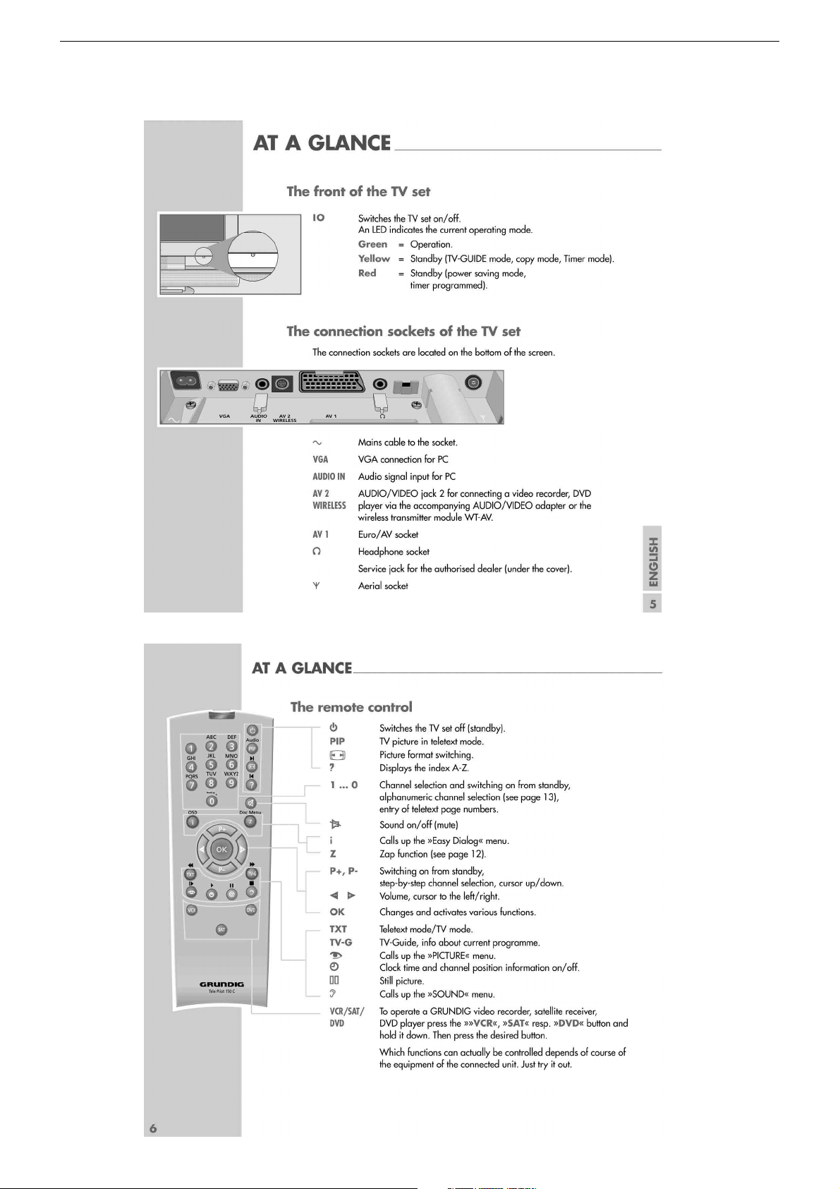
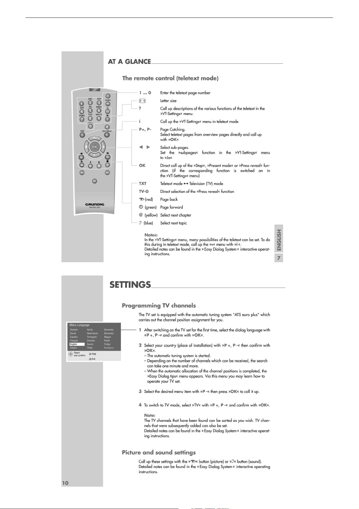
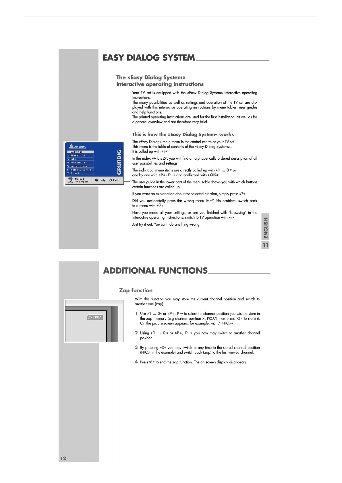
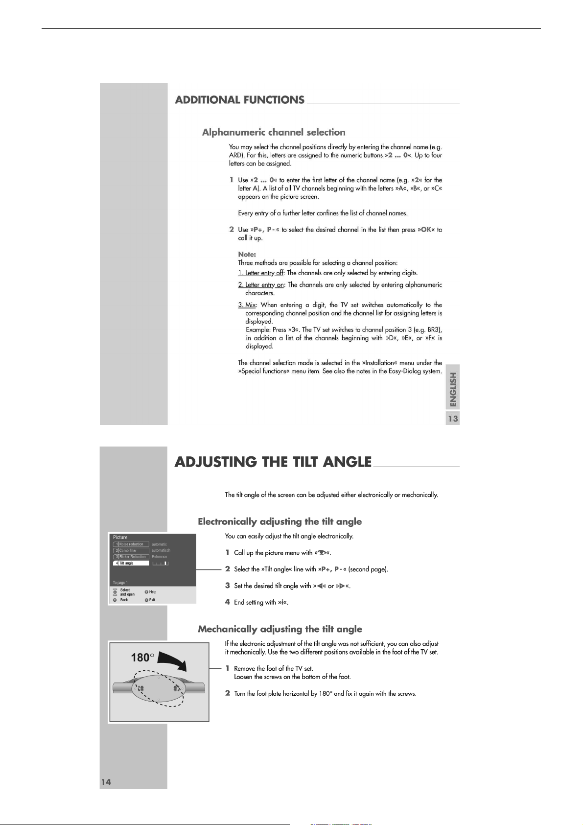
Bedienhinweise Dieses Kapitel enthält Auszüge aus der Bedienungsanleitung. Weitergehende Informationen entnehmen Sie bitte der
gerätespezifischen Bedienungsanleitung, deren Materialnummer Sie in der entsprechenden Ersatzteilliste finden.
1 - 5
Page 6

GRUNDIG Service THARUS 51 LCD 51-9310 DOLBY
1 - 6
Page 7
GRUNDIG Service THARUS 51 LCD 51-9310 DOLBY
1 - 7
Page 8

GRUNDIG Service THARUS 51 LCD 51-9310 DOLBY
1 - 8
Page 9
GRUNDIG Service THARUS 51 LCD 51-9310 DOLBY
1 - 9
Page 10
GRUNDIG Service THARUS 51 LCD 51-9310 DOLBY
1 - 10
Page 11
GRUNDIG Service THARUS 51 LCD 51-9310 DOLBY
1 - 11
Page 12

GRUNDIG Service THARUS 51 LCD 51-9310 DOLBY
1 - 12
Page 13
GRUNDIG Service THARUS 51 LCD 51-9310 DOLBY
1 - 13
Page 14
GRUNDIG Service THARUS 51 LCD 51-9310 DOLBY
1 - 14
Page 15
GRUNDIG Service THARUS 51 LCD 51-9310 DOLBY
Operating Hints This chapter contains excerpts from the operating instructions. For further particulars please refer to the appropriate user
instructions the part number of which is indicated in the relevant spare parts list.
1 - 15
Page 16
GRUNDIG Service THARUS 51 LCD 51-9310 DOLBY
1 - 16
Page 17
GRUNDIG Service THARUS 51 LCD 51-9310 DOLBY
1 - 17
Page 18
GRUNDIG Service THARUS 51 LCD 51-9310 DOLBY
1 - 18
Page 19

GRUNDIG Service THARUS 51 LCD 51-9310 DOLBY
1 - 19
Page 20

GRUNDIG Service THARUS 51 LCD 51-9310 DOLBY
1 - 20
Page 21

GRUNDIG Service THARUS 51 LCD 51-9310 DOLBY
D
Service- und Sonderfunktionen
Aufruf des Service-Menüs: Taste "Ǻ" (EASY DIALOG)
Aufruf der Dialogzeile: Tasten "P+" oder "P-" –> "OK"
Einstellung in der Dialogzeile ändern : Tasten "L+" oder "L-" –> "OK"
Zurück ins vorherige Menü: "blaue" Taste
Beenden des Menüs: Taste "Ǻ"
Servicemenü für Händler (Codezahl): "8500"
1. Einschaltfunktionen
1.1 ATS-Reset
Netzschalter "EIN" mit gedrückter Fernbedientaste "L+".
- Gerät wird mit Analog-Grundwerten geladen.
- ATS-Bit wird gesetzt. Diese Option löst beim nächsten Einschalten
das ATS euro plus aus. Die bisherige Programmbelegung (Senderkanäle) wird gelöscht.
1.2 Programmsperre (Kindersicherung)
Die Tastenfolge "7 0 3 8 5 8 0" hebt die persönliche Kennzahl auf.
1.3 Software-Versionsnummer
Das Menü "EASY DIALOG" aufrufen. Die "grüne" Taste zeigt die
Software-Versionsnummer an.
1.4 Flashprogrammierung
Benötigtes Equipment
Flash-Programmer F-Prog 1 / ab Version 2.0 oder
Service Toolbox Materialnummer 772004001200.
Erforderliche Hardware (Minimum)
Pentium-PC, Microsoft Windows 95
- freier Arbeitsspeicher 32MB
- CD-ROM-Laufwerk
- serielle Schnittstelle
- Internet-Zugang
Abrufen der aktuellen Gerätesoftware
Die Software ist in einem mit Grundig-Kundennummer und Passwort
geschützten Bereich im Internet unter Grundig/Partnerweb (B2B)
abrufbar.
Hinweis zum Abrufen der Software:
- Internet-Browser starten.
- http://partnerweb.grundig.de eingeben und starten.
- Folgen Sie der Menüführung unter "Kundendienst –> SoftwareDownload".
1.5 Direkte Display-Typ-Einstellung
Ist die Menüdarstellung auf Grund falscher Display-Typ-Einstellung
nicht mehr möglich, können Sie mit "Short-cuts" die korrekte Einstellung vornehmen.
Vor und nach der Direkteingabe muss das Gerät aus- und wieder
eingeschaltet werden!
Tasten "Ǻ", "rot" und Ziffer stellt den gewünschten Display-Typ im
Service ein. Folgende Ziffern geben den jeweiligen Display-Typ an:
1 LG 20" 4:3
2 NEC 20" 4:3
3 Samsung 22" 16:9
4 NEC 23" 16:9
5 LCD 30" 16:9
2. Sonderfunktionen im Menü "Installation"
2.1 Buchstaben-Eingabe
Das Menü "Buchstaben-Eingabe" über "EASY DIALOG" –> "Installation" –> "Sonderfunktionen" aufrufen.
Sie können die Buchstaben-Eingabe für die Programmwahl zwischen
"aus", "ein" und "mix" wählen.
2.2 "Tonskala" sichtbar oder unsichtbar für alle Programme
Das Menü "Tonskala" über "EASY DIALOG" –> "Installation" –>
"Sonderfunktionen" aufrufen.
Bei "aus" erscheint keine Balkenanzeige für die Lautstärke.
2.3 Einschalten mit Programm "1" oder "automatisch"
Das Menü "Einschalten" über "EASY DIALOG" –> "Installation" –>
"Sonderfunktionen" aufrufen.
Auf "Programmplatz 1" oder "automatisch" stellen.
Bei "automatisch" wird der beim Ausschalten eingestellte Programmplatz beim Einschalten wieder aufgerufen (Last station memory).
2.4 "Megalogic Info" (nur wenn Megalogic-Gerät erkannt wurde).
Das Menü "Megalogic Info" über "EASY DIALOG" –> "Installation" –>
"Sonderfunktionen" aufrufen.
Die Megalogic-Steuerung kann auf "ein" bzw. "aus" geschaltet werden.
2.5 Statusanzeige
Das Menü "Statusanzeige" über "EASY DIALOG" –> "Installation" –>
"Sonderfunktionen" aufrufen.
Sie können wählen an welcher Position ("oben" oder "unten") die
Information über Tonart und Bildformat eingeblendet wird.
Bei "aus" wird nach Progammwechsel keine Information eingeblendet.
2.6 Automatische Lautstärke
Das Menü "Autom. Lautstärke" über "EASY DIALOG" –> "Installation"
–> "Sonderfunktionen" aufrufen.
In Stellung "ein" regelt der Ton-IC bei erhöhter Senderlautstärke (z. B.
erhöhter HUB bei der Werbung) die Lautstärke intern auf den normalen Wert zurück.
2.7 Rauschreduktion P1-P…
Das Menü "Rauschreduktion P1-P…" über "EASY DIALOG" –> "Installation" –> "Sonderfunktionen" aufrufen. Sie können die Rauschreduktion für die Programme 1-P… auf "aus", "gering" oder "automatisch" stellen.
Bei "manuell" wird angezeigt, dass ein oder mehrere Programme
unterschiedliche Einstellungen haben.
2.8 Bildschärfe P1-P…
Das Menü "Bildschärfe P1-P…" über "EASY DIALOG" –> "Installation"
–> "Sonderfunktionen" aufrufen.
Die Bildschärfe wird für alle Programme eingestellt.
2.9 Farbdeckung
Das Menü "Farbdeckung" über "EASY DIALOG" –> "Installation" –>
"Sonderfunktionen" aufrufen.
Die Farbdeckung (Luma-Delay) wird programmplatzbezogen eingestellt.
3. Service-Einstellungen für den Fachhandel
3.1 Bildeinstellungen
3.1.1 Weißabgleich
Das Menü "Weißabgleich" über "EASY DIALOG" –> "Installation" –>
"Servicemenü für Händler" –> "8500" –> "Bildeinstellungen" aufrufen.
Den Wert für "rot", "grün" und "blau" so einstellen, dass es weiß ergibt.
(siehe Abgleich Punkt 5).
Hinweis:
Nach Neuaufruf des Menüs ist der Wert der größten Komponente
immer 511, die anderen Werte werden umgerechnet.
3.1.2 Schwarzwertabgleich
Gerät auf AV-Stellung (Schwarzbild)
Das Menü "Schwarzwertabgleich" über "EASY DIALOG" –> "Installation" –> "Servicemenü für Händler" –> "8500" –> "Bildeinstellungen"
aufrufen.
Den Wert für "rot", "grün" und "blau" so einstellen, dass der Übergang
der Farbtreppe (Testbild) für alle 3 Farben an der gleichen Stelle liegt
(R,G,B gerade sichtbar). Dabei sollen die Reglerwerte für die Komponenten möglichst nahe am Vorgabewert 248 bleiben.
Offset so einstellen, dass das Farbfenster innerhalb des mittleren
Rahmen ist.
(siehe Abgleich Punkt 6).
3.1.3 Blauen Bildschirmhintergrund ein/ausschalten
Das Menü "Blauer Bildschirm" über "EASY DIALOG" –> "Installation"
–> "Servicemenü für Händler" –> "8500" –> "Bildeinstellungen" aufrufen.
Auf "ein" oder "aus" stellen.
1 - 21
Page 22

GRUNDIG Service THARUS 51 LCD 51-9310 DOLBY
3.2 Hardware-Ausstattung
3.2.1 Displaytyp
Das Menü "Bildröhrentyp" über "EASY DIALOG" –> "Installation" –>
"Servicemenü für Händler" –> Kennzahl "8500" –> "HardwareAustattung" aufrufen.
Bildröhrentyp/Displaytyp einstellen (siehe Abgleich Punkt 1).
3.2.2 ZF-Typ
Das Menü "ZF-Typ" über "EASY DIALOG" –> "Installation" –>
"Servicemenü für Händler" –> Kennzahl "8500" –> "HardwareAustattung" aufrufen.
Nach Wechsel des NVM muss der ZF-Typ eingestellt werden:
Inland-Geräte: Inland
Multi 8-Geräte: Multi 8
Multi 9-Geräte: Multi 9 (siehe Abgleich Punkt 2).
3.2.3 Tuner-Typ
Das Menü "Terr. Tuner" über "EASY DIALOG" –> "Installation" –>
"Servicemenü für Händler" –> Kennzahl "8500" –> "HardwareAustattung" aufrufen.
Auf im Gerät eingebauten Tuner einstellen.
3.2.4 Fernbedienung
Das Menü "Fernbedienung" über "EASY DIALOG" –> "Installation" –>
"Servicemenü für Händler" –> Kennzahl "8500" –> "HardwareAustattung" aufrufen.
Auf "TP150" oder "PR11" einstellen.
3.2.5 Subwoofer
Das Menü "Subwoofer" über "EASY DIALOG" –> "Installation" –>
"Servicemenü für Händler" –> Kennzahl "8500" –> "HardwareAustattung" aufrufen.
Auf "ja" oder "nein" stellen.
3.2.6 Front-LED
Das Menü "Front-LED" über "EASY DIALOG" –> "Installation" –>
"Servicemenü für Händler" –> Kennzahl "8500" –> "HardwareAustattung" aufrufen.
Auf "3 Colors" oder "1 Color" stellen.
3.3 Sonderfunktionen
3.3.1 Watchdog On/Off
Das Menü "Watchdog" über "EASY DIALOG" –> "Installation" –>
"Servicemenü für Händler" –> "8500" –> "Sonderfunktionen" aufrufen.
Wird der Watchdogtimer nicht in regelmäßigen Zeitabständen zurückgesetzt, wird ein Neustart ausgelöst.
Watchdog auf "aus" oder "ein" schalten.
3.3.2 IR-Dataprogrammer
Das Menü "IR-Dataprogrammer" über "EASY DIALOG" –> "Installation"
–> "Servicemenü für Händler" –> "8500" –> "Sonderfunktionen" aufrufen. Mit der Taste "OK" können mit dem IR-Dataprogrammer 2 max. 99
Programmplätze mit Daten für Kanal, Norm, Peri, 6-stellige Sendereinblendung, Finetuning-Mitte und Lautstärke-Offset "0" abgespeichert
werden.
3.3.3 AGC-Einstellung
Das Menü "AGC-Einstellung" über "EASY DIALOG" –> "Installation"
–> "Servicemenü für Händler" –> Kennzahl "8500" –> "Sonderfunktionen" aufrufen.
Wert so einstellen, dass das Bild gerade rauschfrei ist.
(siehe Abgleich Punkt 4).
3.3.4 TV-Guide-Flash löschen
Das Menü "TV-Guide-Flash löschen" über "EASY DIALOG" –> "Installation" –> "Servicemenü für Händler" –> Kennzahl "8500" –> "Sonderfunktionen" aufrufen.
Nach Drücken der Taste "OK" wird das TV-Guide-Flash in einen
definierten Zustand versetzt. Ungültige und fehlerhafte Werte werden
zurückgesetzt.
3.3.5 Videotext-Level-2.5-Unterstützung
Das Menü "Videotext Level 2.5" über "EASY DIALOG" –> "Installation"
–> "Servicemenü für Händler" –> Kennzahl "8500" –> "Sonderfunktionen" aufrufen.
Auf "ja" oder "nein" stellen.
4. Ton-Einstellungen
Mit "blauer" Taste das Menü "Ton" aufrufen.
Im Menü "Voreinstellungen" sind die Einstellungen "Sprache", "Musik"
oder "manuell" anwählbar.
Die "manuell"-Einstellung lässt eine Einstellung des Klanges zu. In den
anderen Einstellungen sind bestimmte Werte fest vorgegeben.
5. Bild-Einstellungen
Mit roter Taste das Menü "Bild" aufrufen.
- Im Menü "Voreinstellungen" sind die Einstellungen "Am Tag", "Am
Abend" und "manuell" anwählbar.
Die "manuell"-Einstellung lässt eine Regulierung von Kontrast,
Schärfe zu. In den anderen Einstellungen sind bestimmte Werte fest
vorgegeben.
- Im Menü "Neigungswinkel" kann Helligkeit/Kontrast je nach
Betrachtungswinkel eingestellt werden.
6. Einstellungen über die Senderbelegung
6.1 Zwangseinstellungen im Programm-Mode
Das Menü "Tonkanal" über "EASY DIALOG" –> "Programmtabelle" –>
"grüne Taste" –> "Kanaleinstellungen ändern" aufrufen.
Sie können zwischen "autom.", "Mono", "Mono B" und "Mono C"
wählen.
Mono B = Orginalton
Mono C = Bei Digitalem Ton-Empfang (Nicam).
7. Werkseinstellung
Tasten "Ǻ", "rot" und OK ruft die Werkseinstellwerte auf.
1 - 22
Page 23

GRUNDIG Service THARUS 51 LCD 51-9310 DOLBY
GB
Service and Special Functions
Call up the Service Menu: Button "Ǻ" (EASY DIALOG)
Call up the dialogue line: Buttons "P+" or "P-" –> "OK"
Changing the setting in the dialogue line: Buttons "L+" or "L-" –> "OK"
Back to previous menu: "Blue" button
Exit menu: "Ǻ" button
Service menu for retailer (code number) 8500
1. Switching-on Options
1.1 ATS Reset
Press mains button "ON " while holding down the "L+" button on the
remote control.
- The basic analogue values are loaded.
- The ATS bit is set. When switching on the next time, this option
releases the ATS euro plus function. The current programme
allocation (channels) is cleared.
1.2 Electronic Programme Lock (parental lock)
Enter the key sequence "7 0 3 8 5 8 0" to cancel your personal code
number.
1.3 Software Version Number
Call up the "EASY DIALOG" menu. Pressing the green button indicates the software version number.
1.4 Flash Programming
Required equipment
Flash programmer F-Prog 1 / from version 2.0 on or
Service Toolbox part number 772004001200.
Required hardware
Pentium-PC, Microsoft Windows 95
- Free memory of 32MB
- CD-ROM drive
- COM port
- Internet access
Calling up the current TV software
The software can be called up from an area of the Grundig partnerweb
(B2B), protected via a Grundig customer number and a password.
Note to downloading the software:
- Start the Internet Browser.
- Input the address http://partnerweb.grundig.com and start.
- Follow the menu guide in "Service -> Software Download".
1.5 Direct Display Type Adjustment
If the menus can not be displayed any longer due to an incorrect display
type adjustment, you can carry out the correct adjustment with the help
of key short cuts.
Before and after the direct entry, the unit must be switched off and on
again!
The "Ǻ", "red" and numeric keys select the desired display type in the
service mode. The following digits indicate the display types:
1 LG 20" 4:3
2 NEC 20" 4:3
3 Samsung 22" 16:9
4 NEC 23" 16:9
5 LCD 30" 16:9
2. Special Functions in the "Installation" Menu
2.1 Entry of Letters
Call up the "Letter entry" menu via "EASY DIALOG" –> "Installation"
–> "Special functions".
You may select between "off", "on" and "mix" for the programme
selection letter entry.
2.2 Visible or Unvisible "Sound scale" for all Programmes
Call up the "Sound scale" menu via "EASY DIALOG" –> "Installation"
–> "Special functions".
With "off" selected, no volume bar is displayed.
2.3 Switching on with Programme "1" or automatically
Call up the "Switch on" menu via "EASY DIALOG" –> "Installation" –
> "Special functions" .
Set the option "Preset 1" or "Automatic".
With the "automatc" setting, the programme position selected when
switching off is selected again when switching the set on again (Last
station memory).
2.4 "Megalogic Info" (only if a connected Megalogic set is identified)
Call up the "Megalogic info" menu via "EASY DIALOG" –>
"Installation" –> "Special functions".
The Megalogic control can be switched to "on" or "off".
2.5 Status Display
Call up the "Status Display" menu via "EASY DIALOG" –>
"Installation" –> "Special functions".
You may select the position (top or bottom) where the information
about the sound mode and the picture format is displayed.
With the "off" option, no information is displayed when changing the
programme.
2.6 Automatic Volume
Call up the "Automatic volume" menu via "EASY DIALOG" –>
"Installation" –> "Special functions".
In the "ON" position, the sound IC regulates the volume internally to
the normal value (e.g. increased deviation in the case of advertising).
2.7 Noise Reduction P1-P…
Call up the "Noise reduction P1-P…" menu via "EASY DIALOG" –>
"Installation" –> "Special functions. For the programmes 1-P… you
may set the noise reduction to "off", "low" or "automatic".
"Manual" indicates that one or several programmes have different
settings.
2.8 Picture Sharpness P1-P…
Call up the "Sharpness P1-P…" menu via "EASY DIALOG" –>
"Installation" –> "Special functions".
The picture sharpness is set for all programmes.
2.9 Colour Match
Call up the "Colour match" menu via "EASY DIALOG" –> "Installation"
–> "Special functions".
The colour match (luma delay) is set for every programme.
3. Service Settings for the Retailer
3.1 Picture Settings
3.1.1 White Balance
Call up the "White balance" menu via "EASY DIALOG" –> "Installation"
–> "Dealer service menu" –> Code number "8500" –> "Picture settings".
Adjust the values for "red", "green" and "blue" so that a white picture
is obtained. (See Alignment, Point 5).
Note:
When calling up the menus again, the value of the largest component
is always 511, the other values are converted.
3.1.2 Black Level Balance
Call up the "Black level balance" menu via "EASY DIALOG" –>
"Installation" –> "Dealer service menu" –> Code number "8500" –>
"Picture settings".
Select the AV position (black picture) on the TV set.
Adjust the "red", "green" and "blue" values in such a way that the
transition of the colour scale (test pattern) is at the same place for all
3 colours (R,G,B just visible). The control values for the components
should remain as close as possible to the given value 248.
Adjust the offset in such a way that the colour window is located inside
the centre frame (see Alignment, Point 6).
3.1.3 Switching the Blue Screen Background On and Off
Call up the "Blue screen" menu via "EASY DIALOG" –> "Installation"
–> "Dealer service menu" –> Code number "8500" –> "Picture settings".
Select "on" or "off".
1 - 23
Page 24

GRUNDIG Service THARUS 51 LCD 51-9310 DOLBY
3.2 Hardware Equipment
3.2.1 Display type
Call up the "Tube type" menu via "EASY DIALOG" –>
"Installation" –> "Only for the retailer" –> Code number "8500" –>
"Hardware equipment".
Select the appropriate picture tube type / display type.
3.2.2 IF Type
Call up the "IF Type" menu via "EASY DIALOG" –> "Installation" –>
"Only for the retailer" –> Code number "8500" –> "Hardware equipment".
After replacing the NVM, it is necessary to adjust the IF type:
Inland sets: National
Multi-8 sets: Multi 8
Multi-9 sets: Multi 9
(see Alignment, Point 2).
3.2.3 Tuner Type
Call up the "Terrestrial tuner" menu via "EASY DIALOG" –> "Installation" –> "Only for the retailer" –> Code number "8500" –> "Hardware
equipment".
Select the appropriate tuner type.
3.2.4 Remote Control
Call up the "Remote control" menu via "EASY DIALOG" –> "Installation" –> "Only for the retailer" –> Code number "8500" –> "Hardware
equipment".
Select "TP150" or "PR11".
3.2.5 Subwoofer
Call up the "Subwoofer" menu via "EASY DIALOG" –> "Installation"
–> "Only for the retailer" –> Code number "8500" –> "Hardware
equipment".
Select "yes" or "no".
3.2.6 Front-LED
Call up the "Front-LED" menu via "EASY DIALOG" –> "Installation"
–> "Only for the retailer" –> Code number "8500" –> "Hardware
equipment".
Select "3 Colors" or "1 Color".
4. Sound Settings
Press the "blue" button to call up the "Sound" menu.
The settings "Speech", "Music" or "manual" can be selected in the "Defaults"
menu.
The "Manual" setting allows you to adjust the sound to suit your taste. For the
other settings, specific values are preprogrammed.
5. Picture Settings
Press the "red" button to call up the "Picture" menu.
- In the "Defaults" menu, the settings "Day", "Night", and "Manual"
can be selected.
With the "Manual" option, you may set the contrast and the picture
sharpness. For the other settings, specific values are preprogrammed.
- In the "Tilt angle" menu brightness/contrast can be adjusted according to the viewing angle.
6. Settings via the Channel Allocation
6.1 Forced Settings in Programme Mode
Call up the "Sound channel" menu via "EASY DIALOG" –>
"Preset List" –> "green button" –> "Edit channel settings".
You may select between "Automatic", "Mono", "Mono B" and
"Mono C".
Mono B = Original sound track
Mono C = For digital sound reception (Nicam).
7. Factory Settings
Press the "Ǻ", "red" and OK buttons to call up the factory settings.
3.3 Special Functions
3.3.1 Watchdog On/Off
Call up the "Watchdog" menu via "EASY DIALOG" –> "Installation"
–> "Dealer service menu" –> Code number "8500" –> "Special
functions".
If the Watchdog timer is not reset in regular intervals, a new start is
initialized.
Set the Watchdog to "off" or "on".
3.3.2 IR Data Programmer
Call up the "IR-Data programmer" menu via "EASY DIALOG" –>
"Installation" –> "Dealer service menu" –> Code number "8500" –>
"Special functions". Using the "OK" button, it is possible to store up to
99 programme positions with data for channel, TV standard, Peri, 6position station name, centre fine tuning, and "0" volume offset, with
the help of the IR data programmer.
3.3.3 AGC Setting
Feed in a standard channel raster without finetuning in band 1.
Call up the "AGC setting" menu via "EASY DIALOG" –> "Installation"
–> "Dealer service menu" –> Code number "8500" –> "Special
functions".
Adjust the value so that the picture is just free of noise.
(see Alignment, Point 4).
3.3.4 Cancel EPG Flash
Call up the "Cancel EPG flash" menu via "EASY DIALOG" –> "Installation" –> "Dealer service menu" –> Code number "8500" –> "Special
functions".
Pressing the "OK" button will clear the EPG Flash.
3.3.5 Teletext Level 2.5 Support
Call up the "Teletext level 2.5" menu via "EASY DIALOG" –>
"Installation" –> "Dealer service menu" –> Code number "8500" –>
"Special functions".
Select "yes" or "no".
1 - 24
Page 25

GRUNDIG Service THARUS 51 LCD 51-9310 DOLBY
Servicehinweise
Leitungsverlegung
Nach erfolgter Reparatur ist es notwendig, die Leitungsführung wieder
in den werkseitigen Zustand zu versetzen um evtl. spätere Ausfälle
oder Störungen zu vermeiden.
1. Öffnen des Gerätes
– Vor dem Öffnen des Gerätes dieses vom Netz trennen.
– Sicherheitshinweise beachten (siehe Service Manual "Sicherheit",
Materialnummer 720108000000).
1.1 Rückwand
– Schraube A (Fig. 1) und 2 Schrauben B (Fig. 1) herausdrehen.
– Geräterückwand an den beiden Stellen C (Fig. 1) leicht drücken
und die Geräterückwand abnehmen.
2. Ausbauhinweise
Hinweis: TV-Gerät auf eine weiche kratzfreie Unterlage legen.
2.1 Soundsystem
–
2 Schrauben N (Fig. 4) und 4 Schrauben F (Fig. 3) herausdrehen.
– Soundsystem nach untern abziehen.
2.2 Bügel
– 4 Schrauben D (Fig. 2) herausdrehen.
– Bügel abnehmen.
2.3 Chassisplatte
– Soundsystem ausbauen (Punkt 2.1).
– Bügel ausbauen (Punkt 2.2).
– Klammer L (Fig 3) abnehmen
– 2 Schrauben G (Fig. 3) und
–
Buchsenabdeckung abnehmen.
– 2 Schrauben H (Fig. 3)und 8 Schrauben I (Fig. 3) herausdrehen.
–
Chassisplatte herausnehmen und gegebenenfalls Steckverbindungen lösen.
2.4 Backlight-Inverter
– 3 Schrauben K (Fig. 3) herausdrehen.
– Backlight-Inverter abnehmen und gegebenenfalls Steck-
verbindungen lösen.
2.5 Display
– 4 Schrauben J (Fig. 3) herausdrehen.
– Trägerblech abnehmen.
– Display herausnehmen.
– Gegebenenfalls Steckverbindungen lösen.
2.6 Hintergrundbeleuchtung
– Display ausbauen (Punkt 2.5).
– Schrauben L (Fig. 5) von der Frontseite herausdrehen.
– Anschlussleitungen der Hintergrundbeleuchtung ausfädeln.
– Hintergrundbeleuchtungen (Leuchtstäbe) vorsichtig herausziehen.
3. Wichtige Masseverbindungen!
Beim Zusammenbau des Gerätes ist darauf zu achten, dass die
Masseverbindungen zwischen den einzelnen Baugruppen gewähr-
leistet sind.
Des Weiteren ist darauf zu achten, dass das Gerät entsprechend dem
werkseitigen Zustand zusammengebaut ist um spätere Störungen
oder Ausfälle zu vermeiden.
2 Stehbolzen E (Fig. 2) herausdrehen.
Service Instructions
Wiring
On completion of the repairs the leads must be laid out as originally
fitted at the factory to avoid later failures or disturbances.
1. Opening the Set
– Disconnect the set from the mains before opening it.
– Observe the safety instructions (see Service Manual "Safety", part
number 720108000000)
1.1 Rear Panel
– Undo the screw A (Fig. 1) and the 2 screws B (Fig. 1).
– Slightly press on the rear panel at the two points C (Fig. 1), and
then remove the rear panel.
2. Disassembly Instructions
Note: place the TV set on a soft and non scratching pad.
2.1 Sound System
–
Undo the 2 screws N (Fig. 4) and the 4 screws F (Fig. 3).
– Pull the Sound system off in downward direction.
2.2 Bracket
– Undo the 4 screws D (Fig. 2).
– Remove the bracket.
2.3 Chassis Board
– Remove the Sound system (Point 2.1).
– Remove the bracket (Point 2.2).
– Remove the clamp L (Fig. 3).
– Undo the 2 screws G (Fig. 3) and the
–
Remove the sockets cover.
– Undo the 2 screws H (Fig. 3) and the 8 screws I (Fig. 3).
–
Remove the chassis board. For this, disengage the connectors if
necessary.
2.4 Backlight Inverter
– Undo the 3 screws K (Fig. 3).
– Remove the Backlight Inverter.
necessary.
2.5 Display
– Undo the 4 screws J (Fig. 3).
– Remove the sheet metal holder.
– Remove the display.
– Disengage the connectors if necessary.
2.6 Background Illumination
– Remove the display (Point 2.5).
– Undo the screws L (Fig. 5) on the front panel.
– Unthread the connecting leads of the background illumination.
– Carefully pull out the background illumination (fluorescent tubes).
3. WARNING: Chassis Connections!
When reassembling the TV set, make sure that the ground connections
between the individual componentries are restored.
In addition, make sure that the set is reassembled as originally at the
factory to avoid later disturbances and failures.
2 distance bolts E (Fig. 2).
For this, disengage the connectors if
1 - 25
Page 26

GRUNDIG Service THARUS 51 LCD 51-9310 DOLBY
C
A
B
C
Fig. 1 Fig. 2
H
L
D
E
J
Fig. 3
I
I
K
J
M
N
F
GG
Fig. 4
O
O
Fig. 5 Fig. 6
1 - 26
P
P
Page 27

GRUNDIG Service THARUS 51 LCD 51-9310 DOLBY
Abgleich
Alle nicht beschriebenen Einstellelemente sind werkseitig abgeglichen und dürfen im Servicefall nicht verstellt werden.
Aufruf des Service-Menüs: Taste "Ǻ" (EASY DIALOG)
Aufruf der Dialogzeile: Tasten "P+" oder "P-" –> "OK"
Einstellung in der Dialogzeile ändern: Tasten "L+" oder "L-" –> "OK"
Zurück ins vorherige Menü: "blaue" Taste
Beenden des Menüs: Taste "Ǻ"
Servicemenü für Händler (Codezahl): "8500"
Messgeräte: 100MHz Oszilloskop mit Tastkopf 10:1, Digitalvoltmeter, Farbbildgenerator.
Abgleich Vorbereitung Abgleichvorgang
1. Displaytyp
2. ZF-Typ
3. Terr. Tuner-Typ
4. Tuner-AGC
5. Weißwert
Das Menü "Bildröhrentyp" über "EASY DIALOG" –>
"Installation" –> "Servicemenü für Händler" –> "8500" –>
"Hardware-Einstellungen" aufrufen.
Das Menü "ZF-Typ" über "EASY DIALOG" –> "Installation"
–> "Servicemenü für Händler" –> "8500" –> "HardwareEinstellungen" aufrufen.
Das Menü "Terr. Tuner" über "EASY DIALOG" –>
"Installation" –> "Servicemenü für Händler" –> Kennzahl
"8500" –> "Hardware-Einstellungen" aufrufen.
100MHz-Oszilloskop an Tunerkontakt 10 oder 11 gegen
Tunermasse anschließen.
Testbild (mit abgeschaltetem Tonträger) über die Antenne
einspeisen, 70…80dBµV.
Das Menü "AGC-Einstellung" über "EASY DIALOG " –>
"Installation" –> "Servicemenü für Händler" –> "8500" –>
"Sonderfunktionen" aufrufen.
Grautreppe mit Burst einspeisen.
Weißbalance: Mittenstellung
Kontrast: Maximum
Farbkontrast: Mittelwert
Bildschirmhelligkeit: Mittelwert
Neigungswinkel: Mittelwert
Das Menü "Weißabgleich" über "EASY DIALOG" –>
"Installation" –> "Servicemenü für Händler" –> "8500" –>
"Bildeinstellungen" aufrufen.
Auf eingebautes Display einstellen:
1 LG 20" 4:3
2 NEC 20" 4:3
3 Samsung 22" 16:9
4 NEC 23" 16:9
5 LCD 30" 16:9
Auf im Gerät eingebauten ZF-Typ einstellen.
Inland, Multi 8 oder Multi 9.
Auf den im Gerät eingebauten Tuner einstellen.
Auf 300-350mVss einstellen.
Die Werte für rot, grün und blau so einstellen, dass das
Bild unbunt wird.
Hinweis:
Nach der Einstellung und verlassen des Menüs ist der Wert
der grössten Komponente immer 511, die anderen Werte
werden umgerechnet.
6. Schwarzwert
7. Bildgeometrie
Das Menü "Schwarzwertabgleich" über "EASY DIALOG"
–> "Installation" –> "Servicemenü für Händler" –> "8500"
–> "Bildeinstellungen" aufrufen.
Gerät auf AV-Stellung (Schwarzbild)
Das Menü "Bildgeometrie" über "EASY DIALOG" –> "Installation" –> "Servicemenü für Händler" –> "8500" aufrufen.
Geometrietestbild einspeisen.
Reset: Das Feld "Reset" enthält:
- entweder die optimalen Bildgeometriedaten des Gerätes
aus der Fertigung.
- oder einen mittleren Datensatz aus dem ROM, wenn das
Gerät mit dem Notdatensatz gestartet wurde.
Nach einem Fehlabgleich können Sie diese Grundwerte
jederzeit wieder laden:
Das Menü "Reset" über "EASY DIALOG " –> "Installation"
–> "Servicemenü für Händler" –> "8500" –> Bildgeometrie
aufrufen.
2 - 1
Den Wert für "rot", "grün" und "blau" so einstellen, dass der
Übergang der Farbtreppe (Testbild) für alle 3 Farben an
der gleichen Stelle liegt (R,G,B gerade sichtbar).
Dabei sollen die Reglerwerte für die Komponenten möglichst
nahe am Vorgabewert 248 bleiben.
Offset so einstellen, dass das Farbfenster innerhalb des
mittleren Rahmens ist.
Mit Bildhöhe, Vert. Pos., Horiz. Pos.,Bildbreite das Testbild
in Bildschirmmitte bringen und symmetrische Beschreibung des Displays einstellen.
Speichern:
Der eingestellte Wert wird durch Drücken der "gelben"
Taste gespeichert.
Die Bildgeometrie stellt sich nach jedem Einschalten auf
den zuletzt abgespeicherten Wert ein.
Page 28

GRUNDIG Service THARUS 51 LCD 51-9310 DOLBY
Abgleich Vorbereitung Abgleichvorgang
Bildgeometrie
VGA
Gerät in Programmstellung "AV3" schalten und Geometriebild über die VGA-Buchse einspeisen.
Das Menü "Reset" über "EASY DIALOG " –> "Installation"
–> "Servicemenü für Händler" –> "8500" –> Bildgeometrie
aufrufen.
Mit Vert. Pos., Horiz. Pos., Bildbreite das Testbild in
Bildschirmmitte bringen und symmetrische Beschreibung
des Displays einstellen.
Speichern:
Der eingestellte Wert wird durch Drücken der "gelben"
Taste gespeichert.
Die Bildgeometrie stellt sich nach jedem Einschalten auf
den zuletzt abgespeicherten Wert ein.
2 - 2
Page 29

GRUNDIG Service THARUS 51 LCD 51-9310 DOLBY
Alignment
All adjustment controls not mentioned in this description are adjusted during production and must not be re-adjusted in the case of repairs.
Call up the service menu: Button "Ǻ" (EASY DIALOG)
Call up the dialogue line: Buttons "P+" or "P-" –> "OK"
Change setting in the dialogue line: Buttons "L+" or "L-" –> "OK"
Back to previous menu: "blue" button
Exit menu: Button "Ǻ"
Service menu for the dealer (code no.): "8500"
Measuring instruments: 100MHz oscilloscope with 10:1 test probe, colour test pattern generator.
Alignment Preparations Alignment procedure
1. Display Typ
2. IF Type
3. Terr. Tuner Typ
4. Tuner AGC
5. White level
Call up the "Picture tube type" menu via "EASY DIALOG" –> "Installation" –> "Only for the retailer" –> Code
number "8500" –> "Hardware settings".
Call up the "IF-Type" menu via "EASY DIALOG" –>
"Installation" –> "Dealer service menu" –> "8500" –> "Hardware settings".
Call up the "Terr. Tuner" menu via "EASY DIALOG" –>
"Installation" –> "Only for the retailer" –> Code number
"8500" –> "Hardware settings".
Connect the 100MHz oscilloscope to the tuner contact 10
or 11 and to tuner ground.
Feed in a test pattern (sound carrier switched off) via the
aerial, 70…80dBµV.
Call up the "AGC setting" menu via "EASY DIALOG" –>
"Installation" –> "Dealer service menu" –> "8500" –> "Special functions".
Feed in a grey scale test pattern with burst.
White balance: Central position
Contrast: Maximum
Colour contrast: Mean value
Screen brighness: Mean value
Tilt angle: Mean value
Call up the "White level alignment" menu via "EASY
DIALOG" –> "Installation" –> "Dealer service menu" –>
"8500" –> "Picture settings".
Select the appropriate display type:
1 LG 20" 4:3
2 NEC 20" 4:3
3 Samsung 22" 16:9
4 NEC 23" 16:9
5 LCD 30" 16:9
Adjust to IF Type built into the set.
National, Multi 8, Multi 9.
Select the appropriate tuner type.
Set to 300-350mVpp.
Adjust the values for red, green and blue so that the
picture becomes achromatic.
Note:
When calling up the menus again, the value of the largest
component is always 511, the other values are converted.
6. Black level
balance
7. Screen
geometry
Call up the "Black level balance" menu via "EASY
DIALOG" –> "Installation" –> "Dealer service menu" –>
"8500" –> "Picture settings".
Select the AV position (black picture) on the TV set..
Call up the "Screen geometry" menu via "EASY DIALOG" –>
"Installation" –> "Dealer service menu" –> "8500".
Feed in a geometry test pattern.
Reset: The "Reset" field contains:
- either the optimum picture geometry data set at the
factory,
- or an average data record from the ROM if the set has
been started with the emergency data record.
After an incorrect alignment you may reload this basic data
at any time:
Call up the "Reset" menu via "EASY DIALOG" –>
"Installation" –> "Dealer service menu" –> "8500" –> "Screen
geometry".
2 - 3
Adjust the "red", "green" and "blue" values in such a way
that the transition of the colour staircase (test pattern) is at
the same place for all 3 colours (R,G,B just visible). The
control values for the components should remain as close
as possible to the given value 248.
Adjust the offset in such a way that the colour window is
located inside the centre frame
Using the controls for Picture Height, Vert. Pos., Horiz.
Pos., and Picture Width, move the test pattern into the
centre of the picture screen, and then adjust a symmetrical
display reading.
Saving:
The set value is saved by pressing the "yellow" button.
The picture geometry adjusts itself to the last saved value
when switching the TV set on again.
Page 30

GRUNDIG Service THARUS 51 LCD 51-9310 DOLBY
Alignment Preparations Alignment procedure
Screen
geometry
VGA
Switch the set to channel position "AV3" and feed in a
geometry test pattern via the VGA socket.
Call up the "Reset" menu via "EASY DIALOG" –>
"Installation" –> "Dealer service menu" –> "8500" –> "Screen
geometry".
Using the controls for Vert. Pos., Horiz. Pos., and Picture
Width, move the test pattern into the centre of the picture
screen, and then adjust a symmetrical display reading.
Saving:
The set value is saved by pressing the "yellow" button.
The picture geometry adjusts itself to the last saved value
when switching the TV set on again.
2 - 4
Page 31

GRUNDIG Service THARUS 51 LCD 51-9310 DOLBY
Platinenabbildungen und Schaltpläne / Layout of the PCBs and Circuit Diagrams
Oszillogramme / Oscillograms
1 2 3
5 6 7
9
0 !
4
8
@
# $ %
3 - 1
Page 32

GRUNDIG Service THARUS 51 LCD 51-9310 DOLBY
Oszillogramme / Oscillograms
)
¡ ™
≤ ∞
•
ª º
§
Untertitel / Subtitle
£
≥
Untertitel / Subtitle
⁄
¤ ‹ ›
fl
‡
°
3 - 2
fi
·
Page 33

GRUNDIG Service THARUS 51 LCD 51-9310 DOLBY
1
2
4
3
5
6
11
10
7
34
35
36
37
8
12
20
21
38
15
9
22
23
31
32
33
39
Chassis / NF-Platte/AF Board
Bestückungsseite, Ansicht von oben / Component Side, Top View
3 - 3
Page 34

GRUNDIG Service THARUS 51 LCD 51-9310 DOLBY
Chassis / NF-Platte/AF Board
37
36
34
35
9
10
11
6
Bestückungsseite, Ansicht von oben / Component Side, Top View
7
8
5
1
3
4
2
3 - 4
Page 35

GRUNDIG Service THARUS 51 LCD 51-9310 DOLBY
Bestückungsseite, Ansicht von oben / Component Side, Top View
33
15
32
31
20
12
21
23
22
39
38
3 - 5
Page 36

GRUNDIG Service THARUS 51 LCD 51-9310 DOLBY
Chassis / NF-Platte/AF Board
Bestückungsseite, Ansicht von oben / Component Side, Top View
3 - 6
Page 37

GRUNDIG Service THARUS 51 LCD 51-9310 DOLBY
Bestückungsseite, Ansicht von oben / Component Side, Top View
3 - 7
Page 38

GRUNDIG Service THARUS 51 LCD 51-9310 DOLBY
Chassis / NF-Platte/AF Board
Bestückungsseite, Ansicht von oben / Component Side, Top View
3 - 8
Page 39

GRUNDIG Service THARUS 51 LCD 51-9310 DOLBY
Chassis / NF-Platte/AF Board
Lötseite, Ansicht von unten / Solder Side, Bottom View
3 - 9
Page 40

GRUNDIG Service THARUS 51 LCD 51-9310 DOLBY
Chassis / NF-Platte/AF Board
Lötseite, Ansicht von unten / Solder Side, Bottom View
3 - 10
Page 41

GRUNDIG Service THARUS 51 LCD 51-9310 DOLBY
Lötseite, Ansicht von unten / Solder Side, Bottom View
3 - 11
Page 42

GRUNDIG Service THARUS 51 LCD 51-9310 DOLBY
2
7
M
4
8
M
CR6181
B
0
Chassis LCD Teil 1 / Chassis LCD Part 1
RED 220V
NETZ 230V
SECTEUR 230V
MAINS VOLTAGE 230V
TENSIONE DI RETE 230V
ST_NETZ
C
2n2/400V_AC
2
1
C62507
C
2n2/400V_AC
C62506
S62501
CD60539
CD60561
CR60561
C60561
P
LL4148
LL4148
4K7
C60539
P
2u2/50V
P
CR60556
CC60556
CC60557
C60553
100n0
CR60562
CT60302
BC848B
CR60539
100u0/25V
12K0
1n0
1n0
220R0
T2,5AL
SI62501
12K0
P
R62502
OVP_PRI
CR60563
P
CC60562
P
S14K275
CR60521
680K0
CD60540
P
CR60557
3.4V
120K0 2%
100n0
R62503
P
82K0
P
R62501
4M7
T60540
BUZ90A
CR60520
18V/0.5W
CR60540
220R0
1
2SD
3SS
5RT
6 REF
7 AGND
5V
4R7
1K0
2%
C62501
100n0/MP3/250V_AC
CR60525
CR60523
680K0
680K0
D
G
S
CD60547
LL4148
CR60555
P
68K0
CIC60550
OVS
FB411OUT
START 13
UCC3961
L62501
295008409701
CR60527
680K0
14UVS
VDD 12
10PGND
9CS
VS 8
2
R50522
68K0
CR60535
CR60532
CR60549
12V
P
CC60559
100n0/MP3/250V_AC
CR60529
680K0
680K0
680K0
680K0
CC60555
1n0
P
CC60558
470p0
P
CC60585
3
P
C62502
CR60530
CR60531
1n0
CC60574
P
100n0
P
S
680K0
680K0
470p0
C60586
P
P
CR60536
CR60537
CR60545
CR60553
CR60559
CD60585
LL4148
120u0/35V
120K0
150K0
150K0
150K0
1% 150K0
P
FBI2L5S2
C60501
C60503
2%
1%
1%
1%
CD60571
4
D60588
13V/0,5W
D60501
1n0/1KV
1n0/1KV
CR60571
6R8
CL60571
BLM21A102S
TMMBAT42
P
CR60574
C60502
C60504
CR60515
CR60616
P
1%
1K0
T60585
BC637
1n0/1KV
1n0/1KV
C60507
P
CR60514
680K0
P
680K0
82K0
CT60511
BC858C
CD60572
LL4148
CR60572
15R0
2R2
R60575
P
20 Zoll 2R2 _ 22 Zoll 1R8
R60585
20
120u0/400V
CR60513
680K0
C60511
CR60573
R60577
P
3K3
23
ZOLL
ZOLL
180K0
R60511
47p0/2KV
P
_T60579
SPP06N80C3
G
6K8
2R2
C60108
CR60512
680K0
2
D
S
R60578
P
OVP_PRI
C60587
P
2R2
P
SI60521
IC60511
TNY264
3
5
L60579
T2AL
S
150u0/400V
CR60511
680K0
5
P
100p0/FKP1/1,6KV
297017390800
L60585
1m2
100u0/35V
C60513
P
78
P
10u0/400V
C60581
D60579
D60587
SI60511
T100mA
4EN
1BP
CC60512
R60579
330K0
C60579
33n0
BYT54M
D60581
BY203/20S
BAV21
P
1
D60516
BAV21
22K0
CR60517
P
BAV21
D60586
C60517
P
100n0
CC60578
P
2u2/50V
P
P
4
2
6
10n0
1
5
P
292016339702
TR60510
7
8
6
5
OK60511
SFH615A
S
TR60500
292015959701
3
4
TR60520
292016309701
2
1
3
4
2
1
23
TS431IZ
IC61604
297017390
_T615
IRFB4
810498
BLM21A
4
M
12
11
10
7
8
9
Spannungstabelle
Table of Valtages
+F +5V
+H +3.3V
+M +12V
+N +3.3V
+Q +8.3V
+S +5V
-R -8V
4
OK60590
1
CC61503
P
3
2
M
1n0
M
SFH615A
CD61504
LL4148
P
R60590
M
4M7
+S
CR61502
M
CR61524
1K0
2K4
CT61502
BC848B
CR61505
220K0
C60590
P
1n0/400V_AC
M
M
1n0
CR61501
M
22K0
CT61501
BC848B
+M
CC61504
M
CD61505
LL4148
CD61506
LL4148
1n0
CD61501
4,3V/0,5W
2%
CR61503
12K0
CR61504
M
CD61502
4,3V/0,5W
2%
CD61503
4,3V/0,5W
2%
120R0
L61807
+M
1u1
C61805
M
CC61803
470u0/25V
CC61804
8
9
100n0
2%
27K0
CR61809
M
M
CT61821
BC848B
1n0
1
CC61809
CR61821
M
M
M
10K0
6711
CR61822
10K0
CIC61810
L4973D3V3
CR61823
4K7
CD61822
LL4148
15
13
192018
100n0
+H
CC61819
M
+N
CC61821
C
10
2
3
1214 15 16 1745
814
10K0
470n0
M
22n0
3 - 12
Page 43

GRUNDIG Service THARUS 51 LCD 51-9310 DOLBY
1
1
1
Chassis LCD Teil 1 / Chassis LCD Part 1
C61604
100n0
M
20
ZOLL
L61512
292017139701
_T61511
IRFB4710
G
CR61513
2%
M
M
47R0
IC61841
LM317T
ADJ
CR61842
CR61843
M
M
CC61824
8
OUT
1
CR61841
220R0
1K0
+OE
120u0/35V
M
T61516
MPS650
CR61512
6R8
MPS750
6K8
T61517
DELAY1
LINE2
VDD3
OUT14
PGND5
OUT26
CLK7
GND8
220R0
1%
1%
1%
1n0
2
CR61827
CC61827
M
9
CIC61530
UCC3580
100n0
CC61606
M
68K0
820p0
CC61829
SHTDWN 16
REF 14
EAIN
EAOUT 12
OSC1 11
OSC2 10
RAMP 9
CC61841
M
M
SS 15
6
100n0
4NC
5
3
2
470n0
13
CC61551
C61847
M
CR61837
CC61837
810498233100
BLM21A102S
CL61517
CC61517
M
CC61542
1n0
CR61546
CR61547
11
1n0
M
+Q
10u0/50V
U_DISP_OFF
8
VIN
CIC61610
KF50BD
VOUT
INHIBIT
23675
IC61830
L4978
67
1
M
10K0
M
22n0
C61518
100n0
1000u0/25V
M
M
8K2
1%
CC61546
10K0
1%
CR61551
10K0
CR29731
1M0
CR29735
CR29734
M
M
CR29736
1K0
CC61835
100n0
C61519
CR61544
22K0
820p0
CC61552
M
+Q
33R0
CT29731
BC848B
CR29733
100R0
1K0
CR29737
OUT
1
8
4
CC61545
1n0
100n0
n.v.
10K0
M
+S
M
CR61835
CC61520
1000u0/25V
+M
CR61541
CC61541
C61544
M
C61553
CR29732
M
C61605
CR61836
120R0
1%
4K7
M
L61833
14
814052105900
12
STPS340U
CD61833
M
+M
100n0
100n0
CC61521
M
1%
3K9
120R0
CR61542
1%
2n7
22K0
CR61543
22n0
1%
6K8
CR61548
M
2u2/50V
M
CL29731
810498231400
1K0
CC29732
M
100n0/16V
M
CC29736
CL29736
100n0/16V
810498231400
M
10u0/50V
+M
CR41110
470u0/16V
M
SI61833
T2,5AL
2R2
CR41111
C41110
CR41112
6K8
+M
C61833
5R6
L29730
M
-R
15u0
CC61834
470u0/16V
M
DC8
7IPK
5CII
L61831
1u1
100n0
IC41110
MC34063A
CR41113
1K2
CC41113
100n0
C41114
M
M
M
SE
M
C61831
M
1SC
2
3TCVCC6
4GND
L41112
10u0
100u0/16V
ZOLL
ZOLL
M
M
20
1
2
3
4
5
6
7
8
9
10
11
12
23
10
11
12
13
14
15
+N
100u0/16V
CC41111
CST_DI3A
CST_DI3B
1
2
3
4
5
6
7
8
9
/3,3V
M
1m2
L41111
CD41111
820p0
C41113
M
U_STAND_BY
ZUM DISPLAY
ZUM DISPLAY
M
STPS340U
CD41112
470u0/16V
U_OT
DIM
AL DISPLAY
AL DISPLAY
TO DISPLAY
VERS AFFICHEUR
AL DISPLAY
AL DISPLAY
TO DISPLAY
VERS AFFICHEUR
STPS340U
D61604
BAV21
+H
+H_1
D61601
BYV10-60
M
CR61602
10K0
C61603
100n0
M
2
1
0
7
8
9
90800
L61523
1522
D
4710
98233100
1A102S
CL61523
CR61523
470R0
BLM41P600S
CL61800
14054556000
CR61817
CC61817
M
R61515
G
+M
CC61523
M
CC61801
L61601
10u0
C61601
120u0/35V
M
CR61601
47R0
CR61603
CR61605
10K0
1K5
1%
1%
6K8
CR61604
M
CC61513
CC61514
6n8
CR61521
6n8
6K8
33R0
S
9
6R8
CR61522
MPS750
CR61814
M
D61801
L61801
CR61520
4K7
T61521
47R0
CR61815
120R0
1%
M
SI61801
T4AL
T61523
MPS650
100n0
CC61522
2n7
100n0
STPS10L25D
292017159701
13
24
/3,3V
n.v.
CL61531
100u0/35V
23
ZOLL
L61514
1u1
C61825
M
M
CC61534
CC61533
M
C61602
220u0/10V
M
L61511
292017149701
17
28
39
6n8
CC61511
6n8
CC61512
33R0
R61514
+M
15R0
CR61532
BLM21A102S
1n0
CC61531
M
C61532
M
7
+M
1%
2K4
CR61813
C61845
10u0/50V
CC61843
M
M
L61811
1u1
M
CC61815
470u0/25V
100n0
C61811
M
C61813
+M
L61825
CC61823
470u0/16V
M
28
3
410
297017390800
D
S
10
CR61531
68K0
CR61535
10K0
CR61533
10K0
1n0
M
100n0
CR61534
3
IN
100n0
/5V
+F
100u0/16V
M
3 - 13
Page 44

GRUNDIG Service THARUS 51 LCD 51-9310 DOLBY
CC29513
CC29535
5
3
20
5
3
5
Chassis LCD Teil 1 / Chassis LCD Part 1
U_OT
CR29752
MAX6625
CR29754
CR29755
CR29757
CD29751
OT43SCL
22K0
1K0
100R0
M
GND
5 ADD 2
CR29756
680R0
LL4148
CR29751
1SDAVS6
CR29753
BC858B
CT29751
10K0
100R0
CIC29751
100n0
CC29751
47R0
n.v.
+F
CC29503
M
SCL2_3V3
SDA2_3V3
+H
M
100n0/16V
M
CL29503
810498231400
20
ZOLL
23
+F_P1
ZOLL
CR29631
H_PC
CR29623
0R0
V_PC
CC29504
CC29502
CC29543
100n0/16V
14
7
M
C29509
10u0/50V
470p0
M
C29511
10u0/50V
470p0
M
M
CR29555
6
3
CR29554
11
8
BU_VGA_B
11
12
13
14
15
Mech.Schutz VDE
GND_VGA
CC29628
CR29503
47K0
1%
CR29511
CR29509
1K0
47K0
1%
1%
47K0
CR29519
A
CR29525
47K0
1%
CR29529
CR29531
47K0
1K0
1%
1%
47K0
CR29541
A
1K0
1K0
6
1
7
2
8
3
9
4
10
5
C29629
100n0
10n0
CC29627
M
M
CR29627
100n0/16V
22R0
M
CC29519
A
CC29541
A
CR29633
7K5
33p0
33p0
CR29635
U_COMP
3
2
5
6
7K5
CR29643
CC29644
100n0/16V
7K5
M
IC29540-1
TL074ACN
IC29540-2
TL074ACN
CR29615
1
7
82R0
CR29617
M
82R0
CR29513
CR29535
81049823
8104982
8104982
CR29619
82R0
47K0
47K0
CL29
CL29
CL29
1%
1%
10n0
CR29544
1K0
CR29558
1K0
CR29501
470R0
3
2
CR29517
470R0
CIC29550
74HCT86
4
5
2
1
M
13
12
9
10
M
(TUNER)
BU_VGA_T
1
CC29523
M
1n0
330R0
CC29524
CR29523
A
A
20
M
1K0
220K0
CR29557
M
CR29549
1K0
M
CD29547
CD29557
M
ZOLL
1M0
CR29550
CC29552
M
LL4148
LL4148
CC29549
1M0
470n0
CR29546
CR29556
M
100n0/16V
100R0
100R0
CR29543
+F_P1
2R2
CR29547
CR29542
10K0
CR29552
0R0
3 - 14
Page 45

GRUNDIG Service THARUS 51 LCD 51-9310 DOLBY
1%
1%
Chassis LCD Teil 1 / Chassis LCD Part 1
22u0/50V
100n0/16V
M
8
CR29505
12R0
C29506
810498231100
CC29553
CC29529
CR29551
1n0
+N
1M0
CR29560
M
M
CC29507
CC29527
M
CR29545
1M0
10K0
100n0/16V
100n0/16V
+Q
CC29545
M
CR29561
CR29651
12
13
CR29533
12R0
10K0
M
CR29639
0R0
11
100n0/16V
0R0
CR29647
TL074ACN
4
10
9
0R0
14
IC29540-4
CC29528
100n0/16V
22u0/50V
C29530
CC29505
M
M
M
IC29540-3
TL074ACN
CR29507
M
CR29515
n.v.
CR29537
470R0
CR29521
10K0
CC29572
CC29582
CC29592
1K0
1K0
M
CR29580
n.v.
M
CR29581
n.v.
M
CR29582
n.v.
ZOLL
0R0
0R0
0R0
10p0
10p0
10p0
23
CC29515
CR29527
100n0/16V
82K0
CR29539
18K0
M
M
M
CT29572
BF824
CT29582
BF824
CT29592
BF824
33p0
CC29513
GND_VGA
CC29535
29571
231100
29581
8231100
8231100
29591
20
ZOLL
33p0
CR29653
CR29641
0R0
0R0
CR29649
CC29537
M
10n0
CR29553
100K0
0R0
-R
CL29540
100n0/16V
R_PIP
G_PIP
B_PIP
11.11.02
R_PC
G_PC
B_PC
3 - 15
V_VGA
H_VGA
SEITE / PAGE 3-16
Spannungstabelle
Table of Valtages
+F +5V
+H +3.3V
+M +12V
+N +3.3V
+Q +8.3V
+S +5V
-R -8V
U_COMP
AUDIO-L_VGA
AUDIO-R_VGA
Page 46

Chassis LCD Teil 1 / Chassis LCD Part 1
NETZ 230V
MAINS VOLTAGE 230V
RED 220V
SECTEUR 230V
TENSIONE DI RETE 230V
C62506
C
2n2/400V_AC
S62501
ST_NETZ
2
1
C62507
C
2n2/400V_AC
CD60539
LL4148
CD60561
CR60561
C60561
P
3
4
OK60590
1
2
1n0
CC61503
M
R62501
T2,5AL
SI62501
4R7
L62501
C62501
4M7
295008409701
R62503
R62502
S14K275
100n0/MP3/250V_AC
CR60525
CR60521
CR60523
CR60527
680K0
680K0
680K0
680K0
T60540
D
BUZ90A
CR60520
G
S
1K0
CT60302
BC848B
2%
CD60540
18V/0.5W
P
P
12K0
C60539
CR60539
100u0/25V
P
P
CD60547
CR60540
LL4148
220R0
CR60556
OVP_PRI
12K0
CC60556
LL4148
1n0
CC60557
4K7
1n0
C60553
100n0
P
CR60562
2u2/50V
220R0
CR60555
P
68K0
82K0
CR60557
CIC60550
3.4V
OVS
14UVS
1
2SD
START 13
12V
VDD 12
3SS
FB411OUT
CR60563
P
120K0 2%
CC60562
P
10PGND
5RT
6 REF
9CS
P
VS 8
7AGND
UCC3961
100n0
2
5V
P
P
P
4M7
C60590
R60590
SFH615A
1n0/400V_AC
M
M
M
CR61524
1K0
+S
CD61505
CD61501
LL4148
2K4
22K0
+M
4,3V/0,5W
CR61501
CR61502
CD61504
LL4148
CT61501
BC848B
CD61506
LL4148
CT61502
M
M
BC848B
CR61505
1n0
CC61504
220K0
M
D60501
FBI2L5S2
1n0/1KV
C60501
C60502
1n0/1KV
S
P
C62502
100n0/MP3/250V_AC
CR60529
680K0
R50522
68K0
680K0
CR60535
680K0
CR60532
680K0
CR60549
CC60555
1n0
P
CC60558
P
470p0
CC60559
P
CC60585
2%
CR61503
12K0
CR61504
M
C60504
C60503
1n0/1KV
2%
120K0
CR60536
CR60515
680K0
CR60530
1%
150K0
CR60537
CR60616
680K0
CR60531
1%
150K0
CR60545
CR60571
1%
150K0
P
CR60553
6R8
CL60571
BLM21A102S
CR60559
1% 150K0
1n0
CD60571
TMMBAT42
P
1K0
CR60574
3
4
470p0
CC60574
T60585
P
BC637
CD60585
LL4148
100n0
C60586
D60588
120u0/35V
P
P
P
13V/0,5W
L61807
+M
1u1
CD61502
4,3V/0,5W
C61805
2%
CD61503
4,3V/0,5W
2%
120R0
T2AL
SI60521
S
23
20
1n0/1KV
ZOLL
ZOLL
C60108
C60507
120u0/400V
150u0/400V
P
P
CR60513
CR60514
CR60512
680K0
680K0
680K0
5
P
180K0
680K0
R60511
IC60511
TNY264
C60511
3
2
47p0/2KV
82K0
P
1%
CT60511
CD60572
LL4148
CR60572
15R0
R60575
20 Zoll 2R2 _ 22 Zoll 1R8
470u0/25V
P
BC858C
_T60579
SPP06N80C3
5
D
G
6K8
CR60573
L60579
2R2
2R2
2R2
R60577
R60578
297017390800
P
P
P
OVP_PRI
L60585
3K3
R60585
C60587
100u0/35V
P
M
1n0
CC61804
8
9
100n0
2%
27K0
CC61803
CR61809
M
1
1n0
CC61809
M
M
CT61821
M
BC848B
CR61821
M
10K0
P
M
C60513
CR60511
680K0
78
100p0/FKP1/1,6KV
1m2
6711
292016339702
TR60510
7
1
SI60511
T100mA
10u0/400V
1
P
D60516
BAV21
22K0
CR60517
C60517
P
4EN
1BP
100n0
CC60512
P
R60579
330K0
C60579
C60581
33n0
D60579
BYT54M
D60581
P
BY203/20S
BAV21
D60586
D60587
BAV21
P
CIC61810
L4973D3V3
CR61823
4K7
CR61822
CD61822
LL4148
10K0
P
4
2u2/50V
P
2
6
10n0
CC60578
P
1
5
P
13
+H
CC61819
+N
3
8
456
2
OK60511
SFH615A
S
IC61604
TR60500
292015959701
297017390800
_T61522
IRFB4710
3
810498233100
BLM21A102S
4
TR60520
292016309701
2
4
15
10
2
3
1214 15 16 1745
192018
470n0
100n0
CC61821
M
M
M
1
23
TS431IZ
M
12
11
10
7
8
9
CR61523
BLM41P600S
814054556000
10K0
22n0
D61601
BYV10-60
M
CR61602
10K0
C61603
100n0
L61523
D
CL61523
CC61523
M
470R0
CC61801
CL61800
CR61817
CC61817
M
+H_1
L61601
10u0
C61601
120u0/35V
M
CR61601
47R0
CR61603
CR61605
10K0
1K5
1%
1%
6K8
CR61604
M
CC61513
CC61514
R61515
6n8
6n8
33R0
6K8
S
CR61521
G
+M
9
6R8
CR61522
MPS750
T61521
T61523
MPS650
100n0
47R0
CR61520
CC61522
2n7
CR61815
120R0
1%
4K7
CR61814
M
100n0
STPS10L25D
M
D61801
L61801
292017159701
SI61801
13
24
+H
/3,3V
C61602
220u0/10V
M
L61511
292017149701
17
28
39
6n8
CC61511
6n8
CC61512
33R0
R61514
+M
15R0
CR61532
BLM21A102S
1n0
CC61531
M
C61532
M
+M
1%
2K4
CR61813
T4AL
C61813
CC61815
470u0/25V
M
n.v.
CL61531
100u0/35V
C61845
M
L61811
100n0
M
C61825
23
ZOLL
L61514
M
M
CC61533
M
7
10u0/50V
CC61843
M
1u1
C61811
D61604
BAV21
C61604
M
+M
1u1
L61825
100n0
CC61823
CC61824
470u0/16V
M
M
20
ZOLL
L61512
292017139701
28
3
410
_T61511
297017390800
IRFB4710
DS
S
G
10
CR61513
CR61531
2%
68K0
CR61535
10K0
CR61533
10K0
M
1n0
CC61534
M
100n0
M
8
47R0
CR61534
IC61841
LM317T
IN3OUT
ADJ
1
CR61841
100n0
220R0
CR61842
1K0
CR61843
M
/5V
+F
100u0/16V
M
+OE
120u0/35V
1n0
M
T61516
MPS650
CR61512
6R8
MPS750
6K8
T61517
DELAY1
LINE2
VDD3
OUT14
PGND5
OUT26
CLK7
GND8
220R0
1%
1%
1%
8
VIN
CIC61610
100n0
CC61606
4NC
KF50BD
M
23675
5
IC61830
3
68K0
L4978
CR61827
2
1
820p0
CC61827
M
M
470n0
CC61829
10K0
M
CR61837
CC61837
22n0
810498233100
9
BLM21A102S
CL61517
C61518
100n0
CC61517
M
CIC61530
M
SHTDWN 16
CC61542
M
SS 15
1n0
REF 14
EAIN
13
EAOUT 12
CR61546
OSC1 11
8K2
OSC2 10
1%
RAMP 9
CR61547
UCC3580
10K0
1%
6
11
CR61551
10K0
1n0
CC61551
M
2
+Q
C61847
100n0
10u0/50V
CC61841
M
M
1M0
CR29735
M
CR29736
U_DISP_OFF
1K0
M
VOUT
INHIBIT
67
1000u0/25V
CR29731
CR29734
M
1
8
4
CC61835
100n0
C61519
CR61544
22K0
CC61545
CC61546
820p0
CC61552
M
+Q
33R0
CT29731
BC848B
CR29733
100R0
1K0
CR29737
M
OUT
M
CR61836
1%
4K7
CR61835
M
14
CD61833
M
100n0
CC61520
1000u0/25V
+M
120R0
CR61541
2n7
CC61541
C61544
22n0
1n0
M
100n0
C61553
2u2/50V
M
1K0
CC29732
CR29732
M
n.v.
M
CC29736
100n0/16V
10K0
+S
C61605
10u0/50V
M
120R0
L61833
L61831
SI61833
T2,5AL
814052105900
12
STPS340U
+M
2R2
CR41110
CR41111
+M
C41110
470u0/16V
100n0
CC61521
CR41112
6K8
M
M
1%
3K9
CR61542
1%
22K0
CR61543
+M
1%
6K8
CR61548
M
CL29731
810498231400
M
100n0/16V
CL29736
810498231400
+N
/3,3V
1u1
C61833
100n0
C61831
CC61834
470u0/16V
100u0/16V
M
M
M
M
IC41110
1m2
DC8
1SC
5R6
L29730
15u0
L41111
SE
7IPK
2
M
3TCVCC6
5CII
-R
CD41111
4GND
820p0
CC41111
MC34063A
CR41113
1K2
CC41113
100n0
C41114
M
STPS340U
STPS340U
CD41112
L41112
10u0
C41113
470u0/16V
100u0/16V
M
M
U_STAND_BY
U_OT
DIM
20
ZOLL
CST_DI3A
1
2
3
4
5
M
6
7
AL DISPLAY
AL DISPLAY
TO DISPLAY
ZUM DISPLAY
8
VERS AFFICHEUR
M
9
10
11
12
23
ZOLL
CST_DI3B
1
2
3
4
5
6
7
8
9
AL DISPLAY
AL DISPLAY
TO DISPLAY
ZUM DISPLAY
VERS AFFICHEUR
10
11
12
M
13
14
M
15
MAX6625
U_OT
CL29503
+F
+F_P1
810498231400
CC29503
20
100n0/16V
ZOLL
M
SCL2_3V3
SDA2_3V3
100R0
100R0
CR29752
CR29751
M
1SDAVS6
GND
CIC29751
OT43SCL
5 ADD 2
100n0
M
CC29751
47R0
CR29753
22K0
+H
CR29754
1K0
CR29755
BC858B
CT29751
10K0
M
CR29756
680R0
CR29757
LL4148
CD29751
23
n.v.
0R0
ZOLL
CR29623
0R0
CR29631
H_PC
V_PC
BU_VGA_T
1
CC29523
M
1n0
330R0
CC29524
CR29523
A
A
20
ZOLL
CR29543
+F_P1
2R2
M
M
1K0
1M0
CC29549
100n0/16V
CR29549
CR29547
CR29544
CR29542
10K0
1M0
CR29552
CR29550
220K0
CR29558
1K0
470n0
CC29552
CR29557
M
M
M
LL4148
CD29547
CR29546
100R0
CR29556
100R0
LL4148
CD29557
M
C29509
CR29501
470R0
3
2
CR29517
470R0
10n0
CIC29550
74HCT86
4
5
1K0
2
1
M
13
12
9
1K0
10
M
(TUNER)
CR29503
10u0/50V
1%
CR29509
CR29511
470p0
CC29504
47K0
M
CC29502
M
CC29543
100n0/16V
14
7
M
1K0
1%
C29511
47K0
10u0/50V
CR29519
A
470p0
CR29525
47K0
1%
CR29529
CR29531
47K0
1K0
1%
M
47K0
CR29541
A
CR29555
6
1K0
3
CR29554
1K0
11
8
BU_VGA_B
6
11011
7
2
12
8
3
13
9
4
14
15
5
C29629
100n0
Mech.Schutz VDE
GND_VGA
10n0
22R0
CC29627
CR29627
CC29628
100n0/16V
M
M
M
1
IC29540-1
2
TL074ACN
1%
33p0
47K0
CC29513
1%
33p0
CC29519
A
1%
33p0
CC29541
A
7K5
CR29633
CR29513
5
7
IC29540-2
6
TL074ACN
33p0
1%
47K0
CC29535
CR29535
CL29571
810498231100
CL29581
810498231100
810498231100
CL29591
82R0
82R0
82R0
CR29615
CR29619
CR29617
M
20
7K5
CR29643
CR29635
CC29644
100n0/16V
U_COMP
ZOLL
7K5
M
CR29641
0R0
CR29653
R_PIP
CR29507
M
1K0
470R0
CR29515
1K0
GND_VGA
CR29521
n.v.
CC29537
CR29537
M
10K0
10n0
CR29553
100K0
M
CC29572
CR29580
n.v.
M
CC29582
CR29581
n.v.
M
CC29592
CR29582
n.v.
0R0
0R0
CR29649
B_PIP
G_PIP
M
CC29507
100n0/16V
CC29515
CR29527
ZOLL
23
10p0
0R0
10p0
0R0
10p0
0R0
12
100n0/16V
13
CC29527
100n0/16V
1n0
82K0
M
CC29529
CR29533
+Q
12R0
CR29539
18K0
CR29545
+N
1M0
CC29545
1M0
CR29551
M
10K0
10K0
CR29561
CR29560
M
M
M
CT29572
BF824
M
CT29582
BF824
M
CT29592
BF824
CR29639
0R0
CR29651
R_PC
11.11.02
3
47K0
CR29505
-R
12R0
C29506
CC29505
11
22u0/50V
100n0/16V
M
M
CL29540
14
IC29540-4
810498231100
TL074ACN
4
CC29528
M
100n0/16V
22u0/50V
M
C29530
10
8
IC29540-3
9
100n0/16V
TL074ACN
CC29553
100n0/16V
0R0
0R0
CR29647
B_PC
G_PC
AUDIO-L_VGA
V_VGA
AUDIO-R_VGA
H_VGA
U_COMP
Page 47

GRUNDIG Service THARUS 51 LCD 51-9310 DOLBY
C
S
S
*
Chassis LCD Teil 2 / Chassis LCD Part 2
TEMP
U_EURO_AV1
KB
VIDEO2
MEGALOGIC
BUS_BUSY
U_LED_G
A16
RESET
SEITE / PAGE 3-15
SDA
39 38
CL31006
Spannungstabelle
Table of Valtages
+F +5V
+H +3.3V
+M +12V
+N +3.3V
+Q +8.3V
+S +5V
-R -8V
M
M
M
CC80503
10K0
100p0
CR80507
CC80501 *
*
100p0
* CC80511
M
SCL
L32051
+F2
L32001
+Q
CL31005
BLM11B601S
BLM11B601S
4K7
CR31002
CR31003
4K7
34567
13 14 15 16 17 18 192 202122 1
12
100p0
+H
18K0
CR80501
CR80504
22K0
100p0
CC80507*
M
100p0
CC80513
*
M
10u0
10u0
CC32001
M
+F2
M M
M
M
TU32000
TUNER_KOMBI
M
M
CR80502
CC80514
*
4n7
C32002
L31001
10u0
CC31001
10n0
CC31003
100n0/16V
6K8
CR80506
*
M
1K0
CR80503
MEGAL_DOUT
MEGAL_DIN
BUS_BUSY
100p0
M
+F_ZF1
MULTI
9fach
47u0/16V
M
CC32019
23
CR32030
M
1%
CC80515
CR32019
M
PROGRAMMIERSTECKER
PROGRAMMING PLUG
ZUM PROZESSOR MODUL
TO PROZESSOR MODULE
VERS MODULE PROCESSEUR
AL MODULO PROZESSOR
AL MODULO PROCESSORE
CBU_PRO1*
M
1
10K0
M
M
M
AD2
AD1
M
M
M
100p0
M
+Q_ZF1
1K0
100n0/16V
M
C31001
220u0/10V
CC31007
M
8
0R0
CC32031
+F_ZF1
+F_T1
6
5
78
9
11 12
13 14
15 16
17 18
19220
21
23 24
25 26
27 28
29330
31
33 34
35 36
37 38
39440
CR32002
2K7
+Q_ZF2
M
+33V
1n0
1n0
M M
9
10
22
SEITE / PAGE 3-35 CSTPRO1
32
C31006
4u7/100V
11
M
10
CR32005
M
M
M
M
M
M
CC80517
*
CR32001
2K7
68K0
CR32009
+Q_ZF2
CT32009
BC847B
M
M
78
4
5
6
814053135100
F32016
C32033
22u0/50V
M
CC80505
100p0
M
CR32004
47K0
68K0
* CR32012
4K7
M
M
* CR32031
M
CT32008
BC847B
*
CD32031
LL4148
100p0
CR80505
CR80517
M
M
CD32012
1
2
3
1K0
22K0
100K0
M
CC80521
M
+Q_ZF2
CR32011*
BA592
CD32013
CD32017
CT80505
BC847BT
100p0
* CC80519
CR32003
4K7
BA592
BA592
M
47K0
BC857B
CT32005
CD32014
CD32016
CR32017
CC32032
M
PRISE DE RACCORDEMENT POUR TELECHARGEMENT
CONECTOR PARA PROGRAMACION
SPINA DI PROGRAMMAZIONE
CC61853
M
B_OSD
G_OSD
R_OSD
DATA_OSD
U_MUTE
*
M
U_ENA_SAT
DISEQ
U_CONTROL
100p0
+F_ZF1
BA592
BA592
n.v.
0R0
10n0
100n0
HS2
VS2FBAS_TXT
+Q_ZF2
CR32006
10K0
M
CR32032
CR32033
M
10
+F_ZF1
33K0
120K0
M
+H
A16
TXD
BUS_BUSY
RXD
SDA_2
SCL
SDA
SCL_2
SDA2_3V3
SCL2_3V3
EXT IIC BUS NR2
EXT IIC BUS NR2
PRISE EXTERIEURE POUR BUS I2 C
EXT IIC BUS NR2
LINEA DATI IIC BUS NR2 ESTERNA
* CR32008
4K7
CT32004
BC847B
M
2K7
CR32007
M
7
6
F32021
3
M
456
K4654K
11
*
12
CF32022
K7268L
9
M
10
M
4
5
8
16
131415
1
2
3
2
1
n.v.
M
M
CR32016
33K0
17
18
ST_PRG1
1
2
3
4
5
6
7
8
9
10
+Q_ZF2
n.v.
7
8
ST_I2C_3
1
2
3
CR32021
M
39
38
4K7
CT32021
M
BC848B
23
24
1
2
CR32023
CIC32040
SDA
SCL
SCL_2
SDA_2
SDA2_3V3
SCL2_3V3
U_STAND_BY
U_SLICER
U_EURO_AV1
CT80550-b
BC847BS
CR32022
68K0
TDA9886
14 1516
68K0
CC80526
CC80523
INTERC_1
CC32034
*
+H
M
M
M
12
470n0
47p0
CC80524
47p0
CC80539
100p0
*
*
* CR80559
M
CC32042
CR32042
M
47p0
CC80529
M
CT80539-b
BC847BS
390R0
M
220n0
330R0
M
CC80525
47p0
CR80539*
CC80551
*
M
CC32043
19
1011
ZUM PROZESSOR M
TO PROZESSOR MO
VERS MODULE PRO
AL MODULO PROZE
AL MODULO PROCE
47p0
M
47p0
CC80531
+F1
* CR80538
0R0
22K0
100p0
M
CR80556
10K0
M
1n5
390p0
CC32044
4913
3
22
SDA1_3V3
SCL1_3V3
M
M
+H
+H
M
+H
CR80555
* CR80557
M
M
CC32046
CR32046
Q32034
1K2
*
470R0
10n0
5K6
4MHz
M
3 - 16
Page 48

GRUNDIG Service THARUS 51 LCD 51-9310 DOLBY
Z
C
A
A
4
4MH
5
Chassis LCD Teil 2 / Chassis LCD Part 2
M
SEITE / PAGE 3-35 CSTPRO2
CT80550-A
BC847BS
C32048
+F_ZF1
100u0/10V
* CC32047
100n0/16V
M
M
8
10
24
34
M
CC32033
*
*CC80527
M
M
M
CC80555
*
M
M
8
5
6
17
7
18
21
1n0
M
21
100p0
RXD
TXD
100p0
CC80561
M
M
*
CC80537
* CC80557
1n0
M
CR80257 *
22K0
M
100p0
1n0
M
CC80563
SDA
CR32070
*
M
CC80536
CR80563
M
SCL
CR32061
* CR32074
180R0
CT80539-A
BC847BS
47p0
+H
*
22K0
CC80549
CC80559
*
100p0
1K0
CR32069
M
180R0
*
CC32035
100p0
*
CC32036
CC80535
M
M
100p0
M
CC80565
*CR31012
1K5
100p0
100p0
CC80541
47p0
*
M
SCL
+F_ZF1
CR32065
CC32069
M
n.v.
*
M
CC80533
M
CR80558
*
47p0
180R0
4K7
10p0
M
M
RESET_MSP
U_DATA2
U_IDENT
100p0
M
U_LED_R
RXD
220p0
CC80543
M
DATA_IN
DATA_OUT
U_RGB
U_VGA
U_DISP_OFF
U_LAUF
120K0
SDA
180R0
CR31011 *
MULTI
9fach
CR32062
0R0
n.v.
TXD
100p0
I_R
+F_T1
CR32060
I_R
U_LED_R
U_LED_G
U_IDENT
KB
CC80547
+F_T1
5
SDA
6
SCL
CR31013*
4K7
CR32064
4K7
CT32063-A
BC847BPN
BC847BPN
*
CT32063-b
M
CR32063
+M
CR80571
10K0
CR80570
M
4K7
n.v.
CT84002
BC848B
CR80576
10K0
CR80580
M
4K7
n.v.
CT84001
BC848B
M
CR80531
+H
10n0
M
8
VCC
* CIC31010
M24C02-MN6T
A01A12A23GND
+Q_ZF1
680R0
680R0
CR32066
*
*
1K8
560R0
CR32067
M
CR31014
12R0
C31014
M
M
47K0
CR80547
100R0
CR32071
CR32068
47u0/25V
M
n.v.
CR80532
22K0
CC31010*
100n0/16V
TEST
4
1
1K5
560R0
M
+OE
0R0
CR80569
CR80574
0R0
n.v.
+OE
0R0
CR80581
CR80579
0R0
+F2
M
CC80532
100n0/16V
BC858B
CT80534
CR80545
100R0
CC80545
100n0/16V
M
M
7
M
CC32082
F32081
814111136000
6
234
78
M
M
1K8
1K5
CR32073
CR32072
*
CT32076-b
BC847BS
CC32066
39p0
L31014
4m7
1
M
2
M
3
45
* CR80573
CR80578*
n.v.
+Q_ZF1
56p0
CT32076-A
BC847BS
13
CIC31015*
BA6161F
BC858B
CT84004
+Q_B1
CC32083
*
10K0
CR80572
n.v.
10K0
CR80577
*
n.v.
BC858B
CT84003
82K0
CR80533
CR80534
1
2
* CR32086
4K7
33R0
CR32082
* CR32081
10K0
220R0
220R0
CR80535
820R0
1K0
ST_KB
68p0
CC32084
CR32076
100K0
*
*
+33V
8
7
6
+H
0R0
CR80568
100R0
+H
0R0
CR80582
100R0
M
CC80534
ZUM KEYBOARD
TO KEYBOARD
VERS CLAVIER
ALLA TASTIERA
AL TECLADO
FBAS_TERR
*
M
56p0
CC32086
CT32081
BC857BT
CD31014
LL4148
M
CR80567
CR80566
CR80583
100p0
BC848B
CT80541
CT32086
BC857BT
CR32077
M
C31015
n.v.
0R0
CR80541
68p0
+Q_ZF1
47K0
CT32077
BC847BT
CR31015
4u7/100V
M
+S
1K5
CR32078
1K2
M
100K0
ST_IRBA
3,3V/0,5W
CD80541
+33V
1
2
3
4
5
CC80542
8n2
CC80544
150p0
U_LAUF
CR32087
CR32079
M
CR80542
CC80546
WL_VIDEO
1K0
47K0
SEITE / PAGE 3-24
M
M
M
150R0
CR80543
180K0
220n0
INTERC_1
CR32095
*
M
ZUM IR EMPFAENGER
TO IR RECEIVER
VERS RECEPTEUR IR INFRA ROUGE
330R0
*
CC32095
47p0
L32094
33u0
AL RECEPTOR IR
AL RICEVITORE RAGGI INFRAROSSI
M
CR32094
0R0
n.v.
MULTI
9fach
CC32096
*
MODUL
ODULE
OCESSEUR
ESSOR
ESSORE
CBU_PRO2
*
1
56
7
9
11 12
13 14
15 16
17 18
19220
21 22
23
25 26
27 28
29330
31 32
33
35 36
37 38
39440
*
M
20
z
15p0
AUDIO-R_VGA
CC32097
*
AUDIO-L_VGA
*
47p0
+Q
CC32098
22p0
CR33002
4R7
INTERC_2
INTERC_2
39u0
L32095
M
+F3
A
C33005
+Q_MSP1
100u0/25V
A
CC33041
47p0
CR330
A
+Q_MSP1
100R0
CR41531
CR41532
2K2
CR41528
A
5K6
8
C41531
100u0/25V
CR41535
A
10K0
CC41535
1n0
n.v.
SEITE / PAGE 3-18
U_MUTE
U_RESET_MSP
*
CD40501
LL4148
CR40501
CR40504
4K7
n.v.
CR40510
10K0
10K0
CR40505
220R0
A
6
7
CR41536
AUDIO-R
AUDIO_SUB
CR40502
100R0
3 - 17
Page 49

GRUNDIG Service THARUS 51 LCD 51-9310 DOLBY
3
T
T
T
N
N
T
3
3
100R0
CR40502
AUDIO
R
ULS
Chassis LCD Teil 2 / Chassis LCD Part 2
044
R0
7
CR41536
-
A
A
CC33025
CC33044
CC41523
*
5
33R0
100R0
-R
2K2
100n0/16V
A
100n0/16V
CC40508
CR40507
6K8
1u0
1n0
A
470p0
* CR41523
3
IC61842
NJM4556A
AUDIO-L_KH
AUDIO-R_KH
AUDIO-L
CR40503
CR40511
10K0
CC40509
n.v.
*
CR33041
220R0
A
100K0
2
1
CR41539
100R0
CR40509
A
A
CC33026
CC41522
CR41527
CR41538
CC41538
33R0
A,B=L
A,B=H
A
2K2
CR40508
CC33043
5K6
10K0
U_LS
CR33004
-R
4R7
1u0
CR33023
67
ANA_IN1+
ANA_IN2+69
ANA_IN-68
10n0
A
A
CR41522
3K3
330n0
A
CC41526
*
A
4
100u0/25V
A
1n0
n.v.
SEITE / PAGE 3-17
SWITCH ON
X0-X,Y0-Y
X1-X,Y1-Y
8
7
VEE VSS
6
INH
5
Z0
4
Z
MC14053B
830581405300
3
Z1
2
Y0
CIC40508
1
*
Y1
+Q
1n0
CC40562
CC40561
-R_MSP1
C33002
100u0/25V
A
CR33024
470R0
CR41521
CC41521
C41533
470R0
A
A
1n0
1n0
CC33022
CC33021
63 64 17
59 23 18
*
XTAL_IN
DACA_R
71 72
1
24 28
Q33046
470R0
18,432MHz
A
470p0
CC33047
CC41525
A
330n0
470p0
100K0
* CR41526
A
CR41533
100R0
2K2
CR41534
A
A
9
C
B
10
A
11
12
X0
1315
X1
X
14
Y
16
VDD
1n0
1n0
CC40563
M
10
9
ADR_WS
MONO_IN
XTAL_OUT
25
20
CR41524
3p9
3p9
A
CC33048
CR41525
3K3
CC41524
-R_MSP1
+M
U_LS
BC858B
CT40550
A
100R0
CR40514
CR40512
100R0
CR40513
100R0
1n0
CC40564
ST_ASS
ZUM SOUNDROHR
TO SOUNDTUBE
VERS SYSTEME ACCOUSTIQUE
AL TUBO DE SONIDO
ADR_CL
I2S_DA_IN2
VREF2
DACA_L
26
A
CC33071
470R0
A
470p0
CR33072
3K3
470p0
100n0/16V
BC858B
1
CC33073
n.v.
n.v.
CR40553
CR40555
2
CC33072
470p0
A
CR33074
CC33074
A
12K0
10K0
A
345
4K7
A
CT40551
SEITE / PAGE 3-24
A
A
470p0
CC33024
CC33023
50
51
47
29 3112 11 13
SC3_IN_L
SC4_IN_L
SC3_IN_R
VREF1
DACM_R
35
27
A
270R0
CR33071
CR33082
CC33084
A
100K0
CR33073
A
10K0
CR33075
A
470p0
CR40551
1K0
CR40552
1K0
10n0
CC40551
n.v.
12K0
CR40554
10K0
CR40556
A
6
1
ST_LSR
ZUM SEITENLAUTSPRECHER
TO LOUDSPEAKER
VERS HAUT PARLEUR COTE
AL ALTAVOZ LATERAL
+F2
470p0
48
SC4_IN_R
3K3
CC33082
100n0/16V
470p0
A
CR33083
A
CC33086
470p0
n.v.
5
6
CD40522
9,1V/0,5W
A
CD40554
LL4148
C40524
A
22u0/50V
A
Audio4_out
Audio5_out
Audio2_out
Audio1_out
Audio3a_out
Audio3b_out
2
ST_LSL
10K0
CC40552
A
1
C33003
A
220u0/10V
*
A
A
100n0/16V
ASG155ASG2
CR33087
4K7
TL074ACN
n.v.
A
2
L33001
10u0
CC33003
1n0
CC33012
52 32
CR33081
CC33081
CR33086
A
n.v.
IC33080-2
CR33076
47K0
100n0/16V
ASG3
270R0
470p0
100K0
7
U_INT
0R0
CR33001
A
CR33013
80
79
STANDBYQ
CIC33000
MSP3411G B8-V3
DACM_L
ASG4
49
A
3
2
AUDIO-R
C40521
1000u0/16V
A
18
17
16
15
14
13
12
11
10
9
8
7
6
5
4
3
2
1
KAB2
CC33001
*
A
0R0
ADR_SEL
AGNDC
4544 43
CC33040
A
IC33080-1
TL074ACN
CR33088
C40522
KAB1
1
2
3
4
5
6
7
8
9
10
11
12
13
14
15
16
17
18
29504-304.0100
+F_MSP1
1n0
21
RESETQ
4u7
1
47K0
1000u0/16V
A
CC33018
A
DACM_SUB
3014 15 16
CR33101
*
R40521
0R56/6,5W
AV_AUDIO
SEITE / PAGE 3-20
CR33005
220R0
CR33006
+Q
8R2
47n0
C33009
10u0/50V
42 46 41
38
CAPL_A
TESTEN
VREFTOP
73 75 76
70
58
A
CR33102
CC33104
A
SI40521
T2AL
CC33042
CC33101 *
22n0/16V
3K3
CC33103
100n0/16V
100n0/16V
A
NF-Platine
A
A
+M
4u7
CR33107
10
9
4K7
AUDIO-L
AP
NF
AUDIO4
AUDIO5
AUDIO2
AUDIO1
AUDIO3
C33006
220u0/16V
CC33007*
100n0/16V
A
C33008
10u0/50V
40
39
CAPL_M
AHVSUP
D_CTR_OUT078D_CTR_OUT177I2C_CL2I2C_DA3I2S_CL
A
12
100K0
13
CR33104
A
CR33106
10K0
IC33080-3
TL074ACN
CR40601
1K8
NF
CR40604
CR40603
1K8
CR40605
1K8
CC33008*
100n0/16V
-R_MSP1
+Q_MSP1
47K0
8
*
CC40606
2K2
A
A
4
CR33095 *
47K0
CR33096 *
47K0
100n0/16V
11
TL074ACN
4
* CR40602
NF
CR40606*
CC40605
100n0/16V
100n0/16V
CR33031
+F_MSP1
56
6665
I2S_WS
6
5
+F_MSP1
CC33102
14
IC33080-4
CC33106
100n0/16V
A
CC40600
100n0/16V
2K2
CC40599
100n0/16V
2K2
CC40607
L_I
470R0
57
SC1_IN_L
SC1_IN_R
I2S_DA_OUT
I2S_DA_IN1
7
A
U3
U4
U5
NF
1n0
NF
CR33032
22
8
A
CC40601
CC40603
R_I
470R0
2060
I2S_DA_IN_3
ADR_DA
7461 62
AUDIO_SUB
NF
NF
CC40608
NF
CC33031
470p0
CC33032
470p0
19
I2S_WS3
I2S_CL_3
AUD_CL_OUT
CC33089
A
M
1n0
CC40602
AP
AP
1n0
CC40604
1n0
CC40609
SC1_OU
SC1_OU
SC2_OU
SC2_OU
1n0
10n0
1u0
NF
SC2_I
SC2_I
A
A
1n0
CC
4
CC
4
CR33089
A
2
3
11
4
12
5
22
7
15
10
14
8
3 - 18
Page 50

GRUNDIG Service THARUS 51 LCD 51-9310 DOLBY
Chassis LCD Teil 2 / Chassis LCD Part 2
L_O
R_O
220R0
220R0
CR33034
CR33033
CC33034
CC33033
470p0
UT_R 36
OUT_L 37
2_IN_L 53
_IN_R 54
UT_R 33
OUT_L
CC33039
470p0
CC33038
470p0
CR33094
CR33089
U_LS
U6
U7
U8
34
100R0
U_INT
A
100R0
CR33091*
A
470p0
CC33028
CR33035
1u0
1u0
CC33029
WL_R
* CR33037
A
5R6
68R0
CR41503
68R0
CR41502
CT41506
BC818-25
AUDIO-R_KH
AUDIO-L_KH
M
470R0
CR33036
470R0
470p0
CC33037
A
470p0
CC33036
A
180R0
CR33092*
180R0
WL_L
SDA
SCL
M
WL_M
U9
U10
U11
A
WL_L
WL_M
CR41504
ST_AUX1
CR41506
CT41504
BC818-25
2K2
1
2
3
BC818-25
2K2
A
n.v.
A
CT41507
TONEINGANG
SOIL ENTRANCE
ENTREE SON
ENTRADA DE SONIDO
INGRESSO AUDIO
CR41561
10R0
CR41563
10R0
A
2K2
CR41507
A
CT41505
BC818-25
2K2
CR41505
CC41561
A
CC41563
A
BC858B
CT41508
3n3
3n3
CR41508
U_MUTE
+F3
220R0
CR33018
CR33016
2
VDD
1n0
CC33015
A
n.v.
8n2
CC41562
+M
LL4148
100u0/25V
CD41514
C41514
1K2
CR41514
820R0
CR41509
A
22K0
SEITE / PAGE 3-20
10K0
IC33010
MC33164P-5RP
GND
3
A
KH
3
2
CC41564
M
100n0/16V
CR41513
CR41512
22u0/50V
10K0
CR41511
-R
RES
A
47K0
100K0
C41511
1
1
*
A
11.11.02
A
CC33016
CR33014
CC33014
A
A
A
100n0/16V
10K0
1n0
100R0
CR33015
U_RESET_MSP
NF-Platte / AF Board 295043040100
CC40611
AP
2
3
IN
11
ST-BY
4
IN
12
5
MUTE22
7
IN
15
SVR10 TAB 1
IN
14
8
_IC40601
TDA7450
PWGND
AP
1824
VCC1 6
VCC2
OUT+
OUT-
HVCC
OUT+
OUT-
SGND
13
NF
100n0/16V
CC40612
20
23
9
21
16
25
17
19
100n0/16V
CC40613
47n0/16V
CC40615
47n0/16V
CC40617
47n0/16V
CC40619
47n0/16V
AP
CC40614*
47n0/16V
CC40616
*
47n0/16V
*
CC40618
47n0/16V
CC40620
*
47n0/16V
* CR40614
12R0
CR40616*
12R0
* CR40618
12R0
CR40620*
12R0
AUDIO1
AP
AUDIO2
AP
AUDIO3
AP
AUDIO4
AUDIO5
Spannungstabelle
AP
Table of Valtages
+F +5V
+H +3.3V
+M +12V
+N +3.3V
+Q +8.3V
+S +5V
-R -8V
3 - 19
Page 51

Chassis LCD Teil 2 / Chassis LCD Part 2
TEMP
U_EURO_AV1
KB
VIDEO2
MEGALOGIC
BUS_BUSY
U_LED_G
A16
RESET
SDA
39 38
CL31005
CL31006
BLM11B601S
M
CC80501*
CC80511
*
SCL
+F2
+Q
12
M
M
M
M
CC80503
6K8
10K0
10K0
100p0
100p0
CR80502
CR80506
CR80507
*
*
M
+H
1%
1K0
18K0
CR80501
CR80503
CR80504
22K0
MEGAL_DOUT
MEGAL_DIN
100p0
CC80507
*
BUS_BUSY
M
100p0
100p0
100p0
CC80515
CC80513
CC80514
*
*
M
BLM11B601S
CR31002
13 14 15 16 17 18 192 202122 1
M
M
M
+F_ZF1
MULTI
9fach
L32051
10u0
L32001
10u0
4n7
CR32019
C32002
47u0/16V
CC32001
M
M
CC32019
M
L31001
+F2
10u0
CC31001
220u0/10V
M
10n0
4K7
M
CC31003
CR31003
M
M
4K7
100n0/16V
3456789
TU32000
TUNER_KOMBI
23
M
0R0
CR32030
M
ZUM PROZESSOR MODUL
TO PROZESSOR MODULE
VERS MODULE PROCESSEUR
AL MODULO PROZESSOR
AL MODULO PROCESSORE
CBU_PRO1*
M
1
M
M
5
M
78
9
AD2
11 12
AD1
13 14
15 16
M
17 18
19220
21
23 24
25 26
27 28
SEITE / PAGE 3-35 CSTPRO1
M
29330
31
33 34
35 36
M
37 38
39440
100p0
CR32002
2K7
+F_ZF1
+Q_ZF1
1K0
+Q_ZF2
100n0/16V
+F_T1
C31001
M
+33V
C31006
CC31007
1n0
4u7/100V
11
10
1n0
CC32031
M
6
10
22
32
M
CR32001
2K7
CR32005
+Q_ZF2
4
5
6
C32033
M
M
M
M
M
M
CC80517
M
*
68K0
CR32009
* CR32012
CT32009
BC847B
M
M
M
78
814053135100
F32016
22u0/50V
M
M
*CC80527
SDA
SCL
SCL_2
SDA_2
SDA2_3V3
SCL2_3V3
U_STAND_BY
U_SLICER
U_EURO_AV1
CR32022
ZUM PROZESSOR MODUL
TO PROZESSOR MODULE
M
M
VERS MODULE PROCESSEUR
AL MODULO PROZESSOR
AL MODULO PROCESSORE
47p0
47p0
M
M
CC80526
CC80525
*
CBU_PRO2
SDA1_3V3
1
47p0
47p0
SCL1_3V3
CC80531
CC80524
47p0
CC80523
M
CC80539
M
100p0
*
+H
*
CT80550-b
BC847BS
* CR80559
INTERC_1
M
68K0
CC32042
CR32042
12
470n0
CC32034
*
M
56
7
9
11 12
13 14
15 16
17 18
19220
47p0
M
CC80529
21 22
+F1
M
23
* CR80538
25 26
0R0
M
SEITE / PAGE 3-35 CSTPRO2
27 28
29330
+H
31 32
22K0
CR80539*
+H
33
M
35 36
CT80539-b
37 38
BC847BS
39440
100p0
+H
CC80551
M
1K2
CR80555
CR80556
*
CT80550-A
BC847BS
10K0
*
470R0
* CR80557
390R0
M
M
M
M
M
M
10n0
220n0
330R0
C32048
CC32046
+F_ZF1
1n5
390p0
CC32043
CC32044
100u0/10V
5K6
*CC32047
CR32046
100n0/16V
4
19
20
3
22
1011
4MHz
Q32034
M
CT80539-A
BC847BS
100p0
M
M
8
10
M
M
RXD
M
24
34
100p0
CC80555
*
M
CC80561
M
M
8
5
6
21
17
7
18
21
M
1n0
CC32033
*
RESET_MSP
CR80257 *
22K0
M
*
100p0
CC80537
CC80536
TXD
CR80563
1n0
*CC80557
M
1n0
CC80563
M
SDA
M
M
* CR32074
180R0
CR32070
*
I_R
*
CR80571
U_LED_R
M
10K0
CR80570
U_DATA 2
M
4K7
U_IDENT
M
47p0
+H
22K0
CC80559
*
100p0
M
SCL
CR32061
1K0
CR32069
M
180R0
*
n.v.
CT84002
M
BC848B
100p0
100p0
CC80535
CC80533
CR80576
U_LED_G
M
M
M
*
CC80549
100p0
M
CC80565
1K5
CC32035
100p0
*
CC32036
100p0
10K0
U_LED_R
CR80580
M
4K7
n.v.
RXD
CT84001
BC848B
TXD
M
120K0
CC80543
DATA_IN
U_LAUF
180R0
CR32062
M
U_RGB
U_VGA
I_R
+F_T1
MULTI
9fach
CR32060
0R0
n.v.
100p0
U_IDENT
KB
CC80547
+F_T1
SDA57
6
SCL
CR31013*
4K7
CR32064
4K7
CT32063-A
BC847BPN
BC847BPN
*
CT32063-b
M
CR32063
+M
M
CR80531
+H
10n0
M
VCC
* CIC31010
M24C02-MN6T
A01A12A23GND
+Q_ZF1
680R0
CR32066
*
1K8
CR32067
M
CR31014
12R0
C31014
680R0
*
560R0
47K0
CR80532
CR80547
100R0
8
TEST
CR32071
CR32068
M
47u0/25V
M
n.v.
22K0
CC80545
CC31010*
100n0/16V
4
814111136000
123
CR32072
1K5
560R0
L31014
4m7
220p0
CC80541
47p0
*
M
DATA_OUT
U_DISP_OFF
CR80558
*
47p0
M
SCL
SDA
*CR31012
180R0
CR31011 *
+F_ZF1
4K7
CR32065
10p0
CC32069
M
n.v.
M
M
+OE
0R0
CR80569
CR80574
0R0
n.v.
+OE
0R0
CR80581
CR80579
0R0
+F2
M
CC80532
100n0/16V
BC858B
CT80534
CR80545
100R0
100n0/16V
M
M
M
CC32082
F32081
6
4
78
M
M
1K8
1K5
CR32073
*
CT32076-b
BC847BS
CC32066
39p0
1
M
2
M
3
45
+H
ST_IRBA
0R0
10K0
220R0
CR80568
CR80572
* CR80573
+S
n.v.
BC858B
CT84004
10K0
CR80577
CR80578*
*
n.v.
BC858B
CT84003
+Q_B1
82K0
CR80533
CR80534
1
2
n.v.
* CR32086
+Q_ZF1
4K7
56p0
CC32083
*
33R0
CR32082
* CR32081
10K0
CT32076-A
BC847BS
13
CIC31015*
BA6161F
1
2
CR80567
3
100R0
4
+H
M
n.v.
SEITE / PAGE 3-24
5
0R0
220R0
CR80582
CR80566
0R0
CR80583
100R0
CR80535
3,3V/0,5W
M
CC80534
BC848B
CT80541
ZUM KEYBOARD
TO KEYBOARD
VERS CLAVIER
ALLA TASTIERA
AL TECLADO
FBAS_TERR
*
CT32086
BC857BT
M
56p0
CC32086
CT32081
BC857BT
CR32077
M
CD80541
1K5
CR80541
CC80542
M
8n2
100p0
CC80544
M
150p0
150R0
CR80542
CR80543
180K0
220n0
CC80546
WL_VIDEO
U_LAUF
INTERC_1
68p0
CR32095
*
1K0
CR32087
M
+Q_ZF1
47K0
CT32077
BC847BT
CR32078
100K0
M
47K0
CR32079
M
CR31015
+33V
1K2
C31015
4u7/100V
M
820R0
1K0
ST_KB
68p0
CC32084
CR32076
100K0
*
*
CD31014
LL4148
+33V
8
7
6
M
PROGRAMMIERSTECKER
PROGRAMMING PLUG
PRISE DE RACCORDEMENT POUR TELECHARGEMENT
CONECTOR PARA PROGRAMACION
SPINA DI PROGRAMMAZIONE
CC61853
ST_PRG1
M
100n0
M
1
+H
B_OSD
A16
G_OSD
TXD
R_OSD
BUS_BUSY
DATA_OSD
RXD
SDA_2
SCL
SDA
SCL_2
HS2
VS2FBAS_TXT
M
100p0
CC80505
CR80505
22K0
100p0
100K0
CR80517
M
CR32004
47K0
CT32008
BC847B
68K0
M
4K7
M
CD32012
1
2
3
* CR32031
1K0
*
CD32031
LL4148
SDA2_3V3
CT80505
BC847BT
U_MUTE
SCL2_3V3
*
M
EXT IIC BUS NR2
EXT IIC BUS NR2
PRISE EXTERIEURE POUR BUS I2 C
EXT IIC BUS NR2
U_ENA_SAT
LINEA DATI IIC BUS NR2 ESTERNA
DISEQ
U_CONTROL
100p0
100p0
CC80519
CC80521
*
M
M
* CR32008
+F_ZF1
+Q_ZF2
47K0
CT32004
CR32003
BC847B
CR32006
BC857B
10K0
+Q_ZF2
CT32005
4K7
CR32007
CR32011*
M
6
10
1
2
K4654K
3
M
BA592
BA592
BA592
CD32014
CD32013
11
CD32016
3
BA592
2
M
1
n.v.
0R0
BA592
456
CD32017
CR32017
M
+F_ZF1
33K0
CR32032
10n0
120K0
CC32032
CR32033
M
M
39
2
3
4
38
5
6
7
8
9
10
n.v.
ST_I2C_3
1
M
2
3
+Q_ZF2
4K7
4K7
CR32021
68K0
CR32023
M
2K7
CT32021
M
BC848B
7
23
F32021
4
M
24
5
M
CIC32040
TDA9886
8
n.v.
M
CR32016
M
33K0
1
12
16
17
CF32022
*
7
2
8
K7268L
9
10
131415
18
M
91314 1516
CR33002
+Q
+Q_MSP1
4R7
C33005
100u0/25V
A
CC33025
AL RECEPTOR IR
ZUM IR EMPFAENGER
TO IR RECEIVER
VERS RECEPTEUR IR INFRA ROUGE
AL RICEVITORE RAGGI INFRAROSSI
M
n.v.
CR32094
0R0
MULTI
9fach
330R0
*
CC32095
47p0
CC32096
*
L32094
33u0
CC33041
47p0
CC33044
CR33044
A
220R0
+Q_MSP1
CC41523
*
100R0
CR41531
CR41532
A
2K2
CR41528
A
5K6
6
8
C41531
100u0/25V
7
CR41535
A
10K0
CC41535
1n0
n.v.
33R0
AUDIO-R_VGA
AUDIO-L_VGA
*
CC32098
22p0
47p0
15p0
CC32097
*
CR41536
INTERC_2
U_MUTE
AUDIO-R
INTERC_2
AUDIO_SUB
U_RESET_MSP
*
CD40501
100R0
CR40502
LL4148
100R0
-R
CR40501
39u0
L32095
2K2
M
CR40504
+F3
4K7
100n0/16V
A
n.v.
10K0
CR40505
CR40510
A
10K0
100n0/16V
A
CC40508
CR40507
A
6K8
1n0
A
AUDIO-R_KH
CR33004
-R
-R_MSP1
4R7
C33002
100u0/25V
A
CC33026
1u0
CR33041
220R0
CC33043
A
470p0
100K0
CC41522
*CR41523
330n0
CR41527
5K6
2
345
IC61842
NJM4556A
1
CR41538
10K0
CC41538
1n0
33R0
CR41539
AUDIO-L_KH
AUDIO-L
100R0
CR40503
U_LS
A,B=L
A,B=H
8
CR40511
A
7
6
10K0
CR40509
CC40509
5
A
4
n.v.
3
A
2
1
2K2
CR40508
*
CR33024
1u0
CR33023
470R0
470R0
A
A
1n0
1n0
CC33022
CC33021
59 23 18
63 64 17
10
ANA_IN1+
67
ANA_IN2+69
ANA_IN-68
10n0
A
A
n.v.
SWITCH ON
X0-X,Y0-Y
X1-X,Y1-Y
VEE VSS
INH
Z0
Z
Z1
Y0
Y1
+Q
CC40561
9
ADR_CL
ADR_WS
MONO_IN
I2S_DA_IN2
*
XTAL_IN
XTAL_OUT
VREF2
DACA_L
DACA_R
71 72
26
1
25
24 28
20
A
CR41522
830581405300
CIC40508
CR41521
3K3
CC41521
CC41526
*
A
C41533
100u0/25V
A
MC14053B
*
1n0
CC40562
A
Q33046
470p0
2K2
9
10
11
12
1315
14
16
18,432MHz
3p9
A
CC33047
CC41525
330n0
100K0
CR41533
100R0
U_LS
A
1n0
CC40564
CR41524
3p9
A
CC33048
CR41525
3K3
CC41524
A
-R_MSP1
+M
BC858B
CT40551
BC858B
CT40550
A
100R0
CR40514
CR40512
100R0
CR40513
100R0
1
1n0
ST_ASS
ZUM SOUNDROHR
TO SOUNDTUBE
VERS SYSTEME ACCOUSTIQUE
AL TUBO DE SONIDO
AL TUBO AUDIO
CC33071
470R0
A
470p0
470p0
CC33073
A
n.v.
CR33074
n.v.
CC33074
CR40553
CR40555
A
2
345
470R0
A
470p0
* CR41526
A
CR41534
A
C
B
A
X0
X1
X
Y
VDD
1n0
CC40563
M
A
A
470p0
470p0
CC33024
CC33023
29 3112 11 13
50
51
47
SC3_IN_L
SC4_IN_L
SC3_IN_R
VREF1
DACM_R
35
27
A
270R0
CR33071
3K3
CR33082
CR33072
3K3
CC33084
A
CC33086
A
100n0/16V
470p0
CC33072
470p0
100K0
5
CR33073
A
6
4K7
10K0
CR33075
A
470p0
A
CR40551
1K0
CR40552
1K0
10n0
CC40551
n.v.
CD40522
A
12K0
12K0
CD40554
CR40554
10K0
10K0
CR40556
A
A
Audio4_out
Audio5_out
Audio2_out
Audio1_out
Audio3a_out
Audio3b_out
6
1
2
ST_LSR
ZUM SEITENLAUTSPRECHER
TO LOUDSPEAKER
VERS HAUT PARLEUR COTE
AL ALTAVOZ LATERAL
ALL ALTOPARLANTE LATERALE
L33001
+F2
10u0
C33003
A
220u0/10V
*
CC33003
A
1n0
CC33012
A
100n0/16V
48
SC4_IN_R
ASG155ASG2
52 32
CC33082
100n0/16V
470p0
CR33086
CR33083
A
10K0
CR33087
4K7
n.v.
IC33080-2
TL074ACN
CR33076
47K0
n.v.
CC40552
9,1V/0,5W
100n0/16V
A
LL4148
A
C40524
22u0/50V
A
1
2
ST_LSL
AV_AUDIO
+F_MSP1
CR33005
1n0
0R0
CC33001
CR33001
*
220R0
A
CR33006
+Q
8R2
A
47n0
CC33018
0R0
A
C33009
CR33013
10u0/50V
79
42 46 41
80
21
38
CAPL_A
RESETQ
ADR_SEL
STANDBYQ
CIC33000
MSP3411G B8-V3
TESTEN
DACM_SUB
AGNDC
70
3014 15 16
4544 43
73 75 76
A
4u7
4K7
CC33040
CR33101
*
A
CC33101*
22n0/16V
1
3K3
IC33080-1
CR33102
TL074ACN
CR33088
47K0
CC33104
100n0/16V
A
AUDIO-L
R40521
SI40521
T2AL
0R56/6,5W
C40522
1000u0/16V
1000u0/16V
A
KAB1
1
AP
2
3
4
5
6
7
NF
8
9
AUDIO4
10
AUDIO5
11
12
AUDIO1
13
AUDIO3
14
15
16
17
18
29504-304.0100
VREFTOP
58
CC33042
A
CC33103
100n0/16V
A
A
+M
NF-Platine
DACM_L
ASG3
ASG4
49
CR33081
270R0
CC33081
A
470p0
3
100K0
2
A
n.v.
7
AUDIO-R
U_INT
C40521
A
18
17
16
15
14
13
12
11
10
9
8
7
6
5
4
3
2
1
KAB2
C33008
40
CAPL_M
4u7
A
CR33104
CR33107
10K0
10
9
C33006
220u0/16V
CC33007*
100n0/16V
CC33008*
A
100n0/16V
10u0/50V
39
AHVSUP
D_CTR_OUT078D_CTR_OUT177I2C_CL2I2C_DA3I2S_CL
-R_MSP1
12
100K0
13
A
+Q_MSP1
CR33106
47K0
8
IC33080-3
TL074ACN
CR40601
1K8
NF
CR40604
CR40603
*
1K8
CR40605
1K8
CC40606
L_I
R_I
A
470R0
470R0
CR33032
CR33031
CC33031
A
470p0
CC33032
+F_MSP1
470p0
6665
56
57
22
2060
19
I2S_WS3
I2S_CL_3
SC1_IN_L
SC1_IN_R
I2S_DA_IN_3
I2S_DA_OUT6I2S_WS
I2S_DA_IN1
AUD_CL_OUT
ADR_DA
5
4
7
7461 62
8
CR33095 *
+F_MSP1
47K0
CR33096 *
47K0
CC33102
A
100n0/16V
11
14
IC33080-4
TL074ACN
4
CC33106
A
CC33089
100n0/16V
A
AUDIO_SUB
U3
U4
U5
A
M
CC40600
100n0/16V
1n0
2K2
CC40601
CC40602
2K2
* CR40602
NF
AP
NF
CC40599
100n0/16V
AP
CR40606*
NF
1n0
2K2
CC40603
CC40604
NF
CC40605
100n0/16V
1n0
1n0
CC40608
CC40607
100n0/16V
NF
NF
CC40609
R_O
220R0
CR33033
CC33033
470p0
A
SC1_OUT_R 36
SC1_OUT_L 37
SC2_IN_L 53
SC2_IN_R 54
SC2_OUT_R 33
470p0
34
SC2_OUT_L
CC33037
A
CC33039
A
470p0
CC33036
CC33038
A
A
470p0
180R0
100R0
CR33092
CR33094
*
100R0
180R0
CR33089
CR33091*
1n0
SDA
SCL
U_INT
U_LS
U6
U7
U8
A
M
_IC40601
2
TDA7450
3
IN
11
ST-BY
4
10n0
IN
12
5
1u0
MUTE22
7
IN
15
SVR10 TAB 1
IN
14
8
PWGND
1n0
NF
L_O
220R0
CR33034
CC33034
A
470p0
CC33028
CR33035
470R0
1u0
CR33036
1u0
470R0
CC33029
470p0
WL_L
WL_R
WL_M
U9
U10
U11
A
VCC1 6
VCC2
OUT+
OUT-
HVCC
OUT+
OUT-
SGND
1824
13
NF
AP
n.v.
ST_AUX1
WL_L
1
* CR33037
WL_M
A
2
5R6
3
68R0
CR41503
68R0
CR41502
CT41506
BC818-25
CT41507
BC818-25
2K2
CR41506
A
CT41504
BC818-25
2K2
CR41504
AUDIO-L_KH
AUDIO-R_KH
M
CC40611
AP
100n0/16V
CC40612
20
AP
100n0/16V
23
CC40614
*
CC40613
9
47n0/16V
47n0/16V
21
CC40615
CC40616
*
16
47n0/16V
47n0/16V
25
CC40617
*
CC40618
47n0/16V
47n0/16V
17
19
CC40619
CC40620
*
47n0/16V
47n0/16V
TONEINGANG
SOIL ENTRANCE
ENTREE SON
ENTRADA DE SONIDO
INGRESSO AUDIO
A
CR41505
* CR40614
12R0
CR40616*
12R0
* CR40618
12R0
CR40620*
+F3
A
220R0
CR33018
CC33016
100n0/16V
CR33016
10K0
10K0
CR33014
IC33010
1
RES2VDD
MC33164P-5RP
GND
3
1n0
1n0
CC33015
CC33014
A
A
A
100R0
n.v.
CR41561
10R0
3n3
CC41561
CC41562
A
CR41563
10R0
3n3
A
CC41563
A
LL4148
2K2
CR41507
CR41514
BC858B
CT41508
A
CR41509
CT41505
BC818-25
A
22K0
2K2
CR41508
U_MUTE
AUDIO1
AP
AUDIO2
AP
AUDIO3
AP
AUDIO4AUDIO2
AUDIO5
AP
12R0
CR33015
KH
3
8n2
2
1
+M
*
CC41564
M
100n0/16V
A
100u0/25V
CD41514
A
C41514
1K2
CR41513
A
47K0
100K0
CR41512
22u0/50V
A
820R0
C41511
10K0
CR41511
-R
U_RESET_MSP
11.11.02
Page 52

GRUNDIG Service THARUS 51 LCD 51-9310 DOLBY
3
7
3
7
R
C
T
5
0
C
0
5
R
3
5
7
3
R
F
3
7
0
5
R
5
0
Chassis LCD Teil 3 / Chassis LCD Part 3
+F
L_I
1u0/100V
R_I
R_O
100R0
CR43519
CC43519
1n0
CC43520
270p0
CR43608
U_EURO_AV1
MEGALOGIC
SEITE / PAGE 3-19
CC70502
1u0/100V
C43511
C43513
C43516
22u0/50V
C43517
22u0/50V
0R0
WL_M
+F2
L70502
433003038102
100n0/16V
M
CR43511
470R0
22K0
470p0
CR43539
CC43512
A
A
CR43513
470R0
22K0
470p0
CR43540
CC43513
A
A
CR43516
220R0
1n0
CC43516
A
CR43517
220R0
1n0
CC43518
A
SEITE / PAGE 3-18
M
M
BOITIER DE TRANSMISSON SANS FIL
PRESA PER DISPOSITIVO SENZA FILI
470R0
CR43610
CR43611
WL_L
WL_R
CR70501
2R2
L70501
433003038102
C70506
220u0/10V
M
EURO AV BUCHSE
EURO AV SOCKET
PRISE PERITEL
CONEXION EURO AV
PRESA EURO AV
10 12
LI6
BU_EURO1
RI2
21pin
RO1
LO3
MA
AV_AUDIO
ST_RGB_1
DVD EINGANG
ENTREE DVD
ENTRADA DVD
INGRESSO DVDMDVD INPUT
WIRELESSBUCHSE
WIRELESS SOCKET
CONEXION INALAMBRICO
BU_AV2
8
7
9
0R0
CR43615
M
470R0
CC43611
M
470p0
CC43610
M
470p0
C70504
US 8
VI 20
VO 19
MD 18
MV 17
MR 13
MG 9
MB 5
A
A
n.v.
6
3
45
12
WL_VIDEO
470u0/10V
M
D16
R15
G11
B7
M21
14
100n0/16V
CC40506
1
2
3
4
5
6
7
CR43612
M
CC70503
CC40505
1n0
0R0
CR43613
L43613
+M
+F1
+F_B1
+F_B2
10n0
M
M
CR43523
M
M
CR43532
M
M
M
CR43537
M
CC43614
100n0
1R8
433003038102
CR43521
75R0
M
75R0
75R0
CR43614
M
+N
M
75R0
CR43522
CR43525
M
M
CR43533
DATA_IN2
CR43536
M
0R0
L70511
1n0
M
75R0
CR43527
75R0
75R0
M
+Q
+F
75R0
DATA_IN1
G_IN1
B_IN1
75R0
M
B_IN2
G_IN2
R_IN2
VOUT
CC70510
433003038102
CC70511
100n0/16V
M
L70513
CC70513
100n0/16V
M
BLM21PG331SN1
1n0
CC72507
M
B_IN1 B_IN1
R_IN1
CR43528
R_IN2L_O
47R0
G_IN1
CR43530
G_IN2
47R0
B_IN1
B_IN2
DATA_IN1
DATA_IN2
CC43541
M
CR43541
100p0
V_VGA
CL72506
810498236100
+F2
CR43526
47R0
CR43529
47R0
CR43531
47R0
CR43534
47R0
CR43535
47R0
CR43538
47R0
100R0
C70512
470u0/10V
M
CR70513
C70514
VVGA
5R6
220u0/16V
CR70514
M
5R6
CR70515
5R6
+F3
BLM21PG331SN1
1n0
CC72505
M
CR43524
1K0
16
CIC43520
74HCT4053
12
13
2
110
5
3
678
CC43534
M
100n0/16V
CC43530
M
100n0/16V
16
CIC43530
74HCT4053
12
13
2
110
5
3
678
CR43542
-R
1K8
CR43543
M
A
+N_B1
CL72505
810498236100
M
M
2K2
CC43544
M
+Q_B1
+Q_B2
+Q_B3
+Q_B4
14
11
15
4
9
14
11
15
4
9
100n0/16V
+F2+F3
FBAS_I_AV1
FBAS_O_AV1
CC43524
100n0/16V
R_AV
G_AV
B_AV
DATA_AV
U_RGB
U_VGA
VS2
R_IN1R_IN1R_IN1
A
M
CC43542
CC43543
VIDEO
CHROMA
R_AV
G_AV
B_AV
DATA_AV
FBAS_O_AV1
R_IN1
ST_SV1
FBAS_I_AV1
100p0
1n0
CR70524
100n0/16V
n.v.
1
2
3
M
M
1K0
2K2
CR70531
M
CC43561
SVHS EINGANG
SVHS INPUT
ENTREE SVHS
ENTRADA SVHS
INGRESSO SVHS
CR43565
5R6
75R0
CR43564
M
CC43567
U_DATA2
1
1u0
IN
CR70534
M
0R0
CR70543
CR70544
0R0
CR70561
0R0
CR70564
0R0
n.v.
CR43561
47R0
CT70530
BC847BT
CR70532
47R0
470R0
CR43566
M
24 5 6
CC70541
CC70446
CC70562
CC70564
75R0
WL_VIDEO
CC70534
M
mgc_models
330p0
M
330p0
M
330p0
M
330p0
M
+Q_B3
CR43572
CC43562
1u0
CC43563
100n0/16V
CR43567
F70520
5.5MHz_TP
1920212223
M
CC70
81405
1
8
270p0
M
CR7
81405
81405
81405
81405
CR43
75R0
CR43
CR43
47R0
18
56p
L70
CR7
CR7
CR7
68R
47R
47R
0
L
0
L
0
L
0
L
C
B
3 - 20
Page 53

GRUNDIG Service THARUS 51 LCD 51-9310 DOLBY
Chassis LCD Teil 3 / Chassis LCD Part 3
89
0
TPF
8
70531
6p0
70531
053208500
M
R70541
0R0
L70543
053208600
R70545
0R0
L70445
053208600
R70562
0R0
L70562
053208600
R70565
0R0
L70566
053208600
43571
8R0
CT43571
BC848B
CR43573
43562
7R0
43563
7R0
+Q_B1
11
12
OUT
1314151617
CR70526
M
1K0
CC70532
68p0
L70532
814053208600
13
3
7
330p0
M
CC70533
M
13
M
M
1
M
M
13
M
M
13
M
M
n.v.
1K0
M
CR43574
M
22
CC43577
100p0
CC43578
M
100p0
CC43581
CC43579
M
100n0/16V
M
FBAS_TERR
M
78
78
78
78
4K7
100n0/16V
CR43578
SDA
CR70522
CR70525
100R0
78
3
M
CR43577
180R0
SCL
5R6
CR70533
CC70566
CC43574
100n0/16V
IN11
IN23
5 IN3
IN46
IN58
IN610
SDA2
180R0
CT70523
BC857BT
1K0
M
+Q_B4
56p0
9
VCCP
IC43570
TEA6425
SUB
7
CR43601
M
CR43602
M
CR70523
M
CC70535
M
CR70566
M
100u0/10V
100n0/16V
20
VCC
GND
11
M
4K7
4K7
CC70521
100n0/16V
820R0
C70523
1u0
56p0
CR70535
47K0
C43575
CC43573
OUT2 18
OUT3
OUT4 16
OUT5 15
OUT6 14
OUT7 13
OUT8 12SCL4
M
19OUT1
17
M
CHROM_IN
1K0
M
M
R_IN
G_IN
B_IN
FB_IN
CR43590
CR43593
CHROMA
R_IN
G_IN
FB_IN
VIDEO_IN
CHROM_IN
M
4K7
47R0
CR43603
CT80204-B
BC857BS
VIDEO
23
47R0
CR70571
CR70573
CT43589
BC848B
C70572
47u0/16V
+Q
5K6
4K7
M
+Q_B3
CR43597
CT80204-A
BC857BS
M
+N_B1
LL4148
C43589
CR43589
CR43592
680R0
CD70571
M
390R0
470R0
M
CC43597
CR43604
LL4148
330R0
47u0/16V
CR43588
68R0
CC43596
CR43596
220p0
680R0
M
+F_B1
C70571
M
CC43601
CD70575
10K0
CR70575
CT43588
BC858B
150p0
2K2
VREF
LL4148
CD70576
CR70576
CD72517
LL4148
B_IN1
CR43587
220p0
VIDEO2
FBAS_TXT
CBU_FAL1
1
3
56
78
9
10
11 12
13 14
15 16
17 18
20
19
21 22
23 24
25 26
SEITE / PAGE 3-25 CST 70701
27 28
30
29
31 32
33 34
35 36
37 38
39440
10n0
M
CC70576
RESET_SCALER
R_OUT_1
68R0
G_OUT_1
B_OUT_1
+Q_B2
CR43595
1K0
CR43598
1K0
CC43602
2
M
VVGA
VOUT
M
C70573
H_VGA
100n0/16V
SDA
M
SCL
ZUM FALCONIC MODUL
TO FALCONIC MODULE
VERS MODULE FALCONIC
AL MODULO FALCONIC
AL MODULO PROCESSORE FALCONIC
HS2VS2
n.v.
CR70588
0R0
R_OSD
B_OSD
R_PIP
B_PIP
CR70581
M
100R0
G_OUT_1B_IN
CR70582
+F_B2
2K2
CR70585
H_OUT
CR70587
DIM
47K0
10n0
CC70587
M
ZOLL
ZOLL
+H
15K0
CR70574
CT70572
BC858B
CR70590
160R0
150R0
CR70591
M
n.v.
23
CR70592
160R0
150R0
CR70593
M
n.v.
CR70594
160R0
150R0
CR70595
M
n.v.
CR72602
160R0
150R0
CR72606
M
n.v.
20
CR72612
160R0
150R0
CR72616
M
n.v.
CR72622
160R0
150R0
CR72626
M
n.v.
2u2/50V
CR90561
0R0
CR90563
0R0
CR90564
0R0
CR72603
0R0
CR72613
0R0
CR72623
0R0
CR70589
2K2
+F_B2
+Q_B1
0R0
M
M
CBU_FAL2
M
M
TRAP
M
814053208600
814053208600
814053208600
2
1
4
3
56
78
9
10
11 12
13 14
15 16
17 18
20
19
21 22
23 24
25 26
27 28
SEITE / PAGE 3-31 CST 70901
30
29
31 32
33 34
35 36
37 38
40
39
10K0
CR70572
CL70572
BLM11B601S
810498231100
68p0
CC70591
13
M
L70590
68p0
CC70593
13
M
L70592
68p0
CC70595
13
M
L70594
68p0
CC72606
M
L72602
7
814053208600
68p0
CC72616
M
L72612
7
814053208600
68p0
CC72626
M
L72622
7
814053208600
M
M
M
M
M
+F_B247u0/16V
+Q_B1
M
CC70590
10p0
8
CC70592
10p0
8
CC70594
10p0
8
CC72602
10p0
CC72612
10p0
CC72622
10p0
R_OUT_1
B_OUT_1
CR70583
2K2
1n0
CC70586
M
10n0
CC70572
U_CONTROL
7
7
7
13
M
8
13
MM
8
B_OUT_AD
13
8
SEITE / PAGE 3-22
H_OUTVIDEO_IN
DATA_OSD
G_OSD
DATA_PIP
G_PIP
+F_B2
2K2
CR70584
1K0
CR70586
M
H_OUT
R_OUT
CC72547
M
G_OUT
CC72551
M
B_OUT
CC72553
M
R_OUT_AD
G_OUT_AD
ADS
68p0
68p0
68p0
3 - 21
Page 54

GRUNDIG Service THARUS 51 LCD 51-9310 DOLBY
0
3
Y
N
4
_
A
Chassis LCD Teil 3 / Chassis LCD Part 3
SEITE / PAGE 3-21
+F2
H_PC
V_PC
CR72502
SCL_2
SDA_2
+F_72501
n.v.
CD72507
n.v.
C72507
RESET_SCALER
ADS
HS2
VS2
DATA_IN
+F_72501
100R0
M
n.v.
CR72500
+F_72501
100R0
CR72503
CR72505
100R0
LL4148
47u0/16V
100n0/16V
CR72516
0R0
CR72517
1M0
0R0
L72503
+F_72501
433003038102
220u0/10V
CC72508
M
27p0
2K2
CT72505-b
CR72509
BC847BS
CC72511
M
27p0
2K2
CT72505-A
CR72512
BC847BS
+F_72501
MP7
CR72507
M
CC72501
100n0/16V
1
2
M
3
4
CR72514
5
100R0
6
7
8
9
10
11
12
CR72504
13
100R0
14
M
15
16
10K0
17
18
19
20
CC72506
M
21 22
CQ72501
7,3728MHz
M
U_HANDSH
CD72528
AL CIRCUITO ADATTATORE FORMATO
+N
433003038102
C72503
M
CR72508
47K0
CR72510
CR72511
47K0
CR72513
M
CIC72501
M38513M4
M
CD72527
MCL4148
MCL4148
N_REBOOT
N_HWMON
M
ZUM SCALER
VERS FORMATAGE ECRAN
TO SCALER
AL SCALER
Spannungstabelle
Table of Valtages
+F +5V
+H +3.3V
+M +12V
+N +3.3V
+Q +8.3V
+S +5V
-R -8V
L72504
+N_72501
47K0
+N_72501
47K0
42
41
40
39
38
37
36
35
34
33
32
31
30
29
28
27
26
25
24
23
CBU_SCAV
M
1
M
56
78
M
9
11 12
13 14
15
17 18
19220
21 22
23 24
25 26
27 28
29330
31 32
33 34
35 36
37 38
39440
+N_72501
C72504
220u0/10V
M
VERS FORMATAGE ECRAN
AL CIRCUITO ADATTATORE FORMATO
M
TXD_RS232
RXD_RS232
+F_72501
1K0
CR72501
RESET_N
4K7
CR72506
+N1
M
n.v.
CC72517
10n0
10K0
CR72515
M
M
10
M
M
16
+F2
+N
ZUM SCALER
TO SCALER
AL SCALER
CBU_SCAG
M
1
M
56
78
9
11 12
M
13 14
15 16
M
17 18
19220
21
M
23 24
25 26
27 28
29330
M
31 32
33 34
35 36
37 38
39440
M
CIC72505
MC33/34164D
1
CR72524
CR72525
CR72526
M
21RCTC
15 2CTC
M
CR72522
CR72523
CC72560
M
3
14 2RCTC
CR72521
68R0
68R0
68R0
CL72551
1n0
41A1
13
n.v.
CC72621
CC72611
M
CC72601
CR72562
CC72562
CR72530
0R0
5
12 2A1
M
+N_BA2D
+N_ADD
M
CR72582
61Q
11
CC72548
47n0/16V
M
68p0
CC72550
47n0/16V
68p0
M
68p0
CC72554
47n0/16V
M
CC72558
5R6
CIC72560
1G86
1u0
33R0
7
10 2Q
+N_BA2D
CC52549
1n0
CC72552
1n0
CC72556
1n0
M
4
M
8GND
9
CC72546
1n0
CR72563
1M0
74HC4538D
M
+N_BA2D
VDD
GND
n.v.
0R0
M
+N_BA2D
1n0
M
M
M
M
M
M
M
5
3
M
CL72571
81049823150
CR72581
CR725
CC7253
M
100n0/16
CC7253
M
1n0
n.v.
CR72538
0R0
CC725
M
1n0
GND41
VD42
BAIN43
GND44
VD45
VD46
GND47
GAIN48
49 SOGI
GND50
VD51
52
VD
GND53
RAIN54
AO55
SCL56
SDA57
58 REFB
VD59
GND60
CR72564
0R0
1
2
0R0
+N
HS2
VS2
3K3
11CTC
M
M
+F3
R_OUT
G_OUT
B_OUT
CR72576
CC72573
CR72575
C72570
B_OUT_AD
G_OUT_AD
M
R_OUT_AD
SCL2_3V3
SDA2_3V3
ADS
KB
1n0
M
+N
5R6
M
CR72519
M
CR72520
CR72518
CIC72570
16 VCC
47u0/16V
CL72572
160R0
CL72573
160R0
160R0
CL72574
CL72553
R_PC
G_PC
B_PC
10
M
M
22
M
M
+F_72501
2
VDD
GND
4
M
0R0
0R0
0R0
3 - 22
Page 55

GRUNDIG Service THARUS 51 LCD 51-9310 DOLBY
/
Chassis LCD Teil 3 / Chassis LCD Part 3
CL72501
CL72502
CL72503
1n0
CIC72585
CC72585
1n0
CR90560
33R0
M
17BLUE(2)
14BLUE(5)
8GREEN(1)
5GREEN(4)
4
CC72594
M
14
M
M
M
M
CC72502
CNW72561-2
CNW72561-4
CNW72562-2
CNW72562-4
CC72543
1n0
CNW72564-2
CNW72564-4
CNW72565-2
CNW72565-4
CC72593
M
22p0
1u0
+N_ADD
+N_BA2D
+N_CA2D
+N_ADD
CC72587
M
CC72592
22p0
CC72586
CNW72561-1
CNW72561-3
CNW72562-1
CNW72562-3
M
CNW72564-1
CNW72564-3
CNW72565-1
CNW72565-3
1n0
M
100p0
1n0
M
14VCC
CIC72587
1
VCC 14
CIC72586
1
CLAMP
13
21D
13
1D2
SIGNALLEITUNG ZUM DISPLAY
TRANSMISSION DU SIGNAL VERS AFFICHEUR
B0
B1
B2
B3
B4
B5
B6
B7
G0
G1
G2
B0
G3
B1
B2
G4
B3
G5
B4
B5
G6
B6
G7
B7
R0
R1
G0
R2
G1
R3
G2
G3
R4
G4
R5
G5
R6
G6
R7
CLK
G7
VSYNC
HSYNC
CR72590
92Q
10
112CP
122D
1CP3
51Q
6
4
10
2D 12
2Q 9
2CP 11
1Q5
6
4
3 1CP
CR72574
CR72591
0R0
0R0
8
74HC74
7GND
M
CR72585
1%
1K2
CR72586
1%
2K2
8
74HC74
GND7
M
CR72587
4K71%
SIGNAL LINE TO DISPLAY
CONEXION DE SENAL AL DISPLAY
COLLEGAMENTO SEGNALE AL DISPLAY
1
2
M
3
M
4
5
6
7
8
M
9
10
11
12
13
M
14
15
16
17
18
M
19
20
21
22
23
M
24
25
26
27
28
M
29
30
31
32
33
M
10u0
M
M
M
M
M
C72590
220u0/10V
C72591
220u0/10V
34
35
36
37
38
39
40
41
42
43
44
45
46
47
48
49
50
CST_DIS1
M
M
0R0
L72590
+F
CR72548
34
+N_BA2D
HSYNC
510R0
n.v.
CR72550
510R0
M
29
COAST
M
M
CC72540
M
27
28
GND
2531
0
M
M
CC72538
40
GND
31
32
33
CR72532
CC72539
100n0/16V
1n0
39
VD
3K3
38
39n0/16V
CLAMP
CC72530
37
MIDSCV
CC72532
3n9
M
36
GND
35
35
M
32
33
PVD34PVD
FILT
GND
AD9883AKST-110
CIC72550
31
30
VSYNC
N_CA2D
537
16V
536
38
544
D
N
D
D
IN
IN
D
D
N
BYPASS
37 36
D GND 1
VD
4
CR72565
CC72561
n.v.
00
n.v.
ADS_DISPLAY
GND61GND
62
M
n.v.
0R0
CR72561
100R0
470p0
M
CR72573
33R0
CR72583
VSOUT
SOGOUT
64
65
66
63
M
33R0
CR72572
CR72571
M
VSYNC
CLK
M
n.v.
CC72583
0R0
HSOUT
33R0
HSYNC
CR72584
100p0
67
CLK
DATA CK
0R0
M
CR72588
68
GND
M
n.v.
69
+N_ADD
CLAMP
0R0
VDD
RED(7)
70
CNW72574-1
CNW72574-2
R7
0R0
CR72589
+N1
n.v.
RED(6)
72
71
CNW72574-3
R5
R6
7
CL72589
BLM11AG01S
RED(3)
RED(4)
RED(5)
74
73
CNW72575-1
CNW72574-4
R3
R4
CR72592
8
9
101112
CNW72575-2
+N
1n0
25
VD26VD
RED(2)
75
76
CNW72575-3
R2
13
CC72504
M
M
100u0/25V
C72501
M
M
M
GND24GND
RED(0)
RED(1)
77
CNW72575-4
R0
R1
100R0
1
810498236100
BLM21PG331SN1
CL72504
1n0
M
CC72503
+N_ADD
23
21
VDD22VDD
VDD78VDD
80
79
CC72576
CC52577
+N_ADD
CR72593
CR72594
3
5
2
1u0
CC72589
+N1
810498231300
810498231400
810498231400
100n0/16V
CC72542
MM
GND
GND 20
BLUE(0) 19
BLUE(1) 18
BLUE(3) 16
BLUE(4) 15
BLUE(6) 13
BLUE(7) 12
VDD 11
GND 10
GREEN(0) 9
GREEN(2) 7
GREEN(3) 6
GREEN(5)
GREEN(6) 3
GREEN(7) 2
GND
M
M
1n0
M
1n0
100R0
100R0
6
MC74LVX32
4
M
M
3 - 23
Page 56

Chassis LCD Teil 3 / Chassis LCD Part 3
TEMP
U_EURO_AV1
KB
VIDEO2
MEGALOGIC
BUS_BUSY
U_LED_G
A16
RESET
SDA
39 38
CL31005
CL31006
BLM11B601S
M
CC80501*
CC80511
*
SCL
+F2
+Q
12
M
M
M
M
CC80503
6K8
10K0
10K0
100p0
100p0
CR80502
CR80506
CR80507
*
*
M
+H
1%
1K0
18K0
CR80501
CR80503
CR80504
22K0
MEGAL_DOUT
MEGAL_DIN
100p0
CC80507
*
BUS_BUSY
M
100p0
100p0
100p0
CC80515
CC80513
CC80514
*
*
M
BLM11B601S
CR31002
13 14 15 16 17 18 192 202122 1
M
M
M
+F_ZF1
MULTI
9fach
L32051
10u0
L32001
10u0
4n7
CR32019
C32002
47u0/16V
CC32001
M
M
CC32019
M
L31001
+F2
10u0
CC31001
220u0/10V
M
10n0
4K7
M
CC31003
CR31003
M
M
4K7
100n0/16V
3456789
TU32000
TUNER_KOMBI
23
M
0R0
CR32030
M
ZUM PROZESSOR MODUL
TO PROZESSOR MODULE
VERS MODULE PROCESSEUR
AL MODULO PROZESSOR
AL MODULO PROCESSORE
CBU_PRO1*
M
1
M
M
5
M
78
9
AD2
11 12
AD1
13 14
15 16
M
17 18
19220
21
23 24
25 26
27 28
SEITE / PAGE 3-35 CSTPRO1
M
29330
31
33 34
35 36
M
37 38
39440
100p0
CR32002
2K7
+F_ZF1
+Q_ZF1
1K0
+Q_ZF2
100n0/16V
+F_T1
C31001
M
+33V
C31006
CC31007
1n0
4u7/100V
11
10
1n0
CC32031
M
6
10
22
32
M
CR32001
2K7
CR32005
+Q_ZF2
4
5
6
C32033
M
M
M
M
M
M
CC80517
M
*
68K0
CR32009
* CR32012
CT32009
BC847B
M
M
M
78
814053135100
F32016
22u0/50V
M
M
*CC80527
SDA
SCL
SCL_2
SDA_2
SDA2_3V3
SCL2_3V3
U_STAND_BY
U_SLICER
U_EURO_AV1
CR32022
ZUM PROZESSOR MODUL
TO PROZESSOR MODULE
M
M
VERS MODULE PROCESSEUR
AL MODULO PROZESSOR
AL MODULO PROCESSORE
47p0
47p0
M
M
CC80526
CC80525
*
CBU_PRO2
SDA1_3V3
1
47p0
47p0
SCL1_3V3
CC80531
CC80524
47p0
CC80523
M
CC80539
M
100p0
*
+H
*
CT80550-b
BC847BS
* CR80559
INTERC_1
M
68K0
CC32042
CR32042
12
470n0
CC32034
*
M
56
7
9
11 12
13 14
15 16
17 18
19220
47p0
M
CC80529
21 22
+F1
M
23
* CR80538
25 26
0R0
M
SEITE / PAGE 3-35 CSTPRO2
27 28
29330
+H
31 32
22K0
CR80539*
+H
33
M
35 36
CT80539-b
37 38
BC847BS
39440
100p0
+H
CC80551
M
1K2
CR80555
CR80556
*
CT80550-A
BC847BS
10K0
*
470R0
* CR80557
390R0
M
M
M
M
M
M
10n0
220n0
330R0
C32048
CC32046
+F_ZF1
1n5
390p0
CC32043
CC32044
100u0/10V
5K6
*CC32047
CR32046
100n0/16V
4
19
20
3
22
1011
4MHz
Q32034
M
CT80539-A
BC847BS
100p0
M
M
8
10
M
M
RXD
M
24
34
100p0
CC80555
*
M
CC80561
M
M
8
5
6
21
17
7
18
21
M
1n0
CC32033
*
RESET_MSP
CR80257 *
22K0
M
*
100p0
CC80537
CC80536
TXD
CR80563
1n0
*CC80557
M
1n0
CC80563
M
SDA
M
M
* CR32074
180R0
CR32070
*
I_R
*
CR80571
U_LED_R
M
10K0
CR80570
U_DATA 2
M
4K7
U_IDENT
M
47p0
+H
22K0
CC80559
*
100p0
M
SCL
CR32061
1K0
CR32069
M
180R0
*
n.v.
CT84002
M
BC848B
100p0
100p0
CC80535
CC80533
CR80576
U_LED_G
M
M
M
*
CC80549
100p0
M
CC80565
1K5
CC32035
100p0
*
CC32036
100p0
10K0
U_LED_R
CR80580
M
4K7
n.v.
RXD
CT84001
BC848B
TXD
M
120K0
CC80543
DATA_IN
U_LAUF
180R0
CR32062
M
U_RGB
U_VGA
I_R
+F_T1
MULTI
9fach
CR32060
0R0
n.v.
100p0
U_IDENT
KB
CC80547
+F_T1
SDA57
6
SCL
CR31013*
4K7
CR32064
4K7
CT32063-A
BC847BPN
BC847BPN
*
CT32063-b
M
CR32063
+M
M
CR80531
+H
10n0
M
VCC
* CIC31010
M24C02-MN6T
A01A12A23GND
+Q_ZF1
680R0
CR32066
*
1K8
CR32067
M
CR31014
12R0
C31014
680R0
*
560R0
47K0
CR80532
CR80547
100R0
8
TEST
CR32071
CR32068
M
47u0/25V
M
n.v.
22K0
CC80545
CC31010*
100n0/16V
4
814111136000
123
CR32072
1K5
560R0
L31014
4m7
220p0
CC80541
47p0
*
M
DATA_OUT
U_DISP_OFF
CR80558
*
47p0
M
SCL
SDA
*CR31012
180R0
CR31011 *
+F_ZF1
4K7
CR32065
10p0
CC32069
M
n.v.
M
M
+OE
0R0
CR80569
CR80574
0R0
n.v.
+OE
0R0
CR80581
CR80579
0R0
+F2
M
CC80532
100n0/16V
BC858B
CT80534
CR80545
100R0
100n0/16V
M
M
M
CC32082
F32081
6
4
78
M
M
1K8
1K5
CR32073
*
CT32076-b
BC847BS
CC32066
39p0
1
M
2
M
3
45
+H
ST_IRBA
0R0
10K0
220R0
CR80568
CR80572
* CR80573
+S
n.v.
BC858B
CT84004
10K0
CR80577
CR80578*
*
n.v.
BC858B
CT84003
+Q_B1
82K0
CR80533
CR80534
1
2
n.v.
* CR32086
+Q_ZF1
4K7
56p0
CC32083
*
33R0
CR32082
* CR32081
10K0
CT32076-A
BC847BS
13
CIC31015*
BA6161F
1
2
CR80567
3
100R0
4
+H
M
n.v.
SEITE / PAGE 3-24
5
0R0
220R0
CR80582
CR80566
0R0
CR80583
100R0
CR80535
3,3V/0,5W
M
CC80534
BC848B
CT80541
ZUM KEYBOARD
TO KEYBOARD
VERS CLAVIER
ALLA TASTIERA
AL TECLADO
FBAS_TERR
*
CT32086
BC857BT
M
56p0
CC32086
CT32081
BC857BT
CR32077
M
CD80541
1K5
CR80541
CC80542
M
8n2
100p0
CC80544
M
150p0
150R0
CR80542
CR80543
180K0
220n0
CC80546
WL_VIDEO
U_LAUF
INTERC_1
68p0
CR32095
*
1K0
CR32087
M
+Q_ZF1
47K0
CT32077
BC847BT
CR32078
100K0
M
47K0
CR32079
M
CR31015
+33V
1K2
C31015
4u7/100V
M
820R0
1K0
ST_KB
68p0
CC32084
CR32076
100K0
*
*
CD31014
LL4148
+33V
8
7
6
M
PROGRAMMIERSTECKER
PROGRAMMING PLUG
PRISE DE RACCORDEMENT POUR TELECHARGEMENT
CONECTOR PARA PROGRAMACION
SPINA DI PROGRAMMAZIONE
CC61853
ST_PRG1
M
100n0
M
1
+H
B_OSD
A16
G_OSD
TXD
R_OSD
BUS_BUSY
DATA_OSD
RXD
SDA_2
SCL
SDA
SCL_2
HS2
VS2FBAS_TXT
M
100p0
CC80505
CR80505
22K0
100p0
100K0
CR80517
M
CR32004
47K0
CT32008
BC847B
68K0
M
4K7
M
CD32012
1
2
3
* CR32031
1K0
*
CD32031
LL4148
SDA2_3V3
CT80505
BC847BT
U_MUTE
SCL2_3V3
*
M
EXT IIC BUS NR2
EXT IIC BUS NR2
PRISE EXTERIEURE POUR BUS I2 C
EXT IIC BUS NR2
U_ENA_SAT
LINEA DATI IIC BUS NR2 ESTERNA
DISEQ
U_CONTROL
100p0
100p0
CC80519
CC80521
*
M
M
* CR32008
+F_ZF1
+Q_ZF2
47K0
CT32004
CR32003
BC847B
CR32006
BC857B
10K0
+Q_ZF2
CT32005
4K7
CR32007
CR32011*
M
6
10
1
2
K4654K
3
M
BA592
BA592
BA592
CD32014
CD32013
11
CD32016
3
BA592
2
M
1
n.v.
0R0
BA592
456
CD32017
CR32017
M
+F_ZF1
33K0
CR32032
10n0
120K0
CC32032
CR32033
M
M
39
2
3
4
38
5
6
7
8
9
10
n.v.
ST_I2C_3
1
M
2
3
+Q_ZF2
4K7
4K7
CR32021
68K0
CR32023
M
2K7
CT32021
M
BC848B
7
23
F32021
4
M
24
5
M
CIC32040
TDA9886
8
n.v.
M
CR32016
M
33K0
1
12
16
17
CF32022
*
7
2
8
K7268L
9
10
131415
18
M
91314 1516
CR33002
+Q
+Q_MSP1
4R7
C33005
100u0/25V
A
CC33025
AL RECEPTOR IR
ZUM IR EMPFAENGER
TO IR RECEIVER
VERS RECEPTEUR IR INFRA ROUGE
AL RICEVITORE RAGGI INFRAROSSI
M
n.v.
CR32094
0R0
MULTI
9fach
330R0
*
CC32095
47p0
CC32096
*
L32094
33u0
CC33041
47p0
CC33044
CR33044
A
220R0
+Q_MSP1
CC41523
*
100R0
CR41531
CR41532
A
2K2
CR41528
A
5K6
6
8
C41531
100u0/25V
7
CR41535
A
10K0
CC41535
1n0
n.v.
33R0
AUDIO-R_VGA
AUDIO-L_VGA
*
CC32098
22p0
47p0
15p0
CC32097
*
CR41536
INTERC_2
U_MUTE
AUDIO-R
INTERC_2
AUDIO_SUB
U_RESET_MSP
*
CD40501
100R0
CR40502
LL4148
100R0
-R
CR40501
39u0
L32095
2K2
M
CR40504
+F3
4K7
100n0/16V
A
n.v.
10K0
CR40505
CR40510
A
10K0
100n0/16V
A
CC40508
CR40507
A
6K8
1n0
A
AUDIO-R_KH
CR33004
-R
-R_MSP1
4R7
C33002
100u0/25V
A
CC33026
1u0
CR33041
220R0
CC33043
A
470p0
100K0
CC41522
*CR41523
330n0
CR41527
5K6
2
345
IC61842
NJM4556A
1
CR41538
10K0
CC41538
1n0
33R0
CR41539
AUDIO-L_KH
AUDIO-L
100R0
CR40503
U_LS
A,B=L
A,B=H
8
CR40511
A
7
6
10K0
CR40509
CC40509
5
A
4
n.v.
3
A
2
1
2K2
CR40508
*
CR33024
1u0
CR33023
470R0
470R0
A
A
1n0
1n0
CC33022
CC33021
59 23 18
63 64 17
10
ANA_IN1+
67
ANA_IN2+69
ANA_IN-68
10n0
A
A
n.v.
SWITCH ON
X0-X,Y0-Y
X1-X,Y1-Y
VEE VSS
INH
Z0
Z
Z1
Y0
Y1
+Q
CC40561
9
ADR_CL
ADR_WS
MONO_IN
I2S_DA_IN2
*
XTAL_IN
XTAL_OUT
VREF2
DACA_L
DACA_R
71 72
26
1
25
24 28
20
A
CR41522
830581405300
CIC40508
CR41521
3K3
CC41521
CC41526
*
A
C41533
100u0/25V
A
MC14053B
*
1n0
CC40562
A
Q33046
470p0
2K2
9
10
11
12
1315
14
16
18,432MHz
3p9
A
CC33047
CC41525
330n0
100K0
CR41533
100R0
U_LS
A
1n0
CC40564
CR41524
3p9
A
CC33048
CR41525
3K3
CC41524
A
-R_MSP1
+M
BC858B
CT40551
BC858B
CT40550
A
100R0
CR40514
CR40512
100R0
CR40513
100R0
1
1n0
ST_ASS
ZUM SOUNDROHR
TO SOUNDTUBE
VERS SYSTEME ACCOUSTIQUE
AL TUBO DE SONIDO
AL TUBO AUDIO
CC33071
470R0
A
470p0
470p0
CC33073
A
n.v.
CR33074
n.v.
CC33074
CR40553
CR40555
A
2
345
470R0
A
470p0
* CR41526
A
CR41534
A
C
B
A
X0
X1
X
Y
VDD
1n0
CC40563
M
A
A
470p0
470p0
CC33024
CC33023
29 3112 11 13
50
51
47
SC3_IN_L
SC4_IN_L
SC3_IN_R
VREF1
DACM_R
35
27
A
270R0
CR33071
3K3
CR33082
CR33072
3K3
CC33084
A
CC33086
A
100n0/16V
470p0
CC33072
470p0
100K0
5
CR33073
A
6
4K7
10K0
CR33075
A
470p0
A
CR40551
1K0
CR40552
1K0
10n0
CC40551
n.v.
CD40522
A
12K0
12K0
CD40554
CR40554
10K0
10K0
CR40556
A
A
Audio4_out
Audio5_out
Audio2_out
Audio1_out
Audio3a_out
Audio3b_out
6
1
2
ST_LSR
ZUM SEITENLAUTSPRECHER
TO LOUDSPEAKER
VERS HAUT PARLEUR COTE
AL ALTAVOZ LATERAL
ALL ALTOPARLANTE LATERALE
L33001
+F2
10u0
C33003
A
220u0/10V
*
CC33003
A
1n0
CC33012
A
100n0/16V
48
SC4_IN_R
ASG155ASG2
52 32
CC33082
100n0/16V
470p0
CR33086
CR33083
A
10K0
CR33087
4K7
n.v.
IC33080-2
TL074ACN
CR33076
47K0
n.v.
CC40552
9,1V/0,5W
100n0/16V
A
LL4148
A
C40524
22u0/50V
A
1
2
ST_LSL
AV_AUDIO
+F_MSP1
CR33005
1n0
0R0
CC33001
CR33001
*
220R0
A
CR33006
+Q
8R2
A
47n0
CC33018
0R0
A
C33009
CR33013
10u0/50V
79
42 46 41
80
21
38
CAPL_A
RESETQ
ADR_SEL
STANDBYQ
CIC33000
MSP3411G B8-V3
TESTEN
DACM_SUB
AGNDC
70
3014 15 16
4544 43
73 75 76
A
4u7
4K7
CC33040
CR33101
*
A
CC33101*
22n0/16V
1
3K3
IC33080-1
CR33102
TL074ACN
CR33088
47K0
CC33104
100n0/16V
A
AUDIO-L
R40521
SI40521
T2AL
0R56/6,5W
C40522
1000u0/16V
1000u0/16V
A
KAB1
1
AP
2
3
4
5
6
7
NF
8
9
AUDIO4
10
AUDIO5
11
12
AUDIO1
13
AUDIO3
14
15
16
17
18
29504-304.0100
VREFTOP
58
CC33042
A
CC33103
100n0/16V
A
A
+M
NF-Platine
DACM_L
ASG3
ASG4
49
CR33081
270R0
CC33081
A
470p0
3
100K0
2
A
n.v.
7
AUDIO-R
U_INT
C40521
A
18
17
16
15
14
13
12
11
10
9
8
7
6
5
4
3
2
1
KAB2
C33008
40
CAPL_M
4u7
A
CR33104
CR33107
10K0
10
9
C33006
220u0/16V
CC33007*
100n0/16V
CC33008*
A
100n0/16V
10u0/50V
39
AHVSUP
D_CTR_OUT078D_CTR_OUT177I2C_CL2I2C_DA3I2S_CL
-R_MSP1
12
100K0
13
A
+Q_MSP1
CR33106
47K0
8
IC33080-3
TL074ACN
CR40601
1K8
NF
CR40604
CR40603
*
1K8
CR40605
1K8
CC40606
L_I
R_I
A
470R0
470R0
CR33032
CR33031
CC33031
A
470p0
CC33032
+F_MSP1
470p0
6665
56
57
22
2060
19
I2S_WS3
I2S_CL_3
SC1_IN_L
SC1_IN_R
I2S_DA_IN_3
I2S_DA_OUT6I2S_WS
I2S_DA_IN1
AUD_CL_OUT
ADR_DA
5
4
7
7461 62
8
CR33095 *
+F_MSP1
47K0
CR33096 *
47K0
CC33102
A
100n0/16V
11
14
IC33080-4
TL074ACN
4
CC33106
A
CC33089
100n0/16V
A
AUDIO_SUB
U3
U4
U5
A
M
CC40600
100n0/16V
1n0
2K2
CC40601
CC40602
2K2
* CR40602
NF
AP
NF
CC40599
100n0/16V
AP
CR40606*
NF
1n0
2K2
CC40603
CC40604
NF
CC40605
100n0/16V
1n0
1n0
CC40608
CC40607
100n0/16V
NF
NF
CC40609
R_O
220R0
CR33033
CC33033
470p0
A
SC1_OUT_R 36
SC1_OUT_L 37
SC2_IN_L 53
SC2_IN_R 54
SC2_OUT_R 33
470p0
34
SC2_OUT_L
CC33037
A
CC33039
A
470p0
CC33036
CC33038
A
A
470p0
180R0
100R0
CR33092
CR33094
*
100R0
180R0
CR33089
CR33091*
1n0
SDA
SCL
U_INT
U_LS
U6
U7
U8
A
M
_IC40601
2
TDA7450
3
IN
11
ST-BY
4
10n0
IN
12
5
1u0
MUTE22
7
IN
15
SVR10 TAB 1
IN
14
8
PWGND
1n0
NF
L_O
220R0
CR33034
CC33034
A
470p0
CC33028
CR33035
470R0
1u0
CR33036
1u0
470R0
CC33029
470p0
WL_L
WL_R
WL_M
U9
U10
U11
A
VCC1 6
VCC2
OUT+
OUT-
HVCC
OUT+
OUT-
SGND
1824
13
NF
AP
n.v.
ST_AUX1
WL_L
1
* CR33037
WL_M
A
2
5R6
3
68R0
CR41503
68R0
CR41502
CT41506
BC818-25
CT41507
BC818-25
2K2
CR41506
A
CT41504
BC818-25
2K2
CR41504
AUDIO-L_KH
AUDIO-R_KH
M
CC40611
AP
100n0/16V
CC40612
20
AP
100n0/16V
23
CC40614
*
CC40613
9
47n0/16V
47n0/16V
21
CC40615
CC40616
*
16
47n0/16V
47n0/16V
25
CC40617
*
CC40618
47n0/16V
47n0/16V
17
19
CC40619
CC40620
*
47n0/16V
47n0/16V
TONEINGANG
SOIL ENTRANCE
ENTREE SON
ENTRADA DE SONIDO
INGRESSO AUDIO
A
CR41505
* CR40614
12R0
CR40616*
12R0
* CR40618
12R0
CR40620*
+F3
A
220R0
CR33018
CC33016
100n0/16V
CR33016
10K0
10K0
CR33014
IC33010
1
RES2VDD
MC33164P-5RP
GND
3
1n0
1n0
CC33015
CC33014
A
A
A
100R0
n.v.
CR41561
10R0
3n3
CC41561
8n2
CC41562
A
CR41563
10R0
3n3
A
CC41563
A
LL4148
2K2
CR41507
CR41514
BC858B
CT41508
A
CR41509
CT41505
BC818-25
A
22K0
2K2
CR41508
U_MUTE
AUDIO1
AP
AUDIO2
AP
AUDIO3
AP
AUDIO4AUDIO2
AUDIO5
AP
12R0
CR33015
KH
3
2
1
+M
*
CC41564
M
100n0/16V
A
100u0/25V
CD41514
A
C41514
1K2
CR41513
A
47K0
100K0
CR41512
22u0/50V
A
820R0
C41511
10K0
CR41511
-R
U_RESET_MSP
11.11.02
Page 57

GRUNDIG Service THARUS 51 LCD 51-9310 DOLBY
Adapter-Sound-Platte / Adapter Sound Board 293050191100
SOUND-Platine
SOUND BOARD
PLATINE SON
PLACA DE SONIDO
PIASTRA AUDIO
29305-019.1100
29306-250.01
ST_ASS2
6
5
4
2
1
IR/BA-Platte / IR/BA Board 293050180300
ST_ASS1
1
2
3
43
5
6
SEITE / PAGE 3-18
IR-EMPFAENGER
IR RECEIVER
RECEPTEUR INFRA ROUGE
RECEPTOUR IR
RICEVITORE RAGGI INFRAROSSI
29305-018.0300
29306-248.01
IR
IR
IR
CR84002
180K0
TSOP62..
12
CIC84001
CR84003
100K0
CR84004
BC848B
CC84001
IR
10u0
CT84000
CC84003
IR
OUT 4
3
VSS
10R0
CR84001
270R0
n.v.
10u0
CD84001
2
1
IR
+S_IR
ST_IRBA1
1
2
ZUM CHASSIS
rot
gruen
IR
3
0R0
CR84005
IR
LSGT670
4
0R0
n.v.
CR84006
IR
TO CHASSIS
3
VERS CHASSIS
ALLO CHASSIS
4
AL CHASSIS
5
SEITE / PAGE 3-17
3 - 24
Spannungstabelle
Table of Valtages
+F +5V
+H +3.3V
+M +12V
+N +3.3V
+Q +8.3V
+S +5V
-R -8V
Page 58

GRUNDIG Service THARUS 51 LCD 51-9310 DOLBY
C
L
C
7
0
R
Falconic-Platte Teil 1 / Falconic Board Part 1 295043090100
Spannungstabelle
Table of Valtages
+F +5V
+H +3.3V
+M +12V
+N +3.3V
+Q +8.3V
+S +5V
-R -8V
HS2
V10
Y2IN
C2IN
CONTROL{}
CST70701
2
4
10
20
30
40
V10
V10
V10
V10
V10
V10
V10
V10
V10
V10
V10
V10
SEITE / PAGE 3-21 CBU_FAL1
U10
U11
U12
U1
U2
U3
U4
U5
U6
U7
U8
U9
1
3
56
78
9
1112
1314
1516
1718
19
2122
2324
2526
2728
29
3132
3334
3536
3738
39
VPC/PIN80
V10
VPC/PIN65
V10
M
M
M
M
M
M
M
M
M
M
M
M
CR70701
+N_B1 +N_B2
CR70703
0R0
CR70704
0R0
n.v.
+F_B1
+N_B1
U_RESET_BOX
U13
V10
U14
V10
U15
V10
U16
V10
U17
V10
U18
V10
U19
V10
U20
V10
U21
V10
U22
V10
U23
V10
U24
V10
0R0
VRT
VREF
ADS
HD
Y_IN
C_IN
VS2
VOUT
VVGA
SCL
R_IN
SDA
R_IN
G_IN
G_IN
B_IN
FB_IN
VREF
H_VGA
B_IN
Y_IN
C_IN
FB_IN
VRT
M
M
M
M
ADS
M
HD HD
M
U_RESET_BOX U_RESET_BOX
SCL SCL
M
SDA
M
H_VGA
M
VVGA VVGA
M
VOUT VOUT
M
VS2 VS2
M
CR70743
R_IN
V10
CR70742
G_IN
V10
CR70738
B_IN
V10
CC70747
100n0/16V
CC70744
100n0/16V
560R0
CC70743
100n0/16V
560R0
CC70741
100n0/16V
560R0
CC70737
CR70961
V10
CC70704
25
6667
GNDPA
10u0
CC70706
100n0/16V
VRT
CLK20
24
FFOE
23 22
+F_B1
CC70702
V10
10n0
CC70703
V10
CC70749
+F_B1
10u0
CC70751
220n0
10n0
V10
V10
CC70748
24
25
CR70734
V10
CC70736
100n0
2K2
R_IN
100p0
CC70746
V10
G_IN
100p0
CC70742
V10
B_IN
100p0
CC70738
V10
56p0
V10
CR70736
V10
150R0
CC70733
V10
100p0
ADS
SDA
H_VGA
69
VSUPF
80 AISGND
VREF78
77 GNDAI
10n0
76 VSUPAI
VIN475
VIN273
71 CIN
VIN172
70 VOUT
8 NC1
7 ASGF1
R13
G1
2
B1
1
79 FB1IN
R26
5G2
B24
VIN374
FSY_HC55
26
V10
68
ISGND
VSUPPA
CC70732
100n0/16V
I2CSEL
V10
CC70707
63
65
64
GNDF
ASGF2
FFRE20FFRSTW
FFWE
21
CR70731
M
10K0
H_VGA
3p3
20.25MHz
CQ70707
XTAL2
FFIE
19
VVGA
V10
YCOEQ
18
RES3.3
V10
CC70708
62
CIC70710
VPC3230D
VGAV
17
+F_B1
M
CC70763
M
3p3
61
NC2
XTAL1
TEST
M
CC70724
M
CC70762
100n0/16V
CR70763
1K0
CC70764
100n0/16V
CLK5
0603
CR70710
60
CLK5
15
4n7
CR70729
M
M
n.v.
33R0
+F_B1
59
VSTBY
RESQ
1416
CR70723
0R0
CR70761
0R0
2u2
n.v.
CC70
10n
58
FPDAT
SCL13SDA
CR70722
180R0
+N
C
1
2
3
4
T
3 - 25
Page 59

GRUNDIG Service THARUS 51 LCD 51-9310 DOLBY
M
3
BCE
JTAG TRST
Falconic-Platte Teil 1 / Falconic Board Part 1 295043090100
+N_B2
CC70712
1
70711
n0
13
+N_B1
CR70728
TL7705ACD
M
M
V10
CR70711
10K0
53
52
INTLC
SCL
GNDCAP
12 11
CC70721
220n0
180R0
CR70726
33K0
3K3
CR70727
0603
1K0
CC70761
M
100n0/16V
CIC70760
8
7
6
5
10n0
CC70713
10n0
M
51
GNDSY
VSUPSY
VSUPCAD10VSUPD
GNDD
9
M
CC70722
CR70764
M
45
46
GNDC
VSUPY
LLC1 28
LLC2 27
MSY_HS 56
10n0
M
CT70725
BC847BT
3K3
U_RESET_BOX
CC70714
100n0/16V
VSUPC
Y6 32
Y4 34
Y3 37
Y2 38
Y0 40
C7 41
C6 42
C5 43
C2 48
C0 50
VS 57
+N_B2
CR70771
+N_B1 +N_D1
M
CR70796
47K0
M
JTAG_TDO
CR70772
M
+N_D1
M
0R0
1K0
CR70797
2K7
M
CC70794
CR70798
47K0
CR70795
47K0
CC70771
CC70798
10n0
CC70796
10n0
10n0
M
M
M
JTAG_TCK
1u0
CT70775
BC847BT
+N_D1
Y(0)
Y(1)
Y(2)
Y(3)
Y(4)
Y(5)
Y(6)
Y(7)
M
M
JTAG_TMS
1 VDDO1
2 RSTR2
3 RE2
4 OIE2
5 VSSO1
6 RSTW2
7 DI10
8 DI11
9 DI12
10 DI13
11 DI14
12 DI15
13 DI16
14
DI17
15 VSSD1
16 LLC1
17 VDDD1
18 VDDP
19 DI20
20 DI21
21 DI22
22 DI23
23 DI24
24 DI25
25 DI26
26 DI27
27 VSSD2
28 LLC2
29 VDDD2
30 TCK
31 TDI
32 TMS
M
+N_D1
10n0
CC70718
M
+N_B2
10p0
Y(7)
Y(6)
Y(5)
Y(4)
Y(3)
Y(2)
Y(1)
Y(0)
Y(0:7)
CONTROL{}
LL1.5
Y(0:7)
LL1.5
CONTROL{}
JTAG_BCE
SDA
SCL
RES3.3
31Y7
33Y5
39Y1
44C4
47C3
49C1
36
35GNDY
M
30GNDLLC
29VSUPLLC
54AV O
SDA
SCL
CC70716
M
10n0
CC70717
M
CR70773
22K0
ST70790
n.v.
CR70794
+N_D1
1R0
SEITE / PAGE 3-28
B
+N_D1
1
2
3
4
5
6
7
8
CR70774
1
3 - 26
Page 60

CR70774
GRUNDIG Service THARUS 51 LCD 51-9310 DOLBY
Falconic-Platte Teil 1 / Falconic Board Part 1 295043090100
SNDA
SNCL
ADS
M1OUT(0:15)
SEITE
PAGE 3-28
+N_D1
10n0
M
RE
IE
REI
HD
RSTR_MEM
M
2K2
128
127
126 125 124 123 122 121 120 119
BCE
1
2
1
2
1
1
2
2
35 36 37 38 39 40 41
33
CR70793
2K2
JTAG_TRST
CC70776
M
M
100p0
CR70789
JTAG_TDI
100R0
TDO
42
+N_D1
118
RST
VDDA1
43
CC70793
M
117
44
VDDO5
YOUT
10n0
116
45
M
115
P1.2
VSSA1
P1.3
UOUT
46
114
P1.4
CIC70770
SAA4979H
VDDA2
47
CC70792
M
113
48
P1.5
VOUT
10n0
CR70778
SCL
VSSA2
49
M
+N_D1
CR70781
180R0
111
SDA
AGND
50
180R0
110
SNRST
BGEXT
51
M
109
VSSO5
VDDA3
52
CC70791
M
CR70784
CR70785
108
SNDA
VSSO2
53
M
10n0
CR70792
180R0
107
SNCL
HD
54
+N_D1
180R0
CR70783
106
ADS
VD
55
100R0
CC70789
CR70791
100R0
105
VDDD4
VSSA3
56
M
M
100R0
CC70782
M
M
104
VSSD4
VDDI
57
+N_D1
10n0
10n0
103
UVO0
OSCI
58
CQ70787
12MHz
CC70788
M
102
5934
12MHz
12p0
101
UVO1
OSCO
60
+N_D1
100112
UVO398UVO497UVO5
UVO2
CLKEXT
VDDD3
61
CC70787
M
18p0
99
62
VDDO4
CLK32
63
CC70783
10n0
VSSD3
64
M
UVI0
VDDO2
CL70786
CR70780
SRC
M
96UVO6
95UVO7
94VSSO4
93YO0
92YO1
91YO2
90YO3
89VDDO3
88YO4
87YO5
86YO6
85YO7
84REO
83IE
82VSSO3
81REI
80YI7
79YI6
78YI5
77YI4
76YI3
75YI2
74YI1
73YI0
72UVI7
71UVI6
70UVI5
69UVI4
68UVI3
67UVI2
66UVI1
65
BLM11B121S
100R0
M
CR70786
100R0
M
CR70788
100R0
CC70786
M1OUT(8)
M1OUT(9)
M1OUT(10)
M1OUT(11)
M1OUT(12)
M1OUT(13)
M1OUT(14)
M1OUT(15)
M1OUT(0)
M1OUT(1)
M1OUT(2)
M1OUT(3)
M1OUT(4)
M1OUT(5)
M1OUT(6)
M1OUT(7)
M
M
CC70784
CR70787
100R0
+N_D1
10n0
14.10.02
HD
VOUT
SEITE / PAGE 3-30
C
3 - 27
Page 61

Falconic-Platte Teil 1 / Falconic Board Part 1 295043090100
CR70701
+N_B1 +N_B2
0R0
+F_B1
CC70702
V10
10n0
V10
CC70703
V10
220n0
69
68
VSUPF
10n0
VRT
VREF
CR70703
ADS
0R0
CR70704
HD
0R0
n.v.
Y_IN
CC70747
+F_B1
+N_B1
U_RESET_BOX
U13
V10
U14
V10
U15
V10
U16
V10
U17
V10
U18
V10
U19
V10
U20
V10
U21
V10
U22
V10
U23
V10
U24
V10
C_IN
100n0/16V
VS2
VOUT
VVGA
CC70744
SCL
R_IN
SDA
100n0/16V
R_IN
560R0
CR70743
R_IN
G_IN
V10
CC70743
B_IN
G_IN
100n0/16V
FB_IN
560R0
CR70742
G_IN
V10
VREF
H_VGA
M
M
M
M
M
M
M
M
M
M
M
M
CC70741
B_IN
Y_IN
100n0/16V
C_IN
560R0
CR70738
B_IN
V10
FB_IN
VRT
CC70737
ADS
HD HD
U_RESET_BOX U_RESET_BOX
SCL SCL
SDA
H_VGA
VVGA VVGA
VOUT VOUT
VS2 VS2
CST70701
HS2
2
1
V10
56
78
10
9
1112
1314
1516
1718
VPC/PIN80
20
19
V10
2122
2324
2526
2728
SEITE / PAGE 3-21 CBU_FAL1
29330
CONTROL{}
3132
3334
VPC/PIN65
3536
V10
3738
39440
U1
M
V10
U2
M
V10
U3
M
V10
U4
M
V10
U5
M
V10
U6
M
V10
U7
M
V10
U8
M
V10
U9
M
V10
U10
M
V10
U11
M
V10
U12
M
V10
Y2IN
C2IN
10u0
V10
CC70751
CC70749
80 AISGND
VREF78
V10
77 GNDAI
10n0
CC70748
76 VSUPAI
+F_B1
24
25
R_IN
100p0
CC70746
V10
G_IN
100p0
CC70742
V10
B_IN
100p0
CC70738
V10
CR70736
56p0
V10
V10
150R0
CC70733
V10
100p0
ADS
SDA
H_VGA
CR70734
CC70736
2K2
VIN475
VIN273
71 CIN
VIN172
70 VOUT
8 NC1
7 ASGF1
V10
R13
2
G1
1
B1
79 FB1IN
R26
5G2
B24
VIN374
100n0
FSY_HC55
VSUPPA
26
ISGND
CC70732
100n0/16V
V10
V10
CC70704
10u0
CC70707
CC70706
100n0/16V
64
6667
65
VRT
GNDF
I2CSEL
ASGF2
GNDPA
CLK20
FFOE
FFRE20FFRSTW21FFWE
25
24
23 22
CR70731
M
10K0
H_VGA
CR70961
CLK5
V10
n.v.
0603
33R0
CR70710
+F_B1
3p3
3p3
CC70708
V10
18
RES3.3
YCOEQ
+F_B1
M
CC70763
62
XTAL1
CIC70710
VPC3230D
CC70724
M
61
TEST17VGAV
M
M
CC70762
100n0/16V
CR70763
100n0/16V
NC2
4n7
1K0
CC70764
CC70711
10n0
CR70711
10K0
59
60
58
CLK5
FPDAT
VSTBY
SCL13SDA
RESQ
GNDCAP
1416
12 11
15
180R0
CR70722
180R0
CR70723
+N_B1
0R0
CR70729
CR70728
0603
1K0
CR70761
0R0
M
CIC70760
1
2
3
45
M
TL7705ACD
2u2
n.v.
M
20.25MHz
CQ70707
63
XTAL2
FFIE
19
VVGA
V10
CC70721
220n0
CR70727
CC70761
100n0/16V
53
M
M
INTLC
CR70726
8
7
6
33K0
3K3
CC70712
CC70713
52
VSUPSY
VSUPCAD10VSUPD
9
+N_B2
10n0
CC70714
M
100n0/16V
10n0
M
M
45
46
51
GNDC
VSUPC
CR70764
GNDD
M
GNDSY
CC70722
MSY_HS 56
M
CT70725
BC847BT
3K3
U_RESET_BOX
VSUPY
10n0
LLC1 28
LLC2 27
Y6 32
Y4 34
Y3 37
Y2 38
Y0 40
C7 41
C6 42
C5 43
C2 48
C0 50
VS 57
31Y7
33Y5
39Y1
44C4
47C3
49C1
36
35GNDY
M
30GNDLLC
29VSUPLLC
54AVO
+N_B2
SDA
SCL
CC70716
M
Y(7)
Y(6)
Y(5)
Y(4)
Y(3)
Y(2)
Y(1)
Y(0)
LL1.5
CONTROL{}
Y(0:7)
LL1.5
CONTROL{}
n.v.
+N_D1
JTAG_BCE
SDA
SCL
RES3.3
Y(0:7)
+N_B2
10n0
10n0
CC70717
M
10p0
CC70718
M
+N_B1 +N_D1
+N_D1
CR70773
22K0
M
+N_D1
CR70796
47K0
ST70790
1
M
2
3
4
5
6
7
8
CR70794
1R0
JTAG_TDO
CR70771
0R0
1u0
CC70771
M
CR70772
1K0
CC70798
M
10n0
CR70797
2K7
+N_D1
CC70796
M
10n0
CC70794
M
10n0
CR70798
47K0
CR70795
47K0
M
CT70775
BC847BT
M
+N_D1
1 VDDO1
2 RSTR2
3 RE2
4OIE2
M
5 VSSO1
6 RSTW2
Y(0)
7DI10
Y(1)
8DI11
Y(2)
9DI12
Y(3)
10 DI13
Y(4)
11 DI14
Y(5)
12 DI15
Y(6)
13 DI16
Y(7)
DI17
14
M
15 VSSD1
16 LLC1
17 VDDD1
18 VDDP
19 DI20
20 DI21
21 DI22
22 DI23
M
23 DI24
24 DI25
25 DI26
26 DI27
27 VSSD2
28 LLC2
29 VDDD2
30 TCK
31 TDI
32 TMS
JTAG_TMS
JTAG_TCK
2K2
CR70774
126 125 124 123 122 121 120 119
127
128
BCE
33
34
35 36 37 38 39 40 41
CR70793
M
2K2
JTAG_TRST
CC70776
M
+N_D1
100p0
118
117
116
115
114
113
RST
P1.2
P1.3
P1.4
VDDO5
CIC70770
SAA4979H
YOUT
VSSA149VSSA2
VDDA147VDDA2
TDO
UOUT
45
43
44
46
CR70789
42
100R0
JTAG_TDI
CC70793
48
M
10n0
10n0
CC70792
M
M
180R0
180R0
CR70784
CR70781
CR70778
111
SCL
P1.5
VOUT
M
+N_D1
+N_D1
180R0
CR70785
180R0
+N_D1
10n0
100R0
CC70782
CR70783
M
M
M
109
106
104
105
107
108
110
SDA
ADS
SNCL
SNDA
VSSD4
VSSO5
VDDD4
SNRST
VSSA3
VSSO2
VDDI
VD
VDDA3
HD
BGEXT
AGND
54
56
57
52
51
50
53
55
M
M
+N_D1
10n0
CC70791
100R0
10n0
CR70792
CC70789
M
M
100R0
CR70791
HD
VOUT
103
58
CC70788
CC70783
99
102
101
100112
UVO398UVO497UVO5
UVO0
UVO1
UVO2
VDDO4
VSSD3
CLKEXT
VDDD3
OSCO
OSCI
CLK32
59
62
60
61
63
M
12MHz
CQ70787
12MHz
18p0
12p0
CC70787
M
M
M1OUT(10)
M1OUT(11)
M
10n0
M1OUT(12)
M1OUT(13)
M1OUT(14)
96UVO6
M1OUT(15)
95UVO7
94VSSO4
M
93YO0
92YO1
91YO2
90YO3
89VDDO3
88YO4
87YO5
86YO6
85YO7
CR70786
84REO
100R0
83IE
82VSSO3
M
CR70788
81REI
100R0
80YI7
79YI6
78YI5
77YI4
76YI3
75YI2
74YI1
73YI0
72UVI7
71UVI6
70UVI5
69UVI4
68UVI3
67UVI2
66UVI1
M
65
UVI0
VDDO2
64
CC70786
CL70786
M
BLM11B121S
100R0
CR70780
SRC
M1OUT(8)
M1OUT(9)
M1OUT(0)
M1OUT(1)
M1OUT(2)
M1OUT(3)
M1OUT(4)
M1OUT(5)
M1OUT(6)
M1OUT(7)
10n0
14.10.02
CR70787
100R0
+N_D1
CC70784
SNDA
SNCL
ADS
M1OUT(0:15)
+N_D1
10n0
M
RE
IE
REI
HD
RSTR_MEM
Page 62

GRUNDIG Service THARUS 51 LCD 51-9310 DOLBY
R
4
R
R
4
_
M2OUT1
_
M3IN1
Falconic-Platte Teil 2 / Falconic Board Part 2 295043090100
SEITE / PAGE 3-27
CONTROL_BOX{}
M1OUT(0:15)
REI
RE
+N_D2
CR70827
CC70827
M
SRC
+N_B1
+N_D2
4
1R0
100n0/16V
CR70826
0R0
NC
+L_D1
FA_OUT(7)
FA_OUT(6)
FA_OUT(5)
FA_OUT(4)
FA_OUT(3)
FA_OUT(2)
FA_OUT(1)
FA_OUT(0)
FA_OUT(15)
FA_OUT(14)
FA_OUT(13)
FA_OUT(12)
FA_OUT(11)
FA_OUT(10)
FA_OUT(9)
FA_OUT(8)
CC70826
8
VCC
CIC70830
KF25BD
M1OUT(8)
M1OUT(9)
M1OUT(10)
M1OUT(11)
M1OUT(12)
M1OUT(13)
M1OUT(14)
M1OUT(15)
M1OUT(0)
M1OUT(1)
M1OUT(2)
M1OUT(3)
M1OUT(4)
M1OUT(5)
M1OUT(6)
M1OUT(7)
CC70829
10n0
CC70828
10n0
+N_D2
1u0
M
100n0/16V
M
B
siehe SAA4993/153
siehe SAA4993/113
M
M
M
M
CC70831
M
1
OUT
VOUT
23567
CC70832
SEITE / PAGE 3-26
+N_D4
+N_D5
40UVA3
UVA4
41
UVA5
42
UVA6
43
UVA7
44
YA0
45
YA1
46
YA2
47
YA3
48
YA4
49
YA5
505978
YA6
5152
YA7
REA
53
54
555880
5657
REF
60
YF7
61
YF6
62
YF5
63
YF4
64
YF3
65
YF2
66
YF1
67
YF0
68
69
UVF7
70
UVF6
71
UVF5
72
UVF4
73
UVF3
74
UVF2
75
UVF1
76
UVF0
77
CLK32
79
CR70831
100n0/16V
81
M
0R0
n.v.
+L_D1
+N_D2
M
M2OUT4
6YC4
115 YD4
M3IN4
1R0
entfaellt bei
M2OUT3
5YC3
116 YD3
M3IN3
n.
C
C
M2OUT2
4YC2
117 YD2
M3IN2
+N
+N
M
+L_D1
M
24RAMTST1
97 UVG1
10n0
M
CC70803
23
98 UVG0
M
CR70822
CC70804
22
99
1R0
M
10n0
21
100
+L_D1
100n0
20JUMP1
SAA4994H
101
CR70804
18
JUMP0 19
CIC70800
103
102
CC70822
M
1R0
M
CC70806
M
CC70821
100n0/16V
17
104
M
CR70806
10n0
16
105
M
10n0
+N_D2
1R0
CC70807
M
15
106 WED
WE3
100n0
RE2
14REC
UVD3107
M3IN11
CR70807
M
0R0
CR70811
0R0
nur bei RAVEN
M
M2OUT8
M2OUT9
M2OUT11
M2OUT10
11UVC1
12UVC2
13UVC3
10UVC0
SAA4994H bei RAVEN
SAA4993H bei FALCONIC
111 YD7
110 UVD0
109 UVD1
108 UVD2
M3IN10
M3IN9
M3IN8
M3IN7
CC70818
M
100n0/16V
M2OUT7
9YC7
112 YD6
M3IN6
M2OUT6
8YC6
113
M2OUT5
7YC5
114 YD5
M3IN5
CR70818
SNCL
SNDA
M
28
29RAMTST2
UVG593
92 UVG6
+N_D2
27
SNCL
94 UVG4
VOUT
26SNDA
25SNRST
UVG2
96
95 UVG3
CC70823
M
+N_D2
JTAG_TDI
JTAG_TCK
JTAG_TDO
JTAG_TMS
JTAG_TRST
100R0
CR70803
M
36
35TCK
34TDO
37UVA0
38UVA1
39
UVA2
YG782
83 YG6
87 YG2
86 YG3
85 YG4
84 YG5
CC70824
M
100n0/16V
M
33TDI
30TEST
32TMS
31TRST
YG0
89
88 YG1
91 UVG7
90
CR70824
1R0
3 - 28
Page 63

GRUNDIG Service THARUS 51 LCD 51-9310 DOLBY
4YC2
117 YD2
Falconic-Platte Teil 2 / Falconic Board Part 2 295043090100
FA_OUT(0:15)
n.v.
CR70808
47K0
CR70812
47K0
ei RAVEN
M2OUT1
YC1 3
118 YD1
M
M2OUT0
2
YC0
119 YD0
M
1120
CC70812
10n0
YB0
YB1
YB2
YB3
YB4
YB5
YB6
YB7
UVB0
UVB1
UVB2
UVB3
WEB
REE
UVE3
UVE2
UVE1
UVE0
YE7
YE6
YE5
YE4
YE3
YE2
YE1
YE0
+N_D2
M
M2OUT2
M2OUT1
M2OUT0
M
M2IN0
M2IN1
M2IN2
M2IN3
M2IN4
M2IN5
M2IN6
M2IN7
M2IN8
M2IN9
M2IN10
M2IN11
M
M
M
M
M3OUT11
M3OUT10
M3OUT9
M3OUT8
M3OUT7
M3OUT6
M3OUT5
M3OUT4
M3OUT3
M3OUT2
M3OUT1
M3OUT0
M
WE2
CC70814
CC70816
100n0/16V
CC70817
RE3
10n0
+N_D2
CR70813
CC70813
M
CR70814
10n0
M3OUT0
1R0
+N_D4
100n0/16V
M2IN0
M
1R0
M
M
M3OUT1
M
M
M2IN1
+N_D2
M3OUT2
M2IN2
M3OUT3
2
6
7
8
159
158
157
156
155
154
152
151
150149
148
147
137 143 146
136 139 140 144134
133
132
131
130
128 129
127
126
125
124
123
122
121 135 145 160141 153138 142
M2OUT3
1Q8
3Q10
4Q11
5 GNDO
6
7
8 GND
9D11
10 D10
11 D9
Q81
Q9
Q103
Q114
GNDO5
GND
D119
D1010
D911
Q92
M3OUT4
Q7 44
D812
+L_D1
M2OUT4
44Q7
12 D8
M2IN3
M3OUT5
43Q6
D713
M3OUT6
M2OUT6
M2OUT5
41
42Q5
Q6 43
15 D5
14 D6
13 D7
M2IN6
M2IN5
M2IN4
M3OUT7
41
40Q4
Q5 42
CIC70835
SAA4955HL
entfaellt bei RAVEN
D416
D515
D614
M2OUT7
40Q4
CIC70840
SAA4955HL
16 D4
M2IN7
M3OUT8
39
17
M2OUT9
M2OUT8
39
38
Q3
17
18 D3
M2IN8
M3OUT9
37
Q3 38
D219
D318
37
19 D2
M2IN9
Q2 36
D1
20
36Q2
20 D1
M2IN10
M3OUT11
M3OUT10
Q1 35
D021
M2OUT11
M2OUT10
35Q1
21 D0
M2IN11
Q0 34
SRCK 33
RSTR 32
RE 31
OE 30
VDDO 29
IE 25
WE 24
SWCK22
Q0 34
22 SWCK
RE2
33SRCK
32RSTR
31RE
30OE
29VDDO
28
27
26VDD
25
IE
24WE
23RSTW
RE3
28
27
26VDD
23RSTW
RSTR_MEM
+N_D4
CC70841
100n0/16V
RSTR_MEM
WE2
RSTR_MEM
RSTR_MEM
RSTR_MEM
+N_D5
CC70836
100n0/16V
RSTR_MEM
SRC
M
SRC
SRC
M
SRC
SEITE / PAGE 3-30
IE
HD
IE
entfaellt bei RAVEN
CR70841
0R0
CR70842
0R0
+N_D4
CIC70842
MC74LVX32
4
5
2
1
13
12
9
10
bestueckt bei RAVEN
M
CC70842
14
7
M
100n0/16V
6
3
11
8
M3IN11
M3IN8
M3IN9
M3IN10
WE3
+N_D2
+N_D5
M3IN1
M3IN0
M3IN0
M3IN1
M3IN2
M3IN3
M3IN4
M3IN5
M3IN6
M3IN7
SEITE / PAGE 3-30
3 - 29
Page 64

GRUNDIG Service THARUS 51 LCD 51-9310 DOLBY
560R0
1
R
R
1
2
2
2
Falconic-Platte Teil 2 / Falconic Board Part 2 295043090100
SEITE
PAGE 3-29
SRC
HD
ADS
VOUT
SEITE
PAGE 3-29
SEITE / PAGE 3-27
C
FA_OUT(0:15)
FA_OUT(7)
FA_OUT(6)
FA_OUT(5)
FA_OUT(4)
FA_OUT(3)
FA_OUT(2)
FA_OUT(1)
FA_OUT(0)
FA_OUT(15)
FA_OUT(14)
FA_OUT(13)
FA_OUT(12)
FA_OUT(11)
FA_OUT(10)
FA_OUT(9)
FA_OUT(8)
M
10R0
CR70977
VOUT
+Q1
+F_B1
CC70976
10n0
ADS
+F_B2
V10
CC70941
100n0/16V
220R0
CR70949
DATA_PIP
CT70860-A
BC847BS
+F_B2
2u2
0R0
CR70947
0R0
CR70944
R_PIP
CR70855
V10
CC70872
+F_B2
+F_B2
CR70942
0R0
G_PIP
1K0
CR70861
CT70875-A
100n0/16V
CT70885-A
BC847BS
CR70904
+F_B2
CR70941
CR70946
CR70951
620R0
CR70953
620R0
B_PIP
390R0
CR70862
BC847BS
B_out
1K0
1K0
0R0
CT70860-b
BC847BS
100R0
CR70864
G_out
100R0
1K0
V10
CR70873
CR70887
+F_B2
CR70906
CR70943
1K0
CR70948
1K0
CR70954
620R0
CR70958
1K0
CR70866
120R0
390R0
V10
390R0
3K9
V10
CR70863
CT70875-b
BC847BS
CR70874
100R0
CT70885-b
BC847BS
CR70888
100R0
CR70892
22R0
CR70877
1K0
V10
CR70907
CR70865
220R0
CR70867
100R0
1K0
CR70878
120R0
CR70893
120R0
22K0
CC70907
H_OUT
OWA
CR70876
CR70891
1n0
CR70916
+F_B
CR709
1K0
22R0
C
22R0
C
2K2
CR70854
4K7
CR70856
GOUT 25
BOUT 26
SVM 23
VRD_BCS 29
VSUPO
BIN2 37
RIN1 31
XTAL1
TEST
3819
66
M
18p0
CC70961
CT70855
BC857BT
n.v.
24ROUT
22XREF
18GNDM
28
27GNDO
1VSUPP
2GNDP
36GIN2
35RIN2
34FBLIN2
33BIN1
32GIN1
30FBLIN1
CR70961
CLK5
V10
CC70911
CC70913
CC70946
100n0/16V
CC70951
100n0/16V
CC70954
100n0/16V
n.v.
0R0
CL70855
BLM11A102S
CR70871
47R0
CR70872
47R0
CR70886
47R0
CR70885
47R0
CR70902
V10
CC70903
10n0
V10
10n0
M
100n0/16V
CR70901
3K3
1%
10K0
V10
+F_B2
CC70952
CR70959
DATA_OSD
2u2
CC70912
CR70957
0R0
CC70901
100n0/16V
V10
CC70943
100n0/16V
220R0
CR70956
R_OSD
G_OSD
100p0
V10
CC70914
CR70952
220R0
B_OSD
+F_B2
CR70846
0R0
CC70846
0R0
CC70848
100n0
M
CR70978
VOUT
100R0
ROT
V10
CR74849
61 Y7
58 Y4
55 Y1
48 C5
44 C1
6 FIFOWR
7 FIFORWR
62 LLC1
63 HS
53 LLC2
39 RESETQ
40 PWM1
3 VS2
VVGA
CR70848
M
+F_B2
n.v.
1K0
CR70976
HD
U_RESET_BOX
2u2
1R0
Y660
Y559
Y357
Y256
Y054
C750
C649
C447
C346
C245
C043
FIFORRD4
FIFORD5
VS64
67
CL70974
SDA
CC70847
V10
SCL
SDA
BLM11A102S
CL70973
SCL
+Q_B1
100n0/16V
+F_B2
+F_B3
M
52
GNDD
30
VPROT
11
BLM11A102S
VG
41
TRAP
PWM2
SAFTEY
1068
SS
V10
CC70849
28
M
51
HFLB
REF
CD70851
MCL4148
CR70851
100n0
VSUPD
CR70972
VERT-
22K0
1%
68R0
CR70968
VERT+
VERT+20VERT-
CR70966
68R0
CR70852
17
SENSE
CIC70845
DDP3310
EW
21
OWA
470R0
HOUT
8
68R0
H_OUT
29
CM0
14
CR70964
+F_B2
13
0R0
CC70967
22n0/16V
CC70968
22n0/16V
CC70972
22n0/16V
16
RSW115RSW2
CM1
12
V10
CR70963
CD70853
MCL4148
1%
2K2
CR70853
26
27
XTAL2
HCS
FREQSEL
5MHz
65
429
CQ70961
0R0
18p0
CC70962
M
MM
CR70967
6K8
CR70971
6K8
CR70973
6K8
V10
3 - 30
Page 65

GRUNDIG Service THARUS 51 LCD 51-9310 DOLBY
Falconic-Platte Teil 2 / Falconic Board Part 2 295043090100
22R0
CR70883
100R0
22R0
CR70884
220R0
CR70894
100R0
CC70908
_B2
0923
K0
CR70868
CR70875
220R0
560R0
75R0
CC70868
100p0
CT70870
BC857B
100n0/16V
CT70905
BC857BT
CC70909
10n0
CR70917
CR70918
V10
G_out
CR70931
100R0
9K1
100K0
CR70869
CR70881
CR70896
V10
+Q_B1
220R0
75R0
CC70882
CT70880
BC857B
75R0
CC70896
BLM11B601S
CR70921
BC857BS
CT70915-A
100p0
100p0
CT70890
BC857B
CL70909
+Q_B1
6K8
CR70882
n.v.
CR70935
V10
220R0
CR70897
0R0
BC857BS
CT70915-b
CR70858
220R0
1K0
n.v.
+Q_B1
+Q_B1
CR70932
CR70933
150R0
CT70930
BC847B
330R0
V10
CR70922
SW
VBL1
DF
CST70901
2
1
3
4
56
78
10
9
11 12
V10
13 14
15 16
17 18
20
19
21 22
V10
23 24
25 26
27 28
SEITE / PAGE 3-21 CBU_FAL2
29
30
31 32
33 34
V10 V10
35 36
+F_B1
37 38
+Q1
39
V10
40
V10
V10
V10
V10
+Q1
V10
CR70936
10K0
V10
CR70937
100R0
+Q_B1
R_OUT
R_OSD DATA_OSD
B_OSD G_OSD
R_PIP DATA_PIP
B_PIP
G_OUT
SVM_OUT R_OUT
G_OUT B_OUT
VBL1
SW DF
REF SS
VG
VERT+ VERT-
TRAP ROT
B_OUT
SVM_OUT
CR70934
150R0
1n0
CC70933
V10
100R0
n.v.
+F_B1
CR70938
100R0
ADS
G_PIP
CR70939
10K0
14.10.02
3 - 31
Spannungstabelle
Table of Valtages
+F +5V
+H +3.3V
+M +12V
+N +3.3V
+Q +8.3V
+S +5V
-R -8V
Page 66

Falconic-Platte Teil 2 / Falconic Board Part 2 295043090100
CONTROL_BOX{}
M1OUT(0:15)
M
SNCL
SNDA
+N_D4
siehe SAA4993/153
siehe SAA4993/113
M1OUT(8)
M1OUT(9)
M1OUT(10)
M1OUT(11)
M1OUT(12)
41
M1OUT(13)
42
M1OUT(14)
43
M1OUT(15)
44
M1OUT(0)
45
M1OUT(1)
46
M1OUT(2)
47
M1OUT(3)
48
M1OUT(4)
49
M1OUT(5)
505978
M1OUT(6)
5152
M1OUT(7)
REI
RE
+N_D2
CR70827
CC70827
M
SRC
+N_B1
+N_D2
4
53
+L_D1
M
54
CC70829
555880
10n0
5657
CC70828
10n0
M
60
FA_OUT(7)
61
FA_OUT(6)
62
FA_OUT(5)
63
FA_OUT(4)
64
FA_OUT(3)
65
FA_OUT(2)
66
1R0
FA_OUT(1)
67
FA_OUT(0)
68
69
FA_OUT(15)
70
FA_OUT(14)
71
100n0/16V
FA_OUT(13)
72
FA_OUT(12)
73
FA_OUT(11)
74
FA_OUT(10)
75
FA_OUT(9)
76
FA_OUT(8)
77
M
79
CR70826
M
+N_D2
0R0
1u0
CC70826
M
CC70831
+N_D2
M
100n0/16V
8
VCC
CIC70830
CR70831
1
KF25BD
OUT
VOUT
NC
23567
CC70832
M
M
JTAG_TCK
JTAG_TDO
+N_D5
CR70803
M
35TCK
34TDO
37UVA0
38UVA1
39
36
40UVA3
UVA2
UVA4
UVA5
UVA6
UVA7
YA0
YA1
YA2
YA3
YA4
YA5
YA6
YA7
REA
REF
YF7
YF6
YF5
YF4
YF3
YF2
YF1
YF0
UVF7
UVF6
UVF5
UVF4
UVF3
UVF2
UVF1
UVF0
CLK32
YG782
81
87 YG2
86 YG3
85 YG4
84 YG5
83 YG6
M
CC70824
M
0R0
n.v.
100n0/16V
+L_D1
100n0/16V
VOUT
JTAG_TDI
JTAG_TMS
JTAG_TRST
100R0
33TDI
88 YG1
M
M
+L_D1
M
M
26SNDA
25SNRST
30TEST
32TMS
31TRST
24RAMTST1
29RAMTST2
27
23
28
SNCL
UVG2
UVG593
YG0
95 UVG3
94 UVG4
92 UVG6
91 UVG7
90
89
98 UVG0
97 UVG1
96
CC70823
CR70824
+N_D2
M
1R0
10n0
+N_D2
CC70804
M
10n0
CC70803
21
22
99
1001105
M
CR70822
1R0
+N_D2
100n0
20JUMP1
SAA4994H
101
+L_D1
M
1R0
1R0
CR70806
CR70804
CC70807
M
M
100n0
10n0
CC70806
RE2
M
M2OUT11
M2OUT10
M
14REC
17
15
16
18
12UVC2
13UVC3
JUMP0 19
SAA4994H bei RAVEN
SAA4993H bei FALCONIC
CIC70800
UVD3107
104
103
102
106 WED
109 UVD1
108 UVD2
M
10n0
CC70821
WE3
M3IN11
M3IN10
M3IN9
M
M
CC70822
100n0/16V
M
n.v.
CR70807
CR70808
1R0
entfaellt bei RAVEN
M2OUT4
6YC4
115 YD4
M3IN4
+N_D2
47K0
CC70812
CR70812
M
47K0
10n0
M
M2OUT0
M2OUT1
M2OUT2
M2OUT3
2
4YC2
5YC3
YC0
YC1 3
YB0
159
YB1
158
YB2
157
YB3
156
YB4
155
YB5
154
YB6
152
YB7
151
UVB0
150149
UVB1
UVB2
148
UVB3
147
WEB
141 153
138 142
137 143 146
136 139 140 144
REE
134
UVE3
133
UVE2
132
UVE1
131
UVE0
130
YE7
YE6
128 129
YE5
127
YE4
126
YE3
125
YE2
124
YE1
123
YE0
122
121 135 145 160
120
119 YD0
118 YD1
117 YD2
116 YD3
M
M3IN3
M3IN2
M3IN1
M3IN0
+N_D2
+N_D5
M2OUT2
M2OUT1
M2OUT0
M2OUT3
M
M
M
M
M
M3OUT11
M3OUT10
M
1Q8
3Q10
M2IN0
+N_D2
4Q11
M2IN1
5 GNDO
M2IN2
1R0
6
M2IN3
CR70813
7
M
M2IN4
8 GND
+N_D4
M2IN5
9D11
10 D10
M2IN6
11 D9
M2IN7
CC70813
100n0/16V
M2IN8
M
M2IN9
M2IN10
M2IN11
WE2
M2IN1
M2IN0
M2IN2
CC70814
M
10n0
CR70814
+N_D2
CC70816
1R0
M
100n0/16V
CC70817
M
10n0
RE3
M3OUT1
M3OUT0
M3OUT2
M3OUT3
M3OUT9
M3OUT8
M3OUT7
Q81
M3OUT6
Q9
2
M3OUT5
Q103
M3OUT4
Q114
M3OUT3
GNDO5
M3OUT2
6
M3OUT1
M
7
M3OUT0
GND
8
D119
D1010
D911
M3IN1
M3IN0
M3IN2
M2OUT8
M2OUT7
M2OUT6
M2OUT5
M2OUT4
38
40Q4
42Q5
44Q7
Q6 43
Q3
Q92
CIC70840
SAA4955HL
16 D4
15 D5
14 D6
13 D7
12 D8
17
18 D3
M2IN8
M2IN7
M2IN6
M2IN5
M2IN4
M2IN3
+L_D1
M3OUT8
M3OUT7
M3OUT6
M3OUT5
M3OUT4
40Q4
43Q6
373941
Q5 42
Q7 44
Q3 38
CIC70835
SAA4955HL
entfaellt bei RAVEN
D219
D318
D416
D515
D614
D713
D812
17
M3IN9
M3IN8
M3IN7
M3IN6
M3IN5
M3IN4
M3IN3
0R0
CR70811
0R0
nur bei RAVEN
M2OUT9
M2OUT5
M2OUT6
M2OUT7
M2OUT8
7YC5
9YC7
8YC6
10UVC0
11UVC1
113
114 YD5
112 YD6
111 YD7
110 UVD0
M3IN8
M3IN7
M3IN6
M3IN5
CC70818
CR70818
100n0/16V
FA_OUT(0:15)
RE2
M2OUT9
M2OUT11
M2OUT10
35Q1
36Q2
373941
Q0 34
SRC
33SRCK
RSTR_MEM
32RSTR
31RE
30OE
29VDDO
28
27
26VDD
25
IE
24WE
23RSTW
22 SWCK
21 D0
20 D1
19 D2
M2IN11
M2IN10
M2IN9
RE3
M3OUT9
M3OUT11
M3OUT10
Q1 35
Q2 36
Q0 34
SRCK 33
RSTR 32
RE 31
OE 30
VDDO 29
28
CC70836
27
100n0/16V
26VDD
IE 25
WE 24
23RSTW
SWCK22
D021
D1
20
M3IN11
M3IN10
WE3
entfaellt bei RAVEN
+N_D4
CC70841
M
RSTR_MEM
RSTR_MEM
RSTR_MEM
M
RSTR_MEM
CR70841
0R0
IE
CR70842
0R0
M
SRC
CC70842
100n0/16V
+N_D4
14
CIC70842
MC74LVX32
4
6
5
2
3
1
13
11
12
HD
9
8
10
7
M
bestueckt bei RAVEN
SRC
IE
SRC
100n0/16V
WE2
RSTR_MEM
+N_D5
FA_OUT(0:15)
CR70846
+Q1
0R0
CC70846
CR70848
+F_B1
0R0
CC70848
M
100n0
FA_OUT(7)
FA_OUT(6)
FA_OUT(5)
FA_OUT(4)
FA_OUT(3)
FA_OUT(2)
FA_OUT(1)
FA_OUT(0)
FA_OUT(15)
FA_OUT(14)
FA_OUT(13)
FA_OUT(12)
FA_OUT(11)
FA_OUT(10)
FA_OUT(9)
FA_OUT(8)
+F_B2
M
n.v.
100R0
CR70978
SRC
CC70976
M
10n0
10R0
CR70977
1K0
CR70976
HD
ADS
VOUT
HD
ADS
ROT
VOUT
VOUT
VVGA
U_RESET_BOX
2u2
V10
1R0
CR74849
61 Y7
Y660
Y559
58 Y4
Y357
Y256
55 Y1
Y054
C750
C649
48 C5
C447
C346
C245
44 C1
C043
FIFORRD4
FIFORD5
6FIFOWR
7FIFORWR
62 LLC1
63 HS
53 LLC2
39 RESETQ
VS64
40 PWM1
3 VS2
CL70974
CD70851
+Q_B1
MCL4148
CR70851
CC70847
22K0
100n0/16V
V10
1%
V10
+F_B2
M
+F_B3
100n0
CC70849
29
470R0
CR70852
M
51
16
17
52
GNDD
30
VPROT
PWM2
SCL
SDA
11
41
67
BLM11A102S
BLM11A102S
CL70973
TRAP
VG
SDA
SCL
VSUPD
28
SAFTEY
HFLB8HOUT
1068
REF
SS
RSW115RSW2
SENSE
CIC70845
DDP3310
VERT+20VERT-
EW
CM0
CM1
21
12
13
14
V10
0R0
68R0
68R0
CR70963
CR70972
CR70966
CR70964
+F_B2
68R0
CC70967
CR70968
22n0/16V
CC70968
22n0/16V
CC70972
22n0/16V
H_OUT
OWA
VERT+
VERT-
+F_B2
CD70853
MCL4148
2K2
CR70853
26
27
HCS
FREQSEL
5MHz
429
CQ70961
0R0
18p0
CC70962
M
MM
CR70967
6K8
CR70971
6K8
CR70973
6K8
CT70855
BC857BT
2K2
CR70854
n.v.
1%
4K7
CR70856
CR70871
24ROUT
47R0
CR70872
GOUT 25
47R0
CR70886
BOUT 26
47R0
CR70885
SVM 23
47R0
22XREF
VRD_BCS 29
CR70902
V10
18GNDM
28
VSUPO
CC70911
V10
27GNDO
1VSUPP
CC70913
2GNDP
BIN2 37
36GIN2
CC70946
35RIN2
100n0/16V
34FBLIN2
CC70951
33BIN1
100n0/16V
32GIN1
CC70954
RIN1 31
100n0/16V
30FBLIN1
XTAL165XTAL2
TEST
3819
66
M
n.v.
0R0
18p0
CR70961
CC70961
CLK5
V10
CL70855
BLM11A102S
V10
CC70903
10n0
10n0
M
100n0/16V
CR70855
1K0
CT70860-b
22R0
390R0
BC847BS
CR70863
CR70861
CR70862
CT70860-A
BC847BS
100R0
+F_B2
CC70872
+F_B2
CR70901
3K3
1%
10K0
100p0
CC70901
V10
+F_B2
2u2
V10
+F_B2
2u2
CC70912
CC70914
100n0/16V
V10
V10
+F_B2
CC70941
CC70943
100n0/16V
100n0/16V
CC70952
0R0
220R0
220R0
CR70957
CR70947
CR70952
0R0
0R0
220R0
CR70944
CR70959
CR70949
CR70956
DATA_OSD
R_OSD
G_OSD
B_OSD
DATA_PIP
R_PIP
G_PIP
CR70865
220R0
1K0
CR70864
CR70866
CR70867
V10
120R0
100R0
CT70875-b
BC847BS
390R0
CR70873
V10
CR70874
CT70875-A
BC847BS
100R0
100n0/16V
CR70877
G_out
1K0
V10
CR70878
120R0
CT70885-b
390R0
BC847BS
CR70887
CR70888
CT70885-A
BC847BS
100R0
B_out
1K0
CR70892
CR70893
V10
120R0
+F_B2
22K0
CC70907
CR70907
CR70906
100R0
CR70904
3K9
+F_B2
H_OUT
CR70941
CR70943
1K0
CR70946
1K0
CR70948
1K0
CR70951
1K0
CR70954
620R0
CR70953
620R0
CR70958
620R0
1K0
V10
OWA
0R0
CR70942
0R0
B_PIP
+Q_B1
75R0
220R0
CR70869
CR70868
CC70868
100p0
CT70870
BC857B
22R0
CR70876
75R0
CR70881
CC70882
CR70875
G_out
CT70880
220R0
BC857B
CR70883
100R0
22R0
CR70891
75R0
CR70896
CC70896
CR70884
220R0
CR70894
100R0
CC70908
V10
100n0/16V
CT70905
1n0
BC857BT
CC70909
10n0
BLM11B601S
CR70931
100R0
560R0
CR70916
CR70921
9K1
CR70917
+F_B2
100K0
BC857BS
CR70918
CT70915-A
V10
CR70923
1K0
SW
VBL1
CR70858
DF
1K0
n.v.
R_OUT
R_OSD DATA_OSD
+Q_B1
B_OSD G_OSD
R_PIP DATA_PI P
B_PIP
220R0
CR70882
G_OUT
100p0
100p0
CT70890
BC857B
CL70909
+Q_B1
6K8
SVM_OUT R_OUT
G_OUT B_OUT
VBL1
SW DF
+Q_B1
REF SS
VG
VERT+ VERT-
220R0
CR70897
TRAP ROT
B_OUT
SVM_OUT
n.v.
CR70934
CR70933
150R0
150R0
CT70930
BC847B
CR70935
0R0
1n0
330R0
CC70933
CR70932
V10
V10
CR70922
100R0
BC857BS
CT70915-b
n.v.
V10
CST70901
V10
2
1
3
4
56
78
10
9
11 12
V10
13 14
15 16
17 18
20
19
21 22
V10
23 24
25 26
CR70937
27 28
CR70936
10K0
SEITE / PAGE 3-21 CBU_FAL2
100R0
29
30
31 32
33 34
V10
35 36
+F_B1
37 38
+Q1
39
V10
40
+Q_B1
ADS
G_PIP
V10
V10
V10
V10
CR70938
CR70939
100R0
10K0
V10
+F_B1
+Q1
V10
14.10.02
Page 67

GRUNDIG Service THARUS 51 LCD 51-9310 DOLBY
Bestückungsseite, Ansicht von oben / Component Side, Top View
3 - 32
Page 68

GRUNDIG Service THARUS 51 LCD 51-9310 DOLBY
Bestückungsseite, Ansicht von oben / Component Side, Top View
3 - 33
Page 69

GRUNDIG Service THARUS 51 LCD 51-9310 DOLBY
Lötseite, Ansicht von unten / Solder Side, Bottom View
29
28
27
26
30
3 - 34
25
24
Page 70

GRUNDIG Service THARUS 51 LCD 51-9310 DOLBY
T
10n0
M2-Platte / M2 Board 295043030100
n.v.
CC80208
SDA1_3V3
SCL1_3V3
SDA_2
SDA2_3V3
+F1
MEGAL
AD3
AD2
AD1
AD0
VIDEO2
MEGAL_DOUT
MEGAL
CR80260
4K7
RESET
+F2
+H1
+H1
M
M
M
M
1
3
56
78
9
11 12
13 14
15 16
17 18
19
21 22
M
23 24
25 26
27 28
M
29
31 32
33 34
35 36
M
37 38
39
+H_UP1
CR80068
M
220R0
CSTPRO1
1
56
78
9
11 12
13 14
15 16
17 18
M
19220
21 22
23 24
25 26
SEITE / PAGE 3-16 CBU_PRO1
27 28
29330
M
31 32
33 34
35 36
37
M
39440
CSTPRO2
BC847BS
CT80119
CT80119
BC847BS
10
38
M
BLM11A102S
810498231400
M
CR80205
P6.297
P6.4
P6.398
P6.6101
P3.478
P3.579
P3.781
P3.9
P3.1189
P3.1391
P5.1493
P2.85
6 P2.9
P2.107
P2.11
8
9 P2.12
P2.1310
P2.1512
P5.0
124
1n0
n.v.
CR80201
0R0
P5.1
125
CC80192
M
VIDEO2
1M0
CC80202
CVBS2
P5.2
126 127
1n0
FBAS_TXT
121
CVBS1A
P5.3
CC80199
M
CC80210
n.v.
100n0/16V
120117
CVBS1B
1n0
100n0/16V
Masse bei Pin 110
n.v.
CC80209
86 87
SCL2_3V3
SDA2_3V3
CL80311
810498231400
BLM11A102S
M
2
M
4
10
M
M
20
M
SEITE / PAGE 3-17 CBU_PRO2
30
40
CR80121
1
2
6
CR80119
M
CC80068
3
100p0
5
4
M
M
M
M
M
M
+MEGLOG
22K0
1M0
CR80067
n.v.
100K0
RESET_MSPSDA
U_POWER_OFF
100K0
CR80122
MEGAL_DIN
220p0
CC80066
M
MEGAL_DOUT
N_POWER_OK
U_DATA2SCL
U_IDENTSCL_2
U_LED_RSCL2_3V3
CLKU_STAND_BY
RXDU_SLICER
TXD
DATA_IN
DATA_OUT
U_RGB
U_VGA
U_LAUFZP3.1
IRP3.0
B_OSD
G_OSD
R_OSD
DATA_OSD
HS2
VS2FBAS_TXT
U_MUTEMEGAL_DIN BUS_BUSY
DISEQA16
+F1
CR80106
SDA
SDA1_3V3
+F1
CR80111
SCL
SCL1_3V3
U_STAND_BYU_DVDCLKEN_1
+H_UP1
IR
U_LAUFZ
U_POWER_OFF
U_VGA
U_RGB
U_DVD
+H_UP1
DATA_OUT
DATA_IN
TXD
+H_UP1
RXD
U_LED_R
CLK
U_SLICER
U_IDENT
U_DATA2
N_POWER_OK
U_ENA_SAT
U_MUTE
DISEQ
U_LED_G
MEGAL_DOUTBUS_BUSY
MEGAL_DINU_ENA_SATU_LED_G
AD0
AD1
AD2
AD3
CC80113
100n0/16V
2K2
M
CT80110
2K2
BC847BS
CR80117
CR80138
CR80148
CC80115
M
27p0
CC80116
27p0
61
+H_UP1
CR80041
270R0
10K0
10K0
CR80118
10K0
CR80139
10K0
10K0
CR80146
M
CR80108
5
34
CR80115
47K0
2
CR80116
2K2
10K0
10K0
CR80141
BLM11A102S
810498231400
+H_UP1
47K0
CR80221
CNW80191
CNW80191
CNW80191
1K0
47K0
CT80110
BC847BS
+H_UP1
47K0
CR80112
CNW80132
810498231400
CL80162
CL80161
BLM11A102S
810498231400
CNW80171
1K0
1K0
CR80107
810498231400
CL80110
CR80114
n.v.
CNW80121
470R0
CNW80121
470R0
CNW80121
470R0
1K0
CL80163
CNW80144
1K0
CNW80161
1K0
CNW80171
1K0
1K0
CNW80220
1K0
CNW80220
1K0
CNW80191
1n0
CC80191
M
+H_UP1
47K0
150R0
BLM11A102S
1K0
CL80109
810498231400
1u0
CC80114
M
CNW80121
470R0
CNW80132
1K0
CNW80144
1K0
CNW80144
1K0
CNW80144
1K0
CNW80161
1K0
CNW80161
1K0
CNW80171
1K0
CNW80171
1K0
CNW80220
1K0
CNW80220
1K0
CL80306
99
100 P6.5
76 P3.2
77 P3.3
80 P3.6
82 P3.8
83
88 P3.10
90 P3.12
92 P3.15
94 P5.15
11 P2.14
CC80193
M
100p0
CR80203
0R0
M
CC80206
47p0
108
VSS25_2
CC80271
M
M
6MHz
Q80205
XTAL1
VDD25_2
100n0/16V
M
M
100n0/16V
33p0
VSS25_1
20
27p0
CC80251
M
CC80211
M
CC80207
CR80206
109
21
CC80272
+H_UP1
33p0
CR80209
100R0
XTAL2
VDD25_1
27p0
+2,5V
CR80208
10K0
VSSA4
122
100n0/16V
M
n.v.
CR80211
M
10K0
2
n.v.
34
1
42
TDO
TMS
VDDA4
118
10n0
CC80273
CC80252
82R0
CR80212
M
56
M
VSSA3
119123
CC80276
M
RESET
S
78
3
TDI
VDDA3
M
3 - 35
Page 71

5
VDDA3
0
D
5
0
2
RESET
GRUNDIG Service THARUS 51 LCD 51-9310 DOLBY
M2-Platte / M2 Board 295043030100
VS2
M
n.v.
3K3
n.v.
100R0
M
M
ST_JTAG
78
910
11 12
13
95
TDI
TCK
CIC80000
SDA6000
VSSA2
VDDA2
115
9
10n0
CC80277
M
CR80219
CR80266
100p0
CC80213
13 14
15 16
P6.096P6.1
VSSA1
VDDA1
111116
10n0
CC80278
CLKEN1
470R0
10n0
CLKEN_1
+H_UP1
CR80213
3K3
CR80214
CC80214
100p0
470R0
CR80220
CR80210
10K0
VSS33_241VSS33_352VSS33_4
VDD33_2
32 42
10n0
CC80282
CC80281
RESET_MSP
3K3
10K0
CR80215
M
CR80217
100R0
CR80216
+H_UP1
102
103
VSYNC
VDD33_353VDD33_4
27p0
100n0
CC80283
M
HS2
100R0
HSYN
VDD33_561VDD33_6
CC80286
B_OSD
R_OSD
G_OSD
DATA_OSD
100R0
G
CC80253
+H_UP1
CNW80218
100R0
CNW80218
105
114
B
VSS33_6
10n0
100R0
DATA
CNW80218
100R0
CNW80218
112
113
R
VSS33_5
60 68
69 85
27p0
CC80287
M
100n0/16V
P3.1
+H_UP1
104
COR_RSTOUT
VSS33_8
107110
CC80254
100n0/16V
M
CR80226
128
TMODE
VDD33_8
106
CC80288
P3.0
n.v.
n.v.
3K3
CR80231
CR80228
100R0
CR80227
CR80232
1K0
74
75
P3.0
P3.1
A14_RAS 39
A15_CAS
A17_P4.1 19
A19_P4.3 17
A20_P4.4 16
MEMCLK 43
VSS33_1
VDD33_1
1331
14
10n0
10n0
CC80292
CC80291
M
M
+H_UP1
3K3
5
SDA
6
SCL
100R0
D0 55
D2 65
D4 70
D5
D6 58
D8 57
D10 67
D12 66
D13 62
D14 56
A0 37
A1 36
A2 35
A3 34
A4 33
A6 26
A7
A8 23
A10 28
A12 30
UDOM 48
VDD33_7
84
10n0
CIC80230
M24C02-MN6T
A0
1
59D1
71D3
64
54D7
63D9
72D11
51D15
27A5
24
25A9
29A11
38A13
40
22A16_P4.0
18A18_P4.2
15CS3_P4.5
44
45CLKEN
46
47
49LDOM
50
73
VSS33_7
M
CC80232
VCC
2A13A24
CR80264
CR80258
10n0
8
M
CR80256
100R0
CR80262
180R0
CR80259
470R0
MCL4148
470R0
n.v.
TEST
GND
UDOM
LDOM
CC80264
10K0
CD80259
CC80258
n.v.
n.v.
4K7
P_CS3
1
2
3
4
5
n.v.
n.v.
n.v.
+H_UP1
ST_TEST1
WR1
D0
D1
D2
D3
D4
D5
D6
D7
D8
D9
D10
D11
D12
D13
D14
D15
CS3
RD
CSROM
WR
WR1
+H_UP1
D0
D1
D2
D3
D4
D5
D6
D7
D8
D9
D10
D11
D12
D13
D14
D15
WR
LDOM
CSSDRAM
CLKEN
CLKEN1
MEMCLK
UDOM
CR82041
100R0
n.v.
CR82001
100R0
M
n.v.
CR8200
0R0
CR8200
100R0
CC820
100p
CR820
10K0
P_CSS
CR8026
180R0
CR82042
M
7
D0
D1
D2
D3
D4
D5
D6
D7
D8
D9
D10
D11
D12
D13
D14
D15
A0
A1
A2
A3
A4
A5
A6
A7
A8
A9
A10
A11
A12
A13
A14
A15
A16
A17
A18
A19
A20
CR80261
180R0
RD
WR
4n7
M
2u2
M
A16
A17
A18
A19
A20
CS3
M
WR
RESET
CC80259
CR82031
100R0
CL80256
810498231600
BLM11B121S
RESET_FE
CIC80251
LM809
3
VDD
GND
CIC80250
V6340
21
VDD
GND
1u0
n.v.
M
CR80250
CC80249
CS3
MEMCLK
CSSDRAM
CLKEN
CSROM
1
M
3
M
4K7
n.v.
CC82031
M
CR80251
10n0
1
47p0
2
CC80268
2
n.v.
CR80252
5
VDD
GND
3
M
4K7
4K7
M
1K0
CR80253
+H_UP1
CR80268
n.v.
CIC82031
1G86
4
2K2
CC80257
CR80254
n.v.
+H_UP1
CR80257
RESET
M
4K7
CR80255
n.v.
n.v.
1u0
4K7
n.v.
10n0
M
100R0
3 - 36
Page 72

GRUNDIG Service THARUS 51 LCD 51-9310 DOLBY
M2-Platte / M2 Board 295043030100
1
002
0
005
0p0
2004
2005
K0
M
M
16 Q1
20 Q3
27 Q6
29 Q7
24 Q12
26 Q13
32
+H_UP1
Q014
Q218
Q423
Q525
Q815
Q917
Q1019
Q1121
Q1428
Q15A-130
E11
G13
+F2
CR80306
+F2
CR80311
VSS1
CC80306
2K2
2K2
22
VCC
n.v.
IC82021
M27V160
12 31
M
100n0/16V
CC82021
100n0/16V
VSS2
M
A1 9
A3 7
A4 6
A5 5
A7 3
A8 41
A10 39
A13 36
A14 35
A15 34
A17 2
A18 1
SCL_2
SDA_2
M
10A0
8A2
4A6
40A9
38A11
37A12
33A16
42A19
A0A0
A1D0A1
A2D1A2
A3D2A3
A4D3A4
A5D4A5
A6D5A6
A7D6A7
A8D7A8
A9D8A9
A10D9A10
A11D10A11
A12D11A12
A13D12A13
A14D13A14
A15D14A15
A16D15A16
A17CSROMA17
A18RDA18
A19A20A19
CC80307
27p0
2
BC847BS
CT80308
1
6
CC80312
27p0
5
BC847BS
CT80308
3
0R0
n.v.
CR82022
100R0
n.v.
n.v.
CR80310
CR80312
RESET_FE
47K0
47K0
A20
CR80307
CR80309
47K0
47K0
CR80308
0R0
4
CR80313
+H_UP1
SCL2_3V3
SDA2_3V3
+H_UP1
CC82001
+H_UP1
DQ131
DQ335
DQ540
DQ744
DQ932
DQ10
DQ1136
DQ1341
37
VCC
CIC82001
FLASH 32Mbit
TSOP48
27 46
M
13 NC
29 DQ0
33 DQ2
38 DQ4
42 DQ6
30 DQ8
34
39 DQ12
43 DQ14
45
26
28
11
15
0
14
100n0/16V
M
A2
A6 19
A8 8
A10 6
A14 2
A16 48
A18 16
A19 9
A20 10
25A0
24A1
23
22A3
21A4
20A5
18A7
7A9
5A11
4A12
3A13
1A15
17A17
+H_UP1
47
12
SSDRAM
265
0
100R0
M
M
CC82048
D02
4D1
D25
D37
D48
10 D5
D611
13 D7
D842
D944
D1045
D1147
D1248
D1350
D1451
D1553
WR16
LDOM15
CSSDRAM19
37 CLKEN
CLKSDRAM38
UDOM39
6
12 46 52
M
10n0
1
39
CIC82041
SDRAM 64Mbit
TSOP54
28 41 54
M
CC82046
A0 23
A1 24
A3 26
A5 30
A7 32
A9 34
A10 22
BA0 20
BA1
CAS 17
NC_A12 36
10n0
+H_UP1
14
27
43
49
25A2
29A4
31A6
33A8
35A11
21
18RAS
40NC
CC80049
100n0
CC82043
10n0
CC82042
10n0
CC82041
10n0
CL80238
+H1
65
LM809
1
3
2
64
810498231500
BLM11P600S
4
100u0/16V
NC
7
SDA6000
CC80244
M
8
VCC
CIC80240
KF25BD
BC847BS
A
1
CC80243
100n0/16V
M
M
1
OUT
VOUT
2356
CC80245
B
33
32
M
M
n.v.
M
M
A0
A1
A2
A3
A4
A5
A6
A7
A8
A9
A10
A11
A12
A13
A14
A15
CC80234
100n0/16V
M
5
1
M
CC80246
1G86
2
+H_UP1
100n0/16V
10u0
M
4
3
+2,5V
Spannungstabelle
Table of Valtages
+F +5V
+H +3.3V
+M +12V
+N +3.3V
15.10.02
96
97 128
1
+Q +8.3V
+S +5V
-R -8V
3 - 37
Page 73

M2-Platte / M2 Board 295043030100
CSTPRO2
SDA1_3V3
SCL1_3V3
SDA_2
SDA2_3V3
MEGAL
AD3
AD2
AD1
AD0
VIDEO2
RESET
+F1
CR80260
M
2
1
M
4
3
56
78
9
10
11 12
13 14
15 16
17 18
20
19
21 22
M
M
23 24
+F2
25 26
27 28
M
SEITE / PAGE 3-17 CBU_PRO2
30
29
+H1
31 32
+H1
33 34
35 36
M
37 38
40
39
+H_UP1
1
BC847BS
CT80119
6
3
CT80119
BC847BS
CR80068
M
4
220R0
CSTPRO1
1
M
M
56
M
78
M
4K7
M
M
M
9
11 12
13 14
15 16
17 18
19220
21 22
23 24
25 26
27 28
29330
31 32
33 34
35 36
37
39440
M
10
M
M
M
M
M
SEITE / PAGE 3-16 CBU_PRO1
38
+MEGLOG
RESET_MSPSDA
M
M
DATA_OUT
U_POWER_OFF
22K0
100K0
CR80121
CR80122
MEGAL_DIN
2
n.v.
1M0
220p0
CR80119
CC80066
M
M
CC80068
100p0
CR80067
MEGAL_DOUT
5
100K0
DATA_OSD
N_POWER_OK
CC80113
+H_UP1
+F1
CR80111
CR80106
100n0/16V
2K2
2K2
CR80117
CR80148
M
CT80110
BC847BS
CR80138
M
CC80116
27p0
CR80041
10K0
CR80118
10K0
10K0
CR80146
M
CC80115
27p0
5
34
CR80115
47K0
2
61
+H_UP1
270R0
10K0
10K0
CR80139
CR80141
10K0
+H_UP1
47K0
CR80221
CNW80191
1K0
CR80108
47K0
BC847BS
CR80116
2K2
810498231400
CL80162
10K0
BLM11A102S
810498231400
BLM11A102S
810498231400
CNW80191
CNW80191
CT80110
CR80112
CL80161
1K0
1K0
+H_UP1
810498231400
47K0
CNW80132
CNW80171
1K0
CR80107
CL80110
n.v.
CNW80121
470R0
CNW80121
470R0
CNW80121
CL80163
CNW80144
CNW80161
CNW80171
1K0
CNW80220
1K0
CNW80220
1K0
CC80191
M
470R0
47K0
CR80114
150R0
1K0
1K0
1K0
CNW80191
1n0
+H_UP1
1K0
CC80114
BLM11A102S
CNW80144
CNW80144
+F1
U_DATA2SCL
U_IDENTSCL_2
SDA
SDA1_3V3
U_LED_RSCL2_3V3
CLKU_STAND_BY
RXDU_SLICER
TXD
SCL1_3V3
DATA_IN
U_STAND_BYU_DVDCLKEN_1
U_RGB
U_VGA
IR
U_LAUFZP3.1
U_LAUFZ
IRP3.0
U_POWER_OFF
U_VGA
U_RGB
+H_UP1
DATA_OUT
DATA_IN
TXD
+H_UP1
RXD
U_LED_R
CLK
U_SLICER
B_OSD
U_IDENT
G_OSD
U_DATA2
R_OSD
N_POWER_OK
U_ENA_SAT
U_MUTE
HS2
DISEQ
VS2FBAS_TXT
BUS_BUSY
MEGAL_DOUTBUS_BUSY
MEGAL_DINU_ENA_SATU_LED_G
DISEQA16
AD0
AD1
AD2
AD3
CL80311
CL80109
810498231400
M
CNW80121
470R0
CNW80132
1K0
1K0
1K0
CNW80144
1K0
CNW80161
1K0
CNW80161
1K0
CNW80171
1K0
CNW80171
1K0
CNW80220
1K0
CNW80220
1K0
SCL2_3V3
CL80306
1u0
SDA2_3V3
810498231400
BLM11A102S
BLM11A102S
99
100 P6.5
76 P3.2
77 P3.3
80 P3.6
82 P3.8
83
88 P3.10
90 P3.12
92 P3.15
94 P5.15
6 P2.9
8
9 P2.12
11 P2.14
CC80193
M
810498231400
M
CR80205
P6.297
P6.4
P6.398
P6.6101
P3.478
P3.579
P3.781
P3.9
P3.1189
P3.1391
P5.1493
P2.85
P2.107
P2.11
P2.1310
P2.1512
P5.0
124
1n0
CC80192
n.v.
CC80208
M
VIDEO2
100p0
FBAS_TXT
CR80203
CC80210
0R0
100n0/16V
121
CC80199
M
CVBS1A
P5.3
n.v.
100n0/16V
120117
1n0
CC80209
CVBS1B
Masse bei Pin 110
CC80206
n.v.
47p0
VSS25_2
86
M
M
M
108
CC80271
M
33p0
6MHz
Q80205
XTAL1
VDD25_2
20
87
27p0
CC80251
100n0/16V
n.v.
1M0
CR80201
CC80202
0R0
CVBS2
P5.1
P5.2
125
126 127
1n0
M
M
100n0/16V
VSS25_1
CC80211
CC80207
CC80272
M
M
CR80206
109
21
XTAL2
VDD25_1
+H_UP1
100R0
M
M
RESET
n.v.
82R0
CR80212
M
ST_JTAG
56
78
M
TDI
VDDA3
115118
119123
10n0
CC80276
M
M
CLKEN1
3K3
n.v.
470R0
100R0
CR80219
CR80266
M
100p0
M
CC80213
10
9
11 12
13 14
15 16
13
95
TCK
P6.096P6.1
CIC80000
SDA6000
VSSA1
VSSA2
VDDA1
VDDA2
111116
10n0
10n0
CC80277
CC80278
n.v.
CR80211
M
10K0
CR80208
2
33p0
n.v.
34
1
10K0
CR80209
4
TDO
TMS
VSSA3
VSSA4
VDDA4
122
27p0
10n0
CC80273
CC80252
100n0/16V
+2,5V
CLKEN_1
CR80213
CR80220
CC80281
+H_UP1
3K3
CC80214
100p0
470R0
CR80210
10K0
VDD33_2
32 42
10n0
VS2
HS2
RESET_MSP
3K3
10K0
CR80214
CR80215
M
CR80217
100R0
CR80216
+H_UP1
102
103
HSYN
VSYNC
VSS33_241VSS33_352VSS33_4
VDD33_353VDD33_4
27p0
100n0
CC80282
CC80283
M
P3.1
B_OSD
R_OSD
G_OSD
DATA_OSD
100R0
100R0
100R0
CNW80218
CNW80218
100R0
100R0
CNW80218
CNW80218
112
105G113
114
B
R
DATA
VSS33_5
VSS33_6
VDD33_561VDD33_6
60 68
69 85
27p0
10n0
CC80286
CC80287
CC80253
M
100n0/16V
+H_UP1
P3.0
M
n.v.
n.v.
10n0
CR80228
CR80227
75
CC80291
CC80232
n.v.
8
3K3
3K3
VCC
CR80231
5
SDA
7
CIC80230
TEST
6
SCL
M24C02-MN6T
A0
2A13A24
1
100R0
100R0
CR80232
M
D0 55
P3.074P3.1
59D1
D2 65
71D3
D4 70
D5
64
D6 58
54D7
D8 57
63D9
D10 67
72D11
D12 66
D13 62
D14 56
51D15
A0 37
A1 36
A2 35
A3 34
A4 33
27A5
A6 26
A7
24
A8 23
25A9
A10 28
29A11
A12 30
38A13
A14_RAS 39
40
A15_CAS
22A16_P4.0
A17_P4.1 19
18A18_P4.2
A19_P4.3 17
A20_P4.4 16
15CS3_P4.5
CR80256
MEMCLK 43
44
45CLKEN
CR80262
46
180R0
47
UDOM 48
49LDOM
50
73
VSS33_7
VSS33_1
VDD33_1
VDD33_7
84
1331
14
M
CR80259
470R0
CR80264
10n0
10n0
CC80292
M
CR80258
+H_UP1
470R0
GND
100R0
10K0
CD80259
MCL4148
CC80264
CC80258
D0
D1
D2SCL
D3
D4
D5
D6
D7
D8
D9
D10
D11
D12
D13
D14
D15
A0U_DVD
A1
A2
A3
A4
A5
A6
A7
A8
A9
A10
A11
A12
A13
A14
A15
A16
A17
A18
A19
A20
CR80261
RDMEGAL_DOUT
UDOMMEGAL
LDOMU_MUTEMEGAL_DIN
WRU_LED_G
4n7
M
2u2
M
A16
A17
A18
A19
A20
CS3
CR82031
WR
100R0
CL80256
810498231600
BLM11B121S
180R0
RESET_FE
RESET
CIC80251
LM809
3
VDD
CIC80250
V6340
21
VDD
1u0
CC80259
n.v.
M
4K7
4K7
4K7
4K7
CR80252
CR80254
CR80253
CR80251
CR80250
M
n.v.
n.v.
n.v.
n.v.
CC82031
+H_UP1
M
10n0
5
CIC82031
VDD
1G86
1
4
47p0
CC80249
2
M
GND
3
M
CS3
MEMCLK
CSSDRAM
CSROM
+H_UP1
10n0
CC80268
2K2
1K0
CR80257
CR80268
M
RESET
2
GND
1
M
GND
3
M
n.v.
CC80257
M
n.v.
ST_TEST1
1
2
3
4
5
P_CS3
4K7
4K7
CR80255
D2
n.v.
D10
D11
D12
CR82001
100R0
WR1
WR
n.v.
WR1
n.v.
M
+H_UP1
D0
D1
D2
D3
D4
D5
D6
D7
D8
D9
D10
D11
D12
D13
D14
D15
WR
LDOM
CSSDRAM
n.v.
CLKEN
CLKEN1
MEMCLK
UDOM
n.v.
CR82041
+H_UP1
n.v.
1u0
100R0
n.v.
CR82002
0R0
CR82005
100R0
CC82005
100p0
CR82004
10K0
P_CSSDRAM
CR80265
180R0
CR82042
+H_UP1
13 NC
29 DQ0
DQ131
33 DQ2
DQ335
38 DQ4
DQ540
42 DQ6
DQ744
30 DQ8
DQ932
DQ10
34
DQ1136
39 DQ12
DQ1341
43 DQ14
45
26
28
11
15
14
M
10n0
CC82048
1
D02
4D1
D25
D37
CIC82041
D48
SDRAM 64Mbit
TSOP54
10 D5
D611
13 D7
D842
D944
D1045
D1147
D1248
D1350
D1451
D1553
WR16
LDOM15
CSSDRAM19
37 CLKEN
CLKSDRAM38
UDOM39
6
28 41 54
12 46 52
M
100R0
M
+H_UP1
n.v.
M
1K0
CR80226
1282
104
TMODE
COR_RSTOUT
VSS33_8
VDD33_8
107110
106
10n0
CC80288
CC80254
100n0/16V
CC82001
100n0/16V
37
VCC
CIC82001
FLASH 32Mbit
TSOP48
27 46
M
M
CC82046
39
NC_A12 36
A10 22
BA0 20
BA1
CAS 17
SCL2_3V3
M
25A0
24A1
23
A2
22A3
21A4
20A5
A6 19
18A7
A8 8
7A9
A10 6
5A11
4A12
3A13
A14 2
1A15
A16 48
17A17
A18 16
A19 9
A20 10
47
12
+H_UP1
10n0
14
27
43
49
A0 23
A1 24
25A2
A3 26
29A4
A5 30
31A6
A7 32
33A8
A9 34
35A11
21
18RAS
40NC
+H_UP1
CR80309
+H_UP1
SDA2_3V3
47K0
2
47K0
CR80307
1
CR80308
n.v.
CC80312
CR80310
0R0
47K0
5
BC847BS
47K0
CC80049
CC82043
CC82042
CC82041
CR80312
+H_UP1
RESET_FE
100n0
10n0
10n0
10n0
A0
A1
A2CLKEN
A3
A4
A5
A6
A7
A8
A9
A10
A11
A12
A13
A14
A15
CT80308
4
3
CR80313
0R0
n.v.
A20
M
n.v.
M
M
M
LM809
1
65
96
15.10.02
+F2
CC80307
M
27p0
BC847BS
CT80308
CR80306
6
+F2
M
27p0
CR80311
+H_UP1
Q014
16 Q1
Q218
20 Q3
Q423
Q525
27 Q6
29 Q7
Q815
Q917
Q1019
Q1121
24 Q12
26 Q13
Q1428
Q15A-130
E11
G13
CR82022
32
100R0
VSS1
n.v.
CL80238
+H1
810498231500
BLM11P600S
100u0/16V
M
CIC80240
4
KF25BD
NC
7
BC847BS
3
A
2
1
64
SDA6000
97 128
2K2
2K2
VCC
IC82021
M27V160
12 31
M
CC80244
8
VCC
M
22
n.v.
100n0/16V
CC80306
100n0/16V
CC80243
B
CC82021
100n0/16V
VSS2
VOUT
2356
SCL_2
SDA_2
M
M
A0A0
10A0
A1D0A1D0
A1 9
A2D1A2D1
8A2
A3D2A3
A3 7
A4D3A4D3
A4 6
A5D4A5D4
A5 5
A6D5A6D5
4A6
A7D6A7D6
A7 3
A8D7A8D7
A8 41
A9D8A9D8
40A9
A10D9A10D9
A10 39
A11D10A11
38A11
A12D11A12
37A12
A13D12A13
A13 36
A14D13A14D13
A14 35
A15D14A15D14
A15 34
A16D15A16D15
33A16
A17CSROMA17CS3
A17 2
A18RDA18RD
A18 1
A19A20A19CSROM
42A19
+H_UP1
CC80234
100n0/16V
M
M
1
OUT
+2,5V
10u0
CC80246
CC80245
100n0/16V
M
M
1G86
5
4
1
2
3
33
32
1
Page 74

GRUNDIG Service THARUS 51 LCD 51-9310 DOLBY
M2-Platte / M2 Board
Lötseite, Ansicht von unten / Solder Side, Bottom View
3 - 38
Page 75

GRUNDIG Service THARUS 51 LCD 51-9310 DOLBY
M2-Platte / M2 Board
Bestückungsseite, Ansicht von oben / Component Side, Top View
3 - 39
Page 76

GRUNDIG Service THARUS 51 LCD 51-9310 DOLBY
M2-Platte / M2 Board
Bestückungsseite, Ansicht von oben / Component Side, Top View
3 - 40
Page 77

ǵ
Ersatzteilliste
Spare Parts List
1 / 2003
MATERIAL-NR. / PART NO.: 922296024000 BESTELL-NR. / ORDER NO.: GBA5200 SILBER/SILVER
POS. NR. ABB. MATERIAL-NR. ANZ. BEZEICHNUNG DESCRIPTION
POS. NO. FIG. PART NUMBER QTY.
d©
THARUS 51 LCD 51-9310 DOLBY
TV
VERSION NR./VERSION NO.: VNM
POS. NR. ABB. MATERIAL-NR. ANZ. BEZEICHNUNG DESCRIPTION
POS. NO. FIG. PART NUMBER QTY.
720100455000 SERVICE MANUAL D/GB SERVICE MANUAL D/GB
297040200200 X CHASSIS-LCD 20"/4:3/MULTI CHASSIS-LCD 20"/4:3/MULTI
d©
KEIN E-TEIL NO SPARE PART
X=SIEHE GESONDERTE E-LISTE X=SEE SEPARATE PARTS LIST
GRUNDIG Service THARUS 51 LCD 51-9310 DOLBY
4 - 1
922296024000 THARUS 51 LCD 51-9310 DOLBY SILBER THARUS 51 LCD 51-9310 DOLBY SILVER
0050.000 SOFTWARE-DOWNLOAD SOFTWARE-DOWNLOAD
0050.000 SOFTWARE-DOWNLOAD SOFTWARE-DOWNLOAD
0200.000 296386000102 RAHMEN DRUCK KPL FRAME PRINT CPL
0218.000 295018179101 TASTENKNOPF NETZ KEY KNOB POWER
0219.000 297033750100 DRUCKFEDER NETZTASTENKNOPF PRESSURE SPRING KNOB KEY POWER
0220.000 295017830101 VERLAENGERUNG TASTENKNOPF NETZ EXTENSION KEY KNOB POWER
0221.000 295018190101 AUFNAHME TASTENKNOPF NETZ HOLDER KEY KNOB POWER
0230.000 295018160103 IR-FENSTER IR WINDOW
0300.000 296368000101 GEH-RUECKTEIL OFB CABINET REAR PART SURFACE TREATED
0312.000 297006630301 BUCHSENABDECKUNG DRUCK KPL COVER SOCKETS PRINT CPL
0312.000 297006530101 ABDECKUNG FLASH COVER FLASH
0320.000 291105872305 TYPENAUFKLEBER VNM TYPE LABEL VNM
0500.000 296368290104 SOUND-SYSTEM SOUND SYSTEM
0501.000 191030053700 2 LAUTSPRECHER MITTELHOCHTON SPEAKER TWEETER
0502.000 191260576100 LAUTSPRECHER TIEFTON SPEAKER SUBWOOFER
0503.000 296368140102 2 LS-HALTER MITTELHOCHTON HOLDER SPEAKER TWEETER
0504.000 296368680104 SOCKEL-RUECKTEIL DRUCK KPL REAR PART BASE PRINT CPL
0505.000 296368128105 SOCKEL-VORDERTEIL FRONT PART BASE
0506.000 296368170103 ABDECKUNG OBEN KPL COVER TOP CPL
0507.000 296368180103 ABDECKUNG UNTEN KPL COVER BUTTOM CPL
0508.000 296368160103 LS-GRILL KPL SPEAKER GRILLE CPL
0509.000 296385400101 2 LS-ROHR OFB SPEAKER TUBE SURFACE TREATED
0510.000 293050191100 ADAPTER-SOUND-PLATTE ADAPTER SOUND BOARD
0511.000 296368150101 KABELABDECKUNG OFB COVER CABLE SURFACE TREATED
0994.000 293050180300 IR/BA-PLATTE IR/BA BOARD
1100.000 830999720100 LC-DISPL LC201V1-A3-20 20 ZOLL LC-DISPL LC201V1-A3-20 20 ZOLL
1110.000 292100040102 FOLIENLEITUNG 50-POL FUER LCD FOIL CABLE 50 PLS FOR LCD
1120.000 295042080100 BACKLIGHT-INVERTER GREEN BACKLIGHT-INVERTER GREEN
2100.000 S 829099142700 NETZKABEL KPL SILBER POWER CABLE CPL SILVER
2400.000 296420660600 TP 150 C FERNBEDIENUNG TP 150 C REMOTE CONTROL
2410.000 720086745200 DECKEL BATTERIE TP 150 C BATTERY LID TP 150 C
2450.000 292113060101 C-AV-KABEL KPL 360MM C-AV-CABLE CPL 360MM
2451.000 292113070101 CINCH-KABEL KPL 3-POL 750MM CINCH CABLE CPL 3 PLS 750MM
2452.000 296368040103 WANDHALTER OFB WALL OWNER SURFACE THREATED
222969410200 BEDIENUNGSANLEITUNG D OPERATING INSTRUCTIONS D
222969410300 BEDIENUNGSANLEITUNG F/I OPERATING INSTRUCTIONS F/I
222969410400 BEDIENUNGSANLEITUNG GB/NL OPERATING INSTRUCTIONS GB/NL
222969410500 BEDIENUNGSANLEITUNG E/P OPERATING INSTRUCTIONS E/P
222969410600 BEDIENUNGSANLEITUNG DK/FIN OPERATING INSTRUCTIONS DK/FIN
222969410700 BEDIENUNGSANLEITUNG S/N OPERATING INSTRUCTIONS S/N
KEIN E-TEIL NO SPARE PART
DEUTSCHLAND GERMANY
DOWNLOAD:HTTP://PARTNERWEB. DOWNLOAD:HTTP://PARTNERWEB.
GRUNDIG.DE/KUNDENDIENST GRUNDIG.DE/KUNDENDIENST
INTERNATIONAL INTERNATIONAL
DOWNLOAD:HTTP://PARTNERWEB. DOWNLOAD:HTTP://PARTNERWEB.
GRUNDIG.COM/SERVICE GRUNDIG.COM/SERVICE
KEIN E-TEIL NO SPARE PART
PROCON SILBER PROCON SILVER
ÄNDERUNGEN VORBEHALTEN / SUBJECT TO ALTERATION
harus
ǵ
T
295018160103
296368170103
296368180103
296368160103
830999720100
296386000102
Es gelten die Vorschriften und Sicherheitshinweise
gemäß dem Service Manual "Sicherheit", Mat.-Nummer 720108000000, sowie zusätzlich die eventuell abweichenden, landesspezifischen Vorschriften!
296368150101
The regulations and safety instructions shall be valid
!
as provided by the "Safety" Service Manual, part
number 720108000000, as well as the respective
( ! )
national deviations.
ÄNDERUNGEN VORBEHALTEN / SUBJECT TO ALTERATION
296368040103
Page 78

4 - 2
ǵ
Ersatzteilliste
Spare Parts List
1 / 2003
POS. NR. ABB. MATERIAL-NR. ANZ. BEZEICHNUNG DESCRIPTION
POS. NO. FIG. PART NUMBER QTY.
297040200200 CHASSIS-LCD 20"/4:3/MULTI CHASSIS-LCD 20"/4:3/MULTI
0100.000 295045010200 TUNER-PLL LIEGEND TUNER PLL SIDE ENTRY
0240.000 293033906700 2 KOPFHOERERBUCHSE O.SCHALTER HEADPHONE SOCKET W/O SWITCH
0242.000 293035250100 MINI-DIN-BUCHSE 8-POL O.SCHALTER S-VHS SOCKET W.SWITCH
0243.000 293031192700 D-SUB BUCHSENLEISTE 15-POL D-SUB SOCKET STRIP 15 PLS
0247.000 293031190603 EURO-AV BUCHSENLEISTE 21-POL SW EURO-AV SOCKET STRIP 21 PLS BLACK
0995.000 295043030100 M2-PLATTE M2 BOARD
0996.000 295043090100 FALCONIC-PLATTE FALCONIC BOARD
1000.000 S 096211130206 2 SICHERUNGSHALTER SI62501 FUSE HOLDER SI62501
2000.000 S 297033920600 NETZSCHALTER POWER SWITCH
2200.000 S 275114740000 NETZ EINBAUGERAETESTECKER APPLIANCE COUPLER
2400.000 293031531605 3 MONTAGECLIP T60579/61511/61522 MOUNTING CLIP T60579/61511/61522
2410.000 293031531802 MONTAGECLIP RAHMEN MIT T61511 MOUNTING CLIP FRAME WITH T61511
2420.000 297014520200 KONTAKTKLAMMER IC61841 CONTACT CLAMP IC61841
2450.000 293031562100 3 FOLIE WAERMELEITEND FOIL HEAT CONDUCTING
2460.000 293031563501 FOLIE WAERMELEITEND IC40601 FOIL HEAT CONDUCTING IC40601
POS. NR. MATERIAL-NR. BEZEICHNUNG
POS. NO. PART NUMBER DESCRIPTION
C 40521 845296710400 ELKO AMMO5 1000UF 16V
C 40522 845296710400 ELKO AMMO5 1000UF 16V
C 60501 865008112500 KERKO HV C 1000PF 20% 1KV
C 60502 865008112500 KERKO HV C 1000PF 20% 1KV
C 60503 865008112500 KERKO HV C 1000PF 20% 1KV
C 60504 865008112500 KERKO HV C 1000PF 20% 1KV
C 60507 844330558700 ELKO 120UF 20% 400V 105∞ LI
C 60511 865006703100 KERKO HV C 47PF 20% 2KV
C 60579 853151068700 MKT 15 0,033UF 20% 630V
C 60581 851591103800 FOKO FKP1 100PF 10% 1600V
C 60590 S 866009633400 KERKO SI 1000PF 20%
C 61518 845201654700 ELKO SNT 1000UF 20% 25V 105°C
C 61519 845201654700 ELKO SNT 1000UF 20% 25V 105°C
C 62501 S 851179301800 FOKO MP3 0,1UF 20% 275VW
C 62502 S 851179301800 FOKO MP3 0,1UF 20% 275VW
C 62506 S 866009633800 KERKO SI 2200PF 20%
C 62507 S 866009633800 KERKO SI 2200PF 20%
CD 29547 830953414900 MELF-DIODE LL 4148
CD 29557 830953414900 MELF-DIODE LL 4148
CD 31014 830953414900 MELF-DIODE LL 4148
CD 32012 830940159200 SMD DIODE BA591/BA592/BA782
CD 32013 830940159200 SMD DIODE BA591/BA592/BA782
CD 32014 830940159200 SMD DIODE BA591/BA592/BA782
CD 32016 830940159200 SMD DIODE BA591/BA592/BA782
CD 32017 830940159200 SMD DIODE BA591/BA592/BA782
CD 32031 830953414900 MELF-DIODE LL 4148
CD 40501 830953414900 MELF-DIODE LL 4148
CD 40522 830945509200 MELF-Z DIODE 9,1 B 0,5W
CD 40554 830953414900 MELF-DIODE LL 4148
d©
KEIN E-TEIL NO SPARE PART
T60579/61511/61522 T60579/61511/61522
CHASSIS-LCD 20"/4:3/MULTI
MATERIAL-NR. / PART NO.: 297040200200
POS. NR. MATERIAL-NR. BEZEICHNUNG
POS. NO. PART NUMBER DESCRIPTION
CD 41111 832561034100 SMD DIODE STPS340U
CD 41112 832561034100 SMD DIODE STPS340U
CD 41514 830953414900 MELF-DIODE LL 4148
CD 60539 830953414900 MELF-DIODE LL 4148
CD 60540 830945518100 MELF-Z DIODE 18 B 0,5W
CD 60547 830953414900 MELF-DIODE LL 4148
CD 60561 830953414900 MELF-DIODE LL 4148
CD 60571 833071504200 MELF DIODE TMMBAT42
CD 60572 830953414900 MELF-DIODE LL 4148
CD 60585 830953414900 MELF-DIODE LL 4148
CD 61501 830945504400 MELF Z-DIODE 4,3 B 0,5W
CD 61502 830945504400 MELF Z-DIODE 4,3 B 0,5W
CD 61503 830945504400 MELF Z-DIODE 4,3 B 0,5W
CD 61504 830953414900 MELF-DIODE LL 4148
CD 61505 830953414900 MELF-DIODE LL 4148
CD 61506 830953414900 MELF-DIODE LL 4148
CD 61822 830953414900 MELF-DIODE LL 4148
CD 61833 832561034100 SMD DIODE STPS340U
CD 70571 830953414900 MELF-DIODE LL 4148
CD 70575 830953414900 MELF-DIODE LL 4148
CD 70576 830953414900 MELF-DIODE LL 4148
CD 80541 830945503300 MELF-Z DIODE 3,3 C 0,5W
CD 84001 832601066800 SMD LE-DIODE LSGT670
CF 32022 831903726800 SMD OFWFIL K7268L
CIC 29550 830577308600 SMD IC 74HCT86D/T3
CIC 31010 830595002300 SMD IC M24C02-MN6T/AT24C02N
CIC 31015 830569766100 SMD IC BA6161F-E2
TV
POS. NR. MATERIAL-NR. BEZEICHNUNG
POS. NO. PART NUMBER DESCRIPTION
CIC 32040 830584988600 SMD IC TDA9886T-V3
CIC 33000 830579541200 SMD IC MSP3411G-V3
CIC 40508 830581405300 SMD IC MC14053BD/R2
CIC 43520 830577345300 SMD IC 74HCT4053
CIC 43530 830577345300 SMD IC 74HCT4053
CIC 60550 830485396100 SMD IC UCC3961D
CIC 61530 830485358000 SMD IC UCC3580D-3
CIC 61610 830598605000 SMD IC KF50BD-TR
CIC 61810 830576497300 SMD IC L4973D3.3-013TR
CIC 72550 830569398300 SMD IC AD9883AKST-110
CIC 72560 830595078600 SMD IC 74V1G86S
CIC 72585 830497743200 SMD IC 74LVX32MTCX
CIC 72586 830578607400 IC 74HC74D/T3
CIC 72587 830578607400 IC 74HC74D/T3
CIC 84001 830483463600 SMD IC TSOP6236
CL 29503 810498231400 SMD DAEMPF-PERLE 0603
CL 29540 810498231100 SMD DAEMPF-PERLE 0603
CL 29571 810498231100 SMD DAEMPF-PERLE 0603
CL 29581 810498231100 SMD DAEMPF-PERLE 0603
CL 29591 810498231100 SMD DAEMPF-PERLE 0603
CL 29731 810498231400 SMD DAEMPF-PERLE 0603
CL 29736 810498231400 SMD DAEMPF-PERLE 0603
CL 31005 810498231100 SMD DAEMPF-PERLE 0603
CL 31006 810498231100 SMD DAEMPF-PERLE 0603
CL 60571 810498233100 SMD DAEMPF-PERLE 0805
CL 61517 810498233100 SMD DAEMPF-PERLE 0805
CL 61523 810498233100 SMD DAEMPF-PERLE 0805
CL 61531 810498233100 SMD DAEMPF-PERLE 0805
CL 61800 814054556000 SMD EMIFIL 1806 BLM41PG600S
CL 70572 810498231100 SMD DAEMPF-PERLE 0603
CL 72501 810498231300 SMD DAEMPF-PERLE 0603
CL 72502 810498231400 SMD DAEMPF-PERLE 0603
CL 72503 810498231400 SMD DAEMPF-PERLE 0603
CL 72504 810498236100 SMD DAEMPF-PERLE 0805
CL 72505 810498236100 SMD DAEMPF-PERLE 0805
CL 72506 810498236100 SMD DAEMPF-PERLE 0805
CL 72551 810498231400 SMD DAEMPF-PERLE 0603
CL 72553 810498231400 SMD DAEMPF-PERLE 0603
CL 72571 810498231500 SMD DAEMPF-PERLE 0603
CL 72572 810498231100 SMD DAEMPF-PERLE 0603
CL 72573 810498231100 SMD DAEMPF-PERLE 0603
CL 72574 810498231100 SMD DAEMPF-PERLE 0603
CNW 72561 814054800900 SMD EMIFIL-NETZ 1206
CNW 72562 814054800900 SMD EMIFIL-NETZ 1206
CNW 72564 814054800900 SMD EMIFIL-NETZ 1206
CNW 72565 814054800900 SMD EMIFIL-NETZ 1206
CNW 72574 814054800900 SMD EMIFIL-NETZ 1206
CNW 72575 814054800900 SMD EMIFIL-NETZ 1206
CT 29731 830100484800 SMD TRANS BC848B/ BC847B
CT 32004 830100484700 SMD TRANS BC847B
CT 32005 830100485700 SMD TRANS BC857B
CT 32008 830100484700 SMD TRANS BC847B
CT 32009 830100484700 SMD TRANS BC847B
CT 32021 830100484800 SMD TRANS BC848B/ BC847B
CT 32063 830189884700 SMD TRANS BC847BPN NPN/PNP
CT 32076 830189984700 SMD DOPPEL TRANS BC847BS
CT 32077 830100884700 SMD TRANS BC847BT
CT 32081 830100885700 SMD TRANS BC857BT
CT 32086 830100885700 SMD TRANS BC857BT
CT 40550 830100385800 SMD TRANS BC858B/ BC857B
CT 40551 830100385800 SMD TRANS BC858B/ BC857B
CT 41504 830100581800 SMD TRANS BC818-25/ BC817-25
CT 41505 830100581800 SMD TRANS BC818-25/ BC817-25
SMD DAMPING BEAD
SMD DAMPING BEAD
SMD EMIFIL POWER
POS. NR. MATERIAL-NR. BEZEICHNUNG
POS. NO. PART NUMBER DESCRIPTION
CT 41506 830100581800 SMD TRANS BC818-25/ BC817-25
CT 41507 830100581800 SMD TRANS BC818-25/ BC817-25
CT 41508 830100385800 SMD TRANS BC858B/ BC857B
CT 43571 830100484800 SMD TRANS BC848B/ BC847B
CT 43588 830100385800 SMD TRANS BC858B/ BC857B
CT 43589 830100484800 SMD TRANS BC848B/ BC847B
CT 60302 830100484800 SMD TRANS BC848B/ BC847B
CT 60511 830100685800 SMD TRANS BC858C/ BC857C
CT 61501 830100484800 SMD TRANS BC848B/ BC847B
CT 61502 830100484800 SMD TRANS BC848B/ BC847B
CT 61821 830100484800 SMD TRANS BC848B/ BC847B
CT 70523 830100885700 SMD TRANS BC857BT SOT416
CT 70530 830100884700 SMD TRANS BC847BT SOT416
CT 70572 830100385800 SMD TRANS BC858B/ BC857B
CT 80204 830189985700 SMD DOPPEL TRANS BC857BS
CT 80505 830100884700 SMD TRANS BC847BT SOT416
CT 80534 830100385800 SMD TRANS BC858B/ BC857B
CT 80539 830189984700 SMD DOPPEL TRANS BC847BS
CT 80541 830100484800 SMD TRANS BC848B/ BC847B
CT 80550 830189984700 SMD DOPPEL TRANS BC847BS
CT 84000 830100484800 SMD TRANS BC848B/ BC847B
CT 84003 830100385800 SMD TRANS BC858B/ BC857B
CT 84004 830100385800 SMD TRANS BC858B/ BC857B
D 60501 830856038400 GLR.SKB380C1500
D 60516 830920002100 DIODE BAV21
D 60579 830951685400 DIODE BYT 54 M
D 60581 830920401500 DIODE BY203S-20
D 60586 830920002100 DIODE BAV21
D 60587 830920002100 DIODE BAV21
D 60588 830972013100 Z DIODE 13 B 0,5W
D 61601 830951802100 DIODE BYV10-60
D 61604 830920002100 DIODE BAV21
D 61801 830919812500 DIODE STPS10L25D
F 32016 814053445100 SPULE 7X7 #451
F 32021 831900465400 OFWFIL K4654K
F 32081 814111136000 FILTER 7X7 360
F 70520 814060231900 FILTER 5X5 #319 4FACH
IC 29540 830544007500 IC TL074ACN DIP14
IC 33010 830521006500 IC MC33164P-5RP
IC 33080 830544007500 IC TL074ACN
IC 40601 830533745100 IC TDA7450
IC 41110 830521006300 IC MC34063AP
IC 43570 830536642500 IC TEA6425
IC 60511 830547026400 IC TNY264
IC 61604 830546543100 IC TS431IZ-AP
IC 61830 830520497800 IC L4978
IC 61841 830520431700 IC LM317T
IC 61842 830529355600 IC RC4556NB
L 29730 814052496200 SIEB-DR 15UH 5A
L 31001 814052324900 DR ST 0411-GRP 10UH 10%
L 31014 814052499700 SIEB-DR 4,7MH
L 32001 814052324900 DR ST 0411-GRP 10UH 10%
L 32051 814052324900 DR ST 0411-GRP 10UH 10%
L 32094 814052653000 DR 0411 33UH 10%
L 32095 814052653300 DR 0411 39UH 10%
L 33001 814052324900 DR ST 0411-GRP 10UH 10%
L 41111 814052499800 SIEB-DR 1,2MH
L 41112 814052499200 SIEB-DR 10UH 15%
L 43613 810498201400 DAEMPF-PERLE
L 60579 297017390800 DAEMPF-PERLE
FILTER CHOKE 15UH 5A
FILTER CHOKE 4,7MH
FILTER CHOKE 1.2MH
FILTER CHOKE 10UH 15%
DAMPING BEAD
GRUNDIG Service THARUS 51 LCD 51-9310 DOLBY
ÄNDERUNGEN VORBEHALTEN / SUBJECT TO ALTERATION
ÄNDERUNGEN VORBEHALTEN / SUBJECT TO ALTERATION
Page 79

POS. NR. MATERIAL-NR. BEZEICHNUNG
POS. NO. PART NUMBER DESCRIPTION
POS. NR. MATERIAL-NR. BEZEICHNUNG
POS. NO. PART NUMBER DESCRIPTION
GRUNDIG Service THARUS 51 LCD 51-9310 DOLBY
4 - 3
L 60585 814052499800 SIEB-DR 1,2MH
L 61512 292017139701 SPEICHERDROSSEL EFS30 53UH
L 61514 297017390800 DAEMPF-PERLE
L 61523 297017390800 DAEMPF-PERLE
L 61601 814052499200 SIEB-DR 10UH 15%
L 61801 292017159701 SPEICHERDROSSEL 24UH
L 61807 092382240600 HF-DROSSEL
L 61811 092382240600 HF-DROSSEL
L 61825 092382240600 HF-DROSSEL
L 61831 092382240600 HF-DROSSEL
L 61833 814052105900 SPEICHER-DR 59UH 2,5A
L 62501 S 295008409701 NETZDROSSEL 2X49MH/1,3A
L 70501 810498201400 DAEMPF-PERLE
L 70502 810498201400 DAEMPF-PERLE
L 70511 810498201400 DAEMPF-PERLE
L 70513 810498201400 DAEMPF-PERLE
L 70531 814053208500 SPULE 5X5 085
L 70532 814053208600 SPULE 5X5 086
L 72590 814052499200 SIEB-DR 10UH 15%
L 72602 814053208600 SPULE 5X5 086
L 72612 814053208600 SPULE 5X5 086
L 72622 814053208600 SPULE 5X5 086
OK 60511S 830600061500 OPTOKOPPLER SFH615A-2
OK 60590S 830600061500 OPTOKOPPLER SFH615A-2
Q 32034 838216204100 QUARZ 4 MHZ
Q 33046 838243918600 QUARZ #439-9 18,432MHZ 12PF
R 40521 873229700000 DRW 6,5 0,56 OHM 10%
R 50522 S 870556111700 MOW 0617 68 KOHM 5% LI
R 60511 876504412700 MSW 0414 180 KOHM 5%
R 60579 870016113300 KSW 0617 330 KOHM
R 60590 S 876504916100 MSW SI 0414 4,7 MOHM VDE
R 61515 S 870552103700 MOW 0411 33 OHM 5% LI
R 62501 831100501700 NTC 4,7 OHM 30%
R 62502 831140127500 VDR SIOV-S14K275E2S11M5
R 62503 S 876504916100 MSW SI 0414 4,7 MOHM VDE
SI 40521 S 831562022500 SI LOET T2A 250V
SI 60511 S 831560702600 SI LOET T100MA 250V
SI 60521 S 831562022500 SI LOET T2A 250V
SI 61801 S 831562300800 SI LOET T4A 250V
SI 61833 S 831562102700 SI LOET T2,5A 250V
SI 62501 S 831561700600 SI 5X20 T2,5A L 250V
T 60540 830226909100 TRANS.BUZ 90 A TYP 2/3
T 60579 830299708000 TRANS SPP06N80C3
T 60585 830328563700 TRANS.BC 637
T 61511 830281471000 TRANS IRFB4710
T 61516 830360265000 TRANS MPS650
FILTER CHOKE 1.2MH
STORAGE CHOKE EFS30 53UH
DAMPING BEAD
FILTER CHOKE 10UH 15%
STORAGE CHOKE 24UH
RF CHOKE
STORAGE CHOKE 59UH 2.5A
POWER CHOKE 2X49MH/1.3A
DAMPING BEAD
COIL 5X5 085
COIL 5X5 086
FILTER CHOKE 10UH 15%
COIL 5X5 086
OPTOCOUPLER
T 61517 830360275000 TRANS MPS750
T 61521 830360275000 TRANS MPS750
T 61522 830281471000 TRANS IRFB4710
T 61523 830360265000 TRANS MPS650
TR 60500S 292015959701 SPERRWANDLERTRAFO
TR 60510S 292016339702 NETZTRAFO STAND-BY
TR 60520S 292016309701 IMPULSUEBERTRAGER R7,6 M.VDE
REVERSE CONVERTER
TRANSFORMER
POWER TRANSFORMER STAND-BY
TRANSFORMER R7.6 WITH VDE
Es gelten die Vorschriften und Sicherheitshinweise
gemäß dem Service Manual "Sicherheit", Mat.-Nummer 720108000000, sowie zusätzlich die eventuell abweichenden, landesspezifischen Vorschriften!
The regulations and safety instructions shall be valid
!
as provided by the "Safety" Service Manual, part
number 720108000000, as well as the respective
( ! )
national deviations.
ÄNDERUNGEN VORBEHALTEN / SUBJECT TO ALTERATION
 Loading...