

Page 1
Service Manual
HiFi
Grundig Service
Hotline Deutschland...
Technik:
TV/SAT
VCR/LiveCam
HiFi/Audio
Car Audio
T elekommunikation
Fax:
Ersatzteil-Bestellannahme:
Telefon:
Fax:
...Mo.-Fr. 8.00-16.30 Uhr
0180/52318-41
0180/52318-42
0180/52318-43
0180/52318-44
0180/52318-45
0180/52318-51
0180/52318-40
0180/52318-50
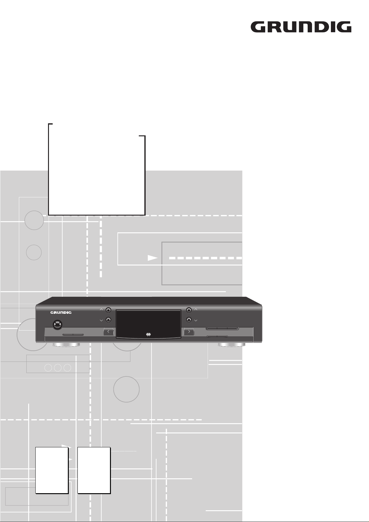
T 22
Service
Manual
T 22
Sach-Nr./Part No.
72010-755.40
TUNING
POWER
MONO/MUTE
BAND PROG. TYPE PROG. TYPE
Zusätzlich erforderliche
Unterlagen für den Komplettservice
Additionally required
Service Manuals for the Complete Service
HIFI HIGH SENSITIVITY RDS PLL SYNTHESIZER TUNER T22
R D S
Service
Manual
Sicherheit
Safety
Sach-Nr./Part No.
72010-800.00
STATION
MEMORY CANCEL ANTENNA/CABLE
INFO EDIT
Btx * 32700 #
Sachnummer
Part Number 72010-755.40
Änderungen vorbehalten
Subject to alteration
Printed in Germany
VK233 1097
Page 2

Allgemeiner Teil / General Section T 22
Es gelten die Vorschriften und Sicherheitshinweise gemäß dem Service Manual "Sicherheit",
Sach-Nummer 72010-800.00, sowie zusätzlich
die eventuell abweichenden, landesspezifischen
Vorschriften!
d
Inhaltsverzeichnis
Seite
Allgemeiner Teil ............................ 1 - 2 … 1 - 7
Meßgeräte / Meßmittel .............................................................. 1 - 2
Technische Daten ..................................................................... 1 - 3
Testmodus ................................................................................ 1 - 3
Ausbauhinweise ........................................................................ 1 - 4
Bedienhinweise ......................................................................... 1 - 6
Abgleich ......................................... 2 - 1 … 2 - 3
Platinenabbildungen
und Schaltpläne .......................... 3 - 1 … 3 - 14
Blockschaltbild .......................................................................... 3 - 1
Display .................................................................................... 3 - 12
Bauteilhinweise ....................................................................... 3 - 10
IC - Block - Diagramme........................................................... 3 - 14
Druckplattenabbildungen
Bedienplatte, Netzteilplatte ............................................... 3 - 11
Tuner ................................................................................ 3 - 13
Schaltpläne
Tuner .................................................................................. 3 - 3
Bedienplatte, Netzteilplatte ................................................. 3 - 7
The regulations and safety instructions shall be
valid as provided by the "Safety" Service Manual,
part number 72010-800.00, as well as the
respective national deviations.
©
Table of Contents
Page
General Section............................. 1 - 2 … 1 - 9
Test Equipment / Aids ............................................................... 1 - 2
Specifications ............................................................................ 1 - 3
Testmode .................................................................................. 1 - 3
Disassembly Instructions .......................................................... 1 - 4
Operating Hints ......................................................................... 1 - 8
Adjustment Procedures................ 2 - 2 … 2 - 3
Layout of the PCBs
and Circuit Diagrams .................. 3 - 1 … 3 - 14
Block Diagram........................................................................... 3 - 1
Display .................................................................................... 3 - 12
Note of Components ............................................................... 3 - 10
IC Block Diagrams .................................................................. 3 - 14
Layout of PCBs
Operating Board, Mains Unit Board.................................. 3 - 11
Tuner ................................................................................ 3 - 13
Circuit Diagrams
Tuner .................................................................................. 3 - 3
Operation Board, Mains Unit Board.................................... 3 - 7
Ersatzteilliste und
Explosionszeichnung ................... 4 - 1 … 4 - 2
Allgemeiner Teil
Meßgeräte / Meßmittel
Oszilloskop
Digitalmultimeter
NF-Voltmeter
Meßsender
Wobbler
Stereocoder
Tongenerator
Klirrfaktormeßgerät
Beachten Sie bitte das GRUNDIG Meßtechnik-Programm, das Sie
unter folgender Adresse erhalten:
GRUNDIG Instruments
Test- und Meßsysteme GmbH
Würzburger Str. 150, D-90766 Fürth/Bay
Tel. 0911/703-4118, Fax 0911/703-4130
Spare Parts List and
Exploded View............................... 4 - 1 … 4 - 2
General Section
Test Equipment / Aids
Oscilloscope
Digital Multimeter
AF Voltmeter
Test Generator
Sweep Generator
Stereo Coder
AF Generator
Distortion Meter
Please note the Grundig Catalog "Test and Measuring Equipment"
obtainable from:
GRUNDIG Instruments
Test- und Meßsysteme GmbH
Würzburger Str. 150, D-90766 Fürth/Bay
Tel. 0911/703-4118, Fax 0911/703-4130
1 - 2 GRUNDIG Service
Page 3
T 22 Allgemeiner Teil / General Section
MUTING
MONO
STEREO AUTO
ANTENNA CABLE
MHz
kHz
BA
LOUD
DIRECTPRO-LOGIC
MUTING
MONO
STEREO AUTO
ANTENNA CABLE
MHz
kHz
BA
LOUD
DIRECTPRO-LOGIC
MUTING
MONO
STEREO AUTO
ANTENNA CABLE
MHz
kHz
BA
LOUD
DIRECTPRO-LOGIC
MUTING
MONO
STEREO AUTO
ANTENNA CABLE
MHz
kHz
BA
LOUD
DIRECTPRO-LOGIC
Technische Daten
Empfindlichkeit
Mono (S/N =26dB) ............................................................ ≤ 1,1µV
Stereo (S/N = 46dB)........................................................... ≤ 35µV
Klirrfaktor
Mono (1kHz, 40kHz Hub)................................................... ≤ 0,2%
Stereo (1kHz, 40kHz Hub) ................................................. ≤ 0,4%
Frequenzbereich (-3dB) ...................................... < 10 … > 15000Hz
Dynamische Trennschärfe
Mono/Stereo, ± 300kHz ..................................................... ≥ 60dB
Geräuschspannungsabstand (IEC Kurve A eff.)
40kHz Hub, DIN A, Mono...................................................... 74dB
40kHz Hub, DIN A, Stereo .................................................... 68dB
Abschwächer im Kabelmodus................................................... 12dB
Empfangsbereich
FM (25kHz Schritte) ......................................... 87,5 … 108,0MHz
MW (1kHz Schritte) ..............................................522 … 1611kHz
Stromversorgung
Netzspannung ..................................................................... 230V~
Netzfrequenz .................................................................... 50/60Hz
Max. Leistungsaufnahme ...................................................... < 8W
Gehäuse
Abmessungen (B x H x T) ................................ 435 x 75 x 300mm
Gewicht .................................................................................3,5kg
Specifications
Input sensitivity
Mono (S/N =26dB) ............................................................ ≤ 1.1µV
Stereo (S/N = 46dB)........................................................... ≤ 35µV
Distortion
Mono (1kHz, 40kHz dev.)................................................... ≤ 0.2%
Stereo (1kHz, 40kHz dev.) ................................................. ≤ 0.4%
Frequency response (-3dB) ............................... < 10 … > 15,000Hz
Dynamic selectivity
Mono/Stereo, ± 300kHz ..................................................... ≥ 60dB
Signal-to-noise ratio (IEC curve A effective value)
40kHz dev., DIN A, Mono...................................................... 74dB
40kHz dev., DIN A, Stereo .................................................... 68dB
Attenuation in cable mode ........................................................ 12dB
Frequency ranges
FM (25kHz steps)............................................. 87.5 … 108.0MHz
MW (1kHz steps)..................................................522 … 1611kHz
Power supply
Mains voltage ...................................................................... 230V~
Mains frequency............................................................... 50/60Hz
Max. power consumption ...................................................... < 8W
Cabinet
Dimensions (W x H x D)................................... 435 x 75 x 300mm
Weight ......................................................................approx. 3.5kg
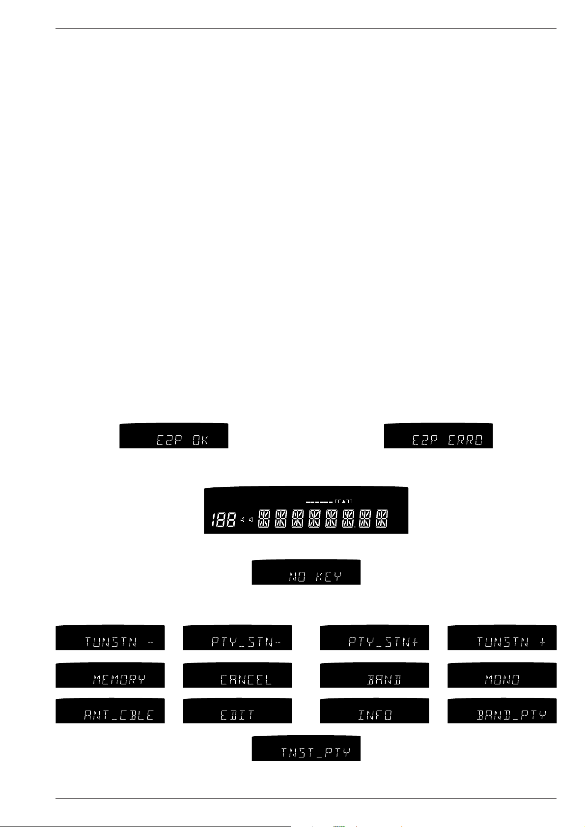
Testmodus
Aktivieren des Testmodus:
- Gerät ausschalten.
- Tasten "PROG. TYPE >" und "MONO/MUTE" gedrückt halten und
Gerät einschalten.
- Jetzt wird das EEPROM getestet. Ist dieses in Ordung erscheint
"E2P OK", ansonsten "E2P ERROR" und der Test wird gestopt.
MONO
MUTING
STEREO AUTO
DIRECTPRO-LOGIC
LOUD
BA
- Es werden jetzt nacheinander alle Segmente des Displays eingeschaltet.
- Nach einigen Sekunden wechselt die Anzeige dann auf:
- Beim Drücken der einzelnen Tasten wird die jeweilige Taste im
Display angezeigt:
ANTENNA CABLE
MUTING
kHz
MHz
MONO
STEREO AUTO
DIRECTPRO-LOGIC
LOUD
BA
MONO
MUTING
STEREO AUTO
DIRECTPRO-LOGIC
LOUD
BA
Testmode
Activating the Testmode:
- Switch off the unit.
- Hold the buttons "PROG. TYPE >" and "MONO/MUTE" depressed
and switch on the unit.
- Now the EEPROM is being checked. If it is all right, then "E2P OK"
is display, otherwise "E2P ERROR" and the test stops.
- Now all segments in the display will be illuminated one after another.
ANTENNA CABLE
kHz
MHz
- After a few seconds the display changes to:
ANTENNA CABLE
kHz
MHz
- When pressing one of the buttons, the respective button is shown in
the display:
MONO
MUTING
STEREO AUTO
DIRECTPRO-LOGIC
LOUD
BA
MONO
MUTING
STEREO AUTO
DIRECTPRO-LOGIC
LOUD
BA
MONO
MUTING
STEREO AUTO
DIRECTPRO-LOGIC
LOUD
BA
- Beenden des Testmodus durch Ausschalten des Gerätes.
GRUNDIG Service 1 - 3
ANTENNA CABLE
ANTENNA CABLE
ANTENNA CABLE
MONO
MUTING
STEREO AUTO
DIRECTPRO-LOGIC
MUTING
MUTING
MONO
MONO
LOUD
DIRECTPRO-LOGIC
LOUD
DIRECTPRO-LOGIC
LOUD
BA
STEREO AUTO
BA
STEREO AUTO
BA
kHz
MHz
kHz
MHz
kHz
MHz
ANTENNA CABLE
ANTENNA CABLE
ANTENNA CABLE
MUTING
MONO
DIRECTPRO-LOGIC
LOUD
kHz
MHz
kHz
MHz
kHz
MHz
BA
STEREO AUTO
ANTENNA CABLE
MONO
MUTING
STEREO AUTO
DIRECTPRO-LOGIC
LOUD
BA
MONO
MUTING
STEREO AUTO
DIRECTPRO-LOGIC
LOUD
BA
MONO
MUTING
STEREO AUTO
DIRECTPRO-LOGIC
LOUD
BA
kHz
MHz
- To end the testmode switch off the unit.
ANTENNA CABLE
ANTENNA CABLE
ANTENNA CABLE
kHz
MHz
kHz
MHz
kHz
MHz
Page 4
Allgemeiner Teil / General Section T 22
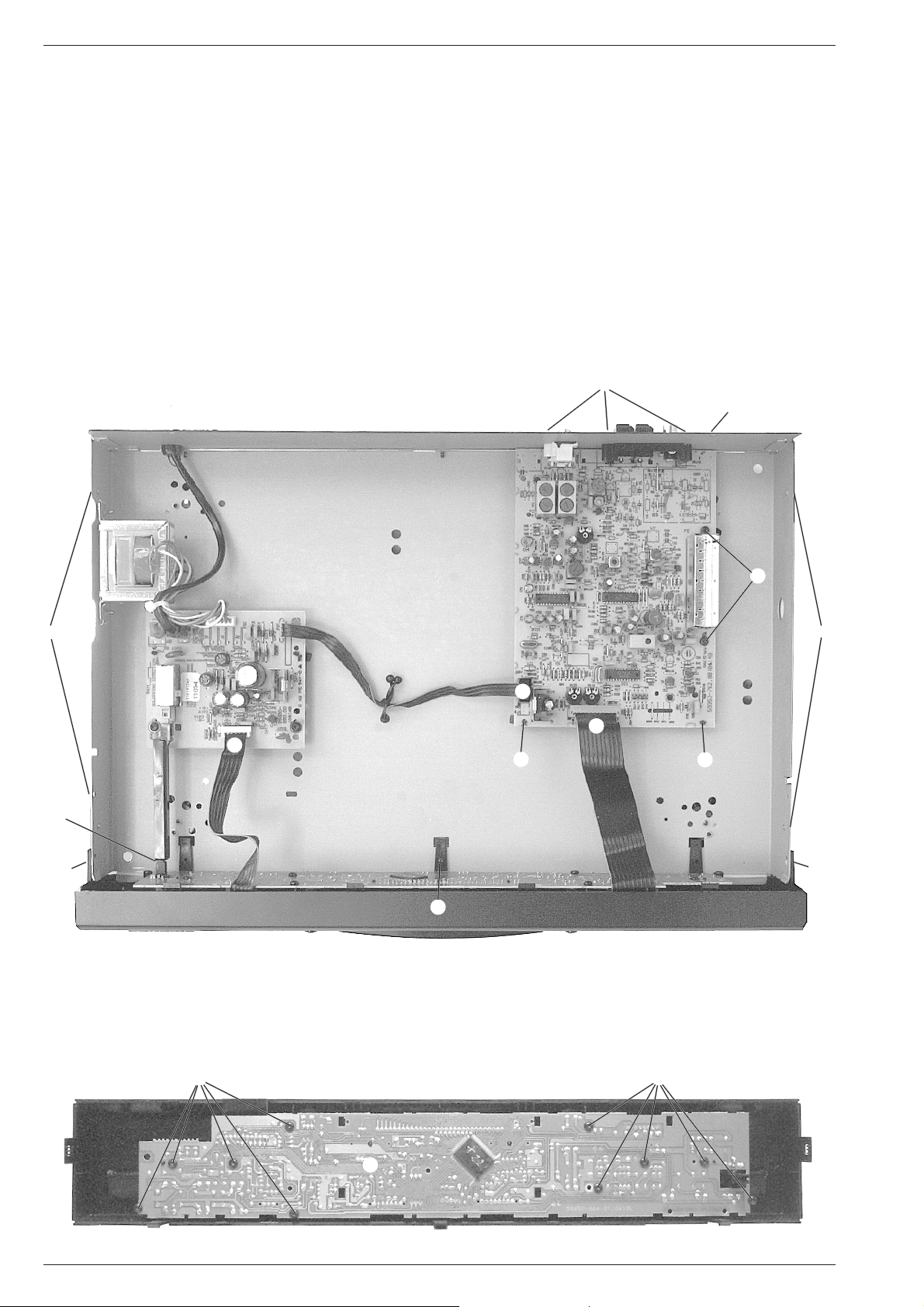
Ausbauhinweise
1. Öffnen des Gehäuses (Fig. 1)
- Die 4 Schrauben A und die 2 Schrauben B herausschrauben.
- Den Deckel abheben.
2. Ausbau der Frontplatte (Fig. 1)
- Schraube E herausschrauben.
- Die Rastung C der Netztaste ausrasten.
- Die 2 Stecker D und F abziehen.
- Die 2 Rastnasen G ausrasten.
3. Ausbau der HF-Platte (Fig. 1)
- Die 2 Stecker F und H abziehen.
- Die 3 Schrauben P und die beiden Schrauben Q herausschrauben.
- Die Abstandsrollen der mit } gekennzeichneten Schrauben Q sind
aus Metall. Diese dienen zur Erdung der Leiterplatte und müssen an
diesen Stellen verbleiben.
- Die 2 Halter J ausrasten.
Fig. 1
B
Disassembly Instructions
1. Opening the Cabinet (Fig. 1)
- Undo the 4 screws A and the 2 screws B.
- Remove the top of the cabinet.
2. Removing Front Panel (Fig. 1)
- Undo screw E.
- Disengage the mains button C.
- Disconnect the 2 plug-in-connections D and F.
- Disengage the 2 catches G.
3. Removing the RF-Board (Fig. 1)
- Disconnect the 2 plug-in-connections F and H.
- Undo the 3 screws P and the 2 screws Q.
- The spacing pieces of the screws Q marked } are metalic. They are
for earthing of the PCB and they must stay at this place.
- Disengage 2 holder J.
P
B
A
C
G
D
E
H
J
}
Q
}
A
F
J
G
4. Zerlegen der Frontplatte (Fig. 2)
- 10 Schrauben K herausschrauben.
- Die Leiterplatte L kann jetzt abgenommen werden.
Fig. 2
K
4. Disassembling of the Front Panel (Fig. 2)
- Undo 10 screws K.
- The PCB L can now be removed.
K
L
1 - 4 GRUNDIG Service
Page 5
T 22 Allgemeiner Teil / General Section
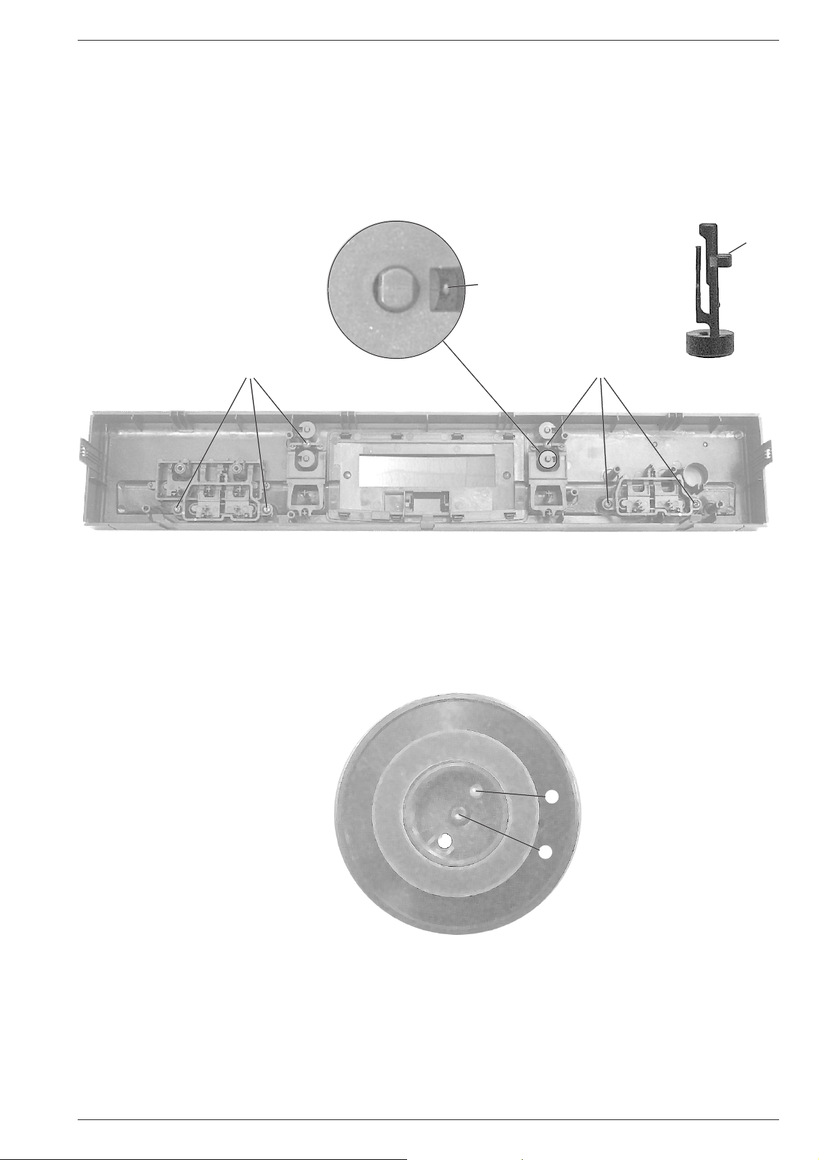
5. Ausbau der Tasten "Tuning" / "Station" (Fig. 3)
- Mit einem kleinen Schraubendreher die Rastnase M vorsichtig
ausrasten. Die Taste kann jetzt nach außen entnommen werden.
- Beim Einbau muß die Rastnase M an der Nase R (Fig.4) einrasten.
6. Ausbau der Tasten (Fig. 3)
- Die entsprechenden Schrauben N herausschrauben.
- Die Tasten aus den Führungen ziehen.
Fig. 3
N
5. Disassembling the "Tuning" / "Station" buttons (Fig. 3)
- Disengage the catch M with a small screw driver carefully. The
button can now be removed towards the outside.
- When reassembling catch M must look at nose R (Fig.4).
6. Disassembling the buttons (Fig. 3)
- Undo the corresponding screws N.
- Pull the buttons out of the Front.
Fig. 4
R
M
N
7. Ausbau eines Fußes (Fig. 5)
- Die Schraube O herausschrauben.
- Beim Einsetzen des Fußes auf Rastnase P achten.
Fig. 5
7. Removing a foot (Fig. 5)
- Undo screw O.
- Take care of the catch P when fitting the foot.
P
O
GRUNDIG Service 1 - 5
Page 6
Allgemeiner Teil / General Section T 22
1 - 6 GRUNDIG Service
Bedienhinweise Dieses Kapitel enthält Auszüge aus der Bedienungsanleitung. Weitergehende Informationen entnehmen Sie bitte der gerätespezifischen Bedienungsanleitung, deren Sachnummer Sie in der
entsprechenden Ersatzteilliste finden.
Einleitung
Ihr Gerät T 22 ist ein HiFi-RDS-Tuner, der der
traditionellen Qualität der Radiotechnologie von
Grundig nachgeht.
• Eine ausgesprochen gute Empfangsqualität
wird durch sehr gute Auswahl, Empfindlichkeit
und Dynamik erzielt.
• Sogar ungewünschte Störungen bei hoher
Empfangsstärke können durch den
Antennenabschwächer vermieden werden (FM
ANTENNA, FM CABLE). Diese Funktion
erlaubt sowohl den Empfang über eine lokale
Antennendose als auch die Hausantenne
außerdem, für die Experten unter Ihnen, unterdrückt der 19 MHz MPX-Filter Überlappungen
der Pilottöne und Hörfrequenzen.
• Störungen von Nachbarsendern oder
Geräusche aufgrund von schwachem Empfang
können reduziert oder sogar abgestellt
werden, indem Sie die Mono-Funktion
einsetzen.
• 59 Senderspeicher und eine komplette,
effektive RDS-Decodierung versichern einfache
Handhabung und Komfort durch Anzeige der
Sendernamen, laufendem Radiotext,
Programmartauswahl und Zeitangabe.
• Der Tuner kann über die Fernbedienung des
Verstärkers fernbedient werden.
EINLEITUNG
Hauptfunktionen Ihres Tuners
Funktionen, die über das Gerät gesteuert
werden:
• Auswahl des Wellenbereichs: FM ANTENNA,
FM CABLE und MW.
• Empfangsmodus: STEREO, MONO.
• Automatische und manuelle
Senderabstimmung.
• 59 Senderspeicher.
• Automatische Speicherung der Sender.
• Sukzessives Aufrufen der gespeicherten
Sender.
• Durchlaufen der Displayanzeigen: (RDS)
Sendername, Radiotext, Zeitangabe,
Frequenz.
• Namensvergabe für Sender ohne RDS.
• Auswahl eines Senders gemäß der jeweiligen
Programmart.
• Sprachauswahl für die Programmart.
Funktionen über Systemfernbedienung
(geliefert mit dem Verstärker V21 oder V23):
• Direkte Auswahl der gespeicherten
Senderspeicher mit den Ziffern 1...0.
• Aufruf der gespeicherten Speicherplätze mit
den Tasten $ STATION TUNER #.
• Durchlaufen der Displayanzeigen: (RDS)
Sendername, Radiotext, Zeitangabe,
Frequenz.
• Namensvergabe für Sender ohne RDS.
• Auswahl eines Senders gemäß der jeweiligen
Programmart.
RDS RADIO DATA SYSTEM
R
Ihr Gerät ist ein RDS-Gerät.
RDS (Radio Data System) steht für eine neue Ära
des Rundfunk-empfanges, die dem Hörer/Benutzer zunächst mehr Komfort und besseren
Empfang beschert, und bietet extra nutzvolle
Information.
Haben Sie einen RDS-Sender eingestellt, wird
nach kurzer Zeit der Sendername angezeigt.
Mit der INFO-Taste können Sie auch andere RDSInformationen, wie RDS-Zeit und Radiotext
aufrufen (siehe Seite 10).
RDS Radio Data System
Ihr Gerät ist in der Lage, RDS-Informationen, die
mit dem Sendersignal ausgestrahlt werden, zu
empfangen und auszuwerten. Der Sendername
wird im Display angezeigt und automatisch in
den Programmspeicher übernommen. Schon
vorhandene Namen werden überschrieben.
RDS TIME
Einige RDS-Sender strahlen die Information 'RDSZEIT' aus. Die Zeitanzeige wird jede Minute
aktualisiert. Die Genauigkeit der Zeit hängt von
der übertragenen Information ab.
RADIOTEXT
Immer mehr RDS-Sender strahlen die Information
RADIOTEXT aus. Dies sind Zusatzinformationen
zu Sender und Programm.
RADIOTEXT erscheint als Laufschrift im Display.
Da RADIOTEXT vom Sender Zeichen für Zeichen
übertragen wird, kann es einige Zeit dauern, bis
der Text vollständig empfangen worden ist.
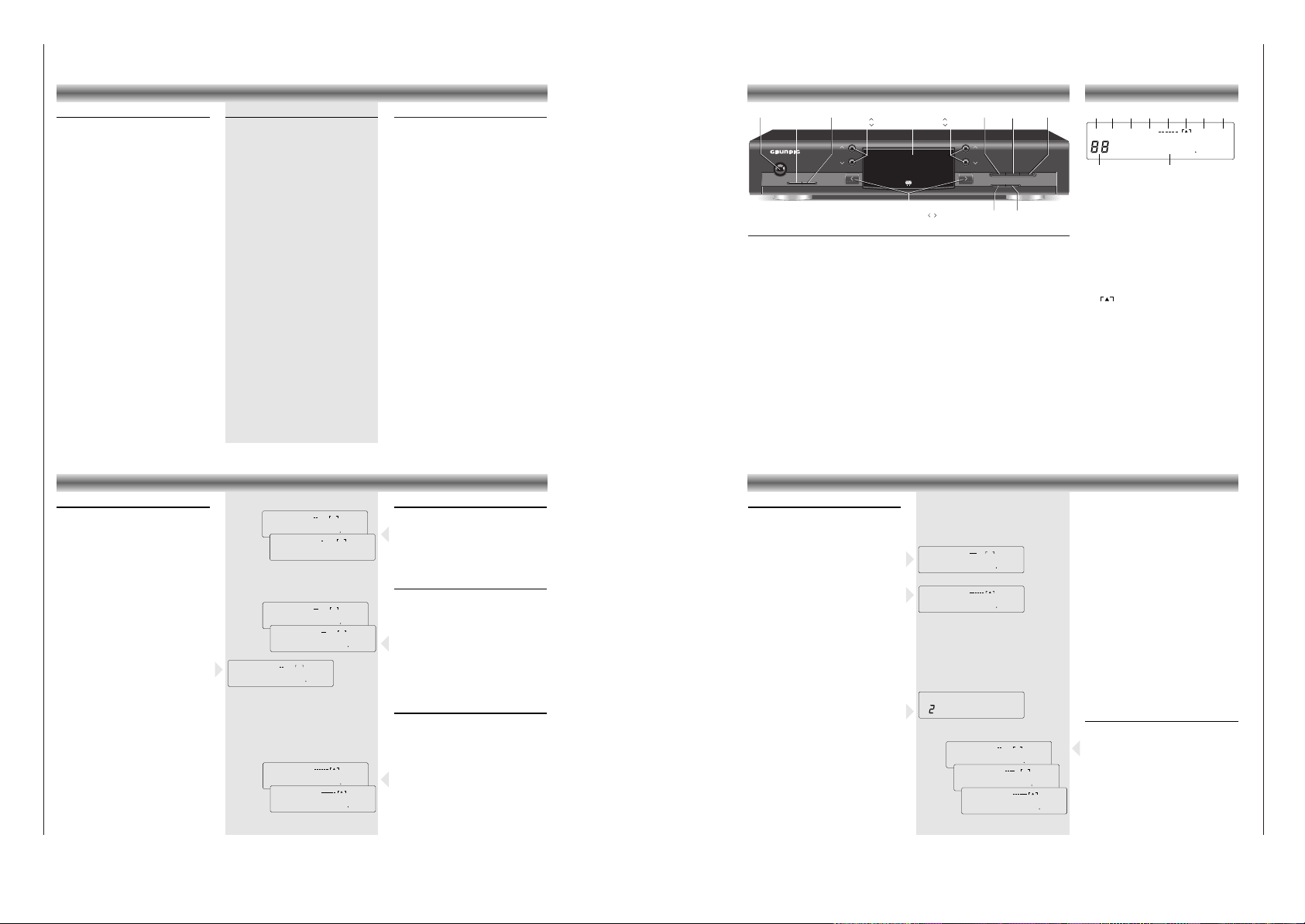
Vorderseite des Tuners
POWER Dieser Schalter wird zum Ein- und Ausschalten des Geräts verwendet.
MONO/MUTE
Mit dieser Taste schalten Sie auf MONO-Empfang um, wenn z. B. der Stereo-Empfang
durch Rauschen gestört ist. Gleichzeitig wird die Funktion MUTING abgeschaltet.
BAND Mit dieser Taste schalten Sie zyklisch zwischen den Bändern
FM und MW.
TUNING #$
Mit diesen Tasten starten Sie den Sendersuchlauf (AUTO TUNING) oder schalten die
Frequenz in die gewünschte Richtung Schritt für Schritt (MANUAL TUNING) weiter.
Halten Sie die Taste länger gedrückt, erfolgt die Weiterschaltung im Schnellgang.
STATION
#$
Mit diesen Tasten schalten Sie die Speicherplätze in aufsteigender (#) oder
abfallender ($) Richtung durch.
MEMORY Diese Taste speichert einen eingestellten Sender auf den jeweils niedrigsten,
freien
Speicherplatz. Längeres drücken dieser Taste startet die Funktion AUTO STORE.
CANCEL Mit dieser Taste löschen Sie einzelne Speicherplätze oder den gesamten
Speicherinhalt (länger als 10 Sekunden gedrückt halten).
ANTENNA/CABLE
Mit dieser Taste schalten Sie einen Antennen-abschwächer ein, um Störungen durch
ein zu starkes Eingangssignal zu vermeiden, wenn Sie Ihren Tuner an das
Breitbandkabel angeschlossen haben.
PROG. TYPE ! @ Mit diesen Tasten wählen Sie eine der Programm-arten an.
INFO Mit dieser Taste schalten Sie die Anzeige zwischen Sendernamen (RDS), einem
eigenen Namen, RADIOTEXT, RDS Zeit und Sender-Frequenz um.
EDIT
Mit dieser Taste wählen Sie den Eingabemodus an, um einen Sendernamen zu vergeben.
BEDIENELEMENTE DISPLAY
1 MUTING – Leuchtet auf, wenn die Funktion
MUTING aktiviert ist.
2 MONO – Leuchtet auf, wenn die Funktion
MONO aktiviert wurde.
3 STEREO – Leuchtet auf, wenn im Wellen-
bereich FM Stereo-Sendungen empfangen
werden.
4 AUTO – Diese Anzeige leuchtet auf, wenn
die Funktion AUTO TUNING aktiv ist.
5 Signalstärke-Anzeige – Je mehr Striche im
Display erscheinen, desto stärker empfangen
Sie den eingestellten Sender.
6 – Bei exakter Abstimmung auf die
Sendermitte leuchtet das Dreieck
auf.
7
ANTENNA – leuchtet auf, wenn der Antennenabschwächer ausgeschaltet ist. (FM ANTENNA).
8 CABLE – leuchtet auf, wenn bei Breitband-
kabelempfang der Antennenabschwächer
eingeschaltet ist. (FM CABLE).
9 Station number Siebensegment-Anzeige –
Hier wird die Nummer des gewählten
Speicherplatzes (1bis 59) angezeigt.
0 14 Segment-Anzeige – für (RDS)
Sendername, Frequenzen, Radiotext, RDS
Zeit, Programmart oder Informationen.
MUTING
MONO
STEREO AUTO
ANTENNA CABLE
########
MHz
12 3 4 5 6 708
kHz
9
HIFI HIGH SENSITIVITY RDS PLL SYNTHESIZER TUNER T22
MONO/MUTE
TUNING
POWER
STATION
BAND PROG. TYPE PROG. TYPE
MEMORY CANCEL ANTENNA/CABLE
INFO EDIT
R D S
TUNINGBANDMONO/MUTEPOWER DISPLAY STATION
EDITINFOPROG. TYPE
MEMORY
ANTENNA/CABLE
CANCEL
Ein- und Ausschalten
• Schalten Sie Ihr Gerät ein, indem Sie den
Netzschalter POWER betätigen. Die
Betriebsanzeige, eine gelbe LED in der Mitte
des Einschaltknopfes, informiert Sie über den
Schaltzustand: gedrückt: EIN
ausgerastet: AUS.
• Wollen Sie das Gerät ausschalten, drücken
Sie den Netz-Schalter POWER nochmals
(ausrasten).
• Haben Sie den TUNER an die Wechselspannungs-Ausgänge AC OUTLETS des
Verstärkers angeschlossen, dient der
Netzschalter des Verstärkers als Zentralschalter. Lassen Sie den Schalter POWER des
Tuners immer gedrückt.
– Schalten Sie Ihr Gerät nach dem Auspacken
zum ersten Mal ein, wählt das Gerät 'FM
ANTENNA', das Display zeigt 87,50 MHz
und MUTING. Die Empfangsart STEREO ist
gewählt.
– Jedes Mal, wenn Sie das Gerät wieder
einstellen, wählt es automatisch den Sender,
den Sie vor dem Ausschalten eingestellt hatten.
BEDIENUNG
Wellenbereichswahl
• Wählen Sie den gewünschten Wellenbereich
(FM oder MW), indem Sie die Fortschalt-Taste
BAND drücken.
• Jedes Betätigen der Taste schaltet zum
nächsten Wellenbereich weiter.
– Das Display informiert Sie über den
eingestellten Bereich.
Antennenanpassung
Empfangen Sie Ihre Sender über das Breitbandkabel einer öffentlichen oder privaten BetreiberGesellschaft, kann es vorkommen, daß an Ihrer
Antennen-Dose ein sehr hoher Pegel anliegt, der
zu Störungen führen kann.
• Drücken Sie deshalb die Taste ANTENNA/-
CABLE, um den Eingangs-abschwächer einzuschalten. Im display erscheint ‘CABLE’. Dadurch
wird die Empfindlichkeit des Antenneneinganges
herabgesetzt und Störungen durch das Kabel
vermieden. Diese Einstellung wird nach 5
Sekunden automatisch abgespeichert.
FM-Empfangsart STEREO/MONO
Im Normalfall ist Ihr Gerät in Stereo-Bereitschaft.
Sobald ein empfangswürdiges Stereo-Signal
registriert wird, leuchtet im Display 'STEREO' auf.
Ist der Stereo-Empfang gestört, erlischt das
Zeichen. Störgeräusche, etc. werden unterdrückt.
• Ist der Stereo-Fernempfang gestört, können Sie
Ihr Gerät auf MONO-Empfang schalten.
• In diesen Fällen drücken Sie die Taste MONO.
– Das Zeichen MUTING erlischt im Display, das
Zeichen MONO leuchtet.
Die MUTING-Funktion ist bei MONO immer
ausgeschaltet, so daß Sie auch sehr schwache
Sender einstellen können.
➥
MUTING
STEREO
ANTENNA
FM 9350
MHz
MONO ANTENNA
FM 9350
MHz
➥
MUTING
ANTENNA
FM 8750
MHz
MUTING
ANTENNA
FM 8750
MHz
MUTING
CABLE
FM 8750
MHz
➥
➥
MUTING
ANTENNA
FM 8750
MHz
MW 528
kHz
➥
➥
Automatischer Sendersuche
• Um die Funktion ‘SUCHLAUF’ (AUTO
TUNING) aufzurufen, betätigen Sie die Tasten
TUNING#oder $, bis die Frequenzanzeige
‘zu laufen’ beginnt. Lassen Sie dann die Taste
los.
– Im Display erscheint das Zeichen "AUTO". Das
Zeichen erlischt nach Beendigung der Funktion
"SUCHLAUF".
– Der Suchlauf stoppt, sobald er einen Sender
mit ausreichender Empfangsstärke gefunden
hat. Im Display leuchtet ein Dreieck auf.
– Jedesmal, wenn Sie den Suchlauf starten,
schaltet das Gerät auf STEREO.
– Eine Anzeige informiert Sie zudem über die
Feldstärke. Je mehr Striche im Display
erscheinen, desto stärker wird der Sender
empfangen.
– Die Frequenz des empfangenen Senders wird
in MHz (FM) oder kHz (MW) angezeigt.
– Stoppt der Suchlauf, überprüft die Funktion
'AUTO COMPARE', ob diese Frequenz schon
im Senderspeicher abgelegt ist. Ist dies der
Fall, wird der Speicherplatz links und, falls
vorhanden, der Name des Senders,
angezeigt.
– Stationen, die mit geringer Feldstärke
empfangen werden, können vom Suchlauf
übersprungen werden. Diese können mittels
Handabstimmung eingestellt werden.
• Bei Bedarf können Sie den Suchlauf auch
unterbrechen, indem Sie die Tasten TUNING
#
oder $erneut drücken.
SENDERSUCHE
➥
➥
MUTING
ANTENNA
FM 9305
MHz
MUTING
ANTENNA
FM 9307
MHz
MUTING
STEREO
ANTENNA
FM 9310
MHz
RADIO 2
MUTING
STEREO
ANTENNA
FM 9790
MHz
MUTING
AUTO
ANTENNA
FM 9985
MHz
Manuelle Sendersuche
(Handabstimmung)
•
Tippen Sie die Tasten TUNING#oder $kurz
an, um in die entsprechende Richtung in
Einzelschritten (FM: 25kHz; MW: 1 kHz)
abzustimmen.
– Hier werden Sie ebenfalls durch das Auf-
leuchten des Leuchtdreiecks und durch die
Anzahl der Striche über die Qualität des
einfallenden Senders informiert.
– Auch hier überprüft die Funktion 'AUTO
COMPARE', ob diese Frequenz schon im
Senderspeicher abgelegt ist.
Page 7

T 22 Allgemeiner Teil / General Section
GRUNDIG Service 1 - 7
STATIONSSPEICHER
Festsenderspeicher
Sie haben 59 Speicherplätze zur Verfügung.
• Stimmen Sie den Sender, den Sie speichern
wollen, per Suchlauf oder manuell ab.
• Drücken Sie die Taste MEMORY.
– Der gefundene Sender wird auf den nächsten
freien Speicherplatz gelegt. Sie müssen also
keine Speicherplatznummer eingeben.
– Die erste gespeicherte Station erhält die
Speicherplatznummer 1, die nächste Station
die Nummer 2 und so fort.
– Die Software des Tuners überprüft jetzt den
Stationsspeicher nach freien Speicherplätzen.
Sind alle Plätze belegt, zeigt das Display für
ca. 1,5 Sekunden MEM FULL.
• Möchten Sie eine bereits gespeicherte Station
"verschieben", d.h. auf einen anderen
Speicherplatz legen, drücken Sie MEMORY.
– Die Station wird immer auf den ersten freien
Speicherplatz gelegt.
•
Drücken Sie MEMORY mehrmals, werden die freie
Speicherplätze der Reihe nach durchgetastet.
Beispiel: Ihr Lieblingssender soll von Speicherplatznummer '6' auf Speicherplatznummer '1'
abgelegt werden.
• Wählen Sie Speicherplatznummer '1'.
• Drücken Sie die Taste CANCEL einmal.
– Speicherplatz '1' ist jetzt gelöscht.
Sie können auch die Taste MEMORY drücken,
um den auf Position “1” gespeicherten Sender
auf die nächst freie Position zu verschieben.
• Wählen Sie jetzt Platz '6' an, Ihren Lieblingssender, danach die Taste MEMORY.
Jetzt ist Ihr Sender auf Speicherplatz '1' abgelegt.
– Es ist nicht möglich, eine Frequenz auf zwei
Speicherplätzen abzulegen.
– Die Einstellungen MONO/STEREO und
ANTENNA/CABLE werden bei jedem
Wechsel automatisch gespeichert.
MUTING
ANTENNA
AS 8810
MHz
➥
MUTING
STEREO
ANTENNA
FM 9790
MHz
MUTING
STEREO
ANTENNA
FM 9790
MHz
MEM FULL
MUTING
STEREO
ANTENNA
FM 9790
MHz
Funktion AUTOSTORE
Dieser Tuner ist mit einer Funktion ausgestattet,
über die man auf sehr komfortabele Weise alle
FM (UKW) Radiosender automatisch speichern
kann.
• Drücken Sie MEMORY und halten Sie die
Taste gedrückt, bis AS im Display erscheint.
– Die AUTO STORE-Funktion ist nun gestartet.
– Der Tuner beginnt von der aktuellen Frequenz
aus die Sender zu lokalisieren und speichert
zunächst alle RDS-Sender, die sich noch nicht
im Speicher befinden, ab.
– Danach sucht er alle starken UKW Sender
ohne RDS und zum Schluß die schwachen.
– Diese Funktion versichert Ihnen, daß alle UKW
Sender, die über eine ausreichende Empfangsstärke verfügen, in Ihren Stationsspeicher
aufgenommen werden.
• Sie können die AUTO STORE-Funktion
unterbrechen, indem Sie MEMORY erneut
drücken.
Aufrufen eines Senderspeichers
• Möchten Sie einen Senderspeicher (Speicherplatz) aufrufen, betätigen Sie die Tasten
STATION#oder $. Die gespeicherten
Stationen werden in aufsteigender (#) oder
fallender ($) Reihenfolge aufgerufen.
Die Speicherplätze können auch über die SystemFernbedienung angewählt werden (siehe Seite 12).
Speicherplatz löschen
• Wollen Sie einen belegten Speicherplatz
wieder löschen, frei-machen, rufen Sie zuerst
seine Nummer auf.
• Drücken Sie STATION
#
oder $solange
, bis
Sie den Speicherplatz, den Sie freimachen wollen,
ausgewählt haben,
oder wählen Sie den
Speicherplatz über die Tastatur der Fernbedienung - entweder direkt über die Zifferntasten
oder mit den Tasten $ STATION TUNER #.
(vorausgesetzt, daß zuerst die Taste
TUNER auf
der Fernbedienung gedrückt wurde
)
• Drücken Sie die Taste CANCEL.
– Ist der Speicherplatz gelöscht, erlischt die
Speicherplatznummer im Display.
• Möchten Sie alle Speicherplätze löschen, z.B.
nach einem Umzug, halten Sie CANCEL für 5
Sekunden gedrückt.
– Im Display erscheint für kurze Zeit 'ERASE
?'.
• Halten Sie die Taste noch für 5 weitere
Sekunden gedrückt, bis das Display die
Frequenz '87,5 MHz' zeigt
– Alle Senderspeicher sind gelöscht.
• Drücken Sie jetzt eine der Tasten STATION
#
oder $, so erscheint im Display 'FREE'.
• Wenn Sie die Taste CANCEL loslassen, bevor
diese fünf Sekunden verstrichen sind, wird die
Löschfunktion nicht ausgeführt.
STATIONSSPEICHER WEITERE FUNKTIONEN
_
RDS-DATA
MUTING
STEREO
ANTENNA
FM 8750
MHz
ERASE
MUTING
STEREO
ANTENNA
FM 9790
MHz
AB_
➥
➥
➥
BAYERN 3
➥
13 45
ARD-RADI
MUTING
STEREO
ANTENNA
FM 9790
MHz
Umschalten der Anzeige
• Drücken Sie die Taste INFO, wechselt die
Anzeige zwischen Stationsnamen (RDS oder
eigen vergeben), RDS-Zeit, RADIOTEXT (bei
RDS-Sendern) und Frequenz.
– Bei Anzeige des Stationsnamens wird links
daneben nur die Speicherplatznummer
angezeigt.
Sendernamen vergeben
Empfangen Sie Sender, die den RDS-Code nicht
ausstrahlen, können Sie jeder Station einen
Namen Ihrer Wahl geben.
• Drücken Sie die Taste EDIT.
• Mit den Tasten
TUNING#oder $können Sie
die Eingabemarke, den Cursor, in die
jeweilige Richtung bewegen. Ihnen stehen
insgesamt 8 Eingabestellen zur Verfügung.
• Mit den Tasten STATION#oder $laufen Sie
vorwärts (#) oder rückwärts ($) durch das
Alphabet, das Leerzeichen und die Zahlen von
0 - 9.
• Wollen Sie die Eingabe beenden, den
Eingabemodus verlassen und abspeichern,
drücken Sie erneut die Taste EDIT.
Anmerkung:
Versuchen Sie, einem Sender, der RDS-Codes
ausstrahlt, einen Namen Ihrer Wahl zu geben,
informiert Sie das Display mit der Anzeige RDS-
DATA über die Eingabesperre.
Löschen eines Namens
• Drücken Sie im Eingabemodus die Taste
CANCEL, wird der bisherige Name gelöscht
und die Einfügemarke springt an die erste
Position.
Programmart (PTY)
RDS bietet Ihnen die Möglichkeit, gespeichterte
FM-Sender nach Programmarten auszuwählen.
Mehr und mehr Sender codieren ihre Programmart und erlauben damit eine erfolgreiche Suche
mit der Funktion PTY. Der übertragene Code steht
jedoch unter Verantwortung des Radiosenders.
Es sind 29 Programmarten definiert.
• Mit den Tasten PROG. TYPE ! @ (oder PTY auf
der Fernbedienung) können Sie die
Programmarten der Reihe nach aufrufen.
– Das Display zeigt die aktuelle Programmart.
– Nach 2 Sekunden beginnt das Gerät die
gespeicherten Sender zu scannen, um die
gewünschte Programmartübertragung zu
finden. Sobald dies der Fall ist, wird der
Sender eingestellt.
– Wird die aktuelle Kennung von keiner Station
übertragen, zeigt das Display für kurze Zeit:
'NONE' ('KEINE').
– Wenn Sie eine Programmart aufrufen und
(noch) keine FM-Sender gespeichert sind,
erscheint für kurze Zeit 'FREE' im Display.
Sprachwahl
Sie können die Anzeige der Programmart in den
Sprachen Englisch, Französisch und Deutsch
aufrufen.
• Halten Sie im ausgeschalteten Zustand die
Taste EDIT gedrückt und schalten Sie den Tuner
ein.
– Im Display erscheint die aktuelle Sprache.
• Mit den Tasten STATION
#$
können Sie die
gewünschte Sprache aufrufen.
• Speichern Sie Ihre Wahl mit Taste MEMORY.
PROGRAMMART
➥
➥
ENGLISH
FRANCAIS
DEUTSCH
➥
NONE
➥
➥
NEWS
AFFAIRS
INFO
Es sind 29 Programmarten definiert:
NEWS = Nachrichtendienste
AFFAIRS = Politik und Zeitgeschehen
INFO = Spezielle Wortprogramme
SPORT = Sportsendungen aller Art
EDUCATE = Lernen und Weiterbildung
DRAMA = Hörspiel und Literatur
CULTURE = Kultur und Gesellschaft
SCIENCE = Wissenschaft
VARIED = Unterhaltungsmusik
POP M = Popmusik
ROCK M = Rockmusik
M.o.R. M = ‘easy-listening’, Reisemusik.
LIGHT M = Leichte klassische Musik
CLASSICS = Ernste klassische Musik
OTHER M = Andere Musikarten
WEATHER = Wetterberichterstattung
FINANCE = Finanzielle Berichte und Handel
CHILDREN = Kinderprogramme
SOCIAL A = Sozialgeschehen
RELIGION = Kirchenfunk, Andachten und
Gottesdienste
PHONE IN = Programme, in denen Hörer ihre
Ansichten per Telefon mitteilen
können
TRAVEL = Reiseberichte
LEISURE = Programme zu Freizeitaktivitäten
JAZZ = Jazzmusik
COUNTRY = Countrymusik
NATIONAL = Nationale Musik
OLDIES = Musik der sogenannten ‘golden
age’ der populären Musik
FOLK M = Volksmusik
DOCUMENT = Dokumentationen
Auswahl des Tuners:
• Drücken Sie die Taste TUNER.
Damit die folgende Funktionen auch ausgeführt
werden können, stellen Sie bitte sicher, daß zuerst
die Taste TUNER auf der Fernbedienung gedrückt ist.
Abstimmen:
• Drücken Sie die Taste Q oder R um in die
entsprechende Richtung abzustimmen.
Aufrufen eines Senderspeichers
• Drücken Sie die Tasten $ STATION TUNER #, um
die gespeicherten Speicherplätze nacheinander
aufzurufen. Leere Plätze werden übersprungen.
• Geben Sie die Speicherplatznummer mit den
Zifferntasten 1...0 direkt ein:
• Bei einstelligen Speicherplatznummern betätigen
Sie die entsprechende Zifferntaste nur kurz.
• Um zweistellige Nummern zu speichern, drücken
Sie die erste Ziffer eine längere Zeit, bis diese
auf die linke Seite des Displays springt z.B.: 4--.
• Geben Sie danach die Einerstelle ein.
– Haben Sie einen Speicherplatz angewählt, der
(noch) nicht belegt ist, erscheint für kurze Zeit
'FREE' im Display. Danach schaltet das Gerät
auf den zuletzt eingestellten Speicherplatz zurück.
Umschalten der Anzeige
• Drücken Sie die Taste TXT/6, wechselt die Anzeige
zwischen Stationsnamen (RDS oder eigen vergeben),
RDS-Zeit, RADIOTEXT (bei RDS-Sendern) und Frequenz.
– Bei Anzeige des Stationsnamens wird links daneben
nur die Speicherplatznummer angezeigt.
SYSTEMFERNBEDIENUNG
Sendernamen vergeben
Empfangen Sie Sender, die den RDS-Code nicht ausstrahlen, können Sie jeder Station einen Namen Ihrer
Wahl geben.
• Drücken Sie auf der Fernbedienung die Taste TXT/6
länger als 1 Sekunde.
• Mit den Tasten Q oder R können Sie die
Eingabemarke, den Cursor, in die jeweilige
Richtung bewegen. Ihnen stehen insgesamt 8
Eingabestellen zur Verfügung.
• Mit den Tasten $ STATION TUNER # laufen Sie
vorwärts (UP) oder rückwärts (DOWN) durch das
Alphabet, das Leerzeichen und die Zahlen von 0 - 9.
• Wollen Sie die Eingabe beenden, den Eingabemodus verlassen und abspeichern, drücken Sie
erneut die Taste TXT/6.
Programmart (PTY)
• Drücken Sie die Taste PTY.
– Das Display zeigt die aktuelle Programmart.
• Durch Drücken der Tasten
$ STATION
TUNER
#
innerhalb von 2 Sekunden starten Sie den Aufruf der
Programmarten nacheinander.
– Nach 2 Sekunden beginnt das Gerät die
gespeicherten Sender zu scannen, um die
gewünschte Programmartübertragung zu finden.
Sobald dies der Fall ist, wird der Sender eingestellt.
– Wird die aktuelle Kennung von keiner Station
übertragen, zeigt das Display für kurze Zeit:
'NONE' ('KEINE').
– Wenn Sie eine Programmart aufrufen und (noch)
keine FM-Sender gespeichert sind, erscheint für
kurze Zeit 'FREE' im Display.
1 2 3 4 5
6 7 8 9 0
STATION TUNER
VOLUME
SAT
TV
TAPE
CD
TUNER VCR
SAT
TV
8
3
AUDIO/VIDEO RC - -URC20
by
1
E
a
P
P
P
HIFI
88
TXT/6
P
P
P
AV
TV VOLUME
–
+
CENTRE/+
SURROUND/INST.
REAR/–
$
#
2
w
DISC/PTY
Diese Fernbedienung ist Teil des Lieferumfanges
des Verstärkers V23 oder V21.
Folgende Radiofunktionen können über die Fernbedienung ausgeführt werden:
Page 8

Allgemeiner Teil / General Section T 22
1 - 8 GRUNDIG Service
Operating Hints This chapter contains excerpts from the operating instructions. For further particulars please refer to the appropriate user instructions the part number of which is indicated in the relevant
spare parts list.
Introduction
The T 22 is a HIFI RDS tuner which follows the
traditional quality of Grundig radio technology.
• An exceptional reception quality is obtained as
a result of very good selectivity, sensitivity and
dynamics.
• Even undesired distortion when strong stations
are received can be eliminated by making use
of the antenna attenuator function
(FM ANTENNA, FM CABLE). This function
allows both local cable network and house
antenna reception and, for the experts, the
19 kHz MPX filter avoids intermodulation
between pilot tone and audio frequencies.
• Interference of neighbour stations or noise as a
result of weak reception can be reduced or
even cancelled by using the MONO function.
• 59 presets and a complete and efficient RDS
decoding ensure ease of use and total comfort
by displaying the station name, scrolling of
radiotext, program type selection and time
information.
• The tuner can be remote controlled via a
system remote control.
INTRODUCTION
Main features of your tuner
Functions which can be controlled via the unit:
• Waveband selection: FM (ANTENNA,
CABLE) and MW.
• Reception mode: STEREO
, MONO.
• Automatic and manual tuning
• 59 station memories
• Automatic storage of stations
• Calling up memorized stations one after
another.
• Switching the display indications: (RDS) station
name, Radiotext, Clock time, Frequency
• Assigning names for stations without RDS
• Selecting stations according to program type
• Language selection for program types
Functions via the system remote control (which
is s
upplied with the amplifier V21 or V23):
• Direct selection of the memorized stations with
the numeric buttons 1...0:
• Calling up the stored memory locations one
after another with the $ STATION TUNER #
buttons.
• Switching the display indications: (RDS) station
name, Radiotext, Clock time, Frequency
• Assigning names for stations without RDS
• Selecting stations according to program type
RDS RADIO DATA SYSTEM
R
Your tuner is an RDS tuner.
RDS (Radio Data System) stands for a new
generation of radios that provides the listener
with more comfort and extra usefull information.
If you are tuned to an RDS station, the name of
the station will be indicated after a short time.
With the INFO button you can call up other RDS
services like RDS time and radiotext provided that
this information is transmitted (see page 20).
RDS Radio Data System
Your unit is capable of receiving and evaluating
RDS information which is broadcast along with
the normal broadcast signal. The channel name
is displayed and automatically stored in the unit´s
memory, overwriting names previously stored.
RDS TIME
Some RDS stations broadcast the 'RDS-TIME'
information. The time display is updated every
minute. The accuracy of the time depends on the
broadcasted information.
RADIOTEXT
More and more RDS stations broadcast
RADIOTEXT, which is additional information on
the station and programme being broadcast.
RADIOTEXT information appears as "running" text
in the display.
RADIOTEXT is transmitted character-by-character
by the radio station. As a result of that it may take
some time until the entire text has been
completely received.
Front of the tuner
POWER This button is used for switching the tuner on and off.
MONO/MUTE You use this button for selecting mono reception if, for example, stereo reception
exhibits too much disturbing noise.
This simultaneously switches off the MUTING function.
BAND
This button is used to switch to the FM and MW bands.
TUNING #$
You use these buttons to start the station search (AUTO TUNING) or to advance
the frequency step by step (MANUAL TUNING). If you keep the button depressed,
station search is accelerated.
STATION
#$
These buttons are used to scroll through the station memory in ascending (#) or
descending ($) order.
MEMORY This button stores the actual station at the lowest empty memory location.
When pressing this button longer, the AUTO STORE function will be started.
CANCEL This button is used to delete individual memory locations or, if desired, the
entire memory contents (by keeping the button depressed for more than 10 seconds).
ANTENNA/CABLE
This button is used to switch on the antenna attenuator for reducing radio disturbance
if your tuner is connected to broadband cable and the reception signal is too strong.
PROG. TYPE ! @ These buttons are used to select the various programme types.
INFO This button is used for switching the display between the station name (RDS), or
another name you assign, Radiotext, RDS time and station frequency.
EDIT This button is used for selecting the station name input mode.
OPERATING ELEMENTS DISPLAY
1 MUTING – This indicates that the MUTING
function is active.
2 MONO – This comes on if the MONO
function is activated.
3 STEREO – This indicates that the tuner is
receiving FM stereo broadcasts
4 AUTO – This indicates that the AUTO
TUNING function is active
5 Signal strength – The more dashes you can
see, the stronger the reception of the station
you have tuned to.
6 – The triangle lights up if the unit is
exactly tuned to a station.
7 ANTENNA – comes on when the antenna
attenuator is switched off (FM ANTENNA).
8 CABLE – comes on during broadband cable
reception if the antenna attenuator is
switched on (FM CABLE).
9 Station number seven-segment display – This
shows the number of the selected memory
location (1 to 59)
0 14-segment display – for (RDS) station
name, frequency, radiotext, RDS time,
selected programme type or messages.
MUTING
MONO
STEREO AUTO
ANTENNA CABLE
########
MHz
12 3 4 5 6 708
kHz
9
HIFI HIGH SENSITIVITY RDS PLL SYNTHESIZER TUNER T22
MONO/MUTE
TUNING
POWER
STATION
BAND PROG. TYPE PROG. TYPE
MEMORY CANCEL ANTENNA/CABLE
INFO EDIT
R D S
TUNINGBANDMONO/MUTEPOWER DISPLAY STATION
EDITINFOPROG. TYPE
MEMORY
ANTENNA/CABLE
CANCEL
Switching on and off
• When you want to switch your tuner on, press
the POWER button. The yellow light in the
middle of the button indicates that the unit is
on.
button depressed: POWER ON
button not depressed: POWER OFF
• When you want to switch the unit off, simply
press the POWER button again.
• If the mains plug of your TUNER is connected
to one of the AC OUTLETS on the amplifier, the
POWER button of the amplifier serves as the
central switch for all units connected to the AC
OUTLETS.
To use this option, ensure that the POWER
button of the tuner is switched to the ON
position (depressed).
– The first time you switch your unit on, it
automatically switches to 'FM ANTENNA',
and the display indicates 87,50 MHz and
MUTING. STEREO is also selected.
– Every time you switch the set on again, it
automatically selects the station that was
playing when the set was switched off.
OPERATION
Selecting the wave band
•
Select the desired wave band (FM
or MW) by
pressing BAND.
• Pressing this button switches between the two
wavebands.
– The display shows the selected band.
Adapting the antenna
If you receive broadcasts via broad band cable
of a public or private cable service, there may be
high signal inputs at your antenna terminal, which
may in turn cause reception disturbances.
• If this is the case, press the ANTENNA/CABLE
button to switch on the input attenuator.
‘CABLE’ appears on the display.
This reduces the antenna input sensitivity, thus
reducing disturbances. The setting is
automatically stored after 5 seconds.
FM reception STEREO/MONO
Normally, your unit is in stereo reception mode,
which means that as soon as a stereo signal of
sufficient strength is detected, 'STEREO' appears
in the display. If stereo reception is disturbed,
'STEREO' disappears. In this way, disturbing
background noise is suppressed.
• If noise-free stereo reception is not possible,
you can switch your unit to MONO reception
by pressing MONO.
– MUTING will disappear from the display and
MONO will appear.
The MUTING function is always switched off
for MONO reception, allowing the unit to
receive even very weak broadcast signals.
➥
MUTING
STEREO
ANTENNA
FM 9350
MHz
MONO ANTENNA
FM 9350
MHz
➥
MUTING
ANTENNA
FM 8750
MHz
MUTING
ANTENNA
FM 8750
MHz
MUTING
CABLE
FM 8750
MHz
➥
➥
MUTING
ANTENNA
FM 8750
MHz
MW 528
kHz
➥
➥
Automatic tuning
• To activate automatic station search (AUTO
TUNING), press TUNING # or $ until the
frequency display begins 'to run'; then release
the button.
–
'AUTO' appears on the display, and
disappears at the conclusion of the automatic
tuning function.
– The search stops as soon as a station with
sufficient reception quality is found and tuned
to precisely. A triangle in the display lights up.
– Every time you begin a search, the unit auto-
matically switches to STEREO.
– A bar graph in the display indicates the field
strength: the more illuminated dashes you see,
the stronger the reception.
– The frequency of the received station is
indicated in MHz (FM) or kHz (MW).
– If the search stops, the 'AUTO COMPARE'
function first verifies whether the station which
has been found is already stored in the station
memory. If this is the case, the memory
location of the station is displayed, as well as
the name of the station, if it already exists.
– Stations which are received with a weak field
strength may be skipped.
These can be tuned to manually.
• If desired, you can also interrupt the search by
pressing briefly TUNING # or $.
TUNING
➥
➥
MUTING
ANTENNA
FM 9305
MHz
MUTING
ANTENNA
FM 9307
MHz
MUTING
STEREO
ANTENNA
FM 9310
MHz
RADIO 2
MUTING
STEREO
ANTENNA
FM 9790
MHz
MUTING
AUTO
ANTENNA
FM 9985
MHz
Manual tuning
• Briefly press the TUNING # or $ button to tune
in the corresponding direction in individual
steps (FM: 25kHz; MW: 1 kHz).
– Just as with automatic tuning , the illuminated
triangle and the number of illuminated dashes
indicate the reception quality.
– The 'AUTO COMPARE' function also verifies
whether the found frequency is already stored.
Page 9

T 22 Allgemeiner Teil / General Section
GRUNDIG Service 1 - 9
STATION MEMORY
Storing Stations
59 memory locations are available for storing
stations.
• Tune either automatically or manually to the
frequency to be stored (as described before).
• Press MEMORY.
– The selected station is stored at the lowest
available memory location, meaning that you
need not enter a number for memory locations.
– The first station which is stored is assigned to
memory location 1, the second station to
memory location 2 and so on.
– The tuner software checks the station memory
for available memory locations. If all the
locations are occupied, MEM FULL appears
on the display for approx. 1.5 seconds.
• If you want to move a stored station to another
memory location, press MEMORY.
– The station is always assigned to the first
available memory location.
• If you repeatedly press MEMORY, the station
will be moved sequentially to the next empty
memory location.
Example: You want to move your favourite station
from memory location '6' to memory location '1'.
• Select memory location '1'.
• Press CANCEL once.
– This deletes, or clears, memory location '1'.
You can also press MEMORY to move the
station on location '1' to the next available free
memory location.
• Now select position '6', your favourite station,
and press MEMORY. Your station is now
stored on memory location '1'.
– Assigning a station frequency to two different
memory locations is not possible.
– Every time the settings STEREO/MONO and
ANTENNA/CABLE are changed, they are
automatically stored.
MUTING
ANTENNA
AS 8810
MHz
➥
MUTING
STEREO
ANTENNA
FM 9790
MHz
MUTING
STEREO
ANTENNA
FM 9790
MHz
MEM FULL
MUTING
STEREO
ANTENNA
FM 9790
MHz
AUTOSTORE function
This tuner is equipped with a comfortable way to
store all FM stations automatically.
• Press and hold down MEMORY until AS
appears on the display.
– The AUTO STORE function is started.
– The tuner will start searching from the actual
frequency and stores, first of all, all RDS
stations that are not yet stored in the memory.
– Then it searches for the strongest non-RDS
stations and finally the weak FM stations.
– This function ensures you that all stations with
an acceptable reception quality are stored in
your station memory.
• You can interrupt the AUTO STORE function by
pressing MEMORY again.
Calling up a stored station
• When you want to call up a stored station,
press STATION # $ . The stations are called
up in ascending or descending order.
Stations can also be selected via the system
remote control (see page 22)
Deleting a memory location
• If you want to delete a memory location to
which a station is assigned, first call up its number.
• Press STATION # $ until you reach the station
you want to delete.
You may also use the
$ STATION TUNER #
or numeric
buttons on
the system remote control (provided that first
the
TUNER key on the remote control is pressed).
• Press CANCEL.
– The memory location is deleted, and the
memory location number does not light up on
the display anymore.
• Hold CANCEL down for 5 seconds if you want
to delete all the memory locations, for example
after you move to another location.
–'ERASE ?' appears briefly on the display.
• Keep the button depressed for an additional 5
seconds until the display shows '87,5 MHz'.
– the station memory is deleted.
• If you now press one of the STATION # $
buttons, 'FREE' is shown on the display.
• If you release the CANCEL button before these
5 seconds have elapsed, the erase function is
not carried out.
STATION MEMORY OTHER FEATURES
_
RDS-DATA
AB_
MUTING
STEREO
ANTENNA
FM 8750
MHz
ERASE
MUTING
STEREO
ANTENNA
FM 9790
MHz
➥
➥
➥
BAYERN 3
➥
13 45
ARD-RADI
MUTING
STEREO
ANTENNA
FM 9790
MHz
Changing display indication:
• Pressing INFO briefly switches the display
mode between (when available) station name
(RDS or one you have entered), RDS-TIME,
RADIOTEXT (with RDS stations), and frequency.
–
When the station name is displayed, only the
memory location number is displayed to the left
of the name.
Assigning station names:
Stations which do not transmit the RDS code can
be assigned any name of your choice.
• Press EDIT
• With TUNING # or $ , you can move the
cursor in the desired direction. You can enter
up to eight characters.
• With STATION # or $, you can move forward
and backward through the alphabet, the
numbers 0-9 and to the space key.
• When you are ready to conclude an input and
exit the input mode to store a name, press EDIT
again.
Note:
If you attempt to assign a name to a station
which transmits the RDS code, RDS-DATA
appears in the display, indicating that a name
cannot be assigned.
Deleting a name
• If you press CANCEL when the input mode is
selected, the previous name is deleted and the
cursor jumps to the first (left) position.
Programme type (PTY)
RDS allows you to select memorized FM stations
according to programme type. More and more
stations are codifying their programme type
allowing efficient
search with the PTY function.
The transmitted code
is, however, the
responsibility of the radio station.
There are 29 programme categories.
• By using the PROG. TYPE ! @ buttons on the
tuner (or PTY on the system remote control),
you can call up the programme types one after
another.
– After 2 seconds the unit starts scanning the
memorized stations to find a station broadcasting the required programme type. As soon
as such a station is found it is tuned to.
– The display briefly shows the programme type
and then the name of the memorized stations
that broadcast this programme type.
– If there are no memorized stations broad-
casting a given programme type, the display
briefly shows: 'NONE'.
– If you use the PTY function when no stations
have been programmed (yet), the display
briefly shows ‘FREE’.
Language selection
You can call up the programme type display in
the following languages: english, german, french.
• Keep the EDIT button pressed while the unit is
turned off, and then turn on the tuner.
– The current language appears in the display.
• By using the STATION # $ buttons you can
call up the desired language.
• Store your selection by pressing the MEMORY
button.
PROGRAMME TYPE
There are 29 programme categories.
NEWS = News service
AFFAIRS = Politics and current events
INFO = Special informative reports
SPORT = Sports
EDUCATE = Learning and continuation of
education
DRAMA = Radio plays, literature
CULTURE = Culture and society
SCIENCE = Programmes about sciences and
technology
VARIED = Variety
POP M = Pop music
ROCK M = Rock music
M.o.R. M = Middle of the road music, ‘easy-
listening’.
LIGHT M = Light classical music
CLASSICS = Serious classical music
OTHER M = Other music
WEATHER = Weather reports, forecasts
FINANCE = Financial reports, commerce,
trading
CHILDREN = Children’s programmes
SOCIAL A = Social affairs
RELIGION = Religious programmes
PHONE IN = Programmes in which the public
expresses its view by phone.
TRAVEL = Travel reports
LEISURE = Programmes concerning
recreational activities
JAZZ = Jazz music
COUNTRY = Country music
NATIONAL = National music
OLDIES = Music from the so-called ‘golden
age’ of popular music
FOLK M = Folk music
DOCUMENT = Documentaries
➥
➥
ENGLISH
FRANCAIS
DEUTSCH
➥
NONE
➥
➥
NEWS
AFFAIRS
INFO
Selecting the TUNER:
• Press the TUNER button.
Make sure that you have pressed the TUNER button
before controlling the other functions of the tuner.
Tuning up/down:
• Press the Q or R button to tune in the
corresponding direction.
Selecting stations:
• Press the $ STATION TUNER # buttons to call up
the stored memory locations one after another.
Empty locations will be skipped.
• You can also directly select the memorized stations
with the numeric buttons 1...0:
• For one-place memory location numbers, press
the corresponding button only briefly.
• For two-place number, first press the first number
longer until this number jumps to the left side of
the display: 4-.
• Then enter the second number.
– If you have selected a memory location to which
no station has been assigned (yet), 'FREE'
appears briefly in the display.
The unit then switches to the most previously set
memory location.
Changing display indication:
• Pressing TXT/6 briefly switches the display mode
between (when available) station name (RDS or one
you have entered), RDS-TIME, RADIOTEXT (with RDS
stations), and frequency.
– When the station name is displayed, only the
memory location number is displayed to the left of
the name.
SYSTEM REMOTE CONTROL
Assigning station names:
Stations which do not transmit the RDS code can be
assigned any name of your choice.
• Press TXT/6 on the remote control longer than 1
second
• With Q or R , you can move the cursor in the
desired direction. You can enter up to eight
characters.
• With $ STATION TUNER #, you can move forward
and backward through the alphabet, the numbers 09 and to the space key.
• When you are ready to conclude an input and exit
the input mode to store a name, press TXT/
6 again.
Programme type:
• Press PTY
– The display shows the actual programme type.
•
By pressing within 2 seconds the
$
STATION TUNER#buttons, you can call up the
programme types one after another.
– After 2 seconds the unit starts scanning the
memorized stations to find a station broadcasting
the required programme type.
As soon as such a station is found it is tuned to.
– If there are no stations broadcasting a given
programme type, the display briefly shows:
'NONE'.
– If you use the PTY function when no stations have
been programmed (yet), the display briefly shows
‘FREE’.
1 2 3 4 5
6 7 8 9 0
STATION TUNER
VOLUME
SAT
TV
TAPE
CD
TUNER VCR
SAT
TV
8
3
AUDIO/VIDEO RC - -URC20
by
1
E
a
P
P
P
HIFI
88
TXT/6
P
P
P
AV
TV VOLUME
–
+
CENTRE/+
SURROUND/INST.
REAR/–
$
#
2
w
DISC/PTY
This remote control is supplied with the amplifier V23 or V21.
The following radio functions can be carried out with the remote control:
Page 10

Ableichvorschriften / Alignment Procedure
T 22
d
Abgleichvorschriften
Meßgeräte:
Wobbler, Meßsender, Stereocoder, Tongenerator, Oszilloskop, Digitalvoltmeter, NF-Voltmeter, Klirrfaktormeßgerät
Hinweis:
Das Frontend ist ein komplett abgeglichener Baustein. Nur das ZF-Filter muß dem ZF-Verstärker angeglichen werden (1). Die Abstimmspannungen
des Frontends haben folgende Größen:
87,5MHz = typ. 1,6V min 1,3V
108MHz = typ. 8,0V max 9V
Abgleich Vorbereitung Abgleichprozedur
1. ZF-Filter
2. Demodulator
3. FeldstärkeAnzeige
4. Suchlauf
5. Stereo-Übersprechdämpfung
6. Nachbarkanalfilter
7. 38-kHz-Filter
FM, 98MHz
Wobbler 98MHz an Antennebuchse.
Pegel ca. 100µV / 75Ω.
Oszilloskop an Meßpunkt B.
FM, 98MHz
Meßsender 98MHz an Antennenbuchse.
Pegel ca. 100µV / 75Ω, ∆f = ±40kHz.
Klirrfaktormeßgerät an NF-Ausgang.
FM, 98MHz
Meßsender 98MHz an Antennenbuchse.
Pegel 300µV / 75Ω.
Digitalvoltmeter an Meßpunkt F.
FM, 98MHz
Meßsender 98MHz an Antennenbuchse.
Pegel 100µV / 75Ω.
Digitalvoltmeter an Meßpunkt G.
FM
Stereocoder linker Kanal moduliert an Antennenbuchse.
NF-Voltmeter an NF-Ausgang rechter Kanal.
FM
Tongenerator mit 114kHz, ca. 100mV an den Eingang von
F2 D (Pin 2).
NF-Voltmeter an den Ausgang von F2
DD
D (Pin 4).
DD
FM
Meßsender an Antennenbuchse; FM, f
NF-Voltmeter an den NF-Ausgang.
= 38kHz.
mod
Mit F1 a auf Maximum und Symmetrie einstellen.
Mit F7 i K
einstellen (typ. 0,12%, max. 0,2%).
min
Mit R 119 F 1,5V + 0,05V einstellen.
Mit R 123 S 1,2V + 0,05V einstellen.
Mit R 69 C Minimum einstellen.
Danach rechten Kanal modulieren und linken NF-Ausgang kontrollieren.
Mit F2 D Minimum einstellen.
Mit F9 J (linker Kanal) und F11 K (rechter Kanal) Mini-
mum einstellen.
8. 19-kHz-Filter
9. MW-Oszillator
Meßsender an Antennenbuchse; FM, f
NF-Voltmeter an den NF-Ausgang.
MW, 531kHz
= 19kHz.
mod
Mit F9 G (linker Kanal) und F11 H (rechter Kanal)
Minimum einstellen.
Mit L18 VI1,1V einstellen.
Digitalvoltmeter an Meßpunkt E.
10. MW-Vorkreis
MW
Meßsender über 120-150µH parallel zur Rahmenantenne;
AM, UHF = 3µV, m = 30%, f
NF-Voltmeter an den NF-Ausgang.
2 - 1 GRUNDIG Service
= 1kHz.
mod
Mit C3IVund F6
558kHz Maximum einstellen. Abgleich wechselseitig wie-
derholen, mit 1449kHz beenden.
bei 1449kHz und mit L1
VII
III
bei
Page 11

T 22 Abgleichvorschriften / Adjustment Procedures
©
Adjustment Procedures
Test Equipment:
Sweep generator, Test generator, Stereo coder, AF-generator, Oscilloscope, Digital voltmeter, AF-Voltmeter, Distortion meter
Note:
The frontend is a completely preadjusted module. Only the IF filter must be adjusted to the IF amplifier (1). The values of the tuning voltages are:
87.5MHz = typ. 1.6V min 1.3V
108MHz = typ. 8.0V max 9V
Adjustment Preperation Adjustment Procedure
1. IF Filter
2. Demodulator
3. Field strength
indication
4. Station search
5. Stereo Crosstalk
6. Adjacent channel
filter
7. 38 kHz Filter
FM, 98MHz
Sweep generator 98MHz to aerial socket.
Level approx. 100µV / 75Ω.
Oscilloscope to testpoint B.
FM, 98MHz
Test generator 98MHz to aerial socket.
Level approx. 100µV / 75Ω, ∆f = ±40kHz.
Distortion meter to AF output.
FM, 98MHz
Test generator 98MHz to aerial socket.
Level 300µV / 75Ω.
Digitalvoltmeter to testpoint F.
FM, 98MHz
Test generator 98MHz to aerial socket.
Level 100µV / 75Ω.
Digitalvoltmeter to testpoint G.
FM
Stereocoder, left channel modulated, to aerial socket.
AF voltmeter to AF output, right channel.
FM
AF generator 114kHz, approx. 100mV to the input of F2 D
(Pin 2).
AF voltmeter to the output of F2
DD
D (Pin 4).
DD
FM
Test generator to aerial socket; FM, f
AF voltmeter to AF output.
= 38kHz.
mod
Adjust F1 a to maximum and symmetry.
Adjust F7 i to K
(typ. 0.12%, max. 0.2%).
min
Adjust R 119 F to 1.5V + 0.05V.
Adjust R 123 S to 1.2V + 0.05V.
Adjust R 69 C to minimum.
Control the left AF output with modulated right channel.
Adjust F2 D to minimum.
Adjust F9 J (left channel) and F11 K (right channel) to
minimum.
8. 19 kHz Filter
9. MW Oscillator
10. MW RF Circuits
Test generator to aerial socket; FM, f
AF voltmeter to AF output.
= 19kHz.
mod
MW, 531kHz
Digitalvoltmeter to testpoint E.
MW
Test generator via 120-150µH parallel to frame aerial; AM,
URF = 3µV, m = 30%, f
AF voltmeter to AF output.
= 1kHz.
mod
Adjust F9 G (left channel) and F11 H (right channel) to
minimum.
Adjust L18 VIto 1.1V.
Adjust C3 IV and F6
VII
at 1449kHz and L1
III
558kHz to maximum. Repeat the adjustment alternating,
end with 1449kHz.
at
GRUNDIG Service
2 - 2
Page 12

Ableichvorschriften / Alignment Procedure
Abgleichlageplan / Alignment Scheme
RK LK
H
F11 F9
G
K
J
4
D
2
L1
C
R69
F2
120-150µH
III
IV
C3
T 22
L18
VI
F7
i
R114
IC3
C
1
B
R74
D
E
R67
a
F1
R123 R119
S
F
G F
Tabelle für ZF-Programmierung / Table for IF-Programming
0 = Brücke geöffnet / 0 = Bridge opened
1 = Brücke geschlossen / 1 = Bridge closed
ZF (MHz) B3 B2 B1 B0 ZF/IF Filter ZF/IF Filter
IF (MHz) Kennbuchstabe Farbe
Ident. letter Colour
10,6000 0 0 0 0
10,6125 0 0 0 1
10,6250 0 0 1 0
10,6375 0 0 1 1
10,6500 0 1 0 0 D schwarz/black
10,6625 0 1 0 1
10,6750 0 1 1 0 B blau/blue
10,6875 0 1 1 1
10,7000 1 0 0 0 A rot/red
10,7125 1 0 0 1
10,7250 1 0 1 0 C orange
10,7375 1 0 1 1
10,7500 1 1 0 0 E weiß/white
10,7625 1 1 0 1
10,7750 1 1 1 0
10,7875 1 1 1 1
F6
VII
BR2
BR3
A
BR0
BR1
Beim Austausch eines der ZF-Filter achten Sie darauf, daß nur Filter
mit gleicher Kennfarbe bestückt sind.
When replacing one of the ceramic resonators, take care that the
colour codes of all resonators are the same.
2 - 3 GRUNDIG Service
Page 13

T 22 Schaltpläne und Druckplattenabbildungen / Circuit Diagrams and Layout of PCBs T 22 Schaltpläne und Druckplattenabbildungen / Circuit Diagrams and Layout of PCBs
Schaltpläne und Druckplattenabbildungen / Circuit Diagrams and Layout of PCBs
Blockschaltplan / Block Diagram
GRUNDIG Service GRUNDIG Service
3 - 1 3 - 2
Page 14

Schaltpläne und Druckplattenabbildungen / Circuit Diagrams and Layout of PCBs T 22 Schaltpläne und Druckplattenabbildungen / Circuit Diagrams and Layout of PCBs T 22
Tuner
GRUNDIG Service GRUNDIG Service3 - 3 3 - 4
Page 15

T 22 Schaltpläne und Druckplattenabbildungen / Circuit Diagrams and Layout of PCBs T 22 Schaltpläne und Druckplattenabbildungen / Circuit Diagrams and Layout of PCBs
page
3-9
page
3-7
GRUNDIG Service GRUNDIG Service3 - 5 3 - 6
Page 16

Schaltpläne und Druckplattenabbildungen / Circuit Diagrams and Layout of PCBs T 22 Schaltpläne und Druckplattenabbildungen / Circuit Diagrams and Layout of PCBs T 22
Bedienplatte, Netzteilplatte / Operating Board, Mains Unit Board
8 * 47K
page
3-6
GRUNDIG Service GRUNDIG Service3 - 7 3 - 8
Page 17

T 22 Schaltpläne und Druckplattenabbildungen / Circuit Diagrams and Layout of PCBs T 22 Schaltpläne und Druckplattenabbildungen / Circuit Diagrams and Layout of PCBs
page
3-6
GRUNDIG Service GRUNDIG Service3 - 9 3 - 10
Page 18

Schaltpläne und Druckplattenabbildungen / Circuit Diagrams and Layout of PCBs T 22 Schaltpläne und Druckplattenabbildungen / Circuit Diagrams and Layout of PCBs T 22
Bedienplatte / Operating Board
Sicht auf Bestückungsseite / View on Component Side
Netzteilplatte / Mains Unit Board
Sicht auf Bestückungsseite / View on Component Side
Display
PIN CONNECTION
PIN NO.
CONNECTION
38 1
383736353433323130292827262524232221201918171615141312111
F2F2NPNPP
P
P
P
P
P
1
1
6
5
P
1
1
1
1
1
4
3
2
1
0P9P8P7P6P5P4P3P2P1NCNCNC
F1, F2 --- Filament NP --- No pin NC --- No connection 1G~11G --- Grid
MUSIC
SPEECH
RDSR
FMW
LW
STEREO
AUTO ANTENNA CABLE
kHz
MHz
MUTING MONO AB
STATION
ANODE CONNECTION
P1
P2
P3
P4
P5
P6
P7
P8
P9
P10
P11
P12
P13
P14
P15
P16
11G
CABLE
ANTENNA
(Right)
(Right)
(Left)
(Left)
B7
B6
B5
B4
B3
B2
B1
-
-
10G
9a
9b
9f
9g
9c
9e
9d
10a
10b
10f
10g
10c
10e
10d
STATION
9G
MUSIC
SPEECH
F
M
W
LW
R
(Left)
DS
R
(Right)
-
MUTING
MONO
STEREO
AUTO
A
B
1
1
1
0G9G8G7G6G5G4G3G2G1
G
8G
8a
8b
7G
7a
7b
8f
8k
7k
8j
8h
8m
8g
8n
8p
7h
7m
7g
7n
7p
8r
8c
8e
8d
7c
7e
7d
-
-
a
f
b
g
0987654321
e
GNPNPF1F1
c
d
9G 11G
MUTING MONO AB
9a10a
MUSIC
SPEECH
RDSR
FMW
LW
STATION
STEREO
8a 7a 6a 5a 4a 3a 2a 1a
B1 - - - - - - - - - - - - - - B7
AUTO ANTENNA CABLE
10G 8G 7G 6G 5G 4G 3G 2G 1G
6G
6a
6b
7f
6f
6k
7j
6j
6h
6m
6g
6n
6p
7r
6r
6c
6e
6d
-
-
-
-
5G
5a
5b
5k
5h
5m
5g
5n
5p
5c
5e
5d
4G
4a
4b
5f
4f
4k
5j
4j
4h
4m
4g
4n
4p
5r
4r
4c
4e
4d
-
-
-
-
3G
3a
3b
3k
3h
3m
3g
3n
3p
3c
3e
3d
2G
2a
2b
3f
2f
2k
3j
2j
2h
2m
2g
2n
2p
3r
2r
2c
2e
2d
-
-
-
1G
1a
1b
1f
1k
1j
1h
1m
1g
1n
1p
1r
1c
1e
1d
kHz
MHz
a
j
f
h
b
k
mg
r
n
e
c
p
d
kHz
MHz
GRUNDIG Service GRUNDIG Service3 - 11 3 - 12
Page 19

T 22 Schaltpläne und Druckplattenabbildungen / Circuit Diagrams and Layout of PCBs T 22 Schaltpläne und Druckplattenabbildungen / Circuit Diagrams and Layout of PCBs
123456789101112131415161718192021222324
25
26
27
28
29
30
31
32
33
34
35
36
37
38
39
40
414243444546474849505152535455565758596061626364
80
79
78
77
76
75
74
73
72
71
70
69
68
67
66
65
P3 /SEG
P0 /SEG /DIG
P1 /SEG
0
0
0
P0 /SEG /DIG
1
P0 /SEG /DIG
2
P0 /SEG /DIG
3
P0 /SEG /DIG
4
P0 /SEG /DIG
5
P0 /SEG /DIG
6
P0 /SEG /DIG
7
P1 /SEG1P1 /SEG2P1 /SEG3P1 /SEG4P1 /SEG5P1 /SEG6P1 /SEG
7
P3 /SEG1P3 /SEG2P3 /SEG3P3 /SEG4P3 /SEG5P3 /SEG6P3 /SEG
7
8
891011121314
15
91011121314151617181920212223
0123456
7
P7 /AN
P5 /S /CS/S
P6 /PWM
3
3
1
P5 /S
2
P5 /S
1
P5 /S
0
P65P6
4
P6 /CNTR
3
P6 /CNTR
2
P6 /PWM
0
P4 /T37P4 /T1
6
P4
5
P4 /INT4P4 /INT3P4 /INT
2
P7 /AN2P7 /AN1P7 /AN
0
P5 /S
7
P5 /S
6
P5 /S
5
P5 /S
4
3
1
0
OUT
OUT
432
210
RDY2
CLK2
OUT2
IN2
RDY1
CLK11
OUT1
IN1
1
0
CLK12
P2
0
P2
1
P2
2
P2
3
P2
4
P2
5
P2
6
P2
7
Vss
X
OUT
X
IN
X
COUT
X
CIN
RESET
P4 /INT
0
P4 /INT
1
0
1
P8 /SEG
77
P8 /SEG
66
P8 /SEG
55
P8 /SEG
44
P8 /SEG
33
P8 /SEG
22
P8 /SEG
11
P8 /SEG
00
Vcc
V
EE
AV
SS
V
REF
P7 /AN
77
P7 /AN
66
P7 /AN
55
P7 /AN
44
M3817x
IC 4 SAA6579T IC 702 M38172M4-129FP
VP1
CLOCK
REGENERATION
AND SYNC
OSZILLATOR
DEVIDER
TESTLOGIC AND
OUTPUT
SELEKTOR SWITCH
QUALITY-
BIT
GENERATOR
COSTAS LOOP
VARIABLE AND
FIXED DIVIDER
CLOCKED
COMPARATOR
BIPHASE
SYMBOL
DECODER
ANTI
ALIASING
FILTER
57KHZ
BANDPASS
(8th ORDER)
RECONSTRUK.
FILTER
REFERENZ
VOLTAGE
DIFFERENTIAL
DECODER
RDCL T57 OSCO OSCI VDDD VSSD TEST TSTLD
SCOUTCINVSSAVDDAMUXVREFRDDAQUAL
SAA6579T
16 12131415 91011
12345678
Clock generation
circuit
RAM ROM
CPU
A
X
Y
S
PS
PC
L
PC
H
Timer 1 (8)
Timer 2 (8)
Timer 3 (8)
Timer 4 (8)
Timer 5 (8)
Timer 6 (8)
T1
CNTR
T3
CNTR
PWM
OUT
0
OUT
1
OUT
SI/O
automatic
transfer
controller
SI/O
automatic
transfer
RAM
32 bytes
FLD
automatic
display
controller
FLD
automatic
display
RAM
48 bytes
Local data bus
A-D converter (8) PWM (14) SI/O2 (8) SI/O1 (8)
P0 (8)P1 (8)P2 (8)P3 (8)P4 (8)P5 (8)P6 (8)P7 (8)P8 (8)
Clock
input
Clock
output
Sub
clock
output
Sub
clock
input
X
INXOUTXCINXCOUT
Reset input
RESET
V
CC
V
SS
V
EE
Data bus
6566676869707172 777879801234 7576 131415161718 56789101112 1920212223242526 5758596061626364 3334353637383940 4142434445464748 4950515253 54 55 56
7432732728 2930
I/O port P8 I/O port P7 I/O port P6 I/O port P5 I/O port P4 Output port P3 I/O port P2 Output port P1 Output port P0
AV
SS
V
REF
INT - INT
04
31
M3817x
Pin Name Function
Power supply
Pull-down power input
Analog reference voltage
Analog power voltage
Reset input
Clock input
Clock output
Sub clock input
Sub clock output
Output port P0
Output port P1
I/O port P2
Output port P3
Input port P4
0
I/O port P4
I/O port P5
I/O port P6
I/O port P7
I/O port P8
Alternate Function
Power supply inputs 4.0 to 5.5V to VCC, and 0V to VSS.
Applies voltage supplied to pull-down resistors of ports P0, P1, P2 and P3.
Reference voltage input pin for A-D converter.
GND input pin for A-D converter. Keep at the same potential as V
SS
.
To reset the microcomputer, this pin should be kept at an "L" level for more than 2µs under high-speed operating conditions.
In low-speed operation start mode, internal reset is not released until the X
CIN
- X
COUT
clock has had time to stabilize.
Input and output signals for the internal clock generation circuit. It consist of internal feedback amplifier. Connect a ceramic
resonator or quartz crystal between the X
IN
and X
OUT
pins to set the oscillation frequency. If an external clock is used,
connect the clock source to the X
IN
pin and leave the X
OUT
pin open. This clock is used as system clock.
Input and output signals for the internal sub clock generation circuit. It consist of internal amplifier without feedback.
Connect a ceramic resonator or quartz crystal and external feedback resistor between the X
CIN
and X
COUT
pins. If an
external clock is used, connect the clock source to the X
CIN
pin and leave the X
COUT
pin open. This clock can also be used
as the system clock.
An 8-bit output port. The output structure is high-
breakdown-voltage P-channel open drain with internal
pull-down resistors connected between the output and
the V
EE
pin. Are "L" at reset.
An 8-bit output port with the same function as port P0.
An 8-bit CMOS I/O port. An I/O direction register allows each pin to be individually programmed as either input or output. At
reset this port is set to input mode. The input levels are TTL compatible.
An 8-bit output port with the same function as port P0.
A 1-bit CMOS input pin.
A 7-bit CMOS I/O port with the same function as port P2,
with CMOS compatible input levels.
An 8-bit I/O port with the same function as port P2. The
output structure of this port is N-channel open drain, and
the input levels are CMOS compatible.
Keep the input voltage of this port between 0V and V
CC
.
A 6-bit CMOS I/O port with the same function as port P2,
with CMOS compatible input levels.
An 8-bit CMOS I/O port with the same function as port P2,
with CMOS compatible input levels.
An 8-bit I/O port with the same function as port P2. The
output structure of this port is P-channel open drain, and
the input levels are CMOS compatible. Please note that
this port does not have internal pull-down resistors.
FLD automatic display pins
FLD automatic display pins
FLD automatic display pins
External interrupt input pin
External interrupt input pins
Timer output pins
Serial I/O1 I/O pins
Serial I/O2 I/O pins
14-bit PWM output pin
8-bit PWM output pin
Event counter input pins
A-D converter input pins
FLD automatic display pins
73, 32
74
76
75
27
30
31
28
29
56 - 49
48 - 41
40 - 33
64 - 57
26
25 - 22
21
20, 19
12 - 9
8 - 5
18
17
16, 15
14, 13
4 - 1,
80 - 77
72 - 65
V
CC
, V
SS
V
EE
V
REF
AV
SS
RESET
X
IN
X
OUT
X
CIN
X
COUT
P00/SEG16/
DIG
0
-
P0
7
/SEG23/
DIG
7
P10/DIG8 P1
7
/DIG
15
P20 - P2
7
P30/SEG8 P3
7
/SEG
15
P40/INT
0
P41/INT1 P4
4
/INT
4
P4
5
P46/T1
OUT
,
P4
7
/T3
OUT
P50/S
IN1
,
P5
1/SOUT1
,
P5
2/SCLK11
,
P5
3/SRDY1
/
CS/S
CLK12
P54/S
IN2
,
P5
5/SOUT2
,
P5
6/SCLK2
,
P5
7/SRDY2
P60/PWM
0
P61/PWM
1
P62/CNTR0,
P6
3
/CNTR
1
P6
4
, P6
5
P70/AN0 P7
7
/AN
7
P80/SEG0 P8
7
/SEG
7
PIN DESCRIPTION M3817x
Tuner
Sicht auf Bestückungsseite / View on Component Side
IC-Blockdiagramme / IC Block Diagrams
GRUNDIG Service GRUNDIG Service3 - 13 3 - 14
Page 20

Ersatzteilliste und Explosionszeichnung / Spare Parts List and Exploded View T 22
Ersatzteilliste und Explosionszeichnung / Spare Parts List and Exploded View
0045
0042
Ersatzteilliste und Explosionszeichnung / Spare Parts List and Exploded View T 22
8000
0048
0013
0022
0021
1101
0012
0018 0035
0041
0043
0050
0027
0047
0049
0028
0047
0004
0003
0005
0001
0009
POS. NR. SACHNUMMER BEZEICHNUNG
POS. NO. PART NUMBER DESCRIPTION
Q 3 8382-170-433 QUARZ #170 A/C 4,332MHZ
S 8660-197-042 SI-KERKO.A 3300PF 20%
C 3 8699-998-116 TR.53 4,5-20PF
POS. NR. SACHNUMMER BEZEICHNUNG
C 407
POS. NO. PART NUMBER DESCRIPTION
UEBERSPRECHDAEMPFUNG
CROSSTALK ATTENUATION
FELDSTAERKEANZEIGE
FIELD STRENGTH INDICATION
SUCHLAUF/SEARCH
S 59401-042.00 NETZSCHALTER/
R 69 8790-050-064 ESTR.SK10-A 100 KOHM LIN/
R 119 8790-050-064 ESTR.SK10-A 100 KOHM LIN/
R 123 8790-050-064 ESTR.SK10-A 100 KOHM LIN/
R 720 8770-490-113 R-NETZ 8X47 KOHM
S 401
C 414 8452-996-190 ELKO 2200UF 20% 35V
D 6 8309-215-043 DIODE 1N4151
D 9 8309-217-321 DIODE SVC 321 SP-A/B/C/D
D 14 8309-215-148 DIODE 1 N 4148 WW.
D 15 8309-215-148 DIODE 1 N 4148 WW.
D 16 8309-215-148 DIODE 1 N 4148 WW.
D 17 8309-215-148 DIODE 1 N 4148 WW.
D 19 8309-215-043 DIODE 1N4151
D 23 8309-217-321 DIODE SVC 321 SP-A/B/C/D
D 25 8309-215-043 DIODE 1N4151
POWER SWITCH
S 702 75954-003.31 TAKTSCHALTER/TACT SWITCH
S 703 75954-003.31 TAKTSCHALTER/TACT SWITCH
S 704 75954-003.31 TAKTSCHALTER/TACT SWITCH
S 705 75954-003.31 TAKTSCHALTER/TACT SWITCH
S 706 75954-003.31 TAKTSCHALTER/TACT SWITCH
S 707 75954-003.31 TAKTSCHALTER/TACT SWITCH
S 708 75954-003.31 TAKTSCHALTER/TACT SWITCH
S 709 75954-003.31 TAKTSCHALTER/TACT SWITCH
S 711 75954-003.31 TAKTSCHALTER/TACT SWITCH
S 712 75954-003.31 TAKTSCHALTER/TACT SWITCH
D 27 8309-215-043 DIODE 1N4151
D 28 8309-215-043 DIODE 1N4151
D 29 8309-215-043 DIODE 1N4151
D 43 8309-215-043 DIODE 1N4151
D 402 75954-028.64 DIODE 1N4002GPF
D 403 75954-028.64 DIODE 1N4002GPF
D 404 8309-720-115 Z DIODE 15 B 0,5W
D 405 8309-720-119 Z DIODE 18 C 0,5W
D 406 8309-720-052 Z DIODE 5,1 C 0,5W
D 407 8309-215-045 DIODE 1N4148
D 408 8309-215-045 DIODE 1N4148
S 8315-612-026 LOET-SI.L1 315 MA/T
S 75954-003.74 LOET-SI 500 MA 250 V
S 713 75954-003.31 TAKTSCHALTER/TACT SWITCH
S 714 75954-003.31 TAKTSCHALTER/TACT SWITCH
S 716 75954-003.31 TAKTSCHALTER/TACT SWITCH
SI 401
SI 402
T 7 8302-638-030 TRANS.2 SK 30 A-TM-Y1
T 12 8303-207-548 TRANS BC548C
T 13 8303-205-558 TRANS BC558B
T 16 8303-406-240 TRANS.BF 240
T 18 8303-205-548 TRANS BC548B
FLUORESCENCE DISPLAY
D 409 75954-028.64 DIODE 1N4002GPF
D 411 75954-028.64 DIODE 1N4002GPF
D 412 75954-028.64 DIODE 1N4002GPF
D 413 75954-028.64 DIODE 1N4002GPF
D 414 8309-215-045 DIODE 1N4148
D 415 75954-028.64 DIODE 1N4002GPF
D 700 75954-068.25 DIODE RED MAN TSOP1736
D 703 8309-944-410 LE DIODE TLHY 4405 TFK
D 704 8309-215-045 DIODE 1N4148
DP 701 59740-006.00 FLUORESZENZANZEIGE/
T 19 8303-205-558 TRANS BC558B
T 21 8303-205-548 TRANS BC548B
T 22 8303-205-548 TRANS BC548B
T 23 8303-205-548 TRANS BC548B
T 25 8303-205-548 TRANS BC548B
T 401 8303-273-327 TRANS.BC 327-25
T 402 8303-205-548 TRANS BC548B
F 3 19203-020.97 KERAMIK-FILTER 70 10,7MHZ
F 4 19203-020.97 KERAMIK-FILTER 70 10,7MHZ
F 6 19203-124.14 AM-ZF SFL 450 J3
F 7 07202-729.10 FM-DEM.I
F 9 19202-704.12 FILTER (PILOT) LPF-V20
F 11 19202-704.12 FILTER (PILOT) LPF-V20
F 701 75954-003.23 CERAMIC RESONATOR 4MHZ
IC 1 8305-262-218 IC LC7218 SANYO
IC 2 8305-260-340 IC LA3401 SANYO
IC 3 8305-260-166 IC LA1266 SANYO
IC 4 8305-303-579 IC SAA6579T PHI
IC 5 8305-205-765 IC 7812 3% SAM/ LM340AT
IC 401 8305-205-705 IC MC78M05CT MOT/NEC/SGS
IC 701 8305-602-405 IC X24C04 XICOR/ ST24C04
IC 702 75954-068.26 IC SMD M 38174E8FP QFP 80
L 1 19202-702.12 MW-VORKR.
L 2 19202-705.12 FILTER (NACHBARKANAL)
L 16 8140-510-213 DR 0207 0,33UH 10%
L 18 75954-068.27 SPULE MW-OSC./COIL
L 19 75954-068.28 DROSSEL 39MH/CHOKE COIL
L 21 8140-526-022 DR AX 0309-GA 22UH
L 701 8140-526-022 DR AX 0309-GA 22UH
Q 1 8382-312-072 QUARZ 7,2 MHZ
The regulations and safety instructions shall be valid
as provided by the "Safety" Service Manual, part
number 72010-800.00, as well as the respective
national deviations.
!
( ! )
Es gelten die Vorschriften und Sicherheitshinweise
gemäß dem Service Manual "Sicherheit", Sach-Num-
mer 72010-800.00, sowie zusätzlich die eventuell ab-
Q 2 8602-331-001 CER.RES.10 CSB 456 F11
weichenden, landesspezifischen Vorschriften!
ÄNDERUNGEN VORBEHALTEN / SUBJECT TO ALTERATION
Btx *32700#
0037
1100
0017
0020
0019
0014
0016
0015
0024
0008
0044
0032
0023
0004
0007
1100
0006
0002
0011
0010
T 22
1
AUDIO/HIFI
SACH-NR. / PART NO.: 75.7097-1051
BESTELL-NR. / ORDER NO.: G.LG 2751 SCHWARZ/BLACK
d©
75709-710.51 T 22 SCHWARZ T 22 BLACK
S1 29303-452.02 NETZSTECKER-UNTERTEIL KPL MAINS PLUG LOWER PART
S 59430-012.01 TRAFO TRANSFORMER
S1 8290-991-275 NETZKABEL KPL GWN9.17 WF MAINS CABLE CPL GWN9.17 S
D/GB/F/I/P/E/NL/DK/S/FIN D/GB/F/I/P/E/NL/DK/S/FIN
72010-755.95 BEDIENUNGSANLEITUNG OPERATING INSTRUCTIONS
72010-755.40 SERVICE MANUAL D/GB SERVICE MANUAL D/GB
ÄNDERUNGEN VORBEHALTEN / SUBJECT TO ALTERATION
4 - 1
GRUNDIG Service
0048.000 1 09666-451.00 ZUGENTLASTUNG NETZKABEL PULL-RELIEF POWER CABLE
0050.000 75954-068.24 IR EMPFAENGER IR RECEIVER
Ersatzteilliste
Spare Parts List
09 / 97
POS. NR. ABB. SACHNUMMER ANZ. BEZEICHNUNG DESCRIPTION
POS. NO. FIG. PART NUMBER QTY.
0001.000 1 75954-068.16 FRONTBLENDE KPL FRONT MASK CPL.
0002.000 1 75954-068.08 LOGO GRUNDIG LOGO GRUNDIG
0003.000 1 75954-068.17 TASTENSATZ RECHTS KEY SET RIGHT
0004.000 1 75954-068.18 2 TASTENSATZ, BAND/INFO KEY SET TAPE/INFO
0005.000 1 75954-068.19 TASTE, PROG TYPE RECHTS KEY PROG TYPE RIGHT
0006.000 1 55301-210.00 NETZTASTE POWER KEY
0007.000 1 75954-068.29 LINSE LED LENS LED
0009.000 1 75954-068.04 4 KNOPF, FUNKTION KNOB FUNCTION
0010.000 1 75954-068.20 FENSTER WINDOW
0011.000 1 75954-068.21 TASTE, PROG TYPE LINKS KEY PROG TYPE LEFT
0023.000 1 55301-206.01 STOESSEL PUNCH SLIDE
0026.000 09623-417.02 CINCH-BUCHSE 2-FACH CINCH SOCKET 2 FOLD
0027.000 1 75954-068.10 2 FUSS, HINTEN FOOT REAR
0028.000 1 75954-068.09 2 FUSS, VORNE FOOT FRONT
0029.000 09623-438.00 ANTENNENBUCHSE ANTENNA TERMINAL
0030.000 55301-220.00 DISPLAY-HALTER DISPLAY HOLDER
0032.000 1 55301-260.00 LED-HALTER LED HOLDER
5400.000
0035.000 1 59420-348.00 FRONTEND MODEL FE 415-G11 FRONTEND MODEL FE 415-G11
0037.000
8000.000
Änderungen vorbehalten Printed in Germany Service Manual Sach-Nr. / Part No. 72010-755.40
Subject to alteration VK 233 1097 8002/8012, 8003/8013, 8005/8015
Btx *32700#
 Loading...