

Page 1

Service Document
Service
Manual
STF 72-1002/7 Text
ST 70-1002/7 Text
Es gelten die Vorschriften und Sicherheitshinweise
gemäß dem Service Manual „Sicherheit“, Materialnum-
S
mer 720108000001, sowie zusätzlich die eventuell
abweichenden, landesspezifischen Vorschriften!
Sicherheit
Safety
Materialnr./Part No.
720108000001
Dieses Service Dokument ist nur in Datenform verfügbar
This Service Document is only available as data
Materialnummer / Part Number 72013000200
Änderungen vorbehalten/Subject to alteration
Made by GRUNDIG in Germany • TCC 0107 HH
http://www.grundig.com
The regulations and safety instructions shall be valid
as provided by the „Safety“ Service Manual, part
S
number 720108000001, as well as the respective
national deviations.
Page 2
C601A
0.22u 250V
RT601
MZ72-18
D634
RU4YX
C634
390P
D002
3.9V
+
C632
47u/16V
C031 47p
C001 0.1u
R0331K
R0311K
R0291K
C324
330p/500V
R037 39K
R0185.6K
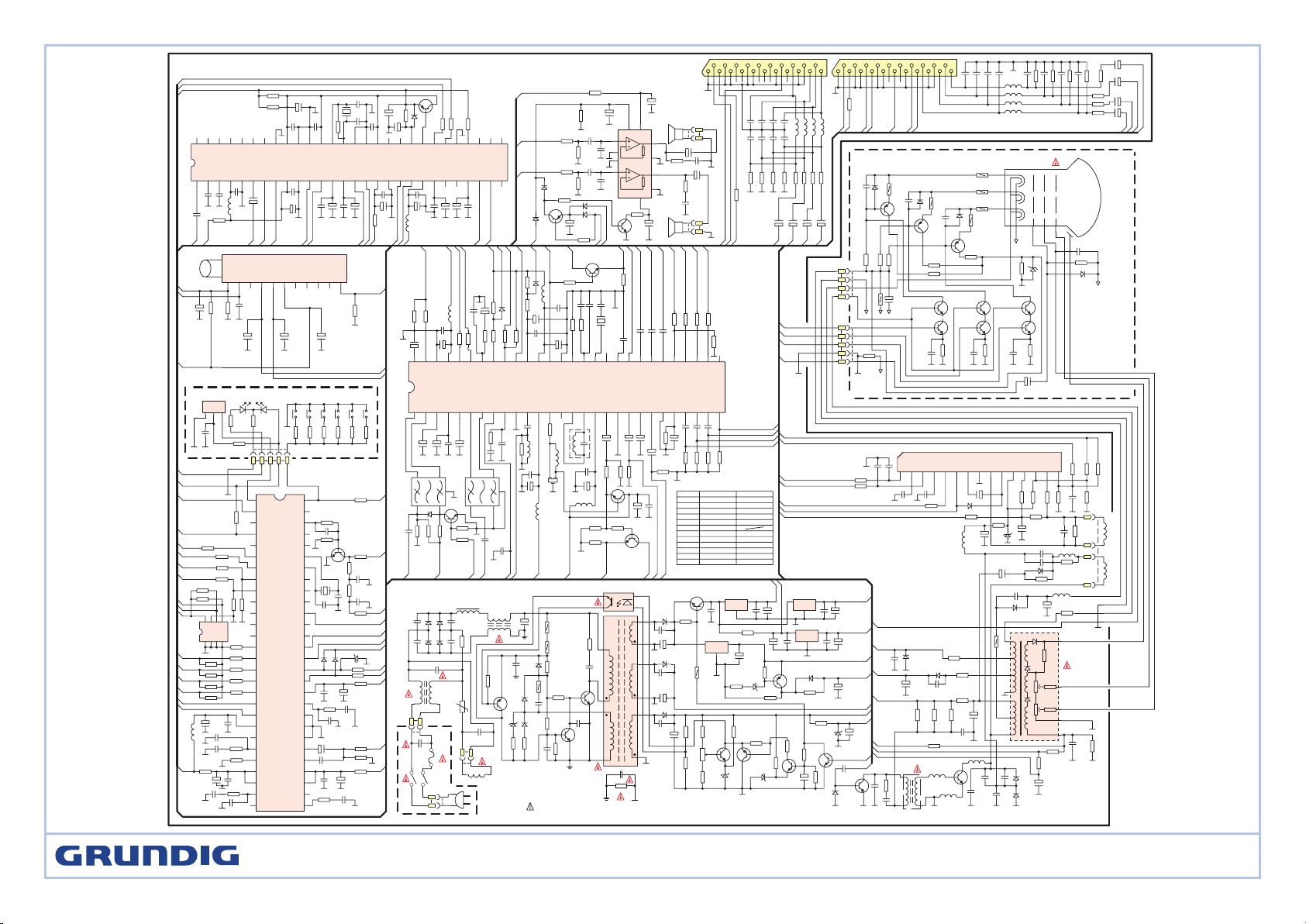
GRUNDIG TV4KS SCHEMATIC DIAGRAM
+
C607
220u/400V
D606
2
R625
6.8
D616
1N4148
D605
2
R624
39
D603
D604
T611
R013
100K
5
R633 22
+
C645 2200u/25V
D635
RU4YX
C637
470P
C303
0.1u
C304
0.68u
D302 1N4007
R324
68K
C307
1000p
R314
10K
R335
100
R322
100
C804
0.1u
C803
0.22u
C805
0.1u
R802
22
+
C685
1u
D309
1N4148
D631
RU4AM
C631
470P
+
C641
100u/160V
R302
100
R301
100
+
C661
100u/16V
R0115.6K
R805
100
R804
100
+
C820
0.47u/16V
C003
4700p
C012
0.1u
C005 0.22u
C004
220p
R015
470
D617
ES1
D614
1N4148
R619
47
R620
120K
R621
120K
R639
22K
R635
150K
R636
6.8K
VR631
2K
D685 6.2V
D641
6.2V
R688
10K
R689
22K
R687
560K
R686
150K
C323
0.1u/250V
2
R303
8.2K
2
R305
8.2K
R306
1.5K
R153
75
C301
47p
C302
47p
5
8
2
3
9
13
16
17
9
15
R637
180K
+
C639
470u/16V
+
C675
47u/16V
+
C656
220u/16V
Q683
B892
R317 1K
2
R304
8.2K
R806
4.7K
AC230V
50Hz
SW601
T3.15A 250V
F601
Q613
2SC4429
C616
1000p 2KV
C617
0.015u
Q612
2SC3807
R622
15K
R626
2.2K
C615
0.01u
R615
22K
C614
0.1u
C613
4700p
R617
1K
R623
2.7K
D619
11V
Q611
2SA1015
R611
5.6K
IC601
H11A817
T603
PFC COIL
C603C605
C606 C604
5
R602
3.9
C602
0.22u 250V
T602
ET2868
T601
ET2868
XP600
XS600
XS600A
C608
0.22u 400V
XS601
L601
DEGAUSSING COIL
C629
2200p 400V
R629
8.2M 1/2W
C603-C606 D603-D607
1000p 1KV RM11C
C013
22p
+
C635
1000u/35V
V in
GND
V out
IC605
7805
R685
15K
R655
1K
C651
0.1u
V in
GND
V out
IC606
7812
C657
0.1u
V in
GND
V out
IC603
7808
C674
0.1u
C658
0.1u
V in
GND
V out
IC604 7805
C671
0.1u
1
R638
68K
Q631
2SC1815
Q686
2SA1015
Q685
2SC1815
Q682
2SC1815
Q002
2SA1015
D001
1N4148
R014
4.7K
+
C006
1u/50V
R016
270
50V
2
R640
15K
D626
uPC574
+
C659
1uF/50V
+12V
V MUTE
+8V
+5V-1
+33V
STD BY
RST
+5V
+25V
+140V
C326
0.1u
H OUT
Q301
2SD2688
C325
330p
500V
T301
JDT1906
Q302
2SC5296
SCL
OSD R
MCFM
OSD G
JTCK
AVDD3
JTD0
TEST0
ESCR
VDD
WSCF
OSD FB
SDA
OSD B
DATA PRT
NC
S1
S0
TV /AV
SCART2 ID
SCART1 ID
SERVICE
STD BY
NC
MUTE
NC
RESET
IR IN
1
2
3
4
5
6
7
8
9
10
11
12
13
14
15
16
17
18
19
20
21
22
23
24
25
26
27
92
82
30
31
32
33
34
35
36
37
38
39
40
41
42
43
44
45
46
47
48
49
50
51
52
53
54
55
56
TXCF
CVBS0
AVDD2
JTMS
WSS
TXT VIN
AGND
GND
JTRET0
PXFM
AVDD1
H SYNC
V SYNC
BSW1
BSW2
PIF SW
NC
SIF SW
NC
VLIN PWM
VOL PWM
OSC
OSC
STDBY LED
STDBY LED
VT
NC
KB IN
IC001 ST92195
+
C010
47u/16V
R017 10
R019 6.8K
C008
0.1u
+
C009
100u/16V
L001
10uH
R0341K
R02310K
+5V
SCL
SDA
OSD FB
OSD R
OSD G
OSD B
R021 15K
C023
2200p
C022
0.1u
+
C011
47u/16V
C021
82p
+
C019
0.47u/50V
R04110
C036
22p
R039 5.6K
C035
4700p
C033
0.1u
+
C034
47u/16V
R04310
D004
1N4148
D005
1N4148
D006
5.1V
R090 1K
R049 5.6K
R002 10K
Q001
2N3904
R012 33K
X001
4MHz
C014
39p
C015
39p
R001
33K
R004 33K
C002
0.1u
R003
33K
VT
+33V
SIF SW
BSW2
BSW1
+5V
V SYNC
SC
+5V
TXT
+5V
R071 10K
+5V
L802
10uH
C807
0.1u
+
C806
10u/16V
C810
0.1u
+
C808
10u/16V
C811
0.1u
+
C809
10u/16V
AO2R
VDDA
LSR
AI2R
SW
BGAP
VERFA
LSL
AL3R
VDDH
AI3L
GNDAH
AO2L
AI2L
VMC2
VMC1
AI1R
AI1L
GNDC
VDCC
AO1R
AO1L
MONOIN
GNDIF
VDDIF
VERFIF
VTOP
SIF
1 2 3 4 5 6 7 8 9 10 11 12 13 14 15 16 17 18 19 20 21 22 23 24 25 26 27 28
2930
3132
33
34
35363738
39
404142
4344
45
464748
495051
525354
55
56
HPL
HPR
GNDSA
HPD
ADR
SCL
SAD
REG
RESET
SYSCK
MCK
VDD1
GND1
GNDSP
XTI
XTO
VDDP
GNDP
GND2
VDD2
CKTST
SD0
ST
WS
SCK
BUS1
BUS0
IRQ
IC801
STV8216
C812
0.1u
+
C813
10u/16V
R803
330
C818 0.1u
+
C819
10u/16V
C816
0.1u
+
C817
10u/16V
C814
0.1u
+
C815
10u/16V
L803
10uH
+
C827
47u/16V
C821
0.1u
X801
27MHz
C82322p
C822
22p
R807
270K
C824
0.1u
C826
0.1u
+
C825
10u/16V
VCC
BS1
BS2
AGC
VT
IF
831 54 6 7 110192
TUNER
C205
0.1u
R203
4.7K
R202
27K
+
C202
47u/16V
+
C203
47u/16V
R201
100
+8V
+5V
SIF
AOL1
AOR2
AI1L
AI1R
AI2R
AI2L
+8V
AGC
VT
+5V-1
BSW2
BSW1
+
C206
22u/16V
+
C201
47u/16V
+5V-1
SDA
SCL
XS001
+5V
+8V
CVBS IN2
VCC2
R EXT
PIF LC2
FB EXT
B EXT
Y/CVBS IN3
G EXT
APRBSCHR
CVBS IN1
GND2
PIF LC1
EXTAUDIAIN
INTCVBSOUT
VCC IF
AM/FM OUT
GND IF
IF PLL
AGC OUT
PIF IN2
PIF IN1
AGCPIFCAP
VREF IF
AGCSIFCAP
SIF IN2
SIF IN1
1 2 3 4 5 6 7 8 9 10 11 12 13 14 15 16 17 18 19 20 21 22 23 24 25 26 27 28
2930
3132
33343536
3738394041424344454647484950515253545556
NC
B OUT
G OUT
R OUT
ICAT
OSD B
OSD G
OSD R
OSD FB
XTAL3
XTAL2
XTAL1
CLPF
V AMP
GND1
CVBSOUT
VCC1
BCL
VERT
H OUT
LFB
SLPF
SCL
SDA
VCC D
GND D
AUDIO OUT
FM CAP
IC101
STV2248
C153
0.1u
C152
0.1u
C151
0.1u
R15475R15575R156
75
+
C125
1u/50V
R128
330K
+
C425
1u/50V
R418
75
+
C117
1u/50V
+
C426
1u/50V
R420
75
+
C118
1u/50V
R123
1K
R124
1K
Q102
2SC1815
T101
7K011
+
C133
470u/16V
C119
0.1u
L102
10uH
+
C110
47u/16V
C111
0.1u
R119
150
L103
10uH
CF102
5.5MHz
C103
0.1u
+
C121
47u/16V
L101
10uH
C801
47p
L801
10uH
R801560
C108
1000p
R121
150
C106
0.33u
+
C109
1u/50V
+
C123
10u/16V
C124
0.022u
+
C122
1u/50V
1 2
3
45
K3953M
SAW101
1 2
3
4
5
SAW102
K9650M
R131
470
R132
470
R133
470
R135
1K
C129
0.1u
X102
4.43
C161
15p
R129 56K
R028
1K
R027
1K
R026
1K
R025 2.7K
R030
1.5K
R0241.5K
C126
0.1u
C127
0.1u
C128
0.1u R134
47K
C138 4700p
R136
27K
C137 0.1u
R139
2.2K
R146
2.2K
R148
100
R147
100
+
C135
1u/50V
+
C132
100u
C134
0.1u
L104
10uH
R138
2.2K
R145
8.2K
D103
1N4148
R137
15K
+
C142
2.2u/50V
C143
4700p
MHz
16V
ABL
TXT
VSYNC
H OUT
SC
+8V
SCL
SDA
+5V-1
OSD FB
OSD R
OSD G
OSD B
ICAT
R OUT
G OUT
B OUT
FBI
RI
GI
BI
+5V-1
+8V
Q103
2SC1815
R111
470
R112
1K
R113
560
V OUT1
+8V
V IN1
V IN2
SIF
+
C305
100u/35V
R311
220K
R320
2.2K
R313
15K
R312
100K
V CIOL
2
R323
0.51
2
R336
470
C308
0.033u
+
C306
1000u/16V
2
R331 10
D301
43V
2
R329
4.7
+
C310
4.7u/160V
H COIL
L305 35uH
1
R309 1K
2
R308 10K
D305
RGP10G
C312
0.027u/400V
C311
0.27u/400V
+
C309
1u/250V
L304
1mH
T302 BSC27-4848FD
C316
220p
L302
0.2uH
C313
8200p
C315
0.027u
C314
4700p
D307
BY228
D306
RGP15J
1.6KV
1.6KV
400V
2KV
C317
0.039u
R316
1
D308
RGP15J
1
R310
1
D303
RGP15J
C322
220p/500V
1
R318 1K
D304
1N4148
+
C320
1000u/35V
3
R315 4.7
2
R307
1
C318 220p/500V
+
C319
10u/250V
L306
100uH
+
C321
100u/100V
R325
10K
R321
8.2K
R319
22K
ABL
+24V
+140V
+24V
SC
R149
10K
+
C146
4.7u/50V
ABL-V
+12V
XS302
SCL
SDA
V SYNC
+24V
+12V
R515
2.2K
R510
2.2K
R505
2.2K
2
R507 15K
R521
150K
R504
1.2K
R509
1.2K
R514
1.2K
R503
10K
R506
390
C503
470p
R501
390
C501
470p
2
R502 15K
2
R512 15K
D507
5.1V
R516
47K
D506
1N4007
C506
220p
Q509
BF423
D504
1N4007
C504
220p
Q503
BF423
D502
1N4007
C502
220p
Q506
BF423
R50810K
R51310K
Q502
2SC2688
Q501
2SC1815
Q505
2SC2688
Q504
2SC1815
Q508
2SC2688
Q507
2SC1815
R511 390
C505
470p
+
C507
1u/250V
R074
3.9K
R073
2.2K
R072
1K
R077
9.1K
SW002
P-
SW001P+SW004V-SW005
MENU
D001A
HFT505M
R015
120
R015A
180
R076 10
C040
0.1u
I R
IC011
HS0038
IF
+12V
ABL-V
KB
KG
KR
CRT
C511
2200p/2KV
XP502
XP501XS101
HV
FOCUS
SCREEN
OUT L
OUT R
ICAT
R OUT
G OUT
B OUT
ROLO
RILISW
BI
VI
VO
FBI
GIRI
123456789101112131 4151617
1819
2021
SCART1
RO
LO
RILI
SW
BI
VI
VO
FBI
GIRI
12345678910111213141516171819
2021
SCART2
C406
1000p
C401
1000p
C405
1000p
C402
1000p
L403 8.2uH
L402 8.2uH
L404 8.2uH
L401 8.2uH
C407
1000p
C404
1000p
C408
1000p
C403
1000p
R403 100K
R408 100K
R404 100K
R407 100K
R401 220
R406 220
R402 220
R405 220
R409
68
V IN2
V OUT2
AI1R
AI1L
AOR2
AOL2
L407 8.2uH
L406 8.2uH
L408 8.2uH
L405 8.2uH
C419
1000p
C416
1000p
C420
1000p
C415
1000p
C422
1000p
R415
100K
R411
100K
R416
100K
R410
100K
C418
1000p
C421
1000p
C417
1000p
R414
220
R413 220
R417 220
R412 220
V IN1
R419
68
V OUT1
FBIRIGIBISCART1 ID
SCART2 ID
AOL1
AOR1
AI2L
AI2R
1. IS MARK OF CRITICAL COMPONENT
2.SUBJECT TO CHANGE WITHOUT NOTICE
C107
0.1u
AGC
+
C410
1u 50V
+
C411
1u 50V
+
C409
1u 50V
+
C412
1u 50V
+
C423 1u 50V
+
C413
1u 50V
+
C414
1u 50V
+
C424
1u 50V
SCL
CRAMP
SDA
CHOLD
SYNC
VCC
FLYBACK
GND
OUT
VOPS
EWOUT
SENS2
EWSENS
SENS1
BREATH
1 2 3 4 5 6 7 8 9 10 11 12 13 14 15
IC301 STV9306
R81368
R814
68
D101
1N41
R117
6.8K
R118
2.2K
R116
2.2K
Q101
2SC1815
R115
10K
R114
22K
C104
0.1u
C105
0.1u
48
SIF SW
IF
IF
+8V
L303
0.2uH
L301
0.2uH
C139
0.1u
L105
10uH
+
C145
4.7u
R144
56K
R143
2.2K
D102
1N4148
C141
0.1u
+
C131
470u
16V
C802
56p
R005 6.8K
R007
12K
R006
12K
R0104.7K
R060 6.8K
+5V
SCL
SDA
SCART2 ID
SCART1 ID
+5V
A0A1A2
GND SDA
SCL
VCC
WC
IC002
24C08
R0082.7K
R0092.7K
R684
150K
Q801
2SA1015
R808
220K
D801
1N4148
R522
2.2M
+
C512
1u/250V
D509
1N4007
R520 22
C330
47p
R075
6.2K
SW003
V+
R078 22K
SW006
TV/AV
AOR2
AOL2
R157
1K
Q401
2SC1815
R423
560
V OUT2
+8V
R020
4.7K
MUTE
RST
R0366.8K
STD BY
5
1
10 13
14
9
12
15
8
11
7
IC701
TDA7495SSA
C703A
2200p
C702
0.1u
C704
2200p
C701
0.1u
R812
4.7K
R811
4.7K
R809
6.8K
R810
6.8K
+
C707
1u/50V
+
C710
1000u/35V
D707
1N4148
+
C715
220u
R710
22K
D706
1N4148
Q702
2SA1015
16V
OUT R
OUT L
V MUTE
MUTE
2
R713 1
+25V
R711
4.7
C714
0.1u
+
C711
470u/25V
XS701
L SPK
R712
4.7
C713 0.1u
+
C712
470u/25V
XS701
R SPK
D705
1N4148
+
C706
470u
D708 1N4148
+5V-1
R709
100K
+
C828
1u/50V
MONO IN
R110
10K
MONO IN
R120
10K
Q701
2SC1815
R714
4.7K
R707
100
28" 29"
LOCATION
R325
R636
R323
R315
R329
C312
C315
C311
C314
L305
T604
T302
7.5K 1/6W
0805 SMD 6.8K
0.51ohm 1W
3.3ohm 3W
4.7ohm 2W
0.027uF 400V
0.027uF 400V
0.27uF 400V
4700p 1.6KV
35uH
BCK-65-10L2
BSC25-4849FD BSC25-4848FD
10K 1/6W
0805 SMD 7.5K
0.68ohm 1W
2.2ohm 2W
15ohm 2W
0.022uF 400V
0.33uF 400V
6800p 1.6KV
29uH
BCK-65-10L3
STF 72-1002/7 Text, ST 70-1002/7 Text
Page 3
C601A
0.22u 250V
RT601
MZ72-18
D634
RU4YX
C634
390P
D002
3.9V
C031 47p
C001 0.1u
R033 1K
R031 1K
R029 1K
R037 39K
R018 5.6K
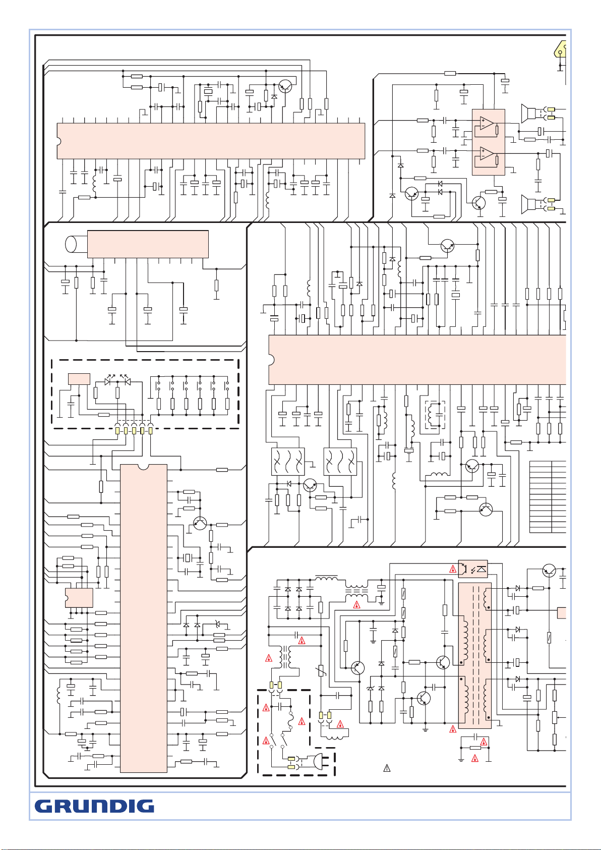
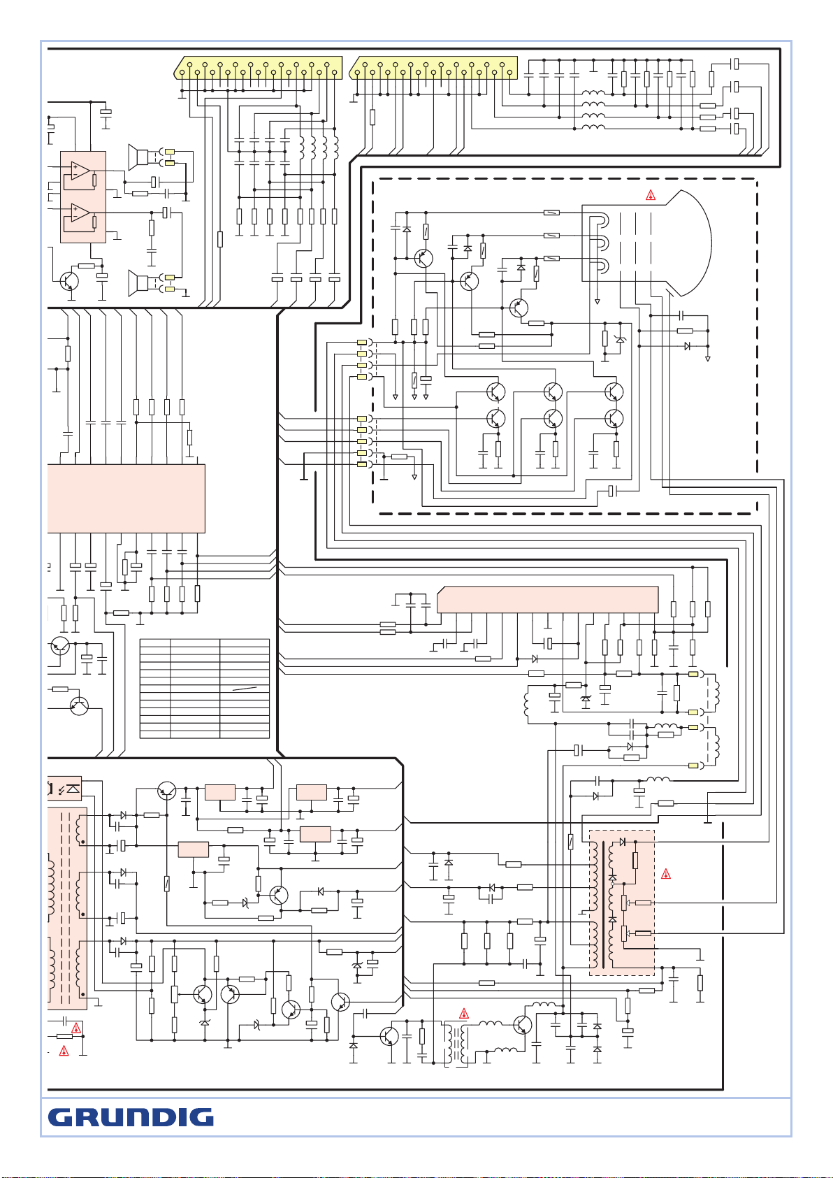
GRUNDIG TV4KS SCHEMATIC DIAGRAM
+
C607
220u/400V
D606
2
R625
6.8
D616
1N4148
D605
2
R624
39
D603
D604
T611
5
R633 22
+
C645 2200u/25V
D635
RU4YX
C637
470P
C804
0.1u
C803
0.22u
C805
0.1u
R802
22
D631
RU4AM
C631
470P
+
C641
100u/160V
+
C661
100u/16V
R011 5.6K
R805
100
R804
100
+
C820
0.47u/16V
C003
4700p
C012
0.1u
C005 0.22u
C004
220p
R015
470
D617
ES1
D614
1N4148
R619
47
R620
120K
R621
120K
R639
22K
R635
150K
R636
6.8K
VR631
2K
D685 6.2V
D641
6.2V
R689
22K
R153
75
5
8
2
3
9
13
16
17
9
15
R637
180K
+
C639
470u/16V
+
C656
220u/16V
Q683
B892
R806
4.7K
AC230V
50Hz
SW601
T3.15A 250V
F601
Q613
2SC4429
C616
1000p 2KV
C617
0.015u
Q612
2SC3807
R622
15K
R626
2.2K
C615
0.01u
R615
22K
C614
0.1u
C613
4700p
R617
1K
R623
2.7K
D619
11V
Q611
2SA1015
R611
5.6K
IC601
H11A817
T603
PFC COIL
C603C605
C606 C604
5
R602
3.9
C602
0.22u 250V
T602
ET2868
T601
ET2868
XP600
XS600
XS600A
C608
0.22u 400V
XS601
L601
DEGAUSSING COIL
C629
2200p 400V
R629
8.2M 1/2W
C603-C606 D603-D607
1000p 1KV RM11C
C013
22p
+
C635
1000u/35V
V in
GND
V out
IC605
7805
R685
15K
R655
1K
C651
0.1u
V in
GND
V out
IC606
7812
C657
0.1u
C658
1
R638
68K
Q631
2SC1815
Q686
2SA1015
Q685
2SC1815
Q002
2SA1015
R014
4.7K
R016
270
+12V
V MUTE
SCL
OSD R
MCFM
OSD G
JTCK
AVDD3
JTD0
TEST0
ESCR
VDD
WSCF
OSD FB
SDA
OSD B
DATA PRT
NC
S1
S0
TV /AV
SCART2 ID
SCART1 ID
SERVICE
STD BY
NC
MUTE
NC
RESET
IR IN
1
2
3
4
5
6
7
8
9
10
11
12
13
14
15
16
17
18
19
20
21
22
23
24
25
26
27
92
82
30
31
32
33
34
35
36
37
38
39
40
41
42
43
44
45
46
47
48
49
50
51
52
53
54
55
56
TXCF
CVBS0
AVDD2
JTMS
WSS
TXT VIN
AGND
GND
JTRET0
PXFM
AVDD1
H SYNC
V SYNC
BSW1
BSW2
PIF SW
NC
SIF SW
NC
VLIN PWM
VOL PWM
OSC
OSC
STDBY LED
STDBY LED
VT
NC
KB IN
IC001 ST92195
+
C010
47u/16V
R017 10
R019 6.8K
C008
0.1u
+
C009
100u/16V
L001
10uH
R034 1K
R023 10K
+5V
SCL
SDA
OSD FB
OSD R
OSD G
OSD B
R021 15K
C023
2200p
C022
0.1u
+
C011
47u/16V
C021
82p
+
C019
0.47u/50V
R041 10
C036
22p
R039 5.6K
C035
4700p
C033
0.1u
+
C034
47u/16V
R043 10
D004
1N4148
D005
1N4148
D006
5.1V
R090 1K
R049 5.6K
R002 10K
Q001
2N3904
R012 33K
X001
4MHz
C014
39p
C015
39p
R001
33K
R004 33K
C002
0.1u
R003
33K
VT
+33V
SIF SW
BSW2
BSW1
+5V
V SYNC
SC
+5V
TXT
+5V
R071 10K
+5V
L802
10uH
C807
0.1u
+
C806
10u/16V
C810
0.1u
+
C808
10u/16V
C811
0.1u
+
C809
10u/16V
AO2R
VDDA
LSR
AI2R
SW
BGAP
VERFA
LSL
AL3R
VDDH
AI3L
GNDAH
AO2L
AI2L
VMC2
VMC1
AI1R
AI1L
GNDC
VDCC
AO1R
AO1L
MONOIN
GNDIF
VDDIF
VERFIF
VTOP
SIF
1 2 3 4 5 6 7 8 9 10 11 12 13 14 15 16 17 18 19 20 21 22 23 24 25 26 27 28
2930
3132
33
34
35
36
3738
39
404142
4344
45
464748
49
50
51
525354
55
56
HPL
HPR
GNDSA
HPD
ADR
SCL
SAD
REG
RESET
SYSCK
MCK
VDD1
GND1
GNDSP
XTI
XTO
VDDP
GNDP
GND2
VDD2
CKTST
SD0
ST
WS
SCK
BUS1
BUS0
IRQ
IC801
STV8216
C812
0.1u
+
C813
10u/16V
R803
330
C818 0.1u
+
C819
10u/16V
C816
0.1u
+
C817
10u/16V
C814
0.1u
+
C815
10u/16V
L803
10uH
+
C827
47u/16V
C821
0.1u
X801
27MHz
C823 22p
C822
22p
R807
270K
C824
0.1u
C826
0.1u
+
C825
10u/16V
VCC
BS1
BS2
AGC
VT
IF
831 54 6 7 110192
TUNER
C205
0.1u
R203
4.7K
R202
27K
+
C202
47u/16V
+
C203
47u/16V
R201
100
+8V
+5V
SIF
AOL1
AOR2
AI1L
AI1R
AI2R
AI2L
+8V
AGC
VT
+5V-1
BSW2
BSW1
+
C206
22u/16V
+
C201
47u/16V
+5V-1
SDA
SCL
XS001
+5V
+8V
CVBS IN2
VCC2
R EXT
PIF LC2
FB EXT
B EXT
Y/CVBS IN3
G EXT
APRBSCHR
CVBS IN1
GND2
PIF LC1
EXTAUDIAIN
INTCVBSOUT
VCC IF
AM/FM OUT
GND IF
IF PLL
AGC OUT
PIF IN2
PIF IN1
AGCPIFCAP
VREF IF
AGCSIFCAP
SIF IN2
SIF IN1
1 2 3 4 5 6 7 8 9 10 11 12 13 14 15 16 17 18 19 20 21 22 23 24 25 26 27 28
2930
3132
33343536
37383940
41
424344454647484950515253545556
NC
B OUT
G OUT
R OUT
ICAT
OSD B
OSD G
OSD R
OSD FB
XTAL3
XTAL2
XTAL1
CLPF
V AMP
GND1
CVBSOUT
VCC1
BCL
VERT
H OUT
LFB
SLPF
SCL
SDA
VCC D
GND D
AUDIO OUT
FM CAP
IC101
STV2248
C153
0.1u
C152
0.1u
C151
0.1u
R15475R155
75
R156
75
+
C125
1u/50V
R128
330K
+
C425
1u/50V
R418
75
+
C117
1u/50V
+
C426
1u/50V
R420
75
+
C118
1u/50V
R123
1K
R124
1K
Q102
2SC1815
T101
7K011
+
C133
470u/16V
C119
0.1u
L102
10uH
+
C110
47u/16V
C111
0.1u
R119
150
L103
10uH
CF102
5.5MHz
C103
0.1u
+
C121
47u/16V
L101
10uH
C801
47p
L801
10uH
R801560
C108
1000p
R121
150
C106
0.33u
+
C109
1u/50V
+
C123
10u/16V
C124
0.022u
+
C122
1u/50V
1 2
3
45
K3953M
SAW101
1 2
3
4
5
SAW102
K9650M
R131
470
R132
470
R133
470
R135
1K
C129
0.1u
X102
4.43
C161
15p
R129 56K
R028
1K
R027
1K
R026
1K
R025 2.7K
R030
1.5K
R024 1.5K
C126
0.1u
C127
0.1u
C128
0.1u R134
47K
C138 4700p
R136
27K
C137 0.1u
R139
2.2K
R146
2.2K
R148
100
R147
100
+
C135
1u/50V
+
C132
100u
C134
0.1u
L104
10uH
R138
2.2K
R145
8.2K
D103
1N4148
R137
15K
+
C142
2.2u/50V
C143
4700p
MHz
16V
ABL
TXT
VSYNC
H OUT
SC
+8V
SCL
SDA
+5V-1
OSD FB
OSD R
OSD G
OSD B
ICAT
R OUT
G OUT
B OUT
FBI
RI
GI
BI
+5V-1
+8V
Q103
2SC1815
R111
470
R112
1K
R113
560
V OUT1
+8V
V IN1
V IN2
SIF
SCL
SDA
V SYNC
+24V
+12V
R074
3.9K
R073
2.2K
R072
1K
R077
9.1K
SW002
P-
SW001
P+
SW004V-SW005
MENU
D001A
HFT505M
R015
120
R015A
180
R076 10
C040
0.1u
I R
IC011
HS0038
IF
+12V
ABL-V
OUT L
OUT R
ICAT
R OUT
G OUT
B OUT
SW
VI
VO
FBI
GIRI
89
10111213141516171819
2021
SCART2
C406
1000p
C401
1000p
1000p
C402
1000p
1000p
C404
1000p
C408
1000p
C403
1000p
R403 100K
R408 100K
R404 100K
R409
68
V IN2
V OUT2
AI1L
SCART2 ID
1. IS MARK OF CRITICAL COMPONENT
2.SUBJECT TO CHANGE WITHOUT NOTICE
C107
0.1u
AGC
+
C410
1u 50V
R813 68
R814
68
D101
1N41
R117
6.8K
R118
2.2K
R116
2.2K
Q101
2SC1815
R115
10K
R114
22K
C104
0.1u
C105
0.1u
48
SIF SW
IF
IF
+8V
C139
0.1u
L105
10uH
+
C145
4.7u
R144
56K
R143
2.2K
D102
1N4148
C141
0.1u
+
C131
470u
16V
C802
56p
R005 6.8K
R007
12K
R006
12K
R010 4.7K
R060 6.8K
+5V
SCL
SDA
SCART2 ID
SCART1 ID
+5V
A0A1A2
GND SDA
SCL
VCC
WC
IC002
24C08
R008 2.7K
R009 2.7K
R684
150K
Q801
2SA1015
R808
220K
D801
1N4148
R075
6.2K
SW003
V+
R078 22K
SW006
TV/AV
AOR2
AOL2
R157
1K
Q401
2SC1815
R423
560
V OUT2
+8V
R020
4.7K
MUTE
RST
R036 6.8K
STD BY
5
1
10 13
14
9
12
15
8
11
7
IC701
TDA7495SSA
C703A
2200p
C702
0.1u
C704
2200p
C701
0.1u
R812
4.7K
R811
4.7K
R809
6.8K
R810
6.8K
+
C707
1u/50V
+
C710
1000u/35V
D707
1N4148
+
C715
220u
R710
22K
D706
1N4148
Q702
2SA1015
16V
OUT R
OUT L
V MUTE
MUTE
2
R713 1
+25V
R711
4.7
C714
0.1u
+
C711
470u/25V
XS701
L SPK
R712
4.7
C713 0.1u
+
C712
470u/25V
XS701
R SPK
D705
1N4148
+
C706
470u
D708 1N4148
+5V-1
R709
100K
+
C828
1u/50V
MONO IN
R110
10K
MONO IN
R120
10K
Q701
2SC1815
R714
4.7K
R707
100
28" 29"
LOCATION
R325
R636
R323
R315
R329
C312
C315
C311
C314
L305
T604
T302
7.5K 1/6W
0805 SMD 6.8K
0.51ohm 1W
3.3ohm 3W
4.7ohm 2W
0.027uF 400V
0.027uF 400V
0.27uF 400V
4700p 1.6KV
35uH
BCK-65-10L2
BSC25-4849FD BSC25-4848FD
10K 1/6W
0805 SMD 7.5K
0.68ohm 1W
2.2ohm 2W
15ohm 2W
0.022uF 400V
0.33uF 400V
6800p 1.6KV
29uH
BCK-65-10L3
STF 72-1002/7 Text, ST 70-1002/7 Text
Page 4
D634
RU4YX
C634
390P
D002
3.9V
+
C632
47u/16V
C324
330p/500V
T611
R013
100K
5
R633 22
+
C645 2200u/25V
D635
RU4YX
C637
470P
C303
0.1u
C304
0.68u
D302 1N4007
R324
68K
C307
1000p
R314
10K
R335
100
R322
100
+
C685
1u
D309
1N4148
D631
RU4AM
C631
470P
+
C641
100u/160V
R302
100
R301
100
+
C661
100u/16V
R015
470
R639
22K
R635
150K
R636
6.8K
VR631
2K
D685 6.2V
D641
6.2V
R688
10K
R689
22K
R687
560K
R686
150K
C323
0.1u/250V
2
R303
8.2K
2
R305
8.2K
R306
1.5K
R153
75
C301
47p
C302
47p
9
13
16
17
9
15
R637
180K
+
C639
470u/16V
+
C675
47u/16V
+
C656
220u/16V
Q683
B892
R317 1K
2
R304
8.2K
IC601
H11A817
R629
8.2M 1/2W
+
C635
1000u/35V
V in
GND
V out
IC605
7805
R685
15K
R655
1K
C651
0.1u
V in
GND
V out
IC606
7812
C657
0.1u
V in
GND
V out
IC603
7808
C674
0.1u
C658
0.1u
V in
GND
V out
IC604 7805
C671
0.1u
1
R638
68K
Q631
2SC1815
Q686
2SA1015
Q685
2SC1815
Q682
2SC1815
Q002
2SA1015
D001
1N4148
R014
4.7K
+
C006
1u/50V
R016
270
50V
2
R640
15K
D626
uPC574
+
C659
1uF/50V
+12V
V MUTE
+8V
+5V-1
+33V
STD BY
RST
+5V
+25V
+140V
C326
0.1u
H OUT
Q301
2SD2688
C325
330p
500V
T301
JDT1906
Q302
2SC5296
CVBS IN2
R EXT
FB EXT
B EXT
Y/CVBS IN3
G EXT
APRBSCHR
GND2
2930
3132
33343536
37383940
NC
B OUT
G OUT
R OUT
ICAT
OSD B
OSD G
OSD R
OSD FB
XTAL3
C153
0.1u
C152
0.1u
C151
0.1u
R154
75
R15575R156
75
+
C125
1u/50V
R128
330K
+
C425
1u/50V
R418
75
+
C117
1u/50V
+
C426
1u/50V
R420
75
1u/50V
R123
1K
R124
1K
2SC1815
+
C110
47u/16V
C111
0.1u
R131
470
R132
470
R133
470
R135
1K
C129
0.1u
C126
0.1u
C127
0.1u
C128
0.1u R134
47K
OSD FB
OSD R
OSD G
OSD B
ICAT
R OUT
G OUT
B OUT
FBI
RI
GI
BI
Q103
2SC1815
R112
1K
+8V
V IN1
V IN2
+
C305
100u/35V
R311
220K
R320
2.2K
R313
15K
R312
100K
V CIOL
2
R323
0.51
2
R336
470
C308
0.033u
+
C306
1000u/16V
2
R331 10
D301
43V
2
R329
4.7
+
C310
4.7u/160V
H COIL
L305 35uH
1
R309 1K
2
R308 10K
D305
RGP10G
C312
0.027u/400V
C311
0.27u/400V
+
C309
1u/250V
L304
1mH
T302 BSC27-4848FD
C316
220p
L302
0.2uH
C313
8200p
C315
0.027u
C314
4700p
D307
BY228
D306
RGP15J
1.6KV
1.6KV
400V
2KV
C317
0.039u
R316
1
D308
RGP15J
1
R310
1
D303
RGP15J
C322
220p/500V
1
R318 1K
D304
1N4148
+
C320
1000u/35V
3
R315 4.7
2
R307
1
C318 220p/500V
+
C319
10u/250V
L306
100uH
+
C321
100u/100V
R325
10K
R321
8.2K
R319
22K
ABL
+24V
+140V
+24V
SC
R149
10K
+
C146
4.7u/50V
ABL-V
+12V
XS302
SCL
SDA
V SYNC
+24V
+12V
R515
2.2K
R510
2.2K
R505
2.2K
2
R507 15K
R521
150K
R504
1.2K
R509
1.2K
R514
1.2K
R503
10K
R506
390
C503
470p
R501
390
C501
470p
2
R502 15K
2
R512 15K
D507
5.1V
R516
47K
D506
1N4007
C506
220p
Q509
BF423
D504
1N4007
C504
220p
Q503
BF423
D502
1N4007
C502
220p
Q506
BF423
R508 10K
R513 10K
Q502
2SC2688
Q501
2SC1815
Q505
2SC2688
Q504
2SC1815
Q508
2SC2688
Q507
2SC1815
R511 390
C505
470p
+
C507
1u/250V
+12V
ABL-V
KB
KG
KR
CRT
C511
2200p/2KV
XP502
XP501XS101
HV
FOCUS
SCREEN
ICAT
R OUT
G OUT
B OUT
ROLO
RILISW
BI
VI
VO
FBI
GIRI
1234567891011121314151617
1819
2021
SCART1
RO
LO
RILI
SW
BI
VI
VO
FBI
GIRI
1234567
89
10111213141516171819
2021
SCART2
C406
1000p
C401
1000p
C405
1000p
C402
1000p
L403 8.2uH
L402 8.2uH
L404 8.2uH
L401 8.2uH
C407
1000p
C404
1000p
C408
1000p
C403
1000p
R403 100K
R408 100K
R404 100K
R407 100K
R401 220
R406 220
R402 220
R405 220
R409
68
V IN2
V OUT2
AI1R
AI1L
AOR2
AOL2
L407 8.2uH
L406 8.2uH
L408 8.2uH
L405 8.2uH
C419
1000p
C416
1000p
C420
1000p
C415
1000p
C422
1000p
R415
100K
R411
100K
R416
100K
R410
100K
C418
1000p
C421
1000p
C417
1000p
R414
220
R413 220
R417 220
R412 220
V IN1
R419
68
V OUT1
FBI
RI
GIBISCART1 ID
SCART2 ID
AOL1
AOR1
AI2L
AI2R
+
C410
1u 50V
+
C411
1u 50V
+
C409
1u 50V
+
C412
1u 50V
+
C423 1u 50V
+
C413
1u 50V
+
C414
1u 50V
+
C424
1u 50V
SCL
CRAMP
SDA
CHOLD
SYNC
VCC
FLYBACK
GND
OUT
VOPS
EWOUT
SENS2
EWSENS
SENS1
BREATH
1 2 3 4 5 6 7 8 9 10 11 12 13 14 15
IC301 STV9306
L303
0.2uH
L301
0.2uH
R684
150K
R522
2.2M
+
C512
1u/250V
D509
1N4007
R520 22
C330
47p
R423
560
V OUT2
5
1
10 13
14
9
12
15
8
11
7
IC701
TDA7495SSA
+
+
C710
1000u/35V
R711
4.7
C714
0.1u
+
C711
470u/25V
XS701
L SPK
R712
4.7
C713 0.1u
+
C712
470u/25V
XS701
R SPK
+
C706
470u
Q701
2SC1815
R707
100
28" 29"
LOCATION
R325
R636
R323
R315
R329
C312
C315
C311
C314
L305
T604
T302
7.5K 1/6W
0805 SMD 6.8K
0.51ohm 1W
3.3ohm 3W
4.7ohm 2W
0.027uF 400V
0.027uF 400V
0.27uF 400V
4700p 1.6KV
35uH
BCK-65-10L2
BSC25-4849FD BSC25-4848FD
10K 1/6W
0805 SMD 7.5K
0.68ohm 1W
2.2ohm 2W
15ohm 2W
0.022uF 400V
0.33uF 400V
6800p 1.6KV
29uH
BCK-65-10L3
STF 72-1002/7 Text, ST 70-1002/7 Text
Page 5

STF 72-1002/7 Text, ST 70-1002/7 Text
Page 6

STF 72-1002/7 Text, ST 70-1002/7 Text
Page 7

STF 72-1002/7 Text, ST 70-1002/7 Text
Page 8

SECIFICATION
SYSTEM ..........................PAL,SECAM, B/G, D/K NIACAM STEREO
POWER INPUT
POWER CONSUMPTION
AERIAL IMPEDANCE
TUNER ......................................VOLTAGE SYNTHESIZER TUNING
RECEIVING CHANNELS
...................................................................................VHF-H E5-S41
.................................................................................... UHF E21-E69
PROGRAMME...............................MAX.99 PROGRAM MEMORIES
PICTURE TUBE
SOUND OUTPUT
AV JACKS
....................................................................AV SCART & SIDE RCA
CAUTION:
Before servicing the chassis, read the “Safely Precaution”. “X -Ray radiation Precaution” and “Product Safety Notice” in this manual.
X-RAY RADIATION PRECAUTION
1. Excessive high voltage can produce potentially hazardous X-RAY RADIATION. To Avoid such hazards the high voltage must be specified limit. The
normal value of the high voltage of this receiver is 28” 27KV 29” 30KV +/-500V under 230V AC power source. The high voltage must not exceed
32KV.
2. Each time a receiver requires servicing the high voltage should be checked following the HIGH VOLTAGE CHECK procedure in this manual. It is
recommended the reading of the high voltage be recorded as a part of the service record. It is important to use an accurate and reliable high voltage
meter.
3. The primary source of X -RAY RADIATION in this TV receiver is the picture tube. For continued X-RAY RADIATION protection, the replacement tube
must be exactly the same type tube as used in this TV receiver.
4. Some parts in this receiver have special safety-related characteristics for X-RAY RADIATION protection. For continued safety, parts replacement
should be undertaken only after referring the PRODUCT SAFETY NOTICE below.
.............................................AC 170-260V(50/60Hz)
..................................28” 100W 29” 120W
................................. 75 OHM UNVALANCED
............................................VHF-L E2-S10
................................................................... 28” 29”
........................................................................≥5W
...................................................................FULL SCART
SAFETY PRECAUTION
WARNING:
Service should not be attempted by anyone unfamiliar with the necessary Precautions on this receiver.
The following are the necessary precautions to be observed before servicing this chassis.
1. Since the power supply circuit of this receiver is directly connected to the AC power line. An isolation transformer should be used during any dynamic
service to avoid possible shock hazard.
2. Always discharge the picture tube anode to the CRT conductive coating before handling the picture tube. The picture tube is highly evacuated and if
broken, glass fragments will be violently expelled. Use shatterproof goggles and keep picture tube away from the unprotected body while handling.
3. When replacing a chassis in the cabinet, always be certain that all the protective devices are put back in place, such as: nonmetallic control; knobs,
insulating covers, shields, isolation resistor-capacitor, network, etc.
4. When replacing parts or circuit boards, disconnect the power cord.
5. When replacing a high voltage resistor (metal oxide resistor) on circuit board, keep the resistor APP. 10mm(1/2 in.) away from circuit board.
6. Connection wires must be kept away from components with high voltage or high temperature.
7. If any fuse in this TV receiver is blown, replace it with the FUSE specified in the chassis parts list.
8. The receiver is designed to operate with 230V(50Hz) AC mains.
PRODUCT SAFETY NOTICE
Many electrical and mechanical parts in this chassis have special safety-related characteristics are often passed unnoticed by a visual inspection and
the X-RAY RADIATON protection afforded by them cannot necessarily be obtained by using replacement components rated for higher voltage. The use
of substitute replacement parts that do not have the same safety characteristics as specified in the parts list may create shock, fire, X-RAY RADIATION
or other hazards.
STF 72-1002/7 Text, ST 70-1002/7 Text
Page 9

GENERAL ADJUSTMENT
1
5
9
-/- -
6 7 8
ⅠⅡ/
2 3 4
AUTOMATIC DEGAUSSING
An automatic degaussing coil is attached around the picture tube, degaussing the tube properly in about one second after the set is switched on. If the
receiver is moved or faced on a different direction, the power must be switched off at least 15 minutes in order that the automatic degaussing circuit
operated properly. External degaussing is necessary if the automatic degassing proves ineffective after the set is moved.
B+ ADJUSTMENT
CAUTION:
To avoid X-ray hazards and result in a nominal display width, B+ voltage must be set in the scale of 28” 140V±0.5V 29” 130V±0.5V.
1. Make sure the AC power supply is 230V, 50Hz.
2. Switch on the TV receiver, tune in an active channel.
3. Measure the voltage between C641 on Main P.C. Board by DC voltmeter.
4. Set contrast, brightness, color to maximum.
5. Adjust VR631 on Main P.C. Board for B+ 28” 140V±0.5V 29” 130V±0.5V voltage reading.
HIGH VOLTAGE CHECK
CAUTION:
There is no high voltage adjustment in this chassis, B+ voltage directly relates to the high voltage. The high voltage does not exceed 28” 27KV±500V
29”30KV±500V under any conditions.
1. Connect an accurate high voltage meter to the second anode cap of the picture tube.
2. Turn on the receiver, set brightness and contrast to minimum (Zero beam current).
3. Make sure the high voltage does not exceed 30KV±500V.
4. NO matter whether the luminance, contrast and chrominance controls are set to maximum or minimum, the high voltage must be kept under
30KV±500V.
FOCUSING
Receive a TV test pattern signal; adjust focus knob to get optimum picture, a well-defined, sharpest display in the center area of the screen.
ADJUSTMENT AND SERVICING THE CHASSIS
SERVICE MODE
To enter the service mode, a special remote control which contains an additional SERVICE key must be used. See the illustration. Press the ‘SERVICE’
key on remote control, TV will display service menu as following table 1 line by line. To select the item by using the ‘P+/P-’ keys. To adjust the value of
selected parameter by using the ‘V+/V-’ keys. To quit the service mode, press the ‘P.P.’ key on remote control when in the service mode.
Table 1
Parameter Value
Red gain
DC red
Green gain
DC green
Blue gain
DC blue
Apr threshold
Logo
Red Cutoff
Green Cutoff
32
063
32
063
32
063
12
6
31
31
To enter the table 2, press the ‘OK’ key on the remote control
for the first time when in the service mode.
Table 2
Parameter Value
Tuner AGC
H POS 50
VPOS 50
VAMP 50
VLIN 50
H POS 60
VPOS 60
VAMP 60
VLIN 60
Bright max
Bright min
Sub tint
VCO coarse
VCO fine
VCO coarse L1
VCO fine L1
22
32
8
47
31
32
10
53
31
63
00
32
05
063
05
080
STF 72-1002/7 Text, ST 70-1002/7 Text
Page 10

To enter the table 3, press the ‘OK’ key for the second time on the remote control when in the service mode.
Table 3
Parameter Value
AGC gain
Option 1
Option 2
Option 3
Option 4
Option 5
ST Ttext
H POS OSD
V POS OSD
H POS TXT
V POS TXT
Hotel Mode
Volume Limit
Snd ST1
Snd ST2
Following are item description of OPTION in more details.
OPTION1
b7 = Over modulation (0=Disable, 1=Enable, it’s suggested to set it to 0 normally.)
b5 = P/N/S crystals application (0=2 Crystals, 1= 1 Crystals, according the quantity of cristal used for color decoding in chassis.)
b4 = Cutoff Loop (0= OFF, 1=ON, it’s suggested to set it to 1 normally)
b3 = Safety_Reset(0=Active, 1=Non, it’s suggested to set it to 0 normally)
b2 = MONO IN(0 = OFF , 1= ON, Depend on the sound decoding solution used in chassis. )
b1 = Sound Demodulation ( 0 = Intercarrier/MONO, 1 =QSS/NICAM, depend on the sound decoding solution used in chassis.)
b0 = logo display(0 =OFF, 1= ON, it’s suggested to set it to 0 normally.)
00
54
00
134
027
00
00
001
01
067
04
OFF
10
79
79
OPTION2 (set to 0 by default)
b5 = HALF_CONTRAST(0 = OFF, 1=ON)
b4 = Color 6dB (0 = OFF , 1 = ON )
b3 = APR Feature (0 = ON , 1= OFF )
b2 = Black Strech (0 = ON , 1= OFF )
b1 = Auto Flesh (0 = ON , 1= OFF )
b0 = Coring ( 0 = ON , 1 = OFF )
OPTION3
b7 =SMART (0 = OFF, 1=ON, it’s suggested to set it to 1 normally)
b5 = AVL (0 = OFF, 1=ON, it’s suggested to set it to 0 normally.)
b4 = PIF overmodulation (0 = OFF, 1= ON, it’s suggested to set it to 0 normally.)
b3 = Market_France - secam LL ( 0 = OFF, 1 = ON, depend on the solution of chassis.)
b2 = Manual/Auto cutoff ( 0 = Manual, 1 = Auto cutoff, depend on the CRT for chassis. )
b1 = Mute pin low/high –to contol the mute of speaker( 0 = low, 1 = high, depend on the solution of chassis.)
OPTION4
b6 = WIDE MODE ( 0 = OFF,1=ON, it’s suggested to set it to 0 normally.)
b4 = SCART2 ( 0 = OFF,1=ON, depend on the solution of chassis.)
b3 = RGB ( 0 = OFF, 1= ON, depend on the solution of chassis.)
b2 = SVHS ( 0 = OFF, 1= ON, depend on the solution of chassis.)
b1 = AV2 ( 0 = OFF, 1= ON, depend on the solution of chassis.)
b0 = AV1 ( 0 = OFF, 1= ON, depend on the solution of chassis.)
OPTION5
There are 8 bits used in OPTION 5. They are b0, b1, b2, b3, b4, b5, b6 and b7.
For b0, normally, ST suggests to set it to 0.
For b1, b2, they are used to select teletext languages.
For b3, it’s used to enable AV3 and SVHS. When b3 is set to 0, SVHS is enabled. When b3 is set to 1 in binary, the value is 8 in decimal. AV3 is en
abled.
For b4, b5, b6 and b7 of OPTION 5 are also used to set the brightness of background in teletext mode. When b4 b5 b6 and b7 are all set to 0, the
brightness of teletext background is the same as brightness of TV background. When b4, b5, b6 and b7 are all set to 1, it’s the maximum brightness of
teletext background. It’s the minimum brightness of teletext background when b4 is set to 1, and b5, b6 and b7 are all set to 0. you can set these 4 bits
according to your favorite brightness of teletext background.
-
A. For 11 OSD languages ST92195C7B1/MXX for east Europe, the setting of the b1 and b2 is listed as below.
1. If b1 = b2 = 0, then the TEXT languages like “ENGLISH, FRENCH, SWEDISH, CZECH, GERMAN, PORTUGUESE (SPANISH), ITALIAN, RUMANIAN”
can be decoded;
2. If b1=1, b2=0, then the TEXT languages like ENGLISH, RUSSIAN (BULGARIAN), HUNGARIAN, TURKISH, GERMAN, PORTUGUESE (SPANISH),
ITALIAN, RUMANIAN” can be decoded.
3. If b1=0, b2=1, then the TEXT languages like POLISH, RUSSIAN (BULGARIAN), SWEDISH, SLOVAK, GERMAN, SLOVENIAN, LITHUANIAN,
RUMANIAN” can be decoded.
4. If b1 = b2 =1, then the TEXT languages like POLISH, RUSSIAN (BULGARIAN), SWEDISH, CZECH, GERMAN, CROATIAN, LETTISH, RUMANIAN”
can be decoded.
STF 72-1002/7 Text, ST 70-1002/7 Text
Page 11

C. For 12 OSD languages ST92195C7B1/MXX for western Europe, the setting of the b1 and b2 is as below.
1. If b1 = b2 = 0, then the TEXT languages like “ENGLISH, FRENCH, FINNISH, CZECH, GERMAN, PORTUGUESE (SPANISH), ITALIAN, GREEK”
can be decoded;
2. If b1=1, b2=0, then the TEXT languages like ENGLISH, FRENCH, DANISH, NORWEGIAN, GERMAN, PORTUGUESE (SPANISH), ITALIAN, GREEK”
can be decoded.
3. If b1=0, b2=1, then the TEXT languages like POLISH, FRENCH, SWEDISH, CZECH, HOLLAND, SERBIAN, ITALIAN, RUMANIAN can be deco
ded.
4. If b1 = b2 =1, then the TEXT languages like POLISH, FRENCH, SWEDISH, CZECH, GERMAN, PORTUGUESE (SPANISH), LETTISH, RUMANIAN”
can be decoded.
ST Ttext - only for ST engineer
b0 = enable ST to change the process for adjusting Auto gain.
b1,b2,b3 = select the correct process
ROM_M6_P_valid | OSDEPROM_M6_R_valid | ROM_M6_R_valid | EPROM_M6_R_valid
EPROM_M6_R_valid | ROMLESS_H5_P_valid | ROM_H5_P_valid | EPROM_M6_A_valid
/* note: ROMLESS_M6_R_valid == ROM_M6_R_valid*/
b4 = Color transition for SVHS of STV224XH (0 = OFF, 1 = ON).
b5 = Tuner Drift Correction ( 0 = OFF, 1 = ON. )
HPOS OSD
Adjustment for horizontal position of OSD.
VPOS OSD
Adjustment for vertical position of OSD.
HPOS TXT
Adjustment for horizontal position of teletext.
VPOS TXT
Adjustment for vertical position of teletext.
HOTEL MODE
To set HOTEL MODE ON or OFF. When HOTEL MODE is enabled. The end user can not make any adjustment of items in menu INSTALL, AUDIO and
ORGANIZE. Menu INSTALL and AUDIO will disappear automatically.
Volume Limit
To set the maximum volume. It’s only available when HOTEL MODE is enabled.
SndSt 1
b0, b1, b2, b3 of SndSt 1 are used to set the sound output level at pin 26 and pin 27 of STV8216 with RF signal. When b0, b2, b2, b3 of SndSt 1 are
all set 0, the minimum sound output level will be got at pin 26 and pin 27 of STV8216 with RF signal. When b0, b2, b2, b3 of SndSt 1 are all set 1, it’s
15 in decimal. The maximum sound output level will be got at pin 26 and pin 27 of STV8216 with RF signal.
b4, b5, b6, b7 of SndSt 1 are used to set the “SURROUND” gain at pin 26 and pin 27 of STV8216 with RF & AV signal. When b4, b5, b6, b7 of SndSt
1 are all set 0, the minimum “SURROUND” gain will be got at pin 26 and pin 27 of STV8216 with RF & AV signal. When b4, b5, b6, b7 of SndSt 1 are
all set 1, it’s 240 in decimal. The maximum “SURROUND” gain will be got at pin 26 and pin 27 of STV8216 with RF signal.
SndSt 2
b0, b1, b2, b3 of SndSt 2 are used to set the sound output level at pin 26 and pin 27 of STV8216 with AV signal. When b0, b2, b2, b3 of SndSt 1 are
all set 0, the minimum sound output level will be got at pin 26 and pin 27 of STV8216 with AV signal. When b0, b2, b2, b3 of SndSt 1 are all set 1, it’s
15 in decimal. The maximum sound output level will be got at pin 26 and pin 27 of STV8216 with AV signal.
b4, b5, b6, b7 of SndSt 2 are used to set the “EQUALIZER” gain at pin 26 and pin 27 of STV8216 with RF & AV signal. When b4, b5, b6, b7 of SndSt
1 are all set 0, the maximum “EQUALIZER” gain will be got at pin 26 and pin 27 of STV8216 with RF & AV signal. When b4, b5, b6, b7 of SndSt 1 are
all set 1, it’s 240 in decimal. The minimum “SURROUND” gain will be got at pin 26 and pin 27 of STV8216 with RF & AV signal.
A.F.C. ADJUSTMENT
Removing any R.F. signal source and prevent any stray signal source from entering the tuner by shorting the tuner input inner contact to the out
screen.
Inject the 38.9 MHZ carrier into the tuner IF output pin (pin 11). Select the item ‘VCO Coarse’ in the service mode (see Table 2). The ‘VCO Status…’will
appear at bottom of the screen. Then press the ‘AV’ key on remote control, the CPU will adjust automatically until the ‘VCO Status OK’ appears on the
screen. If this can not be achieved, i.e. there is no any pattern on the screen, please adjust the T201 first until a stable pattern appears on the screen.
And then press the ‘AV’ key on remote control. The CPU will adjust automatically once again until the ‘VCO Status OK’ appears on the screen.
GEOMETRY
To adjust the picture position and vertical size, select the appropriate parameter in the service mode and adjust as necessary. Please see table 2.
-
Remote control
29 DIRECTIVTY 8m(MIN) 8m(NOR) OK
30 DIRECTIVTY 30°FROM LIGHT AXIS 5m(MIN) 7m(NOR) OK
STF 72-1002/7 Text, ST 70-1002/7 Text
 Loading...