

Grundig SATELLIT INTERNATIONAL 650, SATELLIT PROFESSIONAL 650 Operating Instructions Manual
,,-,-.-,-.-..-.,~~.-
II
II
Ci\111-IIII_IIIIIL
DDn,-,,-,-
I
i\
1_11-C :1
• .-.no;
•
.-..-.R'
_:.11_1
II
L
,-,-n
0
:IU
cra1
1:1
:I
U
Bed1enungsanleitung
Operating
Instructions
Notice d'emploi
lstruzioni per l'uso
Betjeningsvejledning
Gebruiksaanwijzing
Bruksanvisning
I nstrucciones
de
manejo
@
~--------+-------;----=~~15mm
19
mm
3
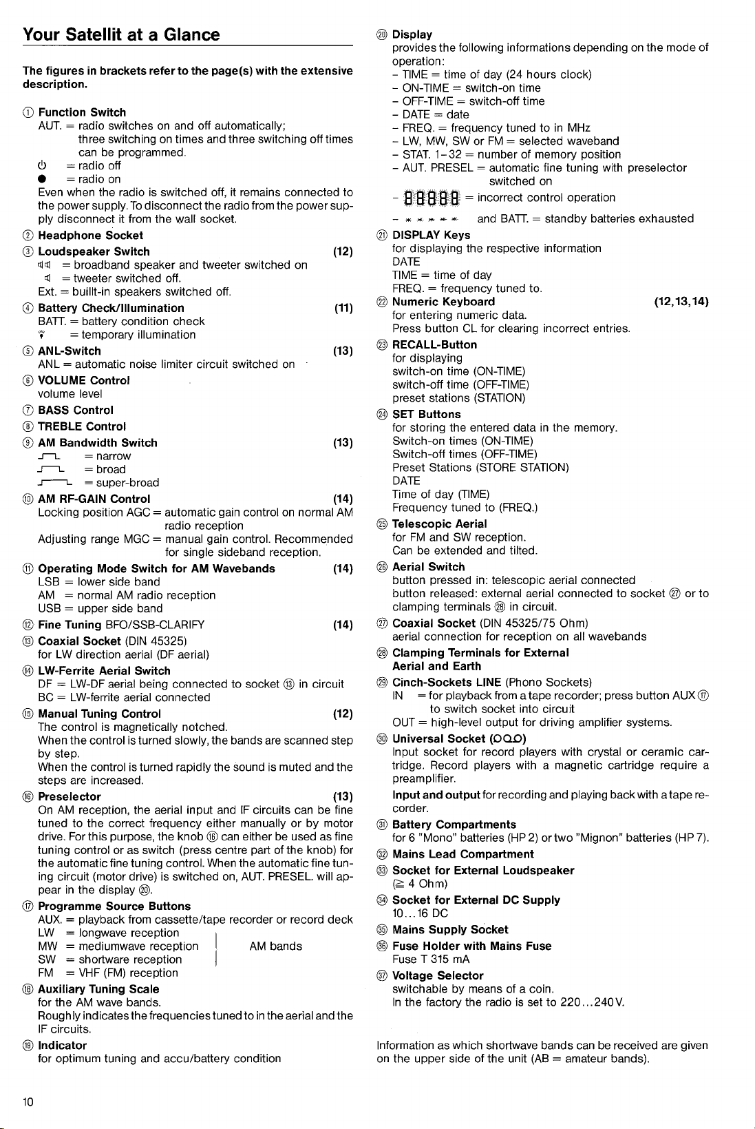
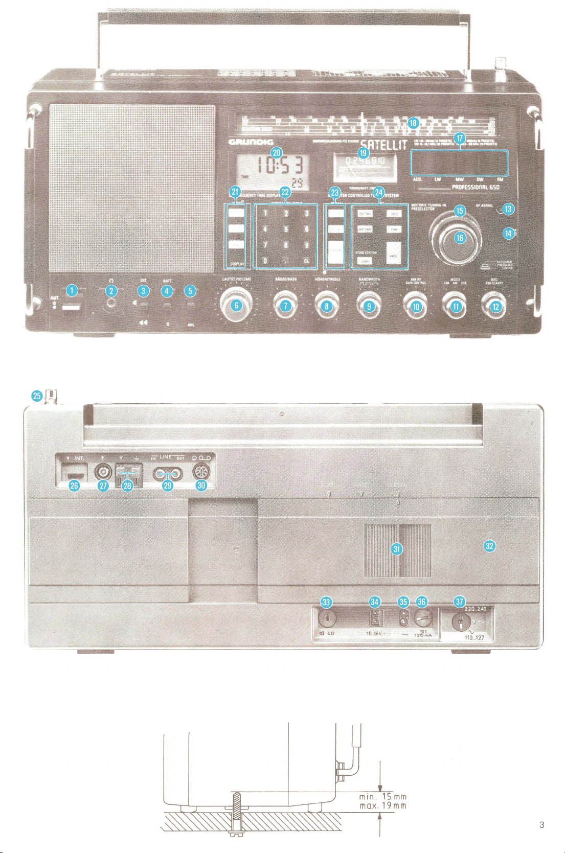
Your Satellit at a Glance
The figures
description.
G)
Function Switch
AUT.
<!>
•
Even when the radio is switched off, it remains connected to
the power supply.
ply disconnect
0 Headphone Socket
® Loudspeaker Switch (12)
~~
~
Ext. =
0 Battery Check/Illumination
BATI. = battery condition
·•·
® ANL-Switch (13)
ANL
® VOLUME Control
volume level
0 BASS Control
® TREBLE Control
®
AM
...r-t..
~
_,.----._ = super-broad
@AM
Locking position AGC = automatic gain control
Adjusting range MGC
® Operating Mode Switch for
LSB = lower side band
AM
USB = upper side band
@ Fine Tuning BFO/SSB-CLARIFY (14)
@ Coaxial Socket
for
LW-Ferrite Aerial Switch
@
DF
BC = LW-ferrite aerial connected
@)
Manual Tuning Control (12)
The control is magnetically notched.
When the control is turned slowly, the bands are scanned step
by
When the
steps are increased.
@ Preselector (13)
On
tuned
drive. For this purpose, the
tuning
the automatic fine tuning
ing circuit (motor drive) is switched on,
pear
® Programme Source Buttons
AUX.
LW = longwave reception
MW
SW = shortware reception
FM = VHF
@)
Auxiliary Tuning Scale
for the
Roughly indicates the frequencies tuned to
IF
®Indicator
for optimum tuning and accu/battery condition
in
brackets refer to the page(s) with the extensive
= radio switches on and off automatically;
three switching
can be programmed.
= radio off
=radio
=broadband
=tweeter
=automatic
Bandwidth Switch (13)
RF-GAIN Control (14)
= normal
LW
= LW-DF aerial being connected to socket @
step.
AM
in
= playback from cassette/tape recorder or record
= mediumwave reception
circuits.
on
buillt-in speakers switched off.
=temporary
to
control
switched off.
=narrow
= broad
AM
direction aerial
control is turned rapidly the sound is muted and the
reception, the aerial input and
the correct frequency either manually
or
the display
(FM)
AM
wave bands.
on
times and three switching off times
To
disconnect the radio from the power sup-
it
from the wall socket.
speaker and tweeter switched on
check
illumination
noise limiter circuit switched
radio reception
=manual
for
radio reception
(DIN
45325)
(DF
as switch (press centre part of the knob) for
gain control. Recommended
single sideband reception.
AM
Wavebands (14)
aerial)
IF
knob@
control. When the automatic fine tun-
can either be used as fine
AUT.
on
on
normal
in
circuit
circuits can be fine
or
by
motor
PRESEL. will ap-
@).
AM
bands
reception
in
the aerial and the
(11)
AM
deck
@)Display
provides the following informations depending
operation:
- TIME = time of day (24 hours clock)
-
ON-TIME=
-OFF-TIME=
-DATE=
-
FREQ.
LW,
-
-
STAT.
AUT.
-
-
s-.:atfa~a
- * "'
@ DISPLAY Keys
for displaying the respective information
DATE
TIME
= time of day
FREQ.
switch-on time
switch-off time
date
= frequency tuned to
MW,
SW
or
FM
1-32
PRESEL = automatic fine tuning with preselector
,..
,._
,.
= frequency tuned to.
= selected waveband
= number of memory position
switched on
= incorrect control operation
and BATI. = standby batteries exhausted
in
MHz
® Numeric Keyboard
for entering numeric data.
Press button
CL for clearing incorrect entries.
on
the mode
(12, 13, 14)
@ RECALL-Button
for displaying
switch-on time (ON-TIME)
switch-off time
preset stations
(OFF-TIME)
(STATION)
® SET Buttons
for storing the entered data
Switch-on times (ON-TIME)
Switch-off times
Preset Stations (STORE
DATE
Time of day
Frequency tuned to
(OFF-TIME)
(TIME)
(FREQ.)
@ Telescopic Aerial
for
FM
and SW reception.
Can be extended and tilted.
@ Aerial Switch
button pressed in: telescopic aerial connected
button released: external aerial connected to
clamping terminals @
® Coaxial Socket
@ Clamping Terminals for External
@ Cinch-Sockets LINE (Phono Sockets)
connection for reception on all wavebands
aerial
Aerial and Earth
IN
= for playback from a tape recorder; press button AUX ®
to switch socket into circuit
OUT=
high-level output for driving amplifier systems.
@ Universal Socket
Input socket for record players with crystal
tridge. Record
preamplifier.
Input and output for recording and playing back with a tape re-
corder.
(DIN
(OQD)
players with a magnetic cartridge require a
in
the
memory.
STATION)
in
circuit.
45325/75 Ohm)
socket®
or
ceramic car-
or
® Battery Compartments
for 6 "Mono" batteries
(HP
2)
or
two
"Mignon" batteries (HP
7).
® Mains Lead Compartment
@ Socket for External Loudspeaker
~
4 Ohm)
® Socket for External DC Supply
10
...
16
DC
@ Mains Supply Socket
@ Fuse Holder with Mains Fuse
Fuse T
315
mA
® Voltage Selector
switchable
In
the factory the radio is set to
Information as which shortwave bands can be received are given
on the
upper
side of the unit
by
means of a coin.
220
... 240
(AB
= amateur bands).
V.
of
to
10
 Loading...