

Page 1
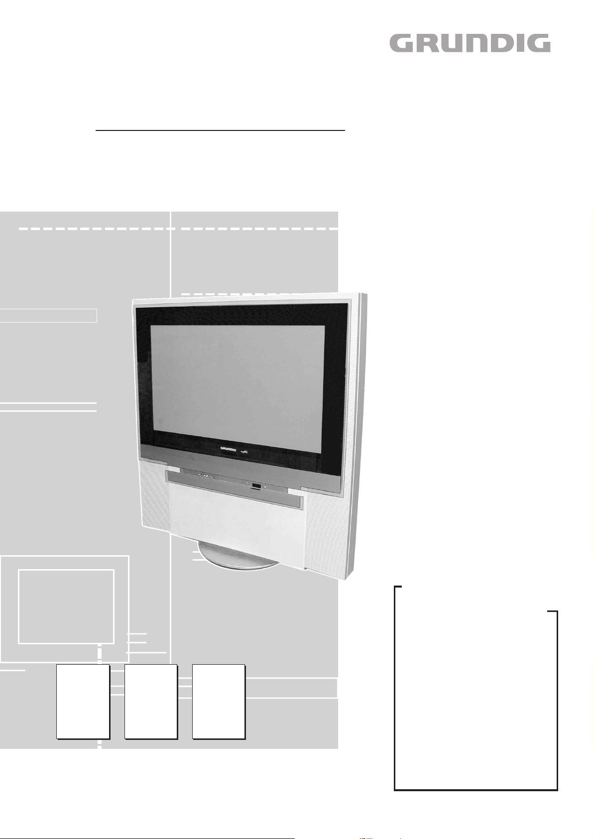
TV Service Manual
1. Ergänzung / Supplement 1
Fine Arts PlanaVision
PW 110-8110/9 Dolby
GCM2800 / VNM
Zusätzlich erforderliche Unterlagen für den Komplettservice
Additionally required Service Documents for the Complete Service
Service
Manual
Planatron
PW 110-520/9
PALplus
Materialnr./Part No.
720100246000
Materialnummer/Part Number 720100246100
Änderungen vorbehalten/Subject to alteration • Printed in Germany IP
H-S42 0402
http://www.grundig.de
Service
Manual
GDV Modul 1
Materialnr./Part No.
720100279000
720100279200
Service
Manual
Sicherheit
Safety
Materialnr./Part No.
720108000000
Grundig Service
Hotline Deutschland…
Technik:
TV
TV
SAT
VCR/LiveCam
HiFi/Audio
Car Audio
Telekommunikation
Planatron
Ersatzteil-Verkauf: Mo.-Fr. 8.00-19.00 Uhr
Kundendienst/Werkstätten:
gebührenpflichtig
(8.00-22.00 Uhr)
…Mo.-Fr. 8.00-18.00 Uhr
0180/52318-41
0180/52318-49
0180/52318-48
0180/52318-42
0180/52318-43
0180/52318-44
0180/52318-45
Fax:
Telefon: 0180/52318-40
Telefon:
Fax:
0180/52318-51
0180/52318-99
0180/52318-50Fax:
Mo.-Fr. 8.00-18.00 Uhr
0180/52318-52
0180/52318-46
Page 2

Allgemeiner Teil / General Section Fine Arts PlanaVision PW 110-8110/9 Dolby
Es gelten die Vorschriften und Sicherheitshinweise
gemäß dem Service Manual "Sicherheit", Materialnummer 720108000000, sowie zusätzlich die eventuell abweichenden, landesspezifischen Vorschriften!
Inhaltsverzeichnis
Seite
Allgemeiner Teil ................................. 1-2…1-42
Einführung.................................................................................... 1-2
Modulübersicht ............................................................................. 1-3
Technische Daten ........................................................................ 1-4
Servicehinweise ........................................................................... 1-5
Reinigung der Scheibe und des Displays .................................... 1-8
Software Update .......................................................................... 1-9
Bedienhinweise .......................................................................... 1-10
Platinenabbildungen
und Schaltpläne ................................. 2-1…2-50
Netzschalterplatte (Index 00) ....................................................... 2-1
Netzschalterplatte (Index 01) ....................................................... 2-5
Motorsteuerung – Drehfuß ........................................................... 2-9
Motorsteuerung – Bedienteilabdeckung .................................... 2-11
Buchsenplatte ............................................................................ 2-14
NF-Verstärker Subwoofer .......................................................... 2-16
Baustein-Signal Terrestrisch ...................................................... 2-19
Baustein-Signal Terrestrisch PIP mit Splitter ............................. 2-23
Adapter-RS-232-Platte ............................................................... 2-26
Chassis Digital ........................................................................... 2-27
– Teil 1 ...................................................................................... 2-33
– Teil 2 ...................................................................................... 2-37
– Teil 3 ...................................................................................... 2-41
– Teil 4 ...................................................................................... 2-45
– Teil 5 ...................................................................................... 2-47
The regulations and safety instructions shall be valid
as provided by the "Safety" Service Manual, part
number 720108000000, as well as the respective
national deviations.
Table of Contents
Page
General Section ................................. 1-2…1-42
Introduction .................................................................................. 1-2
Module List ................................................................................... 1-3
Technical Data ............................................................................. 1-4
Service Notes ............................................................................... 1-5
Cleaning the Screen and Display ................................................. 1-8
Software Update .......................................................................... 1-9
Operating Hints .......................................................................... 1-26
Layout of PCBs
and Circuit Diagrams ........................ 2-1…2-50
Mains Switch Panel (Index 00) .................................................... 2-1
Mains Switch Panel (Index 01) .................................................... 2-5
Motor Control – Turning Foot ....................................................... 2-9
Motor Control – Operating Panel Cover ..................................... 2-11
Socket Board ............................................................................. 2-14
AF Amplifier Subwoofer ............................................................. 2-16
Module Signal Terrestrial ........................................................... 2-19
Module Signal Terrestrial PIP with Splitter ................................. 2-23
Adapter RS232 Board ................................................................ 2-26
Chassis Digital ........................................................................... 2-27
– Part 1 ...................................................................................... 2-33
– Part 2 ...................................................................................... 2-37
– Part 3 ...................................................................................... 2-41
– Part 4 ...................................................................................... 2-45
– Part 5 ...................................................................................... 2-47
Explosionszeichungen und
Ersatzteillisten ...................................... 3-1…3-5
Allgemeiner Teil
Einführung
In dieser Service-Manual-Ergänzung ist das Gerät "Fine Arts
PlanaVision PW 110-8110/9 Dolby" der Serie Planatron dokumentiert.
Nähere Informationen entnehmen Sie bitte der Modulübersicht.
Hinweis: Für das DVD-Laufwerk "GDV Modul 1" sind die Ersatzteillisten dieser Ergänzung zu verwenden. Die technischen Informationen
(z.B. Servicehinweise, Platinenabbildungen, Schaltpläne, etc.) sind
den Service Manuals zum GDV Modul 1 (Materialnummern
720100279000, 720100279200) zu entnehmen.
Grundlage für den Service sind:
– Service Manual Planatron PW110-520/9 PALplus
(Materialnummer 720100246000)
– Service Manual GDV Modul 1
(Materialnummern 720100279000, 720100279200)
– Service Manual "Sicherheit" (Materialnummer 720108000000)
Exploded Views and
Spare Parts Lists ................................. 3-1…3-5
General Section
Introduction
This Service Manual supplement documents the "Fine Arts PlanaVision
PW 110-8110/9 Dolby" TV set of the Planatron family.
For more information please consult the Module List.
Note: For the DVD drive "GDV Module 1" use the spare parts lists of
this supplement. Technical information (e.g. service instructions, PCB
layouts, circuit diagrams, etc.) is to be found in the Service Manuals to
the GDV Module 1 (Part numbers 720100279000, 720100279200).
The basic documents for the service are:
– Service Manual Planatron PW110-520/9 PALplus
(Part no. 720100246000)
– Service Manual GDV Modul 1
(Part no. 720100279000, 720100279200)
– Service Manual "Safety" (Part no. 720108000000)
1 - 2 GRUNDIG Service
Page 3

Fine Arts PlanaVision PW 110-8110/9 Dolby Allgemeiner Teil / General Section
293053080300
•
–
293053080100
–
•
293053010200
–
•
293053020100
–
•
293053020300
–
•
293053070100
–
•
Chassis Digital 293053050600
•
–
Modulübersicht / Module List
Fernbedienung "Personal Remote 10"
Remote Control
Standby-Netzteil
Standby Mains Section
Netzschalterplatte
Mains Switch Board
Netzteil Box
Mains Section Box
NF Netzteil
AF Mains Section
Subwoofer Verstärker
Subwoofer Amplifier
Motorsteuerung Drehfuß
Motor control turnit foot
Motorsteuerung Bedienteilabdeckung
Motor Control Operating Panel Cover
Baustein Lüftersteuerung
Module Fan Control
NF Baustein
AF Module
Grundplatte Signal Feature
Basic Board Signal Feature
Baustein-Signal DW
Module Signal DW
Baustein-Signal Terrestrisch
Module Signal Terrestrial
Baustein-Signal Terrestrisch mit Splitter
Module Signal Terrestrial with Splitter
Buchsenplatte
Socket Board
Buchsenplatte Fuß
Socket Board Stand
Anschlussplatte Signal
Connecting Board Signal
Materialnummer
Part Number
296420611501
293053060300
293053112100
293053060100
293053060200
293253091100
293053080200
293053090100
293053030100
293053040400
293053040300
Fine Arts PlanaVision
PW 110-8110/9 Dolby
GCM2800
(VNM)
Ergänzung
Supplement
720100246100
•
–
•
–
–
•
•
–
–
•
–
Service Manual
Materialnr./ Part No
720100246000
–
•
–
•
•
–
–
•
•
–
•
Baustein Signal SAT
Module Signal SAT
Netzteil Display
Mains Section Display
Display 830074216102
DVD Kit 1
293053020200
293062099000
296322750100
nachrüstbar 2x SAT anstelle 2x terr.
–
–
•
(Mix zwischen Terr./SAT)
retrofitting 2x SAT instead of 2x terr.
(Mix between Terr./SAT)
•
–
•
–
GRUNDIG Service 1 - 3
Page 4

Allgemeiner Teil / General Section Fine Arts PlanaVision PW 110-8110/9 Dolby
Technische Daten / Technical Data
Fine Arts PlanaVision PW 110-8110/9 Dolby
Plasma Display Panel
Sichtbares Bild
Visible picture
Bildschirmdiagonale
Screen diagonal
Formatumschaltung
Format switching
Elektronik / Electronic
Programmspeicherplätze
Programme positions
TV-Guide ja / yes
Easy Dialog-System ja / yes
Tuner
TV-Normen
TV-Standards
Stereo Systeme
Stereo systems
Videotext
Teletext
Format Automatic, 14:9, 16:9, automatische Umschaltung auf PALplus (16:9)/
AV6 bei Nachrüstung Dockingstation / AV6 when retrofitted with Docking station
2 terr. PLL Frequenz Synthesizer Tuning, global Pinning mit/with double window
nachrüstbar 2 SAT anstelle 2 terr. (Mix zwischen terr./SAT-Tuner)
retrofitting 2 SAT instead of 2 terr. (Mix between terr./SAT-tuner)
4:3, Cinema Zoom, Panorama Zoom 2 steps
automatic switching to PALplus (16:9)
PAL, SECAM, NTSC 4.43MHz + 3.58MHz,
Nicam 5.85MHz (Skan, B, F, E) + 6.52MHz (GB)
Megatext Level 2.5, VPS
Megatext level 2.5, VPS
Flat 1
107cm
107cm (42")
199 + 5 AV
B/G, L/L', I, D/K/K'/D, M
German A2 (B/G/D/K)
Musikleistung
Music power
Anschlüsse Front / Connections Front
Kopfhörer
Headphones
Cinch-AV-Buchse
Cinch-AV-socket
S-Video (AV4)
Anschlüsse Rückwand / Connections Rear Panel
Euro AV 1 (schwarz/black)
Euro AV 2 DVD
Euro AV 3 (blau/blue)
Euro AV 5
Standard VGA / 2 Cinch NF/AF in
Interface
Lautsprecherbuchsen
Loudspeaker sockets
Cinch-NF-Buchse Ausgang
Cinch-AF socket output
Netzteil / Mains Stage
Netzspannung (Regelbereich)
Mains voltage (variable)
Netzfrequenz
Mains frequency
Leistungsaufnahme
Power consumption
Semi-standby
Standby
Stereo 3,5mm Klinkenbuchse, Lautstärke regelbar, individuelle Tonkanalwahl bei 2-Ton-Empfang
Stereo 3.5mm jacksocket, adjustable volume, individual channel selection with dual-sound broadcasts
FBAS Ein-/Ausgang, RGB Eingang, SBAS Ein-/Ausgang, Megalogic, Decoder, 16:9 / Pin8
CCVS in-/output, RGB input, SCVS in-/output, Megalogic, decoder capable, 16:9 / Pin8
FBAS Ein-/Ausgang, SBAS Ein-/Ausgang, Decoder, 16:9 / Pin8
CCVS in-/output, SCVS in-/output, decoder capable, 16:9 / Pin8
Bildschirmauflösung 640X480, 31,5kHz/60Hz, Textmode 31,5kHz/70Hz
Screen resolution 640X480, 31.5kHz/60Hz, Textmode 31.5kHz/70Hz
Westernbuchse 8-Pin für Software Service/Update
Western socket 8-pin for software service/update
3 x 2 Click Fit 4Ω für Front-Stereo-Boxen L+R, Center oder Subwoofer
3 x 2 click fit 4Ω for front stereo boxes L+R, center or subwoofer
6x, Audio Stereoausgang mit Regelung für L/R/Center und Surround-Signal für drahtlosen Dolby Kanal
6x, audio stereo output with variable level for L/R/center and surround signal for wireless Dolby channel
2 X 30W L+R
20W Center
40W Subwoofer
1 x FBAS Video / in
2 x Audio / in
4-polige Buchse Y-Chroma / in
4-pin socket Y-Chroma / in
165 … 265V AC
50 / 60Hz
ca. 400W
ca. 85W
< 7W
1 - 4 GRUNDIG Service
Page 5
Fine Arts PlanaVision PW 110-8110/9 Dolby Allgemeiner Teil / General Section
Servicehinweise
Leitungsverlegung
Bevor Sie die Leitungen und insbesondere die Masseleitungen lösen,
muss die Leitungsverlegung zu den einzelnen Baugruppen beachtet
werden (Fig. 6).
Nach erfolgter Reparatur ist es notwendig, die Leitungsführung wieder
in den werkseitigen Zustand zu versetzen um evtl. spätere Ausfälle
oder Störungen zu vermeiden.
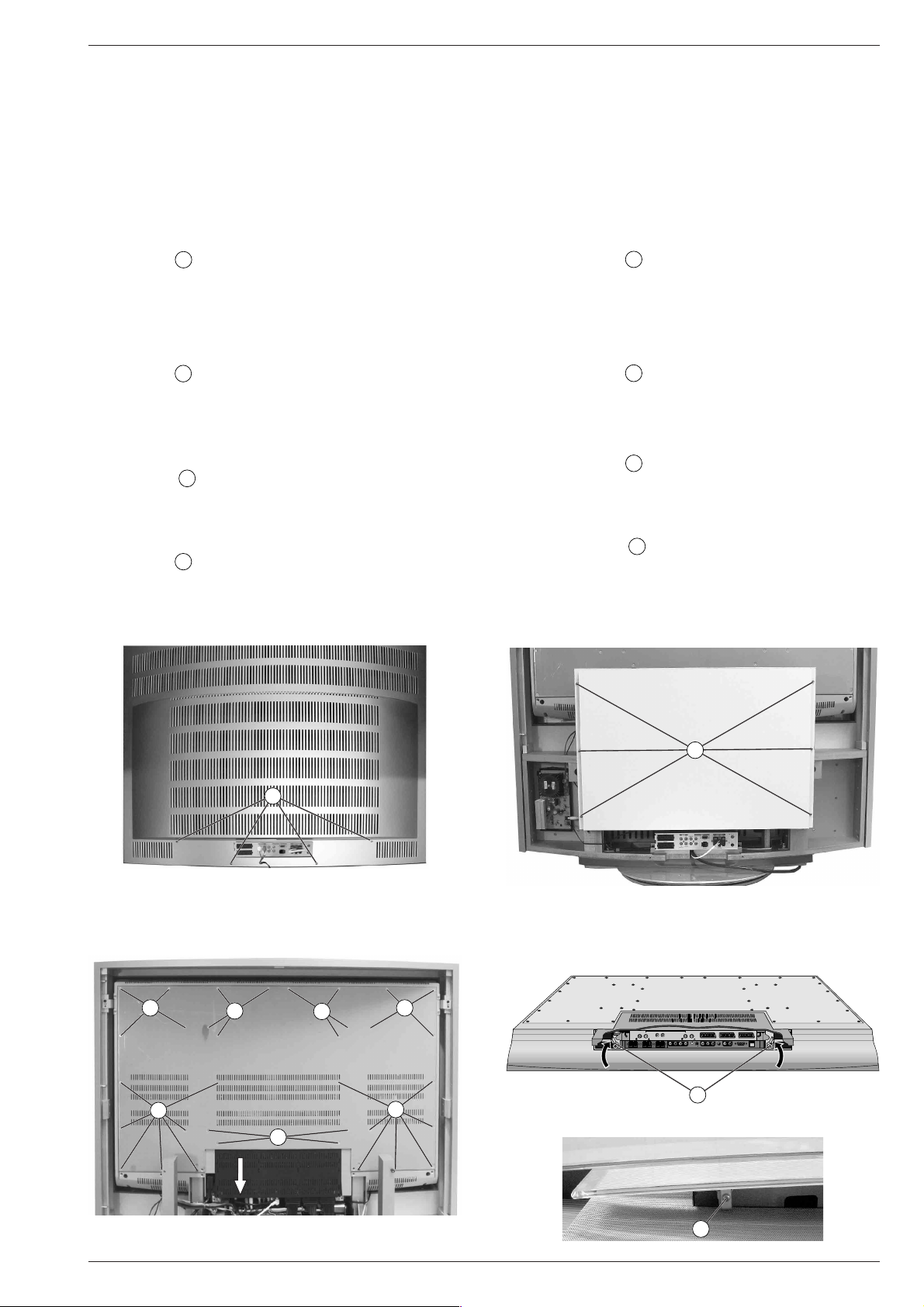
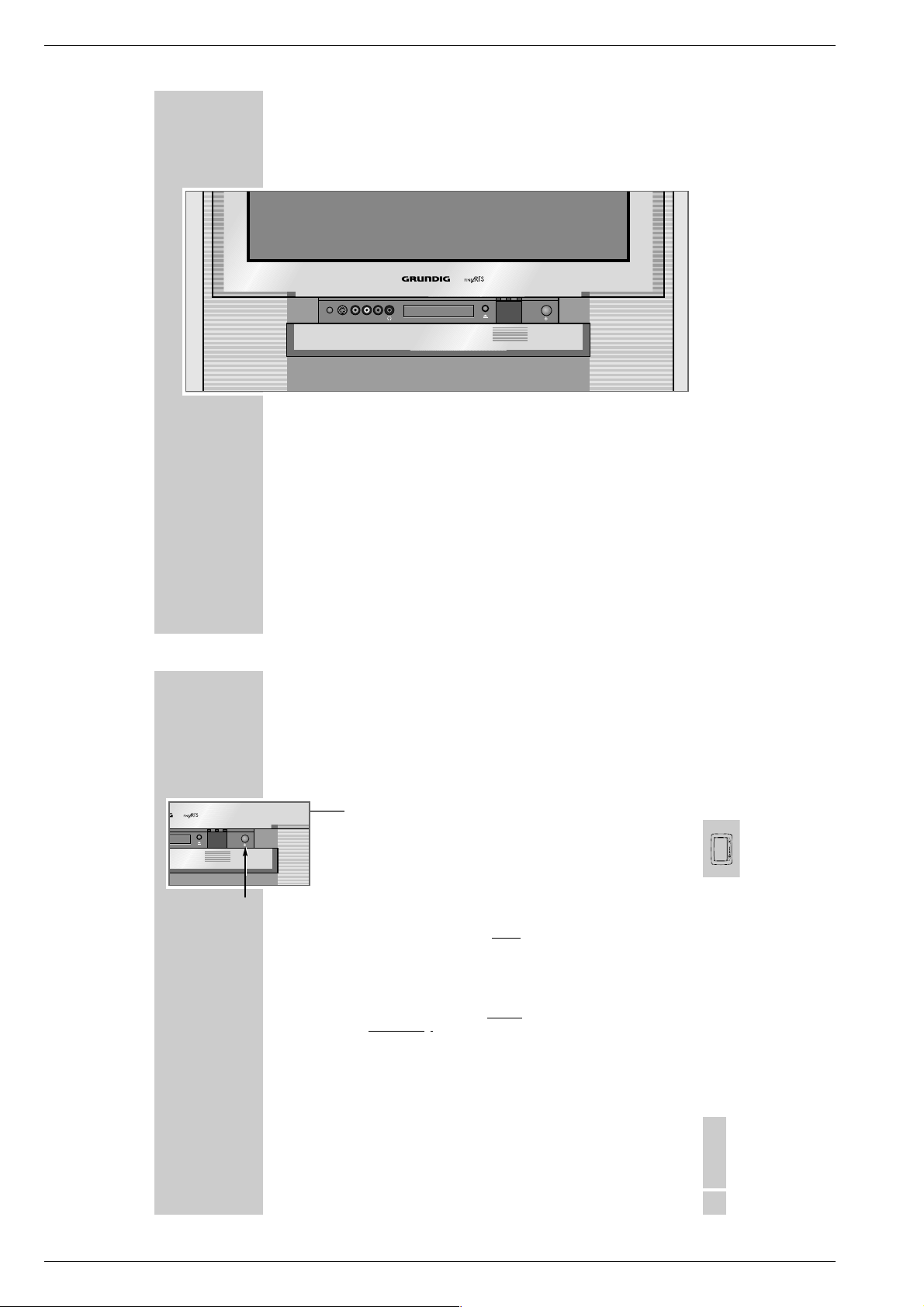
1. Geräterückwand abnehmen
– Netzstecker ziehen.
– Alle Kabel und Steckverbindungen an der Geräterückseite lösen.
– 4 Schrauben A (Fig. 1) herausschrauben.
– Rückwand nach unten schieben und abnehmen.
Achtung: Bei Geräten mit integriertem "WT 2"-Modul (Funkmodul
für kabellose Boxen) ist beim Abnehmen der Geräterückwand das Antennenkabel am "WT 2"-Modul zu lösen.
2. Subwoofer ausbauen
– Geräterückwand abnehmen (Punkt 1).
– 6 Schrauben B (Fig. 2) herausschrauben und Subwoofer abneh-
men.
– Gegebenenfalls Klemmverbindungen lösen.
Montagehinweis: Es darf kein Kabel am Subwoofer anliegen.
3. NF-Verstärker – Subwoofer ausbauen
– Geräterückwand abnehmen (Punkt 1).
– 2 Schrauben C (Fig. 6) herausschrauben und NF-Verstärker -
Subwoofer herausnehmen.
– Gegebenenfalls Klemm- und Steckverbindungen lösen.
4. DVD-Netzteil ausbauen
– Subwoofer ausbauen (Punkt 2).
– 2 Schrauben D (Fig. 6) herausschrauben und Halteblech abneh-
men.
– DVD-Netzteil nach oben herausziehen.
– Gegebenenfalls Steckverbindungen lösen.
Service Instructions
Wiring
Before disconnecting any leads and especially the earth connecting
leads observe the way they are routed to the individual assemblies
(Fig. 6).
On completion of the repairs the leads must be laid out as originally
fitted at the factory to avoid later failures or disturbances.
1. Remove Rear Panel
– Pull out the mains plug.
– Disengage all cables and connectors from the rear panel.
– Undo the 4 screws A (Fig. 1).
– Slide the rear panel down and remove it.
Attention: on TV sets with integrated "WT 2" module (radio module
for wireless loudspeakers) disengage the aerial cable on
the "WT 2" module before removing the rear panel.
2. Removing the Subwoofer
– Remove the rear panel (Point 1).
– Undo the 6 screws B (Fig. 2) and then remove the subwoofer.
– Disengage the clamping connectors if necessary.
Assembly hint: prevent the cables from touching the subwoofer.
3. Removing the AF Amplifier – Subwoofer
– Remove the rear panel (Point 1).
– Undo the 2 screws C (Fig. 6) and then remove the AF amplifier -
subwoofer.
– Disengage the clamping and plug-in connectors if necessary.
4. Removing the DVD Mains Unit
– Remove the subwoofer (Point 2).
– Undo the 2 screws D (Fig. 6) and then remove the sheet-metal
holder.
– Pull the DVD mains unit out to the top.
– Disengage the plug-in connectors if necessary.
A
E E
E
E
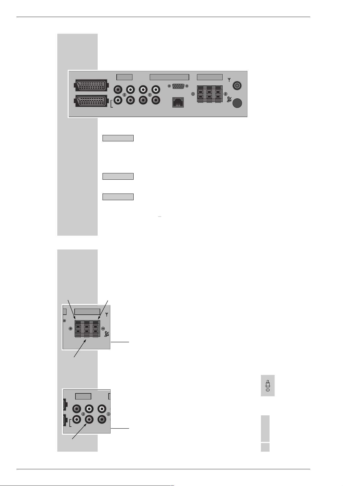
Anschlussbox
Connection Box
E
E
E
Fig. 2Fig. 1
Fig. 4
TERR. IN
TERR. SAT 2
Bedienteil von unten
Control Unit bottom View
B
IN TERR. OUT
LAUDIO OUTR
F
EURO AV 3 EURO AV 2 EURO AV 1 TERR. SAT 1
Fig. 3
GRUNDIG Service 1 - 5
Fig. 5
H
Page 6
Allgemeiner Teil / General Section Fine Arts PlanaVision PW 110-8110/9 Dolby
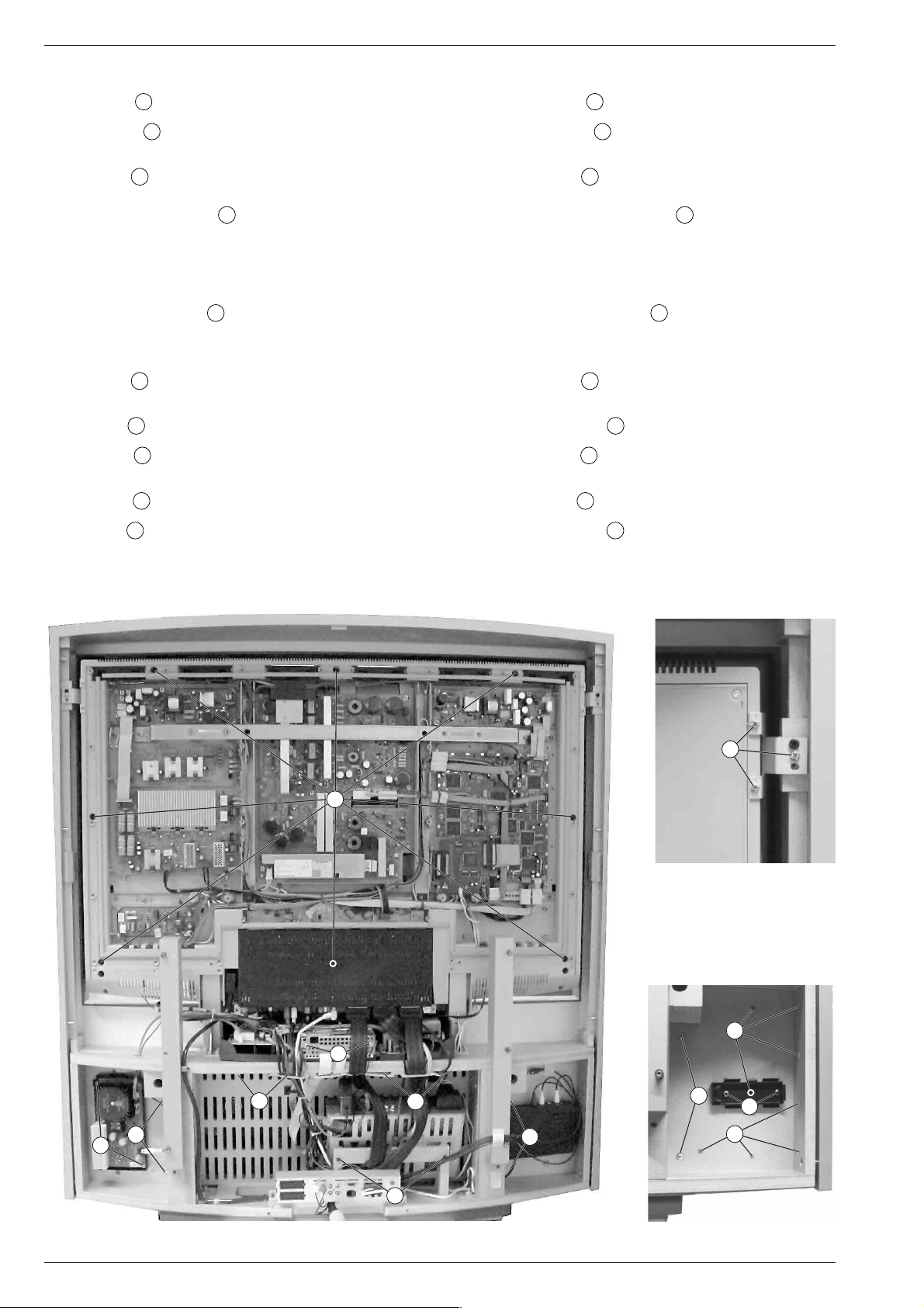
5. Scheibe abnehmen
– Subwoofer ausbauen (Punkt 2).
– 34 Schrauben E (Fig. 3) herausschrauben und Display-Rückwand
abnehmen.
F
– Verriegelungen
(Fig. 4) lösen, Anschlussbox (Fig. 3) nach unten
schieben und herausnehmen.
– Gegebenenfalls Steckverbindungen lösen.
– 8 Schrauben
G
(Fig. 6) herausschrauben.
– Scheibe vorsichtig nach vorne abnehmen.
Montagehinweis: Schrauben G (Fig. 6) nur handfest anziehen.
(Bruchgefahr der Scheibe!)
6. Bedienteilabdeckung ausbauen
– Gerät am Netz anschließen und Bedienteilabdeckung nach unten
gleiten lassen.
– Netzstecker ziehen.
– Linke und rechte Schraube H (Fig. 5) lösen und die Bedienteilab-
deckung nach oben abnehmen.
7. Display ausbauen
– Scheibe abnehmen (Punkt 5).
– 4 Schrauben K (Fig. 6 / 8) herausschrauben.
– Lautsprecherwand nach vorne abziehen und Lautsprecher-Steck-
verbindung lösen.
– 3 Schrauben I (Fig. 7) jeweils links / rechts oben herausschrauben
und Haltebleche abnehmen.
– 2 Schrauben C (Fig. 6) herausschrauben und NF-Verstärker –
Subwoofer herausnehmen.
– "WT 2"-Modul (optional) links anziehen und herausnehmen.
– 2 Schrauben J (Fig. 8, optional) herausschrauben und "WT 2"-
Halter herausnehmen.
– 8 Schrauben L (Fig. 8) jeweils links / rechts unten herausschrauben.
– Gehäuserahmen nach vorne neigen und abnehmen.
– Steckverbindungen lösen und Display nach oben abnehmen.
5. Removing the Glass Pane
– Remove the subwoofer (Point 2).
– Undo the 34 screws E (Fig. 3) and then remove the display's rear
panel.
F
– Disengage the locks
(Fig. 4), slide the connection box down
(Fig. 3) and then remove it.
– Disengage the plug-in connectors if necessary.
– Undo the 8 screws
G
(Fig. 6).
– Carefully remove the glass pane to the front.
Assembly hint: tighten the screws G (Fig. 6) only by hand (to
prevent the glass pane from breaking!)
6. Removing the Control Panel Cover
– Connect the TV set with the mains then let slide down the control
panel cover.
– Pull out the mains plug.
– Undo the left and right screws H (Fig. 5) and then remove the
control panel cover to the top.
7. Removing the Display
– Remove the glass pane (Point 5).
– Undo the 4 screws K (Fig. 6 / 8).
– Pull the loudspeaker panel out to the front and disengage the
loudspeaker plug connectors.
– Undo the 3 screws each I (Fig. 7) in the left / right top corners and
then remove the sheet-metal holders.
– Undo the 2 screws C (Fig. 6) and then remove the AF amplifier –
subwoofer.
– Pull at the left side of the "WT 2" module (optional) and remove it.
– Undo the 2 screws J (Fig. 8, optional) and then remove the "WT 2"
holder.
– Undo the 8 screws each L (Fig. 8) in the left / right bottom corners.
– Tilt the housing frame to the front and remove it.
– Disengage the plug-in connectors and remove the display to the top.
I
G
Fig. 7
L
Y
M
K
C
M
WT 2
K
D
K
J
L
Fig. 6
1 - 6 GRUNDIG Service
Fig. 8
Page 7
Fine Arts PlanaVision PW 110-8110/9 Dolby Allgemeiner Teil / General Section
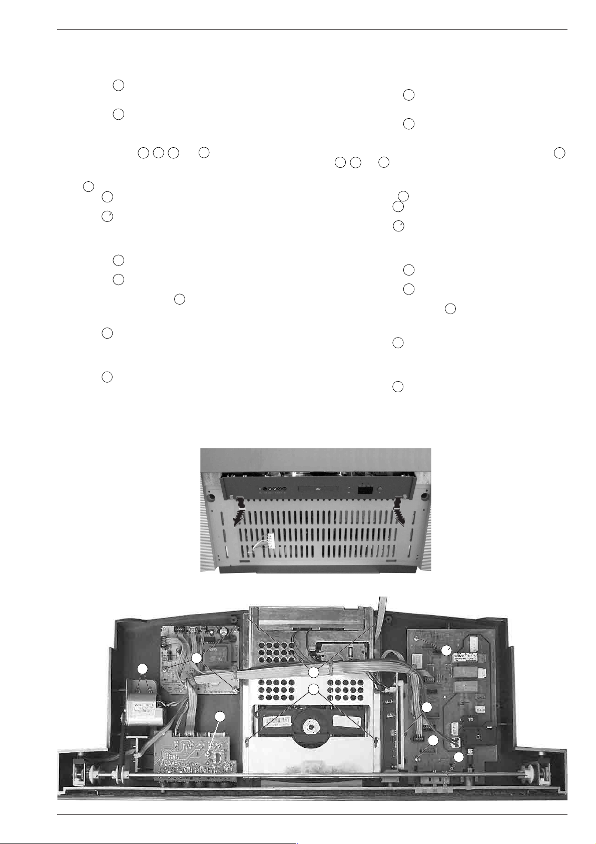
8. Bedienwanne ausbauen
– DVD-Netzteil ausbauen (Punkt 4).
– Bedienteilabdeckung ausbauen (Punkt 6).
– "WT 2"-Modul (optional) links anziehen und herausnehmen (Fig. 6).
– 4 Schrauben K (Fig. 6 / 8) herausschrauben.
– Lautsprecherwand nach vorne abziehen und Lautsprecher-Steck-
verbindung lösen.
– 4 Schrauben M (Fig. 6) herausschrauben.
– Bedienwanne nach unten kippen und vorne herausziehen (Fig. 9).
Hinweis: Zum Ausbau der einzelnen Bausteine der Bedienwanne
genügt es, die Bedienwanne vorne so weit herauszuziehen, dass die
vorderen Schrauben N, O, P bzw. S (Fig. 10) zugänglich sind.
– Gegebenenfalls Steckverbindungen lösen.
8.1 Netzschalterplatte ausbauen
– LED T (Fig. 10) ablöten bzw. Steckverbindung lösen.
– Schraube N (Fig. 10) herausschrauben.
– Bedienwanne nach hinten schieben.
– Schraube N (Fig. 10) von Geräterückseite aus herausschrauben.
– Netzschalterplatte herausnehmen.
– Gegebenenfalls Steckverbindungen lösen.
8.2 DVD-Laufwerk ausbauen
– 2 Schrauben P (Fig. 10) herausschrauben.
– Bedienwanne nach hinten schieben.
– 2 Schrauben Q (Fig. 10) herausschrauben.
– DVD-Laufwerk herausnehmen.
– Gegebenenfalls 2 Schrauben Y (Fig. 6) herausschrauben, Ab-
deckblech abnehmen und Steckverbindungen lösen.
8.3 Eject-Platte ausbauen
– Schraube O (Fig. 10) herausschrauben.
– Eject-Platte herausnehmen.
– Gegebenenfalls Steckverbindungen lösen.
8.4 Buchsenplatte ausbauen
– Schraube S (Fig.10) herausschrauben.
– Buchsenplatte herausnehmen.
– Gegebenenfalls Steckverbindungen lösen.
8. Removing the Control Tray
– Remove the DVD mains unit (Point 4).
– Remove the control panel cover (Point 6).
– Pull at the left side of the "WT 2" module (optional) and remove it
(Fig. 6).
– Undo the 4 screws K (Fig. 6 / 8).
– Pull the loudspeaker panel out to the front and disengage the
loudspeaker plug connectors.
– Undo the 4 screws M (Fig. 6).
– Tilt the control tray down and pull it out to the front (Fig. 9).
Note: to remove the individual components of the control tray it will
suffice to pull the control tray out to the front until the front screws N,
O
, P and S (Fig. 10) become accessible.
– Disengage the plug-in connectors if necessary.
8.1 Removing the Mains Switch Board
– Unsolder the LED T (Fig. 10) or disengage the plug-in connectors.
– Undo the screw N (Fig. 10).
– Push the control tray back.
– Undo the screw N (Fig. 10). Accessible from rear side.
– Remove the mains switch board.
– Disengage the plug-in connectors if necessary.
8.2 Removing the DVD Drive
– Undo the 2 screws P (Fig. 10).
– Slide back the control tray.
– Undo the 2 screws Q (Fig. 10).
– Remove the DVD drive.
– If necessary, undo the 2 screws Y (Fig. 6), remove the sheet-metal
cover and disengage the plug-in connectors.
8.3 Removing the Eject Board
– Undo the screw O (Fig. 10).
– Remove the Eject board.
– Disengage the plug-in connectors if necessary.
8.4 Removing the Socket Board
– Undo the screw S (Fig.10).
– Remove the socket board.
– Disengage the plug-in connectors if necessary.
Fig. 10
Fig. 9
U
R
Q
P
S
N
O
N
T
GRUNDIG Service 1 - 7
Page 8
Allgemeiner Teil / General Section Fine Arts PlanaVision PW 110-8110/9 Dolby
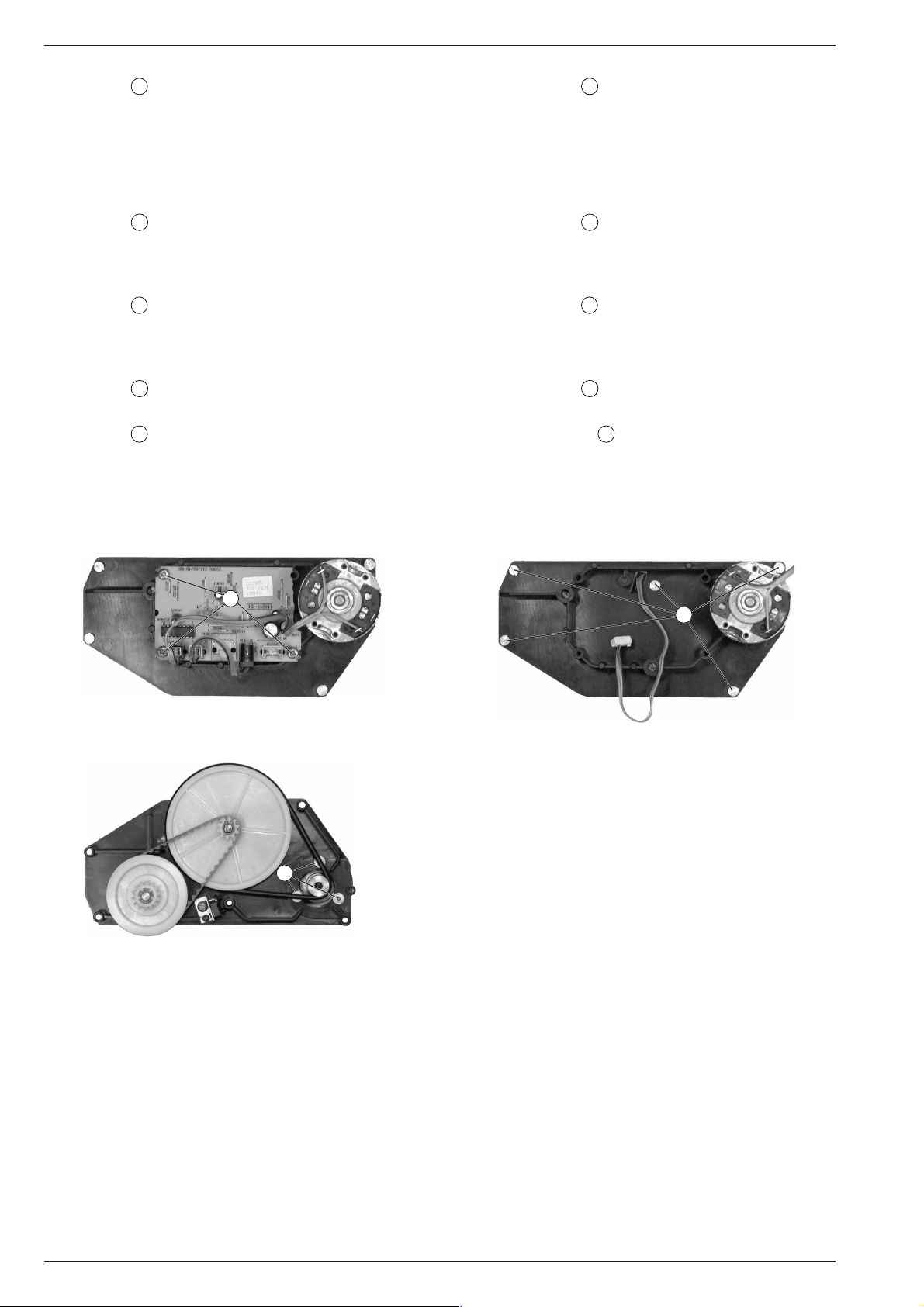
8.5 Blenden-Motor ausbauen
– 2 Schrauben U (Fig. 10) herausschrauben.
– Blenden-Motor anheben und Antriebsriemen abnehmen.
– Blenden-Motor herausnehmen.
– Gegebenenfalls Steckverbindungen lösen.
Montagehinweis: Die Spannung des Antriebsriemen so wählen,
dass der Riemen in der Mitte um 90° zu drehen ist.
9. Motorsteuerung – Bedienteilabdeckung ausbauen
– Subwoofer ausbauen (Punkt 2).
– 3 Schrauben R (Fig. 10) herausschrauben.
– Motorsteuerung – Bedienteilabdeckung herausnehmen.
– Gegebenenfalls Steckverbindungen lösen.
10. Motorsteuerung – Drehmotor ausbauen
– Subwoofer ausbauen (Punkt 2).
– 3 Schrauben V (Fig. 11) herausschrauben.
– Motorsteuerung – Drehmotor herausnehmen.
– Gegebenenfalls Steckverbindungen lösen.
11. Drehmotor ausbauen
– Motorsteuerung – Drehmotor ausbauen (Punkt 10).
– 5 Schrauben W (Fig. 12) herausschrauben.
– Drehmotor mit Antriebsmechanik herausnehmen.
– Antriebsriemen abnehmen.
– 3 Schrauben X (Fig. 13) herausschrauben.
– Drehmotor herausnehmen.
8.5 Removing the Trimplate Motor
– Undo the 2 screws U (Fig. 10).
– Lift the trimplate motor and remove the drive belt.
– Remove the trimplate motor.
– Disengage the plug-in connectors if necessary.
Assembly hint: choose a drive belt tension which allows the belt
to be turned by 90° at its centre position.
9. Removing the Motor Control – Control Panel Cover
– Remove the subwoofer (Point 2).
– Undo the 3 screws R (Fig. 10) .
– Remove the motor control – control panel cover.
– Disengage the plug-in connectors if necessary.
10. Removing the Motor Control – Rotary Motor
– Remove the subwoofer (Point 2).
– Undo the 3 screws V (Fig. 11).
– Remove the motor control – rotary motor.
– Disengage the plug-in connectors if necessary.
11. Removing the Rotary Motor
– Remove the motor control – rotary motor (Point 10).
– Undo the 5 screws W (Fig. 12).
– Remove the rotary motor together with the drive mechanism.
– Remove the drive belt.
– Remove the 3 screws X (Fig. 13).
– Disengage the plug-in connectors if necessary.
V
Fig. 11 Fig. 12
X
Fig. 13
Reinigung der Scheibe und des Displays
– Scheibe abnehmen (Servicehinweise, Punkt 5).
– Nur mit beiliegendem Mikrofaser-Putztuch die Scheibe und das
Display reinigen.
Cleaning the Glass Pane and the Display
– Remove the glass pane (Service Instructions, Point 5).
– Clean the pane and the display only with the microfiber cleaning
cloth enclosed.
W
1 - 8 GRUNDIG Service
Page 9
Fine Arts PlanaVision PW 110-8110/9 Dolby Allgemeiner Teil / General Section
Software-Update
Das Aktualisieren der Geräte-Software inklusive Software-Download
ist in der zum Lieferumfang gehörenden Beschreibung (CD) der
"SERVICE Toolbox GSI" enthalten.
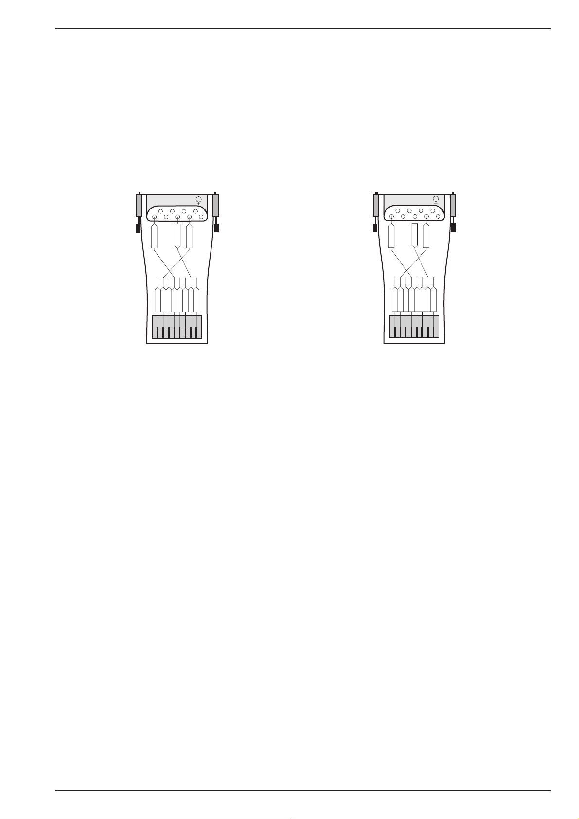
Benötigtes Equipment:
– SERVICE Toolbox GSI, Materialnummer 772004001200
– Kabel, Materialnummer 720089200000
– Adapter Western zu RS232, Materialnummer 720089210000.
Dieser ist entsprechend der folgenden Abbildung zusammenzubau-
en. Nicht benötigte Kabelenden sind gegenseitig zu isolieren.
Computer COM 1...4
9
8
7
6
1
2345
TxD
RxD
GND
rot
blau
orange
schwarz
weiß
grün
gelb
braun
Software Update
Updating of the software of the TV set including the software download
is contained in the description (CD) of the "SERVICE Toolbox GSI"
supplied.
Required equipment:
– SERVICE Toolbox GSI, Part number 772004001200
– Cable, Part number 720089200000
– Western-to-RS232 adapter, Part number 720089210000
This is to be assembled according to the Figure below. Not used
cable ends must be isolated against each other.
Computer COM 1...4
9
8
7
6
1
2345
TxD
RxD
GND
red
blue
orange
white
green
black
yellow
brown
Gewährleistung
Wir weisen ausdrücklich darauf hin, dass nur von GRUNDIG freigegebene System-Software zulässig ist. Wurde als Fehlerursache festgestellt, dass eine aus nicht legitimierten Quellen gleich welcher Herkunft
stammende oder eine veränderte System-Software in die Geräte
geladen wurde, so ist dies ein Fremdeingriff. Ein Fremdeingriff führt
zum Erlöschen jeglicher Gewährleistungsansprüche. GRUNDIG muss
daher alle aus diesen Gründen resultierenden Kostenerstattungen
generell ablehnen. Instandsetzungskosten, auch innerhalb der Gewährleistungszeit, gehen in diesen Fällen zu Lasten des Händlers bzw. des
Endkunden.
Warranty / Costs
We expressly point out that only operating software authorized by
GRUNDIG is allowed. If a failure is caused by an operating software
which has been downloaded from not authorized sources, independent of its origin, or a modified software, this represents an outside
interference. An outside interference leads to the expiration of any
warranty claims. For this reason, GRUNDIG is obliged to generally
refuse any payment due to such infringements. In such cases, the
repair costs are at the charge of the retailer or the final customer, even
within the period of warranty.
GRUNDIG Service 1 - 9
Page 10
Allgemeiner Teil / General Section Fine Arts PlanaVision PW 110-8110/9 Dolby
Bedienhinweise Dieses Kapitel enthält Auszüge aus der Bedienungsanleitung. Weitergehende Informationen entnehmen Sie bitte der
Bedienungsanleitung, deren Materialnummer Sie in der Ersatzteilliste finden.
VORBEREITEN
Aufstellen und Sicherheit
Beachten Sie die Hinweise im Abschnitt ‘Fernsehbetrieb’.
Montage
Montieren des Center-Lautsprecherpanels
1
Stecker des Lautsprecherpanels in die Buchse an der Vorderseite stecken.
2
Lautsprecherpanel aufstecken und mit den beiliegenden Schrauben von hinten befestigen.
___________________________________________________________________
2
VORBEREITEN
___________________________________________________________________
Montieren der Rückwand
1
Rückwand aufstecken und nach oben schieben.
2
Rückwand mit den Halteschrauben befestigen.
EURO AV 1
VGATVDOLBY
LOUDSPEAKER
TERR. IN
++L+
R
AUDIO OUT
VGA/AUDIO IN
LR
LL
VGA IN
SAT 1
RR
––L–
SURROUND
R
EURO AV 3
CENTERSW-SERVICE
DEUTSCH
3
1 - 10 GRUNDIG Service
Page 11
Fine Arts PlanaVision PW 110-8110/9 Dolby Allgemeiner Teil / General Section
S
-V
H
S
V
i
d
e
o
i
n
S
lide
r
A
u
L
VORBEREITEN
____________________________________________________________________________
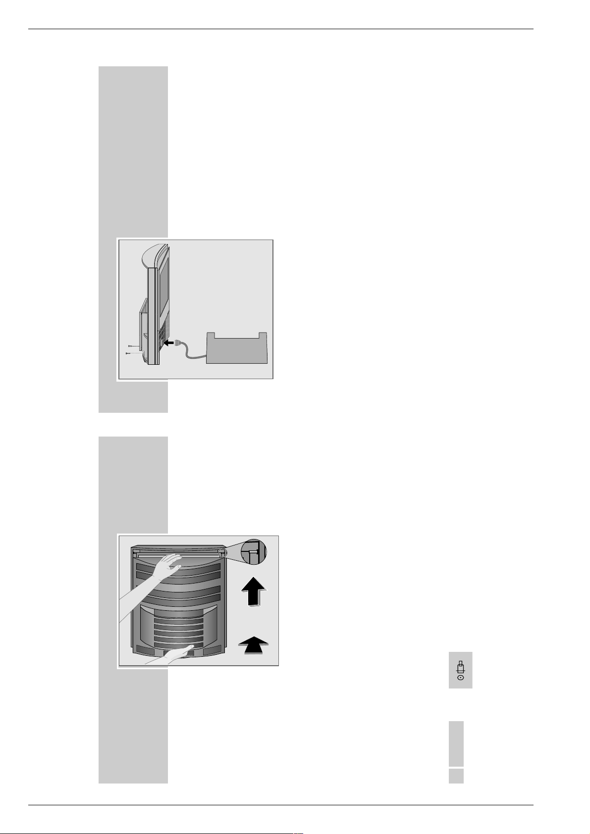
Bedienteilabdeckung montieren
1
Fernsehgerät an das Netz anschließen.
2
Halteteile der Bedienteilabdeckung nach unten gleiten lassen, dazu mit der
Hand annähern (a) und Halteteil mit dem Finger nach unten drücken (b).
3
Taste »Slider« drücken.
4
Bedienteilabdeckung in die Halteteile des Fernsehgerätes einführen.
5
Taste »Slider « drücken und warten, bis die Bedienteilabdeckung nach oben
fährt.
6
Netzstecker ziehen, Bedienteilabdeckung bündig zur Glasscheibe ausrichten
und festschrauben.
7
Netzstecker wieder in die Steckdose stecken.
a
b
S
l
i
d
e
r
S
-
V
H
S
V
i
d
e
o
in
L
A
u
d
i
o
in
R
Hinweis:
Das Typenschild befindet sich an
der Unterseite der Rückwand.
4
VORBEREITEN
____________________________________________________________________________
Batterien in die Fernbedienung einlegen
1
Batteriefach öffnen, dazu Deckel abziehen.
2
Batterien einlegen (Typ Micro, z.B. R03P, 3 x1,5 V).
Dabei Polung beachten.
Hinweis:
Wenn das Fernsehgerät auf die Fernbedienbefehle nicht mehr richtig reagiert, können die Batterien verbraucht sein. Verbrauchte Batterien unbedingt
entfernen. Für Schäden, die durch ausgelaufene Batterien entstehen, kann
nicht gehaftet werden.
Umwelthinweis:
Die Batterien – auch schwermetallfreie – dürfen nicht im Hausmüll entsorgt
werden. Verbrauchte Batterien müssen in die Altbatteriesammelgefäße bei
Handel und öffentlich-rechtlichen Entsorgungsträgern gegeben werden.
Fernbedienung für zusätzliche Geräte vorbereiten
Zum Betrieb des DVD-Players und eines Grundig Videorecorders muß in die
Fernbedienung eine Codezahl eingegeben werden.
Gerät DVD-Player* Videorecorder Werkseinstellung (Reset)
Codezahl 424 238 859
Werkseitig bereits eingegeben
*
1
»Mode « drücken und gedrückt halten.
2
Mit »1...0« Codezahl eingeben.
– Die Fernbedienung ist jetzt für die Bedienung des zusätzlichen Gerätes
vorbereitet.
GRUNDIG Service 1 - 11
DEUTSCH
5
Page 12
Allgemeiner Teil / General Section Fine Arts PlanaVision PW 110-8110/9 Dolby
LOUDSPEAKER
R
++L+
R
––L–
CENTERE
T
DOLBY
AUDIO OUT
SURROUND
VG
R
L
LR
DVD
DIGITAL OUT
ANSCHLIESSEN
________________________________________________________________
Die Anschlüsse
EURO AV 1
EURO AV 3
DVD
DIGITAL OUT
LR
SURROUND
AUDIO OUT
VGA/AUDIO IN
VGADOLBY
LL
VGA IN
RR
EURO AV1, AV3 Euro/AV-Buchsen (die Buchse »Euro-AV2« ist intern durch den einge-
bauten DVD-Player belegt).
DOLBY
R L Ausgangsbuchsen für aktive-Front-Boxen.
SURROUND Ausgangsbuchsen für aktive Surround-Boxen.
AUDIO OUT R L Ausgangsbuchsen für HiFi-Anlage.
DVD DIGITAL OUT Digitaler Tonausgang (DVD-Player)
VGA
VGA IN Anschluß für Computer.
VGA AUDIO IN Ton-Anschluß für Computer.
LOUDSPEAKER
R+ R-, L+ L- Klemmbuchsen für externe Front-Lautsprecher.
Center Klemmbuchsen für externe Center-Lautsprecher
SW-SERVICE Service-Buchse
É
TERR. IN Antennenbuchse
ʐ
6
SAT 1 Antennenbuchse des Sat-Tuners (nachrüstbar).
LOUDSPEAKER
++L+
R
––L–
R
CENTERSW-SERVICE
TERR. IN
SAT 1
ANSCHLIESSEN
__________________________________________________________________________
Lautsprecher anschließen
Der Planavision ist mit Front-, Centerlautsprecher und Subwoofer ausgestattet.
Rechts
Links
Center
Surround
Anstelle der eingebauten Front und Centerlautsprecher können auch passive
Lautsprecher an den Klemmbuchsen, oder aktive Lautsprecher an den Cinchbuchsen angeschlossen werden.
Für den Dolby Surround ProLogic-Betrieb müssen aktive Surround-Lautsprecher
an der Cinch-Buchse angeschlossen werden. Anstelle aktiver Surround-Lautsprecher kann auch das als Zubehör erhältliche Wireless Surround System WST 864
oder WT 2 zur drahtlosen Übertragung des Surround Kanals angeschlossen
werden.
1
Front Lautsprecher an den Klemmbuchsen »R+ R-«, »L+ L-« (passiv) bzw
an den Cinchbuchsen »DOLBY L« bzw. »DOLBY R« (aktiv) anschließen.
Anstelle des eingebauten Center-Lautsprechers kann auch ein externer Center-Lautsprecher an den Klemmbuchsen angeschlossen werden. Dazu muß
das Kabel des eingebauten Center-Lautsprechers aus der Klemmbuchse
»CENTER« gelöst werden. Achtung! ein externer Center-Lautsprecher darf
nicht parallel mit dem eingebauten Center-Lautsprecher betrieben werden.
Hinweise:
Zum Einstecken des Lautsprecherkabels drücken Sie die Klemmhebel nieder.
Die »–« Ader des Lautsprecherkabels stecken Sie in die schwarze (–) Klemme. Die »+« Ader (markierte oder farbige Ader) des Lautsprecherkabels
stecken Sie in die rote Klemme.
Anstelle Aktiver Lautsprecher kann auch jeweils ein eigener Endverstärker
mit passiven Lautsprechern angeschlossen werden.
2
Aktive Surround-Lautsprecher an die Cinchbuchse »DOLBY SURROUND«
anschließen.
DEUTSCH
7
1 - 12 GRUNDIG Service
Page 13
Fine Arts PlanaVision PW 110-8110/9 Dolby Allgemeiner Teil / General Section
LOUDSPEAKER
R
++L+
R
– –L–
CENTERSW-SERVICE
VGA IN
VGADOLBY
EURO AV 1
EURO AV 3
TERR. IN
SAT 1
AUDIO OUT
SURROUND
VGA/AUDIO IN
RR
LL
LR
DVD
DIGITAL OUT
ANSCHLIESSEN
__________________________________________________________________________
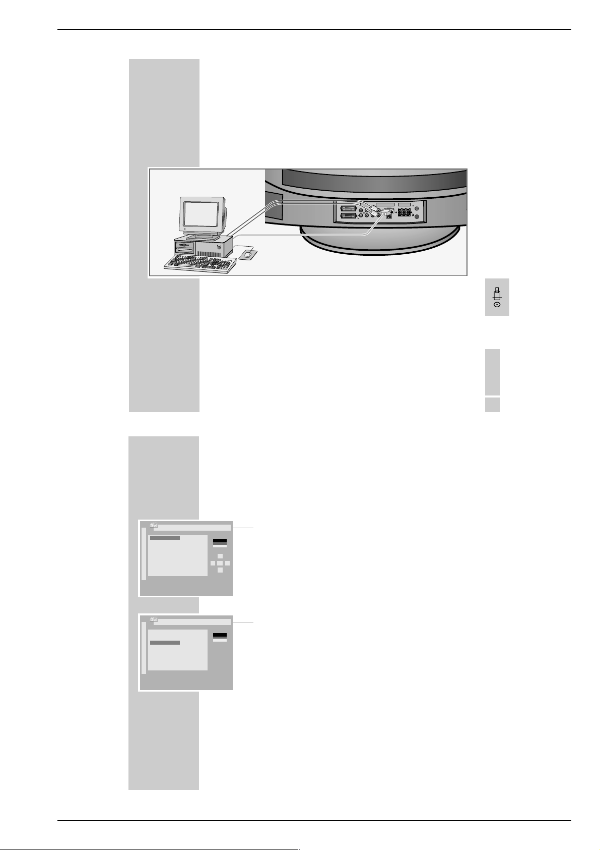
Computer (VGA) anschließen
Sie können den Planavision als PC-Monitor verwenden.
Das Fernsehgerät kann sich auf folgende Eingangsignale einstellen:
640 x 480 Pixel, 60 Hz/31,5 kHz
640 x 400 Pixel, 70 Hz/31,5 kHz
640 x 350 Pixel, 70 Hz/31,5 kHz
1
VGA-Quelle (z.B. Computer, Spiele-Konsole) mit einem handelsüblichen
VGA-Kabel an Buchse »VGA« anschließen.
2
Tonausgang des Computers (wenn vorhanden) mit einem handelsüblichen
Cinch-Kabel an die Buchsen »L AUDIO IN R« anschließen.
Hinweise:
Am PC muss eine der obengenannten Auflösungen eingestellt sein (siehe
Systemsteuerung des PC´s).
Das Display eines angeschlossenen Laptops muß ausgeschaltet werden (über
Tastatur oder Systemsteuerung des Laptops, siehe dazu Bedienungsanleitung
des Laptops).
Beim Anschluß eines Laptops muß dieser erst angeschlossen und dann eingeschaltet werden.
DEUTSCH
9
P+
Dialogsprache einstellen
ļ
–
Deutsch âe‰tina
Dansk Magyar
Espanol Polski
Francais Türkçe
English
Italiano
Norge
Nederlands
Portugues
Svenska
Suomi
Ļ
Mit dieser Taste auswählen und mit
P-
OK bestätigen
OK
Bestätigen
■
P+
Gerätestandort einstellen
ļ
Österreich Portugal
Belgien Schweden
Schweiz Finnland
Deutschland Tschechien
–
Dänemark Slowakei
Spanien Slowenien
Frankreich Ungarn
Großbritannien Polen
Italien Türkei
Norwegen übrige
Niederlande
Ļ
Gerätestandort
P-
Befindet sich Ihr Land nicht in der
Auswahl, wählen Sie “übrige“ Länder.
OK
Bestätigen
■
Ǻ
●
EINSTELLUNGEN
Fernseh-Programme einstellen
Der Planavision ist mit dem automatischen Programmsuchlauf ATS euro plus
ausgestattet, der Ihnen die Programmplatzbelegung abnimmt.
1
Nach dem Einschalten des Fernsehgerätes Dialogsprache »Deutsch« mit
»OK« bestätigen.
Zurück
P+
ļ
OK
Łĵ
Ļ
P-
TXT
TV
●
TXT
TV
●
Hinweis:
Wenn die Seite »Dialogsprache wählen« nicht erscheint, Seite mit »
anschließend »OK« aufrufen. Das Dialogcenter blendet sich ein.
Mit » P+« oder »P-« die Zeile »Automatische Programmierung« anwählen
und mit »OK« bestätigen.
Mit » P+« oder »P-« die Zeile »Komplette Neuprogrammierung« anwählen
und mit »OK« bestätigen
2
Gerätestandort mit »OK« bestätigen.
– Der automatische Programmsuchlauf startet. Der Vorgang kann je nach
– Nach Beenden der automatischen Programmplatzbelegung erscheint eine
3
Hinweistafel mit »TXT« abschalten.
– Die Tafel »Installation« erscheint.
_____________________________________________________________
i
« und
Anzahl der zu empfangenden Fernseh-Programme eine Minute und länger
dauern.
Tafel mit Hinweisen zum Installationsmenü.
10
GRUNDIG Service 1 - 13
Page 14
Allgemeiner Teil / General Section Fine Arts PlanaVision PW 110-8110/9 Dolby
Personal Remote 10
P+
INSTALLATION
ļ
Lautsprecher-Konfiguration
Dolby-Einpegelung
–
Audio-/Video-Anschlüsse
VGA-Anschluß
Zeit und Datum
TV-GUIDE-Konfiguration
Ļ
P-
OK
Aufrufen
■
Ǻ
Zurück
●
EINSTELLUNGEN
TXT
Hilfe
?
●
TV
●
________________________________________________________________________
Dolby-Pegel einstellen
Hinweis:
Wenn Sie den Planavision nicht mit der Standard-Lautsprecherausstattung
(Links/rechts, Center) betreiben, wählen Sie vor der »Dolby-Einpegelung«
den Punkt »Lautsprecher Konfiguration« und stellen ein, welche Lautsprecher
Sie angeschlossen haben.
1
Mit »P+« oder »P-« die Zeile »Dolby-Einpegelung« wählen und mit »OK«
bestätigen.
2
Alle Lautsprecher gleichlaut zueinander einstellen.
3
Einstellung mit »TXT« beenden.
– Eine Tafel mit Hinweisen zum Easy Dialog System erscheint.
4
Mit »TXT« zum Fernsehbetrieb schalten.
Hinweis:
Alle Punkte der Tafel »INSTALLATION« können auch zu einem späteren Zeitpunkt im Easy Dialogcenter unter Punkt »INSTALLATION« aufgerufen werden.
TV
AUF EINEN BLICK
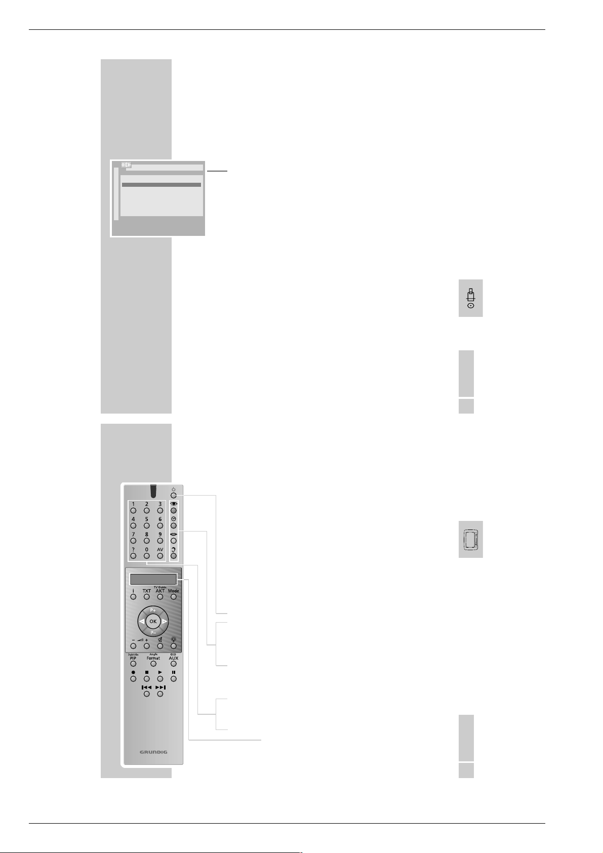
Die Fernbedienung
Mit der Fernbedienung Personal Remote 10 können Sie zusätzlich zum
Planavision auch einen Grundig Videorecorder und den DVD-Player bedienen.
Für den Betrieb eines Videorecorder muß die Fernbedienung von Ihrem
Fachhändler vorbereitet werden.
Die Bedienung von Videorecorder und DVD-Player entnehmen Sie bitte der
gesonderten Bedienungsanleitung des entsprechenden Gerätes.
Bedienen des Fernsehgerätes
Zum Bedienen des Fernsehgerätes muß »TV« in der Anzeige der
Fernbedienung stehen. Gegegebenenfalls Taste »Mode « so oft drücken, bis
»TV« in der Anzeige steht.
Ǽ
z
Ȅ
M Keine Funktion bei Fernsehbetrieb.
F
1…0 Programmwahl und Einschalten des Planavisions aus Stand-by,
AV Eingabe der Videotext-Seitennummern, AV Stellung wählen.
D
Schaltet den Planavision ab (Stand-by).
Bildeinstellungen, Menü »BILD-EINSTELLUNGEN« aufrufen.
Uhrzeit ein/aus.
Toneinstellungen, Menü »TON-EINSTELLUNGEN« aufrufen.
Durch aufeinanderfolgendes Drücken der Taste kann zwischen
den Toneinstellungen »Stereo«, »Dolby Pro Logic« und »Dolby
Surround« gewählt werden.
Kurzanleitung aufrufen.
Anzeige
DEUTSCH
11
__________________________________________________________
DEUTSCH
9
1 - 14 GRUNDIG Service
Page 15
Fine Arts PlanaVision PW 110-8110/9 Dolby Allgemeiner Teil / General Section
Personal Remote 10
10
TV
AUF EINEN BLICK
i
TXT Videotext-Betrieb, TV-Betrieb.
TV Guide
AKT TV-Guide, Info über aktuelle Sendung.
Mode Schaltet die Fernbedienung um, zur Bedienung von DVD-
P+ P– Schaltet den Planavision aus Bereitschaft ein ,
ǸǷ
OK Ändern und Aktivieren verschiedener Funktionen.
}
+ Lautstärke.
–
ĭ
R
Subtitle
PIP Im Videotext-Betrieb – Double Window (Fernsehbild und
Angle
Format Bildformat-Umschaltung.
OSD
AUX Vorwahltaste für verschiedene Funktionen.
II Standbild
______________________________________________________________________
Dialogcenter aufrufen (mit »i« und »OK«).
Player, Videorecorder.
Programmfortschaltung, Cursor nach oben/unten.
Cursor nach links/rechts.
Planavision nach links/rechts drehen
Ton ein/aus (stummschalten).
Anzeigen-Beleuchtung ein/aus. Die Beleuchtung wird nach
kurzer Zeit automatisch abgeschaltet.
Videotext auf den Bildschirmhälften);
im Fernseh-Betrieb – Kleinbild im Bild.
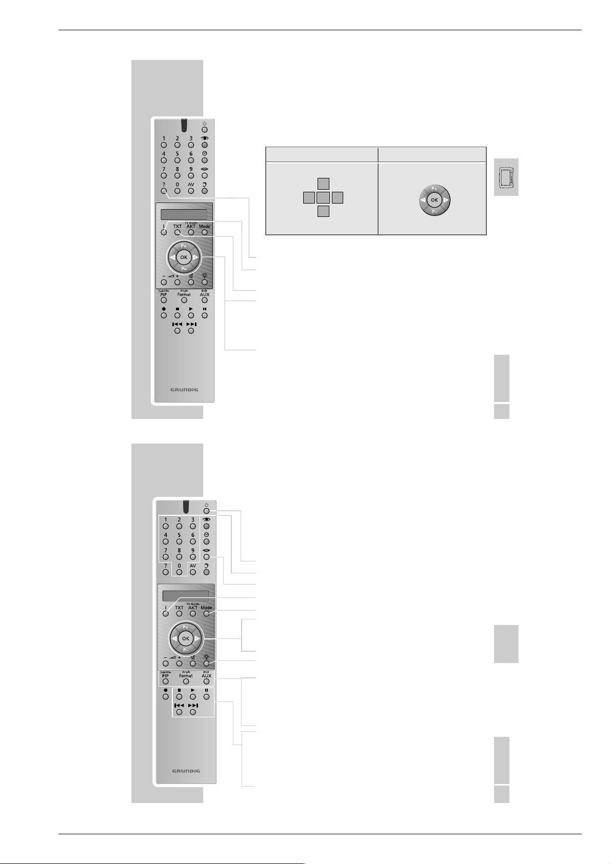
AUF EINEN BLICK
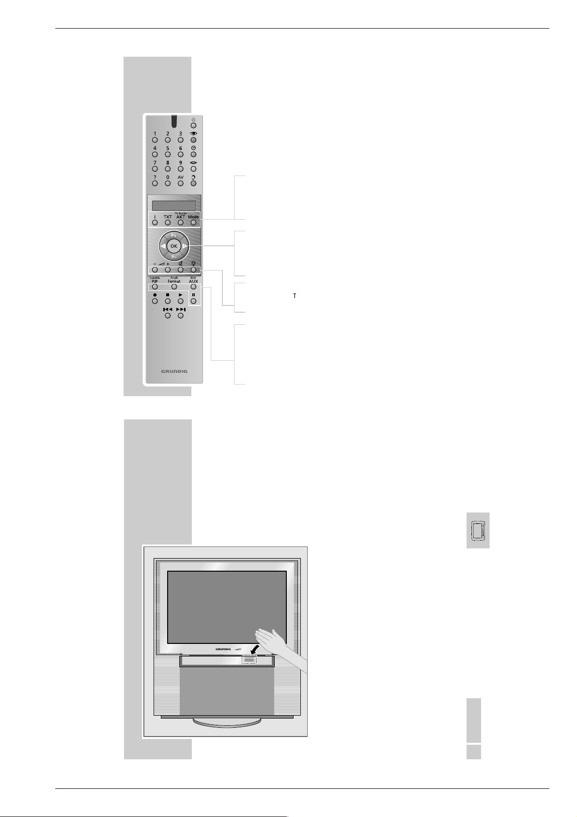
Die Vorderseite des Planavision
Automatisches Öffnen der Bedienteilabdeckung
Slider
Video in
Audio inLR
S-VHS
______________________________________________________________________
Bei Annäherung mit der Hand gleitet die Bedienteilabdeckung automatisch
nach unten und gibt die Bedienelemente frei.
Nach einigen Sekunden fährt die Glasscheibe automatisch wieder nach
oben.
Hinweis:
Ist an den Buchsen an der Vorderseite des
Planavision ein Camera-/Videorecorder oder
Kopfhörer angeschlossen, fährt die
Bedienteilabdeckung nicht automatisch nach
oben.
DEUTSCH
13
GRUNDIG Service 1 - 15
Page 16
Allgemeiner Teil / General Section Fine Arts PlanaVision PW 110-8110/9 Dolby
AUF EINEN BLICK
Bedienelemente
Slider
Video in
Audio inLR
S-VHS
Slider Schaltet das automatische Schließen der
S-VHS S-VHS Bildsignaleingang für Camerarecorder.
Video in Bildsignaleingang für Camerarecorder.
L Audio in R Tonsignaleingang für Camerarecorder.
y
ə
Ǽ
______________________________________________________________________
Bedienteilabdeckung aus/ein.
Kopfhöreranschluß.
Öffnet/schließt die Schublade der DVD-Players
Schaltet den Planavision ein/aus.
14
BETRIEB
IO
__________________________________________________________________________________
Planavision ein-/ausschalten
Planavision einschalten
1
Am Planavision »IO« drücken.
Die Anzeige leuchtet rot und wechselt nach einigen Sekunden in gelb.
Während die Anzeige gelb leuchtet, führt der Planavision eine interne
Systemabfrage durch. Diese dauert einige Sekunden, danach wechselt die
Anzeige in grün und das Fernsehbild erscheint am Bildschirm.
Planavision in Bereitschaft (Stand-by) schalten
1
An der Fernbedienung »Ǽ« einmal drücken. Der Planavision dreht sich in
die Mittelstellung und schaltet anschließend in Stand-by.
Planavision vollständig ausschalten
1
Am Planavision »IO« drücken, oder
Ǽ
« an der Fernbedienung zweimal drücken
»
oraussetzung:
V
Ökö-Netzschalter ist aktiviert (Dialogcenter, Menü »Sonderfunktionen«).
Hinweise:
Der Öko-Netzschalter wird nicht ausgelöst, wenn ein Timer programmiert ist,
oder der Kopierbetrieb eingeschaltet ist.
Wiedereinschalten ist nur mit »IO« am Planavision möglich.
An der Vorderseite zeigt eine Leuchtanzeige durch verschiedene Farben den
jeweiligen Betriebszustand an.
Grün = Betrieb.
Gelb = TV-GUIDE-Betrieb (ca 1/2 Std. nach dem Ausschalten, um die
Rot = Stand-by (Energiesparbetrieb, Timer programmiert).
Programmdaten zu laden), Copy-Betrieb.
DEUTSCH
15
1 - 16 GRUNDIG Service
Page 17
Fine Arts PlanaVision PW 110-8110/9 Dolby Allgemeiner Teil / General Section
Personal Remote 10
DIE BENUTZERFÜHRUNG
Bedienen des Easy Dialog Systems
Die Cursortasten der Fernbedienung werden wie untenstehend abgebildet am
Bildschirm dargestellt.
Tastendarstellung am Bildschirm Tasten an der Fernbedienung
P+
ļ
OK
Łĵ
Ļ
P-
D
i
TXT Zurück zum Fernsehbild.
P+ P– Bewegen des Balkens nach oben/unten;
ǸǷ
OK Aufrufen oder bestätigen der gewählten Funktion.
Kurzanleitung aufrufen.
Dialogcenter aufrufen (mit »i« und »OK«),
schaltet eine Tafel zurück.
bei zweiseitigen Menüs wird auf die zweite Seite
„umgeblättert”.
Einstellen von Werten.
________________________________________________________
DVD
Personal Remote 10
AUF EINEN BLICK
Die Fernbedienung
Mit der Fernbedienung „Personal Remote 10“ Ihres Fernsehgerätes bedienen
Sie auch Ihren DVD-Player.
Zum Bedienen des DVD-Players die Taste »Mode« so oft drücken, bis »
in der Anzeige steht.
9
1 … 0 Ziffern-Tasten für verschiedene Eingaben.
M
i
Mode Schaltet die Fernbedienung auf Bedienebene DVD.
P+ P– Wählen in den Menüs verschiedene Funktionen.
ǸǷ
OK Bestätigt Eingaben in den Menüs.
R
Subtitle
Angle
OSD
AUX Blendet die Menüzeile ein und wieder aus.
7
8
II Standbild bei DVD und Video-CD; Pause bei Audio-CD.
5as6
Schaltet das Fernsehgerät ab (Stand-by).
Zum Anwählen der Synchronsprache der DVD.
Ruft das Titelmenü der DVD/Video-CD auf.
Wählen in den Menüs verschiedene Funktionen.
Schaltet die Anzeigen-Beleuchtung ein/aus. Die Beleuchtung
wird nach kurzer Zeit automatisch abgeschaltet.
PIP Blendet während der Wiedergabe die Untertitel der DVD ein.
Format Wählt während der Wiedergabe verschiedene Blickwinkel
(Kamera-Standorte) von bestimmten Szenen oder Passagen
der DVD.
Beendet alle Funktionen, schaltet den DVD-Player auf „STOP“.
Startet die Wiedergabe;
aktiviert durch zweimaliges Drücken die Funktion „Resume“.
Schaltet während der Wiedergabe auf Bildsuchlauf vorwärts
oder rückwärts in verschiedene Geschwindigkeiten.
17
______________________________________________________
DVD
«
3
DEUTSCH
/
DEUTSCH
GRUNDIG Service 1 - 17
Page 18

Allgemeiner Teil / General Section Fine Arts PlanaVision PW 110-8110/9 Dolby
DIE BENUTZERFÜHRUNG
Mit der Benutzerführung können Sie alle Funktionen anwählen sowie die
notwendigen Einstellungen durchführen.
Symbole, Tasten und Dialogzeilen zeigen die möglichen Bedienschritte.
__________________________________
Die Menüzeile
1
Menüzeile mit »
– Die Abbildungen zeigen Ihnen die Möglichkeiten der Menüzeile.
<
Ö P K ( I R k
/
_
sa
off
S
sa
A
1 2 1 offnooff
S
»Ö« = Menüpunkt »Einstellungen«:
P
»
K
»
»(« = zum Anwählen der Tonspur.
»I« = zum Anwählen der Sprache von Untertiteln.
»R« = zum Anwählen verschiedener Blickwinkel.
»k« = zum Anwählen der Zoomfunktion.
2
Die Fortsetzung der Menüzeile mit »Ƿ« anwählen.
Z
;
st
_
»
Z
»
;
»
N
»
L
»
4
OSD
AUX« aufrufen.
>
« = zum Anwählen von Titeln.
« = zum Anwählen von Kapiteln.
N
« = zum Programmieren von Szenen.
« = zum Anwählen der Klangart.
« = zum Anwählen verschiedener Zeitlupen-Geschwindigkeiten.
« = zum Anwählen verschiedener Bildsuchlauf-Geschwindigkeiten.
« = zum minutengenauen Anwählen eines Abschnittes.
L
DIE BENUTZERFÜHRUNG
________________________________________________________
Der Menüpunkt »Einstellungen«
Ö P K ( I R k
/
O
>
A
S
8
1 2 1 offnooff
Bildformat
Schwarzwert
Bildverschiebung
16:9
Aus
■■◊■■■■■■■
U
Ü
»O« = »Bildmenü« mit den Funktionen
»>« = »Tonmenü« mit den Funktionen
»U« = »Sprachmenü« mit den Funktionen
Ü
« = Menü »Sonderfunktionen« mit den Funktionen
»
– Bildformat,
– Schwarzwert,
– Bildverschiebung.
– Digitalausgang,
– Analogausgang,
– Nachtmodus,
– Karaoke-Gesang.
– Audio (Dialoge),
– Untertitel,
– Menü.
– Zugriffskontrolle,
– Statusfenster,
– Öko-Standby (ohne Funktion).
>
/
DEUTSCH
5
1 - 18 GRUNDIG Service
Page 19
Fine Arts PlanaVision PW 110-8110/9 Dolby Allgemeiner Teil / General Section
DIE BENUTZERFÜHRUNG
________________________________________________________
Die Statusanzeige
In der Statusanzeige werden Informationen über die eingelegte DVD/Video-
.
!
DVD pause
2 : 04 : 26
0 : 00 : 21
CD, die Gesamtspielzeit und die abgelaufene Spielzeit der DVD/Video-CD
eingeblendet. Zusätzlich sehen Sie die jeweilige Funktion.
»2 : 05 :30« = Gesamtspielzeit.
»0 : 15 :00« = Abgelaufene Spielzeit.
.
« DVD = DVD eingelegt.
»
.
« VCD = Video-CD eingelegt.
»
,
« reading = DVD wird gelesen.
»
»{« no disc = keine DVD oder Video-CD eingelegt.
»]« opened = Schublade geöffnet.
»[« closing = Schublade geschlossen.
!
« error = Störungsmeldung.
»
ǵ
play« = Wiedergabe.
»
8
stop« = Wiedergabe beenden.
»
7
»II pause« = Wiedergabe-Pause.
»
x 4 x 8 x 32« = Bildsuchlauf vorwärts/rückwärts.
EW
» 1/4 1/8 1/2 1« = Zeitlupe vorwärts/rückwärts.
Die Dialoganzeige
In der Dialogzeile sehen Sie Informationen über den Betriebszustand.
Ö P
/
a
1
6
» « = Funktion nicht möglich.
x
locked
» « = Kindersicherung aktiviert.
G
safe
» « = Kindersicherung abgeschaltet.
H
2/2
» « = Blickwinkel für Szenen.
R
resume
» « = Wiedergabe wird fortgesetzt.
%
DIE BENUTZERFÜHRUNG
ÖPK(IRk
sa
A
S
/ 121offno off
Ö
PK(IRk
/ 121offno off
Audio (Dialoge)
O
Untertitel
>
Menü
A
8
U
S
Ü
Ö
PK(IRk
/ 121offno off
Audio (Dialoge)
O
A
Untertitel
S
>
Menü
a
U
Ü
Deutsch
Deutsch
Deutsch
Deutsch
Deutsch
Deutsch
________________________________________________________
Die Bedienung mit der Benutzerführung
Entnehmen Sie dem folgenden Beispiel den Aufbau der Benutzerführung und
die Anwahl der verschiedenen Menüs und Einstellungen.
OSD
Die Menüzeile wählen Sie mit der Taste »
te wählen Sie mit den Tasten »P –« oder »P +«, »
Der aktive Menüpunkt ist blau hervorgehoben. Menüpunkte, die mit der jeweiligen DVD keine Funktion haben sind grau markiert und können nicht angewählt
werden.
Die Fortsetzung der Menüzeile wählen Sie mit »
1
>
>
Menüzeile mit »
– Die Menüzeile wird eingeblendet.
2
Gewünschten Menüpunkt (im Beispiel »Ö«) mit »Ǹ« oder »Ƿ« wählen
und mit »P – « aktivieren.
OSD
AUX« aufrufen.
– Das Menü wird eingeblendet.
3
Menü (im Beispiel »U«) mit »P –« oder » P +« wählen und mit »Ƿ«
aktivieren.
– Das Sprachmenü wird eingeblendet.
4
>
Funktion (im Beispiel »Untertitel«) mit »P –« oder »P +« wählen und mit
« aktivieren.
»
Ƿ
5
Gewünschte Einstellung mit »P – « oder »P +« wählen.
Hinweis:
Mit »OK« kann schrittweise zurückgeschaltet werden zu den vorherigen
Menüs und Menüpunkten.
6
Menüzeile mit »
OSD
AUX« abschalten.
– Die eingestellten Funktionen oder Werte werden automatisch gespeichert.
AUX«, die einzelnen Menüpunk-
« oder »Ƿ«.
Ǹ
«.
Ƿ
/
DEUTSCH
7
GRUNDIG Service 1 - 19
Page 20
Allgemeiner Teil / General Section Fine Arts PlanaVision PW 110-8110/9 Dolby
KINDERSICHERUNG
Ö
PK(IRk
/ 121offno off
s
S
Zugriffskontrolle
O
Statusfenster
>
Öko-Standby
U
a
Ü
Ö
PK(IRk
/ 121offno off
O
Zugriffskontrolle
Statusfenster
>
Standby
U
Ü
26
Kode eingeben...
Ein
Ein
a
Kode eingeben
________________________________________________
Mit der Kindersicherung können Sie:
– Die Benutzung des DVD-Players ausschließen;
– bestimmte DVDs oder Video-CDs für die Wiedergabe freigeben oder sperren;
– Szenen von DVDs oder Video-CDs, die nicht für Kinder geeignet sind
sperren oder alternative Szenen auswählen.
Kindersicherung des DVD-Players aktivieren und
abschalten
Kindersicherung des DVD-Players aktivieren
1
( ) ( ) ( ) ( )
>
Menüzeile mit »
2
Menüpunkt »Ö« (Einstellungen) mit »Ǹ« oder »Ƿ« anwählen und mit
»P – « aktivieren.
3
Zeile »Ü« (Sonderfunktionen) mit »P – « auswählen und mit »Ƿ«
aktivieren.
4
>
Zeile »Zugriffskontrolle« mit » P –« oder »P +« anwählen und mit »Ƿ«
aktivieren.
5
Vierstellige Geheimnummer mit »1...0 « eingeben.
Hinweis:
Wenn die Geheimnummer das erste Mal eingegeben wird, wechselt die
Anzeige in »Kode bestätigen«.
Vierstellige Geheimnummer mit »1...0 « nocheinmal eingeben.
6
Zeile »Kindersicherung« mit »P –« oder »P +« anwählen und mit »Ƿ«
aktivieren.
OSD
AUX« aufrufen.
KINDERSICHERUNG
Ö
PK(IRk
/ 121offno off
O
Zugriffskontrolle
Statusfenster
>
Öko-Standby
U
Ü
Ö
PK(IRk
/ 121offno off
Zugriffskontrolle
O
Statusfenster
>
Öko-Standby
U
Ü
Ö
PK(IRk
/ 121offno off
O
Zugriffskontrolle
Statusfenster
>
Öko-Standby
U
Ü
Kindersicherung
Sicherungsstufe
Land ändern
Kode ändern
Kindersicherung
Sicherungsstufe
Land ändern
Kode ändern
Kindersicherung
Sicherungsstufe
Land ändern
Kode ändern
A
S
7
>
D
a
S
F
Das Symbol »D« mit »P – « oder »P +« anwählen.
8
Einstellung mit »
– Der DVD-Player ist verriegelt.
Hinweis:
Wird jetzt eine DVD oder Video-CD in die Schublade gelegt, erscheint die
Meldung »locked« (gesperrt) und Sie müssen die vierstellige Geheimnummer
eingeben.
Kindersicherung des DVD-Players abschalten
1
>
D
a
A
F
Zum Abschalten der Kindersicherung die Punkte 1 bis 8 im Kapitel „Kindersicherung des DVD-Players aktivieren“ wiederholen und das Symbol »F«
mit »P – « oder »P +« anwählen.
– Die Kindersicherung ist abgeschaltet.
Hinweis:
Falls Sie die Geheimnummer vergessen oder verlegt haben, dann lesen Sie
bitte das Kapitel „Störungen selbst beheben“ auf Seite 42.
Geheimzahl ändern
1
>
()
()
()
s
()
Zum Ändern der Geheimzahl die Punkte 1 bis 5 im Kapitel „Kindersicherung des DVD-Players aktivieren“ wiederholen.
2
Zeile »Kode ändern« mit »P – « oder »P +« anwählen und mit »Ƿ«
aktivieren.
3
Neue vierstellige Geheimnummer mit »1...0 « eingeben.
Vierstellige Geheimnummer mit »1...0 « nocheinmal eingeben.
4
Einstellung mit »
__________________________________________________________________
OSD
AUX« beenden.
OSD
AUX« beenden.
27
/
DEUTSCH
1 - 20 GRUNDIG Service
Page 21
Fine Arts PlanaVision PW 110-8110/9 Dolby Allgemeiner Teil / General Section
KINDERSICHERUNG
locked Zugriffskontrolle
G
S
Einmal wiedergeben ( ) ( ) ( ) ( )
Immer wiedergeben ( ) ( ) ( ) ( )
‘Immer wiedergeben‘ wählen, um die Disk in
die Kinderliste aufzunehmen
locked Zugriffskontrolle
G
S
Einmal wiedergeb • • • ( )
Immer wiedergeben ( ) ( ) ( ) ( )
‘Immer wiedergeben‘ wählen, um die Disk in
die Kinderliste aufzunehmen
__________________________________________________________________
DVDs oder Video-CDs für die Wiedergabe freigeben
Benutzung des DVD-Players zulassen
Wenn die Kindersicherung aktiviert ist, erscheint am Bildschirm das Menü
»Zugriffskontrolle«. Sie können wählen, ob die DVD oder Video-CD einmal
abgespielt wird oder uneingeschränkt.
Wenn Sie die Funktion »Immer wiedergeben« wählen, wird die DVD oder
Video-CD in einer „Liste“ gespeichert und die Wiedergabe dieser DVD oder
Video-CD ist nicht eingeschränkt. In dieser „Liste“ können maximal 50 DVD
oder Video-CD aufgenommen werden.
1
DVD oder Video-CD in die Schublade einlegen.
– Am Bildschirm erscheint die Tafel »Zugriffskontrolle«.
2
Zeile »Einmal wiedergeben« mit » P –« oder »P +« (für den einmaligen
Gebrauch) anwählen, oder
Zeile »Immer wiedergeben« mit »P – « oder »P +« anwählen.
3
Vierstellige Geheimnummer mit »1...0 « eingeben.
– Die Wiedergabe startet automatisch.
Die Funktion »Immer wiedergeben« abschalten
1
DVD oder Video-CD in die Schublade einlegen.
– Die Wiedergabe beginnt automatisch.
2
Taste »7« drücken, während Heingeblendet wird.
– Die Berechtigung, diese DVD oder Video-CD immer wiederzugeben ist
aufgehoben.
28
KINDERSICHERUNG
Ö
PK(IRk
/ 121offno off
s
S
Zugriffskontrolle
O
Statusfenster
>
Öko-Standby
U
a
Ü
Ö
PK(IRk
/ 121offno off
O
Zugriffskontrolle
Statusfenster
>
Öko-Standby
U
Ü
Ö
PK(IRk
/ 121offno off
O
Zugriffskontrolle
Statusfenster
>
Öko-Standby
U
Ü
Kode eingeben...
Ein
Ein
a
Kindersicherung
Sicherungsstufe
Land ändern
Kode ändern
Inhalt der DVD autorisieren
DVDs können Spielfilme anbieten, deren Inhalt oder auch Szenen nicht für Kinder
geeignet sind. Diese DVDs enthalten Informationen, die diesen Inhalt oder diese
Szenen markieren und sind mit Kennzahlen von 1 bis 8 versehen. Sie können eine
der Kennzahlen anwählen und damit alternative Szenen zur Wiedergabe autorisieren.
1
Menüzeile mit »
2
Menüpunkt »Ö« (Einstellungen) mit »Ǹ« oder »Ƿ« anwählen und mit
»P – « aktivieren.
3
Zeile »Ü« (Sonderfunktionen) mit »P – « auswählen und mit »Ƿ«
aktivieren.
4
Zeile »Zugriffskontrolle« mit » P –« oder »P +« anwählen und mit »Ƿ«
aktivieren.
5
Vierstellige Geheimnummer mit »1...0 « eingeben.
6
Zeile »Kindersicherung« mit »P –« oder »P +« anwählen und mit »Ƿ«
aktivieren.
7
Zeile »Sicherungsstufe« mit »P –« oder » P +« anwählen und mit »Ƿ«
aktivieren.
8
Gewünschte Kennzahl (von 1 bis 8) mit »P – « oder »P +« anwählen.
9
Einstellung mit »
( ) ( ) ( ) ( )
Kode eingeben
>
>
>
5
A
a
S
__________________________________________________________________
OSD
AUX« aufrufen.
OSD
AUX« beenden.
/
DEUTSCH
29
GRUNDIG Service 1 - 21
Page 22
Allgemeiner Teil / General Section Fine Arts PlanaVision PW 110-8110/9 Dolby
KINDERSICHERUNG
Ö
PK(IRk
/ 121offno off
s
S
Zugriffskontrolle
O
Statusfenster
>
Öko-Standby
U
a
Ü
Ö
PK(IRk
/ 121offno off
O
Zugriffskontrolle
Statusfenster
>
Öko-Standby
U
Ü
Ö
PK(IRk
/ 121offno off
O
Zugriffskontrolle
Statusfenster
>
Öko-Standby
U
Ü
Kode eingeben...
Ein
Ein
a
( ) ( ) ( ) ( )
Kode eingeben
Kindersicherung
Sicherungsstufe
Land ändern
Kode ändern
Land ändern
1
>
>
>
5
A
a
S
Menüzeile mit »
2
Menüpunkt »Ö« (Einstellungen) mit »Ǹ« oder »Ƿ« anwählen und mit
»P – « aktivieren.
3
Zeile »Ü« (Sonderfunktionen) mit »P – « auswählen und mit »Ƿ«
aktivieren.
4
Zeile »Zugriffskontrolle« mit » P –« oder »P +« anwählen und mit »Ƿ«
aktivieren.
5
Vierstellige Geheimnummer mit »1...0 « eingeben.
6
Zeile »Kindersicherung« mit »P –« oder »P +« anwählen und mit »Ƿ«
aktivieren.
7
Zeile »Land ändern« mit »P –« oder »P +« anwählen und mit »Ƿ«
aktivieren.
8
Gewünschtes Land mit »P – « oder »P +« anwählen.
9
Einstellung mit »
__________________________________________________________________
OSD
AUX« aufrufen.
AUX« beenden.
OSD
30
EINSTELLUNGEN
Ö
PK(IRk
/ 121offno off
Bildformat
A
8
O
S
Schwarzwert
>
Bildverschiebung
U
Ü
Ö
PK(IRk
/ 121offno off
Bildformat
O
Schwarzwert
>
Bildverschiebung
U
Ü
16:9
Aus
■■■■■■■■
a
Ein
Aus
_________________________________________________________
Bildeinstellungen
Bildmenü anwählen
1
>
Menüzeile mit »
2
Menüpunkt »Ö« (Einstellungen) mit »Ǹ« oder »Ƿ« anwählen und mit
»P – « aktivieren.
3
Zeile »O« (Bildmenü) mit »P –« oder »P +« wählen und mit »Ƿ«
aktivieren.
Hinweis:
Die weitere Bedienung entnehmen Sie bitte den folgenden Kapiteln, jeweils ab
Pkt. 1.
Format des Fernsehgerätes
Bei Ihrem Fernsehgerät mit dem Bildformat 16:9 brauchen Sie keine Einstellung
vorzunehmen, die Einstellung 16:9 ist voreingestellt und sollte nicht geändert
werden.
Schwarzwerteinstellung (nur für NTSC-Sendungen)
Diese Einstellung paßt die Farbdynamik an, damit wird ein besserer Bild-
>
kontrast erzielt.
1
A
Zeile »Schwarzwert« mit »P – « oder »P +« wählen und mit »Ƿ«
aktivieren.
2
Funktion mit »P – « oder »P +« ein-/ oder ausschalten.
3
Menü mit »
OSD
AUX« einblenden.
OSD
AUX« abschalten.
/
DEUTSCH
31
1 - 22 GRUNDIG Service
Page 23
Fine Arts PlanaVision PW 110-8110/9 Dolby Allgemeiner Teil / General Section
EINSTELLUNGEN
Ö
PK(IRk
/ 121offno off
Bildformat
O
Schwarzwert
>
U
Ü
Bildverschiebung
■■■■as■■ ■■■■
Beenden: OK drücken
________________________________________________________________________
Bildlage einstellen
In der Werkseinstellung wird das Bild auf dem Bildschirm zentriert.
Benutzen Sie diese Einstellung, um die Bildlage auf Ihrem Fernsehgerät nach
Ihrem persönlichen Geschmack einzustellen, indem Sie das Bild nach links oder
nach rechts verschieben.
1
>
Zeile »Bildverschiebung« mit »P –« oder »P +« wählen und mit »Ƿ«
aktivieren.
2
Bildlage mit »Ǹ« oder »Ƿ« verschieben und mit »OK« speichern.
3
Menü mit »
OSD
AUX« abschalten.
32
EINSTELLUNGEN
Ö
PK(IRk
/ 121offno off
Digitalausgang
O
Analogausgang
A
8
>
S
Nachmodus
U
Karaoke-Gesang
Ü
Ö
PK(IRk
/ 121offno off
O
Digitalausgang
Analogausgang
>
Nachtmodus
Karaoke-Gesang
U
Ü
Aus
Stereo
Aus
Aus
a
Aus
Ein-Nur PCM
Ein-Alle Formate
________________________________________________________________________
Toneinstellungen
Tonmenü anwählen
1
>
Menüzeile mit »
2
Menüpunkt »Ö« (Einstellungen) mit »Ǹ« oder »Ƿ« anwählen und mit
»P – « aktivieren.
3
Zeile »>« (Tonmenü) mit »P –« oder »P +« wählen und mit »Ƿ«
aktivieren.
Hinweis:
Die weitere Bedienung entnehmen Sie bitte den folgenden Kapiteln, jeweils ab
Pkt. 1.
Digitalausgänge des DVD-Players an ein externes
Audio-Gerät anpassen
Wenn Sie einen digitalen Mehrkanal-Audio/Video-Empfänger benutzen, müssen Sie die Einstellung »Ein-Alle Formate« (MPEG, AC 3 und PCM) oder »Nur
PCM« (normaler Stereoton) wählen, das ist abhängig vom verwendeten Empfänger.
1
>
S
Zeile »Digitalausgang« mit »P –« oder »P +« wählen und mit »Ƿ«
aktivieren.
2
Benötigte Einstellung »Ein-Nur PCM« oder »Ein-Alle Formate« mit »P – «
oder »P + « wählen.
Hinweis:
Für Ihr Fernsehgerät wählen Sie die Einstellung »Aus«.
3
Menü mit »
OSD
AUX« einblenden..
OSD
AUX« abschalten.
/
DEUTSCH
33
GRUNDIG Service 1 - 23
Page 24

Allgemeiner Teil / General Section Fine Arts PlanaVision PW 110-8110/9 Dolby
EINSTELLUNGEN
Ö
PK(IRk
/ 121offno off
O
Digitalausgang
Analogausgang
>
Nachtmodus
Karaoke-Gesang
U
Ü
Ö
PK(IRk
/ 121offno off
O
Digitalausgang
Analogausgang
>
Nachtmodus
Karaoke-Gesang
U
Ü
Ö
PK(IRk
/ 121offno off
Digitalausgang
O
Analogausgang
>
Nachtmodus
Karaoke-Gesang
U
Ü
34
a
Stereo
Dolby Surround
Virt. Surround (3D)
a
Ein
Aus
a
Ein
Aus
________________________________________________________________________
Tonart des DVD-Players wählen
Voreinstellung für Ihr Fernsehgerät: »Dolby Surround«.
1
>
A
S
Zeile »Analogausgang« mit »P –« oder »P +« wählen und mit »Ƿ«
aktivieren.
2
Benötigte Einstellung »Stereo« oder »Dolby Surround« oder »Virt. Surround
(3D)« mit »P –« oder » P +« wählen.
3
Menü mit »
OSD
AUX« abschalten.
Nachtmodus ein-/ausschalten
Diese Funktion optimiert die Klangdynamik bei geringer Wiedergabelautstärke.
>
1
Zeile »Nachtmodus« mit »P – « oder »P + « wählen und mit »Ƿ«
aktivieren.
A
2
Nachtmodus mit »P – « oder »P +« Ein-/oder Ausschalten.
3
Menü mit »
OSD
AUX« abschalten.
Karaoke-Gesang ein-/ausschalten
Schalten Sie diese Funktion ein, wenn eine DVD mit Mehrkanal-KaraokeGesang wiedergegeben wird.
>
1
Zeile »Karaoke-Gesang« mit »,« oder ».« wählen und mit »Ƿ«
aktivieren.
A
2
Karaoke-Gesang mit »,« oder ».« Ein-/oder Ausschalten.
3
Menü mit »OSD« abschalten.
KOMFORTEINSTELLUNGEN
Ö
PK(IRk
/ 121offno off
Audio (Dialoge)
O
Untertitel
>
Menü
A
8
U
S
Ü
Ö
PK(IRk
/ 121offno off
O
Audio (Dialoge)
Untertitel
>
Menü
U
Ü
Deutsch
Deutsch
Deutsch
a
Deutsch
Español
Português
Sie können für bestimmte Wiedergabefunktionen Ihre individuellen Einstellungen im Menü des DVD-Players wählen.
Sprachmenü anwählen
1
>
Menüzeile mit »
2
Menüpunkt »Ö« (Einstellungen) mit »Ǹ« oder »Ƿ« anwählen und mit
»P – « aktivieren.
3
Zeile »M« (Sprachmenü) mit »P –« oder »P +« wählen und mit »Ƿ«
aktivieren.
Hinweis:
Die weitere Bedienung entnehmen Sie bitte den folgenden Kapiteln, jeweils ab
Pkt. 1.
Synchronsprache des Tons wählen
Wenn auf der eingelegten DVD mehrere Sprachen zur Verfügung stehen, wird
der Ton in der von Ihnen gewählten Sprache wiedergegeben.
Ist die gewählte Synchronsprache auf der DVD nicht vorhanden, schaltet der
DVD-Player auf die erste Synchronsprache der DVD.
>
1
S
Zeile »Audio« mit »P – « oder »P +« wählen und mit »Ƿ« aktivieren.
2
Gewünschte Synchronsprache mit »P – « oder »P +« wählen.
3
Menü mit »
OSD
AUX« einblenden.
OSD
AUX« abschalten.
____________________________
/
DEUTSCH
35
1 - 24 GRUNDIG Service
Page 25

Fine Arts PlanaVision PW 110-8110/9 Dolby Allgemeiner Teil / General Section
KOMFORTEINSTELLUNGEN
Ö
PK(IRk
/ 121offno off
O
Audio (Dialoge)
Untertitel
>
Menü
U
Ü
Ö
PK(IRk
/ 121offno off
O
Audio
Untertitel
>
Menü
U
Ü
a
a
Deutsch
Español
Português
Deutsch
Español
Português
_____________________________________________________
Sprache der Untertitel wählen
Wenn auf der eingelegten DVD Untertitel zur Verfügung stehen, werden diese in
der von Ihnen gewählten Sprache wiedergegeben.
Ist die gewählte Sprache der Untertitel nicht auf der DVD vorhanden, schaltet
der DVD-Player auf die erste Sprache der DVD.
1
>
S
Zeile »Untertitel« mit »P –« oder »P +« wählen und mit »Ƿ« aktivieren.
2
Gewünschte Sprache mit »P – « oder »P +« wählen.
3
Menü mit »
OSD
AUX« abschalten.
Hinweis:
Untertitel können während der Wiedergabe mit »SUBTITLE« ein- und ausgeschaltet werden.
Sprache der Bildschirmmenüs des DVD-Players wählen
1
>
S
Zeile »Menü« mit »P – « oder »P +« wählen und mit »Ƿ« aktivieren.
2
Gewünschte Sprache der Bildschirmmenüs mit »P – « oder »P +« wählen.
3
Menü mit »
OSD
AUX« abschalten.
36
KOMFORTEINSTELLUNGEN
Ö
PK(IRk
/ 121offno off
Zugriffskontrolle
O
Statusfenster
>
Öko-Standby
U
A
s
Ü
Ö
PK(IRk
/ 121offno off
O
Zugriffskontrolle
Statusfenster
>
Öko-Standby
U
Ü
Kode eingeben...
Ein
Aus
a
Ein
Aus
_____________________________________________________
Statusanzeige des DVD-Players Ein-/oder Ausschalten
1
>
Menüzeile mit »
2
Menüpunkt »Ö« (Einstellungen) mit »Ǹ« oder »Ƿ« anwählen und mit
»P – « aktivieren.
3
Zeile »Ü« (Sonderfunktionen) mit » P – « oder »P +« wählen und mit
« aktivieren.
»
Ƿ
4
>
S
Zeile »Statusfenster« mit » P – « oder »P + « wählen und mit »Ƿ«
aktivieren.
5
Statusanzeige mit »P – « oder »P +« Ein-/oder Ausschalten.
6
Menü mit »
OSD
AUX« einblenden.
OSD
AUX« abschalten.
/
DEUTSCH
37
GRUNDIG Service 1 - 25
Page 26

Allgemeiner Teil / General Section Fine Arts PlanaVision PW 110-8110/9 Dolby
INFORMATIONEN
_____________________________________________________________________
Störungen selbst beheben
Nicht jede Bild- und Tonstörung muß auf einen Defekt Ihres DVD-Players zurückführen.
Auch versehentlich herausgezogene Anschlußkabel, beschädigte DVDs/CDs, sowie
verbrauchte Batterien der Fernbedienung, führen zu Funktionsstörungen.
Wenn die folgenden Maßnahmen zu keinem befriedigenden Ergebnis führen, dann
wenden Sie sich bitte an den Fachhandel!
Störung Ursache/Abhilfe
Keine Rückkehr zum Start-Up-Bildschirm Schalten Sie den DVD-Player aus und wieder ein.
wenn die DVD/CD entfernt wird
Der DVD-Player reagiert nicht auf die Richten Sie die Fernbedienung direkt auf das Fernsehgerät.
Fernbedienung Räumen Sie alle Hindernisse beiseite, die den Weg des
Kein Bild Schalten Sie die Fernbedienung auf »
Verzerrtes Bild Achten Sie darauf, daß auf der DVD/CD keine Fingerab-
DVD/CD läßt sich nicht abspielen Überprüfen, ob der Aufdruck der DVD/CD nach oben zeigt.
Kein Ton Überprüfen Sie die Audio-Anschlüsse.
Verzerrter Klang von der HiFi-Anlage Vergewissern Sie sich, daß die Audio-Anschlüsse nicht am
Kindersicherung ist aktiv, die vierstellige Kindersicherung aufheben, anstelle „Kode eingeben“
Geheimnummer ist unbekannt. die Taste » ■« viermal drücken.
Überprüfen Sie, ob für das Programm eine andere DVD/CD
eingelegt werden muß.
Signals der Fernbedienung stören könnten.
Überprüfen oder ersetzen Sie die Batterien der Fernbedienung.
Überprüfen Sie den Video-Anschluß.
drücke sind, beachten Sie die Reinigungshinweise auf
Seite 38.
Reinigen Sie die DVD/CD.
Überprüfen Sie, ob die DVD/CD beschädigt ist, indem Sie
eine andere DVD/CD ausprobieren.
Testen Sie eine andere Wiedergabequelle.
Phonoeingang des Verstärkers angeschlossen wurden.
DVD
«.
/
DEUTSCH
41
Operating Hints This chapter contains excerpts from the user manual. For further particulars please refer to the user manual the part
number of which is indicated in the spare parts list.
PREPARATIONS
Installation and safety
Observe the hints given in the ‘TV mode’ section.
Assembly
Fitting the centre loudspeaker panel
1
Insert the plug of the loudspeaker panel into the socket at the front side.
2
Attach the loudspeaker panel and fix it from the rear with the screws
supplied.
_______________________________________________________________
2
1 - 26 GRUNDIG Service
Page 27

Fine Arts PlanaVision PW 110-8110/9 Dolby Allgemeiner Teil / General Section
S
-
V
H
S
V
i
d
e
o
in
Slid
er
A
u
L
PREPARATIONS
Fitting the rear panel
1
Attach the rear panel and slide it upwards.
2
Fix the rear panel with the screws supplied.
EURO AV 1
VGATVDOLBY
LOUDSPEAKER
TERR. IN
++L+
R
AUDIO OUT
VGA/AUDIO IN
LR
LL
VGA IN
SAT 1
RR
––L–
SURROUND
R
EURO AV 3
CENTERSW-SERVICE
_______________________________________________________________
PREPARATIONS
Fitting the operating panel cover
1
Connect the TV set to the mains.
2
Slide the holding parts of the operating device cover down by first waving
your hand in front of it (a) and then pressing the holding part down the rest
of the way (b).
3
Press the »Slider « button.
4
Insert operating panel cover into the holding devices on the TV set.
5
Press »Slider « button and wait until the operating panel cover moves to the
top.
6
Pull out mains plug, align operating panel cover with the glass pane and
screw down.
7
Reconnect the mains plug.
ENGLISH
3
__________________________________________________________________________
a
b
S
l
i
d
e
r
S
-
V
H
S
V
i
d
e
o
i
n
L
A
u
d
i
o
in
R
4
GRUNDIG Service 1 - 27
Page 28

Allgemeiner Teil / General Section Fine Arts PlanaVision PW 110-8110/9 Dolby
PREPARATIONS
__________________________________________________________________________
Putting batteries into the remote control
1
Open the batery compartment (pull off cover).
2
Insert the batteries (Micro type, e.g. R03P, 3 x1.5 V).
Observe the polarity when inserting the batteries.
Note:
If your TV set does not react to the remote control commands correctly, then
the batteries could be used up. Remove empty batteries. There is no
liability for damage caused by leaking batteries.
Preparing the remote control for additional appliances
In order to use the remote control with the DVD player and a Grundig video
recorder, a code number must be entered.
Appliance DVD player* Video recorder Factory setting (reset)
Code no. 4 24 2 38 8 59
Already entered in the factory
*
1
Press and hold down the »Mode « button.
2
Use the »1...0« buttons to enter the code number.
– The remote control now is prepared for the operation with the additional
appliance.
ENGLISH
5
CONNECTING
___________________________________________________________________
The connectors
EURO AV 1
EURO AV 3
DVD
DIGITAL OUT
LR
SURROUND
AUDIO OUT
VGA/AUDIO IN
VGADOLBY
LL
VGA IN
RR
EURO AV1, AV3 Euro/AV sockets (the »Euro-AV2« socket is internally used
by the DVD player).
DOLBY
R L Output sockets for active front loudspeakers.
SURROUND Output sockets for active surround loudspeakers.
AUDIO OUT R L Output sockets for hifi system.
DVD DIGITAL OUT Digital audio output. (DVD-Player)
VGA
VGA IN Video connector for computer.
VGA AUDIO IN Audio connector for computer.
LOUDSPEAKER
R+ R-, L+ L- Clamping terminals for external front loudspeakers.
Center Clamping terminals for external center loudspeaker.
SW-SERVICE Service connector.
É
TERR. IN Aerial connector.
ʐ
6
SAT 1 Aerial connector for satellite tuner (retrofitable).
LOUDSPEAKER
++L+
R
––L–
R
CENTERSW-SERVICE
TERR. IN
SAT 1
1 - 28 GRUNDIG Service
Page 29

Fine Arts PlanaVision PW 110-8110/9 Dolby Allgemeiner Teil / General Section
LOUDSPEAKER
R
++L+
R
––L–
CENTERE
T
DOLBY
AUDIO OUT
SURROUND
VG
R
L
LR
DVD
DIGITAL OUT
LOUDSPEAKER
R
++L+
R
– –L–
CENTERSW-SERVICE
VGA IN
VGADOLBY
EURO AV 1
EURO AV 3
TERR. IN
SAT 1
AUDIO OUT
SURROUND
VGA/AUDIO IN
RR
LL
LR
DVD
DIGITAL OUT
Right
Centre
Surround
CONNECTING
____________________________________________________________________________
Connecting the loudspeakers
The Planavision is equipped with front and centre loudspeakers, and a sub-
Left
woofer .
Instead of the built-in front and centre loudspeakers you can also connect
passive loudspeakers to the clamping terminals, or active loudspeakers to the
phono (cinch) sockets.
For Dolby Surround ProLogic operation you must connect active surround loudspeakers to the phono sockets. Instead of active surround loudspeakers you can
also connect the Wireless Surround System WST 864 or WT 2 (optional
accessories) for the wireless transmission of the surround channel.
1
Connect the front loudspeakers to the clamping sockets »R+ R-«, »L+ L-«
(passive) or to the phono sockets »DOLBY L« and »DOLBY R« (active).
Instead of the built-in centre loudspeaker you can also connect an external
centre loudspeaker to the clamping terminals. For this the cable of the built-in
centre loudspeaker must be disconnected from the »CENTER« clamping
terminals. Attention! An external centre loudspeaker must not be operated in
parallel with the built-in centre loudspeaker.
Note:
Press down the clamping lever to insert the loudspeaker cables into the
terminals.
Insert the »–« core of the loudspeaker cable into the black (–) terminal and
the »+« core (marked or coloured core) into the red terminal.
Instead of active loudspeakers you can also connect power amplifiers with
passive loudspeakers to the respective phono terminals.
2
Connect the active surround loudspeakers to the »DOLBY SURROUND«
phono sockets.
ENGLISH
7
CONNECTING
____________________________________________________________________________
Connecting a computer (VGA)
You may use the Planavision as a PC monitor.
The television set can adjust itself to the following input signals:
640 x 480 Pixel, 60 Hz/31.5 kHz
640 x 400 Pixel, 70 Hz/31.5 kHz
640 x 350 Pixel, 70 Hz/31.5 kHz
1
Connect the VGA source (e.g. computer, games console) to the »VGA«
socket using a commercially available VGA cable.
2
Connect the computer’s audio output (if available) to the »L AUDIO IN R«
sockets using a commercially available phono (Cinch) cable.
Note:
One of the above-mentioned resolutions must be set on the PC (see the PC’s
system control).
The display of a connected laptop computer must be switched off (using the
keyboard or the laptop’s system control; see the operating manual of the
laptop).
When using a laptop, this has to be first connected and then switched on.
ENGLISH
9
GRUNDIG Service 1 - 29
Page 30

Allgemeiner Teil / General Section Fine Arts PlanaVision PW 110-8110/9 Dolby
P+
Adjust language on screen
ļ
Deutsch Čeština
Dansk Magyar
Espanol Polski
Francais Türkçe
English
–
Italiano
Norge
Nederlands
Portugues
Svenska
Suomi
Ļ
Select with this button and confirm
P-
with OK.
OK
Confirm
■
P+
Adjust country
ļ
Austria Portugal
Belgium Sweden
Switzerland Finland
Germany Czech Rep.
Denmark Slovakia
Spain Slovenia
France Hungar y
Great Britain Poland
–
Italy Turkey
Norway Others
Netherlands
Ļ
Country
P-
If your country is not listed, select
“Others“.
OK
Confirm
■
Ǻ
Return
●
SETUP
______________________________________________________________________________________
Setting up TV channels
The Planavision is equipped with the automatic tuning system “ATS euro
plus” which carries out the channel position assignment for you.
1
After switching on the TV set, select the »English« dialogue language then
confirm with »OK«.
P+
ļ
OK
Łĵ
Ļ
P-
TXT
TV
●
TXT
TV
●
Note:
If the »Adjust language on screen« page does not appear, press »
then »OK« to display the DIALOGCENTER menu.
Use » P+« or »P-« to select the »Automatic Programming« row then
confirm with »OK«.
Use »P+« or »P-« to select the »Complete re-programming...« row then
confirm with »OK«.
2
Confirm your country with »OK«.
– The automatic tuning system is started. Depending on the number of
channels which can be received, the search can take one minute and
more.
– When the automatic allocation of the channel positions is completed, a
table with information about the installation menu is displayed.
3
Press »TXT« to exit this information table.
– The »Installation « menu is displayed.
i
« and
10
P+
ļ
Speaker configuartion
Dolby level adjustment
–
Audio/video connections
VGA connection
Time and date
TV GUIDE configuration
Ļ
P-
OK
■
Ǻ
●
INSTALLATION
Call up
Return
SETUP
___________________________________________________________________________________________
Adjusting the Dolby level
Note:
If you do not operate the TV set with the standard loudspeaker configuration
(left/right, centre), select the »Speaker configuration« menu prior to setting
the Dolby level and select there the loudspeakers connected.
1
Use the »P+« or »P-« button to select the »Dolby level adjustment« row then
confirm with »OK«.
2
Adjust the same volume level for all loudspeakers.
3
End the setting with »TXT.
– A table with information about the Easy Dialogue system appears.
4
TXT
Help
?
●
TV
●
Press »TXT« to switch to TV operation.
Note:
It is possible to call up all functions of the »INSTALLATION« menu also later
in the DIALOGCENTER under »INSTALLATION«.
ENGLISH
11
1 - 30 GRUNDIG Service
Page 31

Fine Arts PlanaVision PW 110-8110/9 Dolby Allgemeiner Teil / General Section
Personal Remote 10
Personal Remote 10
TV
AT A GLANCE
The remote control
You can use the remote control Personal Remote 10 not only with the
Planavision, but also with a video recorder and a DVD player.
For operating a video recorder or DVD player, it is necessary that the remote
control is prepared for this by your specialized dealer.
For the operation of a video recorder or DVD player, refer to the separate user
manuals supplied with these devices.
Operating the Planavision
For the operation of the Planavision, »TV « must be visible in the display of the
remote control. If this is not the case, press the »Mode « button repeatedly until
»TV« is visible in the display.
Ǽ
z
Ȅ
M
F
1…0 Select channels and switch the Planavision on from standby.
AV Enters the teletext page number; selects the AV programme position.
D
Switches the Planavision to standby.
Picture settings; displays the »PICTURE SETTINGS« menu.
Clock time on/off.
No function in TV mode.
Sound settings; displays the »SOUND SETTINGS« menu.
Press the button repeatedly to select from the sound settings
»Stereo«, »Dolby Pro Logic« and »Dolby Surround«.
Calls up brief operating instructions.
Display
___________________________________________________________________
ENGLISH
9
10
TV
AT A GLANCE
i
TXT Teletext mode, TV mode.
TV Guide
Mode Switches the remote control for the operation of a DVD player
P+ P– Switch the Planavision on from standby,
ǸǷ
OK Changes and activates various functions.
}
–
ĭ
R
Subtitle
Angle
OSD
AUX Preselection button for various functions.
II Still picture
_____________________________________________________________________________
Access to the DIALOGCENTER (with »i« and »OK«).
AKT TV Guide, info about current programme.
or a video recorder.
select channels step by step, move cursor up/down.
Move cursor to the left/to the right.
Turn the Planavision to the left/to the right.
+ Volume.
Sound on/off (mute function).
Display illumination on/off. After some time, the illumination
switches off automatically.
PIP In teletext mode: double window function (TV picture and
teletext in two screen windows);
in TV mode: picture-in-picture mode.
Format Picture format switching.
GRUNDIG Service 1 - 31
Page 32

Allgemeiner Teil / General Section Fine Arts PlanaVision PW 110-8110/9 Dolby
AT A GLANCE
The front of the Planavision
Slider
Video in
Audio inLR
S-VHS
_____________________________________________________________________________
Automatic opening of the operating panel cover
When moving your hand towards the cover of the operating panel, this
slides automatically downwards and reveals the control elements.
After a few moments, the cover slides up again.
Note
If a camcorder, video recorder or headphones
are connected to the sockets at the front of the
Planavision, the cover of the operating panel
does not automatically slide up again.
AT A GLANCE
Control elements
Slider
Video in
Audio inLR
S-VHS
Slider Switches the automatic close function of the operating
S-VHS S-VHS video input for camcorder.
Video in Video input for camcorder.
L Audio in R Audio input for camcorder.
y
ə
Ǽ
ENGLISH
13
_____________________________________________________________________________
panel cover on and off.
Headphones socket.
Opens and closes the DVD player drawer
Switches the Planavision on and off.
14
1 - 32 GRUNDIG Service
Page 33

Fine Arts PlanaVision PW 110-8110/9 Dolby Allgemeiner Teil / General Section
Personal Remote 10
OPERATION
Switching the Planavision on and off
IO
________________________________________________________________________
Switching the Planavision on
1
Press the »IO« button on the Planavision.
The LED lights red then changes to yellow after several seconds.
While the LED lights yellow, the Planavision carries out an internal system
check. This takes several seconds. After that, the LED changes to green and
the TV picture appears on the screen.
Switching the Planavision to standby
1
Press the »Ǽ« button on the remote control once. The Planavision turns in its
mid-position then switches to standby.
Switching the Planavision definitely off
1
Press the »IO« button on the Planavision, or
Ǽ
press the »
Pr
The energy saver circuit has been activated (see Dialogcenter, »Special
functions« menu).
Note:
The energy saver circuit is not triggered if a timer is programmed or the copy
mode is activated.
Switching on again is only possible with »IO« on the Planavision.
An LED at the front of the Planavision lights up in different colours to signal
the current operating mode:
Green = Normal operation.
Yellow = TV GUIDE mode (about 1/2 h after the Planavision has been
Red = Standby (energy saving mode, timer programmed).
« button on the remote control twice.
erequisite:
switched off, to load the programme data), copy mode.
ENGLISH
15
EASY DIALOG SYSTEM
_____________________________________________________________
Operating the Easy Dialog system
The cursor buttons of the remote control are displayed on the picture screen as
shown in the figure below.
Buttons on the picture screen Buttons on the remote control.
P+
ļ
OK
Łĵ
Ļ
P-
D
i
TXT Switches back to the TV picture.
P+ P– Move the cursor bar up/down;
ǸǷ
OK Callls up or confirms functions.
Calls up brief operating instructions.
Calls up the DIALOGCENTER (with »i« and »OK«),
switches one page back.
when in a double-page menu: switches to the second page.
Change settings.
ENGLISH
17
GRUNDIG Service 1 - 33
Page 34

Allgemeiner Teil / General Section Fine Arts PlanaVision PW 110-8110/9 Dolby
Personal Remote 10
DVD
OVERVIEW
Remote control
The remote control unit “Personal Remote 10” of your television set is also used
to operate your DVD player.
To operate the DVD player, press the »Mode« key repeatedly, until »
appears in the display.
9
1 ... 0 Number keys for various inputs.
M
i
Mode Switches the remote control to the DVD operating level.
P+ P– Select various functions in the menus.
ǸǷ
OK Confirms menu entries.
R
Subtitle
PIP Displays sub-titles during DVD playback.
Angle
Format Selects various angles (camera locations) for particular scenes
OSD
AUX Displays and removes the menu line.
7
8
II Freeze-frame for DVDs and video CDs; pause for audio CDs.
5as6
________________________________________________________________________
DVD
«
Switches off the television set (stand-by).
For selecting the synchronised language of the DVD.
Calls up the title menu of the DVD/video CD.
Select various functions in the menus.
Switches display illumination on/off. The illumination automatically switches off after a short time.
or sections in DVDs.
Terminates all functions, switches the DVD player to “STOP”.
Starts playback;
pressing twice activates the “Resume” function.
Switch to forwards or backwards frame search at various
speeds during playback.
3
/
ENGLISH
USER GUIDE
The user guide enables you to select all functions and make the required settings.
Symbols, keys and dialogue lines indicate the possible operating steps.
____________________________________________________________________
Menu line
1
Call up the menu line with the »
– The illustrations show the options available in the menu line.
<
Ö P K ( I R k
/
_
sa
off
S
sa
A
1 2 1 offnooff
S
»Ö« = Menu item »Settings«:
P
« = for selecting titles.
»
K
« = for selecting chapters.
»
»(« = for selecting the audio track.
»I« = for selecting the language of the sub-titles.
»R« = for selecting various angles.
»k« = for selecting the zoom function.
2
Select continuation of the menu line with »Ƿ«.
Z
;
N
st
_
« = for programming scenes.
»
Z
« = for selecting the type of sound.
»
;
« = for selecting various slow-motion speeds.
»
N
« = for selecting various frame search speeds.
»
L
« = for selecting a section to the nearest minute.
»
4
L
OSD
AUX« button.
>
1 - 34 GRUNDIG Service
Page 35

Fine Arts PlanaVision PW 110-8110/9 Dolby Allgemeiner Teil / General Section
USER GUIDE
_______________________________________________________________________________
The menu item »Settings«
Ö P K ( I R k
/
O
>
A
S
8
1 2 1 offnooff
TV Shape
Black level shift
Video shift
16:9
Off
■■◊■■■■■■■
U
Ü
»O« = »Picture menu« with the functions
»>« = »Sound menu« with the functions
»U« = »Language menu« with the functions
Ü
« = Menu »Special functions« with the functions
»
– TV Shape,
– Black level shift,
– Video shift.
– Digital output,
– Analog output,
– Night mode,
– Karaoke vocal
– Audio,
– Subtitle,
– Menu.
– Access control,
– Status window,
– Low power standby (no function).
>
/
ENGLISH
5
USER GUIDE
_______________________________________________________________________________
Status display
In the status display, information about the inserted DVD/video CD, the total
.
!
DVD pause
2 : 04 : 26
0 : 00 : 21
running time and the elapsed running time of the DVD/video CD are displayed. The active function is also displayed.
»2 : 05 :30« = Total running time.
»0 : 15 :00« = Elapsed running time.
.
« DVD = DVD inserted.
»
.
« VCD = Video CD inserted.
»
,
« reading = DVD is being read.
»
»{« no disc = No DVD or video CD inserted.
»]« opened = Disc tray opened.
»[« closing = Disc tray closed.
!
« error = Error message.
»
ǵ
play« = Playback.
»
8
stop« = Ending playback.
»
7
»II pause« = Playback pause.
»
»1/4 1/8 1/2 1« = Slow motion forwards/backwards.
x 4 x 8 x 32« = Frame search forwards/backwards.
EW
Dialogue display
The dialogue line displays information about the operating condition.
Ö P
/
a
1
6
» « = Function not possible.
x
locked
» « = Security system activated.
G
safe
» « = Security system switched off.
H
2/2
» « = Angle format of scene.
R
resume
» « = Playback resumed.
%
GRUNDIG Service 1 - 35
Page 36

Allgemeiner Teil / General Section Fine Arts PlanaVision PW 110-8110/9 Dolby
USER GUIDE
ÖPK(IRk
sa
A
S
/ 121offno off
Ö
PK(IRk
/ 121offno off
Audio
O
Subtitle
>
Menu
A
8
U
S
Ü
Ö
PK(IRk
/ 121offno off
Audio
O
A
Subtitle
S
>
Menu
a
U
Ü
English
English
English
English
English
English
_______________________________________________________________________________
Operation with the user guide
The following example illustrates the structure of the user guide and the selection
of various menus and settings.
OSD
Select the menu line with the »
the keys »P – « or »P +«, »
The active menu item is highlighted in blue. Menu items having no function on
the respective DVD are highlighted in grey and cannot be selected.
Select the continuation of the menu line by pressing »
1
>
>
Call up the menu line with the »
– The menu line is displayed.
2
Select the desired menu item (in the example, »Ö«) by pressing »Ǹ« or
« and activate with »P – «.
»
Ƿ
– The menu is displayed.
3
Select the desired menu (in the example, »U«) by pressing »P –« or
»P+« and activate with »Ƿ«.
– The language menu is displayed.
4
>
Select function (in the example, »Subtitle«) by pressing »P –« or »P+« and
activate with »
5
Select desired setting with »P – « or »P +«.
«.
Ƿ
Note:
You can switch back step-by-step to the previous menus and menu items with
»OK«.
6
Cancel menu line with the »
– The set functions or values are automatically saved.
AUX« key, select individual menu items with
« or »Ƿ«.
Ǹ
«.
Ƿ
OSD
AUX« button.
OSD
AUX« button.
/
ENGLISH
7
SECURITY SYSTEM
Ö
PK(IRk
/ 121offno off
s
S
Access control
O
Status window
>
Low power standby
U
a
Ü
Ö
PK(IRk
/ 121offno off
Access control
O
Status window
>
Low power standby
U
Ü
26
Enter code..
On
Off
a
____________________________________________________
With the security system, you can:
– Prevent the DVD player from being used;
– Activate or block access for playback of particular DVDs, video CDs or CDs;
– Block scenes which are not appropriate for children from DVDs or
video CDs, or select alternative scenes.
Activating and switching off the security system
of the DVD player
Activating the security system of the DVD player
OSD
AUX«.
( ) ( ) ( ) ( )
Enter code
1
>
Call up the menu line with »
2
Select menu item »Ö« (Settings) by pressing »Ǹ« or »Ƿ« and activate
with »P–«.
3
Activate line »Ü« (Special functions) with »P – « and activate by pressing
«.
»
Ƿ
4
>
Select the »Access control« line with »P – « or »P + « and activate by pres-
«.
sing »
Ƿ
5
Enter the four-digit code number with keys »1 ... 0 «.
Note:
When the code number is entered for the first time, the display changes to
»Confirm code«.
Enter the four-digit code number again with keys »1 ... 0 «.
6
Select the »Child lock« line with »P –« or »P +« and activate by pressing
«.
»
Ƿ
1 - 36 GRUNDIG Service
Page 37

Fine Arts PlanaVision PW 110-8110/9 Dolby Allgemeiner Teil / General Section
SECURITY SYSTEM
Ö
PK(IRk
/ 121offno off
O
Access control
Status window
>
Low power standby
U
Ü
Ö
PK(IRk
/ 121offno off
O
Access control
Status window
>
Low power standby
U
Ü
Ö
PK(IRk
/ 121offno off
O
Access control
Status window
>
Low power standby
U
Ü
Child lock
Parental level
Change country
Change code
Child lock
Parental level
Change country
Change code
Child lock
Parental level
Change country
Change code
A
s
S
_____________________________________________________________________
7
>
D
a
S
F
Select the symbol »D« with »P – « or »P +«.
8
Quit setting with »
OSD
AUX«.
– The DVD player is locked.
Note:
If a DVD or video CD is now inserted in the disc tray, the message »locked«
appears and the four-digit code number must be entered.
De-activating the security system of the DVD player
1
>
D
a
A
F
To de-activate the security system, repeat steps 1 to 8 from the section entitled “Activating the security system of the DVD player” and select the
symbol »F« with »P – « or »P +«.
– The security system is de-activated.
Note:
If you forget or lose the code number, read the section entitled “Rectifying
malfunctions yourself” on Page 42.
Changing the code number
1
>
()
()
()
()
To change the code number, repeat steps 1 to 5 from the section, “Activating
the security system of the DVD player”.
2
Select the »Change code« line with »P – « or »P +« and activate with »Ƿ«.
3
Enter the new four-digit code number with keys »1 ... 0 «.
Enter the four-digit code number again with keys »1 ... 0 «.
/
SECURITY SYSTEM
locked Access control
G
Play once ( ) () ( ) ( )
Play always ( ) ( ) ( ) ( )
S
Choose ‘Play always‘ to insert the disc in
the child-safe list
locked Access control
G
S
Play once • • • ( )
Play always ( ) ( ) ( ) ( )
Choose ‘Play always‘ to insert the disc in
the child-safe list
4
Quit setting with »
OSD
AUX«.
_____________________________________________________________________
Activating DVDs or video CDs for playback
Permitting use of the DVD player
When the security system is activated, the »Access control« menu appears on
the screen. You may choose whether you want the DVD or video CD to be played once or continuously.
If you select the function »Play always«, the DVD or video CD is saved in a “list”
and playback of this DVD or video CD is unlimited. A maximum of 50 DVDs or
video CDs can be saved in this “list”.
1
Insert the DVD or video CD in the disc tray.
– The »Access control« menu appears on the screen.
2
Select the »Play once« line with »P – « or »P +« (for one-time use), or
Select the »Play always« line with »P – « or »P +«.
3
Enter the four-digit code number with keys »1 ... 0 «.
– Playback starts automatically.
De-activating the »Play always« function
1
Insert the DVD or video CD in the disc tray.
– Playback starts automatically.
ENGLISH
27
2
Press »7« while His visible.
– Permission to play back this DVD or video CD is cancelled.
28
GRUNDIG Service 1 - 37
Page 38

Allgemeiner Teil / General Section Fine Arts PlanaVision PW 110-8110/9 Dolby
SECURITY SYSTEM
Ö
PK(IRk
/ 121offno off
s
S
Access control
O
Status window
>
Low power standby
U
a
Ü
Ö
PK(IRk
/ 121offno off
O
Access control
Status window
>
Low power standby
U
Ü
Ö
PK(IRk
/ 121offno off
O
Access control
Status window
>
Low power standby
U
Ü
Enter code...
On
On
a
( ) ( ) ( ) ( )
Enter code
Child lock
Parental level
Change country
Change code
_____________________________________________________________________
Authorising the content of a DVD
DVDs may offer films whose content or individual scenes are not appropriate for
children. These DVDs contain information which identifies such content or scenes,
and provides them with ratings from 1 to 8. You can select one of the ratings and
thereby authorise alternative scenes for playback.
1
>
Call up the menu line with »
2
Select menu item »Ö« (Settings) with »Ǹ« or »Ƿ« and activate with
»P–«.
3
Select line »Ü« (Special functions) with »P – « and activate by pressing
«.
»
Ƿ
4
>
>
5
A
a
S
Select the »Access control« line with »P –« or »P +« and activate with
«.
»
Ƿ
5
Enter the four-digit code number with keys »1 ... 0 «.
6
Select the »Child lock« line with »P –« or »P +« and activate by pressing
«.
»
Ƿ
7
Select the »Parental level« line with »P –« or »P +« and activate by pres-
«.
sing »
Ƿ
8
Select the desired code number (from 1 to 8) with »P – « or »P +«.
9
Quit setting with »
OSD
AUX«.
OSD
AUX«.
/
SECURITY SYSTEM
Ö
PK(IRk
/ 121offno off
s
S
Access control
O
Status window
>
Low power standby
U
a
Ü
Ö
PK(IRk
/ 121offno off
O
Access control
Status window
>
Low power standby
U
Ü
Ö
PK(IRk
/ 121offno off
Access control
O
Status window
>
Low power standby
U
Ü
Enter code...
On
On
a
( ) ( ) ( ) ( )
Enter code
Child lock
Parental level
Change country
Change code
_____________________________________________________________________
Changing country
1
>
>
>
5
A
a
S
Call up the menu line with »
2
Select menu item »Ö« (Settings) with »Ǹ« or »Ƿ« and activate with
»P–«.
3
Select line »Ü« (Special functions) with »P – « and activate by pressing
«.
»
Ƿ
4
Select the »Access control« line with »P –« or »P +« and activate with
«.
»
Ƿ
5
Enter the four-digit code number with keys »1 ... 0 «.
6
Select the »Child lock« line with »P–« or »P+« and activate by pressing
«.
»
Ƿ
7
Select the »Change country« line with »P –« or »P +« and activate by pres-
«.
sing »
Ƿ
8
Select your country of choice with »P –« or » P +«.
9
Quit setting with »
OSD
AUX«.
OSD
ENGLISH
29
AUX«.
30
1 - 38 GRUNDIG Service
Page 39

Fine Arts PlanaVision PW 110-8110/9 Dolby Allgemeiner Teil / General Section
SETTINGS
Ö
PK(IRk
/ 121offno off
TV Shape
A
8
O
S
Black level shift
>
Video shift
U
Ü
Ö
PK(IRk
/ 121offno off
O
TV Shape
Black level shift
>
Video shift
U
Ü
16:9
Off
■■■■■■■■
a
On
Off
____________________________________________________________________________
Picture settings
Selecting picture menu
1
>
Display the menu line by pressing »
2
Select menu item »Ö« (Settings) with »Ǹ« or »Ƿ« and activate with
»P–«.
3
Select »O« (Picture menu) with »P – « or » P +« and activate with »Ƿ«.
Note:
For further operation, see the following chapters, each one starting from
step 1.
TV format
Your 16:9 picture format television set does not require any adjustment; the
16:9 setting is preset and should not be changed.
Black-and-white setting (only for NTSC transmissions)
>
This setting adjusts the color dynamics to create a better picture contrast.
1
A
Select the »Black level shift« line with »P – « or »P +« and activate by pres-
«.
sing »
Ƿ
2
Switch function on/off with »P –« or »P +«.
3
Switch off menu with the »
OSD
AUX« button.
OSD
AUX«.
/
SETTINGS
Ö
PK(IRk
/ 121offno off
O
TV Shape
Black level shift
>
U
Ü
Video shift
■■as■■ ■■■■
OK to exit
____________________________________________________________________________________
Adjusting the screen position
The ex-works setting centres the picture on the screen.
Use this setting to adjust the position of the picture on your TV screen according
to your personal taste, by shifting the picture to the left or to the right.
1
>
Select the »Video shift« line with »P –« or »P +« and activate by pressing
«.
»
Ƿ
2
Shift the screen position with »Ǹ« or »Ƿ« and save with »OK«.
3
Switch off menu with the »
OSD
AUX« button.
ENGLISH
31
32
GRUNDIG Service 1 - 39
Page 40

Allgemeiner Teil / General Section Fine Arts PlanaVision PW 110-8110/9 Dolby
SETTINGS
Ö
PK(IRk
/ 121offno off
Digital output
O
Analogue output
A
8
>
S
Night mode
U
Karaoke vocal
Ü
Ö
PK(IRk
/ 121offno off
O
Digital output
Analogue output
>
Night mode
Karaoke vocal
U
Ü
Off
Stereo
Off
Off
a
Off
On-PCM only
On-All formats
____________________________________________________________________________________
Sound settings
Selecting the sound menu
1
>
Display the menu line by pressing »
2
Select menu item »Ö« (Settings) with »Ǹ« or »Ƿ« and activate with
»P–«.
3
Select »>« (Sound menu) with »P – « or »P +« and activate with »Ƿ«.
Note:
For further operation, see the following chapters, each one starting from
step 1.
Adapting the digital outputs of the DVD player to an
external audio device
If you are using a multiple-channel audio/video receiver, you must select the setting »All« (MPEG, AC 3 and PCM) or »PCM only« (normal
stereo sound), depending on the receiver used.
1
>
S
Select the »Digital output« line with »P–« or »P+« and activate by pres-
«.
sing »
Ƿ
2
Select required setting, »On-PCM only« or »On-All formats«, with »P–« or
»P+«.
Note:
For your television, select the setting »Off«.
3
Switch off menu with the »
OSD
AUX« button.
OSD
AUX«.
/
ENGLISH
33
SETTINGS
Ö
PK(IRk
/ 121offno off
O
Digital output
Analogue output
>
Night mode
Karaoke vocal
U
Ü
Ö
PK(IRk
/ 121offno off
O
Digital output
Analogue output
>
Night mode
Karaoke vocal
U
Ü
Ö
PK(IRk
/ 121offno off
O
Digital output
Analogue output
>
Night mode
Karaoke vocal
U
Ü
34
a
Stereo
Dolby Surround
Virt. Surround (3D)
a
On
Off
a
On
Off
____________________________________________________________________________________
Selecting type of sound on the DVD player
Presetting for your TV set: »Dolby Surround«.
1
>
A
S
Select the »Analogue output« line with »P –« or »P +« and activate by
pressing »
2
Select required setting, »Stereo« or »Dolby Surround« or »Virt. Surround
«.
Ƿ
(3D)«, with »P – « or »P +«.
3
Switch off menu with the »
OSD
AUX« button.
Switching night-time mode on/off
This function optimises the sound dynamics at low playback volume.
>
1
Select the »Night mode« line with »P – « or »P +« and activate by pressing
«.
»
Ƿ
A
2
Switch night-time mode on/off with »P –« or »P +«.
3
Switch off menu with the »
OSD
AUX« button.
Switching karaoke on and off
Activate this function when you are playing a DVD with multi-channel karaoke
>
sound.
1
Select »Karaoke vocal« by pressing »,« or ».« and then press »Ƿ« to
A
activate it.
2
Press »,« or ».« to switch karaoke on or off.
3
Press »OSD« to switch off the menu.
1 - 40 GRUNDIG Service
Page 41

Fine Arts PlanaVision PW 110-8110/9 Dolby Allgemeiner Teil / General Section
COMFORT SETTINGS
Ö
PK(IRk
/ 121offno off
a
English
English
English
Português
Italiano
English
Audio
O
Subtitle
>
Menu
A
8
U
S
Ü
Ö
PK(IRk
/ 121offno off
O
Audio
Subtitle
>
Menu
U
Ü
______________________________________________
You can select your own individual setting for certain playback functions in the
menu of the DVD player.
Selecting language menu
1
>
Display the menu line by pressing »
2
Select menu item »Ö« (Settings) with »Ǹ« or »Ƿ« and activate with
»P–«.
3
Select »M« (Language menu) with »P –« or » P+« and activate with
«.
»
Ƿ
Note:
For further operation, see the following chapters, each one starting from
step 1.
Selecting dubbed language
When several languages are available on the inserted DVD, the sound is played
back in the language you have selected.
If the language you have selected is not contained in the DVD, the first dubbed
language on the DVD is automatically selected.
>
1
Select the »Audio« line with »P – « or »P +« and activate by pressing »Ƿ«.
2
A
S
Select the desired dubbed language with »P – « or »P +«.
3
Switch off menu with the »
OSD
AUX« button.
OSD
AUX«.
/
COMFORT SETTINGS
Ö
PK(IRk
/ 121offno off
O
Audio
Subtitle
>
Menu
U
Ü
Ö
PK(IRk
/ 121offno off
O
Audio
Subtitle
>
Menu
U
Ü
a
a
Português
Italiano
English
Português
Italiano
English
________________________________________________________________
Selecting the language of the sub-titles
When sub-titles are available on the inserted DVD, they are played back in the
language you have selected.
If the language you have selected for the sub-titles is not on the DVD, the first
language on the DVD is automatically selected.
1
Select the »Subtitle« line with » P –« or »P +« and activate by pressing
«.
»
>
A
S
Ƿ
2
Select the desired language with »P – « or »P +«.
3
Switch off menu with the »
OSD
AUX« button.
Note:
Sub-titles can be switched on and off during playback with »SUBTITLE«.
Selecting the language of the DVD player’s picture menu
1
>
A
S
Select the »Menu« line with »P –« or »P +« and activate by pressing »Ƿ«.
2
Select the desired language for the picture menu with »P – « or »P +«.
3
Switch off menu with the »
OSD
AUX« button.
ENGLISH
35
36
GRUNDIG Service 1 - 41
Page 42

Allgemeiner Teil / General Section Fine Arts PlanaVision PW 110-8110/9 Dolby
COMFORT SETTINGS
Ö
PK(IRk
/ 121offno off
Access control
O
Status window
>
Low power standby
U
A
s
Ü
Ö
PK(IRk
/ 121offno off
O
Access control
Status window
>
Low power standby
U
Ü
Enter code...
On
On
a
On
Off
________________________________________________________________
Switching on/off the status display of the DVD player
1
>
Display the menu line by pressing »
2
Select menu item »Ö« (Settings) with »Ǹ« or »Ƿ« and activate with
»P–«.
3
Select »Ü« (Special functions) with »P – « or »P +« and activate with
«.
»
Ƿ
4
>
S
Select the »Status window« line with »P – « or »P +« and activate by pres-
«.
sing »
Ƿ
5
Switch status display on/off with »P –« or »P +«.
6
Switch off menu with the »
OSD
AUX« button.
OSD
AUX«.
/
ENGLISH
37
INFORMATION
__________________________________________________________________________
Rectifying malfunctions yourself
Not every interference to picture and sound is caused by a defect in your DVD player.
Accidentally pulled-out cables, damaged DVDs/CDs, and worn out batteries in the remote
control can also impair functioning.
If the following measures do not bring about satisfactory results, consult an authorised
dealer!
Malfunction
No return to start-up screen when
DVD/CD is removed
DVD player does not respond to remote
control
No picture
Distorted picture
DVD/CD cannot be played
No sound
Distorted sound from Hi-fi system
Security system is active, the four-digit
code number is not known.
Cause/Remedy
Switch the DVD player off and then on again.
Check if another DVD/CD must be inserted for the program.
Point the remote control directly at the TV.
Remove all obstacles which may impair the path of the re-
mote control signal.
Check or replace the remote control batteries.
Switch the remote control to »
Check the video connection.
Ensure that there are no fingerprints on the DVD/CD, follow
the cleaning instructions on Page 38.
Check if the label on the DVD/CD is facing upwards.
Clean the DVD/CD.
Check if the DVD/CD is damaged by testing it with another
DVD/CD.
Check the audio connections.
Try another playback source.
Ensure that the audio connections have not been connected
at the phono input on the amplifier.
Cancel security system; instead of entering the code number,
press the » ■« key four times.
DVD
«.
/
ENGLISH
41
1 - 42 GRUNDIG Service
Page 43

Fine Arts PlanaVision PW 110-8110/9 Dolby Platinenabbildungen und Schaltpläne / Layout of PCBs and Circuit Diagrams
MI-
1
2
3
4
5
6
7
8
9
0
51
2
3
4
C84003
C60240
C84001
C84008
D84006
D84005
1
4
ST-DET1
1
4
ST-MOT1
13
IC84001
13
IC84002
13
IC84004
13
ST-NTSTB2
13
ST-IR2
BR60250
15
ST-NS1
15
ST-IRKB2
13
ST-NETZ3
13
ST-NETZ2
13
ST-NT1
13
ST-NETZ-M
13
ST-NETZ2A
ST1
11114
22124
RL60275
11114
22124
1
2
11
14
REL60250
15
ST-NTSTB1
L60240
RG
D60260
17
ST-IRKB1
BR116
BR117
BR102
BR104
BR106
14
ST-N1
BR119
BR107
BR108
BR109
BR118
BR110
BR111
BR112
BR113
BR115
BR120
21
ST-BMOE2
21
ST-KB
21
ST-BMOE
21
ST-BMS
13
ST-DSTR
13
ST-232EX2
REL60261
29306-206.21/4B(00)
live area
keine Netztrennung
0
10
20
30
40
50
60
70
80
90
100
Y
0102030405060708090100110120130140150160170180
X
1
CIC60275
CT60275
CT60270
CT60240
CT60250
CT60251
CC60241
CC60277
CD60275
CD60271
CD60261
CD60250
CR60241
CR60240
CR84006
CR60263
CR60293
CR60292
CR60274
CR60276
CR60277
CR60272
CR60278
CR60271
CR60286
CR60287
CR60288
CR60283
CR60282
CR60281
CR60296
CR60291
CR60273
CR84001
CR60262
CR60261
CR60266
CR60267
CR60264
CR60251
CR60250
CR84002
CR84008
CR84007
CR84005
CD60276
CT60262
CR60270
0
0
10
20
30
40
50
60
70
80
90
100
10 20 30 40 50 60 70 80 90 100 110 120 130 140 150 160 170 180
Y
X
Platinenabbildungen und Schaltpläne / Layout of PCBs and Circuit Diagrams
Netzschalterplatte / Mains Switch Panel (Index 00)
Fine Arts PlanaVision PW 110-8110/9 Dolby Platinenabbildungen und Schaltpläne / Layout of PCBs and Circuit Diagrams
Ansicht von der Lötseite / View of Solder SideAnsicht von der Bestückungsseite / View of Component Side
ST-NETZ-M 49 55
ST-NETZ02 103 88
ST-NETZ02A 88 88
ST-NETZ03 134 91
ST-NS01 67 23
ST-NT01 152 91
ST-NTSTB02 111 29
ST-NTSTB01 169 82
Pos. X Y
ST-232EX2 160 38
ST-BMOE 105 27
ST-BMOE02 174 26
ST-BMS 181 49
Pos. X Y
Pos. X Y
Pos. X Y
ST-DET01 54 11
D84006 11 17
IC84001 1 39
IC84002 1 29
IC84004 1 13
BR117 165 49
BR118 145 29
BR119 128 36
BR120 135 53
BR60250 101 30
ST01 182 12
CR84002 9 36
CR84005 21 30
CR84006 24 15
CR84007 11 11
ST-DSTR 166 25
ST-IR02 97 11
ST-IRKB02 39 23
ST-IRKB01 82 26
ST-KB 29 32
ST-MOT01 125 25
ST-N01 66 55
L60240 181 25
REL60250 152 68
REL60261 52 83
RL60270 134 69
RL60275 116 69
C60240 179 20
C84001 22 51
C84003 89 11
C84008 20 9
D60260 16 42
D84005 16 29
Pos. X Y
Pos. X Y
Pos. X Y
CR84008 24 18
CT60240 179 42
CT60250 96 32
CT60251 178 63
CT60262 173 54
CT60270 135 48
CT60275 115 48
CR60277 140 32
CR60278 146 14
CR60281 162 14
CR60282 160 14
CR60283 158 14
CR60286 143 28
CR60287 141 28
CR60288 138 28
CR60291 151 14
CR60292 149 14
CR60293 134 28
CR60296 132 28
CR84001 25 58
CR60261 181 54
CR60262 181 56
CR60263 178 55
CR60264 175 49
CR60266 161 52
CR60267 168 52
CR60270 138 36
CR60271 133 32
CR60272 135 32
CR60273 153 14
CR60274 155 14
CR60276 138 32
GRUNDIG Service 2 - 1 GRUNDIG Service 2 - 2
Index
(00)
BR102 90 23
BR104 86 4
BR106 145 49
BR107 128 41
BR108 116 19
BR109 128 38
BR110 178 35
BR111 142 71
BR112 28 43
BR113 124 71
BR115 136 32
Pos. X Y
BR116 125 48
CC60241 178 35
CC60277 145 28
CD60250 151 54
CD60261 56 98
CD60271 134 54
CD60275 116 54
CD60276 148 27
CIC60275 136 19
CR60240 183 32
CR60241 178 32
CR60250 90 35
Pos. X Y
CR60251 90 31
Page 44

Platinenabbildungen und Schaltpläne / Layout of PCBs and Circuit Diagrams Fine Arts PlanaVision PW 110-8110/9 Dolby Platinenabbildungen und Schaltpläne / Layout of PCBs and Circuit Diagrams Fine Arts PlanaVision PW 110-8110/9 Dolby
Netzschalterplatte / Mains Switch Panel (Index 00)
165-264V
NICHT NETZGETRENNTES SCHALTUNGSTEIL
CIRCUIT NOT MAINS ISOLATED
CIRCUIT NON ISOLE DU SECTEUR
CIRCUITO NON SEPAR., DALA RETE
SECTOUR DE COM. NO SEP. DE LA RED
ST-N1
4
3
2
1
+ECO
S2KO003
REL60261
MCL4148
CD60261
+H
+ECO
IC84001
TSOP1830
IC84002
TSOP1836
IC84004
TSOP2856
REL60250
CT60251
M
CT60240
BSP50
M
2
IR
2
3
E2RE014
MCL4148
CD60250
BSP50
CR60261
IR
+5V
IR
+5V
IR
+5V
CR60262
4,7k
10k
M
1
3
+
C84001
1
3
1
2
C84008
CR84002
100
CR84001
270
47u/10V
IR
n.V.
CR84007
CR84008
+
47u/10V
MM
BR60250
2
ST-BMOE
n.V.
CT60262
BC848B
M
+ECO
1k2
CR60240
470
CR60241
M
+
C84003
47u/10V
100
270
1
CR60263
22k
CR60266
10k
n.V.
+
C60240
+H
+5V_M
+5V_M
10u/50V
M
CT60250
BSP50
M
+ECO
CR60264
CR60267
CR84005
CR84006
CR60251
18k
10k
M
CC60241
M
180
680
10k
n.V.
2
IR
CR60250
10k
100n
D84005
TLSY5101
D84006
TSAL4400
M
D60260
LU5351
L60240
120uH
+ECO
+K
1
3
+K
+H
IR
+H
+5V_M
ST-NETZ-M
ST-NT1
ST-NTSTB1
ST-NTSTB2
M
ST-IRKB1
M
ST-BMS
M
ST-BMOE2
M
ST-IRKB2
ST-DET1
M
3
ZUR MOTORSTEUERUNG-BEDIENTEILABDECKUNG
TO MOTOR CONTROL - OPERATING PANEL COVER
S./P. 2-11
1
ZUM NETZTEIL DISPLAY
DISPLAY TO MAINS SECTION
3
VERS SECTEUR D’ALIMENT. DISPLAY
ALLA SEZIONE RETE DISPLAY
AL SECTOR DE RED D’ALIMENT. DISPLAY
1
1
2
ZUM NETZTEIL STANDBY
TO SECTION STANDBY
3
VERS SECTEUR STANDBY
ALLA SEZIONE RETE STANDBY
4
A LA SECION DE RED STANDBY
5
1
2
3
1
2
3
4
5
6
7
2
1
2
1
1
2
3
4
5
n.V.
ST-KB
2
1
ST-IR2
1
2
3
4
3
2
1
JST JST
ZUM NETZTEIL STANDBY
+ECO
TO SECTION STANDBY
VERS SECTEUR STANDBY
ALLA SEZIONE RETE STANDBY
A LA SECION DE RED STANDBY
+K
SERVICE MANUAL 720100246000
S./P. 3-11
LED1
U
LED2
U
POWER
OFF
U
ZUM CHASSIS DIGITAL (ROM)
U
WISCH
S./P. 2-47
SIGNAL
U
ON
+K
ZUR MOTORSTEUERUNG-BEDIENTEILABDECKUNG
TO MOTOR CONTROL - OPERATING PANEL COVER
S./P. 2-12
+H
KB
ZUM CHASSIS DIGITAL (ROM)
S./P. 2-47
IR
ZUM KEYBOARD
TO KEYBOARD
KB
VERS CLAVIER
ALLA TASTIERA
+H
AL TECLADO
IR
DVD-PLAYER/EJECT-PLATTE/BOARD
+5V
SERVICE MANUAL 720100279000
S./P. 4-22 (1004)
ST-IR2
+5V_M
IR
ZUR MOTORSTEUERUNG-BEDIENTEILABDECKUNG
OUT
TO MOTOR CONTROL - OPERATING PANEL COVER
IR
S./P. 2-12
IN
DVD-PLAYER
NETZTEIL
POWER SUPPLY
SERVICE MANUAL
720100279000
S./P. 4-11
ST Netz2
NF-VERSTÄRKER
AF AMPLIFIER
- SUBWOOFER
S./P. 2-16
ADAPTER RS232
S./P. 2-26 (ST-DTR1)
ZUR BUCHSENPLATTE
TO SOCKET BOARD
VERS C.I. PRISES
ALLA PIASTRA PRESE
LA PLACA DE TOMAS
S./P. 2-14
MAINS SWITCH PANEL
C.I. INTERR. SECTEUR
PIASTRA INTERR. DI RETE
PLACA INTERRUPTOR RED
ST-NETZ3
ST-NETZ2
ST-NETZ2A
U
IDENT
+H
KB
U
MOT
STOP
U
UP
U
DOWN
U
MOT
STOP
3
1
3
1
1
3
E2RE016
ST-NS1
1
2
3
4
5
ST-MOT1
1
2
3
4
ST1
+2
CT60270
BSP50
CR60272
2
RL60270
11 14
21 24
1
MCL4148
CD60271
M
10k
CR60271
M
+ECO
+2
MCL4148
CD60275
E2RE016
2
RL60275
11 14
21 24
1
CT60275
BSP50
M
CR60274
CR60276
CR60277
M
+H
+2 +2
XX
CR60291
XX
CR60292
n.V.
+2
XX
CR60293
XX
CR60296
MMM
29305-311.2100NETZSCHALTERPLATTE
4,7k
10k
4,7k
10k
M
CR60273
CR60278
10k
10k
4
5
6
7
9
10
11
12
CIC60275
PCF8574
P0
P1
P2
P3
P4
P5
P6
P7
16
8
+2
+2
+K
CC60277
0,1u
M
INT
SCL
SDA
A0
A1
A2
100
CR60270
M
13
14
15
1
2
3
5,1
CD60276
M
+2 +2
0
CR60282
CR60281
XX
n.V.
CR60286
CR60287
Spannungstabelle
Voltage table
+1 12V
+2 5V
+3 3,3V
+4 5V
+5 5V
+B 22V
-B 22V
+H 5V
+M 20V
+K 6,5V
+F 5 V
+G 16,5V
–G -16,5V
+Q 8,5V
+S 5 V
+R 6,5V
+ECO 12,5V
ST-DSTR
M
ST-232EX2
M
n.V.
XX
CR60283
0
CR60288
070301
1
2
3
1
2
3
+2
n.V.
SDA-EXT
ZUR MOTORSTEUERUNG - DREHFUß
TO MOTOR CONTROL - TURNING FOOT
SCL-EXT
S./P. 2-9
SDA-EXT
ZUM CHASSIS DIGITAL
S./P. 2-48
SCL-EXT
0
XX
MMM
Bei den in den Schaltplänen angegebenen Messwerten handelt es
sich um Näherungswerte!
The measured values given in the circuit diagrams are approximates!
2 - 3 GRUNDIG Service 2 - 4 GRUNDIG Service
Page 45

Fine Arts PlanaVision PW 110-8110/9 Dolby Platinenabbildungen und Schaltpläne / Layout of PCBs and Circuit Diagrams
1
CIC60275
CT60275
CT60270
CT60240
CT60250
CT60261
CC60241
CC60277
CD60275
CD60271
CD60261
CD60250
CR60241
CR60240
CR84006
CR60263
CR60293
CR60292
CR60274
CR60276
CR60277
CR60272
CR60278
CR60271
CR60286
CR60287
CR60288
CR60283
CR60282
CR60281
CR60296
CR60291
CR60273
CR84001
CR60262
CR60261
CR60266
CR60267
CR60264
CR60251
CR60250
CR84002
CR84008
CR84007
CR84005
CD60276
CT60262
CR60270
CR84003
CR84004
CR84009
0
0
10
20
30
40
50
60
70
80
90
100
10 20 30 40 50 60 70 80 90 100 110 120 130 140 150 160 170 180
Y
X
MI-
1
2
3
4
5
6
7
8
9
0
51
2
3
4
C84003
C60240
C84001
C84008
D84006
D84005
1
4
ST-DET1
1
4
ST-MOT1
13
IC84001
13
IC84002
13
IC84004
13
ST-NTSTB2
13
ST-IR2
BR60250
15
ST-NS1
15
ST-IRKB2
13
ST-NETZ3
13
ST-NETZ2
13
ST-NT1
13
ST-NETZ-M
13
ST-DTR1
ST1
11114
22124
RL60275
11114
22124
1
2
11
14
REL60250
15
ST-NTSTB1
L60240
RG
D60260
17
ST-IRKB1
BR116
BR117
BR102
BR104
BR106
14
ST-N1
BR119
BR107
BR108
BR109
BR118
BR110
BR111
BR112
BR113
BR115
BR120
21
ST-BMOE2
21
ST-KB
21
ST-BMOE
21
ST-BMS
13
ST-DSTR
13
ST-232EX2
REL60261
SI60275
21
ST-SD
13
ST-NETZ-WT
29306-206.21/4B(01)
T1A L
live area
keine Netztrennung
0
10
20
30
40
50
60
70
80
90
100
Y
0102030405060708090100110120130140150160170180
X
Netzschalterplatte / Mains Switch Panel (Index 01)
Fine Arts PlanaVision PW 110-8110/9 Dolby Platinenabbildungen und Schaltpläne / Layout of PCBs and Circuit Diagrams
Ansicht von der Lötseite / View of Solder SideAnsicht von der Bestückungsseite / View of Component Side
ST-N01 67 55
ST-NETZ-M 49 55
ST-NETZ-WT 84 52
ST-NETZ02 103 88
ST-NETZ03 134 91
ST-NS01 68 23
ST-NT01 152 91
ST-NTSTB02 111 29
ST-NTSTB01 169 82
ST-SD 55 24
Pos. X Y
ST-232EX2 160 38
ST-BMOE 105 27
ST-BMOE02 174 26
ST-BMS 181 49
ST-DET01 54 11
Pos. X Y
IC84001 1 39
Pos. X Y
BR118 145 29
Pos. X Y
ST-DSTR 166 25
IC84002 1 29
IC84004 1 13
L60240 181 25
REL60250 152 68
BR119 128 36
BR120 135 53
BR60250 101 30
C60240 179 20
C84001 22 51
ST01 182 12
ST-DTR01 88 88
ST-IR02 97 11
ST-IRKB02 39 23
ST-IRKB01 82 26
ST-KB 29 32
ST-MOT01 125 25
REL60261 52 83
RL60270 134 69
RL60275 116 69
SI60275 95 77
C84003 20 30
C84008 20 9
D60260 16 42
D84005 16 29
D84006 11 17
CT60250 96 32
CT60261 178 63
CT60262 173 54
CT60270 135 48
Pos. X Y
Pos. X Y
Pos. X Y
Pos. X Y
CT60275 115 48
CR60296 132 28
CR84001 25 58
CR84002 9 36
CR84003 7 25
CR84004 24 33
CR84005 23 30
CR84006 24 15
CR84007 11 11
CR84008 24 18
CR84009 57 19
CT60240 179 42
CR60276 138 32
CR60277 140 32
CR60278 146 14
CR60281 162 14
CR60282 160 14
CR60283 158 14
CR60286 143 28
CR60287 141 28
CR60288 138 28
CR60291 151 14
CR60292 149 14
CR60293 134 28
CR60251 90 31
CR60261 181 54
CR60262 181 56
CR60263 178 55
CR60264 175 49
CR60266 161 52
CR60267 168 52
CR60270 138 36
CR60271 133 32
CR60272 135 32
CR60273 153 14
CR60274 155 14
GRUNDIG Service 2 - 5 GRUNDIG Service 2 - 6
Index
(01)
BR102 90 23
BR104 86 4
BR106 145 49
BR107 128 41
BR108 116 19
BR109 128 38
BR110 178 35
BR111 142 71
BR112 28 43
BR113 124 71
BR115 136 32
BR116 125 48
Pos. X Y
BR117 165 49
CC60241 178 35
CC60277 145 28
CD60250 151 54
CD60261 56 98
CD60271 134 54
CD60275 116 54
CD60276 148 27
CIC60275 136 19
CR60240 183 32
CR60241 178 32
Pos. X Y
CR60250 90 35
Page 46

Platinenabbildungen und Schaltpläne / Layout of PCBs and Circuit Diagrams Fine Arts PlanaVision PW 110-8110/9 Dolby Platinenabbildungen und Schaltpläne / Layout of PCBs and Circuit Diagrams Fine Arts PlanaVision PW 110-8110/9 Dolby
Netzschalterplatte / Mains Switch Panel (Index 01)
165-264V
NICHT NETZGETRENNTES SCHALTUNGSTEIL
CIRCUIT NOT MAINS ISOLATED
CIRCUIT NON ISOLE DU SECTEUR
CIRCUITO NON SEPAR., DALA RETE
SECTOUR DE COM. NO SEP. DE LA RED
ST-N1
4
3
2
1
+ECO
S2KO003
REL60261
MCL4148
CD60261
+H
+ECO
IC84001
TSOP1830
IC84002
TSOP1836
IC84004
TSOP2856
REL60250
CT60261
M
CT60240
BSP50
M
2
IR
2
3
E2RE014
MCL4148
CD60250
BSP50
CR60261
IR
+5V
IR
+5V
IR
+5V
CR60262
4,7k
10k
M
1
3
+
C84001
1
3
1
2
C84008
CR84002
100
CR84001
270
47u/10V
IR
CR84007
CR84008
+
47u/10V
MM
BR60250
2
ST-BMOE
n.V.
CT60262
BC848B
M
+ECO
1k2
CR60240
470
CR60241
M
CR84003
100
+
C84003
47u/10V
100
270
1
CR60263
CR60266
n.V.
+H
CR84004
100
+5V_M
+5V_M
ST-NETZ-WT
3
1
22k
10k
+
C60240
10u/50V
M
CT60250
BSP50
M
+ECO
CR60264
CR60267
CR84005
CR84006
+5V_M
CR60251
18k
10k
M
CC60241
M
180
680
10k
n.V.
2
IR
CR60250
10k
100n
D84005
TLSY5101
D84006
TSAL4400
CR84009
D60260
LU5351
680
M
L60240
120uH
+ECO
+K
1
3
+K
+H
IR
+H
+5V_M
ST-SD
1
2
ST-NETZ-M
ST-NT1
ST-NTSTB1
ST-NTSTB2
M
ST-IRKB1
M
ST-BMS
M
ST-BMOE2
M
ST-IRKB2
ST-DET1
M
3
ZUR MOTORSTEUERUNGSPLATTE/-KLAPPE
S./P. 2-11
1
ZUM NETZTEIL DISPLAY
DISPLAY TO MAINS SECTION
3
VERS SECTEUR D’ALIMENT. DISPLAY
ALLA SEZIONE RETE DISPLAY
AL SECTOR DE RED D’ALIMENT. DISPLAY
1
1
2
ZUM NETZTEIL STANDBY
TO SECTION STANDBY
3
VERS SECTEUR STANDBY
ALLA SEZIONE RETE STANDBY
4
A LA SECION DE RED STANDBY
5
1
2
3
1
2
3
4
5
6
7
2
1
2
1
1
2
3
4
5
n.V.
ST-KB
2
1
ST-IR2
1
2
3
4
3
2
1
JST JST
ZUM NETZTEIL STANDBY
+ECO
TO SECTION STANDBY
VERS SECTEUR STANDBY
ALLA SEZIONE RETE STANDBY
A LA SECION DE RED STANDBY
+K
SERVICE MANUAL 720100246000
S./P. 3-11
LED1
U
LED2
U
POWER
OFF
U
U
WISCH
ZUM CHASSIS DIGITAL (ROM)
S./P. 3-47
SIGNAL
U
ON
+K
+H
KB
ZUM CHASSIS DIGITAL (ROM)
S./P. 3-47
IR
ZUM KEYBOARD
TO KEYBOARD
KB
VERS CLAVIER
ALLA TASTIERA
+H
AL TECLADO
IR
+5V
DVD-PLAYER/EJECT-PLATTE
SERVICE MANUAL 720100279000
S./P. 4-22
ST-IR2
+5V_M
IR
OUT
ZUR MOTORSTEUERUNGSPLATTE/-KLAPPE
IR
S./P. 2-12
IN
DVD-PLAYER
SERVICE MANUAL
720100279000
S./P. 4-11
ST Netz2
ENDSTUFE/SUBW.
S./P. 2-16
DVD-NETZTEIL
ADAPTER RS232
S./P. 2-26
ZUR BUCHSENPLATTE
TO SOCKET BOARD
VERS C.I. PRISES
ALLA PIASTRA PRESE
LA PLACA DE TOMAS
S./P. 2-14
ZUR MOTORSTEUERUNGSPLATTE/-KLAPPE
S./P. 2-12
MAINS SWITCH PANEL
C.I. INTERR. SECTEUR
PIASTRA INTERR. DI RETE
PLACA INTERRUPTOR RED
ST-NETZ3
ST-NETZ2
ST-DTR1
U
IDENT
+H
KB
U
MOT
STOP
U
UP
U
DOWN
U
MOT
STOP
3
1
3
1
SI60275
1
3
E2RE016
!
ST-NS1
1
2
3
4
5
ST-MOT1
1
2
3
4
ST1
21 24
T1AL
11 14
E2RE016
M
+H
+2
CT60270
2
1
RL60270
MCL4148
CD60271
BSP50
M
10k
CR60271
M
CR60272
+ECO
+2
MCL4148
CD60275
2
RL60275
11 14
21 24
1
+2 +2
XX
CR60291
n.V.
XX
CR60292
CT60275
BSP50
M
CR60274
CR60276
CR60277
+2
XX
CR60293
XX
CR60296
MMM
4,7k
10k
4,7k
10k
M
CR60273
CR60278
10k
10k
4
5
6
7
9
10
11
12
CIC60275
PCF8574
P0
P1
P2
P3
P4
P5
P6
P7
16
8
+2
+2
+K
CC60277
0,1u
M
INT
SCL
SDA
A0
A1
A2
100
CR60270
M
13
14
15
1
2
3
5,1
CD60276
M
+2 +2
0
CR60281
XX
n.V.
CR60286
Spannungstabelle
Voltage table
+1 12V
+2 5V
+3 3,3V
+4 5V
+5 5V
+B 22V
-B 22V
+H 5V
+M 20V
+K 6,5V
+F 5 V
+G 16,5V
–G -16,5V
+Q 8,5V
+S 5 V
+R 6,5V
+ECO 12,5V
ST-DSTR
M
ST-232EX2
M
n.V.
XX
CR60282
0
CR60287
1
2
3
1
2
3
+2
0
CR60283
XX
CR60288
MMM
n.V.
SDA-EXT
SCL-EXT
SDA-EXT
SCL-EXT
ZUM DREHFUSS
S./P. 2-9
ZUM DIGITALCHASSIS
S./P. 2-48
Bei den in den Schaltplänen angegebenen Messwerten handelt es
29305-311.2100NETZSCHALTERPLATTE
sich um Näherungswerte!
The measured values given in the circuit diagrams are approximates!
070301
2 - 7 GRUNDIG Service 2 - 8 GRUNDIG Service
Page 47

Fine Arts PlanaVision PW 110-8110/9 Dolby Platinenabbildungen und Schaltpläne / Layout of PCBs and Circuit Diagrams
MI-
1
2
3
4
5
6
7
8
9
0
51
2
3
4
1
2
ST-MOT5
1
2
ST-MOT4
169
18
IC93020
L93011
C93012
C93018
C93022
C93510
C93511
C93532
C93530
BR106
13
ST-DSTR
BR103
BR102
BR101
12
3
ST-NTIN
R93524
BR105
13
IC93511
C93031
C93516
C93515BR104
D93540
29306-212.02/4B(01)
0
10
20
30
40
50
Y
01020304050607080
X
1
CIC93040
1
CIC93050
CR93501
CR93024
CR93025
CR93033
CR93053
CR93530
CR93553
CR93552
CR93042
CR93041
CR93531
CR93028
CR93551
CR93021
CR93022
CR93027
CR93031
CR93550
CR93043
CR93034
CR93522
CR93527
CR93525
CR93520
CR93515
CR93516
CR93526
CR93521
CR93510
CR93511
CD93515
CD93516
CC93550
CC93551
CC93511
CC93053
CC93017
CC93031
CC93032
CC93016
CC93043
CC93033
CBR100
CBR101
CR93523
1
CIC93510
1
CIC93030
CT93502
CT93504 CT93503
CT93501
CR93540
29306-212.02/4LS(01)
0
0
10
20
30
40
50
10 20 30 40 50 60 70 80
Y
X
Fine Arts PlanaVision PW 110-8110/9 Dolby Platinenabbildungen und Schaltpläne / Layout of PCBs and Circuit Diagrams
Motorsteuerung – Drehfuß / Motor Control – Turning Foot
165V-264V
STECKERNETZTEIL 9V/800mA
ST-NETZ
n.V.
PRIMAERMASSE / NICHT NETZGETRENNTES SCHALTUNGSTEIL
PRIMARY CHASSIS, NOTE / CIRCUT NOT MAINS ISOLATED
MASSE PRIMAIRE / CIRCUIT NON ISOLE DU SECTEUR
P
MASSA PRIMARIO / CIRCUITO NON SEPAR., DALLA RETE
MASA PRIMARIA / SECTOUR DE COM. NO SEP. DE LA RED
0
CR93021
CR93022
M
n.V.
XX
CR93024
XX
CR93029
XX
CR93025
XX
CR93030
MM
n.V.
n.V.
CT93503
BSN20
XX
10u/50V
C93022
+5V_M
CR93502
CT93501
BSN20
+
12k
CT93504
BSN20
+5V_M
CR93501
M
+
UINMAX
CR93510
UIN+
MM
12k
CT93502
BSN20
12k
12k
CR93511
UIN-
M
MOTORSTEUERUNG 29305-308.0200
ST-NTIN
L93011
1
10u
2
UREF
1k
CR93530
M
TMMBAT42
CD93515
CR93515
330k
CR93516
330k
CD93516
TMMBAT42
+
C93530
10u/50V
MM
1k
CR93531
F
C93516
M
C93012
2u2/5%
+
M
CR93520
120k
C93515
CR93525
120k
+5V_M+5V_M+5V_M
470u/25V
CC93016
F
2u2/5%
1
0,1u
M
CR93522
120k
CR93521
8
7
6
5
120k
CR93526
CR93527
IC93511
MC7806CT
2
M
12k
4
9 10111213141516
12k
0,1u
CC93511
3
0,11/5%/1206
-
+
+
-
M
100u/10V
2
Bei den in den Schaltplänen angegebenen Messwerten handelt es
sich um Näherungswerte!
The measured values given in the circuit diagrams are approximates!
CC93017
M
+
C93510
XX
CR93523
100u/10V
+
C93511
IC93020
L2720
M
n.V.
R93524
MM
1
3
CR93551
4,3k/1%
CR93552
4,3k/1%
+5V_M
M
220k/1%
CR93550
CC93550
5
6
CR93027
47k
CR93028
3,6k/1%
0,1u
1,5nF/1%/C0G
4
+
-
1,5n/1%/C0G
CC93551
CR93553
220k/1%
F
C93031
6,8k/1%
CR93031
MMM
CIC93030
TS912
M
1u/5%
CC93033
CC93031
CIC93510
NC
L78L05ACD
5,0V-REGULATOR
7
1,5nF/1%/C0G
2
-
3
+
0,1u
8
VIN
M
4
M
10u/50V
CC93032
VOUT
234567
+5V_M
C93532
+
0,1u
CIC93030
TS912
1
4,7V/2%
CR93540
D93540
1
M
M
+5V_M
+
C93018
M
ST-MOT4
ST-MOT5
680
100u/10V
2
1
1
grau schwarz
2
-+
M
2
1
1
2
Ansicht von der Bestückungsseite / View of Component Side
Pos. X Y Pos. X Y Pos. X Y
BR101 9 15
BR102 73 11
BR103 42 48
BR104 58 27
BR105 30 37
BR106 39 33
C93012 44 42
C93018 75 42
C93022 39 22
C93031 10 6
C93510 35 44
C93511 5 40
C93515 35 33
C93516 51 33
C93530 32 21
C93532 5 16
D93540 14 9
IC93020 19 38
IC93510 40 50
IC93511 40 53
L93011 56 41
R93524 17 25
ST-DSTR 70 50
ST-MOT04 18 51
ST-MOT05 71 25
ST-NTIN 57 53
Ansicht von der Lötseite / View of Solder Side
CR93034
+5V_M
16
8
CC93043
0,1u
M
1k
INT
SCL
SDA
10k
CR93033
M
M
13
+5V_M
14
15
1
A0
2
A1
3
A2
0
CR93043
220102
Pos. X Y Pos. X Y Pos. X Y
CBR100 31 36
CBR101 43 28
CC93016 45 53
CC93017 71 42
CC93031 25 6
CC93032 11 15
CC93033 20 6
CC93043 69 6
CC93053 29 8
CC93511 14 39
CC93550 27 16
CC93551 12 22
CD93515 40 33
CD93516 54 32
CIC93030 20 14
CIC93040 40 10
CIC93050 59 10
CIC93510 81 42
CR93021 27 23
CR93022 46 33
CR93024 69 20
CR93025 66 20
CR93027 13 9
CR93028 29 12
CR93029 63 20
CR93030 61 20
CR93031 23 6
CR93033 63 25
CR93034 45 25
CR93041 65 42
CR93042 68 42
CR93043 32 8
CR93053 49 6
CR93501 61 27
CR93502 75 29
CR93510 48 33
CR93511 46 28
CR93515 43 33
CR93516 48 28
CR93520 33 41
CR93521 25 47
CR93522 25 52
CR93523 17 25
CR93525 30 41
CR93526 20 46
CR93527 15 46
CR93530 35 25
CR93531 35 20
CR93540 16 6
CR93550 27 20
CR93551 22 22
CR93552 17 22
CR93553 12 19
CT93501 54 23
CT93502 47 20
CT93503 69 33
CT93504 63 33
A LA PLACA INTERRUPTOR RED
ALLA PIASTRA INTERR. DI RETE
VERS C.I. INTERR. SECTEUR
TO MAINS SWITCH BOARD
ZUR NETZSCHALTERPLATTE
SCL
EXT
SDA
EXT
S. / P. 2-4 / 2-8
ST-DSTR
3
2
M
1
CR93042
4
5
6
7
9
10
11
12
100
P0
P1
P2
P3
P4
P5
P6
P7
CR93041
100
+5V_M
CC93053
16
CIC93050
PCF8574
8
M
0,1u
INT
SCL
SDA
A0
A1
A2
M
13
+5V_M
14
15
1
2
3
0
CR93053
4
5
6
7
9
10
11
12
CIC93040
PCF8574
P0
P1
P2
P3
P4
P5
P6
P7
MM
GRUNDIG Service 2 - 9 GRUNDIG Service 2 - 10
Page 48

Platinenabbildungen und Schaltpläne / Layout of PCBs and Circuit Diagrams Fine Arts PlanaVision PW 110-8110/9 Dolby Platinenabbildungen und Schaltpläne / Layout of PCBs and Circuit Diagrams Fine Arts PlanaVision PW 110-8110/9 Dolby
Motorsteuerung – Bedienteilabdeckung / Motor Control – Operating Panel Cover
S TATU S
BED.-EINHEIT
CONTROL UNIT
UNITE DE COMMANDE
UNITA DI COMANDO
UNIDAD DE MANDO
PLANATRON
ZUR NETZSCHALTERPLATTE
TO MAINS SWITCH BOARD
VERS C.I. INTERR. SECTEUR
ALLA PIASTRA INTERR. DI RETE
A LA PLACA INTERRUPTOR RED
S./P. 2-3 / 2-7
TEMPERATURSENSOR
(KTY 11-5 SIEMENS)
U
LUEF.
LUEF.
U
FEHL.
+M
ON
!
ST-NETZ_M
1
3
PRIMAERMASSE / NICHT NETZGETRENNTES SCHALTUNGSTEIL
PRIMARY CHASSIS, NOTE / CIRCUT NOT MAINS ISOLATED
MASSE PRIMAIRE / CIRCUIT NON ISOLE DU SECTEUR
P
MASSA PRIMARIO / CIRCUITO NON SEPAR., DALLA RETE
MASA PRIMARIA / SECTOUR DE COM. NO SEP. DE LA RED
ST-TS
2
M
1
CR91142
ST-LSTR
4
3
M
2
1
8,2mH
SI92001
T100mA L
BR92001
n.V.
CT91140
BC848B
10k
10k
CR91143
MM
Lue man ein
Lue Fehler
U
L91116
1k
CR91104
CT91105
BC858B
10k
CR91141
+
C90101
M
+12V
CT9150
BC848B
CC90102
470u/35V
n.V.
CR91151
3
0,1u
+12V
CR91101
CR91102
CR91100
CC91101
100
R91124
MMM
CR91153
68k
CR91156
18k
10k
IC90101
MC78L12
TR92000
29201-603.407
57
1
9
LUEFTERSTEUERUNG (n.v.)
+12V
+12V+12V
R91106
6801%
CR91111
6,2k1%
CR91107
3301%
0,1u
CR91108
+12V
CR91121
CR91123
CR91127
2
1,2k1%
20k1%
2,4k1%
MM
1,8k1%
2701%
2401%
n.V.
2,2k
DREHZAHLOFFSET
CR91109
33k
CR91110
33k
47k
CR91103
CR91122
1,5k
CR91112
6
5
TRIGGERSCHWELLE
Lue Temp aus
D91153
D91156
UU
BAV21
U
BAV21
1
CC90104
M
M
180k
-
+
Lue steht
0,1u
MMM
D92001
B40/C800
31
CR92001
+
C92001
470u/25V
+M
C91112
+
10u/50V
CC91111
0,1u
8
-
+
M
CR91114
56k1%
CIC91101
LM358
+
C91156
10u/50V
CIC91101
LM358
4
7
D91157
BAV21
2
3
HYSTERESE KOMPARATOR
CR91126
470k
+M
+12V
T92002
BC548B
4,7k
CD92002
CR91113
1
CR91118
130k1%
CR91128
10k
10k
+
C92002
100u/10V
5,6V
M
NUR BEI -150.2100
ONLY WITH
SEUL. POUR
SOLO CON
SOLO CON
T91115
BDX53A
12V
CD91113
M
CT91130
BC848B
1k
CR91131
MM
+12V
BAV21
D91158
MMMM
+MOT
+5V_M
+M
R91116
CR91117
CR91119
C91158
0,47u
4
33
1,8k
1,5k
M
CR91158
10k
F
ST-LU1
1
M
2
3
CR92004
M
2,2k
C92004
M
+
1u/100V
ZUM LUEFTER
(PAPST 8412 N/2GM)
CR92006
8
7
6
5
+5V_M
3
2,2k
IC92005
4
+MOT
CC92006
M
0,1u
2
-
+
L2720
+
-
9 10111213141516
CR92016
1,8/1%
CR92015
M
1,8/1%
+5V_M
CR92011
10k
CR92021
100k
IC92020
MC33164
M
54
CR92012
3
CIC92025
330
M
12
1
3
CR92017
4,7k
CC92012
CC92021
CR92013
4,7k
0,1u
M
10n
2
3
M
MC68HC705J1A
1 2 6 7 8 101112131415161718
CR92023
27p
CC92023
M
Q92025
4MHz
4,7M
27p
CC92024
M
+5V_M
CR92035
CR92031
10k
10k
M
10k
CR92036
10k
CR92032
29305 150 2100MOTORSTEUERUNGSPLATTE
+5V_M
-
+
C92025
CR92034
10k
CR92033
22k
308 0300
+5V_M
CC92013
0,1u
8
CIC92011
TS912
4
M
+5V_M
CC92022
10k
CR92022
19920
+
100u/10V
+5V_M
+5V_M
M
1
0,1u
+
C92024
MM
M
+5V_M
CR92026
100u/10V
CT92033
BC848B
STATUS
PLANATRON
ST-MOT2
1
M
M
ST-MOT3
M
ST-MOT1
ST-DET1
190301
2
1
2
3
4
3
2
1
1
2
3
4
CR92007
10k
CR92008
10k
10k
CR92037
470
CR92038
470
+5V_M +5V_M
M
1
2
1
2
3
STATUS
U
UP
ZUR BED.-EINHEIT
TO CONTROL UNIT
VERS L’UNITE DE COMMANDE
U
DOWN
ALL’UNITA DI COMANDO
A LA UNIDAD DE MANDO
U
MOT
STOP
S./P. 2-4 / 2-8
ZUR LED-PLATTE
IR
OUT
TO LED-BOARD
VERS C.I. LED
IR
IN
ALL PIASTRA LED
S./P. 2-3 / 2-7
-+
M
limit switch
top
limit switch
bottom
PLANATRON
ZUR NETZSCHALTERPLATTE
TO MAINS SWITCH BOARD
VERS C.I. INTERR. SECTEUR
ALLA PIASTRA INTERR. DI RETE
A LA PLACA INTERRUPTOR RED
2 - 11 GRUNDIG Service 2 - 12 GRUNDIG Service
Page 49

Fine Arts PlanaVision PW 110-8110/9 Dolby Platinenabbildungen und Schaltpläne / Layout of PCBs and Circuit Diagrams
Ansicht von der Bestückungsseite / View of Component Side
ST-LU1
C90101
13
BR100
31
C91112
IC90101
D91153
R91124
L91116
2
ST-TS
1
keine Netztrennung
ST-NETZ_M
13
SI92001
T100mA L
29306-235.21/4B(06)
CEB
C91158
R91116
1
ST-LSTR
BR92001
T91115
R91106
4
15
C91156
D91158
C92025
D91157
D91156
C92024
Q92025
1
0
2
15
9
3
24
84
3
7
5
6
MI-
79
1
4
BR101
IC92020
31
IC92005
16 9
T92002
+
~
ST-MOT1
90
80
4
BR102
ST-DET1
70
1
60
ST-MOT3
13
50
2
1
40
18
EC
-
~
D92001
C92004
C92001
ST-MOT2
C92002
30
20
10
0
Y
Pos. X Y Pos. X Y
BR100 71 83
BR101 20 64
BR102 16 74
BR92001 58 23
C90101 78 86
C91112 79 77
C91156 42 93
C91158 52 90
C92001 12 17
C92002 7 26
C92004 9 34
C92024 35 72
C92025 33 87
D91153 68 68
D91156 40 78
D91157 44 86
D91158 44 89
D92001 17 8
IC90101 77 72
IC92005 18 40
IC92020 24 57
L91116 66 54
Q92025 31 63
R91106 46 81
R91116 60 68
R91124 80 60
SI92001 61 23
ST-DET01 6 73
ST-LSTR 53 52
ST-LU01 61 92
ST-MOT02 6 43
ST-MOT03 6 56
ST-MOT01 22 92
ST-NETZ_M 70 29
ST-TS 75 51
T91115 61 85
T92002 20 23
TR92000 40 23
Ansicht von der Lötseite / View of Solder Side
CR92037
CR92036
CR92035
CR91119
CR91101
CT91105
CR91156
1
CR91102
CR91100
CC92023
CC92024
CBR106
1
CIC92011
CC92013
90
80
70
60
50
40
CC92022
CR92033
CC92021
CR92004
CBR103
CR92034
CT92033
CBR102
CBR100
CR92006
CR92031
CR92032
CBR104
CR92026
CR92038
CR92015
CR92017
CC92012
CR92012
CR92011
CIC92025
CR92021
CR92022
CR92008
CR92007
CR92016
CR92013
30
CD92002
CR92001
20
CC92006
10
0
Y
0
X
10 20 30 40 50 60 70 80
CR91158
CR91117
CR91113
CR91118
CR91114
CR91109
CR91108
CR91143
1
CC91101
CR91112
CR91151
CIC91101
CR91110
CR91111
CR91141
CT9150
CR91107
CR91104
CT91140
CR91142
29306-235.21/4LS(05)
CD91113
CBR105
CR91103
CR91153
CR91128
CR91126
CR91123CR91122
CT91130
CC91111
CC90102
CR91131
CR91121
CR91127
CC90104
01020304050607080
X
Pos. X Y Pos. X Y
CBR100 17 56
CBR101 21 64
CBR102 17 61
CBR103 10 87
CBR104 18 39
CBR105 65 64
CBR106 32 50
CC90102 78 80
CC90104 77 64
CC91101 57 64
CC91111 78 83
CC92006 14 13
CC92012 27 40
CC92013 32 37
CC92021 14 56
CC92022 5 87
CC92023 32 57
CC92024 32 53
CD91113 69 88
CD92002 11 22
CIC91101 60 72
CIC92011 35 44
CIC92025 25 76
CR91100 46 61
CR91101 44 74
CR91102 44 64
CR91103 67 68
CR91104 50 69
CR91107 50 74
CR91108 53 69
CR91109 53 74
CR91110 62 64
CR91111 48 74
CR91112 60 64
CR91113 64 80
CR91114 53 78
CR91117 53 84
CR91118 53 81
CR91119 44 78
CR91121 74 64
CR91122 72 64
CR91123 72 58
CR91126 70 69
CR91127 74 58
CR91128 67 76
CR91131 73 76
CR91141 47 64
CR91142 49 58
CR91143 53 58
CR91151 56 58
CR91153 64 60
CR91156 40 66
CR91158 49 93
CR92001 16 22
CR92004 15 52
CR92006 18 49
CR92007 21 54
CR92008 21 57
CR92011 27 34
CR92012 27 37
CR92013 27 43
CR92015 27 52
CR92016 27 48
CR92017 27 46
CR92021 21 62
CR92022 21 59
CR92023 31 63
CR92026 10 84
CR92031 18 47
CR92032 18 44
CR92033 5 84
CR92034 12 79
CR92035 35 80
CR92036 29 88
CR92037 33 94
CR92038 28 95
CT9150 43 57
CT91105 46 69
CT91130 69 81
CT91140 52 64
CT92033 12 74
GRUNDIG Service 2 - 13
Page 50

Platinenabbildungen und Schaltpläne / Layout of PCBs and Circuit Diagrams Fine Arts PlanaVision PW 110-8110/9 Dolby
Buchsenplatte / Socket Board
SLIDER
FBAS
L
R
BUCHSENPLATTE 29305 008 4300
SOCKET BOARD
C.I. PRISES
PIASTRA PRESE
PLACA DE TOMAS
+H
+H
47k
CR44019
S1
SU358_04
BU11
V
BU11
A
BU11
A
KH
M
0,1u
BU4
vb390_44
4561
CC84002
M
n.V.
CR44016
3
R
2
L
CR44011
V
CC44011
V
100p
CR44014
V
82k
304 0400
NUR BEI -008.4300
ONLY WITH
SEUL. POUR
SOLO CON
SOLO CON
CR83004
CR83003
CR83002
CR83001
34
12
V
75
CR44007
470
CR44004
470
8,2n
CC44001
47k
n.V.
CT44011
BC848B
150
CR44015
8,2k
4,7k
2,2k
1,2k
BU5
VBH6TRA
CC44007
CC44004
CC44002
CC44003
CC44012
V
CT44013
BC858C
-L
+L
-P
+P
470p
A
470p
A
5,6n
KH
5,6n
KH
8,2n
56
2,2u/100V
2,2u/100V
CR44002
CR44003
+H
CR44013
CR44012
V
V
0,22u
CC44013
V
C44008
+
C44006
+
33
33
3,3k
1,8k
n.V.
n.V.
CR44017
75
VV
BR44013
+H
CC44021
A
0,1u
270
CR44021
16
CIC44020
12
13
2
1
5
3
678
470p
HC4053
A
+H
CC44010
14
11
15
10
4
9
ST-DVD
1
2
ST-NS1
1
2
3
4
M
5
ST-H-AV
1
A
2
3
4
KH
5
6
U
MOT
STOP
KB
+H
U
IDENT
AUDIO-L
CAV
AUDIO-R
CAV
KH
AUDIO-R
KH
AUDIO-L
DVD-PLAYER
BU1ST-KH
ZUR NETZSCHALTERPLATTE
S./P. 2-4 / 2-8
TO MAINS SWITCH BOARD
TO SOCKET BOARD
ZUR BUCHSENPLATTE
SERVICE MANUAL
720100246000 S./P. 3-69
M
ST-SV1
V
1
2
3
190301
FBAS
VIDEO
CHROMA
S-VHS
SERVICE MANUAL
720100246000 S./P. 3-73
TO SIGNAL CONNECTION BOARD
ZUR SIGNAL-ANSCHLUSSPL.
2 - 14 GRUNDIG Service
Page 51

Fine Arts PlanaVision PW 110-8110/9 Dolby Platinenabbildungen und Schaltpläne / Layout of PCBs and Circuit Diagrams
Ansicht von der Bestückungsseite / View of Component Side
0 10 20 30 40 50 60 70 80 90 100 110 120 130 140 150
X
0
Y
10
20
30
40
50
60
70
34
13
+L-L +P-P
BU5
S1
46
BR105
ST-DVD
2
RICHTUNG
DURCHLAUF-
BUCHSENPLATTE
29304-678.43/4B(02)
Pos. X Y Pos. X Y Pos. X Y
BR100 86 18
BR102 141 20
BR103 96 19
BR105 70 22
BR106 129 20
BR107 112 19
BR44013 88 18
BU04 136 6
BU05 76 10
BU11 106 3
C44006 115 19
C44008 101 19
S01 61 5
STDVD 78 50
STHAV 126 50
STNS01 92 50
STSV01 108 50
21
1
BR100
BR44013
ST-NS1
BR103
C44008
15
ST-SV1
BR107
C44006
13
BU11
BU4
BR106
ST-H-AV
6
BR102
1
Ansicht von der Lötseite / View of Solder Side
CC84002
CC44001
CR44002
CC44002
CR44003
CC44021
Pos. X Y Pos. X Y Pos. X Y Pos. X Y
CBR102 80 15
CBR103 72 14
CBR104 80 17
CBR105 120 25
CBR106 118 25
CBR107 93 21
CBR108 90 34
CC44001 144 9
CC44002 144 14
CC44003 128 18
CR44004
CC44003
CIC44020
CBR105
1
CR44021
CC44004 115 10
CC44007 101 10
CC44010 80 38
CC44011 73 27
CC44012 68 29
CC44013 72 18
CC44021 133 37
CC84002 126 6
CIC44020 127 29
CC44004
CBR106
CC44007
CR44007
CBR102
CBR104
CT44013
CBR107
CBR108
CC44011
CR44011
CC44010
CR44002 141 18
CR44003 136 23
CR44004 119 16
CR44007 104 16
CR44011 79 29
CR44012 68 32
CR44013 66 34
CR44014 71 22
CR44015 69 25
CR44016 69 18
CBR103
CC44013
CT44011
CR44016
CR44014
CR44015
29304-678.43/4LS(02)
CR44019
CR44017
CC44012
CR44012
CR44013
CR44017 66 25
CR44019 57 20
CR44021 109 48
CR83001 45 14
CR83002 35 14
CR83003 22 14
CR83004 12 14
CT44011 73 30
CT44013 75 22
CR83001
CR83002
CR83003
102030405060708090100110120130140150
CR83004
0
X
0
Y
10
20
30
40
50
60
70
GRUNDIG Service 2 - 15
Page 52

Platinenabbildungen und Schaltpläne / Layout of PCBs and Circuit Diagrams Fine Arts PlanaVision PW 110-8110/9 Dolby
NF-Verstärker Subwoofer / AF Amplifier Subwoofer
NF-VERSTAERKER M. WOOFER 29305-309.1100
AF AMPLIFIER
AMPL. BF
BF AMPL.
AMPL. BF
+B
ST-NETZ2
1
3
S./P. 2-3 / 2-7
SI40405
CENTRE
M
T315mA-L
CR40431
10k
ZUR NETZSCHALTERPLATTE / TO MAINS SWITCH BOARD
S./P. 3-69 (BU3 CENTRE)
SERVICE MANUAL 720100246000
ZUR BUCHSENPLATTE / TO SOCKET BOARD
TR40410
RKPT25215/25VA
6
5
4
470p
CC40431
10k
U/MUTE
CR40430
M
11
12
13
143
SI40406
T1A-L
M
SI40407
T1A-L
CC40432
0,1u/50V
CR40436
33k
CD40436
LL4148
+
C40401
M
CC40406
470u/25V
0,1u/50V
M
M
22k
CR40433
M
CR40437
4,7k
CC40402
0,1u/50V
M
CR40411
CR40412
D40410
CC40407
0,1u50V
M
C40441
+
10u/25V
CR40438
22k
220
220
GBU4A
IC40410
3
78L12
2
CR40413
220
CR40414
220
3
1
4
2
CR40441
560
+
1u/25V
C40437+1u/25V
C40438
M
M
+
C40411
+
C40412
M
10
1
C40403
CD40413
CD40414
2200u/35V
M
2200u/35V
M
IN-
2
IN+
3
4
9
n.v.
+D/12V
+
CC40404
4,7u/50V
0,1u/50V
M
MM
LL4148
LL4148
C40416
CR40417
+
12k
1u/50V
CR40416
M
M
+B
-B
12115713
IC40440
TDA7296
+VS
-
+
MUTE
STBY
STBY-GND
SHUTDOWN
-VS
M
CC40443
10k
+B
CC40442
0,1u/50V
+PWVS
S/CTHERMAL
PROTECTION
-PWVS
1581
0,1u/50V
M
CR40421
10k
CR40418
M
OUT
-B
CT40420
BC548C
47k
CR40446
M
CC40446
14
C40447
6
BOOTSTRAP
+
+B
12k
CR40422
CR40423
6,8k
M
22k
22k
47p/5%
CR40447
22u/50V
1
CR40451
CR404521CR404531CR404561CR40457
5,6k
CR40426
M
CT40425
BC548C
n.v.
+B
12k
CR40427
M
CC40451
M
CC40457
U/MUTE
ST-LS-SUB
1
M
2
4,7n/50V
1
0,1u/50V
CC40458
AENDERUNGEN VORBEHALTEN
SUBJECT TO ALTERNATE
SOURS RESERVE DE MODIFIC
CON RISERVA DI MODIFICA
RESERV. EL DEREC. DE MODIFIC.
Spannungstabelle
Voltage table
+1 12V
+2 5V
+3 3,3V
+4 5V
+5 5V
+B 22V
-B 22V
+H 5 V
+M 20V
+K 6,5V
+F 5 V
+G 16,5V
–G -16,5V
+Q 8,5V
+S 5 V
+R 6,5V
+ECO 12,5V
Bei den in den Schaltplänen angegebenen Messwerten handelt es
sich um Näherungswerte!
The measured values given in the circuit diagrams are approximates!
0,1u/50V
M
140801
2 - 16 GRUNDIG Service
Page 53

Fine Arts PlanaVision PW 110-8110/9 Dolby Platinenabbildungen und Schaltpläne / Layout of PCBs and Circuit Diagrams
BR101
MI-
1
2
3
4
5
6
7
8
9
0
51
2
3
4
115
IC40440
BR102
BR104
C40441
BR106
C40411
C40412
3
4
26
27
28
29
5
6
7 8 30 31 32 9 10
11
12
17
18
19
20
21
22
13
14
151623242512
TR40411
12
ST-LS-SUB
12
3
4
19
20
5
6
78 910
11
12
17
18
13
14
1516
TR40410
C40401
C40437
C40447
C40403
C40416
SI40407
SI40406
SI40405
BR103
D40410
13
IC40410
BR105
31
ST-NETZ2
C40438
CENTRE
BR100
BR107
-
+
+
-
~
~
LIVE AREA
KEINE NETZTRENNUNG
T1A-L
T1A-L
T315mA-L
29306-213.11/4B(00)
0
10
20
30
40
50
60
70
80
90
100
Y
0102030405060708090100110120130140150160170180190
X
CR40441
CT40420
CT40425
CR40433
CR40438
CR40437
CR40436
CR40411
CR40431
CR40457
CR40456
CR40453
CR40452
CR40423
CR40451
CR40447
CR40446
CR40422
CR40427
CR40426
CR40421
CR40418
CR40416
CR40417
CR40414
CR40413
CR40412
CR40430
CC40442
CD40436
CD40414
CD40413
CC40446
CC40432
CC40402
CC40443
CC40458
CC40451
CC40457
CC40404
CC40407
CC40406
CC40431
0
0
10
20
30
40
50
60
70
80
90
100
10 20 30 40 50 60 70 80 90 100 110 120 130 140 150 160 170 180 190
Y
X
Fine Arts PlanaVision PW 110-8110/9 Dolby Platinenabbildungen und Schaltpläne / Layout of PCBs and Circuit Diagrams
Ansicht von der Bestückungsseite / View of Component Side
Ansicht von der Lötseite / View of Solder Side
176 11
02 33 9
ST-LS-SUB
ST-NETZ
SI40406 107 59
Pos. X Y
C40447 177 63
Pos. X Y
C40401 136 27
Pos. X Y
BR100 164 69
Pos. X Y
TR40410 46 54
SI40407 97 59
CENTRE 159 5
C40403 120 15
C40411 135 42
BR101 147 69
BR102 181 53
TR40411 46 54
D40410 104 39
IC40410 133 18
IC40440 142 76
SI40405 63 10
C40412 124 63
C40416 99 16
C40437 166 63
C40438 156 63
C40441 176 47
BR103 125 10
BR104 132 53
BR105 105 34
BR106 149 61
BR107 170 74
CR40438 170 58
CR40441 173 58
CR40446 175 58
CR40447 178 58
CR40451 192 47
CR40452 192 42
CR40453 192 37
CR40456 192 32
CR40457 192 27
CT40420 113 21
Pos. X Y
CR40418 109 16
CR40421 111 16
CR40422 117 17
CR40423 117 22
CR40426 119 22
CR40427 123 17
Pos. X Y
CC40458 192 17
Pos. X Y
CC40402 113 31
CC40404 115 16
Pos. X Y
CR40430 156 22
CD40413 107 21
CD40414 102 21
CD40436 170 52
CR40411 107 33
CR40412 103 33
CC40406 109 31
CC40407 100 31
CC40431 159 22
CC40432 159 27
CT40425 124 22
CR40431 159 18
CR40433 156 27
CR40436 167 52
CR40437 168 58
CR40413 107 27
CR40414 102 27
CR40416 104 16
CR40417 107 16
CC40442 152 65
CC40443 130 68
CC40446 181 58
CC40451 188 17
CC40457 192 22
GRUNDIG Service 2 - 18GRUNDIG Service 2 - 17
Page 54

Platinenabbildungen und Schaltpläne / Layout of PCBs and Circuit Diagrams Fine Arts PlanaVision PW 110-8110/9 Dolby Platinenabbildungen und Schaltpläne / Layout of PCBs and Circuit Diagrams Fine Arts PlanaVision PW 110-8110/9 Dolby
Baustein-Signal Terrestrisch / Module Signal Terrestrial
Ansicht von der Bestückungsseite / View of Component Side
11 1
10
9
8
765
C32002
11
TUNER
1
L32003
12
2
3
4
L32124
F32124
C32003
F32111
P1
F32101
BR7
F32109
P5
1 11
BR6
R32334
L32109
L32001
R32058
F32054
P10
1
11
F32051
P15
11 11
1 1 1
1
C32041
F32043
30 16
C32039
BR2
F32041
BR1
29306-204.01/4B(02)
P20
1
1
11 11
BR5
BR4
F32132
151
C32057
C32058
C32088
IC32010
C32008
F32053
F32052
C32044
Signal-Baustein
29305-302.01
C32047
Durchlaufrichtung
BR3
110
100
90
80
70
60
50
40
30
20
10
Pos. X Y Pos. X Y Pos. X Y Pos. X Y
BR01 40 16
BR02 32 34
BR03 5 68
BR04 23 98
BR05 24 102
BR06 47 98
BR07 65 81
C32002 90 62
C32003 79 61
C32008 11 62
C32039 32 51
C32041 20 89
C32044 23 35
C32047 15 84
C32057 20 78
C32058 18 72
C32088 10 67
F32041 38 30
F32043 34 95
F32051 39 50
F32052 26 50
F32053 20 59
F32054 49 69
F32101 54 89
F32109 65 66
F32111 74 101
F32124 70 76
F32132 15 95
IC32010 32 75
L32001 46 102
L32003 92 108
L32109 62 65
L32124 70 79
P01 66 110
P02 63 110
P03 61 110
P04 58 110
P05 56 110
P06 53 110
P07 51 110
P08 48 110
P09 45 110
P10 43 110
P11 40 110
P12 38 110
P13 35 110
P14 33 110
P15 30 110
P16 28 110
P17 25 110
P18 23 110
P19 20 110
P20 18 110
R32058 46 85
R32334 46 93
TUNER 67 23
Ansicht von der Lötseite / View of Solder Side
CR32138
CR32132
CT32132
CT32133
CR32136
CC32134
CR32051
CR32238
CR32137
CR32131
CR32139
CR32037
CR32044
CR32061
CR32040
CR32063
CR32134
CD32132 CD32133
CR32088
CC32132
CR32087
CR32086
CT32044
CC32047
CR32047
CD32043
110
100
90
80
70
60
50
40
30
CBR18CBR19
20
10
29306-204.01/4LS(04)
CR32048
CD32044
CT32075
CR32019
CBR30
CC32042
CT32061
CD32048
CR32076
CR32028
CC32028
CT32043
CR32077
CC32029
CR32133
CC32058
CR32027
CC32045
CC32032
CD32072
CT32042
CR32041
CC32238
CR32036
CR32042
CC32043
CBR29
CR32038
CBR20
CBR17
CD32041
CC32041
CBR28
CR32039
CBR21
CR32043
CR32062
CD32042
CR32059
CR32033
CR32052
CR32053
CBR22
CT32062
CR32058
CR32102
CBR16
CR32073
CD32047
CR32217
CC32102
CD32071
CC32101
CR32046
CR32065
CBR11
CBR10
CBR2
CD32032
CT32216
CBR23
CC32052
CT32045
CD32046
CBR12
CBR9
CR32032
CC32124
CC32118
CBR13
CBR8
CC32125
CC32216
CC32215
CR32105
CR32107
CT32119
CT32064
CR32119
CIC32030
CC32030
CR32108
CR32111
CR32103
CR32210
CR32064
CR32125
CR32106
CBR27
CT32104
CR32109
CT32110
1
CT32215
CT32112
CT32109
CR32101
CR32219
CR32218
CR32104
CR32141
CT32101
CR32142
CR32031
CR32035
CBR26
CR32312
CBR6
CC32219
CBR25
CBR24
CR32034
CT32111
CR32214
CR32212
CBR15
CBR14
CBR4
CR32200
CC32002
CR32001
CR32000
CC32007
CR32002
CC32001
CR32216
CR32215
CR32120
CR32123
CT32113
CT32114
0
Y
0102030405060708090
X
Pos. X Y Pos. X Y Pos. X Y Pos. X Y
CBR02 50 30
CBR04 85 28
CBR06 74 39
CBR08 57 39
CBR09 52 39
CBR10 50 39
CBR11 49 46
CBR12 54 53
CBR13 59 53
CBR14 82 44
CBR15 82 57
CBR16 44 53
CBR17 35 50
CBR18 19 23
CBR19 19 38
CBR20 35 58
CBR21 39 58
CBR22 42 61
CBR23 51 76
CBR24 78 67
CBR25 80 70
CBR26 77 110
CBR27 66 89
CBR28 34 81
CBR29 32 85
CBR30 24 94
CC32001 92 93
CC32002 85 33
CC32007 85 18
CC32028 23 82
CC32029 24 97
CC32030 61 11
CC32032 31 69
CC32041 36 23
CC32042 30 76
CC32043 32 88
CC32045 30 73
CC32047 19 83
CC32052 51 73
CC32058 30 82
CC32101 53 79
CC32102 53 84
CC32118 57 84
CC32124 62 102
CC32125 62 99
CC32132 16 74
CC32134 9 85
CC32215 62 93
CC32216 62 96
CC32219 77 94
CC32238 34 103
CD32032 51 20
CD32041 35 39
CD32042 38 39
CD32043 19 43
CD32044 22 43
CD32046 52 63
CD32047 46 63
CD32048 25 41
CD32071 47 80
CD32072 29 47
CD32132 11 88
CD32133 11 80
CIC32030 63 22
CR32000 85 22
CR32001 85 25
CR32002 92 106
CR32019 24 100
CR32027 30 79
CR32028 23 87
CR32031 74 20
CR32032 62 13
CR32033 41 78
CR32034 74 17
CR32035 74 15
CR32036 33 62
CR32037 10 58
CR32038 31 66
CR32039 34 74
CR32040 12 44
CR32041 31 22
CR32042 32 29
CR32043 43 46
CR32044 15 54
CR32046 48 63
CR32047 19 81
CR32048 20 96
CR32051 12 41
CR32052 46 75
CR32053 46 72
CR32058 40 84
CR32059 40 89
CR32061 15 52
CR32062 43 43
CR32063 12 38
CR32064 62 39
CR32065 50 59
CR32073 45 31
CR32076 22 23
CR32077 25 23
CR32086 16 66
CR32087 16 68
CR32088 13 84
CR32101 69 39
CR32102 43 78
CR32103 65 53
CR32104 71 89
CR32105 61 86
CR32106 69 89
CR32107 61 84
CR32108 65 72
CR32109 65 76
CR32111 65 59
CR32119 59 39
CR32120 88 79
CR32123 88 77
CR32125 67 100
CR32131 9 80
CR32132 6 78
CR32133 30 91
CR32134 16 102
CR32136 9 90
CR32137 13 92
CR32138 6 90
CR32139 10 70
CR32141 70 59
CR32142 72 39
CR32200 84 78
CR32210 64 39
CR32212 82 64
CR32214 81 78
CR32215 86 82
CR32216 86 84
CR32217 57 100
CR32218 71 94
CR32219 74 94
CR32238 10 109
CR32312 74 89
CT32042 30 38
CT32043 30 33
CT32044 15 58
CT32045 51 68
CT32061 18 48
CT32062 43 39
CT32064 56 59
CT32075 23 28
CT32101 69 46
CT32104 68 84
CT32109 72 65
CT32110 69 52
CT32111 84 88
CT32112 72 71
CT32113 85 73
CT32114 85 68
CT32119 57 78
CT32132 10 74
CT32133 8 99
CT32215 67 96
CT32216 56 96
0
Y
0
X
10 20 30 40 50 60 70 80 90
2 - 19 GRUNDIG Service 2 - 20 GRUNDIG Service
Page 55

Fine Arts PlanaVision PW 110-8110/9 Dolby Platinenabbildungen und Schaltpläne / Layout of PCBs and Circuit Diagrams
U
+33V
U
SCL
SDA
ENA
ADR
TERR
+F
+B
+Q
1
AGC
P16
1
P20
1
P19
1
P1
M
1098
1
P5
1
P4
4
1
P6
390
CR32000
CR32001
1n
+5V/1
390
0
CR32002
345
B3
B1
UHF
M12
12 13 14 15 12
1
P7
1
P8
CC32007
M
CR32031
10k
CR32034
10k
CR32035
10k
+8,5V
+5V/1
67
TUNER
TEMIC
5002 PH5
M15
M14
M13
8
CD32032
CC32002
CC32002
4,7n
C32002
+
220u/10V
2,7V
+33V
AGC
3
2
1
9
ZF
ZF
CLOCK
DATA
STROBE
M
M
11
10
M
1
P12
L32003
8,2u
M
1
P2
4,7u/63V
L32001
15u
M
M
1
P15
1
P13
M
1
P3
1
P9
1
P11
1
AFC
P17
CC32001
+
+
C32008
+5V/1
10n
+33V
C32003
+8,5V
47u/16V
n.V.
CIC32030
MC14094
1k
CC32030
CR32032
M
ZF
ZF
0
CR32042
M
11
12
13
14
7
6
5
4
1615
10n
M
OPTION F32041
(8140-534-451)
6
2
4
7
8141-147-600
F32041
718
6
2
4
M
1,8k
CR32041
M M
U
3
5
1
8
3
5
1
87
M
CC32041
CR32064
CT32064
BC848B
M
CT32043
BF660
M
BA592
CD32048
10n
CR32040
47k
CT32075
CR32076
BC848B
CR32077
CR32073
47k
47k
M
+8,5V
+8,5V
1,2k
CR32043
CR32061
CT32042
BC848B
M
+8,5V
6k8
CR32046
CT32045
BC858B
M
+8,5V
47k
47k
6,8k
CR32065
M
BA592
CD32047
CD32042
BA592
CD32041
BA592
CD32043
BA592
CD32044
BA592
22k
CR32037
M
BA592
CD32046
+8,5V
CR32044
6,8k
CT32044
BC848B
M
CT32062
BC848B
6,8k
CT32061
BC848B
47k
CR32063
M
+8,5V+8,5V
CR32062
M
1,2k
10
F32054
1
2
OFWK6262
8
3
M
K9551M
F32051
4
1
52
3
M
F32052
G3957
14
5
2
M
3
M
F32053
L9460
4
1
5
2
3
M
CD32072
LS4148
CC32052
CR32053
4
5
AGC_TUN
M
56k
26
27
29
30
+
C32039
M
0,1u
1
2
4
5
RV
LS4148
CD32071
56k
CR32052
IC32010
22u/50V
M
CC32045
TDA6930S
AM
3
M
CR32036
6,8k
CR32051
0,1u
VIF
OPT
12
M
R32058
4,7k
100k
1uF
28
C32058
M
CR32038
M
M
F
14 15 1617
AGC
AM
+
CR32033
2,7k
56k
+8,5V
C32044
6789
C32057
1u/100V
CC32032
M
Fine Arts PlanaVision PW 110-8110/9 Dolby Platinenabbildungen und Schaltpläne / Layout of PCBs and Circuit Diagrams
BAUSTEIN SIGNAL TERR. 29305-302.01
+
M
AGC
1u/100V
M
10n
C32041
47u/16V
CR32048
24 25
MODULE SIGNAL TERR.
MODULE SIGNALE TERR.
MODULO SEGNALE TERR.
MODULO SEGNAL TERR.
+
4,7
APC
F PLL
CR32058
CC32058
M
CR32039
56k
AGC_IC
CC32043
CONTR.
6,2k
0,1u
M
15p
M
2223
181920
+8,5V
CC32029
M
7631
8
U B2
AFC
U B1
CR32059
10n
F32043
8140-535-391
307
42
10
21
11
13
10k
10k
R32334
M
16k
CR32019
M
CR32028
10k
CC32042
0,1u
CC32047
4,7n
CR32047
150
CR32102
470
CR32027
27k
M
CC32028
M
0,1u
C32047
1u
CC32102
F
M
8141-112-405
6
6,8p
M
M
F32101
84317
+8,5V
47k
CR32119
CT32119
CC32118
2
CC32101
M
BC848B
12p
CR32105
220
22p
CR32104
+8,5V
CR32106
CR32107
M
270
22k
2,4k
CR32108
270
CR32109
220
CR32103
270
M
CT32104
BC858B
CC32132
1n
CR32133
560
CR32087
1k
L32109
12u
F32109
TPS4,5
L32124
10u
F32124
TPS5,5
CR32101
F32132
SFSH4,5
CR32086
CR32111
10
M
M
CT32101
BC858B
2,7k
M
10k
M
CT32110
BC848B
CR32141
CT32109
BF660
4,7k
CR32131
560
CR32210
M
2,7k
BA592
CD32132
CR32132
47k
CR32142
CT32112
BC858B
2,2k
M
M
+8,5V
6,8k
CR32139
BA592
CD32133
CT32132
BC848B
M
C32088
0,47u
+8,5V
CC32219
0,1u
M
510
560
CR32218
CR32219
13
F32111
8141-111-360-
CT32111
BC848B
CR32216
1,5k
CR32215
1,5k
CR32123
470
CR32120
470
+8,5V
22k
6,8k
M
CT32216
BC858B
68p
CC32215
1,8k
CR32212
100k
CR32134
CR32138
CC32238
+8,5V
CR32217
CT32215
BC858B
56p
CC32216
MM
M
4,7k
M
680
CT32133
BFS20
220
1n
47p
CR32136
CC32134
1n
1k
CR32137
CR32088
CR32238
F
0
M
M
8
4276
39
CR32125
68p
CC32124
CC32125
1,8k
CR32214
CR32200
CT32113
BC848B
CT32114
BC848B
4,7k
CR32312
P18
1
P14
1
P10
1
241100
INTERC
AM
FBAS
Spannungstabelle
Voltage table
+1 12V
+2 5V
+3 3,3V
+4 5V
+5 5V
+B 22V
-B 22V
+H 5 V
+M 20V
+K 6,5V
+F 5 V
+G 16,5V
–G -16,5V
+Q 8,5V
+S 5 V
+R 6,5V
+ECO 12,5V
Bei den in den Schaltplänen angegebenen Messwerten handelt es
sich um Näherungswerte!
The measured values given in the circuit diagrams are approximates!
GRUNDIG Service 2 - 22GRUNDIG Service 2 - 21
Page 56

Platinenabbildungen und Schaltpläne / Layout of PCBs and Circuit Diagrams Fine Arts PlanaVision PW 110-8110/9 Dolby Platinenabbildungen und Schaltpläne / Layout of PCBs and Circuit Diagrams Fine Arts PlanaVision PW 110-8110/9 Dolby
Baustein-Signal Terrestrisch PIP mit Splitter / Module Signal Terrestrial PIP with Splitter
SCL
SDA
ENA
+33V
U
+M1
+12V
TERR. PIP/SIGNAL-BAUSTEIN
SIGNAL MODULE
R32122
470
RV
CR32033
AGC
TUNER
CC32111
M
220
CC32097
1u
MODULE SIGNAL
MODULO SEGNALE
MODULO DE SENAL
CR32121
1k
1,5k
M
0,1u
CC32116
161718
TDA6051
IC32110
91011 12 13 14
0,1u
+12V
1n
+12V
M
CC32112
M
15
0,1u
CR32131
M
CR32151
470
4,7k
CT32130
BC848B
82p
CC32131
F32151
8141-112-405
6
Spannungstabelle
Voltage table
+1 12V
+2 5V
+3 3,3V
+4 5V
+5 5V
+B 22V
-B 22V
+H 5 V
+M 20V
+K 6,5V
+F 5 V
+G 16,5V
–G -16,5V
+Q 8,5V
+S 5 V
+R 6,5V
+ECO 12,5V
CR32136
M
CC32136
43
M
47k
CT32135
BC848B
17
10k
M
CT32060
BC848B
CT32075
BC848B
CD32041
BA592
2,2k
+12V
+
C32006
M
BA592
100u/25V
CR32056
47k
M
M
CD32042
BA592
+12V
+12V
+12V
CR32077
CR32062
10k
CR32051
R32053
CR32052
8910
100
M
14 15 16 17
GND
SDA
+5V
0,1u
CC32028
M
+5V/T
+33V
CR32004
10
CR32111
10k
CR32112
10k
CR32113
10k
GND
+5V
+
220u/10V
M
+12V
GND
4,7n
C32027
M
L32001
15u
GND
PI/O
ACC
NC
CC32026
+
C32001
3
2
1
CD32031
6,8V
6
5
ZF
13
ZF
12
+5V/T
100u/25V
CLOCK
CIC32030
DATA
MC14094
STROBE
CR32031
M
U
CC32002
BD
15 16
1k
CC32031
M
M
OPTION F32041
(8140-534-451)
6
2
4
*
b. Filter 342 best.
ZF
CBR32009
0
*
ZF
CC32029
M
AGC_TUN
IC32004
100n
11
12
13
14
7
6
5
4
100n
7
6
2
4
10n
MC7812
2
F32041
718
M
OUTIN
CR32061
CR32076
3
5
1
8
CC32041
M M
31
CC32004
MMMM
47k
47k
3
5
1
87
M
10n
CR32041
100n
CD32043
M
75
+33V
+M1
CR32023
4,7k
+F
AFC
SCL
SDA
ENA
CR32021
+5V/T
4,7k
CR32024
118910
ADR
RF
1
+33V
7
+33V
M
L32008
15u
CR32002
CR32001
10
10
100
CR32022
SCL
B2TU024
TUNER
NC
234
+
C32003
4,7u/63V
M
CR32003
10
5
1
P5
4
1
P4
6
1
P6
1
P13
1
P8
1
P7
15
1
P15
M
CR32027
M
11
1
P11
7
1
P9
9
1
P3
12
+F
AFC
1
P12
2
1
P2
17
1
P17
1
P1
CR32057
CT32055
BC848B
M
10k
47k
CR32071
CT32070
BC848B
M
1
2
M
M
15k
10k
1,5k
+12V
+12V
CR32091
1k
F32052
G3957
M
F32042
G6262
3
M
CR32081
100k
CR32082
100k
3
M
10
CR32092
M
4
8
M
BB515
CD32081
56k
4
5
CC32081
1n
CC32082
1n
C32092
M
+
CC32083
+12V
CR32096
CC32093
47u/16V
M
2
1
19
20
8
M
M
+
C32113
4,7u/50V
34567
FPU
7
M
2p7
8
M
F32085
8140-535-370
CR32097
13
F
C32098
M
68k
10n
29305-302.0300
47k
CR32141
M
22p
CC32141
CR32156
2
820
22p
8
CC32153
M
M
CR32221
+12V
100k
47k
CC32213
68p
CC32216
CT32140
BC848B
10p
+12V
n.V.
XX
CR32157
680
CR32158
M
+12V
1k
CR32161
CR32162
CT32150
BC858B
M
220
CC32171
M
0,1u
CR32172
+12V
620
CR32187
M
680
CR32173
CT32170
BC848B
CR32177
820
560
CR32186
8141-111-360
6
7
820
CR32182
CT32185
560
M
CC32211
F32211
42
M
BC848B
56p
8
CC32212
CR32211
13
M
CT32180
+12V
CR32188
56p
68p
27
BC858B
10k
Bei den in den Schaltplänen angegebenen Messwerten handelt es
sich um Näherungswerte!
The measured values given in the circuit diagrams are approximates!
CT32220
CR32224
M
CT32210
+12V
CR32181
M
CT32190
BC848B
M
BC848B
BC858B
1k
FBAS
10k
CR32222
CR32223
CR32191
1
1
1
1
1
100k
1
47k
M
241100
P14
P16
P18
P19
P20
P10
FBAS
10
2 - 23 GRUNDIG Service 2 - 24 GRUNDIG Service
Page 57

Fine Arts PlanaVision PW 110-8110/9 Dolby Platinenabbildungen und Schaltpläne / Layout of PCBs and Circuit Diagrams
R91008
L91012
R91003
BR91012
6
5
2
1
ST-WEB3
31
ST-RS1_5
C91007
C91008
C91003
C91002
31
ST-DTR1
R91012
4
1
ST-DVB1
BR91022
31
ST-RS1_12
2
1
ST-FF1
C91001
C91006
R91006
81
916
IC91010
3
21
BU1
3
21
BU2
BR91026
6
5
2
1
ST-WEB2
BR91024
BR91020
9
5
6
1
ST-DSUB
C91005
C91009
L91011
R91007
R91011
L91001
C91012
C91011
L91003
L91007
ST-DTR2
432
15
0
9
8
765
4
3
2
1
MI-
29304-218.04/4B(01)
RICHTUNG
DURCHLAUF-
11133
KEINE NETZTRENNUNG
ADAPTERPLATTE RS232
VCC
GND
T1OUT
R1IN
R1OUT
T1IN
T2IN
R2OUT R2IN
T2OUT
V-
C2-
C2+
C1-
V+
C1+
12345678
9 10111213141516
LT1081
IC91010
M
PERLE
L91001
+
10u/50V
C91006
+
47u/16V
C91002
+
10u/50V
C91003
+
10u/50V
C91008
+
10u/50V
C91007
M
+F
0,1u
C91001
M
M
1
2
ST-FF1
M
1
2
3
ST-RS1_12
1
2
3
4
5
6
ST-WEB2
1
2
3
ST-RS1_5
M
1
2
3
4
5
6
ST-WEB3
1
2
3
4
ST-DVB1
M
TXD
+F
1
2
3
4
5
6
7
8
9
ST-DSUB
RXD
100
R91011
TXD
100
R91012
RXD
K
100p
C91011
K
100p
C91012
100
R91007
+F
n.V.
n.V.
PERLE
L91011
M
n.V.
10k
R91006
BU1
PERLE
L91012
M
+F
100
R91003
+12V
+12V
3
1
ST-DTR1
10k
R91008
BU2
M
M
PERLE
L91003
PERLE
L91007
K
100p
C91009
K
100p
C91005
M
M
n.V.
n.V.
1
2
ST-DTR2
+F
160699
ADAPTER-RS-232-PLATTE 29305 160 6200
M
M
ZUR WEB-BOX
RXD
TXD
SECTOUR DE COM. NO SEP. DE LA RED
CIRCUITO NON SEPAR., DALA RETE
CIRCUIT NON ISOLE DU SECTEUR
CIRCUIT NOT MAINS ISOLATED
NICHT NETZGETRENNTES SCHALTUNGSTEIL
AL TELAIO
AL TELAIO
ZUM CHASSIS
ZUM CHASSIS
TO CHASSIS
TO CHASSIS
VERS CHASSIS
VERS CHASSIS
AL CHASIS
AL CHASIS
MAX232
w.w.
S.2-3 / 2-7
(ST-NETZ 2A)
Fine Arts PlanaVision PW 110-8110/9 Dolby Platinenabbildungen und Schaltpläne / Layout of PCBs and Circuit Diagrams
Ansicht von der Bestückungsseite / View of Component Side
C32003
F32211
P1
F32151
BR2
F32085
111 11 11
11
1 1 1
1
1
IC32004
31
IC32110
C32098
20 11
F32052
F32041
BR1
0
9
432
8
765
terr. mit Splitter
29306-204.03/4B(03)
L32001
L32008
C32027
13
TUNER
1
1 1
11 11
10
R32053
C32113
R32122
1
1
2
15
3
4
Signal-Baustein
P20
C32001
C32006
F32042
C32092
Durchlaufrichtung
110
100
90
80
70
60
50
40
30
20
10
0
Adapter-RS-232-Platte / Adapter RS232 Board
Pos. X Y
BR01 41 39
BR02 45 98
C32001 11 103
C32003 71 105
C32006 11 95
C32027 91 74
C32092 12 79
C32098 46 77
C32113 24 82
F32041 42 48
F32042 27 55
F32052 44 63
F32085 48 88
F32151 54 76
F32211 67 90
IC32004 39 100
IC32110 35 77
L32001 85 108
L32008 92 95
P01 66 110
P02 63 110
P03 61 110
P04 58 110
P05 56 110
P06 53 110
P07 50 110
P08 48 110
P09 45 110
P10 43 110
P11 40 110
P12 38 110
P13 35 110
P14 33 110
P15 30 110
P16 28 110
P17 25 110
P18 23 110
P19 20 110
P20 17 110
Y
R32053 23 91
R32122 19 74
Ansicht von der Lötseite / View of Solder Side
110
100
90
80
70
60
50
40
30
20
10
0
Y
X
CBR32006
CT32070
CR32091
CR32121
CBR32007
CR32062
CR32077
Signal-Baustein
29306-204.03/4LS(03)
0
10 20 30 40 50 60 70 80 90
CR32081
CR32052
CR32051
CC32111
CR32033
CR32092
CD32043
CD32042
CT32060
CR32076
CT32075
CBR32002
CR32071
CC32002
CC32083
CC32116
CC32112
CC32093
CR32041
CR32061
CD32031
CC32004
CR32082
CC32081
CC32082
CR32096
CR32057
CD32041
CBR32009
CC32041
CD32081
CR32181
CBR32008
CC32097
CR32097
CR32151
CT32055
CT32180
CR32211
CC32131
CC32141
CC32136
CIC32030
CT32210
CC32153
CT32140
CR32056
CR32031
CC32031
CC32212
CC32211
CR32222
CR32141
1
CR32172
CR32173
CC32216
CC32213
CT32150
CR32156
CT32130
CR32158
CR32221
CT32220
CT32135
CR32136
CR32131
CR32001
CBR32004
CR32162
CR32161
CR32157
CBR32001
CR32002
CBR32005
CR32182
CR32177
CR32186
CT32170
CT32185
CR32187
CC32171
CR32191
CR32223
CR32224
CR32023
CR32022
CR32021
CR32024
CR32111
CR32112
CR32113
CR32003
CR32004
CR32027
CBR32003
CR32188
CT32190
CC32029
CC32026
CC32028
0102030405060708090
X
Pos. X Y
CBR32001 69 48
CBR32002 25 35
CBR32003 82 76
CBR32004 73 99
CBR32005 81 103
CBR32006 13 91
CBR32007 8 72
CBR32008 49 97
CBR32009 37 49
CC32002 36 103
CC32004 36 98
CC32026 92 21
CC32028 93 38
CC32029 92 28
CC32031 56 26
CC32041 38 43
CC32081 38 93
CC32082 42 88
CC32083 35 88
CC32093 34 70
CC32097 43 81
CC32111 35 83
CC32112 35 76
CC32116 34 79
CC32131 54 69
CC32136 54 66
CC32141 49 65
CC32153 59 74
CC32171 76 73
CC32211 60 95
CC32212 60 98
CC32213 60 88
CC32216 60 91
CD32031 31 34
CD32041 38 57
CD32042 22 55
CD32043 30 57
CD32081 42 93
CIC32030 56 35
CR32001 72 112
CR32002 78 112
CR32003 83 112
CR32004 83 108
CR32021 81 45
CR32022 81 48
CR32023 81 52
CR32024 81 40
CR32027 84 8
CR32031 46 30
CR32033 24 77
CR32041 35 43
CR32051 20 85
CR32052 31 91
Pos. X Y
CR32056 55 48
CR32057 40 61
CR32061 32 42
CR32062 18 61
CR32071 25 33
CR32076 30 42
CR32077 18 53
CR32081 31 94
CR32082 35 93
CR32091 11 72
CR32092 26 73
CR32096 35 73
CR32097 43 79
CR32111 77 39
CR32112 77 36
CR32113 77 34
CR32121 16 67
CR32131 67 48
CR32136 64 48
CR32141 62 48
CR32151 43 76
CR32156 67 75
CR32157 72 73
CR32158 67 73
CR32161 73 77
CR32162 73 79
CR32172 67 98
CR32173 64 98
CR32177 74 92
CR32181 54 97
CR32182 74 94
CR32186 74 89
CR32187 77 78
CR32188 82 74
CR32191 77 69
CR32211 60 86
CR32221 72 70
CR32222 67 78
CR32223 77 66
CR32224 74 62
CT32055 48 54
CT32060 29 53
CT32070 13 87
CT32075 25 44
CT32130 59 69
CT32135 59 64
CT32140 59 58
CT32150 67 82
CT32170 73 85
CT32180 54 93
CT32185 80 83
CT32190 82 69
CT32210 60 82
CT32220 71 67
GRUNDIG Service 2 - 26GRUNDIG Service 2 - 25
Page 58

Platinenabbildungen und Schaltpläne / Layout of PCBs and Circuit Diagrams Fine Arts PlanaVision PW 110-8110/9 Dolby Platinenabbildungen und Schaltpläne / Layout of PCBs and Circuit Diagrams Fine Arts PlanaVision PW 110-8110/9 Dolby
Chassis Digital / Chassis Digital
Ansicht von der Bestückungsseite / View of Component Side
_ST6
ST-UB2
CIC80212
ST-UB1
17
L80316
111
C70007
L70006
CR80347
CR80349
13
ST-232EX2
CIC80340
C80348
CR80342
CC80342
CR80353
2
L80364
1
L80354
CR80363
ST-TS2
2
1
CR80373
2
L80171
ST-TS4
CC80257
L80374
1
ST-TS3
6
CR80184
1
CIC80190
CR80191
CR80192
CC80197
ST-232EXT
CR80183
1
CR80193
CR71186
CT80199
CD80193
CL71186
CC80171
CR71182
L71211
CIC71210
CR71265
CR71266
CC71261
CR71272
CR71273
CR71274
CR71261
1
CIC71240
1
CIC71260
CIC71270
CR71243
CR71244
CR71246
CR71247
CR71248
CR71251
CR71252
CR71282
CR71283
CR71284
CR71287
_ST8
_ST21
1
CIC80150
L70001
CC80251
CC80343
1
CC80352
CR80351
CC80354
CR80355
CC80362
CR80362
1
CR80371
CIC80360
CC80363
CC80374
C80172
CR80197
C80173
CC71183
1
CIC71180
1
CL71242
CL71281
CR80282
Q80317
L70002
CR80324
CR80323
CR80322
CR80321
CR80326
CR80352
CR80372
1
C80177
CR71242
CL71244
CL71243
CL71246
CL71247
CL71248
CL71251
CL71252
CR71281
CL71282
CL71283
CL71287
_ST9
CR80181
CIC80170
C80178
CR71181
CL71184
L71111
CIC80250
_ST13
1
1
C70002
L74001
L74007
ST-LUE
15
CR80195
CC74004
ST-RS232
CC80161
CR74263
CR74284
CT74280
13
CR80190
CR80182
ST-IRKB2
C80179
CR80176
CR71184
CC71221
CR71221
58
CC71213
CC71191
CC71101
1
CC71132
C71112
CC80253
IC80270
C74221
CC74107
CL74107
1 3
17
CR74257
CR74364
CR74266
CT74265
11
ST-IRKB1
IC74250
CR74281
CR74282
20
IC74240
CR74006
1 10
CL74006
31
15
CC74006
ST22
CR71225
D71227
IC71150
14
CC71103
CC71128
CR71118
CC71119
CC71220
CR71114
CR71116
CR71117
15
ST-MP
CC74201
CC74206
CL74207
CL74214
CL74203
22 42
ST-GN2
R80311
CR80257
CR80251
31
CC80252
C74233
C74223
IC74220
1 3
C74236
1
CC46021
1
6
CR74024
CR74022
CC74023
IC74235
CR74014
CIC46020
ST-VGA2
CIC74010
CR74021
44
CIC46010
Q74267
60
61
CR46041
CR46043
L46053
L46043 L46033
19
CC74183
CR46051
CC74182
CC74184
1
CC74181
CR46053
CR46033 CR46031
CR74178
CC74171
CIC74195
1
CR74196
D74097
CR74092
CC74096
CT74090
1
CIC74180
CIC74170
CC74178
CIC74190
1
CR74098
D74096
CR74093
CIC72125
1
CIC71100
CIC72135
CR71122
CR71123
CC71118
1
CC72145
CIC72145
CC72155
CR72150
CR72156
29306-208.02/4B(07)
13
L46001
CIC46021
2743
26
10
CC74176
CC74097
CT74070
CC74070
CIC72210
CIC80160
CR80234
CR80232
1
CR74013
CC74016
CR74012
CR74018
1
C46007
CC74173
CC74174
1
CC74172
CR74176
CC74192
CR74192
CR74082
CR87054
CR72111
CR72109
CC72103
1
CC71048
CIC80230
C74001
CR74017
L46003
1
Q46023
14
CC74082
CR74086
CC74086
CC72110
CC72104
CR72108
CR72103
1
CIC70330
CR74173
CR74172
L74083
CC74060
CC72109
CR87030
CR72234
CR72241
1
CR80328
CR74174
CT74060
CR72221
CC80254
CR74072
CR87055
CC72133
CR80327
CR74091
IC74130
CR74169
CR74166
CR71141
CR72139
121
CC70353
CC70263
CR70322
CIC70350
CR74080
CR74081
CR74089
CR74090
CC74122
CR74171
CC74072
CR74076
CC74076
CC72134
CC72140
CR72132
CR72138
C74041
IC80110
1
CR74079
CR74164
CR74161
L74073
CC72139
CR87031
CR46001
CR74163
CC74050
1
C74032
1
2815
CR74062
CR72155
CR87056
CC72153
CC71057
CIC71070
CR71079
CL71079
CC74062
CR74066
CC74066
CR72165
CC72154
CR72159
CR72152
1
CL71089
CR71089
CC72160
CR72158
CR72252
CR71071
C74122
L74063
CC72159
CR72251
CR87053
CC70321
CC71011
CR71081
CIC71080
C74000
MI-
1
CC70272
L72101
CIC70259
CIC70260
CR70272
CR70273
1
CC71016
C71022
CIC72250
CR70271
CR70276
CIC72175
1
CIC72096
1
1
0
9
432
8
765
CC70352
CIC71050
L71021
CR71044
CR72175
CC72175
1
CC72188
CIC72176
1
2
15
1
3
4
L70133
L70132
CC71060
1
CIC70240
CR72179
CR72178
CIC72186
C70106
CR71060
CIC71060
C70051
CC71053
CC70387
B33
C70066
CC71052
CL71044
A33
ST-TEST1
15
L70103
CIC70120
L70051
L70056
C70092
CR70193
CR70251
C70078
Q71085
CR71050
R70061
29306-208.02/4BS(06)
C70101
CIC70050
L70061
CC70064
CR70078
C70121
1
1
L70062
C70061
C70122
Q70068
L70012
MP47
ST-VGA1
C70123
CC72275
L70127
CR70217
CR70191
L70217
F70084
CR87061
1
L70111
C70011
C70161
L70131
L70128
L70126
CIC70215
CR70218
L70218
A2A34
A1
B2
B1
ST-UB3
L70011
C70111
17
17
ST-RGB1
CR70208
CC70213
CC70212
1
CC70211
S70215
C70214
CC70217
13
CC70218
L70072L70071
ST-SYNC
L70231
6
C70231
C70232
3
IC70230
1
C70234
R70234
MASSE
STL
240
230
220
210
200
190
180
170
160
150
140
130
120
110
100
90
80
70
60
50
40
30
20
10
0
Y
0102030405060708090100110120130140150160170180190200210220230240250260270
X
2 - 27 GRUNDIG Service 2 - 28 GRUNDIG Service
Page 59

Fine Arts PlanaVision PW 110-8110/9 Dolby Platinenabbildungen und Schaltpläne / Layout of PCBs and Circuit Diagrams
Koordinaten für die Bauteile der Bestückungsseite (Oberseite)
Coordinates of the Components on the Components Side (Top Side)
Pos. X Y Pos. X Y Pos. X Y Pos. X Y Pos. X Y
C46007 156 125
C70002 226 181
C70007 254 187
C70011 13 216
C70051 61 173
C70061 35 122
C70066 53 160
C70078 43 148
C70092 53 155
C70101 41 215
C70106 55 210
C70111 14 205
C70121 35 217
C70122 31 217
C70123 26 217
C70161 20 205
C70214 12 163
C70231 10 104
C70232 9 97
C70234 10 77
C71022 86 115
C71112 221 11
C74000 109 85
C74001 149 176
C74032 115 207
C74041 124 221
C74122 113 92
C74221 217 169
C74223 192 159
C74233 192 168
C74236 186 164
C80172 246 126
C80173 243 111
C80177 237 110
C80178 231 107
C80179 226 107
C80348 254 166
CC46021 188 153
CC70064 38 152
CC70211 4 167
CC70212 4 170
CC70213 4 173
CC70217 13 157
CC70218 13 149
CC70263 132 184
CC70272 96 172
CC70321 101 139
CC70352 83 172
CC70353 130 184
CC70387 67 112
CC71011 96 122
CC71016 91 117
CC71048 157 9
CC71052 58 139
CC71053 63 158
CC71057 114 126
CC71060 67 211
CC71101 231 31
CC71103 204 53
CC71118 193 14
CC71119 200 9
CC71128 211 53
CC71132 227 14
CC71183 240 103
CC71191 223 57
CC71213 227 65
CC71220 199 14
CC71221 226 86
CC71261 267 24
CC72103 160 54
CC72104 155 61
CC72109 149 61
CC72110 152 61
CC72133 140 55
CC72134 134 61
CC72139 129 61
CC72140 131 61
CC72145 186 26
CC72153 120 54
CC72154 114 61
CC72155 186 9
CC72159 108 61
CC72160 111 61
CC72175 83 92
CC72188 80 78
CC72275 20 200
CC74004 225 114
CC74006 213 112
CC74016 155 173
CC74023 171 171
CC74050 122 66
CC74060 142 67
CC74062 112 75
CC74066 112 69
CC74070 162 67
CC74072 131 75
CC74076 131 69
CC74082 152 76
CC74086 152 70
CC74096 181 71
CC74097 165 74
CC74107 211 162
CC74122 131 79
CC74171 174 95
CC74172 156 99
CC74173 156 105
CC74174 156 102
CC74176 162 106
CC74178 172 101
CC74181 179 106
CC74182 179 112
CC74183 179 115
CC74184 179 109
CC74192 157 87
CC74201 194 232
CC74206 189 230
CC80161 222 131
CC80171 248 111
CC80197 252 111
CC80251 246 168
CC80252 192 176
CC80253 205 232
CC80254 142 194
CC80257 261 124
CC80342 254 157
CC80343 242 166
CC80352 242 157
CC80354 246 149
CC80362 242 144
CC80363 242 130
CC80374 246 131
CD80193 255 105
CIC46010 175 131
CIC46020 175 156
CIC46021 175 153
CIC70050 36 166
CIC70120 36 198
CIC70215 12 172
CIC70240 63 189
CIC70259 90 221
CIC70260 90 194
CIC70320 119 183
CIC70330 144 156
CIC70350 117 156
CIC71050 78 137
CIC71060 63 206
CIC71070 111 126
CIC71080 103 119
CIC71100 211 33
CIC71180 240 96
CIC71210 244 73
CIC71240 253 47
CIC71260 263 23
CIC71270 253 22
CIC72096 82 70
CIC72125 178 54
CIC72135 177 34
CIC72145 178 14
CIC72175 82 85
CIC72176 78 52
CIC72186 78 38
CIC72210 147 34
CIC72250 112 34
CIC74010 163 172
CIC74170 165 98
CIC74180 171 109
CIC74190 165 87
CIC74195 178 87
CIC80150 240 190
CIC80160 155 226
CIC80170 231 123
CIC80190 251 119
CIC80212 247 211
CIC80230 150 193
CIC80250 211 209
CIC80340 248 156
CIC80360 248 138
CL71044 59 116
CL71079 116 119
CL71089 108 118
CL71184 232 93
CL71186 251 100
CL71242 243 55
CL71243 237 50
CL71244 237 53
CL71246 237 47
CL71247 237 44
CL71248 237 42
CL71251 237 39
CL71252 237 36
CL71281 243 28
CL71282 237 25
CL71283 237 22
CL71287 237 14
CL74006 213 125
CL74107 211 160
CL74203 173 227
CL74207 179 226
CL74214 176 226
CR46001 122 109
CR46031 182 114
CR46033 182 108
CR46041 187 114
CR46043 187 108
CR46051 184 114
CR46053 184 108
CR70078 39 146
CR70191 19 158
CR70193 53 152
CR70208 13 179
CR70217 20 166
CR70218 17 149
CR70251 60 143
CR70271 89 172
CR70272 91 172
CR70273 93 172
CR70276 86 172
CR70322 130 177
CR71044 77 109
CR71050 49 123
CR71060 66 207
CR71071 108 126
CR71079 113 118
CR71081 100 119
CR71089 108 115
CR71114 215 11
CR71116 213 11
CR71117 210 11
CR71118 208 11
CR71122 196 14
CR71123 193 24
CR71141 137 61
CR71181 234 99
CR71182 247 96
CR71184 227 92
CR71186 258 100
CR71221 226 83
CR71225 211 91
CR71242 237 56
CR71243 244 53
CR71244 243 50
CR71246 244 47
CR71247 244 44
CR71248 244 42
CR71251 244 39
CR71252 244 36
CR71261 267 17
CR71265 263 31
CR71266 263 29
CR71272 264 21
CR71273 264 18
CR71274 264 16
CR71281 238 29
CR71282 244 25
CR71283 244 22
CR71284 244 20
CR71287 244 14
CR72103 155 54
CR72108 152 54
CR72109 157 54
CR72111 157 61
CR72132 134 54
CR72138 131 54
CR72139 137 54
CR72150 168 25
CR72152 114 54
CR72156 167 8
CR72158 111 54
CR72159 117 54
CR72165 117 61
CR72175 81 92
CR72178 72 82
CR72179 75 82
CR72221 145 55
CR72234 144 15
CR72241 149 14
CR72251 106 55
CR72252 112 13
CR74006 210 113
CR74012 155 170
CR74013 156 177
CR74014 171 168
CR74017 154 177
CR74018 155 168
CR74021 170 177
CR74022 171 173
CR74024 172 177
CR74062 116 75
CR74066 112 72
CR74072 137 74
CR74076 131 72
CR74079 127 101
CR74080 128 106
CR74081 128 104
CR74082 156 76
CR74086 152 73
CR74089 134 102
CR74090 131 102
CR74091 136 102
CR74092 176 70
CR74093 172 65
CR74098 170 78
CR74161 126 79
CR74163 123 79
CR74164 129 79
CR74166 139 79
CR74169 137 79
CR74171 134 79
CR74172 149 79
CR74173 147 79
CR74174 144 79
CR74176 156 96
CR74178 174 98
CR74192 157 83
CR74196 179 79
CR74257 206 149
CR74263 218 147
CR74266 214 146
CR74281 214 131
CR74282 214 129
CR74284 218 141
CR74364 214 148
CR80176 229 102
CR80181 234 133
CR80182 231 133
CR80183 260 109
CR80184 260 116
CR80190 229 133
CR80191 260 113
CR80192 260 111
CR80193 260 106
CR80195 227 133
CR80197 244 119
CR80204 202 232
CR80232 156 192
CR80234 156 196
CR80251 191 185
CR80257 193 185
CR80282 235 218
CR80321 235 154
CR80322 235 156
CR80323 235 159
CR80324 235 161
CR80326 235 151
CR80327 136 188
CR80328 141 185
CR80342 254 160
CR80347 253 173
CR80349 253 170
CR80351 242 149
CR80352 240 153
CR80353 254 154
CR80355 242 147
CR80362 242 141
CR80363 254 144
CR80371 242 133
CR80372 240 137
CR80373 255 135
CR87030 149 54
CR87031 129 54
CR87053 108 54
CR87054 160 63
CR87055 140 64
CR87056 120 63
CR87061 23 130
CT74050 121 71
CT74060 141 71
CT74070 161 72
CT74090 177 66
CT74265 215 142
CT74280 215 136
CT80199 250 106
D71227 211 88
D74096 173 72
D74097 173 75
F70084 27 128
IC70230 20 90
IC71150 221 74
IC74130 135 91
IC74220 204 169
IC74235 183 178
IC74240 212 119
IC74250 206 135
IC80110 157 208
IC80270 195 177
L46001 161 158
L46003 156 158
L46033 180 100
L46043 190 100
L46053 185 100
L70001 241 172
L70002 244 178
L70006 262 192
L70011 13 224
L70012 26 230
L70051 55 173
L70056 51 173
L70061 42 123
L70062 36 138
L70071 9 130
L70072 9 138
L70087 46 138
L70103 58 202
L70111 21 217
L70126 14 183
L70127 14 188
L70128 14 193
L70131 14 198
L70132 64 219
L70133 64 224
L70217 14 146
L70218 14 153
L70231 10 117
L71021 80 112
L71111 229 11
L71211 265 79
L72101 102 82
L74001 229 173
L74007 217 162
L74063 107 73
L74073 127 73
L74083 147 73
L80171 255 127
L80316 250 198
L80354 253 150
L80364 256 140
L80374 253 131
Q46023 156 117
Q70068 29 151
Q71085 57 128
Q74267 198 126
Q80317 234 203
R70061 48 115
R70234 9 69
R80311 181 191
S70215 4 161
ST-232EXT 266 112
ST-232EX2 262 171
ST-GN02 168 192
ST-IRKB02 219 118
ST-IRKB01 206 154
ST-LUE 229 156
ST-MP 178 233
ST-RGB01 5 190
ST-RS232 231 140
ST-SYNC 5 149
ST-TEST01 51 224
ST-TS02 262 151
ST-TS03 266 142
ST-TS04 262 132
ST-UB01 261 216
ST-UB02 268 208
ST-UB03 4 214
ST-VGA01 19 118
ST-VGA02 166 184
ST22 219 91
STL 39 48
X02 188 205
GRUNDIG Service 2 - 29
Page 60

Platinenabbildungen und Schaltpläne / Layout of PCBs and Circuit Diagrams Fine Arts PlanaVision PW 110-8110/9 Dolby
Koordinaten für die Bauteile der Lötseite (Unterseite)
Coordinates of the components on the Solder Side (Bottom Side)
Pos. X Y Pos. X Y Pos. X Y Pos. X Y Pos. X Y Pos. X Y
CC46001 181 139
CC46002 154 112
CC46003 153 108
CC46004 157 123
CC46006 181 136
CC46008 168 140
CC46022 159 120
CC46023 159 115
CC46026 191 129
CC46027 189 145
CC46028 173 157
CC70003 239 177
CC70008 256 191
CC70012 11 216
CC70052 35 173
CC70053 34 160
CC70056 42 176
CC70062 36 148
CC70063 38 160
CC70067 34 155
CC70068 30 154
CC70072 5 131
CC70073 14 129
CC70074 14 132
CC70076 5 139
CC70077 16 141
CC70081 46 149
CC70082 13 135
CC70083 23 131
CC70085 22 144
CC70087 40 137
CC70088 39 143
CC70091 46 155
CC70093 49 152
CC70102 24 202
CC70107 49 198
CC70112 17 206
CC70116 27 210
CC70117 31 210
CC70118 34 210
CC70131 24 211
CC70162 23 206
CC70182 35 204
CC70230 258 220
CC70236 8 91
CC70246 55 192
CC70252 61 209
CC70261 89 223
CC70262 84 190
CC70264 79 208
CC70278 236 73
CC70311 100 204
CC70331 122 140
CC70351 58 209
CC70354 95 192
CC70362 94 162
CC70401 51 181
CC71012 97 132
CC71013 71 138
CC71014 94 165
CC71021 84 117
CC71023 81 117
CC71028 73 117
CC71036 74 203
CC71047 61 121
CC71051 70 117
CC71054 228 73
CC71056 67 121
CC71071 204 36
CC71086 49 126
CC71087 54 131
CC71102 222 40
CC71104 212 25
CC71106 205 25
CC71111 224 8
CC71113 218 12
CC71121 229 10
CC71123 114 29
CC71124 207 32
CC71126 226 43
CC71127 204 32
CC71131 210 42
CC71151 204 22
CC71152 150 103
CC71161 222 63
CC71171 216 67
CC71211 254 82
CC71212 238 82
CC71214 249 58
CC71216 250 65
CC71241 252 55
CC71276 252 29
CC72097 9 56
CC72098 9 48
CC72102 151 71
CC72105 156 72
CC72107 150 74
CC72108 159 71
CC72132 131 70
CC72135 186 48
CC72136 136 72
CC72137 131 74
CC72138 139 71
CC72152 112 70
CC72156 115 72
CC72157 111 74
CC72158 119 71
CC72176 15 60
CC72177 84 50
CC72186 86 39
CC72211 137 25
CC72212 139 43
CC72213 158 43
CC72214 142 25
CC72216 157 27
CC72217 143 36
CC72218 147 25
CC72239 148 36
CC72261 108 45
CC72262 103 28
CC72263 122 25
CC72264 122 45
CC72266 120 32
CC72267 103 39
CC72268 101 44
CC72282 109 41
CC74005 225 119
CC74007 213 161
CC74009 172 180
CC74011 169 170
CC74015 151 187
CC74031 109 224
CC74053 85 217
CC74056 90 217
CC74057 95 226
CC74061 112 86
CC74063 105 74
CC74073 125 74
CC74083 145 74
CC74101 199 160
CC74103 200 149
CC74106 206 148
CC74108 206 175
CC74121 119 96
CC74133 128 103
CC74138 136 103
CC74143 139 103
CC74144 145 103
CC74148 121 103
CC74151 124 103
CC74153 151 87
CC74154 129 88
CC74155 141 88
CC74191 105 86
CC74202 181 227
CC74207 233 146
CC74216 190 231
CC74217 194 231
CC74222 217 173
CC74224 194 160
CC74234 190 169
CC74237 186 167
CC74241 207 121
CC74250 172 187
CC74251 206 131
CC74252 220 148
CC74256 119 227
CC74262 208 116
CC74267 206 124
CC74268 206 127
CC74271 206 137
CC74272 206 140
CC74273 206 143
CC74281 215 144
CC74291 222 180
CC74324 13 177
CC80111 159 198
CC80151 243 224
CC80191 259 124
CC80196 232 122
CC80198 247 108
CC80231 251 195
CC80232 246 206
CC80256 253 224
CC80271 199 178
CC80314 165 195
CC80315 250 202
CC80316 237 204
CC80318 243 205
CC80319 237 201
CC80321 223 154
CC80322 223 157
CC80323 223 160
CC80324 223 163
CC80326 233 149
CC80364 254 145
CC80372 243 138
CD46057 199 183
CD70083 16 136
CD74253 215 147
CD80162 146 229
CD80190 255 170
CD80195 255 174
CD80236 249 223
CD80237 255 215
CIC46050 177 128
CIC70180 38 204
CIC70310 112 159
CIC70400 32 184
CIC71160 221 56
CIC71170 222 67
CIC71190 233 55
CIC72120 153 61
CIC72130 133 61
CIC72150 113 61
CIC74030 110 216
CIC74050 97 216
CIC74230 206 168
CIC74235 107 231
CL46029 174 128
CL70052 31 173
CL70053 34 164
CL70063 40 154
CL70101 32 202
CL71031 75 129
CL71033 73 129
CL71034 67 129
CL71037 70 129
CL72097 27 46
CL72098 19 46
CL72121 21 60
CL72122 23 60
CL72123 26 60
CL72124 29 60
CL72126 32 60
CL72127 34 60
CL72128 37 60
CL72129 40 60
CL72141 42 60
CL72142 45 60
CL72143 48 60
CL72144 51 60
CL72146 54 60
CL72147 56 60
CL72148 59 60
CL72149 62 60
CL72161 42 45
CL72162 44 45
CL72163 47 45
CL72164 50 45
CL72166 52 45
CL72167 55 45
CL72168 58 45
CL72169 61 45
CL72176 18 60
CL72291 31 45
CL72292 33 45
CL72293 36 45
CL72294 39 45
CL74005 212 113
CL74013 155 182
CL74015 156 188
CL74021 166 180
CL74079 22 109
CL74080 26 116
CL74081A 25 109
CL74101 197 159
CL74103 195 152
CL74106 206 146
CL74108 205 178
CL74252 179 180
CL80311 172 195
CR46000 25 103
CR46002 157 112
CR46003 148 108
CR46009 172 128
CR46010 170 128
CR46011 167 128
CR46012 168 137
CR46013 160 132
CR46024 191 126
CR46026 188 108
CR46027 188 111
CR46028 188 113
CR46056 177 124
CR46057 178 131
CR70065 159 178
CR70067 29 111
CR70068 30 107
CR70069 159 176
CR70070 30 103
CR70071 28 103
CR70077 40 148
CR70082 33 141
CR70083 29 142
CR70084 28 146
CR70085 25 144
CR70086 22 103
CR70087 43 137
CR70094 48 167
CR70126 14 186
CR70127 14 191
CR70128 14 196
CR70131 14 200
CR70163 40 211
CR70181 41 204
CR70192 58 153
CR70216 7 162
CR70233 11 75
CR70235 9 70
CR70236 5 67
CR70246 63 188
CR70252 82 211
CR70277 99 193
CR70278 92 206
CR70279 89 191
CR70312 120 170
CR70326 75 140
CR70327 81 148
CR70332 137 168
CR70361 98 158
CR70362 94 158
CR70363 98 155
CR70384 98 161
CR70386 115 142
CR70387 133 159
CR70388 123 157
CR70392 112 179
CR70401 52 183
CR70402 52 186
CR70403 22 184
CR70406 22 190
CR70407 24 196
CR70408 22 188
CR70411 23 192
CR70412 24 194
CR70413 22 186
CR70416 32 193
CR70417 34 193
CR70418 36 193
CR70421 38 193
CR70422 40 195
CR70423 30 195
CR70426 28 195
CR70427 26 195
CR71021 73 113
CR71026 78 117
CR71027 76 117
CR71031 75 135
CR71033 73 135
CR71034 68 135
CR71037 70 135
CR71047 64 123
CR71048 54 123
CR71049 61 134
CR71082 54 126
CR71083 54 129
CR71088 49 123
CR71111 236 10
CR71125 201 22
CR71160 225 64
CR71161 216 63
CR71162 221 47
CR71171 218 68
CR71193 231 46
CR71220 231 82
CR71222 233 82
CR71223 235 82
CR71226 220 74
CR71227 214 92
CR71228 210 93
CR71229 214 94
CR71231 259 96
CR71234 256 77
CR71235 247 58
CR71236 260 57
CR71237 257 57
CR71239 247 54
CR71263 212 12
CR71264 215 12
CR72101 118 79
CR72104 110 80
CR72105 110 78
CR72119 161 71
CR72121 21 66
CR72122 23 66
CR72123 26 66
CR72124 29 66
CR72126 32 66
CR72127 34 66
CR72128 37 66
CR72129 40 66
CR72135 141 71
CR72136 171 43
CR72140 168 10
CR72141 42 66
CR72142 45 66
CR72143 48 66
CR72144 51 66
CR72145 174 15
CR72146 54 66
CR72147 56 66
CR72148 59 66
CR72149 62 66
CR72151 174 17
CR72153 174 20
CR72154 163 17
CR72155 122 71
CR72157 174 22
CR72160 167 27
CR72161 42 38
CR72162 44 38
CR72163 47 38
CR72164 50 38
CR72166 52 38
CR72167 55 38
CR72168 58 38
CR72169 61 38
CR72170 170 27
CR72171 165 27
CR72172 170 10
CR72173 165 10
CR72174 163 10
CR72176 18 66
CR72180 139 107
CR72211 151 25
CR72212 139 25
CR72213 129 38
CR72223 139 36
CR72224 139 38
CR72233 151 41
CR72236 144 41
CR72237 148 42
CR72238 145 25
CR72239 148 39
CR72249 101 15
CR72250 103 15
CR72261 116 25
CR72262 104 25
CR72272 103 37
CR72273 103 34
CR72275 121 38
CR72276 115 45
CR72277 111 25
CR72278 107 48
CR72279 112 51
CR72281 108 25
CR72282 111 45
CR72283 114 31
CR72291 31 38
CR72292 33 38
CR72293 36 38
CR72294 39 38
CR72295 29 33
CR72296 32 33
CR72297 35 33
CR72298 37 33
CR74009 174 209
CR74010 8 204
CR74011 10 204
CR74015 159 191
CR74032 108 208
CR74033 104 208
CR74034 106 208
CR74036 100 224
CR74041 120 223
CR74042 122 215
CR74044 117 215
CR74053 85 213
CR74054 90 213
CR74056 88 217
CR74057 95 224
CR74132 151 92
CR74137 151 95
CR74142 151 97
CR74146 142 103
CR74147 144 107
CR74148 147 103
CR74162 121 87
CR74168 134 88
CR74177 144 88
CR74202 198 231
CR74203 184 227
CR74206 190 227
CR74213 185 231
CR74217 188 237
CR74231 201 165
CR74232 197 163
CR74233 197 165
CR74236 113 227
CR74237 116 227
CR74238 121 231
CR74241 210 121
CR74251 206 133
CR74252 222 150
CR74253 216 150
CR74254 218 144
CR74255 223 146
CR74256 213 139
CR74261 204 121
CR74262 202 121
CR74267 200 126
CR74271 199 137
CR74272 199 140
CR74273 199 142
CR74276 214 133
CR74277 221 139
CR74278 214 135
CR74288 213 144
CR74292 219 180
CR74296 194 137
CR74297 194 140
CR74298 194 142
CR74323 138 33
CR74324 156 33
CR80111 215 234
CR80112 157 198
CR80113 157 221
CR80151 220 194
CR80162 142 224
CR80163 149 225
CR80196 252 123
CR80198 250 108
CR80199 252 108
CR80200 258 178
CR80201 256 178
CR80202 254 178
CR80203 251 178
CR80231 245 209
CR80233 246 224
CR80235 236 220
CR80236 249 218
CR80237 255 220
CR80252 223 195
CR80271 193 180
CR80283 231 223
CR80286 234 234
CR80287 236 230
CR80288 239 230
CR80289 241 234
CR80292 245 230
CR80310 162 195
CR80312 181 188
CR80313 181 186
CR80314 187 184
CR80315 228 208
CR80316 240 205
CR80317 237 206
CR80343 254 164
CR80361 249 141
CR80365 249 144
CR80375 246 132
CR87057 24 137
CR87058 19 141
CR87060 41 132
CR87062 13 139
CT46005 152 118
CT70070 35 105
CT70081 32 147
CT70083 21 136
CT70085 36 132
CT74035 106 203
CT74040 120 220
CT74231 199 169
CT74235 115 232
CT74255 217 139
CT74275 219 134
CT80310 181 192
2 - 30 GRUNDIG Service
Page 61

Fine Arts PlanaVision PW 110-8110/9 Dolby Platinenabbildungen und Schaltpläne / Layout of PCBs and Circuit Diagrams
Ansicht von der Lötseite / View of Solder Side
Fine Arts PlanaVision PW 110-8110/9 Dolby Platinenabbildungen und Schaltpläne / Layout of PCBs and Circuit Diagrams
240
230
220
210
200
190
180
170
160
150
140
130
120
110
100
90
80
70
60
50
40
30
20
10
CR70216
CC70076 CC70072
CC70236
CR70236
CR74010
CR70233
CR70235
CC72097
CC72098
CC70012
CR74011
CR70131
CR70128
CR70127
CR70126
CC74324
CC70082
CC70074
CC70073
CR87062
CC72176
CC70116
CC70112
CC70162
CC70102CC70131
CR70427
CR70426
CR70407
CR70412
CR70411
CR70406
CR70408
CR70413
CR70403
CC70068
CR70084
CR70085
CR87058
CC70077
CD70083
CR72176
CL72176
CT70083
CR72121
CL72121
CL72098
CR87057
CC70083
CL74080
CL74079
CR70086
CR72122
CL72122
CR70083
CL74081A
CR70067
CR70071
CR46000
CR72123
CL72123
CL72097
CR70068
CR72124
CL72124
CR72295
29306-208.02/4LS(06)
CC70117
CL70101
CR70423
CR70416
CIC70400
CL70052
CC70052
CC70053
CT70081
CR70082
CT70070
CR70070
CR72126
CL72126
CL72291
CR72291
CR72296
CC70118
CC70182
CR70417
CL70053
CC70067
CT70085
CR72127
CL72127
CL72292
CR72292
CR72297
CR70163
CIC70180
CR70418
CR70421
CC70063
CC70062
CR70077
CR72128
CL72128
CL72293
CR72293
CR72298
CR70181
CR70422
CL70063
CC70088
CC70087
CR87060
CR72129
CL72129
CL72161
CL72294
CR72294
CR72161
CC70056
CC70091
CR70087
CR72141
CL72141
CL72162
CR72162
CR70094
CC70081
CC71086
CR72142
CR72143
CL72142
CL72143
CL72163
CR72163
CC70107
CR70402
CR70401
CC70401
CC70093
CR72144
CL72144
CL72164
CR72164
CC70246
CC71087
CR71083
CR71082
CR71048CR71088
CR72146
CL72146
CL72166
CR72166
CC70351
CR70192
CR72147
CL72147
CL72167
CR72167
CR71049
CC71047
CR72148
CL72148
CL72168
CR72168
CC70252
CR70246
CR72149
CL72149
CL72169
CR72169
CR71047
CC71056
CC71013
CR71034
CL71034
CC71036
CR71037
CL71037
CC71051
CR70326
CR71033
CL71033
CC71028
CC70264
CR71031
CL71031
CR71027
CR71026
CR70252
CR74053
CC70262
CR70327
CC71023
CC74053
CC71021
CC72177
CC72186
CC70261
CR74056
CR74054
CR70279
CC74057
CR74057
CC74056
CR70278
CC70354
CC71014
CC70362
CR70362
CIC74050
CR70361
CR70363
CC71012
CR74036
1
CC70311
CR70277
CR70384
CC72268
CT74235
CIC74235
1
CR74236
CC74031
CIC74030
1
CR74033
CR74034
CR74032
CT74035
CR70392
CIC70310
1
CR70386
CC74191
CC74061
CR72104
CR72105
CC74063
CC72156
CC72157 CC72137
CIC72150
CR72279
CR72278
CR72276
CR72282
CC72261
CC72282
CC72267
CR72272
CR72273
CC72262
CR72249
CR72262
CR72250
CR72281
CR72277
CR72283
CC71123
CR74237
CR74041
CT74040
CR74044
CR72101
CC72266
CR72261
CR74238
CC74256
CR70312
CC74148
CC74121
CR74162
CC72158
CC72264
CR72275
CC72263
CR74042
CR70388
CC70331
CC74151
CT74050
CC74073
CR72213
CC74133
CC74154
CC72132CC72152
CR70387
CIC72130
CR70332
CC74138
CR74168
CC72136
CR72223
CR74323
CC72211
CR72180
CC74143
CC72138
CC72212
CR72224
CR72212
CR80162
CR74147
CR74146
CC74155
CR72135
CC72217
CC72214
CD80162
CC74144
CR74177
CC74083
CR72236
CR72237
CR72239
CR72238
CR46003
CR74148
CR74137
CR74132
CC74153
CC72107
CC72239
CC72218
CR80163
CC74015
CC46003
CC71152
CC72102
CIC72120
CR72233
CR72211
CL74015
CL74013
CT46005
CC46002
CR80113
CR80112
CR70065
CR70069
CC46004
CR46002
CC72105
CC72213
CR74324
CC72216
CC80111
CR74015
CR46013
CC46022 CC46023
CR72119
CC72108
CR80310
CC80314
CL74021
CR72154
CR72174
CC46008
CR46012
CR46011
CR72171
CR72160
CR72173
CC74011
CR46010
CR72170
CR72140
CR74009
CL80311
CC74250
CC74009
CC46028
CR46009
CR72136
CR72157
CR72153
CR72151
CR72145
CR72172
CR46057
CL46029
CR46056
CT80310
CR80312
CR80313
CL74252
CC46001
CC46006
CIC46050
CR74213
CC74202
CR74203
CC74237
CR74217
CR80314
CC46027
CR46028
CR46027
CR46026
CC72135
CC74216
CR74206
CC74234
CC46026
CR46024
CC74217
CR80271
CL74103
CR74298
CR74297
CR74296
CT74231
CR74233
CR74232
CC74224
CL74101
CR74202
CD46057
CC80271
CC74101
CR74273
CR74272
CR74271
CR74231
CC74103
CR74267
CR74262
CR71125
CC71151
CL74108
CC74108
1
CC74106
CL74106
CC74273
CC74272
CC74271
CR74251
CC74251
CC74268
CC74267
CR74261
CC71071
CC71127
CC71106
CIC74230
CC74241
CC71131
CC71124
CR74288
CR74278
CR74276
CR74241
CL74005
CR71228
CR71229
CR71227
CC71104
CR71263
CR80111
CC74222
CC74007
CR74253
CD74253
CR74256
CT74255
CR71161
CR71264
CR74254
CT74275
CR71226
CC71171
CC71113
CR80151
CR74292
CC74252
CR71171
CIC71170
CC71161
1
CC71102
CR80252
CC74291
CC80324
CC80323
CC80322
CC80321
CR74252
CR74255
CR74277
CC74005
CIC71160
CR71162
CC71126
CR71160
CC71111
CC71121
CR80315
CC80196
CC71054
CR80283
CC80326
CC74207
CR71222
CR71220
CIC71190
CR71193
CR80286
CR80287
CR80317
CC80316
CC80319
CR71223
CR71111
CR80235
CC70003
CC71212
CC70278
CR80289
CR80288
CC80151
CR80316
CR80292
CR80233
CR80231
CC80318
CC80372
CR80375
CC80232
CC80315
CR80365
CR80361
CC80198
CR71235 CR71239
CD80236
CC80256
CR80236
CC80231
CR80203
CR80198
CC71216
CC71214
CC71241
CC71276
CR80202
CD80195
CD80190
CR80343
CC80364
CR80196
CR80199
CC71211
CR71234
CR80237
CD80237
CC70008
CR80201
CC70230
CR80200
CC80191
CR71231
CR71236
CR71237
Y
0
0
X
10 20 30 40 50 60 70 80 90 100 110 120 130 140 150 160 170 180 190 200 210 220 230 240 250 260 270
GRUNDIG Service 2 - 32GRUNDIG Service 2 - 31
Page 62

Platinenabbildungen und Schaltpläne / Layout of PCBs and Circuit Diagrams Fine Arts PlanaVision PW 110-8110/9 Dolby Platinenabbildungen und Schaltpläne / Layout of PCBs and Circuit Diagrams Fine Arts PlanaVision PW 110-8110/9 Dolby
FCD1
A
S
T
A
N
2
Chassis Digital – Teil 1 / Chassis Digital – Part 1
ST-UB2
1
2
3
4
5
6
+3,3V
NETZTEIL BOX
SECTOR DE RED D’ALIMENT. BOX
SEZIONE RETE BOX
SECTEUR D’ALIMENT. BOX
BOX MAINS SECTION
SERVICE MANUAL 720100246000
S./P. 3-18
7
8
9
10
+5V
11
13 14 15 16 17 18 19 20 21 22 23
A
CHROMA
SERVICE MANUAL 720100246000
S./P. 3-73
ZUR ANSCHLUSSPL. SIGNAL
TO CONNECTION BOARD SIGNAL
SERVICE MANUAL 720100246000
S./P. 3-18
NETZTEIL BOX
SERVICE MANUAL 720100246000
S./P. 3-73
ZUR ANSCHLUSSPL. SIGNAL
M
L70006
10uH
+
C70007
CC70008
220u/25V
+
C70002
M M
680k
CC70083
CR87061
+1
CR70070
AA
220u/25V
1u
220
1,5k
CR70071
56
MM
CC70003
+2
LL4148
CR87057
CR87058
A
CC70073
A
CT70083
BC858B
CD70083
L70001
1
GND
F70084
F202005
OUT IN
12
CR70083
1k
CR70084
CR70067
4,7u
24
5689
11
100
CR70068
CC70082
100
2,2k
L70002
10uH
CR70086
1k
33p
CT70081
BC858B
AA
BC858B
CT70070
CR87062
AA
ST-RGB1
R
7
A
6
G
5
A
4
B
DATA
3
2
A
1
U
VERS CI RACCORDEMENT SIGNAL
ALLA PIASTRA DI COLLEGAMENTO SEGNALE
AL PLACA DE CONECCION SEGNAL
ST-TEST1
SCL
5
M
4
SDA
3
2
1
ST-UB1
1
2
3
4
5
6
7
ST-SYNC
1
2
3
+2
M1
U_STASI1
A
+M
CC70230
+2
+M
STASI
U
SECTOR DE RED D’ALIMENT. BOX
SEZIONE RETE BOX
SECTEUR D’ALIMENT. BOX
BOX MAINS SECTION
TO CONNECTION BOARD SIGNAL
1
V
DISPLAY
H
DISPLAY
VERS CI RACCORDEMENT SIGNAL
ALLA PIASTRA DI COLLEGAMENTO SEGNALE
AL PLACA DE CONECCION SEGNAL
+3
/+3,3V
0,1u
+4
/+5V
+2
0,1u
VIDEO
R70061
6,8
CT70085
BC848B
470
1n
CR70085
CC70085
150
CC70072
56p
4276
1,8u
8140532085
8
L70071 8
27p
A A
BL02RN2
L70126
BL02RN2
L70127
BL02RN2
L70128
BL02RN2
L70131
L70231
STABKERN
0,1u
M1
390
+
C70231
L70061
100u
CR87060
A
31
CC70074
A
L70132
4,7u
L70133
4,7u
C70232
100u/25V
L70217
BL02RN2
L70218
BL02RN2
+
C70061
A
0
CC70076
3,3u
8140532086
270p
75
CR70126
A
75
CR70127
A
75
CR70128
AA
CC70131
F
0,1u
AA
L70062
220u/25V
L70087
CR70087
CC70087
68p
4276
L70072
27p/5%
CR70131
AA
IC70230
LM317T
ADJUST
0
CR70235
1,8k
CR70236
A
4,7u
15u
470
82p
31
CC70077
A
Chroma(Rot)
75
OUTIN
1
CR70233
xx
R70234
+2
L70051
C70051
+3
220
CC70062
CR70082
1u
HEXT
CC70088
CR70077
1,1k
330p
CR70078
A
23
+
C70234
1%220
A
100p
CC70218
CC70217
AA
CL70052
HF70ACB
+
100u/25V
BL02RN2
L70056
CL70063
HF70ACB
0,1u
CR70065
A
330
CR70069
4,7k
CC70064
A
10u
1,1k
CC70081
C70092
C70121
C70123
CC70236
100u/25V
100p
2,2u
F
0,22u
F
0,22u
F
0,22u
CC70052
CC70063
AA
CC70067
A
CC70068
A
C70078
F
0,22u
A
0,1u
A
CR70217
100
CR70218
100
CL70053
HF70ACB
0,1u
MM
CC70056
0,1u
C70066
F
0,22u
3,3p
3,3p
M
Net-
connection
A
CC70091
0,1u
CC70093
A
C70122
F
0,22u
+1
CC70053
A
0,1u
M
A
Q70068
A
0
NV70068
/+12V
4
31
0,1u
36
57
M
66
3
1
2
67
58
68
5
20,25MHz
6
7
8
9
59
65
64
63
62
61
60
xx
VSDW
M
23
22
21
17
16
15
14
13
11
10
9
+2
CC70118
A
+2
4,7k
CR70406
CR70407
CR70416
27
CR70418
27
CR70422
27
CR70426
27
CL70101
HF70ACB
+3
+2
27p
4,7k
CR70408
4,7k
CR70411
CR70412
CR70413
CR70417
27
CR70421
27
CR70423
27
CR70427
27
+2/1
L70103
BL02RN2
L70111
4,7u
27p
CC70117
A
n.V.
M
XX
M
XX
M
XX
DC0
DC1
DC2
DC3 DC3
DC4
DC5
DC6
DC7
C70101
100u/25V
220u/25V
A A
27p
CC70116
A
+
100u/25V
+
C70106
+
C70111
R50
G50
B50
3433
51
Y7Y7
50
Y6Y6
49
Y5Y5
48
Y4Y4
47
Y3Y3
46
Y2Y2
45
Y1Y1
44
Y0Y0
43
DC7
42
DC6
41
DC5
40
DC4
39
38
DC2
37
DC1
36
DC0
29
30
53
19
0,1u
CC70102
MM
0,1u
57
CC70107
MM
0,1u
CC70112
35
67
65
63
61 60
FS
54
+2
+2
CIC70120
CIP3250A
32 31
CR70208
680
87
CIC70215
4
0,1u
CC70211
MM
CC70212
55
RSET
TL7705A
REF.
1
0,1u
CC70213
MM
CR70191
0
65
RST
RESIN
CT
3
0,1u
CRN
27262524
+
C70214
M
2
3
4
5
6
7
8
9
10
D-Y7
11
D-Y6
12
D-Y5
13
D-Y4
14
D-Y3
15
D-Y2
16
D-Y1
17
D-Y0
20
D-U1
21
D-U0
22
D-V1
23
D-V0
28
59
10u/50V
58
A A
62
64
66
A
1
18
52
56
Net-
68
A
CIC70180
CR70216
2
1k
S70215
2,2u/100V
**
+
C70161
NV70180
connection
CC70162
CR70163
M
CR70181
1
2
CR70193
LL1,5=27MHz
LL3=13.5MHz
2,2k
0
4,7k
NUR VORGESEHEN
0,1u
+2/1
&
1G86
4,7k
CR70192
330
M
+2
M
M
18
13
1110
15
20
21
22
23
24
25
28
29
38
39
40
41
42
43
46
47
17
RES
14
26
27
30
32
35
37
33
44
M
51
CR70094
52
50
49
48
34
M
45
53
19
VS
12
CIC70050
VRT
VPC3215
HC
SDA
SCL
16
5655 54
HC
+2
CC70401
+2
4,7k
CR70401
4,7k
CR70402
18
19
CR70403
20
M
4,7k
C7
C6
C5
C4
C3 C3
C2
C1
C0
BLN0 BLN0
HN‘ HN‘
8
C0
A7
7
C1
A6
6
C2
A5
5
A4
4
C4
A3
3
C5
A2
2
C6
A1
1
C7
A0
24
CIC70400
CY7C291
12
0,1u
M
VEXT
0
M
5
3
M
CC70182
0,1u
4
EXTVSYNC
VIDEO
INTLC
LL1,5
CVBSIN7
CVBSIN6
CVBSIN5
CVBSIN4
CVBSIN3
CVBSIN2
CVBSIN1
CVBSIN0
CVBSIN11
CVBSIN10
CVBSIN9
CVBSIN8
EXTHSYNC
M
LL3
SCL
VGA-SYNC
SDA
RESET
VSDW
CPOUT3
CPOUT2
CPOUT1
CPOUT0
CVBSIN7
CVBSIN6
CVBSIN5
CVBSIN4
CVBSIN3
CVBSIN2
CVBSIN1
CVBSIN0
LL3
P1HTG29
P1HTG18
P1SADD0
P1SADD1
P1HTG20
P1HTG30
10k
CR70251
M
P1HTG8
L70012
10uH
BL02RN2
L70011
+R
+M
M1
8,2
8,2
SRCK
RSTR
31
VSS
SRCK
RSTR
VCC
36
Q11D11
Q10
VSS
VCC
Q9
Q8
Q7
Q6
Q5
Q4
Q3
Q2
Q1
Q0
RE
OE
RE
OE
NC
26
CR74010
C70011
361
MM
35
34
33
32
31
30
29
28
27
26
25
24
23
22
21
20
19
CC70246
44
43
42
40
39
38
37
35
34
33
32
30
29
28
27
25
24
+
CC70012
220u/25V
M1 M1
0,1u
2,2k
CR70252
0,1u
CC70252
M
M
CR74011
A
CIC70240
2
CR70246
M
FAD11
FAD10
FAD9
FAD8
FAD7
FAD6
FAD5
FAD4
FAD3
FAD2
FAD1
FAD0
VCLK2
P1HTG2
TM4C2973
3
D10
4
D9
5
D8
6
D7
7
D6
PB
8
D5
9
D4
10
D3
11
D2
12
D1
13
D0
14
SWCK
15
RSTW
16
WE
17
IE
18
10k
+3
4
9
1
MM
NC
NC
VSS
2
3
5
6
7
8
10
11
12
13
15
16
17
18
20
21
22 23
DIN11
DIN10
DIN9
DIN8
DIN7
DIN6
DIN5
DIN4
DIN3
DIN2
DIN1
DIN0
SWCK
RSTW
VWE
IE
VCC
NC
19
DOUT11
DOUT10
DOUT9
DOUT8
DOUT7
MSM54V12222A
DOUT6
DOUT5
DOUT4
CIC70259
DOUT3
DOUT2
PA
DOUT1
DOUT0
NC
NC
41
14
+3
P1HTG2
7
6
5
4
3
2
1
ST-UB3
0,1u
P1HTG9
P1HTG3
+R
+M
+M
+M
ZUR ANSCHLUSSPL. SIGN
TO CONNECTION BOARD
VERS CI RACCORDEMEN
ALLA PIASTRA DI COLLEG
AL PLACA DE CONECCIO
SERVICE MANUAL 720100
S./P. 3-74
FAD0
FAD1
FAD2
FAD3
FAD4
FAD5
FAD6
FAD7
FAD8
FAD9
FAD10
FAD11
+3
VCLK2
+3
37
136
138
139
145
146
147
148
149
151
152
153
154
33
34
35
36
38
39
40
41
42
43
44
45
156
157
158
159
160
1
2
3
5
6
7
8
9
10
11
12
47
FCD0
2 - 33 GRUNDIG Service 2 - 34 GRUNDIG Service
Page 63

Fine Arts PlanaVision PW 110-8110/9 Dolby Platinenabbildungen und Schaltpläne / Layout of PCBs and Circuit Diagrams
C
4
1
NC
M
VSS
2
DIN11
3
DIN10
5
DIN9
6
DIN8
7
DIN7
8
DIN6
10
DIN5
11
DIN4
12
DIN3
13
DIN2
15
DIN1
16
DIN0
17
SWCK
18
RSTW
20
VWE
21
IE
22 23
VCC
NC
NC
19
0,1u
M M
CC70331
M
14
CIC70320
2
TM4C2973
3
D10
4
D9
5
D8
6
D7
7
D6
8
D5
9
D4
10
D3
11
D2
12
D1
13
A
D0
14
SWCK
15
RSTW
16
WE
17
IE
18
4
9
1
NC
NC
VSS
2
DIN11
3
DIN10
5
DIN9
B
6
DIN8
7
DIN7
8
MSM54V12222A
DIN6
10
DIN5
11
DIN4
12
CIC70330
DIN3
13
DIN2
15
DIN1
16
DIN0
17
SWCK
18
RSTW
20
VWE
21
IE
22 23
VCC
NC
NC
NC
41
19
14
0,1u
LUSSPL. SIGNAL
TION BOARD SIGNAL
CCORDEMENT SIGNAL
RA DI COLLEGAMENTO SEGNALE
E CONECCION SEGNAL
ANUAL 720100246000
CHASSIS DIGITAL (ROM) 29305-305.04
FDD11
FDD10
FDD9
FDD8
FDD7
FDD6
FDD5
FDD4
FDD3
FDD2
FDD1
FDD0
CLK2
CC70272
M
0,1u
P2HTG27
P2HTG12
P2HTG11
+3
CC70311
M
P2HTG13
P2HTG27
SCLK2
FCD11
FCD10
FCD9
FCD8
FCD7
FCD6
FCD5
FCD4
FCD3
FCD2
FCD1
FCD0
VCLK2
P1HTG0
P1HTG1
P1HTG17
+3
CC70321
M
0,1u
P2HTG13
P2HTG27
SCLK2
FDD11
FDD10
FDD9
FDD8
FDD7
FDD6
FDD5
FDD4
FDD3
FDD2
FDD1
FDD0
CLK2
P2HTG27
P2HTG3
P2HTG2
+3
CPIN10
CPIN11
CPIN12
CVBSIN0
CVBSIN1
CVBSIN2
CVBSIN3
CVBSIN6
CVBSIN4
CVBSIN5
CVBSIN7
CVBSIN8
CVBSIN9
CVBSIN11
CVBSIN10
+3
CPIN13
+3
MMM
37
46
136
138
139
145
146
147
148
149
151
152
153
154
33
34
35
36
38
39
40
41
42
43
44
45
156
157
158
159
160
1
2
3
5
6
7
8
9
10
11
12
FCD1
FCD0
135 134 133 132 131130 129 128 127 126125 124 123 122
80 79 78 777675747372717069
676665
616059
FCD2
FCD3
FCD4
FCD5
FCD6
FCD7
56555453525150494847
FCD8
VCLK2
P1HTG12
FCD9
P1HTG13
FCD11
FCD10
103
68
CLK1
CIC70260
ROM-SVPII/1
TMX57105 TMX57105
143 142 141 140
CR70279
P1IMCLK
P1IMODE
220
RESET
P1SEQ00
CC70278
P1HTG16
VCLK2
P1HTG10
M
P1HTG11
PAUXCK
PAUXDT
CR70278
10n
102
93929190898887
2,2k
+3
+3
+3
150
144
137
323130 29 28 27 26
242322212019 18 17 16 15 14 13
4
63
2,2k
CR70277
+3
CC70261
0,1u
CC70262
0,1u
CC70263
0,1u
CC70264
0,1u
155
M
M
M
M
M
CR70271
1,5k
M
CR70273
33k
CR70272
33
+3
101
100
99
98
97
96
95
94
86
85
84
83
82
81
62
58
P1HTG14
25
121
120
119
118
117
116
115
114
113
112
111
110
M
109
108
107
105
CR70276
106
104
2,2k
M
57
64
M
M
M
+3
CR70326
10k
CR70327
10k
P1HTG15
P1HTG0
P2HTG0
Fine Arts PlanaVision PW 110-8110/9 Dolby Platinenabbildungen und Schaltpläne / Layout of PCBs and Circuit Diagrams
31
9
44
NC
VSS
VSS
DOUT11
DOUT10
DOUT9
DOUT8
DOUT7
MSM54V12222A
DOUT6
DOUT5
DOUT4
CIC70310
DOUT3
DOUT2
DOUT1
DOUT0
C
SRCK
RSTR
RE
OE
VCC
VCC
NC
41
36
361
35
Q11D11
34
Q10
33
Q9
32
Q8
31
Q7
30
Q6
29
Q5
28
Q4
27
Q3
26
Q2
25
Q1
24
Q0
23
SRCK
22
RSTR
21
RE
20
OE
19
31
44
VSS
VSS
43
DOUT11
42
DOUT10
40
DOUT9
39
DOUT8
38
DOUT7
37
DOUT6
35
DOUT5
34
DOUT4
33
DOUT3
32
DOUT2
30
DOUT1
29
DOUT0
28
SRCK
27
RSTR
25
RE
24
OE
VCC
VCC
NC
36
26
NC
26
43
42
40
39
38
37
35
34
33
32
30
29
28
27
25
24
MM
CR70322
CR70332
M
CR70312
2,2k
2,2k
P2HTG13
P2HTG27
2,2k
SCLK2
FDD0
FDD1
FDD2
FDD3
FDD4
FDD5
FDD6
FDD7
FDD8
FDD9
FDD10
FDD11
+3
Spannungstabelle
Voltage table
+1 12V
+2 5V
+3 3,3V
+4 5V
+5 5V
+B 22V
-B 22V
+H 5 V
+M 20V
+K 6,5V
+F 5 V
+G 16,5V
–G -16,5V
+Q 8,5V
+S 5 V
+R 6,5V
+ECO 12,5V
+3
M
37
46
136
138
139
145
146
147
148
149
151
152
153
154
33
34
35
36
38
39
40
41
42
43
44
45
156
DI11
157
DI10
158
159
160
1
2
3
5
6
7
8
9
10
11
12
135 134 133 132 131130 129 128 127 126125 124 123 122
80 79 78 777675747372717069
616059
56555453525150494847
676665
103
68
M
CIC70350
ROM-SVPII/2
143 142 141 140
M
102
93929190898887
M
220
CR70388
P2IMCLK
P2IMODE
P2HTG29
RESET
CC70387
P2HTG10
M
CR70387
10n
2,2k
+3
+3
YIN0
YIN1
YIN2
YIN3
YIN4
YIN5
YIN6
YIN7
YIN8
CLK2
P2HTG9
P2HTG8
UVIN0
UVIN1
UVIN2
UVIN3
CLK3S
SCLK2
P2HTG7
P2HTG6P2HTG6
2,2k
CR70392
M
PAUXCK
PAUXDT
+3
150
144
137
323130 29 28 27 26
242322212019 18 17 16 15 14 13
4
63
2,2k
CR70386
+3
CC70351
0,1u
CC70352
0,1u
CC70353
0,1u
CC70354
0,1u
155
M
101
100
99
98
97
96
95
94
86
85
84
83
82
81
62
58
25
121
120
119
118
117
116
115
114
113
112
111
110
109
108
107
105
106
104
57
64
M
M
M
M
CR70361
1,5k
CR70363
33k
M
M
M
+3
M
CR70384
M
M
2,2k
CR70362
33
+3
CC70362
+3
0,1u
M
220201
GRUNDIG Service 2 - 36GRUNDIG Service 2 - 35
Page 64

Platinenabbildungen und Schaltpläne / Layout of PCBs and Circuit Diagrams Fine Arts PlanaVision PW 110-8110/9 Dolby Platinenabbildungen und Schaltpläne / Layout of PCBs and Circuit Diagrams Fine Arts PlanaVision PW 110-8110/9 Dolby
3
Chassis Digital – Teil 2 / Chassis Digital – Part 2
Spannungstabelle
Voltage table
+1 12V
+2 5V
+3 3,3V
+4 5V
+5 5V
+B 22V
-B 22V
+H 5 V
+M 20V
+K 6,5V
+F 5 V
+G 16,5V
–G -16,5V
+Q 8,5V
+S 5 V
+R 6,5V
+ECO 12,5V
+2
4,7
CR71021
4,7u
L71021
0,1u
C71022
CC71021
MMM
CC71071
M
0,1u
CIC71070
4
CL71079
22
CR71079
+
+2
5
3
4,7u/100V
CR71071
4,7k
1G86
M
CC71023
SCLK3
1
2
1n
CVBSIN8
CVBSIN9
CVBSIN10
CVBSIN11
EXTHSYNC
EXTVSYNC
LL3
LL1,5
+2
CLK1
CLK2
SCLK2
VCLK2
VSYNC2
LL6
CR71089
22
CC71028
M
CR71034
22
CR71037
22
CR71044
22
CIC71080
CL71089
+2
M
0,1u
M
CR71031
22
CR71033
0
+3
4
CC71016
CR71027
0
CL71034
CC71036
CL71044
+2
5
1G86
3
M
M
0,1u
M
CR71026
CL71031
CL71033
CL71037
0,1u
M
M
0
M
M
1
CR71081
2
M
1
VBias
2
VComp
3
UBias
4
UComp
5
YBias
6
YComp
7
VCC A
8
GND
9
NC
10
NC
11
NC
12
NC
13
N/A(Cpin00)
14
N/A(Cpin01)
15
N/A(Cpin02)
16
N/A(Cpin03)
17
VCC F
18
ExtHSync(N/A)
19
ExtVSync(N/A)
20
ExtSClk(N/A)
21
ExtClk(N/A)
22
GND
23
TEST1
24
TEST2
25
VCC C
26
Clk1(N/A)
27
VClk1(N/A)
28
SClk1(N/A)
29
GND
30
Clk2(N/A)
31
SClk2(N/A)
32
VCC O
33
VClk2(N/A)
34
SVPClk(N/A)
35
GND
36
P2HTG6(HSync1)
37
P2HTG7(VSync1)
38
P1HTG6(HSync2)
39
P1HTG7(VSync2)
40
HDefl(N/A)
10k
M
+2
CC71012
0,1u
M
+3
CC71013
M
0,1u
+2
YIN6
YIN4
YIN7
YIN3
YIN2
(N/A)YIN2
(N/A)YIN3
YIN5
(N/A)YIN4
(N/A)YIN5
(N/A)YIN6
(N/A)YIN7
YIN8
VCC C
(N/A)YIN8
UVIN0
UVIN1
(N/A)UVin0
(N/A)UVin1
UVIN2
UVIN3
(N/A)UVin2
(N/A)UVin3
CPIN10
CPIN11
CPIN12
(Cpin10)UVin4
(Cpin11)UVin5
(Cpin12)UVin6
CPIN13
M
GND
(Cpin13)UVin7
(P2HTG30)Vin0
P2HTG29
P1HTG30
P1HTG29
(P2HTG29)Vin1
(P1HTG30)Vin2
(P1HTG29)Vin3
CPOUT1
CPOUT0
VCC O
(P2SEQ03)Vin4
CPOUT3
CPOUT2
(P2SEQ02)Vin5
(P1SEQ03)Vin6
(P1SEQ02)Vin7
YIN1
Uout
Yout
M
GND
YIN0
(N/A)YIN0
(N/A)YIN1
CC71011
0,1u
160 159 158 157 156 155 154 153 152 151 150 149 148 147 146 145 144 143 142 141 140 139 138 137 136 135 134 133 132 131 130 129 128 127 126 125 124 123 122 121
Vref
Vout
VCC A
CIC71050
EMU
ES2/1
P1HTG13(N/A)
P1HTG12(N/A)
P1HTG11(N/A)
P1HTG10(N/A)
P1HTG9(N/A)
P1HTG8(N/A)
P1HTG3(N/A)
GND
P1HTG2(N/A)
P1HTG1(N/A)
P1HTG0(N/A)
VCC C
IO7(N/A)
IO6(P2SEQ00s)
IO5(P1SEQ00s)
IO4(P2HTG17)
GND
IO3(P2HTG5s)
IO2(P2HTG4s)
IO1(P1HTG5s)
IO0(P1HTG4s)
VCC O
AuxClk(N/A)
AuxData(N/A)
SDA(/NA)
SCL(N/A)
OSCGND
XTAL1(N/A)
XTAL2(N/A)
I2CAdr(N/A)
ResetZ(N/A)
DivClkin(N/A)
VCC C
VDefl
(N/A)
41 42 43 44 45 46 47 48 49 50 51 52 53 54 55 56 57 58 59 60 61 62 63 64 65 66 67 68 69 70 71 72 73 74 75 76 77 78 79 80
M
CC71047
0,1u
CR71082
100k
CR71083
1,2k
+2
CR71048
M
Q71085
4,7k
CR71047
220
CR71050
RESET
CC71048
CC71086
6,75MHz
CC71087
0
M
SCL
SDA
10n
47p
PAUXCK
PAUXDT
INTLC
CC71051
0,1u
+3
47p
XX
CR71088
M
4,7k
CR71049
M
VEXT
P2FLAG6
M
M
P1SEQ00
CC71052
M
0,1u
+2
P1HTG1
P1HTG0
M
P1HTG2
P1HTG8
P1HTG3
P1HTG9
P1HTG10
P1HTG12
P1HTG11
P1HTG13
M
GND
(P2HTG29)P2SADD0
(P2HTG30)P2SADD1
GND
P1HTG15(N/A)
P1HTG14(N/A)
M
P1HTG15
P1HTG14
+2
P2IMCLK
P2IMODE
CC71014
0,1u
(N/A)
(N/A)
VCC C
P2ImodeDAT
P2ImodeClk
P1SADD1
(P1HTG30)
(P1HTG29)P1SADD0
(NA)P1IModeClk
(VClk3)P1IModeDat
(P2SEQ17)P1SEQ17
(P2SEQ16)P1SEQ16
(P2SEQ15)P1SEQ15
(P2SEQ14)P1SEQ14
(P2SEQ13)P1SEQ13
(P2SEQ12)P1SEQ12
(NA)P1SEQ11
(NA)P1SEQ10
(Still)P1SEQ07
(NA)P2HTG0
(NA)P2HTG1
(NA)P2HTG2
(NA)P2HTG3
(NA)P2HTG8
(P1HTG28)P2HTG9
(P1HTG27)P2HTG10
(P1HTG7)P2HTG11
(P1HTG6)P2HTG12
(P1HTG5)P2HTG13
(P1HTG4)P2HTG14
(P1HTG26)P2HTG15
(P1HTG25)P2HTG16
(P2HTG7)P1HTG24
(P2HTG6)P1HTG23
(P2HTG5)P1HTG22
(P2HTG4)P1HTG21
(P2HTG28)P1HTG20
P1HTG19
(P2HTG27)
P1HTG18(N/A)
P1HTG17(N/A)
P1HTG16(N/A)
P1HTG17
P1HTG16
P1HTG18
GND
VCC O
GND
VCC O
GND
VCC C
GND
VCC O
120
119
118
117
116
115
114
113
112
111
110
109
108
107
106
105
104
103
102
101
100
99
98
97
96
95
94
93
92
91
90
89
88
87
86
85
84
83
82
81
M
M
M
M
M
CC71053
M
P1SADD0
P1IMCLK
P1IMODE
CC71057
M
P2HTG0
P2HTG1
P2HTG2
P2HTG3
P2HTG8
P2HTG9
P2HTG10
P2HTG11
P2HTG12
P2HTG13
P2HTG14
P2HTG15
P2HTG7
P2HTG6
P1HTG20
P2HTG27
+3
0,1u
0,1u
+3
CC71060
0,1u
4
CC71113
4,7u/100V
+2
+3
+2
+2
M
M
5
1G08
3
M
1n
CR71114
CR71118
CR71060
4,7k
1
2
CIC71060
CC71106
M
CR71116
0
CR71117
0
0,1u
CC71118
M
0,1u
CC71119
M
M
0,1u
0
0
M
M
M
CC71104
M
0,1u
1
VBias
2
VComp
3
UBias
4
UComp
5
YBias
6
YComp
7
VCC A
8
GND
9
NC
10
NC
11
NC
12
NC
13
N/A(Cpin00)
14
N/A(Cpin01)
15
N/A(Cpin02)
16
N/A(Cpin03)
17
VCC F
18
ExtHSync(N/A)
19
ExtVSync(N/A)
20
ExtSClk(N/A)
21
ExtClk(N/A)
22
GND
23
TEST1
24
TEST2
25
VCC C
26
Clk1(N/A)
27
VClk1(N/A)
28
SClk1(N/A)
29
GND
30
Clk2(N/A)
31
SClk2(N/A)
32
VCC O
33
VClk2(N/A)
34
SVPClk(N/A)
35
GND
36
P2HTG6(HSync1)
37
P2HTG7(VSync1)
38
P1HTG6(HSync2)
39
P1HTG7(VSync2)
40
HDefl(N/A)
M
(N/A)YIN5
(N/A)YIN6
+2
(N/A)YIN7
(N/A)YIN8
CC71103
VCC C
0,1u
(N/A)UVin0
(N/A)UVin1
M
(N/A)UVin2
(N/A)UVin3
(Cpin10)UVin4
(Cpin11)UVin5
(Cpin12)UVin6
+2
M
160 159 158 157 156 155 154 153 152 151 150 149 148 147 146 145 144 143 142 141 140 139 138 137 136 135 1
Vout
Uout
Yout
GND
(N/A)YIN0
(N/A)YIN1
(N/A)YIN2
(N/A)YIN3
(N/A)YIN4
VCC A
Vref
CIC71100
EMU
ES2/2
VCC C
IO7(N/A)
IO6(P2SEQ00s)
IO5(P1SEQ00s)
IO4(P2HTG17)
GND
IO3(P2HTG5s)
IO2(P2HTG4s)
IO1(P1HTG5s)
IO0(P1HTG4s)
VCC O
AuxClk(N/A)
AuxData(N/A)
SDA(/NA)
SCL(N/A)
OSCGND
XTAL1(N/A)
XTAL2(N/A)
I2CAdr(N/A)
ResetZ(N/A)
DivClkin(N/A)
VCC C
VDefl
(N/A)
41 42 43 44 45 46 47 48 49 50 51 52 53 54 55 56 57 58 59 60 61 62 63 64 65 66 6
MM
CC71126
M
0,1u
VGA70HZ
+2+2
CC71121
0,1u
4,7k
CR71122
M
CR71125
CR71123
220
RESET
CC71123
4,7k
+3
LL6
SDA
10n
M
SCL
CC71124
M
0,1u
+3
M
GND
(Cpin13)UVin7
(P2HTG30)Vin0
P1HTG2(N/A)
P1HTG1(N/A)
P1HTG0(N/A)
P3HTG0
(P2HTG29)Vin1GND
M
P1SADD1
+2
+2
4,7
CR71111
+3
4,7u
L71111
+
0,1u
C71112
CC71111
MMM
HSYNC3
VSYNC3
SCLK3
+3
0,1u
CC71056
M
CLK3
+2
0,1u
CC71054
M
2 - 37 GRUNDIG Service 2 - 38 GRUNDIG Service
Page 65

Fine Arts PlanaVision PW 110-8110/9 Dolby Platinenabbildungen und Schaltpläne / Layout of PCBs and Circuit Diagrams
()
()
Fine Arts PlanaVision PW 110-8110/9 Dolby Platinenabbildungen und Schaltpläne / Layout of PCBs and Circuit Diagrams
+3
CC71102
M
M
37 136 135 134 133 132 131 130 129 128 127 126 125 124 123 122 121
GND
(P2HTG30)Vin0
(P2HTG29)Vin1
GND
P1HTG2(N/A)
P1HTG1(N/A)
64 65 66 67 68 69 70 71 72 73 74 75 76 77 78 79 80
0,1u
VCC O
(P1HTG30)Vin2
(P1HTG29)Vin3
P1HTG9(N/A)
P1HTG8(N/A)
P1HTG3(N/A)
(P2SEQ03)Vin4
(P2SEQ02)Vin5
(P1SEQ03)Vin6
P1HTG12(N/A)
P1HTG11(N/A)
P1HTG10(N/A)
M
GND
(P1SEQ02)Vin7
(P2HTG30)P2SADD1
P1HTG15(N/A)
P1HTG14(N/A)
P1HTG13(N/A)
+2
CC71101
0,1u
(N/A)
(N/A)
VCC C
P2ImodeDAT
P2ImodeClk
P1SADD1
(P1HTG30)
(P1HTG29)P1SADD0
(P2HTG29)P2SADD0
(NA)P1IModeClk
(VClk3)P1IModeDat
(P2SEQ17)P1SEQ17
(P2SEQ16)P1SEQ16
(P2SEQ15)P1SEQ15
(P2SEQ14)P1SEQ14
(P2SEQ13)P1SEQ13
(P2SEQ12)P1SEQ12
(NA)P1SEQ11
(NA)P1SEQ10
(Still)P1SEQ07
(NA)P2HTG0
(NA)P2HTG1
(NA)P2HTG2
(NA)P2HTG3
(NA)P2HTG8
(P1HTG28)P2HTG9
(P1HTG27)P2HTG10
(P1HTG7)P2HTG11
(P1HTG6)P2HTG12
(P1HTG5)P2HTG13
(P1HTG4)P2HTG14
(P1HTG26)P2HTG15
(P1HTG25)P2HTG16
(P2HTG7)P1HTG24
(P2HTG6)P1HTG23
(P2HTG5)P1HTG22
(P2HTG4)P1HTG21
(P2HTG28)P1HTG20
P1HTG19
(P2HTG27)
P1HTG18(N/A)
P1HTG17(N/A)
P1HTG16(N/A)
GND
M
GND
VCC O
GND
VCC O
GND
VCC C
GND
VCC O
MM
P3HTG9
P3HTG8
P3HTG10
P3HTG11
P3HTG12
P3HTG13
P3HTG15
P3HTG17
P3HTG16
P3HTG18
P3SEQ10
+2
P1
P0
CR71220
100p
MM
ACT08
CC71183
P3SEQ10
MM
M
M
1
2
3
4
6
7
8
9
13
14
15
16
18
19
20
21
22
23
24
25
27
28
29
30
31
32
220
33
34
35
36
37
39
40
41
42
43
+2
0,1u
M
HTXT*
CLK3
+2
CC71191
M
0,1u
INT
SCL
SDA
CIC71190
PCF8574
A0
A1
A2
+2
5
&
1G86
3
M
M
CIC71180
16
8
M
CR71221
100
CC71171
0,1u
7
P0
P1
P2
P3
P4
P5
P6
P7
M
CIC71170
4
2
CL71186
CR71186
MEMCLK
4
5
6
7
9
10
11
12
CC71220
1
&
3
HF70ACB
22
10n
CC71221
CIC71180
14
13
10k
5
CR71193
M
1
+2
2
+2
CR71182
&
14
15
1
2
3
0
CR71171
4,7k
10k
4
ACT08
6
120
SCL
119
118
P3IMCLK
117
P3IMODE
116
M
115
P3SEQ17
114
P3SEQ16
113
112
111
0,1u
CC71131
110
M
109
108
P3SEQ11
107
P3SEQ10
106
105
M
104
103
102
101
100
99
98
0,1u
CC71128
97
96
M
95
M
94
93
92
91
90
0,1u
89
CC71132
88
M
87
P3HTG23
86
M
85
P3HTG22
84
83
82
81
0,1u
CC71127
M
SDA
+3
HPLL
DAT0
FMERE
NOCOUNT
P3HTG16
HSYNC3
P3HTG22
VEXT
+3
VSYNC2
HEXT
P2HTG15
RESET
NSTAT
NCFG
INTLC
HREF
1k
M
M
CR71222
+2
CR71162
1k
13
CLP
1k
M
+2
10k
CR71181
12
&
11
1
2
3
ACT08
CIC71180
M
0,1u
8
AV9173-01CS8
CIC71160
7
6
54
10
&
8
HF70ACB
CL71184
22
CR71184
CC71161
CR71161
9
ACT08
10
CR71160
CIC71180
+2
CR71223
+2
HPLL
HREF
DAT0
DCLK
NSTAT
CONFD
P1
+2
IC71150
1234
EPC1064
CC71151
0,1u
M
5678
+3
ADCLK
CC71211
0,1u
CC71213
0,1u
CC71216
0,1u
I/O0
I/O1(D7)
I/O2
I/O3(D6)
I/O4(D5)
I/O5(D4)
I/O6(D3)
I/O7(D2)
I/O8(D1)
I/09(D0)
I/O10
I/O11
I/O12
I/O13
I/O14
I/O15
I/O16
I/O17
I/O18
I/O19
I/O20
I/O21(CS)
I/O22(nCS)
I/O23(nWS)
RST
nSTAT
nCFG
I/O24
I/O25
I/O26
I/O27
I/O28
I/O29
I/O30
I/O31
DCLK
L71211
5
M
CR71226
1k
BL02RN2
CC71212
0,1u
CC71214
0,1u
17
38
CIC71210
EPF8452A
CLK2
CONF_D
DCLK
10 11 12
XX
D71227
1k
CR71228
+2
52
CR71225
M
80
59
26
47
0
I/O63
I/O62
I/O61
I/O60
I/O59
I/O58
(RDY)I/O57
(A00)I/O56
nSP
MSEL0
CLK1
(A01)I/O55
(A02)I/O54
(A03)I/O53
(A04)I/O52
(A05)I/O51
(A06)I/O50
(A07)I/O49
(A08)I/O48
(A09)I/O47
(A10)I/O46
(A11)I/O45
(A12)I/O44
(A13)I/O43
(A14)I/O42
(A15)I/O41
(A16)I/O40
CLK0
MSEL1
(A17)I/O39
(CLKUSR)I/O38
(RDCLK)I/O37
(nRS)I/O36
I/O35
I/O34
I/O33I/O32
68
MMM
CR71227
NCFG
CONFD
1k
84
83
82
81
79
78
77
76
75
74
73
72
71
70
69
67
66
65
64
63
62
61
60
58
57
56
55
54
53
51
50
49
48
46
DWBLK
45
44
DWBLKEN
+2+2
CR71229
CR71235
0
CR71237
1k
CR71236
1k
CR71234
22
CR71231
DCLK
CONFD
1k
NSTAT
+2
10k
CR71239
M
M
+2
M
1k
CR71261
4,7k
1
2
ST22
1
2
M
3
4
+2
5
TEST
6
7
8
9
10
M
DAT0
DWBLKEN
Bei den in den Schaltplänen angegebenen Messwerten handelt es
sich um Näherungswerte!
The measured values given in the circuit diagrams are approximates!
M
0,1u
M
G1
12345678910
A1
A2
A3
CIC71240
A4
74ACT541
A5
A6
A7
A8
M
GND Y8
CR71263
xx
+2
5
1G86
3
M
CC71261
0,1u
VCC
CR71264
270
+2
CIC71260
4
+2
G2
Y1
Y2
Y3
Y4
Y5
Y6
Y7
CC71241
M
17 18 19 20
11 12 13 14 15 16
M
CR71265
M
CR71272
2,2k
CR71274
2,2k
xx
CL71242
HF70ACB
CR71244
22
CR71247
22
CR71251
22
CR71266
CR71273
2,2k
+2
CR71242
CR71243
22
CL71244
HF70ACB
CR71246
22
CR71248
22
CR71252
22
270
M
G1
12345678910
A1
A2
A3
CIC71270
A4
74ACT541
A5
A6
A7
A8
M
GND Y8
22
CL71247
HF70ACB
CL71251
HF70ACB
M
CL71243
HF70ACB
CL71246
HF70ACB
CL71248
HF70ACB
CL71252
HF70ACB
VCC
G2
Y1
Y2
Y3
Y4
Y5
Y6
Y7
M
CL71281
HF70ACB
17 18 19 20
CR71283
CR71287
11 12 13 14 15 16
22
22
CC71276
CR71282
22
CR71284
22
CHASSIS DIGITAL (ROM) 29305-305.04
DWBLK
0,1u
EXTVSYNC
+2
M
CR71281
22
CL71282
HF70ACB
CL71283
HF70ACB
CL71287
HF70ACB
P3SEQ11
FMERSTW
FMEIE
FMEWE
/BLANK
/HSYNC
/VSYNC
VTXT
HTXT
HTXT*
TXTCLK
OSDEN
OSDOUT
P2FLAG6
VSDW
P3HTG23
VGA-SYNC
P3HTG15
VGA70HZ
VSYNC3
SCLK3
CLK2
CLK3
CLK3M
CLK3S
/DCLK
220201
GRUNDIG Service 2 - 40GRUNDIG Service 2 - 39
Page 66

Platinenabbildungen und Schaltpläne / Layout of PCBs and Circuit Diagrams Fine Arts PlanaVision PW 110-8110/9 Dolby Platinenabbildungen und Schaltpläne / Layout of PCBs and Circuit Diagrams Fine Arts PlanaVision PW 110-8110/9 Dolby
IMODE
CR4
P3IMODE
Chassis Digital – Teil 3 / Chassis Digital – Part 3
+
47u/50V
A
B/VGA
REF/B
G/VGA
REF/G
R/VGA
REF/R
+2
L72101
C74000
CC74061
A
4,7u
0,1u
CR72104
+4C/1
1
CR72105
+4C/2
CR72101
1
1
CC72107
CR72119
CC72137
CC72157
A
CR72155
A
22k
A
4,7u
22k
+4C/3
CC72105
4,7u
CC72108
CC72136
4,7u
CC72138
CR72135
22k
CC72156
CC72158
+4C
+4C/3
A
4,7u
47p
A
4,7u
47p
A
4,7u
47p
3
6
10
8
9
5
4
CR87030
A
+4C/1
CC72132
3
6
10
8
9
5
4
A
CR87031
3
6
10
8
9
5
4
A
CR87053
0,1u
CC72102
A
CIC72120
TDA8703
A/D
REF
CR87054
0
xx
0,1u
A
CIC72130
TDA8703
A/D
REF
CR87055
0
xx
+4C/2
0,1u
CC72152
A
CIC72150
TDA8703
A/D
REF
CR87056
0
xx
+2+2
CC72103
M
0,1u
7
20 21 22
M
CR72108
33
CC72133
M
0,1u
7
20 21 22
M
CR72138
33
CC72153
M
0,1u
7
20 21 22
M
CR72158
33
18 19
OVER/UNDER
FLOW
CLOCK
16 17
0,1u
CC72109
M
CC72110
M
+2
18 19
OVER/UNDER
FLOW
CLOCK
16 17
0,1u
CC72139
M
CC72140
+2
M
18 19
OVER/UNDER
FLOW
CLOCK
16 17
0,1u
CC72159
M
CC72160
CR72103
68
15p
CR72132
68
15p
CR72152
68
15p
M
LATCH/
OUTPUT
1k
CR72109
+2
LATCH/
OUTPUT
1k
CR72139
+2
CC72154
LATCH/
OUTPUT
1k
CR72159
+2
CC72104
0,1u
1k
CR72111
M
CC72134
0,1u
1k
CR71141
M
M
0,1u
1k
CR72165
M
11
12
13
14
15
23
24
1
2
11
12
13
14
15
23
24
1
2
CR72171
CR72170
CR72160
CR72157
CR72154
CR72153
CR72151
CR72145
CR72140
11
12
13
14
15
23
24
1
2
M
B7
B6
B5
B4
B3
B2
B1
M
G7
G6
G5
G4
G3
G2
G1
2,2k
2,2k
2,2k
2,2k
2,2k
2,2k
2,2k
2,2k
2,2k
R7
R6
R5
R4
R3
R2
R1
R0
ADCLK
DI11
DI10
DI9
DI8
DI7
DI6
DI5
DI4
DI3
B7
B6
B5
B4
B3
B2
B1
OSDOUT
G7
G6
G5
G4
MEMCLK
FMERSTW
FMEWE
FMEIE
+3
CC72135
M
G3
G2
G1
G0G0G0
R7R7
R6R6
R5R5
R4R4
R3R3
R2R2
R1
R0
MEMCLK
FMERSTW
FMEWE
FMEIE
+3
CR72174
DI0
2,2k
CR72173
DI1
2,2k
CR72172
DI2
2,2k
UVIN3
UVIN3
UVIN2
UVIN1
UVIN1
UVIN0
UVIN0
YIN7
YIN7
YIN6
YIN6
YIN5
YIN4
YIN3
YIN2
YIN1
YIN0
CLK2
P2HTG14
P2HTG1
P2HTG0
+3
4
1
NC
VSS
2
DIN11
3
DIN10
5
DIN9
6
DIN8
7
DIN7
8
DIN6
10
DIN5
11
DIN4
12
DIN3
13
DIN2
15
DIN1
16
DIN0
17
SWCK
18
RSTW
20
VWE
21
IE
22 23
VCC
NC
NC
19
0,1u
14
4
1
NC
VSS
2
DIN11
3
DIN10
E1
5
DIN9
6
DIN8
7
DIN7
8
DIN6
10
DIN5
11
DIN4
12
DIN3
13
DIN2
15
DIN1
16
DIN0
17
SWCK
18
RSTW
20
VWE
21
IE
22 23
VCC
NC
NC
14
19
M
4
1
NC
VSS
2
DIN11
3
DIN10
5
DIN9
D
6
DIN8
7
DIN7
8
DIN6
10
DIN5
11
DIN4
12
DIN3
13
DIN2
15
DIN1
16
DIN0
17
SWCK
18
RSTW
20
VWE
21
IE
22 23
VCC
NC
NC
19
14
0,1u
CC72155
M
31
9
44
NC
VSS
VSS
43
DOUT11
42
DOUT10
E2
40
DOUT9
39
DOUT8
38
DOUT7
37
MSM54V12222A
DOUT6
35
DOUT5
34
DOUT4
33
DOUT3
32
DOUT2
30
DOUT1
29
DOUT0
28
SRCK
27
RSTR
25
RE
24
OE
VCC
VCC
NC
NC
41
36
26
31
9
44
NC
VSS
VSS
43
DOUT11
42
DOUT10
40
DOUT9
39
DOUT8
38
DOUT7
37
MSM54V12222A
DOUT6
35
DOUT5
34
DOUT4
33
DOUT3
32
DOUT2
30
DOUT1
29
DOUT0
28
SRCK
27
RSTR
25
RE
24
OE
VCC
VCC
NC
NC
41
26
36
31
9
44
NC
VSS
VSS
43
DOUT11
42
DOUT10
40
DOUT9
39
DOUT8
38
DOUT7
37
MSM54V12222A
DOUT6
35
DOUT5
34
DOUT4
33
CIC72145
DOUT3
32
DOUT2
30
DOUT1
29
DOUT0
28
SRCK
27
RSTR
25
RE
24
OE
VCC
VCC
NC
NC
41
26
36
MM
DI35
DI34
DI33
DI32
DI31
DI30
DI29
DI28
DI27
DI26
DI25
DI24
CLK3M
P3SEQ16
FMERE
CR72136
2,2k
MM
DI23
DI22
DI21
DI20
DI19
DI18
DI17
DI16
DI15
DI14
DI13
DI12DI12
CLK3M
P3SEQ16
FMERE
CR72150
2,2k
M
M
DI11
DI10
DI9
DI8
DI7
DI6
DI5
DI4
DI3
DI2
DI1
DI0
CLK3M
P3SEQ17
P3HTG0
DWBLK
CC72145
0,1u
DI0
DI1
DI2
DI3
DI4
DI5
DI6
DI7
DI8
DI9
DI10
DI11
DI12
DI13
DI14
DI15
DI16
DI17
DI18
DI19
DI20
DI21
DI22
DI23
DI24
DI25
DI26
DI27
DI28
DI29
DI30
DI31
DI32
DI33
DI34
DI35
P3HTG0
CHASSIS DIGITAL (
+3
SVP#0
SVP#1
CR72238
10k
CC72212
CC72214
CC72217
CC72218
SVP#2
0,1u
0,1u
0,1u
0,1u
D00
D01
D02
D03
D04
D05
D06
D07
D08
D09
D010
D011
D012
D013
D014
D015
D016
D017
D018
D019
D020
D021
D022
D023
D024
D025
D026
D027
D028
D029
D030
D031
SRCK
SACK
M
M
M
M
33
34
35
36
38
39
40
41
42
43
44
45
47
48
49
50
52
53
54
55
56
65
66
67
CR72213
68
0
69
71
72
73
74
76
77
CR72223
62
OS
CR72224
63
OE
70
107
150
112
137
126
59
M
10k
+3
10k
M
M
M
M
CLK3
160
159
158
157
156
154
153
152
151
149
148
147
146
145
139
138
136
135
134
133
132
130
129
128
127
125
124
123
122
121
120
119
118
116
115
114
113
111
110
109
108
M
1k
CR72251
97 96 95 94 92 91 90 89 78 79 80 81
8
DI0
CL0
CL1
CL2
CL3
RSTRHREMCK
0
0
CR72250
CLK3S
P3HTG17
P3HTG18
CL4
7
DI1
6
DI2
5
DI3
3
DI4
2
DI5
1
DI6
DI7
DI8
DI9
DI10
DI11
DI12
DI13
DI14
DI15
DI16
DI17
DI18
DI19
DI20
DI21
DI22
DI23
DI24
DI25
DI26
DI27
DI28
DI29
DI30
DI31
DI32
DI33
DI34
DI35
DI36
DI37
DI38
DI39
DI40
DI41
DI42
DI43
DI44
DI45
DI46
DI47
AUXFBWE
58 60 61 103 143 142 141 30 29 27
CR72249
P3HTG8
CL5
CL6
SWCK
RSTWHWEAUXCK
CLK3
P3HTG11
CL7
CR0
P3HTG12
CR1
CR2
AUXDT
PAUXCK
PAUXDT
CR3
IMODECK
P3IMCLK
CC72211
M
0,1u
VCORNG
VCOIN
M
M
CC72213
0,1u
CC72216
0,1u
PFDOUT
+3
M
CR72212
TESTRE
TESTAK
TESTRS
TESTCK
CIC72210
TMX57105
RAM-SVPII/3
2,2k
TESTMD
TESTGO
PLL0
PLL1
PLL2
INTREQ
DSCLK
DSDTO
DSACK
CR4
IMODE
CR5
XRST
+3
CR72211
CR6
CR7
IGFLGB
IGFLGA
2,2k
TESTEN
IS
M
1k
CR72221
97 96 95 94 92 91 90 89 78 79 80 81 82 83 85 86 14 15 16 20 31 32 87 102 117 131 144 1559 22375164758898
8
DI0
CL0
CL1
CL2
CL3
CL4
CL5
CL6
CL7
CR0
CR1
CR2
AUXDT
CR3
IMODECK
7
DI1
6
DI2
5
DI3
3
DI4
2
DI5
1
DI6
160
DI7
159
DI8
158
DI9
157
DI10
156
DI11
154
DI12
153
DI13
152
DI14
151
DI15
149
DI16
148
DI17
147
DI18
146
DI19
145
DI20
139
DI21
138
DI22
136
DI23
135
DI24
134
DI25
133
DI26
132
DI27
130
DI28
129
DI29
128
DI30
127
DI31
125
DI32
124
DI33
123
DI34
122
DI35
121
DI36
120
DI37
119
DI38
118
DI39
116
DI40
115
DI41
114
DI42
113
DI43
111
DI44
110
DI45
109
DI46
108
DI47
AUXFBWE
M
RSTRHREMCK
58 60 61 103 143 142 141 30 29 27 26 19 18 17 140 28 4 13 57 104 105 106 46 21 10 11 12 99 100 101 23 24 25 93 84
SWCK
RSTWHWEAUXCK
M
10k
CR74323
M
P3HTG11
P3HTG12
CLK3S
CLK3
P3HTG9
P3HTG10
PAUXCK
PAUXDT
CR72241
P3IMCLK
P3IMODE
RESET
220
10n
CC74324
M
10k
CR74324
M
P3HTG13P3HTG13
M
CR72233
10k
M
CR72234
M
33k
CR72236
+3 +3 +3
33k
1,5k
CR72237
33
CR72239
CC72239
M
0,1u
2 - 41 GRUNDIG Service 2 - 42 GRUNDIG Service
Page 67

Fine Arts PlanaVision PW 110-8110/9 Dolby Platinenabbildungen und Schaltpläne / Layout of PCBs and Circuit Diagrams
PAUXCK
Fine Arts PlanaVision PW 110-8110/9 Dolby Platinenabbildungen und Schaltpläne / Layout of PCBs and Circuit Diagrams
ITAL (ROM) 29305-305.04
+3
+3
CC72261
CC72262
M
0,1u
0,1u
0,1u
SVP#0
M
SVP#1
CR72281
0,1u
CC72264
0,1u
CC72267
0,1u
CC72268
0,1u
SVP#2
10k
D00
D01
D02
D03
D04
D05
D06
D07
D08
D09
D010
D011
D012
D013
D014
D015
D016
D017
D018
D019
D020
D021
D022
D023
D024
D025
D026
D027
D028
D029
D030
D031
SRCK
SACK
OS
OE
CC72263
M
CC72266
M
TESTAK
TESTRS
+3
CR72262
TESTCK
TESTMD
2,2k
TESTGO
M
1k
M
CR72261
79 80 81 82 83 85 86 14 15 16 20 31 32 87 102 117 131 144 1559 22375164758898
CR1
CR2
CR3
CR4
CR5
CR6
CR7
TESTEN
TESTRE
CIC72250
TMX57105
RAM-SVPII/4
AUXCK
AUXDT
IMODECK
IMODE
XRST
IGFLGB
IGFLGA
220
CC72275
RESET
M
10n
M
IS
2,2k
CR72275
M
P3HTG13
30 29 27 26 19 18 17 140 28 4 13 57 104 105 106 46 21 10 11 12 99 100 101 23 24 25 93 84
CR72252
PAUXDT
P3IMCLK
P3IMODE
PLL0
PLL1
PLL2
INTREQ
DSCLK
DSDTO
DSACK
VCORNG
M
M
10k
CR72276
+3 +3 +3
10k
CR72277
M
33k
CR72278
VCOIN
PFDOUT
1,5k
CR72279
33
CR72282
0,1u
CC72282
M
+2
CC72177
M
0,1u
20
100
VGACON
CR72180
CIC72176
74HC541
1
M
M
&
19
EN
M
CC72175
+2
0,1u
M
M
M
M
DO8
DO9
DO10
DO11
DO12
DO13
DO14
33
34
35
36
38
39
40
41
42
43
44
45
47
48
49
50
52
53
54
55
56
65
66
67
68
69
71
72
73
74
76
77
62
63
70
107
150
112
137
126
59
CR72273
2,2k
M
M
M
CR72272
100
DO10
DO11
DO12
DO13
DO14
DO15
DO16
DO17
DO18
DO19
DO20
DO21
DO22
DO23
P3HTG15
DO0
DO1
DO2
DO3
DO4
DO5
DO6
DO7
DO8
DO9
DO15
DO0
DO1
DO2
DO3
DO4
DO5
DO6
DO7
DO16
DO17
DO18
DO19
DO20
DO21
DO22
DO23
/DCLK
M
0
CR72283
/BLANK
/HSYNC
/VSYNC
CLK3
DISPEN
HQEN
2
3
4
5
6
7
8
9
M
+2
CC72186
M
0,1u
18
17
16
15
14
GRUEN
13
12
11
10
20
CIC72186
74HC541
1
M
&
19
EN
M
2
3
4
5
6
7
8
9
M
+2
CC72188
M
0,1u
18
17
16
15
14
13
12
11
10
20
LSB
CIC72096
74HC541
1
M
M
&
19
2
3
4
5
6
7
8
9
EN
18
17
16
15
14
BLAU
13
12
11
MSB
10
M
+2
DCLK
+2
BLANK
+2
HSYNC
+2
VSYNC
CC72097
0,1u
54
M
6
7
8
15
CR72175
0,1u
M
CC72176
LSB
MSB
LSB
ROT
MSB
CR72291
470
CR72292
470
CR72293
470
CR72294
470
0,1u
CC72098
MM
CIC72175
CR72121
22
CR72122
22
CR72123
22
CR72124
22
CR72126
22
CR72127
22
CR72128
22
CR72129
22
CR72141
22
CR72142
22
CR72143
22
CR72144
22
CR72146
22
CR72147
22
CR72148
22
CR72149
22
CR72161
22
CR72162
22
CR72163
22
CR72164
22
CR72166
22
CR72167
22
CR72168
22
CR72169
22
CR72295
220
CR72296
330
CR72297
330
CR72298
330
3
MAX518
2
1
M
CR72179
1,3k
680
CR72176
CL72176
HF70ACB
CL72121
HF70ACB
CL72122
HF70ACB
CL72123
HF70ACB
CL72124
HF70ACB
CL72126
HF70ACB
CL72127
HF70ACB
CL72128
HF70ACB
CL72129
HF70ACB
CL72141
HF70ACB
CL72142
HF70ACB
CL72143
HF70ACB
CL72144
HF70ACB
CL72146
HF70ACB
CL72147
HF70ACB
CL72148
HF70ACB
CL72149
HF70ACB
CL72161
HF70ACB
CL72162
HF70ACB
CL72163
HF70ACB
CL72164
HF70ACB
CL72166
HF70ACB
CL72167
HF70ACB
CL72168
HF70ACB
CL72169
HF70ACB
MMM
CL72291
HF70ACB
CL72292
M
HF70ACB
CL72293
HF70ACB
CL72294
HF70ACB
CL72097
HF70ACB
CL72098
HF70ACB
SDA
SCL
CR72178
910
4
6
8
10
12
14
16
18
20
22
24
26
28
30
32
34
54
56
58
60
62
64
66
68
46
48
50
52
42
36
38
STL
STL
STL
STL
STL
STL
STL
STL
STL
STL
STL
STL
STL
STL
STL
STL
STL
STL
STL
STL
STL
STL
STL
STL
STL
STL
STL
STL
STL
STL
STL
67
STL
65
M
STL
63
STL
61
STL
59
STL
57
STL
55
STL
53
STL
51
STL
49
STL
47
STL
45
STL
43
STL
41
STL
33
STL
31
STL
29
STL
27
STL
25
STL
23
STL
21
STL
19
STL
17
STL
15
STL
13
STL
11
STL
9
STL
7
STL
5
STL
3
STL
M
1
STL
35
STL
40
STL
44
STL
ZUM DISPLAY
AL SECTOR DE RED D’ALIMENT. DISPLAY
ALLA SEZIONE RETE DISPLAY
VERS SECTEUR D’ALIMENT. DISPLAY
DISPLAY TO MAINS SECTION
M
3
2
1
MASSE
220201
Spannungstabelle
Voltage table
+1 12V
+2 5V
+3 3,3V
+4 5V
+5 5V
+B 22V
-B 22V
+H 5 V
+M 20V
+K 6,5V
+F 5 V
+G 16,5V
–G -16,5V
+Q 8,5V
+S 5 V
+R 6,5V
+ECO 12,5V
Bei den in den Schaltplänen angegebenen Messwerten handelt es
sich um Näherungswerte!
The measured values given in the circuit diagrams are approximates!
GRUNDIG Service 2 - 44GRUNDIG Service 2 - 43
Page 68

Platinenabbildungen und Schaltpläne / Layout of PCBs and Circuit Diagrams Fine Arts PlanaVision PW 110-8110/9 Dolby Platinenabbildungen und Schaltpläne / Layout of PCBs and Circuit Diagrams Fine Arts PlanaVision PW 110-8110/9 Dolby
Chassis Digital – Teil 4 / Chassis Digital – Part 4
CHASSIS DIGITAL (ROM) 29305-305.04
ST-VGA1
1
A
2
3
4
5
6
(+5V)
A
A
CL74079
CL74080
CL74081A
+4
R
VGA
G
VGA
B
VGA
ZUR ANSCHLUSSPL. SIGNAL
TO CONNECTION BOARD SIGNAL
VERS CI RACCORDEMENT SIGNAL
ALLA PIASTRA DI COLLEGAMENTO SEGNALE
AL PLACA DE CONECCION SEGNAL
SERVICE MANUAL 720100246000
S./P. 3-74
VIDEO
CHROMA
FBASTXT
FBASTXT
L74001
4,7u
+
C74001
A
Spannungstabelle
Voltage table
+1 12V
+2 5V
+3 3,3V
+4 5V
+5 5V
+B 22V
-B 22V
+H 5 V
+M 20V
+K 6,5V
+F 5 V
+G 16,5V
–G -16,5V
+Q 8,5V
+S 5 V
+R 6,5V
+ECO 12,5V
VIDEO
CHROMA
+4C
+1
220u/25V
CR74079
100
CR74080
100
CR74081
100
U_STASI1
(+5V)
(+12V)
+4A
+4C
CC74171
A
CR74178
0,1u
CC74178
A
14
11
15
10
4
9
876
100
CR74089
100
CR74090
100
CR74091
AAA
CC74172
0,22u
CC74173
0,22u
CC74174
0,22u
CR74176
2,2k
CC74176
12
13
2
1
5
3
0,1u
16
CIC74170
74HC4053
0,1u
A
+4C
2,2k
CR74192
CC74191
0,1u
16
A
CIC74190
+5V/D
U_STASI1
P0
CC74031
M M
0,1u
C74032
CC74192
+
10u/50V
15k
CR74032
M
+5V/D
CR74042
4,7k
4,7k
CR74041
A
12
13
0,1u
BC858B
CT74035
+
C74041
MM
2
1
5
3
47k
BC858B
CT74040
1u/100V
CR74033
CR74034
14
11
74HC4053
10k
A
15
10
A
4
9
A
876
A
UWATCH_3V
14
1
Q
23
Q
13
Q
12
Q
CIC74030
MC14013B
S
S
678
CLK
CLK
M
12k
CR74044
M
Bei den in den Schaltplänen angegebenen Messwerten handelt es
sich um Näherungswerte!
The measured values given in the circuit diagrams are approximates!
GND
+1
CC74050
0,1u
A
CC74060
CC74070
0,1u
A
R/OSD
54
Q46023
A
REF/B
CR46053
CC46022
15p
CC46023
20,48MHz
15p
A
A
270
A
CR74062
+1
A
CR74072
+1
A
CR74082
REF/G
REF/R
L46053
A
A
A
0
CR74163
220
CR74166
0
82
CR74169
220
CR74172
0
CR74173
220
CR46031
(23)
15161718192122 23 2425
A3
A4
w.w.
A
CR74177
B/OSD
B
(24)
A2
BC848B
BC848B
A
82
CC74155
A A
G/OSD
CR46041
0
G
(25)
A1
CT74050
CR74164
CT74060
CR74171
CT74070
BC848B
0,1u
CR46043
270
0
CR46051
R
(44)(45)(46)
(5)
(6)
(36)
(38)
(40)
(41)
(42)
(43)
(12)
(26)
A0
VSS
VSS
820
820
820
CR74174
A
CC74154
L46043
A
0
BLAN
XOUT
XIN
VSS4
VSS3
VSS2
VSSA2
RGB
VSS1
VSSA1
(39)
VBB
5633 3432313029282726353637414042433839455453
26
14
A
0,1u
3,3u
53525150
6461626368234847241725211612112235410
50
(47)
51
52
44
49
55
58
59
60
13
100k
CR46024
220n
CC46026
0,1u
A
6
7
A
100
A
A
A
100k
CR74098
AA A
15k
CR74036
5
D
4
R
9
D
11
10
R
1k
M
CR74053
CC74053
6,8k
CR74054
M M M M
+5V/D
+4C
CC74181
A
0,1u
16
CIC74180
12
13
2
1
5
3
74HC4053
14
11
15
10
4
9
876
AA
13
1
CIC74195
11
12
0,1u
1N4148
D74096
CC74096
0,1u
D74097
1N4148
CC74097
M
-
CIC74050
+
LM393
+
-
1234
120k
1u
0,1u
22k
CR74056
CC74056
+3
(+3,3V)
CR74057
A
A
A
6
4
+4C
CR74092
5678
M
CC74057
5
1
10k
A
0,1u
CC74182
0,22u
CC74183
0,22u
CC74184
0,22u
CT74090
BC848B
1
1
2
3
10k
CR74196
A
CR74093
+1
33
CR74132
4
R
CC74133
A
33
CR74137
A
33
CR74142
A
10
1
8
9
1k
OSDEN
14
74AC02
7
+4C
A
CLP
B/OSD
G/OSD
R/OSD
A
VGACON
+1
FBASTXT
CLK/TXT
DATA/TXT
ENA/TXT
TXTCLK
2,2k
CR46000
1k
390
A
CR46003
CR46001
CC46003
180p
390
CR46002
27p
CC46002
AA
CL46029
CR46028
CR46027
+4A/1
2,2k
2,2k
CR46026
2,2k
CC46004
0,1u
CT46005
BC858B
14
15
18
19
20
46
66
67
68
1
CVBS
2
8
9
(49)
SCL
(50)
SDA
IICEN
A
+4A/1
1
CC46028
A
13
0,1u
5
0,1u
11
2,4V
REF
6
G
CC74138
8
0,1u
14
CLAMP
1,4V
9
B
CC74143
10
0,1u
CC74144
12
CONTRAST
0,1u
A
CR74147
CR74146
VTXT
CR46009
VS/VCS
(51)
CC46027
33p
A
OE
VCC
VCC
COMTROL
23
0,1u
CC74148
100k
10k
+4A
L46003
HTXT
100
CR46010
HS
(4)(3) (9)
(37)
CAS
10u
10u
L46001
C46005
+
A
10u/50V
100
CC46006
A
0,1u
VDD1
(10)
(11)
(30)
(31)
(35)
CASWERASD3D2D1DO
D3
WE
RAS
4MBitx4(HYB5116400J-60)=P-SOJ-26/24 (CIC46020)
o.1MBitx4(HYB514400BJ-60)=P-SOJ-26/20-1(CIC46021)
AA
+
220u/25V
28
+
-
+
-
+
-
7
A
CC74122
23
+
-
+
-
IC74130
LM1203
+
-
13
0,1u
25
27
24
26
20
22
19
21
16
18
15
17
CC74121
1
CC74151
0,1u
C74122
0,1u
AA
CR74148
10k
CC71152
+1
0,1u
A
CC46001
A
+4A/1
+
C46007
10u/50V
CR46012
A
33k
22k
A
A
RES
VDD4
TEXT
CIC46010
68-PIN PLCC
CC46008
1u
/DRUCK -730.12
CR46011
VDD3
VDD2
VDDA
(13)
(15)
SDA5273P_1MB
n.v. SDA5275P_4MB
(52 Pin PLCC/DRUCK -730.14)
(34)
(33)
(28)
(32)
2345 68 9101112
D0
D1
D2
(18)
(29)
(27)
(19)
A11
A10A9A8A7A6A5A4A3A2A1AO
A8
A9
A10
A11
CIC46020
DYNAMIC RAM
HYB5116400
CC74153
A
10u
CR46013
VREF
(16)(14)(17)
(20)
A7
CR74162
82
0,1u
CR46033
L46033
A
15k
(21)
A5
A6
CR74161
CR74168
270
3,3u
57
(22)
L74063
3,3u
CC74063
160
160
160
3,3u
10p
68p
CC74062
A
L74073
CC74073
68p
CC74072
A
L74083
CC74083
68p
CC74082
AAA
+4A/1
1,5k
CR46056
68p
CC74066
A
3,3u
10p
68p
CC74076
3,3u
10p
68p
CC74086
XX
CD46057
RESET_MSP
CR46057
A
4,7k
CIC46050
A
A
M
26
A
VSSVCC
A0
A1
A2
A3
141516171822 23 2425
A4
A5
A6
A7
A8
A9
HYB514400
CIC46021
1234 5 9101112
D0
D1
D2
D3
RAS
WE
CAS
OE
CC46021
0,1u
+4A/1
13
160
CR74066
A
160
CR74076
AA
160
CR74086
RESET-C167
1
2
B/VGA
+4A/1
A
5
1G86
3
G/VGA
R/VGA
4
220201
OSDEN
2 - 45 GRUNDIG Service 2 - 46 GRUNDIG Service
Page 69

Fine Arts PlanaVision PW 110-8110/9 Dolby Platinenabbildungen und Schaltpläne / Layout of PCBs and Circuit Diagrams
0
0
0
0
S
r
Chassis Digital – Teil 5 / Chassis Digital – Part 5
Fine Arts PlanaVision PW 110-8110/9 Dolby Platinenabbildungen und Schaltpläne / Layout of PCBs and Circuit Diagrams
ST-VGA2
REC
INT
H
VGA
V
VGA
VGA2
WAKE
UP
SDA
SCL
MSP
LED1
LED2
POWER
OFF
WISCH
SIGNAL
ON
+K
KB
IR
1
2
3
4
5
6
ST-MP
1
2
3
4
5
M
ST-IRKB1
1
2
3
4
5
6
7
1
2
3
4
5
ST-IRKB2
CR74236
A
CC74009
CL74203
M
CC74006
0,1u
M
M
47k
CT74235
BC848B
M
CC74101
CC74005
15k
U
U
U
ZUR ANSCHLUSSPL. SIGNAL
TO CONNECTION BOARD SIGNAL
VERS CI RACCORDEMENT SIGNAL
ALLA PIASTRA DI COLLEGAMENTO SEGNALE
AL PLACA DE CONECCION SEGNAL
SERVICE MANUAL
720100246000
S./P. 3-74
RESET
ZUM BAUSTEIN NF
TO MODULE AF
VERS C.I. BF
AL MODULO BF
AL MOD. BF
SERVICE MANUAL
720100246000
S./P. 3-29
U
U
U
U
U
+5V/D
AL PLACADE MANDO
ALLA PIASTRA DI COMANDE
VERS PLAQUE DE COMMANDE
TO CONTROL BOARD
ZUR BEDIENPLATTE
S./P. 2-3 / 2-7
M
CL74015
CL74013
CL74021
CR74009
CL74252100
1n
1n
CC74250
AA
CC74201
M
xx
CL74214
MM
0,1u
CC74103
CC74107
0,1u
M
CR74006
47
CC74004
1n
100p
CC74106
CC74007
+5V/D
M
M
+R
CIC74235
1234
SI4947DY
5678
CR74238
15k
CR74237
CR74202
100
CL74207
0,1u
0,1u
0,1u
M
CL74006
CL74005
L74007
4,7u
CR74203
MM
CR74231
CT74231
BC848B
M
CHASSIS DIGITAL (ROM) 29305-305.04
+H
CC80111
0,1u
22
VCC
0
CR80113
10k
CR80112
10k
4,7k
MM
CR74296
4,7k
+5V/D
+5V/D
4,7k
CR74297
10k
CR74282
14
16
18
20
23
25
27
29
15
17
19
21
24
26
28
30
11
13
32
CR74257
4,7k
Q0
Q1
Q2
Q3
Q4
Q5
Q6
Q7
Q8
Q9
Q10
Q11
Q12
Q13
Q14
Q15A-1
E
G
BYTE
VPP
D4
10k
+5V/D
CR74298
IC80110
M27C160
VSS
12
M
IR/CLK
IR/DATA
U_SIGNAL_ON
4,7k
D0
D1
D2
D3
+5V/D
4,7k
CS0
+H
+H
M
CC74256
0,1u
19920
D4
D5
D6
D7
D8
D9
D10
D11
D12
D13
D14
D15
CR80111
OE
CR74256
CR74281
CR74015
1k
330p
CR74013
10k
+4A
CR74021
220k
KEYB
+4A
AA
1M
CR74012
0,1u
CC74016
CR74018
10k
CR74014
A
10k
1M
0,47u
CC74023
CR74022
AA A
+4A
CR74252
22k
M
470k
CR74255
10M
M
CR74251
+5V/D
10k
CR74017
CR74024
CC74252
10n
M
CC74251
10k
100p
18k
CC74015
A
+H+H
18k
CR74213
0,1u
U-VGA2
SDA3
330p
CC74202
CC74206xxCC74207
CR74206
100
xx
RESET_MSP
CC74216
CR74217
100
xx
SCL3
CC74217
MMMMM
IC74220
1
+
C74221
100u/25V
M M
CL74103
CL74107
CC74108
M
1234
CIC74230
47k
SI4947DY
CR74232
15k
15k
CR74233
M
4805
0,1u
CC74222
CL74101
CL74106
CL74108 4MHz
10n
5678
3
2
C74223
M
+
100u/25V
M
CC74224
M
+5V/D
0,1u
10k
CR74263
4,7k
CR74364
M
22k
CR74261
390
CR74262
1n
CC74262
CR74266
100k
3
1 2 6 7 8 101112131415161718
CR74267
10M
Q74267
27p
CC74267
CT74265
BC848B
IC74235
+
C74233
CC74234
100u/25V
1
0,1u
4805
3
2
MMM
+
C74236
100u/25V
+4A
CIC74010
4
5
2
1
13
12
9
10
+5V/D
M
CC74237
MM
HCT86
=1
=1
=1
=1
IC74240
MC33164
M
54
CC74268
MMM
CC74271
M MM
+H
0,1u
CC74011
0,1u
14
7
8,2k
CR74241
3
IR/STANDBY-UP
27p
100p
CC74272
CR74277
+5V/D
CR74284
+5V/D
A
6
3
11
8
VEXT
HEXT
TBOX-ON
CR74253
12
MM
CC74241
0,1u
IC74250
68HC70J2CP
M
+5V/D
CR74271
330
CR74272
330
CR74273
330
100p
100p
CC74273
CT74275
BC858B
180
CT74280
BC858B
180
XX
CD74253
M
100p
CC74281
M
CR74254
470
LS4148
CR74276
+5V/D
100k
CR74288
M
CT74255
BC848B
10k
CR74278
VSS
31
A0
A1
A2
A3
A4
A5
A6
A7
A8
A9
A10
A11
A12
A13
A14
A15
A16
A17
A18
A19
IR/ACK
WISCHER
CR74292
10
9
8
7
6
5
4
3
41
40
39
38
37
36
35
34
33
2
1
42
+H
CC74291
100p
10k
CR80231
10k
M
P3.4
A1
A2
A3
A4
A5
A6
A7
A8
A9
A10
A11
A12
A13
A14
A15
A16
A17
A18A18
A19A19
A20
M
CC80232
0,1u
+H
D4
D5
D6
D7
BY
OE
WE
A20
MM
D0
D1
D2
D3
D4
D5
D6
D7
2122232425262728293031323334353637383940
A3
A3
A2
A2
A1
A1
A0
A0
D0
DQ0
D1
DQ1
D2
DQ2
D3
DQ3
GND
M
GND
VCC
DQ4
DQ5
DQ6
DQ7
RY/BY#
OE#
WE#
NC
NC
CC80151
0,1u
D0
12
D1
13
D2
15
D3
16
D4
17
D5
18
D6
19
D7
CIC80150
UM61256F-15
32Kx8
OE
CIC80212
TSOP40
E28F016S5
RAM
OE
+H
28
202122
A14
CS1
A10
A11
RP#
VPP
VCC
CE#
A12
A13
A14
A15
A16
A17
A18
CE
WE
14
A4
A5
A6
A7
A8
A9
NC
A0
A1
A2
A3
A4
A5
A6
A7
A8
A9
A10
A11
A12
A13
A14
A15
M
CR80151
xx
1234567891011121314151617181920
1011
9
8
7
6
5
4
3
25
24
23
2
26
27
1
A0
A1
A2
A3
A4
A5
A6A6
A7
A8
A9
A10
A11
A12
A13
WE
A14
CC80161
M
0,1u
+H
+H
A4
A5
A6
ZUR ANSCHLUSSPL. SIGNAL
TO CONNECTION BOARD SIGNAL
A7
VERS CI RACCORDEMENT SIGNAL
ALLA PIASTRA DI COLLEGAMENTO SEGNALE
AL PLACA DE CONECCION SEGNAL
A8
SERVICE MANUAL 720100246000
S./P. 3-73
A9
RESET-C167
A10
A11
+H
+H
10k
CR80233
A12
A13
A14
A15
0
10k
BAT42
CS2
+H
_ST21
CR80235
CS0
ZUR NETZSCHALTERPLATTE
BAT42
CR80236
10k
CD80236
ST-232EX2
TO MAINS SWITCH BOARD
S./P. 2-4 / 2-8
A16
A17
A18
A19
AL PLACADE MANDO
ALLA PIASTRA DI COMANDE
VERS PLAQUE DE COMMANDE
TO CONTROL BOARD
ZUR BEDIENPLATTE
ST-232EXT
+H
A3
A2
A1
A0
D0
D1
D2
D3
M
D4
D5
D6
D7
OE
WE
A20
CD80237
CR80237
M
2,2k
CR80203
3
2
1
RS
6
5
4
3
2
1
CR80193
CR80202
2122232425262728293031323334353637383940
+H1
LS4148
CR80201
CR80184
CR80183
470
2,2k
A3
A2
A1
A0
DQ0
DQ1
CIC80160
DQ2
E28F004S5
DQ3
GND
GND
TSOP40
VCC
DQ4
DQ5
DQ6
DQ7
RY/BY#
OE#
WE#
NC
NC
+H
M
LS4148
CD80190
220
100
1k
BL02RN2
L80171
CR80176
TXD-D
RXD-D
CR80190
CR80195
CD80195
CR80200
220
SDA-EXT
CR80191
100
CR80192
1k
CD80193
LS4148
10k
CR80204
CD80162
BAT42
+
C80172
47u/16V
RSRS
CR80181
100
CR80182
100
A4
A5
A6
A7
A8
A9
A10
A11
RESET-C167
CS3
A12
A13
A14
A15
A16
A17
A18
A19
RS
9 10111213141516
+H
10u/5
C801
+H1
VCC
so16/la
GND
T1OUT
CIC8
R1IN
LT1
R1OUT
T1IN
T2IN
R2OUT
A4
A5
A6
A7
A8
A9
A10
A11
CR80162
RP#
VPP
VCC
CE#
A12
A13
A14
A15
A16
A17
A18
NC
0
10k
10k
1 2 3 4 5 6 7 8 9 1011121314151617181920
CC80171
RS
ST-RS232
1
2
3
10k
+H
CR80163
10k
0,1u
RS
+H1
CIC80
HC4
12
13
2
1
5
3
1,5n
1,5n
SCL-EXT
BUSBUSY
CC80197
RS RS
CC80196
6
RS R
GRUNDIG Service 2 - 48GRUNDIG Service 2 - 47
Page 70

9 10111213141516
6
9
8
7
5
4
T
Platinenabbildungen und Schaltpläne / Layout of PCBs and Circuit Diagrams Fine Arts PlanaVision PW 110-8110/9 Dolby Platinenabbildungen und Schaltpläne / Layout of PCBs and Circuit Diagrams Fine Arts PlanaVision PW 110-8110/9 Dolby
Bei den in den Schaltplänen angegebenen Messwerten handelt es
sich um Näherungswerte!
The measured values given in the circuit diagrams are approximates!
RESET-C167
0
1
-C167
+H
3
2
3
4
5
6
17
8
9
10u/50V
+
C80173
+H1
VCC
GND
T1OUT
R1IN
R1OUT
T1IN
T2IN
R2OUT R2IN
H1 +H1
so16/large
CIC80170
LT1081
T2OUT
16
CIC80190
HC4053
RS RS RS
C1+
V+
C1-
C2+
C2-
V-
CC80191
0,1u
876
12345678
C80177
+
10u/50V
C80178
+
10u/50V
C80179
+
10u/50V
RS
47k
CR80197
14
11
15
10
4
9
4,7k
CR80196
CT80199
RS
CR80198
BC858B
680k
CC80198
CR80199
RS
D11
D7
D6
D4
+H
8
7
CIC80230
TEST
m24c64-mn6
4321
M
0,1u
100
VCC
EEPROM
10k
CR80288
xx
CR80292
CC80231
+H
SDA
SCL
A0A1A2VSS
RXDO
U-232EXT
CR80282
CR80287
0,1u
5
6
10k
10k
OE
WE
TXDO
M
CR80283
_ST13
CR80286
CR80289
D0
D1
D2
D3
D4
D5
D6
D7
D8
D9
D10
D11
D12
D13
D14
D15
A0
A1
A2
A3
A4
A5
A6
A7
A8
A9
A10
A11
A12
A13
A14
A15
A16
A17
A18
A19
A20
2,2k
CR80232
SCL2
0
0
_ST9
0
_ST8
_ST6
+H
CR80234
SDA2
M
M
M
M
100
POL.0
101
POL.1
102
POL.2
103
POL.3
104
POL.4
105
POL.5
106
POL.6
107
POL.7
108
POH.0
111
POH.1
112
POH.2
113
POH.3
114
POH.4
115
POH.5
116
POH.6
117
POH.7
118
P1L.0
119
P1L.1
120
P1L.2
121
P1L.3
122
P1L.4
123
P1L.5
124
P1L.6
125
P1L.7
128
P1H.0
129
P1H.1
130
P1H.2
131
P1H.3
132
P1H.4
133
P1H.5
134
P1H.6
135
P1H.7
85
P4.0
86
P4.1
87
P4.2
88
P4.3
89
P4.4
90
P4.5
91
P4.6
92
P4.7
95
RD
96
WR/EL
97
READY
98
ALE
99
M
EA
M
M
2,2k
ALLA SEZIONE RETE DISPLAY
VERS SECTEUR D’ALIMENT. DISPLAY
DISPLAY TO MAINS SECTION
ZUM NETZTEIL DISPLAY
CS3
CS2
CS1
CS0
M M M M M M
0,1u
0,1u
56
VCC
CC80254
72
VCC
VCC
82
0,1u
CC80253
93
VCC
109
VCC
CC80257
CC80256
10k
CR80257
46
373817
VCC
VCC
VAREF
0,1u
CC80252
126
VCC
0,1u
140 141 142
VCC
RSTIN
+H
10k
CR80252
CR80251
RSTOUT
CC80251
10k
144136
VCC
NMI
0,1u
12345678
P6.3
P6.2
P6.1
P6.0
CIC80250
C167
XTAL1
VSS
VSS
110
94
CC80316
xx
Q80317
40MHz
CT80310
R80311
470
CR80312
10k
U_PDP_ON
XTAL2
VSS
127
137 138 139
BC858B
5,6p
CC80319
MM
CR80313
VSS
VSS
143
M
CR80321
CC80321
M
0,33u
CC80322
M
0,33u
CC80323
+H
M
0,33u
M
1
ST-LUE
47k
P7.0
4,7k
CR80322
LU4
U
P7.1
CR80323
4,7k
LU3
U
P7.2
CR80324
432
LU2
U
P7.3
4,7k
5
U
VSS
45
L80316
4,7u
M
CR80310
CC80314
M
VSS
55
100
CR80314
0,1u
VSS
71
CC80318
1k
VSS
83 84
CR80316
CR80315
xx
0
CR80317
0
10p
U_PLASMA_ON
VAGND
VSS
18 19 20 21 22 23 24 25 26
CC80315
10n
ST-GN2
1
CL80311
2
HF70ACB
3
AL SECTOR DE RED D’ALIMENT. DISPLAY
VPP
P6.7
P6.6
P6.5
P6.4
P7.7
P7.6
P7.5
P7.4
BY
U_PLASMA_ON
U_SIGNAL_ON
100
CR80326
CC80326
M
4,7k
10n
0,33u
M
CC80324
ZUR LÜFTERSTEUERUNG
TO FAN CONTROL
LU1
SERVICE MANUAL
720100246000
S./P. 3-21
RESET_MSP
P8.1
P8.0
IR/ACK
WISCHER
P8.2
IR/CLK
P8.4
P8.3
SCL
ENA/TXT
CR80327
+H
+H
P8.5
14 15 169 10111213
SDA
U_PDP_ON
2,2k
2,2k
CR80328
RESET_IC
MC33164
IC80270
3
M
P8.7
P8.6
NOCOUNT
12
CR80271
CC80271
P5.0
P5.1
P5.2
P5.3
P5.4
P5.5
P5.6
P5.7
P5.8
P5.9
P5.10
P5.11
P5.12
P5.13
P5.14
P5.15
P2.0
P2.1
P2.2
P2.3
P2.4
P2.5
P2.6
P2.7
P2.8
P2.9
P2.10
P2.11
P2.12
P2.13
P2.14
P2.15
P3.0
P3.1
P3.2
P3.3
P3.4
P3.5
P3.6
P3.7
P3.8
P3.9
P3.10
P3.11
P3.12
P3.13
P3.15
10k
CIC80340
LM358
1
CIC80340
7
CIC80360
LM358
1
CIC80360
LM358
7
+H
4
4
4
M
+H
8
LM358
+H
8
M
+H
4
M
CC80343
0,1u
8
-
+
-
+
M
CC80363
0,1u
-
+
8
-
+
6
5
M
2
3
6
5
M
2
3
0,1u
CR80343
15k
CR80355
15k
CR80353
15k
CR80365
15k
CR80363
15k
CR80375
15k
CR80373
15k
1u
M
27
28
29
30
31
32
33
34
35
36
39
40
41
42
43
44
47
48
49
50
51
52
53
54
57
58
59
60
61
62
63
64
65
66
67
68
69
70
73
74
75
76
77
78
79
80
81
TEMP_L2
TEMP_L3
TEMP_L4
KEYB
UWATCH_3V
X2
TBOX-ON
HQEN
DISPEN
SCL2
SDA2
SCL3
SDA3
IR/DATA
VGA70HZ
SCL-EXT
SDA-EXT
DWBLKEN
P3.4
U-VGA2
BUSBUSY
U-232EXT
DATA/TXT
TXDO
RXDO
CLK/TXT
CR80352
0,1u
M
CR80362
0,1u
M
CR80372
0,1u
M
82k
CC80352
82k
CC80362
82k
CC80372
+H
2,7k
CR80347
+
3,9k
4,3k
CC80342
MM
CR80349
CR80342
M
C80348
10u/50V
+H
3,3k
L80354
BL02RN2
0,1u
M
ST-TS2
1
2
CR80351
CC80354
M
+H
3,3k
L80364
BL02RN2
0,1u
M
ST-TS3
1
2
CR80361
CC80364
M
+H
3,3k
CR80371
L80374
ST-TS4
1
BL02RN2
2
M
0,1u
CC80374
M
220201
TS2
TS3
TS4
TEMPERATURSENSOR 4 TEMPERATURSENSOR 3 TEMPERATURSENSOR 2
Spannungstabelle
Voltage table
+1 12V
+2 5V
+3 3,3V
+4 5V
+5 5V
+B 22V
-B 22V
+H 5 V
+M 20V
+K 6,5V
+F 5 V
+G 16,5V
–G -16,5V
+Q 8,5V
+S 5 V
+R 6,5V
+ECO 12,5V
2 - 49 GRUNDIG Service 2 - 50 GRUNDIG Service
Page 71

GRUNDIG Service 3 - 1
Explosionszeichnung und Ersatzteillisten
Exploded View and Spare Parts Lists
ǵ
Ersatzteilliste
Spare Parts List
2 / 2002
POS. NR. ABB. MATERIAL-NR. ANZ. BEZEICHNUNG DESCRIPTION
POS. NO. FIG. PART NUMBER QTY.
922226024200 FINE ARTS PLANAVISION FINE ARTS PLANAVISION
0200.000 296384280103 GEHAEUSE KPL CABINET CPL
0201.000 191030030300 3 FLAT-PANEL MITTELTON/HOCHTON FLAT-PANEL MIDRANGE/TWEETER
0202.000 191030040300 FLAT-PANEL TIEFTON FLAT-PANEL WOOFER
0203.000 296384290102 LS-FRONT KPL SPEAKER FRONT CPL
0205.000 296382040101 ABDECKUNG COVER
0220.000 296382050101 SPOILER SPOILER
0231.000 296286110300 ISOLIERFOLIE INSULATING FOIL
0231.000 296381940100 2 ISOLIERFOLIE INSULATING FOIL
0231.000 296381920100 ISOLIERFOLIE INSULATING FOIL
0232.000 S 296286120100 ISOLIERFOLIE BRANDSCHUTZ INSULATING FOIL FIRE PROTECTION
0250.000 296384330102 GLASSCHEIBE KPL PANE CPL
0251.000 296384340104 GLASSCHEIBE SCHMAL KPL PANE SLIM CPL
0253.000 293031684700 CINCH-BUCHSE 2-FACH NF L,R CINCH SOCKET 2 FOLD AF L,R
0254.000 293031190400 EURO-AV BUCHSENLEISTE 21-POL SW EURO-AV SOCKET STRIP 21 PIN BLACK
0254.000 293031197400 EURO-AV BUCHSENLEISTE 21-POL OR EURO-AV SOCKET STRIP 21 PIN ORANGE
0254.000 293031197300 EURO-AV BUCHSENLEISTE 21-POL BL EURO-AV SOCKET STRIP 21 PIN BLUE
0256.000 292104350100 2 HF-ANTENNENKABEL ANTENNA CABLE
0257.000 293033532400 KOAXVERBINDUNG COAX CONNECTION
0258.000 292113050101 EURO-AV KABEL KPL 500MM EURO-AV CABLE CPL 500MM
0259.000 292104401101 EURO-AV LEITUNG KPL EURO AV CABLE CPL
0260.000 292113000101 2 EURO-AV-VERLAENGERUNG EURO-AV EXTENSION
0261.000 292113010101 4 CINCH-VERLAENGERUNG CINCH EXTENSION
0262.000 292104411201 VGA-ANSCHLUSSKABEL KPL VGA CONNECTING CABLE CPL
0282.000 S 813402302000 THERMOSCHALTER THERMO SWITCH
0285.000 296381560100 HALTER TEMPERATURSENSOR HOLDER TEMPERATURE SENSOR
0300.000 296368200100 RUECKWAND OFB REAR PANEL SURFACE TREATED
0320.000 291104726303 TYPENAUFKLEBER VNM TYPE LABEL SELF ADHESIVE VNM
WW. 291105856301 TYPENAUFKLEBER VNM TYPE LABEL SELF ADHESIVE VNM
0350.000 296382650101 6 LUEFTER FAN
0355.000 296363020103 6 HALTER LUEFTER HOLDER FAN
0360.000 296382680101 FERRIT ENTSTOERUNG FERRITE ANTI-INTERFERENCE
0370.000 810490017000 6 FERRIT SFC-8 SPLIT TOROIDAL CORES
0400.000 293062099000 NETZTEIL DISPLAY POWER SUPPLY DISPLAY
0410.000 293053060100 X NETZTEIL BOX POWER SUPPLY BOX (PLANATR
0430.000 293053060300 X NETZTEIL STANDBY POWER SUPPLY STANDBY
0440.000 293053060200 X NETZTEIL-NF POWER SUPPLY AF
0500.000 293053090100 X BAUSTEIN NF MODULE AF PLANATRON
0500.000 293253091100 BAUSTEIN NF-SUBWOOFER MODULE AF-SUBWOOFER
0700.000 293053080100 X BAUSTEIN LUEFTERSTEUERUNG MODULE FAN CONTROL
0700.000 293053030100 X BAUSTEIN SIGNAL DOUBLE WINDOWS MODULE SIGNAL DOUBLE WINDOWS
0700.000 293053020300 X BAUSTEIN-SIGNAL TERRESTRISCH MODULE SIGNAL TERRESTRIC
0700.000 293053020100 X BAUSTEIN-SIGNAL TERRESTRISCH MODULE SIGNAL TERRESTRIC
0701.000 296381260202 2 VORREIBER LOCK UNIT
0705.000 296384600101 6 DAEMPFUNGSELEMENT ABSORPTION UNIT
0710.000 296381520103 2 KLEBESTREIFEN M.CU-GEWEBE 245mm ADHESIVE STRIP W.CU-FABRIC 245mm
0710.000 296381520203 2 KLEBESTREIFEN M.CU-GEWEBE 580mm ADHESIVE STRIP W.CU-FABRIC 580mm
0720.000 296381520303 KLEBESTREIFEN M.CU-GEWEBE 960mm ADHESIVE STRIP W.CU-FABRIC 960mm
0730.000 296381520403 2 KLEBESTREIFEN M.CU-GEWEBE 60mm ADHESIVE STRIP W.CU-FABRIC 60mm
0740.000 296381520503 2 KLEBESTREIFEN M.CU-GEWEBE 50mm ADHESIVE STRIP W.CU-FABRIC 50mm
FINE ARTS PlanaVision PW 110-8110/9 DOLBY
MATERIAL-NR. / PART NO.: 922226024200 BESTELL-NR. / ORDER NO.: GCM 2800 ESPLANA
VERSION NR./VERSION NO.: VNM
d©
PW 110-8110/9 DOLBY ESPLANA PW 110-8110/9 DOLBY ESPLANA
KEIN E-TEIL NO SPARE PART
M.SPLITTER W.CROSSING
ÄNDERUNGEN VORBEHALTEN / SUBJECT TO ALTERATION
TV
POS. NR. ABB. MATERIAL-NR. ANZ. BEZEICHNUNG DESCRIPTION
POS. NO. FIG. PART NUMBER QTY.
0750.000 296381520701 KLEBESTREIFEN M.CU-GEWEBE 390mm ADHESIVE STRIP W.CU-FABRIC 390mm
0760.000 295023010107 DECKEL OFB RECEIVER EINHEIT LID SURFACE TREATED RECEIVER UNIT
0765.000 295023000109 BODEN DRUCK KPL RECEIVER EINHEIT BOTTOM PRINT CPL RECEIVER UNIT
0770.000 296381480100 BEFESTIGUNGSWINKEL RECHTS BRACKET RIGHT
0775.000 296381490100 BEFESTIGUNGSWINKEL LINKS BRACKET LEFT
0780.000 296384830101 WINKEL LINKS RECEIVER EINHEIT ANGLE LHS RECEIVER UNIT
0790.000 296384840101 WINKEL RECHTS RECEIVER EINHEIT ANGLE RHS RECEIVER UNIT
0795.000 295017890103 ADAPTERLEISTE DRUCK KPL ADAPTOR STRIP PRINT CPL
0800.000 293053040400 BUCHSENPLATTE SOCKET BOARD
0805.000 296381070100 AUFNAHME BUCHSENPLATTE KPL HOLDER SOCKET BOARD
0810.000 293031194300 NV-BUCHSE LOW VOLTAGE SOCKET
0820.000 293031685900 CINCH-BUCHSE 3-FACH FBAS/NF L,R CINCH SOCKET 3 FOLD FBAS/AF L,R
0830.000 293035220800 S-VHS BUCHSE M.SCHALTER S-VHS SOCKET W.SWITCH
0840.000 293033904400 KOPFHOERERBUCHSE 3,5mm M.SCHALTER EAR PHONE SOCKET 3.5mm W.SWITCH
296383750103 DREHFUSS KPL TURNING FOOT CPL
1000.000 296383820300 GETRIEBERAHMEN MONTERT. KPL GEAR FRAME MOUNTED CPL
1005.000 296385170100 MOTOR MOTOR
1010.000 296383880100 ZAHNRIEMEN TOOTHED BELT
1012.000 296280640100 MOTORRIEMEN MOTOR BELT
1015.000 293053080200 BAUSTEIN MOTORSTEUERUNG DREHFUSS MODULE MOTOR CONTROL TURNING FOOT
1020.000 S 814060194600 STECKERNETZTEIL DREHFUSS PLUG TYPE POWER SUPPLY TURNING FOOT
1030.000 296382770101 SCHALTER SWITCH
1031.000 297033583100 SCHALTER HEBEL SWITCH LEVER
1035.000 297033580400 SCHIEBESCHALTER SLIDE SWITCH
1036.000 295017350101 TASTENKNOPF SCHIEBESCHALTER KEY HEAD SLIDE SWITCH
1037.000 296384040101 ZIERBLECH 1 ORNAMENTAL SHEET 1
1038.000 296385450101 ZIERBLECH 2 ORNAMENTAL SHEET 2
1040.000 296382430200 GETRIEBEMOTOR GEAR MOTOR
1060.000 296382800101 RIEMENSCHEIBE BELT PULLEY
1070.000 296382440101 ZAHNRIEMEN TOOTHED BELT
1071.000 296384200101 ZAHNRIEMEN LINKS/RECHTS TOOTHED BELT LEFT/RIGHT
1100.000 830074216102 DISPLAY PDP 42" FPF42C10660UE-31 DISPLAY PDP 42" FPF42C10660UE-31
296384520101 BEDIENWANNE MONTIERT OPERATING TUB MOUNTED
296322750100 X DVD-EINHEIT KPL. DVD UNIT CPL
296382562100 X DVD EJECTPLATTE DVD EJECT BOARD
1370.000 296384500101 BEDIENWANNE DRUCK KPL. OPERATING TUB PRESS CPL
1373.000 1 296382561200 DVD LAUFWERK DVD DRIVE MECHANISM
1375.000 1 296367180101 ABDECKUNG TRAY OUT DRUCK COVER TRAY OUT PRINT CPL
1377.000 296384020101 HALTER EJECT-PLATTE HOLDER EJECT BOARD
1381.000 296384470102 LICHTLEITER LIGHT GUIDE
1382.000 296364890101 IR-FENSTER IR WINDOW
1900.000 293053112100 NETZSCHALTERPLATTE POWER SWITCH BOARD
1950.000 295017250102 TASTENKNOPF NETZSCHALTER KEY HEAD POWER SWITCH
1960.000 S 297032917700 NETZSCHALTER ECO M.WISCHER POWER SWITCH ECO W.WIPER
1965.000 296384740101 VERLAENGERUNG NETZSCHALTER EXTENSION POWER SWITCH
2000.000 S 829099140600 NETZKABEL KPL POWER CABLE CPL
2200.000 S 813201006200 EINBAU-KALTGERAETESTECKER BUILT-IN APPLIANCE PLUG
2400.000 296420611501 PERSONAL REMOTE 10 FERNBEDIENUNG PERSONAL REMOTE 10 REMOTE CONTROL
2410.000 720086740000 DECKEL BATTERIE BATTERY LID
2490.000 296384590101 TRAGEHILFE-SET BEARING HELP SET
222269410200 BEDIENUNGSANLEITUNG D OPERATION INSTRUCTIONS D
222269410300 BEDIENUNGSANLEITUNG F/I OPERATION INSTRUCTIONS F/I
222269410400 BEDIENUNGSANLEITUNG GB/NL OPERATION INSTRUCTIONS GB/NL
222269410500 BEDIENUNGSANLEITUNG E/P OPERATION INSTRUCTIONS E/P
222269410600 BEDIENUNGSANLEITUNG DK/FIN OPERATION INSTRUCTIONS DK/FIN
222269410700 BEDIENUNGSANLEITUNG S/N OPERATION INSTRUCTIONS S/N
720100246000 SERVICE MANUAL D/GB SERVICE MANUAL D/GB
720100246100 SERVICE MANUAL D/GB 1. ERGAENZUNG SERVICE MANUAL D/GB 1ST SUPPLEMENT
293053050600 CHASSIS-DIGITAL ROM CHASSIS DIGITAL ROM
d©
RECEIVER EINHEIT RECEIVER UNIT
RECEIVER EINHEIT RECEIVER UNIT
KEIN E-TEIL NO SPARE PART
KEIN E-TEIL NO SPARE PART
KEIN E-TEIL NO SPARE PART
KEIN E-TEIL NO SPARE PART
X = SIEHE GESONDERTE E-LISTE X = SEE SEPARATE PARTS LIST
WW. = WAHLWEISE WW. = OPTIONAL
ÄNDERUNGEN VORBEHALTEN / SUBJECT TO ALTERATION
Fine Arts PlanaVision PW 110-8110/9 Dolby
Explosionszeichnungen und Ersatzteillisten / Exploded Views and Spare Parts Lists
Page 72

3 - 2 GRUNDIG Service
POS. NR. MATERIAL-NR. BEZEICHNUNG
POS. NO. PART NUMBER DESCRIPTION
POS. NR. MATERIAL-NR. BEZEICHNUNG
POS. NO. PART NUMBER DESCRIPTION
POS. NR. MATERIAL-NR. BEZEICHNUNG
POS. NO. PART NUMBER DESCRIPTION
POS. NR. MATERIAL-NR. BEZEICHNUNG
POS. NO. PART NUMBER DESCRIPTION
Explosionszeichnungen und Ersatzteillisten / Exploded Views and Spare Parts Lists
FINE ARTS PlanaVision PW 110-8110/9 DOLBY
296384280103
296384330102
295017350101
293031685900
296364890101
295017250102
296384340104
191030030300
296384040101
ÄNDERUNGEN VORBEHALTEN / SUBJECT TO ALTERATION
CD 41011 830953414900 MELF-DIODE LL4148
CD 41031 830953414900 MELF-DIODE LL4148
CD 41032 830953414900 MELF-DIODE LL4148
CD 41033 830953414900 MELF-DIODE LL4148
CD 41034 830953414900 MELF-DIODE LL4148
CD 43081 830945505100 MELF-Z DIODE 5,1C 0,5W
CD 60250 833050414800 MELF DIODE MCL4148
CD 60261 833050414800 MELF DIODE MCL4148
CD 60271 833050414800 MELF DIODE MCL4148
CD 60275 833050414800 MELF DIODE MCL4148
CD 60276 830945505100 MELF-Z DIODE 5,1C 0,5W
CD 80544 830953414900 MELF-DIODE LL4148
CD 80551 830953414900 MELF-DIODE LL4148
CD 90105 830953414900 MELF-DIODE LL4148
CD 90111 830945505100 MELF-Z DIODE 5,1C 0,5W
CD 93018 830945505600 MELF-Z DIODE 5,6C 0,5W
CIC 32900 830577600400 IC 74HC04D/T3
CIC 32910 830578659100 SMD IC 74HC590D
CIC 32920 830578659100 SMD IC 74HC590D
CIC 32930 830595613200 SMD IC UM61256FS-15
CIC 32940 830578657300 IC 74HC573D/T3
CIC 32950 830578635400 SMD IC 74HC354D/T3
CIC 34305 830584860100 SMD IC TDA8601T-C1-T3
CIC 34420 830584860100 SMD IC TDA8601T-C1-T3
CIC 34510 830577312600 SMD IC 74HCT126D/T3
CIC 43080 830578705300 SMD IC 74HC4053
CIC 44020 830578705300 SMD IC 74HC4053
CIC 60275 830581857400 SMD IC PCF8574T
CIC 75010 830596785200 SMD IC EPF8452 ALC
CIC 75060 830578612500 SMD IC 74HC125D/T3
CIC 75070 830578654100 SMD IC 74HC541
CIC 75085 830578654100 SMD IC 74HC541
CIC 75100 830578654100 SMD IC 74HC541
CIC 80500 830568681100 SMD IC MC68HC11F1/FN4
CIC 80600 830576710800 SMD IC LT1081/MAX232
CIC 90050 830584860100 SMD IC TDA8601T-C1-T3
CIC 90120 830577315700 SMD IC 74HCT157D/T3
CIC 93030 830586391200 IC TS912IDT
CIC 93040 830581857400 SMD IC PCF8574T
CIC 93050 830581857400 SMD IC PCF8574T
CL 75001 810498230000 SMD FERRITPERLE HF 70 ACB
CL 75002 810498230000 SMD FERRITPERLE HF 70 ACB
CL 75011 810498230000 SMD FERRITPERLE HF 70 ACB
CL 75027 810498231600 SMD DAEMPF-PERLE 0603 BLM
CL 75051 810498230000 SMD FERRITPERLE HF 70 ACB
CL 75061 810498230000 SMD FERRITPERLE HF 70 ACB
CL 75071 810498230000 SMD FERRITPERLE HF 70 ACB
CL 75072 810498231600 SMD DAEMPF-PERLE 0603 BLM
CL 75073 810498231600 SMD DAEMPF-PERLE 0603 BLM
CL 75074 810498231600 SMD DAEMPF-PERLE 0603 BLM
CL 75076 810498231600 SMD DAEMPF-PERLE 0603 BLM
CL 75077 810498231600 SMD DAEMPF-PERLE 0603 BLM
CL 75078 810498231600 SMD DAEMPF-PERLE 0603 BLM
CL 75081 810498231600 SMD DAEMPF-PERLE 0603 BLM
CL 75082 810498231600 SMD DAEMPF-PERLE 0603 BLM
CL 75083 810498231600 SMD DAEMPF-PERLE 0603 BLM
CL 75086 810498230000 SMD FERRITPERLE HF 70 ACB
CL 75087 810498231600 SMD DAEMPF-PERLE 0603 BLM
CL 75088 810498231600 SMD DAEMPF-PERLE 0603 BLM
CL 75091 810498231600 SMD DAEMPF-PERLE 0603 BLM
CL 75092 810498231600 SMD DAEMPF-PERLE 0603 BLM
CL 75093 810498231600 SMD DAEMPF-PERLE 0603 BLM
CL 75094 810498231600 SMD DAEMPF-PERLE 0603 BLM
CL 75096 810498231600 SMD DAEMPF-PERLE 0603 BLM
CL 75097 810498231600 SMD DAEMPF-PERLE 0603 BLM
SMD FERRITE BEAD
SMD DAMPING BEAD
SMD FERRITE BEAD
SMD DAMPING BEAD
CL 75101 810498230000 SMD FERRITPERLE HF 70 ACB
CL 75102 810498231600 SMD DAEMPF-PERLE 0603 BLM
CL 75103 810498231600 SMD DAEMPF-PERLE 0603 BLM
CL 75104 810498231600 SMD DAEMPF-PERLE 0603 BLM
CL 75106 810498231600 SMD DAEMPF-PERLE 0603 BLM
CL 75107 810498231600 SMD DAEMPF-PERLE 0603 BLM
CL 75108 810498231600 SMD DAEMPF-PERLE 0603 BLM
CL 75111 810498231600 SMD DAEMPF-PERLE 0603 BLM
CL 75112 810498231600 SMD DAEMPF-PERLE 0603 BLM
CL 75113 810498231600 SMD DAEMPF-PERLE 0603 BLM
CL 75116 810498231600 SMD DAEMPF-PERLE 0603 BLM
CL 75117 810498231600 SMD DAEMPF-PERLE 0603 BLM
CL 75121 810498231600 SMD DAEMPF-PERLE 0603 BLM
CL 75123 810498231600 SMD DAEMPF-PERLE 0603 BLM
CL 75126 810498231600 SMD DAEMPF-PERLE 0603 BLM
CNW75031 877100134900 SMD R-NETZ 4X100 OHM 5%
CNW75032 877100134900 SMD R-NETZ 4X100 OHM 5%
CNW75033 877100134900 SMD R-NETZ 4X100 OHM 5%
CNW75034 877100134900 SMD R-NETZ 4X100 OHM 5%
CNW75036 877100134900 SMD R-NETZ 4X100 OHM 5%
CNW75037 877100134900 SMD R-NETZ 4X100 OHM 5%
CT 32612 830100385800 SMD TRANS BC858B/BC857B
CT 32615 830100385800 SMD TRANS BC858B/BC857B
CT 32710 830100385800 SMD TRANS BC858B/BC857B
CT 32715 830100385800 SMD TRANS BC858B/BC857B
CT 34310 830100484800 SMD TRANS BC848B/BC847B
CT 34315 830100484800 SMD TRANS BC848B/BC847B
CT 34320 830100385800 SMD TRANS BC858B/BC857B
CT 34325 830100484800 SMD TRANS BC848B/BC847B
CT 34330 830100385800 SMD TRANS BC858B/BC857B
CT 34335 830100484800 SMD TRANS BC848B/BC847B
CT 34340 830100385800 SMD TRANS BC858B/BC857B
CT 34345 830100484800 SMD TRANS BC848B/BC847B
CT 34350 830100385800 SMD TRANS BC858B/BC857B
CT 34415 830100484800 SMD TRANS BC848B/BC847B
CT 34420 830100385800 SMD TRANS BC858B/BC857B
CT 34425 830100484800 SMD TRANS BC848B/BC847B
CT 34430 830100385800 SMD TRANS BC858B/BC857B
CT 34435 830100484800 SMD TRANS BC848B/BC847B
CT 34440 830100385800 SMD TRANS BC858B/BC857B
CT 34450 830100484800 SMD TRANS BC848B/BC847B
CT 34455 830100484800 SMD TRANS BC848B/BC847B
CT 43010 830100484800 SMD TRANS BC848B/BC847B
CT 43025 830100484800 SMD TRANS BC848B/BC847B
CT 43040 830100484800 SMD TRANS BC848B/BC847B
CT 43055 830100484800 SMD TRANS BC848B/BC847B
CT 43056 830100385800 SMD TRANS BC858B/BC857B
CT 43057 830100385800 SMD TRANS BC858B/BC857B
CT 43058 830100385800 SMD TRANS BC858B/BC857B
CT 43059 830100484800 SMD TRANS BC848B/BC847B
CT 43065 830100580800 SMD TRANS BC808-25/BC807
CT 43071 830100385800 SMD TRANS BC858B/BC857B
CT 43072 830100484800 SMD TRANS BC848B/BC847B
CT 43085 830100484800 SMD TRANS BC848B/BC847B
CT 43090 830100484800 SMD TRANS BC848B/BC847B
CT 44020 830100484800 SMD TRANS BC848B/BC847B
CT 44027 830100385800 SMD TRANS BC858B/BC857B
CT 44028 830100484800 SMD TRANS BC848B/BC847B
CT 44029 830100385800 SMD TRANS BC858B/BC857B
CT 44033 830100484800 SMD TRANS BC848B/BC847B
CT 60250 830119005000 SMD TRANS BSP50
CT 60261 830119005000 SMD TRANS BSP50
CT 60262 830100484800 SMD TRANS BC848B/BC847B
CT 60270 830119005000 SMD TRANS BSP50
CT 60275 830119005000 SMD TRANS BSP50
CT 80540 830100484800 SMD TRANS BC848B/BC847B
CT 80550 830100385800 SMD TRANS BC858B/BC857B
ÄNDERUNGEN VORBEHALTEN / SUBJECT TO ALTERATION
SMD FERRITE BEAD
SMD DAMPING BEAD
Fine Arts PlanaVision PW 110-8110/9 Dolby
Page 73

GRUNDIG Service 3 - 3
POS. NR. MATERIAL-NR. BEZEICHNUNG
POS. NO. PART NUMBER DESCRIPTION
CT 80560 830100385800 SMD TRANS BC858B/BC857B
CT 80610 830100385800 SMD TRANS BC858B/BC857B
CT 80615 830100484800 SMD TRANS BC848B/BC847B
CT 80620 830100484800 SMD TRANS BC848B/BC847B
CT 90020 830100484800 SMD TRANS BC848B/BC847B
CT 90025 830100484800 SMD TRANS BC848B/BC847B
CT 90031 830100484800 SMD TRANS BC848B/BC847B
CT 90060 830100484800 SMD TRANS BC848B/BC847B
CT 90071 830100484800 SMD TRANS BC848B/BC847B
CT 90075 830100385800 SMD TRANS BC858B/BC857B
CT 90081 830100484800 SMD TRANS BC848B/BC847B
CT 90085 830100385800 SMD TRANS BC858B/BC857B
CT 90091 830100484800 SMD TRANS BC848B/BC847B
CT 90095 830100385800 SMD TRANS BC858B/BC857B
CT 90200 830100385800 SMD TRANS BC858B/BC857B
CT 93020 830100484800 SMD TRANS BC848B/BC847B
D 61603 830951627200 DIODE BYV27/200
D 61613 830922034000 DIODE 1N5822
D 61618 830922034000 DIODE 1N5822
D 84003 830992152300 LE DIODE TLSY 5101
D 84006 830990940000 IR-DIODE TSAL4400
D 85001 830997837100 LE-DIODE LUB371GK
D 90035 830919804000 DIODE BAT41
D 90161 830972010000 Z DIODE 10C 0,5W
IC 06002 830520457600 IC LM2576T-ADJ-LB03
IC 32000 830543341100 IC MSP3410D-PO-C5
IC 32600 830543340800 IC MSP3400C-PO-C8
IC 41010 830533300600 IC TDA3006
IC 43010 830536642000 IC TEA6420
IC 43090 830536642500 IC TEA6425
IC 43095 830536642500 IC TEA6425
IC 43100 830536642500 IC TEA6425
IC 61010 830520457600 IC LM2576T-ADJ-LB03
IC 61020 830520457600 IC LM2576T-ADJ-LB03
IC 61600 830521006300 IC MC34063AP
IC 61630 830520448500 IC L4805CV
IC 75040 830521006400 IC MC33164P-5RP/TS831-5IZ
IC 75050 830551416400 IC EPC1064PC8
IC 80530 197983250300 IC 27C020-150NS PROG.KPL
IC 80555 830521006400 IC MC33164P-5RP
IC 84001 830546183000 IC TSOP1830SS3V
IC 84002 830546183600 IC TSOP1836
IC 84004 830546285600 IC TSOP2856
IC 90060 830520280800 IC UA78M08UC
IC 90160 830529355800 IC RC4558NB
IC 93020 830520427300 IC L2720
L 32641 810498201400 DAEMPF-PERLE 433003038102
L 32642 810498201400 DAEMPF-PERLE 433003038102
L 32746 810498201400 DAEMPF-PERLE 433003038102
L 32747 810498201400 DAEMPF-PERLE 433003038102
L 43009 814052645100 DR AX 0411-GA 8,2UH 10%
L 43067 814052645100 DR AX 0411-GA 8,2UH 10%
L 61010 292016189700 UEBERTRAGER EF20
L 61020 292013789700 UEBERTRAGER EF20
L 61603 814052497400 SIEB-DR 470UH
L 61611 814052498500 SIEB-DR 47UH
L 61614 814052498500 SIEB-DR 47UH
L 61616 814052499200 SIEB-DR 10UH 15%
L 61621 814052499200 SIEB-DR 10UH 15%
L 80564 810498205100 FERRITPERLE HF55 BTL 3,5X
DAMPING BEAD
CHOKE
TRANSFORMER
FILTER CHOKE
POS. NR. MATERIAL-NR. BEZEICHNUNG
POS. NO. PART NUMBER DESCRIPTION
L 80601 810498205100 FERRITPERLE HF55 BTL 3,5X
L 93011 814052499200 SIEB-DR 10UH 15%
Q 32605 838243918600 QUARZ #439-9 18,432MHZ
Q 32700 838243918600 QUARZ #439-9 18,432MHZ
Q 80560 860234114500 KERRES #145/2 16MHZ AV330
R 32659 S 870042904100 KSW NB 0207 47 OHM 5%
R 32761 S 870042904100 KSW NB 0207 47 OHM 5%
R 41016 S 870111902300 KSW SI B 8,2 OHM 5%
R 43065 S 870111902100 KSW SI B 6,8 OHM 5%
R 90051 S 870111902300 KSW SI B 8,2 OHM 5%
RL 60250 S 831200149500 RELAIS V23061-A1005-A302
RL 60270 S 295007220100 RELAIS RT444012
RL 60275 S 295007220100 RELAIS RT444012
SI 61614 S 831561822500 SI LOET T1,25A 250V
SI 61616 S 831562102700 SI LOET T2,5A 250V
SI 61621 S 831561822500 SI LOET T1,25A 250V
FERRITE BEAD
FILTER CHOKE
ǵ
Ersatzteilliste
Spare Parts List
2 / 2002
MATERIAL-NR. / PART NO.: 296382562100
POS. NR. ABB. MATERIAL-NR. ANZ. BEZEICHNUNG DESCRIPTION
POS. NO. FIG. PART NUMBER QTY.
296382562100 DVD EJECTPLATTE DVD EJECT BOARD
POS. NR. MATERIAL-NR. BEZEICHNUNG
POS. NO. PART NUMBER DESCRIPTION
D 06000 759880437800 DIODE BAS216
IC 07000 759880439100 CMOS 8-BIT MICROCONTROLLER
Q 01003 759880438900 CER RES 8 MHZ
R 03007 S 759880438100 SICHERHEITSWIDERST 4,7 OHM
R 03999 759880439000 WIDERSTAND PROCESSOR CHIP
S 01000 759880438800 SCHALTER TAKT SKHHLV
T 07001 830100484700 SMD TRANS BC847B
d©
KEIN E-TEIL NO SPARE PART
POS. NR. MATERIAL-NR. BEZEICHNUNG
POS. NO. PART NUMBER DESCRIPTION
Fine Arts PlanaVision PW 110-8110/9 Dolby
DVD
DVD EJECTPLATTE
DVD EJECT BOARD
Explosionszeichnungen und Ersatzteillisten / Exploded Views and Spare Parts Lists
Es gelten die Vorschriften und Sicherheitshinweise
gemäß dem Service Manual "Sicherheit", Mat.-Nummer 720108000000, sowie zusätzlich die eventuell abweichenden, landesspezifischen Vorschriften!
The regulations and safety instructions shall be valid
!
as provided by the "Safety" Service Manual, part
number 720108000000, as well as the respective
( ! )
national deviations.
ÄNDERUNGEN VORBEHALTEN / SUBJECT TO ALTERATION
Page 74

3 - 4 GRUNDIG Service
1373.000
Explosionszeichnungen und Ersatzteillisten / Exploded Views and Spare Parts Lists
1
37
1400.000
38
2
1080.000
39
40
41
1375.000
31
1195.000
42
33
35
32
0030.000
1070.000
1340.000
1330.000
Fine Arts PlanaVision PW 110-8110/9 Dolby
0040.000
Page 75

GRUNDIG Service 3 - 5
ǵ
Ersatzteilliste
Spare Parts List
2 / 2002
MATERIAL-NR. / PART NO.: 296322750100
POS. NR. ABB. MATERIAL-NR. ANZ. BEZEICHNUNG DESCRIPTION
POS. NO. FIG. PART NUMBER QTY.
296322750100 DVD-EINHEIT DVD-UNIT
1070.000 2 296382563100 DVD EURO-AV-PLATTE DVD EURO-AV BOARD
1080.000S 2 296382564100 DVD NETZTEILPLATTE DVD POWER SUPPLY BOARD
1195.000 2 297005485104 HALTER HOLDER
1305.000 2 296322120106 BLECHABDECKUNG DRUCK KPL METAL COVER PRINT CPL
1330.000 2 829000521400 2 ABSTANDSHALTER LP 4,8 SPACER PCB 4,8
1340.000 2 829000521300 2 ABSTANDSHALTER LP 11,4 SPACER PCB 11.4
1400.000 2 293051606200 ADAPTERPLATTE RS232 ADAPTER BOARD RS232
295008061100 FERRIT-HUELSE FERRITE SLEEVE
292100020101 FOLIENLEITUNG 22P FOILCABLE 22P
292100020201 FOLIENLEITUNG 16P FOILCABLE 16P
POS. NR. MATERIAL-NR. BEZEICHNUNG
POS. NO. PART NUMBER DESCRIPTION
296382563100 DVD EURO-AV-PLATTE (AV-MUX)
D 06302 759880437800 DIODE BAS216
D 06400 759880437900 OPT SEN GP1F32T
D 06401 759880423800 DIODE BZX284-C9V1
D 06403 759880437800 DIODE BAS216
D 06404 759880437700 DIODE BZX284-C5V1
IC 07304 759880437600 IC SM LF80CDT
IC 07400 759880437500 IC L78L33ACZ
IC 07401 759880437400 SMD-IC UDA1328T/N1
IC 07403 759880420400 IC MC33079D
IC 07900 720086586600 IC HEF4053BT
IC 07901 720086586600 IC HEF4053BT
IC 07902 720086586600 IC HEF4053BT
IC 07903 720086586600 IC HEF4053BT
IC 07904 720086586600 IC HEF4053BT
IC 07905 720086586600 IC HEF4053BT
IC 07917 759880437200 IC TEA6420D
J 01300 759880438700 VERBINDER V22P F
J 01301 759880438600 VERBINDER V16P F
J 01303 759880438500 MDIN-BUCHSE H4P F
J 01304 759880438400 EUROBUCHSE H42P F
J 01402 759880438300 CINCHBUCHSE H3P F
J 01405 759880438200 CINCHBUCHSE H1P F
L 05400 759880438000 SPULE VAR 7MM 7CHA 100U
R 03615 S 759880438100 SICHERHEITSWIDERSTAND 4,7 OHM
R 03620 S 759880438100 SI.WIDERSTAND 4,7 OHM
KEIN E-TEIL/NO SPARE PART
d©
KEIN E-TEIL NO SPARE PART
KEIN E-TEIL NO SPARE PART
KEIN E-TEIL NO SPARE PART
POS. NR. MATERIAL-NR. BEZEICHNUNG
POS. NO. PART NUMBER DESCRIPTION
R 03802 S 759880438100 SI.WIDERSTAND 4,7 OHM
R 03803 S 759880438100 SI.WIDERSTAND 4,7 OHM
T 07006 830100484700 SMD TRANS BC847B
T 07007 830100484700 SMD TRANS BC847B
T 07008 830100484700 SMD TRANS BC847B
T 07009 830100485700 SMD TRANS BC857B
T 07010 830100484700 SMD TRANS BC847B
T 07011 830100484700 SMD TRANS BC847B
T 07012 830100485700 SMD TRANS BC857B
T 07013 830100484700 SMD TRANS BC847B
T 07014 830100484700 SMD TRANS BC847B
T 07300 830100485700 SMD TRANS BC857B
T 07301 830100484700 SMD TRANS BC847B
T 07310 830100484700 SMD TRANS BC847B
T 07329 830100484700 SMD TRANS BC847B
T 07330 830100484700 SMD TRANS BC847B
T 07331 830220022300 TRANS BC547B
T 07332 830100485700 SMD TRANS BC857B
T 07333 830327332700 TRANS BC327-25
T 07334 830100484700 SMD TRANS BC847B
T 07335 830100484700 SMD TRANS BC847B
T 07402 759880437300 TRANS SM BC817-25
T 07404 830100681700 SMD-TRANS BC817-40
T 07405 830100681700 SMD-TRANS BC817-40
T 07406 830100681700 SMD-TRANS BC817-40
T 07407 830100681700 SMD-TRANS BC817-40
T 07918 830100484700 SMD TRANS BC847B
T 07919 830100484700 SMD TRANS BC847B
T 07920 830100484700 SMD TRANS BC847B
T 07921 830100484700 SMD TRANS BC847B
T 07922 830100484700 SMD TRANS BC847B
ÄNDERUNGEN VORBEHALTEN / SUBJECT TO ALTERATION
DVD-EINHEIT
DVD
DVD UNIT
POS. NR. MATERIAL-NR. BEZEICHNUNG
POS. NO. PART NUMBER DESCRIPTION
T 07923 830100484700 SMD TRANS BC847B
T 07924 830100484700 SMD TRANS BC847B
T 07925 830100484700 SMD TRANS BC847B
T 07926 830100484700 SMD TRANS BC847B
T 07927 830100484700 SMD TRANS BC847B
T 07928 830100484700 SMD TRANS BC847B
T 07929 830100484700 SMD TRANS BC847B
T 07930 830100484700 SMD TRANS BC847B
T 07931 830100484700 SMD TRANS BC847B
T 07933 830100484700 SMD TRANS BC847B
T 07934 830100484700 SMD TRANS BC847B
T 07935 830100484700 SMD TRANS BC847B
T 07936 830100485700 SMD TRANS BC857B
T 07937 830100485700 SMD TRANS BC857B
T 07938 830100485700 SMD TRANS BC857B
T 07939 830100485700 SMD TRANS BC857B
T 07941 830100484700 SMD TRANS BC847B
T 07942 830100485700 SMD TRANS BC857B
T 07943 830100484700 SMD TRANS BC847B
T 07944 830100484700 SMD TRANS BC847B
T 07945 830100485700 SMD TRANS BC857B
T 07946 830100485700 SMD TRANS BC857B
T 07947 830100484700 SMD TRANS BC847B
T 07948 830100485700 SMD TRANS BC857B
T 07949 830100484700 SMD TRANS BC847B
S 296382564100 DVD NETZTEILPLATTE
C 02120 759880450700 KONDENS 330NF20%MPP250V
C 02251 759880447500 KONDENS DC DE-B 1KV
C 02131 759880450800 KONDENS 2.2NF 20% 250V
D 06110 759880502600 DIODE BYD33J
D 06111 759880502600 DIODE BYD33J
D 06113 759880447700 DIODE BYV10-40A
D 06114 759875389500 DIODE BYD33D
D 06120 759880447800 BRUECKENDIODE S1NB80-4101
D 06129 759880447900 DIODE BZX84-C24
D 06132 759875389500 DIODE BYD33D
D 06210 759880448000 DIODE PBYR1060
D 06230 759880451300 DIODE PBYR1080
D 06240 759880451400 DIODE BYW29F
D 06250 759875389500 DIODE BYD33D
F 01120 S 831562150300 SI 5X20 T2,5A H 250V
F 01125 S 759880439900 FUNKENSTRECKE DSP-501N-A2
F 05120 759880448200 FILTER CU15D3
IC 07110 759880277900 IC MC 44603 F
IC 07200 759880451600 IC CQY80NG
IC 07201 759880451700 IC KA431LZTA
IC 07221 759880426000 IC LM317T
IC 07233 830520570600 IC MC7805CT
IC 07237 759880451700 IC KA431LZTA
L 05125 759880450500 SPULE 100MHZ
L 05210 759880452500 SPULE 6.8UH 20%/COIL
L 05222 814052641200 DR AX 0411 10UH 10%
L 05230 814052641200 DR AX 0411 10UH 10%
L 05233 814052641200 DR AX 0411 10UH 10%/CHOKE
L 05240 759880448400 SPULE LAL04 1U PM20/COIL
L 05259 814052641200 DR AX 0411 10UH 10%/CHOKE
R 03120 759880439800 VDR DC 1MA/423V S MAX 800
R 03132 S 759880447600 SICHERHEITSWIDERST NFR25
Es gelten die Vorschriften und Sicherheitshinweise
gemäß dem Service Manual "Sicherheit", Mat.-Nummer 720108000000, sowie zusätzlich die eventuell abweichenden, landesspezifischen Vorschriften!
KEIN E-TEIL/NO SPARE PART
POS. NR. MATERIAL-NR. BEZEICHNUNG
POS. NO. PART NUMBER DESCRIPTION
ST 0101 S 759880424000 NETZBUCHSE
T 07125 759880451500 TRANS STP4NA60FI
T 07223 759901001000 SMD-TRANS BC847
T 07226 830100685700 SMD-TRANS BC857C
T 07228 759901001000 SMD-TRANS BC847
T 07235 759901001000 SMD-TRANS BC847
T 07236 759880451800 IC STP16NE06
T 07255 830327533700 TRANS BC337-40
T 07256 830100685700 SMD-TRANS BC857C
TR 05131 S 759880448300 SCHALTTRAFO CT29
The regulations and safety instructions shall be valid
!
as provided by the "Safety" Service Manual, part
number 720108000000, as well as the respective
( ! )
national deviations.
ÄNDERUNGEN VORBEHALTEN / SUBJECT TO ALTERATION
Fine Arts PlanaVision PW 110-8110/9 Dolby
Explosionszeichnungen und Ersatzteillisten / Exploded Views and Spare Parts Lists
Page 76

 Loading...