

Page 1
PROFESSIONAL
SATELLITE CASSETTE ANALOGUE PAL
PSAP 1000
PSAP 3000
PSAP 4000
PSAP 5000
PR FESSIONAL
Grundig SAT Systems
Page 2

2
CONTENTS
________________________________________________________________________
3 General
Scope of delivery
Technical data
The SAT TV receiver modulators PSAP 1000, PSAP 3000, PSAP 4000 and PSAP 5000
5 Installation, Connecting
Installing modulators into the Headend station
6 The Menu Guide
The menu guide at a glance
8 Settings
Programming the modulator
Selecting the modulator (Box no.) and channel line A or B
Selecting the output channel
Adjusting the frequency offset (Fine tuning)
Selecting the input frequency
Switching the modulator off
Selecting the IF bandwidth
Selecting the audio mode and audio frequency
Adjusting the volume level
Saving all settings
Adjusting the output level of Line A to Line B
12 Important Information
The VPS code
Particularities of the »AUDIO« menu
13 Accessories
The decoder interface DNS UNIVERSAL
Installing the decoder interface into the receiver modulator
17 Blanking
Blanking the picture signal
18 C-Band Reception
Service
(at the end of this user manual)
Channel/frequency tables
2
Page 3
ENGLISH
3
GENERAL
____________________________________________________________________________
Scope of delivery
1 SAT TV receiver modulator PSAP 1000, PSAP 3000, PSAP 4000 or PSAP 5000
1 RF connecting cable
1 user manual, 1 technical evaluation
Technical data
This product conforms with the requirements of the 73/23/EC
and 89/336/EC guidelines of the European Council.
The standards EN 50083-2, EN 50083-2/A1, EN 50083-1, and
EN 60065 required for the CE certification are kept to.
SAT input:
Frequency range: 950–2150 MHz
Frequency spacing: 1 MHz
Fine tuning steps: 125 kHz
Level range: 57 dBµV....80 dBµV
IF bandwidth: 3-step bandwidth reduction (threshold)
V
ideo
Frequency range: 5 Hz–5 MHz
Deviation: automatic, 14–26 MHz
Polarity: positive/negative, adjustable
Audio
mono/stereo/ dual with VPS identification
Frequency range: 20 Hz–15 kHz
Sound carrier frequency range: 5 MHz–9.77 MHz
Sound IF bandwidth: adjustable, Main: 280 KHz/Sub: 130 KHz
Deemphasis: adjustable, Main: 50 µS/75 µS/J 17
Baseband
(retrofit kit)
Frequency range: 20 Hz–10 MHz
Output level: 1 Vpp
Deemphasis: linear
RF output
Fine tuning range: ± 4 MHz
Fine tuning steps: 62.5 kHz
Signal-to-noise: 60 dB
Output level: typ. 98 dBµV
Output impedance: 75 Ohm, nominal
PSAP 1000
VHF
Channels Line A:C2....C4
Frequency range: 48.25 MHz....62.25 MHz
Channel spacing: PAL CCIR standard B
Channels Line B
: S3....S24 incl. C5....C12
Frequency range: 119.25 MHz....327.25 MHz
Channel spacing: PAL CCIR standard B/G
PSAP 3000
VHF
Channels: S3....S24 incl. C5....C12
Frequency range: 119.25 MHz....327.25 MHz
Channel spacing: PAL CCIR standard B/G
PSAP 4000
Hyperband
Channels: S21
....S41
Frequency range: 303.25 MHz....463.25 MHz
Channel spacing: PAL CCIR standard B/G
PSAP 5000
UHF
Channels: C21....C69
Frequency range: 471.25 MHz....855.25 MHz
Channel spacing: PAL CCIR standard G
Connectors:
1 SAT input: 1 IEC socket, female, 2. Sat inputs prepared
RF output (modulator): 1 IEC socket, female
Connector (10-pin): for all supply voltages
Subject to technical alterations and errors.
Page 4

GENERAL
___________________________________________________________________________________
The receiver modulators PSAP 1 000 VHF, PSAP 3000
VHF, PSAP 4000 Hyperband and PSAP 5000 UHF
With each of these SAT TV receiver modulators, it is possible to convert two TV
satellite signals of equal polarization (horizontal or vertical) from the 1st SAT IF
range (950-2150 MHz) into the TV bands I to band V.
PSAP 1000 VHF, channel line A modulator (Band I, channels C2 to C4) and
channel line B modulator (Band III, channels S3 to S24 incl. C5 to C12).
PSAP 3000 VHF (Band III, channels S3 to S24 incl. C5 to C12).
PSAP 4000 Hyperband (channels S21 to S41).
PSAP 5000 UHF (Band III, channels C21 to C69).
The boxes are controlled via the GRUNDIG Professional Headend station’s
PSU 8 and PSU 12.
If necessary or desired, a coaxial socket can be retrofitted for a second
SAT IF
input into these SAT TV modulators.
Each modulator includes 2 channel lines.
The 2 channel lines of one modulator are indicated as A and B in the display.
Every channel line consists of a SAT tuner, the video and audio processors, and a
single-sideband stereo modulator for processing one TV programme.
Every modulator has one SAT input and one RF output.
The SAT input signal is splitted according to the modulator specification, converted into a TV reception signal, unified again via a combiner then passed via the
RF output socket on to the RF output collector.
The common output level (channel line A and B) of the twin modulator can be adjusted via the mechanical level control on the RF output collector (max. – 20 dB).
After switching the headend station on, the software version of the control unit is
briefly shown in the 2-line LC display.
About 5 minutes after the last key is pressed, the display is automatically switched
off, or the software version of the control unit is displayed.
Note:
If desired, the software version of the control unit can also manually be called
up and displayed as follows:
Press and hold down any two buttons on the control unit at the same time
until the following occurs:
– The display turns dark. After several seconds, the software version, e.g.
V. 19, appears.
It is possible to retrofit two decoder interfaces, one for channel line A, and one for
channel line B, in each of the twin modulators, for the connection of a decoder, a
video camera or a video recorder (see pages 13 to 16).
4
Page 5
ENGLISH
5
INSTALLATION, CONNECTING
____________________
Installing modulators into the Headend station
Caution:
Before fitting or replacing a cassette, it is absolutely necessary
to disconnect the mains plug of the headend station from the
wall outlet.
Note:
The "Retrofit coaxial socket" can be ordered from your local SAT/BK
service office
or
from the GRUNDIG AG in Nürnberg/Germany.
– Telephone: ++49(0)911/703 87 06
– Telefax : ++49(0)911/703 92 10
Follow these steps:
1 Undo the fixing screws of the mounting frame, then fit the cassette into a free
slot and refit the fixing screws.
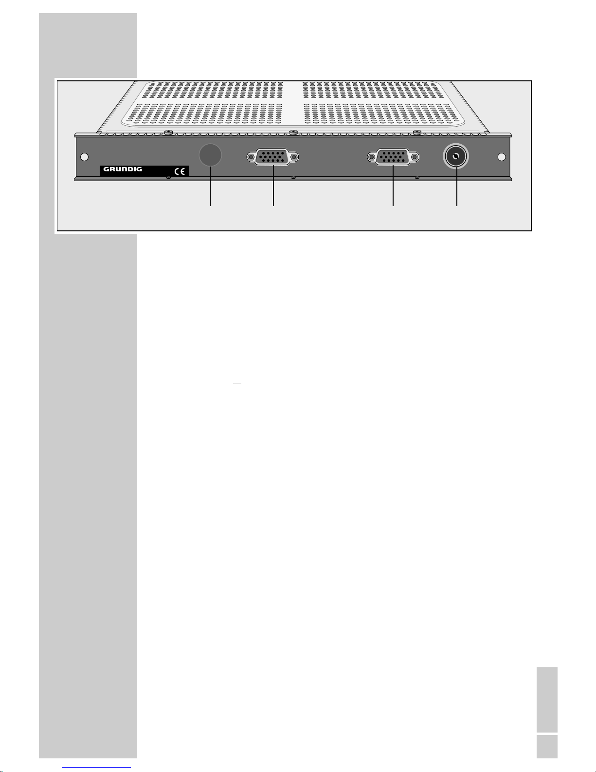
2 Plug the RF input cable into the RF input socket(s) SAT INPUT A and/or
SAT INPUT B (see Figure).
3 If the modulator has been equipped with one or two decoder interfaces:
connect external units via the respective connecting cables to the 15-pin
Sub-Min-D socket(s) DECODER A and/or DECODER B (see Figure).
4 Reconnect the Headend station to the mains supply.
– The installed modulator is now connected with all necessary supply voltages
and data lines and ready for use.
DECODER B
SAT INPUT A
DECODER A
SAT INPUT B (
retrofitting
)
Page 6
6
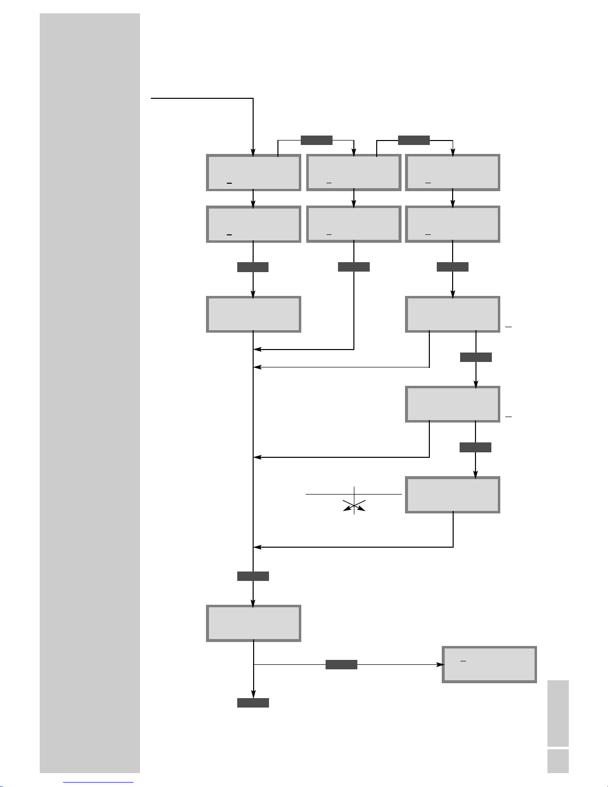
THE MENU GUIDE
____________________________________________________
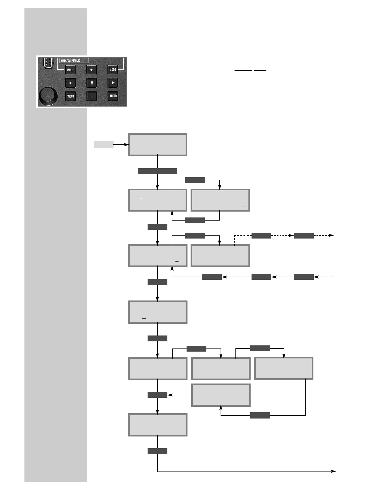
Note:
You may select the individual menus or menu items by pressing the MODE
key. To go back to the access menu without
saving the settings made, press the
MODE key longer than 2 seconds. When in a menu, use the
ľľ
and ııkeys
to select the desired setting, and then the
+ and
–
keys to change the settings.
Press the M key to save
all settings and to return to the access menu.
The following examples show the programming of the SAT receiver modulator PSAP 3000 VHF; the output channels S3 to S24 incl. C5 to C12
can be selected.
+
/
–
adjust picture/sound spacing
(normal, +1db, +2 db
or
-
1dB)
Bx 3A TUNER:
IF wide
Bx 3A DECODER:
PAL
Bx 3A INPUT:
1090.0 MHz
I
Decoder norm
(no function)
Ł
≥
2 sec.
+
/
–
Modulator
off/on
Bx 3A TWIN–SAT
Level HF Out: 0
Bx 3A TWIN–SAT
C5–C12 C12
BE–Remote V.19
please wait . . .
ON
+
/
–
select output
channel
Ł
≥
2 sec.
select Fine
+
/
–
Fine (Offset)
(+63/–64)
ĵ
back
Bx 3A OUTPUT:
C12 Fine 0
about 10 sec.
+
/
–
select box no.
(modulator)
continued on next page.
MODE
MODE
MULTI
V.19
Software version of the
Headend station’s
control unit
AUSGANGSKANÄLE
OUTPUT CHANNELS
M
ĵŁ
move cursor
+
/
–
enter input
frequency
Input frequency
<
–
I –>
too low
<– I –>
optimal
<– I
–
>
too high
MODE
MODE
+
/
–
select IF
bandwidth
(wide/narrow/DX)
MODE
–
/
+
adjust output level of
channel line A and B
( 0 to
-
7)
Ł
Bx 3A MODULAT:
Modulator on
Bx 3A MODULAT:
Depht: normal
MODE
Bx 3A MODULAT:
Pic/Snd: normal
+
/
–
set modulation depth
(normal,
-5%, -10%)
MODE
≥ 2 Sec.
MULTI
MULTI
MULTI
MULTI
MULTI
MULTI
Page 7
Bx 3A Change:
T1 7.02 T2 7.20
Bx 3A AUDIO–OUT:
Stereo Dual
ENGLISH
7
Bx 3A AUDIO–IN:
Deemphasis 50uS
Bx 3A AUDIO–IN:
7.02 MHz MAIN
Bx 3A TWIN–SAT
C5–C12 C12
THE MENU GUIDE
___________________________________________________________________
continued
Deemphasis
50 µS
75 µS
J 17
MULTI
select audio
mode (stereo,
mono, dual)
Bx 3A AUDIO–OUT:
Vol.
:
–
II
+
MODE
+
/
–
adjust
volume
Bx 3A AUDIO–IN:
7.02 MHz SubMONO
back to access menu
M
M
ODE
≥
2 sec.
reset all settings
M
save all settings
MODE
MULTI
Bx 3A AUDIO–IN:
7.02 MHz STEREO
MULTI
Bx 3A AUDIO–IN:
7.02
MHz MAIN
Bx 3A AUDIO–IN:
7.02 MHz SubMONO
Bx 3A AUDIO–IN:
7.02 MHz STEREO
MODE
+
/
–
select audio
deemphasis
Bx 3A VPS:
autom. manuell
MODE
MODE
MODE
MODE
+
/
–
select
autom.atic
or
manual
+
/
–
select
stereo
or
dual
+
/
–
assign
sound
subcarrier
(accompanying
sound)
+
/
–
enter audio
frequency
Example:
5.5 MHz 5.74 MHz
7.02 MHz 7.20 MHz
Change: 7.20 MHz 7.02 MHz
Page 8
SETTINGS
___________________________________________________________________________
8
Programming the receiver modulator
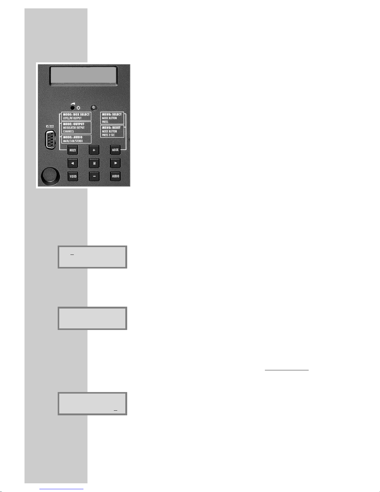
Programming of the receiver modulator is effected exclusively via the keys of the
basic module carrier’s control unit.
The user is guided via the two-line display on the control unit.
1 The following menu items can be selected using the MODE button:
– Modulator (Box no.) and channel line A or B.
– Output cannel /fine tuning (offset)
– Input frequency including fine tuning
– Decoder (without function)
– IF bandwidth (wide, narrow, dx)
– Main carrier/subcarrier (Main/SubMono/Stereo)
– Carrier frequency (5.00…9.77 MHz)
– Various audio settings
– Volume adjustment
Note:
The following examples show the programming of the SAT receiver modulator PSAP 3000 VHF; the output channels can be adjusted from S3 to S24
including C5 to C12.
Select modulator (Box no. and Line A or B)
1 A few moments after switching the Headend station on, the access menu, e.g.
»Box 3A TWIN–SAT« appears in the control unit’s display.
2 Use the + or
–
button to select the desired modulator (Box no.) and the
desired Line »A« or »B« .
Select the output channel
1 Press the MODE button. The »OUTPUT:« menu appears in the display.
2 Press the MULTI button to call up the programmed output channels.
3 Use the + or
–
button to select the desired output channel.
Adjust the frequency offset (fine tuning)
Caution:
The frequency offset should only be changed in exceptional cases as otherwise
all TV sets connected to the cable system must corrected accordingly using the
fine tuning facility.
1 Press the ı button until »Fine 0« also appears in the display, and then use the
+ or
–
button to select a different value.
Press the ľ button to return to the initial setting.
Bx 3A TWIN–SAT
C5–C12 C12
Bx 3A OUTPUT:
C12 Fine 0
Bx 3 OUTPUT
C12
BE–Remote V.19
PROFESSIONAL
Page 9
ENGLISH
9
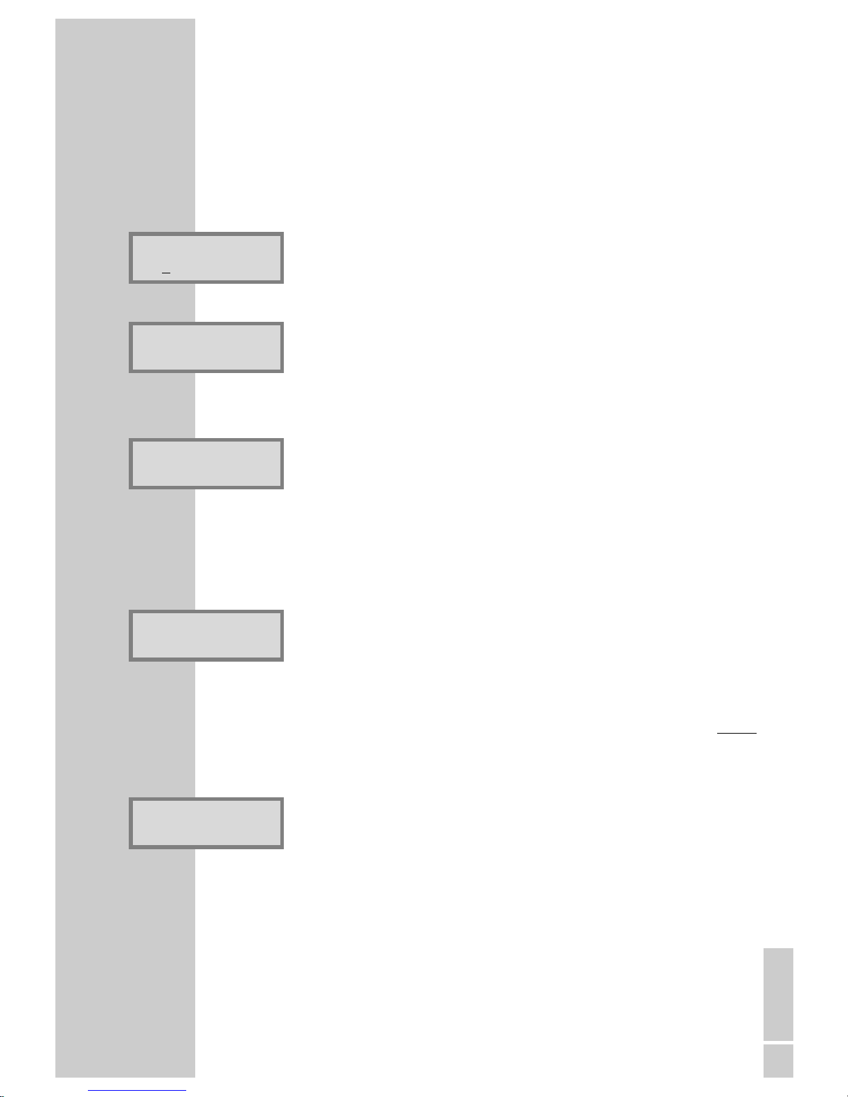
Enter the input frequency
1 Press the MODE button. The » INPUT:« menu appears in the display.
2 Use the ľ or ı button to move the cursor to the desired position, and then use
the + or
–
button to enter the input frequency.
Meaning of symbols:
<–
I
–>
= too low input frequency
<–I–>
= too high input frequency
<–I–>
= optimum input frequency
Select the decoder menu
1 Press the MODE button. The » DECODER:« menu appears in the display.
– The Deemphasis setting has no function for this modulator.
Select the modulator menu
1 Press the ı button until the »Box 3A MODULAT:« menu, for example,
appears in the display.
2 Use the + or
–
button to switch the respective modulator off or on again.
Select the modulation depth
On pictures with audio hum, it is possible to cut the modulation depth.
1 Press the MODE button. The »MODULAT:« menu and for example
»
Depth: normal«appear in the display.
2 Use the + or
–
button to adjust the appropriate modulation depth
(normal,
-
5%, or -10%).
Select the picture/sound spacing
In the event of eventual moireé interferences, it is possible to cut the second
sound carrier (5.74MHz).
1 Press the MODE button. The »MODULAT:«. menu with, for example,
»
Pic/Snd: normal
« appears in the display.
2 Use the + or
–
button to adjust the optimum picture/sound spacing
(+1 dB,
+2 dB, –1dB, or normal).
continued on next page
SETTINGS
__________________________________________________________________________________
Bx 3A DECODER:
PAL
Bx 3A MODULAT:
on
Bx 3A MODULAT:
Pic/Snd: normal
Bx 3A MODULAT:
Depth: normal
Bx 3A INPUT:
1090
.0 MHz
I
Page 10
10
SETTINGS
__________________________________________________________________________________
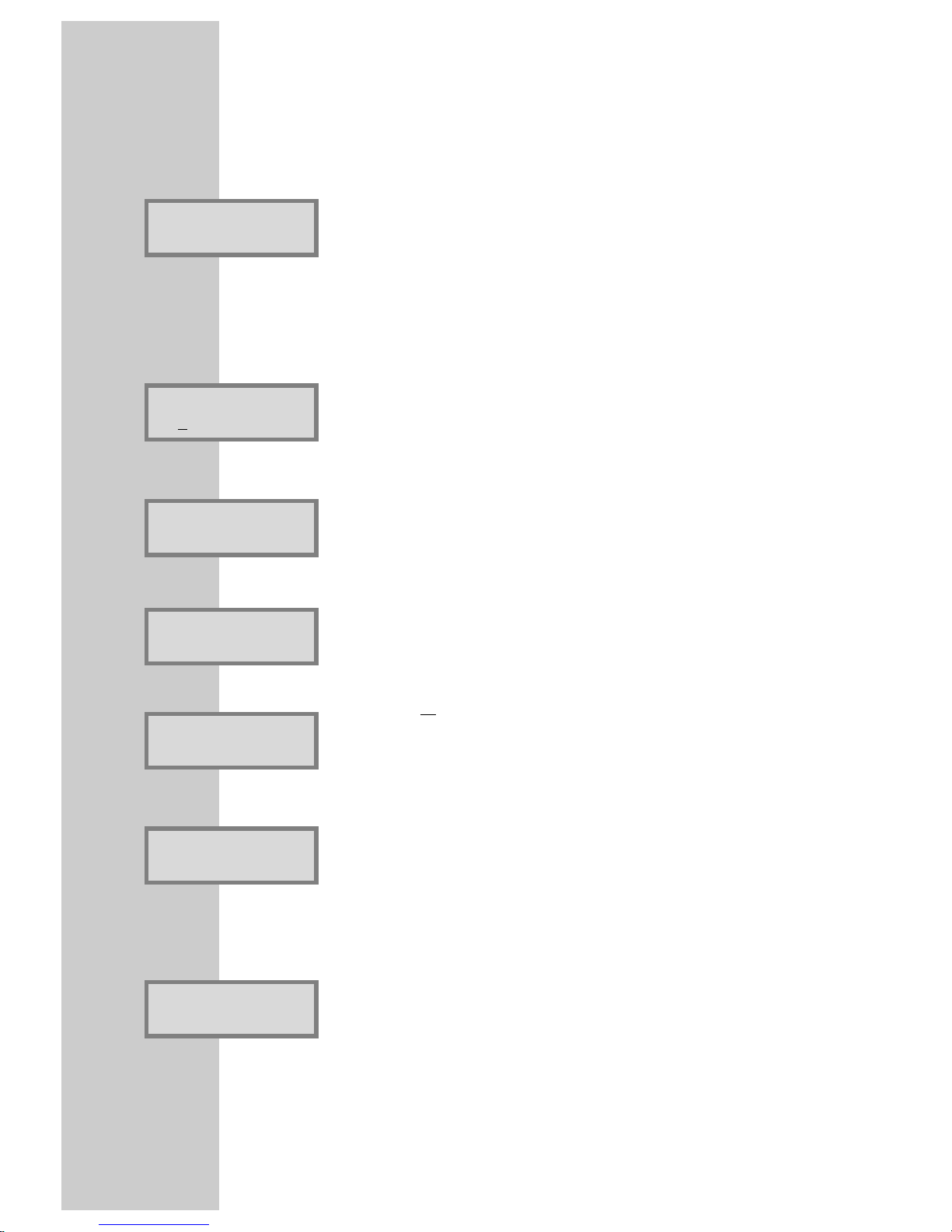
Select the IF bandwidth (threshold)
The IF bandwidth should only be changed if reception is poor.
1 Press the MODE button. The »TUNER:« menu appears in the display.
2 Use the + or
–
button to adjust the picture and sound to suit your taste
(wide, narrow, DX).
Select the audio mode and sound frequency (input)
1 Press the MODE button. The »AUDIO-IN:« menu appears in the display.
2 Use MULTI button to select the audio modes »MAIN«, »SubMONO« or
»STEREO« .
3 Use the ľ or ı button to move the cursor to the desired position. Then use
the + or
–
button to select the desired sound frequency.
Change the deemphasis in the »MAIN« audio mode
1 Press the MODE button. The »AUDIO-IN:« menu appears in the display.
2 Use the + or
–
button to select the audio settings »50 µS«, »75 µS« or »J17«.
In the »STEREO« audio mode
1 Press the MODE button. The »VPS:« menu appears in the display.
Note:
If the indications »autom.« and »NO IDENT« appear, the station is broadcasting no
VPS code.
In this case, select the »manual« option.
2 Use the
+ or
–
button to select the »autom.« or »manual« option.
Select stereo/dual with the »manual« setting
1 Press the MODE button. The »AUDIO-OUT:« menu appears in the display.
2 Use the + or
–
button to select the audio settings »Stereo« or »Dual«.
Change sound 1/sound 2 with the »Dual« setting
1 Press the MODE button. The »Change:« menu appears in the display.
2 If necessary or desired:
Use the + or –button to change the audio frequencies »T1 7.02 ɴ 7.20«
and »T2 7.20 ɴ 7.02«.
Bx 3A Change:
T1=7. 02 T2=7.20
Bx 3A AUDIO-OUT:
Dual
Bx 3A VPS:
autom. NO IDENT
Bx 3A VPS:
manuell
Bx 3A AUDIO-IN:
Deemphasis 50 uS
Bx 3A AUDIO-IN:
7.02
MHz STEREO
Bx 3A TUNER:
IF wide
Page 11
ENGLISH
11
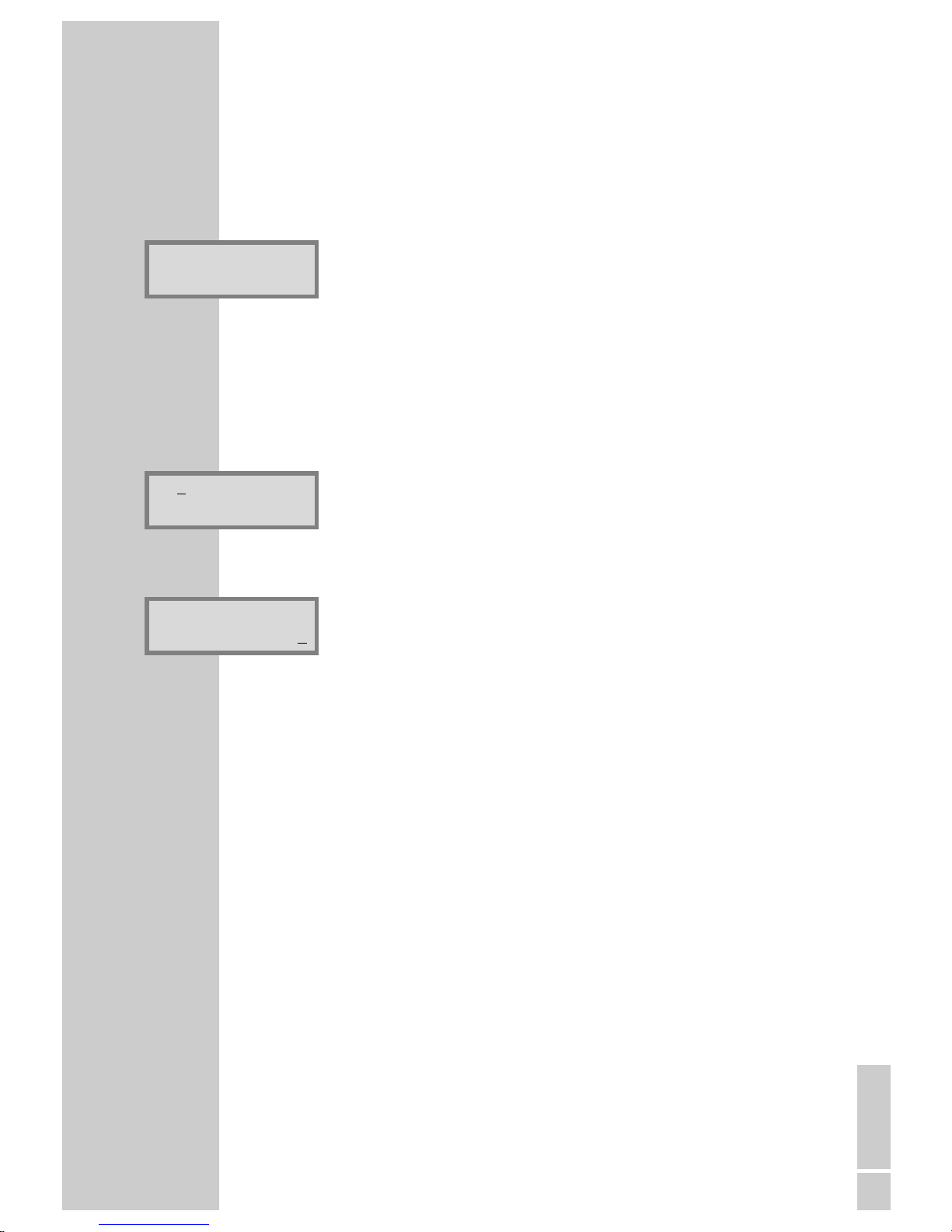
Adjust the volume level
It is possible to adjust different volume levels of the programmed stations to each
other.
The adjustment is possible in six volume steps.
1 Press the MODE button. In the display appears, for example, the menu
»Bx 1A AUDIO-OUT:«.
2 Use the + or
–
button to adjust the volume levels to each other.
Attention:
To restore the initial volume settings, press the MODE button until the access
menu, for example »Bx 3A TWIN–SAT« reappears.
Then use the + or
–
button to select another modulator (e.g. »Bx 1«).
– The initial values are restored.
Save all settings
1 Press the M button to save all new settings.
– The access menu, for example »Bx 3A TWIN–SAT«, reappears in the
display.
Adjust the output level of channel line A to line B
1 Press the MULTI button. The »Level HF Out:« menu appears in the display.
2 Use the + or
–
button to adjust the RF output level of channel line »A« to
line »B« (from 0 to –7 dB).
3 Press the M button to save the setting.
– The access menu, for example »Bx 3A TWIN–SAT«, reappears in the
display
Bx 3A AUDIO-OUT:
Bx 3A TWIN–SAT
C5–C12 C12
SETTINGS
__________________________________________________________________________________
Bx 3A TWIN–SAT
Level HF Out: 0
Page 12

12
IMPORTANT INFORMATION
_________________________
The VPS code
TV programmes are broadcast in the audio modes mono, stereo or two-channel
sound (dual).
Many TV stations identify these different audio modes by the VPS signal (VPS =
Video Programme System).
The SAT receiver modulator recognizes this signal and automatically switches to
the corresponding audio mode.
TV stations which are not broadcasting such identifiable signals do not change
the audio mode. This must be done manually in this case.
Particularities in the »AUDIO« menu . . .
. . . for the audio modes »MAIN« (main carrier, »SubMONO«, »STEREO«
and »DUAL« (= dual-channel sound):
1 When selecting »MAIN« (main carrier), no particularities must be observed.
After selecting the frequency, only the appropriate deemphasis must be
selected and the volume adjusted.
2 The »SubMONO« audio mode is selected if the TV sound is transmitted in
mono on a frequency of 7.02 or 7.20 MHz etc.
3 In the »STEREO« audio mode, only the lower sound carrier of the respective
stereo pair 7.02/7.20 MHz or 7.38/7.56 MHz etc. is selected.
– The upper sound carrier is then automatically received on a frequency
which is 180 kHz higher.
4 If the option »autom.« is selected in the following «VPS» menu, and if the
indications »Stereo«, »Dual« or »Mono« appear in addition, then the
receiver modulator recognizes the correct VPS code and switches automatically to the corresponding audio mode.
5 In the following »AUDIO OUT« menu, the »Stereo« or »Dual« (two-channel
sound) audio modes now must be selected manually.
– »Stereo« is selected for stations transmitting the audio signals on the sound
subcarriers and which are transmitting no
identifiable signals.
– »Dual« is selected for stations which are transmitting different languages
on the sound subcarriers
Please note that the appropriate lower sound carrier (7.02/7.20) can be
assigned the output sound carrier 5.5 MHz or 5.74 MHz via the »Change «
option in the AUDIO menu.
6 For example, to assign the German TV sound of 7.20 MHz to the 5.5 MHz
sound carrier of the “EUROSPORT“ channel, it is necessary to exchange
the frequencies in the AUDIO menu option »Change «.
7 With the last menu option »AUDIO-OUT Vol.:«, it is possible to adjust
the volume level of the various receiver modulators to the volume level of the
tuned stations.
Page 13

ENGLISH
13
ACCESSORIES
__________________________________________________________________
The decoder retrofit kit DNS UNIVERSAL,
Order no. GAG 2200.
General
The decoder retrofit kit DNS UNIVERSAL serves for retrofitting also analog
GRUNDIG PROFI cassettes PSAP 1000, PSAP 3000, PSAP 4000 and
PSAP 5000.
Important:
Contrary to the indications in the mouniting instructions of the retrofit kit, the
adapter plate supplied is not
required for the installation into this cassette.
The following units can be connected to this retrofit kit:
– a licenced decoder (descrambler)
– a video recorder (e.g. for use in a hotel), or
– a video camera (e.g. for monitoring a playground).
It provides the function of coupling in and out the video and audio signals.
In addition, this retrofit kit can remotely be controlled via a 0/12 V switching
voltage, for example, to switch between the signals from a monitor camera and
the satellite TV and radio programmes.
The external equipment is switched via the 12 V switching voltage input, pin 3 of
the Sub-D socket, into the signal path
Most decoders/descramblers, video recorders or video cameras, deliver a 12 V
switching voltage at contact 8 of the EURO/AV socket.
If the external equipment does not deliver a 12 V switching voltage, refer to the
section “Feeding the picture/sound signals of external equipment permanently
into the signal path”.
Continued on next page.
Page 14
14
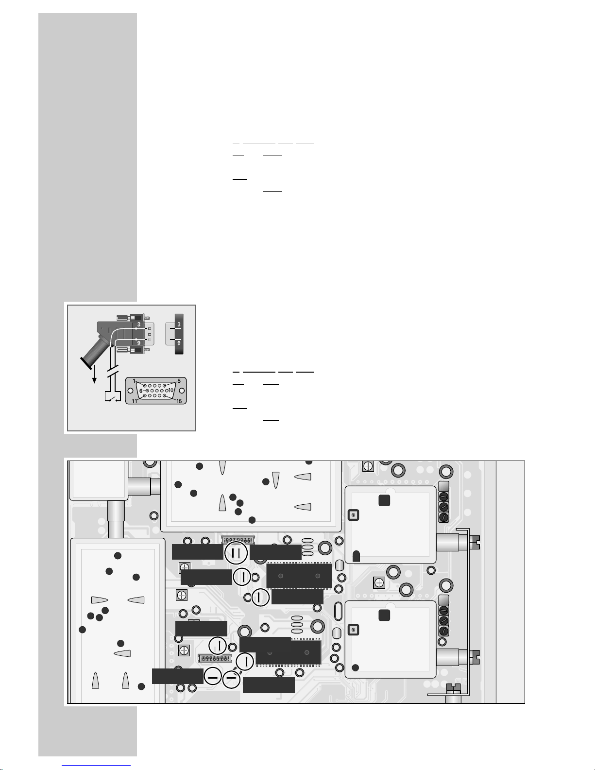
Feeding the picture/sound signals of external equipment permanently into the signal path
1 Fit the decoder module and the required flat ribbon cable.
In addition you must
cut the three wire bridges BR 1068 (Audio, right), BR 1093 (Audio, left)
and BR 1094 (Video), for channel LINE A
and
cut the thr
ee wire bridges BR 2068 (Audio, right), BR 2093 (Audio, left)
and BR 2094 (Video), for channel LINE B (see Figure below).
Remote switching
It is possible to remotely switch between the picture/sound signals of the SAT
programmes and the external equipment.
Switching can be effected, for example, manually or via a timer or via a
dimming switch.
1 Connect the switch inside the 15-pin plug of the enclosed adapter cable to
the pin 9 (12 V/10 mA switching voltage) and to the pin 3 (see Figure).
2 Fit the decoder module and the required flat ribbon cable.
In addition you must
cut the four wire bridges BR 1068 (Audio, right), BR 1093 (Audio, left),
BR 1094 (Video), and BR 1095 “Dec – off ”, for channel LINE A
and
cut the four wire bridges BR 2068 (Audio, right), BR 2093 (Audio, left),
BR 2094 (Video), and BR 2095 “Dec – off ”, for channel LINE B (see Figure
below).
EURO-AV
front of plug
socket
BR01093
BR01068
BR02068
BR02093
BR02094
BR02095
BR01094
BR01095
BR 1095
BR 1094
BR 1068
BR 1093
BR 2068
BR 2093
BR 2094
BR 2095
ACCESSORIES
___________________________________________________________________________
Page 15
ENGLISH
15
ACCESSORIES
___________________________________________________________________________
Video-controlled memory
If external picture/sound signals are to be per
manently fed in (without
switching voltage), we recommend to feed in the picture/sound signals via
pin 10 of the Sub-D socket.
In this case, the picture/sound signals are fed in a clam
ped and controlled way
into the modulator. In this way, output levels of different strength from the external
equipment are adjusted accordingly.
For that, on the component side of the chassis board, you must
cut the two wire bridges BR 1068 (Audio, right) and BR 1093 (Audio, left),
for channel LINE A
and
the two wire bridges BR 2068 (Audio, right) and BR 2093 (Audio, left),
for channel LINE B (see Figure on page 14).
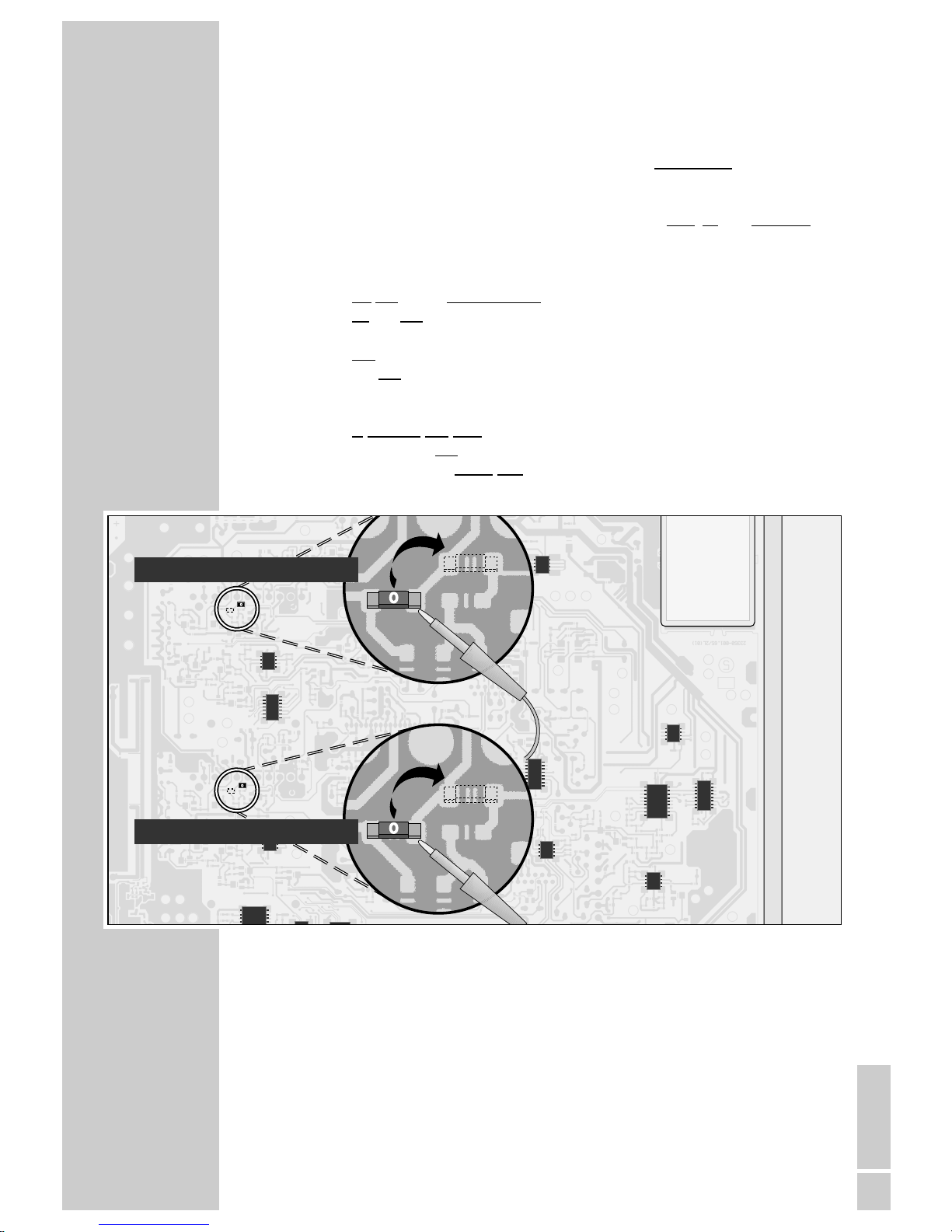
In addition you must
resolder the two chip bridges E (for channel LINE A) and F (for channel
LINE B) on the solder side of the cassette (see Figure below).
Chip brigde F (LINE B)
Chip brigde E (LINE A)
Continued on next page.
Page 16
16
ACCESSORIES
___________________________________________________________________________
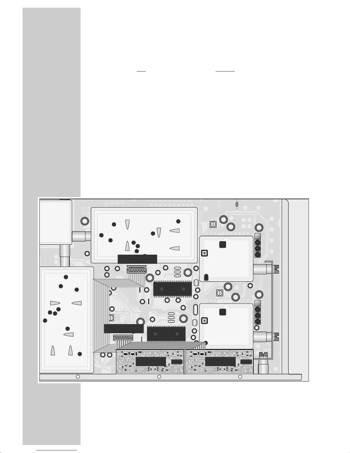
Installing the decoder retrofit kit into the cassette
Note:
Two decoder retrofit kits can be installed into each of the two twin SAT
cassettes: one for channel LINE A and one for channel LINE B.
1 Remove the cover from the top of the cassette.
2 Break out the corresponding pre-punched opening in the front side of the
cassette.
3 Plug one female connector of the flat ribbon cable into the corresponding
connector on the decoder retrofit kit.
4 Insert the decoder retrofit kit with the solder side up into the opening and fix
it with the screws enclosed.
5 Plug the other female connector of the flat ribbon cable into the corres-
ponding connector of the chassis board of the cassette.
6 Refit and fix the cover of the cassette.
Continued on next page.
DNS A
DNS B
Connector B
Connector A
Page 17
ENGLISH
17
BLANKING
__________________________________________________________________________
Blanking the picture signal
With pure sound transmissions (e.g. in hotel systems), the picture signal can be
blanked (dark picture).
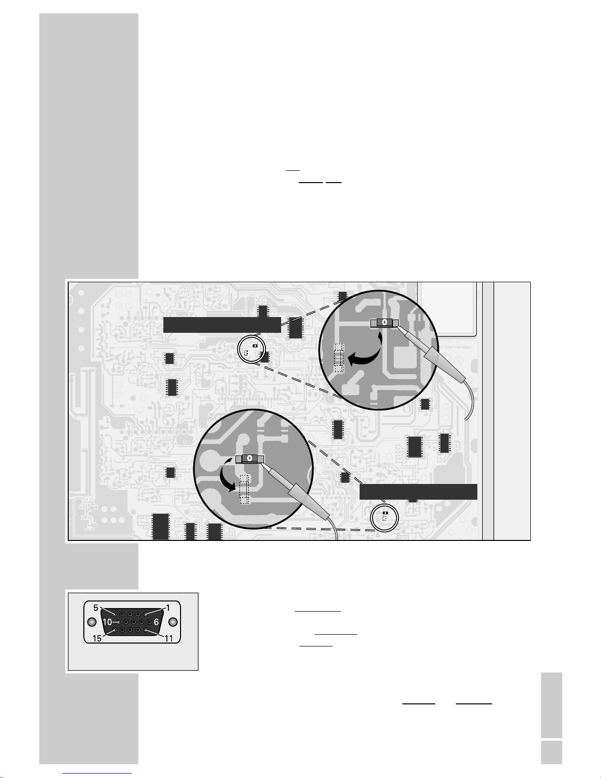
1 Remove the cover from the bottom of the cassette.
2 Resolder the two
chip bridges A (for channel LINE A) and B (for channel
LINE B) on the solder side of the cassette (see Figure below).
3 Refit and fix the cover to the bottom of the cassette.
4 Refit, fix and connect the cassette.
5 Tune to an analog satellite programme and feed in an external sound signal
via the 15 pin Sub-D socket.
Pin assignment of the Sub-D socket
01 = Audio input, left
02 = CCVS input, unregulated
03 = Switching voltage input, 12 V04 = Baseband output (unclamped, linear)
05 = CCVS output (clamped, PAL deemphasis)
06 = Audio input, right
07 = -08 = Ground
09 = Switching voltage output, 12 V-/10 mA
10 = CCVS input, external picture signals are clamped and regulated
11 = Ground
12 = Audio output, left
13 = Audio output, right
14 = -15 = --
front of socket
Chip bridge B (LINE B)
Chip bridge A (LINE A)
Page 18
18
C-BAND RECEPTION
________________________________________________
C-Band reception
With an appropriate satellite aerial and LNB this cassette can also receive
C-band stations (4 GHz).
For these stations, a negative video polarity must be selected.
1 Remove the cover from the bottom of the cassette.
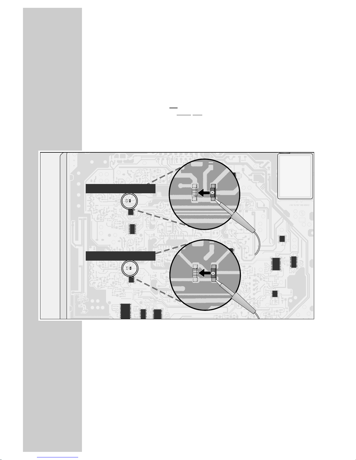
2 Resolder the two
chip bridges C (for channel LINE A) und D (for channel
LINE B) on the solder side of the cassette (see Figure below).
3 Refit and fix the cover to the bottom of the cassette.
4 Refit, fix and connect the cassette.
Chip bridge D (LINE B)
Chip bridge C (LINE A)
Page 19
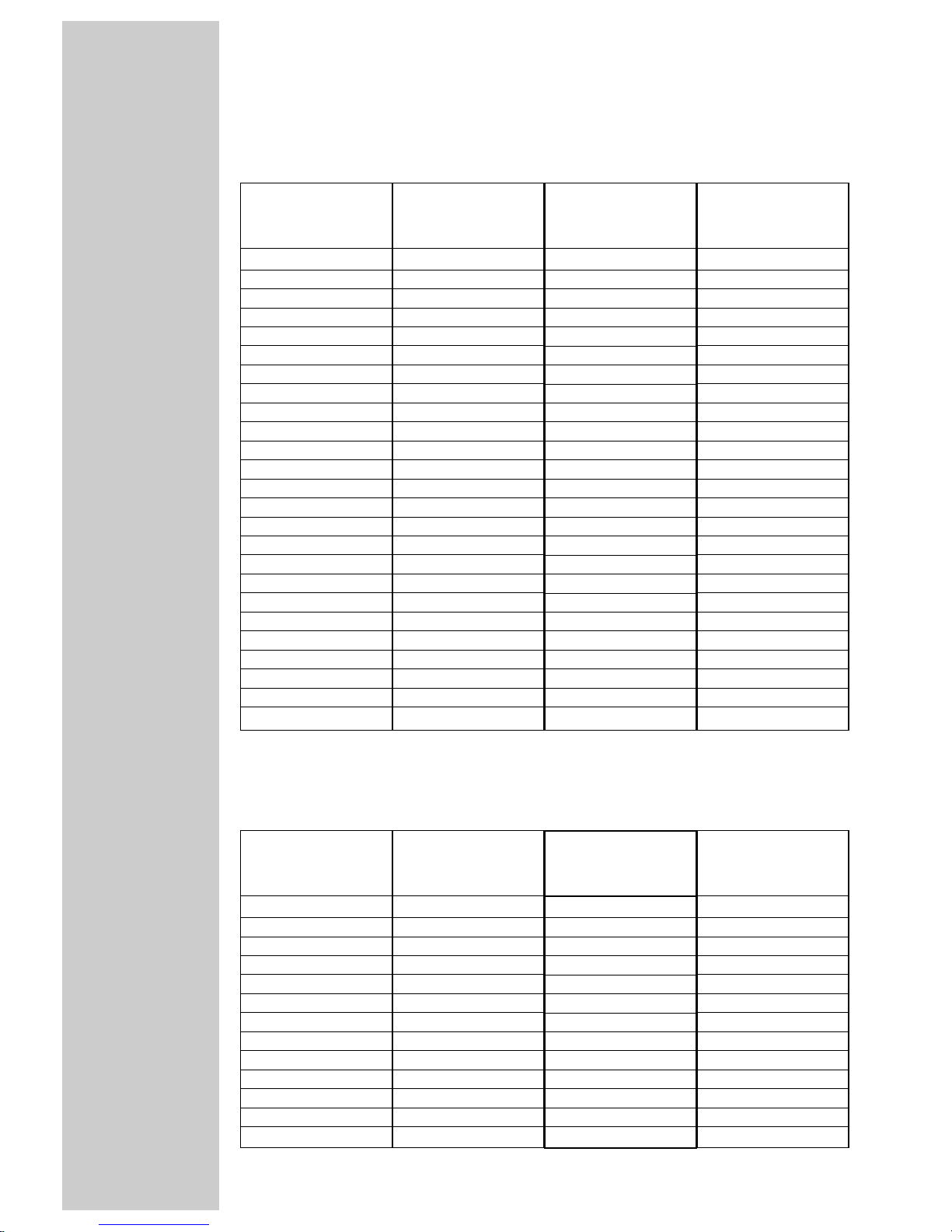
CCIR-Kanalraster/CCIR Channel Steps/Pas de canaux CCIR
Bild-/Ton-Abstand: 5,5 MHz / Video-audio distance: 5.5 MHz / Ecart vidéo/audio: 5,5 MHz
France-Kanalraster/France Chann. Steps/Pas de canaux en France
Bild-/Ton-Abstand: 6,5 MHz / Video-audio distance: 6.5 MHz / Ecart vidéo/audio: 6,5 MHz
Kanal Freq. BT in MHz
Chann. Frequ. in MHz
Canal Fréqu. en MHz
C 12 48,25
C 13 55,25
C 14 62,25
S 12 112,25
S 13 119,25
S 14 126,25
S 15 133,25
S 16 140,25
S 17 147,25
S 18 154,25
S 19 161,25
S 10 168,25
C 15 175,25
C 16 182,25
C 17 189,25
C 18 196,25
C 19 203,25
C 10 210,25
C 11 217,25
C 12 224,25
S 11 231,25
S 12 238,25
S 13 245,25
S 14 252,25
S 15 259,25
S 16 266,25
S 17 273,25
S 18 280,25
S 19 287,25
S 20 294,25
S 21 303,25
S 22 311,25
S 23 319,25
S 24 327,25
S 25 335,25
S 26 343,25
S 27 351,25
S 28 359,25
S 29 367,25
S 30 375,25
S 31 383,25
S 32 391,25
S 33 399,25
S 34 407,25
S 35 415,25
S 36 423,25
S 37 431,25
S 38 439,25
S 39 447,25
S 40 455,25
S 41 463,25
C 21 471,25
C 22 479,25
C 23 487,25
C 24 495,25
C 25 503,25
C 26 511,25
C 27 519,25
C 28 527,25
C 29 535,25
C 30 543,25
C 31 551,25
C 32 559,25
C 33 567,25
C 34 575,25
C 35 583,25
C 36 591,25
C 37 599,25
C 38 607,25
C 39 615,25
C 40 623,25
C 41 631,25
C 42 639,25
C 43 647,25
C 44 655,25
C 45 663,25
C 46 671,25
C 47 679,25
C 48 687,25
C 49 695,25
C 50 703,25
C 51 711,25
C 52 719,25
C 53 727,25
C 54 735,25
C 55 743,25
C 56 751,25
C 57 759,25
C 58 767,25
C 59 775,25
C 60 783,25
C 61 791,25
C 62 799,25
C 63 807,25
C 64 815,25
C 65 823,25
C 66 831,25
C 67 839,25
C 68 847,25
C 69 855,25
Kanal Freq. BT in MHz
Chann. Frequ. in MHz
Canal Fréqu. en MHz
Kanal Freq. BT in MHz
Chann. Frequ. in MHz
Canal Fréqu. en MHz
Kanal Freq. BT in MHz
Chann. Frequ. in MHz
Canal Fréqu. en MHz
Kanal Freq. BT in MHz
Chann. Frequ. in MHz
Canal Fréqu. en MHz
C 21 471,25
C 22 479,25
C 23 487,25
C 24 495,25
C 25 503,25
C 26 511,25
C 27 519,25
C 28 527,25
C 29 535,25
C 30 543,25
C 31 551,25
C 32 559,25
C 33 567,25
C 34 575,25
C 35 583,25
C 36 591,25
C 37 599,25
C 38 607,25
C 39 615,25
C 40 623,25
C 41 631,25
C 42 639,25
C 43 647,25
C 44 655,25
C 45 663,25
C 46 671,25
C 47 679,25
C 48 687,25
C 49 695,25
C 50 703,25
C 51 711,25
C 52 719,25
C 53 727,25
C 54 735,25
C 55 743,25
C 56 751,25
C 57 759,25
C 58 767,25
C 59 775,25
C 60 783,25
C 61 791,25
C 62 799,25
C 63 807,25
C 64 815,25
C 65 823,25
C 66 831,25
C 67 839,25
C 68 847,25
C 69 855,25
Kanal Freq. BT in MHz
Chann. Frequ. in MHz
Canal Fréqu. en MHz
Kanal Freq. BT in MHz
Chann. Frequ. in MHz
Canal Fréqu. en MHz
Kanal Freq. BT in MHz
Chann. Frequ. in MHz
Canal Fréqu. en MHz
GRUNDIG-SERVICE
__________________________________________________
Page 20
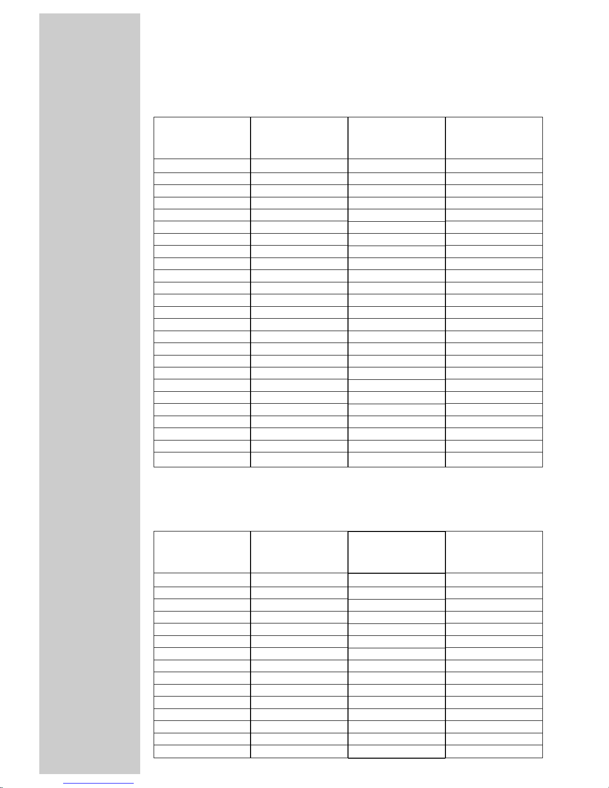
OIRT-Kanalraster/OIRT Channel Steps/Pas de canaux OIRT
Bild-/Ton-Abstand: 6,5 MHz / Video-audio distance: 6.5 MHz / Ecart vidéo/audio: 6,5 MHz
Kanal Freq. BT in MHz
Chann. Frequ. in MHz
Canal Fréqu. en MHz
R 11 49,75
R 12 59,25
R 13 77,25
R 14 85,25
R 15 93,25
s 11 111,25
s 12 119,25
s 13 127,25
s 14 135,25
s 15 143,25
s 16 151,25
s 17 159,25
s 18 167,25
R 16 175,25
R 17 183,25
R 18 191,25
R 19 199,25
R 10 207,25
R 11 215,25
R 12 223,25
s 19 231,25
s 10 239,25
s 11 247,25
s 12 255,25
s 13 263,25
s 14 271,25
s 15 279,25
s 16 287,25
s 17 295,25
s 18 303,25
s 19 311,25
s 20 319,25
s 21 327,25
s 22 335,25
s 23 343,25
s 24 351,25
s 25 359,25
s 26 367,25
s 27 375,25
s 28 383,25
s 29 391,25
s 30 399,25
s 31 407,25
s 32 415,25
s 33 423,25
s 34 431,25
s 35 439,25
s 36 447,25
s 37 455,25
s 38 463,25
C 21 471,25
C 22 479,25
C 23 487,25
C 24 495,25
C 25 503,25
C 26 511,25
C 27 519,25
C 28 527,25
C 29 535,25
C 30 543,25
C 31 551,25
C 32 559,25
C 33 567,25
C 34 575,25
C 35 583,25
C 36 591,25
C 37 599,25
C 38 607,25
C 39 615,25
C 40 623,25
C 41 631,25
C 42 639,25
C 43 647,25
C 44 655,25
C 45 663,25
C 46 671,25
C 47 679,25
C 48 687,25
C 49 695,25
C 50 703,25
C 51 711,25
C 52 719,25
C 53 727,25
C 54 735,25
C 55 743,25
C 56 751,25
C 57 759,25
C 58 767,25
C 59 775,25
C 60 783,25
C 61 791,25
C 62 799,25
C 63 807,25
C 64 815,25
C 65 823,25
C 66 831,25
C 67 839,25
C 68 847,25
C 69 855,25
Kanal Freq. BT in MHz
Chann. Frequ. in MHz
Canal Fréqu. en MHz
Kanal Freq. BT in MHz
Chann. Frequ. in MHz
Canal Fréqu. en MHz
Kanal Freq. BT in MHz
Chann. Frequ. in MHz
Canal Fréqu. en MHz
GB-Kanalraster/GB Channel Steps/Pas de canaux en GB
Bild-/Ton-Abstand: 6,0 MHz / Video-audio distance: 6.0 MHz / Ecart vidéo/audio: 6,0 MHz
Kanal Freq. BT in MHz
Chann. Frequ. in MHz
Canal Fréqu. en MHz
A 45,75
B 53,75
C 61,75
D 175,25
E 183,25
F 191,25
G 199,25
H 207,25
I 215,25
J 223,25
C 21 471,25
C 22 479,25
C 23 487,25
C 24 495,25
C 25 503,25
C 26 511,25
C 27 519,25
C 28 527,25
C 29 535,25
C 30 543,25
C 31 551,25
C 32 559,25
C 33 567,25
C 34 575,25
C 35 583,25
C 36 591,25
C 37 599,25
C 38 607,25
C 39 615,25
C 40 623,25
C 41 631,25
C 42 639,25
C 43 647,25
C 44 655,25
C 45 663,25
C 46 671,25
C 47 679,25
C 48 687,25
C 49 695,25
C 50 703,25
C 51 711,25
C 52 719,25
C 53 727,25
C 54 735,25
C 55 743,25
C 56 751,25
C 57 759,25
C 58 767,25
C 59 775,25
C 60 783,25
C 61 791,25
C 62 799,25
C 63 807,25
C 64 815,25
C 65 823,25
C 66 831,25
C 67 839,25
C 68 847,25
C 69 855,25
Kanal Freq. BT in MHz
Chann. Frequ. in MHz
Canal Fréqu. en MHz
Kanal Freq. BT in MHz
Chann. Frequ. in MHz
Canal Fréqu. en MHz
Kanal Freq. BT in MHz
Chann. Frequ. in MHz
Canal Fréqu. en MHz
GRUNDIG-SERVICE
__________________________________________________________________
Page 21
GRUNDIG-SERVICE
__________________________________________________________________
China-Kanalraster/China Channel Steps/Pas de canaux en China
Bild-/Ton-Abstand: 6,5 MHz / Video-audio distance: 6.5 MHz / Ecart vidéo/audio: 6,5 MHz
Kanal Freq. BT in MHz
Chann. Frequ. in MHz
Canal Fréqu. en MHz
D 11 49,75
D 12 57,75
D 13 65,75
D 14 77,25
D 15 85,25
Z 11 112,25
Z 12 120,25
Z 13 128,25
Z 14 136,25
Z 15 144,25
Z 16 152,25
Z 17 160,25
D 16 168,25
D 17 176,25
D 18 184,25
D 19 192,25
D 10 200,25
D 11 208,25
D 12 216,25
Z 18 224,25
Z 19 232,25
Z 10 240,25
Z 11 248,25
Z 12 256,25
Z 13 264,25
Z 14 272,25
Z 15 280,25
Z 16 288,25
Z 17 296,25
Z 18 304,25
Z 19 312,25
Z 20 320,25
Z 21 328,25
Z 22 336,25
Z 23 344,25
Z 24 352,25
Z 25 360,25
Z 26 368,25
Z 27 376,25
Z 28 384,25
Z 29 392,25
Z 30 400,25
Z 31 408,25
Z 32 416,25
Z 33 424,25
Z 34 432,25
Z 35 440,25
Z 36 448,25
Z 37 456,25
Z 38 464,25
D 13 471,25
D 14 479,25
D 15 487,25
D 16 495,25
D 17 503,25
D 18 511,25
D 19 519,25
D 20 527,25
D 21 535,25
D 22 543,25
D 23 551,25
D 24 559,25
D 25 607,25
D 26 615,25
D 27 623,25
D 28 631,25
D 29 639,25
D 30 647,25
D 31 655,25
D 32 663,25
D 33 671,25
D 34 679,25
D 35 687,25
D 36 695,25
D 37 703,25
D 38 711,25
D 39 719,25
D 40 727,25
D 41 735,25
D 42 743,25
D 43 751,25
D 44 759,25
D 45 767,25
D 46 775,25
D 47 783,25
D 48 791,25
D 49 799,25
D 50 807,25
D 51 815,25
D 52 823,25
D 53 831,25
D 54 839,25
D 55 847,25
D 56 855,25
D 57 863,25
Kanal Freq. BT in MHz
Chann. Frequ. in MHz
Canal Fréqu. en MHz
Kanal Freq. BT in MHz
Chann. Frequ. in MHz
Canal Fréqu. en MHz
Kanal Freq. BT in MHz
Chann. Frequ. in MHz
Canal Fréqu. en MHz
Page 22
USA-Kanalraster/USA Channel Steps/Pas de canaux en E.U. A.
Bild-/Ton-Abstand: 4,5 MHz / Video-audio distance: 4.5 MHz / Ecart vidéo/audio: 4,5 MHz
Kanal Freq. BT in MHz
Chann. Frequ. in MHz
Canal Fréqu. en MHz
c 12 55,25
c 13 61,25
c 14 67,25
c 15 77,25
c 16 83,25
A 121,25
B 127,25
C 133,25
D 139,25
E 145,25
F 151,25
G 157,25
H 163,25
I 169,25
c 17 175,25
c 18 181,25
c 19 187,25
c 10 193,25
c 11 199,25
c 12 205,25
c 13 211,25
J 217,25
K 223,25
L 229,25
M 235,25
N 241,25
O 247,25
P 253,25
Q 259,25
R 265,25
S 271,25
T 277,25
U 283,25
V 289,25
W 295,25
c 14 471,25
c 15 477,25
c 16 483,25
c 17 489,25
c 18 495,25
c 19 501,25
c 20 507,25
c 21 513,25
c 22 519,25
c 23 525,25
c 24 531,25
c 25 537,25
c 26 543,25
c 27 549,25
c 28 555,25
c 29 561,25
c 30 567,25
c 31 573,25
c 32 579,25
c 33 585,25
c 34 591,25
c 35 597,25
c 36 603,25
c 37 609,25
c 38 615,25
c 39 621,25
c 40 627,25
c 41 633,25
c 42 639,25
c 43 645,25
c 44 651,25
c 45 657,25
c 46 663,25
c 47 669,25
c 48 675,25
c 49 681,25
c 50 687,25
c 51 693,25
c 52 699,25
c 53 705,25
c 54 711,25
c 55 717,25
c 56 723,25
c 57 729,25
c 58 735,25
c 59 741,25
c 60 747,25
c 61 753,25
c 62 759,25
c 63 765,25
c 64 771,25
c 65 777,25
c 66 783,25
c 67 789,25
c 68 795,25
c 69 801,25
c 70 807,25
c 71 813,25
c 72 819,25
c 73 825,25
c 74 831,25
c 75 837,25
c 76 843,25
c 77 849,25
c 78 855,25
c 79 861,25
c 80 867,25
c 81 873,25
c 82 879,25
c 83 885,25
Kanal Freq. BT in MHz
Chann. Frequ. in MHz
Canal Fréqu. en MHz
Kanal Freq. BT in MHz
Chann. Frequ. in MHz
Canal Fréqu. en MHz
Kanal Freq. BT in MHz
Chann. Frequ. in MHz
Canal Fréqu. en MHz
GRUNDIG-SERVICE
__________________________________________________________________
Page 23

GSS Grundig SAT Systems GmbH • Beuthener Str. 43 • D-90471 Nürnberg • http://www.gss.tv
 Loading...