

Page 1

TV Service Manual
Chassis P6
Apollo
42 PW 110-7510 TOP GBD3700
42 PW 110-7505 TOP GBD3705
Xephia
42 PW 110-5510 TOP GBD6600
42 PW 110-5501 TOP GBD6700/GBD9800
42 PW 110-6501 TOP GBD3800
Page 2

GRUNDIG Service Chassis P6
Es gelten die Vorschriften und Sicherheitshinweise
gemäß dem Service Manual "Sicherheit", Materialnummer 720108000001, sowie zusätzlich die eventuell abweichenden, landesspezifischen Vorschriften!
Inhaltsverzeichnis
Seite
Allgemeiner Teil ................................... 1-2…1-5
Allgemeine Hinweise.................................................................... 1-2
Technische Daten ........................................................................ 1-3
Service- und Sonderfunktionen .................................................... 1-5
Platinenabbildungen
und Schaltpläne ................................. 2-1…2-61
Blockschaltplan ............................................................................ 2-1
Blockschaltplan Netzteil ............................................................... 2-2
Schaltplanübersicht ...................................................................... 2-3
– Teil 1 Dual Interface AD9887 ................................................... 2-5
– Teil 2 Audio - MSP3410 ........................................................... 2-7
– Teil 3 Audio - Input/Output ..................................................... 2-10
– Teil 4 PC/DVI-D - Input .......................................................... 2-12
– Teil 5 Video Decoder PIP ....................................................... 2-13
– Teil 6 LVDS Transmitter ......................................................... 2-14
– Teil 7 Flash Memory............................................................... 2-16
– Teil 8 Spannungsversorgung ................................................. 2-17
– Teil 9 Deinterlacer .................................................................. 2-19
– Teil 10 Image Processor ........................................................ 2-21
– Teil 11 SDRAM ...................................................................... 2-24
– Teil 12 Tuner .......................................................................... 2-25
– Teil 13 Video Decoder ............................................................ 2-27
– Leiterplatte Y51.190R-6 ......................................................... 2-28
– Leiterplatte Y51.190R-8 ......................................................... 2-41
Netzteil - R84.194R-3 ................................................................ 2-53
Netzteil - R82.194-06 ................................................................. 2-55
Line-Filter/Standby-Netzteil - R82.195-04.................................. 2-56
Netzteil - BW1.194R .................................................................. 2-57
AV-Adapter-Platte - R82.198-01 ................................................ 2-59
AV-Adapter-Platte - R82.198-02 ................................................ 2-60
Bedien-Platte - X24.193-01 ........................................................ 2-61
Lautsprecheranschluss-Platte - R82197-01............................... 2-61
The regulations and safety instructions shall be valid
as provided by the "Safety" Service Manual, part
number 720108000001, as well as the respective
national deviations.
Table of Contents
Page
General Section .................................... 1-2…1-5
General Notes .............................................................................. 1-2
Technical Data ............................................................................. 1-3
Service and Special Functions ..................................................... 1-5
Layout of PCBs
and Circuit Diagrams ......................... 2-1…2-61
Block Diagram .............................................................................. 2-1
Block Diagram Power Supply ...................................................... 2-2
Circuit Diagram Overview ............................................................ 2-3
– Part 1 Dual Interface AD9887 .................................................. 2-5
– Part 2 Audio - MSP3410 .......................................................... 2-7
– Part 3 Audio - Input/Output .................................................... 2-10
– Part 4 PC/DVI-D - Input.......................................................... 2-12
– Part 5 Video Decoder PIP ...................................................... 2-13
– Part 6 LVDS Transmitter ........................................................ 2-14
– Part 7 Flash Memory .............................................................. 2-16
– Part 8 Power Supply .............................................................. 2-17
– Part 9 Deinterlacer ................................................................. 2-19
– Part 10 Image Processor ....................................................... 2-21
– Part 11 SDRAM ...................................................................... 2-24
– Part 12 Tuner ......................................................................... 2-25
– Part 13 Video Decoder ........................................................... 2-27
– PCB Y51.190R-6 .................................................................... 2-28
– PCB Y51.190R-8 .................................................................... 2-41
Power Supply - R84.194R-3 ...................................................... 2-53
Power Supply - R82.194-06 ....................................................... 2-55
Line-Filter/Standby Power Supply - R82.195-04 ........................ 2-56
Power Supply - BW1.194R ........................................................ 2-57
AV Adaptor Board - R82.198-01 ................................................ 2-59
AV Adaptor Board - R82.198-02 ................................................ 2-60
Control Board - X24.193-01 ....................................................... 2-61
Speaker Connector Board - R82197-01 .................................... 2-61
Ersatzteillisten .................................... 3-1…3-11
Allgemeiner Teil
Allgemeine Hinweise
Achtung: ESD-Vorschriften beachten
Vor dem Öffnen des Gehäuses zuerst den Netzstecker ziehen!
Leitungsverlegung
Bevor Sie die Leitungen und insbesondere die Masseleitungen lösen,
muss die Leitungsverlegung zu den einzelnen Baugruppen beachtet
werden. Nach erfolgter Reparatur ist es notwendig, die Leitungsführung wieder in den werkseitigen Zustand zu versetzen um evtl.
spätere Ausfälle oder Störungen zu vermeiden.
Messwerte und Oszillogramme
Bei den in den Schaltplänen und Oszillogrammen angegebenen
Messwerten handelt es sich um Näherungswerte!
Achtung: Chassisvarianten
Einige Gerätetypen wurden sowohl mit Chassis P6 als auch mit Chassis P7 produziert. Für
Chassis P7 ist das Service Manual
720100494000 maßgebend. Auf dem Typenschild (Geräterückseite) ist die Chassisbezeichnung aufgedruckt. Beachten Sie hierbei
auch den Produktcode der links neben der
Seriennummer zu finden ist.
Spare Parts Lists ................................ 3-1…3-11
General Section
General Notes
Attention: Observe the ESD safety regulations
Before opening the cabinet disconnect the mains plug!
Wiring
Before disconnecting any leads and especially the earth connecting
leads observe the way they are routed to the individual assemblies. On
completion of the repairs the leads must be laid out as originally fitted
at the factory to avoid later failures or disturbances.
Measured Values and Oscillograms
The measured values given in the circuit diagrams and oscillograms
are approximates!
Attention: Chassis variants
Some types of sets are produced with chassis
P6 as well as with Chassis P7. For chassis P7
Service Manual 720100494000 is standard.
Type of chassis is printed on the type label (rear
side). Please also pay attention of the product
code which you can find left from the serial
number.
1 - 2
Page 3

Technische Daten / Technical Data
Order No.
EAN
Color
Remote control
IM-Languages
Destination
Display
Panel
16:9 wide-screen format
Panel driving technology
Response time (approx.)
Brightness (approx.)
Contrast ratio (approx.)
Viewing angle (approx.)
Physical display resolution
PICTURE
Digital Reference-Plus-Technology (Motion Adaption)
Line Flicker Reduction
Motion Adaptive Deinterlacing
Digital Color Transition Improv. (DCTI)
Digital Combfilter
Digital Luminance Transition Improv. (DLTI)
Picture Noise Reduction (DNR)
CCS (Clear Color Screen)
Preset picture modes
Aspect ratios (Format switching)
PIP
1 - 3
Multifold Tuner scan (Mosaic Picture)
PAT: Split screen (PICTURE + TEXT)
PAP: Double window (PICTURE + PICTURE)
P2AT: Double window + TXT
POP: PICTURE on PICTURE
Picture freezing
Zoom with point function
Auto 16:9 selection via Scart
Sharpness control
Blue Background
CHASSIS
TV-Chassis
Progressive
Tuner
Keyboard
ELECTRONIC
Stand by indicator
EPG (Electronic Programme Guide)
Easy Dialog
Megalogic
Manual & autom. labeling of prog.
Programmable off timer
Programmable on timer
Intelligent channel search (Zapping funct.)
Programme Edit
Intelligent Programme Switch
Auto switch off
Programme memory TV/AV (opt.)
Teletext/Fasttext/Toptext
Teletext options
Childlock
Youth free recognition
Menue languages OSD
OSD-style
SWAP (Recall function)
Xephia 42 PW 110-5510 TOP
H1Q, H8X, G5P, J2R
G.BD 66-00
40 13833-60126 5
D,GB,F,I,NL,DK,N,S,FIN,E,P,PL,T
R
All NSOs
Xephia 42 PW 110-5501 TOP
H1E
G.BD 98-00
40 13833-60171 5
glossy black/silver
TP 160 C
GR,CIS,PL,CZ,BG
BG,CIS, CZ,GR,PL
1000cd/m2
Zoom shift by menue
6 keys: menue, source, ± for programme, ± for volume
Grundig-style
Xephia 42 PW 110-5501 TOP
H1N, J1H
G.BD 67-00
40 13833-60127 2
D,GB,F,I,NL,DK,N,S,FIN,E,P,PL,T
22 languages, D, GB, F, I, E, P, NL, HR, RUS, GR, DK, S, FIN, N, TR, PL, CZ, SK, SLO, H, RO, BG
R
All NSOs without BG,CIS,
CZ,GR,PL
Auto (WSS), 4:3 / 14:9 / 16:9 / Panorama / L.box / SubT
Xephia 42 PW 110-5500 TOP
42" / 106 cm Plasmatron Plasma Display
160° vertical / 160° horizontal
Yes, user, natural, rich, soft
PLL frequency synthesizer tuning
F6N
G.BD 59-00
40 13833-60091 6
silver / black
D,F,NL
D,F,B,NL
[
\
\
3.000:1
WXGA 852 x 480
[
[
[
[
[ (2D)
[
[
\
[ 2-Tuner PIP
\
[
[
\
\
[
[
[
\
L6B (P6)
[
red LED
\
\
\
[
[
\
[
[
\
\
99 / 6
[ / [ / [
800 pages
[
\
[
TP L6B
1500cd/m2
OEM-style
42 PW 110-6501 TOP
G8T
G.BD 38-00
40 13833-60027 5
silver silver / black
D
D
\
Apollo 42 PW 110-7510 TOP
G7L
G.BD 37-00
40 13833-60026 8
D,GB,F,I,NL,DK,N,S,FIN,E,P,PL,TR
1000cd/m2
Zoom shift by menue
\\
Grundig-style
Apollo 42 PW 110-7505 TOP
TP 160 C
All NSOs
G8W
G.BD 37-05
40 13833-60160 9
Chassis P6GRUNDIG Service
Page 4

Service mode
g
Hotel mode
TUNING
Autom. Tuning System with country selection
Frequency Based Auto Search
Automatic Micro-search
Automatic Programming
Manual fine tuning
Direct channel selection
Direct frequency selection
PAL/SECAM/BG/DK/I/L'/L
NTSC-Playback via Scart (3,58/4,43)
PAL M/N, NTSC M
Cable TV / Hyperband (S1-S41)
AUDIO
Mono/Stereo/Nicam
AV Stereo
Loudspeaker
Virtual Dolby
Matched Sound Delay (Lip synchronous)
Subwoofer
Dynamic Bass
DSP (Digital Sound Processor)
Balance Adjustment
AVL (Audio Volume Level)
PIP listening via Headphone.jack
Equalizer
Space Sound Effect
Audio mode
Audio amplifier without extern LS
POWER SUPPLY / CABINET
Power voltage
Power switch
1 - 4
Integrated supply
Plug-in AC adaptor
Power consumption
Cabinet (WxHxD) / Weight (approx.)
REAR PANEL CONNECTIONS
Euro-AV-Socket AV1
Euro-AV Socket AV2
Euro-AV Socket AV3
S-Video
Camera-AV
Wireless
YUV input / progressive
PC-input (Sub D 15)
PC-Audio in
DVI
HDCP
HDMI
Headphones
Video out
Audio out
Antenna for terrestrial reception
DC-connector
Power supply plug
Remote control (incl. battery)
Power cord
Xephia 42 PW 110-5510 TOP
H1Q, H8X, G5P, J2R
Xephia 42 PW 110-5501 TOP
H1E
Xephia 42 PW 110-5501 TOP
H1N, J1H
Xephia 42 PW 110-5500 TOP
full automatic sorting
2 wide band extern 2 wide band internal
2 x 14 / 7 W
(music/nominal)
2 x 10 / 5 W (music/nominal)
cinema, music, sport, speech, user
[
253 W, standby 6 W in accordance to IEC 62087-2002
125,0 x 75,0 x 10,0cm / 43,4kg 105,5 x 74,0 x 10,5 cm (24,7 cm with stand) / 39,4 kg
CVBS in-/output, RGB input
1 x Coaxial-socket for TV-tuner-in, according to DIN 45325
F6N
[
\
[
[
\
[
[
\
[/[/[/[/[/[/[
[
\
[
[ / [ / [
[
\
\
\
\
\
[
[
\
5 Band
\
230V~, 50/60 Hz
\,
stand-by switch
[
\
CVBS in-/output
\
Hosiden
3x Cinch socket in
\
\
Multisync WXGA
[
DVI-D
\
\
\
1 x Cinch
2 x Cinch
\
[
[
[
42 PW 110-6501 TOP
G8T
Apollo 42 PW 110-7510 TOP
G7L
2 wide band extern 2 wide band internal
2 x 14 / 7 W (music/nominal) 2 x 10 / 5 W
[
134,5 x 72,5 x 10,5 cm (24,5 cm with stand) / 43,6 kg
Apollo 42 PW 110-7505 TOP
G8W
(music/nominal)
106,8x72,5x
10,5cm (24,5cm with stand) /
34,7k
Chassis P6GRUNDIG Service
Page 5

Chassis P6GRUNDIG Service
Service- und Sonderfunktionen
Tastenfunktionen TP160C (TP L6B)
i (MENU)
P+ (Q)
/
P- (R)
ǸǸ
ǸǸ
Service-Mode aktivieren
– Tast e "
– Service Nummer "8500" ("9301") eingeben.
Service-Mode beenden
– Tast e "
Software-Versionsnummer
Im Service Menü "version" wird die Versionsnummer angezeigt.
ǷǷ
( O ) /
ǷǷ
ken. Menü "bild" wird eingeblendet.
ken.
Service Menus
display
factory mode
panel
power on time
back light time
scart prescale
nicam prescale
fm/am prescale
agc adjust
red brightness
red contrast
green brightness
green contrast
blue brightness
blue contrast
calibre
video format
color space
test pattern
color components
solid field level
initial ats
factory reset
dpms
osd time out
backlight
child lock mode
- Aufrufen des Service Menü
- Menü-Punkt aktivieren
- Untermenü verlassen
- Menü-Zeile (Menüpunkt) wählen
( P ) - Untermenü auswählen
- Wert ändern
i" ("MENU")
i" ("MENU")
auf der Fernbedienung drük-
auf der Fernbedienung drük-
off
1280x768
xx:xx:xx
xx:xx:xx
25
45
24
16
128
128
128
128
128
128
automatisch/auto
RGB
keine/none
all
33
aus /off
press <ok> to reset
ein/on
60 sec
15
off
only for use in factory
Shows the panel resolution. It is a read only option and can not be set.
LCD TVs only: Gives information about the last update time of the SW running. It is a read only
option and can not be set.
LCD TVs only: Backlight on time option reserved.
Sets the prescale values for the input sounds entering the scart input of the MSP (Micronas Sound Processor). Changing this value you can adjust the level of the output sound going to
loudspeakers for all the sources except the Tuners. The range is between 0 and 100.
Sets the prescale values for the Nicam standard sounds for tuner inputs. Changing this value you
can adjust the level of the output sound going to loudspeakers for Nicam sounds entering the analog sound input of MSP. The range is between 0 and 100.
Sets the prescale values for the FM/AM standard sounds for tuner inputs. Changing this value you
can adjust the level of the output sound going to loudspeakers for FM/AM sounds entering the
analog sound input of MSP. The range is between 0 and 100.
Sets the input voltage going to IF decoder AGC pin. Changing this value you can adjust this voltage for optimum Tuner performance. The range is between 0 and 31.
These are used for color bias adjustment. The range is between 0 and 255
Forces the video format to the desired format. Selectable formats are Auto, PAL, NTSC and SECAM.
Gives information about the video colorspace input to PW181 IC. Do not change this value unless
an error occurred in the colors displayed.
Activates the internal pattern of PW181 IC. There are 3 choices: none, vert bars, solid color. None
will deactivate the internal pattern. Vert bars choice activates the bar pattern for the selected color
component. Solid color activates the solid pattern with one color selected in color component and
also you can change the level of the color by solid field level.
Selects the color for the internal pattern of PW181 IC. There are 4 choices: all, red, green and
blue. If you choose all, you can see the white pattern and if you choose one of the other choices
you can see the test pattern with the selected color.
This option will adjust the level of the colors for the test pattern. The range is between 1 and 64.
This option will enable or disable the Initial setup for the TV. Setting this option to On, the TV will
open from the Quick setup menu. Setting this option to Off will disable this option.
Factory reset option executes a reset operation for the NVRAM. Pressing OK when this option is
selected will erase the NVRAM and load default values to NVRAM.
This option selects the Power option for the TV. Setting this option to On the TV will switch to the
last state for power on transition. Setting this to Off will disable this option and the TV will always
switch to Stand-by state while power on transition.
This option sets the OSD timeout for the main menu structure. Selections are 5, 15 and 60 secs.
The default is 60 sec.
Intensity of the backlight
sets with keyboard - on; sets without keyboard - off
TP 160 C TP L6B
Service and Special Functions
Functions of the buttons TP160C (TP L6B)
i (MENU)
P+ (Q)
/
P- (R)
ǸǸ
ǸǸ
Calling up the Service Mode
– Press button "
– Enter service code "8500" ("9301").
Exit the Service Mode
– Press button "
Software Version Number
The software version number is shown in service
menu "version".
ǷǷ
( O ) /
ǷǷ
Menu "picture" appears.
- Call up the Service Menu
- Activate menu point
- leave submenu
- Call up the dialogue line
(point of menu)
( P ) - Select submenu
- changing the settings
i" ("MENU")
i" ("MENU")
on the remote control.
on the remote control.
Die angegebenen Werte sind Mittelwerte, die abhängig vom LCD-Panel abweichen können.
Bei Austausch der Speicher oder der Chassisplatte
muss die zum LCD-Panel passende Software installiert werden.
The above specified values are averages and can
vary dependend on the LCD panel.
A software which corresponds with the LCD panel
must be programmed after changing the memory or
the chassis.
1 - 5
Page 6

SCART 1 2 3
AUDIO PROCESSOR
MSP3410D
Audio Amplifier
TA2024
Headphone
Amp.
TDA1308
Tuner-Main
Tuner-PIP
IF IC TDA9886T
IF IC TDA9886T
Video Switch
TDA6415C
PIP-Video
Main-Video
Video In/Out
Audio-In/Out
Audio-Switch
TDA6420
Pin 8 Switch
PCF8591
RGB Switch
PI5V30
AV4 Video-In
AV4
Audio-In
AV-Out Video
AV Out Audio
PC DVI Audio -In
Audio
In-Out
SC1-SC2 RGB
Headphone Jack
Speaker
QSS-Main
QSS-PIP
I2C Communication
Video-PIP
Video-Main
Scart RGB
SVHS Y/C
Multi Standard
Video Decoder
SAA7118MP
Multi Standard
Video Decoder
SAA7118MP
EEPROM
24LC21
EEPROM
24LC21
Dual Interface for
FPD
AD9887
RGB HS/VS-In
DVI Input
D-SUB 15 socket
DVI Socket
SDRAM
MT48LC16M
PW1231
De-Interlacer
PW181
IMAGE
PROCESSOR
De-Interlacer
Scaler
OSD
Micro-Cont.
Gamma Corr.
EEPROM
24C64
Flash Memory
AM29VL160
LVDS Transmitter
DS090C385
Progressive
or Intrelaced
24 Bit Dual
RGB ,HS,VS
DE,PCLK
TO THE
PANEL
16 Bit
YUV
24 Bit RGB
48 Bit RGB VS/HS
16 Bit
YUV
Stand by
LED’s
Reset
Mute
B/L Enable
Digital Dim
IR In
SVHS Socket
RF In
1
2
2
3
0
7
Schaltpläne und Platinenabbildungen / Circuit Diagrams and Layout of the PCBs
Blockschaltplan / Block Diagram
GRUNDIG Service Chassis P6
2 - 1
Page 7
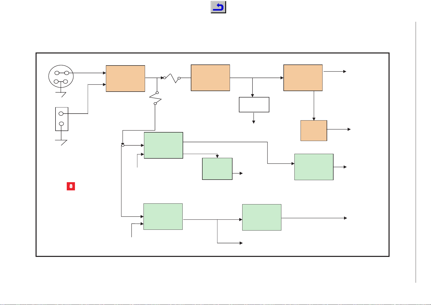
Blockschaltplan Netzteil / Block Diagram Power Supply
J450
12V F450 +2,5V_STBY
(5V) +5V STBY
DC_IN
GND
F451
S450 +3,3V_STBY
12V '33V +1,5V_STBY
12V_AMP
GND
+5V
+8V
STAND_BY +3,3V
+12V PANEL_POWER
PNL_EN +12V_INVERTER
U451
FDS9933A
U454
LM2576
U458
NCP1117
U452
FDS9933N
U457
NCP1117
U453
FDS9933N
U455
LM2576
U456
LM317
VOLTAGE
DOUBLER
U450
NCP117
8
2 - 2
GRUNDIG Service Chassis P6
Page 8

GRUNDIG Service Chassis P6
SCART3_CVBS_IN
QSS_MAIN
AM_SOUND
SCART2_CVBS_IN
QSS_PIP
MA IN_V
PIP_V
SCART3_CVBS_OUT
SCART2_CVBS_OUT
SC1_V_OUT
SCART1_CVBS_IN
+5V
+8V
SDA_5V
SCL_5V
TELETEXT_ CVBS
+33V_IF
Tuner
QSS_MAIN
AM_SOUND
QSS_PIP
MA IN_L
MA IN_R
MSP_RESET
SC1_AUD IO_IN_R
SC1_AUD IO_IN_L
SC3_AUD IO_IN_L
SC3_AUD IO_IN_R
SC2_AUD IO_IN_L
SC2_AUD IO_IN_R
SC3_AUD IO_OUT_L
SC3_AUD IO_OUT_R
SC2_AUD IO_OUT_R
SC2_AUD IO_OUT_L
SC1_OUT_L
SC1_OUT_R
+8V
+5V
SCL_5V
SDA_5V
SWIN
Audio - MSP3410
RXCm
RXCp
RX0m
RX0p
RX1p
RX1m
RX2p
RX2m
GGAI N
GBAIN
GRAIN
GVSY NC
GHSYNC
GGE[7..0]
GBE[7..0]
GFBK
GCLK
ADSCDT
GBO[7..0]
GGO[7..0]
GRO[7..0]
GRE[7..0]
GVS
GHS
GPEN
+5V
+3.3V
SDA
SCL
AD9887_A
GBLKSPL
GCOAST
GHSFOUT
Dual Interface AD9887
RXCm
RXCp
RX0m
RX0p
RX1p
RX1m
RX2p
RX2m
GGAI N
GBAIN
GRAIN
GVSY NC
GHSYNC
+5V
AD9887_A
PC/DVI-D - Input
BL_ON/OFF
DIGITAL DIM_OUT
ANALOG_DIM
STAN D_BY_2
STAN D_BY
A/D_DIM_SELECT
PNL_EN
PANEL_POWER
+5V
+12V_AMP
+8V
+3.3V _STBY
+5V_STBY
+3.3V
+33V_IF
Spannungsversorgung
Power Supply
SCART1_CVBS_IN
SCART2_CVBS_IN
SCART3_CVBS_IN
SC1_V_OUT
SCART2_CVBS_OUT
SCART3_CVBS_OUT
SC1_AUD IO_IN_L
SC1_AUDIO_IN_R
SC3_AUDIO_IN_R
SC3_AUD IO_IN_L
SCART_FB
MA IN_L
MA IN_R
SC2_AUDIO_IN_R
SC1_OUT_R
SC2_AUD IO_IN_L
SC3_AUDIO_OUT_R
SC3_AUDIO_OUT_L
SC2_AUDIO_OUT_R
SC2_AUDIO_OUT_L
SC1_OUT_L
RGB_SWITCH
SCART_RED
SCART_BLUE
SCART_GREEN
LED1_O
LED2_O
IRRCVR
KPD[ 3..0]
SCL_5V
SDA_5V
AM P_SLEEP
+3.3V _STBY
+5V
+5V_STBY
+12V_AMP
MUTE
SWIN
SCART3_CHROMA
Audio - Inputs/Outputs
2
3
1
Schaltplanübersicht / Circuit Diagram Overview
2 - 3
Page 9

GRUNDIG Service Chassis P6
SC2_AUD IO_OUT_L
SC1_OUT_L
SC1_OUT_R
SCART_RED
SCART_GREEN
SCART_BLUE
SCART_FB
MA IN_V
SAA18PIP_VOUT
SA A18MAIN_VOUT
VVHS
VVVS
VVCLK
VY[ 7..0]
VUV[7..0]
VVPEN
FIEL D
SVHS_CIN
SVHS_YIN
+3.3V
+5V
SDA
SCL
SA 7118_3V3D1
VDECOE
SCART3_CHROMA
Video Decoder
VVHS
VVVS
VUV[7..0]
VVCLK
VY[ 7..0]
VVPEN
VR[7..0]
VG[7..0]
VB[ 7..0]
VCLK
VVS
RESETn
VHS 31RAMD[1 5..0]
31MCL K
31CASn
31RASn
31WEn
31RAMA [13..0]
SDA
SCL
PW1231_3V3
PW1231_3V3_SW
PW1231_2V5
PW1231_2V5_D1
PW1231_2V5_D2
PW1231_2V5_1
VPEN
Deinterlacer
MSP_RESET
RGB_SWITCH
D[15..0]
ROMOEn
ADRESS20
ROMWEn
GBE[7..0]
VR[7..0]
GGE[7..0]
VB[7..0]
VG[7..0]
VCLK
VVS
RESETn
VHS
GHS
GPEN
GVS
GCLK
GDECOE
GRE[7..0]
GGO[7..0]
GRO[7..0]
GBO[7..0]
GFBK
ADSCDT
STAND_BY
ANALOG_DIM
A[ 19..1]
RESET
SDA
SCL
DCLK
DGE[7..0]
DHS
DBE[7..0]
DRE[7 ..0]
DVS
DEN
DRO[7 ..0]
DGO[7..0]
POWER_D OWN_LVDS
DBO[7.
.
0]
PANEL_CONTROL
KPD[ 3..0]
IRRCVR
LED2_O
LED1_O
DIGITAL DIM
STAND_BY_2
BL_ON/OFF
A/D_DIM_SELECT
PNL_EN
SDA_5V
SCL_5V
AM P_SLEEP
MUTE
NMI
GCOAST
GBL KSPL
GHSFOUT
FIEL D
VPEN
JTAGRESET
VDECOE
Image Processor
PIP_V
SAA 18PIP_VOUT
SAA 18MAIN_VOUT
SVHS_YIN
SVHS_CIN
GBE[7..0]
GGE[7..0]
GHS
GPEN
GVS
GCLK
TELETEXT_CV BS
SCL
SDA
SA 7118_3V3D1
SCART_FB
SCART_BLUE
SCART_RED
SCART_GREEN
GDECOE
SCART3_CHROMA
Video Decoder PIP
DCLK
POWER_DOWN_LVDS
DRE[7..0]
DGE[7..0]
DBO[7..0]
DGO[7..0]
DRO[7..0]
DEN
DHS
DBE[7..0]
DVS
PANEL_CONTROL
PANEL_POWER
DIGITAL DIM
DIGITAL DIM_OUT
LVDS Transmitter
ROMOEn
D[15..0]
ROMWEn
ADRESS20
A[ 19..1]
RESET
SDA
SCL
NMI
JTAGRESET
Flash Memory
31RAMA [13..0]
31RAMD[1 5..0]
31MCL K
31WEn
31CASn
31RASn
+3.3V
PW1231_3V3_SW
PW1231_2V5
PW1231_3V3
PW1231_2V5_D1
PW1231_2V5_D2
PW1231_2V5_1
SDRAM
SC1_OUT_R
SC2_AUDIO_OUT_L
SC1_OUT_L
_BLUE
MUTE
10
6
13
11
9
5
Schaltplanübersicht / Circuit Diagram Overview
2 - 4
Page 10

GRUNDIG Service Chassis P6
GCKEXT
GRIN
GGIN
GSOGIN
GBIN
GRCLP
GVREF
GBCLP
GGCLP
RTERM
GND12
69
SDA
92
SCL
91
A0
90
A1
89
HSY NC
82
COA ST
84
CKEXT
83
CKINV
94
CLAMP
93
REFIN
125
CTL1
47
CTL2
48
CTL3
49
CTL0
46
VD1
51
GND8
52
SOGIN
108
GND12GND212GND322GND432GND541GND642GND744GND958GND1061GND11
64
VD6
70
NC1
72
GND1374GND1476GND1580G D16
85
VDD11VDD211VDD321VDD431VDD543VDD6
132
VDD7
141
VDD8
151
VD254VD355VD467VD568VD7
96
RX0+
62
RX0-
63
RX1+
59
RX1-
60
RX2+
56
RX2-
57
RXC+
65
RXC-
66
RAIN
119
GAIN
110
BAIN
100
SCANCLK
50
SCANOUT
45
RTERM
53
TESTRST
71
NC2
73
XFILT_OUT
78
VSYNC
81
BCLAMPV
99
RCLAMPV
118
GCL AMPV
109
REFOUT
126
SCANIN
129
RMIDSCV
120
GMIDSCV
111
BMIDSCV
101
A
SCL
GBLKSPL
SDA
GVSYNC
GCOAST
GGAIN
GBAIN
GRA IN
RX0p
RX0m
RX1p
RX1m
RxDDC_SCL
RxDDC_SDA
MDA
MCL
RX2p
RX2m
RXCm
RXCp
GHSYNC
GHSFOUT
AD9887_A
+3V3_AD9887
+
+3V3_AD9887
AD9887_A
AD9887_FILT
560R
*
R3
R47
4K7
4K7
150R
150R
R48
R44
R45
GND
GND
GND
GND
10K
*
R2
100N
*
C25
100N
*
C26
100N
*
C27
100N
*
C28
47N
*
C33
47N
*
C34
47N
*
C35
47N
*
C36
3N9
*
C32
39N
*
C31
3K3
*
R1
100N
*
C2
100N
*
C3
100N
*
C4
100N
*
C5
100N
*
C6
100N
*
C7
100N
*
C8
100N
*
C9
100N
*
C1
100N
*
C18
100N
*
C19
100N
*
C20
100N
*
C21
IN
3
1
OUT
2
ADJ
D-PA CK
U1
GND
22uH
L1
GND
100N
*
C23
+3.3V
+5V
100N
*
C22
0R
*
J2
0R
*
J3
0R
*
J1
0R
*
J4
GND
TP2
TP3
TP4
TP5
TP6
TP7
TP8
TP10
TP11
TP12
TP16
TP17
TP18
TP20
TP22
TP24
TP26
TP28
TP1
TP9
TP13
100U16V
C10
100U16V
C24
AD9887_A
VCC
8
WP
7
SCL
6
SDA
5
A0
1
A1
2
A2
3
GND
4
24LC16
U4
GND
3K3
0603
R46
GND
100N
C249
+3.3V
1
Dual Interface AD9887
2 - 5
Page 11

ADCK
GRE 0
GRE 1
GRE 2
GRE 3
GRE 4
GRE 5
GRE 7
GRE 6
GRO 0
GRO 1
GRO 3
GRO 2
GRO 6
GRO 5
GRO 4
GRO 7
GBE 0
GBE 1
GBE 3
GBE 2
GBE 6
GBE 5
GBE 4
GBE 7
GBO 0
GBO 1
GBO 3
GBO 2
GBO 6
GBO 5
GBO 4
GBO 7
ADR E0
ADR E1
ADR E2
ADR E3
ADR E4
ADR E5
ADR E7
ADR E6
ADR O0
ADR O1
ADR O3
ADR O2
ADR O6
ADR O5
ADR O4
ADR O7
ADG E0
ADG E1
ADG E3
ADG E2
ADG E6
ADG E5
ADG E4
ADG E7
ADG O7
ADG O5
ADG O4
ADG O0
ADG O6
ADG O2
ADG O1
ADG O3
ADB E 0
ADB E 1
ADB E 3
ADB E 2
ADB E 6
ADB E 5
ADB E 4
ADB E 7
ADB O7
ADB O5
ADB O4
ADB O0
ADB O6
ADB O2
ADB O1
ADB O3
GGO0
GGO2
GGO6
GGO1
GGO3
GGO5
GGO4
GGO7
GGE5
GGE2
GGE4
GGE6
GGE7
GGE0
GGE1
GGE3
ADSOG
ADHS
ADVS
ADDE
SOGOUT
140
HSOUT
139
VD6
70
GND13
GND1476GND1580GND1685GND1786GND1895GND1997GND20
102
GND21
103
GND22
106
GND23
112
GND24
113
GND25
116
GND26
121
GND27
122
GND28
128
GND29
130
GND30
131
GND31
133
GND32
142
GND33
152
VD4
VD5
68
PVD487PVD5
88
VD796VD898VD9
104
VD10
105
VD11
107
VD12
114
VD13
115
VD14
117
VD15
123
VD16
124
VD17
127
GREEN_A0
10
GREEN_A1
9
GREEN_A2
8
GREEN_A3
7
GREEN_A4
6
GREEN_A5
5
GREEN_A6
4
GREEN_A7
3
GREEN_B0
20
GREEN_B1
19
GREEN_B2
18
GREEN_B3
17
GREEN_B4
16
GREEN_B5
15
GREEN_B6
14
GREEN_B7
13
BLUE_A 0
30
BLUE_A 1
29
BLUE_A 2
28
BLUE_A 3
27
BLUE_A 4
26
BLUE_A 5
25
BLUE_A 6
24
BLUE_A 7
23
BLUE_B0
40
BLUE_B1
39
BLUE_B2
38
BLUE_B3
37
BLUE_B4
36
BLUE_B5
35
BLUE_B6
34
BLUE_B7
33
RED_A0
150
RED_A1
149
RED_A2
148
RED_A3
147
RED_A4
146
RED_A5
145
RED_A6
144
RED_A7
143
RED_B0
160
RED_B1
159
RED_B2
158
RED_B3
157
RED_B4
156
RED_B5
155
RED_B6
154
RED_B7
153
PVD175PVD277PVD3
79
VSOUT
138
DATACLK
134
DATACLK
135
SYNCDT
136
DE
137
AD9887
U2
GRE[7..0]
GGO[7..0]
GBO[7.0]
GRO[7..0]
GBE[7..0]
GPEN
GCL K
GGE[7..0]
GHS
GFBK
GVS
ADSCDT
AD9887_FILT
3
V3_AD9887
MNR14
RG1
MNR14
RG 2
47R
MNR14
RG13
47R
MNR14
RG12
47R
47R
47R
47R
47R
47R
47R
47R
47R
MNR14
RG11
47R
MNR14
RG10
MNR14
RG9
47R
MNR14
RG8
MNR14
RG7
MNR14
RG 6
MNR14
RG5
MNR14
RG3
MNR14
RG4
47R*
R4
100N
*
C12
100N
*
C13
100N
*
C14
100N
*
C15
100N
*
C16
100N
*
C17
22uH
L2
GND
100N
*
C29
100U16V
C30
1
GRUNDIG Service Chassis P6
Dual Interface AD9887
2 - 6
Page 12

GRUNDIG Service Chassis P6
100R
*
R81
100R
*
R82
SCL_5V
SDA _5V
GND
10U50V
C203
1NF
*
C81
10pF
*
C218
GND
1NF
*
C79
GND
*
C
1NF
*
C77
*
C
2K2
*
R100
2K2
*
R99
GND GND
GND
10U50V
C148
10U50V
C149
100N
*
C54
GND
GND
3.3U
50V
C210
100N
*
C53
GNDGNDGND
220N
*
C113
220N
*
C117
220N
*
C110
220N
*
C114
220N
*
C109
220N
*
C112
1NF
*
C73
1NF
*
C61
1NF
*
C70
1NF
1NF
*
C63
*
C58
1NF
*
C65
1K
R53
1K
R55
1K
R59
1K
R56
1K
R52
1K
R54
GND
GND
GND
GND
GND
GND
SC1_AUDIO_IN_L
SC1_AUDIO_IN_R
10U50V
C146
100N
*
C52
10U50V
C147
100N
*
C55
GND
GND
+5V
QSS_MAIN
56pF
*
C211
56pF
*
C212
56pF
*
C213
GND
GND
GND
1P8
*
C216
1P8
*
C217
GND
GND
1NF
*
C60
1NF
*
C64
1NF
*
C69
1NF
*
C72
GND
GND
GND
GND
AM_SOUND
+5V
+
10uH
3216
L53
10uH
3216
L54
1NF
*
C62
1NF
*
C59
100R
*
R79
100R
*
R80
100R
*
R77
100R
*
R76
GND
GND
220N
*
C115
220N
*
C116
1NF
*
C68
1N
F
1N
F
*
C74
*
C71
1NF
*
C66
GND
GND
GND
GND
1K
R57
1K
R58
QSS_PIP
MSP_RESET
220R
*
R98
100N
*
C56
22uH
0805
L56
2K2
*
R101
BC848B
Q50
GND
+5V
1K
R63
1K
R62
0R
*
J50
J56
J55
GND
GND
P
C_AUDIO_IN_R
PC_AUDIO_IN_L
AV_AUDIO_IN_R
AV_AUDIO_IN_L
ASW_AUDIO_OUT_L
ASW_AUDIO_OUT_R
SC1_MSP
SC1_MSP
SC2_MSP_OU
SC2_MSP_O
GND
I2C_CL1I2C_DA2I2S_CL3I2S_WS4I2S_DA_OUT5I2S_DA_IN16ADR_DA7ADR_WS8ADR_CL9DVSUP10DVSS11I2S_DA_IN212NC13NC14NC15RESETQ16DACA_R
17
DACA_L
18
VREF2
19
DACM_R
20
DACM_L
21
NC
22
DACM_SUB
23
NC
24
SC2_OUT _R
25
SC2_OUT_L
26
VREF1
27
SC1_OUT _R
28
SC1_OUT_L
29
CAPL_A
30
AHVSUP
31
CAPL_M
32
AHVSS
33
AGNDC
34
SC4_IN_L35SC4_IN_R
36
ASG
37
SC3_IN_L38SC3_IN_R
39
ASG
40
SC2_IN_L41SC2_IN_R
42
ASG
43
SC1_IN_L44SC1_IN_R45VFERTOP
46
MONO_IN
47
AVSS
48
AVSUP
49
ANA_IN1+
50
ANA_IN-
51
ANA_IN2+
52
TESTEN
53
XTAL_IN
54
XTAL_OUT
55
TP
56
AUD_CL _OUT
57
NC
58
NC
59
D_CTR_I/O_1
60
D_CTR_I/O_0
61
ADR_SEL
62
STBYQ
63
NC
64
MSP3410
U51
TP50
TP52
TP56
TP59
TP51
TP53
TP55
TP58
TP64
TP67
TP70
TP76
TP78
TP73
TP74
T
P75
TP80
T
TP88
QUARZO-VERT Y50
SWIN
10R
*
R26
23
22
£
Audio - MSP3410
2 - 7
Page 13

GRUNDIG Service Chassis P6
1NF
*
C80
1NF
*
C78
GND
GND
MAIN_L
MAIN_R
*
C99
*
C10 0
G
1NF
*
C82
1NF
*
C76
GND
GND
47U50V
C214
47U50V
C215
SC1_OUT_L
SC1_OUT_R
+8V
+5V_HP
BC848C
Q54
BC848C
Q51
BC848C
Q53
BC848C
Q52
1K
R61
1K
R69
1K
R64
1K
R60
100R
*
R78
100R
*
R83
*
R93
*
R95
GND
GND
GND
GND GND
GND
GND
GND
GND
GND
GND
GND
680R
R104
680R
*
R102
150P
*
C101
150P
*
C102
150P
*
C103
150P
*
C104
4N7
*
C134
4N7
*
C132
47U50V
C106
47U50V
C105
C107
C108
680R
*
R105
680R
*
R103
22uH
L51
22uH
L50
0R
*
J52
GND
220N
*
C119
220N
*
C120
220N
*
C1
21
220N
*
C122
220N
*
C123
220N
*
C124
220N
*
C125
220N
*
C126
220N
*
C128
1NF
*
C83
1NF
*
C86
1NF
*
C87
1NF
*
C91
1NF
*
C92
1NF
*
C94
1NF
*
C95
1NF
*
C98
1K
R65
1K
R66
1K
R67
1K
R68
1K
R70
1K
R71
1K
R72
1K
R73
SC3_AUDIO_I N_L
SC2_AUDIO_I N_L
SC3_AUD IO_IN_R
DMC R
SC2_AUDIO_I N_R
GND
GND
GND
GND
GND
GND
GND
GND
GND
220N
*
C127
0R
J51
RCA VIDEO
J56
J55
GND
GND
PHONEJACK3-PC
J57
GND
R
PC_AUDIO_IN
L
AV_AUDIO_IN
HP_R
MSP_8V
MSP_8V
MSP_8V
MSP_8V
MSP_8V
HP_L
HP_R
TP38
TP63
TP65
TP66
TP61
TP91
TP77
TP72
TP68
T
P89
TP88
TP57
TP81
TP84
TP86
TP87
TP92
TP98
TP96
TP95
TP100
TP102
TP101
TP103
100U16V
C225
GND
1NF
*
C265
1K
R115
GND
22
22
24
™
≤
Audio - MSP3410
2 - 8
Page 14

GRUNDIG Service Chassis P6
02.11.2004
GND
GND
1
2
3
S50
GND
GND
OUTA
1
INA(NEG)
2
INA(POS)
3
VSS
4
INB(POS)
5
INB(NEG)
6
OUTB
7
VDD
8
SO8
TDA1308
U50
220N
*
C111
220N
*
C118
4K7
*
R74
4K7
*
R75
2N2
*
C204
2N2
*
C206
2N2
*
C207
2N2
*
C205
GND
GND
GND
100N
*
C51
GND
10K
*
R50
10K
*
R51
10U50V
C145
GND GND
22K
*
R97
22K
*
R96
1N5
*
C129
1N5
*
C130
1NF
*
C67
1NF
*
C75
100U16V
C208
100U16V
C209
GND
GND
10uH
3216
L52
10U50V
C144
100N
*
C50
GND GND
SCL
27
ADDR
26
L1
4
L2
5
L3
6
L4
9
L5
10
R1
25
R2
24
R3
23
R4
20
R5
19
LOUT1
11
LOUT2
13
LOUT3
15
LOUT4
17
ROUT1
12
ROUT2
14
ROUT3
16
ROUT4
18
SDA
28
C
2
NC
22
NC
21
NC
7
NC
8
VS
3
GND
1
TEA6420
U52
0R
*
J52
22U50V
C143
22U50V
C140
22U50V
C138
22U50V
C141
22U50V
C142
22U50V
C135
22U50V
C136
22U50V
C137
22U50V
C139
100R
*
R91
100R
*
R90
100R
*
R89
100R
*
R88
100R
*
R87
100R
*
R86
100R
*
R85
100R
*
R84
1NF
*
C97
1NF
*
C96
1NF
*
C93
1NF
*
C89
1NF
*
C90
1NF
*
C88
1NF
*
C84
1NF
*
C85
GND
GND
GND
GND
GND
GND
GND
GND
GND
SC2_AUD IO_OUT_L
SC3_AUD IO_OUT_L
SC2_AUD IO_OUT_R
SC3_AUD IO_OUT_R
+8V
100N
*
C57
GND
100R
*
R92
100R
*
R94
SDA_5V
SCL_5V
*
0R
*
J51
RCA VIDEO
J54
RCA VIDEO
J53
GND
GND
H
P_L
ASW_AUDIO_OUT_L
AV_AUDIO_OUT_L
AV_AUDIO_OUT_L
ASW_AUDIO_OUT_R
AV_AUDIO_OUT_R
AV_AUDIO_OUT_R
10uH
3216
L55
+5V_HP +5V
TP69
TP71
TP60
TP54
TP57
TP79
TP82
TP83
TP85
TP90
TP93
TP94
TP97
TP99
Audio - MSP3410
2 - 9
Page 15

GRUNDIG Service Chassis P6
3
1
1
3
3
5
5
7
7
9
9
11
11
13
13
15
15
17
17
19
19
2
2
4
4
6
6
8
8
10
10
12
12
14
14
16
16
18
18
20
20
21
21
SCART 1
P151
1NF
*
C171
1NF
*
C172
330R
*
R172
330R
*
R173
SC1_OUT_R
SC1_OUT_L
1NF
*
C173
1NF
*
C174
SC1_AUDI O_IN_R
SC1_AUDIO_IN_L
75R
R198
75R
*
R199
75R
*
R200
75R
*
R201
100R
*
R190
100pF
*
C194
100pF
*
C193
100pF
*
C192
100pF
*
C196
SCART1_CVBS_IN
SC1_V_OUT
330R
*
R170
330R
*
R171
1
1
3
3
5
5
7
7
9
9
11
11
13
13
15
15
17
17
19
19
2
2
4
4
6
6
8
8
10
10
12
12
14
14
16
16
18
18
20
20
21
21
SCART 2
P152
1NF
*
C177
1NF
*
C178
330R
*
R174
330R
*
R175
SC2_AUDIO_OUT_R
SC2_AUDIO_OUT_L
1NF
*
C179
1NF
*
C180
SC2_AUDIO_IN_R
SC2_AUDI O_IN_L
75R
75R
75R
*
R203*R204*R205
75R
*
R206
100R
*
R195
0R
0R
J16
J17
100pF
*
C200
100pF
*
C199
100pF
*
C198
100pF
*
C202
SCART2_CVBS_IN
SCART2_CVBS_OUT
A1
2
A2
5
A3
11
A4
14
B1
3
B2
6
B3
10
B413GND
8
VCC
16
OE
15
A/B
1
Y1
4
Y2
7
Y3
9
Y4
12
TSSOP16U150
GND
GND GND
GND
*
R183*R182
3K9
3K9
3K9
*
R181
15K
*
R179
15K
*
R178
15K
*
R177
GND
SCL 5V
SDA _5V
100R
*
R184
100R
*
R185
3K9
*
R180
100N
*
C151
100U16V
C164
GND
22uH
L150
GND
4K7
*
R169
GND
GND
GND
100U16V
C163
100N
C1
150p
C248
50
GND
SCART_RED
SCART GREEN
SCART_BLUE
SCART_FB
RxD
TxD
RGB_SWITCH
1K
R161
SC3_AUDIO_OUT_R
SC3_AUDIO_OUT_L
GND
MAIN_L
MAIN_R
MUTE
GND
GND
GND
GND
150P
*
C189
150P
*
C188
SCART1 BLU E
SCART1 GREEN
SCART1 RED
SCART1_FB
SC1 PN8
SCART2_BLUE
SCART2_GREEN
SCART2_RED
SC
only PCB version 8
2_PIN8
SCART2 FB
SCART1_RED
SCART1 GREEN
SCART1_BLUE
SCART1 FB
SCART2 RED
SCART2 GREEN
SCART2 BLUE
SCART2 FB
SC1_PIN8
SC2 PIN8
SC3_PIN8
+12V_AMP
+5V
+5VAIN1
2
A0
5
OSC
11
VREF
14
AIN2
3
A1
6
SCL
10
AGND13VSS
8
VCC
16
AOUT
15
AIN0
1
AIN3
4
A2
7
SDA
9
EXT
12
SO16W
U151
-INV1
1
SGND
2
SVRR
3
OUT1
4
PGND
5
OUT2
6
VP
7
M/SS
8
-INV2
9
GND
10
GND
11
GND
12
GND
13
GND
14
GND
15
GND
16
GND
17
GND
18
DIP18
U101
1
2
3
4
MOLCON4
S104
220N
*
C261
220N
*
C262
100N
*
C260
10K
*
R144
10K
*
R139
10K
*
R143
47U50V
C263
1000U16V
C152
1000U16V
C153
1000U16V
C154
47K
*
R11
27K
*
R158
SOT23
BC848B
Q105
47U50V
C264
GND
GND
GND
GND
GND
GND
MU
+1
1uH
R1/4W-P400
L1004
TP506
TP507
TP508
TP509
TP510
TP511
TP512
TP513
TP514
TP515
TP516
TP517
TP518
TP519
TP520
TP521
TP522
TP524
TP523
TP525
TP526
TP527
TP529
TP528
TP530
GND
*
C131
*
C133
GND
D13
1N4148
M
AIN_L
MAIN_R
M
AIN_L
MAIN R
+1
75R
*
R29
220N
*
C40
*
C191
GND
SCART3_CHROMA
680R
680R
R108
R109
+3.3V
BC848B
Q4
GND
Audio - Input/Output
2 - 10
Page 16

GRUNDIG Service Chassis P6
3
02.11.2004
1
1
3
3
5
5
7
7
9
9
11
11
13
13
15
15
17
17
19
19
2
2
4
4
6
6
8
8
10
10
12
12
14
14
16
16
18
18
20
20
21
21
SCART 3
P150
1NF
*
C165
1NF
*
C166
330R
*
R170
330R
*
R171
1NF
*
C167
1NF
*
C168
SC3_AUDIO_IN_R
SC3_AUDIO_IN_L
SCART3_CVBS_IN
SCART3_CVBS_OUT
IRRCVR
LED1 O
LED2_O
10K
*
R153
10K
*
R154
10K
*
R155
10K
*
R156
0R
0R
J16
J17
RxD
TxD
GND
GND
GND
1
2
3
4
5
6
7
8
9
10
MOLCON10
S150
150P
*
C187
+5V_STBY
+3.3V_STBY
KPD3
KPD1
KPD0
KPD2
KPD[3..0]
SC3_PN8
+5V_STBY
10K
*
R157
100K
*
R176
4K7
*
R168
+3.3V_STBY
BC848B
Q150
GND
MUTE
GND
GND
+12V_AMP
10K
*
R40
10K
R41
10K
*
R42
10K
*
R43
1
2
3
4
5
6
7
JP150
TP500
TP41
TP501
TP502
TP503
TP504
TP505
T
P531
TP532
TP537
TP536
TP535
TP534
TP533
1
2
41792-2
S1050
PGND1PGND
2
VDD3VDD
4
C1N
5
C1P
6
CHOLD
7
REG
9
AGND
10
IN+
11
IN-
12
SS
13
SHDN
14
G1
15
G2
16
NC
17
FS1
18
FS2
19
NC
20
VDD21VDD
22
PGND23PGND
24
NC25NC
26
OUT-
27
OUT-
28
OUT+
29
OUT+
30
NC31NC
32
NC
8
MAX9703
U1050
100N
*
C1052
100N
*
C1053
1U50V
C1059
100N
*
C1054
470N
63V
C1056
SWIN
470N
63V
C1058
33U35V
C1050
33U35V
C1051
470N
63V
C1057
22uH
L1051
100pF
*
C1055
10K
*
R1050
BC848B
Q1050
4K7
*
R1051
MUTE
TP1050
OPTI ON
TP105 1
GND
GND
GNDGND
GND
GND
GND
GND
GND GND
GND
GND
1NF K 50V
*
C1019
GND
123
4
SPEA KER
SST
250G2-V04
S2
GND
GND
GND
GND
GND
GND
GND
GND
GND
GND
GND
GND
OUTP1
OUTM1
OUTM2
OUTP2
OUTP1
OUTM1
OUTM2
OUTP2
+12V_AMP
+5VGEN
1
DCAP2
2
DCAP1
3
V5D
4
AGND1
5
REF
6
OVERLOADB
7
AGND2
8
V5A
9
VP1
10
IN1
11
MUTE
12
NC
13
VP2
14
IN2
15
BIASCAP
16
AGND3
17
SLEEP18FAULT
19
PGND2
20
NC
21
DGND
22
NC
23
OUTP2
24
VDD2
25
VDD2
26
OUTM2
27
OUTM1
28
VDD1
29
VDD1
30
OUTP1
31
NC
32
VDDA
33
NC
34
PGND1
35
CPUMP
36
TA2024
U3
100MHz 4A
100MHz Bead
L7
GND
100MHz 4A
100MHz Bead
L9
GND
100MHz 4A
100MHz Bead
L21
GND
8K2
8K2 %1
R19
22K
*
R20
*
C131
22K
*
R22
*
C133
GND
0R
*
J6
*
J8
100N
*
C46
10uH
L23
10R
*
R25
10R
*
R28
470N 63V
C156
470N 63V
C175
CAP2.2U10V
C221
GND
VDD
150U25V
C220
100N
*
C45
150U25V
C219
VDD
VDD
VDD
VDD
VDD
D Schottky
D5
D Schottky
D3
D Schottky
D4
D Schottky
D6
GND
GND
GND
GND
1NF K 50V
*
C157
1NF K 5 V
*
C158
1NF K 50V
*
C160
1NF K 50V
C159
100N
*
C44
22K
*
R21
22K
*
R23
100N
*
C47
100N
*
C48
1M
*
R24
1NF K 50V
*
C161
470N 63V
C176
470N 63V
C170
470N 63V
C169
470N 63V
C162
10uH
L24
10uH
L22
10uH
L25
100N
*
C155
100N
*
C49
2.2U50V
C222
MUTE_1
AIN_L
AIN_R
1U 63V
C201
1U 63V
C197
MUTE 1
+12V_AMP
+12V_AMP
+5V
75R
*
R29
1
1uH
L1050
26 25
∞
§
Audio - Input/Output
2 - 11
Page 17

PC/DVI-D - Input
GBLUEF
GREDF
GGREENF
CSCL
CSDA
D259
BAV99
D254
*L25 1
BAV99
D256
NC1
1
NC2
2
NC3
3
GND
4
SDA
5
SCL
6
VCLK
7
VCC
8
SO8
U251
NC1
1
NC2
2
NC3
3
GND
4
SDA
5
SCL
6
VCLK
7
VCC
8
SO8
U250
1
2
3
4
5
6
7
8
9
10
11
12
13
14
15
16 17
DB15HF
P250
*L252
BAV99
D257
BAV99
D258
D260
BAV99
D252
BAV99
D255
BAV99
D253
BAV99
D251
*L25 0
BAV99
D250
RX2p
RX2m
RXCm
RX1p
RX0m
RX1m
RX0p
RXCp
GHSYNC
GBA IN
GGAIN
GRAI N
GVSYNC
VCC_DVI
VCC_DVI
VCC_PC
VCC_PC
AD9887_A
VCC_PC
GND GND
GND
GND
GND
GND
GND
GND GND GND
GND GND GND GND GND GND
GND
GND
GND
3K3
*
R254
3K3
*
R255
3K3
*
R253
75R
*
R257
75R
*
R258
75R
*
R259
2K
*
R260
RX2-
1
RX2+
2
GND
3
RX4-
4
RX4+
5
SCL
6
SDA
7
VS
8
RX1-
9
RX1+
10
GND
11
RX3-
12
RX3+
13
5V
14
GND
15
HP
16
RX0-
17
RX0+
18
GND
19
RX5-
20
RX5+
21
GND
22
RXC+
23
RXC-
24
Shell
31
Shell
32
RED C1
25
GRN C2
26
BLU C3
27
HS C4
28
GND C5
29
GND C5
30
74320-1000
CN25 0
* 03
J251
GND
3K3
*
R250
3K3
*
R251
3K3
*
R252
100N
*
C250
100N
*
C251
12P
*
C254
12P
*
C253
12P
*
C252
RAIN
GAIN
BAIN
RAIN
GAIN
BAIN
HSYNC
HSYNC
GVSYNC
VSYNC
VSYNC
*
J252
GVSYNC
GVSYNC
0R
*
J250
10K
*
R256
TP35
TP36
TP252
TP253
0R
*
J253
0R
*
J254
0R
*
J255
0R
*
J256
+5V
+5V
TP267
G1
1
S2
2
G2
3
D2
4
S1
5
D1
6
NDC7 002 N
U5
4K7
R38
4K7
R39
RxDDC_SDA
RxDDC_SCL
+3.3V_STBY
DDC_SDA
DDC_SCL
GRUNDIG Service Chassis P6
2 - 12
Page 18

GID2
GHD6
GID7
GID0
GHD5
GIGPV
GID6
GIGPH
GHD3
GHD1
GHD4
GIDQ
GHD0
GICLK
GXTAL
GID1
GID4
GXTALI
GHD2
GHD7
GID5
GID3
GBE4
GGE2
GBE3
GBE6
GGE7
GGE1
GGE0
GGE6
GBE5
GGE5
GBE2
GGE3
GBE7
GBE0
GBE1
GGE4
GLLC
GLLC2
GRTS0
(27Mhz)
(13.5Mhz)
AI2D
H1
AI1D
K3
TRST
C6
TCK
B6
TMS
D6
TDO
A5
TDI
B5
XTOUT
A2
XTAL
A3
XTALI
B4
AI24
J3
AI21
G4
AI22
G3
AI23
H2
AI11
J2
AI12
K1
AOUT
M1
CE
N4
LLC
P4
LLC2
N5
RESO
P5
SCL
N9
SDA
P10
RTS0
M10
RTS1
N10
RTCO
L10
AMCLK
P11
ASCLK
N11
ALRCLK
P12
AMX CLK
M12
ITRDY
N12
ITRI
L12
ICLK
M14
IDQ
L13
IGP0
L14
IGP1
K13
IGPV
K14
IGPH
K12
IPD0
G14
IPD1
G12
IPD2
H11
IPD3
H14
IPD4
H13
IPD5
J14
IPD6
J13
IPD7
K11
HPD0
D14
HPD1
E11
HPD2
E13
HPD3
E12
HPD4
E14
HPD5
F13
HPD6
F14
HPD7
G13
TEST1
D13
TEST2
C14
TEST3
A13
TEST4
B12
TEST5
A12
XPD0
A8
XPD1
B8
XPD2
A9
XPD3
B9
XPD4
A10
XPD5
B10
XPD6
A11
XPD7
C11
XTRI
B11
XRDY
A6
XDQ
B7
XRH
C7
XRV
D8
XCLK
A7
TEST0
P13
VXD D
B3
VDDE1C5VDDE2C9VDDE3
D12
VDDE4
H12
VDDE5M4VDDE6M8VDDE7
M11
VDDI 1C8VDDI 2
C10
VDDI 3
F12
VDDI 4
J12
VDDI 5M5VDDI 6
M9
VDDA0M3VDDA1K4VDDA2H4VDDA3F4VDDA4
D4
VDDA1 AL1VDDA2 AJ1VDDA3 AG2VDDA4 A
E2
VSSA0M2VSSA1J4VSSA2H3VSSA3E4VXSSA4VSSE1D5VSSE2D9VSSE3
D11
VSSE4
G11
VSSE5L4VSSE6L8VSSE7
L11
VSSI1D7VSSI2
D10
VSSI3
F11
VSSI4
J11
VSSI5L5VSSI6
L9
AI13
K2
AI14
L3
AI31
E3
AI32
F2
AI33
F3
AI34
G1
AI3D
F1
AI41
B1
AI42
D2
AI43
D1
AI44
E1
AI4D
D3
VSSA4
C1
AGNDA
L2
RES1
B2
RES2
B13
RES3
B14
RES4
C3
RES5
C4
RES6
C12
RES7
C13
ADP0
N8
ADP1
P8
ADP2
M7
ADP3
L7
ADP4
P7
ADP5
N7
ADP6
L6
ADP7
M6
ADP8
P6
RES8
N1
RES9
N2
RES10
N3
RES11
N13
RES12
N14
RES13
P2
FSW
M13
CLKEXT
N6
EXMCLR
P3
INT_A
P9
AGND
C2
SAA7 118 ( G)
U300
TP316
TP317
TP31 8
GCLK
GPEN
GHS
GVS
GBE[7..0]
GGE[7..0]
SA7118_A2
SA7118_3V3D2
Y- DATA
UV-DATA
56R
56R
*
R306
*
R307
GNDGND
47N
*
C324
47N
*
C325
47N
*
C323
47N
*
C321
47N
*
C322
47N
*
C320
47N
*
C316
47N
*
C315
47N
*
C318
47N
*
C313
47N
*
C317
GND
GND
GND GND GND GND GND GND GND GND GND
GND GND GND GND GND GND
47R
MNR14
RG301
47R
MNR14
RG302
47R
MNR14
RG303
47R
MNR14
RG304
47U50V
C328
47U50V
C329
100N
*
C305
100N
*
C306
100N
*
C307
100N
*
C308
100N
*
C309
100N
*
C310
100N
*
C311
100N
*
C312
100N
*
C300
100N
*
C301
100N
*
C302
100N
*
C303
100N
*
C304
SA7118_3V3D2
GND
GND
GND
PIP_V
SVHS_CIN
SVHS_YIN
SAA18MAI N_VOUT
*
18R
R304
*
18R
R305
SDA
SCL
100R
*
R302
100R
*
R303
GND
SCART_FB
22uH
22uH
L300
22uH
22uH
L301
SA7118_3V3D1
0R
*
J306
SA7118_A2
SCART_RED
SCART_GREEN
SCART_BLUE
SAA18PIP_VOUT
+3.3V
0R
*
J308
4K7
*
R301
GND
+3.3V
GND
18P
*
C327
18P
*
C326
0R
*
J300
0R
*
J302
0R
*
J304
0R
*
J305
0R
*
J3
0R
*
J301
0R
*
J307
TXT_FB
TXT_R
TXT B
TXT_G
+3.3V
TXT R
TXT_G
TXT_B
TXT_FB
SDA
GND
SDA
SCL
SCL
+3.3V
TELETEXT_CVBS
GXRH
GXRV
GXRV
GXRH
GND
1 2
3 4
5 6
7 8
9 10
11 12
MHDR2X6
JP300
GND
GND
47R
MNR14
RG300
10K
R300
GDECOE
TP300
TP303
TP304
TP306
TP310
TP313
TP312
TP314
TP315
TP320
TP319
TP321
47N
*
C314
47N
*
C319
TELETEXT_CVBS
SCART3_CHROMA
QUARZO-VERT
Y300
Video Decoder PIP
GRUNDIG Service Chassis P6
2 - 13
Page 19

GRUNDIG Service Chassis P6
DBO3
DGO0
DBE2
DBO4
DRO2
DGE7
DRE4
DRE5
DRO0
DBO6
DGE4
DBO1
DGO3
DRE2
DBO7
DRO3
DRE6
DGE0
DGO2
DGE5
DRO1
DRE7
DGE2
DBE3
DRO4
DRO6
DGE6
DBO2
DBE1
DRE0
DGE3
DBO5
DBE7
DGO1
DGE1
DRE3
DBE4
DRE1
DBO0
DRO5
DGO5
DBE6
DBE5
DGO4
DRO7
DBE0
TXIN0
51
TXIN1
52
TXIN2
54
TXIN3
55
TXIN4
56
TXIN5
2
TXIN6
3
TXIN7
4
TXIN8
6
TXIN9
7
TXIN10
8
TXIN11
10
TXIN12
11
TXIN13
12
TXIN14
14
TXIN15
15
TXIN16
16
TXIN17
18
TXIN18
19
TXIN19
20
TXIN20
22
TXIN21
23
TXIN22
24
TXIN23
25
TXIN24
27
TXIN25
28
TXIN26
30
TXIN27
50
TXOUT0
47
TXOUT1
45
TXOUT2
41
TXOUT3
37
TXCOUT
39
TXOUT0
48
TXOUT1
46
TXOUT2
42
TXOUT3
38
TXCOUT
40
CLKIN
31
PWRDN
32
R_F
17
VCC11VCC29VCC3
26
PVCC
34
OVCC
44
GND15GND213GND321GND429GND5
53
PGND133PGND2
35
OGND136OGND243OGND3
49
DS90C385
U350
DCLK
DGE[7..0]
DBO[7..0]
DBE[7..0]
DVS
DRE[7..0]
DRO[7..0]
DHS
DEN
POWER_DOWN_LVDS
GND
TXE_0-
TXE_0+
TXE_1-
TXE_1+
TXE_2-
TXE_2+
TXE_3-
TXE_3+
TXCLKE-
TXCLKE+
0R
*
J354
4K7
*
R353
+3.3V
100N
*
C350
100N
*
C351
100N
*
C352
100N
*
C353
GND
DGO[7..0]
5
6
7
B
84
SO8
U351B
2
3
84
A
SO
U3
GND
GND
+12V_AMP
1U50V
C356
GND
DIGITAL DIM
GND
+12V_AM
*
C
10K
*
R352
*
C355
10K
*
R351
4K7
*
R354
TP412
T
P371
TP374
TP377
GND
+3.3V
DHS
DVS
DEN
1uH
L1005
100U16V
C43
TXIN0
51
TXIN1
52
TXIN2
54
TXIN3
55
TXIN4
56
TXIN5
2
TXIN6
3
TXIN7
4
TXIN8
6
TXIN9
7
TXIN10
8
TXIN11
10
TXIN12
11
TXIN13
12
TXIN14
14
TXIN15
15
TXIN16
16
TXIN17
18
TXIN18
19
TXIN19
20
TXIN20
22
TXIN21
23
TXIN22
24
TXIN23
25
TXIN24
27
TXIN25
28
TXIN26
30
TXIN27
50
CLKIN
31
PWRDN
32
R_F
17
VCC11VCC29VCC
26
GND15GND213GND321G D
29
DS9
U3
GND
0R
*
J7
4K7
*
R18
+3.3V
100N
*
C181
GND
+3.3V
POWER_DOWN_LVDS
DHS
DVS
DEN
1uH
L20
DGO6
DGO7
DCLK
DCLK
6
LVDS Transmitter
2 - 14
Page 20

123
45678
9
10111213141516
1718192021
22
23242526272829
30
S350
TXE 0-
TXE_0+
TXE_1-
TXE_1+
TXE_2-
TXE_2+
TXCLKE-
TXCLKE+
TXE 3-
TXE_3+
GND GND GND
PANEL_CONTROL
*
J352
*
J350
0R
0R
0R
0R
0R
0R
0R
*
J351
DHS
DVS
DEN
*
J353
GND
7
1
84
A
SO8
U351A
1U50V
C356
DIGITAL DIM_OUT
GND
100N
*
C354
GND
TP409
TP352
TP353
TP354
TP355
TP356
TP357
TP358
TP359
TP363
TP366
TP351
4K7
*
R17
+3.3V
1 2
3 4
5 6
7 8
9 10
11 12
13 14
15 16
17 18
19 20
MHDR2X10
JP1
TXOUT0
47
TXOUT1
45
TXOUT2
41
TXOUT3
37
TXCOUT
39
TXOUT0
48
TXOUT1
46
TXOUT2
42
TXOUT3
38
TXCOUT
40
VCC11VCC29VCC3
26
PVCC
34
OVCC
44
G D1
GND213GND321GND429GND5
53
PGND133PGND2
35
OGND136OGND243OGND3
49
DS90C385
U352
TXO_0-
TXO_0+
TXO_1-
TXO_1+
TXO_2-
TXO_2+
TXO_3-
TXO_3+
TXCLKO-
TXCLKO+
100N
*
C181
100N*100N*100N
*
C184
C183
C182
GND
TP14
TP15
100U16V
C185
TXO_0TXO_0+
TXO_2TXO_2+
TXO_3TXO_3+
TXCLKOTXCLKO+
GND
PANEL_POWER
TXO_1TXO_1+
*
J12
*
J13
GND
TP19
TP21
TP23
TP25
TP27
TP37
TP39
TP40
*
J9
13 12
14 15
11 10
9 8
16 17
#
@
$
%
!
0
9
8
^
&
6
GRUNDIG Service Chassis P6
LVDS Transmitter
2 - 15
Page 21

GRUNDIG Service Chassis P6
I RP n
D8
D0
D7
D9D1
D4
D3
D10D2
D3
D12
D6
D14
D10
D15
D11
D0
D4
D14
D13
D7
D5
D1
D6
D9
D2
D13
D11
D8
D5
D12
D15
TLCCT
RSTI Nn
A8
A2 A3
A15
A14
A8
A15
A19
A9
A9
A12
A16
A14
A12
A4
A17
A18
A5
A13
A11
A7
A5
A13
A10
A4
A16
A1
A3
A6
A18
A2
A17
A19
A6
A1
A10
A11
A7
GND
4
RESET
5
RESIN
2
VDD
8
RESET
6
CONTROL
1
CT
3
SENSE
7
SO8
U402
1
1
2
2
3
3
4
4
5
5
6
6
7
7
8
8
9910
10
111112
12
131314
14
151516
16
171718
18
191920
20
212122
22
232324
24
252526
26
272728
28
292930
30
313132
32
333334
34
353536
36
373738
38
393940
40
414142
42
434344
44
454546
46
474748
48
494950
50
TML125- 02-G -D -SM
JP4 01
VCC
37
VPP
13
GND1
46
GND2
27
D1
29
D9
30
D2
31
D10
32
D3
33
D11
34
D4
35
D12
36
D5
38
D13
39
D6
40
D14
41
D7
42
D15
43
D8
44
D16
45
A15
1
A14
2
A13
3
A12
4
A11
5
A10
6
A9
7
A8
8
A17
17
A7
18
A6
19
A5
20
A4
21
A3
22
A2
23
A1
24
A0
25
A16
48
CE
26
OE
28
WE
11
RP
12
WP
14
BYTE
47
A18
16
A19
9
24LV16 0
U400
SDA
5
SCL6VCC
8
GND
4
NC0
1
NC1
2
NC2
3
WP
7
SO8
U401
D[15..0]
SDA
RESET
SCL
ROMW En
ROMOEn
A[19..1]
Debugger H ead er
0R
*
J401
GND
GND
GND GND
100N
*
C400
GND
100R
*
R404
+3.3V_STBY
+3.3V_STBY
100N
*
C402
RESET
100N
*
C401
1 2
3 4
5 6
7 8
9 10
MHDR2X5
JP400
ADRESS20
GND
GND GND
3K3
*
R400
3K3
*
R401
0R
*
J400
+3.3V_STBY
+3.3V_STBY
+3.3V_STBY
+3.3V_STBY
+3.3V_STBY
3K3
*
R402
3K3
*
R403
+3 3V_STBY
0R
*
J403
GND
+3.3V_STBY
0R
*
J402
+3.3V_STBY
ROMOEn
ROMW En
ROMOEn
ROMW En
NMI
+3.3V_STBY
18P
*
C403
GND
GND
18P
*
C404
GND
GND GND
4K7
*
R405
+3.3V_STBY
TP153
TP1 54
TP155
TP156
TP157
TP158
TP159
TP160
TP161
TP162
TP163
TP164
TP165
TP166
TP167
TP168
TP169
TP170
TP171
TP172
TP173
TP174
TP175
TP176
TP177
TP178
TP179
TP180
TP181
TP182
TP183
TP184
TP188
TP189
TP191
TP192
TP193
TP1 94
TP195
TP196
TP197
TP198
TP199
TP200
GND
TP201
TP202
TP204
TP203
0R
*
J1000
TP33
TP34
Flash Memory
2 - 16
Page 22

GRUNDIG Service Chassis P6
8
FUSE_MXT
F450
S1
1
G1
2
S2
3
G2
4
D1
8
D1
7
D2
6
D2
5
SO8
U452
S1
1
G1
2
S2
3
G2
4
D1
8
D1
7
D2
6
D2
5
SO8
U453
1
2
S450
*
C
*
03
GND GND
100U50V
C487
+5V _STBY
10K
*
R453
10K
*
R454
GND
STAND_BY
SOT23
BC848B
Q450
100U16V
C480
100N
*
C452
GND GND
+5V
OUT
2
VCC
3
1
GND
D-PA CK
U458
+5V _STBY
100U16V
C483
100U16V
C484
10U50V
C479
100N
*
C461
100N
*
C4
60
GND
+3.3V_STBY
+12V
1N4148
D450
+2.5V_STBY
10K
*
R455
10K
*
R456
BC848B
Q451
GND
PNL_EN
100N
*
C466
GND
GN
D
GND
100N
*
C455
100N
*
C468
GND
GND
S1
1
G1
2
S2
3
G2
4
D1
8
D1
7
D2
6
D2
5
SO8
U451
GND
10K
*
R452
10N
C474
GND
+12
+12
2V
1
2
3
4
5
6
7
8
9
10
MHDR1X10
JP451
GND
+12
STAND_BY_2
GND
100N
*
C456
100U50V
C475
GND GND
+12V_AMP
+12V_AMP
100N
*
C459
TP473
TP480
TP469
TP464
TP466
TP463
TP470
TP467
TP462
TP468
CON-POWER4
J450
10K
R466
1000U50V
C1014
GND
FUSE_MXT
F451
IN
8
COMPR
3
OUT
1
NC
2
NC
5
NC
6
NC
7
GND
4
LM3411AN5.0U459
C469
C470
47U50V
47U50V
47U50V
C471
GND
100N
*
C465
GND
GND
GND
1N5820-REV
D453
GND
100N
*
C467
L452
3K3
*
R451
GND
100U50V
C476
GND
+12V_OUT
+12V
1K
R450
1K
R465
1K
R1007
1K
R1006
1K
R1008
1K
R1009
+12V_OUT
1K
R1013
1K
R1012
1K
R1014
1K
R1015
+12V
+12V_OUT
1000U50V
C41
100U
50V
C42
100uH
L14
100uH
L15
100uH
L17
100uH
L19
L8
L10
L11
100uH
100uH
100uH
100uH
L13
1
2
3
4
5
6
7
MHDR1X7
JP450
10uH
L4
+3.3V
100uHL26
100uHL27
100uHL28
L12
+12V_AMP
1K
R1016
+3.3V_STBY
+5V _STBY
Spannungsversorgung / Power Supply
2 - 17
Page 23

GRUNDIG Service Chassis P6
02.11.2004
VIN
1
ON/OFF
5
VOUT
2
GND
3
FBK
4
TO263U454
100N
*
C450
100N
C451
1N5820-REV
D451
L450
GND
GND
GND +5V _STBY
+
5V
OUT
2
VCC
3
1
GND
D-PA CK
U457
100U16V
C485
100U16V
C486
100U16V
C481
100U16V
C482
100N
*
C464
100N
*
C463
100N
*
C457
100N
*
C458
GND
+
3.3V
+1.5V_STBY
+5V
GND
*
GND
GN
D
*
GN
D
1K
R459
1K
R460
GND
GND
VIN
1
ON/OFF
5
VOUT
2
GND
3
FBK
4
TO263U455
100N
*
C462
1N5820-REV
D452
L451
GND
PANEL_POWER
1
2
3
4
5
6
7
8
9
10
11
12
MHDR1X12
JP452
1
2
3
4
5
6
7
8
9
10
MHDR1X10
JP453
+12V_INVERTER
+12V_INVERTER
GND
GND
D
ANALOG_DIM
DIGITAL DIM_OUT
A/D_DIM_SELECT
BL_ON/OFF
220N
C472
220N
C473
+12V_INVER
TER
1K
R458
1K
R457
TP472
TP474
TP476
TP475
TP479
TP478
T
P471
TP477
TP462
1uH
L453
1uH
L454
10U50V
C478
100N
*
C454
100N
*
C453
GND
+12V_AMP
+8V
+8V
270R
*
R467
680R
*
R13
IN
3
1
OUT
2
ADJ
D-PA CKU456
IN
3
1
OUT
2
ADJ
D-PA CKU450
1000U50V
C1011
GND
4K7
*
R1018
4K7
*
R1019
*
R1017
BC848A
Q1000
GND
+5V
+5V
1K
R14
1K
R15
1000U50V
C488
1
000U50V
C489
220R
*
R16
+3.3V_STBY
+3.3V_STBY
1
2
3
4
5
MOLCON5
S1
STA ND_BY_2
GN
L5
L6
+3.3V_STBY
47N
47N
47N
*
C226
47N
*
C229
*
C227
C228
1N4148
1N4148
1N4148
1N4148
D7
D8
D9
D10
GND
1K
R27
+33V _IF
TUN+33V
+
3.3V
8
Spannungsversorgung / Power Supply
2 - 18
Page 24

GRUNDIG Service Chassis P6
VY5
VY4
VY6
VY7
VUV0
VUV2
VUV1
VUV3
VUV7
VUV4
VUV6
VUV5
VY0
VY1
VY2
VY3
VB1
VB0
VB5
VB4
VB6
VB2
VB3
VB7
VG0
VG1
VG4
VG7
VG3
VG5
VG2
VG6
VR0
VR1
VR4
VR3
VR7
VR5
VR6
VR2
31DHS
31DVS
31DCLK
31D B0
31D B1
31D B2
31D G4
31D G5
31D G6
31D G7
31D R4
31D R5
31D R6
31D R7
31D B4
31D B5
31D B6
31D B7
31D R0
31D R1
31D R2
31D R3
31D G0
31D G1
31D G2
31D G3
31VREF
31RSET
31DB3
31COMP
Video Block
SV-YUV DATAPV-Y DATAPV-UV DATA
VG7
102
VG6
101
VG5
100
VG4
99
VG3
98
VG2
97
VG1
96
VG0
95
VB0
82
VB1
83
VB2
84
VB3
85
VB4
86
VB5
87
VB6
88
VB7
89
VR0
109
VR1
110
VR2
111
VR3
112
VR4
113
VR5
114
VR6
115
VR7
116
DB0
139
DB1
140
DB2
141
DB3
142
DB4
143
DB5
144
DB6
145
DB7
148
DG0
149
DG1
150
DG2
151
DG3
152
DG4
153
DG5
154
DG6
155
DG7
156
DR0
157
DR1
158
DR2
159
DR3
2
DR4
3
DR5
4
DR6
5
DR7
6
DVS
137
DHS
138
DCLK
136
SVHS
92
SVVS
93
SVCLK
94
PVCLK
105
CREF
106
PVVS
107
PVHS
108
ADR
21
ADG
18
ADB
15
RSET
24
COMP
25
VREFIN
26
VREFOUT
27
ADSVM
12
PW12 31
U650A
Power Block
PVSS01PVSS19PVSS253PVSS379PVSS491PVSS5
122
PVSS6
147
PVDD030PVDD152PVDD280PVDD390PVDD4
121
PVDD5
146
PVDD6
160
VSS08VSS171VSS2
104
VSS3
134
VDD07VDD170VDD2
103
VDD3
133
ADGVDD
31
ADGVSS
32
DPDVDD
75
DPDVSS
76
DPAV DD
77
DPAVSS
78
MPAVDD
124
MPAVSS
123
AVS33G20AVS33B
17
AVD33SVM
13
AVD33R22AVD33G19AVD33B
16
ADDVSS
11
ADDVDD
10
ADAVSS
29
ADAVDD
28
AVS33SVM
14
AVS33R
23
PW1 231U65 0D
VY[7..0]
VVCLK
VVPEN
VVVS
VVHS
VUV[7..0]
VB[7..0]
VG[7..0]
VR[7..0]
VCLK
VVS
VHS
MNR14
RG650
47R
47R
47R
47R
47R
47R
47R
MNR14
RG652
MNR14
RG654
MNR14
RG657
MNR14
RG658
MNR14
RG660
MNR14
RG661
100N
*
C651
100N
*
C650
270R%1
R658
100U16V
C652
GND
GNDGND
P
W1231_2V5_D1
PW1231_2V5_D2
PW1231_2V5_1
PW1231_2V5
PW1231_3V3_SW
PW1231_3V3
47R
MNR14
RG659
GND
PW1231_3V3
VVCLK VCLK
VVVS VVS
VHSVVHS
VVPEN
VPEN
1 2
3 4
5 6
7 8
9 10
11 12
MHDR2X6
JP650
VVCLK
V
V PEN
VVVS
VVHS
VCLK
VVS
VHS
6
5
5
6
9
Deinterlacer
2 - 19
Page 25

GRUNDIG Service Chassis P6
31T DO
31T CK
31T RSTn
31XTALO
31XTALI
31RRASn
31RCASn
31RWEn
31TMS
31TDI
31 RAMD 3
31 RAMD 5
31 RAMD 8
31 RAMD 9
31 RAMD 6
31 RAMD 7
31 RAMD 11
31 RAMD 10
31 RAMD 12
31RAMA1
31RAMA0
31RAMA2
31RAMA5
31RAMA4
31RAMA3
31RAMA8
31RAMA6
31RAMA9
31RAMA7
31RAMA11
31RAMA13
31RAMA10
31RAMA12
31RAM D2
31RAM D15
31RAM D13
31RAM D4
31RAM D1
31RAM D0
31RAM D14
Host IF Block
SCL
125
SDA
126
I2CA1
119
I2CA2
120
TEST
135
RESET
132
TDO
127
TCK
128
TDI
129
TMS
130
TRST
131
XTALI
117
XTALO
118
TESTCLK
72
DEN
73
MACRO
81
CGMS
74
PW123 1
U650C
Memory Block
MRAS
48
MCAS
49
MWE
50
MD0
69
MD1
67
MD2
65
MD3
63
MD4
61
MD5
59
MD6
57
MD7
55
MD8
54
MD9
56
MD10
58
MD11
60
MD12
62
MD13
64
MD14
66
MD15
68
MA0
40
MA1
38
MA2
36
MA3
34
MA4
33
MA5
35
MA6
37
MA7
39
MA8
41
MA9
43
MA10
42
MA11
45
MCLK
51
MCLKFB
47
MA12
46
MA13
44
PW1 231
U65 0B
RESETn
SCL
31RAMA[13..0]
31RAMD[15..0]
SDA
31WEn
31MCLK
31RASn
31CASn
47R
MNR14
RG662
GND GND
GND
10K
*
R650
10K
*
R651
10K
*
R652
10K
*
R653
10K
*
R654
* 03
C654
18P 0603
C653
VY5
VY4
VY6
VY7
VUV0
VUV2
VUV1
VUV3
VUV7
VUV4
VUV6
VUV5
VY0
VY1
VY2
VY3
47R
MNR14
RG651
47R
MNR14
RG653
47R
MNR14
RG655
47R
MNR14
RG656
VB1
VB0
VB5
VB4
VB6
VB2
VB3
VB7
VG0
VG1
VG4
VG7
VG3
VG5
VG2
VG6
PW1231_3V3_SW
4K7
*
R655
GND
330R
*
R656
2M2
*
R657
TP652
TP651
QUARZO-VERT
Y650
1819
*
(
9
Deinterlacer
2 - 20
Page 26

GRUNDIG Service Chassis P6
0
PXO
PXI
MODE 0
MODE 1
MODE 3
KPD3
KPD1
KPD0
KPD2
Mis c
A0
U
A1
T
A2
V
A3
U
A4
Y
A5
W
A6
T
A7
V
A8
U
A9
W
A10
R
A11
V
A12
P
A13
R
A14
T
A15
U
A16
T
A17
R
A18
R
A19
P
D0
V
D1
Y
D2
Y
D3
W
D4
V
D5
Y
D6
W
D7
V
D8
W
D9
U
D10
V
D11
W
D12
Y
D13
V
D14
U
D15
U
RD
W
WR
Y
BHEN
W
ROMOE
V
ROMWE
W
RAMOE
W
RAMWE
Y
CS0
V
CS1
Y
EXTINT
U
NMI
W
RESET
Y11
MCKEXT
E5
DCKEXT
D6
RXD
Y12
TXD
V12
IRRCVR0
V11
IRRCVR1
W11
PORTA0
V13
PORTA1
W13
PORTA2
Y13
PORTA3
Y14
PORTA4
W14
PORTA5
Y15
PORTA6
W15
PORTA7
V15
PORTB0
R17
PORTB1
W18
PORTB2
V18
PORTB3
Y18
PORTB4
U18
PORTB5
Y19
PORTB6
W19
PORTB7
T18
MODE1
N4
CPUTCK
Y2
CPUTDI
M4
CPUTDO
N3
PORTC0
T17
PORTC1
V16
PORTC2
W16
PORTC3
Y16
PORTC4
V17
PORTC5
U17
PORTC6
W17
PORTC7
Y17
MODE0
U16
MODE2
T5
CPUTMS
P1
XI
A3
XO
C5
MODE3
P2
ADR24B
U15
DNC1
B
DNC2
C
DNC3
V
PW18 1
U550(D)
SDA
SCL
KPD[3..0]
IRRCVR
RESET
NMI
STAND_BY
MUTE
BL_ON/OFF
STAND_BY_2
POWER_DOWN_LVDS
ANALOG_DIM
DIGITAL DIM
RESETn
MSP_RESET
RGB_SWITCH
GND GND
18
P
*
C579
18P
*
C578
1M
*
R569
Y550
*
R558
*
R557*R556
*
R555
ADRESS20
RxD
TxD
10K
*
R550
10K
*
R551
10K
*
R552
GND
4K7
R562
4K7
R559
4K7
*
R560
4K7
R563
220R
*
R570
220R
*
R571
BC848A
Q550
BC848A
Q552
BC848A
BC848A
Q551
BC848A
Q553
BC848A
Q555
BC848A
Q554
100R
*
R567
100R
*
R568
10K
*
R554
10K
*
R553
4K7
*
R561
4K7
*
R564
4K7
*
R566
4K7
*
R565
GND
GND
+3.3V_STBY
+3.3V_STBY
+3.3V_STBY
+3.3V_STBY
LED1_O
LED2_O
SCL_5V
SDA_5V
+3.3V_STBY
+5V_STBY
0R
*
J552
0R
*
J553
+3.3V_STBY
1
2
3
4
S550
+5V_STBY
GND
0R
*
J555
0R
*
J554
RXD
TXD
IRQ_IDTV
RXD
TXD
IRQ_IDTV
LED1
LED2
0R
*
J550
0R
*
J551
VSCL
VSDA
VSDA
VSCL
LED2
LED1
+1.5V_STBY
+1.5V_STBY_P
22uH
L550
100N
*
C576
100N
*
C577
D
+3.3V_STBY
+3.3V_STBY
1
2
S551
4K7
*
R572
LED3
*
R573
4K7
4K7
4K7
4K7
4K7
4K7
4K7
4K7
*
R574
*
R575
*
R576
GND
4K7
*
R577
4K7
*
R578
4K7
*
R579
4K7
*
R580
4K7
*
R581
GDECOE
TP29
TP30
TP31
TP32
STAND_BY_2A
STA ND_BY_2A
1K
R6
1K
R5
BC848C
Q1
GND
*
R10
+5V
+3.3V_STBY
0R
*
J5
ADSCDT
100
C186
10
C190
VDECOE
0R
*
J11
0R
*
J14
PANEL_CONTROL
19
18
*
(
Image Processor
2 - 21
Page 27

GRUNDIG Service Chassis P6
GBE3
GBE6
GRO4
GBO3
GBE1
GBE2
GRO7
GBE0
GBE5
GRO6
GGO3
GGO0
GRO3
GRO1
GGO7
GRE4
GRE7
GRE6
GGE3
GGO2
GGE1
GGE2
GBO2
GBO4
GBO5
GBO6
GBO7
GRE5
GRO5
GGO5
GBE7
GRE0
GGO1
GBO1
GGE4
GBE4
GRE2
GRE1
GGE6
GGE7
GRO0
GGO4
GRE3
GGE5
GGO6
GGE0
GRO2
GBO0
A2
A6
A16
A4
A18
A12
A11
A10
A8
A15
A1
A9
A19
A3
A14
A17
A7
A13
A5
VG0
VG7
VB5
VB6
VB0
VB3
VB7
VB2
VG4
VG6
VB4
VB1
VG2
VG1
VG3
VG5
D5
D6
D9
D14
D8
D2
D0
D11
D3
D13
D12
D10
D7
D15
D1
D4
VR1
VR5
VR2
VR4
VR7
VR3
VR0
VR6
GND1A1GND2B2GND3B3GND4D4GND5D5GND6D8GND7D9GND8
D11
GND9
D12
GND10
D13
GND11
D15
GND12G4GND13
G17
GND14H4GND15H8GND16H9GND17
H10
GND18
H11
GND19
H12
GND20
H13
GND21
J8
VDD1E7VDD2E9VDD3
E10
VDD4
E11
VDD5
E12
VDD6
E13
VDD7
E14
VDD8
E15
VDD9
F16
VDD10H5VDD11
H16
VDD12J5VDD13K5VDD14
K16
VDD15L5VDD16N5VDD17N6VDD18
N15
VDD19
N16
VDD20P5VDD21P6VDD22
P15
VDD23
P16
VDD24
R13
PW18 1
U4
T4
V3
U3
Y1
W2
T3
V2
U2
W1
0
R4
1
V1
2
P4
3
R3
4
T2
5
U1
6
T1
7
R2
8
R1
9
P3
V10
Y10
Y9
W9
V9
Y8
W8
V8
W7
U8
0
V7
1
W6
2
Y6
3
V6
4
U7
5
U6
W3
Y3
W12
V5
W4
W5
Y5
V4
Y4
U10
W10
B20
C19
V14
Vide o Port
VR0
E2
VR1
F1
VR2
F2
VR3
G3
VR4
G2
VR5
H3
VR6
H2
VR7
G1
VG0
J4
VG1
H1
VG2
J3
VG3
J2
VG4
J1
VG5
K3
VG6
K2
VG7
K1
VB0
L2
VB1
L1
VB2
L3
VB3
L4
VB4
M3
VB5
M1
VB6
N1
VB7
M2
VCLK
E1
VPEN
N2
VVS
E3
FIELD
D1
VHS
F3
PW181
U550(B)
Graphic
GRE0
E4
GRE1
C3
GRE2
B1
GRE3
F4
GRE4
C2
GRE5
C1
GRE6
D3
GRE7
D2
GGE0
C11
GGE1
B12
GGE2
B11
GGE3
A8
GGE4
B8
GGE5
C8
GGE6
A7
GGE7
B7
GBE0
B18
GBE1
A20
GBE2
B17
GBE3
A19
GBE4
B16
GBE5
A17
GBE6
A16
GBE7
A15
GRO0
A6
GRO1
C7
GRO2
B6
GRO3
A5
GRO4
D7
GRO5
B5
GRO6
C6
GRO7
A4
GGO0
C13
GGO1
B15
GGO2
A14
GGO3
B14
GGO4
A13
GGO5
C12
GGO6
B13
GGO7
A12
GBO0
C18
GBO1
E17
GBO2
C17
GBO3
B19
GBO4
E16
GBO5
C16
GBO6
C15
GBO7
D14
GCL K
A10
GPEN
B9
GVS
A9
GHS
C10
GSOG
B10
G
G
GH
PW
U5
D[15..0]
A[19..1]
GFBK
ROMW En
ROMOEn
VCLK
VG[7..0]
VB[7..0]
GHS
GCL K
GRE[7..0]
GBO[7..0]
GBE[7..0]
GGO[7..0]
GRO[7..0]
GVS
GGE[7..0]
VPEN
VVS
FIELD
VHS
GPEN
VR[7..0]
PNL_EN
A/D_DIM_SELECT
GND
+1.5V_STBY
100N
*
C551
100N
*
C552
100N
*
C553
100N
*
C554
100N
*
C555
100N
*
C556
100N
*
C557
100N
*
100N
*
C550
GND
GN
LED3
4K7
*
R582
4K7
*
R583
+3.3V_STBY
A/D_DIM_SELECT1
1K
R9
1K
R8
BC848C
Q2
GND
4K7
*
R12
+5V
1K
R7
100U16V
C186
100U16V
C190
GND
6
6
0
Image Processor
2 - 22
Page 28

GRUNDIG Service Chassis P6
RBO1
RBO5
RBO0
RBO4
RBO2
RBO7
RBO3
RDCLK
RBO6
RGO0
DRO1
RRE0
RGE5
RRO6
RRO2
DGO3
DGO5
RRE2
RRO3
RGO3
DRO6
DGO7
RGO5
RRE1
RGO7
RBE5
DBE4
RGE1
RRO4
DBE2
DGE3
RGE0
RRO7
DRO4
DRO0
RBE1
DGE0
RGO2
DRO7
DGO6
DBE7RBE7
DGE6
DGE4
DGO4
DBE5
RRO0
RBE2
DGE7
RBE6
DBE0
RGE3
DGO1
RBE4
DBE1
RGE7
DGO0
RRO5
DBE6
DGE5
RGE6
RGO6
DBE3
RBE0
RGE4
DGE1
DGE2
RGO1
RGO4
DRO2
DRO3
RRO1
RBE3
RGE2
DRO5
DGO2
DRE6
RRE5
DRE0
DRE7RRE7
DRE5
RRE6
DRE4
DRE1
RRE4
DRE2
RRE3 DRE3
DBO3
DBO1
DBO5
DBO2
DBO6
DBO7
DBO4
DBO0
RDE N
RDH S
RDV S
MNR 14
RP559
Power and Ground
GND19
H12
GND20
H13
GND21J8GND22J9GND23
J10
GND24
J11
GND25
J12
GND26
J13
GND27K4GND28K8GND29K9GND30
K10
GND31
K11
GND32
K12
GND33
K13
GND34L8GND35L9GND36
L10
GND37
L11
GND38
L12
GND39
L13
GND40
L18
GND41M8GND42M9GND43
M10
GND44
M11
GND45
M12
GND46
M13
GND47N8GND48N9GND49
N10
GND50
N11
GND51
N12
GND52
N13
GND53
N17
GND54
N18
GND55
P17
GND56
R5
VI O5
F7
VDD22
P15
VDD23
P16
VDD24
R13
VDD25
R14
VDD26
R15
VDD27T6VDD28T7VDD29
T9
VCC1A2VCC2
T16
VCC3U5VCC4
U9
VI O1E6VI O2E8VI O3F5VI O4F6VI O6
F14
VI O7
F15
VI O8G5VI O9
G6
VI O10
G15
VI O11
G16
VI O12
J16
VI O13
L16
VI O14M5VI O15
M16
VI O16R6VI O17R7VI O18R8VI O19
T8
VCC5
U11
VCC6
U13
GND57
U12
GND58
U14
VDD30
T10
VDD31
T11
VDD32
T12
VDD33
T13
VDD34
T14
VPP1B4VPP2
C4
VDD35
T15
GND58
Y7
U550 (E)
MNR 14
RP555
MNR 14
RP560
MNR 14
RP556
MNR 14_R
RP552
MNR 14_R
RP551
MNR 14
RP561
MNR 14
RP550
Display Port
DRE0
V19
DRE1
Y20
DRE2
R16
DRE3
U19
DRE4
R18
DRE5
W20
DRE6
V20
DRE7
U20
DGE0
T19
DGE1
T20
DGE2
R19
DGE3
R20
DGE4
M18
DGE5
P18
DGE6
P19
DGE7
P20
DBE0
M17
DBE1
N20
DBE2
M20
DBE3
L17
DBE4
M19
DBE5
K17
DBE6
L19
DBE7
L20
DRO0
K19
DRO1
K20
DRO2
K18
DRO3
J20
DRO4
J18
DRO5
J19
DRO6
H20
DRO7
H19
DGO0
H18
DGO1
H17
DGO2
G20
DGO3
G19
DGO4
G18
DGO5
F20
DGO6
F19
DGO7
F18
DBO0
E20
DBO1
E19
DBO2
E18
DBO3
F17
DBO4
D20
DBO5
D19
DBO6
D16
DBO7
D17
DCLK
J17
DVS
C20
DHS
D18
DEN
N19
PW18 1
U550(C)
MNR 14
RP558
MNR 14
RP557
MNR 14_R
RP553
MNR 14_R
RP562
MNR 14_R
RP554
aphics Port
GFBK
A11
GREF
D10
GBLKSPL
C14
GCOAST
A18
GHSFOUT
C9
PW181
U550(A)
DGE[7..0]
DBE[7..0]
DRO[7..0]
DEN
DVS
DGO[7..0]
DRE[7..0]
DBO[7..0]
DCLK
GBLKSPL
GCOAST
DHS
+1.5V_STBY_P
+2.5V_STBY
+3.3V_STBY
C557
100N
*
C558
100N
*
C559
100N
*
C560
100N
*
C561
100N
*
C562
100N
*
C575
100N
*
C574
100N
*
C573
100N
*
C572
100N
*
C571
100N
*
C570
100N
*
C563
100N
*
C564
100N
*
C569
100N
*
C568
100N
*
C567
100N
*
C566
GND
100N
*
C565
GND
GHSFOUT
7
7
0
Image Processor
2 - 23
Page 29

31 RAMD0
31 RAMD1
31 RAMD3
31 RAMD4
31 RAMD2
31 RAMD5
31 RAMD8
31 RAMD9
31 RAMD6
31 RAMD7
31 RAMD11
31 RAMD10
31 RAMD12
31 RAMD13
31 RAMD14
31 RAMD15
31RAMA11
31RAMA2
31RAMA5
31RAMA4
31RAMA13
31RAMA8
31RAMA6
31RAMA3
31RAMA10
31RAMA9
31RAMA7
31RAMA1
31RAMA0
31RAMA12
*
C787
MT48LC4M16A2
A0
23
A1
24
A2
25
A3
26
A4
29
A5
30
A6
31
A7
32
A8
33
A9
34
A10
22
BA0
20
DQML
15
DQMH
39
RAS
18
CAS
17
WE
16
CS
19
CLK
38
CKE
37
VDD11VDD23VDD39VDD414VDD527VDD6
43
D0
2
D1
4
D2
5
D3
7
D4
8
D5
10
D6
11
D7
13
D8
42
D9
44
D10
45
D11
47
D12
48
D13
50
D14
51
D15
53
BA1
21
VDD7
49
VSS16VSS212VSS328VSS441VSS546VSS652VSS754NC1
40
A11
35
NC2
36
TSOP- 54
U750
31RAMD[15..0]
31WEn
31CASn
31RASn
31RAMA[13..0]
31MCLK
GND GND
GND
GND GND GND GND GND
100N
*
C774
100N
*
C775
100N
*
C776
100N
*
C777
100U16V
C781
22uH
L752
22uH
L753
22uH
L754
PW1231_2V5
PW1231_3V3_SW
PW1231_2V5_D1
PW1231_2V5_D2
PW1231_2V5_1
100N
*
C752
100N
*
C753
100N
*
C754
100N
*
C755
100N
*
C756
100N
*
C757
100N
*
C758
100N
*
C762
100N
*
C763
100N
*
C764
100N
*
C771
100N
*
C772
100N
*
C773
100N
*
C768
100N
*
C765
100N
*
C767
47U50V
C782
47U50V
C783
47U50V
C786
47U50V
C785
47U50V
C784
GND
GND
GND
GND
GND
22uH
L751
PW1231_3V3
100N
*
C750
100N
*
C751
GND
GND
+3.3V
1N4007
D1
1N4007
D2
10uH
L3
100N
*
C11
GND
100N
*
C232
100N
*
C231
100N
*
C230
GND
2 - 24
SDRAM
GRUNDIG Service Chassis P6
Page 30

GRUNDIG Service Chassis P6
AGC
1
TU
2
AS
3
SCL
4
SDA
5
NC
6
VCC+5V
7
NC/ADC
8
VST
9
NC
10
IF1
11
UV1316T
TU825
1
2
3
4
5
X6966D
SAW825
1uHL826
1NF
*
C840
1N
*
C841
1
2
3
4
5
X6966D
SAW827
100pF
*
C845
100pF
*
C847
1N4148
D829
L827
1K
R842
6K8
*
R906
2K2
R902
GND
GND
C849
GND
BC848B
Q827
33K
*
R908
4K7
*
R851
100N
*
C831
GND
GND
GND
+5V_I F
+5V_I F
100N
*
C825
22K
*
R873
22R
*
R898
GND
220N
*
C864
220N
*
C862
150R
*
R894
1N5
*
C874
GND
47R
*
R835
470NC857
GND
100pF
*
C844
GND
100R
*
R856
*
R825
12K
*
R890
*
R892
1N4148
D826
470N
63V
C860
L829
47U50V
C854
GNDGND
GND
AM_SOUND
0R
*
J825
100R
*
R859
100R
*
R855
100R
*
R863
100R
*
R861
SCL_5V
SDA_5V
SCL_5V
SDA_5V
QSS_M AIN
100R
*
R853
GND
GND
GND
GND
470N
63V
C858
10NC881
10N
C883
390pF
*
C885
GND
5K6
*
R896
BC848B
Q825
1K
R840
GND
*
BC848B
Q829
1K
R844
GND
75R
*
R877
4N7
*
C878
47R
*
R837
47R
*
R836
100N
*
C832
GND
220N
*
C867
220N
*
C872
220N
*
C868
220N
*
C869
220N
*
C870
220N
*
C871
220N
*
C873
GND
220N
*
C866
100R
100R
*
R865
SCL_5V
SDA_5V
*
R866
GND
75R
*
R878
75R
*
R880
75R
*
R8
83
75R
*
R884
75R
*
R888
75R
*
R886
33pF
*
C894
33pF
*
C895
33pF
*
C890
*
C891
33pF
*
C892
33pF
*
C893
SCART3_CVBS_IN
SCART2_CVBS_IN
GND
GND
GND
GND
GND
GND
SCART1_CVBS_IN
GND
10K
*
R829
10K
*
R830
10K
*
R831
10K
*
R832
10K
*
R833
10K
*
R828
GND
100R
*
R867
100R
*
R868
100R
*
R869
100R
*
R870
100R
*
R872
100R
*
R871
100N
*
C835
22U50V
C897
47R
*
R839
0R
*
J829
GND
100N
*
C828
100U16V
C838
GND
VIF1
1
VIF2
2
OP1
3
FMPL L
4
DEEM
5
AFD
6
DGND
7
AUD
8
TOP
9
SDA
10
SCL
11
SIOM AD
12
NC
13
TAGC
14
REF
15
VAGC
16
CVBS
17
AGND
18
VPLL
19
VP
20
AFC
21
OP2
22
SIF1
23
SIF2
24
TDA9886
U825
0R
*
J828
GND
0R
*
J831
0R
*
J830
RCA VIDEO
J833
270pF
*
C899
GND
TUN1_CVBS
TUN2_CVBS
AV_CVBS_IN
VSW_8V
T
UN
T1_CVBS
L_LP
IF2
IF1
L_LP
TUN1_AGC
IF1
IF2
T1_CVBS
AM_PI P
TUN1_AGC
+33V_IF_1
SC1_V
3216
L834
CLK
4
INPUT
1
INPUT
5
INPUT
10
INPUT
8
INPUT
3
INPUT
6
INPUT
11
PROG
7
INPUT
20
OUTPUT
15
OUTPUT
13
OUTPUT
14
OUTPUT
16
OUTPUT
18
OUTPUT
17
DATA
2
VCC
9
GND
19
GND
12
TEA6415
U827
0R
*
J826
GND
+8V
+5V
+5V_IF
+5V_IF
+5V_IF
TP827
TP829
TP830
TP832
TP835
TP836
TP838
TP843
TP844
TP851
TP858
TP860
TP857
TP841
TP840
TP839
TP834
TP825
T
P856
*
C902
100N
*
C905
GND
G
QUARZO-VERT
Y825
TP539
*
C37*C38
GND
C39
21
20
1
2
3
¡
1
2
3
)
Tuner
2 - 25
Page 31

GRUNDIG Service Chassis P6
02.11.2004
*
R875
*
C876
AGC
1
TU
2
AS
3
SCL
4
SDA
5
NC
6
VCC+5V
7
NC/ADC
8
VST
9
NC
10
IF1
11
UV1316T
TU826
1
2
3
4
5
X6966D
SAW826
1uH
L825
1NF
*
C839
1NF
*
C842
1
2
3
4
5
X6966D
SAW828
100pF
*
C846
100pF
*
C848
1N4148
D830
1uH
L828
1K
R843
6K8
*
R907
2K2
*
R903
GND
GND
10U50V
C850
GND
BC848B
Q828
33K
*
R909
4K7
*
R852
100N
*
C830
GND GND
GND
+5V_I F
+5V_I F
+5V_IF
100N
*
C826
22K
*
R874
22R
*
R899
GND
220N
*
C865
220N
*
C863
150R
*
R895
1N5
*
C875
GND
47R
*
R834
470N
63V
C856
GND
100pF
*
C843
GND
100R
*
R858
10K
*
R826
12K
*
R891
47K
*
R893
1N4148
D827
470N
63V
C861
1uH
L830
47U50V
C855
GNDGND
GND
100R
*
R860
100R
*
R857
100R
*
R864
100R
*
R862
SCL_5V
SDA_5V
SCL_5V
SDA_5V
QSS_PIP
100R
*
R854
GND
GND
GND
GND
470N
63V
C859
10N
10N
C882
C884
390p
F
*
C886
GND
5K
6
*
R897
BC848B
Q826
1K
R841
GND
75R
*
R876
4N7
*
C877
75R
*
R879
75R
*
R881
75R
*
R885
75R
*
R882
75R
*
R889
75R
*
R887
BC848B
Q830
BC848B
Q831
BC848B
Q832
BC848B
Q833
BC848B
Q834
BC848B
Q835
1K
R845
1K
R847
1K
R849
1K
R850
1K
R846
1K
R848
GND
GND
GND
GND
GND
GND
TELETEXT_CVBS
SCART2_CVBS_OUT
SCART3_CVBS_OUT
PIP_V
MAIN_V
150K
*
R900
150K
*
R901
GND
+5V_I F
1uH
L831
100U50V
C901
100U50V
C900
100N
*
C836
GND
+5V_I F
+5V_I F
100N
*
C827
100U16V
C837
GND
VIF1
1
VIF2
2
OP1
3
FMPL L
4
DEEM
5
AFD
6
DGND
7
AUD
8
TOP
9
SDA
10
SCL
11
SIOM AD
12
NC
13
TAGC
14
REF
15
VAGC
16
CVBS
17
AGND
18
VPLL
19
VP
20
AFC
21
OP2
22
SIF1
23
SIF2
24
TDA9886
U826
BZX55C33
D831
GND
1N4148
D828
RCA VIDEO
J832
270pF
*
C898
GND
VSW_8V
VSW_8V
VSW_8V
VSW_8V
VSW_8V
VSW_8V AV_CVBS_OUT
TUN2_CVBS
NOISE_Port
L_LP_2
IF2_PIP
IF1_PIP
+33V_IF_2
TUN2_AGC
TUN1_CVBS
+
33V_IF_1
TUN2_AGC
A
M_PIP
SC1_V_OUT
*
J827
GN
D
+5V_I F
+5V
5V_IF +5V_I F
TP846
TP842
TP845
TP854
TP859
TP861
TP862
TP848
TP826
TP828
TP831
100N
*
C904
*
C903
GND
GND
902
GND
10N
C906
GND
Y826
T
P538
+33V_IF
100U50V
C224
100U50V
C223
+33V_IF_2
Tuner
2 - 26
Page 32

VXTALI
VXTAL
H
K
C
B
D
B
A
B
G
G
H
K
N
N
P
P
N
P
M
L
B
A
B
A
B
A
C
B
B
C
D
K
L
G
B
D
D
D
N
N
N
N
N
M
N
SDA
SCL
SA7118_3V3D1
GND
GND
GND GND GND GND GND GND
GND GND GND GND GND GND GND GND
56R
56R
56R
56R
56R
56R
56R
*
R944*R945*R946*R947*R948*R949*R950
GNDGNDGNDGNDGNDGNDGND
GND
GND
47N
*
C958
47N
*
C956
47N
*
C953
47N
*
C951
47N
*
C948
47N
*
C946
47N
*
C945
47N
*
C944
47N
*
C942
47N
*
C941
47N
*
C940
MAIN _V
SAA18PIP_VOUT
*
18R
R934
*
18R
R933
*
18R
R936
*
18R
R937
*
18R
R939
*
18R
R940
*
18R
R941
GND
GND
GND
100R
*
R931
100R
*
R932
33pF
*
C963
33pF
*
C964
GND
IN
3
1
OUT
2
ADJ
D-PA CK
U925
GND
GND
100N
*
C925
100N
*
C931
*
C939
100N
*
C930
100N
*
C929
100N
*
C928
*
C937
*
C935
100N
*
C927
100N
*
C926
47U50V
C960
47U50V
C961
*GND*GND*GND*GND*
C934
C933C932
*
C938
*
C936
C962
SCART_RED
SCART_GREEN
SCART_BLUE
SCART_FB
SA7118_3V3A1
C959
22uH
22uH
L925
2
34
1
4
3
2
1
S-VIDEO_DIK
J9 26
SVHS_YIN
SVHS_CIN
GND
SVHS_CIN
SVHS_YIN
+5V
+3.3V
+3.3V
TP926
TP925
TP938
TP939
TP940
TP941
TP942
TP946
TP947
47N
*
C943
47N
*
C947
47N
*
C949
47N
*
C950
47N
*
C952
47N
*
C954
47N
*
C955
47N
*
C957
GND
GND
GND
GND
GND
56R
*
R943
56R
*
R942
*
18R
R935
*
18R
R938
GND
GND
SCART3_CHROMA
TELETEX T_CV BS
QUARZO-
VERT
Y925
GND
0R
*
J10
VDECOE
4
19
18
*
(
4
3
GRUNDIG Service Chassis P6
Video Decoder
2 - 27
Page 33

GRUNDIG Service Chassis P6
IGPV
VID0
VID1
VID2
VID3
VID6
VID7
VID4
VID5
IGPH
IDQ
VHD5
VHD0
VHD1
VHD6
VHD2
VHD7
VHD3
VHD4
LL C
LLC2
RTS0
VY1
VUV6
VY3
VUV0
VUV3
VUV1
VY2
VUV4
VY0
VY5
VY4
VY6
VY7
VUV5
VUV2
VUV7
IGP1
ICLK
TP9 32
(27Mhz)
(13.5Mhz)
AI2D
H1
AI1D
K3
TRST
C6
TCK
B6
TMS
D6
TDO
A5
TDI
B5
XTOUT
A2
XTAL
A3
XTALI
B4
AI24
J3
AI21
G4
AI22
G3
AI23
H2
AI11
J2
AI12
K1
AOUT
M1
CE
N4
LLC
P4
LLC2
N5
RESO
P5
SCL
N9
SDA
P10
RTS0
M10
RTS1
N10
RTCO
L10
AMCLK
P11
ASCLK
N11
ALRCLK
P12
AMX CLK
M12
ITRDY
N12
ITRI
L12
ICLK
M14
IDQ
L13
IGP0
L14
IGP1
K13
IGPV
K14
IGPH
K12
IPD0
G14
IPD1
G12
IPD2
H11
IPD3
H14
IPD4
H13
IPD5
J14
IPD6
J13
IPD7
K11
HPD0
D14
HPD1
E11
HPD2
E13
HPD3
E12
HPD4
E14
HPD5
F13
HPD6
F14
HPD7
G13
TEST1
D13
TEST2
C14
TEST3
A13
TEST4
B12
TEST5
A12
XPD0
A8
XPD1
B8
XPD2
A9
XPD3
B9
XPD4
A10
XPD5
B10
XPD6
A11
XPD7
C11
XTRI
B11
XRDY
A6
XDQ
B7
XRH
C7
XRV
D8
XCLK
A7
TEST0
P13
VXDD
B3
VDDE1C5VDDE2C9VDDE3
D12
VDDE4
H12
VDDE5M4VDDE6M8VDDE7
M11
VDDI1C8VDDI2
C10
VDDI3
F12
VDDI4
J12
VDDI5M5VDDI6
M9
VDDA0M3VDDA1K4VDDA2H4VDDA3F4VDDA4
D4
VDDA1AL1VDDA2AJ1VDDA3AG2VDDA4A
E2
VSSA0M2VSSA1J4VSSA2H3VSSA3E4VXSSA4VSSE1D5VSSE2D9VSSE3
D11
VSSE4
G11
VSSE5L4VSSE6L8VSSE7
L11
VSSI1D7VSSI2
D10
VSSI3
F11
VSSI4
J11
VSSI5L5VSSI6
L9
AI13
K2
AI14
L3
AI31
E3
AI32
F2
AI33
F3
AI34
G1
AI3D
F1
AI41
B1
AI42
D2
AI43
D1
AI44
E1
AI4D
D3
VSSA4
C1
AGNDA
L2
RES1
B2
RES2
B13
RES3
B14
RES4
C3
RES5
C4
RES6
C12
RES7
C13
ADP0
N8
ADP1
P8
ADP2
M7
ADP3
L7
ADP4
P7
ADP5
N7
ADP6
L6
ADP7
M6
ADP8
P6
RES8
N1
RES9
N2
RES10
N3
RES11
N13
RES12
N14
RES13
P2
FSW
M13
CLKEXT
N6
EXMCLR
P3
INT_A
P9
AGND
C2
SAA 7118 ( V)
U92 6
TP9 43
TP9 45
VVCLK
VY[7..0]
VVVS
VVHS
VVPEN
FIELD
VUV[7..0]
SA7118_3V3A1
GND
47R
*
R925
47R
*
R926
47R
*
R927
47R
*
R928
47R
*
R929
47N
47N
7N
SA7118_3V3D1
SAA18MAIN_VOUT
47R
MNR14
RG928
MNR14
27
47R
47R
MNR14
RG9
RG9
26
47R
MNR14
RG925
+3.3V
0R
*
J925
4K7
* 0
R930
GND
TP931
TP934
TP935
TP936
TP927
TP944
5
5
3
Video Decoder
2 - 28
Page 34

Chassisplatte / Chassis Board - Y51.190R-6
2 - 29
Sicht auf Bestückungsseite / View on Component Side
GRUNDIG Service Chassis P6
Page 35

GRUNDIG Service Chassis P6
Chassisplatte / Chassis Board - Y51.190R-6
Sicht auf Bestückungsseite / View on Component Side
2 - 30
Page 36

GRUNDIG Service Chassis P6
Chassisplatte / Chassis Board - Y51.190R-6
Sicht auf Bestückungsseite / View on Component Side
2 - 31
Page 37

Chassisplatte / Chassis Board - Y51.190R-6
2 - 32
Ansicht auf Lötseite / View on solder side
GRUNDIG Service Chassis P6
Page 38

GRUNDIG Service Chassis P6
Chassisplatte / Chassis Board - Y51.190R-6
Ansicht auf Lötseite / View on solder side
2 - 33
Page 39

GRUNDIG Service Chassis P6
Chassisplatte / Chassis Board - Y51.190R-6
Ansicht auf Lötseite / View on solder side
2 - 34
Page 40

GRUNDIG Service Chassis P6
Koordinaten für die Bauteile der Chassisplatte Y51.190R-6 (* Bauteile der Lötseite)
Coordinates of the Components of Chassis Board Y51.190R-6 (* components of solder side)
Pos.-Nr./ Koordinaten/
Pos. No. Coordinates
X Y
C1* 225 27
C2* 236 27
C3* 246 39
C4* 246 42
C5* 246 46
C6* 246 51
C7* 246 55
C8* 240 58
C9* 243 58
C10 252 23
C11 279 105
C12* 236 58
C13* 224 58
C14* 215 54
C15* 215 42
C16* 215 36
C17* 220 27
C18* 239 27
C19* 242 27
C20* 246 32
C21* 246 36
C22 260 16
C23* 244 66
C24 248 69
C25 239 63
C26 251 55
C27 251 48
C28 251 43
C29 207 61
C30 211 64
C31 246 23
C32 243 23
C33 251 57
C34 251 50
C35 251 46
C36 251 41
C37* 53 97
C38* 51 97
C39 51 97
C40 18 164
C41 190 187
C42 246 143
C43 177 134
C44 168 173
C45* 159 156
C46* 164 156
C47 156 173
C48 154 173
C49 166 140
C50 119 30
C51 121 30
C52 93 17
C53* 51 19
C54* 55 24
C55 78 27
C56 65 46
C57 38 55
C58 69 21
C59 69 17
C60 72 17
C61 72 21
C62 65 17
C63 65 21
C64 76 17
C65 76 21
C66 61 17
C67* 119 19
C68 61 21
C69 80 17
C70 80 21
C71 57 17
C72 84 17
C73 84 21
C74 57 21
C75* 123 19
C76 30 34
C77 58 39
C78 55 37
C79 58 43
C80 55 41
C81 81 44
C82 45 30
C83 44 57
C84 80 55
C85 80 63
C86 48 57
C87 51 57
C88 80 70
C89 69 55
C90 80 78
C91 55 57
C92 42 79
C93 69 63
C94 46 79
C95 50 79
C96 69 70
C97 69 78
C98 53 79
Pos.-Nr./ Koordinaten/
Pos. No. Coordinates
X Y
C99 42 39
C100 42 32
C101 19 25
C102 32 47
C103 34 12
C104 31 30
C105 35 42
C106 36 26
C107 48 43
C108 48 34
C109 67 21
C110 70 21
C111 121 41
C112 63 21
C113 74 21
C114 78 21
C115 59 21
C116 55 21
C117 82 21
C118 135 37
C119 44 58
C120 48 58
C121 51 58
C122 55 58
C123 58 57
C124 42 77
C125 46 77
C126 50 77
C127 57 78
C128 53 77
C129 121 34
C130 135 30
C131 168 177
C132 37 49
C133 154 177
C134 27 30
C135 74 55
C136 74 63
C137 74 70
C138 63 55
C139 74 78
C140 63 63
C141 63 70
C142 63 78
C143 44 50
C144 125 24
C145 128 40
C146 88 17
C147 88 24
C148 60 27
C149 51 27
C150 18 62
C151 27 76
C152 96 32
C153 107 30
C154 105 41
C155 159 140
C156 171 137
C157 168 142
C158 164 142
C159 161 142
C160 157 142
C161 181 154
C162 168 144
C163 19 58
C164 23 77
C165 15 136
C166 15 144
C167 15 142
C168 15 149
C169 164 144
C170 161 144
C171 15 21
C172 15 25
C173 15 23
C174 15 29
C175 161 138
C176 157 144
C177 15 76
C178 15 84
C179 15 82
C180 15 90
C181* 173 86
C182* 165 90
C183* 173 90
C184* 165 97
C185 169 103
C186 227 79
C187 15 176
C188 15 54
C189 15 114
C190 225 86
C191 14 164
C192 15 44
C193 15 41
C194 15 33
C195 273 106
C196 15 52
Pos.-Nr./ Koordinaten/
Pos. No. Coordinates
X Y
C197 170 172
C198 15 104
C199 15 97
C200 15 93
C201 174 156
C202 15 112
C203 88 43
C204 119 41
C205 119 37
C206 133 37
C207 133 34
C208 117 25
C209 133 24
C210 51 19
C211 80 27
C212 82 27
C213 86 31
C214 36 34
C215 36 17
C216* 79 34
C217* 79 38
C218 79 44
C219 148 162
C220 175 162
C221 163 177
C222 159 177
C223 56 147
C224 90 91
C225 43 14
C226 74 192
C227 69 192
C228 51 192
C229 57 192
C230* 276 79
C231* 276 97
C232* 276 89
C233* 55 147
C234* 89 91
C235 26 186
C236* 25 184
C237 174 52
C238* 100 95
C239* 100 103
C240* 100 107
C241* 67 152
C242* 67 160
C243* 67 164
C244* 194 151
C245* 194 154
C246* 194 156
C247* 194 159
C249* 182 43
C250 245 17
C251 211 23
C252 195 23
C253 199 23
C254 204 23
C255* 53 63
C256* 53 72
C260 106 53
C261 93 53
C262 114 53
C263 96 43
C264 115 43
C300* 161 36
C301* 161 37
C302* 161 34
C303* 150 39
C304* 150 32
C305* 164 34
C306* 164 37
C307* 159 23
C308* 158 46
C309* 163 23
C310* 163 47
C311* 168 23
C312* 165 47
C313 145 32
C314 150 32
C315 150 30
C316 150 27
C317 150 29
C318 145 36
C319 145 34
C320 142 34
C321 150 34
C322 142 38
C323 150 36
C324 142 43
C325 150 39
C326* 160 50
C327* 156 50
C328 147 44
C329 150 21
C350* 173 119
C351* 173 110
C352* 165 113
C353* 165 120
Pos.-Nr./ Koordinaten/
Pos. No. Coordinates
X Y
C354* 178 174
C355 183 182
C356 178 174
C400 253 129
C401 251 121
C402 246 123
C403* 218 134
C404 211 171
C450* 284 30
C451* 258 37
C452* 277 139
C453* 277 145
C454* 285 131
C455 265 152
C456* 276 147
C457* 277 124
C458* 284 110
C459 260 145
C460* 258 158
C461* 248 156
C462* 229 168
C463* 276 131
C464* 260 141
C465* 276 184
C466* 246 189
C467* 270 188
C468* 257 178
C469 285 168
C470 285 161
C471 285 176
C472* 257 183
C473* 257 181
C474 274 14
C475 276 147
C476 254 189
C478 285 132
C479 246 189
C480 277 139
C481 277 124
C482 284 111
C483 259 158
C484 251 158
C485 275 132
C486 261 141
C487 285 30
C488 258 37
C489 229 168
C550* 207 95
C551* 205 95
C552* 203 95
C553* 201 98
C554* 201 102
C555* 201 104
C556* 201 105
C557* 203 106
C558* 205 106
C559* 207 106
C560* 211 102
C561* 211 100
C562* 211 98
C563* 218 85
C564* 209 106
C565* 201 107
C566* 211 106
C567* 211 104
C568* 211 95
C569* 209 95
C570* 201 95
C571* 201 100
C572* 204 102
C573* 199 95
C574* 213 106
C575* 213 95
C576* 214 85
C577* 216 85
C578* 215 79
C579* 211 79
C650* 266 69
C651 258 76
C652 266 69
C653* 239 119
C654* 235 119
C750 267 64
C751 262 76
C752* 276 101
C753* 276 99
C754* 276 95
C755* 276 91
C756* 276 81
C757* 282 93
C758* 282 97
C762 244 76
C763* 239 100
C764* 253 111
C765* 270 107
C767* 270 105
C768* 239 107
C771 246 76
2 - 35
Pos.-Nr./ Koordinaten/
Pos. No. Coordinates
X Y
C772 260 76
C773 264 76
C774 254 76
C775 252 76
C776 250 76
C777 248 76
C781 276 68
C782 285 68
C783 239 69
C784 277 110
C785 233 110
C786 258 68
C787* 282 88
C825 26 157
C826 60 103
C827* 90 100
C828* 57 157
C830 60 97
C831* 29 154
C832 22 167
C835* 25 110
C836* 55 124
C837 90 100
C838 57 157
C839 91 84
C840 58 137
C841 58 139
C842 91 86
C843* 69 117
C844* 36 175
C845* 39 145
C846* 73 87
C847* 39 147
C848* 73 90
C849 25 145
C850 59 88
C851* 33 171
C852* 64 110
C854 48 179
C855 84 121
C856 59 114
C857 27 178
C858 50 165
C859 83 107
C860 57 178
C861 91 123
C862 46 169
C863 80 111
C864 30 165
C865 64 109
C866 30 102
C867 34 120
C868 29 120
C869 32 120
C870 36 120
C871 44 120
C872 40 120
C873 46 109
C874 26 161
C875 56 105
C876 22 161
C877 56 109
C878 22 171
C881 51 157
C882 84 100
C883 47 157
C884 81 100
C885* 49 159
C886* 83 102
C890 46 105
C891 32 124
C892 30 124
C893 36 124
C894 44 124
C895 42 124
C897 25 111
C898* 82 6
C899* 40 6
C900 42 134
C901 55 124
C902 30 167
C903 64 107
C904* 67 109
C905* 34 166
C906 62 123
C907* 67 142
C908* 100 87
C909* 100 111
C925 157 55
C926 155 55
C927* 161 64
C928* 161 65
C929* 161 67
C930* 161 69
C931* 150 63
C932* 164 64
C933* 164 65
C934* 164 67
Pos.-Nr./ Koordinaten/
Pos. No. Coordinates
X Y
C935* 164 69
C936* 157 76
C937* 161 76
C938* 164 76
C939* 166 76
C940 150 65
C941 150 63
C942 150 61
C943 150 59
C944* 161 55
C945 150 70
C946 150 69
C947 150 67
C948* 150 67
C949 163 75
C950 145 72
C951 150 74
C952* 150 69
C953* 145 70
C954 150 78
C955 145 78
C956 150 76
C957 150 72
C958 150 80
C959 180 78
C960 127 65
C961 120 53
C962 174 70
C963* 161 81
C964* 157 81
C1011 258 49
C1014 140 10
C1019 157 181
C1050 168 187
C1051 149 194
C1052* 168 187
C1053* 149 194
C1054 153 191
C1055 157 184
C1056 159 184
C1057 162 184
C1058 154 184
C1059 149 187
CN250 237 3
D1 279 77
D2 279 74
D3 180 142
D4 172 142
D5 153 142
D6 145 142
D7 80 195
D8 63 196
D9 63 192
D10 63 189
D11 18 185
D12 18 182
D250 258 4
D251 258 10
D252 218 19
D253 218 14
D254 195 26
D255 199 26
D256 204 26
D257 182 19
D258 182 23
D259 182 28
D260 262 10
D450 255 145
D451 270 43
D452 233 189
D453 272 160
D826 39 184
D827 71 127
D828 79 121
D829 34 146
D830 67 88
D831 75 185
F450 284 40
F451 285 152
J1 251 37
J2 251 39
J3 251 35
J4* 225 31
J5 235 63
J6 152 173
J7 160 103
J8 152 155
J9 160 126
J10 159 55
J11 201 133
J12* 173 97
J13 175 124
J14 179 128
J15 29 51
J16* 206 136
J17* 203 138
J18 217 167
Page 41

GRUNDIG Service Chassis P6
Koordinaten für die Bauteile der Chassisplatte Y51.190R-6 (* Bauteile der Lötseite)
Coordinates of the Components of Chassis Board Y51.190R-6 (* components of solder side)
Pos.-Nr./ Koordinaten/
Pos. No. Coordinates
X Y
J19 24 7
J20 217 165
J21* 207 158
J22* 208 157
J34 45 115
J50 59 49
J51 39 58
J52 37 58
J53 97 2
J54 111 2
J55 55 2
J56 69 2
J57 175 6
J250 218 23
J251 237 19
J252 237 16
J253 249 15
J254 251 15
J255 247 15
J256 253 15
J300 138 34
J301 138 36
J302 138 38
J303 138 40
J304 138 43
J305 138 44
J306 168 23
J307 170 23
J308 166 23
J350 172 124
J351 162 121
J352 147 126
J353 147 130
J354 162 126
J400* 231 135
J401 246 127
J402 253 137
J403 245 136
J450 159 6
J550* 206 119
J551 206 119
J552 201 124
J553 199 124
J554* 208 133
J555* 204 133
J825 51 169
J826 52 140
J827 80 90
J828 58 169
J829 58 172
J830* 32 115
J831* 32 113
J832 83 2
J833 41 2
J834* 59 148
J835* 100 91
J925 168 55
J926 126 5
J1000 253 132
JP1 155 93
JP150 84 65
JP300 139 26
JP400 249 133
JP401 226 154
JP450 272 51
JP451 215 196
JP452 187 196
JP453 254 196
JP650 271 117
L1 246 64
L2 210 59
L3 274 63
L4 274 57
L5 266 131
L6 266 129
L7 166 177
L8 284 58
L9 156 177
L10 284 51
L11 265 59
L12 274 60
L13 257 59
L14 232 196
L15 220 190
L17 213 190
L19 206 190
L20 171 81
L21 178 156
L22 177 150
L23 168 150
L24 156 150
L25 147 150
L26 147 5
L27 147 14
L28 133 16
L29 55 12
L30 68 12
L31 15 88
Pos.-Nr./ Koordinaten/
Pos. No. Coordinates
X Y
L32 15 80
L33* 15 29
L34* 15 23
L35 15 140
L36 15 153
L37* 176 18
L38* 170 17
L39* 152 121
L40* 152 119
L41* 152 116
L42* 152 114
L43* 157 121
L44* 157 119
L45* 157 115
L46* 166 116
L47* 163 111
L48* 157 111
L49* 165 101
L50 42 42
L51 42 34
L52 128 29
L53 93 24
L54 83 44
L55 40 55
L56 46 23
L150 23 67
L250 203 18
L251 199 18
L252 194 18
L300 152 43
L301 155 21
L450 270 29
L451 216 180
L452 265 182
L453 270 32
L454 219 180
L550 222 81
L751 271 74
L752 277 105
L753 228 110
L754 250 73
L825 86 83
L826 54 137
L827 26 151
L828 60 93
L829 48 184
L830 82 127
L831 49 123
L832 39 190
L833 91 75
L834 25 116
L925 174 77
L1004 110 48
L1005 169 129
L1050 173 184
L1051 156 184
P150 4 159
P151 4 38
P152 4 99
P250 199 6
Q1 257 129
Q2 182 189
Q3 48 112
Q50 59 46
Q51 29 39
Q52 25 39
Q53 42 20
Q54 42 24
Q105 120 47
Q150 191 168
Q450 276 154
Q451 257 175
Q550 201 182
Q551 196 140
Q552 201 187
Q553 199 140
Q554 196 145
Q555 199 145
Q825 26 166
Q826 60 109
Q827 31 154
Q828 65 97
Q829 26 171
Q830 26 92
Q831 30 92
Q832 35 92
Q833 39 92
Q834 44 92
Q835 48 92
Q1000 185 171
Q1050 168 181
R1 244 23
R2 252 31
R3 225 23
R4 237 63
R5 257 134
Pos.-Nr./ Koordinaten/
Pos. No. Coordinates
X Y
R6 257 132
R7 178 189
R8 176 189
R9 178 187
R10 257 124
R11 109 53
R12 178 191
R13 289 142
R14 289 123
R15 289 126
R16* 273 25
R17 149 126
R18 162 103
R19 166 173
R20 163 173
R21 164 173
R22 158 173
R23 160 173
R24 152 169
R25 153 137
R26 46 19
R27 62 185
R28 166 138
R29 16 164
R30 186 164
R31 45 113
R32 45 111
R33 52 115
R34 52 112
R35 207 146
R36 207 148
R37 144 174
R38* 186 51
R39* 183 51
R40 194 164
R41 191 161
R42 194 171
R43 194 168
R44 184 46
R45 188 50
R46* 182 41
R47 184 44
R48 185 37
R49 262 165
R50 123 37
R51 123 41
R52 67 17
R53 70 17
R54 63 17
R55 74 17
R56 78 17
R57 59 17
R58 55 17
R59 82 17
R60 29 42
R61 29 44
R62 64 49
R63 55 48
R64 37 12
R65 44 55
R66 48 55
R67 51 55
R68 55 55
R69 41 28
R70 42 81
R71 46 81
R72 50 81
R73 53 81
R74 121 37
R75 135 34
R76 55 32
R77 58 33
R78 30 36
R79 55 34
R80 58 36
R81 73 46
R82 71 46
R83 45 28
R84 78 55
R85 78 63
R86 78 70
R87 78 78
R88 67 55
R89 67 63
R90 67 70
R91 67 78
R92 34 81
R93 42 44
R94 36 81
R95 42 37
R96 119 34
R97 133 30
R98 64 46
R99 58 37
R100 58 41
R101 55 45
R102 19 27
R103 37 47
Pos.-Nr./ Koordinaten/
Pos. No. Coordinates
X Y
R104 15 17
R105 30 28
R106* 50 63
R107* 50 72
R139 96 53
R143 116 53
R144 124 47
R153 191 159
R154 191 156
R155 191 154
R156 191 151
R157 194 166
R158 111 53
R161 19 74
R168 191 164
R169 34 57
R170 15 138
R171 15 145
R172 15 19
R173 15 27
R174 15 78
R175 15 86
R176 194 170
R177 25 57
R178 29 57
R179 30 57
R180 29 76
R181 32 57
R182 27 57
R183 23 57
R184 34 76
R185 36 76
R190 15 50
R195 15 110
R198 15 46
R199 15 39
R200 15 31
R201 15 48
R203 15 106
R204 15 99
R205 15 91
R206 15 108
R250 258 7
R251 258 12
R252 243 12
R253 218 17
R254 218 22
R255 215 23
R256 179 19
R257 195 22
R258 199 22
R259 204 22
R260 179 23
R300 159 23
R301 164 23
R302 161 23
R303 163 23
R304 145 29
R305 145 27
R306 145 30
R307 145 25
R351 185 179
R352 185 182
R353 164 126
R354 183 179
R400* 231 137
R401* 218 138
R402 250 140
R403* 235 150
R404 245 131
R405* 231 133
R450* 264 187
R451* 266 192
R452 269 10
R453 273 154
R454 279 154
R455* 252 178
R456* 252 170
R457 233 180
R458 229 180
R459 263 135
R460 261 135
R461* 264 192
R462* 267 187
R463* 275 184
R465* 272 184
R466 262 4
R467 289 146
R550 195 124
R551 222 102
R552 222 105
R553 189 140
R554 189 145
R555 204 119
R556 203 119
R557 201 119
R558 199 119
R559 197 179
2 - 36
Pos.-Nr./ Koordinaten/
Pos. No. Coordinates
X Y
R560 197 182
R561 193 140
R562 197 184
R563 197 187
R564 202 140
R565 193 145
R566 202 145
R567 191 140
R568 191 145
R569* 213 81
R570 201 179
R571 201 184
R572 207 144
R573 197 124
R574 199 116
R575 197 119
R576 203 124
R577 191 124
R578 191 119
R579 193 124
R580 189 124
R581 189 119
R582 220 119
R583 218 119
R650 229 106
R651 229 104
R652 234 104
R653 229 102
R654 234 102
R655* 239 102
R656* 270 90
R657* 237 117
R658 256 76
R825 33 185
R826 65 125
R828 41 102
R829 32 102
R830 34 102
R831 36 102
R832 37 102
R833 39 102
R834 64 110
R835 30 169
R836 22 169
R837 30 171
R839* 23 110
R840 22 165
R841 56 110
R842 30 148
R843 64 90
R844 22 175
R845 26 90
R846 30 90
R847 35 90
R848 39 90
R849 44 90
R850 48 90
R851* 34 163
R852* 67 105
R853 46 175
R854 80 117
R855 46 173
R856 33 183
R857 80 115
R858 65 121
R859 46 171
R860 80 113
R861 56 165
R862 90 110
R863 58 165
R864 92 110
R865 42 120
R866 38 120
R867 32 97
R868 34 97
R869 36 97
R870 37 97
R871 39 97
R872 41 97
R873 26 156
R874 60 101
R875 22 163
R876 56 107
R877 22 173
R878 46 107
R879 26 88
R880 34 124
R881 30 88
R882 35 88
R883 29 124
R884 38 124
R885 39 88
R886 46 124
R887 44 88
R888 40 124
R889 48 88
R890 39 187
R891 72 125
Pos.-Nr./ Koordinaten/
Pos. No. Coordinates
X Y
R892 33 187
R893 65 127
R894 26 159
R895 56 103
R896* 49 156
R897* 83 98
R898 26 154
R899 60 99
R900* 68 97
R901* 68 95
R902 30 142
R903 64 86
R906 30 144
R907 64 88
R908* 31 158
R909 64 101
R925 173 61
R926 173 59
R927 173 63
R928 173 57
R929 161 55
R930 166 55
R931 163 55
R932 164 55
R933 141 63
R934 141 61
R935 141 59
R936 141 70
R937 141 69
R938 141 67
R939 141 65
R940* 145 74
R941* 145 76
R942 145 59
R943 145 67
R944 145 65
R945 145 63
R946 145 61
R947 145 70
R948 145 69
R949 145 74
R950 145 76
R1006 276 165
R1007 276 169
R1008 267 165
R1009 267 169
R1012 276 173
R1013 276 178
R1014 257 169
R1015 257 165
R1016 248 180
R1017 187 180
R1018 183 166
R1019 183 168
R1050 164 184
R1051 170 177
RG1 225 63
RG2 229 63
RG3 217 63
RG4 221 63
RG5 210 52
RG6 210 56
RG7 210 44
RG8 210 48
RG9 210 37
RG10 210 41
RG11 210 29
RG12 210 33
RG13 232 63
RG300 173 27
RG301 173 35
RG302 173 31
RG303 173 43
RG304 173 39
RG650 234 81
RG651 260 117
RG652 234 77
RG653 257 117
RG654 234 88
RG655 249 117
RG656 245 117
RG657 234 84
RG658 234 96
RG659 253 117
RG660 234 92
RG661 234 100
RG662 273 88
RG925 180 65
RG926 180 61
RG927 180 72
RG928 180 69
RP550 180 104
RP551 180 123
RP552 180 111
RP553 180 119
RP554 180 115
RP555 187 128
Page 42

GRUNDIG Service Chassis P6
Koordinaten für die Bauteile der Chassisplatte Y51.190R-6 (* Bauteile der Lötseite)
Coordinates of the Components of Chassis Board Y51.190R-6 (* components of solder side)
Pos.-Nr./ Koordinaten/
Pos. No. Coordinates
X Y
RP556 183 128
RP557 180 107
RP558 180 100
RP559 180 96
RP560 180 92
RP561 180 88
RP562 180 84
S1 264 124
S2 163 133
S3 83 190
S4 269 36
S5 138 185
S6 24 48
S7 27 83
Pos.-Nr./ Koordinaten/
Pos. No. Coordinates
X Y
S8 140 132
S50 122 16
S104 103 21
S150 200 162
S350 155 116
S450 267 5
S550 203 129
S551 207 138
S1050 158 197
SAW825 43 150
SAW826 76 92
SAW827 38 150
SAW828 71 92
TU825 89 164
Pos.-Nr./ Koordinaten/
Pos. No. Coordinates
X Y
TU826 122 108
U1 260 23
U2 230 43
U3 162 162
U4 184 41
U5 184 49
U50 128 33
U51 69 36
U52 49 67
U101 104 60
U150 15 67
U151 31 67
U250 241 17
U251 211 20
Pos.-Nr./ Koordinaten/
Pos. No. Coordinates
X Y
U300 161 36
U350 170 114
U351 178 181
U352 170 91
U400 228 134
U401 211 167
U402 251 125
U450 268 139
U451 269 15
U452 269 152
U453 254 180
U454 281 19
U455 241 177
U456 284 142
U457 284 121
Pos.-Nr./ Koordinaten/
Pos. No. Coordinates
X Y
U458 257 150
U459 281 185
U550 206 99
U650 255 95
U750 281 91
U825 38 167
U826 72 109
U827 36 110
U925 131 54
U926 161 67
U1050 158 191
Y50 81 36
Y300 158 47
Y550 213 81
Pos.-Nr./ Koordinaten/
Pos. No. Coordinates
X Y
Y650 237 117
Y825 38 178
Y826 72 121
Y925 159 79
2 - 37
Page 43

Chassisplatte / Chassis Board - Y51.190R-6
2 - 38
Ansicht auf Bestückungsseite DC/GND-Layer / View on component side C/GND Layer
GRUNDIG Service Chassis P6
Page 44

GRUNDIG Service Chassis P6
Chassisplatte / Chassis Board - Y51.190R-6
Ansicht auf Bestückungsseite DC/GND-Layer / View on component side DC/GND Layer
2 - 39
Page 45

GRUNDIG Service Chassis P6
Chassisplatte / Chassis Board - Y51.190R-6
Ansicht auf Bestückungsseite DC/GND-Layer / View on component side DC/GND Layer
2 - 40
Page 46

Chassisplatte / Chassis Board - Y51.190R-8
2 - 41
Sicht auf Bestückungsseite / View on Component Side
GRUNDIG Service Chassis P6
Page 47

GRUNDIG Service Chassis P6
Chassisplatte / Chassis Board - Y51.190R-8
Sicht auf Bestückungsseite / View on Component Side
2 - 42
Page 48

GRUNDIG Service Chassis P6
Chassisplatte / Chassis Board - Y51.190R-8
Sicht auf Bestückungsseite / View on Component Side
2 - 43
Page 49

Chassisplatte / Chassis Board - Y51.190R-8
2 - 44
Ansicht auf Lötseite / View on solder side
GRUNDIG Service Chassis P6
Page 50

GRUNDIG Service Chassis P6
Chassisplatte / Chassis Board - Y51.190R-8
Ansicht auf Lötseite / View on solder side
2 - 45
Page 51

GRUNDIG Service Chassis P6
Chassisplatte / Chassis Board - Y51.190R-8
Ansicht auf Lötseite / View on solder side
2 - 46
Page 52

GRUNDIG Service Chassis P6
Koordinaten für die Bauteile der Chassisplatte Y51.190R-8 (* Bauteile der Lötseite)
Coordinates of the Components of Chassis Board Y51.190R-8 (* components of solder side)
Pos.-Nr./ Koordinaten/
Pos. No. Coordinates
X Y
C1* 225 27
C2* 236 27
C3* 246 39
C4* 246 42
C5* 246 46
C6* 246 51
C7* 246 55
C8* 240 58
C9* 243 58
C10 252 23
C11 279 105
C12* 236 58
C13* 224 58
C14* 215 54
C15* 215 42
C16* 215 36
C17* 220 27
C18* 239 27
C19* 242 27
C20* 246 32
C21* 246 36
C22 260 16
C23* 244 66
C24 248 69
C25 239 63
C26 251 55
C27 251 48
C28 251 43
C29 207 61
C30 211 64
C31 246 23
C32 243 23
C33 251 57
C34 251 50
C35 251 46
C36 251 41
C37* 53 97
C38* 51 97
C39 51 97
C40 18 164
C41 190 187
C42 246 143
C43 177 134
C44 168 173
C45* 159 156
C46* 164 156
C47 156 173
C48 154 173
C49 166 140
C50 119 30
C51 121 30
C52 93 17
C53* 51 19
C54* 55 24
C55 78 27
C56 65 46
C57 38 55
C58 69 21
C59 69 17
C60 72 17
C61 72 21
C62 65 17
C63 65 21
C64 76 17
C65 76 21
C66 61 17
C67* 119 19
C68 61 21
C69 80 17
C70 80 21
C71 57 17
C72 84 17
C73 84 21
C74 57 21
C75* 123 19
C76 30 34
C77 58 39
C78 55 37
C79 58 43
C80 55 41
C81 81 44
C82 45 30
C83 44 57
C84 80 55
C85 80 63
C86 48 57
C87 51 57
C88 80 70
C89 69 55
C90 80 78
C91 55 57
C92 42 79
C93 69 63
C94 46 79
C95 50 79
C96 69 70
C97 69 78
C98 53 79
Pos.-Nr./ Koordinaten/
Pos. No. Coordinates
X Y
C99 42 39
C100 42 32
C101 19 25
C102 32 47
C103 34 12
C104 31 30
C105 35 42
C106 36 26
C107 48 43
C108 48 34
C109 67 21
C110 70 21
C111 121 41
C112 63 21
C113 74 21
C114 78 21
C115 59 21
C116 55 21
C117 82 21
C118 135 37
C119 44 58
C120 48 58
C121 51 58
C122 55 58
C123 58 57
C124 42 77
C125 46 77
C126 50 77
C127 57 78
C128 53 77
C129 121 34
C130 135 30
C131 168 177
C132 37 49
C133 154 177
C134 27 30
C135 74 55
C136 74 63
C137 74 70
C138 63 55
C139 74 78
C140 63 63
C141 63 70
C142 63 78
C143 44 50
C144 125 24
C145 128 40
C146 88 17
C147 88 24
C148 60 27
C149 51 27
C150 18 62
C151 27 76
C152 254 171
C153 267 160
C154 267 4
C155 159 140
C156 171 137
C157 168 142
C158 164 142
C159 161 142
C160 157 142
C161 181 154
C162 168 144
C163 19 58
C164 23 77
C165 15 136
C166 15 144
C167 15 142
C168 15 149
C169 164 144
C170 161 144
C171 15 21
C172 15 25
C173 15 23
C174 15 29
C175 161 138
C176 157 144
C177 15 76
C178 15 84
C179 15 82
C180 15 90
C181* 173 86
C182* 165 90
C183* 173 90
C184* 165 97
C185 169 103
C186 227 79
C187 15 176
C188 15 54
C189 15 114
C190 225 86
C191 14 164
C192 15 44
C193 15 41
C194 15 33
C195 273 106
C196 15 52
Pos.-Nr./ Koordinaten/
Pos. No. Coordinates
X Y
C197 170 172
C198 15 104
C199 15 97
C200 15 93
C201 174 156
C202 15 112
C203 88 43
C204 119 41
C205 119 37
C206 133 37
C207 133 34
C208 117 25
C209 133 24
C210 51 19
C211 80 27
C212 82 27
C213 86 31
C214 36 34
C215 36 17
C216* 79 34
C217* 79 38
C218 79 44
C219 148 162
C220 175 162
C221 163 177
C222 159 177
C223 56 147
C224 90 91
C225 43 14
C226 74 192
C227 69 192
C228 51 192
C229 57 192
C230* 276 79
C231* 276 97
C232* 276 89
C233* 55 147
C234* 89 91
C235 26 186
C236* 25 184
C237 174 52
C238* 100 95
C239* 100 103
C240* 100 107
C241* 67 152
C242* 67 160
C243* 67 164
C244* 194 151
C245* 194 154
C246* 194 156
C247* 194 159
C248* 168 47
C249 182 56
C250 245 17
C251 211 23
C252 198 23
C253 202 23
C254 207 23
C255* 53 63
C256* 53 72
C257* 109 31
C258* 180 47
C259* 102 36
C265* 102 39
C300* 161 36
C301* 161 37
C302* 161 34
C303* 150 39
C304* 150 32
C305* 164 34
C306* 164 37
C307* 159 23
C308* 158 46
C309* 163 23
C310* 163 47
C311* 168 23
C312* 165 47
C313 145 32
C314 150 32
C315 150 30
C316 150 27
C317 150 29
C318 145 36
C319 145 34
C320 142 34
C321 150 34
C322 142 38
C323 150 36
C324 142 43
C325 150 39
C326* 160 50
C327* 156 50
C328 147 44
C329 150 21
C350* 173 119
C351* 173 110
C352* 165 113
C353* 165 120
Pos.-Nr./ Koordinaten/
Pos. No. Coordinates
X Y
C354* 178 174
C355 183 182
C356 178 174
C400 253 129
C401 251 121
C402 246 123
C403* 218 134
C404 211 171
C450* 284 30
C451* 258 37
C452* 277 139
C453* 277 145
C454* 285 131
C455 265 152
C456* 276 147
C457* 277 124
C458* 284 110
C459 260 145
C460* 258 158
C461* 248 156
C462* 229 168
C463* 276 131
C464* 260 141
C465* 276 184
C466* 246 189
C467* 270 188
C468* 257 178
C469 285 168
C470 285 161
C471 285 176
C472* 257 182
C473* 257 180
C474 274 14
C475 276 147
C476 254 188
C478 285 132
C479 246 189
C480 277 139
C481 277 124
C482 284 111
C483 259 158
C484 251 158
C485 275 132
C486 261 141
C487 285 30
C488 258 37
C489 229 168
C550* 207 95
C551* 205 95
C552* 203 95
C553* 201 98
C554* 201 102
C555* 201 104
C556* 201 105
C557* 203 106
C558* 205 106
C559* 207 106
C560* 211 102
C561* 211 100
C562* 211 98
C563* 218 85
C564* 209 106
C565* 201 107
C566* 211 106
C567* 211 104
C568* 211 95
C569* 209 95
C570* 201 95
C571* 201 100
C572* 204 102
C573* 199 95
C574* 213 106
C575* 213 95
C576* 214 85
C577* 216 85
C578* 215 79
C579* 211 79
C650* 266 69
C651 258 76
C652 266 69
C653* 239 119
C654* 235 119
C750 267 64
C751 262 76
C752* 276 101
C753* 276 99
C754* 276 95
C755* 276 91
C756* 276 81
C757* 282 93
C758* 282 97
C762 244 76
C763* 239 100
C764* 253 111
C765* 270 107
C767* 270 105
C768* 239 107
C771 246 76
2 - 47
Pos.-Nr./ Koordinaten/
Pos. No. Coordinates
X Y
C772 260 76
C773 264 76
C774 254 76
C775 252 76
C776 250 76
C777 248 76
C781 276 68
C782 285 68
C783 239 69
C784 277 110
C785 233 110
C786 258 68
C787* 282 88
C825 26 157
C826 60 103
C827* 90 100
C828* 57 157
C830 60 97
C831* 29 154
C832 22 167
C835* 25 110
C836* 55 124
C837 90 100
C838 57 157
C839 91 84
C840 58 137
C841 58 139
C842 91 86
C843* 69 117
C844* 36 175
C845* 39 145
C846* 73 87
C847* 39 147
C848* 73 90
C849 25 145
C850 59 88
C851* 33 171
C852* 64 110
C854 48 179
C855 84 121
C856 59 114
C857 27 178
C858 50 165
C859 83 107
C860 57 178
C861 91 123
C862 46 169
C863 80 111
C864 30 165
C865 64 109
C866 30 102
C867 34 120
C868 29 120
C869 32 120
C870 36 120
C871 44 120
C872 40 120
C873 46 109
C874 26 161
C875 56 105
C876 22 161
C877 56 109
C878 22 171
C881 51 157
C882 84 100
C883 47 157
C884 81 100
C885* 49 159
C886* 83 102
C890 46 105
C891 32 124
C892 30 124
C893 36 124
C894 44 124
C895 42 124
C897 25 111
C898* 82 6
C899* 40 6
C900 42 134
C901 55 124
C902 30 167
C903 64 107
C904* 67 109
C905* 34 166
C906 62 123
C907* 67 142
C908* 100 87
C909* 100 111
C925 157 55
C926 155 55
C927* 161 64
C928* 161 65
C929* 161 67
C930* 161 69
C931* 150 63
C932* 164 64
C933* 164 65
C934* 164 67
Pos.-Nr./ Koordinaten/
Pos. No. Coordinates
X Y
C935* 164 69
C936* 157 76
C937* 161 76
C938* 164 76
C939* 166 76
C940 150 65
C941 150 63
C942 150 61
C943 150 59
C944* 161 55
C945 150 70
C946 150 69
C947 150 67
C948* 150 67
C949 163 75
C950 145 72
C951 150 74
C952* 150 69
C953* 145 70
C954 150 78
C955 145 78
C956 150 76
C957 150 72
C958 150 80
C959 180 78
C960 127 65
C961 120 53
C962 174 70
C963* 161 81
C964* 157 81
C1011 258 49
C1014 140 10
C1019 157 181
C1050 168 187
C1051 149 194
C1052* 168 187
C1053* 149 194
C1054 153 191
C1055 157 184
C1056 159 184
C1057 162 184
C1058 154 184
C1059 149 187
CN250 237 3
D1 279 77
D2 279 74
D3 180 142
D4 172 142
D5 153 142
D6 145 142
D7 80 195
D8 63 196
D9 63 192
D10 63 189
D11 18 185
D12 18 182
D13 169 46
D250 262 8
D251 257 11
D252 218 19
D253 218 14
D254 198 26
D255 202 26
D256 207 26
D257 182 19
D258 182 23
D259 187 28
D260 262 13
D450 255 145
D451 270 43
D452 233 189
D453 276 163
D826 39 184
D827 71 127
D828 79 121
D829 34 146
D830 67 88
D831 75 185
F450 284 40
F451 285 152
J1 251 37
J2 251 39
J3 251 35
J4* 225 31
J5 235 63
J6 152 173
J7 160 103
J8 152 155
J9 160 126
J10 159 55
J11 201 133
J12* 173 97
J13 175 124
J14 179 128
J15 29 51
J16* 206 136
Page 53

GRUNDIG Service Chassis P6
Koordinaten für die Bauteile der Chassisplatte Y51.190R-8 (* Bauteile der Lötseite)
Coordinates of the Components of Chassis Board Y51.190R-8 (* components of solder side)
Pos.-Nr./ Koordinaten/
Pos. No. Coordinates
X Y
J17* 203 138
J18 217 167
J19 24 7
J20 217 165
J21* 207 158
J22* 208 157
J23 181 38
J24 186 38
J25* 186 44
J26 186 50
J27 182 50
J28 131 194
J29 130 194
J30* 266 181
J31* 263 181
J34 45 115
J50 59 49
J51 39 58
J52 37 58
J53 97 2
J54 111 2
J55 55 2
J56 69 2
J57 175 6
J250 218 23
J251 237 19
J252 237 16
J253 249 15
J254 251 15
J255 247 15
J256 253 15
J300 138 34
J301 138 36
J302 138 38
J303 138 40
J304 138 43
J305 138 44
J306 168 23
J307 170 23
J308 166 23
J350 172 124
J351 162 121
J352 147 126
J353 147 130
J354 162 126
J400* 231 135
J401 246 127
J402 253 137
J403 245 136
J450 159 6
J550* 206 119
J551 206 119
J552 201 124
J553 199 124
J554* 208 133
J555* 204 133
J825 51 169
J826 52 140
J827 80 90
J828 58 169
J829 58 172
J830* 32 115
J831* 32 113
J832 83 2
J833 41 2
J834* 59 148
J835* 100 91
J925 168 55
J926 126 5
J1000 253 132
JP1 155 93
JP150 84 65
JP300 139 26
JP400 249 133
JP401 226 154
JP450 272 51
JP451 215 196
JP452 187 196
JP453 254 196
JP650 271 117
L1 246 64
L2 210 59
L3 274 63
L4 274 57
L5 266 131
L6 266 129
L7 166 177
L8 284 58
L9 156 177
L10 284 51
L11 265 59
L12 274 60
L13 257 59
L14 232 196
L15 220 190
L17 213 190
L19 206 190
L20 171 81
Pos.-Nr./ Koordinaten/
Pos. No. Coordinates
X Y
L21 178 156
L22 177 150
L23 168 150
L24 156 150
L25 147 150
L26 147 5
L27 147 14
L28 133 16
L29 55 12
L30 68 12
L31 15 88
L32 15 80
L33* 15 29
L34* 15 23
L35 15 140
L36 15 153
L37* 176 18
L38* 170 17
L39* 152 121
L40* 152 119
L41* 152 116
L42* 152 114
L43* 157 121
L44* 157 119
L45* 157 115
L46* 166 116
L47* 163 111
L48* 157 111
L49* 165 101
L50 42 42
L51 42 34
L52 128 29
L53 93 24
L54 83 44
L55 40 55
L56 46 23
L150 23 67
L250 206 18
L251 201 18
L252 197 18
L300 152 43
L301 155 21
L450 270 29
L451 216 180
L452 265 182
L453 270 32
L550 222 81
L751 271 74
L752 277 105
L753 228 110
L754 250 73
L825 86 83
L826 54 137
L827 26 151
L828 60 93
L829 48 184
L830 82 127
L831 49 123
L832 39 190
L833 91 75
L834 25 116
L925 174 77
L1005 169 129
L1050 173 184
L1051 156 184
P150 4 159
P151 4 38
P152 4 99
P250 199 6
Q1 257 129
Q2 182 189
Q3 48 112
Q4 167 50
Q50 59 46
Q51 29 39
Q52 25 39
Q53 42 20
Q54 42 24
Q150 191 168
Q450 279 154
Q451 258 169
Q550 201 182
Q551 196 140
Q552 201 187
Q553 199 140
Q554 196 145
Q555 199 145
Q825 26 166
Q826 60 109
Q827 31 154
Q828 65 97
Q829 26 171
Q830 26 92
Q831 30 92
Q832 35 92
Q833 39 92
Q834 44 92
Q835 48 92
Pos.-Nr./ Koordinaten/
Pos. No. Coordinates
X Y
Q1000 185 171
Q1050 168 181
R1 244 23
R2 252 31
R3 225 23
R4 237 63
R5 257 134
R6 257 132
R7 178 189
R8 176 189
R9 178 187
R10 257 124
R11* 109 25
R12 178 191
R13 289 142
R14 289 123
R15 289 126
R16* 273 25
R17 149 126
R18 162 103
R19 166 173
R20 163 173
R21 164 173
R22 158 173
R23 160 173
R24 152 169
R25 153 137
R26 46 19
R27 62 185
R28 166 138
R29 16 164
R30 186 164
R31 45 113
R32 45 111
R33 52 115
R34 52 112
R35 207 146
R36 207 148
R37 144 174
R38 188 75
R39 185 75
R40 194 164
R41 191 161
R42 194 171
R43 194 168
R44 187 78
R45 190 68
R46 185 60
R47 187 60
R48 189 60
R49 262 165
R50 123 37
R51 123 41
R52 67 17
R53 70 17
R54 63 17
R55 74 17
R56 78 17
R57 59 17
R58 55 17
R59 82 17
R60 29 42
R61 29 44
R62 64 49
R63 55 48
R64 37 12
R65 44 55
R66 48 55
R67 51 55
R68 55 55
R69 41 28
R70 42 81
R71 46 81
R72 50 81
R73 53 81
R74 121 37
R75 135 34
R76 55 32
R77 58 33
R78 30 36
R79 55 34
R80 58 36
R81 73 46
R82 71 46
R83 45 28
R84 78 55
R85 78 63
R86 78 70
R87 78 78
R88 67 55
R89 67 63
R90 67 70
R91 67 78
R92 34 81
R93 42 44
R94 36 81
R95 42 37
Pos.-Nr./ Koordinaten/
Pos. No. Coordinates
X Y
R96 119 34
R97 133 30
R98 64 46
R99 58 37
R100 58 41
R101 55 45
R102 19 27
R103 37 47
R104 15 17
R105 30 28
R106* 50 63
R107* 50 72
R108* 170 47
R109* 167 50
R110* 109 47
R111* 109 45
R112* 109 43
R113* 109 41
R114* 109 40
R115 102 39
R116 102 36
R117* 205 127
R118* 202 127
R119* 109 27
R120* 109 29
R121* 179 47
R122* 177 49
R123* 185 30
R124* 258 172
R125* 280 154
R153 191 159
R154 191 156
R155 191 154
R156 191 151
R157 194 166
R161 19 74
R168 191 164
R169 34 57
R170 15 138
R171 15 145
R172 15 19
R173 15 27
R174 15 78
R175 15 86
R176 194 170
R177 25 57
R178 29 57
R179 30 57
R180 29 76
R181 32 57
R182 27 57
R183 23 57
R184 34 76
R185 36 76
R190 15 50
R195 15 110
R198 15 46
R199 15 39
R200 15 31
R201 15 48
R203 15 106
R204 15 99
R205 15 91
R206 15 108
R250 258 9
R251 257 14
R252 243 12
R253 218 17
R254 218 22
R255 215 23
R256 179 19
R257 198 22
R258 202 22
R259 207 22
R260 179 23
R300 159 23
R301 164 23
R302 161 23
R303 163 23
R304 145 29
R305 145 27
R306 145 30
R307 145 25
R351 185 179
R352 185 182
R353 164 126
R354 183 179
R400* 231 137
R401* 218 138
R402 250 140
R403* 235 150
R404 245 131
R405* 231 133
R450* 264 187
R451* 266 192
R452* 271 12
R453* 273 154
R454* 281 154
2 - 48
Pos.-Nr./ Koordinaten/
Pos. No. Coordinates
X Y
R455* 254 171
R456* 257 165
R457 233 180
R458 229 180
R459 263 135
R460 261 135
R461* 264 192
R462* 267 187
R463* 275 184
R465* 272 184
R466* 258 6
R467 289 146
R550 195 124
R551 222 102
R552 222 105
R553 189 140
R554 189 145
R555 204 119
R556 203 119
R557 201 119
R558 199 119
R559 197 179
R560 197 182
R561 193 140
R562 197 184
R563 197 187
R564 202 140
R565 193 145
R566 202 145
R567 191 140
R568 191 145
R569* 213 81
R570 201 179
R571 201 184
R572 207 144
R573 197 124
R574 199 116
R575 197 119
R576 203 124
R577 191 124
R578 191 119
R579 193 124
R580 189 124
R581 189 119
R582 220 119
R583 218 119
R650 229 106
R651 229 104
R652 234 104
R653 229 102
R654 234 102
R655* 239 102
R656* 270 90
R657* 237 117
R658 256 76
R825 33 185
R826 65 125
R828 41 102
R829 32 102
R830 34 102
R831 36 102
R832 37 102
R833 39 102
R834 64 110
R835 30 169
R836 22 169
R837 30 171
R839* 23 110
R840 22 165
R841 56 110
R842 30 148
R843 64 90
R844 22 175
R845 26 90
R846 30 90
R847 35 90
R848 39 90
R849 44 90
R850 48 90
R851* 34 163
R852* 67 105
R853 46 175
R854 80 117
R855 46 173
R856 33 183
R857 80 115
R858 65 121
R859 46 171
R860 80 113
R861 56 165
R862 90 110
R863 58 165
R864 92 110
R865 42 120
R866 38 120
R867 32 97
R868 34 97
R869 36 97
Pos.-Nr./ Koordinaten/
Pos. No. Coordinates
X Y
R870 37 97
R871 39 97
R872 41 97
R873 26 156
R874 60 101
R875 22 163
R876 56 107
R877 22 173
R878 46 107
R879 26 88
R880 34 124
R881 30 88
R882 35 88
R883 29 124
R884 38 124
R885 39 88
R886 46 124
R887 44 88
R888 40 124
R889 48 88
R890 39 187
R891 72 125
R892 33 187
R893 65 127
R894 26 159
R895 56 103
R896* 49 156
R897* 83 98
R898 26 154
R899 60 99
R900* 68 97
R901* 68 95
R902 30 142
R903 64 86
R906 30 144
R907 64 88
R908* 31 158
R909 64 101
R925 173 61
R926 173 59
R927 173 63
R928 173 57
R929 161 55
R930 166 55
R931 163 55
R932 164 55
R933 141 63
R934 141 61
R935 141 59
R936 141 70
R937 141 69
R938 141 67
R939 141 65
R940* 145 74
R941* 145 76
R942 145 59
R943 145 67
R944 145 65
R945 145 63
R946 145 61
R947 145 70
R948 145 69
R949 145 74
R950 145 76
R1006 276 165
R1007 276 169
R1008 267 165
R1009 267 169
R1012 276 173
R1013 276 178
R1016 248 180
R1017 187 180
R1018 183 166
R1019 183 168
R1050 164 184
R1051 170 177
RG1 225 63
RG2 229 63
RG3 217 63
RG4 221 63
RG5 210 52
RG6 210 56
RG7 210 44
RG8 210 48
RG9 210 37
RG10 210 41
RG11 210 29
RG12 210 33
RG13 232 63
RG300 173 27
RG301 173 35
RG302 173 31
RG303 173 43
RG304 173 39
RG650 234 81
RG651 260 117
RG652 234 77
Page 54

GRUNDIG Service Chassis P6
Koordinaten für die Bauteile der Chassisplatte Y51.190R-8 (* Bauteile der Lötseite)
Coordinates of the Components of Chassis Board Y51.190R-8 (* components of solder side)
Pos.-Nr./ Koordinaten/
Pos. No. Coordinates
X Y
RG653 257 117
RG654 234 88
RG655 249 117
RG656 245 117
RG657 234 84
RG658 234 96
RG659 253 117
RG660 234 92
RG661 234 100
RG662 273 88
RG925 180 65
RG926 180 61
RG927 180 72
RG928 180 69
RP550 180 104
RP551 180 123
RP552 180 111
RP553 180 119
RP554 180 115
RP555 187 128
RP556 183 128
RP557 180 107
RP558 180 100
RP559 180 96
RP560 180 92
RP561 180 88
RP562 180 84
S1 264 124
S2 163 133
S3 83 190
S4 269 36
S5 138 185
S6 24 48
S7 27 83
S8 140 132
S9 108 37
S50 121 17
S150 200 162
S350 155 116
S450 259 4
S550 203 129
S551 207 138
S1050 158 197
SAW825 43 150
SAW826 76 92
SAW827 38 150
SAW828 71 92
TP1* 254 25
TP2* 241 37
TP3* 241 35
TP4* 253 18
TP5* 237 22
TP6* 241 32
TP7* 241 43
TP8* 241 40
TP9* 262 16
TP10* 253 57
TP11* 253 50
TP12* 253 41
TP13* 250 64
TP14* 161 88
TP15* 160 87
TP16* 231 30
TP17* 232 32
TP18* 229 30
Pos.-Nr./ Koordinaten/
Pos. No. Coordinates
X Y
TP19* 161 91
TP20* 230 32
TP21* 160 90
TP22* 227 30
TP23* 161 93
TP24* 228 32
TP25* 160 92
TP26* 233 30
TP27* 161 98
TP28* 234 32
TP29* 217 110
TP30* 217 114
TP31* 220 105
TP32* 223 102
TP33* 239 35
TP34* 239 37
TP35* 255 10
TP36* 255 8
TP37* 160 97
TP38* 53 32
TP39* 161 96
TP40* 160 95
TP41* 198 171
TP42* 160 124
TP43* 193 32
TP44* 191 31
TP45* 195 29
TP46* 197 29
TP47* 223 40
TP48* 221 39
TP50* 67 15
TP51* 70 15
TP52* 63 15
TP53* 74 15
TP54* 117 17
TP55* 78 15
TP56* 59 15
TP57* 123 29
TP58* 82 15
TP59* 55 15
TP60* 126 17
TP61* 46 16
TP63* 57 33
TP64* 84 29
TP65* 53 34
TP66* 57 36
TP67* 83 34
TP68* 18 28
TP69* 97 11
TP70* 83 39
TP71* 111 11
TP72* 39 49
TP73* 130 40
TP74* 121 43
TP75* 55 6
TP76* 90 46
TP77* 18 19
TP78* 53 48
TP79* 41 58
TP80* 69 6
TP81* 44 53
TP82* 78 58
TP83* 78 65
TP84* 47 53
TP85* 78 73
TP86* 51 53
Pos.-Nr./ Koordinaten/
Pos. No. Coordinates
X Y
TP87* 55 53
TP88* 177 16
TP89* 173 16
TP90* 78 81
TP91* 27 28
TP92* 43 82
TP93* 67 58
TP94* 67 65
TP95* 49 82
TP96* 45 82
TP97* 67 73
TP98* 54 82
TP99* 67 81
TP100* 50 44
TP101* 45 44
TP102* 48 34
TP103* 44 37
TP153* 212 154
TP154* 212 163
TP155* 262 193
TP156* 213 161
TP157* 215 154
TP158* 215 163
TP159* 216 147
TP160* 216 161
TP161* 217 154
TP162* 217 163
TP163* 221 136
TP164* 218 161
TP165* 252 135
TP166* 220 163
TP167* 221 154
TP168* 221 161
TP169* 222 147
TP170* 222 163
TP171* 224 154
TP172* 224 161
TP173* 225 145
TP174* 264 147
TP175* 251 145
TP176* 226 161
TP177* 227 154
TP178* 227 163
TP179* 229 147
TP180* 229 161
TP181* 230 154
TP182* 230 163
TP183* 231 147
TP184* 231 161
TP188* 234 161
TP189* 235 147
TP191* 233 145
TP192* 236 161
TP193* 237 154
TP194* 237 163
TP195* 234 138
TP196* 239 161
TP197* 240 154
TP198* 240 163
TP199* 243 149
TP200* 241 161
TP201* 253 139
TP203* 252 133
TP204* 232 163
TP252* 212 19
TP253* 212 16
Pos.-Nr./ Koordinaten/
Pos. No. Coordinates
X Y
TP267* 185 26
TP303* 145 37
TP304* 141 36
TP306* 141 40
TP310* 141 44
TP312* 168 20
TP313* 157 26
TP314* 161 21
TP315* 163 21
TP316* 159 26
TP317* 161 26
TP318* 165 26
TP319* 132 63
TP320* 149 42
TP321* 163 26
TP351* 152 99
TP352* 168 112
TP353* 160 112
TP354* 150 116
TP355* 149 115
TP356* 160 116
TP357* 161 115
TP358* 160 120
TP359* 161 119
TP363* 150 120
TP366* 149 119
TP371* 171 122
TP374* 173 123
TP377* 164 123
TP409* 183 177
TP412* 186 176
TP462* 287 29
TP463* 271 167
TP464* 273 151
TP466* 261 156
TP467* 260 126
TP468* 284 47
TP469* 275 126
TP470* 281 157
TP471* 286 113
TP472* 192 194
TP473* 248 160
TP474* 194 194
TP475* 196 194
TP476* 198 194
TP477* 227 170
TP478* 261 143
TP479* 173 196
TP480* 222 187
TP500* 198 174
TP501* 198 169
TP502* 202 159
TP503* 202 156
TP504* 202 154
TP505* 199 152
TP508* 8 30
TP509* 8 38
TP510* 8 46
TP511* 8 53
TP512* 8 56
TP513* 8 48
TP514* 8 33
TP515* 8 29
TP516* 8 21
TP517* 12 77
TP518* 9 85
Pos.-Nr./ Koordinaten/
Pos. No. Coordinates
X Y
TP519* 9 93
TP520* 14 99
TP525* 8 95
TP526* 4 91
TP527* 4 84
TP530* 109 62
TP531* 13 140
TP533* 9 176
TP534* 30 121
TP538* 85 8
TP539* 39 8
TP651* 234 121
TP652* 239 121
TP825* 48 179
TP826* 79 127
TP827* 49 175
TP828* 69 114
TP829* 54 169
TP830* 49 169
TP831* 53 109
TP832* 66 144
TP835* 53 136
TP836* 53 146
TP838* 31 163
TP839* 36 169
TP840* 24 176
TP841* 23 108
TP842* 27 86
TP843* 51 109
TP844* 34 123
TP845* 31 86
TP846* 51 92
TP848* 85 6
TP851* 30 123
TP854* 36 86
TP856* 43 6
TP857* 44 123
TP858* 36 123
TP859* 40 86
TP860* 40 123
TP861* 44 86
TP862* 49 86
TP925* 121 9
TP926* 132 9
TP927* 156 58
TP931* 175 61
TP932* 170 62
TP934* 175 59
TP935* 175 63
TP936* 175 57
TP938* 169 59
TP939* 163 53
TP940* 164 53
TP941* 163 83
TP942* 156 83
TP943* 159 58
TP944* 161 53
TP945* 164 58
TP946* 123 50
TP947* 132 59
TP1050* 154 196
TP1051* 162 196
TU825 89 164
TU826 122 108
U1 260 23
Pos.-Nr./ Koordinaten/
Pos. No. Coordinates
X Y
U2 230 43
U3 162 162
U4 186 54
U5 187 71
U6 184 43
U50 128 33
U51 69 36
U52 49 67
U150 15 67
U151 31 67
U250 241 17
U251 211 20
U300 161 36
U350 170 114
U351 178 181
U352 170 91
U400 228 134
U401 211 167
U402 251 125
U450 268 139
U451 269 15
U452 269 152
U453 254 179
U454 281 19
U455 241 177
U456 284 142
U457 284 121
U458 257 150
U459 281 185
U550 206 99
U650 255 95
U750 281 91
U825 38 167
U826 72 109
U827 36 110
U925 131 54
U926 161 67
U1050 158 191
Y50 81 36
Y300 158 47
Y550 213 81
Y650 237 117
Y825 38 178
Y826 72 121
Y925 159 79
2 - 49
Page 55

Chassisplatte / Chassis Board - Y51.190R-8
2 - 50
Ansicht auf Bestückungsseite DC/GND-Layer / View on component side DC/GND Layer
GRUNDIG Service Chassis P6
Page 56

GRUNDIG Service Chassis P6
Chassisplatte / Chassis Board - Y51.190R-8
Ansicht auf Bestückungsseite DC/GND-Layer / View on component side DC/GND Layer
2 - 51
Page 57

GRUNDIG Service Chassis P6
Chassisplatte / Chassis Board - Y51.190R-8
Ansicht auf Bestückungsseite DC/GND-Layer / View on component side DC/GND Layer
2 - 52
Page 58

Netzteil / Power Supply - R84.194-3
5002guA5
R84 194R 3
X1001
200G1 5S
FS1001
T 3 15A H 250V
C1003
100N 275V
C1006
100N 275V
LF1003
2x32mH
S GND
C1004
4N7 275V
C1005
4N7 275V
LF1002
2x32mH
C1002
100N 275V
VR1001
S14K385
X1002
LF1001
2x4mH
C1001
100N 275V
R1001
1M
123
4 5
7
8
IC1004
FSD200
VDC
IC1005
TCET 1100
C1025
22N
C1023
2N2 1KV
R1018
D1012
UF4007
1
2 9
6
8
TR1002
R1019
R1021
33R
R1022
R1024
3K3 %1
R1023
1K
R1025
9K1 %1
C1029
47N
IC1006
TL431
S GND
S GND
5V STDBY
S GND
D1013
SB360
5V STDBY
(5V / 1 5A) veya (3,4V / 2A)
L1005
3 3uH 3A
C1026
470U 16V
C1027
470U 16V
S GND S GND
C1024
47U 25V
D1014
1N4007
C1028
1U 25V
S GND
X1007
67280 0400
5V STDBY
S GND
12V SYSTEM
X1003
S GND
5V SYSTEM
X1006
67280 0200
X1005
67280 0400
S GND
33V
S GND
12V AUDIO
X1004
67280 0400
S GND
16
15
13
7
8
1
5
11
10
3
9
14
TR1001
1
234
5
6
7
8
IC1001
MC44608P40
R1004
100K
C1008
47N 1KV
R1030
D1006
UF4007
R1005
10R
R1007
0 27R 2W
R1006
3K9 %1
IC1002
TCET 1100
R1009
4K7
C1009
100N
D1008
UF4004
D1009
BYW29F 200
D1010
S GND
L1002
3 3uH 3A
C1013
2200U 25V
C1014
2200U 25V
S GND
S GND
C1011
47U 50V
S GND
L1003
C1016
C1017
S GND
S GND
R1010
220R FUSE
ZD1001
33V
S GND
33V
12V AUDIO
12V SYSTEM
(33V / 50mA)
(12V / 2 5A)
(12V / 1 5A)
C1012
100P 1KV
C1015
R1011
33R
R1012
R1014
R1013
1K
R1015
OptionOptionOption
Option
Option Option
Option Option
9K4 %1
C1021
100N
IC1003
TL431
S GND S GND
12V SYSTEM
R1008
68R
D1007
BAV21
C1022
2N2 4KV
S GND
L1004
3 3uH 3A
C1019
1500U 25V
C1020
1500U 25V
S GND
S GND
5V SYSTEM
(5V / 2A)
C1018
100P 1KV
S GND
C1007
100U 400V
C1010
47µF 25V
12V
D1005
1N4007
R1002
1K
R1016
10K %1
5V SYSTEM
R1017
12V AUDIO
12
T1001
2SK2545
J1001
T1002
BC848B
S GND
R1027
T1003
S GND
R1028
CTRL
C1030
100N
S GND
R1026
1K
CTRL
CTRL
X1008
67280 0200
S GND
D1015
1N4007
R1029
AC 1
AC SW
DEFAULT : LOW
12V STDBY
12V STDBY
12V STDBY
R1020
1R
ZD1002
BZX55 C12
S GND
D1011
BYW29F 200
HS1002
for D1009
HS1003
for D1011
HS1004
for D1010
HS1001
for T1001
AC 1
AC 2
AC 1 AC 2
1
2
3
456
7
8
H1
MONTAJ
1
2
3
456
7
8
H2
MONTAJ
1
2
3
456
7
8
H3
MONTAJ
1
2
3
456
7
8
H4
MONTAJ
AC SW
C1031
22U 400V
AC 2AC 1
VDC
AC 1
C1032
2N2 4KV
S GND
S GND
F1
FIDUCIAL
F2
FIDUCIAL
RL1001
12V RELAY
D1001
1W06 BRIDGE
D1002
1W06 BRIDGE
5V
5'V
5V STDBY
5'V STDBY
R1003
10K 3W
J1002
12V
R1031
4M7
Option
GRUNDIG Service Chassis P6
2 - 53
Page 59

GRUNDIG Service Chassis P6
Netzteil / Power Supply - R84.194-3
Ansicht auf Bestückungsseite / View on component side
Ansicht auf Lötseite / View on solder side
2 - 54
Page 60

GRUNDIG Service Chassis P6
5002-tcO02
R82.194-06
16
15
13
7
8
1
5
11
10
3
9
14
TR3001
1
2
3
4
5
6
7
8
IC3001
MC44608P40
R3004
100K
C3003
47N 1KV
R3002
10K 3W
D3005
UF4007
R3005
10R
R3008
0.27R 2W
R3006
3K9 %1
IC3002
TCET 1100
R3011
4K7
C3006
100N
D3011
UF4004
D3012
BYW29F-200
D3013
BYW29F-200
S_GND
L3001
10U 6A
C3009
2200U 25V
C3010
2200U 25V
S_GND
S_GND
C3007
100U 50V
S_GND
L3002
10U 6A
S_GND
S_GND
R3013
100R
ZD3001
33V
S_GND
33V
12V_AUDIO
12V_SYSTEM
33V / 50mA
12V / 2.5A
12V / 1.5A
C3008
100P 1KV
C3011
100P 1KV
R30141KR3015
1K
R3016
39K %1
R3017
1K
R3022
9K4 %1
C3017
100N
IC3003
TL431
S_GND S_GND
12V_SYSTEM
R3010
33R
D3010
BAV21
C3019
2N2 4KV
S_GND
D3014
SB560
L3003
10U 6A
S_GND S_GND
5V_SYSTEM
5V / 2A
C3014
100P 1KV
S_GND
12V_SYSTEM
X3006
67280-0400
S_GND
5V_SYSTEM
X3007
67280-0200
X3005
67280-0400
S_GND
33V
S_GND
12V_AUDIO
FS3002
2AT 255V
X3004
67280-0400
S_GND
C3001
100N 275V
R3001
5R1
C3002
100U 400V
X3002 396G1-V03
C3004
47µF 25V
12'V
12'V
AC_1
AC_2
J3010
5 V
5'V
D3006
1N4007
R3003
1K
R3023
10K %1
5V_SYSTEM
R3024
180K %1
12V_AUDIO
12
T3001
2SK2545
S_GND
R3020
1K
S_GND
R3021
1K
CTRL
C3018
100N
S_GND
R3019
1K
CTRL
CTRL
X3003
67280-0200
S_GND
RL3001
5V RELAY
D3015
1N4007
R3025
AC_1
AC_2
X3008
67280-0200
S_GND
5V STDBY
DEFAULT : LOW
5V_STDBY
5V_STDBY
J3007
D3001
1W06 BRIDGE
HS3003
for D1013
HS3002
for D1012
HS3004
for D1014
HS3001
for T1001
R3026
10K 3W
T3002
BC548B
T3003
BC548B
C3015
1500U 25V
C3016
1500U 25V
C3012
1500U 25V
C3013
1500U 25V
Netzteil / Power Supply - R82.194-06
Ansicht auf Bestückungsseite / View on component side
2 - 55
Page 61

GRUNDIG Service Chassis P6
5002-tcO-02
R82.195-04
X2001 200G1-5S
FS2001
3AT 255V
C2005
100N 275V
C2006
100N 275V
LF2002
2x28mH
SGND
C2003
4N7 275V
C2004
4N7 275V
L2001
FERRITE BEAD
LF2001
2x28mH
C2002
100N 275V
VR2001
S14K385
X2002
396G1-V03
L2002
2x4mH
C2001
100N 275V
R2001
1M
C2007
22U 400V
123
4 5
7
8
IC2001
FSD200
2
1
3
4
IC2002
TCET 1100
C2010
10N
C2008
2N2 1KV
R2002
D2005
UF4007
1
2 9
6
8
TR2001
SMT_8W_2262_UNDER 1W
R2003
R2004
1K
R2005
1K
R2006
10K %1
R2007
10K
R2008
9K4 %1
C2013
47N
IC2003
TL431
S_GND S_GND
YBDTS_V5V'5
S_GND
D2006
SB360
5V_STDBY
5V / 1.5A
L2003
3U3 3A
C2011
1000U 16V
C2012
1000U 16V
S_GND S_GND
5 V
C2009
47U 25V
1
2
3
4
X2004
67280-0400
5V_STDBY
S_GND
C2014
2N2 4KV
S_GND
X2005
67280-0200
S_GND
D2001
1W06 BRIDGE
X2003
396G1-V03
Line-Filter/Standby-Netzteil - R82.195-04
Line Filter/Standby Power Supply - R82.195-04
Ansicht auf Bestückungsseite / View on component side
2 - 56
Page 62

X1001
200G1 5S
FS1001
T 3 15A H 250V
C1003
100N 275V
C1006
100N 275V
LF1003
2x32mH
S GND
C1004
4N7 275V
C1005
4N7 275V
LF1002
2x32mH
C1002
100N 275V
VR1001
S14K385
X1002
LF1001
2x4mH
C1001
100N 275V
R1001
1M
123
4 5
7
8
IC1004
FSD200
VDC
IC1005
TCET 1100
C1025
22N
C1023
2N2 1KV
R1018
D1012
UF4007
1
2 9
6
8
TR1002
R1019
R1021
33R
R1022 R1024
3K3 %1
R1023
1K
R1025
9K1 %1
C1029
47N
IC1006
TL431
S GND S GND
5V STDBY
S GND
D1013
SB360 5V STDBY
(5V / 1 5A) veya (3,4V / 2A)
L1005
3 3uH 3A
C1026
470U 16V
C1027
470U 16V
S GND S GND
C1024
47U 25V
D1014
1N4007
C1028
1U 25V
S GND
X1007
67280 0400
5V STDBY
S GND
12V SYSTEM
X1003
S GND
5V SYSTEM
X1006
67280 0200
X1005
67280 0400
S GND
33V
S GND
12V AUDIO
X1004
67280 0400
S GND
16
15
13
7
8
1
5
11
10
3
9
14
TR1001
1
234
5
6
7
8
IC1001
MC44608P40
R1004
100K
C1008
47N 1KV
R1030
option
option option
option
option option
option option option
option option
option
D1006
UF4007
R1005
10R
R1007
0 27R 2W
R1006
3K9 %1
IC1002
TCET 1100
R1009
4K7
C1009
100N
D1008
UF4004
D1009
BYW29F 200
D1010
S GND
L1002
3 3uH 3A
C1013
2200U 25V
C1014
2200U 25V
S GND S GND
C1011
47U 50V
S GND
L1003
C1016
C1017
S GND S GND
R1010
220R FUSE
ZD1001
33V
S GND
33V
12V AUDIO
12V SYSTEM
(33V / 50mA)
(12V / 2 5A)
(12V / 1 5A)
C1012
100P 1KV
C1015
R1011
33R
R1012
R1014
R1013
1K
R1015
9K4 %1
C1021
100N
IC1003
TL431
S GND S GND
12V SYSTEM
R1008
68R
D1007
BAV21
C1022
2N2 4KV
S GND
L1004
3 3uH 3A
C1019
1500U 25V
C1020
1500U 25V
S GND S GND
5V SYSTEM
(5V / 2A)
C1018
100P 1KV
S GND
C1007
100U 400V
C1010
47µF 25V
12V
D1005
1N4007
R1002
1K
R1016
10K %1
5V SYSTEM
R1017
12V AUDIO
12
T1001
2SK2545
J1001
T1002
BC848B
S GND
R1027
T1003
S GND
R1028
CTRL
C1030
100N
S GND
R1026
1K
CTRL
CTRL
X1008
67280 0200
S GND
D1015
1N4007
R1029
AC 1
AC SW
DEFAULT LOW
12V STDBY
12V STDBY
12V STDBY
R1020
1R
ZD1002
BZX55 C12
S GND
D1011
BYW29F 200
HS1002
for D1009
HS1003
for D1011
HS1004
for D1010
HS1001
for T1001
AC 1
AC 2
AC 1 AC 2
1
2
3
456
7
8
H1
MONTAJ
1
2
3
456
7
8
H2
MONTAJ
1
2
3
456
7
8
H3
MONTAJ
1
2
3
456
7
8
H4
MONTAJ
AC SW
C1031
22U 400V
AC 2AC 1
VDC
AC 1
C1032
2N2 4KV
S GND
S GND
F1
FIDUCIAL
F2
FIDUCIAL
RL1001
12V RELAY
D1001
1W06 BRIDGE
D1002
1W06 BRIDGE
5 V
5'V
5'V STDBY
5 V STDBY
R1003
10K 3W
J1002
12V
R1031
4M7
Netzteil / Power Supply - BW1194R
GRUNDIG Service Chassis P6
2 - 57
Page 63

Netzteil / Power Supply - BW1194R
Ansicht auf Bestückungsseite / View on component side Ansicht auf Lötseite / View on solder side
2 - 58
GRUNDIG Service Chassis P6
Page 64

GRUNDIG Service Chassis P6
1
1
3
3
5
5
7
7
9
9
1
11
13
13
15
15
17
17
19
19
2
2
4
4
6
6
8
8
10
10
12
12
14
14
16
16
18
18
20
20
2
21
P1
SCART 1
C1
0603
1NF K 5 V
C2
0603
1NF K 50V
R1
0603
330R
R2
0603
330R
C3
0603
1NF K 5 V
C4
0603
1NF K 50V
C13
0603
100pF
C12
0603
100pF
C11
0603
100pF
C14
0603
100pF
1
1
3
3
5
5
7
7
9
9
1
11
13
13
15
15
17
17
1
19
2
2
4
4
6
6
8
8
10
10
12
12
14
14
16
16
18
18
20
20
2
21
P2
SCART 1
C5
0603
1NF K 5 V
C6
0603
1NF K 50V
R3
0603
330R
R4
0603
330R
C7
0603
1NF K 5 V
C8
0603
1NF K 50V
C17
0603
100pF
C16
0603
100pF
C15
0603
100pF
C18
0603
100pF
GND
GND
GND
GND
C10
0603
150P
C9
0603
SCART1 BLUE
SCART1 GREEN
SCART1 RED
SCART1 FB
SC1 PIN8
SCART2 BLUE
SCART2 GREEN
SCART2 RED
SC2 PIN8
SCART2 FB
A1
A1
A2
A2
A3
A3
A4
A4
A5
A5
A6
A6
A7
A7
A8
A8
A9
A9
A10
A10
A11
A11
A12
A12
A13
A13
A14
A14
A15
A15
A16
A16
A17
A17
A18
A18
A19
A19
A20
A20
A21
A21
SH1
SH2
JP1A
B
B1
B2
B2
B
B3
B4
B4
B
B5
B6
B6
B
B7
B8
B8
B9
B9
B10
B10
B11
B11
B12
B12
B13
B13
B14
B14
B15
B15
B16
B16
B 7
B17
B18
B18
B 9
B19
B20
B20
B 1
B21
JP1B
SC1 OUT R
SC1 OUT L
SC1 AUDIO N R
SC1 AUDIO IN L
SC1 V OUT
SCART1 CVBS IN
SC2 OUT R
SC2 OUT L
SCART2 CVBS OUT
SCART2 CVBS IN
SC2 AUDIO N L
SC2 AUDIO IN R
GND
GND
GND
GND
GND
GND
GND
GND
SC2 PIN8
SCART2 FB
SCART2 CVBS IN
SC2 AUDIO IN L
SC2 AUDIO IN R
SCART2 BLUE
SCART2 GREEN
SCART2 RED
SC2 OUT R
SC2 OUT L
SCART2 CVBS OUT
GND
GND
GND
GND
GND
GND
GND
GND
SCART1 FB
SC1 PIN8
SC1 AUDIO IN R
SC1 AUDIO IN L
SCART1 CVBS IN
SCART1 BLUE
SCART1 GREEN
SCART1 RED
SC1 OUT R
SC1 OUT L
SC1 V OUT
TP2
TP6
TP10
TP14
TP16
TP20
TP22
TP18
TP12
TP8
TP4
TP25
TP29
TP33
TP39
TP43
TP41
TP37
TP35
TP31
TP27
TP23
AV-Adapter-Platte / AV Adaptor Board - R82198-01
Ansicht auf Bestückungsseite / View on component side Ansicht auf Lötseite / View on solder side
2 - 59
Page 65

GRUNDIG Service Chassis P6
1
1
3
3
5
5
7
7
9
9
11
11
13
13
15
15
17
17
19
19
2
2
4
4
6
6
8
8
10
10
12
12
14
14
16
16
18
18
20
20
21
21
P1
SCART 1
C1
0603
1NF K 50V
C2
0603
1NF K 50V
C3
0603
1NF K 50V
C4
0603
1NF K 50V
C13
0603
100pF
C12
0603
100pF
C11
0603
100pF
C14
0603
100pF
1
1
3
3
5
5
7
7
9
9
11
11
13
13
15
15
17
17
19
19
2
2
4
4
6
6
8
8
10
10
12
12
14
14
16
16
18
18
20
20
21
21
P2
SCART 1
C5
0603
1NF K 50V
C6
0603
1NF K 50V
C7
0603
1NF K 50V
C8
0603
1NF K 50V
C17
0603
100pF
C16
0603
100pF
C15
0603
100pF
C18
0603
100pF
GND
GND
GND
GND
C10
0603
150P
C9
0603
SCART1 BLUE
SCART1 GREEN
SCART1 RED
SCART1 FB
SC1 PIN8
SCART2 BLUE
SCART2 GREEN
SCART2 RED
SC2 PIN8
SCART2 FB
A
A1
A2
A2
A3
A3
A4
A4
A5
A5
A6
A6
A7
A7
A8
A8
A9
A9
A10
A10
A11
A11
A12
A12
A1
A13
A14
A14
A15
A15
A16
A16
A 7
A17
A18
A18
A 9
A19
A20
A20
A21
A21
SH1
SH2
JP1A
B1
B1
B2
B2
B3
B3
B4
B4
B5
B5
6
B6
B7
B7
8
B8
B9
B9
B10
B10
B 1
B11
B12
B12
B13
B13
B14
B14
B15
B15
B16
B16
B17
B17
B18
B18
B 9
B19
B20
B20
B21
B21
JP1B
SC1 OUT R
SC1 OUT L
SC1 AUDIO N R
SC1 AUDIOIN L
SC1 V OUT
SCART1 CVBS IN
SC2 OUT R
SC2 OUT L
SCART2 CVBS OUT
SCART2 CVBS IN
SC2 AUDIOIN L
SC2 AUDIOIN R
GND
GND
GND
GND
GND
GND
GND
GND
SC2 PIN8
SCART2 FB
SCART2 CVBS IN
SC2 AUDIOIN L
SC2 AUDIOIN R
SCART2 BLUE
SCART2 GREEN
SCART2 RED
SC2 OUT R
SC2 OUT L
SCART2 CVBS OUT
GND
GND
GND
GND
GND
GND
GND
GND
SCART1 FB
SC1 PIN8
SC1 AUDIOIN R
SC1 AUDIOIN L
SCART1 CVBS N
SCART1 BLUE
SCART1 GREEN
SCART1 RED
SC1 OUT R
SC1 OUT L
SC1 V OUT
TP2
TP6
TP10
TP14
TP16
TP20
TP22
TP18
TP12
TP8
TP4
TP25
TP29
TP33
TP39
TP43
TP41
TP37
TP35
TP31
TP27
TP23
AV-Adapter-Platte / AV Adaptor Board - R82198-02
Ansicht auf Bestückungsseite / View on component side Ansicht auf Lötseite / View on solder side
2 - 60
Page 66

GRUNDIG Service Chassis P6
1
2
3
4
5
6
7
8
9
10
CN1
MOLCON10
1
2
3
IR1
IR
GND
Out
Vs
R1
47R
S2
PROG-
S1
PROG+
S4
VOL-
S3
VOL+
S5
MENU
S6
SOURCE
C2
10u/16V
B
R
D1
LED(BLUE/RED)
D?
KEY
GND
+5V
KEY
KEY
KEY
GND
IR
LED(B)
LED(R)
1
2
3
4
S1
SPEAKER
SST
250G2-V04
C2
470P
C1
470P
C3
470P
C4
470P
Left +
Left Right Right +
GND
GND
GND
GND
C5
10N
C7
10N
C8
10N
C10
10N
C9
10N
C6
10N
X1
Socket
GND
4
3
2
1
J1
Bedien-Platte / Control Board - X24193-01
Ansicht auf Bestückungsseite / View on component side
Lautsprecheranschluss-Platte / Speaker Connector Board - R82197-01
Ansicht auf Bestückungsseite / View on component side
Ansicht auf Lötseite / View on solder side
2 - 61
 Loading...