

Page 1

___________________________________________________________________________
User Guide
Network Video Recorders
English
___________________________________________________________________________
UG-GD-CI-xxxxxxx-2018-10-31-V1-EN © Abetechs GmbH
Page 2

Content__________________________________________________________________
1. Introduction ........................................................................................................... 7
1.1 Model Overview ......................................................................................................... 7
1.2 Key Features of the NVRs ......................................................................................... 8
1.3 Front Panel View ...................................................................................................... 12
1.4 Remote Control ........................................................................................................ 20
1.5 USB Mouse ............................................................................................................... 26
1.6 OSD Keyboard ......................................................................................................... 27
1.7 Rear Panel View ....................................................................................................... 28
2. Getting Started ..................................................................................................... 33
2.1 Recorder Startup ........................................................................................................... 33
2.2 Using the Wizard for Basic Configuration .................................................................. 40
2.3 Adding and Connecting the IP Cameras ..................................................................... 45
2.3.1 Activating the IP Camera ......................................................................................................... 45
2.3.2 Adding the Online IP Cameras ................................................................................................. 46
2.3.3 Editing the Connected IP Cameras and Configuring Customized Protocols ........................... 49
2.3.4 Editing the IP Cameras Connected to the PoE Interfaces ....................................................... 52
2.3.5 Configuring the PoE Interface .................................................................................................. 54
3. Live View .............................................................................................................. 56
3.1 Introduction of Live View .............................................................................................. 56
3.2 Operations in the Live View mode ............................................................................... 57
3.3 Adjusting the Live View Settings ................................................................................. 64
3.4 Channel-zero Encoding ................................................................................................ 66
4. PTZ Controls ........................................................................................................ 67
4.1 Configuring PTZ Settings ............................................................................................. 67
4.2 Setting PTZ Presets, Patrols & Patterns ..................................................................... 69
4.3 PTZ Control Panel ......................................................................................................... 76
5. Recording and Capture Settings ........................................................................ 78
5.1 Configuring Parameters ................................................................................................ 78
5.2 Configuring Recording and Capture Schedule .......................................................... 82
5.3 Configuring Motion Detection Recording and Capture ............................................. 86
5.4 Configuring Alarm-Triggered Recording and Capture ............................................... 87
5.5 Configuring VCA Event Recording .............................................................................. 89
5.6 Manual Recording and Continuous Capture .............................................................. 90
5.7 Configuring Holiday Recording and Capture ............................................................. 92
5.8 Configuring Redundant Recording and Capture ........................................................ 94
2
Page 3

5.9 Configuring the HDD Group for Recording and Capture ........................................... 96
5.10 Files Protection ............................................................................................................ 97
5.10.1 Locking the Recording Files ................................................................................................... 97
5.10.2 Setting the HDD Property to Read-only ................................................................................. 99
6. Playback ............................................................................................................. 100
6.1 Playing Back Record Files .................................................................................... 100
6.1.1 Instant Playback ..................................................................................................................... 100
6.1.2 Playing Back by Normal Search ............................................................................................ 100
6.1.3 Playing back by Smart Search ............................................................................................... 104
6.1.4 Playing Back by Event Search ............................................................................................... 106
6.1.5 Playing Back by Tag ............................................................................................................... 107
6.1.6 Playing Back by Sub-periods ................................................................................................. 109
6.1.7 Playing Back by System Logs ................................................................................................ 110
6.1.8 Playing Back External File ..................................................................................................... 111
6.1.9 Playing Back Pictures ............................................................................................................ 111
6.2 Auxiliary Functions of Playback ................................................................................ 112
6.2.1 Playing Back Frame by Frame ............................................................................................... 112
6.2.2 Thumbnails View .................................................................................................................... 113
6.2.3 Fast View ............................................................................................................................... 113
6.2.4 Digital Zoom ........................................................................................................................... 114
6.2.5 File Management ................................................................................................................... 114
7. Backup ............................................................................................................... 116
7.1 Backing up Record Files ............................................................................................. 1 16
7.1.1 Quick Export ........................................................................................................................... 116
7.1.2 Backing up by Normal Video/Picture Search ......................................................................... 118
7.1.3 Backing up by Event Search .................................................................................................. 120
7.1.4 Backing up Video Clips or Captured Playback Pictures ........................................................ 121
7.2 Managing Backup Devices ......................................................................................... 122
7.3 Hot Spare Device Backup ........................................................................................... 124
7.3.1 Setting the Hot Spare Device ................................................................................................. 124
7.3.2 Setting the Working Device .................................................................................................... 124
7.3.3 Managing the Hot Spare System ........................................................................................... 125
8. Alarm Settings ................................................................................................... 126
8.1 Setting a Motion Detection Alarm .............................................................................. 126
8.2 Setting Sensor Alarms ................................................................................................ 128
8.3 Detecting a Video Loss Alarm .................................................................................... 131
3
Page 4

8.4 Detecting a Video Tampering Alarm .......................................................................... 133
8.5 Handling an Exceptions Alarm ................................................................................... 135
8.6 Setting Alarm Response Actions ............................................................................... 136
8.7 Triggering or Clearing an Alarm Output Manually .................................................... 139
9. POS Configuration ............................................................................................ 140
9.1 Configuring the POS Settings .................................................................................... 140
9.2 Configuring the Overlay Channel .............................................................................. 145
9.3 Configuring the POS Privacy Information Filtering ................................................. 146
9.4 Configuring the POS Alarm ........................................................................................ 146
10. VCA Alarm ...................................................................................................... 149
10.1 Face Detection ........................................................................................................... 149
10.2 Vehicle Detection ....................................................................................................... 150
10.3 Line Crossing Detection ........................................................................................... 151
10.4 Intrusion Detection .................................................................................................... 153
10.5 Region Entrance Detection ....................................................................................... 155
10.6 Region Exiting Detection .......................................................................................... 156
10.7 Unattended Baggage Detection ............................................................................... 156
10.8 Object Removal Detection ........................................................................................ 156
10.9 Audio Exception Detection ....................................................................................... 157
10.10 Sudden Scene Change Detection .......................................................................... 158
10.11 Defocus Detection ................................................................................................... 158
10.12 PIR Alarm ................................................................................................................. 158
10.13 Loitering Detection .................................................................................................. 159
10.14 People Gathering Detection ................................................................................... 159
10.15 Fast Moving Detection ............................................................................................ 160
10.16 Parking Detection .................................................................................................... 160
11. VCA Search .................................................................................................... 161
11.1 Face Search ................................................................................................................ 161
11.2 Behavior Search ........................................................................................................ 161
11.3 Plate Search ............................................................................................................... 162
11.4 People Counting ........................................................................................................ 162
11.5 Heat Map ..................................................................................................................... 163
11.6 Advanced Search ....................................................................................................... 16 4
12. Network Settings ............................................................................................ 165
12.1 Configuring General Settings ................................................................................... 165
12.2 Configuring Advanced Settings ............................................................................... 167
12.2.1 Configuring DDNS ............................................................................................................... 167
4
Page 5

12.2.2 Configuring the NTP Server ................................................................................................. 169
12.2.3 Configuring SNMP ............................................................................................................... 170
12.2.4 Configuring More Settings ................................................................................................... 171
12.2.5 Configuring the HTTPS Port ................................................................................................ 172
12.2.6 Configuring Email ................................................................................................................. 174
12.2.7 Configuring the NAT ............................................................................................................. 176
12.2.8 Configuring the Virtual Host ................................................................................................. 179
12.3 Checking Network Traffic ......................................................................................... 181
12.4 Configuring Network Detection ................................................................................ 182
12.4.1 Testing the Network Delay and Packet Loss ....................................................................... 182
12.4.2 Exporting the Network Packet .............................................................................................. 182
12.4.3 Checking the Network Status ............................................................................................... 183
12.4.4 Checking the Network Statistics ........................................................................................... 184
13. RAID ..................................................................................................................... 185
13.1 Configuring an Array ................................................................................................. 185
13.1.1 Enable RAID ........................................................................................................................ 186
13.1.2 One-touch Configuration ...................................................................................................... 186
13.1.3 Manually Creating the Array ................................................................................................. 187
13.2 Rebuilding the Array ................................................................................................. 188
13.2.1 Automatically Rebuilding the Array ...................................................................................... 188
13.2.2 Manually Rebuilding the Array ............................................................................................. 188
13.3 Deleting the Array ...................................................................................................... 189
13.4 Checking and Editing the Firmware ........................................................................ 189
14. HDD Management ............................................................................................... 190
14.1 Initializing HDDs ........................................................................................................ 190
14.2 Managing the Network HDD ..................................................................................... 192
14.3 Managing eSATA........................................................................................................ 194
14.4 Managing a HDD Group ............................................................................................ 195
14.4.1 Setting HDD Groups ............................................................................................................ 195
14.4.2 Setting the HDD Property .................................................................................................... 195
14.5 Configuring the Quota Mode .................................................................................... 196
14.6 Configuring the Disk Clone ...................................................................................... 198
14.7 Checking the HDD Status ......................................................................................... 199
14.8 HDD Detection ........................................................................................................... 201
14.9 Configuring HDD Error Alarms ................................................................................. 203
15. Camera Settings ................................................................................................. 204
5
Page 6

15.1 Configuring the OSD Settings .................................................................................. 204
15.2 Configuring the Privacy Mask .................................................................................. 205
15.3 Configuring the Video Parameters .......................................................................... 207
16. NVR Management and Maintenance ................................................................. 208
16.1 Viewing the System Information .............................................................................. 208
16.2 Searching & Exporting Log Files ............................................................................. 209
16.3 Importing/Exporting the IP Camera Info .................................................................. 211
16.4 Importing/Exporting Configuration Files ................................................................ 212
16.5 Upgrading the System .............................................................................................. 213
16.5.1 Upgrading by Local Backup Device ..................................................................................... 213
16.5.2 Upgrading by FTP ................................................................................................................ 213
16.6 Restoring the Default Settings ................................................................................. 214
17. Others .................................................................................................................. 215
1.1 Configuring the RS-232 Serial Port ............................................................................ 215
17.2 Configuring the General Settings ............................................................................ 215
17.3 Configuring the DST Settings .................................................................................. 217
17.4 Configuring More Settings ....................................................................................... 218
17.5 Managing the User Accounts ................................................................................... 219
17.5.1 Adding a User ....................................................................................................................... 219
17.5.2 Deleting a User .................................................................................................................... 222
17.5.3 Editing a User ....................................................................................................................... 223
18. Glossary .............................................................................................................. 226
19. Compatible IP Cameras ...................................................................................... 227
20. Troubleshooting ................................................................................................. 246
6
Page 7

1. Introduction
Thank you for purchasing a Grundig product. Before installing or connecting the product,
please read first the following documents which you can find on the CD Rom in the product
package:
- Legal Disclaimer
- Safety Instructions
- Installation Manual for the respective product model
Further information about the product like Data Sheets, CE Documents, etc. can also be found
on the CD Rom in the product package.
This User Guide is a user manual for IP Recorders (NVRs). Please see in the table of 1.1
Model Overview the applicable models.
Please read this User Guide carefully and retain it for future use.
1.1 Model Overview
This User Guide is for the following products:
GD-RN-AC2004P
GD-RN-AC2416N
GD-RN-AC2416P
GD-RN-AP8616P
GD-RN-AP8632P
GD-RN-AT8864N
GD-RN-AT819128N
7
Page 8

1.2 Key Features of the NVRs
General:
‒ Connectable to network cameras, network dome and encoders.
‒ Connectable to third-party network cameras like ACTI, Arecont, AXIS, Bosch, Brickcom,
Canon, PANASONIC, Pelco, SAMSUNG, SANYO, SONY, Vivotek and ZAVIO, and cameras
that adopt the ONVIF or PSIA protocol.
‒ <H.265+>/<H.265>/ <H.264+>/<H.264>/<MPEG4> video formats (plus <MJEPG> for the GD-
RN-AT819128N, only for some IP cameras).
‒ <PAL>/<NTSC> adaptive video inputs.
‒ Each channel supports <Dual-stream>.
‒ Up to 8/16/32/64 network cameras can be added according to different models.
‒ Independent configuration for each channel, including <Resolution>, <Frame Rate>, <Bit
Rate>, <Image Quality>, etc.
‒ The quality of the input and output record is configurable.
Local Monitoring:
‒ HDMI/VGA1 and HDMI2/VGA2 outputs are provided for GD-RN-AT8864N.
‒ HDMI 1, HDMI 2, and VGA outputs are provided for GD-RN-AT819128N (HDMI 2 video output
at up to a 4K resolution).
‒ HDMI and VGA outputs provided for GD-RN-AC2004P, GD-RN-AC2416N, GD-RN-AC2416P,
GD-RN-AP8616P and GD-RN-AP8632P.
‒ HDMI video output at up to a 4K resolution and VGA video output at up to a 2K resolution.
‒ Multiple screen display in <Live View> is supported and the display sequence of channels is
adjustable.
‒ <Live View> screen can be switched in a group. <Manual Switch> and <Auto-switch> are
provided and the <Auto-switch> interval is configurable.
‒ <3D Positioning> is supported by GD-RN-AP8616P, GD-RN-AP8632P, GD-RN-AT8864N in the
<Live View>.
‒ <POS Information Overlay> on the <Live View> by GD-RN-AP8616P, GD-RN-AP8632P, GD-
RN-AT8864N.
‒ Configurable <Main Stream> and <Sub-stream> for the <Live View>.
‒ <Quick Setting> menu is provided for the <Live View>.
‒ <Motion detection>, <Video Tampering>, <Video Exception Alert> and <Video Loss Alert>
functions.
‒ <Privacy Mask>.
‒ Multiple <PTZ> protocols are supported; <PTZ Preset>, <Patrol> and <Pattern>.
‒ Zooming in by clicking the mouse and <PTZ Tracing> by dragging the mouse.
HDD Management:
‒ Up to 16 SATA hard disks and 1 eSATA disk can be connected for GD-RN-AT819128N, up to 8
SATA hard disks and 1 eSATA disk can be connected for GD-RN-AT8864N, 4 SATA hard
disks for GD-RN-AP8616P and GD-RN-AP8632P, 2 SATA hard disks for GD-RN-AC2416N
and GD-RN-AC2416P, and 1 SATA hard disk for GD-RN-AC2004P.
8
Page 9

‒ Up to a 6TB (8TB for GD-RN-AT819128N) storage capacity is supported for each disk.
‒ Supports 8 network disks (NAS/IP SAN disk).
‒ Supports <S.M.A.R.T.> and <Bad Sector Detection>.
‒ <HDD Group> Management.
‒ Supports <HDD Standby> function.
‒ HDD Property: <Redundancy>, <Read-only>, <Read/Write (R/W)>.
‒ HDD Quota Management; different capacity can be assigned to different channels.
‒ For GD-RN-AT8864N and GD-RN-AT819128N, <RAID0>, <RAID1>, <RAID5>, <RAID6> and
<RAID 10> are supported.
‒ <Hot-swappable RAID Storage Scheme> which can be enabled and disabled on your demand.
16 arrays can be configured.
‒ GD-RN-AT8864N and GD-RN-AT819128N support the disk clone to the eSATA disk.
Recording, Capture and Playback:
Note:
<Capture> is supported by GD-RN-AP8616P, GD-RN-AP8632P, GD-RN-AT8864N and GD-RNAT819128N only.
‒ <Holiday Recording Schedule> configuration.
‒ <Continuous> and <Event> video recording parameters.
‒ Multiple recording types: <Manual>, <Continuous>, <Alarm>, <Motion>, <Motion | alarm>,
<Motion & alarm VCA>, and <POS> (<POS> for GD-RN-AP8616P, GD-RN-AP8632P and GDRN-AT8864N only).
‒ 8 recording time periods with separated recording types.
‒ POS Information Overlay on an image by GD-RN-AP8616P, GD-RN-AP8632P and GD-RN-
AT8864N.
‒ Pre-record and Post-record for <Alarm>, <Motion Detection> for recording, and <Pre-record>
time for <Schedule> and <Manual Recording>.
‒ Searching record files and captured pictures by events (<Alarm Input>/<Motion Detection>).
‒ <Tag> adding for record files, searching and playing back by tags.
‒ Locking and unlocking record files.
‒ <Local Redundant Recording> and <Capture>.
‒ Provide new <Playback> interface with easy and flexible operation.
‒ Searching and playing back record files by <Channel Number>, <Recording Type>, <Start
Time>, <End Time>, etc.
‒ Supports the <Playback> by <Main Stream> or <Sub-stream> (GD-RN-AP8616P, GD-RN-
AP8632P, GD-RN-AT8864N).
‒ <Smart Search> for the selected area in the video.
‒ Zooming in during <Playback>.
‒ Reverse Playback of Multi-channel.
‒ Supports <Pause>, <Play Reverse>, <Speed Up>, <Speed Down>, <Skip Forward> and <Skip
Backward> during <Playback> and locating by dragging the mouse.
‒ Supports a <Thumbnails> view and a <Fast> view during <Playback>.
9
Page 10

‒ Up to 16-ch <Synchronous Playback> at 1080p real time (up to 20-ch <Synchronous
Playback> at 1080p real time for GD-RN-AT819128N).
‒ Supports <Playback by Transcoded Stream>.
‒ <Manual Capture>, <Continuous Capture> of video images and <Playback> of captured
pictures.
‒ Supports enabling <H.264+> to ensure high video quality with a lowered bitrate.
Backup:
‒ Export video data by USB, SATA or eSATA device (for GD-RN-AT8864N and GD-RN-
AT819128N only).
‒ Export video clips during <Playback>.
‒ Management and maintenance of backup devices.
‒ Either <Normal> or <Hot Spare> working mode is configurable to constitute an N+1 Hot Spare
system.
Alarm and Exception:
‒ Configurable Arming Time of Alarm Input/Output.
‒ Alarm for <Video Loss>, <Motion Detection>, <Tampering>, <Abnormal Signal>, <Video
input/output Standard Mismatch>, <Illegal Login>, <Network Disconnected>, <IP Confliction>,
<Abnormal Record/Capture>, <HDD Error>, and <HDD Full>, etc.
‒ <POS Triggered Alarm> supported by GD-RN-AP8616P, GD-RN-AP8632P and GD-RN-
AT8864N.
‒ VCA Detection Alarm is supported.
‒ VCA Search for <Face Detection>, <Vehicle Plate>, <Behavior Analysis>, <People Counting>
and <Heat Map>.
‒ Connectable to a thermal network camera (for GD-RN-AP8616P, GD-RN-AP8632P and GD-
RN-AT8864N). Supports the advanced search for fire/ship/temperature/temperature difference
detection triggered alarm and the recorded video files and pictures (for GD-RN-AP8616P, GDRN-AP8632P and GD-RN-AT8864N).
‒ Alarm triggers <Full Screen Monitoring>, <Audio Alarm>, <Notifying Surveillance Center>,
<Sending Email> and <Alarm Output>.
‒ Automatic restore when system is abnormal.
Other Local Functions:
‒ Operable by front panel, mouse, remote control or control keyboard.
‒ Three-level user management; The Admin User is allowed to create many operating accounts
and define their operating permission, which includes the limit to access any channel.
‒ Admin password resetting by exporting/importing the GUID file (may not be available for GD-
RN-AT819128N).
‒ Operation, Alarm, Exceptions and Log recording and searching.
‒ Manually triggering and clearing alarms.
‒ Import and Export of device configuration information.
Network Functions:
‒ Four self-adaptive 10M/100M/1000M Network interfaces for GD-RN-AT819128N and the
<Multi-address>, <Load Balance> and <Network Fault-tolerance> working modes are
configurable.
10
Page 11

‒ Two self-adaptive 10M/100M/1000M Network interfaces for GD-RN-AT8864N, and the <Multi-
address> and <Network Fault-tolerance> working modes are configurable.
‒ One self-adaptive 10M/100M/1000M Network interface for GD-RN-AC2416N, GD-RN-
AC2416P, GD-RN-AP8616P and GD-RN-AP8632P.
‒ One self-adaptive 10M/100M Network> interface for GD-RN-AC2004P.
‒ Four independent PoE Network interfaces are provided for GD-RN-AC2004P and sixteen
independent PoE Network interfaces for GD-RN-AC2416P, GD-RN-AP8616P and GD-RNAP8632P.
‒ Long distance (100-300 m) network transmission via PoE (for GD-RN-AC2416P, GD-RN-
AP8616P, GD-RN-AP8632P and GD-RN-AC2004P).
‒ <IPv6> is supported.
‒ <TCP/IP Protocol>, <DHCP>, <DNS>, <DDNS>, <NTP>, <SMTP>, <SNMP>, <NFS>, and
<iSCSI> are supported.
‒ <TCP>, <UDP> and <RTP> for unicast.
‒ <Auto>/<Manual> Port Mapping by UPnP™.
‒ Support access by <Cloud P2P>.
‒ Remote web browser access by <HTTPS> ensures high security.
‒ The <ANR (Automatic Network Replenishment)> function is supported, it enables the IP
Camera to save the recording files in the local storage when the network is disconnected and
it synchronizes the files to the NVR when the network is resumed.
‒ Remote <Reverse Playback> via <RTSP>.
‒ Supports accessing by the platform via ONVIF.
‒ Remote <Search>, <Playback>, <Download>, <Locking> and <Unlocking> of the record files
and also supports <Downloading Files Broken Transfer Resume>.
‒ Remote <Parameters Setup>; remote <Import>/<Export> of <Device Parameters>.
‒ Remote viewing of the <Device Status>, <System Logs> and <Alarm Status>.
‒ Remote keyboard operation.
‒ Remote HDD formatting and program upgrading.
‒ Remote system restart and shutdown.
‒ <RS-232> and <RS-485> transparent channel transmission for GD-RN-AP8616P, GD-RN-
AP8632P and GD-RN-AT819128N. RS-232 transparent channel transmission for GD-RNAT8864N.
‒ Alarm and exception information can be sent to the remote host.
‒ Remotely <Start>/<Stop> recording.
‒ Remotely <Start>/<Stop> output.
‒ Remote <PTZ Control>.
‒ Remote JPEG capture.
‒ <Virtual Host> function is provided to get access to and to manage the IP Camera directly.
‒ <Two-way Audio> and <Voice Broadcasting>.
‒ Embedded WEB server.
Development Scalability:
‒ <SDK> for the Windows system.
11
Page 12

‒ Source code of the application software for demo.
‒ Development support and training for the application system.
1.3 Front Panel View
GD-RN-A T8864N:
GD-RN-AT8864N
Panel Description:
12
Page 13
No. Name Function Description
ALARM Turns red when a Sensor Alarm is detected.
1
Status
Indicators
READY
Turns blue when the device is functioning
properly.
Turns blue when device is controlled by an IR
Remote.
STATUS
Turns red when controlled by a keyboard and
purple when IR Remote and keyboard is used
at the same time.
HDD
Flickers red when data is being read from or
written to HDD.
MODEM Reserved for future usage.
Tx/Rx
Flickers blue when network connection is
functioning properly.
Turns blue when the device has an armed
status; at this time, an alarm is enabled when
an event is detected.
GUARD
Turns off when the device is unarmed. The
<Arm>/<Disarm> status can be changed by
pressing and holding on the <ESC> button for
more than 3 seconds in the <Live View> mode.
2 IR Receiver Receiver for IR Remote control.
3 Front Panel Lock Locks or unlocks the panel by the key.
4 DVD-R/W Slot for DVD-R/W disk.
Switches to the corresponding channel in the
<Live View> or in the <PTZ Control> mode.
Inputs numbers and characters in the <Edit>
mode.
5 Alphanumeric Buttons
Switches between different channels in the
<Playback> mode.
Turns blue when the corresponding channel is
recording; turns red when the channel has a
<Network Transmission> status; turns pink
when the channel is recording and transmitting.
Universal Serial Bus (USB) ports for additional
6 USB Interfaces
devices such as a USB mouse and a USB Hard
Disk Drive (HDD).
Returns to the previous menu.
7
Composite
Keys
ESC
Presses for arming/disarming the device in the
<Live View> mode.
13
Page 14

No. Name Function Description
Enters the <Manual Record> settings menu.
Presses this button followed by a numeric
REC/SHOT
button to call a <PTZ Preset> in <PTZ Control>
settings.
Turns audio on/off in the <Playback> mode.
Enters the <Playback> mode.
PLAY/AUTO
Automatically scans in the <PTZ Control>
menu.
ZOOM+
A/FOCUS+
EDIT/IRIS+
MAIN/SPOT/Z
OOM-
Zooms in the PTZ Camera in the <PTZ Control>
settings.
Adjusts the focus in the <PTZ Control> menu.
Switches between input methods (upper and
lower case alphabet, symbols and numeric
input).
Edits text fields. When editing text fields, it also
deletes the character in front of the cursor.
Checks the checkbox in the checkbox fields.
Adjusts the iris of the camera in the <PTZ
Control> mode.
Generates video clips for backup in the
<Playback> mode.
Enters/exits the folder of a USB device and an
eSATA HDD.
Switches between <Main> and <Spot> output.
Zooms out the image in the <PTZ Control>
mode.
Selects all items on the list when used in a list
field.
F1/ LIGHT
Turns on/off the <PTZ> light (if applicable) in
the <PTZ Control> mode.
Switches between <Play> and <Reverse Play>
in the <Playback> mode.
Cycles through tab pages.
F2/ AUX
Switches between channels in the
<Synchronous Playback> mode.
Returns to the <Main> menu (after successful
MENU/WIPER
login).
Presses and holds the button for five seconds
14
Page 15

No. Name Function Description
to turn off the audible key beep.
Starts the wiper (if applicable) in the <PTZ
Control> mode.
Shows/hides the control interface in the
<Playback> mode.
Switches between Single-screen and Multiscreen mode.
PREV/FOCUS-
Adjusts the focus in conjunction with the
A/FOCUS+ button in the <PTZ Control> mode.
Enters the <PTZ Control> mode.
PTZ/IRIS-
Adjusts the iris of the PTZ Camera in the <PTZ
Control> mode.
Navigates between different fields and items in
menus.
In the <Playback> mode, use the Up and Down
buttons to speed up and slow down a recorded
video. Use the Left and Right buttons to select
DIRECTION
the next and previous video files.
8
Control
Buttons
ENTER
9 JOG SHUTTLE Control
Cycles through channels in the <Live View>
mode.
Controls the movement of the PTZ Camera in
the <PTZ Control> mode.
Confirms selection in any of the <Menu>
modes.
Checks the checkbox fields.
Plays or pauses the video playing in the
<Playback> mode.
Advances the video by a single frame in the
Single-frame <Playback> mode.
Stops/starts <Auto-switch> in <Auto-switch>
mode.
Moves the active selection up and down in a
menu.
Cycles through different channels in the <Live
View> mode.
Jumps 30s forward/backward in video files in
the <Playback> mode.
Controls the movement of the PTZ Camera in
the <PTZ Control> mode.
15
Page 16
No. Name Function Description
10 POWER ON/OFF
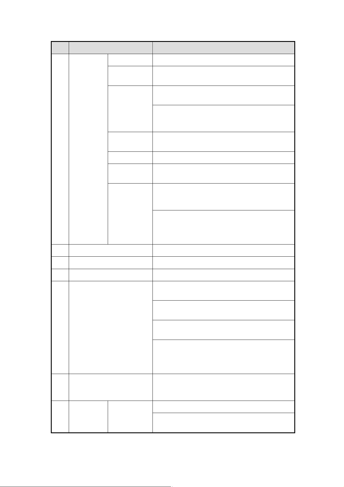
GD-RN-AP8616P and GD-RN-AP8632P:
GD-RN-AP8616P and GD-RN-AP8632P
Panel Description:
Press the button for more than 3 seconds to
turn on/off the NVR.
16
Page 17

No. Name Function Description
POWER Turns green when the NVR is powered up.
1
Status
Indicators
2 ENTER
HDD Blinks red when the HDD is reading/writing.
Tx/Rx
Blinks green when the network connection is
functioning normally.
The <Enter> button is used to confirm selection
in menu mode; or used to check checkbox fields
and ON/OFF switch.
In the <Playback> mode, it can be used to play
or pause the video.
In the Single-frame Play mode, pressing the
<Enter> button will play the video by a single
frame.
In the Auto Sequence View mode, the buttons
can be used to pause or resume the auto
sequence.
The <Enter> button is used to confirm a selection
in the <Menu> mode; or used to check checkbox
fields and as an ON/OFF switch.
In the <Menu> mode, the direction buttons are
used to navigate between different fields and
items and to select setting parameters.
In the <Playback> mode, the Up and Down
buttons are used to speed up and to slow down
the record playing; the Left and Right buttons are
3 DIRECTION
used to move the recording 30 seconds forward
or backwards.
In the Image Setting interface, the up and down
button can adjust the level bar of the image
parameters.
In the <Live View> mode, these buttons can be
used to switch channels.
4 Back Back to the previous menu.
5 POWER ON/OFF Power on/off switch.
6 MENU Access the <Main> menu interface.
Universal Serial Bus (USB) ports for additional
7 USB Interface
devices such as a USB mouse and a USB Hard
Disk Drive (HDD).
17
Page 18
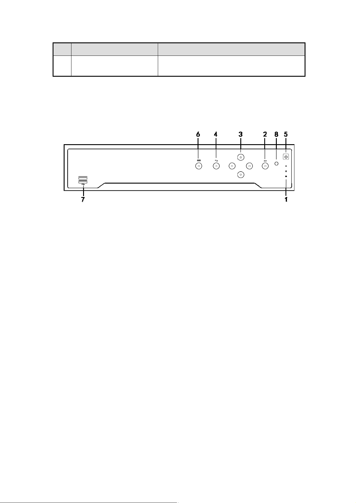
GD-RN-AC2004P, GD-RN-AC2416N and GD-RN-AC2416P:
GD-RN-AC2004P, GD-RN-AC2416N and GD-RN-AC2416P
Panel Description:
No. Name Connections
1 POWER Turns green when the NVR is powered up.
2 HDD
3 Tx/Rx
4 USB Interface
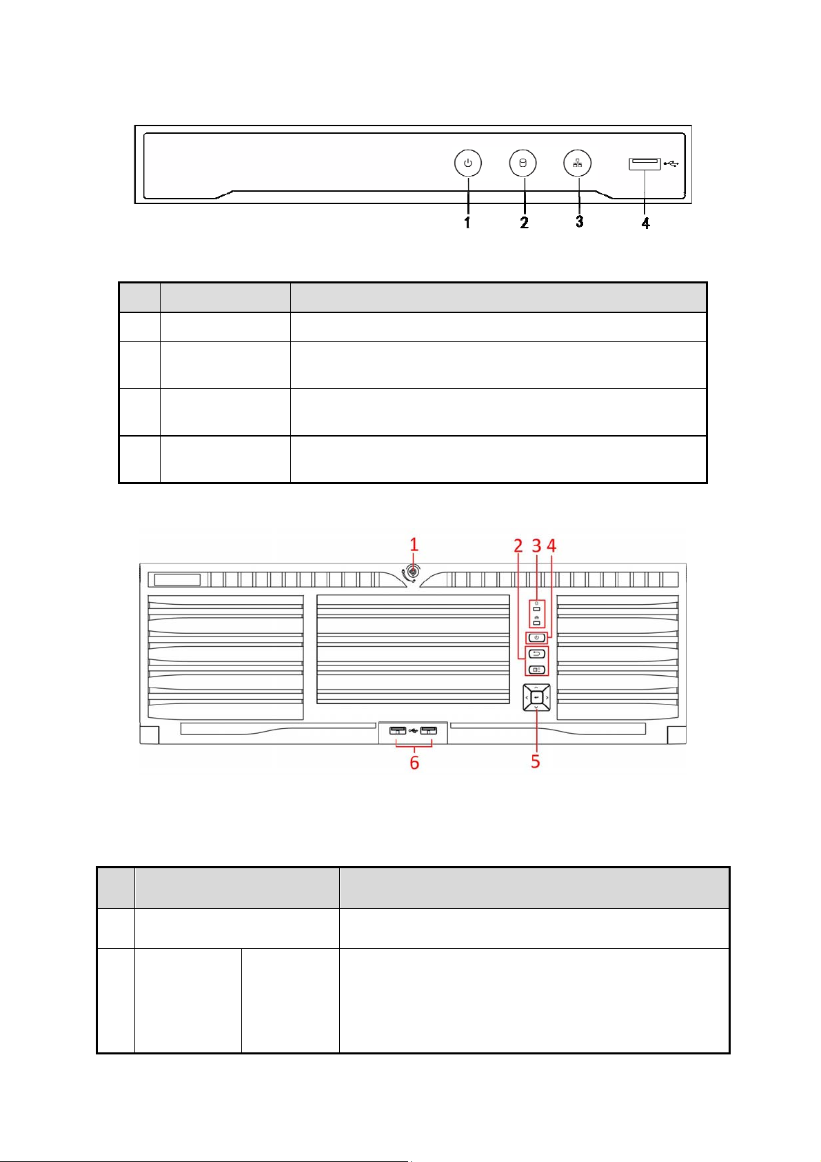
GD-RN-A T819128N:
Flickers red when data is being read from or written to the
HDD.
Flickers blue when the network connection is functioning
properly.
Universal Serial Bus (USB) port for additional devices such
as a USB mouse and a USB Hard Disk Drive (HDD).
GD-RN-AT819128N
Panel Description:
No. Name Description
1 Panel lock Locks or unlocks the panel by the key.
● Returns to the previous menu.
2
Shortcut
buttons
Exit
● Press it twice quickly to switch the main and
auxiliary port.
● In the <Live View> mode, press it to enter the
18
Page 19

No. Name Description
<PTZ Control> interface.
● Press it to bring up the <Main> menu.
● Hold it for 5 seconds to turn on/off the button
Menu
sound.
● During <Playback>, press it to show/hide the
Control Panel.
● Solid red: at least one HDD is installed
Status
3
indicators
4 Power switch
Control
5
buttons
HDD
Tx/Rx
ENTER
● Unlit: no HDD is detected.
● Blinking red: HDD is reading/writing.
Blinking blue indicates that the network communication
is normal.
Powers the device on/off. Solid blue indicates that the
device is powered on. Solid red indicates that the
device is shut down.
● Confirms a selection in any of the <Menu> modes.
● Checks the checkbox fields.
● Switches on/off status.
● Plays or pauses the video playing in the
<Playback> mode.
● Advances the video by a single frame in the Single-
frame <Playback> mode.
● Stops/starts <Auto-switch> in the <Auto-switch>
mode.
● Navigates between different fields and items in
menus.
6 USB interfaces
DIRECTION
● In the <Playback> mode, use the Up and Down
buttons to speed up and to slow down a recorded
video. Use the Left and Right buttons to select the
next and previous video files.
● Cycles through channels in the <Live View> mode.
● Controls the movement of the PTZ Camera in the
<PTZ Control> mode.
Universal Serial Bus (USB) ports for additional devices
such as a USB mouse and a USB Hard Disk Drive
19
Page 20

No. Name Description
(HDD).
1.4 Remote Control
The NVR may also be controlled with the included IR remote control, shown in 0.
Note:
Batteries (2×AAA) must be installed before operation.
The IR Remote is set at the factory to control the NVR (using default Device ID# 255) without
any additional steps. Device ID# 255 is the default universal device identification number
shared by the NVRs. You may also pair an IR Remote to a specific NVR by changing the
Device ID#, as follows:
Pairing (Enabling) the IR Remote to a Specific DVR (optional):
You can pair an IR Remote to a specific private DVR by creating a user-defined Device ID#.
This feature is useful when using multiple IR Remotes and DVRs.
On the DVR:
Steps:
1. Go to General > More Settings.
2. Type a number (255 digits maximum) into the <Device No.> field.
3. On the IR Remote:
4. Press the <DEV> button.
5. Use the Number buttons to enter the <Device ID#> that was entered into the DVR.
6. Press the <Enter> button to accept the new <Device ID#>.
20
Page 21
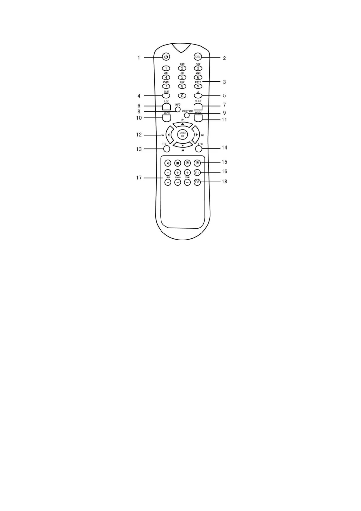
Remote Control
Unpairing (Disabling) an IR Remote from a DVR:
To unpair an IR Remote from a DVR so that the unit cannot control any DVR functions,
proceed as follows:
Press the <DEV> key on the IR Remote. Any existing Device ID# will be erased from the unit’s
memory and it will no longer function with the DVR.
Note:
(Re)-enabling the IR Remote requires pairing to a DVR. See “Pairing the IR Remote to a Specific
DVR (optional),” above.
The keys on the remote control closely resemble the ones on the front panel.
IR Remote Control Functions :
21
Page 22

No. Name Function Description
• To Turn Power On:
- If the User has not changed the default DVR
Device ID# (255):
1. Press the Power On/Off button (1).
- If the User has changed the DVR Device ID#:
1. Press the <DEV> button.
2. Press the Number buttons to enter a user-defined
Device ID#.
3. Press the <Enter> button.
4. Press the <Power> button to start the device.
• To Turn the DVR Off:
- If the User Is Logged On:
1. Hold the Power <On>/<Off> button (1) down for five
seconds to display the “Yes/No” verification prompt.
2. Use the <Up>/<Down> arrow buttons (12) to highlight the
desired selection.
3. Press the <Enter> button (12) to accept the selection.
- If the User is not logged on:
1
POWER
ON/OFF
1. Hold the Power <On>/<Off> button (1) down for five
seconds to display the <User Name>/<Password>
prompt.
2. Press the <Enter> button (12) to display the on-screen
keyboard.
3. Input the <User Name>.
4. Press the <Enter> button (12) to accept the input and
to dismiss the on-screen keyboard.
5. Use the Down arrow button (12) to move to the
<Password> field.
6. Enter the password (use the on-screen keyboard or
the numeric buttons (3) for numbers).
7. Press the <Enter> button (12) to accept the input and
to dismiss the on-screen keyboard.
8. Press the <OK> button on the screen to accept the input
and to display the <Yes>/<No> verification prompt
(use
the <Up>/<Down> Arrow buttons (12) to move
between
fields)
9. Press the <Enter> button (12) to accept the selection.
The <User Name>/<Password> prompt depends on the
DVR configuration. See the “System Configuration” section.
22
Page 23

2 DEV
3 Numerals
4 EDIT
Enable an IR Remote: Press the <DEV> button, enter the
DVR <Device ID#> with number keys, press <Enter> to pair
the unit with the DVR.
Disable an IR Remote: Press the <DEV> button to clear the
Device ID#; the unit will no longer be paired with the DVR.
Switch to the corresponding channel in the <Live View> or in
the <PTZ Control> mode.
Enter numbers in the <Edit> mode.
Delete characters before the cursor.
Check the checkbox and select the <ON>/<OFF> switch.
Adjust the focus in the <PTZ Control> menu.
5 A
Switch on-screen keyboards (upper and lower case alphabet,
symbols and numerals).
Enter the Manual Record Setting menu.
6 REC
Call a <PTZ Preset> by using the numeric buttons in the
<PTZ Control> settings.
Turn audio on/off in the <Playback> mode.
Go to the <Playback> mode.
7 PLAY
Auto-scan in the <PTZ Control> menu.
8 INFO Zoom in the PTZ Camera in the <PTZ Control> setting.
Switches between main and spot output;
9 VOIP
Zooms out the image in the <PTZ Control> mode;
Return to the <Main> menu (after successful login).
10 MENU
N/A
Show/hide full screen in the <Playback> mode.
Navigate between fields and menu items.
12 DIRECTION
ENTER
Use the <Up>/<Down> buttons to speed up/slow down a
recorded video and use the <Left>/<Right> buttons to
advance/rewind 30 seconds in the <Playback> mode.
Cycle through channels in the <Live View> mode.
Control the PTZ Camera movement in the <PTZ Control>
mode.
Confirm a selection in any <Menu> mode.
Checks a checkbox.
Play or pause a video in the <Playback> mode.
Advance video a single frame in the Single-frame <Playback>
23
Page 24

mode.
Stop/start the <Auto-switch> in the <Auto-switch> mode
13 PTZ Enter the <PTZ Control> mode.
Go back to the previous screen.
14 ESC
N/A
15 RESERVED Reserved
Select all items on a list.
16 F1
17 PTZ Control Adjust the PTZ Camera iris, focus, and zoom.
18 F2
Troubleshooting the Remote Control:
Note:
Make sure that you installed the batteries properly in the remote control. You also have to aim
the remote control at the IR receiver in the front panel.
If there is no response after you press any button on the remote control, follow the procedure
below to troubleshoot.
Steps:
1. Go to Menu > Settings > General > More Settings by operating the front control panel or the
mouse.
N/A
Switch between Play and Reverse Play in the <Playback>
mode.
Cycle through tab pages.
Switch between channels in the Synchronous <Playback>
mode.
7. Check and remember the <NVR ID#>. The default <ID#> is <255>. This <ID#> is valid for
all of the IR remote controls.
8. Press the <DEV> button on the remote control.
9. Enter the <NVR ID#> you set in step 2.
10. Press the <ENTER> button on the remote control.
If the Status indicator on the front panel turns blue, then the remote control is operating
properly. If the Status indicator does not turn blue and there is still no response from the
remote, please check the following:
‒ Batteries are installed correctly and the polarities of the batteries are not reversed.
‒ Batteries are fresh and not out of charge.
‒ The IR receiver is not obstructed.
‒ No fluorescent lamp is used nearby.
24
Page 25

If the remote control still cannot function properly, please change the remote control and try
again or contact the device provider.
25
Page 26

1.5 USB Mouse
A regular 3-button (Left/Right/Scroll-wheel) USB mouse can also be used with this NVR. To
use a USB mouse:
Steps:
1. Plug the USB mouse into one of the USB interfaces on the front panel of the NVR.
2. The mouse should automatically be detected. If, in a rare case, the mouse is not detected,
the possible reason may be that the two devices are not compatible, please refer to the
recommended device list from your provider.
The operation of the mouse:
Description of the Mouse Control:
Name Action Description
Single-Click <Live View>: Select the channel and show the Quick
Set menu.
Menu: Select and enter.
Double-Click <Live View>: Switch between single-screen and multi-
screen.
Left-Click
Click and
Drag
PTZ control: pan, tilt and zoom.
<Video Tampering>, <Privacy Mask> and <Motion
Detection>: Select the target area.
Digital zoom-in: Drag and select the target area.
<Live View>: Drag the channel/time bar.
Right-Click Single-Click <Live View>: Show menu.
Menu: Exit the current menu to the upper level menu.
ScrollWheel
Scrolling up <Live View>: Previous screen.
Menu: Previous item.
Scrolling
down
<Live View>: Next screen.
Menu: Next item.
26
Page 27
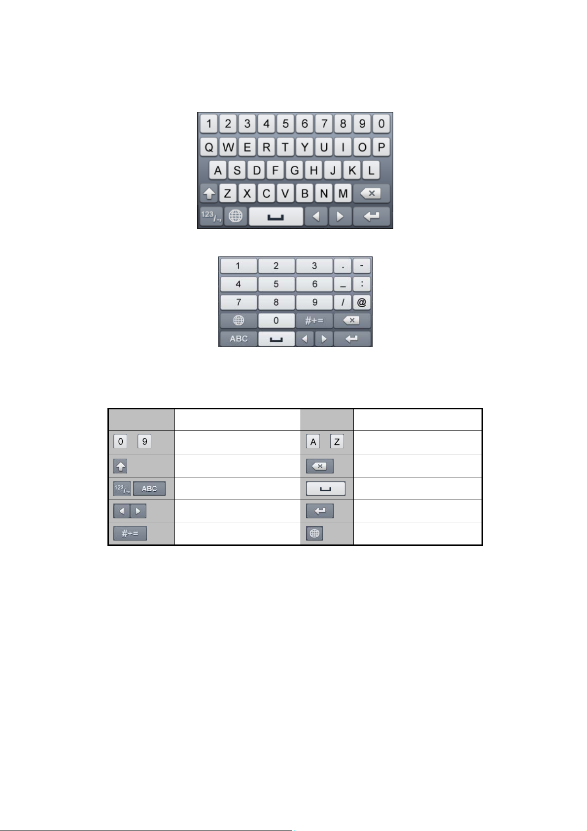
1.6 OSD Keyboard
OSD Keyboard (1)
OSD Keyboard (2)
Description of the buttons on the OSD Keyboard:
Icon Description Icon Description
…
Number
Lowercase/Uppercase
Switch the keyboard
Positioning the cursor
Symbols
…
English letter
Backspace
Space
Exit
Reserved
27
Page 28
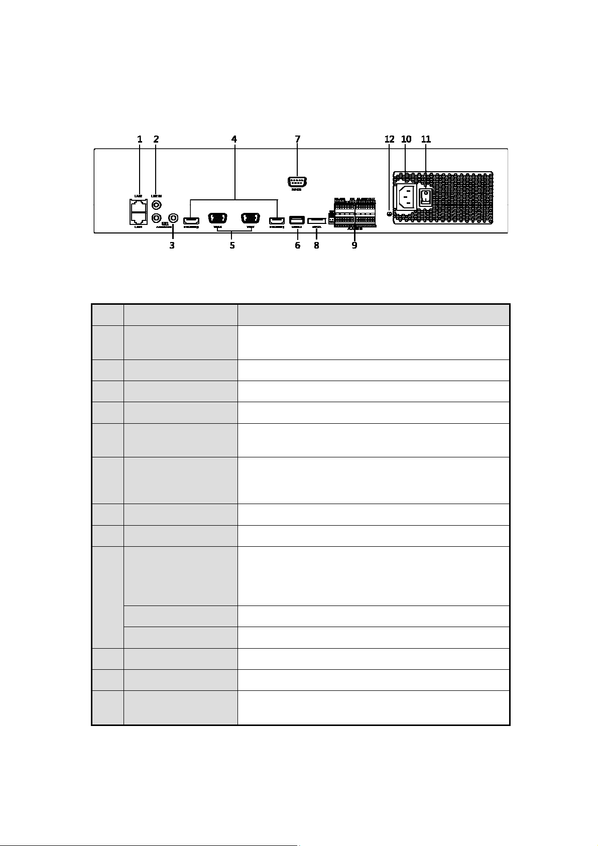
1.7 Rear Panel View
GD-RN-AT8864N:
Panel Description:
No. Name Description
GD-RN-AT8864N
1 LAN1/LAN2
Interface
2 LINE IN RCA connector for audio input.
3 AUDIO OUT 2 RCA connectors for audio output.
4 HDMI1/HDMI2 HDMI video output connector.
5 VGA1/VGA2 DB9 connector for VGA output. Display local video
6 USB 3.0 interface Universal Serial Bus (USB) ports for additional
7 RS-232 Interface Connector for RS-232 devices.
8 eSATA Connects external SATA HDD, CD/DVD-RM.
Controller Port
9
ALARM IN Connector for <Alarm Input>.
2 RJ-45 10/100/1000 Mbps self-adaptive Ethernet
interfaces are provided.
output and menu.
devices such as a USB mouse and a USB Hard Disk
Drive (HDD).
D+, D- pin connects to the Ta, Tb pin of the
controller. For cascading devices, the first NVR’s D+,
D- pin should be connected with the D+, D- pin of the
next NVR.
ALARM OUT Connector for alarm output.
10 100 to 240 VAC 100 to 240 VAC power supply.
11 Power Switch Switch for turning the device on/off.
12 GROUND Ground (needs to be connected when the NVR starts
up).
28
Page 29
GD-RN-AC2416N and GD-RN-AC2416P:
GD-RN-AC2416N
Panel Description:
No. Name Description
1 Audio In
2 Audio Out
3 VGA Interface
4 HDMI Interface
5 ALARM IN
ALARM OUT
6 LAN Network Interface
andGD-RN-AC2416P
RCA connector for audio input.
RCA connector for audio output.
DB9 connector for VGA output. Display local video
output and menu.
HDMI video output connector.
Connector for <Alarm Input>.
Connector for alarm output.
1 10/100/1000 Mbps self-adaptive Ethernet
interface
7 USB Interface
8 Ground
9 Power Supply
10 Power Switch
Universal Serial Bus (<USB 3.0>) ports for
additional devices such as USB mouse and USB
Hard Disk Drive (HDD).
Ground (needs to be connected when the NVR
starts up).
See the Specification Sheet of the NVR.
Switch for turning the device on/off.
29
Page 30
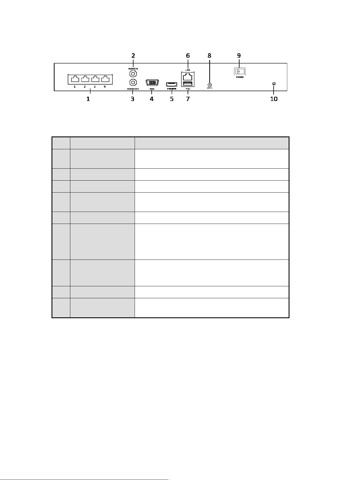
GD-RN-AC2004P:
Panel Description:
No. Name Description
GD-RN-AC2004P
1 Network Interfaces
with PoE function
2 Audio In RCA connector for audio input.
3 Audio Out RCA connector for audio output.
4 VGA Interface DB9 connector for VGA output. Display local video
5 HDMI Interface HDMI video output connector.
6 LAN Network
Interface
7 USB Interface Universal Serial Bus (USB) ports for additional
9 Power Supply 48 VDC power supply.
10 Ground Ground (needs to be connected when the NVR starts
Network interfaces for the cameras and to provide
power over Ethernet.
output and menu.
1 10/100/1000 Mbps self-adaptive Ethernet interface
for GD-RN-AC2004P ;
1 100 Mbps full-duplex Ethernet interface for GD-RNAC2004P
devices such as a USB mouse and a USB Hard Disk
Drive (HDD).
up).
30
Page 31

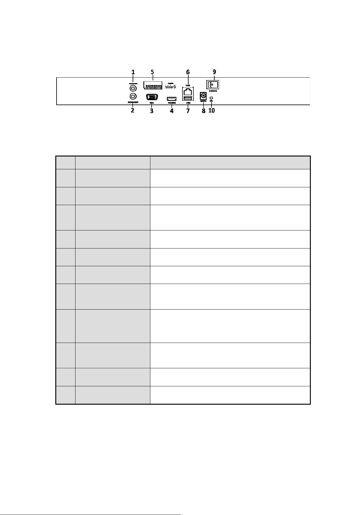
GD-RN-AP8616P and GD-RN-AP8632P:
GD-RN-AP8616P and GD-RN-AP8632P
Panel Description:
No. Name Description
1 LAN Interface 1 network interface.
2 AUDIO OUT RCA connector for audio output.
3 LINE IN RCA connector for audio input.
4 HDMI HDMI video output connector.
5 USB 3.0 interface Universal Serial Bus (USB) ports for additional
devices such as a USB mouse and a USB Hard Disk
Drive (HDD).
6 RS-232 Interface Connector for RS-232 devices.
7 VGA DB9 connector for VGA output. Display local video
output and menu.
8 RS-485 Interface Half-duplex connector for RS-485 devices.
9 ALARM IN Connector for <Alarm Input>.
ALARM OUT Connector for alarm output.
10 GROUND Ground (needs to be connected when the NVR starts
up).
11 AC 100V ~ 240V 100V to 240VAC power supply.
12 Power Switch Switch for turning the device on/off.
13 Network Interfaces
with PoE function
Network interfaces for the cameras and to provide
power over Ethernet.
31
Page 32

GD-RN-AT819128N
:
GD-RN-AT819128N
Panel Description:
No. Name Description
1 HDMI 1/2 HDMI video output connector.
2 Audio in RCA connector for audio input.
Audio out RCA connector for audio output.
3 USB 3.0 Universal Serial Bus (USB 3.0) ports for additional devices
such as a USB mouse and a USB Hard Disk Drive (HDD).
4 LAN 4 10/100/1000 Mbps self-adaptive Ethernet interfaces.
5 eSATA Connects external SATA HDD, CD/DVD-RM.
6 VGA DB9 connector for VGA output.
7 Mini SAS
Connector for mini SAS.
(optional)
8 Reset <Reset> button.
9 RS-232 Connector for RS-232 devices.
10 Alarm in Connector for <Alarm Input>.
Alarm out Connector for alarm output.
RS-485 Connector for RS-485 devices.
32
Page 33

KB Connector for the keyboard.
11 GND Ground (needs to be connected when the NVR starts up).
12 Power supply
modules
13 Decoding
board
Only one power supply module is provided by default. Two
power supply modules are optional for redundancy.
Not Available.
2. Getting Started
2.1 Recorder Startup
Proper startup and shutdown procedures are crucial to expanding the life of the NVR.
Before you start:
Check that the voltage of the extra power supply is the same as the NVR’s requirement and
that the ground connection is working properly.
Starting up the NVR:
Steps:
1. Check that the power supply is plugged into an electrical outlet. It is HIGHLY recommended
that an Uninterruptible Power Supply (UPS) be used in conjunction with the device. The
Power indicator LED on the front panel should be red, indicating that the device gets the
power supply.
2. Press the <POWER> button on the front panel. The Power indicator LED should turn blue,
indicating that the unit begins to start up.
3. After startup, the Power indicator LED remains blue. A splash screen with the status of the
HDD appears on the monitor. The row of icons at the bottom of the screen shows the HDD
status. ‘X’ means that the HDD is not installed or that it cannot be detected.
Shutting down the NVR:
There are two proper ways to shut down the NVR.
OPTION 1: Standard shutdown
Steps:
1. Enter the Shutdown menu: Menu > Shutdown
33
Page 34

4. Click the <Shutdown> button.
5. Click the <Yes> button.
Shutdown Menu
OPTION
Steps:
2: By operating the front pane
2. Press and hold the <POWER> button on the front panel for 3 seconds.
3. Enter the <Administrator’s User Name> and <Password> in the dialog box for
authentication.
4. Click the <Yes> button.
Note:
Do not press the <POWER> button again when the system is shutting down.
Rebooting the NVR:
In the Shutdown menu, you can also reboot the NVR.
Steps:
1. Enter the <Shutdown> menu by clicking Menu > Shutdown.
2. Click the <Logout> button to lock the NVR or the <Reboot> button to reboot the NVR.
Activating your Recorder:
For the first-time access, you need to activate the device by setting an Admin Password. No
operation is allowed before activation. You can also activate the device via a Web Browser,
Grundig Viewer or the SCMS Client Software.
Steps:
1. Enter the same password in the text field of <Create New Password> and <Confirm New
Password>.
34
Page 35

Settings Admin Password
WARNING:
We highly recommend you create a strong password of your own choosing (Using a minimum
of 8 characters, including at least three of the following categories: upper case letters, lower
case letters, numbers and special characters.) in order to increase the security of your product.
We also recommend that you reset your password regularly, especially in the high security
system, resetting the password monthly or weekly can better protect your product.
2. Click <OK> to save the password and to activate the device.
3. When the device is activated, the system pops up the message box to remind you to
remember the password. Then you can click <Yes> to continue to export the GUID file for the
future password resetting.
Export GUID File Remind
4. Insert the U-flash disk to your device, and export the GUID file to the U-flash disk in the
<Reset Password> interface. Please refer to the Chapter Resetting Your Password for the
instructions of password resetting.
Export GUID File
35
Page 36

Note:
Please keep your GUID file properly for future password resetting. This GUID Export function
may not be available for the GD-RN-AT819128N.
Using the Unlock Pattern for Login:
For the Admin User, you can configure the unlock pattern for the device login.
Configuring the Unlock Pattern:
Steps:
1. After the device is activated, you can enter the following interface to configure the device
unlock pattern.
Set the Unlock Pattern
2. Use the mouse to draw a pattern among the nine dots on the screen. Release the mouse
when the pattern is done.
Draw the Pattern
Note:
‒ Connect at least four dots to draw the pattern.
‒ Each dot can be connected once only.
3. Draw the same pattern again to confirm it. When the two patterns match, the pattern is
configured successfully.
36
Page 37

Confirm the Pattern
Note:
If the two patterns are different, you must set the pattern again.
Re-set the Pattern
Logging in via Unlock Pattern:
Note:
‒
Only the Admin User has the permission to unlock the device.
‒
Please configure the pattern first before unlocking. Please refer to Configuring the Unlock
Pattern
1. Right-click the mouse on the screen and select the menu to enter the interface as shown
below.
37
Page 38

Draw the Unlock Pattern
2. Draw the pre-defined pattern to unlock to enter the menu operation.
Note:
‒
If you forgot your pattern, you can select the <Forget My Pattern> or the <Switch User> option
to enter the normal <Login> dialog box.
‒
When the pattern you draw is different from the pattern you have configured, you should try
again.
‒
If you have drawn the wrong pattern for more than 5 times, then the system will switch to the
normal login mode automatically.
Normal Login Dialog Box
Login and Logout:
- User Login:
If the NVR has logged out, you must log in the device before operating the menu and other
functions.
3. Select the <User Name> in the dropdown list.
38
Page 39

Login Interface
4. Enter the <Password>.
5. Click <OK> to log in.
Note:
When you forget the password of the Admin User, then you can click <Forget Password> to
reset the password. Please refer to Chapter Resetting Your Password for details.
Note:
In the <Login> dialog box, if you enter the wrong password 7 times, then the current user
account will be locked for 60 seconds.
User Logout
After logging out, the monitor turns to the <Live View> mode and if you want to perform any
operations, you need to enter the User Name and the Password again.
Steps:
1. Enter the Shutdown menu: Menu > Shutdown
Logout
2. Click <Logout>.
Note:
After you have logged out the system, menu operation on the screen is invalid. It is required to enter
a user name and password to unlock the system.
Resetting Your Password:
When you forget the password of the Admin User, you can reset the password by importing the
GUID file. The GUID file must be exported and saved in the local U-flash disk after you
have activated the device (refer to Chapter 17.5.3).
3. On the user login interface, click <Forget Password> to enter the <Reset Password>
interface.
39
Page 40

Note:
Please insert the U-flash disk stored with the GUID file to the NVR before resetting the password.
Reset Password
4. Select the GUID file from the U-flash disk and click <Import> to import the file to the
device.
Note:
If you have imported the wrong GUID file for 7 times, you will not be allowed to reset the password
for 30 minutes.
5. After the GUID file is successfully imported, enter the reset password interface to set the
new admin password. Refer to Chapter 17.5.3.
6. Click <OK> to set the new password. You can export the new GUID file to the U-flash disk
for future password resetting.
Note:
When the new password is set, the original GUID file will be invalid. The new GUID file should
be exported for future password resetting. You can also enter the User>User Management
interface to edit the Admin User and to export the GUID file.
2.2 Using the Wizard for Basic Configuration
By default, the Setup Wizard starts once the NVR has loaded, as shown below.
40
Page 41

Start Wizard Interface
Operating the Setup Wizard:
Steps:
1. The Setup Wizard can walk you through some important settings of the NVR. If you don’t
want to use the Setup Wizard at that moment, click the <Cancel> button. You can also
choose to use the Setup Wizard next time by leaving the <Start wizard when the device
starts?> checkbox checked.
2. Click the <Next> button to enter the Date and Time Settings window, as shown below.
Date and Time Settings
3. After the time settings, click the <Next> button which takes you back to the Network Setup
Wizard window, as shown in the following Picture.
41
Page 42

Network Settings
Note:
Two self-adaptive 10M/100M/1000M network interfaces provided for GD-RN-AT8864N, GD-RNAP8616P and GD-RN-AP8632P and two working modes are configurable: Multi-address and
Network Fault tolerance. Also one self-adaptive 10M/100M/1000M network interface is provided
for GD-RN-AC2416N, GD-RN-AC2416P, GD-RN-AP8616P and GD-RN-AP8632P.
4. Click the <Next> button after you configured the basic network parameters. Then you will
enter the <Cloud P2P> interface. Configure the <Cloud P2P> according to your need.
Advanced Network Parameters
5. Click the <Next> button after you configured the basic network parameters. Then you will
enter the <Advanced Network Parameter> interface. You can enable <UPnP>, <DDNS>
and set other ports according to your need.
42
Page 43

Advanced Network Parameters
6. Click the <Next> button after you configured the network parameters, which takes you
to the RAID configuration window.
Note:
The RAID is supported by GD-RN-AT8864N and GD-RN-AT819128N only.
Array Management
7. Click the <Next> button to enter the Array Management window.
8. Click the <Next> button after you configured the network parameters, which takes you
to the <HDD Management> window, shown below.
HDD Management
43
Page 44

9. To initialize the HDD, click the <Init> button. Initialization removes all the data saved in the
HDD.
10. Click the <Next> button. You enter the <Adding IP Camera> interface.
11. Click <Search> to search the online IP Camera and the Security status shows whether it
is active or inactive. Before adding the camera, make sure the IP Camera to be added
shows an active status.
If the camera shows an inactive status, then you can click the inactive icon of the camera to
set the password to activate it. You can also select multiple cameras from the list and click
the <One-touch Activate> to activate the cameras in batch.
Click the <Add> button to add the camera.
Search for IP Cameras
Note:
When you check the checkbox of <Enable H.265>, the NVR can automatically switch to the
H.265 stream of the IP camera (which supports H.265 video format) for the initial access.
12. Click the <Next> button. Configure the recording for the added IP Cameras.
Record Settings
13. Click <OK> to complete the startup Setup Wizard.
44
Page 45

2.3 Adding and Connecting the IP Cameras
2.3.1 Activating the IP Camera
Before adding the camera, make sure the IP camera to be added is in active status.
Steps:
1. Select the <Add IP Camera> option from the right-click menu in the <Live View> mode or
click Menu> Camera> Camera to enter the <IP Camera Management> interface.
For the IP camera detected online in the same network segment, the <Password> status shows
whether it is active or inactive.
<IP Camera Management> interface
2. Click the inactive icon of the camera to enter the following interface to activate it. You can
also select multiple cameras from the list and click the <One-touch Activate> to activate the
cameras in batch.
Activate the Camera
3. Set the password of the camera to activate it.
45
Page 46

<Use Admin Password>: when you check the checkbox, the camera (s) will be configured with the
same admin password of the operating NVR.
Set New Password
<Create New Password>: If the admin password is not used, you must create the new password
for the camera and confirm it.
WARNING:
Strong Password recommended–We highly recommend you create a strong password of your
own choosing (Using a minimum of 8 characters, including at least three of the following categories:
upper case letters, lower case letters, numbers and special characters.) in order to increase the
security of your product. And we recommend you reset your password regularly, especially in the
high security system, resetting the password monthly or weekly can better protect your product.
4. Click <OK> to finish the acitavting of the IP camera. Then the security status of camera will
be changed to <Active>.
2.3.2 Adding the Online IP Cameras
The main function of the NVR is to connect the network cameras and to record the video
received by it. So before you can get a <Live View> or a record of the video, you should add
the network cameras to the connection list of the device.
Before you start:
Ensure the network connection is valid and correct. For detailed checking and configuring of
the network, please see the Chapter about 12.3 Checking Network Traffic and the Chapter
about 12.4 Configuring Network Detection.
Adding the IP Cameras:
OPTION 1:
Steps:
1. Click to select an idle window in the <Live View> mode.
2. Click the
icon in the center of the windw to pop up the Adding IP camera interface.
3. Select the detected IP camera and click the <Add> button to add it directly, and you can
click the <Search> button to refresh the online IP camera manually.
46
Page 47

Quick Adding IP Camera Interface
Or you can choose to custom add the IP camera by editing the parameters in the
corresponding textfiled and then click the <Add> button to add it.
OPTION 2:
Steps:
1. Select the <Add IP Camera> option from the right-click menu in the <Live View> mode or
click Menu> Camera> Camera to enter the <IP Camera Management> interface.
Adding IP Camera Interface
2. The online cameras with the same network segment will be detected and displayed in the
camera list.
3. Select the IP camera from the list and click the
click the <One-touch Adding> button to add all cameras (with the same login password)
from the list.
Note:
Make sure the camera to add has already been activated.
OPTION 3:
Steps:
1. On the <IP Camera Management> interface, click the <Custom Adding> button to pop up
the Add IP Camera (Custom) interface.
47
button to add the camera. Or you can
Page 48

Custom Adding IP Camera Interface
2. You can edit the <IP Address>, <Protocol>, <Management Port>, and other information of
the IP camera that is to be added.
Note:
If the IP camera that is to be added has not been actiavated, you can activate it from the IP camera
list on the Camera Management interface.
3. (Optional) Check the checkbox of <Continue to Add> to add other IP cameras.
4. Click <Add> to add the camera. The successfully added cameras are listed in the
interface.
Refer to the following table for the description of the icons:
Description of Icons:
Icon Explanation Icon Explanation
camera
Edit basic parameters of the
Add the detected IP camera.
The camera is disconnected;
the exception information of
you can click the icon to get
Delete the IP camera
the camera.
Play the live video of the
connected camera.
Advanced settings of the
camera.
Show the security status of
Upgrade the connected IP
camera.
Security
the camera to be
active/inactive or the
password strength
(strong/medium/weak/risk)
Note:
For the added IP cameras, the <Security> status shows the security level of the camera’s
password: <Strong Password>, <Weak Password> and <Risk Password>.
48
Page 49

Security Level of an IP Camera’s Password
Enabling the Password of Visible IP Cameras:
For the admin login user account, you can check the checkbox of <Show Password of IP
Camera> to enable the showing of the passwords of the successfully added IP cameras in the
list.
You must enter the admin password to confirm permission.
List of Added IP Cameras
Enabling the H.265 Stream Access:
You can check the checkbox of <Enable H.265>, the NVR can automatically switch to the
H.265 stream of the IP camera (which supports an H.265 video format) for the initial access.
2.3.3 Editing the Connected IP Cameras and Configuring Customized Protocols
After the adding of the IP cameras, the basic information of the camera lists in the page, you
can configure the basic setting of the IP cameras.
Steps:
1. Click the
other parameters.
icon to edit the parameters; you can edit the <IP Address>, the <Protocol> and
Edit the Parameters
49
Page 50

<Channel Port>: If the connected device is an encoding device with multiple channels, you
can choose the channel to connect by selecting the <Channel Port> number in the dropdown
list.
2. Click <OK> to save the settings and exit the Editing interface.
To edit advanced parameters:
Steps:
1. Drag the horizontal scroll bar to the right side and click the icon.
Network Configuration of the Camera
2. You can edit the network information and the <Password> of the camera.
Password Configuration of the Camera
3. Click <OK> to save the settings and to exit the interface.
Configuring the customized protocols:
Toconnectthenetworkcameraswhicharenotconfiguredwiththestandardprotocols,
youcanconfigurethecustomizedprotocolsforthem.
Steps:
1. Click the <Protocol> button in the Custom Adding IP camera interface to enter the Protocol
Management interface.
50
Page 51

Protocol Management Interface
There are 16 customized protocols provided in the system, you can edit the <Protocol
Name>; and choose whether to enable the Sub-stream.
2. Choose the protocol type of transmission and choose the transfer protocols.
Note:
Before customizing the protocol for the network camera, you have to contact the
manufacturer of the network camera to consult the URL (uniform resource locator) for
getting main stream and sub-stream.
The format of the URL is: [Type]://[IP Address of the network camera]:[Port]/[Path].
Example: rtsp://192.168.1.55:554/ch1/main/av_stream.
<Protocol Name>: Edit the name for the <Custom Protocol>.
<Enable Sub-stream>: If the network camera does not support <Sub-stream> or if the
<Sub-stream> is not needed, leave the checkbox empty.
<Type>: The network camera adopting <Custom Protocol> must support getting stream
through standard <RTSP>.
<Transfer Protocol>: Select the <Transfer Protocol> for the <Custom Protocol>.
<Port>: Set the <Port> number for the <Custom Protocol>.
<Path>: Set the <Resource Path> for the <Custom Protocol>. E.g., ch1/main/av_stream.
Note:
The <Protocol Type> and the <Transfer Protocols> must be supported by the connected
network camera.
After adding the customized protocols, you can see the protocol name is listed in the
dropdown list.
51
Page 52

Protocol Setting
3. Choose the protocols you just added to validate the connection of the network camera.
2.3.4 Editing the IP Cameras Connected to the PoE Interfaces
This chapter is only applicable for the following models: GD-RN-AP8616P, GD-RN-AP8632P, GDRN-AC2416P and GD-RN-AC2004P.
The <PoE> interface enables the NVR system to pass electrical power safely along with data
on Ethernet cabling to the connected network cameras.
Up to 4 network cameras can be connected to 4-Port models, 8 network cameras to 8-Port
models, and 16 network cameras to 16-Port models. If you disable the PoE interface, you can
also connect to the online network cameras. And the PoE interface supports the Plug-and-Play
function.
Example:
For GD-RN-AP8616P, if you want to connect 6 network cameras via PoE interfaces and 2
online cameras, you must disable 10 PoE interfaces in the Edit IP Camera menu.
To add Cameras for NVR supporting the <PoE> function:
Before you start:
Connect the network cameras via the <PoE> interfaces.
Steps:
1. Enter the <Camera Management> interface: Menu> Camera> Camera
52
Page 53

List of Connected Cameras
Note:
The cameras connecting to the <PoE> interface cannot be deleted in this menu.
2. Click the button, and select the <Adding Method> in the drop-down list.
• <Plug-and-Play>: It means that the camera is connected to the <PoE> interface, so in
this case, the parameters of the camera can’t be edited. The <IP Address> of the
camera can only be edited in the <Network Configuration> interface, see Chapter 11.1
12.1 Configuring General Settings for detailed information.
Edit IP Camera Interface - Plug-and-Play
• Manual: You can disable the <PoE> interface by selecting the manual while the current
channel can be used as a normal channel and the parameters can also be edited.
Input the <IP Address>, the <User Name> and the <Password> of the administrator manually
and Click <OK> to add the IP Camera.
53
Page 54

Edit IP Camera Interface – Manual
2.3.5 Configuring the PoE Interface
When it requires long-distance <PoE> transmission (100 to 300 m), you can configure the
<PoE> channel to the long network cable mode.
Steps:
1. Enter the <PoE Configuration> interface.
2. Menu> Camera> Camera> PoE Configuration
3. Click the radio button of each <PoE> channel to switch
button of the <PoE Channel> to enable or disable the long network cable mode.
4. <ON>: Long-distance (100 - 300 meters) network transmissions via the <PoE> interface.
5. <OFF>: Short-distance (< 100 meters) network transmission via the <PoE> interface.
Configure the PoE Interface
and . You can click the radio
54
Page 55

Note:
‒
The <PoE> is enabled with the short network cable mode (<OFF>) by default.
‒
The bandwidth of the IP Camera connected to the <PoE> via a long network cable (100 300 meters) cannot exceed 6 MP.
‒
The allowed max. long network cable may be less than 300 meters, depending on different
IP Camera models.
‒
When the transmission distance reaches 100 to 250 meters, it must use the CAT5E or CAT6
network cable to connect with the <PoE> interface.
‒
When the transmission distance reaches 250 to 300 meters, it must use the CAT6 network
cable to connect with the <PoE> interface.
‒
Refer to chapter 19 for the list of IP cameras.
Note:
You can check the connecting status and power information of the <POE> channel on the
interface.
6. Click <Back> to finish the settings.
55
Page 56

3. Live View
3.1 Introduction of Live View
<Live View> shows you the video image received from each camera in real time. The NVR
automatically enters the <Live View> mode when it is powered on. It is also at the very top of
the menu hierarchy, thus pressing the <ESC> button many times (depending on which menu
you’re on) brings you to the <Live View> mode.
<Live View> Icons:
In the <Live View> mode, there are icons at the upper-right of the screen for each channel,
showing the status of the <Record> and <Alarm> in the channel, so that you can know as soon
as possible whether the channel is recorded or whether alarms occur.
Description of <Live View> Icons:
Icons Description
<VCA> and <Sensor Alarm>)
Record (<Manual Record>, <Schedule Record>, <Motion
Alarm (<Video Loss>, <Video Tampering>, <Motion Detection>,
Detection>, <VCA> and <Alarm Triggered Record>)
<Alarm> and <Record>
<Event>/<Exception> (<Motion Detection>, <VCA>, <Sensor
Alarm> or <Exception> information, appears at the lower-left
corner of the screen. Please refer to Chapter Setting Alarm
Response Actions for details.)
56
Page 57

3.2 Operations in the Live View mode
In the <Live View> mode, there are many functions provided. The functions are listed below.
• <Single Screen>: showing only one screen on the monitor.
• <Multi-screen>: showing multiple screens on the monitor simultaneously.
• <Auto-switch>: the screen is auto-switched to the next one. And you must set the <Dwell
Time> for each screen on the configuration menu before enabling the <Auto-switch>.
Menu> Configuration> Live View> Dwell Time.
• <Start Recording>: <Continuous Record> and <Motion Detection Record> are supported.
• <Output Mode>: Select the output mode to <Standard>, <Bright>, <Gentle> or <Vivid>.
• <Add IP Camera>: This is a shortcut to the <IP Camera Management> interface.
• <Playback>: Playback the recorded videos for the current day.
• <Aux Monitor>: the NVR checks the connection of the output interfaces to define the main
and auxiliary output interfaces. The priority level for the main and aux output is
HDMI1/VGA1> HDMI2/VGA2 (for GD-RN-AT8864N) and HDMI> VGA (for GD-RNAC2416N, GD-RN-AC2416P, GD-RN-AC2004P, GD-RN-AP8616P and GD-RN-AP8632).
GD-RN-AT8864N: When the HDMI1, HDMI2, VGA1 and VGA2 are all connected, the
HDMI1/VGA1 is used as main output and the HDMI2/VGA2 is used as the aux output.
GD-RN-AC2004P, GD-RN-AC2416N, GD-RN-AC2416P, GD-RN-AP8616P and GD-RNAP8632P: When both the HDMI and VGA are connected, the HDMI is used as main output and
the VGA is used as the aux output.
For GD-RN-AT819128N the following applies: To configure HDMI 1 and VGA Simultaneous
Output> and <Menu Output> Mode, refer to the corresponding Chapter.
Main and Auxiliary Output Priority Principle (for GD-RN-AT819128N):
HDMI 1 and VGA
Simultaneous
Output
Enabled
Menu Output
Mode
Auto HDMI 1 > HDMI 2/VGA
HDMI 1/VGA HDMI 1/VGA > HDMI 2
HDMI 2 HDMI 2 > HDMI 1/VGA
Auto HDMI 1 > VGA > HDMI 2
Main and Auxiliary Output
Priority
Disabled
VGA VGA > HDMI 1 > HDMI 2
HDMI 1 HDMI 1 > VGA > HDMI 2
57
Page 58

HDMI 2 HDMI 2 > VGA > HDMI 1
When the <Aux Output> is enabled, the main output cannot perform any operation, and you
can do some basic operation on the <Live View> mode for the <Aux Output>.
Front Panel Operation on <Live View>:
Functions Front Panel Operation
Show single
screen
Press the corresponding Alphanumeric button. E.g. Press 2
to display only the screen for channel 2.
Show multi-screen Press the PREV/FOCUS- button.
Manually switch
screens
Next screen: <Right>/<Down> direction button.
Previous screen: <Left/Up> direction button.
Auto-switch Press the <Enter> button.
Playback Press the <Play> button.
Switch between
Press the <Main>/<Aux> button.
main and aux
output
Using the Mouse in <Live View>:
58
Page 59

Name Description
Common Menu Quick access to the sub-menus which you frequently visit.
Menu
Single Screen
Enter the <Main> menu of the system by right clicking the
mouse.
Switch to the single full screen by choosing a channel number
from the dropdown list.
Multi-screen Adjust the screen layout by choosing from the dropdown list.
Previous Screen Switch to the previous screen.
Next Screen Switch to the next screen.
Start/Stop Autoswitch
Start Recording
Add IP Camera
Playback
Enable/disable the <Auto-switch> of the screens.
Start <Continuous Recording> or <Motion Detection
Recording> of all channels.
Enter the <IP Camera Management> interface and manage
the cameras.
Enter the <Playback> interface and start playing back the
video of the selected channel immediately.
PTZ Enter the <PTZ Control> interface.
Output Mode
Aux Monitor
Note:
‒
The <Dwell Time> of the <Live View> configuration must be set before using <Start Auto-
switch>.
‒
If you enter the <Aux Monitor> mode and the <Aux Monitor> is not connected, then the mouse
operation is disabled; you need to switch back to the <Main> output with the <MAIN>/<AUX>
button on the front panel or on the remote.
‒
If the corresponding camera supports the <Intelligent> function, then the <Reboot Intelligence>
option is included when right-clicking the mouse on this camera.
Four modes of output are supported including <Standard>,
<Bright>, <Gentle> and <Vivid>.
Switch to the auxiliary output mode and the operation for the
main output is disabled.
Right-click Menu
59
Page 60

Using an Auxiliary Monitor:
Certain features of the <Live View> are also available while in an Aux monitor. These features
include:
<Single Screen>: Switch to a full screen display of the selected camera. Camera can be
selected from a dropdown list.
<Multi-screen>: Switch between different <Display Layout> options. Layout options can be
selected from a dropdown list.
<Next Screen>: When displaying less than the maximum number of cameras in the <Live
View>, clicking this feature will switch to the next set of displays.
<Playback>: Enter into the <Playback> mode.
<PTZ Control>: Enter the <PTZ Control> mode.
<Main Monitor>: Enter the <Main Operation> mode.
Note:
In the <Live View> mode of the main output monitor, the menu operation is not available while Aux
output mode is enabled.
Quick Setting Toolbar in the <Live View> mode:
On the screen of each channel, there is a <Quick Setting Toolbar> which displays when you
single-click the mouse in the corresponding screen.
Quick Setting Toolbar
Note:
The fisheye expansion view feature is supported by the models GD-RN-AP8616P, GD-RNAP8632P, GD-RN-AT8864N only.
60
Page 61

Description of Quick Setting Toolbar Icons:
Icon Description Icon Description Icon Description
Enable/Disable
Manual
Record
Capture
Image Settings
Instant
Playback
PTZ Control
Face
Detection
Mute/Audio
on
Digital Zoom
Live View
Strategy
3D
Positioning
Information
Close
(only for
some NVR
models)
Main/SubStream
<Instant Playback> only shows the record from the last five minutes. If no record is found,
it means there is no record during the last five minutes.
<3D Positioning> (for GD-RN-AP8616P, GD-RN-AP8632P and GD-RN-AT8864N) is for
zooming in to/out of the specific area of a live image.
Use the left key of mouse to click on the desired position in the video image and drag a
rectangle area in the lower right direction, the camera will move the position to the center and
enable the rectangle area to zoom in. Use the left key of the mouse to drag a rectangle area in
the upper left direction to move the position to the center and to enable the rectangle area to
zoom out.
<Digital Zoom> is for zooming in on the live image. You can zoom in the image to different
proportions (1 to16X) by moving the sliding bar from <-> to <+>. You can also scroll the mouse
wheel to control the zoom in/out.
The <Image Settings> icon can be selected to enter the <Image Settings> menu.
You can set the image parameters like <Brightness>, <Contrast>, <Saturation> and <Hue>
according to the actual demand.
Image Settings- Customize
61
Page 62

<Live View Strategy> can be selected to set a strategy including <Real-time>,
<Balanced> and <Fluency>.
Live View Strategy
The <Face detection> function can be used to detect the human faces in the <Live
View> mode and to save them in HDD. When there are human faces with the specified size
detected in the front of the camera, the device will capture the human face and save it in HDD.
Move the mouse onto this icon to show the <Real-time Stream Information> including
the <Frame Rate>, the <Bitrate>, the <Resolution> and the <Stream Type>.
Information
Fisheye Expansion View:
Some NVR recorders (
<Fisheye Expansion> for a connected <Fisheye Camera> in the <Live View> or in the
<Playback> mode.
Click on the icon
GD-RN-AP8616P, GD-RN-AP8632P and GD-RN-AT8864N) support the
to enter the <Fisheye Expansion> mode.
Fisheye Display Mode:
Button Operation
180° panorama
360° panorama
PTZ expansion
Fisheye
expansion
Fisheye
62
Page 63

Four different display modes are available. You can select a display mode as demand.
<180° Panorama>: Switch the <Live View> image to the <180° Panorama> view.
<360° Panorama>: Switch the <Live View> image to the <360° Panorama> view.
<PTZ Expansion>: The <PTZ Expansion> is the close-up view of some defined area in
the <Fisheye View> or a panorama expansion and it supports the electronic <PTZ>
function which is also called <e-PTZ>.
<Fisheye>: In the <Fisheye> mode, the whole wide-angle view of the Fisheye Camera
is displayed. This view mode is called <Fisheye View> because it approximates the
vision of a fish’s convex eye. The lens produces curvilinear images of a large area
while distorting the perspective and angles of objects in the image.
63
Page 64

3.3 Adjusting the Live View Settings
<Live View Settings> can be customized according to different needs. You can configure the
<Output Interface>, the <Dwell Time> for the screen to be shown and <Mute> or turn on the
<Audio>. You can configure the <Screen Number> for each channel, etc.
Steps:
1. Enter the <Live View Settings> interface: Menu> Configuration> Live View
Live View-General
The settings available in this menu include:
<Video Output Interface>: Designates the output to configure the settings.
<VGA/HDMI and <VGA2/HDMI2> are provided for GD-RN-AT8864N.
HDMI 1, HDMI 2, and VGA outputs are provided for GD-RN-AT819128N (HDMI 2 video
output at up to 4K resolution).
HDMI and VGA outputs are provided for GD-RN-AC2004P, GD-RN-AC2416N, GD-RNAC2416P, GD-RN-AP8616P and GD-RN-AP8632P.
<Live View Mode>: Designates the <Display> mode to be used for <Live View>.
<Dwell Time>: The time in seconds to dwell between the switching of channels when
enabling <Auto-switch> in the <Live View>.
<Enable Audio Output>: Enables/disables audio output for the selected video output.
<Volume: Adjust the volume of the <Live View>, <Playback> and of <Two-way Audio> for
the selected output interface.
<Event Output>: Designates the output to show an event video.
<Full Screen Monitoring Dwell Time>: The time in seconds to show the <Alarm Event>
screen.
2. Setting the Camera Order:
64
Page 65

Live View- Camera Order
1) Select a <View> mode in , including 1/4/6/8/16/25/32/36/64-window
division modes which are supported depending on different models.
2) Select the small window and double-click on the channel number to display the
channel on the window.
3) You can click to start the <Live View> for all the channels and click to stop
all of the <Live View>.
4) Click the <Apply> button to save the settings.
You can also click-and-drag the camera to the desired window on the <Live View>
interface to set the camera order.
3. Set the <Stream Type> for the <Live View> of a camera.
1) Click <More Settings> to enter the <More Settings> interface.
2) Select the camera to configure from the list.
3) Select the <Stream Type> to <Main Stream>, <Sub-stream> or <Auto>.
Stream Type Settings
4) Click <Apply> to save the settings.
5) (Optional) You can click the <Copy> button to copy the <Stream Type> settings of
the current camera to other camera(s).
65
Page 66

3.4 Channel-zero Encoding
Sometimes you need to get a remote view of many channels in real time from a web browser or
a SCMS (Client Management System) software. In order to decrease the bandwidth
requirement without affecting the image quality, channel-zero encoding is supported as an
option for you.
Steps:
1. Enter the <Live View Settings> interface: Menu > Configuration> Live View
2. Select the <Channel-Zero Encoding> tab.
Live View- Channel-Zero Encoding
3. Check the checkbox after <Enable Channel Zero Encoding>.
4. Configure the <Frame Rate>, <Max. Bitrate Mode> and <Max. Bitrate>.
After setting the <Channel-Zero Encoding>, you can get a view of 16 channels in one screen
either in the remote client or in the web browser.
66
Page 67

4. PTZ Controls
4.1 Configuring PTZ Settings
Follow the procedure to set the parameters for <PTZ>. The configuring of the <PTZ> parameters
should be done before you control the PTZ Camera.
Steps:
1. Enter the <PTZ Settings> interface: Menu >Camera> PTZ
PTZ Settings
2. Click the <PTZ Parameters> button to set the <PTZ> parameters.
PTZ- General
3. Choose the camera for the <PTZ> setting in the <Camera> dropdown list.
4. Enter the parameters of the PTZ Camera.
67
Page 68

Note:
All the parameters should be exactly the same as the PTZ Camera parameters.
5. Click the <Apply> button to save the settings.
68
Page 69

4.2 Setting PTZ Presets, Patrols & Patterns
Before you start:
Please make sure that the <Presets>, <Patrols> and <Patterns> should be supported by <PTZ>
protocols.
Customizing Presets:
Follow the steps to set the <Preset> location which you want the PTZ Camera to point to when an
event takes place.
Steps:
1. Enter the <PTZ Control> interface: Menu>Camera>PTZ
PTZ Settings
2.
Use the directional button to wheel the camera to the location where you want to set the
<Preset>; the zoom and focus operations can be recorded in the <Preset> as well.
3. Enter the <Preset No.> (1~255) in the <Preset> text field, and click the <Set> button to link the
location to the <Preset>.
Repeat steps 2 to3 to save more presets.
You can click the <Clear> button to clear the location information of the <Preset> or click the
<Clear All> button to clear the location information of all of the presets.
Calling Presets:
This feature enables the camera to point to a specified position such as a window when an event
takes place.
Steps:
1. Click the button <PTZ> in the lower-right corner of the <PTZ Settings> interface;
Or press the <PTZ> button on the front panel or click the <PTZ Control> icon
setting bar or select the <PTZ> option in the right-click menu to show the <PTZ Control> panel.
in the quick
2. Choose the <Camera> in the dropdown list.
69
Page 70

Click the <PTZ Parameters> button to show the general settings of the <PTZ Control>.
3.
PTZ Panel - General
4.
Click to enter the <Preset No.> in the corresponding text field.
5. Click the <Call Preset> button to call it.
Customizing Patrols:
<Patrols> can be set to move the <PTZ> to different key points and have it stay there for a set
duration before moving on to the next key point. The key points are corresponding to the presets.
The presets can be set following the steps above in Customizing Presets.
Steps:
1. Enter the <PTZ Control> interface: Menu>Camera>PTZ
PTZ Settings
2. Select the <Patrol No.> in the drop-down list of <Patrol>.
3. Click the <Set> button to add key points for the <Patrol>.
70
Page 71

Key point Configuration
4. Configure <Key Point> parameters such as the <Key Point No.>, the <Duration> of stay for one
key point and the <Speed> of the <Patrol>. The <Key Point> is corresponding to the <Preset>.
The <Key Point No.> determines the order at which the <PTZ> will follow while cycling through
the <Patrol>. The <Duration> refers to the time span to stay at the corresponding key point.
The <Speed> defines the speed at which the <PTZ> will move from one key point to the next.
5. Click the <Add> button to add the next key point to the <Patrol> or you can click the <OK>
button to save the key point to the <Patrol>.
You can delete all the key points by clicking the <Clear> button for the selected <Patrol> or click
the <Clear All> button to delete all of the key points for all of the patrols.
Calling Patrols:
Calling a <Patrol> makes the <PTZ> move according to the predefined <Patrol Path>.
Steps:
1. Click the button <PTZ> in the lower-right corner of the <PTZ Settings> interface;
Or you can instead press the <PTZ> button on the front panel, click the <PTZ Control> icon
the <Quick Setting Toolbar> or select the <PTZ> option in the right-click menu to show the
<PTZ Control> panel.
2. Click the <PTZ Parameters> button to show the general settings of the <PTZ Control>.
PTZ Panel - General
3.
Select a <Patrol> in the dropdown list and click the <Call Patrol> button to call it.
4. You can click the <Stop Patrol> button to stop calling it.
in
Customizing Patterns:
Patterns can be set by recording the movement of the <PTZ>. You can call the pattern to make the
<PTZ> movement according to the predefined path.
71
Page 72

Steps:
1. Enter the <PTZ Control> interface: Menu > Camera > PTZ
PTZ Settings
2. Choose the <Pattern Number> in the dropdown list.
3. Click the <Start> button and click corresponding buttons in the control panel to move the PTZ
Camera and then click the <Stop> button to stop it.
The movement of the <PTZ> is recorded as the pattern.
Calling Patterns:
Follow the procedure to move the PTZ Camera according to the predefined patterns.
Steps:
1. Click the button <PTZ> in the lower-right corner of the <PTZ Settings> interface;
Or you can instead press the <PTZ> button on the front panel, click the <PTZ Control> icon
the <Quick Setting Toolbar> or select the <PTZ> option in the right-click menu to show the
<PTZ Control> panel.
2. Click the <PTZ Parameters> button to show the general settings of the <PTZ Control>.
in
PTZ Panel - General
3. Click the <Call Pattern> button to call it.
72
Page 73

4. Click the <Stop Pattern> button to stop calling it.
Customizing Linear Scan Limit:
The Linear Scan can be enabled to trigger the scan in the horizantal direction in the predefined
range.
Note:
This function is supported by some models.
Steps:
1. Enter the <PTZ Control> interface: Menu > Camera > PTZ
PTZ Settings
2. Use the directional button to wheel the camera to the location where you want to set the
limit and click the <Left Limit> or <Right Limit> button to link the location to the
corresponding limit.
Note:
The speed dome starts a linear scan from the left limit to the right limit and you must set the left limit
on the left side of the right limit; also the angle from the left limit to the right limit should be no more
than 180º.
Calling Linear Scan:
Notes:
Before operating this function, make sure the connected camera supports the linear scan and is in
private protocol.
Follow the procedure to call the linear scan in the predefined scan range.
Steps:
1. Click the button <PTZ> in the lower-right corner of the <PTZ Settings> interface;
Or you can instead press the <PTZ> button on the front panel, click the <PTZ Control> icon
in the <Quick Setting Toolbar> or select the <PTZ> option in the right-click menu to show
the <PTZ Control> panel.
2. Click the <PTZ Parameters> button to show the <One-touch> function of the <PTZ Control>.
73
Page 74

PTZ Panel - One-touch
Click the <Linear Scan> button to start the linear scan and click the <Linear Scan> button
3.
again to stop it.
You can click the <Restore> button to clear the defined <Left Limit> and <Right Limit> data and
the dome needs to reboot to make settings take effect.
One-touch Park:
Note:
Before operating this function, make sure the connected camera supports the linear scan and that it
is in private protocol.
For some models of the speed dome, it can be configured to start a predefined park action
(<Scan>, <Preset>, <Patrol> etc.) automatically after a period of inactivity (<Park Time>).
Steps:
1. Click the button <PTZ> in the lower-right corner of the <PTZ Settings> interface;
Or instead you can press the <PTZ> button on the front panel, click the <PTZ Control> icon in
the <Quick Setting Toolbar> to enter the <PTZ Settings> menu in the <Live View> mode.
2. Click the <PTZ Parameters> button to show the <One-touch> function of the <PTZ Control>.
PTZ Panel - One-touch
3. There are 3 one-touch <Park Types> selectable; click the corresponding button to activate the
park action.
74
Page 75

<Park (Quick)>: The dome starts to patrol from the predefined <Preset 1> to <Preset 32> in
following order after the <Park Time>. The <Undefined Preset> will be skipped.
<Park (Patrol 1)>: The dome starts move according to the predefined <Patrol 1 Path> after
the <Park Time>.
<Park (Preset 1)>: The dome moves to the predefined <Preset 1> location after the <Park
Time>.
Note:
The <Park Time> can only be set through the speed dome configuration interface, by default
the value is 5s.
4. Click the button again to inactivate it.
75
Page 76

4.3 PTZ Control Panel
To enter the <PTZ Control> panel, there are two ways supported.
OPTION 1:
In the <PTZ Settings> interface, click the <PTZ> button on the lower-right corner which is next
to the <Back> button.
OPTION 2:
In the <Live View> mode, you can press the <PTZ Control> button on the front panel or on the
remote control, choose the <PTZ Control> icon
or select the <PTZ> option in the right-
click menu.
Click the <Configuration> button on the control panel, and you can enter the <PTZ Settings>
interface.
Note:
In the <PTZ Control> mode, the <PTZ> panel will be displayed when a mouse is connected with the
device. If no mouse is connected, the
indicating that this camera is in the <PTZ Control> mode.
icon appears in the lower-left corner of the window,
PTZ Panel
76
Page 77

Description of the <PTZ> panel icons:
Icon Description Icon Description Icon Description
Direction button
and the autocycle button
The speed of
the <PTZ>
movement
3D-Zoom
Switch to the
<PTZ Control>
interface
Exit
Zoom+, Focus+,
Iris+
Light on/off
Image
Centralization
Switch to the
<One-touch>
control interface
Minimize
windows
Zoom-, Focus-,
Iris-
Wiper on/off
Menu
Switch to the
<General
Settings>
interface
77
Page 78

5. Recording and Capture Settings
5.1 Configuring Parameters
By configuring the parameters you can define the parameters which affect the image quality, such
as the <Transmission Stream Type>, the <Resolution> and so on.
Before you start:
Steps:
1) Make sure that the HDD has already been installed. If not, please install a HDD and initialize it.
(Menu>HDD>General)
HDD- General
2) Check the storage mode of the HDD
Click <Advanced> to check the <Storage> mode of the HDD.
If the HDD mode is <Quota>, please set the <Maximum Record Capacity> and the <Maximum
Picture Capacity>. For detailed information, see the Chapter about 14.5Configuring the Quota
Mode.
If the HDD mode is <Group>, you should set the <HDD Group>. For detailed information, see
Chapter 5.9 Configuring the HDD Group for Recording and Capture.
HDD- Advanced
Steps:
1. Enter the <Record settings> interface to configure the recording parameters: Menu >
Record > Parameters
78
Page 79

Recording Parameters
2. Parameters Setting for Recording
1) Select the <Record> tab to configure the parameters. You can configure the <Stream
Type>, the <Resolution> and other parameters on your demand.
<Video Encode>: select the video encoding to <H.265> or <H.264>.
<Enable H.264+ Mode>: check the checkbox to enable. Once enabled, the <Max. Bitrate
Mode, Max. Bitrate(Kbps)> and <Max. Bitrate Range Recommend> are not configurable.
Enabling it helps to ensure the high video quality with a lowered bitrate.
Note:
The <H.265> and <H.264+> should be supported by the connected IP Camera .
2) Click the <More Settings> button to set the advanced parameters for recording and then
click the <OK> button to finish editing.
More Settings
<Pre-record>: The time you set to record before the scheduled time or event. For example,
when an alarm triggers the recording at 10:00, and if you set the pre-record time as 5
seconds, the camera records at 9:59:55.
79
Page 80

<Post-record>: The time you set to record after the event or the scheduled time. For
example, when an alarm-triggered recording ends at 11:00, and if you set the <Post-record>
time as 5 seconds, it records till 11:00:05.
<Expired Time>: The expired time is the period for a recorded file to be kept on the HDD.
When the deadline is reached, the file will be deleted. If you set the expired time to <0>,
then the file will not be deleted. The actual keeping time for the file should be determined by
the capacity of the HDD.
<Redundant Record/Capture>: By enabling <Redundant Record> or <Capture>, you save
the record and captured picture in the redundant HDD. See Chapter 5.8 Configuring
Redundant Recording and Capture.
<Record Audio>: Check the checkbox to enable or disable audio recording.
<Video Stream>: <Main Stream> and <Sub-stream> are selectable for recording. When
you select <Sub-stream>, you can record for a longer time with the same storage space.
3) Click <Apply> to save the settings.
Note:
You can enable the <ANR (Automatic Network Replenishment)> function via the web
browser (Configuration > Storage > Schedule Settings > Advanced) to save the video files in
the IP Camera when the network is disconnected and synchronize the files to the NVR
when the network is resumed.
Note:
‒
The <Redundant Record/Capture> is used when you want to save the record files or
captured pictures in the redundant HDD. You must configure the redundant HDD in <HDD
Settings>. For detailed information, see the Chapter about the HDD Settings.
‒
The parameters of <Main Stream (Event)> are <Read-only>.
3. Parameters Settings for Sub-stream
1) Enter the <Sub-stream> tab page.
Sub-stream Parameters
2) Configure the parameters of the camera.
3) Click <Apply> to save the settings.
4. Parameters Settings for Capture
1) Select the <Capture> tab.
80
Page 81

Capture Parameters
2) Configure the parameters.
3) Click <Apply> to save the settings.
Note:
The interval is the time period between two capturing actions. You can configure all of the
parameters on this menu on your demand.
81
Page 82

5.2 Configuring Recording and Capture Schedule
Set the <Record Schedule> and the camera will automatically start/stop recording according to
the configured schedule.
Note:
In this chapter, we take the record schedule procedure as an example; the same procedure can be
applied to configure a schedule for both recording and capturing. To schedule the <Automatic
Capture>, you need to choose the <Capture> tab in the <Schedule> interface.
Steps:
1. Enter the <Record Schedule> interface: Menu>Record/Capture>Schedule
2. Configure the <Record Schedule>.
1) Select the Record/Capture Schedule.
Record Schedule
Different recording types are marked in different color icons.
<Continuous>: This is a scheduled recording.
<Event>: This is a Recording triggered by all Event-triggered Alarms.
<Motion>: This is a Recording triggered by <Motion Detection>.
<Alarm>: This is a Recording triggered by an alarm.
<M/A>: This is a Recording triggered by either <Motion Detection> or by an <Alarm>.
<M&A>: This is a Recording triggered by <Motion Detection> and an <Alarm>.
<POS>: This is a Recording triggered by <POS> and an <Alarm>. (Supported by
RN-AP8616P, GD-RN-AP8632P and GD-RN-AT8864N only
Note:
You can delete the set schedule by clicking the <None> icon.
2)
Choose the camera you want to configure.
3) Select the checkbox after the <Enable Schedule> item.
)
GD-
82
Page 83

4) Click the <Edit> button or click on the color icon under the <Edit> button and draw the
schedule line on the panel.
Edit the schedule:
Note:
The <All-day> continuous recording is configured for the device by factory default.
Steps:
In the message box, you can choose the day for which you want to set the schedule.
1.
Recording Schedule Interface
You can click the
button to set the accurate time of the schedule.
2. To schedule an <All-day> recording, check the checkbox after the <All Day> item.
Edit Schedule
3. To arrange another schedule, set the <Start/End time> for each period.
Note:
Up to 8 periods can be configured for each day. And the time periods can’t be overlapped each
other.
4. Select the record type in the dropdown list.
Note:
‒
To enable <Motion>, <Alarm>, <M | A (motion or alarm) >, <M & A (motion and alarm)> and
<VCA (Video Content Analysis)> triggered recording and capture, you must configure the
<Motion Detection Settings>, <Alarm Input Settings> or the <VCA Settings> as well. For
detailed information, refer to Chapter 8.1 and Chapter 9.
‒
The <VCA Settings> are only available to the <Smart IP Cameras>.
Repeat the above <Edit Schedule> steps to schedule recording or capture for other days in the
week. If the schedule can also be applied to other days, click <Copy>.
83
Page 84

Copy Schedule to Other Days
5. Click <OK> to save the setting and to go back to the upper level menu.
6. Click <Apply> in the <Record Schedule> interface to save the settings.
Draw the schedule:
I. Click on the color icons, you can choose the schedule type as <Continuous> or
<Event>.
Draw the Schedule
II. Click the <Apply> button to validate the settings.
7. (Optional) If the settings can also be used to other channels, click <Copy>, and then
choose the channel to which you want to copy them.
8. Click <Apply> to save the settings.
84
Page 85

Copy Schedule to Other Channels
85
Page 86

5.3 Configuring Motion Detection Recording and Capture
Follow the steps to set the <Motion Detection> parameters. In the <Live View> mode, once a
<Motion Detection> event takes place, the NVR can analyze it and do many actions to handle it.
Enabling the <Motion Detection> function can trigger certain channels to start recording or trigger
<Full-screen Monitoring>, <Audio Warning>, <Notify the Surveillance Center> and so on. In this
chapter, you can follow the steps to schedule a record which is triggered by the detected motion.
Steps:
1. Enter the <Motion Detection> interface: Menu>Camera>Motion
Motion Detection
2. Configure <Motion Detection>:
1) Choose the camera you want to configure.
2) Check the checkbox after <Enable Motion Detection>.
3) Drag and draw the area for <Motion Detection> by mouse. If you want to set the
<Motion Detection> for all of the area shot by the camera, click <Full Screen>. To clear
the <Motion Detection> area, click <Clear>.
4) Click <Settings> and the message box for <Channel Information> pops up.
Motion Detection Handling
5) Select the channels which you want the <Motion Detection Event> to trigger for the
recording.
86
Page 87

6) Click <Apply> to save the settings.
7) Click <OK> to go back to the upper level menu.
8) Exit the <Motion Detection> menu.
3. Edit the <Motion Detection Record Schedule>. For the detailed information of schedule
configuration, see the Chapter about 5.2 Configuring Recording and Capture Schedule.
5.4 Configuring Alarm-Triggered Recording and Capture
Follow the procedure to configure alarm-triggered recording or capture.
Steps:
1. Enter the <Alarm Settings> interface: Menu> Configuration> Alarm
Alarm Settings
2. Click <Alarm Input>.
Alarm Settings- Alarm Input
1) Select the <Alarm Input No.> and configure alarm parameters.
2) Choose <N.O (normally open)> or <N.C (normally closed)> for the <Alarm Type>.
3) Check the checkbox for <Setting> .
4) Click <Settings>.
87
Page 88

Alarm Settings
5) Choose the <Alarm-triggered Recording Channel>.
6) Check the checkbox to select the channel.
7) Click <Apply> to save the settings.
8) Click <OK> to go back to the upper level menu.
Repeat the above steps to configure other <Alarm Input> parameters.
If the settings can also be applied to other <Alarm Inputs>, click <Copy> and choose the
<Alarm Input No.>.
Copy Alarm Input
3. Edit the <Alarm-triggered Record> in the <Record/Capture Schedule Settings> interface.
For the detailed information of schedule configuration, see Chapter 5.2 Configuring
Recording and Capture Schedule.
88
Page 89

5.5 Configuring VCA Event Recording
The <Event-triggered Recording> can be configured through the menu. Then events include
the <Motion Detection>, <Alarm> and <VCA> events (<Face Detection>/<Face Capture>,
<Line Crossing Detection>, <Intrusion Detection>, <Region Entrance Detection>, <Region
Exiting Detection>, <Loitering Detection>, <People Gathering Detection>, <Fast Moving
Detection>, <Parking Detection>, <Unattended Baggage Detection>, <Object Removal
Detection>, <Audio Loss Exception Detection>, <Sudden Change of Sound Intensity
Detection> and <Defocus Detection>).
Steps:
1. Enter the <VCA Settings> interface and select a <Camera> for the <VCA Settings>: Menu
> Camera > VCA
VCA Settings
2. Configure the <Detection Rules> for <VCA Events>. For details, please refer to Chapter 10
VCA Alarm.
3. Click the icon
4. Select the <Trigger Channel> tab and select one or more channels which will start to record
when a <VCA Alarm> is triggered.
5. Click <Apply> to save the settings
to configure the <Alarm Linkage Actions> for the <VCA Events>.
89
Page 90

Set Trigger Camera of VCA Alarm
Note:
The <PTZ Linking> function is only available for the <VCA Settings> of <IP Cameras>.
6. Enter the <Record Schedule Settings> interface (Menu > Record > Schedule > Record
Schedule) and then set <VCA> as the <Record Type>. For details, see step 2 in Chapter
5.2 Configuring Recording and Capture Schedule.
5.6 Manual Recording and Continuous Capture
Follow the steps to set parameters for the manual recording and continuous capture. Using
manual recording and continuous capture, you need to manually cancel the record and
capture. The manual recording and manual continuous capture is prior to the scheduled
recording and capture.
Steps:
1. Enter the <Manual> settings interface: Menu> Manual
Or press the <REC/SHOT> button on the front panel.
2. Enable the Manual Recording.
1) Select <Record> on the left bar.
Manual Record
90
Page 91
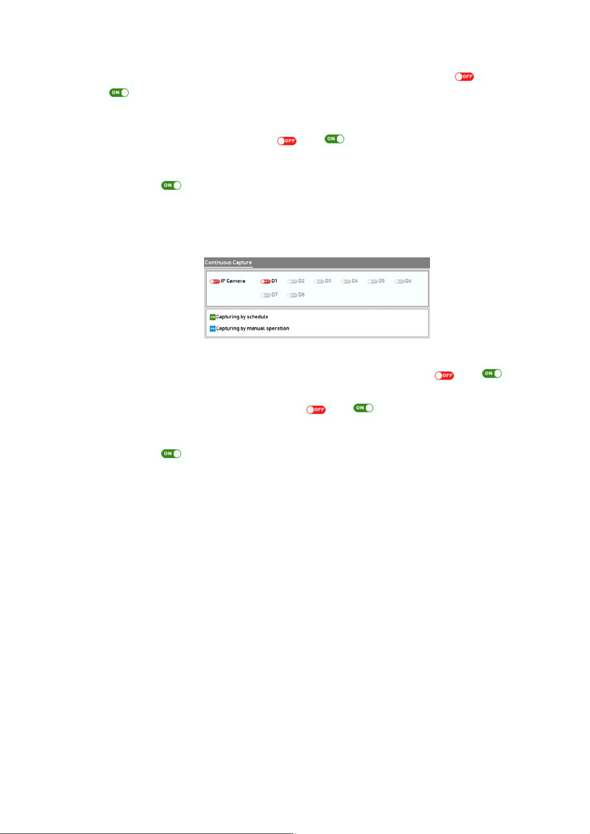
2) Click the <Status> button before the <Camera Number> to change from to
.
3. Disable <Manual Record>.
Click the <Status> button to change from to .
Note:
The Green icon
rebooting, all the manual records enabled will be canceled.
means that the channel is configured for the record schedule. After
4. Enabling and disabling the continuous capture
1) Select <Continuous Capture> on the left bar.
Continuous Capture
2) Click the <Status> button before the camera number to change from to .
3) Disable <Continuous Capture>.
4) Click the <Status> button to change from to .
Note:
The Green icon
rebooting, all the continuous capture will be canceled.
means that the channel is configured for the capture schedule. After
91
Page 92

5.7 Configuring Holiday Recording and Capture
Follow the steps to configure the record or capture schedule on holiday for that year. You may
want to have different plan for recording and capture on holiday.
Steps:
1. Enter the <Record Setting> interface: Menu > Record > Holiday
Holiday Settings
2. Enable <Edit Holiday Schedule>.
1) Click to enter the <Edit> interface.
Edit Holiday Settings
2) Check the checkbox after <Enable Holiday>.
3) Select the <Mode> from the dropdown list.
4) There are three different modes for the date format to configure a holiday schedule.
5) Set the <Start Date> and the <End Date>.
6) Click <Apply> to save the settings.
7) Click <OK> to exit the <Edit> interface.
92
Page 93

3. Enter the <Record/Capture Schedule Settings> interface to edit the <Holiday Recording
Schedule>. See Chapter 5.2 Configuring Recording and Capture Schedule.
93
Page 94

5.8 Configuring Redundant Recording and Capture
Enabling redundant recording and capture, which means saving the record files and captured
pictures not only in the <R/W HDD> but also in the redundant HDD, will effectively enhance the
data safety and reliability.
Steps:
1. Enter the <HDD Information> interface: Menu> HDD
HDD General
2. Select the HDD and click
1) Set the <HDD Property> to <Redundancy>.
2) Click <Apply> to save the settings.
3) Click <OK> to go back to the upper level menu.
Note:
You must set the <Storage Mode> in the <HDD Advanced Settings> to <Group> before you set the
<HDD Property> to <Redundant>. For detailed information, please refer to Chapter
Setting the HDD Property.
status.
to enter the <Local HDD Settings> interface.
14.4.2
There should be at least another HDD which is in <Read/Write>
3. Enter the <Record Settings> interface: Menu> Record> Parameters
1) Select the <Record> tab.
2) Click <More Settings> to enter the following interface.
Record Parameters
3) Select the <Camera> you want to configure in the drop-down list.
4) Check the checkbox of <Redundant Record/Capture>.
5) Click <OK> to save the settings and to go back to the upper level menu.
94
Page 95

Repeat the above steps for configuring other channels.
95
Page 96

5.9 Configuring the HDD Group for Recording and Capture
You can group the HDDs and save the record files and captured pictures in certain <HDD
Group>.
Steps:
1. Enter the <HDD Settings> interface: Menu>HDD
HDD General
2. Select <Advanced> on the left side menu.
Storage Mode
Check whether the <Storage Mode> of the HDD is <Group>. If not, set it to <Group>. For detailed
information, please refer to Chapter 14.4 Managing a HDD Group.
3. Select <General> in the left side menu
4. Click
to enter the <Edit> interface.
5. Configuring an <HDD Group>.
1) Choose a group number for the <HDD Group>.
2) Click <Apply> and then in the pop-up message box, click <Yes> to save your settings.
3) Click <OK> to go back to the upper level menu.
4) Repeat the above steps to configure more <HDD Groups>.
6. Choose the channels which you want to save the record files and captured pictures in the
<HDD Group> to.
1) Select <Advanced> on the left bar.
2) Choose a <Group Number> in the dropdown list of <Record> under <HDD Group>
3) Check the channels you want to save in this group.
4) Click <Apply> to save the settings.
Note:
After having configured the HDD groups, you can configure the <Recording and Capture Settings>
following the procedure provided in Chapter 5.2-5.7.
96
Page 97

5.10 Files Protection
You can lock the recording files or set the <HDD Property> to <Read-only> to protect the
record files from being overwritten.
5.10.1 Locking the Recording Files
Lock File during <Playback>
Steps:
1. Enter the <Playback> interface: Menu> Playback
2. Check the checkbox of channel(s) in the <Channe>l list and then double-click to select a
date on the calendar.
Normal/Smart Playback
3. During <Playback>, click the
Note:
In the <Multi-channel Playback> mode, clicking the
the <Playback> channels.
4. You can click the button to pop up the <File Management> interface. Click the <Locked
File> tab to check and export the locked files.
button to lock the current recording file.
button will lock all the record files related to
97
Page 98

Locked File Management
In the <File Management> interface, you can also click to change it to to unlock the
file and the file is not protected.
Lock File when Export
Steps:
1. Enter the <Export Settings> interface: Menu> Export
Export
2. Select the channels you want to search by checking the checkbox
3. Configure the <Record Type>, <File Type> and <Start/End Time>.
4. Click <Search> to show the results.
Export- Search Result
5. Protect the record files.
98
.
Page 99

1) Find the record files you want to protect and then click to change it to ,
indicating that the file is locked.
Note:
The record files of which the recording is still not completed cannot be locked.
2) Click to change it to to unlock the file; then the file is not protected.
Unlocking Attention
5.10.2 Setting the HDD Property to Read-only
Steps:
1. Enter the <HDD Settings> interface: Menu> HDD
HDD General
2. Click
Note:
To edit the <HDD Property>, you need to set the storage mode of the HDD to <Group>. See
Chapter 14.4 Managing a HDD
3. Set the <HDD Property> to <Read-only>.
4. Click <OK> to save the settings and to go back to the upper level menu.
Note:
‒
‒
‒
to edit the HDD you want to protect.
Group.
You cannot save any files in a read-only HDD. If you want to save files in the HDD, change
the property to <R/W>.
If there is only one HDD and it is set to <Read-only>, then the NVR cannot record any files.
Only <Live View> mode is available.
If you set the HDD to <Read-only> when the NVR is saving files in it, then the file will be
saved in next R/W HDD. If there is only one HDD, then the recording will be stopped.
99
Page 100

6. Playback
6.1 Playing Back Record Files
6.1.1 Instant Playback
Play back the recorded video files of a specific channel in the <Live View> mode. <Channel
Switch> is supported.
Instant <Playback> by channel
Steps:
1. Choose a channel in the <Live View> mode and click
Note:
In the instant <Playback> mode, only record files recorded during the last five minutes on this
channel will be played back.
6.1.2 Playing Back by Normal Search
Playback by Channel:
Enter the <Playback> interface.
Right-click a channel in the <Live View> mode and select <Playback> from the menu, as
shown below.
in the <Quick Setting Toolbar>.
Right-click Menu under Live View
Note:
Pressing numerical buttons will switch the <Playback> to the corresponding channels during the
<Playback> process.
100
 Loading...