

Page 1
HiFi Service Manual
PSW 5000
GLR2300
Zusätzlich erforderliche Unterlagen für den Komplettservice
Additionally required Service Documents for the Complete Service
Service
Manual
Sicherheit
Safety
Materialnr./Part No.
720108000001
Materialnummer/Part Number 720107741500
Änderungen vorbehalten/Subject to alteration
TCC 0506 HH • Prepared in Germany
http://www.grundig.com
NUR FÜR INTERNEN GEBRAUCH
FOR INTERNAL USE ONLY
Page 2
GRUNDIG Service PSW 5000
Es gelten die Vorschriften und Sicherheitshinweise gemäß dem Service Manual "Sicherheit",
Materialnummer 720108000001, sowie zusätzlich die eventuell abweichenden, landesspezifischen Vorschriften!
Inhaltsverzeichnis
Seite
Allgemeiner Teil ................................. 1-2 … 1-3
Allgemeine Hinweise .................................................................... 1-2
Technische Daten ........................................................................ 1-2
Ausbauhinweise ........................................................................... 1-3
Platinenabbildungen
und Schaltpläne ............................... 2-1 … 2-10
Blockschaltplan ............................................................................ 2-1
Verdrahtungsplan ......................................................................... 2-2
Hauptteil:
- Verstärkerplatte ......................................................................... 2-3
- Anschlussplatte .......................................................................... 2-3
- Kanal-Wahlplatte ....................................................................... 2-3
- LED-Platten ............................................................................... 2-3
- Sicherungsplatte ........................................................................ 2-3
Kopfhörerplatte ............................................................................ 2-7
MCU-Platte .................................................................................. 2-8
Sendeeinheit .............................................................................. 2-10
The regulations and safety instructions shall be
valid as provided by the "Safety" Service Manual,
part number 720108000001, as well as the respective national deviations!
Table of Contents
Page
General Section .................................. 1-2 … 1-3
General Notes .............................................................................. 1-2
Technical Data ............................................................................. 1-2
Disassembly Hints ....................................................................... 1-3
Layout of PCBs
and Circuit Diagrams ....................... 2-1 … 2-10
Block Diagram .............................................................................. 2-1
Wiring Diagram ............................................................................ 2-2
Main Part:
- Amplifier Board .......................................................................... 2-3
- Connect Board ........................................................................... 2-3
- CH Select Board ........................................................................ 2-3
- LED Boards ............................................................................... 2-3
- Fuse Board ................................................................................ 2-3
Phone Board ................................................................................ 2-7
MCU Board .................................................................................. 2-8
Transmitter Unit ......................................................................... 2-10
Explosionszeichnungen und
Ersatzteilliste ...................................... 3-1 … 3-2
Explosionszeichnungen ............................................................... 3-1
Ersatzteilliste ................................................................................ 3-2
Allgemeiner Teil
Allgemeine Hinweise
Vor dem Öffnen des Gehäuses zuerst den Netzstecker ziehen!
Achtung: ESD-Vorschriften beachten
Durchführen von Messungen
Bei Messungen mit dem Oszilloskop an Halbleitern sollten Sie nur
Tastköpfe mit 10:1 - Teiler verwenden. Außerdem ist zu beachten,
dass nach vorheriger Messung mit AC-Kopplung der Koppelkondensator des Oszilloskops aufgeladen sein kann. Durch die Entladung
über das Messobjekt können Bauteile beschädigt werden.
Messwerte
Bei den in den Schaltplänen angegebenen Messwerten handelt es
sich um Näherungswerte!
Technische Daten
Funkmodul
Spannungsversorgung .......... Netzadapter DC 9V, 150mA, 50/60Hz
RF-Übertragungsfrequenz .......................................... 863 - 865MHz
Abmessungen B x H x T ...................................... 40 x 137 x 121mm
Gewicht ............................................................................. ca. 0,20kg
Outdoor Lautsprecher
Netzbetrieb .......................... Netzadapter DC 9V, 2000mA, 50/60Hz
Batterien .............................................. 8 x 1,5V, LR 20/AM 1/D-Size
RF-Empfangsfrequenz ................................................863 - 865MHz
Bass-Lautsprecher ................................................................ 150mm
Hochton-Lautsprecher ............................................................ 25mm
Abmessungen B x H x T ................................... 230 x 420 x 210mm
Gewicht ............................................................................. ca. 2,40kg
Exploded Views and
Spare Parts List .................................. 3-1 … 3-2
Exploded Views ........................................................................... 3-1
Spare Parts List ........................................................................... 3-2
General Section
General Notes
Before opening the cabinet disconnect the mains plug!
Attention: Observe the ESD safety regulations
Carrying out Measurements
When making measurements on semi-conductors with an oscilloscope, ensure that the test probe is set to 10:1 dividing factor. If the
previous measurement was made on AC input, please note that the
coupling capacitor in the oscilloscope will be charged. Discharge via
the item being checked can damage the components.
Measured Values
The measured values given in the circuit diagrams are approximates!
Technical Data
Wireless Module
Power supply ..................... Mains adapter DC 9V, 150mA, 50/60Hz
RF transmission frequency ......................................... 863 - 865Mhz
Dimensions W x H x D ......................................... 40 x 137 x 121mm
Weight: .......................................................................approx. 0.20kg
Outdoor Loudspeaker
Mains operation ............... Mains adapter DC 9V, 2000mA, 50/60Hz
Batteries .............................................. 8 x 1.5V, LR 20/AM 1/D-Size
RF reception frequency ............................................... 863 - 865MHz
Bass Speaker ........................................................................ 150mm
Tweeter ................................................................................... 25mm
Dimensions W x H x D ....................................... 230 x 420 x 210mm
Weight ........................................................................approx. 2.40kg
1 - 2
Page 3
GRUNDIG Service PSW 5000
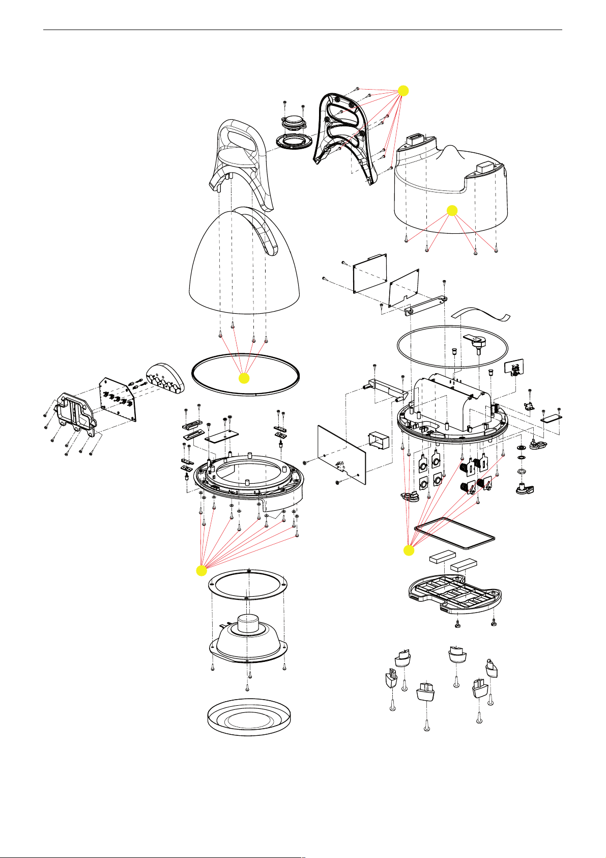
Ausbauhinweise / Disassembly Hints
Demontagereihenfolge / Dismounting Sequence: A, B, C, D, E
E
B
C
D
A
Leitungsverlegung
Bevor Sie die Leitungen und insbesondere die Masseleitungen lösen,
muss die Leitungsverlegung zu den einzelnen Baugruppen beachtet
werden.
Nach erfolgter Reparatur ist es notwendig, die Leitungsführung wieder
in den werkseitigen Zustand zu versetzen um evtl. spätere Ausfälle
oder Störungen zu vermeiden.
Wiring
Before disconnecting any leads and especially the earth connecting
leads observe the way they are routed to the individual assemblies.
On completion of the repairs the leads must be laid out as originally
fitted at the factory to avoid later failures or disturbances.
1 - 3
Page 4
Platinenabbildungen und Schaltpläne / Layout of PCBs and Circuit Diagrams
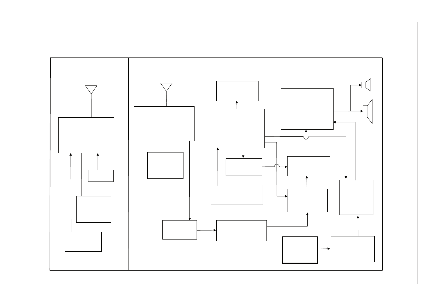
S1 ~ S5
FUNCTION KEY
Q206~209
SPK
RELAY
CIRCUIT
J201
DC 12V
2.5A
Q214~Q216
X’ BASS
RECEIVER
MODULE
IC 101
MCU
IC203
VOLUME
CONTROL
SPK2
SPK1
Q201 ~ Q204
POWER AMP.
IC201 202
PRE. AMP.
J202
AUX IN
IC 204 ,Q211
DC
CONNECTOR
LED 201 202
BACK LIGHT
SW201
CHANNEL
SELECT
DCJ 401
9V 100mA
TRANSMITTER
MODULE
SW401
CHANNEL
SELECT
AF IN
TRANSMITTER UNIT
RECEIER
UNIT
Q212,Q213
MUTING
Blockschaltplan / Block Diagram
GRUNDIG Service PSW 5000
2 - 1
Page 5
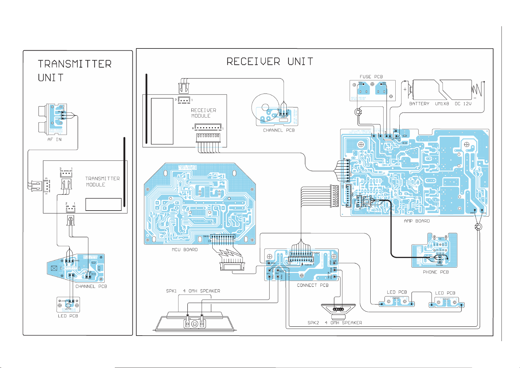
Verdrahtungsplan / Wiring Diagram
2 - 2
GRUNDIG Service PSW 5000
Page 6

R216
4K7
C228
4u7
R220
22K
R223
12K
C231
47P
R215
47K
R219
47K
R211
390
R212
390
C233
100n
+
C232
22u
+
C219
22u/16V
+
C220
22u/16V
R224
5K6
R222
10K
C221
6n8
C223
47n
C224
47n
C222 6n8
R213
47K
C225
330P
R209
1K5
SKP1
4 Ohm SPK
C227
1n
R214
43K
C246
220u
1
2
3
4
5
6
7
89
10
11
12
13
14
15
16
IC203
TA9260
R232 10K
R231 10K
R230
10K
C247
100n
C243
***
R236
27K
+
C266
100u/25V(LESR)
D212
MBRD340
R240
27K
C250
10u
R265
100K
R237
6K8
R238
12K
C249 1n8
R239
2K2
C248
2n7
R233
***
R234
***
C244
***
R235
***
C245
***
C240
1u
R226
1K
R241
4K7
LED202
Reflector light(blue)
Connect Board
16V
R264
27K
R243
33K
1
2
3
4
5
6
7
8
CN203A
1
2
3
4
5
6
7
8
CN203
1
1
2
2
3
3
4
4
SW201
1P3T
CH. Select
ch1
ch2
ch3
AF Out
8V5
LED201
Receive module
5
6
7
4
IC202B
NJM4560(O/AMP)
3
2
1
8
IC202A
NJM4560(O/AMP)
R228
47
16V
Q207
9014/C
C251
100n
R217
18K
Q213
9014C
C242
4u7
R225
18K
R218
4K7
R244
27K
SKP2
4 Ohm SPK
L501
0.3mH
C501
4u7/NP
1
2
3
4
5
6
7
8
9
CN201
9P/2mm WF
16V
back-light sw
4~12V
Gnd
STB
DATA
CLK
SYS on
Mute
12V
R227
56
C234
47u/16V
1
2
3
CN204A
2p/2.5mm
1
2
3
CN204
2p/2.5mm
TO Key PCB
P503
P506
P505
P504
R279
220K
Q214
9014C
C235
1u
R278
22K
C236
22n
R280
47K
R281
100
Q215
9014C
R283
680
R282
4K7
C238
47u/16V
R276
8K2
Q216
9014C
R277
82K
X'Bass
C237
1u
R275
8K2
P502
PAD
P501
PAD
R503
470
P507
PAD
P508
PAD
1
2
3
4
5
6
7
8
9
CN201A
9P/2mm L=350mm
1
2
3
4
5
6
7
8
9
10
CN201B
10P/2mm WF
16V
4~12V
Gnd
STB
DATA
CLK
SYS on
Mute
X'Bass
1
2
3
4
5
6
7
8 9
IC201
ZXCD1000
Mute
12V
C241
1n2
C230
47u
C502
4u7/NP
R502
18 ohm/1W
R501
0.5ohm/1W
R252
47K
R253
68
R242
6K8
Q212
9014C
R254
100K
R256
100K
C252
0.1u
R262
100K
Q210
4N035
R268
56K
R270
***
C253
1n
2
1
3
VR201
200K(B)
R273
180K
R274
82K
R284
68
C226
100u/16V
D215
1SS355
D216
1SS355
1
2
3
4
CN405
3P/2MM WF
L205
3TX2
C503
100n
Oscillator &
Ramp Generator
Internal 5V5
Internal 9V
PWM
ZXCD1000
Comp A
PWM
Comp B
PreDriver
PreDriver
O/P
Driver
O/P
Driver
Audio A
Audio B
V
CC
Cosc
Out A
Out B
5V5
9VB
9VA
Triangle B
Triangle A
Osc B
Osc A
Dist
Gnd
1
2354 6 7
8
9
10
1112
13
14
15
16
Osc
Buffers
GRUNDIG Service PSW 5000
Hauptteil / Main Part
Verstärkerplatte, Anschlussplatte, Kanal-Wahlplatte, LED-Platten, Sicherungsplatte
Amplifier Board, Connect Board, CH Select Board, LED Boards, Fuse Board
2 - 3
Page 7

GRUNDIG Service PSW 5000
5002-voN-12
+
C219
22u/16V
+
C220
22u/16V
C221
6n8
C213
100n
C214
22u
C223
47n
C224
47n
C218
100n
C216
100u/16V
C217
100n
C215
100u/16V
C209
1u/1206
C210
1u/1206
D203
1SS355
R203
47K
R204
75
D204
1SS355
D201
1SS355
R202
75
D202
1SS355
R201
47K
L201
20uH
C203
0.47u/25V(MT)
C211
1u/1206
C212
1u/1206
R207
47K
R208
75
D208 1SS355
R206
75
D206
1SS355
R205
47K
L202
20uH
C205
1u/25V(MT)
C208
0.47u/25V(MT)
D207
1SS355
D205
1SS355
330P
1K5
R263
1.0 Ohm/5W
C202
0.47u/25V(MT)
C201
2200u/25V(LESR)
1
16
+
C266
100u/25V(LESR)
D212
MBRD340
L203
10uH/4A
1
2
3
45
6
7
8
IC204
LM3478
C250
10u
R265
100K
R259
10K
R258
100K
R261
0.025
C265
10n
R257
15K
R260
1K
R241
4K7
R248
0.5
16V
Batt. 12V
DCJ 9V
Q211
9014/C
R267
4.7/0.25W
Q208
8550/C
Q209
9014C
R246
680
R264
27K
C263
100n
R266
39K
R245
47K
R243
33K
C262
100u/25V(LESR)
C264
22n
1
2
3
Q203
4P035
2
1
3
Q202
4N035
2
1
3
Q204
4N035
16V
D209
1N4148
Q207
9014/C
R250
68K
C260
47u
R249
68K
C251
100n
VCC 14V
C258
20n
R247
10K
R244
27K
C501
4u7/NP
R251
18K
(ZXFN1000)
(ZXFN1000)
1
2
3
Q201
4P035
R210
180
12V
R272
560
P502
PAD
P501
PAD
SPKB
PAD
SPKA
PAD
1
2
3
4
5
6
7
8 9
10
11
12
13
14
15
16
IC201
ZXCD1000
12V
C502
4u7/NP
RLY201
RELAY SPDT
D210
1N4148
C204
1u/25V(MT)
R229
33
R252
47K
R253
68
2
1
3
Q210
4N035
Q206
9015/C
R268
56K
R270
***
J201
DCJ 2.5mm
UM1x 8
P201
BAT+
P202
BAT-
2
1
3
VR201
200K(B)
Q218
9014/C
R273
180K
R284
68
R285
150K
R286
56K
D215
1SS355
D216
1SS355
C239
47u
R287
39K
F101
T 2.5A L250V
P101P102
C244
4n7
L204
3TX2
L205
3TX2
Hauptteil / Main Part
Verstärkerplatte, Anschlussplatte, Kanal-Wahlplatte, LED-Platten, Sicherungsplatte
Amplifier Board, Connect Board, CH Select Board, LED Boards, Fuse Board
2 - 4
Page 8

Verstärkerplatte / Amplifier Board
Sicht auf Bestückungsseite / View on Component Side
2 - 5
GRUNDIG Service PSW 5000
Page 9

Verstärkerplatte / Amplifier Board
Sicht auf Lötseite / View on Solder Side
2 - 6
GRUNDIG Service PSW 5000
Page 10

GRUNDIG Service PSW 5000
5
1
4
2
3
J202A
STJ 5P/2P2T
11
10 9
J202B
STJ 5P/2P2T
R288 10K
R289
10K
R292
4K7
R290
1K5
C268
1n
1
2
3
4
CN405A
3P/2MM
FROM MODULE AF
TO AF IN
8
7 6
J202C
STJ 5P/2P2T
Anschlussplatte / Connect Board
Kanal-Wahlplatte / CH Select Board Sicherungsplatte / Fuse Board
LED-Platten / LED Boards
Kopfhörerplatte / Phone Board
Sicht auf Bestückungsseiten / View on Component Sides
2 - 7
Page 11

5002
-vo
N-12
S1
KEY
S5
KEY
S4
KEY
S3
KEY
S2
KEY
R123
10K
R122
10K
R124
10K
R125
10K
ST-BY
VOL+
VOL-
X'BASS
BACK-LIGHT
R102
10K
D102
IN4148
R120
10K
R118
10K
X101
4MHz
C101
22P
C102
22P
VDD
R115
10K
R113
10K
R114
10K
R108
220K
Q103
9014/C
R106
150K
R103
10K
R104
100KH-R
C106
470u/16V
Q102
9014/C
R107
15K
Q101
9012/H
C107
20n
R105
8K2
Q104
9014/C
Q105
9014/C
R121
47K
R117
47K
R119
100
LED1
Blue
LED2
green
R116
100
Power on
X'Bass
R109
100
5V
R110
47K
Mute
back-light
sys on
x'bass
16V(NIL)
back-light sw
4~12V
Gnd
STB
STB
DATA
DATA
CLK
CLK
SYS on
Mute
1
2
3
4
5
6
7
8
910
11
12
13
14
15
16
17
18
IC101
T-0461
1
2
3
4
5
6
7
8
9
10
CN101A
10PINS
R126
390K
Q106
9014/C
R127
150K
R271
1K
R129
2K7
R130
270
C105
47u
C103
20n
X'bass
R131
4K7
R132
100K
R133
100K
R134
100K
JR101
JR
JP101jp
JR104JR
JP103JP
JP104JP
JP105JP
C104
100u
D101
IN4148
R135
22K
Q108
9012/H
D103
IN4148
C108
47u
JR102
JR
JR103JR
5V
JP102JP
JR105JR
JP107
JP
JP108JP
R136
470K
Q107
9014/C
R138
2M7
R137
100K
JP109JP
2 - 8
MCU-Platte / MCU Section
GRUNDIG Service PSW 5000
Page 12

GRUNDIG Service PSW 5000
MCU-Platte / MCU Section
Sicht auf Bestückungsseite / View on Component Side
Sicht auf Lötseite / View on Solder Side
2 - 9
Page 13

GRUNDIG Service PSW 5000
9V/100mA Adapter
AF IN
Transmit module
DCJ401
2mm
CH. Select
1
2
3
CN403A
AFin
1
2
3
CN403
AFout
1
2
3
CN401A
3P
1
2
3
CN401
3P
v+
Gnd
center
ch1
ch2
ch3
OFF
1
2
CN402A
1
2
CN402
2p/2.5mm
LED401
3mm
(blue)
R404
22K
1
2
CN404A
2P/2.5mm
1
2
CN404
2P/2.5mm
1
2
3
4
5
6
7
8
9
10
SW401
4P4TD
Gnd
SK301
RCA Socket
R402
22K
R401
22K
R403
18K
R405
33
Sendeeinheit / Transmitter Unit
Kanal-Wahlplatte / CH Select Board
Sicht auf Bestückungsseite / View on Component Side
RCA-Buchsenplatte / RCA Socket Board
Sicht auf Bestückungsseite /
View on Component Side
LED-Platte / LED Board
Sicht auf Bestückungsseite /
View on Component Side
Sicht auf Lötseite /
View on Solder Side
2 - 10
Page 14

3 - 1
GRUNDIG Service PSW 5000
Explosionszeichnungen und Ersatzteilliste
Exploded Views and Spare Parts List
Page 15

Ersatzteilliste
Spare Parts List
NUR FÜR INTERNEN GEBRAUCH
NUR FÜR INTERNEN GEBRAUCH
FOR INTERNAL USE ONLY
FOR INTERNAL USE ONLY
GRUNDIG Service PSW 5000
ǵ
HIFI
3 - 2
5 / 2006
POS. NR. ABB. MATERIAL-NR. ANZ. BEZEICHNUNG DESCRIPTION
POS. NO. FIG. PART NUMBER QTY.
GLR2300 PSW 5000 WHITE/GREEN PSW 5000 WHITE/GREEN
0001.000 759540318200 GRIFF RUECKTEIL HANDLE BACK
0002.000 759540318300 GRIFF VORDERTEIL HANDLE FRONT
0003.000 759540318400 HOCHTONLAUTSPRECHER TWEETER
0004.000 759540318500 GITTER HOCHTONLAUTSPRECHER GRILLE TWEETER
0005.000 759540396500 LAUTSPRECHERGEHAEUSE OBEN LOUDSPEAKER HOUSING TOP
0006.000 759540318700 DICHTUNG BASSLAUTSPRECHER GASKET SUBWOOFER
0007.000 759540318800 BEDIENTASTEN GUMMI KEY PAD RUBBER
0010.000 759540318900 SCHALTER TAKT TACT SWITCH
0023.000 759540319000 DICHTUNG BATTERIEFACH GASKET BATTERIE DOOR
0024.000 759540319100 BUCHSENABDICHTUNG JACK GASKET
0029.000 759540319200 KANALWAEHLKNOPF KNOB CHANNEL SELECTOR
0032.000 759540319300 DICHTUNG AUX-BUCHSE GASKET AUX-JACK
0036.000 759540319400 BATTERIEGEHAEUSE BATTERY HOUSING
0040.000 759540319500 DREHSCHALTER ROTARY SWITCH
0044.000 759540319600 HF-MODUL RF-BOARD
0046.000 759540319700 DICHTUNG BATTERIEGEHAEUSE GASKET BATTERY HOUSING
0049.000 759540319800 AUDIO MODUL AUDIO BOARD
0100.000 759540318600 GEHAEUSE MIT BASSLAUTSPRECHER CABINET WITH SUBWOOFER ASSY
0101.000 759540319900 TRANSMITTER TRANSMITTER
0102.000 S 759540370100 NETZADAPTER 230V / 9V 150MA POWER ADAPTOR 230V / 9V 150MA
0103.000 S 759540370200 NETZADAPTER 230V / 9V 2000MA POWER ADAPTOR 230V / 9V 2000MA
0110.000 759540396600 KARTON CARTON
720114065000 BEDIENUNGSANLEITUNG INSTRUCTION MANUAL
720107741500 SERVICE MANUAL D/GB SERVICE MANUAL D/GB
d©
KEIN E-TEIL NO SPARE PART
D,GB,F,I,P,E,NL,PL,DK,S,FIN,TR D,GB,F,I,P,E,NL,PL,DK,S,FIN,TR
BESTELL-NR. / ORDER NO.: GLR2300
PSW 5000
Es gelten die Vorschriften und Sicherheitshinweise
gemäß dem Service Manual "Sicherheit", Mat.-Nummer 720108000001, sowie zusätzlich die eventuell abweichenden, landesspezifischen Vorschriften!
The regulations and safety instructions shall be valid
!
as provided by the "Safety" Service Manual, part
number 720108000001, as well as the respective
( ! )
national deviations.
ÄNDERUNGEN VORBEHALTEN / SUBJECT TO ALTERATION
 Loading...