

Page 1
TV Service Manual
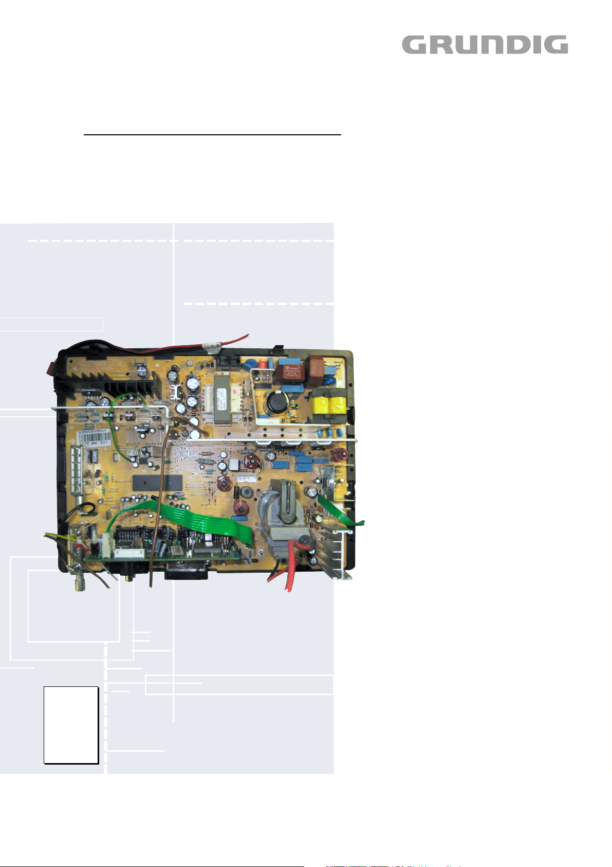
Chassis 22.1
ARCANCE 82 Flat
MFW 82-2410/7 Dolby
GBB4100
ARCANCE 72 Flat
MF 72-2410/7 Top
GBB4300
ARCANCE 70 Flat
MFW 70-2410/7 Dolby
GBB4200
Zusätzlich erforderliche Unterlagen für den Komplettservice
Additionally required Service Documents for the Complete Service
Service
Manual
Sicherheit
Safety
Materialnr./Part No.
720108000000
Materialnummer/Part Number 720100475000
Änderungen vorbehalten/Subject to alteration
H-S43 1003 • Printed in Germany
http://www.grundig.com
Page 2

GRUNDIG Service Chassis 22.1
Es gelten die Vorschriften und Sicherheitshinweise
gemäß dem Service Manual "Sicherheit", Materialnummer 720108000000, sowie zusätzlich die eventuell abweichenden, landesspezifischen Vorschriften!
D
Inhaltsverzeichnis
Seite
Allgemeiner Teil ................................. 1-2…1-11
Allgemeine Hinweise .................................................................... 1-2
Sicherheits-Hinweise ................................................................... 1-3
Service-Hinweise ......................................................................... 1-3
Technische Daten ........................................................................ 1-4
Bedienhinweise ............................................................................ 1-5
Service- und Sonderfunktionen (Softwareversion 11) ................. 1-7
Abgleich ................................................ 2-1…2-3
Platinenabbildungen
und Schaltpläne ................................. 3-1…3-15
Blockschaltplan ............................................................................ 3-1
Variantenliste ............................................................................... 3-1
Netzteil ......................................................................................... 3-2
Horizontal-Ablenkung ................................................................... 3-2
Vertikal-Ablenkung ....................................................................... 3-2
Chassisplatte ............................................................................... 3-3
Hauptschaltplan ........................................................................... 3-7
Tuner ............................................................................................ 3-8
Tuner PIP ..................................................................................... 3-8
Bildrohrplatte ................................................................................ 3-9
Dyn. Fokusierung ....................................................................... 3-10
Audiobuchsen-Platte .................................................................. 3-10
Tasten-Platte .............................................................................. 3-10
Feature-Platte ............................................................................ 3-10
Oszillogramme ........................................................................... 3-14
The regulations and safety instructions shall be valid
as provided by the "Safety" Service Manual, part
number 720108000000, as well as the respective
national deviations.
GB
Table of Contents
Page
General Section .................................. 1-2…1-11
General Notes .............................................................................. 1-2
Safety Advices ............................................................................. 1-3
Service Notes ............................................................................... 1-3
Technical Data ............................................................................. 1-4
Operating Hints ............................................................................ 1-6
Service and Special Functions (Software version 11) ................. 1-7
Alignment.............................................. 2-4…2-6
Layout of the PCBs
and Circuit Diagrams .........................3-1…3-15
Block Diagram .............................................................................. 3-1
Variant List ................................................................................... 3-1
Mains Section .............................................................................. 3-2
Horizontal Deflection .................................................................... 3-2
Vertical Deflection ........................................................................ 3-2
Chassis Board .............................................................................. 3-3
Main Circuit Diagram ................................................................... 3-7
Tuner ............................................................................................ 3-8
Tuner PIP ..................................................................................... 3-8
CRT Panel ................................................................................... 3-9
Dynamic Focus PCB .................................................................. 3-10
Audio Socket Board ................................................................... 3-10
Keyboard .................................................................................... 3-10
Feature Module .......................................................................... 3-10
Oscillograms .............................................................................. 3-14
Ersatzteillisten ...................................... 4-1…4-4
Allgemeiner Teil
Allgemeine Hinweise
Vor dem Öffnen des Gehäuses zuerst den Netzstecker ziehen!
Leitungsverlegung
Bevor Sie die Leitungen und insbesondere die Masseleitungen lösen,
muss die Leitungsverlegung zu den einzelnen Baugruppen wie z.B.
Chassis, Netzschalterplatte, Bedieneinheit, Bildrohrplatte, Ablenkeinheit, Lautsprecher usw. beachtet werden.
Nach erfolgter Reparatur ist es notwendig, die Leitungsführung wieder
in den werkseitigen Zustand zu versetzen um evtl. spätere Ausfälle
oder Störungen zu vermeiden.
Software-Versionsnummer
Die Anzeige der Software-Versionsnummer ist im Kapitel "Serviceund Sonderfunktionen" auf Seite 1-11 beschrieben.
Austausch der Feature-Platte
Nach Austausch der Feature-Platte müssen alle Einstellungen im
Service Mode nach Tabelle „Grundeinstellwerte“ (Punkt 1 im Kapitel
"Service- und Sonderfunktionen" auf Seite 1-7) eingestellt werden.
Spare Parts List .................................... 4-1…4-4
General Section
General Notes
Before opening the cabinet disconnect the mains plug!
Wiring
Before disconnecting any leads and especially the earth connecting
leads observe the way they are routed to the individual assemblies like
the chassis, mains switch panel, keyboard control panel, picture tube
panel, deflection unit, loudspeaker and so on.
On completion of the repairs the leads must be laid out as originally
fitted at the factory to avoid later failures or disturbances.
Software Version Number
The indication of the Software version number is described in chapter
"Service and Special Functions" on page 1-11.
Change of the Feature Board
After changing the feature board all settings in the service mode must
be done according to the table „Basic Settings“ (point 1 in chapter
"Service and Special Functions" on page 1-7).
1 - 2
Page 3

GRUNDIG Service Chassis 22.1
Sicherheits-Hinweise
Die in den Fernsehgeräten auftretende Röntgenstrahlung entspricht
den Bestimmungen der Physikalisch-Technischen Bundesanstalt vom
8. Januar 1987.
Die Hochspannung für die Bildröhre und die damit auftretende
Röntgenstrahlung ist abhängig von der exakten Einstellung der Netzteilspannung +B.
Nach jeder Reparatur im Netzteil oder in der Horizontalablenkung ist
die Hochspannung zu messen und gegebenenfalls einzustellen.
Schutzschaltungen im Gerät dürfen nur kurzzeitig außer Betrieb gesetzt werden, um Folgeschäden am Chassis oder an der Bildröhre zu
vermeiden.
Beim Austausch der Bildröhre dürfen nur die in den Ersatzteillisten
vorgeschriebenen Typen verwendet werden.
D
Service-Hinweise
Chassisausbau
Bevor Sie die Chassis-Verbindungsleitungen lösen, muss die Leitungsverlegung zu den einzelnen Baugruppen wie Netzschalterplatte, Bedieneinheit, Bildrohrplatte, Ablenkeinheit oder Lautsprecher beachtet werden.
Nach erfolgter Reparatur ist es notwendig, die Leitungsführung wieder
in den werkseitigen Zustand zu versetzen, um eventuell spätere
Ausfälle oder Störungen zu vermeiden.
Safety Advices
The X-radiation developing in the sets conforms to the X-radiation
Regulations (January 8, 1987), issued by the Physikalisch-Technische Bundesanstalt (federal physiotechnical institution).
The high tension for the picture tube and thus the developing Xradiation depends on the precise adjustment of the +B power supply.
After every repair of the power supply unit or the horizontal deflection
stage it is imperative that the EHT for the picture tube is checked and
re-adjusted if necessary.
To avoid consequential damages to the chassis or the picture tube
the integrated protective circuits are allowed to be put out of operation
only for a short time.
When replacing the picture tube use only the types specified in the
spare parts lists.
Cable dereseau
Ces appareils ne peuvent être utilisés qu ' avec un cable de connecion
original de réseau avec bobine antiparasite intégré dans la fiche de
secteur. Ce câble de réseau empêche des perturbations de réseau et
est partie de l'autorisation d'appareil. Si nécessaire commandez
uniquement le cable de réseau selon la liste de pièces détachées.
Netzkabel
Diese Geräte dürfen nur mit dem Original-Netzanschlusskabel mit
integrierter Entstördrossel betrieben werden. Dieses Netzkabel verhindert Störungen aus dem Netz und ist Bestandteil der Gerätezulassung. Im Ersatzfall bestellen Sie bitte ausschließlich das Netzkabel laut Ersatzteilliste.
GB
Service Notes
Disassembly of the chassis
Before disconnecting the chassis connecting leads observe the way
they are routed to the individual assemblies like the mains switch
panel, keyboard control panel, picture tube panel, deflection unit or
loudspeaker.
On completion of the repairs the leads must be laid out as originally
fitted at the factory to avoid later failures or disturbances.
Mains cable
The TV receiver must only be operated with an original mains connecting
cable with an interference suppressor choke integrated in the mains
plug.This mains cable prevents interference from the mains supply and
is part of the product approval. For replacement please order exclusively
the mains connecting cable specified in the spare parts list.
F
Information pour la maintenance
Dèmontage de chassis
Avant de défaire les connecteurs du châssis princip, il y a lieu de
repérer auparavant les liaisons correspondant à chaque platine comme
par exemple le C.I. Inter secteur, le C.I. Commande, le C.I. Tube, le
bloc déviation ou les haut-parleurs.
A la fin de l'intervention, les connexions doivent être remises dans leur
position d'origine afin d'éviter par après d'éventuelles défaillances ou
perturbations.
I
Nota di servizio
Smontaggio del telaio
Prima di sfilare i cavi di collegamneto col telaio è necessario osservare
la disposizione originaria degli stessi verso le singole parti come la
piastra alimentazione, l'unità comandi, la piastra cinescopio, il giogo o
l'altoparlante.
Dopo la riparazione è necessario che gli ancoraggi e le guide
garantiscano la disposizione dei cavi analogamente a quella data in
fabrica e ciò per evitare disturbi o danni nel tempo.
Cavo rete
Gli apperechi devono essere messi in funzioni solo con il cavo originale
il colle gamento di rete e la sua spina di rete deve essere munita di una
bombina d´induttanza. In causa di sostituzione ordinate solo il cavo di
alimentatore che corrésponde alla lista degli accessori.
E
Nota de servicio
Desmontaje del chassis
Antes de desconectar las conecciones del Chassis hay que observar
la dirección de dichas conecciones a los distintos grupos de construcción
como la placa de conmutación de red, unidad de control, placa del
zócalo del tubo de imagen, unidad de deflección o altavoces.
Después de haber realizado la reparación y para evitar fallos o
pertubaciones posteriores es necesario reponer las conecciones tal
como fueron instaladas originalmente en fabrica.
Cable de red
El aparato solo se puede usar con el cable de red original con choque
antiparásito integrado en el enchufe de red. Este cable de red evita
perturbaciones de la red y es parte de la autorización del aparato. En
caso necesario puede pedir el cable de red según lista de piezas de
repuestos.
1 - 3
Page 4
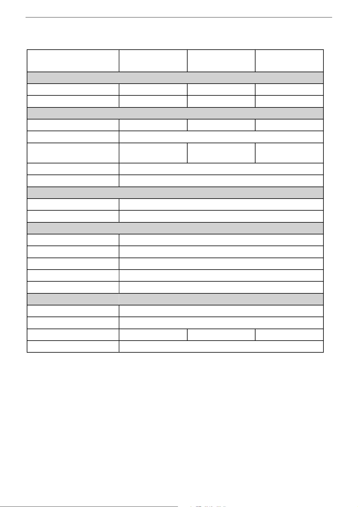
Technische Daten / Technical Data
Chassis 22.1GRUNDIG Service
Bildröhre / Picture Tube
Sichtbares Bild
Visible picture
Bildröhre
Picture tube
Elektronik / Electronic
Programmspeicherplätze
Programme positions
Tuner
TV-Normen
TV-Standards
Videotext
Teletext
Musikleistung
Music power
Anschlüsse seitlich / Connections Side
Kopfhörer
Headphones
Cinch-AV/Hosiden
Anschlüsse Rückwand / Connections Rear Panel
Euro AV 1 (schwarz/black)
Euro AV 2 (schwarz/black)
Euro AV 3 (schwarz/black)
Audio Ausgang Cinch
Audio Output Cinch
Antenne
Antenna
Netzteil / Mains Stage
Netzspannung (Regelbereich)
Mains voltage (variable)
Netzfrequenz
Mains frequency
Leistungsaufnahme
Power consumption
Standby
ARCANCE 82 Flat
MFW 82-2410/7 Dolby
Chassis 22.1
76cm 68cm 66cm
82cm (32") 16:9 Real Flat
Panasonic
99 + 4 AV
PLL Frequenz Synthesizer Tuning UHF/VHF / PLL frequency synthesizer tuning UHF/VHF
BG, DK/K´, PAL, SECAM, NTSC 4,43MHz,
über/via AV: NTSC 3,58MHz,
A2 für/for B/G/D/K,
Nicam 5,85MHz (BG, L) +6
1 x FBAS Video/in (AV 4 Position) / 1 x CCVS Video/in (AV 4 Position)
FBAS Ein-/Ausgang, RGB Eingang, Audio Ein-/Ausgang
CCVS in-/output, RGB input, audio in-/output
FBAS Ein-/Ausgang, RGB Eingang, S-Video Eingang, Audio Ein-/Ausgang
CCVS in-/output, RGB input, S-Video input, audio in-/output
ca. 200W ca. 185W ca. 185W
ARCANCE 72 Flat
MF 72-2410/7 Top
Chassis 22.1
72cm (29") 4:3 Real Flat
Samsung
99 + 4 AV
BG, DK/K´, PAL, SECAM, NTSC 4,43MHz,
über/via AV: NTSC 3,58MHz,
A2 für/for B/G/D/K, Nicam 5,85MHz
512-Seiten-Speicher
512 pages memory
Stereo 30W
3,5mm Klinkenbuchse
3.5mm jack
2 x Audio/in, S-Video/in (AV 4-S Position)
FBAS Ein-/Ausgang, Audio Ein-/Ausgang
CCVS in-/output, audio in-/output
Line out
Koaxial-Buchse DIN 45325
Coaxial socket acc. DIN 45325
230V ±15%
50 / 60Hz
ca. 5W
ARCANCE 70 Flat
MFW 70-2410/7 Dolby
Chassis 22.1
70cm (28") 16:9 Real Flat
Samsung
99 + 4 AV
BG, DK/K´, PAL, SECAM, NTSC 4,43MHz,
über/via AV: NTSC 3,58MHz,
A2 für/for B/G/D/K,
Nicam 5,85MHz (BG, L) +6
1 - 4
Page 5
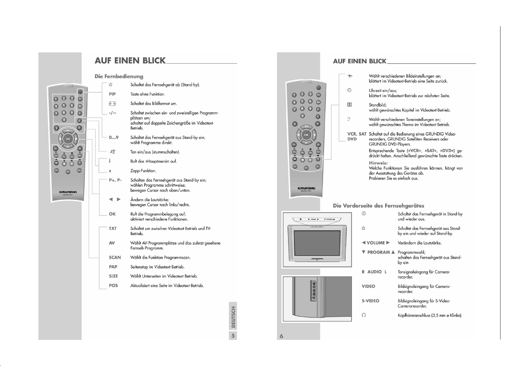
Bedienhinweise Dieses Kapitel enthält Auszüge aus der Bedienungsanleitung.
Weitergehende Informationen entnehmen Sie bitte der gerätespezifischen Bedienungsanleitung, deren Materialnummer Sie in der entsprechenden Ersatzteilliste finden.
1 - 5
Chassis 22.1GRUNDIG Service
Page 6
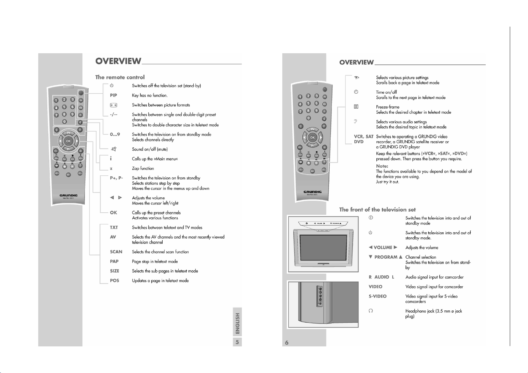
Operating Hints This chapter contains excerpts from the operating instructions.
For further particulars please refer to the appropriate user instructions the part number of which is indicated in the relevant spare parts list.
1 - 6
Chassis 22.1GRUNDIG Service
Page 7
Chassis 22.1GRUNDIG Service
Service- und Sonderfunktionen
Service Mode aktivieren: Taste "Ǻ" (Hauptmenü) –> Service Code
"8500".
Service Mode beenden: Taste "TXT" drücken.
1. Grundeinstellwerte
Nachfolgende Tabelle zeigt alle typenbezogenen Grundeinstellungen im Service Mode. Alle mit * gekennzeichneten Werte müssen
zusätzlich nach Abgleich (Seite 2-1) einstellen werden.
Menü
Menu
Ƕ oder/or ǵ
OPTIONS
Menüpunkt
Point of Menu
Ƕ oder/or ǵ
STANDBY
SCART 3
FRONT AV
TELETEXT
TXT TABLE
LANGUAGE
CRT
PIP
MAIN TUNER
PIP TUNER
SVM
DEGAUSS
(Softwareversion 11)
Einstellung
Adjustment
Ǹ oder/or Ƿ
3 oder/or 1
6 oder/or 4
CUSTOMER MODE
FACTORY MODE
AVAILABLE
NOT AVAILABLE
CVBS & SVHS AVAILABLE
ONLY CVBS AVAILABLE
ONLY SVHS AVAILABLE
NOT AVAILABLE
FASTEXT & TOPTEXT
DEFAULT TEXT
FASTEXT
TOPTEXT
AUTO
WEST
EAST
GREEC
CYRILLIC
ARABIC
FARSI
HEBREW
A
B
C
D
16:9
4:3
AVAILABLE
NOT AVAILABLE
PHILIPS
PANASONIC DB2G3
TEMIC
PANASONIC D44G3
SHARP OR ALPS
PHILIPS
PANASONIC DB2G3
TEMIC
PANASONIC D44G3
SHARP OR ALPS
VIA MENU
OFF
ON
X Second
NOT AVAILABLE
Service and Special Funktions
Start of the Service Mode: Via "Ǻ" (Main Menu) –> Service Code
"8500".
End the Service Mode: Press button "TXT".
1. Basic Settings
The following table shows all type specific basic settings in the service mode. In addition all values marked with * must be adjusted according to adjustment (page 2-4).
Hinweis
Hint
512p level 1.5
1024p level 1.5
2048p level 2.5
Vesrchiedene Sprachkombinationen
Different language combination
eingebauten Tuner wählen
select used tuner
eingebauten Tuner wählen
select used tuner
(Software version 11)
Gerät / Type of Set
ARCANCE 82 Flat
MFW 82-2410/7 Dolby
ARCANCE 72 Flat
MF 72-2410/7 Top
ARCANCE 70 Flat
MFW 70-2410/7 Dolby
xxx
x
xx
x
xx
xxx
xxx
xxx
xx
x
x
xx
xxx
X=10 X=10 X=10
* Mittelwert / Average Value
** bei Philips Bildröhren A66EAK071X44 und A66EAK075X44 / for Philips CRTs A66EAK071X44 und A66EAK075X44
1 - 7
Page 8
Chassis 22.1GRUNDIG Service
Gerät / Type of Set
Menü
Menu
Ƕ oder/or ǵ
OPTIONS
SOUND OPTIONS
COLORS
Menüpunkt
Point of Menu
Ƕ oder/or ǵ
BLUE BACK
TILT
CURTAIN
LTI
(Luminance Transient
Improvment)
CTI
(Color Transient Improvment)
COMB FILTER
PROTECTION
PANORAMA
STOCK TICKER
TXT SWAP
DEMO MODE
BG
DK
I
L/L’
NICAM
DOLBY VIRTUAL
SUBWOOFER
HEADPHONE
CARRIER MUTE
DYNAMIC BASS
BLUEBACK Y
BLUEBACK U
BLUEBACK V
CURTAIN Y
CURTAIN U
CURTAIN V
MULTIPICTURE Y
MULTIPICTURE U
MULTIPICTURE V
Einstellung
Adjustment
Ǹ oder/or Ƿ
3 oder/or 1
6 oder/or 4
VIA MENU
OFF
ON
AVAILABLE
NOT AVAILABLE
AVAILABLE
NOT AVAILABLE
VIA MENU
OFF
ON
VIA MENU
OFF
ON
VIA MENU
OFF
ON
AVAILABLE
NOT AVAILABLE
AVAILABLE
NOT AVAILABLE
ENABLE
DISABLE
ENABLE
DISABLE
OFF
ON
AVAILABLE
NOT AVAILABLE
AVAILABLE
NOT AVAILABLE
AVAILABLE
NOT AVAILABLE
AVAILABLE
NOT AVAILABLE
AVAILABLE
NOT AVAILABLE
AVAILABLE
NOT AVAILABLE
AVAILABLE
NOT AVAILABLE
AVAILABLE
NOT AVAILABLE
VIA MSP
VIA MICRO
AVAILABLE
NOT AVAILABLE
Zahlenwert/Value
Zahlenwert/Value
Zahlenwert/Value
Zahlenwert/Value
Zahlenwert/Value
Zahlenwert/Value
Zahlenwert/Value
Zahlenwert/Value
Zahlenwert/Value
Hinweis
Hint
ARCANCE 82 Flat
MFW 82-2410/7 Dolby
ARCANCE 72 Flat
MF 72-2410/7 Top
ARCANCE 70 Flat
MFW 70-2410/7 Dolby
xxx
x
x
x
x
x
x
xxx
x
xx
x
xx
Schutzschaltung /Protection Circuit
Nur mit PIP / Only with PIP
ATS reset
0-15
0-15
0-15
0-15
0-15
0-15
0-15
0-15
0-15 000
xxx
x
x
x
x
x
x
x
x
x
x
x
x
x
0
0
3
3
0
0
0
0
1
1
0
0
4
4
0
0
x
x
xx
xx
xx
xx
xx
xx
xx
xx
xx
xx
xx
xx
0
3
0
0
1
0
4
0
* Mittelwert / Average Value
** bei Philips Bildröhren A66EAK071X44 und A66EAK075X44 / for Philips CRTs A66EAK071X44 und A66EAK075X44
1 - 8
Page 9
Chassis 22.1GRUNDIG Service
Gerät / Type of Set
Menü
Menu
Ƕ oder/or ǵ
COLORS
JUST-
IF AD-
MENTS
100Hz GEOMETRY ADJUSTMENT
120Hz GEOMETRY ADJUSTMENT
Menüpunkt
Point of Menu
Ƕ oder/or ǵ
PIP FRAME Y
PIP FRAME U
PIP FRAME V
FRAME Y
FRAME U
FRAME V
AGC 1 VHFIII-UHF
AGC 1 VHFI
AGC 2 VHFIII-UHF
AGC 2 VHFI
VERTICAL AMPLITUDE
VERTICAL ZOOM
VERTICAL SHIFT
LINEARITY
S-CORRECTION
VERTICAL ANGLE
VERTICAL BOW
HORIZONTAL WIDTH
HORIZONTAL SHIFT
TRAPEZE CORRECTION
CUSHION CORRECTION
UPPER CORNER 1
LOWER CORNER 1
UPPER CORNER 2
LOWER CORNER 2
EHT TRESHOLD
EHT TIME CONSTANT
VERTICAL EHT 1
VERTICAL EHT 2
HORIZONTAL EHT 1
HORIZONTAL EHT 2
EHT FTC
EHT P1
EHT P2
TRAPEZE COR. 4:3
CUSHION COR. 4:3
UPPER CORNER 1 4:3
LOWER CORNER 1 4:3
UPPER CORNER 2 4:3
LOWER CORNER 1 4:3
TILT
HOR. OSD POSITION
VER: OSD POSITION
VERTICAL AMPLITUDE
VERTICAL ZOOM
VERTICAL SHIFT
LINEARITY
S-CORRECTION
VERTICAL ANGLE
VERTICAL BOW
HORIZONTAL WIDTH
HORIZONTAL SHIFT
TRAPEZE CORRECTION
CUSHION CORRECTION
UPPER CORNER 1
Einstellung
Adjustment
Ǹ oder/or Ƿ
3 oder/or 1
6 oder/or 4
Zahlenwert/Value
Zahlenwert/Value
Zahlenwert/Value
Zahlenwert/Value
Zahlenwert/Value
Zahlenwert/Value
Zahlenwert/Value
Zahlenwert/Value
Zahlenwert/Value
Zahlenwert/Value
Zahlenwert/Value
Zahlenwert/Value
Zahlenwert/Value
Zahlenwert/Value
Zahlenwert/Value
Zahlenwert/Value
Zahlenwert/Value
Zahlenwert/Value
Zahlenwert/Value
Zahlenwert/Value
Zahlenwert/Value
Zahlenwert/Value
Zahlenwert/Value
Zahlenwert/Value
Zahlenwert/Value
Zahlenwert/Value
Zahlenwert/Value
Zahlenwert/Value
Zahlenwert/Value
Zahlenwert/Value
Zahlenwert/Value
Zahlenwert/Value
Zahlenwert/Value
Zahlenwert/Value
Zahlenwert/Value
Zahlenwert/Value
Zahlenwert/Value
Zahlenwert/Value
Zahlenwert/Value
Zahlenwert/Value
Zahlenwert/Value
Zahlenwert/Value
Zahlenwert/Value
Zahlenwert/Value
Zahlenwert/Value
Zahlenwert/Value
Zahlenwert/Value
Zahlenwert/Value
Zahlenwert/Value
Zahlenwert/Value
Zahlenwert/Value
Zahlenwert/Value
Zahlenwert/Value
Zahlenwert/Value
Zahlenwert/Value
Hinweis
Hint
ARCANCE 82 Flat
0-15 0
0-15
0-15
0-15
0-15
0-15
0-31
0-31
0-31
0-31
Siehe Abgleich S.2-1/see adjustment P.2-420-384*
Siehe Abgleich S.2-1/see adjustment P.2-4
Siehe Abgleich S.2-1/see adjustment P.2-4
Siehe Abgleich S.2-1/see adjustment P.2-4
Siehe Abgleich S.2-1/see adjustment P.2-4
Siehe Abgleich S.2-1/see adjustment P.2-41*-16*
Siehe Abgleich S.2-1/see adjustment P.2-4
Siehe Abgleich S.2-1/see adjustment P.2-4
Siehe Abgleich S.2-1/see adjustment P.2-4
Siehe Abgleich S.2-1/see adjustment P.2-4
Siehe Abgleich S.2-1/see adjustment P.2-4
Siehe Abgleich S.2-1/see adjustment P.2-4
Siehe Abgleich S.2-1/see adjustment P.2-4
Siehe Abgleich S.2-1/see adjustment P.2-450136*
Siehe Abgleich S.2-1/see adjustment P.2-4
Siehe Abgleich S.2-1/see adjustment P.2-4
Siehe Abgleich S.2-1/see adjustment P.2-4 -375*
Siehe Abgleich S.2-1/see adjustment P.2-4
Siehe Abgleich S.2-1/see adjustment P.2-4
Siehe Abgleich S.2-1/see adjustment P.2-4
Siehe Abgleich S.2-1/see adjustment P.2-4
Siehe Abgleich S.2-1/see adjustment P.2-4
Siehe Abgleich S.2-1/see adjustment P.2-4
Siehe Abgleich S.2-1/see adjustment P.2-4 283*
Siehe Abgleich S.2-1/see adjustment P.2-4
Siehe Abgleich S.2-1/see adjustment P.2-4
0
2
0
2
0
15
20
15
200
-2*
-37*
85*
252*
284*
-47
-184*
-4*
54*
74*
45*
200
60
-102
15
-90
-50
2
-20
0
-29
-170
20
45
45
29*
4*
200
-3*
-1*
175*
1*
-6*
255*
-42
-214*
92*
MFW 82-2410/7 Dolby
ARCANCE 72 Flat
MF 72-2410/7 Top
ARCANCE 70 Flat
MFW 70-2410/7 Dolby
00
0
0
2
2
0
0
2
2
0
15015
201520
15
20
-314*20-262*
255
200
-2*
-2*
-40*
-37*
180*
85*
0*
-3*1*6*
255*
225*
278*
273*
-46
-68
-205*
-189*
33*
-9*
39*
114 *
4*
51*
33*
-85*
20040200
60
-9215-102
15
-80
-90
-50
-50
5
02-20
10
-20
-68
-34
-20533-189
-9
394114
51
33
-85
136*
136*
33*5*31*
4*
-275*
-278*
255
200
-6*5*-5*
-1*
125*0*175*
0*
4*
-6*
255*
215*
259*
256*
-19
-45
-210*
-217*
20*
32*
* Mittelwert / Average Value
** bei Philips Bildröhren A66EAK071X44 und A66EAK075X44 / for Philips CRTs A66EAK071X44 und A66EAK075X44
1 - 9
Page 10
Chassis 22.1GRUNDIG Service
Gerät / Type of Set
Menü
Menu
Ƕ oder/or ǵ
120Hz GEOMETRY ADJUSTMENT
VIDEO ADJUSTMENTS
Menüpunkt
Point of Menu
Ƕ oder/or ǵ
LOWER CORNER 1
UPPER CORNER 2
LOWER CORNER 2
EHT TRESHOLD
EHT TIME CONSTANT
VERTICAL EHT 1
VERTICAL EHT 2
HORIZONTAL EHT 1
HORIZONTAL EHT 2
EHT FTC
EHT P1
EHT P2
TRAPEZE COR. 4:3
CUSHION COR. 4:3
UPPER CORNER 1 4:3
LOWER CORNER 1 4:3
UPPER CORNER 2 4:3
LOWER CORNER 1 4:3
TILT
HOR. OSD POSITION
VER: OSD POSITION
R.DRIVE
G.DRIVE
B.DRIVE
R.CUTOFF
G.CUTOFF
B.CUTOFF
BCL GAIN
BCL TRESHOLD
BCL TRESHOLD 16:9
BCL TIME CONSTANT1
BCL TIME CONSTANT2
YC DELAY FOR PAL
YC DELAY FOR SECAM
YC DELAY FOR NTSC
OSD BRIGHTNESS
OSD CONTRAST
TXT BRIGHTNESS
SCREEN ADJ.
SUBCARRIER ADJ.
PWL
TXT CONTRAST
PAT CONTRAST
Einstellung
Adjustment
Ǹ oder/or Ƿ
3 oder/or 1
6 oder/or 4
Zahlenwert/Value
Zahlenwert/Value
Zahlenwert/Value
Zahlenwert/Value
Zahlenwert/Value
Zahlenwert/Value
Zahlenwert/Value
Zahlenwert/Value
Zahlenwert/Value
Zahlenwert/Value
Zahlenwert/Value
Zahlenwert/Value
Zahlenwert/Value
Zahlenwert/Value
Zahlenwert/Value
Zahlenwert/Value
Zahlenwert/Value
Zahlenwert/Value
Zahlenwert/Value
Zahlenwert/Value
Zahlenwert/Value
Zahlenwert/Value
Zahlenwert/Value
Zahlenwert/Value
Zahlenwert/Value
Zahlenwert/Value
Zahlenwert/Value
Zahlenwert/Value
Zahlenwert/Value
Zahlenwert/Value
Zahlenwert/Value
Zahlenwert/Value
Zahlenwert/Value
Zahlenwert/Value
Zahlenwert/Value
Zahlenwert/Value
Zahlenwert/Value
Zahlenwert/Value
Zahlenwert/Value
Zahlenwert/Value
Zahlenwert/Value
Zahlenwert/Value
Zahlenwert/Value
Hinweis
Hint
ARCANCE 82 Flat
Siehe Abgleich S.2-1/see adjustment P.2-4
Siehe Abgleich S.2-1/see adjustment P.2-4
Siehe Abgleich S.2-1/see adjustment P.2-4 -13*
Siehe Abgleich S.2-1/see adjustment P.2-4
Siehe Abgleich S.2-1/see adjustment P.2-4
Siehe Abgleich S.2-1/see adjustment P.2-4 0*
Siehe Abgleich S.2-1/see adjustment P.2-40*
114*
-45*
200
60
-102
15
-90
-50
2
-20
0
-10
-160
72
44
-45
-13
136*
28*
289
225
245
200
200
190
500
315
150
200
0
0
0
0
128
400
0
220
350
300
MFW 82-2410/7 Dolby
ARCANCE 72 Flat
MF 72-2410/7 Top
ARCANCE 70 Flat
MFW 70-2410/7 Dolby
20*
104*
-6*
63*
-23*
-13*
200
200
40
-9260-102
15
-8015-90
-502-50
5
010-20
-20
-16
-45
-201
-217
103032
104
-6663
-13
136*
136*
32*
30*
0*
2640*268
225
225
209
221
279
210
200
200
240
223
500
500
315/
340
330**
50
150
2000200
0
0
0
0
0
0
1280128
400
400
0/
128
-64**
0
0
*
*
220/
220
130**
350/
350
300**
300/
300
250**
* Mittelwert / Average Value
** bei Philips Bildröhren A66EAK071X44 und A66EAK075X44 / for Philips CRTs A66EAK071X44 und A66EAK075X44
1 - 10
Page 11

Chassis 22.1GRUNDIG Service
2. Austausch der Feature-Platte
Nach Austausch der Feature-Platte müssen alle Einstellungen im
Service Mode nach Tabelle "Grundeinstellwerte" (Punkt 1) eingestellt werden.
3. Programmsuchlauf (ATS)
Tasten "
Ǻ" (Hauptmenü) -> Ƕ/ǵ "SETUP" -> "OK" -> Ƕ/ǵ "PRO-
GRAMMSUCHLAUF" -> "OK" -> Ƕ/ǵ/Ǹ/ Ƿ Land auswählen und
mit "OK" Suchlauf starten.
Das automatische Sendersuchsystem stoppt bei jedem empfangswürdigen Sender (AFC und Koinzidenz) und speichert automatisch
die entsprechenden Senderdaten mit dem jeweiligen Standard. Danach wird der Suchlauf fortgesetzt.
Tastendruck "
4. Software-Versionsnummer
Die Software-Versionsnummer wird nach Beenden des Service Modes angezeigt:
5. Testbilder
Service Mode aktivieren (Punkt 1).
Mit der Taste AV können 4 verschiedene Testbilder aufgerufen werden.
6. "Stock Ticker"
Schnell horizontal durchlaufende Texteinblendungen können
schlecht lesbar sein. Schaltet man die Option "STOCK TICK." auf
"enable", ist der Text besser lesbar. Abhängig vom Bildinhalt kann
dann das Bild aber vertikal zittern.
Stock Ticker Option: Service Mode aktivieren (Punkt 1) ->Ƕ/ǵ
"OPTIONS" -> "OK" -> Ƕ/ǵ "STOCK TICK." -> "OK" -> Ǹ/ Ƿ "en-
able" oder "disable".
7. Schutzschaltung
Im Fehlerfall wird über die Leitung PROT an Pin 124 des IC401/
SDA6000 das Gerät in Standby geschaltet. Im Service Mode kann
diese Schutzschaltung zur Fehlersuche abgeschaltet werden: Service Mode aktivieren (Punkt 1) ->
"PROTECTION" -> "OK" -> Ǹ/ Ƿ "NOT AVAILABLE".
Nach der Reparatur muss die Schutzschaltung wieder eingeschaltet werden (AVAILABLE)!
Ǻ" bricht den ATS-Lauf ab.
SB7.200-11
T2041.030814
Ƕ/ǵ "OPTIONS" -> "OK" -> Ƕ/ǵ
2. Change of the Feature Board
After changing the feature board all settings in the service mode
must be done according to the table "Basic Settings" (point 1).
3. Autoprogram (ATS)
Buttons "
program" -> "OK" ->
with "OK".
The autoprogram system stops at every station of acceptable reception quality (AFC and coincidence) and stores the station data
and the respective standard automatically. The system then continues searching.
Pressing the "
4. Software Version Number
The software version number is shown after ending the service
mode:
5. Test Pattern
Activate the service mode (point 1).
With button AV four different test pattern can be selected.
6. "Stock Ticker"
Quick horizontal moving text sometimes may be not readable in
good quality. Is the option "STOCK TICK." switched to "enable" the
text is more clear. Than dependend on the picture content the whole picture may shake vertically if there is a moving text.
Stock Ticker Option: Activate the service mode (point 1) ->
"OPTIONS" -> "OK" -> Ƕ/ǵ "STOCK TICK." -> "OK" -> Ǹ/ Ƿ "en-
able" or "disable".
7. Protection Circuit
In case of mulfunction the set is switched to standby via line PROT
at Pin 124 of IC401/SDA6000. This protection circuit can be switched off in the service mode to find the defect: Activate the service
mode (point 1) ->
TION" -> "OK" -> Ǹ/ Ƿ "NOT AVAILABLE".
After finishing the repair the protection circuit must be switched on again (AVAILABLE)!
Ǻ" (Main menu) -> Ƕ/ǵ "SETUP" -> "OK" -> Ƕ/ǵ "Auto-
Ƕ/ǵ/Ǹ/ Ƿ select Country and start search
Ǻ" button stops the ATS function.
SB7.200-11
T2041.030814
Ƕ/ǵ
Ƕ/ǵ "OPTIONS" -> "OK" -> Ƕ/ǵ "PROTEC-
1 - 11
Page 12

GRUNDIG Service Chassis 22.1
Abgleich
Service Mode aktivieren: Über "Ǻ" (Dialog Center) –> Service Code "8500".
Service Mode deaktivieren: Taste "TXT" drücken.
Messgeräte: Digitalvoltmeter, Farbbildgenerator.
Servicearbeiten nach Austausch bzw. Reparatur:
- Netzteil: Abgleich 1
- Featureplatte: Abgleich 2, 4, 6 und 7
- Bildröhre, Bildrohrplatte: Abgleich 6 und 7
- Ablenkung: Abgleich 6 und 7
Abgleich Vorbereitung Abgleichvorgang
1. +B Spannung
2. Video
Nach jeder Reparatur und vor jedem Abgleich kontrollieren
und gegebenenfalls einstellen.
Gerät: ............................................................. AV-Betrieb
Helligkeit: .......................................................... Minimum
Kontrast: ........................................................... Minimum
Digitalvoltmeter: ........................................ Kathode D607
Farbbildgenerator: ...................................... FUBK-Testbild
über Antenne einspeisen
Service Mode aktivieren.
Mit Taste Ƕoder ǵ "VIDEO ADJUSTMENTS" auswählen
und mit OK aufrufen.
Mit Taste Ƕoder ǵ folgende Menu-Punkte auswählen:
BCL GAIN
BCL TRESHHOLD
BCL TRESHHOLD 16:9
BCL TIME CONSTANT1
BCL TIME CONSTANT2
OSD BRIGTNESS
OSD CONTRAST
TXT BRIGTNESS
YC DELAY FOR PAL
YC DELAY FOR SECAM
YC DELAY FOR NTSC
+B mit P601 auf folgende Werte einstellen:
Größe Bildröhre Spannungswert
32"PF W76ERF042X044 134V
32"SF W76EGV023X522 138V
32"SF W76ESF031X44 130V
28" A66EAK071X44 145V
28" A66EAK075X44 145V
28" A66EMZ43X51 145V
28" A66EHJ13X12 132V
28"16:9 PF W66QDE993X214 140V
28"16:9 PF W66ELC011X121 128V
28"16:9 SF W66EJU011X121 128V
28"16:9 SF W66ECK001X44 131V
29"PF A68ELA011X121 128V
29"PF A68QCP891X232 130V
29"PF A68QCP993X501 131V
29"SF A68EGD049X378 130V
33" A80AEJ10X522 147V
33" A80AEJ15X522 147V
Mit Taste Ǹ oder Ƿ auf die typenspezifischen Werte aus
der Service-Tabelle (Seite 1-10) einstellen.
Service Mode beenden.
3. Background
Mit Taste Ƕoder ǵ SUBCARRIER ADJ auswählen.
Service Mode aktivieren.
Mit Taste Ƕoder ǵ "COLOURS" auswählen und mit OK
aufrufen.
Mit Taste Ƕoder ǵ folgende Menu-Punkte auswählen:
BLUEBACK Y
BLUEBACK U
BLUEBACK V
CURTAIN Y,
CURTAIN U
CURTAIN V
MULTIPICTURE Y
MULTIPICTURE U
MULTIPICTURE V
PIP FRAME Y
PIP FRAME U
PIP FRAME V
FRAME Y
FRAME U
FRAME V
2 - 1
Mit Taste Ǹ oder Ƿ den Wert auf ein reines Testbild und
SUBCARRIER-Anzeige "VALID" einstellen.
Service Mode beenden.
Mit Taste Ǹ oder Ƿ auf die typenspezifischen Werte aus
der Service-Tabelle (Seite 1-8) einstellen.
Service Mode beenden.
Page 13

GRUNDIG Service Chassis 22.1
Abgleich Vorbereitung Abgleichvorgang
4. Screen
Service Mode aktivieren.
Mit Taste Ƕoder ǵ "VIDEO ADJUSTMENTS" auswählen
und mit OK aufrufen.
Mit Taste Ƕoder ǵ SCREEN ADJ. auswählen.
Mit Taste Ǹ oder Ƿ "0" einstellen.
Taste OK drücken -> schwarzer Bildschirm mit Linie.
SCREEN-Regler so einstellen, dass der Bildschirm schwarz
und die Linie gerade noch sichtbar ist.
Taste OK drücken, Service Mode beenden.
5. AGC
6. PAL/SECAM
Geometrie
100Hz
Bildhöhe
Vertikal-Position
Vertikal-Linearität
Vertikal-Korrektur
Vertikal-Winkel
Vertikal-curved line
Horizontal-Position
Horiz. g.parabola
Upper corn.parab
Lower corn.parab
Horiz. pos.OSD
Vert. pos. OSD
Horizontal Width
Service Mode aktivieren.
Mit Taste Ƕoder ǵ "IF ADJUSTMENTS" auswählen und
mit OK aufrufen.
Mit Taste Ƕoder ǵ folgende Menu-Punkte auswählen:
AGC 1 VHFIII-UHF
AGC 1 VHFI,
AGC 2 VHFIII-UHF (nur mit PIP)
AGC 2 VHFI (nur mit PIP)
Farbbildgenerator: .................... PAL-Geometrie-Testbild
über Antenne einspeisen
Service Mode aktivieren.
Mit Taste Ƕoder ǵ "100HZ GEOMETRY ADJUSTMENTS"
auswählen und mit OK aufrufen.
Mit Taste Ƕoder ǵ folgende Menu-Punkte auswählen:
TILT
VERTICAL ZOOM
EHT TRESHOLD
EHT TIME CONSTANT
VERTICAL EHT1
VERTICAL EHT2
HORIZONTAL EHT1
HORIZONTAL EHT2
Mit Taste Ƕoder ǵ folgende Menu-Punkte auswählen:
VERTICAL AMPLITUDE
VERTICAL SHIFT
LINEARITY
S_CORRECTION
VERTICAL ANGEL
VERTICAL BOW
HORIZONTAL SHIFT
CUSION CORRECTION
UPPER CORNER 1 und UPPER CORNER 2
LOWER CORNER 1 und LOWER CORNER 2
HOR.OSD POSITION
VER.OSD POSITION
HORIZONTAL WIDTH
Mit Taste Ǹ oder Ƿ auf die typenspezifischen Werte aus
der Service-Tabelle (Seite 1-9) einstellen.
Service Mode beenden.
Mit Taste Ǹ oder Ƿ auf die typenspezifischen Werte aus
der Service-Tabelle (Seite 1-9) einstellen.
Mit Taste Ǹ oder Ƿ nach Testbild einstellen.
Reicht der Einstellbereich bei HORIZONTAL WIDTH nicht
aus, 255 einstellen, danach den Wert von EHT TRESHOLD
reduzieren.
TILT (Option)
(Format 16:9
bei 4:3 Bildröhren)
Trapez Korr.4:3
Horiz.para 4:3
U Corner para 4:3
L Corner para 4:3
Mit Taste Ƕoder ǵ TILT auswählen
Voltmeter: ................................. X743-(2) / Bildrohrplatte
Service Mode aktivieren.
Mit Taste Ƕoder ǵ "100HZ GEOMETRY ADJUSTMENTS"
auswählen und mit OK aufrufen.
Mit Taste Ƕoder ǵ TILT auswählen.
Gerät auf 16:9 schalten
Mit Taste Ƕoder ǵ folgende Menu-Punkte auswählen:
TRAPEZE COR. 4:3
CUSHION COR. 4:3
UPPER CORNER 1 4:3
UPPER CORNER 2 4:3
LOWER CORNER 1 4:3
LOWER CORNER 2 4:3
Mit Taste Ǹ oder Ƿ "0" einstellen und speichern (Service
Mode verlassen).
Mit Taste Ǹ oder Ƿ den Wert einstellen, der am Voltmeter
abzulesen ist (ca. 0V).
Mit Taste Ǹ oder Ƿ nach Testbild einstellen.
Service Mode beenden.
–>
2 - 2
Page 14

GRUNDIG Service Chassis 22.1
Abgleich Vorbereitung Abgleichvorgang
7. NTSC
Geometrie
120Hz
Farbbildgenerator: ................. NTSC-Geometrie Testbild
........................................ über Scart 1 (AV1) einspeisen
Service Mode aktivieren.
Mit Taste Ƕoder ǵ "120HZ GEOMETRY ADJUSTMENTS"
auswählen und mit OK aufrufen.
Mit Taste Ƕoder ǵ folgende Menu-Punkte auswählen:
TILT
VERTICAL ZOOM
Mit Taste Ǹ oder Ƿ auf die typenspezifischen Werte aus der
Service-Tabelle (Seite 1-9) einstellen.
EHT TRESHOLD
EHT TIME CONSTANT
VERTICAL EHT1
VERTICAL EHT2
HORIZONTAL EHT1
HORIZONTAL EHT2
Bildhöhe
Vertikal-Position
Vertikal-Linearität
Vertikal-Korrektur
Vertikal-Winkel
Vertikal-curved line
Horizontal-Position
Horiz. g.parabola
Upper corn.parab
Lower corn.parab
Horiz. pos.OSD
Vert. pos. OSD
Horizontal Width
TILT (Option)
(Format 16:9
bei 4:3 Bildröhren)
Trapez Korr.4:3
Horiz.para 4:3
U Corner para 4:3
L Corner para 4:3
Mit Taste Ƕoder ǵ folgende Menu-Punkte auswählen:
VERTICAL AMPLITUDE
VERTICAL SHIFT
LINEARITY
S_CORRECTION
VERTICAL ANGEL
VERTICAL BOW
HORIZONTAL SHIFT
CUSION CORRECTION
UPPER CORNER 1
UPPER CORNER 2
LOWER CORNER 1
LOWER CORNER 2
HOR.OSD POSITION
VER.OSD POSITION
HORIZONTAL WIDTH
Mit Taste Ƕoder ǵ TILT auswählen
Voltmeter:
X743-(2) / Bildrohrplatte
Service Mode aktivieren.
Mit Taste Ƕoder ǵ "120HZ GEOMETRY ADJUSTMENTS"
auswählen und mit OK aufrufen.
Mit Taste Ƕoder ǵ TILT auswählen.
Gerät auf 16:9 schalten
Mit Taste Ƕoder ǵ folgende Menu-Punkte auswählen:
TRAPEZE COR. 4:3
CUSHION COR. 4:3
UPPER CORNER 1 4:3
UPPER CORNER 2 4:3
LOWER CORNER 1 4:3
LOWER CORNER 2 4:3
Mit Taste Ǹ oder Ƿ nach Testbild einstellen.
Reicht der Einstellbereich bei HORIZONTAL WIDTH nicht
aus, 255 einstellen, danach den Wert von EHT TRESHOLD
reduzieren.
Mit Taste Ǹ oder Ƿ "0" einstellen und speichern (Service
Mode verlassen).
Mit Taste Ǹ oder Ƿ den Wert einstellen, der am Voltmeter
abzulesen ist (ca. 0V).
Mit Taste Ǹ oder Ƿ nach Testbild einstellen.
Service Mode beenden.
2 - 3
Page 15

GRUNDIG Service Chassis 22.1
Alignment
Start of the Service Mode: Via "Ǻ" (Dialog Center) –> Service Code "8500".
End the Service Mode: Press button "TXT".
Measuring instruments: digital voltmeter, colour video generator.
Service works after replacement or repair of the following modules:
- Power supply: alignment 1
- Feature Board: alignment 2, 4, 6 and 7
- CRT, CRT panel: alignment 6 and 7
- Deflection: alignment 6 and 7
Alignment Preparations Alignment Process
1. +B Voltage
2. Video
This voltage must be checked and re-adjusted if necessary
after every repair and before every alignment.
Set: .............................................................. AV operation
Brightness: ........................................................ Minimum
Contrast: ........................................................... Minimum
Digital voltmeter: ....................................... Cathode D607
Colour video generator: ............ feed in a FUBK test pattern
via aerial
Start the Service Mode
Call up the Menu "VIDEO ADJUSTMENTS" with buttons
Ƕor ǵ and OK.
With button Ƕor ǵ call up the dialog line:
BCL GAIN
BCL TRESHHOLD
BCL TRESHHOLD 16:9
BCL TIME CONSTANT1
BCL TIME CONSTANT2
OSD BRIGTNESS
OSD CONTRAST
TXT BRIGTNESS
YC DELAY FOR PAL
YC DELAY FOR SECAM
YC DELAY FOR NTSC
Adjust +B to the values below with P601:
Size CRT Voltage Value
32"PF W76ERF042X044 134V
32"SF W76EGV023X522 138V
32"SF W76ESF031X44 130V
28" A66EAK071X44 145V
28" A66EAK075X44 145V
28" A66EMZ43X51 145V
28" A66EHJ13X12 132V
28"16:9 PF W66QDE993X214 140V
28"16:9 PF W66ELC011X121 128V
28"16:9 SF W66EJU011X121 128V
28"16:9 SF W66ECK001X44 131V
29"PF A68ELA011X121 128V
29"PF A68QCP891X232 130V
29"PF A68QCP993X501 131V
29"SF A68EGD049X378 130V
33" A80AEJ10X522 147V
33" A80AEJ15X522 147V
With button Ǹ or Ƿ set to the type specific values shown
in the service table (page 1-10).
End the Service Mode.
3. Background
With button Ƕor ǵ call up the dialog line
SUBCARRIER ADJ
Start the Service Mode
Call up the Menu "COLOURS" with buttons Ƕor ǵ and OK.
With button Ƕor ǵ call up the dialog lines:
BLUEBACK Y
BLUEBACK U
BLUEBACK V
CURTAIN Y,
CURTAIN U
CURTAIN V
MULTIPICTURE Y
MULTIPICTURE U
MULTIPICTURE V
PIP FRAME Y
PIP FRAME U
PIP FRAME V
FRAME Y
FRAME U
FRAME V
2 - 4
With button Ǹ or Ƿ adjust a pure FUBK picture and
SUBCARRIER indication "VALID" (right of the value).
End the Service Mode.
With button Ǹ or Ƿ set to the type specific values shown
in the service table (page 1-8).
End the Service Mode.
Page 16

GRUNDIG Service Chassis 22.1
Alignment Preparations Alignment Process
4. Screen
Start the Service Mode
Call up the Menu "VIDEO ADJUSTMENTS" with buttons
Ƕor ǵ and OK.
With button Ƕor ǵ call up the dialog line SCREEN ADJ.
With button Ǹ or Ƿ set to "0".
Press button OK -> black screen and a line visible in the
middle of the screen.
Adjust SCREEN control, that screen is black and the line is
just visible.
Press button OK, end the Service Mode.
5. AGC
6. PAL/SECAM
Geometry
100Hz
V-Amplitude
V-Position
V-Linearity
V-Correction
V-Angel
V-curved line
H-Position
H-General Parabola
Upper Corner Parabola
Lower Corner Parabola
H-Position OSD
V-Position OSD
H-Width
Start the Service Mode.
Call up the menu "IF ADJUSTMENTS" with buttons Ƕor
ǵ and OK.
With button Ƕor ǵ call up the dialog lines:
AGC 1 VHFIII-UHF
AGC 1 VHFI
AGC 2 VHFIII-UHF (nur mit PIP)
AGC 2 VHFI (nur mit PIP)
Colour video generator: ................ feed in a PAL geometry
test pattern via aerial
Start the Service Mode.
Call up the menu "100HZ GEOMETRY ADJUSTMENTS"
with buttons Ƕor ǵ and OK.
With button Ƕor ǵ call up the dialog lines:
TILT
VERTICAL ZOOM
EHT TRESHOLD
EHT TIME CONSTANT
VERTICAL EHT1
VERTICAL EHT2
HORIZONTAL EHT1
HORIZONTAL EHT2
With button Ƕor ǵ call up the dialog lines:
VERTICAL AMPLITUDE
VERTICAL SHIFT
LINEARITY
S_CORRECTION
VERTICAL ANGEL
VERTICAL BOW
HORIZONTAL SHIFT
CUSION CORRECTION
UPPER CORNER 1
UPPER CORNER 2
LOWER CORNER 1
LOWER CORNER 2
HOR.OSD POSITION
VER.OSD POSITION
HORIZONTAL WIDTH
With button Ǹ or Ƿ set to the type specific values shown in
the service table (page 1-9).
End the Service Mode.
With button Ǹ or Ƿ set to the type specific values shown in
the service table (page 1-9).
With button Ǹ or Ƿ adjust according to test pattern.
Is the adjustment range insufficient, set Horizontal Width to
255, than decrease EHT TRESHOLD.
TILT
(Format 16:9
at 4:3 tubes)
Trapetz Correction.4:3
H-Parabola 4:3
Upper Cor.Parabola 4:3
Lower Cor.Parabola 4:3
With button Ƕor ǵ call up the dialog line TILT
Digital voltmeter: ..................................... X743/CRT PCB
Start the Service Mode.
Call up the menu "100HZ GEOMETRY ADJUSTMENTS"
with buttons Ƕor ǵ and OK.
With button Ƕor ǵ call up the dialog line TILT.
Switch set to 16:9
With button Ƕor ǵ call up the dialog lines:
TRAPEZE COR. 4:3
CUSHION COR. 4:3
UPPER CORNER 1 4:3
UPPER CORNER 2 4:3
LOWER CORNER 1 4:3
LOWER CORNER 2 4:3
2 - 5
With button Ǹ or Ƿ set to "0" and store (end Service Mode).
With button Ǹ or Ƿ set to the value which can be read at the
voltmeter (ca. 0V).
With button Ǹ or Ƿ adjust according to test pattern.
End the Service Mode.
–>
Page 17

GRUNDIG Service Chassis 22.1
Alignment Preparations Alignment Process
7. NTSC
Geometry
120Hz
Colour video generator:.......... feed in a NTSC geometrie
test pattern via aerial
Start the Service Mode.
Call up the menu "120HZ GEOMETRY ADJUSTMENTS"
with buttons Ƕor ǵ and OK.
With button Ƕor ǵ call up the dialog lines:
TILT
VERTICAL ZOOM
With button Ǹ or Ƿ set to the type specific values shown in
the service table (page 1-9).
EHT TRESHOLD
EHT TIME CONSTANT
VERTICAL EHT1
VERTICAL EHT2
HORIZONTAL EHT1
HORIZONTAL EHT2
V-Amplidude
V-Position
V-Linearity
V-Correction
V-Angel
V-curved line
H-Position
H-General Parabola
Upper Corner Parabola
Lower Corner Parabola
H-Position OSD
V-Position OSD
H-Width
TILT
(Format 16:9
at 4:3 tubes)
Trapetz Correction.4:3
H-Parabola 4:3
Upper Cor.Parabola 4:3
Lower Cor.Parabola 4:3
With button Ƕor ǵ call up the dialog lines:
VERTICAL AMPLITUDE
VERTICAL SHIFT
LINEARITY
S_CORRECTION
VERTICAL ANGEL
VERTICAL BOW
HORIZONTAL SHIFT
CUSION CORRECTION
UPPER CORNER 1
UPPER CORNER 2
LOWER CORNER 1
LOWER CORNER 2
HOR.OSD POSITION
VER.OSD POSITION
HORIZONTAL WIDTH
With button Ƕor ǵ call up the dialog line TILT
Digital voltmeter: ............................. X743-(2) / CRT PCB
Start the Service Mode.
Call up the menu "120HZ GEOMETRY ADJUSTMENTS"
with buttons Ƕor ǵ and OK.
With button Ƕor ǵ call up the dialog line TILT.
Switch set to 16:9
With button Ƕor ǵ call up the dialog lines:
TRAPEZE COR. 4:3
CUSHION COR. 4:3
UPPER CORNER 1 4:3
UPPER CORNER 2 4:3
LOWER CORNER 1 4:3
LOWER CORNER 2 4:3
With button Ǹ or Ƿ adjust according to test pattern.
Is the adjustment range insufficient, set Horizontal Width to
255, than decrease EHT TRESHOLD.
With button Ǹ or Ƿ set to "0" and store (end Service Mode).
With button Ǹ or Ƿ set to the value which can be read at the
voltmeter (ca. 0V).
With button Ǹ or Ƿ adjust according to test pattern.
End the Service Mode.
2 - 6
Page 18

GRUNDIG Service Chassis 22.1
Platinenabbildungen und Schaltpläne / Layout of PCBs and Circuit Diagrams
Blockschaltplan / Block Diagram
Variantenliste /Variant List
Bauteile in Abhängigkeit von der Bildröhre / Components depending on the CRT
Bildröhre / CPT +B R709(CRT) L504 L605 C517 C516 C518 C521 C522 J602 J511 R526 R515
W76EKW10X71 32"PF 130V
W76ERF042X044 32"PF 134V
W76EGV023X522 32"SF 138V
W76ESF031X44 32"SF """
W76ESF031X44
A66EAK071X44 28" 145V
A66EAK075X44 28" 145V
A66EMZ43X51 28" 145V
A66EHJ13X12 28" 132V
W66QDE993X214 28"16:9 PF 140V
W66ELC011X121 28"16:9 PF 128V
W66EJU011X121 28"16:9 SF 128V
W66ECK001X44 28"16:9 SF 131V
A68ELA011X121 29"PF 128V
A68QCP891X232 29"PF 130V
A68QCP993X501 29"PF 131V
A68EGD049X378 29"SF 130V
A80AEJ10X522 33" 147V
A80AEJ15X522 33" 147V
Bildröhre / CPT R539 R639 R640 R227 R603 R663 R664 R506 R507 R508 R516 R536 R625 R626
W76EKW10X71
W76ERF042X044
W76EGV023X522
W76ESF031X44
W76ESF031X44
A66EAK071X44
A66EAK075X44
A66EMZ43X51
A66EHJ13X12
W66QDE993X214
W66ELC011X121
W66EJU011X121
W66ECK001X44
A68ELA011X121
A68QCP891X232
A68QCP993X501
A68EGD049X378
A80AEJ10X522
A80AEJ15X522
32"SF
- 115K 18K 100R
- 115K 18K 100R
- 115K 27K 100R
220R 115K 18K 100R
220R 115K 18K 100R
220R 150K 0R 100R
220R 150K 0R 100R
220R 150K 0R 100R
- 115K 18K 100R
220R 115K 27K 100R
220R 115K 18K 100R
- 115K 18K 100R
220R 115K 18K 100R
- 115K 18K 100R
- 115K 18K 100R
- 115K 18K 100R
220R 115K 18K 100R
- 150K 0R 22UH
- 150K 0R 22UH
0.47R/1W 8.3UH 4.7UH 11NF 1.5NF 560NF 630NF 27NF JUMPER JUMPER 8.2K 1K
1.5R/1W 6.1UH 4.7UH 13NF 1NF 360NF 750NF 27NF JUMPER JUMPER 8.2K 1K
0.68R/1W 8.3UH 3.3UH 12NF 2.2NF 680NF 680NF 27NF JUMPER JUMPER 10K 1K
0.68R/1W 4.2UH 3.3UH 13NF 1NF 560NF 680NF 27NF JUMPER JUMPER 8.2K -
130V
0.68R/1W 4.2UH 3.3UH 13NF 1NF 560NF 680NF 27NF JUMPER JUMPER 8.2K -
2.2R/1W 4.2UH 4.7UH 10NF 1.5NF 560NF 680NF 27NF JUMPER JUMPER 10K -
2.2R/1W 4.2UH 4.7UH 10NF 1.5NF 560NF 680NF 27NF JUMPER JUMPER 10K -
1.5R/1W 8.3UH 4.7UH 10NF 1.5NF 470NF 560NF 18NF JUMPER JUMPER 10K -
0.47R/1W 8.3UH 4.7UH 12NF 1NF 560NF 680NF 27NF JUMPER JUMPER 10K 1K
2.2R/1W 6.1UH 4.7UH 12NF 680PF 390NF 680NF 27NF JUMPER JUMPER 10K -
0.22R/1W 6.1UH 4.7UH 12NF 1.5NF 470NF 680NF 27NF JUMPER JUMPER 10K -
0.22R/1W 8.3UH 4.7UH 13NF 1NF 750NF 680NF 27NF JUMPER JUMPER 10K 1K
1.5R/1W 4.2UH 4.7UH 13NF 680PF 750NF 680NF 27NF JUMPER JUMPER 10K -
0.22R/1W 8.3UH 4.7UH 11NF 1.5NF 470NF 680NF 27NF JUMPER JUMPER 10K 1K
0.47R/1W 8.3UH 4.7UH 11NF 1.5NF 470NF 680NF 27NF JUMPER JUMPER 10K 1K
0.47R/1W 8.3UH 4.7UH 13NF 330PF 470NF 680NF 27NF JUMPER JUMPER 10K 1K
0.22R/1W 4.2UH 4.7UH 11NF 2.2NF 680NF 680NF 27NF JUMPER JUMPER 10K -
0.47R/1W 8.3UH 4.7UH 12NF 330PF 1UF 680NF 27NF JUMPER JUMPER 10K 1K
0.47R/1W 8.3UH 4.7UH 12NF 330PF 1UF 680NF 27NF JUMPER JUMPER 10K 1K
- PTC18R PTC18R 390R/1W 2.2R/1W 2.2R/1W 2.2R/1W
- PTC18R PTC18R 390R/1W 2.2R/1W 2.2R/1W 2.2R/1W
- PTC18R PTC18R 390R/1W 2.2R/1W 2.2R/1W 2.2R/1W
- PTC18R PTC18R 390R/1W 2.2R/1W 2.2R/1W 2.2R/1W
- PTC18R PTC18R 390R/1W 2.2R/1W 2.2R/1W 2.2R/1W
PTC27R/3P 390R/1W 2.2R/1W 2.2R/1W 6.8R/1W
PTC27R/3P 390R/1W 2.2R/1W 2.2R/1W 6.8R/1W
PTC27R/3P 390R/1W 2.2R/1W 2.2R/1W 6.8R/1W
PTC18R/3P 390R/1W 2.2R/1W 2.2R/1W 2.2R/1W
PTC18R/3P 390R/1W 2.2R/1W 2.2R/1W 6.8R/1W
PTC18R/3P 390R/1W 2.2R/1W 2.2R/1W 6.8R/1W
PTC18R/3P 390R/1W 2.2R/1W 2.2R/1W 2.2R/1W
PTC18R/3P 390R/1W 2.2R/1W 2.2R/1W 2.2R/1W
PTC18R/3P 390R/1W 2.2R/1W 2.2R/1W 6.8R/1W
PTC18R/3P 390R/1W 2.2R/1W 2.2R/1W 6.8R/1W
PTC18R/3P 390R/1W 2.2R/1W 2.2R/1W 2.2R/1W
PTC18R/3P 390R/1W 2.2R/1W 2.2R/1W 6.8R/1W
PTC27R/3P 270R/1W 2.2R/1W 2.2R/1W 2.2R/1W
PTC27R/3P 270R/1W 2.2R/1W 2.2R/1W 2.2R/1W
2.2R/1W 100K 30K
2.2R/1W 100K 30K
2.2R/1W 120K 33K
2.2R/1W 100K 30K
2.2R/1W 100K 30K
6.8R/1W 120K 30K
6.8R/1W 120K 30K
6.8R/1W 120K 30K
2.2R/1W 120K 30K
6.8R/1W 100K 27K
6.8R/1W 100K 30K
2.2R/1W 100K 30K
2.2R/1W 100K 30K
6.8R/1W 100K 30K
6.8R/1W 100K 30K
2.2R/1W 100K 30K
6.8R/1W 100K 30K
2.2R/1W 120K 30K
2.2R/1W 120K 30K
3 - 1
Page 19

GRUNDIG Service Chassis 22.1
C503
1n
C502
470p
R503
27k %1
R504
27k %1
R502
27k %1
R501
27k %1
C501
1n
V_PROT
1
2
X501
VERTICAL
R506
R507 R508
R505
1.5R 1/2W
C509
220n/100V
C505
100n/63V
C506
100n/100V
C508
100n/63V
C510
560p/500V
C504
220u/25V
C507
220u/25V
D501
RGP15D
VY
+14V_VERT
45V_VERT
-14V_VERT
C511
560p/500V
ZD504
39V
ZD505
39V
INV_INP1+VCC2FLB_SUP3-VCC4OUTPUT5PUMP6NON_INV_INP
7
889
9
101011
11
IC501
STV9379FA
123
4
HS502
VERT HEA TSINK
C540
1n(RFFU)
V_DRIVE(-)
V_DRIVE(+)
***
*** ***
&
^
%
$
Netzteil / Mains Section
X602
1
2
DEGAUSS
X601
2
FS601
1
3.15A 250V
MAINS
R601
470k 1/2W
S14K385
HS601
SMPS HEATSINK
R611
1M %1 1/2W
C619
820p/100V
4
R602
123
R610
33k
-
C601
220n/275V
-
- -
C620
56p
R613
12k
-
L601
C618
4.7n
2x27mH
R662
0R
R612
4.7k
- -
R609
820R
1
C602
330n/275V
C621
3.3n
-
1
2
3
4
5
6
-
C622
1n
OPTION
J629
L602
IC601
TDA16846
OTC
PCS
RZI
SRC
OCI
FC2
SYNC7PMO
J630
2x27mH
VCC
OUT
GND
PVC
FC1
REF
C603
100n/400V
C604
330n/275V
14
13
12
11
-
10
9
-
8
L603
R663
18R
R603
PTC1
C605
RFFU
PFC CHOKE 1
C606
2.2n/250V
2.2n/250V
R608
3.9M %1 1/2W
C616
47n/25V
R614
39k
--
R664
18R
***
C607
2
C617
4.7n
R604
5.1R
15R 1/2W
-
-
R607
C608
D601
1n/1kV
RF2007
C609
D603
1n/1kV
RF2007
R606
4.7k
- - -
C615
33u/35V
-
C662
1u/25V
D602
RF2007
D604
RF2007
C610
1n/1kV
C611
1n/1kV
3
T601
FQP12N60
D606
1N4148
33n/630V
C613
220u/400V
-
C614
470p/2kV
C612
OPTION MANUAL DEGAUSS
D605
UF4006
***
L605
-
R605
47k/5W
-
R617
0R
RL601
RELAY
1
2
3
4
R616
4.7M 1/2W
2.2n/250V
-
PH601
SFH 617
***
TR601
SMPS_221
5
6
7
8
9
10
11
12
C623
5
0.1R 0.25W
0.1R 0.25W
IC602
TL431
C624
D607
BYT56M
R634
R635
FS602
Sub 6.3A
FS603
Sub 6.3A
D616
1N4148
R641
1k
D612
1N4004
220p/2kV
C657
C658
C632
220p/500V
D609
BYW29F-150
C635
220p/500V
D610
BYW29F-150
R642
100k
T603
BC546B
145V'
C625
100u/200V
220p/500V
D611 RGP10D
220p/500V
D608
BYW29F-150
C633
1000u/25V
C634
1000u/25V
R638
560R
C640
4.7n
C663
1n
C641
220p
R620
L604
10uH
R636
0.22R 3W
R637
0.22R 3W
145V'
R639
R640
R643
2.7k %1
R618
47R 1/2W
10k
C630
1000u/25V
C631
1500u/25V
+15V
-15V
***
***
P601
10k
C660
47n/25V
X603
1
2
3
SVM
C644
47n/25V
15V
R619
7V
C642
47n/25V
C643
47n/25V
IC606
KA317TU
ADJ
R644
390R %1
1k
C661
47u/63V
OUTIN
DEGAUSS
15V
IC603
KA317TU
ADJ
240R %1
C645
47n/25V
C626
47u/250V
BF423
HS607
LD1086V
C636
47n/25V
C637
47n/25V
OUTIN
R646
390R %1
R647
47n/25V
T602
R627
47k 1W
R628
2.2k
R645
240R %1
C646
Die +B-Spannung ist abhängig von der eingebauten Bildröhre (siehe Variantenliste S.3-1)
The +B voltage depends on the type of CRT (see variant list P. 3-1)
R652
10k
T607
BC848B
HS101
SOGUTUCU_Z_221
5V8V
HS605
7808
OUTIN
GND
C652
47n/25V
R657
10k
12345
3.3V
D615
D614
1N4148
1N4148
C629
R633
100n/16V
2.2k
C655
47n/25V
5V
C653
47u/16V
R656
10k
R660
4.7k
8V
6
R632
470R
C656
47u/16V
15V
T608
BC848B
R658
10k
PROT.
BEAM_PROT
KABLO_2
R659
10k
C659
47n/25V
STAND_BY
C627
D617
1N4004
OUTIN
ADJ
R651
1.05k %1
T606
BC848B
3.3V_STB
R622
0.56R 3W
R623
33k
10u/63V
D613
1N4148
R648
C647
47u/16V
R650
120R %1
C648
47n/25V
10k
R624
10k
3.3V
R649
10k
R621
RFFU
C628
47n/25V
C649
47u/16V
+B
145V
C650
47n/25V
***
***
R625
***
R626
12V
C651
47n/25V
ZD601
33V TC
C639
47u/16V
IC604
LD1086V
HS602
DOIDE HEATSINK1
1
R629
10k
C654
47n/25V
T605
BC848B
OUTIN
ADJ
R655
365R %1
2
BC848B
R630
10k
R654
120R %1
R631
10k
T604
R653
10k
Kennzeichen für Chip-Bauteil
Mark of chip components
Horizontal-Ablenkung / Horizontal Deflection
12V
H_DRIVE
L501
50uH
C512
470u/25V
@
C514
R510
4.7u/63V
47R
R511
10k
!
E/W_DRV
R525
6.8k
R538
1k
D502
1N4148
D511
1N4148
R524
2.2k
C527
68n/25V
R537
2.2R
T501
2SK3065
6
C526
10u/63V
ZD502
10V
R509
47R 3W
C513
100n/63V
R519
220R
T502
BC858B
DRIVER TR
7
12V
R523
2.2k
TR502
34
51
D503
RGP10G
R520
2.2k
T503
BC858B
R512
0.56R 2W
R517
100k %1
R518
2.2k
R521
4.7k
R522
6.8k
C515
RFFU (1n)
C525
100p
C538
47n/25V
***
TR501
3
EHT - 29KV
DYNAMIC
FOCUS
STATIC
FOCUS
UG2
13
15
8
FB501
BEAD_221
T504
FJAF6812
R513
100R 2W
9
C516
1
C519
4.7u/250V
***
***
C517
C518
***
R514
10k
D504
BA157
145V
4
600M
14
8
11
7
9
12
10
6
5
145V"
R515
L502
1mH
1
2
3
4
***
L505
150uH
X503
HORIZONTAL
C520
330n/250V
2
DST1
D505
FFPF60B150DS
R536
6.8R 1W
L503
6mH
ZD501
5.1V
BDX53C
C524
1u/100V
T505
R516
***
C523
1u/100V
***
C522
HS501
E/W HEATSINK
1
2
L504
***
C521
***
X505
DYNAMIC IN
0
R530
0.22R 0.75W
R531
0.22R 0.75W
X502
1
2
3
DYNAMIC OUT
R535
1k
C528
47n/100V
C539
220p/500V
D509
BA157
0.22R 0.75W
#
R527
10k
R529
3.9R 1/2W
C531
D508
RGP15G
R533
FLY_BACK
12V
R526
10k
C529
100n/63V
220p/500V
C534
100u/63V
C536
D510
RGP15G
C530
220p/500V
D507
BA157
C533
470u/25V
R532
3.3k 1W
ZD503
BZX55C33
***
T506
BC848B
R528
1k
C537
470u/25V
12V
D506
1N4148
C532
22u/250V
-14V_VER T
45V_VERT
KABLO1_A
C535
10n
+14V_VERT
BEAM_PROT
KABLO1_B
X504
CRT
33V
Vertikal-Ablenkung / Vertical Deflection
3
2
1
*** siehe Variantenliste S.3-1
*** see variant list P. 3-1
3 - 2
Page 20

GRUNDIG Service Chassis 22.1
Chassisplatte / Chassis Board Bestückungsseite, Ansicht von oben / Component Side, Top View
250
240
230
220
210
200
190
180
170
160
150
140
130
120
5
6
2
1
7
3
4
8
9
110
100
90
80
70
60
50
40
30
20
10
*
)
(
%
!
0
&
^
$
#
@
Y
0
X
0
10 20 30 40 50 60 70 80 90 100 110 120 130 140 150 160 170 180 190 200 210 220 230 240 250 260 270 280 290 300
3 - 3
310 320 330
Page 21

GRUNDIG Service Chassis 22.1
Koordinaten für die Bauteile der Bestückungsseite (Ansicht von oben)
Coordinates of the Components on the component side (top view)
Pos.-Nr./ Koordinaten/
Pos. No. Coordinates
XY
C106 14 32
C110 45 35
C114 14 42
C123 43 82
C129 15 118
C133 41 104
C134 15 131
C147 39 117
C201 70 84
C206 76 83
C207 80 87
C208 85 84
C214 89 87
C215 95 86
C217 93 80
C220 101 86
C222 111 65
C223 116 65
C224 100 65
C227 94 69
C228 124 79
C231 130 76
C232 136 77
C233 142 74
C236 184 10
C237 181 16
C249 119 87
C253 125 87
C259 196 28
C262 176 29
C267 177 22
C268 195 19
C274 84 67
C307 82 123
C312 100 126
C318 107 120
C319 81 131
C322 93 137
C325 100 135
C327 93 228
C331 79 199
C334 89 197
C335 35 188
C336 26 188
C337 28 195
C338 42 218
C340 59 185
C341 23 187
C342 51 192
C343 51 218
C344 36 174
C504 313 17
C505 310 24
C506 317 29
C507 311 43
C508 311 37
C509 322 38
C510 319 58
C511 309 76
C512 181 122
C513 202 126
C514 183 114
C515 227 136
C516 268 136
C517 273 129
C518 244 123
Pos.-Nr./ Koordinaten/
Pos. No. Coordinates
XY
C519 237 132
C520 214 61
C521 272 120
C522 297 127
C523 290 104
C524 319 103
C526 311 101
C528 219 13
C529 214 19
C530 293 73
C531 279 17
C532 284 92
C533 286 13
C534 285 24
C536 289 52
C537 292 61
C539 282 36
C540 303 79
C601 309 230
C602 259 240
C603 238 237
C604 262 209
C605 277 187
C606 298 159
C607 316 159
C608 263 191
C609 268 168
C610 260 183
C611 275 169
C612 226 178
C613 243 191
C614 208 188
C615 217 213
C619 231 202
C623 303 160
C624 146 226
C625 149 212
C626 128 221
C627 159 121
C630 136 185
C631 148 193
C632 138 154
C633 151 156
C634 150 170
C635 137 167
C639 90 156
C647 61 165
C649 114 165
C653 84 167
C656 106 135
C657 149 184
C658 139 202
C661 102 162
C662 222 224
D201 174 81
D202 167 82
D301 69 198
D501 290 35
D502 183 128
D503 210 139
D504 226 120
D505 290 140
D506 208 13
D507 289 76
D508 274 18
D509 279 29
Pos.-Nr./ Koordinaten/
Pos. No. Coordinates
XY
D510 285 54
D511 193 137
D601 265 187
D602 253 173
D603 264 173
D604 264 178
D605 208 175
D606 208 219
D607 150 222
D608 135 202
D609 130 156
D610 130 170
D611 149 180
D612 172 237
D613 166 135
D614 167 95
D615 171 90
D617 96 183
F101 28 68
F102 34 47
F103 36 134
FS601 310 239
FS602 140 159
FS603 139 173
HS101 167 164
HS301 60 209
HS501 311 102
HS502 304 31
HS601 246 194
HS602 131 202
HS605 115 137
HS607 93 166
IC301 107 102
IC302 91 128
IC303 88 217
IC304 32 200
IC501 310 30
IC601 231 214
IC602 158 235
IC603 108 175
IC604 78 175
IC606 55 175
KABLO 3_A 76 127
KABLO 3_B 96 188
KABLO_2 164 158
KABLO1_A 214 7
KABLO1_B 93 28
L101 14 74
L103 45 94
L104 17 94
L106 48 109
L201 106 80
L301 135 84
L302 118 126
L501 184 135
L502 183 103
L503 316 133
L504 208 94
L505 202 70
L601 286 228
L602 257 224
L603 302 188
L604 130 234
L605 208 206
Pos.-Nr./ Koordinaten/
Pos. No. Coordinates
XY
P601 147 240
PH601 187 229
POZA 319 206
POZA1 5 13
POZA2 334 261
POZA3 334 261
POZA4 334 261
POZA5 334 261
Q101 52 67
Q102 60 132
Q201 133 89
R105 37 29
R106 40 19
R108 14 52
R115 58 80
R116 50 47
R128 39 111
R132 19 84
R133 55 108
R310 98 142
R314 86 193
R318 87 191
R326 51 182
R327 37 223
R331 21 174
R501 263 11
R502 317 40
R503 257 7
R504 321 19
R505 324 48
R506 316 63
R507 301 68
R508 304 68
R509 193 123
R510 203 43
R512 210 139
R513 230 141
R514 229 122
R515 209 83
R516 316 115
R517 316 110
R527 220 22
R529 284 72
R530 275 38
R531 279 46
R532 261 15
R533 280 66
R535 219 34
R536 296 132
R537 206 115
R539 205 79
R601 306 219
R602 306 225
R603 215 237
R604 264 196
R605 231 170
R607 223 194
R608 232 222
R611 240 207
R613 221 203
R616 309 157
R618 162 243
R622 162 129
R624 164 126
Pos.-Nr./ Koordinaten/
Pos. No. Coordinates
XY
R625 168 117
R626 166 113
R627 164 137
R631 168 103
R634 156 192
R635 150 202
R636 111 195
R637 78 187
R639 136 238
R643 152 235
R649 114 183
R652 112 195
R656 112 185
R660 112 193
R663 212 234
R664 216 237
RL601 190 238
SK201 74 13
SK202 142 13
SK203 142 25
T504 251 139
T505 298 103
T601 218 192
T602 151 135
T603 166 238
TR501 246 61
TR502 214 127
TR601 181 193
TU101 24 32
TU102 25 117
X202 77 76
X203 89 46
X204 152 46
X205 209 36
X207 169 71
X301 82 138
X302 88 240
X303 29 167
X501 317 71
X502 275 61
X503 211 108
X504 293 85
X505 227 22
X506 197 91
X601 319 216
X602 229 237
X603 118 232
X604 19 225
ZD501 314 97
ZD502 311 92
ZD503 248 12
ZD504 319 39
ZD505 312 49
ZD601 165 109
3 - 4
Page 22

GRUNDIG Service Chassis 22.1
Koordinaten für die Bauteile der Lötseite (Ansicht von unten)
Coordinates of the Components on the solder side (bottom view)
Pos.-Nr./ Koordinaten/
Pos. No. Coordinates
XY
C101 18 22
C102 15 22
C103 48 79
C104 48 77
C105 50 73
C107 27 31
C108 28 13
C109 49 35
C111 39 74
C112 39 71
C113 42 74
C115 28 50
C116 33 60
C117 52 54
C118 52 60
C119 47 53
C120 44 49
C121 41 50
C122 38 50
C124 41 55
C125 20 96
C126 22 96
C127 53 145
C128 57 145
C130 29 120
C131 29 98
C132 37 102
C135 43 144
C136 43 140
C137 51 145
C138 48 141
C139 46 140
C140 41 140
C141 55 121
C142 59 126
C143 51 122
C144 50 118
C145 46 122
C146 45 119
C148 38 122
C149 43 121
C202 95 21
C203 94 19
C204 87 19
C205 84 19
C209 88 8
C210 85 12
C211 76 9
C212 89 12
C213 96 14
C216 91 95
C218 68 69
C219 77 54
C221 96 95
C225 103 96
C226 105 96
C229 155 8
C230 153 12
C234 162 8
C235 157 12
C238 172 14
C239 169 14
C240 164 13
C241 167 14
Pos.-Nr./ Koordinaten/
Pos. No. Coordinates
XY
C242 146 9
C243 82 59
C244 110 53
C245 102 53
C246 148 20
C247 153 24
C248 154 20
C250 117 95
C251 119 99
C252 123 86
C254 123 96
C255 126 96
C256 128 96
C257 162 21
C258 157 24
C260 131 96
C261 133 96
C263 159 33
C264 158 31
C265 164 27
C266 168 24
C272 182 32
C273 85 67
C301 80 109
C302 77 113
C303 85 109
C304 87 115
C305 87 109
C306 84 119
C308 90 127
C309 93 109
C310 90 109
C311 95 128
C313 95 109
C315 106 116
C316 105 109
C317 103 116
C320 77 134
C321 88 134
C323 87 138
C324 98 130
C326 92 129
C328 92 226
C329 90 206
C330 92 203
C332 86 211
C333 84 208
C339 39 196
C345 82 109
C346 78 109
C501 312 40
C502 318 22
C503 311 21
C525 318 108
C527 322 82
C535 250 15
C538 308 104
C616 223 216
C617 231 216
C618 220 211
C620 227 214
C621 231 213
C622 233 213
C628 171 107
Pos.-Nr./ Koordinaten/
Pos. No. Coordinates
XY
C629 170 100
C636 97 168
C637 89 162
C638 93 159
C640 153 235
C641 155 237
C642 103 173
C643 110 168
C644 60 178
C645 55 170
C646 58 170
C648 114 165
C650 81 180
C651 76 171
C652 75 181
C654 108 140
C655 108 135
C659 120 168
C660 164 240
C663 149 236
D101 36 43
IC101 42 63
IC102 48 130
IC201 74 63
L102 24 61
L105 31 136
R101 21 24
R102 19 28
R103 46 71
R104 48 71
R107 46 35
R109 36 73
R110 39 40
R111 42 41
R112 37 38
R113 45 45
R114 37 48
R117 51 49
R118 55 53
R119 47 49
R120 44 53
R121 41 52
R122 38 55
R123 22 109
R124 22 113
R125 54 142
R126 58 140
R127 52 139
R129 32 98
R130 37 105
R131 46 144
R134 49 111
R135 49 108
R136 52 114
R137 52 118
R138 47 119
R140 44 72
R141 59 136
R142 13 76
R201 98 21
R202 97 18
R203 84 23
Pos.-Nr./ Koordinaten/
Pos. No. Coordinates
XY
R204 89 18
R205 82 90
R206 86 90
R207 85 8
R208 93 12
R209 59 9
R210 62 27
R211 66 9
R212 68 19
R213 76 19
R214 78 24
R216 80 19
R217 68 57
R218 73 57
R219 84 55
R220 86 55
R221 89 57
R222 85 59
R223 89 62
R224 95 59
R225 126 8
R226 118 20
R227 69 74
R228 76 73
R229 86 73
R230 80 79
R231 152 8
R232 141 18
R234 158 18
R235 172 17
R236 161 11
R237 164 16
R238 168 16
R239 113 54
R240 127 24
R241 106 52
R242 104 40
R243 134 21
R244 136 30
R245 140 30
R246 143 32
R248 151 30
R249 152 20
R250 162 24
R251 126 99
R252 189 25
R253 190 28
R254 185 26
R255 184 30
R256 153 33
R257 155 32
R258 162 30
R259 165 30
R260 184 22
R261 188 15
R262 191 16
R263 187 23
R264 68 65
R265 77 57
R266 175 81
R267 177 80
R268 169 81
R269 172 80
R270 84 26
Pos.-Nr./ Koordinaten/
Pos. No. Coordinates
XY
R271 81 66
R272 88 52
R301 78 116
R302 82 116
R303 84 116
R304 94 116
R305 88 117
R306 91 116
R307 90 120
R308 96 116
R309 107 123
R311 75 131
R312 83 135
R313 92 224
R315 72 203
R316 76 203
R317 84 203
R319 94 201
R320 98 192
R321 97 195
R322 30 192
R323 69 233
R324 62 227
R325 61 223
R328 34 207
R329 36 194
R330 34 209
R332 43 203
R333 118 119
R334 120 119
R335 127 115
R336 92 222
R337 90 200
R338 86 205
R511 197 133
R518 322 97
R519 322 100
R520 314 96
R521 319 93
R522 319 88
R523 306 104
R524 323 86
R525 324 82
R526 217 25
R528 217 16
R538 187 131
R606 214 193
R609 223 208
R610 220 209
R612 228 214
R614 228 221
R617 214 210
R619 160 241
R620 165 235
R621 166 115
R623 153 132
R628 169 138
R629 165 111
R630 167 108
R632 161 105
R633 170 102
R638 161 229
R640 142 243
R641 159 229
Pos.-Nr./ Koordinaten/
Pos. No. Coordinates
XY
R642 151 235
R644 53 170
R645 108 172
R646 112 168
R647 54 173
R648 103 170
R650 92 167
R651 88 169
R653 82 182
R654 76 178
R655 74 171
R657 83 171
R658 120 170
R659 120 166
R662 226 207
T101 55 49
T102 41 45
T103 52 109
T201 91 59
T202 188 30
T203 188 19
T204 177 75
T205 170 76
T301 97 200
T302 65 225
T303 64 231
T501 203 133
T502 312 93
T503 322 92
T506 218 21
T604 167 104
T605 86 181
T606 107 170
T607 79 171
T608 120 174
3 - 5
Page 23

GRUNDIG Service Chassis 22.1
Chassisplatte / Chassis Board Lötseite, Ansicht von unten / Solder Side, Bottom View
4
3
2
1
5
250
240
230
220
210
200
190
180
170
160
&
0
9
8
^
7
6
)
(
*
150
140
130
120
110
100
90
80
70
60
50
$
#
@
!
%
3 - 6
40
30
20
10
0
Y
0102030405060708090100110120130140150160170180190200210220230240250260270280290300310320330
X
Page 24

GRUNDIG Service Chassis 22.1
2
n
2
n
2
D
C
8
Hauptschaltplan / Main Circuit Diagram
Y_IN
C_IN
R219
47k
C243
47n/25V
2 SCART
R217
0R
R218 0R
R220
47k
8V
47n/25V
R221
4.7k
R222
4.7k
C273
T201
BC848B
15
10
14
11
4
C274
47u/16V
8V
R223
10k
8V
16
678
Kennzeichen für Chip-Bauteil
Mark of chip components
R271
0R
IC201
4053
9
R224
10k
47n/25V
SC3_R_IN
1
2
13
12
3
5
C245
SC1_VID_IN
SC1_VID_OUT
SC1_F_BLANK
SC1_R_IN
SC1_G_IN
STATUS1
SC1_B_IN
R264
0R
C244
470n/16V
R241
47R
SC3_G_IN
STATUS3
SC3_B_IN
R213
75R
S1RGB
SC2_VID_IN
SC2_VID_OUT
R265
0R
STATUS2
R239
100R
SC3_VID_OUT
SC3_F_BLANK
R245
75R
S3RGB
R212
75R
R244
75R
R209
75R
S1VI
S1RGB
R214
10k
S1RGB
S3RGB
S3RGB
R246
10k
S3RGB
R210
R216
75R
S2VI
R232
R240
75R
R242
R248
75R
68R
R211
75R
R225
75R
10k
68R
R243
75R
S3RGB
S1RGB
C211
220p
R226
68R
S3RGB
C246
220p
S2VO
C242
220p
19
17
15
13
11
9
7
5
3
1
SK202
SCART2
19
17
15
13
11
9
7
5
3
1
SK203
SCART3
19
17
15
13
11
9
7
5
3
1
SK201
SCART1
21
20
18
16
14
12
10
8
6
4
2
21
20
1618
14
12
10
8
6
4
2
21
161820
14
12
10
8
6
4
2
R258
330R
R257
330R
C264
1n
C265
1n
S1VI
S1VO
S1RGB
S
470n/16V
*** siehe Variantenliste S.3-1
*** see variant list P. 3-1
S2VI
S
R234
330R
R237
330R
S3VO
R235
100R
C240
1n
S S
R238
100R
C241
1n
S
S3RGB
S3RGB
S
R256
330R
C263
1n
S S
R259
330R
C266
1n
S
C239
C247
220p
C262
47u/16V
S
C210
R207
220p
1k
R208
1k
C212
220p
S S
C218
C219
47n/25V
C236
C238
1n
47u/16V
C237
47u/16V
1n
S
R249
1k
R250
1k
C258
220p
S S
T202
BC848B
R255
2.2k
S S
T203
BC848B
C267
R260
47u/16V
2.2k
S S
R227
R228
47R
8V
R252
8V
C209
470p
SS
***
33k
SS
C213
470p
C257
R253
R261
33k
R263
33k
C248
470p
470p
1k
R254
33k
R262
R202
330R
R204
330R
X201
BACK_MODUL
1
2
3
C230
220p
C235
220p
C259
10u/63V
C272
47n/25V
S
C268
10u/63V
1k
C203
1n
C204
1n
C207
47u/16V
C208
47u/16V
X202
1
2
3
4
5
6
FR_AV
R231
1k
S S
R236
1k
S S
R201
100R
R203
100R
8V
C229
470p
C234
470p
C249
10u/63V
10n
L201
10uH
C217
100u/16V
C220
3.3u/50V
R229
330R
R230
330R
C253
47u/16V
C252
QSS_TUN1
SS
SS
4.7u/63V
C202
1n
C205
1n
C216
47n/25V
C222
4.7u/63V
C223
C224
4.7u/63V
C227
4.7u/63V
100n/16V
C201
47u/16V
C206
47u/16V
C221
100n/16V
C225
1n
C226
1n
C228
4.7u/63V
C231
4.7u/63V
C232
4.7u/63V
C233
4.7u/63V
MONO_PIP
C250
R251
220R
C255
47p
C256
47p
C260
18.432MHz
1.5p
C261
1.5p
R205
47R
R206
47R
C254
Q201
33
34
35
36
37
C214
38
10u/63V
39
C215
40
10u/63V
41
42
43
44
45
46
47
48
49
50
51
52
53
54
55
C251
1n
56
57
58
47p
59
60
61
62
63
64
SC2_OUT_R
SC2_OUT_L
VREF1
SC1_OUT_R
SC1_OUT_L
CAPL_A
AHVSUP
CAPL_M
AHVSS
AGNDC
SC4_IN_L
SC4_IN_R
ASG4
SC3_IN_L
SC3_IN_R
MSP3410G
ASG2
SC2_IN_L
SC2_IN_R
ASG1
SC1_IN_L
SC1_IN_R
VREFTOP
MONO_IN
AVSS
AVSUP
ANA_IN1+
ANA_IN-
ANA_IN2+
TESTEN
XTAL_IN
XTAL_OUT
NC7
IC301
DAC_S
DAC_SUB
30
DAC_C
DACM_L
DACM_R
VREF2
DACA_L
DACA_R
RESETQ
NC6
NC5
NC4
I2S_DA_IN2
DVSS
DVSUP
ADR_CL
ADR_WS
ADR_DA
I2S_DA_IN1
I2S_DA_OUT
I2S_WS
I2S_CL
SDA
SCL
NC3
STANDBYQ
ADR_SEL
D_CTR_OUT0
D_CTR_OUT1
NC2
NC1
AUD_CL_OUT
32
31
29
C303
470p
28
27
26
25
24
23
22
21
20
19
18
17
16
15
14
13
12
11
10
9
8
7
6
5
4
3
2
1
C346
RFFU
C345
RFFU
C305
470p
C309
C313
100n/16V
C315
220p
R335
10k
L301
10uH
R302
470R
1n
C310
1n
R333
100R
R334
100R
C301
470p
R303
470R
R304
27k
R306
27k
R308
220R
C3161nC317
(
)
C304
470p
R305
1k
R307
1k
SDA
SCL
R301
470R
C306
470p
47n/25V
R309
10k
OPT.SUBWOOFER
C307
100u/16V
KABLO 3_A
C308
220p
C311
220p
MSP_RESET
C318
47u/16V
C302
470p
L302
10uH
5
-IN2
6
+IN2
7
+IN1
8
-IN1
C312
100u/16V
IC302
TDA2822M
GND
OUT2
VCC
OUT1
R310
8V
4.7R/FUSE
C326
47n/25V
5V
4
3
2
1
C325
100u/16V
R323
33k
100u/16V
100u/16V
R322
15k
5V
R324
15k
T303
BC848B
OPTION HEA
C319
C321
1n
C322
C324
1n
C340
1u/100V
R325
15k
R326
220R
C3
100
R311
4.7R
C3
100
R31
4.7R
T302
BC84
1
3 - 7
Page 25

GRUNDIG Service Chassis 22.1
AGC
1
n.c.
2
AS
3
SCL
4
SDA
5
+5V
6
+5V
7
n.c.
8
+33V
9
IF1
10
IF2
11
GND415GND314GND213GND1
12
TU101
TUNER
R104
100R
R103
100R
C104
47p
C103
47p
1
2
3
4
5
F101
K3958M
L102
RFFU
C109
10n
C108
1n
R106
1k
R105
12k
C114
4.7u/63V
R108
1k
33V
5V
L101
10uH
C106
100u/10V
C107
100n/25V
R102
100R
R101
100R
C102
47p
C101
47p
SCL
SDA
CVBS_TUN1
QSS_TUN1
VIF1
1
VIF2
2
OUT1
3
FM_PLL
4
DEEM
5
AFD
6
DGND
7
MONO8CVBS
17
AGND
18
V_PLL
19
VP
20
AFC
21
OUT2
22
SIF1
23
SIF2
24
TOP
9
SDA
10
SCL
11
QSS_OUT
12
VAGC
16
REF
15
AGC
14
NC
13
IC101
TDA9886T
C105
47p
R115
220R
C113
1n
C116
1n
C112
390p
C111
10n
R109
5.6k
1
2
3
4
5
F102
K9656M
5V_TUN
T102
BC848B
R114
47k
R113
47k
R122
4.7k
5V_TUN
D101
BA682
R112
2.2k
R110
2.2k
C115
1n
R111
1k
5V
L103
10uH
C123
47u/16V
C124
47n/25V
C122
220n/16V
C121
1.5n
R121 330R
R120
1k
C120
10p
R117
4.7k
R119
1.5k
R118
1.5k
T101
BC858B
5V_IF
5V_IF 5V_IF
C119
470n/16V
C118
22p
Q101
4MHz
C110
47u/16V
R107
100k
R116
220R
C117
1n
F104
40.4MHz
C150
68p
T104
BC848B
R140
4.7k
R139
10k
5V_IF
(
)
*
AGC
1
n.c.
2
AS
3
SCL
4
SDA
5
+5V
6
+5V
7
n.c.
8
+33V
9
IF1
10
IF2
11
GND415GND314GND213GND1
12
TU102
TUNER
R126 100RR125
100R
C128
47p
C127
47p
1
2
3
4
5
F103
K3953M
L105
RFFU
C132
10n
C131
1n
R129
1k
R128
12k
C134
4.7u/63V
R132
1k
33V
5V
L104
10uH
C129
100u/10V
C130
100n/25V
R124
100R
R123
100R
C126
47p
C125
47p
SCL
SDA
CVBS_PIP
MONO_PIP
VIF1
1
VIF2
2
OUT1
3
FM_PLL
4
DEEM
5
AFD
6
DGND
7
MONO8CVBS
17
AGND
18
V_PLL
19
VP
20
AFC
21
OUT2
22
SIF1
23
SIF2
24
TOP
9
SDA
10
SCL
11
QSS_OUT
12
VAGC
16
REF
15
AGC
14
NC
13
IC102
TDA9886T
C140
1n
C136
390p
C135
10n
R131
5.6k
5V
L106
10uH
C147
47u/16V
C148
47n/25V
C145
220n/16V
C146
1.5n
R138
330R
R137
1k
C144
10p
R134
4.7k
R136
1.5k
R135
1.5k
T103
BC858B
5V_IF2
5V_IF2 5V_IF2
C143
470n/16V
C142
22p
Q102
4MHz
C133
47u/16V
R130
100k
R133
220R
C141
1n
C149
1n
C139
10n
R127
470R
C137
1n
C138
470n/16V
OPTION PIP
R141
12k
R142
0R
Tuner
TION HEADPHONE
X301
HEADPHONE
1
C320
2
100n/16V
3
R311
4.7R
C323
100n/16V
R312
4.7R
C336
C337
100n/25V
1u/100V
T302
BC848B
C338
C339
2.2n
1u/100V
R325
15k
R326
220R
V
100n/25V
Kennzeichen für Chip-Bauteil
Mark of chip components
5
7
9
11
C341
C335
1000u/25V
MUTE
IN+ L
GND
IN+ R
R336
33k
C330
R315
100R
R316
10k
C333
220n/16V
R321
10k
R314
5.6k
R337
T301
BC848B
10k
220n/16V
C331
47u/16V
5V
R318
1.5k
R319
6.8k
C332
2.2n
C329
2.2n
12
C334
1u/100V
4
7
9
6
8
R_OUT
L_OUT
MUTE
5V
D301
1N4148
R317
5.6k
R338
10k
R320
10k
+15V
OPTION SUBWOOFER
3
R329
470R
R327
4.7R 1W
R331
4.7R 1W
C344
100n/63V
C343
100n/63V
X303
1
2
SUBWOOFER
+VS
IC304
TDA7265
-VS1-VS
6
OUT_L
IN- L
OUT_R
IN- R
4
R328
18k
8
2
10
R330
18k
R332
470R
-15V
C342
1000u/25V
Components designated by the safety symbol
should only be replac
and proofed by the manufacturer
Sicherheitsbautelle im Sinn der Sicherheitsbestimmung.
le dürfen nur durch Originalteile ersetzt werden.
Diese Tei
Contrassegno di sicurezza. I componenti devono, corrispondere
ricambi originali e devono essere montati a regola d’arte.
a
ed by original parts produced
IN1
ST_BY
S_GND
IN2
MUTE
PW_GND
KABLO 3_B
SCL_EE
SDA_EE
SCL_3.3
SDA_3.3
SERVICE
+15V
13
VCC3VCC
IC303
TDA7297
HS301
AUDIO HEATSINK
1
C328
100n/25V
OUT1+
OUT1-
NC
NC
NC
OUT2+
OUT2-
2
E/W_DRV
H_DRIVE
FLY_BACK
V_DRIVE(+)
V_DRIVE(-)
V_PROT
D202
1N4148
3
D201
1N4148
1
2
5
10
11
15
14
4
5V
5V
C327
R313
3.3k
1500u/25V
X302
SPEAKER
X604
1
2
3
TILT
X205
1
2
3
4
5
6
7
CONTROL
X207
6
5
4
3
2
1
SERVICE
R266
(
4.7k
SDA
R267
4.7k
T204
BC848B
R268
)
4.7k
SCL
R269
4.7k
T205
BC848B
4
3
2
1
3.3V
3.3V
!
@
#
$
%
^
-15V
3.3V
5V
12V
3.3V_STB
PROT.
MUTE
DEGAUSS
STAND_BY
MSP_RESET
SCL_EE
SDA_EE
SCL_3.3
SDA_3.3
SERVICE
CVBS_TUN1
CVBS_PIP
SC1_VID_IN
SC1_VID_OUT
SC1_F_BLANK
SC1_R_IN
SC1_G_IN
STATUS1
SC1_B_IN
C_IN
Y_IN
SC2_VID_IN
SC2_VID_OUT
STATUS2
SC3_VID_OUT
SC3_F_BLANK
SC3_R_IN
SC3_G_IN
STATUS3
SC3_B_IN
*
R272
0R
X204
1
2
3
4
5
6
7
8
9
10
11
12
13
14
15
16
17
18
19
20
POWER
X203
1
2
3
4
5
6
7
8
9
10
11
12
13
14
15
16
17
18
19
20
21
22
23
24
25
26
27
28
29
30
SIGNAL
R270
0R
3 - 8
S1VI
S1VO
S1RGB
S2VI
S2VO
S3VO
S3RGB
Tuner PIP
Page 26

GRUNDIG Service Chassis 22.1
Bildrohrplatte / CRT Panel
CRT MODUL
X701
1
RED
2
3
GREEN
4
5
6
7
8
9
10
BLUE
+12V
£
CUT OFF
≥
R703
6k8
X702
4
3
2
1
AQUA GND
R711
2.2K
220u 16V
D701
1N4148
R705
15k
T703
BC558
C702
R710
10K
C740
22n
+12V
T701
BC548C
™
R701
1k
+12V
/100V
C701
470u 16V
R704
1k2
R706
68K
R708
6k8
R735
47R
C722
4.7 uF 250V
C704
470n
R707
680R
T702
BC548C
+215V
C703
4.7 uF 250V
¡
ZD701
ZPD9.1
/100V
22n
R720
C706
C715
22n /100V
R725
2p2
C720
22n /100V
R731 1k8
C716
C710
C711
1k8
2p2
1k8
2p2
1 Vp
1 Vp
+12V
2 VBDL
2 VBDL
1 Vp
3 Vi n
4 GND
+215V+12V
C708
22n /100V
R721
1k5
IC702 TDA6111
3 Vi n
4 GND
C713
22n /100V
R726
1k5
3 Vi n
4 GND
2 VBDL
C718
22n /100V
R732
1k5
IC701 TDA6111
5 Ion
6 VDDh
7 Vcn
8 Vcc
C709
560p 500V
C707
22n/250V
R722
68k
5 Ion
6 VDDh
7 Vcn
8 Vcc
+215V
C714
560p 500V
C712
22n/250V
R727
68k
IC703 TDA61111
5 Ion
6 VDDh
7 Vcn
8 Vcc
+215V+12V
C719
560p 500V
C717
22n/250V
R733
68k
RED
9 Vfb
R723
1k 1W RMO
GREEN
9 Vfb
R729
1k 1W
RMO
BLUE
9 Vfb
R734
1k 1W RMO
C721
2.2n 2kV
R709
2R2 1W
≤
G2
6
Green
7
g2
8
Red
9
H
10
H
11
∞
§
Kennzeichen für Chip-Bauteil
Mark of chip components
g1
5
Blue
R718
12
OPTION
TILT
+215V
C730
D705
UF4006
X703
CRT
2.2uF 250V
C723
2.2n
1k
2kV
4
3
2
14
13
X743
2
1
OUT
S
X740
1
2
S
3
4
5
S
6
PWR
OPTION
SVM
X741
1
2
3
S SVM
SVM
+15V
-15V
125V
C746
10u/63V
S S
C751
1n
C752
1n
C748
100n
R745
2.7K
R747
27K
R746
27K
R748
4.7K
R772
22R
R749
390R
T746
BC848
T747
BC858
R742
2.2K / 2W
R751
33R
T742
BC858
T740
BC848
R750
33R
SS S
470P
R775
390K
SVM2
2K2
C760
R773
1K
C753
4.7n
IC740
LM 358
C754
4.7n
Vdd
876
OUT1
1
C749
100n
C750
100n
IN2-
OUT2
IN1-
234
R752
6.8K
R753
6.8K
IN2+
5
IN1+
Vss
D740
1N4148
D741
1N4148
R774
330K
R740
L740
47uH
SS
0.22R
R754
100R
T741
BC848
R755
10R
R756
10R
T743
BC858
R757
100R
R769
33KR768
R770
43K
S S
+12V
10u/250V
C741
TILT
R771
10K
S S
S
S
C755
100p
C756
100p
C743
100n
R758
2.2K
C757
47n
R760
82K
R761
82K
C758
47n
R759
2.2K
S S S
R743
1.5K
D742
1N4148
R762
4K7
R744
1.5K
D743
1N4148
R764
22R
T744
MJE
15031
T745
MJE
15030
R763
22R
S
C745
10u/63V
R766
4.7R/0.5W
HS701
D744
RGP15J
L741
BEAD
D745
RGP15J
HS702
S
R765
4.7R/0.5W
C747
10u/63V
S
C742
10u/250V
R767
560R
C744
100n
S S
X742
1
2
S
SVM_OUT
C759
100p/500V
Bestückungsseite, Ansicht von oben / Component Side, Top View Lötseite, Ansicht von unten / Solder Side, Bottom View
3 - 9
Page 27

GRUNDIG Service Chassis 22.1
_
R
3
M
3
4
2
0
R
C
Dyn. Fokusierung /
Dynamic Focus PCB
DYNAMIC FOCUS MODUL
X950
1
1
W1
R950
8
2
OR1
FBTDEN
W2
W3
W4
4
5
3
6
TR950
FOCUS TR
C952
390p/1.6KV
D951
UF4007
INPUT
R952
22K
D950
UF4007
D953
UF4007
X951
FOCUS
C950
390p/1.6KV
D952
UF4007
T950
BC639
2
1
C951
47n/100V
R951
1K
Audiobuchsen-Platte /
Audio Socket Board
X783
R782
R783
100R
330R
C781
3
2
1
GND
R781
330R
1n
R784
100R
C782
1n
C785
1n
C784
1n
X785
LEFT
BLACK
RIGHT
RED
X781
C783
470p
X782
2
1
L781
2
B1
1
Tasten-Platte /
Keyboard
KEYBOARD MODULE
KEYBOARD
1
2
3
4
5
6
7
IR
GND
LED
+3.3V
Key3
Key2
Key1
X901
R901
150R
PHOTO_SENSOR
VOL+
-
VOL
OUT
IC901
Bestückungsseite, Ansicht von oben / Component Side, Top View
Vs
GND
PR+
PR
R902
150R
C901
10u/10V
D901
LED1
R904
R903
270R
-
470R
STANDBY
29" ONLY
Bestückungsseite, Ansicht von oben / Component Side, Top View
Bestückungsseite, Ansicht von oben / Component Side, Top View
Feature-Platte / Feature Module
C401
47n
3.3V_STB
47u/16V
C458
C402
FB401
1n
KF25BDT
C405
47n
9 8
IC407D
74LCV04A
A15
A14
A13
A12
A11
A10
A9
A8
A19
A20
WR_FLSH
FLS_RST
A18
A17
A7
A6
A5
A4
A3
A2
A1
D0
D1
D2
D3
D4
D5
D6
D7 D8
LDQM
WR
A15
A14
CS_1
A12
A13
A10
A0
A1
A2
A3
68R
IC403
OUTIN
GND
IC407B
3 4
74LCV04A
11 10
C461
1n
3.3V_M2
3.3V_M2
3.3V_M2
3.3V_M2
3.3V_M2
3.3V_M2
C4031nC404
L401
2.2uH
C454
47n
C456
47u/16V
5 6
IC407E
74LCV04A
1
2
3
4
5
6
7
8
9
10
11
12
13
14
15
16
17
18
19
20
21
22
23
24
1
2
3
4
5
6
7
8
9
10
11
12
13
14
15
16
17
18
19
20
21
22
23
24
25
26
27
IC407C
74LCV04A
A15
A14
A13
A12
A11
A10
A9
A8
A19
NC
WE#
RESET#
NC
NC
RY/BY#
A18
A17
A7
A6
A5
A4
A3
A2
A1
VDD
DQ0
VDDQ
DQ1
DQ2
VSSQ
DQ3
DQ4
VDDQ
DQ5
DQ6
VSSQ
DQ7
VDD
DQML
WE#
CAS#
RAS#
CS#
BA0
BA1
A10
A0
A1
A2
A3
VDD
100n
FB402
68R
FB403
68R
13 12
74LCV04A
L402
4.7uH
L403
4.7uH
C408
1n
IC407F
IC404
FLASH
IC405
SDRAM
C453
100u/10V
C406
1n
A16
BYTE#
VSS
DQ15/A-1
DQ7
DQ14
DQ6
DQ13
DQ5
DQ12
DQ4
VCC
DQ11
DQ3
DQ10
DQ2
DQ9
DQ1
DQ8
DQ0
OE#
VSS
CE#
A0
VSS
DQ15
VSSQ
DQ14
DQ13
VDDQ
DQ12
DQ11
VSSQ
DQ10
DQ9
VDDQ
DQ8
VSS
NC
DQMH
CLK
CKE
NC
A11
A9
A8
A7
A6
A5
A4
VSS
ZD409
5.6V
C407
100n
48
3.3V_M2
47
46
45
44
43
42
41
40
39
38
3.3V_M2
37
36
35
34
33
32
31
30
29
28
27
26
25
54
53
52
51
50
49
48
47
46
45
44
43
42
41
40
39
38
37
36
35
34
33
32
31
30
29
28
C409
100n
3.3V_M2
3.3V_M2
3.3V_M2
ZD410
5.6V
2.5V_A
C455
47u/16V
2.5V_D
C457
47u/16V
IC408A
2
1
74L VC32A
WR
CS_2 WR_FLSH
A16
D15
D7
D14
D6
D13
D5
D12
D4
D11
D3
D10
D2
D9
D1
D8
D0
RD
CS_2
A0
D15
D14
D13
D12
D11
D10
D9
UDQM
MEM_CLK
CLK_EN
A11
A9
A8
A7
A6
A5
A4
ZD411
5.6V
3.3V_M2
ZD412
5.6V
5
4
3
WR
WRITE ENABLE
(for non-OR gate)
A20
A19
A18
A17
X408
2
A16
R461
1.5k (RFFU)
A16
A8
A7
A9
A6
A5
A10
A11
A12
A4
A3
A2
A1
A0
A13
A14
A15
MEM_CLK
CS_1
CLK_EN
CS_2
RD
UDQM
LDQM
WR
D15
D7
D0
D14
D8
D6
D1
D13
D9
D5
X401
1
2
3
4
5
6
7
8
JTAG
IC408B
74LVC32A
3.3V_M2
R401
47k (RFFU)
1
C462
100n
R402
IC407A
74LCV04A
6
3.3V_M2
2.5V_D
3.3V_M2
3.3V_M2
22R
12
3.3V_M2
3.3V_M2
1
2
3
4
5
6
7
8
9
10
11
12
13
14
15
16
17
18
19
20
21
22
23
24
25
26
27
28
29
30
31
32
33
34
35
36
37
38
39
40
41
42
43
44
45
46
47
48
49
50
51
52
53
54
55
56
57
58
59
60
61
62
63
64
TCK
TMS
TDI
TDO
P2.8
P2.9
P2.10
P2.11
P2.12
P2.13
P2.14
P2.15
VSS_3.3
VDD_3.3
P4.5/CS3
P4.4/A20
A19
A18
A17
VSS_2.5
VDD_2.5
A16
A8
A7
A9
A6
A5
A10
A11
A12
VSS_3.3
VDD_3.3
A4
A3
A2
A1
A0
A13
A14
A15
VSS_3.3
VDD_3.3
MEM_CLK
CSS_DRAM
CLK_EN
CS_ROM
RD
UDQM
LDQM
WR
D15
VSS_3.3
VDD_3.3
D7
D0
D14
D8
D6
D1
VSS_3.3
VDD_3.3
D13
D9
D5
T_MODE
P5.3 ST ATUS1
P5.2 ST ATUS2
P5.1 ST ATUS3
P5.0 PROT
VDD_A
VSS_A
CVBS1_A
CVBS1_B
VDD_A
VSS_A
CVBS2
VDD_A
VSS_A
B
G
IC401
R
SDA6000
VDD_A
VSS_A
XTAL2
XTAL1
VSS_3.3
VDD_3.3
BLANK/COR_BLA
COR/RST_OUT
H_SYNC
V_SYNC
P6.6 RESET_FBOX
P6.5 SER VICE
P6.4 SDA1
P6.3 SCL1
P6.2 DEGAUSS
P6.1 TRIG_OUT
P6.0 TRIG_IN
P5.15
P5.14
P3.15 STAND_BY
P3.13 SCLK
P3.12 MUTE
P3.11 RXD0
P3.10 TXD0
VDD_2.5
VSS_2.5
VDD_3.3
VSS_3.3
P3.9 MTSR
P3.8 MRST
P3.7 MSP_RESET
P3.6 KEY1
P3.5 KEY2
P3.4 KEY3
P3.3 LED
P3.2 IR
P3.1 SDA0
P3.0 SCL0
RST_IN
D11
D3
D4
VDD_3.3
VSS_3.3
D10
D12
D2
123
128
127
126
125
124
2.5V_A
123
122
A'
121
120
A'
11 9
11 8
A'
11 7
A'
11 6
11 5
A'
11 4
11 3
11 2
2.5V_A
111
11 0
A'
109
108
107
106
105
104
103
102
101
100
99
98
97
96
95
94
93
92
91
90
89
88
87
86
85
84
83
82
81
80
79
78
77
76
75
74
73
72
71
70
69
68
67
66
65
BOX
R4041k
R4051k
R4061k
A'
2.5V_A
A'
2.5V_A
R419
100R
3.3V_M2
2.5V_D
C463
100n
3.3V_M2
3.3V_M2
D10
D12
D2
4
C465
100n
C422 100n
C464
10n
R416100R
R417100R
R418 100R
Q401
6MHz
R420100R
R421100R
R422100R
R423 100R
R427100R
R428100R
470R
R429
R436
470R
R437
470R
R438
100R
R450100R
R451100R
R452100R
R453 100R
D11
D3
D4
C426
33p
C427
33p
FLS_RST
X407
RESET
C421
1n
C423
150p
C468
100n
2.5V_A
D402
1N4148
D403
1N4148
A'
A'
VCC
C469
100n
C429
56p
C431
1n
3.3V_M2
R468
3.3k
C436
1n
C437
1n
X404
SERIAL
R459
2.2k
C452
10n
2
1
D401
1N4148
C418
10n
A'
C419
10n
A'
C420
10n
R407
470R
L404
8.2uH
R411
10k
A' A'
R466
DUMMY
C410
100n
3.3V_DV
R424
3.3k
R425
220R
R426
470R
R469
3.3k
8
7
6
5
4
3
2
T405
1
BC848B
3.3V_M2
R458
470R
Vcc
Reset
GND
IC406
KA75270
R409
390R
C428
100p
ZD413
5.6V
R439
10k
ZD415
5.6V
R463
3.3k
A'
R464
3.3k
A'
R465
3.3k
A'
R408
0R
R412
470R
3.3V_STB
R462
3.3k
R430
3.3V_STB
C448
100p
C451
10n
ST ATUS1
ST ATUS2
ST ATUS3
C411
100n
C430
1n
3.3k
C438
1n
R41
100
3.3V
12
13
C439
100p
3.3V_
74L
I
3.
C
2
3 - 10
Page 28

GRUNDIG Service Chassis 22.1
2
8
9
5
R838
RFFU
C837
A A
Y5Y6
Y4
Y3
Y2
Y1
Y0
L803
2.2uH
L804
2.2uH
C838
10n
CVBS_TXT
SDA_3.3
H_SYNC
Y7
3.3V_DV
C819
1n
SCL_3.3
Y6
Y5
Y4
Y3
V_SYNC
RES_FBOX
Y2
Y1
Y0
R857
75R
R858
75R
R859
75R
R860
75R
T802
BC848B
5V_A
R868
33R
R869
150R
R832 100R
R800
D
R833100R
R845 100R
R846 100R
C870
10n
C829
22p
C831
100p
C833
100p
12V 12V
R867
22R
T803
BC858B
R870
220R
A
C814A
100n
1.8V_D
R831
100R
FERB.
D
D
1.8V_D
A
C830
22p
A
A
A
R896
10R
C839
560p
A
D
R899
RFFU
D
3.3V_DV
D
1.8V_D
D
D
1.8V_A
A
C832
47n
C834
47n
R866
3.3k
R872
150R
1
VDD_ACY
2
AY_OUT
3
VSS_DACY
4
VSS_D2
5
VDD_D2
6
SDA
7
TMS
8
656VIO/BLANK
9
656CLK
10
656IO7
11
VSS_P2
D
12
VDD_P2
13
SCL
14
V
15
656IO6
16
656IO5
17
HOUT
18
H50
19
ADR/TDI
20
V5O
21
656IO4
22
656IO3
23
V_OUT
24
RESET
25
VDD_P3
26
VSS_P3
27
CLK_OUT
28
VDD_D3
29
VSS_D3
30
656IO2
31
656IO1
32
656IO0
33
VSS_D4
34
VDD_D4
35
VDD_AFBL
36
VSS_AFBL
37
FBL1
38
FBL2
39
RIN1
40
GIN1
D803
1N4148
1N4148
5V_A
R871
33R
D804
656HIO/CLKF20
IC801
VSP9407B
5V_A
R897
10R
C840
560p
T804
BC858B
R873
220R
A
VSS_DACU
AU_OUT
VDD_DACU
VSS_DACV
AV_OUT
VDD_DACV
VSS_P1
VDD_P1
T_CLK
X_IN
X_OUT
VDDA_PLL
VSS_D1
VDD_D1
VSS_AC2
VDD_AC2
CVBS_OUT1
CVBS_OUT2
CVBS_OUT3
VSS_33C
VDD_33C
CVBS7
CVBS6
CVBS5
CVBS4
CVBS3
CVBS2
CVBS1
VSS_AC1
VDD_AC1
VSSD5
BIN2
GIN2
RIN2
VSS33_RGB
VDD33_RGB
VSS_ARGB
VDD_ARGB
BIN1
5V_A
R874
33R
R875
150R
ST ATUS1
R463
3.3k
A'
ST ATUS2
R464
3.3k
ST ATUS3
A'
R465
3.3k
A'
R408
0R
09
R
R412
470R
3.3V_STB
28
p
413
.6V
3.3V_STB
439
10k
B
415
.6V
70
R462
3.3k
C430
1n
R430
3.3k
C438
1n
C448
100p
C451
10n
A'
C411
100n
R410
100R
3.3V_M2
IC408D
12
13
74L VC32A
3.3V_M2
C432
220p
C439
100p
R454
3.3K
C412
100n
R441
47R
C441
100p
3.3V_M23.3V_M2
R431
3.3k
C433
220p
R443
47R
C444
100p
R455
3.3K
BC858B
C413
100n
11
ZD414
5.6V
R440
4.7k
C449
100p
9
10
T401
74L VC32A
3.3V_STB
R446
47R
ZD416
5.6V
GND
IC408C
R442
4.7k
R444
R445
10k
C445
470p
R414
220R
C414
10n
4.7k
3.3V_STB
R456100R
R457
3.3V_M2
R413
560R
R447
220R
100R
C450
47n
5V_A
C415
10n
8
ZD404
5.6V
5
6
7
8
R415
330R
A'
L407
470p
SDA
SCL
MODE_WC
VCC
29" ONLY
X406
29 FLAT
C424
100n
A'
T402
BC848B
C416
100n
L406
470p
C447
470p
IC402
24C32
3
2
1
GND
L410
470p
ZD403
5.6V
E2
E1
E0
A'
C417
100n
C425
10u/16V
ZD402
5.6V
R449
470R
4
3
2
1
5.6V
ZD407
5.6V
ZD408
C466
100n
ZD401
5.6V
3.3V_STB
R448
15k
ZD406
5.6V
L408
2.2uH
CVBS_TXT
C467
100n
HALF_CONT
RES_FBOX
X405
KEYBOARD
3.3V_STB
C459
10n
L409
2.2uH
PROT.
B_OSD
G_OSD
R_OSD
V_SYNC
H_SYNC
FBL_OSD
SCL_3.3
SDA_3.3
7
6
5
4
3
2
1
5V
C460
10n
Y7
V_SYNC
3.3V
5V
C871
47u/16V
PROT.
SERVICE
PROT.
SDA_3.3
SCL_3.3
MUTE
DEGAUSS
STAND_BY
MSP_RESET
L405
3.3V_STB
2.2uH
C446
10n
5.6V
ZD405
SDA_EE SDA_EE
SCL_EE
C804
47n
C872
47n
ROT
H_DRIVE
DYN_FOC
FLY_BACK
V_PROT
V_DRIVE(+)
V_DRIVE(-)
E/W_DRV
PROT.
MUTE
DEGAUSS
STAND_BY
MSP_RESET
SCL_EE
SCL_3.3
SDA_3.3
SERVICE
DYN_FOC
ROT
E/W_DRV
H_DRIVE
FLY_BACK
V_DRIVE(+)
V_DRIVE(-)
V_PROT
FB801
68R
L802
2.2uH
L801
C806
2.2uH
100n
C805
1n
D D D
C8081nC809
100n
A A A
R809
8.2k
ZD801
ZD802
R811
R810
3.3V
1k
8.2k
A A A
R817
3.3k
C814
R810A
C810A
6.8k
A
A
R811A
6.8k
A
A
X801
3.3V
1
2
5V
3
4
12V
5
6
3.3V_STB
7
8
9
10
11
12
13
14
15
16
17
18
19
20
POWER
X807
1
2
3
4
5
6
7
DEFLECTION
C802A
100n
5V_A
3.3V
A
10n
A
R818
100R
22n (RFFU)
R821
C811A
22n (RFFU)
R823
100R
A
A
R804
100R
D
C810
47u/16V
C813
220p
R812
10k
100R
C818
5V_A
A
C816
22n
22n
3.3V_D
C811
C812
22p
A
R816
10k
A
A
A
C807
47u/16V
220n
R813
2.2k
C815
R819 100R
R820 100R
R822 100R
C817
22n
C801
D
C802
D
A
R806
47R
R808
RFFU
1n
27p
27p
R801
R802
R805
4.7k
A
R814A
D
R807
470R
R814
220R
FERB.
FERB.
3.3V_D
D
D
D
D
D
Q802
5MHz
0R (RFFU)
3.3V_D
D
3.3V_D
A
A
R815
220R
A
A
A
C823A
C822A
1n
1
2
3
4
5
6
7
8
9
10
11
12
13
14
15
16
17
18
19
20
21
22
23
24
25
26
27
28
29
30
31
32
33
34
35
36
37
38
39
40
5V_A
A
1n
Y6
Y7
656EN
LLC2
HS
VS
FREQ_SEL
CM1
CM0
VS2
XTAL2
XTAL1
SOFT_STAR T
GNDP
VSUPP
FIFORRD
FIFORD
FIFOWR
FIFORWR
PWM1
PWM2
PWMV
HOUT
VSTBY
DFVBL
HSYNC
VSYNC
NC
ASG1
HFLB
SAFETY
VPROT
RSW2
RSW1
SENSE
GNDM
VERT+
VERT-
E/W
NC
R864
270R
C835
220n
C824A
47n
IC803
DDP3315C
R863A
4.3k
C825A
47n
R863
22k
R865
15R
Y5
Y4
Y3
Y2
Y1
Y0
GNDD
VSUPD
C7
C6
C5
C4
C3
C2
C1
C0
SDA
SCL
RESQ
TEST
NC
HCS
ASG2
BIN2_Pb
GIN2_Y
RIN2_Pr
FBLIN2
BIN1
GIN1
RIN1
FBLIN1
AGND
VRD_BCS
VSUPO
XREF
GNDO
BOUT
GOUT
ROUT
SVM
12V
R862
220R
C835A
220n
T801
BC848B
A A
80
79
78
77
76
75
74
D
73
72
71
70
69
68
67
66
65
64
63
62
C820
22n
61
D
60
A
59
58
A
57
56
55
54
53
52
51
50
49
A
48
5V_A
47
R856
46
10k RM %1
45
A
44
43
42
41
X804
1
2
3
4
A
FEATURE
C836
1n
Kennzeichen für Chip-Bauteil
Mark of chip components
3.3V_D
D
D
R841
1.5k (RFFU)
A
C824 10n
C825 10n
C826 10n
C827
4.7u/63V
A A
R826
R827
R828
R829
R830
C809A
47n
D
R834100R
R835100R
R836
1k
A
R825
FERB.
FERB.
FERB.
FERB.
FERB.
FERB.
C828
100n
A
C821
RFFU
A
C822
RFFU
A
C823
RFFU
A
R852
1.5k (RFFU)
A
R853
1.5k (RFFU)
A
R854
1.5k (RFFU)
R855
1.5k(RFFU)
A
R837
RFFU
R843
RFFU
R849
RFFU
R839
RFFU
A
A
A
R844
RFFU
R848
RFFU
OPTION
R
**
C
**
D
SDA_3.3
SCL_3.3
RES_FBOX
HALF_CONT
6
5
4
A
3
2
1
X802
A
EXT_RGB
R847
RFFU
A
B_OSD
G_OSD
R_OSD
FBL_OSD
SYNC_INP
SC3_F_BLANK
SC1_F_BLANK
SC3_R_IN
SC3_G_IN
10u/16V
80
79
78
77
76
75
74
73
72
71
70
69
68
67
66
65
64
63
62
61
60
59
58
57
56
55
54
53
52
51
50
49
48
47
46
45
44
43
42
41
D
D
1.8V_A
A
A
3.3V_DV
Q801
20.25MHz
1.8V_D
D
1.8V_A
A
3.3V_AV
A
1.8V_A
A
D
3.3V_AV
1.8V_A
R898
10R
C842
560p
T805
BC858B
R876
220R
A
X806
D
C844
22p
R800A
1k
R895
1k
R803
1R
C826A
220n/63V
A
6
7
9
10
11
12
ITU656
C843
22p
1
2
3
4
5
8
C815A
47n
A
C816A
100n
A
5V
R804A
4.7R
D
T807
BC848B
D
R879
330R
A
R801A
1k
R884
C848
100R
56p
A
R885
C850
100R
56p
A
R886
C852
100R
56p
A
R887
C854
100R
56p
A
R888
C856
100R
56p
A
R889
C858
100R
56p
A
R890
RFFU
A
47n
D802
C863
100p
A
C865
100p
A
C867
100p
A
C869
100p
A
C812A
RFFU
A
D801
1N4148
R806A
22k
A A
R891
75R
R892
75R
R893
75R
R894
75R
5V_A
C862
47n
A
C864
47n
C866
47n
C868
47n
C813A
1N4148
R877
560R
R878
330R
C849
100n
C851
100n
C853
100n
C855
100n
C857
100n
C859
100n
C861
RFFU
L807
2.2uH
L808
2.2uH
L809
2.2uH
L810
2.2uH
X803
CRT
BC848B
5V"
C873
220n
A A
T806
BC858B
R880
560R
T809
R882
330R
A
CVBS_TUN1
CVBS_PIP
C_IN
Y_IN
SC1_VID_IN
SC2_VID_IN
SYNC_INP
SC1_B_IN
SC1_G_IN
SC1_R_IN
SC3_B_IN
5V_A
1
2
3
4
5
6
7
8
9
10
C874
10u/16V
5V"
T808
BC858B
R881
330R
CVBS_TUN1
CVBS_PIP
SC1_VID_IN
SC1_F_BLANK
SC1_R_IN
SC1_G_IN
SC1_B_IN
C_IN
Y_IN
SC2_VID_IN
C803
100n
SC3_F_BLANK
SC3_R_IN
SC3_G_IN
C860
100u/50V
C817A
22p
A
C818A
A
22p
C819A
A
22p
L806
C820A
2.2uH
56p
A
C821A
56p
A
FEATUREBOX MODUL
5V"
R883
470R
A
A
SC3_B_IN
SIGNAL
12V
A
T810
BC848B
X805
1
2
A
3
4
A
5
6
A
7
8
A
9
10
11
12
13
14
15
A
16
17
A
18
19
A
20
21
22
A
23
A
24
25
26
A
27
28
29
30
C841
10n
SC1_VID_OUT
SC2_VID_OUT
SC3_VID_OUT
SC1_VID_OUT
STATUS1
C804A
100n
A
SC2_VID_OUT
STATUS2
SC3_VID_OUT
STATUS3
C803A
100n
A
1.8V_A
L813
OUTIN
IC802
FAN1117
FB802
L812
3.3V_DV
C895
C894
C893
C892
C891
C890
2.2uH
C889
GND
C888
68R
2.2uH
1.8V_D
47u/16V
C801A
47u/16V
A
22n
C800A
A
22nAC800
22n
C899
A
22n
C898
A
22n
C897
A
L814
2.2uH
68R
FB803
C896
47u/16V
47n
3.3V
1n
C879
C878
47u/16V
47n
C877
47n
L811
2.2uH
D
C882
47u/16V
22n
C885A
D
C881
22n
C887A
47u/16V
D
C880
22n
C887
47u/16V
3.3V_AV
D
22n
C886
22n
C885
RFFU
R812A
D D
22n
C884
D
1n
C883
33n
22n
22n
22n
33n
A
D
D
D
D
D
D
D
A
A
A
3 - 11
Page 29

GRUNDIG Service Chassis 22.1
Bestückungsseite, Ansicht von oben / Component Side, Top View
100
90
80
70
60
50
40
30
20
10
0
Y
0
X
Pos.-Nr./ Koordinaten/
Pos. No. Coordinates
XY
C402 56 22
C421 41 38
C425 72 87
C428 25 33
C431 17 38
C432 18 33
C436 8 38
C437 10 38
C439 3 53
C441 3 57
C444 3 59
C445 3 63
C447 3 66
C453 58 30
C455 51 28
C456 36 22
C457 28 23
C801A 97 38
C807 86 35
C809A 97 55
C810 68 32
C812A 135 82
C826A 113 82
C827 66 64
10 20 30 40 50 60 70 80 90 100 110 120 130 140
Pos.-Nr./ Koordinaten/
Pos. No. Coordinates
XY
C831 109 24
C837 66 72
C850 124 27
C851 125 19
C852 125 24
C853 122 21
C855 119 21
C858 116 29
C859 116 21
C860 77 81
C863 113 25
C868 107 27
C869 109 26
C871 70 22
C874 132 27
C877 66 8
C878 72 12
C879 69 8
C882 134 37
C887 133 50
C887A 136 56
C890 129 36
C895 98 33
C896 96 22
Pos.-Nr./ Koordinaten/
Pos. No. Coordinates
XY
FB802 137 20
IC401 29 58
IC404 35 82
IC406 8 74
IC801 115 42
IC803 82 58
L401 63 26
L402 40 23
L403 32 24
L405 3 10
L406 11 30
L407 7 30
L408 13 3
L409 13 7
L410 15 30
L801 77 34
L802 73 33
L806 130 83
L811 137 29
L812 137 46
L813 89 30
L814 94 26
Pos.-Nr./ Koordinaten/
Pos. No. Coordinates
XY
mark1 66 45
mark2 50 89
mark3 14 41
Q401 28 38
Q801 129 43
Q802 97 62
R407 37 29
R425 24 31
R426 25 27
R429 13 40
R436 8 41
R437 10 41
R438 8 56
R450 8 62
R451 8 64
R801 98 52
R802 101 54
R804A 135 15
R825 101 51
R826 97 49
R827 101 47
R828 97 45
R829 101 44
Pos.-Nr./ Koordinaten/
Pos. No. Coordinates
XY
R830 97 42
R832 113 56
R836 87 38
R858 104 27
R877 134 33
R878 131 31
R885 125 22
R886 121 24
R887 119 24
R889 116 24
R894 107 24
X401 48 49
X404 10 49
X405 13 23
X406 13 13
X407 10 83
X408 49 59
X801 42 10
X802 61 44
X803 101 88
X804 135 69
X805 105 10
Pos.-Nr./ Koordinaten/
Pos. No. Coordinates
XY
X806 123 58
X807 123 78
3 - 12
Page 30

GRUNDIG Service Chassis 22.1
Lötseite, Ansicht von unten / Solder Side, Bottom View
100
90
80
70
60
50
40
30
Koordinaten für die Bauteile der Lötseite (Ansicht von unten)
Coordinates of the Components on the solder side (bottom view)
Pos.-Nr./ Koordinaten/
Pos. No. Coordinates
XY
C401 59 21
C403 60 30
C404 56 29
C405 53 25
C406 38 29
C407 35 29
C408 33 26
C409 31 26
C410 41 57
C411 36 65
C412 18 66
C413 15 55
C414 23 63
C415 11 79
C416 46 69
C417 26 66
C418 58 66
C419 57 73
C420 63 79
C422 43 49
C423 43 53
C424 71 87
C426 28 44
C427 25 44
C429 24 49
C430 25 22
C433 14 42
C438 11 37
C446 5 11
C448 15 59
C449 17 59
C450 5 53
C451 14 70
C452 7 80
C454 39 25
C458 54 21
C459 13 4
C460 19 10
C461 45 81
C462 39 60
C463 17 52
C464 31 50
C465 33 48
C466 17 86
C467 43 81
C468 44 89
C469 17 89
C800 107 43
C800A 117 46
C801 99 59
C802 96 59
C802A 83 38
C803 94 8
C803A 91 8
C804 69 18
C804A 106 7
C805 82 51
Pos.-Nr./ Koordinaten/
Pos. No. Coordinates
XY
C806 87 58
C808 67 32
C809 77 55
C810A 127 79
C811 111 62
C811A 127 83
C812 91 67
C813 89 67
C813A 136 82
C814 85 67
C814A 119 62
C815 86 75
C815A 128 53
C816 104 72
C816A 126 62
C817 101 72
C817A 91 89
C818 117 65
C818A 96 89
C819 114 45
C819A 101 89
C820 80 48
C820A 106 89
C821 68 49
C821A 111 89
C822 67 46
C822A 76 61
C823 67 43
C823A 73 63
C824 67 52
C824A 124 89
C825 67 55
C825A 126 89
C826 67 59
C828 67 64
C829 105 32
C830 107 33
C832 103 28
C833 107 28
C834 105 27
C835 126 66
C835A 131 70
C836 133 76
C838 73 66
C839 92 82
C840 100 82
C841 121 88
C842 107 82
C843 127 44
C844 124 42
C848 123 30
C849 128 14
C854 120 32
C856 121 27
C857 122 21
C861 91 28
C862 116 26
Pos.-Nr./ Koordinaten/
Pos. No. Coordinates
XY
C864 112 28
C865 113 25
C866 109 28
C867 114 31
C870 103 44
C872 69 21
C873 132 26
C880 134 40
C881 112 34
C883 108 47
C884 119 49
C885 131 49
C885A 134 56
C886 122 44
C888 72 18
C889 90 21
C891 116 37
C892 110 34
C893 107 38
C894 98 31
C897 120 41
C898 97 37
C899 113 39
D401 59 70
D402 58 78
D403 55 78
D801 75 71
D802 116 88
D803 82 87
D804 81 80
FB401 61 24
FB402 39 22
FB403 32 22
FB801 75 29
FB803 92 25
IC402 7 59
IC403 45 24
IC405 31 74
IC407 28 88
IC408 37 88
IC802 82 22
L404 57 90
L803 92 18
L804 101 18
L807 114 19
L808 108 18
L809 111 18
L810 104 20
R 111 49
R401 45 85
R402 33 66
R404 47 41
R405 53 39
R406 39 44
R408 60 92
Pos.-Nr./ Koordinaten/
Pos. No. Coordinates
XY
R409 60 90
R410 63 88
R411 64 92
R412 64 90
R413 72 82
R414 66 86
R415 68 92
R416 32 43
R417 48 38
R418 41 39
R419 29 40
R420 28 36
R421 31 35
R422 28 33
R423 25 32
R424 105 47
R427 19 49
R428 16 47
R430 22 51
R431 20 46
R439 5 39
R440 6 36
R441 5 49
R442 3 36
R443 3 44
R444 3 32
R445 4 30
R446 3 49
R447 4 27
R448 3 22
R449 2 27
R452 13 62
R453 17 62
R454 15 62
R455 20 62
R456 13 59
R457 10 57
R458 13 67
R459 13 65
R461 46 61
R462 26 11
R463 58 64
R464 54 73
R465 65 79
R466 44 91
R468 8 43
R469 11 42
R800 115 51
R800A 128 38
R801A 128 31
R803 132 86
R804 97 55
R805 108 61
R806 111 66
R806A 111 85
R807 107 66
R808 132 68
Pos.-Nr./ Koordinaten/
Pos. No. Coordinates
XY
R809 120 73
R810 120 76
R810A 127 77
R811 111 73
R811A 127 81
R812 82 65
R812A 103 61
R813 92 74
R813A 124 62
R814 84 75
R814A 90 59
R815 81 75
R815A 121 62
R816 87 67
R816A 117 62
R817 107 70
R818 116 78
R819 97 72
R820 85 72
R821 119 82
R822 107 72
R823 121 68
R831 114 55
R833 111 54
R834 92 43
R835 94 43
R837 64 49
R838 64 38
R839 59 48
R841 74 53
R843 64 46
R844 59 46
R845y 101 48
R846 106 50
R847 64 40
R848 59 43
R849 64 43
R852 71 52
R853 71 55
R854 71 59
R855 71 57
R856 70 64
R857 104 36
R859 103 24
R860 107 24
R862 129 69
R863 131 80
R863A 133 82
R864 77 64
R865 135 76
R866 86 89
R867 86 85
R868 87 82
R869 72 70
R870 91 86
R871 95 82
R872 72 72
20
10
0
Y
0102030405060708090100110120130140
X
Pos.-Nr./ Koordinaten/
Pos. No. Coordinates
XY
R873 96 86
R874 103 82
R875 72 76
R876 101 86
R879 133 36
R880 134 23
R881 130 18
R882 128 25
R883 128 18
R884 124 27
R888 119 24
R890 107 30
R891 116 23
R892 110 22
R893 109 25
R895 125 34
R896 90 82
R897 97 82
R898 105 82
R899 109 50
T401 67 83
T402 68 89
T405 9 39
T801 129 72
T802 85 80
T803 91 78
T804 97 78
T805 104 78
T806 134 31
T807 131 33
T808 134 18
T809 131 22
T810 131 13
ZD401 21 18
ZD402 18 18
ZD403 15 18
ZD404 10 18
ZD405 13 18
ZD406 6 18
ZD407 13 9
ZD408 10 9
ZD409 14 74
ZD410 65 27
ZD411 37 55
ZD412 29 56
ZD413 19 42
ZD414 16 42
ZD415 19 29
ZD416 22 29
ZD801 117 73
ZD802 114 73
3 - 13
Page 31

GRUNDIG Service Chassis 22.1
Oszillogramme / Oscillograms
Chassis
1 2 3
5 6 7
9
0 !
4
8
@
# $ %
&
*
(
3 - 14
^
)
Page 32

GRUNDIG Service Chassis 22.1
Bildrohr-Platte / CRT Panel
¡ ™ £
≤ ∞ §
≥
3 - 15
Page 33

ǵ
GRUNDIG Service Chassis 22.1
ǵ
4 - 1
Ersatzteilliste
Spare Parts List
9 / 2003
POS. NR. ABB. MATERIAL-NR. ANZ. BEZEICHNUNG DESCRIPTION
POS. NO. FIG. PART NUMBER QTY.
720126001300 ARCANCE 70 FLAT MFW70-2410/7 TOP ARCANCE 70 FLAT MFW70-2410/7 TOP
0001.000 759550928000 FRONTBLENDE SILBER FRONT PANEL SILVER
0002.000 759550929600 GEHAEUSEVORDERTEIL SILBER FRONT CABINET SILVER
0003.000 759550928200 RUECKWAND SILBER BACK COVER SILVER
0004.000 759550924500 KNOPF NETZ KNOB POWER
0010.000 759550925700 LAUTSPRECHER 8 OHM / 15 W LOUDSPEAKER 8 OHM / 15 W
0012.000 759550928100 KNOPF PROGRAMM KNOB PROGRAMM
0013.000 759550926400 ENTMAGNETISIERUNGSSPULE DEGAUSSING COIL
0014.000 S 759550925100 NETZKABEL POWER CABLE
0015.000 S 759550920200 NETZSCHALTER 4 A 100-250V POWER SWITCH 4 A 100-250V
0020.000 759550927900 GRUNDIG LOGO GRUNDIG LOGO
0021.000 759550925300 FEDER KNOPF NETZ SPRING KNOB POWER
0025.000 759550926800 BILDROEHRE W66 QDE 993X214 PICT.TUBE W66 QDE 993X214
0027.000 720117132900 FERNBEDIENUNG TP160 REMOTE CONTROL TP160
0028.000 S 275990116000 X LP-CHASSISMODUL CHASSISBOARD
0030.000 275990116100 LP-AUDIO BACK MODUL AUDIO BACK BOARD
0040.000 275990116400 LP-S-VHS MODUL S-VHS BOARD
0050.000 275990116300 LP-FEATUREBOXMODUL FEATUREBOXBOARD
0060.000 275990116200 LP-BILDROHRMODUL CRT BOARD
0070.000 275990115200 X LP-BEDIENMODUL CONTROLBOARD
720117011000 BEDIENUNGSANLEITUNG D/GB/I/NL/E/P INSTRUCTION MANUAL D/GB/I/NL/E/P
720117011100 BEDIENUNGSANLEITUNG DK/S/N/FIN/PL INSTRUCTION MANUAL DK/S/N/FIN/PL
720100475000 SERVICE MANUAL D/GB SERVICE MANUAL D/GB
ARANCE 70 FLAT MFW 70-2410/7 TOP
MATERIAL-NR. / PART NO.: 720126001300
BESTELL-NR. / ORDER NO.: GBB4200 PROCONSILBER/PROCONSILVER
d©
PROCONSILBER PROCONSILVER
KEIN E-TEIL NO SPARE PART
KEIN E-TEIL NO SPARE PART
X = SIEHE GESONDERTE E-LISTE X = SEE SEPARATE PARTS LIST
TV
Ersatzteilliste
Spare Parts List
9 / 2003
POS. NR. ABB. MATERIAL-NR. ANZ. BEZEICHNUNG DESCRIPTION
POS. NO. FIG. PART NUMBER QTY.
720126001400 ARCANCE72 FLAT MF 72-2410/7 TOP ARCANCE72 FLAT MF 72-2410/7 TOP
0001.000 759550924600 FRONT BLENDE SILBER FRONT CABINET SILVER
0002.000 759550929500 GEHAEUSEVORDERTEIL SILBER FRONT CABINET SILVER
0003.000 759550924400 RUECKWAND SILBER BACK COVER SILVER
0004.000 759550924500 KNOPF NETZ KNOB POWER
0010.000 759550920000 LAUTSPRECHER 8 OHM 10/15W SPEAKER 8 OHM 10/15W
0011.000 759550920100 HOCHTONLAUTSPRECHER 10 OHM 5/10W TWEETER SPEAKER 10 OHM 5/10W
0012.000 759550924300 KNOPF PROGRAMM KNOB PROGRAM
0013.000 759550926400 ENTMAGNETISIERUNGSSPULE 29" DEGAUSSING COIL 29"
0014.000 S 759550925100 NETZKABEL POWER CABLE
0015.000 S 759550920200 NETZSCHALTER 4 A 100-250V POWER SWITCH 4 A 100-250V
0020.000 759550927900 GRUNDIG LOGO GRUNDIG LOGO
0021.000 759550925300 FEDER KNOPF NETZ SPRING KNOB POWER
0025.000 759550920300 BILDROEHRE SEB A68QCP891X232 (100HZ) TUBE SEB A68QCP891X232 (100HZ)
0027.000 720117132900 FERNBEDIENUNG TP160 REMOTE CONTROL TP160
0028.000 S 275990114800 X LP CHASSISMODUL CHASSISBOARD
0030.000 275990114900 LP AUDIOMODUL LP AUDIOMODUL
0040.000 275990115400 LP S-VHS MODUL S-VHS BOARD
0050.000 275990115100 LP-FEATUREBOXMODUL FEATUREBOXBOARD
0060.000 275990115000 LP-BILDROHRMODUL CRT BOARD
0070.000 275990115200 X LP-BEDIENMODUL CONTROLBOARD
0080.000 275990115300 LP DYN. FOKUSMODUL DYN. FOCUSBOARD
720117011000 BEDIENUNGSANLEITUNG D/GB/I/NL/E/P INSTRUCTION MANUAL D/GB/I/NL/E/P
720117011100 BEDIENUNGSANLEITUNG DK/S/N/FIN/PL INSTRUCTION MANUAL DK/S/N/FIN/PL
720100475000 SERVICE MANUAL D/GB SERVICE MANUAL D/GB
ARCANCE 72 FLAT MF 72-2410/7 TOP
MATERIAL-NR. / PART NO.: 720126001400
BESTELL-NR. / ORDER NO.: GBB4300 PROCONSILBER/PROCONSILVER
d©
PROCONSILBER PROCONSILVER
KEIN E-TEIL NO SPARE PART
KEIN E-TEIL NO SPARE PART
X = SIEHE GESONDERTE E-LISTE X = SEE SEPARATE PARTS LIST
TV
Es gelten die Vorschriften und Sicherheitshinweise
gemäß dem Service Manual "Sicherheit", Mat.-Nummer 720108000000, sowie zusätzlich die eventuell abweichenden, landesspezifischen Vorschriften!
The regulations and safety instructions shall be valid
!
as provided by the "Safety" Service Manual, part
number 720108000000, as well as the respective
( ! )
national deviations.
ÄNDERUNGEN VORBEHALTEN / SUBJECT TO ALTERATION
Page 34

ǵ
GRUNDIG Service Chassis 22.1
ǵ
4 - 2
Ersatzteilliste
Spare Parts List
9 / 2003
POS. NR. ABB. MATERIAL-NR. ANZ. BEZEICHNUNG DESCRIPTION
POS. NO. FIG. PART NUMBER QTY.
0001.000 759550925000 FRONT BLENDE SILBER FRONT PANEL SILVER
0002.000 759550929400 GEHAEUSEVORDERTEIL SILBER FRONT CABINET SILVER
0003.000 759550925600 RUECKWAND GRAU BACK COVER GREY
0004.000 759550925200 KNOPF NETZ KNOB POWER
0010.000 759550925700 LAUTSPRECHER 8 OHM/ 15 W LOUDSPEAKER 8 OHM/15 W
0012.000 759550925400 KNOPF PROGRAMM KNOB PROGRAM
0013.000 759550928400 ENTMAGNETISIERUNGSSPULE 32" DEGAUSSING COIL 32"
0014.000 S 759550925100 NETZKABEL POWER CABLE
0015.000 S 759550920200 NETZSCHALTER 4 A 100-250V POWER SWITCH 4 A 100-250V
0020.000 759550927900 GRUNDIG LOGO GRUNDIG LOGO
0021.000 759550925300 FEDER KNOPF NETZ SPRING KNOBPOWER
0025.000 759550925500 BILDROEHRE W76EKW10X71 PICTURE TUBE W76EKW10X71
0027.000 720117132900 FERNBEDIENUNG TP160 REMOTE CONTROL TP160
0028.000 S 275990115900 X LP CHASSISMODUL CHASSISBOARD
0030.000 275990114900 LP AUDIOMODUL LP AUDIOMODUL
0040.000 275990115800 LP S-VHS MODUL S-VHS BOARD
0050.000 275990115700 LP-FEATUREBOXMODUL FEATUREBOXBOARD
0060.000 275990115600 LP-BILDROHRMODUL CRT BOARD
0070.000 275990115200 X LP-BEDIENMODUL CONTROLBOARD
0080.000 275990115300 LP DYN. FOKUSMODUL DYN. FOCUSBOARD
ARCANCE 82 FLAT MFW 82-2410/7 DOLBY
MATERIAL-NR. / PART NO.: 720126001500
BESTELL-NR. / ORDER NO.: GBB4100 PROCONSILBER/PROCONSILVER
d©
720126001500 ARCANCE 82FLAT MFW 82-2410/7 DOLBY ARCANCE 82FLAT MFW 82-2410/7 DOLBY
720117011000 BEDIENUNGSANLEITUNG D/GB/I/NL/E/P INSTRUCTION MANUAL D/GB/I/NL/E/P
720117011100 BEDIENUNGSANLEITUNG DK/S/N/FIN/PL INSTRUCTION MANUAL DK/S/N/FIN/PL
720100475000 SERVICE MANUAL D/GB SERVICE MANUAL D/GB
PROCONSILBER PROCONSILVER
KEIN E-TEIL NO SPARE PART
KEIN E-TEIL NO SPARE PART
X = SIEHE GESONDERTE E-LISTE X = SEE SEPARATE PARTS LIST
TV
Ersatzteilliste
Spare Parts List
9 / 2003
POS. NR. ABB. MATERIAL-NR. ANZ. BEZEICHNUNG DESCRIPTION
POS. NO. FIG. PART NUMBER QTY.
275990115200 LP-BEDIENMODUL CONTROLBOARD
0001.000 759550924100 SCHALTER TAKT MIT LED TACT SWITCH WITH LED
0002.000 759550924200 IR/LED IR/LED
0003.000 759550924700 IR/LED IR/LED
POS. NR. MATERIAL-NR. BEZEICHNUNG
POS. NO. PART NUMBER DESCRIPTION
IC 901 830546183800 IC TSOP1838 TEMIC
d©
POS. NR. MATERIAL-NR. BEZEICHNUNG
POS. NO. PART NUMBER DESCRIPTION
LP-BEDIENMODUL
CONTROLMODUL
MATERIAL-NR. / PART NO.: 275990115200
TV
Es gelten die Vorschriften und Sicherheitshinweise
gemäß dem Service Manual "Sicherheit", Mat.-Nummer 720108000000, sowie zusätzlich die eventuell abweichenden, landesspezifischen Vorschriften!
The regulations and safety instructions shall be valid
!
as provided by the "Safety" Service Manual, part
number 720108000000, as well as the respective
( ! )
national deviations.
ÄNDERUNGEN VORBEHALTEN / SUBJECT TO ALTERATION
Page 35

Ersatzteilliste
Spare Parts List
ǵ
TV
Ersatzteilliste
Spare Parts List
GRUNDIG Service Chassis 22.1
ǵ
TV
4 - 3
9 / 2003
POS. NR. ABB. MATERIAL-NR. ANZ. BEZEICHNUNG DESCRIPTION
POS. NO. FIG. PART NUMBER QTY.
275990114800 LP CHASSISMODUL CHASSISBOARD
POS. NR. MATERIAL-NR. BEZEICHNUNG
POS. NO. PART NUMBER DESCRIPTION
C 601 S 759550459000 KONDENS 220NF275V-AC
C 602 S 759550542100 KONDENS 330NF K 275V-AC
C 604 S 759550542100 KONDENS 330NF K 275V-AC
C 623 S 759880450800 KONDENS 2.2NF/250V
D 101 830920168200 MELF-DIODE BA 682 ITT/SIE/R
D 201 830921504400 DIODE 1 N 4148
D 202 830921504400 DIODE 1 N 4148
D 301 830921504400 DIODE 1 N 4148
D 501 759550922000 DIODE RGP15D
D 502 830921504400 DIODE 1 N 4148
D 503 759550920400 DIODE RGP10G
D 504 830920100500 DIODE BA157 AV619 -AMMO
D 506 830921504400 DIODE 1 N 4148
D 507 830920100500 DIODE BA157 AV619 -AMMO
D 508 759550921400 DIODE RGP15G
D 509 830920100500 DIODE BA157 AV619 -AMMO
D 510 759550921400 DIODE RGP15G
D 511 830921504400 DIODE 1 N 4148
D 601 725511823600 DIODE RF2007
D 602 725511823600 DIODE RF2007
D 603 725511823600 DIODE RF2007
D 605 759550921900 DIODE UF4006
D 605 759550921900 DIODE UF4006
D 606 830921504400 DIODE 1 N 4148
D 607 830951709700 DIODE BYT 56 M RA TFK
D 608 759550454500 IC AN5539LF
D 611 725511823600 DIODE RF2007
D 612 830921502000 DIODE 1N4004 AV619-GA
D 613 830921504400 DIODE 1 N 4148
D 614 830921504400 DIODE 1 N 4148
D 615 830921504400 DIODE 1 N 4148
D 617 830921500600 DIODE 1 N 4001 -GA
F 101 759550458000 FILTER OFW K3958M
F 102 759550921100 FILTER OFW K9656M
F 103 759550921500 FILTER OFW K2962M
FS 601 759550921800 SICHERUNGSHALTER
FS 601 S 759550922700 SICHERUNG 3.15AT
FS 602 S 759550922800 SICHERUNG T 6.3A
FS 603 S 759550922800 SICHERUNG T 6.3A
IC 101 830584988600 SMD IC TDA9886T-V3 PHI >>
IC 102 830584988600 SMD IC TDA9886T-V3 PHI >>
IC 201 830520145300 IC 4053B/ 14053BCP
IC 301 830543341500 IC MSP3411G-PO-B8-V3
IC 302 759550921300 IC TDA2822M
IC 501 759550920600 IC STV9379FA
IC 601 830533464600 IC TDA16846 SIE
IC 602 759880589400 IC TL 431CCP
IC 605 759550922200 IC TDA16846
IC 607 759550922300 IC LD1086V
L 101 814052641200 DR AX 0411 10UH 10% <<<
L 103 814052641200 DR AX 0411 10UH 10% <<<
L 104 814052641200 DR AX 0411 10UH 10% <<<
L 106 814052641200 DR AX 0411 10UH 10% <<<
L 201 830921504400 DIODE 1 N 4148
Es gelten die Vorschriften und Sicherheitshinweise
gemäß dem Service Manual "Sicherheit", Mat.-Nummer 720108000000, sowie zusätzlich die eventuell abweichenden, landesspezifischen Vorschriften!
d©
KEIN E-TEIL NO SPARE PART
POS. NR. MATERIAL-NR. BEZEICHNUNG
POS. NO. PART NUMBER DESCRIPTION
L 301 814052641200 DR AX 0411 10UH 10% <<<
L 302 814052641200 DR AX 0411 10UH 10% <<<
L 501 759550451800 SPULE 50UH
L 502 759550920700 BRUECKENSPULE 1MH
L 503 759550920800 SPULE 6MH
L 505 759550920900 SPULE 150MH
L 603 759550922500 SPULE 40MH DTH30403H57
L 604 759550922600 SPULE 50UH
L 605 759550924000 SPULE 4.7UH
PH 601 759550922100 OPTOKOPPLER SFH617
Q 101 759550921200 QUARZ 4 MHZ
Q 102 759550921200 QUARZ 4 MHZ
Q 201 759550923000 QUARZ 18.432MHZ
R 515 S 759550930100 WIDERST 1 K OHM 1.5 W
R 516 S 759550930200 WIDERST 6.8 OHM 1 W
R 529 S 759550930300 WIDERST 3.9 OHM 0,5 W
R 530 S 759550929800 WIDERST 0.22 OHM 0.75 W
R 531 S 759550929800 WIDERST 0.22 OHM 0.75 W
R 537 S 759550452800 WIDERST 2,2OHM1W
R 538 S 759550929900 WIDERST 1 MOHM 5 W
R 601 S 759550930600 ESTR. 5006V00001A
R 604 759550453200 NTC WIDERST 5,1OHM
R 616 S 759550452600 WIDERST 4,7MOHM1/2W
R 634 S 759550929700 WIDERST 0.1 OHM 1/4 W
R 635 S 759550929700 WIDERST 0.1 OHM 1/4 W
SK 201 759550922900 EURO AV BUCHSE
T 101 720086586300 TRANS.BC 858 B
T 102 759530514200 TRANS.BC 848 B
T 103 759540079600 TRANSISTOR SIG SM BC858B
T 201 759530514200 TRANS.BC 848 B
T 202 759530514200 TRANS.BC 848 B
T 203 759530514200 TRANS.BC 848 B
T 501 759550453800 SMD TRANS 2SK3065
T 502 759540079600 TRANSISTOR SIG SM BC858B
T 503 759540079600 TRANSISTOR SIG SM BC858B
T 505 759550920500 DIODE BYW29F
T 506 759530514200 TRANS.BC 848 B
T 601 759550922400 IC FQP12N60
T 602 759550923700 TRANS TRN BF423
T 603 830220054000 TRANS.BC 546 B
T 604 759530514200 TRANS.BC 848 B
TR 501 S 759550930800 TRAFO FBT TR/H32-71
TR 502 759550921000 TREIBERTRAFO
TR 601 S 759550931000 TRAFO SMPS29PF
TU 101 759550921700 TUNER PH UV1316 T
TU 102 759550921600 TUNER PH PLL UV1316/AIG-3
ZD 501 759550923500 DIODE ZPD5.1
ZD 502 759550923400 DIODE BZX55C9V1
ZD 503 759550923600 DIODE BZX55C33
ZD 504 759550453600 Z- DIODE MTZJ39B
ZD 505 759550453600 Z- DIODE MTZJ39B
ZD 601 759550453400 Z- DIODE UZT33V
The regulations and safety instructions shall be valid
!
as provided by the "Safety" Service Manual, part
number 720108000000, as well as the respective
( ! )
national deviations.
ÄNDERUNGEN VORBEHALTEN / SUBJECT TO ALTERATION
LP-CHASSISMODUL
MATERIAL-NR. / PART NO.: 275990114800
CHASSISBOARD
9 / 2003
POS. NR. ABB. MATERIAL-NR. ANZ. BEZEICHNUNG DESCRIPTION
POS. NO. FIG. PART NUMBER QTY.
275990115900 LP CHASSISMODUL CHASSISBOARD
POS. NR. MATERIAL-NR. BEZEICHNUNG
POS. NO. PART NUMBER DESCRIPTION
C 601
S 759550459000 KONDENS 220NF275V-AC
C 602 S 759550542100 KONDENS 330NF K 275V-AC
C 604 S 759550542100 KONDENS 330NF K 275V-AC
C 623 S 759880450800 KONDENS 2.2NF/250V
D 101 830920168200 MELF-DIODE BA 682 ITT/SIE/R
D 301 833021514800 MELF DIODE 1N4148
D 501 759550922000 DIODE RGP15D
D 503 759550920400 DIODE RGP10G
D 504 830920100500 DIODE BA157 AV619 -AMMO
D 505 759550924800 DIODE FFPF60B150DS
D 507 830920100500 DIODE BA157 AV619 -AMMO
D 508 759550921400 DIODE RGP15G
D 509 830920100500 DIODE BA157 AV619 -AMMO
D 510 759550921400 DIODE RGP15G
D 608 759550453500 DIODE RGB15D
D 609 759550453500 DIODE RGB15D
D 611 759550922000 DIODE RGP15D
D 612 830921502000 DIODE 1N4004 AV619-GA
D 613 833021514800 MELF DIODE 1N4148
F 102 759550921100 FILTER OFW K9656M
F 103 759550921500 FILTER OFW K2962M
FS 601 759550921800 SICHERUNGSHALTER
FS 601 S 759550922700 SICHERUNG 3.15AT
FS 602 S 759550922800 SICHERUNG T 6.3A
FS 603 S 759550922800 SICHERUNG T 6.3A
IC 101 830584988600 SMD IC TDA9886T-V3 PHI >>
IC 102 830584988600 SMD IC TDA9886T-V3 PHI >>
IC 201 830520145300 IC 4053B/ 14053BCP
IC 301 830543341500 IC MSP3411G-PO-B8-V3
IC 302 759550921300 IC TDA2822M
IC 303 830536729700 IC TDA7297
IC 501 759550920600 IC STV9379FA
IC 601 830533464600 IC TDA16846 SIE
IC 602 759880589400 IC TL 431 CCP
IC 603 759550924900 IC KA 317 TU
IC 604 759550922300 IC LD1086V
IC 605 759550922200 IC TDA16846
IC 606 759550924900 IC KA 317 TU
IC 607 759550922300 IC LD1086V
L 101 814052641200 DR AX 0411 10UH 10% <<<
L 103 814052641200 DR AX 0411 10UH 10% <<<
L 201 833021514800 MELF DIODE 1N4148
L 301 814052641200 DR AX 0411 10UH 10% <<<
L 302 814052641200 DR AX 0411 10UH 10% <<<
L 501 759550451800 SPULE 50UH
L 502 759550920700 BRUECKENSPULE 1MH
L 503 759550920800 SPULE 6MH
L 504 759550925800 SPULE 8.3 UH
L 505 759550920900 SPULE 150MH
L 601 759550923100 FILTER 27MH
L 602 759550923100 FILTER 27MH
L 603 759550922500 SPULE 40MH DTH30403H57
L 604 759550922600 SPULE 50UH
L 663 759550925900 PTC 18R/2
Es gelten die Vorschriften und Sicherheitshinweise
gemäß dem Service Manual "Sicherheit", Mat.-Nummer 720108000000, sowie zusätzlich die eventuell abweichenden, landesspezifischen Vorschriften!
d©
KEIN E-TEIL NO SPARE PART
POS. NR. MATERIAL-NR. BEZEICHNUNG
POS. NO. PART NUMBER DESCRIPTION
L 664 759550925900 PTC 18R/2
PH 601 759550922100 OPTOKOPPLER SFH617
Q 101 759550921200 QUARZ 4 MHZ
Q 102 830921502000 DIODE 1N4004 AV619-GA
R 601 S 759550930600 ESTR. 5006V00001A
R 604 759550453200 NTC WIDERST 5,1OHM
R 515 S 759550930100 WIDERST 1 K OHM 1.5 W
R 516 S 759550930200 WIDERST 6.8 OHM 1 W
R 529 S 759550930300 WIDERST 3.9 OHM 0,5 W
R 530 S 759550929800 WIDERST 0.22 OHM 0.75 W
R 531 S 759550929800 WIDERST 0.22 OHM 0.75 W
R 537 S 759550452800 WIDERST 2,2OHM1W
R 538 S 759550929900 WIDERST 1 MOHM 5 W
R 616 S 759550452600 WIDERST 4,7MOHM1/2W
R 634 S 759550929700 WIDERST 0.1 OHM 1/4 W
R 635 S 759550929700 WIDERST 0.1 OHM 1/4 W
SK 202 759550926000 EURO AV BUCHSE
T 101 720086586300 TRANS.BC 858 B
T 102 759530514200 TRANS.BC 848 B
T 103 759540079600 TRANSISTOR SIG SM BC858B
T 103 759540079600 TRANSISTOR SIG SM BC858B
T 201 759530514200 TRANS.BC 848 B
T 202 759530514200 TRANS.BC 848 B
T 203 759530514200 TRANS.BC 848 B
T 204 759530514200 TRANS.BC 848 B
T 205 759530514200 TRANS.BC 848 B
T 301 759530514200 TRANS.BC 848 B
T 501 759550453800 SMD TRANS 2SK3065
T 502 759530514200 TRANS.BC 848 B
T 503 759530514200 TRANS.BC 848 B
T 504 830262533100 TRANS 2SC5331
T 505 759550920500 TRANS TRN BDX53C
T 506 759530514200 TRANS.BC 848 B
T 601 759550922400 IC FQP12N60
T 602 759550923700 TRANS TRN BF423
T 603 830220054000 TRANS.BC 546 B
T 604 759530514200 TRANS.BC 848 B
T 605 759530514200 TRANS.BC 848 B
T 606 759530514200 TRANS.BC 848 B
T 607 759530514200 TRANS.BC 848 B
T 608 759530514200 TRANS.BC 848 B
TR 501 S 759550930700 TRAFO FBT TR/H32-74
TR 502 759550921000 TREIBERTRAFO
TR 601 S 759550931000 TRAFO SMPS29PF
TU 101 759550921700 TUNER PH UV1316 T
TU 102 759550921600 TUNER PH PLL UV1316/AIG-3
ZD 501 759550923500 DIODE ZPD5.1
ZD 502 759550923400 DIODE BZX55C9V1
ZD 503 759550923600 DIODE BZX55C33
ZD 504 759550453600 Z- DIODE MTZJ39B
ZD 505 759550453600 Z- DIODE MTZJ39B
ZD 601 759550453400 Z- DIODE UZT33V
The regulations and safety instructions shall be valid
!
as provided by the "Safety" Service Manual, part
number 720108000000, as well as the respective
( ! )
national deviations.
ÄNDERUNGEN VORBEHALTEN / SUBJECT TO ALTERATION
LP-CHASSISMODUL
MATERIAL-NR. / PART NO.: 275990115900
CHASSISBOARD
Page 36

4 - 4
ǵ
Ersatzteilliste
Spare Parts List
9 / 2003
POS. NR. ABB. MATERIAL-NR. ANZ. BEZEICHNUNG DESCRIPTION
POS. NO. FIG. PART NUMBER QTY.
275990116000 LP-CHASSISMODUL CHASSISBOARD
POS. NR. MATERIAL-NR. BEZEICHNUNG
POS. NO. PART NUMBER DESCRIPTION
C 601 S 759550459000 KONDENS 220NF275V-AC
C 602 S 759550542100 KONDENS 330NF K 275V-AC
C 604 S 759550542100 KONDENS 330NF K 275V-AC
C 623 S 759880450800 KONDENS 2.2NF/250V
D 101 759880116200 DIODE BA 682
D 201 833021514800 MELF DIODE 1N4148
D 202 833021514800 MELF DIODE 1N4148
D 301 833021514800 MELF DIODE 1N4148
D 501 759550922000 DIODE RGP15D
D 502 833021514800 MELF DIODE 1N4148
D 502 833021514800 MELF DIODE 1N4148
D 503 759550920400 DIODE RGP10G
D 504 830920103300 DIODE BA 157 ITT >>>
D 504 830920103300 DIODE BA 157 ITT >>>
D 505 759550924800 DIODE FFPF60B150DS
D 506 833021514800 MELF DIODE 1N4148
D 506 833021514800 MELF DIODE 1N4148
D 507 830920103300 DIODE BA 157 ITT >>>
D 508 759550921400 DIODE RGP15G
D 509 830920103300 DIODE BA 157 ITT >>>
D 510 759550921400 DIODE RGP15G
D 511 833021514800 MELF DIODE 1N4148
D 511 833021514800 MELF DIODE 1N4148
D 601 725511823600 DIODE RF2007 I0
D 602 725511823600 DIODE RF2007 I0
D 603 725511823600 DIODE RF2007 I0
D 604 725511823600 DIODE RF2007 I0
D 605 759550921900 DIODE UF4006
D 606 833021514800 MELF DIODE 1N4148
D 607 759550927200 DIODE BYT56M
D 608 830951702000 DIODE BYW 29-150 F VAL
D 609 830951702000 DIODE BYW 29-150 F VAL
D 611 759550922000 DIODE RGP15D
D 612 759550921200 QUARZ 4 MHZ
D 613 833021514800 MELF DIODE 1N4148
D 614 833021514800 MELF DIODE 1N4148
D 615 833021514800 MELF DIODE 1N4148
D 617 759540420500 DIODE 1N4004
F 101 759550458000 FILTER OFW K3958M
F 102 759550921100 FILTER OFW K9656M
F 103 759550921500 FILTER OFW K2962M
FS 601 759550921800 SICHERUNGSHALTER
FS 601 S 759550922700 SICHERUNG 3.15AT
FS 602 S 759550922800 SICHERUNG T 6.3A
d©
KEINE E-TEIL NO SPARE PART
POS. NR. MATERIAL-NR. BEZEICHNUNG
POS. NO. PART NUMBER DESCRIPTION
FS 603 S 759550922800 SICHERUNG T 6.3A
IC 101 830584988600 SMD IC TDA9886T-V3 PHI
IC 102 830584988600 SMD IC TDA9886T-V3 PHI
IC 201 830520145300 IC 4053B/ 14053BCP
IC 300 830536729700 IC TDA7297
IC 302 759550921300 IC TDA2822M
IC 303 830536729700 IC TDA7297
IC 501 759550920600 IC STV9379FA
IC 601 830533464600 IC TDA16846 SIE
IC 602 759880006200 IC TL 431 CLPRP
IC 603 759880752800 IC LM317T
IC 604 759550922300 IC LD1086V
IC 605 759550922200 IC TDA16846
IC 606 759880752800 IC LM317T
IC 607 759550922300 IC LD1086V
L 201 814052641200 DR AX 0411 10UH 10%
L 501 759550927000 SPULE 50 UH
L 502 759550920700 BRUECKENSPULE 1MH
L 503 759550920800 SPULE 6MH
L 505 759550926900 SPULE 150UH
L 601 759550927400 FILTER 27 MH
L 602 759550927400 FILTER 27 MH
L 603 759550922500 SPULE 40MH DTH30403H57
L 604 759550927300 SPULE 50 UH
L 605 759550924000 SPULE 4.7UH
P 601 759550927600 ESTR 10K
PH 601 759550922100 OPTOKOPPLER SFH617
Q 101 759550921200 QUARZ 4 MHZ
Q 102 830921502000 DIODE 1N4004 AV619-GA
R 515 S 759550930100 WIDERST 1 K OHM 1.5 W
R 516 S 759550930200 WIDERST 6.8 OHM 1 W
R 529 S 759550930200 WIDERST 6.8 OHM 1 W
R 530 S 759550920300 WIDERST 3.9 OHM 0.5 W
R 531 S 759550929800 WIDERST 0.22 OHM 0.75 W
R 537 S 759550452800 WIDERST 2,2OHM1W
R 538 S 759550929900 WIDERST 1 MOHM 5 W
R 601 S 759550930600 ESTR. 5006V00001A
R 603 S 759550930500 PTC 18 OHM
R 604 759550453200 NTC WIDERST 5,1OHM
R 616 S 759550452600 WIDERST 4,7MOHM1/2W
R 634 S 759550929700 WIDERST 0.1 OHM 1/4 W
ÄNDERUNGEN VORBEHALTEN / SUBJECT TO ALTERATION
LP-CHASSISMODUL
MATERIAL-NR. / PART NO.: 275990116000
TV
CHASSISBOARD
POS. NR. MATERIAL-NR. BEZEICHNUNG
POS. NO. PART NUMBER DESCRIPTION
R 635 S 759550929700 WID. 0.1 OHM 1/4 W
S 759550930400 RT 424-012
RL 601
SK 201 759550922900 EURO AV BUCHSE
T 101 830100685700 SMD-TRANS.BC 857 C
T 102 830100484800 SMD TRANS BC848B/ BC847B P
T 103 830100685700 SMD-TRANS.BC 857 C
T 201 830100484800 SMD TRANS BC848B/ BC847B P
T 202 830100484800 SMD TRANS BC848B/ BC847B P
T 203 830100484800 SMD TRANS BC848B/ BC847B P
T 204 830100484800 SMD TRANS BC848B/ BC847B P
T 205 830100484800 SMD TRANS BC848B/ BC847B P
T 501 759550453800 SMD TRANS 2SK3065
T 502 830100085800 SMD TRANS BC858 <<<
T 503 830100085800 SMD TRANS BC858 <<<
T 504 759550927700 TRANS TRN 2SC5331
T 505 759550920500 TRANS TRN BDX53C
T 506 830100484800 SMD TRANS BC848B/ BC847B P
T 601 759550922400 IC FQP12N60
T 602 759550923700 TRANS TRN BF423
T 603 759550927500 TRANS TRN BC546B
T 604 830100484800 SMD TRANS BC848B/ BC847B P
T 605 830100484800 SMD TRANS BC848B/ BC847B P
T 606 830100484800 SMD TRANS BC848B/ BC847B P
T 607 830100484800 SMD TRANS BC848B/ BC847B P
T 608 830100484800 SMD TRANS BC848B/ BC847B P
TR 501
S 759550930900 TRAFO DST 20.2
TR 502 759550921000 TREIBERTRAFO
TR 601 S 759550931100 TRAFO SMPS28
TU 102 759550921600 TUNER PH PLL UV1316/AIG-3
TU 103 759550921700 TUNER PH UV1316 T
X 201 759550926200 QUARZ 18.432 MHZ
ZD 501 759550923500 DIODE ZPD5.1
ZD 501 759550923500 DIODE ZPD5.1
ZD 502 759550923400 DIODE BZX55C9V1
ZD 502 759550923400 DIODE BZX55C9V1
ZD 503 759550923600 DIODE BZX55C33
ZD 504 759550453600 Z- DIODE MTZJ39B
ZD 505 759550453600 Z- DIODE MTZJ39B
ZD 601 759550453400 Z- DIODE UZT33V
Es gelten die Vorschriften und Sicherheitshinweise
gemäß dem Service Manual "Sicherheit", Mat.-Nummer 720108000000, sowie zusätzlich die eventuell abweichenden, landesspezifischen Vorschriften!
POS. NR. MATERIAL-NR. BEZEICHNUNG
POS. NO. PART NUMBER DESCRIPTION
The regulations and safety instructions shall be valid
!
as provided by the "Safety" Service Manual, part
number 720108000000, as well as the respective
( ! )
national deviations.
ÄNDERUNGEN VORBEHALTEN / SUBJECT TO ALTERATION
GRUNDIG Service Chassis 22.1
 Loading...