

Page 1
UG-GD-CT-AC2116E-2019-02-03-V3-EN ©ABETECHS GMBH, DÜSSELDORF, GERMANY
Limitation of Liability / Legal Disclaimer
Abetechs GmbH (Grundig Security) undertakes
all reasonable efforts to verify the integrity and
correctness of the contents in this document,
but no formal guarantee shall be provided. Use
of this document and the subsequent results
shall be entirely on the user’s own
responsibility. Abetechs GmbH (Grundig
Security) reserves the right to change the
contents of this document without prior notice.
Design and specifications are subject to change
without prior notice.
The product described herein, with its
hardware, software and documentation is
provided “as is”, without any
warranty, expressed or implies, including
without limitation, merchantability, satisfactory
quality, fitness for a particular purpose, and
non-infringement of a third party.
In no event will our company and its employees
or agents be liable to you for any special,
consequential, incidental, or indirect damages,
including among others, damages for loss of
business profits, business interruption, or loss
of data or documentation, in connection with
the use of this product, even if our company
has been advised of the possibility of such
damages.
Regarding to products with internet access, the
use of the product shall be wholly at your own
risks. Our company shall not take any
responsibilities for abnormal operation, privacy
leakage or other damages resulting from
cyberattack, hacker attack, virus inspection, or
other internet security risks; however, our
company will provide timely technical support
if required. Surveillance laws vary by
jurisdiction before using this product in order
to ensure that your use conforms to the
applicable law. Our company shall not be liable
in the event that this product is used with
illegitimate purposes.
In the event of any conflicts between this
manual and the applicable law, the later
prevails.
Trademark:
Each of trademarks herein is registered. The
name of this product and other trademarks
mentioned in this manual
are the registered trademark of their respective
company.
Copyright of this document is reserved. This
document shall not be reproduced, distributed
or changed, partially or
wholly, without formal authorization.
OPEN SOURCE SOFTWARE LICENSE
INFORMATION
The software components provided with
Grundig products may contain copyrighted
software that is licensed under
various open source software licenses. For
detailed information about the contained open
source software packages, the used package
versions, license information and complete
license terms, please refer to the product
detail pages on our website. The complete
open source software license information is
also included in firmware
files of affected products. Please also check
your product’s CD-ROM and manuals for
additional information.
You may obtain the complete corresponding
open source part of a specific product from us
for a period of three years after our last
shipment of this product by sending an email
to: [email protected]
Introduction
Please read these instructions carefully and
keep them for future reference. You must heed
all the warnings and cautions as well as follow
all the safety and installation instructions.
The appearance of the products, functions and
firmware or software upgrade may differ from
this manual.
GRUNDIG reserves the right to perform needed
changes without prior notice.
Safety Instructions
Make sure that you only use the power adapter
that is specified in the specifications sheet of
the product. If you use any other adapter or
connect the power supply incorrectly, this may
cause explosion, fire, electric shocks or damage
the product.
Do not connect several devices to one power
adapter as this may cause an adapter overload
and can lead to over-heating and fire. Make
sure that the plug of the power adapter is
firmly connected to the power socket.
Do not place containers with liquids on the
product. Do not place conducting items like
tools, screws, coins or other
metal items on the product. These may fall
from the product or can cause fire or electric
shocks or other physical injuries.
Do not push or insert any sharp items or any
objects into the device as this may cause
damage to the product, fire, electric shocks
and/or physical injuries.
Do not block any ventilation openings, if there
are any. Ensure that the product is well
ventilated to prevent any over-heating.
Do not subject the device to physical shock or
drop the product.
If the product uses batteries, please use a
battery type that is recommended by the
manufacturer. Improper use or replacement of
the battery may result in the hazard of
explosion.
Do not use any accessories that are not
recommended by GRUNDIG. Do not modify the
product in any way.
If the product starts to smell or smoke comes
out of the device, immediately stop using the
product and disconnect it from the power
supply to prevent fire or electric shocks. Then
contact your dealer or the nearest service
center.
If the product does not work correctly, contact
your dealer or nearest service center. Never
open, disassemble or alter the product
yourself. GRUNDIG cannot accept any liability
or responsibility for problems caused by
attempted and unauthorized repair and
maintenance.
Page 2
Installation Instructions
It is necessary to fix the device firmly if the
product is installed on a wall or ceiling.
Do not install the product on surfaces or in
places that are vibrating.
Do not install the product near radiation
sources.
Do not install the product near heat sources,
like radiators or other equipment that produces
some heat.
If the product is not classified by any IP class,
do not install the product in very cold or hot
temperatures (please refer to the working
temperature specified in the specification sheet
of the product), dusty, dirty or damp
environment.
If the product is classified by any IP class, never
touch the product cover directly with your
fingers, because the acidic sweat of the fingers
may damage the surface coating of the product
cover. To clean the inside and outside of the
product cover, use a soft and dry cloth. In any
case, do not use alkaline detergents.
The correct configuration of all passwords and
other security settings is the sole responsibility
of the installer and/or end-user (this applies
especially to IP Cameras and Recorders).
Special Installation Instructions for Cameras
Do not touch the sensor module with your
fingers.
Do not aim the camera or camera lens at a
strong light such as the sun or a bright lamp.
Irreversible damage to the camera can be
caused by a strong light.
Do not expose the sensor of the product to
laser beams as this may damage the sensor.
If the product supports IR, you need to take
some precautions to prevent IR reflection. Do
not install the product close to reflective
surfaces of objects as this may cause reflection.
If the product has a dome cover, please remove
the protection film only after installation to
prevent dust or grease on the camera which
can cause reflection. The foam ring around the
lens must be seated flush against the inner
surface of the bubble to isolate the lens from
the IR LEDS. Fasten the dome cover to the
camera body so that the foam ring and the
dome cover are attached seamlessly.
For cleaning use a clean cloth with a bit of
ethanol and wipe it carefully and gently. In any
case do not use alkaline detergents.
If a glove is provided in the package, please use
it to open the product cover. Never touch the
product cover directly with fingers, because the
acidic sweat of the fingers may damage the
surface coating of the product cover.
1 Introduction
1.1 Product Features
The main features are as follows:
• High performance CMOS sensor
• Supports IR cut filter with auto switch;
• OSD menu, parameters are configurable;
• Supports auto white balance;
• SMART IR mode;
• Strobe light alarm;
• PIR detection;
• Alarm Out;
• Advanced 3-axis design meets different
installation requirements.
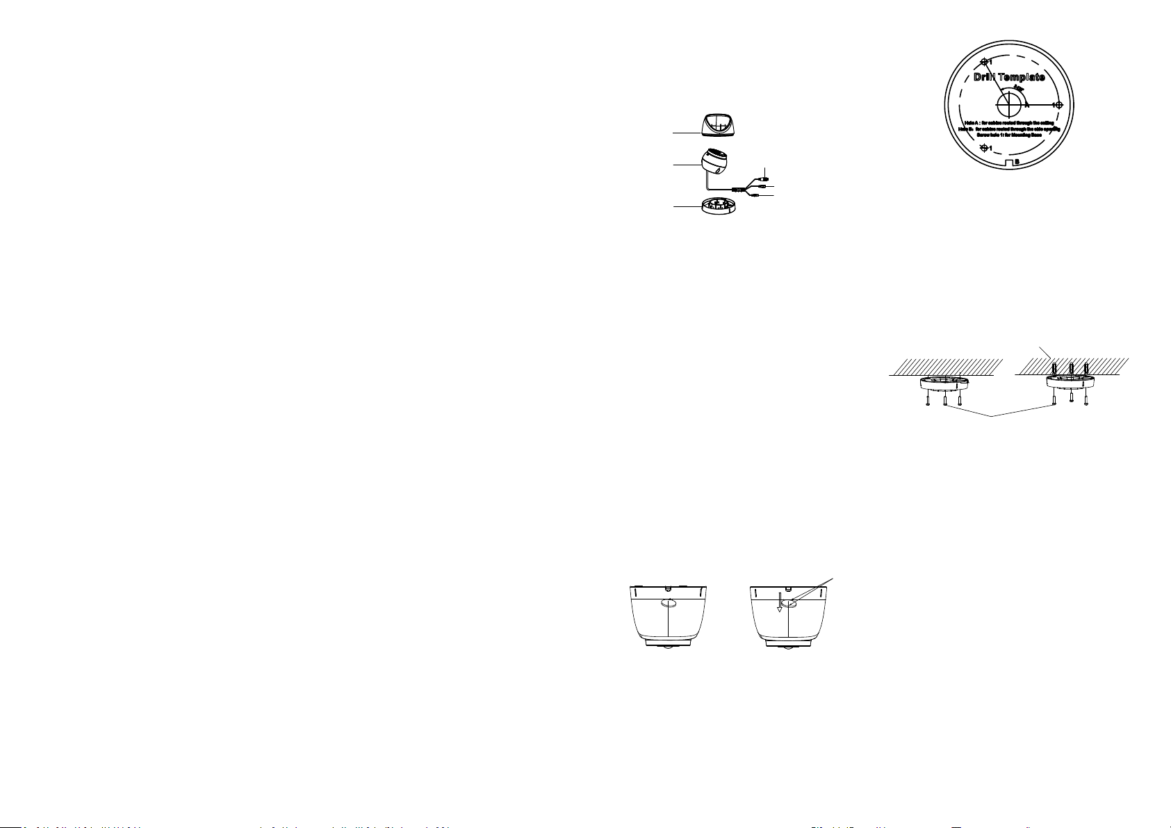
1.2 Overview
1.2.1 Overview of Camera
Enclosure
Main Body
Mounting
Base
Alarm Cable
DC12VIN
Power Cord
Video Cable
Figure 1-1 Overview of the Camera
2 Installation
2.1 Ceiling Mounting/Wall Mounting without
Junction Box
Before you start:
The steps of ceiling mounting and wall
mounting are similar. The following takes the
ceiling mounting as an example to describe the
steps.
Steps:
1. Disassemble the camera.
1.1. Rotate the camera to align the notch to
one of the line showed on the camera.
1.2. Pry the mounting base by using tools, e.g. a
coin.
Coin
Figure 2-1 Disassemble the Camera
2. Paste the drill template (supplied) to the
place where you want to install the camera.
3. Drill the screw holes, and the cable hole
(optional) in the ceiling/wall according to the
drill template.
Figure 2-2 Drill Template
Note:
Drill the cable hole, when adopting the ceiling
outlet to route the cable.
4. Attach the mounting base to the ceiling/wall,
and secure them with supplied screws.
Expansion Bolts
Fixing Screws
Figure 2-3 Attach the Mounting Base to the Ceiling
Note:
The supplied screw package contains self-
tapping screws, and expansion bolts.
For a cement wall/ceiling, expansion bolts
are required to fix the camera. For a
wooden wall/ceiling, self-tapping screws
are required.
5. Route the cables through the cable hole, or
the side opening.
6. Install the camera back to the mounting
base, and tighten the screws to secure it on
the mounting base.
Page 3
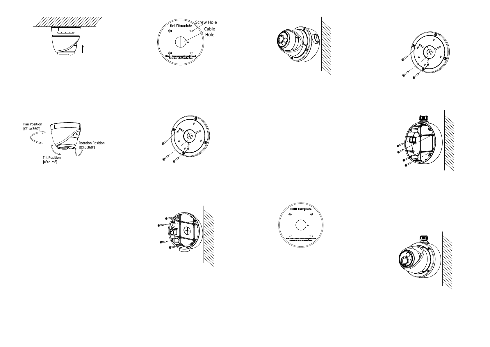
Figure 2-4 Install the Camera back to the
Mounting Base
7. Connect the corresponding cables, such as
power cord, and video cable.
8. Power on the camera to check whether the
image on the monitor is gotten from the
optimum angle. If not, adjust the camera
according to the figure below to get an
optimum angle.
Figure 2-6 The Drill Template
3. Disassemble the inclined ceiling mount with
the screw driver.
4. Install the turret camera’s mounting base on
the inclined ceiling mount’s cover with the
three PM4 screws.
Figure 2-9 Install the Camera to the Inclined
Ceiling Mount
2.3 Ceiling/Wall Mounting with Junction Box
Before you start:
You need to purchase a junction box
separately.
4. Install the mounting base on the junction
box’s cover by supplied screws.
Figure 2-11 Install the Turret Camera’s
Mounting Base
5. Secure the junction box’s body to the
ceiling/wall with the supplied screws.
Figure 2-5 3-axis Adjustment
9.1. Adjust the pan position [0° to 360°].
9.2. Adjust the tilt position [0° to 75°].
9.3. Adjust the rotation position [0° to 360°].
2.2 Mounting with Inclined Ceiling Mount
Before you start:
You need to purchase an inclined ceiling mount
separately.
Steps:
1. Paste the drill template (supplied) to the
place where you want to install the camera.
2. Drill screw holes, and the cable hole on the
ceiling/wall according to the supplied drill
template.
Figure 2-7 Install Turret Camera’s Mounting
Base
5. Install the inclined ceiling mount’s body to
the ceiling/wall with the four PA4 × 25
screws.
Figure 2-8 Install the Inclined Ceiling Mount’s
Body
6. Combine the inclined ceiling mount’s cover
with its body with the supplied screws.
Repeat steps 5 to 9 of Chapter 2.1 Ceiling
Mounting/Wall Mounting without Junction
Box to complete the installation.
Steps:
1. Paste the drill template on the ceiling/wall.
2. Drill screw holes and the cable hole
(optional) in the ceiling/wall according to
the holes of the drill template.
Figure 2-10 Drill Template of the Junction Box
Note:
Drill the cable hole when adopting the ceiling
outlet to route the cable.
3. Take apart the junction box, and align the
screw holes of the turret camera’s mounting
base with those on the junction box’s cover.
Figure 2-12 Secure the Junction Box’ Camera
Body to Ceiling/Wall
6. Combine the junction box’s cover with its
body.
7. Repeat steps 5 to 9 of Chapter 2.1 Ceiling
Mounting/Wall Mounting without Junction
Box to install the camera to the junction
box.
Figure 2-13 Install the Camera to the Junction
Box
Page 4
2.4 Wall Mounting
TVI DVR
Before you start:
You need to purchase a wall mount separately.
Steps:
1. Drill four screw holes in the wall according
to the holes of the mount.
2. Install the mount to the wall by aligning the
four screw holes of the bracket with the
expansion screws on the wall.
3. Secure the mount with four hex nuts and
washers.
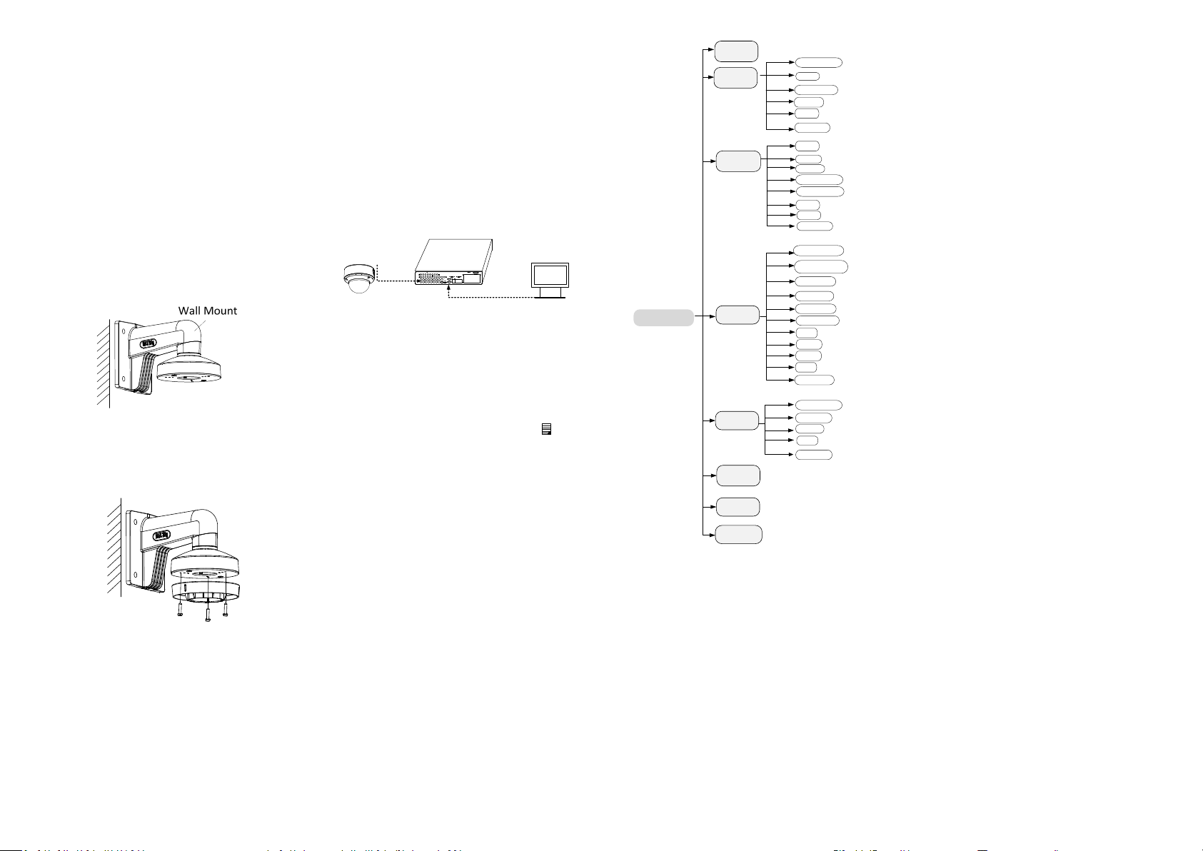
Figure 2-14 Install the Bracket
4. Install the mounting base of the turret
camera to the wall mount, and secure them
with the supplied screws.
Figure 2-15 Install the Mounting Base to the
Bracket
5. Route the cables through the mount.
6. Repeat steps 6 to 9 of Chapter 2.1 Ceiling
Mounting/Wall Mounting without Junction
Box to complete the installation.
3 Menu Description
Follow the steps below to call the menu.
Note:
The actual display may vary with your camera
model.
Steps:
1. Connect the camera with the TVI DVR, and
the monitor, as shown in figure 3-1.
Camera
Monitor
Figure 3-1 Connection
2. Power on the camera, TVI DVR, and the
monitor to view the image on the monitor.
3. Click PTZ Control to enter the PTZ Control
interface.
4. Call the camera menu by clicking the
button, or call the preset No. 95.
VIDEO FORMAT
EXPOSURE
DAY/NIGHT
MAIN MENU
VIDEO SETTINGS
FUNCTIONS
FACTORY
DEFAULT
EXIT
EXPOSURE MODE
AGC
SLOW SHUTTER
BACK
EXIT
SAVE & EXIT
MODE
IR LIGHT
Smart IR
D->N THRESHOLD
N->D THRESHOLD
BACK
EXIT
SAVE & EXIT
IMAGE MODE
WHITE BALANCE
BRIGHTNESS
CONTRAST
SHARPNESS
SATURATION
3 DNR
MIRROR
BACK
EXIT
SAVE & EXIT
MOTION DET
PRIVACY
BACK
EXIT
SAVE & EXIT
3.2 EXPOSURE
EXPOSURE MODE
You can set the EXPOSURE MODE to GLOBAL,
BLC, HLC, or WDR.
GLOBAL
GLOBAL refers to the normal exposure mode
which adjusts lighting distribution, variations,
and non-standard processing.
BLC (Backlight Compensation)
BLC (Backlight Compensation) compensates
light to the object in the front to make it clear,
but this may cause over-exposure of the
background where the light is strong.
HLC (Highlight Compensation)
HLC stands for highlight compensation. The
camera detects the strong spots (the overexposure portion of image), then reduces the
brightness of the strong spots to improve the
overall images.
WDR (Wide Dynamic Range)
The wide dynamic range (WDR) function helps
the camera provide clear images even under
back light circumstances. When there are both
very bright and very dark areas simultaneously
in the field of view, WDR balances the
brightness level of the whole image and
SAVE & EXIT
Figure 3-2 Main Menu Overview
5. Click the direction arrow to control the
camera.
(1) Click the up/down direction button to select
the item.
(2) Click Iris + to confirm the selection.
(3) Click the left/right direction button to adjust
the value of the selected item.
3.1 FORMAT
You can set the video format to 2MP@25fps or
provides clear images with details.
AGC (Auto Gain Control)
It optimizes the clarity of the image in poor
light conditions. The AGC level can be set to
HIGH, MEDIUM or LOW.
Note:
The noise will be amplified when the AGC is on.
SLOW SHUTTER
SLOW SHUTTER increases the exposure time on
a single frame, which makes a camera more
sensitive to the light so it can produce images
even in low lux conditions.
2MP@30fps.
Page 5
You can set the SLOW SHUTTER function as
OFF, x2, x4, x6, x8, x10, x12, x14, or x16
according to the different light conditions.
Note:
This function is not available, when adopting
power over coaxial to supply power.
3.3 DAY/NIGHT
COLOR, B&W (Black White), and AUTO are
selectable for DAY and NIGHT switches.
COLOR
The image is colorful in day mode all the time.
B&W
The image is black and white all the time. It is
recommended turn the IR LIGHT on in poor
light conditions.
IR LIGHT
You can turn on/off the IR LIGHT to meet the
requirements of different circumstances.
SMART IR
The Smart IR function is used to adjust the light
to its most suitable intensity, and prevent the
image from over exposure. The SMART IR value
can be adjusted from 0 to 3. The greater the
value is, the more obvious effects are.
AUTO
You can turn on/off the IR LIGHT, and set the
value of SMART IR in this menu.
DAY/NIGHT
MODE
IR LIGHT
SMART IR
D->N THRESHOLD
N->D THRESHOLD
BACK
EXIT
SAVE&EXIT
AUTO
ON
2
2
7
Figure 3-3 DAY/NIGHT
IR LIGHT
You can turn on/off the infrared to meet the
requirements of different circumstances.
SMART IR
The Smart IR function is used to adjust the light
to its most suitable intensity, and prevent the
image from over exposure. You can choose
MODE 1 or MODE 2. MODE 1 could reach the
most ideal effects of the low illumination, but it
might cause a delay by contrast with the actual
scenario. MODE 2 represents the normal mode.
The SMART IR value can be adjusted from 0 to
3. The greater the value is, the more obvious
effects are.
D►N THRESHOLD (Day to Night Threshold)
Day to Night Threshold is used to control the
sensitivity of switching the day mode to the
night mode. You can set the value from 1 to 9.
The larger the value is, the more sensitive the
camera is.
N►D THRESHOLD (Night to Day Threshold)
Night to Day Threshold is used to control the
sensitivity of switching the night mode to the
day mode. You can set the value from 1 to 9.
The larger the value is, the more sensitive the
camera is.
3.4 VIDEO SETTINGS
Move the cursor to VIDEO SETTINGS and click
Iris+ to enter the submenu. IMAGE MODE,
WHITE BALANCE, BRIGHTNESS, CONTRAST,
SHARPNESS, SATURATION, 3 DNR, and
MIRROR are adjustable.
VIDEO SETTINGS
IMAGE MODE STD
WHITE BALANCE
BRIGHTNESS
CONTRAST
SHARPNESS
SATURATION
3DNR
MIRROR
BACK
EXIT
SAVE & EXIT
5
5
5
5
5
OFF
Figure 3-4 VIDEO SETTINGS
IMAGE MODE
IMAGE MODE is used to adjust the image
saturation, and you can set it as STD
(Standard), or HIGH-SAT (High Saturation).
WHITE BALANCE
White balance, the white rendition function of
the camera, is to adjust the color temperature
according to the environment. It can remove
unrealistic color casts in the image. You can set
WHITE BALANCE mode as AUTO, or MANUAL.
AUTO
Under AUTO mode, white balance is being
adjusted automatically according to the color
temperature of the scene illumination.
MANUAL
You can set the R-GAIN/B-GAIN value to adjust
the shades of the red/blue color of the image.
WHITE BALANCE
MODE
R-GAIN
B-GAIN
BACK
EXIT
SAVE&EXIT
MANUAL
5
5
Figure 3-5 MANUAL WHITE BALANCE MODE
BRIGHTNESS
Brightness refers to the brightness of the
image. You can set the brightness value from 1
to 9 to darken or brighten the image. The
greater the value is, the brighter the image is.
CONTRAST
This feature enhances the difference in color
and light between parts of an image. You can
set the CONTRAST value from 1 to 9.
SHARPNESS
Sharpness determines the amount of detail an
imaging system can reproduce. You can set the
SHARPNESS value from 1 to 9.
SATURATION
Adjust this feature to change the saturation of
the color. The value ranges from 1 to 9.
3 DNR (3D DNR)
3 DNR refers to 3D digital noise reduction.
Comparing with the general 2D digital noise
reduction, the 3D digital noise reduction
function processes the noise between two
frames besides processing the noise in one
frame. The noise will be much less and the
video will be clearer.
MIRROR
OFF, H, V, and HV are selectable for mirror.
OFF: The mirror function is disabled.
H: The image flips 180° horizontally.
V: The image flips 180° vertically.
HV: The image flips 180° both horizontally and
vertically.
3.5 FUNCTIONS
3.5.1. WHITE LIGHT
The embedded white light source can be
worked as the visible alarm, or the lighting.
In the WHITE LIGHT mode, you can set the
mode as ALARM, LIGHTING, or OFF.
Note:
The LIGHTING option might depend on the
specific model that you have.
When you select the WHITE LIGHT as ALARM,
you can set the parameters in the TRIGGER
MODE, the EXT ALARM OUT, and the ALARM
MODE to meet your needs.
TRIGGER MODE
DVR
Select the TRIGGER MODE as DVR. In this way,
the alarm signal is sent from the DVR, and the
camera works as the alarm detector in the
Page 6
process. Follow the steps below to achieve the
visual and audible alarm:
Note:
You need to purchase and connect a bell in
advance.
1). Select the ALARM MODE as DVR.
2). Select the EXT ALARM OUT as ON.
3). Save and exit.
FUNCTIONS
WHITE LIGHT
TRIGGER MODE
EXT ALARM OUT
ALARM MODE
TIME SETTINGS
PIR LEVEL
PIR DET MODE
MOTION DET
PRIVACY
BACK
EXIT
SAVE & EXIT
ALARM
DVR
OFF
SOLID
15S
3
INDOOR
Figure 3-6 TRIGGER MODE
CAMERA
Select the TRIGGER MODE as CAMERA, the
embedded PIR module sends the alarm signal
to trigger visual alarm, when PIR module
detects the alarm source.
ALARM MODE
In the ALARM mode, you can select the ALARM
MODE as SOLID, or FLASHING.
WHITE LIGHT
TRIGGER MODE
ALARM MODE
TIME SETTING
PIR LEVEL
PIR DET MODE
MOTION DET
PRIVACY
BACK
EXIT
SAVE & EXIT
FUNCTIONS
ALARM
CAMERA
SOLID
15 S
3
INDOOR
Figure 3-7 ALARM MODE
SOLID
Select the ALARM MODE as SOLID. In this way,
the white light source turns on, when the PIR
module receives the alarm signal.
TIME SETTING means you can set the duration
of the light that keeps solid when the camera
receives one alarm signal.
Note:
The solid mode will be stayed for another set
time when second alarm signal is received, and
the rest can be done in the same way.
FLASHING
Select the ALARM MODE as FLASHING. In this
way, the white light source flashes when the
PIR module received the alarm signal.
LIGHTING
Select the LIGHTING mode, the embedded
white light source turns on in poor light
conditions automatically.
You can set the LIGHTING MODE as SOLID or
FLASHING.
SOLID
The white light source turns on in the poor light
conditions.
FUNCTIONS
WHITE LIGHT
LIGHTING MODE
PIR LEVEL
PIR DET MODE
MOTION DET
PRIVACY
BACK
EXIT
SAVE & EXIT
LIGHTING
SOLID
3
INDOOR
Figure 3-8 SOLID
FLASHING
When you select the LIGHTING MODE as
FLASHING, you can set the TRIGGER MODE as
CAMERA, or DVR.
The white light source flashes in the poor light
conditions when receiving the alarm signal.
FUNCTIONS
WHITE LIGHT
LIGHTING MODE
TRIGGER MODE
PIR LEVEL
PIR DET MODE
MOTION DET
PRIVACY
BACK
EXIT
SAVE & EXIT
LIGHTING
FLASHING
CAMERA
3
INDOOR
Figure 3-9 FLASHING
OFF
Select OFF to give up this function.
3.5.2. PIR LEVEL
Adjust the sensitivity of the PIR module, and
the higher the value is, the more sensitive the
PIR module is.
3.5.3. PIR DET MODE
OUTDOOR and INDOOR are selectable for PIR
DET MODE switch.
3.5.4. MOTION DET
You can turn on/off the MOTION DET to meet
different circumstances.
3.5.5. PRIVACY
You can turn on/off the PRIVACY to meet
different circumstances.
3.6 FACTORY DEFAULT
Reset all the settings to factory default.
3.7 EXIT
Move the cursor to EXIT and click Iris+ to exit
the menu.
3.8 SAVE & EXIT
Move the cursor to SAVE & EXIT and click Iris+
to save the settings, and exit the menu.
WWW.GRUNDIG-SECURITY.COM
UG-GD-CT-AC2116E-2019-02-03-V3-EN ©ABETECHS GMBH, DÜSSELDORF, GERMANY
 Loading...