

Page 1
COLOR TELEVISION
T 55-930 FT/GB
Page 2
ķ
2
Connection Possibilities
❒
Contents
Connection Possibilities . . . . . . . . . . . . . . . . . . . . . . . . . . . . . . . . . . . . . 2
Set-up, Safety and Preparation . . . . . . . . . . . . . . . . . . . . . . . . . . . . . . . . 3
Connecting and Operating the set . . . . . . . . . . . . . . . . . . . . . . . . . . . . . . 4
Settings . . . . . . . . . . . . . . . . . . . . . . . . . . . . . . . . . . . . . . . . . . . . . . . . 5-8
Operation with the Remote Control . . . . . . . . . . . . . . . . . . . . . . . . . . . 9-10
Teletext Mode (Fasttext) . . . . . . . . . . . . . . . . . . . . . . . . . . . . . . . . . . 11-12
Connection Possibilties . . . . . . . . . . . . . . . . . . . . . . . . . . . . . . . . . . 13-15
Technical Data . . . . . . . . . . . . . . . . . . . . . . . . . . . . . . . . . . . . . . . . . . . . 16
Ń
!
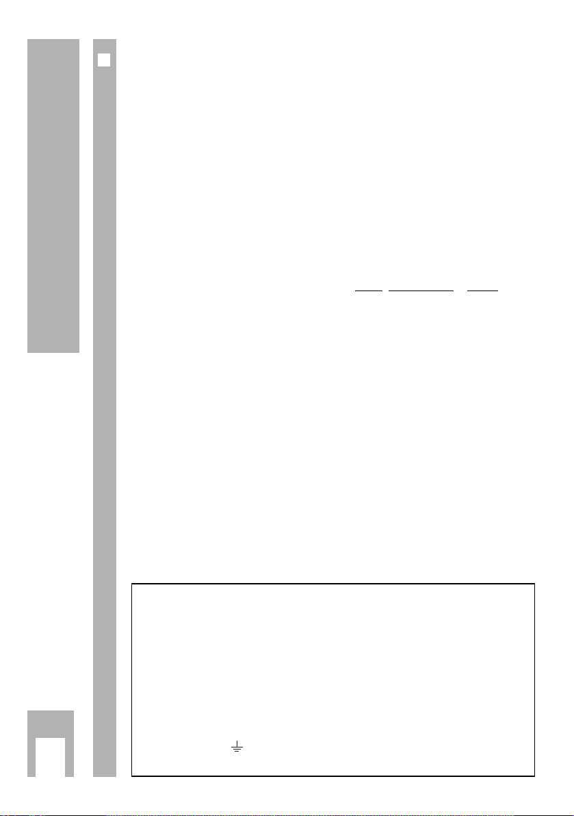
Warning
In case this appliance is supplied with a Safet
y Standar
d Approved mains
lead fitted with a non-rewireable 13 Amp mains plug which, if unsuitable for
your socket, should be cut off and an appropriate plug fitted by a qualified
electrician. The fuse and fuse holder must be removed from the plug as
accidental insertion of the redundant plug into a 13 Amp socket is likely to
cause an electrical hazard.
Note:The severed plug must be destroyed to avoid a possible shock hazard
should it be inserted into a 13 Amp socket elsewhere.
If it is necessary to change the fuse in the non-rewireable plug, the correct
type and rating (5 Amp ASTA or BSI approved BS 1362) must be used and
the fuse cover must be refitted. If the fuse cover is lost or damaged the lead
and plug must not be used until a replacement is obtained. Replacement
fuse covers should be obtained from your dealer.
If a non-rewireable plug or a rewireable 13 Amp (BS 1363) plug is used, it
must be fitted with a 5 Amp ASTA or BSI approved BS 1362 fuse. If any
other type of plug is used it must be protected by a 5 Amp fuse either in the
plug or at the distribution board.
Important:
The wires in the mains lead are coloured in accordance with the following code:
BLUE – NEUTRAL
BROWN – LIVE
As the colours of the wires in the mains lead of your appliance may not correspond with
the coloured marking identifying the terminals in your plug, proceed as follows:
Connect the BLUE coloured wire to plug terminal marked with the letter "N" or coloured
black.
Connect the BROWN coloured wire to the plug terminal marked with a letter "L" or colou-
red red.
In no circumstance must any of the wires be connected to the terminal marked with a let-
ter "E", earth symbol , coloured green or green and yellow.
Replacement mains lead can be obtained from your dealer.
Page 3

Set-up, Safety and Preparation
ķ
3
❒
Set-up and Safety
Ń
!
The minimum spacings – 10 cm on each side and 20 cm at the top – must
be observed for operation in a wall unit.
Do not cover the ventilation openings on the rear panel.
Heat accumulation poses a risk and is detrimental to the service life of the
equipment.
Do not place the set near to heating appliances.
Ń
!
The mains cable must not be clamped or damaged. The set may only operated supplied power cable set.
Even if the set is switched off, it could be damaged by a lightning strike hitting the mains and/or the aerial lead.
Therefore, always disconnect the mains plug and aerial plug when storms
are apparent.
Protect the set from moisture and dripping or splashing water.
Do not insert any objects into the ventilation openings.
Caution high voltage!
❒
Inserting the Batteries in the Remote Control
Insert the batteries supplied observing the polarity (marked on base of
battery compartment).
»Batter.« will appear on the set screen when the battery is flat.
Ensure that used batteries are removed and disposed of in an environmentally friendly way.
There is no liability for damage occuring through dead batteries.
Ǻ
Page 4
Connection and Operation on the Set
ķ
4
❒
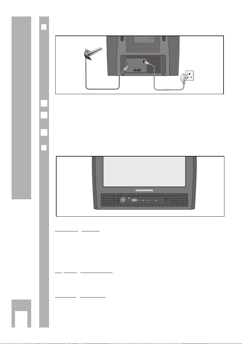
Connection
Connect the aerial cable plug to the aerial socket É on the set.
Connect the mains cable plug to the set mains socket and to the wall
socket.
Connection of external equipment is described on pages 13 and 14.
❒
Operation on the Set
Switchin
g on/off
Press the übutton.
– If the display then illuminates, the set is in standby mode.
Switch the set on completely with the P ›+button.
Adjusting the volume
Adjust the volume with the ›–z ›+buttons.
Selecting channels
Select the channels with the ›
–
P ›
+
buttons.
y
P
Ǻ
2
1
EURO-AV
Page 5
Settings
ķ
5
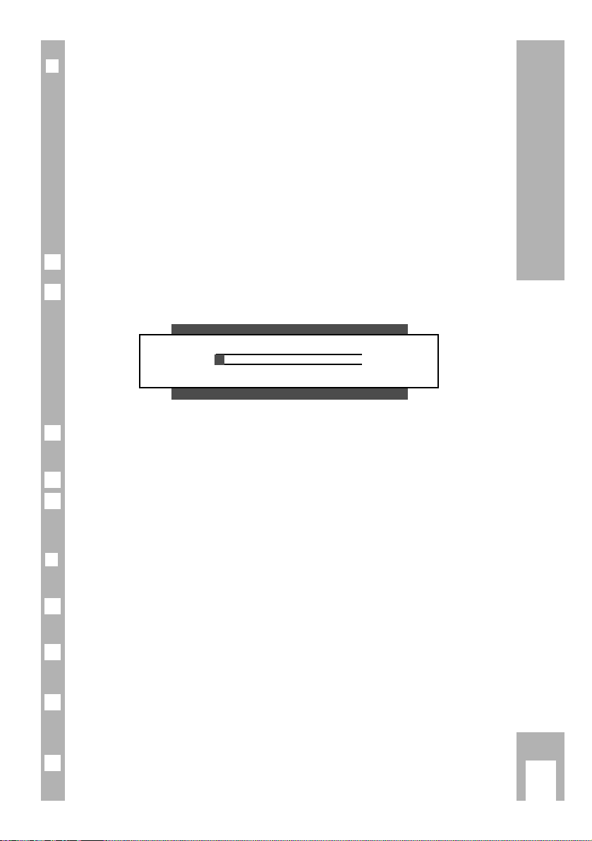
❒❒
Assigning Channel Positions with the ATS Automatic
Channel Search and Memory System
There are 69 channel positions available which can be assigned television
channels from the aerial or from the cable connection as desired.
The set is equipped with an automatic channel search system, ATS.
You start the search and can then sort the television channels into an order
of your choice.
You can also delete television channels which were found several times or
which have poor reception from the channel list.
»ATS« is displayed when the set is switched on.
If »ATS« is not displayed, press the
›
AUX
button for approx. 4 seconds until
the display appears.
Start the search with the G button.
– The search procedure can take over a minute.
The search can be aborted with the h button.
Once the set has stored all television channels it will switch to channel
position 1.
❒
Deleting Television Channels
You can delete television channels with poor reception.
Press the h and then the G button.
– The »Channel Display« will appear.
Select the channel position whose television channel should be deleted with
the p
or P button.
Delete the television channel by pressing the ›
TXT
and then the G button.
– The subsequent television channels will move by one channel position
to the front.
End the setting with the h button.
4
3
2
1
Ǻ
Ǻ
2
Ǻ
1
ATS
OK
i
Page 6

Settings
ķ
6
❒
Sorting Program Positions
Select the channel position which is to be moved with the p or P button.
Press the h and then the G button.
– The »Channel Display« will appear.
Enter the new channel position with the digit buttons 0 and 9 using two
digits and confirm with the G button.
End the setting with the h button.
❒
Limiting the Channel Position Selection
The ATS search stores all television channels found and automatically
“blocks” the first non-assigned channel position. This means only the found
television channels can be selected when you switch through the channel
positions stey by step with the p or P buttons.
You can also enter this limit manually. Channel position 6 onwards has been
“blocked” in the example.
Press the h and then the G button.
– The »Channel Display« will appear.
Select channel position 6 with the p or P button.
Press the E button once (position
„
) and enter the »Channel Postion
Limit« (----) with the p or P button.
Store the setting with the G button and end with the h button.
– Now only the first 5 channel positions (and AV) can be switched through
in quick sequence with the p or P button.
– All channel positions – including the “blocked” ones – can still be selected
with the digit buttons 0 … 9.
4
3
2
1
4
3
2
1
P+
Ń
6 ---- ➞
■
0 DEC1
ľľ
--- ■-------- ■-------------- ■-------- ■-------------------- ■------
ıı
0-9 TXT OK i
➡
„
Page 7

Settings
ķ
7
❒
Manually Assigning Channel Positions
This setting is only required if, for example, a new television channel is
added to the cable selection and you want to keep your special channel
position order (e.g. BBC1 = 1, BBC2 = 2 … etc.).
Example:
You want to set a new television channel in the »UHF« frequency band (special channel S 40-S 41, channel C21-C 69) to channel position »14«.
Press the h and then the G button.
– The »Channel Display« will appear.
– The picture explains the different setting possibilities. Select the position
either with the F or E button, then enter with the p
or P button.
!
Channel position
§
Channel search
$
standard (television norm)
"
Frequency band
%
Decoder on/off (DEC1/DEC 0)
UHF (S 40-S 41, C21-C 69) or DEC1 – Only if an encoded
---- (channel position limitation) television channel is received and a
corresponding decoder is connected
.
The positions !, "and §of the picture are referred to in the example.
Press the p or P button repeatedly until the channel position »14« is displayed under position.
Select the band UHF, (or ---- with the p/P button – see page 6). position
"
with the E.
3
2
Ǻ
1
P+
Ń
14 UHF ➞
■
0 DEC0
ľľ
--- ■-------- ■-------------- ■-------- ■-------------------- ■------
ıı
0-9 TXT OK i
Page 8

Settings
ķ
8
Select position §with the Ebutton and then press the p or P button.
– The »Channel Search« display will appear.
Start channel search by holdin
g down the F or E button.
– The channel search will stop at each receivable television channel.
– Start the channel search repeatedly until the desired television channel
appears on the screen.
The picture and sound can be fine tuned b
y pressing the F or E button
repeatedly and briefly.
This fine tuning procedure is only possible for channel positions 1 to 20.
End the channel search with the h button.
– The »Channel Display« will appear.
The television norm (standard) – position
$
– cannot be changed.
Store the setting for this channel position with the G button.
End the setting with the h button.
8
7
Ǻ
6
Ǻ
5
4
P14 S40 – S41, C21–C69
ľľ ıı
ņ –+ŀ Ǻ
Page 9

Operation with the Remote Control
ķ
9
Switch on the set from standby mode
(AV 0…9, P).
Select channel positions (including
AV) directly (AV 0…9).
❒❒
Functions for Daily Television Operation
Switch on the set with the übutton.
Select channel position step by step
(
p
,
P
).
Sound on/off (mute) (›ĭ).
Switch the set to standby mode
(A).
Adjust volume (
FE
).
Fade channel position number
in/out (h).
The station name is also displayed
with some television channels.
Time on/off (9).
Adjust brightness (›
–
v
›+).
Adjust colour contrast (›
–
i ›
+
)
.
Each changed value (volume,
brightness, colour contrast) will be
stored after approx. 8 seconds.
Reset to the factory setting by pressing the ›
AUX
button and then the G
button.
21
3
654
987
0
P
OK
P
TXTAUX
E
Ȅ
F
VIDEO
VIDEO
SAT/TV
TP 715
Page 10

Operation with the Remote Control
ķ
10
❒
Further Functions for Television Operation
Ad
justing black/white contrast:
Press the -button, then adjust with the ›
–
v
›+buttons.
Entering the switch-off time for the “Sleep Timer”:
Press the -and then the
¢
TXT
button.
Enter the switch-off time with the digit buttons 0 … 9 (01 to 99 minutes).
End the setting with the h button.
The functions of the p
, P, F, E and G buttons for settings are descri-
bed in the chapters on pages 5 to 8.
❒
Remote Control of Grundig Video Recorders
Press the
›
VIDEO button and keep depressed.
The following list shows which buttons can be used to operate the functions of the video recorder.
p = Channel position downwards
p = Channel position upwards
● (h button) = start recording
ı (G button) = start playback
II (›ĭbutton) = pause
ĵ
<
(F button) = reverse picture search
>
Ł (E button) = forwards picture search
■ (Taste
AV
0) = stop
❒
Remote Control of Grundig Satellite Receivers
Press the
›
SAT button and keep depressed.
Select the satellite channel with the P or p button.
Switch the satellite receiver to standby with the A button.
Switch the satellite receiver on from standby with the 1…9,
P
buttons.
4
3
2
1
2
1
Ǻ
3
2
1
Page 11

Teletext Mode
ķ
11
❒
Functions for Daily Teletext Operation
Teletext consists of a large number of text pages containing, for example,
news from sport and politics, market prices, weather reports and much
more information.
The teletext offer and also the organisation and structure of the individual
pages differs from broadcaster to broadcaster.
Select teletext page by entering the
three-digit page number with the
digit buttons (AV 0…9).
The page will appear after a short
time.
Flip back one page (8 red
)
;
flip forwards to the next page
(9 green
)
;
flip forwards 10 pages (
i
yellow
)
;
flip forwards 100 pages (o blue).
Fasttext (Flof)
The coloured buttons are for the
topics listed in the dialog lines.
Call up subpage directly (›
–
i
),
then enter the four-digit number for
the subpage with the digit buttons
AV 0…9;
Double character size (i ›+)
;
Page stop (›
–
v
);
Reveal answer (v›+).
Return to contents page 100 (h).
Switch teletext mode on/off (
¢
TXT
).
The contents page 100 or the
teletext page last viewed appears.
21
3
654
987
0
VIDEO
VIDEO
P
OK
P
TXTAUX
E
Ȅ
F
SAT/TV
TP 715
Page 12

Teletext Mode
ķ
12
❒
Further Functions for Teletext Mode
These functions are selected with the “Symbol Line”.
Switch on teletext with the
¢
TXT
button.
Press the -button.
– The symbol line will appear at the bottom of the screen.
Double character size ;
Bridge waiting time
Call up subpage directly
Reveal answer
Page stop
Select function with the
F or E button.
Call up function with the G button.
Switch off the teletext with the
¢
TXT
button.
Selecting and calling up particular teletext pages directly –
“Pa
geCatching”
There are three-digit page numbers which can be selected directly on many
contents pages.
Switch on teletext with the
¢
TXT
button.
Activate the »PageCatching« function with the p or P button.
– »PageCatching OK« will appear at the top of the screen.
A bright rectangle will flash behind the first or last page number of the
contents page.
Select the desired page number with the p or P button and confirm with
the G button.
– The page will appear on the screen after a short time.
Switch off the teletext with the
¢
TXT
button.
4
3
2
1
5
4
3
G KHLI
2
1
Page 13

Connection Possibilities
ķ
13
❒
Video Recorder, Satellite Receiver or Camrecorder
Connection
Connect the »EURO-AV« socket on the television set to the corresponding
socket on the video recorder or satellite receiver with a EURO/AV (Scart)
cable.
Teletext mode is not possible if the satellite receiver is connected via the
Euro-AV socket.
If the satellite receiver also has an HF aerial output, this socket can be used
to enable teletext mode.
Use a conventional adapter cable to connect a camcorder.
Operation
Press the AV 0 button, »AV« will appear.
Start playback on the video recorder or camcorder or switch on the satellite
receiver.
– The recorder playback or the satellite receiver channel will appear on the
screen.
Video playback via the aerial socket
The video recorder can also be connected to the set aerial socket É. The
aerial must then be connected to the aerial socket on the video recorder.
To view the recorder playback a channel position on the set must be tuned
to the video recorder, see setting in the chapter “Manually Assigning Channel Positions”, on page 7.
1
Ǻ
Ǻ
1
EURO-AV
AUDIO
EURO-AV
Page 14

Connection Possibilities
ķ
14
❒
Decoder (Descrambler)
Some stations – whose television channels are transmitted via cable unit or
satellite receiver – encode their transmissions. The picture – and also the
sound with some stations – are then unrecognisable. You can decode such
television channels with a decoder.
Connection
Connect the »EURO-AV« socket on the television set to the corresponding
socket on the decoder with a EURO/AV (Scart) cable.
Setting for Operation with a Decoder
Select the channel position which is assigned the encoded television channel.
Press the h and then the G button.
– The »Channel Display« will appear.
Select the position %»DEC 0« with the For Ebutton.
Select the required »DEC1« setting with the P or p button.
Store the setting with the G button and end with the h button.
5
4
3
2
1
1
EURO-AV
P+
Ń
14 UHF ➞
■
0 DEC0
ľľ
--- ■-------- ■-------------- ■-------- ■-------------------- ■------
ıı
➡
%
Page 15

Connection Possibilities
ķ
15
❒
Headphones
Connection
Insert the headphone plug (3.5 mm ø jack) into the headphone socket y at
the front of the set.
– This switches off the set speaker.
Adjusting the headphone volume
Adjust the headphone volume with the F or E button
.
1
1
y
P
Page 16

Technical Data
ķ
16
❒
Technical Data
The product fulfils the requirements of the following EU guidelines:
73/23/EEC guideline on electrical equipment for use within certain
voltage limits.
89/336/EEC guideline on electromagnetic compatibility.
The set complies with the standards:
EN 60065, EN 55013, EN 55020
Ń
!
The set complies with regulation on protection against x-rays. The x-ray
emission – caused by the tube – is sufficiently shielded and is therefore
completely safe.
Tampering, in particular adjusting the high voltage or installation of a different tube type can lead to the x-ray emission substantially increasing. Sets
which have been modified in such a way no longer correspond with this
approval and must not be operated.
220 – 240V, 50/60 Hz (control range of the power suppply unit 165 – 265V)
Power consumption approx. 55 W; in standby 10 W.
Final sound stage: 2 W music signal power (1 W sinus).
The set may only be operated supplied power cable set. It prevents interfe-
rence from the mains and is an integral component for the set’s approv-al.
For a replacement, consult your nearest customer service centre and order
only the power supply cable set with the following designation
» number 8290.991-386 «.
Page 17

Printed in Germany
21896-941.0101
Grundig UK Limited
Elstree Way, Borehamwood
Hertfordshire WD6 1RX
 Loading...