

Page 1
COLOR TELEVISION
ST 70-755/9 DPL/LOG
Page 2

Contents
ķ
2
GB
F
I
If a specialized dealer has already set up and adjusted the
television, start with page 7 of this manual.
Notes on Safety and Installation
Notes on safety and installation............................... 3
Connecting and Setting Up
Connecting the television ...................................... 4
Inserting the battery into the remote control handset ......4
Switching the unit on/off ....................................... 4
Assigning Channel Positions
The automatic tuning system ATS euro plus.............. 5-6
ATS euro plus - update ..........................................7
Assigning channel positions manually........................7
Fin e tuni n g .......................................................................... 7
Changing the Channel Position Assignment
The TV station table....................................................... 8-10
The Remote Control Handset
The remote control handset.............................................. 1 1
Changing the Sound Setting...
... with the Audio-menu..................................................... 12
Calling up the Audio-menu .............................................. 12
Sound (stereo, two-channel sound, mono)....................... 12
Equalizer ........................................................................... 12
Headphones: connection, volume..................................... 12
Dolby Surround Pro Logic
Loudspeaker systems ......................................... 13
Connecting the loudspeaker boxes .......................... 14
Loudspeakers audio menu ....................................15
Sound effects audio menu.....................................16
Adjusting the Picture
Contrast and sharpness ................................................... 17
Brightness and colour contrast ........................................ 1 7
Switching the picture format ........................................... 1 7
Teletext
Teletext ....................................................................... 18-2 1
Convenient Functions
Security/Timer functions ............................................ 22- 24
Blocking broadcasts unfit for children ............................. 2 3
Blocking all programmes ............................................ 23- 24
Entering a switch-off time (Sleep Timer) ......................... 2 4
Entering a switch-on time (Wake-up Time)...................... 2 4
Special functions ......................................................... 2 5- 26
Connection Capabilities and Operation
For video recorder............................................................. 2 7
For camcorder................................................................... 2 8
For satellite receiver, descrambler .................................. 2 9
For several external units at the same time .................... 3 0
Copying video recordings via the television .................... 3 1
Specification
Specification ..................................................................... 3 2
Page 3
ķ
3
Notes on Safety and Installation
GB
F
I
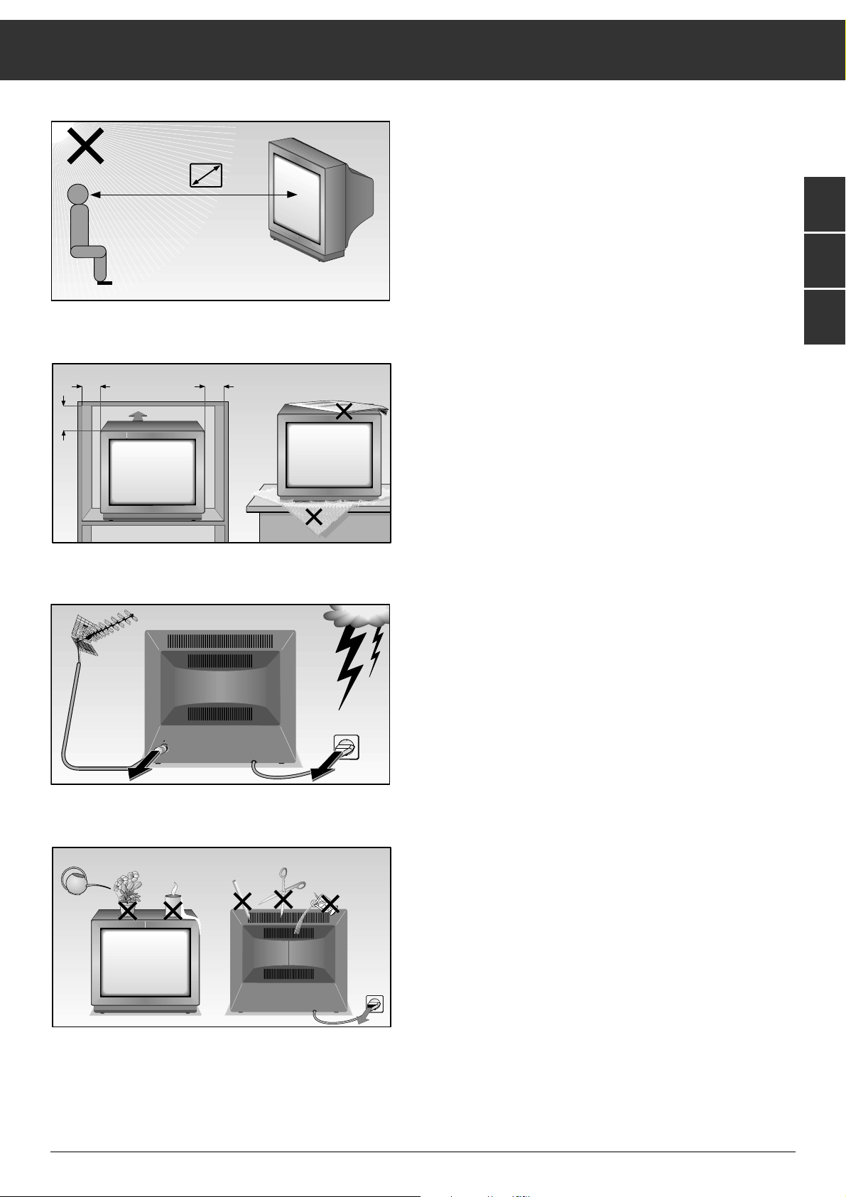
When setting up your television, select a location where as
little light as possible falls on the screen.
The ideal viewing distance is five times the diagonal width of
the screen.
If the television is to be built into a compartment or similarly
enclosed, minimum distances must be maintained.
Do not cover the ventilation openings on the back.
The heat exchange inside the unit generates an air circulation.
which attracts dust particles (carpet and curtain fibres and
home dust). These particles accumulate inside the ventilation
slots obstructing these over the years and causing a build-up
of heat.
Heat build-up can reduce the service life of your television,
and can also be dangerous.
For your own safety, let remove the dust deposits by a
specialist from time to time.
Never set up speakers next to the unit.
When setting up and using this unit, please make sure that
the mains connection lead is free and not jammed in order to
avoid damage.
Never place the television near heat sources.
Even if your television is switched off, it can still be damaged
by lightning striking the mains and/or aerial cables.
For this reason, you should always disconnect your television
from the mains and the aerial system during thunderstorms.
Never expose the unit to moisture.
Do not insert foreign objects into the ventilation openings on
the back.
Caution! High voltage!
5 x
20
cm
10
cm
20 cm
10
cm
Krieg am Golf
! SERVICE !
Page 4
ķ
4
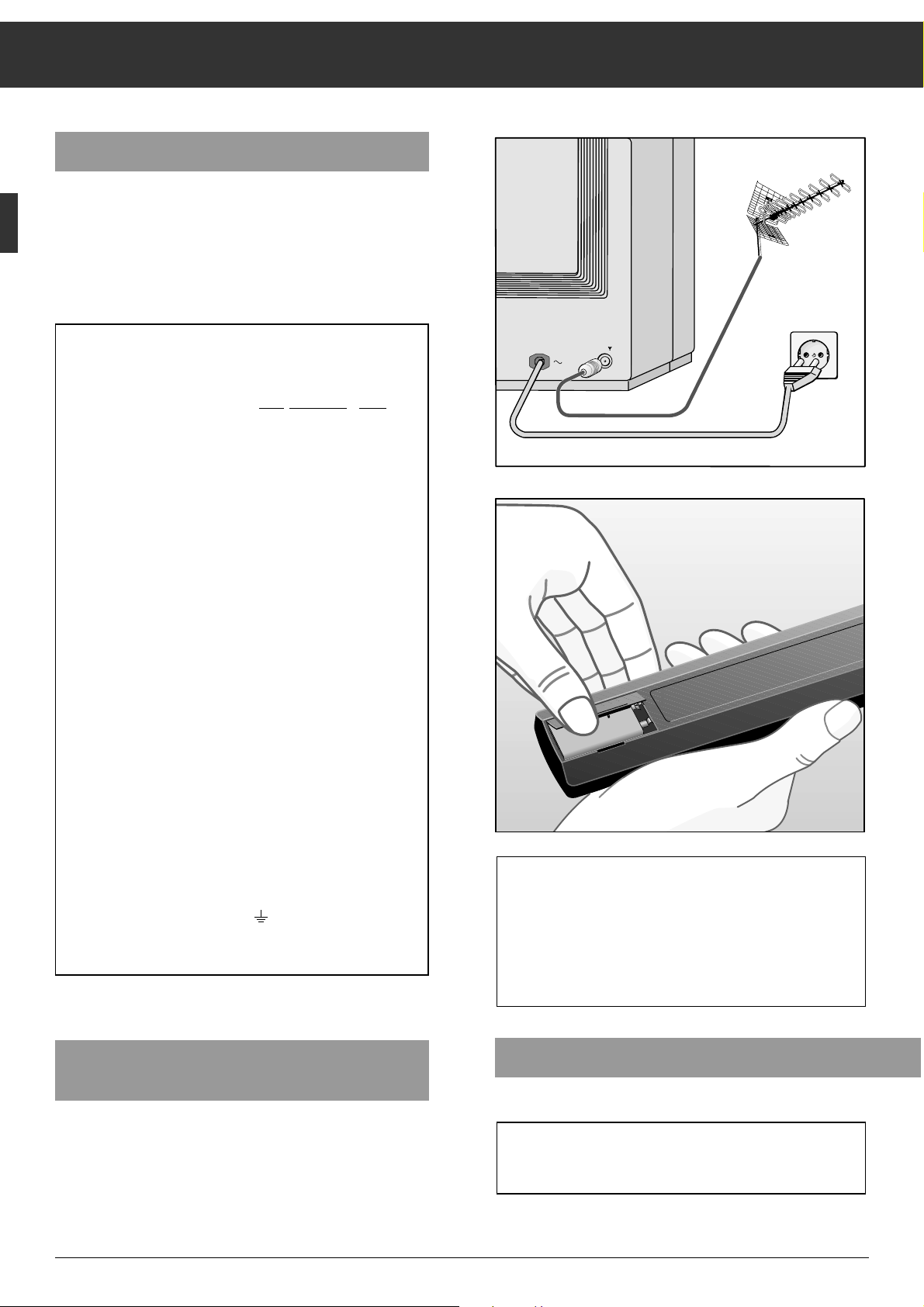
Connecting the Television
Connecting the unit to the aerial
Plug the aerial cable into the aerial socket É on the unit.
Connecting the unit to the mains
Plug the mains cable into the wall socket.
Connecting and Setting Up
Inserting the Battery into the Remote
Control Handset
Remove the battery compartment cover by pressing on the
catch and then removing the cover.
Insert the battery supplied. Make sure it is inserted correctly
(note the markings in the battery compartment).
Additional Information for Units sold in Great Britain
Units sold in GB are suitable for operation from a 240 V AC, 50 Hz mains
supply.
In case this appliance is supplied with a Safet
y Standard Approved mains
lead fitted with a non-rewireable 13 Amp mains plug which, if unsuitable
for your socket, should be cut off and an appropriate plug fitted by a
qualified electrician. The fuse and fuse holder must be removed from the
plug as accidental insertion of the redundant plug into a 13 Amp socket
is likely to cause an electrical hazard.
Note: The severed plug must be destroyed to avoid a possible shock
hazard should it be inserted into a 13 Amp socket elsewhere.
If it is necessary to change the fuse in the non-rewireable plug, the correct type and rating (5 Amp ASTA or BSI approved BS 1362) must be
used and the fuse cover must be refitted. If the fuse cover is lost or
damaged the lead and plug must not be used until a replacement is
obtained. Replacement fuse covers should be obtained from your dealer.
If a non-rewireable plug or a rewireable 13 Amp (BS 1363) plug is used,
it must be fitted with a 5 Amp ASTA or BSI approved BS 1362 fuse. If any
othe type of plug is used it must be protected by a 5 Amp fuse either in
the plug or at the distribution board.
Important:
The wires in the mains lead are coloured in accordance with the following code:
BLUE – NEUTRAL
BROWN – LIVE
As the colours of the wires in the mains lead of your appliance may not
correspond with the coloured marking identifying the terminals in your
plug, proceed as follows:
Connect the BLUE coloured wire to plug terminal marked with the letter
"N" or coloured black.
Connect the BROWN coloured wire to the plug terminal marked with a
letter "L" or coloured red.
In no circumstance must any of the wires be connected to the terminal
marked with a letter "E", earth symbol , coloured green or green and
yellow.
Replacement mains lead can be obtained from your dealer.
Switching the Unit On and Off
Press the
¢
IO
button on the television.
If you do not use the televison for extended periods of time
(e.g., at night), press this button to turn the televison off.
This helps you to save energy.
When the battery is dead, the following display appears on
the screen: "Battery Telepilot".
Dead batteries must be removed immediately.
We assume no responsibility for damage resulting from
battery leakage.
Dead batteries should be disposed of properly (environmental protection).
-
9V
+
Page 5
ķ
5
Assigning Channel Positions
ĻĻĻ
Press the following buttons on the
remote control You will see this on the TV screen Explanations
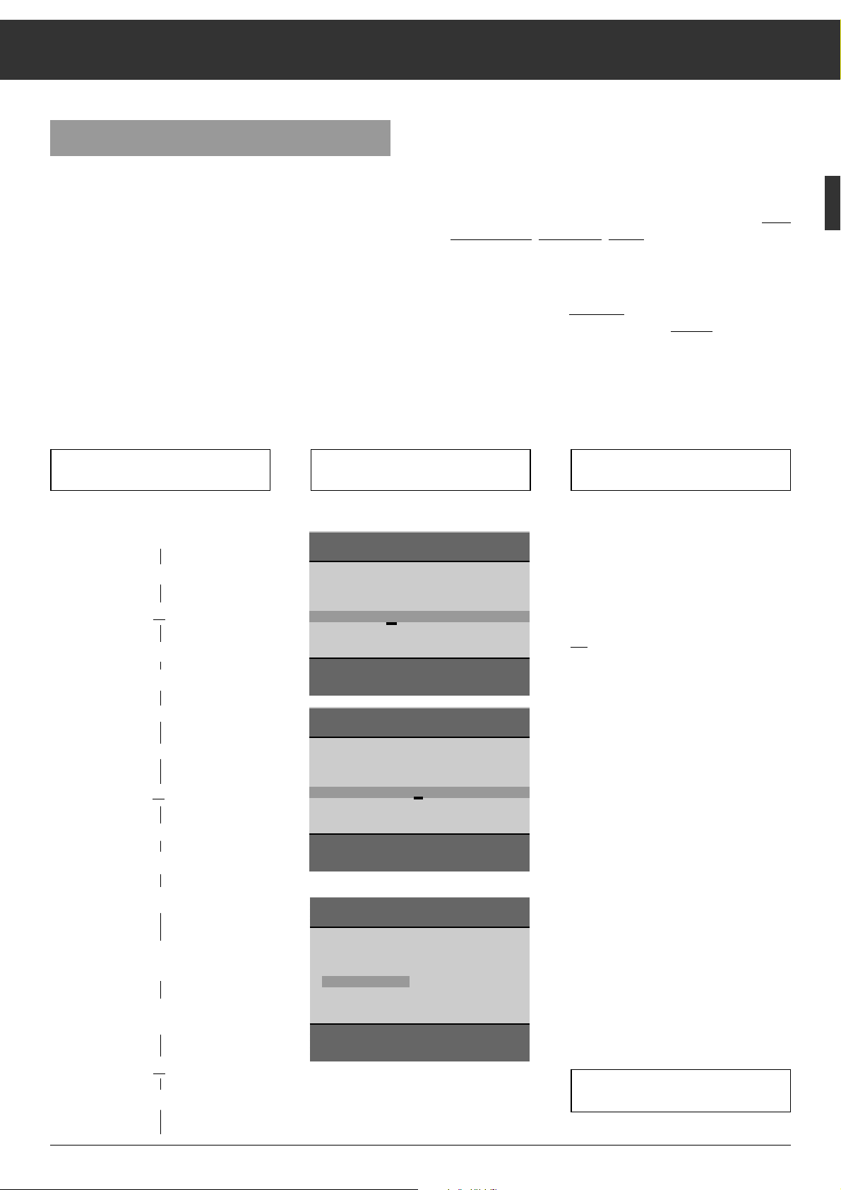
The Automatic Tuning System "ATS euro plus"
After switching on the television set, the "ATS euro plus" page
appears.
If this page does not appear, press and hold down the mbutton until the "ATS euro plus" page appears on the screen.
The dialogue lines at the bottom of the screen are used as
user guide.
The signs ɦ, ɼ,
ʺʺ, ɶɶ
are symbols for the following buttons
on the remote control handset:
ʺʺ, ɶɶ
= programme selection buttons | and ]
ɦ, ɼ = volume x and c
OK = O button
In the following text, the remote control buttons instead of
the symbols will be shown.
Your television is equipped with "ATS euro plus" (Auto Tuning
System). This new system offers you the advantage of automatic channel position assignment.
This search and memory system scans the entire reception
range, stores the channels found, and enters them with their
respective station name (abbreviation) into a TV station table.
You can change the automatic
channel position assignment
as you wish. For example, for channels without identification,
you can choose a name (station name) in a list of abbreviations displayed on the screen and assign it the channel.
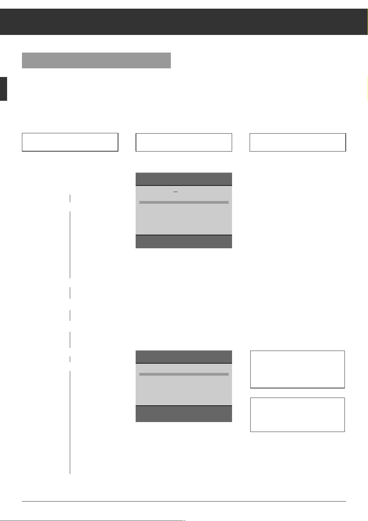
1. Menu guide language
a) Select a language
xor c
b) Confirm
O
2. Country (location)
a) Select a country
xor c
b) Confirm
O
You can choose between several languages for the on-screen dialogue with
your television. After you select a language, all menu guide messages and
information will appear in the language
you selected.
GB
is the factory default setting.
ŁŁ
3. Particularity in France
a) Setting for aerial or cable system
with standard channel spacing
b) Setting for aerial or cable system
with different channel spacing
xor c
O
If you select "F" as country, this menu
wil be displayed.
It allows you to select between
a) "Channel spacing" and
b) "Frequency (MHz)"
for the ATS function.
The "ATS euro plus channel search" is
started.
The television searches for all available
channels, sorts, and stores them.
This procedure can take one minute or
more, depending on the number of
channels that can be received.
When the search procedure is completed, the TV picture received on the first
channel position will be shown.
If you can receive channels in the
SECAM L NICAM colour standard,
observe the information given on
page 12.
If you are in doubt, consult your specialized dealer.
GRUNDIG ATS euro plus
Language
D DK/N E F GB I NL P S SF
Select < >
Confirm OK
Terminate
Ǻ
GRUNDIG ATS euro plus
Country
A B CH D DK E F GB I N
NL P S SF Others
Select < >
ɶ
ʺ
Confirm OK
Terminate
Ǻ
GRUNDIG ATS euro plus
Reception VIA:
Cable/aerial Ch. spacing
Change < >
Confirm OK
Terminate
Ǻ
Page 6

ķ
6
Assigning Channel Positions
Press the following buttons on the
remote control You will see this on the TV screen Explanations
ĻĻĻ
Transfer of the TV stations table
from the video recorder to the television set.
The TV set is provided with the MEGALOGIC system.
In connection with a video recorder
which is provided with the same
system, operation of the two sets becomes very convenient.
It is possible to transfer the data of the
channel positions (stored channels)
from the video recorder to the TV set.
The ATS search function then is no
longer necessary.
After transferring the data, you can
immediately watch TV and simultaneously record the programme on the
video recorder.
For this, the TV set (socket AV2) and
the video recorder (Euro-AV socket)
must be connected by means of a
Euro-AV cable (all pins used).
During data transfer, the message
”Transfer of VCR stations table” as well
as the channel position number and the
station name are displayed.
When data transfer is completed, the
picture received on channel position 1
is visible on the picture screen.
b) Transfer the stations table chan-
nel position data) from the video
recorder to the TV set
b)
|
VCR1 x or cVCR2
start transfer
O
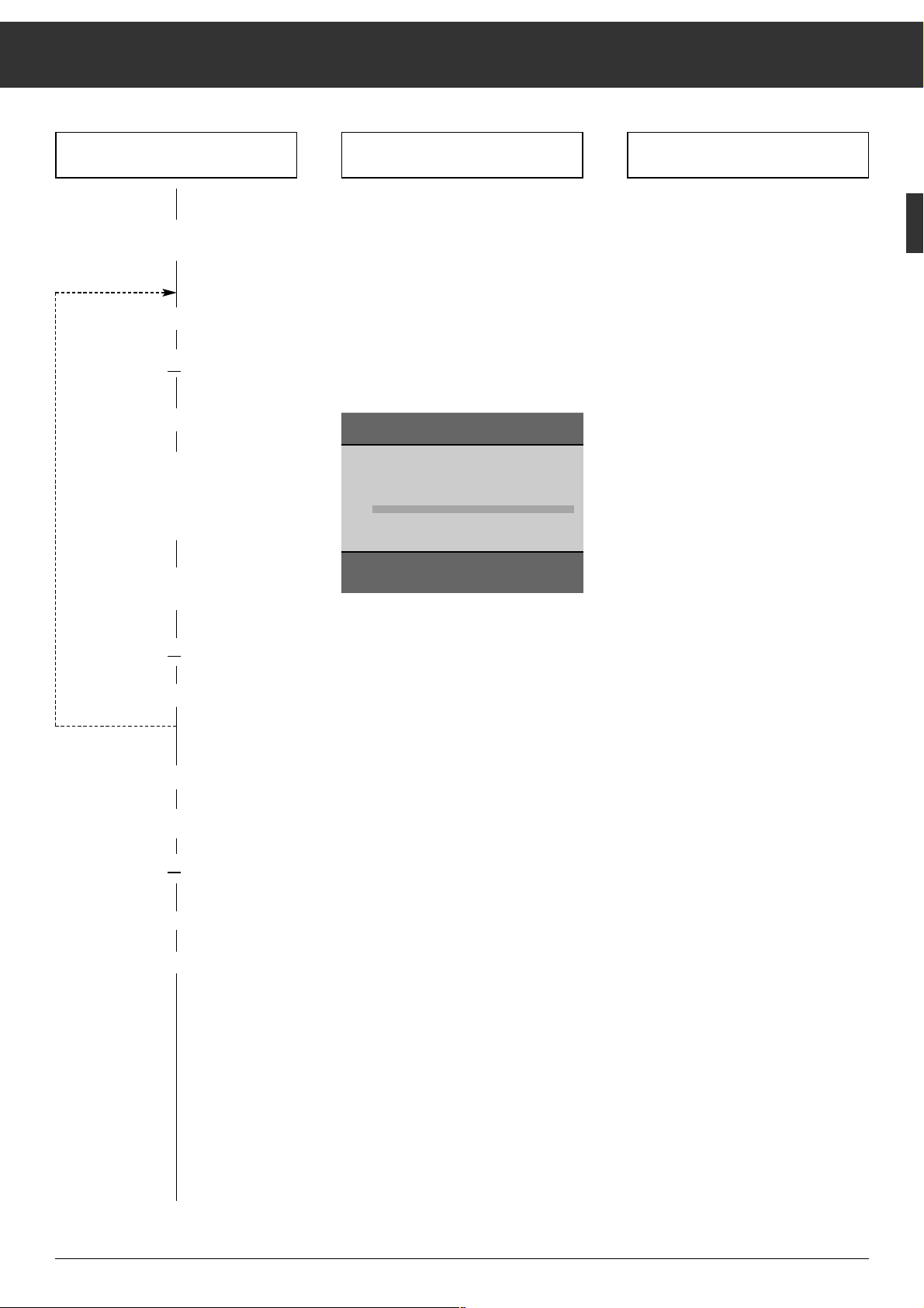
4. Selection between:
a) ATS station search
start ATS
a)
O
or
If a video recorder equipped with the
MEGALOGIC function is connected to
this TV set (the connection must be
made via the EURO-AV sockets –
socket AV2 on the TV set – with a fully
wired EURO-AV cable), the display
shown opposite will appear.
It is then possible to select between the
functions ”MEGALOGIC Upload....” and
”ATS”.
GRUNDIG ATS euro plus
ATS
MEGALOGIC Upload VCR1
Accept stations table
Select < >
ɶ
ʺ
Confirm OK
Terminate
Ǻ
GRUNDIG ATS euro plus
ATS
MEGALOGIC Upload VCR1
Accept stations table
Select < >
ɶ
ʺ
Confirm OK
Terminate
Ǻ
Page 7

ķ
7
Assigning Channel Positions
Press the ]button;
C changes to S (for special channel).
Press the
c
button;
the cursor jumps to the channel entry position.
Press the
0
and 8button. S 08 is visible in the data line.
It is also possible to select a channel by means of the manual
channel search.
To do this, press the
|
or ]button. The channel search is
started and will stop at each channel which can be received.
The TV set adjusts automatically the best possible picture
quality.
Press the
-
button.
A list of TV standards (norms) which can be received and
handled by the TV set is added to the display.
Press the
|
or ]button to highlight L/L'.
Press the
-
button.
The previous data line is displayed again. You now can give
the channel position a station name (abbreviation of max. 4
characters) by pressing the
c
button, or programme a
further programme position.
The TV set adjusts automatically the best possible picture
quality.
Allocating programme position 10 to special channel S 08,
SECAM L/L' norm, is now concluded.
Press the
.
button to return to the TV picture.
In difficult reception conditions, it may be necessary to
improve the picture quality by manual fine tuning.
Fine Tuning
Press the mbutton.
Press the
c
button until the highlighted cursor has reached
the 00 position (for fine tuning).
Use the
]
(63 steps) or
|
button (64 steps)
to adjust the optimum picture and sound quality.
B/G FM 5.5 (A2 Stereo)
B/G FM 5.5 (NICAM N, S, SF)
B/G FM 5.5 (NICAM D, DK, E)
L/L' AM 6.5 (Mono)
L/L' AM 6.5 (NICAM)
I FM 6.0 (NICAM)
D/K/K' FM 6.5 (A2 Stereo)
M FM 4.5 (Mono)
P 10 nS 08 +00 BR 3
Select
ɶɶ
ʺʺ
End standards entry AUX
Terminate
Ǻ
ATS euro plus – Update
If you have already found and stored programmes (channels)
with the "ATS euro plus" tuning system and wish to start another ATS euro plus search to update programme allocation in
the TV station table – for example, when the reception
conditions have changed because of newly offered programmes - select the menu point "Actualize TV-Stations" in the
Infocenter.
How to proceed:
Press the .button then the Obutton.
The "GRUNDIG Infocenter" appears on the screen.
Use the
|
button to select the menu line "Actualize TV
Stations".
Press the
O
button.
The automatic tuning system is started with the last settings
(language and country).
The newly found channels ("programmes") are added to the
existing channels in the TV station table and highlighted in
blue.
It is possible to shift the programmes to other programme
positions.
If a completely new run of the automatic tuning system is
required (e.g., when changing location or in the case of
connection to a cable TV system at a later date), start ATS as
described on page 5. In this case, the previous programme
position data is cleared.
Pressing the
.
button calls up the storage function
and pressing the
O
button stores the new programme
allocation into memory.
Assigning Channel Positions Manually
Exam
ple:
You wish to assign a programme transmitted on special
channel S 08 in SECAM L/L' norm to channel position 10.
How to proceed:
Select channel position 10.
Press the mbutton then the xbutton.
GRUNDIG Infocenter
D DK/N E F GB I NL P S SF
Special functions
Picture-menu
Timer/Security
TV-Station Table
Update TV-stations
Select
ɶ
ʺ
Activate OK
Terminate
Ǻ
Page 8
ķ
8
Changing the Channel Position Assignment
You will see this on the TV screen Explanations
ĻĻĻ
ŁŁ
The TV Station Table
The TV station table shows you the channel position assignment with the associated station names.
You can change this channel position assignment according
to your personal preferences and assign a station name to
stations without identification.
1. Call up the ”GRUNDIG Infocenter”
.
O
2. Select the ”TV-Station Table ”
line
|
|
a) Confirm
O
You can leave the TV station table by
pressing the .button. Your settings are automatically stored in
memory.
The following chapters
3.1 – 3.3 describe the different functions.
Select the desired function(s).
Press the following buttons on the
remote control
GRUNDIG Infocenter
D DK/N E F GB I NL P S SF
Special functions
Picture-Menu
Security/Timer
TV-Station Table
Update TV-Stations
Select
ɶ
ʺ
Activate OK
Terminate
Ǻ
GRUNDIG TV-Station Table
Prog Channel Station
1 C 06 ARD
2 C 24 ZDF
3 C 47 BR 3
4 C 40 SAT1
5 C 21 PRO7
6 C 59 BR 3
7 C 41 – – – –
8 C 53 RTL2
9 C 31 ZDF
10 C 32 ZDF
Select programme
ɶ
ʺ < >
Change name/channel OK
Move
n
Delete
n
Terminate
Ǻ
Page 9
ķ
9
Changing the Channel Position Assignment
Press the following buttons on the
remote control You will see this on the TV screen Explanations
3.2 Clear channel position data*
a) Select channel position
|,or ]
b) Clear programme position data
¢
(red button)
3.1 Changing the order of the
channels (shift or copy)*
a) Select channel position
|,or ]
b) Mark channel position
(shift:
¢ yellow button 1x;
copy**:
yellow button 2x)
c) Select new channel position
(shift; copy)
|,or ]
O
If you should not like the order of the
channels ("programmes), it is possible
to change the order at any time.
When shifting a channel, only the order
of the data on the channel positions will
be changed.
When copying a channel, the already
existing data of the marked channel
position will appear a second time on
the selected channel position (where
the cursor bar is located).
** Copying is only possible if the TV
set has a built-in SAT module.
If desired, repeat this procedure for
further channels ("programmes").
*
The steps 1 and 2 explained on page 8 must already be executed.
GRUNDIG TV-Station Table
Prog Channel Station
1 C 06 ARD
2 C 24 ZDF
3 C 47 BR 3
4 C 40 SAT1
5 C 21 PRO7
6 C 59 BR 3
7 C 41 – – – –
8 C 53 RTL2
9 C 31 ZDF
10 C 32 ZDF
Move
ɶ
ʺ < >
Confirm OK
Copy
n
Page 10
ķ
10
Changing the Channel Position Assignment
If you cannot find the desired name in
the list, you can enter your own. In
order to do so, press the cbutton
once, and using the |or ]button,
select the desired letter/number.
Press the
c
button to select the next
position.
Press the
.
button to complete this
procedure.
3.3 Enter a station name and channel
number or modify the existing one*
a) Select programme position
|,or ]
b) Visualize the data of the
programme position
O
d) Select existing station
name
c
e) Select new station name
|,or ]
f) Terminate
.
c) Enter channel number
1 … 0
If you store the channel number 00 on a
programme position, it is no longer
possible to select higher programme
positions with the |or
]
button
("return point"). If this return point is
placed on a programme position between 1 and 10, only the programme
positions 1 to 9 can be selected wit the
numeric buttons.
*
The steps 1 and 2 explained on page 8 must already be executed.
Press the following buttons on the
remote control You will see this on the TV screen Explanations
P 25 C n32 00 – – – –
Input channel number 0-9
Search mode
ɶ
ʺ
Norm AUX
Select position < >
Terminate
Ǻ
ARD
– – – –
BRT 1
BRT 2
CAN +
CAN 1
FILM
F 2
F 3
INFO
ITB
LIVE
P 25 C 32 00
n
ARD
Sel. station name
ɶ
ʺ
Norm AUX
Select position < >
Terminate
Ǻ
Page 11

ķ
11
The Remote Control Handset
Remote Control of a Video Recorder
The remote control handset of your television enables also
remote control of Grundig video recorders. Your specialized
dealer can tell you which video recorders are suited for this.
Press and hold down the
¢
VIDEO
button.
This switches the remote control handset into the video
recorder mode.
Then press the desired function button.
The following table shows you which buttons are to be used
for the different recorder functions.
ĵķ
(Numeric button 1) = Reverse picture search
ĶŁ
(Numeric button 2) = Forward picture search
•
( – i button) = Start recording
(
i + button) = Stop
ĵĵ
(Numeric button 7) = Fast rewind
ŁŁ
(Numeric button 8) = Fast forward wind
II
( – v button) = Pause
ı
( v + button) = Start playback
Ľ
(Numeric button 4) = Programme position –
Ń (Numeric button 5) = Programme position +
b
Switch to standby
and switch on with last selected
channel position.
®
Brightness
™
Colour contrast
,
Teletext mode ɫ TV mode
¢
R not used
¢
Shift programme position data when
allocating programme positions.
¢
Ȅ Time on/off
¢
Clear data when allocating programme
positions.
¢SAT Satellite receiver remote control
(press and hold down SAT button)
¢VIDEO
Video recorder remote control
(press and hold down VIDEO button)
1…0
Select programme position and
0
AV switch the set on from standby, or
select AV position
or
enter page numbers in Teletext mode.
m
Call up programme data.
Press and hold down for 4 seconds:
Access to ATS.
-
Preselect button for various functions.
.
Acces to Infocenter. After message
”Menu ɮOK”, press
“
OK
button.
]
Select programme step by step
(1, 2, 3 ...)
|
Select programme step by step
(...3, 2, 1)
When holding down the
]
or |button, the
station names will scroll on the TV screen. When
releasing the pressed button, the television switches to the selected programme position.
or
]
Move cursor (write position)
up
|
Move cursor down
“
OK
– Modify and activate various functions.
xc
Adjust volume,
or
xc
Move cursor to the left,
to the right.
¢ʀ
Switch sound on/off (mute)
Access to "Audio Menu"
1 2 3
4 5 6
7 8 9
P/C 0
ATS
AUX
AV
+
P
OK
P
ķ
+
-
R
SAT
VIDEO
TP 720
Page 12

ķ
12
Changing the Sound Setting ...
... with the Audio-menu
Calling up the Audio-menu
Press the
¢ʀ
button. The Audio-menu appears.
The "Sound effects" menu option is described on page 16, the
"Speakers" option on page 15.
Sound (stereo, two-channel sound, mono)
If your television is able to receive two-channel sound transmissions, for example when a film is broadcast in the original
sound track on sound channel A2 (Mono B or NICAM B), and
the synchronized version on sound channel A1 (Mono A or
NICAM A), you can select the version you want to hear (indication: Mono or NICAM).
Your television automatically switches to stereo if the programme is transmitted in stereo (indication: Stereo).
If stereo reception is poor, you can switch to "Mono" and thus
improve the sound quality (see example).
Example: To switch from "Stereo" to "Mono", highlight the
"Sound" function with the |or
]
button, then select
"Mono" with the
c
button.
If you wish to always receive a channel in mono, enter ",MO"
from the fourth position of the the station name on, for example, "ARD,MO" (see "Changing or renaming a station name" on
page 10).
If you can receive TV programmes in the SECAM L NICAM
colour standard, make sure that one of the indications
NICAM A, NICAM B, NICAM Stereo or NICAM is shown in the
"Sound" line of the Audio menu.
If this should not be the case, check whether the SECAM L
NICAM standard has been set on the programme position
concerned.
To do this, quit the Audio menu and call up the data of the
programme position to be checked by pressing the
m
button.
If you wish to assign a different TV standard to this programme position, follow the example given on page 7 in the
chapter "Assigning Channel Positions Manually".
Indication of the sound transmission mode
Each time the station changes the sound transmission mode
(e.g., from mono to stereo), the mode is displayed for
approx. 4 seconds.
Audio-menu
Sound effects Off
Sound Stereo
Headphones Stereo
Equalizer
Speakers
Select
ɶ
ʺ Change < >
Terminate Ǻ Sound mute
ʀ
This indication takes also place when changing the programme, however only if the mode differs from the mono mode.
With the
.
button, the indication can permanently be
displayed. Press .once again to remove the display.
Equalizer
For individual tone control, the television is provided with a
seven-band-equalizer.
In the mono, stereo, two-channel sound, and pseudo
surround sound modes, it is possible to boost or cut the
frequencies 0.1 – 0.3 – 0.5 – 1 – 2 – 4 and 12 kHz.
Call up and display the "Equalizer" function in the same way
as switching from stereo to mono (see example in "Sound"
chapter).
Boost or cut the frequencies with the |or ]button.
Press the
-
button to return to the basic values.
Headphones
For headphones, change the settings in the Audio Menu as
described in the previous chapters.
Connection
Insert the headphones plug (6.3 mm ø jack) into the headphones socket.
Changing the headphones volume
Press the -button to display the AUX menu.
Change the setting with the
xc
buttons.
Equalizer
max
0
y
z
z
n
n
z
z
min
kHz
→
.1 .3 .5 1 2 4 12
Select < > Change
ɶ
ʺ
Terminate Ǻ Reset
AUX
VIDEO IN L AUDIO IN R
-
PROGRAM +
m
Page 13

ķ
13
Loudspeaker Systems for the Other
Dolby Operating Modes
If you cannot install four loudspeaker boxes, you can still use
the following Dolby operating modes:
Dolby Phantom, or
Dolby 3 Stereo, or
Pseudo Surround.
2. Loudspeakers with Dolby 3 Stereo
3. Loudspeakers with Dolby Phantom and
Pseudo-Surround
With the operating modes 2 and 3, it is not possible to get the
optimum sound impression such as with Dolby Surround Pro
Logic.
TV loudspeaker or
additional centre loudspeaker
TV loudspeaker
Stereo front box, left
Stereo front box, right
Important Information
This system has been developed to allow you to enjoy the
dramatic realism and impact of multi-channel Dolby movie
theater sound in your own home.
The Dolby Surround Pro Logic signal comprises:
Stereo channel (right/left)
Centre channel
Surround channel
With Dolby Surround, the sound created by the conventional
stereo channels (right/left) is improved by an additional
centre channel which makes it possible to precisely locate the
origin of the individual tones.
This centre channel fixes the voices (dialogues) in the sound
centre (corresponding to the picture).
The Surround channel (also called back channel) completes
the sound system. Two additional loudspeakers which are
located behind the listener create the actual "Surround"
sound, that is the realistic sound atmosphere (depth of
space, special effect sounds). The listener is "placed inside
the action".
With the Dolby Surround Pro Logic system, the sound/picture sources can be laser discs, video cassettes, and television broadcasts.
Loudspeaker Systems for
Dolby Surround Pro Logic
To get the optimum sound quality from the Dolby Surround
Pro Logic system, two Surround speaker boxes and two front
boxes or two Surround boxes and one centre box are required.
1. Loudspeakers with Dolby Surround Pro Logic
The front boxes should be placed at a distance of approx.
1.5 m from the television.
Dolby Surround Pro Logic
TV loudspeaker or
additional centre loudspeaker
Surround box
Surround box
Surround box
Surround-Box
TV loudspeaker or
front box, left
TV loudspeaker or
front box, right
Under license from Dolby Laboratories Licensing Corporation.
"DOLBY" and the double-D symbol ij are trademarks of Dolby
Laboratories Licensing Corporation.
Page 14

ķ
14
Dolby Surround Pro Logic
Connecting the Loudspeaker Boxes
Connecting the surround boxes with 4 Ohm
nominal impedance.
AV2
VIDEORECORDER
AV1
RECEIVER / DECODER
ʐ
INPUT-SAT
950...2050MHz
14/18V 0,35A
8Ω
ǁ
Surround
AUDIO
OUT
L
R
Center
L
R
Connecting the front stereo boxes (8 Ohm) and
the centre loudspeaker (8 Ohm)
AV2
VIDEORECORDER
AV1
RECEIVER / DECODER
ʐ
INPUT-SAT
950...2050MHz
14/18V 0,35A
8Ω
ǁ
Surround
AUDIO
OUT
L
R
Center
L
R
HiFi output L AUDIO-OUT R
You can connect a hifi stereo system to these phono sockets
to reproduce the television sound via the hifi system instead
of the front boxes.
If you wish to switch off the loudspeakers of the TV set, you
must insert the speaker plugs into the sockets L and R.
Centre loudspeaker
Front box, right Front box, left
Page 15

ķ
15
Dolby Surround Pro Logic
Audio Menu
Press the ¢ʀbutton to call up the audio menu.
The "Speakers" menu option
In the "Speakers" submenu, you must indicate whether there
are external loudspeakers connected to the television. If yes,
you must indicate the loudspeaker system.
For this:
Pess the |button until "Speakers" is highlighted in colour.
Press the cbutton to call up the speakers menu.
A random configuration (graphical representation of a loudspeaker arrangement) is displayed.
Press the
c
button to display a selection of speakers.
You can select between:
– No external speakers.
– Centre and Surround speaker boxes
(see illustration on page 13; 3. Loudspeakers with ...).
– Front speaker boxes only
(see illustration on page 13; 2. Loudspeakers with ...).
– Front and Surround speaker boxes
(see illustration on page 13; 1. Loudspeakers with ...).
– Surround and centre speaker boxes
(see illustration on page 13; 1. Loudspeakers with ...).
Repeatedly press the |button until the desired configuration is displayed.
Press the
.
button.
Speakers
ļļ
Loudspeaker
no ext. speakers
Balance Surround
Front
Rear Level Front+Surround
Master Level Centre/ Rear
Test signal
Select
ɶɶ
ʺʺ
Change
ɼɦ
Terminate Ǻ
TVTV
Adjusting (balancing) theTV loudspeakers and
the connected speaker boxes to each other
After having selected the desired configuration, all loudspeakers and speaker boxes must be adjusted to each other. In
the following example "Front/Surr.".
For this, the "Test Signal" option in the "Speakers" menu is
provided.
Highlight the "Test-Signal" line with the |button and switch
the function on with the
c
button.
You will hear the test signal (noise) from the loudspeakers.
The test signal is emitted in the following order:
Balance (right/left)
Centre level
Surround level
The cursor bar indicates which loudspeaker (box) is currently
emitting the test signal.
It is possible to adjust only that
speaker configuration which
is currently highlighted in the menu.
Adjusting the balance of the front speaker boxes
Wait until "Balance" is highlighted.
Then, use the
x
and cbuttons to adjust the front boxes so
that they have the same sound level (emit with equal volume
level).
During the setting procedure, the cursor bar remains on the
"Balance position".
The sound signal is emitted only by the front speaker boxes.
When releasing the
x
or cbutton, the cursor bar jumps to
the next position in the test signal order.
Speakers
ļļļ
Loudspeaker Front+Surround
Balance
nnnnn
y
nnnnn
Centre Level
nnnnnnnnnnn
Rear Level
nnnnnnnnnnn
Master Level
nn
n
nnnnnnnn
Test Signal on
ĻĻ
Select
ɶɶ
ʺʺ
Change
ɼɦ
Terminate Ǻ
TVTV
ŁŁ
Page 16

ķ
16
Centre level (for Dolby Surround Pro Logic)
Rear level
Adjust in the same way as for the "Balance "menu option.
Master volume
After having balanced (equal volume levels) all loudspeakers
and speaker boxes, it is possible to adapt the global volume
level to the room requirements.
"Volume" is manually to be selected.
The cursor bar does not
automatically jump to this position.
Select with |or ], change the setting with
x
or c.
After having terminated all adjustments, the test signal must
be switched off.
Press the
.
button (terminate) to return to the Audio menu.
Press again to return to the TV picture.
Audio Menu
Sound effects
It is possible to add a selection of sound effects to each configuration (graphical representation of loudspeaker arrangement).
For this:
Press the
¢ʀ
button to call up the Audio menu.
The cursor bar marks the "Sound effects" option.
Press the
c
button to display the offer of available sound
effects. Only the sound effects shown in black letters can be
selected. The sound effects which can be selected depend on
the used loudspeakers configuration.
Press |or ] to select the desired sound effect and confirm by pressing the
O
button.
Dolby Pro Logic, Dolby 3 Stereo, Dolby Phantom
Dolby-Surround adjustments make only sense if the sound is
received in stereo.
Sound effects DISCO, CONCERT, CHURCH
In addition to the Dolby Surround modes and the Pseudo
Surround mode, the above sound effects are available.
It is possible to use these functions with Dolby Surround,
stereo or mono broadcasts.
When selecting one of the sound effect functions, the last
selected configuration with the associated Dolby mode is
used.
Equalizer in Dolby surround mode
In the Dolby modes and with the sound effects, the equalizer
function serves as tone balance control.
The Dolby signal is normed and has a linear characteristic.
See illustration.
A correction is normally not required.
The sound balance control should only be used to make corrections to compensate for acoustic irregularities of the
room.
To do this, call up the Audio menu by pressing the
¢ʀ
button.
Select "Equalizer" with the |button.
Activate the "Equalizer" function with the Obutton.
Change the frequencies as desired with the |or ]button.
Press the -button if you wish to reset the frequencies to
their basic values (linear).
Equalizer
max
0
nnnnnnn
min
Bass Treble
Select < > Change
ɶ
ʺ
Terminate Ǻ Reset
AUX
For example, if you receive a programme in stereo, the
station transmits a corresponding signal and the TV set
switches automatically to stereo sound.
For Dolb
y Surround Pro Lo
gic, the TV stations are presently not yet tansmitting an additional VPS signal for
automatic switching to this Dolby mode.
For this reason, we recommend you to search in a TV
programme guide, which contains information about
Dolby Surround, for these programmes, and to adjust
your TV set accordingly at the times when these programmes are broadcast.
Dolby Surround Pro Logic
Audio-menu
Sound effects off
Sound Stereo
Headphones Stereo
Equalizer
Loudspeakers
Select
ɶ
ʺ Change OK
Terminate Ǻ Sound mute
ʀ
Stereo Mode
off
DOLBY PRO LOGIC
DOLBY 3 STEREO
DOLBY PHANTOM
PSEUDO SURROUND
DISCO
CONCERT
CHURCH
Page 17

ķ
17
Adjusting the Picture
Contrast and Sharpness
Press the .then the Obutton.
The "GRUNDIG Infocenter" is displayed.
The "Picture-menu" line is marked in red.
Press the
O
button.
The "Picture-menu" is displayed.
Select "Contrast", "Sharpness" or "Tint" by pressing the |or
]
button.
The "Tint" menu option is only displayed and can be adjusted
with NTSC standard broadcasts.
Correct the setting by pressing the
x
or cbutton.
When leaving the picture menu by pressing the
.
button, all
settings are automatically stored in memory.
Brightness and Colour Contrast
Press on the – or + side of the corresponding rocker button
(v, i) until the desired value is reached.
Brightness with the
®
button.
Colour contrast with the
™
button.
Corresponding scales are displayed on the picture screen.
The changed value is indicated.
The last set value for contrast, colour contrast and brightness
is automatically stored in memory by:
switching from a normal to the AV programme position;
switching from one AV programme position to another;
switching to standby;
switching off with the mains switch.
The values are checked before storing.
If they have been reduced in such a degree that a reasonable
picture impression is no longer obtained, the factory-preset
settings (optimum values) will reappear when switching the
set on again.
This television was tested with maximum contrast to
verify the reliability of all components.
It is advisable to turn down the contrast to offer you the
best picture quality depending on lighting conditions or on
the location where your TV is set up.
Picture-menu
Contrast
–
Sharpness
–
Select
ɶɶ
ʺʺ
Change < >
Terminate
Ǻ
Switching the Picture Format
If the television is used with a satellite receiver in the PAL
plus TV standard with a 16:9 picture format, it is necessary
to switch the conventional picture format 4:3 to 16:9.
Press the
-
button; the AUX menu will be displayed.
Select the "Format" line with the
|]
buttons.
Select the format with the xor cbutton.
Press the
.
button to remove the AUX menu from the
screen.
AUX
Headphones
AV AV 1
Record Off
Format Standard 4:3
Select
ɶɶ
ʺʺ
Change < >
Activate OK Terminate
Ǻ
Page 18

ķ
18
Teletext
1…0
Select pages 100-899
Press
-
to display dialogue line
Display:
Enlarge character height
Bypass
waiting times
(actualmode)
Call up
sub-page
Reveal
answer
Stop
page
Select the desired function with the xor
c
button.
Activate with the
“
OK
button.
ķ
ʄʄ
ķX /00 ķ? STOP
.
Call up overview page
,
Teletext mode ɫ TV mode
¢(blue) Switch to next block
¢(yell.)
Switch to next group with passage to
next block.
¢(grn) Switch to next page with passage to
next group.
¢(red) Return
Floftext
The coloured buttons lead
to the topics shown in the
dialogue line.
1 2 3
4 5 6
7 8 9
P/C 0
ATS
AUX
AV
ķ
R
+
P
OK
+
-
P
SAT
VIDEO
TP 720
Page 19

ķ
19
Teletext Mode
General
Teletext is an additional information that is broadcast by the
TV station along with your TV programme.
The built-in Teletext decoder of your set enables you to display this additional information on the screen.
Teletext is transmitted in the form of texts or graphic representa-tions, or as subtitles to the TV programme.
The latter is intended to help the hard of hearing.
By means of information pages and dialogue lines, Teletext
operation is made very easy. The indication in the dialogue
lines denote the functions with the allocated buttons to use.
TOP/FLOF-Teletext
TOP (Table of Pages) and FLOF (Full Level One Features)
are new methods for quick and easy selection of Teletext
pages.
Using TOP and FLOF you can select Teletext pages without
knowing the page numbers. This is possible since all Teletext
pages are transmitted ordered according to topics - also called blocks - as if they were in a "filing box".
For example, the latest news are grouped in the block "Actualities". Further topics are for example the blocks "Sports", "TV
Programmes" and "Service". In the case of TOP Teletext, the
blocks are subdivided into several groups, eg: "Actualities"
into the groups politics, economics, culture, etc. Within the
groups you will find the normal Teletext pages.
With the help of the user’s guide on the picture screen, Teletext operation is very simple and fool-proof. A coloured command line is visible on the bottom edge of the screen. The
shown colours are the same as those on the remote control
handset. In the case of TOP operation, the yellow field denotes the selected block and the following group. The blue field
indicates the next block.
The blue button of the remote control handset is used to
advance from one block to the other, the yellow button is
used to go from one group to the next, and the green button
is used to go to the next page. To return to the page the red
button is used.
In the case of FLOF operation, a choice of subjects appears in
coloured characters. The required subject is selected by pressing the corresponding coloured button on the remote control.
In this way, TOP and FLOF lead you quickly, easily, and surely to the goal - the desired Teletext page.
If no TOP or FLOF Teletext is transmitted by the station, a red
colour bar with a - and a green colour bar with a + will
appear in the commentary line.
Note
If the aerial signal is poor, eg: noisy, it may happen that the
Teletext pages are not correctly reproduced. - If fine tuning
on the TV set brings no improvement, we recommend you to
let check your aerial system by a specialist.
What you should know
For the Teletext mode "Top", additional information is required from the TV station. - For this reason, after having
switched on the TV set or after having changed the programme, please wait some moments until the GRUNDIG Top
decoder has read the data into its memory and all of the information is at your disposal.
By pressing the button
, you can immediately return from
each operating mode back to normal TV operation.
Please observe the currently displayed user’s guide with the
dialogue lines on the bottom edge of the picture screen.
WeatherNewsSportTV Guide
yellowgreenred
blue
- +
NEWS
next group
SPORTS
next block
Page 20

ķ
20
Teletext Mode
Operation
Using the numeric buttons 1…0, select a channel whose
teletext pages you would like to view.
Switching Teletext On/Off
Press button , on the remote control handset.
The contents page 100 or the Teletext page viewed last will
appear.
Press button
, - Teletext is switched off.
TOP Mode
A red, green, yellow and blue field is shown at the bottom of
the screen. Buttons of the same colors are found on the
remote control.
With the red
¢ button of the remote control, you scroll back-
wards one page.
With the green
¢ button of the remote control, you scroll to
the next available page (with overrun to the next group).
With the yellow
¢ button of the remote control, you switch
to the next group. After the last group of the selected block,
your are automatically taken to the next block (overrun).
With the blue
¢ button of the remote control, you switch
from block to block.
Selecting Pages
Select the number of the desired page as three figures with
the numbered buttons
1…0
.
– The number of the selected page appears at the top of the
TV screen and the page appears after a short time.
The last viewed page can be selected by pressing the
m
button.
Overview Page/Programme Preview
You can switch directly to the programme preview (with TOP
Text) or the overview page of the station you are currently
viewing.
Press the
.
button.
The programme preview block or the overview page appears.
Multiple Pages/Page Stop
Several subpages can be combined under a single page number and these pages are automatically scrolled at an interval
determined by the television station.
The presence of subpages under a single page number is
indicated by, for example, 3/6 beneath the time, which means
that you are looking at the 3rd page of a total of 6 pages.
If you want to look at a page for a longer period of time,
press the
-
button.
The dialogue line appears.
Select the STOP symbol with the
x
or cbutton.
Press the
“
OK
button.
"STOP" appears at the top of the screen. The contents of the
page shown are kept on the screen and are no longer updated
or switched to other subpages.
Press the
“
OK
button.
The STOP function is cancelled and the current subpage
appears.
It is also possible to perform this function with the
x
button
without calling up the dialogue line.
Page 21

ķ
21
Teletext Mode
This function can also be used to bypass waiting times while
the teletext decoder searches for a page. When the page has
been found, the indication P143, for example, appears in the
info line.
Call Up a Subpage Directly
Press the -button (the dialogue line appears).
Select the /00 symbol with the
x
or cbutton.
Press the
“
OK
button.
The selected page number, e.g., S155/---- appears in the info
line.
Enter the four-place subpage number that you want to call up
with the numeric buttons, for example, the second page,
sequence 0002. The desired subpage is sought.
While the page is sought, you can watch television. For this,
select the
ķX symbol with the
x
or cbutton.
Press the
“
OK
button.
The regular programme is still visible and the teletext symbol
appears at the top of the screen.
As soon as the page is found or updated, it is displayed on
the picture screen.
Cancelling the function:
Press the
-
button (the dialogue line appears).
Press the
“
OK
button.
The function is cancelled.
It is also possible to perform this function with the left side of
the
™ rocker button without calling up the dialogue line.
Page Catching
This function allows you to select a teletext page without
entering the corresponding page number.
You can select desired teletext pages from the overview
pages (pages designated with a three-digit page number).
Press the |or ] button.
Page-Catching" appears in the upper part of the screen.
The first or last page number of the overview is highlighted
by a frame (cursor)
Press the |or ] button to move the cursor to the desired
page number.
Press the
“
OK
button.
The desired page appears on the screen.
Double Character Size
Press the -button (the dialogue line is displayed).
With the
x
or cbutton, select the ķʄ symbol.
Repeatedly pressing the
“
OK
button doubles the character
size in the following order:
Upper half of the picture,
lower half of the picture,
return to normal picture.
It is also possible to perform this function with the right side
of the
™ rocker button without calling up the dialogue
line.
Reveal Answer
This function can be used on certain teletext pages to reveal
the solution of riddles, or for programming a video recorder
via VPS times.
Press the
-
button (the dialogue line appears).
With the
x
or cbutton, select the ķ? symbol.
Press the
“
OK
button.
The hidden information is revealed.
Press the
“
OK
button.
The reveal function is cancelled.
It is also possible to perform this function with the
c
button
without calling up the dialogue line.
Watching Television During Teletext Mode
Updating a page –
Bypassing waiting times
Certain teletext pages are continually updated, for example,
stock market reports, sports announcements, and the latest
news.
If you want to watch television and stay informed at the same
time, first select a page of your choice, then
press the
-
button (dialogue line is displayed).
With the
x
or cbutton, select the ķX symbol.
Press the
“
OK
button.
The regular programme is still visible and the teletext symbol
appears at the top of the screen.
If, for example, P143 appears in the info line, then
press the
“
OK
button.
The teletext page appears with the updated information.
Page 22

ķ
22
Convenient Functions
Press the following buttons on the
remote control You will see this on the TV screen Explanations
ĻĻĻ
Security/Timer Functions
With these functions you can block programmes unfit for
children, block all TV programmes, and
enter a switch-off time (Sleep Timer) and/or a switch-on time
(Wake up Time).
By pressing the .button, you can
return to the current programme at
any time.
The following chapters
3.1 – 3.4 describe the four different
Security/Timer functions.
Select the function that you need.
ŁŁ
1. Call up the "GRUNDIG Infocenter"
.
O
2. Select the "Security/Timer" line
|
a) confirm
O
GRUNDIG Infocenter
D DK/N E F GB
I NL P S SF
Special functions
Picture-menu
Timer/Security
TV-Station Table
Update TV-Stations
Select
ɶ
ʺ
Activate OK
Terminate
Ǻ
GRUNDIG Security/Timer
Security Code – – – –
Lock program unfit for
children no
All programmes blocked no
Sleep Timer – – : – –
Wake-up-Time – – : – –
Wake-up-Prog TV 1 ARD
Select
ɶ
ʺ
Change OK
Terminate
Ǻ
Page 23

ķ
23
Convenient Functions
You can block the broadcasts at any
time.
If now a programme unfit for children is
being broadcast, the table opposite
appears on the screen (example RTL).
Memorize the stored security code!
If you should forget the code, switch to
a non blocked programme position, call
up the Security/Timer page and press
the
O
. button. Then refer to the key
on the last page (cover) which will help
you.
After the television has been turned off
(automatically or with the
b button), it
cannot be used by unauthorized persons.
Memorize the stored security code!
If you should forget the code, refer to
the key on the last page (cover) which
will help you.
ŁŁ
3.1 Blocking programmes unfit
for children
*
a) Enter code as four places.
O
1 … 0
O
b) Block programme: yes
x
c) Switch to TV mode.
.
3.2 Block all programmes
*
a) Enter code as four places.
O
1 … 0
O
b) Select "yes" in the "Block all
programmes" line
|
xor c
c) Enter switch-off time (from...)
(if desired)
|
O
*
The steps 1 and 2 explained on page 22 must already be executed.
Press the following buttons on the
remote control You will see this on the TV screen Explanations
GRUNDIG Security/Timer
Security Code 1111
Lock program unfit for
children yes
All programmes blocked no
Sleep Timer – – : – –
Wake-up-Time – – : – –
Wake-up-Prog TV 1 ARD
Select
ɶ
ʺ
Change < >
Terminate
Ǻ
GRUNDIG Security
Security Code
n
– – – –
RTL blocked !
Program unfit for children
Input 0-9
Select programme position
ɶ
ʺ
GRUNDIG Security/Timer
Security Code 1111
Block program unfit for
children no
All programmes blocked yes
from – – : – –
Wake-up-Time – – : – –
Wake-up-Prog TV 1 ARD
Select
ɶ
ʺ
Change < >
Terminate
Ǻ
Page 24

ķ
24
Convenient Functions
The television switches automatically
off at the entered switch-off time. When
then switching on again, the table
shown opposite will appear. The TV set
can only be used again when you enter
your personal identification code.
The television automatically switches
off (standby) at the set time.
With the "Wake-up Prog" function (last
menu line) you select that
programme
position with the programme of which
you wish to be woken up.
Select ”Wake-up Prog” with the |or
]
button.
Press the
O
button.
Select the desired programme with the
|
or ]button.
Press the
O
button.
So that the TV set can switch on at the
preselected time, if must be switched to
standby (not off with the mains switch).
1 … 0
O
d) Switch to TV viewing mode.
.
3.3 Entering a switch-off time
(Sleep Timer)
*
a) Select "Sleep Timer".
|
O
b) Enter switch-off time.
1 … 0
O
c) Switch to TV mode.
.
3.4 Enter switch-on time
(Wake-up Time)
*
a) Select "Wake-up Time"
|
O
b) Enter switch-on time.
1 … 0
O
c) Switch to Tv mode.
.
*
The steps 1 and 2 explained on page 22 must already be executed.
Press the following buttons on the
remote control You will see this on the TV screen Explanations
GRUNDIG Security/Timer
Security Code – – – –
Block programs unfit for
children yes
All programmes blocked no
Sleep Timer – – : – –
Wake-up-Time – – : – –
Wake-up-Prog TV 1 ARD
Select
ɶ
ʺ
Change OK
Terminate
Ǻ
GRUNDIG Security
Security Code
n
– – – –
Programme locked !
Input 0-9
GRUNDIG Security/Timer
Security Code – – – –
Block programs unfit for
children ja
All programmes blocked nein
Sleep Timer – – : – –
Wake-up-Time – – : – –
Wake-up-Prog TV 1 ARD
Select
ɶ
ʺ
Change OK
Terminate
Ǻ
Page 25

ķ
25
Convenient Functions
Special Functions
Calling up the Special Functions menu
Call up the GRUNDIG Infocenter by pressing the .button
then the
“
OK
button.
Press the cursor button ]to highlight the "Special functions" line.
Press the
“
OK
button.
Calling up the "Settings" menu
Press the
“
OK
button.
The "Volume" line is highlighted.
Volume
If you receive a programme whose volume deviates from
other channels (too loud or too low), you can adjust the volume.
Change the volume with the
x
or cbutton. Lautstärke
ändern. Only the volume of the programme currently being
selected is changed.
Colour match
Select "Colour match" with the |button.
The line appears highlighted in blue.
GRUNDIG
Settings
Volume P 1
–I–
Colour match P 1
–I–
Switch on with Programme 1
Pict./sound options off
MEGALOGIC info on
Select
ɶɶ
ʺʺ
Change < >
Terminate
ǺǺ
GRUNDIG
Special Functions
Settings
AV settings
IR-Dataprogrammer
MEGALOGIC Download
Transfer of TV stations table
Service
Select
ɶɶ
ʺʺ
Activate OK
Terminate
ǺǺ
Use xor c button to change colour match. Only the colour
match of the programme currently being viewed is changed.
Press the
.
button to return to the TV picture.
Switch on with ...
If you use the TV set frequently as AV monitor, for example
together with a camera as supervisory system, you can use
this function to give priority to the AV programme position.
That means that after switching on the set the AV programme
position will appear instead of the P1 programme position.
Select with
|
and change the setting with xor c.
Picture/sound scale
Press the |button to highlight the "Picture/sound scale"
line.
Press the
x
or cbutton to display (on) or not (off) the res-
pective scale on the picture screen, such as
MEGALOGIC Info
With the MEGALOGIC function, it is possible to display information about the connected video recorder on the picture
screen.
Independent of the TV mode, you will be informed by brief
displays about the current video recorder function.
For example: tansfer of TV stations table, playback, recording, fast forward wind, etc.
Press the
|
button to highlight the MEGALOGIC line.
Use the
x
or cbutton to switch the information display on
and off.
If no video recorder with MEGALOGIC functions is connected, select ”off”.
min........ .........max
Volume
Page 26

ķ
26
Special Functions
Calling up the Special Functions menu
Call up the GRUNDIG Infocenter by pressing the .button
then the
“
OK
button.
Press the cursor button ]to highlight the "Special functions" line.
Press the
“
OK
button.
AV settings
The AV settings menu is described from page 27 on.
IR-Dataprogrammer/Service
The IR-Dataprogrammer and Service functions are intended for the specialised dealer only. The Service function is
protected by a security code.
GRUNDIG
Special Functions
Settings
AV settings
IR-Dataprogrammer
MEGALOGIC Download
Transfer of TV stations table
Service
Select
ɶɶ
ʺʺ
Activate OK
Terminate
ǺǺ
Transfer of the TV stations table from the TV
set to the video recorder (VCR)
The TV set is provided with the MEGALOGIC system.
In connection with a video recorder which is provided with
the same system, operation of the two sets becomes very
convenient.
It is possible to transfer the data of the channel positions
(stored channels) from the TV set to the video recorder.
Programming the channel positions on the VCR then is no
longer necessary.
After transferring the data, you can immediately record the
programme from the TV set on the video recorder.
For this, the TV set (socket AV2) and the video recorder
(Euro-AV socket) must be connected by means of a
Euro-AV cable (all pins used).
Press the
|
button to highlight the "Transfer of TV stations
table" line then press the
“
OK
button.
During data transfer, the message ”Transfer of stations table”
as well as the channel position number and the station name
are displayed.
When data transfer is completed, the TV set is automatically
switched to TV mode.
Convenient Functions
Page 27

ķ
27
Connection Capabilities and Operation ...
Call up the AV settings menu as follows:
Press the .then the
“
OK
button; the "Infocenter" menu will
be displayed.
Press the ]button; the line "Special Functions" is highlighted
by a colour bar.
Press the
“
OK
button; the "Special Functions" menu will be
displayed.
Press the |button; the line "AV settings" is highlighted by a
colour bar.
Press the
“
OK
button; the "AV settings" menu will be dis-
played.
Playback from a Video Recorder
Connection
Connect the video recorder to the AV 2 socket.
Operation
Call up the "AV settings" menu (see above).
Press |or ]to select "AV2" (highlight in colour).
Press
x
or cto select between "Video" and "SVIDEO"
(according to connected video recorder).
Leave the menu by pressing
.
.
Start playback on the video recorder.
You will see the video playback on the picture screen and
briefly the message and respectively.
...Video-Recorder an Antennenbuchse
Programme the playback channel (between 30 and 40) of the
video recorder on a free channel position (e.g. P16) as
described in the chapter "Assigning channel positions
manually".
Turn the channel selector in the back of the video recorder to
the left or to the right (see operating instructions of the video
recorder) until the video playback from the recorder appears
on the picture screen.
Use the ATS systems or the automatic channel search only if
the playback channel of the video recorder is set to the channel centre (finetuning 0).
AV 2 SVIDEOAV 2 VIDEO
The TV set is provided with a number of different sockets.
You can connect various external units to these sockets, such
as video recorder, SAT receiver, video camera, etc., and perform functions such as recording, playback, copying, etc.
Before you can do this, the external unit must be adapted to
the TV set. For this, the "AV Connections" menu is provided.
... for Video Recorder
GRUNDIG
AV settings
Decoder Off
AV 1
AV 2 SVIDEO
AV 3
Identify Auto
Select
ɶɶ
ʺʺ
Change < >
Terminate
ǺǺ
AV2
VIDEORECORDER
AV1
RECEIVER / DECODER
ʐ
INPUT-SAT
950...2050MHz
14/18V 0,35A
8Ω
ǁ
Surround
AUDIO
OUT
L
R
Center
L
R
EURO-AV
AUDIO
Page 28

ķ
28
Connection Capabilities and Operation ...
… for Camcorder (VHS, Video 8)
… for S-VHS Video Recorder, S-VHS Camcorder
or Hi8 Camcorder
Playback
Connect the camera to the AV 2 socket.
Call up the "AV Settings" menu (see page 27).
Select "AV 2" and "S VIDEO".
Press .to leave the menu.
Start playback on the camcorder.
Playback from the camcorder is visible on the picture screen.
AV2
VIDEORECORDER
AV1
RECEIVER / DECODER
ʐ
INPUT-SAT
950...2050MHz
14/18V 0,35A
8Ω
ǁ
Surround
AUDIO
OUT
L
R
Center
L
R
Playback
Connectin
g the video signal
Connect the VIDEO IN socket with an appropriate cable to the
corresponding video socket of the camcorder.
Connecting the sound signal
Connect the L AUDIO IN R sockets with the audio sockets of
the camcorder. For mono playback, connect to the L AUDIO
IN socket to the respective audio socket of the camcorder.
Operation
Call up the "AV setting" menu (see page 27).
Select AV3 and ”Auto”
In the case of distortions, select "off".
Press
.
to quit the menu.
Start playback on the camcorder.
Playback from the camcorder is visible on the picture screen.
GRUNDIG
AV settings
Decoder off
AV 1
AV 2 SVIDEO
AV 3
Identify Auto
Select
ɶɶ
ʺʺ
Change < >
Terminate
ǺǺ
VIDEO IN L AUDIO IN R
-
PROGRAM +
m
Page 29

ķ
29
Connection Capabilities and Operation ...
... for Satellite Receiver
Connection
Connect SAT receiver to the AV 1 socket.
O
peration
Select "AV 1".
Switch on the SAT receiver.
Press and hold down the ¢SAT
button and enter the number
of the desired programme position of the satellite receiver
with the numeric buttons
0…9
.
This TV set is prepared for satellite reception. As extension
kit, the module SER 6350 is provided. Ask your specialized
dealer for further details.
AV2
VIDEORECORDER
AV1
RECEIVER / DECODER
ʐ
INPUT-SAT
950...2050MHz
14/18V 0,35A
8Ω
ǁ
Surround
AUDIO
OUT
L
R
Center
L
R
EURO-AV EURO-AV
... for Descrambler (Decoder)
Connection
Connect decoder to AV 1 socket.
Operation
Call up the "AV settings" menu (see page 27).
Select "AV 1" and "Decoder".
The indication P 10 means Programm position 10 is selected.
Leave the menu.
If "Decoder" or "Sound" is selected in the "AV settings"menu,
"Auto" is always activated (factory presetting).
Normally, this needs not be changed.
However, with external units which do not meet the technical
standard of this TV set, it may be necessary to make a different setting. If this should be the case, contact your specialized dealer.
If a video recorder is connected to the AV2 socket, the
decoder should be connected to the video recorder.
GRUNDIG
AV settings
Decoder AV1
Settings P 10 Auto
Sound Auto
AV 1
AV 2 SVIDEO
AV 3
Identify
Auto
Select
ɶɶ
ʺʺ
Change < >
Terminate
ǺǺ
AV2
VIDEORECORDER
AV1
RECEIVER / DECODER
ʐ
INPUT-SAT
950...2050MHz
14/18V 0,35A
8Ω
ǁ
Surround
AUDIO
OUT
L
R
Center
L
R
Page 30

ķ
30
Connection Capabilities and Operation ...
... for Video Recorder ... for Satellite Receiver ... for Descrambler (Decoder)
AV2
VIDEORECORDER
AV1
RECEIVER / DECODER
ʐ
INPUT-SAT
950...2050MHz
14/18V 0,35A
8Ω
ǁ
Surround
AUDIO
OUT
L
R
Center
L
R
EURO-AV
AUDIO
EURO-AV EURO-AV
...for several external units
If you wish to connect several external units at the same time,
e.g., descrambler, satellite receiver, video recorder, you
should make the connections according to the example
shown above.
For satellite TV reception
Descrambler ɮ Satellite receiver ɮ TV set
(socket AV 1).
In this case, connect the video recorder to the AV 2 socket.
For cable TV reception
Descrambler ɮ Video recorder ɮ TV set
(socket AV 2)
Example
You wish to record a satellite programme.
Operation
Select the desired satellite programme.
Select "Video" or "SVIDEO" in the second menu line AV 2
(depends on video recorder type).
Quit the menu.
Start the recorder.
If you wish to switch the TV set to standby or to a TV programme during copying, you must first call up the AUX menu
by pressing the -button then select "Record On" and confirm with the
“
OK
button.
Now you can watch any desired TV programme on the TV set
without disturbing copying, or you can switch to standby to
save energy.
When copying is completed, select "Record Off" again.
AUX
Headphones
AV AV 1
Record AV 1 fi AV 2 Off
Format Standard 4:3
Select
ɶɶ
ʺʺ
Change < >
Activate OK Terminate
Ǻ
VIDEO-RECORDER
SAT-RECEIVER
DECODER
GRUNDIG
AV settings
Decoder AV1
Settings P 10 Auto
Sound Auto
AV 1
AV 2 SVIDEO
AV 3
Identify off
Select
ɶɶ
ʺʺ
Change < >
Terminate
ǺǺ
Page 31

ķ
31
Connection Capabilities and Operation ...
AV2
VIDEORECORDER
AV1
RECEIVER / DECODER
ʐ
INPUT-SAT
950...2050MHz
14/18V 0,35A
8Ω
ǁ
Surround
AUDIO
OUT
L
R
Center
L
R
EURO-AV
AUDIO
EURO-AV
AUDIO
If you wish to switch the TV set to standby or to a TV programme during copying, you must first select you must first
select the AUX menu by pressing the -button then select
"Record On" and confirm with the
“
OK
button.
Now you can watch any desired TV programme on the TV set
without disturbing copying, or you can switch to standby to
save energy.
When copying is completed, select "Record Off" again.
Connection for copying from camcorder to video
r
ecor
der
Connection for camcorder see page 28.
Connect the recording recorder to the AV 2 socket.
Operation
Call up the "AV settings" menu (see page 27).
Select "Identify" and "Auto"
Select "AV 2" and "SVIDEO" or "Video"
depending on the kind of recording and connected units.
Continue as in the operating example above.
The AUX menu contains among other things:
Record AV 3 › AV 2.
AUX
Headphones
AV AV 1
Record AV 1 fi AV 2 On
Format Standard 4:3
Select
ɶɶ
ʺʺ
Change < >
Activate OK Terminate
Ǻ
GRUNDIG
AV settings
Decoder off
AV 1
AV 2 SVIDEO
AV 3
Identify Auto
Select
ɶɶ
ʺʺ
Change < >
Terminate
ǺǺ
Copying Video Recordings via the Television
You can copy from unit ... to unit ...:
Video recorder › Video recorder;
Camcorder › Video recorder;
S-VHS recorder (FBAS sign.) › VHS recorder.
from socket ... to socket ...:
AV 1 socket › AV 2 socket
AV 3; front sockets
(composite signal) › AV2 socket
Connection
(according to above example)
Playback recorder to AV 1 socket.
Recording recorder to AV 2 socket.
Operation
Call up the "AV settings" menu (see page 27).
Depending on the kind of recording and connected units,
select "Video" or "S VIDEO" in the AV 2 line.
Press .to leave the menu.
Start both recorders.
Page 32

ķ
32
Specification
Mains voltage
220-240V, 50/60Hz
(power supply control range 165… 265V)
This unit may only be operated with the power supply cable
set which has been supplied. It prevents interference from
the mains, and is considered an obligatory component of
this unit.
For a replacement, contact the nearest customer service
center and order only the power supply cable set with the
following designation:
GWN 9.22/article number 8290.991-316.
Power consumption
approx.105 W
In standby 11 W
Channel coverage
C01 … C99
Special channels S01 … S41
Retrofitting for satellite reception is possible. For this,
the modul SER 6350 is provided. For details, ask your specialized dealer.
Sound output
Without additional 2 x 25 W music power
loudspeakers: (2 × 12.5 W sine power
Dolby mode: 4 x 25 W music power
(4 x 12.5 W sine power =
2 × 12.5 W ext. front boxes
1 × 12.5 W ext. surround boxes
1 x 12.5 W ext. centre box).
Service note for the dealer
This unit conforms to VDE safety regulations and directives
of the Deutsche Bundespost (German Federal Post Office; see
certification mark on the type sticker on the rear of the unit),
as well as all relevant ordinances governing X-ray emissions.
The picture tube, which emits X-rays, is sufficiently shielded
and therefore represents no danger. Accelerating voltage is
max. 27kV with a mean beam current of 1.5mA.
Unauthorized tampering with the unit, in particular making
adjustments to the high voltage system, or installing a different picture tube, can considerably increase X-ray emissions. Units so altered no longer conform to applicable safety
regulations and may not be operated.
Pin assignment of EURO-AV socket
If you want to connect other devices to your television (for
example, a computer or amplifier), your dealer can provide
you with a normed standard connection by means of the following table:
Pin Signal
11 = Audio output right
12 = Audio input right
13 = Audio output left
14 = Audio, earth
15 = Blue, earth
16 = Audio input left
17 = RGB blue input
18 = Switching voltage
19 = Green, earth
10 = Data line (MEGALOGIC)
11 = RGB green input
12 = –
13 = Red, earth
14 = Earth
15 = RGB red input
16 = RGB switching voltage
17 = Video, earth
18 = RGB switching voltage, earth
19 = Video output
20 = Video input
21 Shielding/earth
Subject to alterations. E. and O.E.
220
21
119
Page 33

GRUNDIG AG ••D-90762 FÜRTH Printed in Austria 6/04
0 1 2 3 4 5 6 7 8 9
21272-941.06
GRUNDIG
+
!
P
+
P
 Loading...