

Page 1
SERVICE MANUAL
Service
Manual
Réf. N°./Part No.
72010-018.50
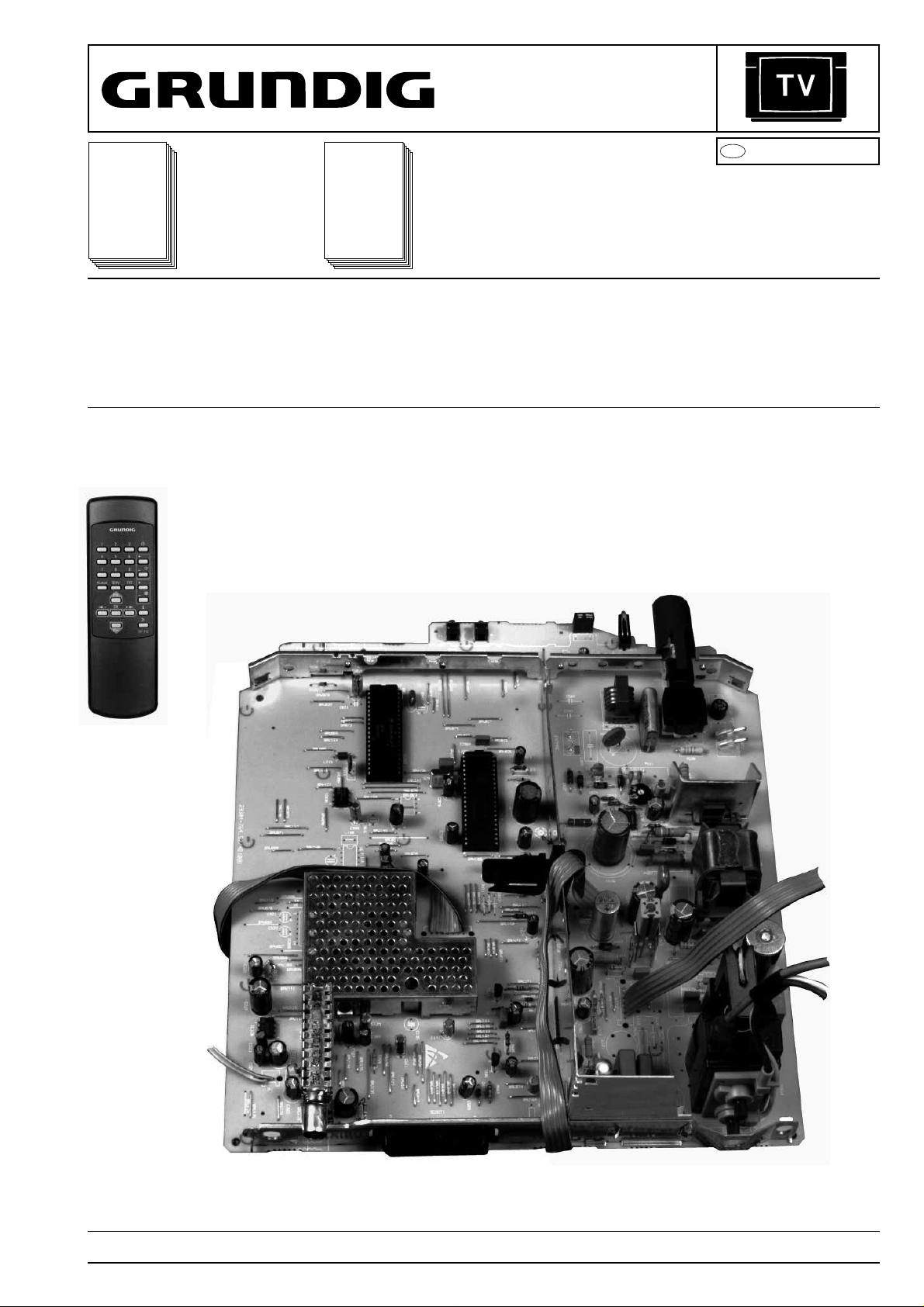
TP 711 (29642-062.01)
Document
supplémentaire
nécessaire pour
la maintenance:
Additionally
required Service
Manuals for the
Complete Service:
Service
Manual
Sicherheit
Safety
Réf. N°./Part No.
72010-800.00
D
Btx * 32700
#
CUC 7301F
P 37 - 843 FR (9.21392-11 / G.CA 7802 FB)
T 51 - 843 FR (9.21477-11 / G.CD 7575 FB)
T 55 - 843 FR (9.21476-11 / G.CC 7675 FB)
Sous réserve de modifications Printed in Germany Service Manual Réf. N°.
Subject to alteration VK 24 1295 Service Manual Part No. 72010-018.50
Page 2

Partie générale / General Section CUC 7301 F
II y a lieu d'observer les recommandations et les
prescriptions de sécurité de I'Instruction de Service "Sécurité" Réf. N° 72010-800.00 ainsi que
les prescriptions spécifiques à chaque pays!
F
Sommaire
Page
Partie générale ....................................1-1... 1-16
Caractéristiques techniques........................................................ .1-3
Composition des appareils........................................................... 1-4
Informations sur la sécurité .......................................................... 1-4
Observaciones sobre los componentes ....................................... 1-4
Indications pour les oscillogrammes ............................................ 1-5
Symboles schéma........................................................................ 1-6
Eléments de commande (P 37-070) .......................................... 1-11
Fonctions de service et fonctions spéciales............................... 1-13
Tableaux des normes et des canaux ........................................ 1-15
Description des circuits ......................2-1... 2-10
1. Le C.I. Alimentation.................................................................. 2-1
2. Le système de commande....................................................... 2-3
3. Le processeur de signal TV TDA 8362 A................................. 2-4
3.1 Généralité........................................................................... 2-4
3.2 Circuit FI............................................................................. 2-4
3.3 Le signal vidéo composite FBAS ....................................... 2-4
3.4 Le signal vidéo composite FBAS externe .......................... 2-5
3.5 Le signal FI audio............................................................... 2-5
3.6 Les signaux de luminance et de chrominance ................... 2-5
3.7 Le signal SECAM et la commutation automatique
PAL-SECAM ...................................................................... 2-6
3.8 Le cheminement du signal RVB ......................................... 2-7
3.9 Génération des signaux de synchro horizontale et verticale ..... 2-7
3.10 L'oscillateur ligne.............................................................. 2-8
3.11 Le circuit de régulation ϕ1 ................................................ 2-8
3.12 Le circuit de régulation ϕ2 ................................................ 2-8
3.13 Le circuit de protection Super Sandcastle........................ 2-8
3.14 Le réglage de courant de Cut-Off..................................... 2-8
3.15 L’étage de puissance horizontale HDR ............................ 2-8
3.16 L’étage de déviation verticale........................................... 2-9
3.17 Compensation de non-entrelacement en télétexte (Option) ... 2-9
3.18 Le circuit de coïncidence.................................................. 2-9
Schéma synoptique................................................................ 2-10
Prescriptions d'alignement ........................... 3-1
C.I. Principal................................................................................. 3-1
Circuits impriméset
schémas électriques.............................4-1... 4-20
Tuner 29504-201.21 .................................................................... 4-1
C.I. Principal................................................................................. 4-3
Schéma synoptique général ........................................................ 4-9
Oscillogrammes ......................................................................... 4-14
Oscillogrammes du C.I. Tube .................................................... 4-16
C.I. Tube 29305-022.14/.15 ...................................................... 4-17
Tuner 29504-201.31 .................................................................. 4-19
The regulations and safety instructions shall be
valid as provided by the "Safety" Service Manual,
part number 72010-800.00, as well as the
respective national deviations.
GB
Table of Contents
Page
General Section ...................................1-1... 1-16
Technical Data ............................................................................. 1-3
Module List................................................................................... 1-4
Safety Advice ............................................................................... 1-4
Hints to the Components ............................................................. 1-4
Hints to the Oscillograms ............................................................. 1-5
Circuit Diagram Symbols ............................................................. 1-6
Service Instructions (P 37-070).................................................. 1-11
Special and Service Functions................................................... 1-13
Tables of Norms and Channels ................................................. 1-15
Descriptions.........................................2-1... 2-10
1. Power Supply ........................................................................... 2-1
2. System Control ........................................................................ 2-3
3. TV Signal Processor TDA 8362 A............................................ 2-4
3.1 Overview ................................................................................ 2-4
3.2 IF ........................................................................................ 2-4
3.3 CCVS-Signal ...................................................................... 2-4
3.4 External CCVS Signal ........................................................ 2-5
3.5 Sound IF............................................................................. 2-5
3.6 Luminance and Chrominance Signal ................................. 2-5
3.7 SECAM Signal Path
and Automatic PAL/SECAM Switching .............................. 2-6
3.8 RGB Signal Path ................................................................ 2-7
3.9 Generation of the Horizontal and Vertical Sync Signals .... 2-7
3.10 Line Oscillator .................................................................. 2-8
3.11 ϕ1-Phase Control ............................................................. 2-8
3.12 ϕ2-Phase Control ............................................................. 2-8
3.13 The Super Sandcastle SSC ............................................. 2-8
3.14 Setting of the Cut-Off Voltage .......................................... 2-8
3.15 The HDR Output Stage .................................................... 2-8
3.16 The Field Deflection Stage............................................... 2-9
3.17 Non-Interlace Compensation with Teletext (optionally).... 2-9
3.18 Coinzidence ..................................................................... 2-9
Block Circuit Diagram............................................................. 2-10
Alignment ....................................................... 3-2
Chassis Board.............................................................................. 3-2
Layout of the PCBs
and Circuit Diagrams.........................4-1... 4-20
Tuner 29504-201.21 .................................................................... 4-1
Chassis Board.............................................................................. 4-3
General Circuit Diagram .............................................................. 4-9
Oscillograms .............................................................................. 4-14
Oscillogrammes CRT Panel....................................................... 4-16
CRT Panel 29305-022.14/.15 .................................................... 4-17
Tuner 29504-201.31 .................................................................. 4-19
Liste de pièces détachées ....................5-1... 5-13
Spare Parts List .................................. 5-1... 5-13
GRUNDIG Service1 - 2
Page 3
CUC 7301 F Partie générale / General Section
Partie générale
Appareils de mesure / Moyens de maintenance
Transfo à tension variable Wobbulomètre
Générateur de mire couleur Oscilloscope à double trace
Multimètre Voltmètre BF
Générateur BF Fréquencemètre
Ces auxiliaires de maintenance peuvent être obtenus auprès des
Stations Techniques Régionales Grundig ou à l'adresse ci-dessous.
Une partie de ces auxiliaires de maintenance est disponible dans le
commerce.
Grundig France
33-35, Boulevard de la Paix
B.P. 204
78104 Saint Germain en Laye
Tel. 30 61 30 00
Telefax 30 61 54 08
Caractéristiques techniques / Technical Data
P 37 - 843 FR T 51 - 843 FR T 55 - 843 FR
Tube image / Picture Tube
Taille de l'image
Visible picture
34cm 48cm 51cm
General Part
Test Equipment / Aids
Variable isolating transformer Test/Sweep Generator
Colour Generator Oscilloscope
DC Voltmeter AF Voltmeter
AF Generator Frequency counter
You can order these test equipments from the Service organization or
at the below mentionned adress. We refer to you that these test
equipments are already obtainable on the market.
Grundig France
33-35, Boulevard de la Paix
B.P. 204
78104 Saint Germain en Laye
Tel. 30 61 30 00
Telefax 30 61 54 08
Taille du tube
Screen diagonale
Angle de déviation
Deflection angle
Fréquence image
Vertical frequency
Electronique / Electronic
Nombre de programmes mémorisables
Programme positions
Commutation péritélévision
AV evaluation
Tuner
Normes de réception
TV standards
Puissance musicale
Music power
Connexions au dos / Connections Rear Panel
Embase Euro AV (noire)
Socket Euro AV (black)
Alimentation / Mains Stage
Tension secteur (Plage de variation)
Mains voltage (variable)
37cm (14")
Tinted glass
79 TV + 1 AV 79 TV + 1 AV 79 TV + 1 AV
Programmable sur chaque position de programme /
PAL, SECAM, BG,
entièrement câblée
fully wired
165 … 265V 165 … 265V 165 … 265V
51cm (20")
Black Matrix
90° 90° 90°
50Hz 50Hz 50Hz
programmable for every programme position
Tuner au pas de 8MHz pour Hyperbande /
cable tuner - 8MHz spacing for hyperband
L/L'
2W 2W 2W
PAL, SECAM, BG,
L/L'
entièrement câblée
fully wired
55cm (21")
Black Matrix
PAL, SECAM, BG,
L/L'
entièrement câblée
fully wired
GRUNDIG Service
Fréquence
Mains frequency
Consommation normale
Power consumption
Consommation en veille
Standby
50 / 60Hz 50 / 60Hz 50 / 60Hz
ca. 40W ca. 55W ca. 60W
ca. 7W ca. 7W ca. 7W
1 - 3
Page 4
Partie générale / General Section CUC 7301 F
Composition des appareils / Module List
Appareil
Unit
P 37 - 843 FR 29701-092.21/.22 29504-201.21/.31 29305-022.14 29642-062.01
T 51 - 843 FR 29701-092.23 29504-201.21/.31 29305-022.15 29642-062.01
T 55 - 843 FR 29701-092.24 29504-201.21/.31 29305-022.15 29642-062.01
Chassis Tuner
Information sur la sécurité
L'émission de rayons X produite par les téléviseurs est conforme aux
spécifications de l'Office Fédéral de Physique et de Technique publiées
le 8 Janvier 1987 (Physikalisch-Technische Bundesanstalt).
La haute tension induite dans le tube et de ce fait l'émission de rayons
X dépend de la précision du réglage de la tension d'alimentation +A.
Après tous travaux de maintenance dans l'alimentation ou dans la
déviation horizontale il y a lieu de contrôler la haute tension et au
besoin de reprendre le réglage.
Les circuits de protection de l'appareil ne doivent être mis hors
service que pendant un temps limité afin d'éviter tous dommages sur
le châssis ou sur le tube.
En cas de remplacement du tube il est recommandé d'utiliser
exclusivement le type de tube spécifié dans la liste de pièces détachées.
C.I. Tube
CRT Panel
Télécommande
Remote Control
Safety Advice
The X-radiation developing in the sets conforms to the X-radiation
Regulations (January 8, 1987), issued by the Physikalisch-Technische Bundesanstalt (federal physiotechnical institution).
The high tension for the picture tube and thus the developing Xradiation depends on the precise adjustment of the +A power
supply.
After every repair of the power supply unit or the horizontal deflection
stage it is imperative that the EHT for the picture tube is checked and
re-adjusted if necessary.
To avoid consequential damages to the chassis or the picture tube
the integrated protective circuits are allowed to be put out of
operation only for a short time.
When replacing the picture tube use only the types specified in the
spare parts lists.
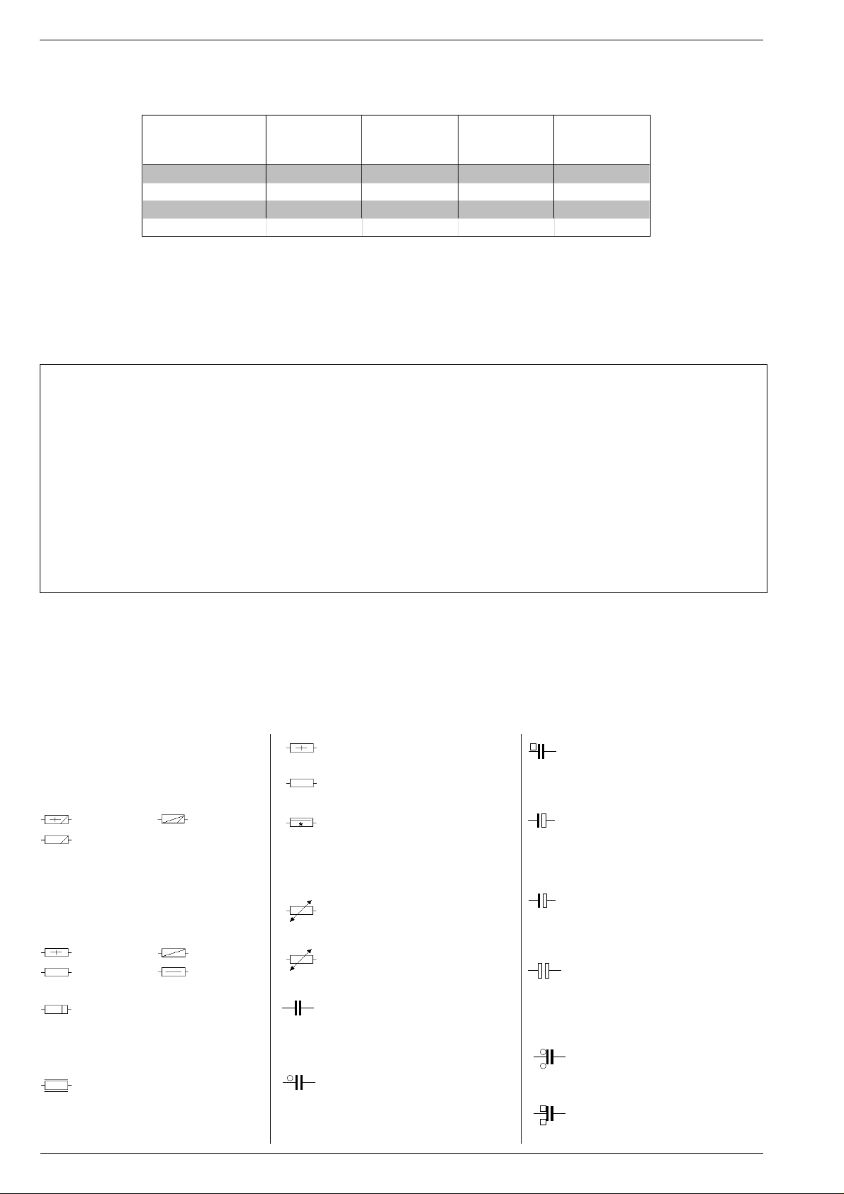
Hinweise zu den Bauteilen / Hints to Components / Istruzioni sui Componenti /
Observaciones sobre los Componentes / Precautions a observer
Metallschichtwiderstände
Metal film resistors
Resistenza a strato metallico
Resistencia de capa metálica
Film métallique
DIN 0204
DIN 0207
Kohleschichtwiderstände
Carbon film resistors
Resistenza a strato di carbone
Resistencia de capa de carbón
Film carbonique
DIN 0204
DIN 0207
Metalloxidwiderstand
Metal oxid resistor
Resistenza ad ossido metallico
Resistencia de óxido metálico
Métaloxide
Schwer entflammbarer Widerstand
Flame resistant resistor
Resistenza anti-infiammabile
Resistencia ininflamable
Ininflammable
DIN 0414
DIN 0414
DIN 0617
Sicherungswiderstand
SI-R
Safety resistor
Resistenza di sicurezza
Resistencia con resorte de seguridad
SI-R
Rés. fusible
Drahtwiderstand m. Wattangabe
Wire wound resistor w. wattage
Resistenza a filo
Resistencia bobinada (Disipación)
Bobinée avec ind. puissance
Heißleiter / NTC resistor
NTC
Termistore NTC / Resistencia CNT
Varistor (CTN)
Kaltleiter / PTC resistor
PTC
Termistore PTC / Resistencia CPT
Varistor (CTP)
Keramikkondensator
K
Ceramic capacitor
Condensatore ceramico
Condensador cerámico
Céramique
Kondensator, Capacitor
Condensatore, Condensador
Condensador, 250 V=
T
Kondensator, Capacitor
Condensatore, Condensador
Condensador, 630 V=
Elektrolytkondensator
Electrolytic capacitor
+
Condensatore elettrolitico
Condensador electrolitico
Electrolytique
Tantal-Elektrolytkondensator
Tantalum electrolytic capacitor
+
Condensatore elettro. al tantalio
Condensador de tantalio
Tantale
bipolarer Elektrolytkondensator
bipolar electrolytic capacitor
Condensatore elettrolitico bipolare
Condensador electrolitico bipolar
Electrolytique bipolaisé
Kondensator, Capacitor
Condensatore, Condensador
Condensador, 400 V=
Kondensator, Capacitor
Condensatore, Condensador
Condensador, 1000 V=
GRUNDIG Service1 - 4
Page 5
CUC 7301 F Partie générale / General Section
Hinweise zu den Oszillogrammen / Hints to the Oscillograms / Note relative agli Oscillogr./
Indications pour les Oscillogrammes / Observaciones con respecto a los Oscilogramas
D
Die Spannungswerte an den Oszillogrammen entsprechen Näherungswerten!
The voltages indicated in the oscillograms
are approximates!
I valori delle tensioni indicati sugli oscillogrammi sono approssimativi !
Les valeurs de tension indiquées sur les
oscillogrammes sont des valeurs approximatives!
Los valores de tensión en los oscilogramas
son aproximados!
GB
. . . V
ss
. . . ms/cm
. . . Hz
. . . V
D
Servicehinweis
Chassisausbau
Bevor Sie die Chassis-Verbindungsleitungen lösen, muß die Leitungsverlegung zu den einzelnen Baugruppen wie Netzschalterplatte, Bedieneinheit, Bildrohrplatte, Ablenkeinheit oder Lautsprecher beachtet
werden.
Nach erfolgter Reparatur ist es notwendig, die Leitungsführung wieder
in den werksseitigen Zustand zu versetzen, um evtl. spätere Ausfälle
oder Störungen zu vermeiden.
Netzkabel
Diese Geräte dürfen nur mit dem Original-Netzanschlußkabel mit
integrierter Entstördrossel betrieben werden. Dieses Netzkabel verhindert Störungen aus dem Netz und ist Bestandteil der Gerätezulassung. Im Ersatzfall bestellen Sie bitte ausschließlich das Netzkabel laut Ersatzteilliste.
GB
Service Note
Disassembly of the chassis
Before disconnecting the chassis connecting leads observe the way
they are routed to the individual assemblies like the mains switch
panel, keyboard control panel, picture tube panel, deflection unit or
loudspeaker.
On completion of the repairs the leads must be laid out as originally
fitted at the factory to avoid later failures or disturbances.
Mains cable
The TV receiver must only be operated with an original mains connecting
cable with an interference suppressor choke integrated in the mains
plug.This mains cable prevents interference from the mains supply and
is part of the product approval. For replacement please order exclusively
the mains connecting cable specified in the spare parts list.
F
Information pour la maintenance
Dèmontage de chassis
Avant de défaire les connecteurs du châssis princip, il y a lieu de
repérer auparavant les liaisons correspondant à chaque platine comme
par exemple le C.I. Inter secteur, le C.I. Commande, le C.I. Tube, le
bloc déviation ou les haut-parleurs.
A la fin de l'intervention, les connexions doivent être remises dans leur
position d'origine afin d'éviter par après d'éventuelles défaillances ou
perturbations.
I
Gleichspannungswert / DC voltage / Valore tensione continua / Tension
continue / Valor de tensión continua
Spitze-Spitze - Wert / Peak to peak value / Valore picco-picco / Crêtecrête / Valor pico a pico
Zeitbasis des Oszilloskops / Time base of the oscilloscope / Base del
tempo dell´oscilloscopio / Base de temps de l´oscilloscope/ Base de
tiempo del oscilocopio
Frequenz / Frequency / Frequenza / Fréquence / Frecuencia
Cable dereseau
Ces appareils ne peuvent être utilisés qu ' avec un cable de connecion
original de réseau avec bobine antiparasite intégré dans la fiche de
secteur. Ce câble de réseau empêche des perturbations de réseau et
est partie de l'autorisation d'appareil. Si nécessaire commandez
uniquement le cable de réseau selon la liste de pièces détachées.
F
E
I
Nota di servizio
Smontaggio del telaio
Prima di sfilare i cavi di collegamneto col telaio è necessario osservare
la disposizione originaria degli stessi verso le singole parti come la
piastra alimentazione, l'unità comandi, la piastra cinescopio, il giogo o
l'altoparlante.
Dopo la riparazione è necessario che gli ancoraggi e le guide
garantiscano la disposizione dei cavi analogamente a quella data in
fabrica e ciò per evitare disturbi o danni nel tempo.
Cavo rete
Gli apperechi devono essere messi in funzioni solo con il cavo originale
il colle gamento di rete e la sua spina di rete deve essere munita di una
bombina d´induttanza. In causa di sostituzione ordinate solo il cavo di
alimentatore che corrésponde alla lista degli accessori.
E
Nota de servicio
Desmontaje del chassis
Antes de desconectar las conecciones del Chassis hay que observar
la dirección de dichas conecciones a los distintos grupos de construcción
como la placa de conmutación de red, unidad de control, placa del
zócalo del tubo de imagen, unidad de deflección o altavoces.
Después de haber realizado la reparación y para evitar fallos o
pertubaciones posteriores es necesario reponer las conecciones tal
como fueron instaladas originalmente en fabrica.
Cable de red
El aparato solo se puede usar con el cable de red original con choque
antiparásito integrado en el enchufe de red. Este cable de red evita
perturbaciones de la red y es parte de la autorización del aparato. En
caso necesario puede pedir el cable de red según lista de piezas de
repuestos.
GRUNDIG Service
1 - 5
Page 6
Partie générale / General Section CUC 7301 F
Schaltplansymbole
D
Simboli sullo schema
I
Netzs.
Netzs.
IR
IR
KH
KH
NTSC
NTSC
FR
FR
OIRT
OIRT
37cm
37cm
FR/OIRT
FR/OIRT
GB
NUR WENN NETZSCHALTER BESTUECKT
ONLY IF MAINS SWITCH IS FITTED
SEUL.SI INTERR.SECTEUR EST MONTE
SOLO QUANDO L'INTERR.DI RETE E' MONTATO
SOLO CUANDO EL INTERR. DE RED ESTA' EQUIPADO
ENTFAELLT WENN NETZSCHALTER BESTUECKT
NOT FITTED IF MAINS SWITCH IS FITTED
N' EXISTE PAS SI INTERR.SECTEUR EST MONTE
MANCA QUANDO L'INTERR.DI RETE E' MONTATO
NO EXISTE CUANDO EL INTERR.DE RED ESTA' EQUIPADO
NUR WENN IR- EMPFAENGER BESTUECKT
ONLY IF IR RECEIVER IS FITTED
SEUL.SI RECEPTEUR IR EST MONTE
SOLO QUANDO IL RICEVITORE IR E' MONTATO
SOLO CUANDO EL RECEPTOR IR ESTA EQUIPADO
ENTFAELLT WENN IR-EMPFAENGER BESTUECKT
NOT FITTED IF IR RECEIVER IS FITTED
N'EXISTE PAS SI REC.IR EST MONTE
MANCA QUANDO L'INTERR.DI RETE E' MONTATO
NO EXISTE CUANDO EL RECEPTOR IR ESTA EQUIPADO
NUR WENN KH-BUCHSE BESTUECKT
ONLY WITH HEADPHONE SOCKET IS FITTED
SEUL.SI DOUILLE ECOUTEUR EST MONTE
SOLO QUANDO E' MONTATA LA PRESA CUFFIA
SOLO CUANDO EL ENCHUFE DE AURIC.ESTA EQUIPADO
ENTFAELLT WENN KH-BUCHSE BESTUECKT
NOT FITTED IF HEADPHONE SOCKET IS FITTED
N'EXISTE PAS SI DOUILLE EC.EST MONTE
MANCA QUANDO E' MONTATA LA PRESA CUFFIA
NO EXISTE CUANDO EL ENCHUFE DE AURIC.ESTA EQUIPADO
NUR BEI NTSC
ONLY WITH NTSC
SEUL.POUR NTSC
SOLO CON NTSC
SOLO CON NTSC
ENTFAELLT BEI NTSC
NOT FITTED ON NTSC
N'EXISTE PAS POUR NTSC
MANCA NELLA VERS. NTSC
NO EXISTE CON NTSC
NUR BEI FR
ONLY WITH FR
SEUL.POUR FR
SOLO NELLA VERS.FR
SOLO CON FR
ENTFAELLT BEI FR
NOT FITTED ON FR
N'EXISTE PAS POUR FR
MANCA NELLA VERS.FR
NO EXISTE EN FR
NUR BEI OITR
ONLY WITH OIRT
SEUL.POUR OIRT
SOLO NELLA VERS.OIRT
SOLO CON OIRT
ENTFAELLT BEI OIRT
NOT FITTED ON OIRT
N'EXISTE PAS POUR OIRT
MANCA NELLA VERS.OIRT
NO EXISTE EN OIRT
NUR BEI OIRT
ONLY WITH OIRT
SEUL.POUR OIRT
SOLO NELLA VERS.OIRT
SOLO CON OIRT
ENTFAELLT BEI OIRT
NOT FITTED ON OIRT
N'EXISTE PAS POUR OIRT
MANCA NELLA VERS.OIRT
NO EXISTE EN OIRT
NUR BEI FR/OIRT
ONLY WITH FR/OIRT
SEUL.POUR FR/OIRT
SOLO NELLA VERS.FR/OIRT
SOLO CON FR/OIRT
ENTFAELLT BEI FR/OIRT
NOT FITTED ON FR/OIRT
N'EXISTE PAS POUR FR/OIRT
MANCA NELLA VERS.FR/OIRT
NO EXISTE EN FR/OIRT
NUR BEI GB
ONLY WITH GB
SEUL.POUR GB
SOLO NELLA VERS.GB
SOLO CON GB
Circuit Diagram Symbols
GB
E
Simbolos en los esquemas
GB
TEXT
TEXT
n.V.
S-VHS
S-VHS
INL
INL
MULTI
MULTI
--> Netzs
--> BED
--> BED/NS
--> BR
--> Abst.
--> Chass
Symboles schéma
F
ENTFAELLT BEI GB
NOT FITTED ON GB
N'EXISTE PAS POUR GB
MANCA NELLA VERS.GB
NO EXISTE EN GB
NUR BEI TEXT
NOT FITTED ON TELETEXTE
SEUL.POUR TELETEXTE
SOLO NELLA VERS.TELEVIDEO
SOLAM.CON TELETEXTO
ENTFAELLT BEI TEXT
NOT FITED ON TELETEXT
N'EXISTE PAS POUR TELETEXTE
MANCA NELLA VERS.TELEVIDEO
NO EXISTE EN TELETEXTO
NUR VORGESEHEN
ONLY PROVIDED FOR
PREVU
SOLO PREVISTO
SOLAM.PREVISTO
NUR BEI S-VHS
ONLY WITH S-VHS
SEUL.POUR S-VHS
SOLO NELLA VERS.S-VHS
SOLAM.CON S-VHS
ENTFAELLT BEI S-VHS
NOT FITTED ON S-VHS
N'EXISTE PAS POUR S-VHS
MANCA NELLA VERS.S-VHS
NO EXISTE EN S-VHS
NUR BEI PAL BG
ONLY WITH PAL BG
SEUL.POUR PAL BG
SOLO NELLA VERS.PAL BG
SOLAM.CON PAL BG
ENTFAELLT BEI PAL BG
NOT FITTED ON PAL BG
N'EXISTE PAS POUR PAL BG
MANCA NELLA VERS.PAL BG
NO EXISTE EN PAL BG
NUR BEI MULTI
ONLY WITH MULTI
SEUL.POUR MULTI
SOLO NELLA VERS.MULTI
SOLO CON MULTI
ENTFAELLT BEI MULTI
NOT FITTED ON MULTI
N'EXISTE PAS POUR MULTI
MANCA NELLA VERS.MULTI
NO EXISTE EN MULTI
ZUR NETZSCHALTERPL.
TO MAINS SWITCH BOARD
VERS C.I.INTERR.SECTEUR
ALLA PIASTRA INTERR.DI RETE
A LA PLACA INTERRUPTOR DE RED
ZUR BED.EINHEIT
TO CONTROL UNIT
VERS L'UNITE DE COMANDE
ALL'UNITA DI COMANDO
A LA UNIDAD DE MANDO
ZUR BED.-EINHEIT ODER NETZSCHALTERPLATTE
TO CONTROL UNIT / MAINS SWITCH PANEL
VERS L'UNITE DE COMANDE/C.I.INTERR. SECTEUR
ALL' UNITA DI COMANDO / PIASTRA INTERR.DI RETE
A LA UNIDAD DE MANDO / PLACA INTERR.DE RED
ZUR BILDROHRPLATTE
TO CRT BASE
VERS C.I. TUBE CATHODIQUE
ALLA PIASTRA CINESCOPIO
A LA PLACA-ZOCALO TRC
ZUM ABSTIMM-BAUSTEIN
TO TUNING MODULE
VERS MOD.DE SYNTH.
AL MOD.DI SINTONIA
AL MOD.DE SINTONIA
ZUM CHASSIS
TO CHASSIS
VERS CHASSIS
AL TELAIO
AL CHASIS
GRUNDIG Service1 - 6
Page 7
CUC 7301 F Partie générale / General Section
FBAS
MAC
FBAS
TXT
+
-
REF.
ABK
AUDIO
AUDIO-L
AUDIO-R
AUDIO
MAC
AUDIO
L - MAC
AUDIO
R - MAC
AUDIO
TV
AUDIO
VCR
B
BB
BB
B
EXT
B
PIP
B/50
B/100
B-Y
50
B-Y
100
C
CENTER
Feinabst. + / Fine tuning + / Réglage fine + / Sint. fine + / Sint. fina +
Feinabst. - / Fine tuning - / Réglage fine - / Sint. fine - / Sint. fina Lautstärke / Volume / Volume / Volume sonore / Volumen
Referenz Lautstärke / Volume ref. volt. / Tens. de réf. vol. sonore /
Tens di rif. volume / Tens. ref. volumen
Balance / Balance / Balance /Balanciam. / Balance
Suchlauf / Self seek / Recherche autom. / Sint. autom. / Sintonia
automatica
Farbton / Tint / Teinte / Tinta / Tinte
Helligkeit / Brightness / Luminosité / Luminosita / Brillo
Kontrast / Contrast / Contraste / Contrasto / Contraste
Farbkontrast / Colour contrast / Contraste des coleurs / Contrasto
colore / Contraste de color
Schutzschaltung / Protection circuit / Circuit de sécurité / Circuito di
protezione / Circuito de protección
(Burst Key): Burstaustastimpuls / Burst blanking pulse / Impulsion de
suppress. de burst / Imp. di soppress. del burst / Imp. supresion burst
Ton-Signal / Audio signal / Signal audio / segnale audio / Señal audio
Ton-Signal links / Audio signal left / Signal audio gauche / Segnale
audio sinistra / Señal audio izquierda
Ton-Signal rechts / Audio signal right / Signal audio droit / Segnale
audio destra / Señal audio derecha
Tonsignal D2 Mac / Audio signal D2MAC / Signal audio D2MAC /
Segnale audio D2MAC / Señal de sonido D2MAC /
Tonsignal links D2 Mac / Audio signal left D2MAC / Signal audio
gauche D2MAC / Segnale audio sinistro D2MAC / Señal de sonido
izquirdo D2MAC /
Tonsignal rechts D2 MAC / Audio signal right D2MAC / Signal audio
droit D2MAC / Segnale audio destro D2MAC / Señal de sonido
derecho D2MAC /
Audio-Signal FS Gerät / Audio signal TV set / Signal audio
téléviseur / Segnale audio TV / Señal audio TV
Tonsignal VCR Gerät / Audio signal VCR unit / Signal audio
magnetoscope / Segnale audio VCR / Señal audio VCR
Blau-Signal / Blue signal / Signal bleu / Segnale blu / Señal azul
Rechner Stop I2C Bus frei / Computer Stop I2C Bus is free /
Microprocesseur stop I2C Bus disponible / Calcol. stop I2C Bus
libero / Stop micropr. disponible
Basisband / Baseband / Bande de base / Banda base / Banda base
Blau-Signal extern / Signal blue external /Signal bleu externe /
Segnale blu esterno / Señal azul externa
Blau-Signal PIP / PIP Blue signal / Signal bleu PIP / Segnale blu
PIP / Señal azul PIP
Blau - Signal - 50Hz vert.,15625Hz hor. / Blue signal - 50Hz vert.,
15625Hz hor. / Signal bleu - 50Hz vert., 15625Hz hor. / Segnale bleu
- 50Hz vert., 15625Hz hor. / Señal azul - 50Hz vert., 15625Hz hor.
Blau-Signal -100Hz vert., 31250Hz hor. / Blue signal -100Hz vert.,
31250Hz hor. / Signal bleu -100Hz vert., 31250Hz hor. / Segnale blu
-100Hz vert., 31250Hz hor. / Señal azul -100Hz vert., 31250Hz hor.
B-Y -Signal - 50Hz vert., 15625Hz hor. / B-Y -Signal - 50Hz vert.,
15625Hz hor. / Signal B-Y - 50Hz vert., 15625Hz hor. / Segnale BY - 50Hz vert., 15625Hz hor. / Señal B-Y - 50Hz vert., 15625Hz hor.
B-Y -Signal - 100Hz vert., 31250Hz hor. / B-Y -Signal - 100Hz vert.,
31250Hz hor. / Signal B-Y - 100Hz vert., 31250Hz hor. / Segnale BY - 100Hz vert., 31250Hz hor. / Señal B-Y - 100Hz vert., 31250Hz hor.
Kanalwahl / Channel selection / Sélection de canaux / Selez.
canale / Seleccion canal
Mitttelpunkt-Lautsprecher / Center loudspeaker / Haut-parleur de
centre / Alto parlante punto centrale / Altavoz del centro
CHIP
AD
CINCH
AUDIO L
CINCH
AUDIO R
CHROMA
S-VHS
CLK
CL 1
CL 2
CSY
CS
100
DATA
DL
ENA
ZF
ENABLE
FT
ENABLE
LED
ENABLE
TON
EURO-AV
AUDIO-L
EURO-AV
AUDIO-R
EURO-AV
VIDEO
F
FBAS
FBAS
TON
FBAS
SYNC.
FBAS
S-VHS
F
H
FRM
FT
F
U
Chip Adresse / Chip adress / Chip direction / Indiri. del chip /
Direccion chip
Ton-Signal Cinch links / Audio signal cinch left / Signal audio cinch
gauche / Segnale audio cinch sinistra / Señal audio cinch izquierda
Ton-Signal Cinch rechts / Audio signal cinch right / Signal audio
cinch droit / Segnale audio cinch destra / Señal audio cinch derecha
Chroma S-VHS-Signal / Chroma S-VHS-Signal / Signal dégree de
S-VHS / Croma segnale S-VHS / Señal croma S-VHS
Clock
Composite Sync. Imp. für VT / Composite sync pulse for TT / Imp. de
sync. vidéo-composite pour TXT / Imp. hor. para Video Comp.
Kombiniertes Hor./vert. Sync. Signal 31250Hz/100Hz (Composite
Sync.) / Combined hor./vert. sync signal 31250Hz/100Hz (Composite Sync) / Signal synchr. hor./vert. combiné 31250Hz/100Hz
(Synchr. composité) / Segnale sincr. orizz./vert. 31250Hz/100Hz
(Sincr. Composito) / Señal combinada sincr. hor./vert. 31250/100Hz
(Sincr. compuesto)
Daten / Data / Données / Dati / Datos
Verzögerungsleitung / Delay line / Ligne à retard / Linea di ritardo /
Linea de retardo
Freigabe ZF / IF Enable / Validation FI / Consenso FI / Autorizacón FI
Freigabe FT / Finetuning enable / Autorisation Réglage fin / Abilitaz.
Sintonia fine / Habilitacion Sintoinia fina
Freigabe LED / LED enable / Autorisation LED / Abilitaz. LED /
Habilitacion LED
Freigabe Ton / Sound enable / Autorisation son / Abilitaz. audio /
Habilitacion sonido
Audio-Signal EURO-AV links / Audio signal EURO-AV left / Signal
audio EURO-AV gauche / Segnale audio EURO-AV sinistra / Señal
audio izquierda EURO-AV
Audio-Signal EURO-AV rechts / Signal audio EURO-AV right /
Signal audio EURO-AV droit / Segnale audio EURO-AV destra /
Señal audio derecha EURO-AV
Video-Signal EURO-AV / Video signal EURO-AV / Signal video
EURO-AV / Segnale video EURO-AV / Señal video EURO-AV
Farb-Signal / Chroma signal / Signal chroma / Segnale chroma /
Señal croma
FBAS-Signal / CCVS signal / Signal vidéo composite / Segnale video
composito / señal video compuesta
FBAS-D2 MAC / D2MAC CCVS signal / Signal vidéo compositeD2MAC / FBAS-D2MAC / FBAS-D2MAC
Basisband / Baseband / Bande de base / Banda base / Banda base
FBAS-Videotext / CCVS videotext / Signal vidéo compositeTélétexte / FBAS-Televideo / FBAS-Teletexto
FBAS Sync. Signal / CCVS sync signal / Signal sync. vidéo col.
comp. / Segnal sincr. video col. comp. / Señal sincr. video
compuesta
FBAS Signal S-VHS / CCVS signal S-VHS / Signal vidéo col. comp.
S-VHS / Segnal video col. comp. S-VHS / Señal video compuesta
S-VHS
Hochspg. / EHT voltage / Haute tens. / Alta tens. / MAT
Rahmensignal / Frame signal / Signal d'encadrement / Segnale
cornice / Señal de marco
Feinabstimmung / Fine tuning / Reglage fin / Sint. fine / Sint. fina
FU-Signal / FU-signal / Signal FU / Segnale FU / Senal FU
GRUNDIG Service
1 - 7
Page 8

Partie générale / General Section CUC 7301 F
F
FV-Signal / FV-signal / Signal FV / Segnale FV / Senal FV
V
G
G
PIP
G
EXT
G/50
G/100
GND - H
HA
HDR
HC
HFB
HS
I
BEAM
ICL
IR
IM
CLOCK
Grün-Signal / Green signal / Signal green external / Signal vert /
Segnale verde / Señal verde
Grün-Signal PIP / Green signal PIP / Signal green PIP/ Signal vert
PIP / Segnale verde PIP / Señal verde PIP
Grün-Signal extern / Green signal vertical / Signal vert externe /
Segnale verde esterno / Señal verde externa
Grün-Signal - 50Hz vert.,15625Hz hor. / Green signal - 50Hz vert.,
15625Hz hor. / Signal vert - 50Hz vert., 15625Hz hor. / Segnale
verde - 50Hz vert., 15625Hz hor. / Señal verde -50Hz vert., 15625Hz
hor.
Grün-Signal -100Hz vert., 31250Hz hor. / Green signal -100Hz vert.,
31250Hz hor. / Signal vert -100Hz vert., 31250Hz hor. / Segnale
verde -100Hz vert., 31250Hz hor. / Señal verde -100Hz vert.,
31250Hz hor.
Nullpunkt Heizung / Ground filament / Point neutre-Chauffage /
Punto zero-Filamento / Punto medio filamento
Horiz. Sync. Impuls / Horiz. Sync pulse / Impulsion synchro. horiz. /
Impulso sincro orizzontale / Impulso de sinc. horiz.
Horiz. Ansteuerimpuls / Horiz. drive pulse / Impulsion de commande
horiz. / Impulso comando orizzontale / Impulso de control horiz.
Horiz. Klemmimpuls / Horiz. clamp pulse / Impulsion de serrage
horiz. / Impulso comando orizzontale / Impulso de garras horiz.
Horiz. Rückschlagimpuls / Horiz. flyback / Impulsion de retour
horiz. / Impulso rotorno orizzontale / Impulso de retroceso horiz.
Hor. Sync. Implus für VT / Hor. sync pulse for TT / Imp. de sync. hor.
pour TXT / Imp. sincr. orizz. per Televideo / Imp. hor. para Video
Comp.
Strahlstrom / Current beam / Current rayon / Corrante del irradire /
Corriente de haz
I2C Bus -Clock
Infrarot-Signal / Signal infrared / Signal infra-rouge / Segnale
infrarosso / Señal infrarojo.
I2C Bus -Clock
REMOTE
R
R-Y
R-Y
SCL
SCL 100
SDA
SHIFT
VIDEO
Programm / Program / Programme / Programma /Programa
P
Programm-Kanalwahl / Program channel selection / Progr. sélection
P/C
de canaux / Progr. selez.canale / Progr. selec. canal
Bild im Bild / Picture in picture / Image dans l'image / PIP / Imagen
PIP
en la imagen
Progr. Taste / Progr. button / Touche Progr. / Tasto Progr. / Puls.
P1
Progr.
Rot-Signal / Red signal / Signal rouge / Segnale rosso / Señal roja
R
Fernbedienung / Remote control / Telecommande / Telecomando /
Mando a distancia
Rot-Signal PIP / Red signal PIP / Signal rouge PIP / Segnale rosso
PIP
PIP / Señal roja PIP
Rot-Signal extern / Signal red external / Signal rouge externe /
R
EXT
Segnale rosso esterno / Señal rojo externa
R-Y -Signal - 50Hz vert., 15625Hz hor. / R-Y -Signal - 50Hz vert.,
50
15625Hz hor. / Signal R-Y - 50Hz vert., 15625Hz hor. / Segnale RY - 50Hz vert., 15625Hz hor. / Señal R-Y - 50Hz vert., 15625Hz hor.
R-Y -Signal - 100Hz vert., 31250Hz hor. / R-Y -Signal - 100Hz vert.,
100
31250Hz hor. / Signal R-Y - 100Hz vert., 31250Hz hor. / Segnale
R-Y - 100Hz vert., 31250Hz hor. / Señal R-Y - 100Hz vert., 31250Hz
hor.
Sonderkanal / Special channel / Canal special / Canale speciale /
S
Canal especial
Strahlstrombegrenzung / Beam current lim. / Lim. cour. de faisceau /
SB
Lim. corr. di raggio / Corriente media de haz
I2C-Bus Clock
Schneller I2C-Bus Clock / I2C-Bus clock high speed / I2C-Bus grande
vitesse / I2C-Bus veloce / Clock del I2C-Bus de alta velocida
I2C-Bus Daten / I2C-Bus data / I2C-Bus données / I2C-Bus dati /
I2C-Bus datos
Dynamische vert. Versch. 25Hz, aktiv bei Video u. Mix Betrieb /
Dynam. vert. shift 25Hz, active on video and mix operation / Decal
dynam. de l'image 25Hz, actif sur video et fonction. mixte / Spostam.
vert. dinam. 25Hz, attivo con video e. funzionam. misto / Desplaz.
dinamico vert. 25Hz, activo con video Y funciones mixtas
IM
IDENT
I2C Bus -Kennung / I2C-Bus Identification / Identification I2C-Bus /
Ident. I2C-Bus, Identification I2C-Bus
SHIFT
TEXT
Dynamische vert. Versch. 25Hz, aktiv bei Standbild u. VT / Dyn. vert.
shift 25Hz, active on freeze-frame and Teletext / Decal dynam. de
l'image 25Hz, actif sur arret immage et Vidéotext (Antiope) /
IM
RESET
I2C Bus -Reset
Spostam. vert. dinam. 25Hz, attivo con fermo immag. e Televideo /
Desplaz. dinamico vert. 25Hz, activo con imagen parada Y
Videotexto
IR CLK
IR DATA
VIDEO
AUDIO-L
LED
AUDIO-R
NIC CLK
NORM
OWA
Infrarot Clock / Infrared clock / Signal I.R. horloge / Clock segnale
R.I. / Clock infrarojos
Infrarot Signal / Infrared signal / Signal I.R. / Segnale infrarosso /
Data infrarrojos
IR
Infrarot Signal Video / Infrared signal video / Signal I.R. video /
Segnale infrarosso video / Data infrarrojos video
Tonsignal Kopfhörer links / Audio signal headphone left / Signal
KH
audio gauche de casque / Segnale audio sinistra cuffia / Señal audio
izquierda auriculares
Lautstärke / Volume / Volume / Volume sonore / Volumen
L
Leuchtdiode / Light emitting diode / Diode lumineuse / Diodo
luminoso / Diodo luminescente
Tonsignal Kopfhörer rechts / Audio signal headphone right / Signal
KH
audio droit de casque / Segnale audio sinistra cuffia / Señal audio
derecha auriculares
Speicher Taste / Memory button / Touche mémoire / Tasto di
M
memoria / Puls. memoria
NICAM Clock / Clock NICAM / Horloge NICAM / Clock NICAM /
Clock NICAM
Norm Taste / TV standard select button / touche de norme / Tasto
norma / Puls. de norma
Ost-West Ansteuerimpuls / East-west drive impuls / Impulsion de
commande Est-Ouest / Impulso comando Est-Ovest / Impulso de
SS
SSB
SSC
SSC
PIP
SSC
SSC
SUR-
ROUND
SYNC
SYNC.
BTX
SYNC.
SW
TE
Schutzschaltung / Protection circuit / Cablage protecteur / Pot. de
prot. / Circuito de proteccion
Spitzenstrahlstrombegrenzung / Peak beam current limiting / Lim.
de faisceau crete / Lim. corr. catod. di pico / Corrente pico de haz
Supersandcastle
Supersandcastle PIP
Supersandcastle 100Hz vert., 31250Hz hor.
100
Supersandcastle 50Hz vert., 15625Hz hor.
50
Surround
Sync.-Signal / Sync.-Signal / Signal sync / Segnale sync. / Señal de
sync.
Sync. BTX / Viewdata Sync / Sync. Télétext / Sincr. Videotel / Sincr.
Videotexto
Sync. VT / Sync. Teletext / Sync Vidéotexte / Sincr. Televideo / Sincr.
VT
Videotexto
Schwarzwert / Black level / Niveau du noir / Livello del nero / Nivel
de negro
TEXT-Freigabe / TEXT enable / Autorisation TEXTE / Abilitaz.
TELEVIDEO / Habilatation TEXTE
control Este-Oeste
GRUNDIG Service1 - 8
Page 9

CUC 7301 F Partie générale / General Section
T1
T2
T T
U
FOC
U
U
U
SG
U
G 2
VA
VB
VCL
VDR
VG
VIDEO
VT DATA
VT SCL
VT SDA
Y
Y
Y
ZF
AFC
U
U
AV
U
BA
U
BTX
U
C-AV
U
CAM
AV
U
DATA
U
U DAT A
EXT
Bei Zweiton, Ton 1 / On two channel sound, sound 1 / Pour double
son, son 1 / In bicanale, audio 1 / En dual, sonido 1
Bei Zweiton, Ton 2 / On two channel sound, sound 2 / Pour double
son, son 2 / In bicanale, audio 2 / En dual, sonido 2
Tieftöner / Woofer / Haut-parleur pour les frequences basses / Toni
bassi / Sonido bajo
Fokusspg. / Focussing volt. / Tens. de focalis. / Tens di focalizz. /
Tens focalizacion
Spg. Gitter 1 / Volt. grid 1 / Tens grille G 1 / Tens. griglia 1 / Tens.
G1
rejillas G 1
H
Hochspannung / High voltage / Haute tension / EAT / Alte tension
Schirmgitter Spg. / Screen-grid volt. / Tens. de grille - écran / Tens.di
griglia schermo / Tens. de rejilla
Vertikaler Ansteuerimpuls / Vert. drive pulse / Impulsion de
commande verticale / Impulso di comando verticale / Impulso de
control vertical
VCR - Clock
Freigabe Anzeigebaustein / Display enable / Autorisation pour
module indicateur / Modulo indicazione / Habilitacion modulo
indicacion
Vert. Gegenkopplung / Vert. feedback / Contre-reaction verticale /
Controreazione vert. / Aliment. neg. vert.
Video Signal / Video signal / Signal vidéo / Segnale video / Señal
video
VT Daten / Teletext data / Données Teletexte / Linea dati Televideo /
Data Teletexto
Videotext Clock / Teletext clock / Signal horloge Vidéotext / Clock
Televideo / Clock Teletexto
I2C Bus: VT Daten / Teletext data / Données Vidéotext / Dati
Televideo / Data Teletexto
Y-Signal / Y Signal / Signal Y /Segnale Y / Señal Y
Y -Signal - 50Hz vert., 15625Hz hor. / Y -Signal - 50Hz vert.,
50
15625Hz hor. / Signal Y - 50Hz vert., 15625Hz hor. / Segnale
Y - 50Hz vert., 15625Hz hor. / Señal Y - 50Hz vert., 15625Hz hor.
Y - Signal - 100Hz vert., 31250Hz hor. / Y -Signal - 100Hz vert.,
100
31250Hz hor. / Signal Y - 100Hz vert., 31250Hz hor. / Segnale
Y - 100Hz vert., 31250Hz hor. / Señal Y - 100Hz vert., 31250Hz hor
Zwischenfrequenz / IF / FI / FI / FI
Schaltspg. AFC / AFC switching volt. / Tens. de commut. AFC/ Tens.
di commut. AFC / Tens. conmut. CAF
Schaltspg. AV / Switching volt. AV / Tens. de commut. AV / Tens. di
commut. AV / Tens. conmut. AV
Schaltspg. Bildamplitude / Switching voltage vertical amplitude /
Tension de coupure amplitude dìmage / Tensione di commutaz.
ampiezza d'imagine / Tension de conm. amplitude de imagen di
commut. PAL / Tens. conmut. PAL
Schaltspg. BTX / Switching volt. BTX (Viewdata) / Tens. commut.
Télétext / Tens. commut. VIDEOTEL / Tens. conmut. Teletexto
Schaltspg. Camera Wiederg. über C-AV Eingang/ Switching volt.
cam. playback via C-AV input / Tens de commut pour lec. de camera
par l'entree C-AV / Tens.de commut. in riproduz. cam tramite
ingresso C-AV / Tens. de serv. reprod. camera a traves de la entrada
C-AV
Schaltspg. Camera Wiedergabe / Switching volt. camera playback /
Tens. commut. reprod. camera / Tens. commut. riproduz. telecam /
Tens. conm. reprod. camara
Schaltspg. Datenbetr. / Switching volt. data mode / Tens. de commut. fonct. données / Tens. di commut. dati / Tens conmut. datos
Schaltspg. U Data extern / Switching volt Data ext. / Tension de
commutation U Data externe / Tens. di commutazione U-Data
esterno / Tensión de conmutatón externa U
U
DEEM
U
DS
U
MAC
U
EURO-
U
EU-AV
CINCH
U
FBAS
U
HIFI
U
HI FI
MUTE
U
HUB
U
KH
MUTE
U KOIN
50/60Hz
KOIN
U
VQ
U
LED
U
Leucht-.
punkt
U
LNC
OFF
U
MUTE
U
NF 1
U
NF 2
U
NIC
U
NORM
U
PAL
U
POL.
U
RESET
U
SCHUTZ
U
SEC
STAND
U
BY
U
S-VHS
Schaltspg. Deemphasis / Switching volt. deemphasis / Tens. commut. desaccent. / Tens. commut. deenfasi / Tens. conmut. deenfasis
Schaltspg. Dolby-Surround / Switching volt. Dolby-Surround / Tens.
commut. Dolby-Surround / Tens. commut. di Dolby-Surround / Tens.
de conmut. Dolby-Surround
Schaltspg. D2MAC / Switching volt. D2MAC / Tension de
commutation D2MAC / Tens. di commtazione D2MAC / Tensión de
conmutación D2MAC
Schaltspg. EURO-AV / Switching volt. EURO-AV / Tens. de commut.
AV
EURO-AV / Tens. di commut. EURO-AV / Tens. conmut. EURO-AV
Schaltspg. EURO-AV-Cinch-Buchse / Switching volt. EURO-AV-
Cinch socket / Tens. commut. prisa Scart - Cinch / Tens. commut.
presa Scart -Cinch / Tens. conm. EURO-AV - Cinch
Schaltspannung für Video-Ausgang EURO-AV Buchse / Switch.
voltage for video output EURO-AV socket / Tension de commut.
pour sortie vidéo EURO-AV / Tension commut. per presa d'uscita
video EURO-AV / Tension de conmut. para salida EURO-AV
Schaltspg. HIFI / Switching voltage HIFI / Tens. de commut. HIFI /
Tens di commut. HIFI / Tens. conmut. HIFI
Stummschaltung HiFi / Muting volt. HiFi / Commutation de silence
HiFi / Silenzametno HiFi / Muting HiFi
Schaltspg. HUB / Switching volt. deviation / Tens. commut.
déviation / Tens. commut. deviazione / Tens. conmut. deviacion
Stummschaltung Kopfhörer / Muting volt. headphone / Commutation
de silence casque / Silenzamento cuffia / Muting auriculares
Schaltspg. Koinz. / Switching volt. coinc. / Tens de commut. coinc. /
Tens di commut. coinc. / Tens. conmut. coinc.
Schaltspg. Koinz. mit Videoquelle verknüpft / Coinc. switching volt.
linked with video source / Signal de coincid. combiné avec source
video / Tens. di commut. a coinc. combinata con sorg video senal
de coincidencia combinada con video
Schaltspg. LED / Switching volt. LED / Tens de commut. LED /
Commut. di commut. LED / Conmut. LED
Schaltspg. Leuchtpunktunterdrückung / Switching volt. beam spot
suppression / Tens. de commut. suppress. du spot lumineux / Tens.
soppr. punto luminoso / Tens. de conmut. filtro supresor del punto luz
Schaltspg. LNC "Aus" / Switching volt. LNC "OFF" / Tens. de
commut. LNC "OFF" / Tensione di commut. "Spento" LNC / Tension
LNC "OFF"
Stummschaltung / Muting / Silencieux / Silenziamento /Muting
Schaltspg. NF 1 / Switching volt. AF 1 / Tension commut. BF 1 / Tens.
commut BF 1 / Tens. conm. BF 1
Schaltspg. NF 2 / Switching volt. AF 2 / Tension commut. BF 2 / Tens.
commut BF 2 / Tens. conm. BF 2
Schaltspg. NICAM / Switching volt. NICAM / Tens. de commut.
NICAM / Tens. commut. NICAM / Tens. de conmut. NICAM
Schaltspg. Norm / Switching volt. Norm / Tens. de commut.
standard / Tens. di commut. Norma / Tens. conmut. Norma
Schaltspg. PAL / Switching volt. PAL / Tens. de commut. PAL / Tens
Schaltspg. Polarität / Switching volt. polarity / Tension commut.
polarite / Tens. commut. polarita / Tens. conmut polarizacion
Schaltspg. Reset / Switching volt. Reset / Tens. commut. Reset /
Tens. commut. Reset / Tens. conmut. Reset
Schaltspg.-Schutzfunktion / Switching volt.-protective func. / Tens
de commut.-sécurité / Tens. di commut.-funz di protez. / Tens.
conmut.-proteccion
Schaltspg. SECAM / Switching volt. SECAM / Tens. de commut.
SECAM / Tens. di commut. SECAM / Tens. conm. SECAM
Schaltspg. Standby / Switching volt. Standby / Tens. commut.
Veille / Tens. commut. Standby / Tens. conmut. Standby
Schaltspg. S-VHS / Switching volt. S-VHS / Tens.de commut.
S-VHS / Tens. de commut. S-VHS / Tens. de conmut. S-VHS
GRUNDIG Service
1 - 9
Page 10
Partie générale / General Section CUC 7301 F
U TON
1/2
U
UHF
U
VHF
U
VQ
U
WISCH
U
W/N
U
I / III
U
14V
U
22kHz
0/3/6/9V
U
4.5MHz
U
50/60
HZ
U
AFC
SAT
U
AGC
U
RE
Schaltspg. Ton 1-2 / Switching volt. sound 1-2 / Tens. commut. audio
1-2 / Tens. commut. son 1-2 / Tens. conmut. son 1-2
Schaltspg. UHF / UHF switching volt. / Tens. de commut. UHF / Tens
di commut. UHF / Tens. conmut. UHF
Schaltspg. VHF / VHF switching volt. / Tens. de commut. VHF / Tens
di commut. VHF / Tens. conmut. VHF
Schaltspg. Videoquelle / Switching volt. video source / Tens. de
commut. source video / Tens. di commut. sorg. video / Tens conmut.
video
Schaltspg. Wischerkontakt / Schwitching voltage temp. contact /
Tens. de commut. contact fugitif / Tens. commut. contatto / Contacto
supresor tens. de conmut.
Schaltspg. ZF breit - schmal / IF switching volt. wide - narrow / Tens.
commut. FI large - etroit / Tens. commut. FI larga - stretta / Tens. FI
ancho - estrecho
Schaltspg. Bandwahl / Band sel. switching volt. / Tens. de commut.
select. bande / Tens. di commut. selez. banda / Tens. conmut. selec.
banda
14V Schaltspg. / 14V switching volt. / Tens. commut. 14V / Tens.
commut. 14V / Tens. de conm. 14V
22kHz Schaltspg. / 22kHz switching volt. / Tens. commut. 22kHz /
Tens. commut. 22kHz / Tens. de conm. 22kHz
0/3/6/9V Schaltspg. / 0/3/6/9V switching volt. / Tens. commut.
0/3/6/9V / Tens. commut. 0/3/6/9V / Tens. de conm. 0/3/6/9V
Schaltspg. 4,5MHz / Switching volt. 4.5MHz / Tens. de commut.
4,5MHz / Tens. di commut. 4,5MHz / Tens conmut. 4,5MHz
Schaltspg. 50-60Hz / Switching volt. 50-60Hz / tens. de commut.
50-60Hz / Tens. di commut. 50-60Hz / Tens. conmut. 50-60Hz
Regelspg. AFC / AFC contr. volt. / Tens. de regul. AFC / Tens. di
contr. AFC / Tens. regul. CAF
Regelspg. AFC Satellitentuner / AFC contr. volt. SAT tuner / Tens.
de regul. AFC tuner SAT / Tens. di contr. AFC Tuner SAT / Tens.
regul. CAF Tuner SAT
Feldstärkeabhängige Spg. / Fieldstrength-depent volt. / Contr. automatique de gain / Tens. dipent. intens. campo / Contr. autom. de gain
tens. CAG
Regelspg. / Contr. volt. / Tens. de regul. / Tens. di contr. / Tens regul.
U
TUN.
HOR.
HOR.2FH
VERT.
VERT.
VER. 2FV
VERT.
VERT.
VERT.100
VERT.100
REF.
PULSE
O/W
Abstimmspg. Tuner / Tuning volt. tuner / Tens. d'accord tuner / Tens.
di sintonia tuner / Tens. sintonia tuner
Regelspg. Verzög. / Delayed contr. volt. / Tens. de regul. retardee /
Tens. regul. retardada
Horizontale Ansteuerung / Horiz. drive / Synchr. lignes / Pilotaggio
orizz. / Exitación horiz.
31250Hz Ansteuerimp. für Zeilenendstufe / 31250Hz Triggering
pulse for horiz. output / 31250Hz commande pour l'étage final
lignes / Imp. Pilotaggio di 31250Hz per stadio finale di riga / Impulso
de exitación 31250Hz para paso final de lineas
Vert. Parabel / Vert. parabolic signal / Signal parabolique vert. /
Segnale parab. vert. / Senal parabolica vert.
Vert. Tastimpuls / Vert. Gating pulse / Imp. trame / Imp. a cadenza
vert. / Imp. cuadro
Vert. Tastimpuls 100Hz / Vert. Gating pulse 100Hz / Imp. trame
100Hz / Imp. a cadenza vert. 100Hz / Imp. cuadro 100Hz
Vert. Sägezahn / Vert. saw tooth / Signal dent de scie / Dente di sega
vert. / Dientede sierra vert.
Vert. Tastimpuls / Vert. Gating pulse / Imp. trame / Imp. a cadenza
vert. / Imp. cuadro
Vert Sägezahn 100Hz / Vert saw tooth 100Hz / Signal dent de scie
100Hz / Dente di sega vert. 100Hz / Dientede sierra vert. 100Hz
Vert. Parabel 100Hz / Vert. parabolic 100Hz signal / Signal parabolique 100Hz vert. / Segnale parab. vert. 100Hz / Senal parabolica
vert. 100Hz
Tastimpuls / Gating pulse / Impuls de declenchement /Impulso a
cadenza / Imp. puerta
Ref. Impuls hor. / Reference impulse hor. / Imp. de refer.hor. / Imp.
di rifer. hor. / Imp. refer. horiz.
Klemmung Ein-Aus / Clamping On-Off / Clampage Marche-Arrêt /
Clamping Ins.-Disins. / Clamping Enc.-Apag.
Pulse für Polarotor / Pulses for Polar-Rotor / Impulsions Rotor de
Polariastion / Impulsi per Rotore Polarizzazione / Impulsos dara
Polarrotor
O-W Amplitude / E-W amplitude / Amplitude E-O / Ampiezza E-O /
Amplitud E-O
Zeilenbreite / Line width / Amplitude horizontale / Larghezza di riga /
Amplitudo Horizontal
Hor. Frequenz / Hor . Frequency / Fréqu. horiz. / Frequ. orizz. / Frequ.
horiz.
Hor. Linearität / Hor . linearty / Linéar. Horizont / Linear . orizz. / Lineal.
Horizontal
Bildlage hor. / Hor. picture position / Cadrage horizont. / Posizione
orizz. dìmmagine / Centrado horizontal
Ost-West Amplitude / East-West amplitude / Amplitude Est - Ouest /
Ampiezza Est-Ovest / Amplitud E-O
Ost-West Symmetrie / East-West symm. / Symm. Est-Ouest / Simm.
Est-Ovest / Simetria E-O
Bildamplitude / Frame ampl. / Ampl. verticale / Ampiezza d'immagine / Ampl. vertical
Adjustment Control SymbolsSymboles des réglages
Vert. Frequenz / V ert. frequency / Fréqu. vert. / Frequ. vert. / Frequ.
vert.
Vert. Linearität / Vert. linearity / Linéarité vert. / Linear. vert. /
Linealidad vert.
Bildlage vert. / Vert. picture position / Cadrage vertical / Posiz. vert.
d'immagine / Centrado vert.
Trapez / Trapezium / Trapèze / Trapezio / Trapecio
Focusregler / Focus control / Réglage de focalisation / Regolat. di
focalizz. / Control de foco
Focusregler in vertikaler Richtung / Focus control in vert. position /
Réglage de focalisation vert. / Regolat. di focalizz. in posizione
vert. / Control de foco en direccion vert.
Focusregler in horizontaler Richtung / Focus control in hor.
position / Réglage de focalisation hor. / Regolat. di focalizz. in
posizione hor. / Control de foco en direccion hor.
GRUNDIG Service1 - 10
Page 11

❒
Consignes de sécurité
w
!
Pour le fonctionnement sur une étagère, des écartements minimums doivent être respectés (10 cm sur les côtés, 20 cm en haut).
w
!
Veillez à ce que les fentes d’aération dans le panneau arrière ne soient pas
obstruées.
L’accumulation de chaleur dans l’appareil est une source de danger et
réduit la durée de vie de l’appareil! N’installez pas votre appareil à proximité
d’un radiateur.
w
!
Lors de la mise en place ou de l’utilisation de l’appareil, veillez à ce que le
câble d’alimentation électrique ne risque pas d’être coincé et abîmé.
w
!
Même quand l’appareil est à l’arrêt, des coups de foudre peuvent endommager le réseau d’alimentation et/ou le circuit de l’antenne.
Lors d’un orage, retirez donc la prise d’antenne et du secteur.
w
!
Préservez l’appareil de l’humidité.
w
!
N’introduisez pas de corps étrangers dans les fentes d’aération de la cloison
arrière.
Attention: haute tension!
❒
Raccorder l’appareil et le mettre en/hors service
Introduire la fiche du câble antenne dans la prise antenne du téléviseur.
Brancher le câble secteur sur la prise secteur.
Appuyer sur la touche
¢
IO
sur l’appareil.
L’appareil se trouve alors en position veille.
❒
La ligne de dialogue comme guide de l’utilisateur
La ligne au bord inférieur des menus affichés vous indique les touches sur
la télécommande à utliser pour modifier les réglages du téléviseur.
w
!
Les signes !, ",
%%, &&
affichés sur l’écran sont des symboles pour les touches
de la télécommande.
%%, &&
= touches P- et P+ (déplacement du curseur vers le haut et le
bas et sélection de fonctions).
!, " = touches – z et + t (déplacement du curseur vers la gauche et la
droite et sélection de fonctions).
Dans le texte qui suit ce sont les touches de la télécommande qui sont
illustrées au lieu des symboles.
3
2
1
CUC 7301
Allgemeiner Teil / General Section
GRUNDIG Service 1 - 11
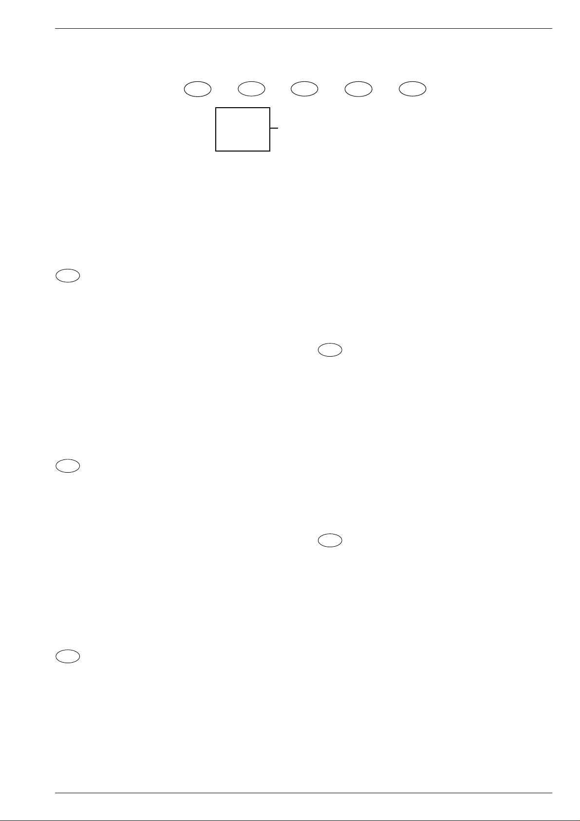
Eléments de commande
Information:
Ce chapitre contient des extraits du mode d'emploi. Pour toutes informations
supplémentaires veuillez vous référer au mode d'emploi spécifique à chaque
appareil, dont le numéro de référence est indiqué dans la liste de pléces
détachées.
Attribuer les positions de programme
l
3
Sécurité et installation
l
2
1ère possibilité
❒
Recherche automatique ATS (Auto Tuning System)
Le système de recherche automatique ATS balaye la plage de réception
dans sa totalité et mémorise automatiquement tous les émetteurs trouvés.
Procédez comme suit:
Mettez l’appareil en service à partir de la veille avec une des touches 1...9.
Appuyez pendant 4 s environ sur la touche PC/AUX jusqu’à ce que le menu
ATS apparaisse.
Lancez la recherche par la touche OK.
L’opération de recherche peut durer une minute ou plus longtemps.
Votre téléviseur est alors prêt à l’utilisation.
Nous vous souhaitons beaucoup de plaisir avec votre noveau téléviseur.
Si l’attribution automatique des émetteurs ne vous convient pas, vous pouvez déplacer les émetteurs sur les positions de programme de votre choix.
❒
Déplacer les émetteurs
Exemple: L’émetteur mémorisé sur la position de programme 5 doit être
déplacé sur la position de programme 2.
Sélectionnez la position de programme 2.
Appuyez sur la touche PC/AUX. Le menu programmes s’affiche.
Sous «PR», entrez la position de programme 05 avec les touches 1...9.
Appuyez sur OK. Le réglage est terminé.
Appuyez sur la touche i pour retourner en mode télé.
2ème possibilité
❒
Attribuer manuellement les positions de programme
Appuyez sur la touche PC/AUX. Le menu programmes s’affiche.
Sous «PR» sélectionnez la position de progamme à attribuer par P+/P- .
" «CH» entrez le numéro de canal (dans le cas d’un canal spécial,
entrez «C» au lieu de «S» avec la touche P+).
Si vous entrez le canal 00 sur une position de programme,
les positions suivantes ne peuvent plus être sélectionnées
par les touches P+ et P- .
2
PR CH S DEC FT
22 S06 I ON 00
0…9
&&%%
"! OK i
1
5
4
3
2
1
3
2
1
i
ligne dialogue
Page 12
1 - 12 GRUNDIG Service
Allgemeiner Teil / General Section
CUC 7301
Raccorder un magnétoscope ou un récepteur satellite
❒
Raccordement
Raccordez le magnétoscope ou le récepteur satellite à l’aide d’un câble
péritélévision à la prise AV sur l’arrière du téléviseur.
❒
Réglages à effectuer sur l’appareil raccordé
Lancez la lecture sur le magnétoscope ou mettez en service le récepteur
satellite.
w
!
L’appareil est conforme aux consignes de sécurité VDE et aux règlements
de la poste allemande (référence de l’autorisation: voir autocollant signalétique sur la face arrière de l’appareil), concernant la réglementation sur
la protection contre les dommages causés par des rayonnements X. Le
rayonnement X - émis par le tube cathodique - et complètement arrêté et
rendu ainsi totalement inoffensif. Tension d’accélération max. 25kV/courant
du faisceau moyen 0,8 mA. Des interventions inappropriées et notamment
la modification de la haute-tension ou le montage d’un autre type de tube
cathodique, peuvent provoquer une forte augmentation du rayonnement X.
Les appareils ainsi modifiés ne correspondent plus à cette autorisation et ne
doivent plus être mis en service.
220-240V, 50/60Hz (plage de réglage du bloc-secteur 165 – 265V).
Consommation env. 40 W; en veille 11 W.
Etage de sortie: 2 W puissance musicale (1 W sinusoïdale).
Le câble secteur est enfichable. Pour un remplacement, commandez,
auprès d’un service après-vente, avec le numéro de sujet 8290-991-307.
Sous réserve d’erreurs et de modifications. S.E. ou O.
1
1
Possibilités de raccordement
l
5
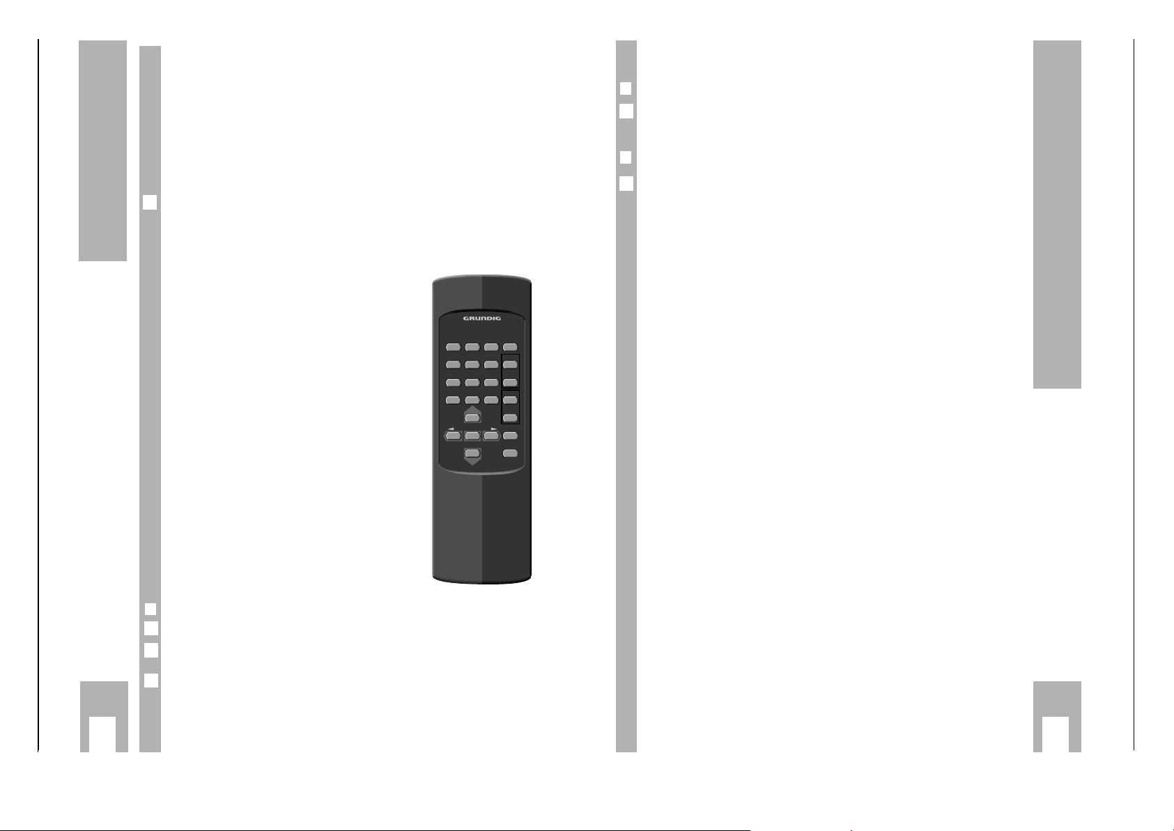
La télécommande
l
4
Les touches de la télécommande
1…9 (0/AV) Sélectionner des positions
de
programmes (aussi AV);
mise en service depuis la veille.
8
Commuter en veille et remettre
en service.
R
Luminosité
TXT Télétexte marche/arrêt.
E
Contraste couleur
i
Afficher le n° de programme.
Afficher l’aperçu Télétexte.
+ Son marche/arrêt
P+, P–
Sélectionner programmes;
déplacer le curseur.
OK
Modifier et activer diverses fonctions.
– z,+ t Volume;
déplacer le curseur.
PC/AUX Appeler des données de programme;
maintenirla touche enfoncée pendant
" «S» Standard TV; Pour les émissions en SECAM/L, sélectionnez
«L», pour celles en PAL/I, sélectionnez «I».
" «DEC»Si un programme crypté (p.ex. Canal+) est placé sur cette posi-
tion de programme et un décoder correspondant est raccordé, il
faut sélectionner «ON».
" «FT» Si un accord fin est nécessaire après l’attribution des program-
mes, appuyez sur la touche r – jusqu’à ce que les chiffres audessous de FT deviennent vert. Puis appuyez sur P+ ou P–
jusqu’à ce que la meilleure qualité d’image et de son soit
obtenue.
Sélectionnez OK pour mémoriser les valeurs modifiées.
Après la mémorisation, les données de programme de la position de programme suivante sont affichées.
3
❒
D’autres fonctions
Modifier le contraste n/b: Appuyer sur i, OK, – z ou + t.
Entrer une heure d’arrêt (01…99 min.) :
Appuyer sur
i, OK, i et les touches numériques 1…9.
Réglage fin automatique en/hors service:
Appuyer sur
i, OK, i, i puis sélectionner avec – z.
w
!
Toute valeur modifiée (volume, etc.) est mémorisée au bout de 8 s environ.
w
!
Une pression double sur la touche OK récupère les valeurs préréglées en usine.
3
2
1
12
4
56
789
PC/AUX
0/AV TXT
P+
OK
P–
8
3
+
R
–
+
E
–
6
+–
+
TP 711
Page 13

CUC 7301 F Partie générale / General Section
Fonctions de service et f onctions spéciales
1. Fonctions spéciales
1.1 Mémorisation des valeurs analogiques
Les valeurs analogiques introduites sont automatiquement
mémorisées après env. 8 secondes ou lors de la commutation en
veille.
1.2 Pour régler les valeurs optimales,
En appuyant sur les touches "OK" –> "OK" les valeurs optimales de
luminosité, contraste, couleur et volume sont réglées.
Valeur optimale Valeur maximale
Luminosité 43 63
Contraste couleur 45 63
Echelle des gris 50 63
Volume 30 63
Après mémorisation du volume minimum, l'échelle de réglage du
volume de l'OSD s'affiche pendant env. 8 secondes comme indication
visuelle .
1.3 Lancer ATS
Maintenir appuyée la touche "P/C"/AUX" pour afficher "ATS" (Auto
Tuning System), confirmer par "OK" .
Le système ATS mémorise automatiquement le signal de l'émetteur
trouvé (Affichage: Canal et Réglage fin)
1.4 Numéro de programme maximum (Point d'inversion C 00):
Appuyer sur la touche "PC/AUX" et introduire le numéro de canal "00"
sur une position de programme quelconque par le Menu Canal. Ainsi,
en Mode Programme,les programmes suivants ne peuvent plus être
sélectionnés par les touches 21. Si le point d'inversion est ≤ 10 seule
la sélection de dispositions de programmes à un chiffre est possible.
1.5 Appel du Menu Service lorsque "Hotel mode on" est activé
Maintenir appuyée la touche "6" de la télécommande et allumer
l'appareil par l'inter secteur. Avec les touches 21 sélectionner le Mode
Hôtel par le Menu et avec les touches 4 3 se positionner sur "OFF".
Lorsque le "Mode Hôtel" est activé il n'est plus possible d'appeler le
Menu Canal par la touche "PC/AUX".
1.6 Commutation 50Hz ou 60Hz en fonction HF (seul. TV avec NTSC)
En position programme, appuyer sur la touche "PC/AUX" et sélectionner la commutation de norme avec les touches 4 3 . A l'aide des
touches 21 se positionner sur "NT" pour la fonction NTSC.
1.7 Commutation 50Hz ou 60Hz en fonction AV
En position AV, appuyer sur la touche "PC/AUX" et avec les touches
21 se positionner sur "NTSC ON / OFF".
2. Réglages par le Menu Service
2.1 Pour appeler le Menu Service
Maintenir appuyée la touche "6" de la télécommande et allumer
l'appareil par l'inter secteur.
2.2 Réglage CAG-HF
Sélectionner "CAG ALIGN" par le Menu Service. Réglable à l'aide des
touches 4 3 entre les valeurs 0…63. Voir alignement 3-1 (6.).
2.3 Référence AFC
Sélectionner "AFC ALIGN" par le Menu Service. Confirmer par les
touches 4 ou 3 .
Par la validation de la fonction AFC-Référence un niveau de tension FI
est prélevé à la sortie AFC de l'IC150-(9) pour être attribué comme
référence en recherche d'émetteurs. Voir alignement 3-1 (5., 5a., 6.).
2.4 Position OSD
Maintenir appuyée la touche "6" de la télécommande et allumer
l'appareil par l'inter secteur. Sélectionner "OSD POSITION" par le
Menu Service et à l'aide des touches 4 3 placer le tableau de menu
OSD en position médiane.
(seul. TV avec NTSC)
Special and Service Functions
1. Special Functions
1.1 Storing the Analog Values
The entered analog values are either stored automatically after approx.
8 seconds or when switching to standby mode.
1.2 Setting the Optimum Values
Pressing "OK" –> "OK" the television receiver is set to the optimum
values stored for brightness, contrast, colour contrast and volume.
Optimum Maximum
Brightness 43 63
Colour contrast 45 63
BW contrast 50 63
Volume 30 63
Having stored the minimum volume level, the volume setting bar is
indicated on the screen for approx. 8 seconds as an optical information
when switching the power "on" or switching on from standby.
1.3 ATS Start
Press and hold the "P/C"/AUX" button until "ATS" (Auto Tuning
System) is indicated and confirm with "OK".
The ATS system tunes in the found station signal stores it automatically
(display: channel and finetuning).
1.4 Maximum Programme Number (reversing point C 00):
Press the "PC/AUX" button and enter the channel number "00" at any
programme position via the station channel menu. As a result of this,
programme selection with the 21 buttons in programme mode is
limited to the numbers lower than this position. If this reversing point is
≤ 10 only one-place programme selection is possible.
1.5 Calling up the Service Menu at "Hotel mode on"
Press and hold button "6" on the remote control and switch on with the
mains button. With the 21 buttons select the Hotel Mode in the menu
and set the indication to "OFF" using the 4 3 buttons.
During the time the "Hotel mode" is active it is not possible to call up the
station channel menu with the "PC/AUX" button.
1.6 Switching between 50Hz and 60Hz on HF Mode (only NTSC sets)
On programme mode press the "PC/AUX" button and select the standards selection menu item with 4 3. With the 21 buttons switch the
indication to "NT" for the NTSC television system.
1.7 Switching between 50Hz and 60Hz on AV Mode (only NTSC sets)
On AV mode, press the "PC/AUX" button and with the 21 buttons set
the indication to "NTSC ON / OFF".
2. Settings via the Service Menu
2.1 Calling up the Service Menu
Press and hold button "6" on the remote control and switch on with the
mains button.
2.2 AGC Alignment
Select "AGC ALIGN" in the Service Menu. Alignment is possible in
range 0...63 with the 4 3 buttons. See Alignment 3-2 (6.).
2.3 AFC Alignment
Select "AFC ALIGN" in the Service Menu. Confirm with 4 or 3 .
On activation of the AFC Reference, a rectified IF voltage is measured
at the AFC output of IC150-(9) which is used on station search as a
comparative value. See Alignment 3.2 (5., 5a., 6.).
2.4 OSD Position
Press and hold button "6" on the remote control and switch on with the
mains button. Select "OSD POSITION" in the Service Menu and with
the 4 3 buttons position the menu table in the centre of the screen.
GRUNDIG Service 1 - 13
Page 14

Partie générale / General Section CUC 7301 F
2.5 Pour activer le Mode Hôtel
Sélectionner "Hotel ON" par le Menu Service. Lorsque "Mode Hôtel"
est activé:
L'appel du Menu Canal par la touche "PC/AUX" n'est plus possible.
Dans ce mode, le volume présentement réglé est mémorisé comme
volume maximum.
2.6 Décodeur
Par le Menu Service commuter le décodeur sur "ON" ou "OFF" .
Décodeur "ON":
Identification automatique de la tension de commutation lente de la
broche 8 de l'embase EURO-AV (par ex. pour la fonction d'un
désembrouilleur sur les appareils FR, ou pour la fonction RVB ext. on/
off pour l'Italie).
2.7 Affichage permanent du numéro de programme
Pour l'affichage permanent du programme appuyer sur la touche"6".
Après env. 8 s la taille de l'indication de programme est réduite.
3. Réglages par le Menu Info
3.1 Indication de l'état de configuration
En appuyant brièvement sur la touche "6" de la télécommande on
affiche l'indication du programme puis par "OK" on entre dans le Menu.
3.2 Pour appeler le réglage du contraste
Par la touche de télécommande "6" puis –> OK on appelle le réglage
du contraste. Voir le § 1.2 pour régler les valeurs optimales .
3.3 Pour appeler le Timer (Horloge programmable)
Par les touches de télécommande "6" –> OK –> "6" on appelle le Timer.
A l'aide des touches numériques de la télécommande introduire
l'heure d'arrêt souhaitée.
2.5 Activating the Hotel Mode
Select "Hotel ON" in the Service Menu. When the "Hotel Mode" is
activated:
it is no longer possible to call up the station channel menu with the
"PC/AUX" button.
the currently set volume level is stored as the maximum level
possible in this mode.
2.6 Decoder
Via the Service Menu switch the decoder "ON" or "OFF".
Decoder "ON":
Automatic identification of the switching voltage at Pin 8 of the EUROAV socket (e.g. on descrambler operation with TVs marketed in
France, or external RGB mode on/off for Italy).
2.7 Continuous Station Ident Indication
So that the programme name is displayed continuously press the "6".
After about 8 seconds the programme is displayed in reduced size.
3. Settings via the Info Menu
3.1 Indication of the Status
Pressing the remote control button "6" for a short time call up the programme indication and makes it possible to enter the menu with "OK".
3.2 Calling up the Contrast Setting Option
Pressing the remote control buttons "6" –> OK calls up the contrast
setting option. See Optimum Values 1.2.
3.3 Calling up the Timer
To call up the timer press the remote control buttons "6" –> OK –> "6".
Enter the desired stop time with the numbered buttons on the remote
control.
3.4 Pour appeler la correction automatique du CAF "ON / OFF"
Appuyer sur les touches "6" –> OK –> "6" –> "6" de la télécommande
pour obtenir l'affichage CAF.
En activant "AFC ON" on lance la correction automatique de
syntonisation du tuner TV en cas de variations de la fréquence de
réception . Celle-ci est très utile en cas d'injection d'un signal vidéo par
la prise d'antenne.
3.4 Calling up the Automatic Frequency Control AFC "ON / OFF"
Press the remote control buttons "6" –> OK –> "6" –> "6" until the AFC
alignment option is displayed.
With "AFC ON", the function for automatic re-tuning of the TV tuner is
activated for correcting variations of the reception frequency. This
function is useful when feeding in a video signal via the aerial socket.
1 - 14 GRUNDIG Service
Page 15
CUC 7301 F Partie générale / General Section
Tableaux des normes et des canaux / Tables of Norms and Channels
Bande III / Band III, Norme K 1 / Norm K 1
Ecart son/image / Sound/vision spacing: 6,5MHz
Pas des canaux / Channel bandwidth: 8MHz
Affichage /
Display
C4
C5
C6
C7
C8
C9
Bande IV et V / Band IV and V, Norme L / Norm L
Ecart son/image / Sound/vision spacing: 6,5MHz
Pas des canaux / Channel bandwidth: 8MHz
Affichage /
Display
C21
C22
C23
C24
C25
C26
C27
C28
C29
C30
C31
C32
C33
C34
C35
C36
C37
C38
C39
C40
C41
C42
C43
C44
C45
C46
C47
C48
C49
C50
C51
C52
C53
C54
C55
C56
C57
C58
C59
C60
C61
C62
C63
C64
C65
C66
C67
C68
C69
N° canal / Channel no.
4
5
6
7
8
9
N° canal / Channel no.
21
22
23
24
25
26
27
28
29
30
31
32
33
34
35
36
37
38
39
40
41
42
43
44
45
46
47
48
49
50
51
52
53
54
55
56
57
58
59
60
61
62
63
64
65
66
67
68
69
Fréquence image /
Vision carrier frequency
175,25MHz
183,25MHz
191,25MHz
199,25MHz
207,25MHz
215,25MHz
Fréquence image /
Vision carrier frequency
471,25MHz
479,25MHz
487,25MHz
495,25MHz
503,25MHz
511,25MHz
519,25MHz
527,25MHz
535,25MHz
543,25MHz
551,25MHz
559,25MHz
567,25MHz
575,25MHz
583,25MHz
591,25MHz
599,25MHz
607,25MHz
615,25MHz
623,25MHz
631,25MHz
639,25MHz
647,25MHz
655,25MHz
663,25MHz
671,25MHz
679,25MHz
687,25MHz
695,25MHz
703,25MHz
711,25MHz
719,25MHz
727,25MHz
735,25MHz
743,25MHz
751,25MHz
759,25MHz
767,25MHz
775,25MHz
783,25MHz
791,25MHz
799,25MHz
807,25MHz
815,25MHz
823,25MHz
831,25MHz
839,25MHz
847,25MHz
855,25MHz
Bande I / Band I, Norme L´ / Norm L´
Ecart son/image / Sound/vision spacing: 6,5MHz
Pas des canaux / Channel bandwidth: 8MHz
Affichage /
Display
C2
C3
C4
Bande III / Band III, Norme L´ / Norm L´
Ecart son/image / Sound/vision spacing: 6,5MHz
Pas des canaux / Channel bandwidth: 8MHz
Affichage /
Display
C5
C6
C7
C8
C9
C10
Interbande / Special channels, Norme L / Norm L
Ecart son/image / Sound/vision spacing: 6,5MHz
Pas des canaux / Channel bandwidth: 12MHz
Affichage /
Display
S5
S6
S7
S8
S9
S10
S11
S12
S13
S14
S15
S16
S17
S18
S19
S20
Hyperbande Euro / Special channels, Norme L / Norm L
Ecart son/image / Sound/vision spacing: 6,5MHz
Pas des canaux / Channel bandwidth: 8MHz
Affichage /
Display
S21
S22
S23
S24
S25
S26
S27
S28
S29
S30
S31
S32
S33
S34
S35
S36
S37
S38
S39
S40
S41
N° canal / Channel no.
2
3
4
N° canal / Channel no.
5
6
7
8
9
10
N° canal / Channel no.
B
C
D
E
F
G
H
I
J
K
L
M
N
O
P
Q
N° canal / Channel no.
S21
S22
S23
S24
S25
S26
S27
S28
S29
S30
S31
S32
S33
S34
S35
S36
S37
S38
S39
S40
S41
Fréquence image /
Vision carrier frequency
55,75MHz
60,50MHz
63,75MHz
Fréquence image /
Vision carrier frequency
176,00MHz
184,00MHz
192,00MHz
200,00MHz
208,00MHz
216,00MHz
Fréquence image /
Vision carrier frequency
116,75MHz
128,75MHz
140,75MHz
152,75MHz
164,75MHz
176,75MHz
188,75MHz
200,75MHz
212,75MHz
224,75MHz
236,75MHz
248,75MHz
260,75MHz
272,75MHz
284,75MHz
296,75MHz
Fréquence image /
Vision carrier frequency
303,25MHz
311,25MHz
319,25MHz
327,25MHz
335,25MHz
343,25MHz
351,25MHz
359,25MHz
367,25MHz
375,25MHz
383,25MHz
391,25MHz
399,25MHz
407,25MHz
415,25MHz
423,25MHz
431,25MHz
439,25MHz
447,25MHz
455,25MHz
463,25MHz
GRUNDIG Service 1 - 15
Page 16

Partie générale / General Section CUC 7301 F
Bande I / Band I, Norme B / Norm B
Ecart son/image / Sound/vision spacing: 5,5MHz
Pas des canaux / Channel bandwidth: 7MHz
Affichage /
Display
C2
C3
C4
N° canal / Channel no.
E2
E3
E4
Fréquence image /
Vision carrier frequency
48,25MHz
55,25MHz
62,25MHz
Bande IV et V / Band IV and V, Norme G / Norm G
Ecart son/image / Sound/vision spacing: 5,5MHz
Pas des canaux / Channel bandwidth: 8MHz
Affichage /
Display
C21
C22
C23
C24
C25
C26
C27
C28
C29
C30
C31
C32
C33
C34
C35
C36
C37
C38
C39
C40
C41
C42
C43
C44
C45
C46
C47
C48
C49
C50
C51
C52
C53
C54
C55
C56
C57
C58
C59
C60
C61
C62
C63
C64
C65
C66
C67
C68
C69
N° canal / Channel no.
21
22
23
24
25
26
27
28
29
30
31
32
33
34
35
36
37
38
39
40
41
42
43
44
45
46
47
48
49
50
51
52
53
54
55
56
57
58
59
60
61
62
63
64
65
66
67
68
69
Fréquence image /
Vision carrier frequency
471,25MHz
479,25MHz
487,25MHz
495,25MHz
503,25MHz
511,25MHz
519,25MHz
527,25MHz
535,25MHz
543,25MHz
551,25MHz
559,25MHz
567,25MHz
575,25MHz
583,25MHz
591,25MHz
599,25MHz
607,25MHz
615,25MHz
623,25MHz
631,25MHz
639,25MHz
647,25MHz
655,25MHz
663,25MHz
671,25MHz
679,25MHz
687,25MHz
695,25MHz
703,25MHz
711,25MHz
719,25MHz
727,25MHz
735,25MHz
743,25MHz
751,25MHz
759,25MHz
767,25MHz
775,25MHz
783,25MHz
791,25MHz
799,25MHz
807,25MHz
815,25MHz
823,25MHz
831,25MHz
839,25MHz
847,25MHz
855,25MHz
Bande III / Band III, Norme B / Norm B
Ecart son/image / Sound/vision spacing: 5,5MHz
Pas des canaux / Channel bandwidth: 7MHz
Affichage /
Display
C5
C6
C7
C8
C9
C10
C11
C12
N° canal / Channel no.
E5
E6
E7
E8
E9
E10
E11
E12
Fréquence image /
Vision carrier frequency
175,25MHz
182,25MHz
189,25MHz
196,25MHz
203,25MHz
210,25MHz
217,25MHz
224,25MHz
Interbande / Special channels, Norme B / Norm B
Ecart son/image / Sound/vision spacing: 5,5MHz
Pas des canaux / Channel bandwidth: 7MHz
Affichage /
Display
S1
S2
S3
S4
S5
S6
S7
S8
S9
S10
S11
S12
S13
S14
S15
S16
S17
S18
S19
S20
N° canal / Channel no.
S1
S2
S3
S4
S5
S6
S7
S8
S9
S10
S11
S12
S13
S14
S15
S16
S17
S18
S19
S20
Fréquence image /
Vision carrier frequency
105,25MHz
112,25MHz
119,25MHz
126,25MHz
133,25MHz
140,25MHz
147,25MHz
154,25MHz
161,25MHz
168,25MHz
231,25MHz
238,25MHz
245,25MHz
252,25MHz
259,25MHz
266,25MHz
273,25MHz
280,25MHz
287,25MHz
294,25MHz
Hyperbande Euro / Special channels, Norme G / Norm G
Ecart son/image / Sound/vision spacing: 5,5MHz
Pas des canaux / Channel bandwidth: 8MHz
Affichage /
Display
S21
S22
S23
S24
S25
S26
S27
S28
S29
S30
S31
S32
S33
S34
S35
S36
S37
S38
S39
S40
S41
N° canal / Channel no.
S21
S22
S23
S24
S25
S26
S27
S28
S29
S30
S31
S32
S33
S34
S35
S36
S37
S38
S39
S40
S41
Fréquence image /
Vision carrier frequency
303,25MHz
311,25MHz
319,25MHz
327,25MHz
335,25MHz
343,25MHz
351,25MHz
359,25MHz
367,25MHz
375,25MHz
383,25MHz
391,25MHz
399,25MHz
407,25MHz
415,25MHz
423,25MHz
431,25MHz
439,25MHz
447,25MHz
455,25MHz
463,25MHz
1 - 16 GRUNDIG Service
Page 17
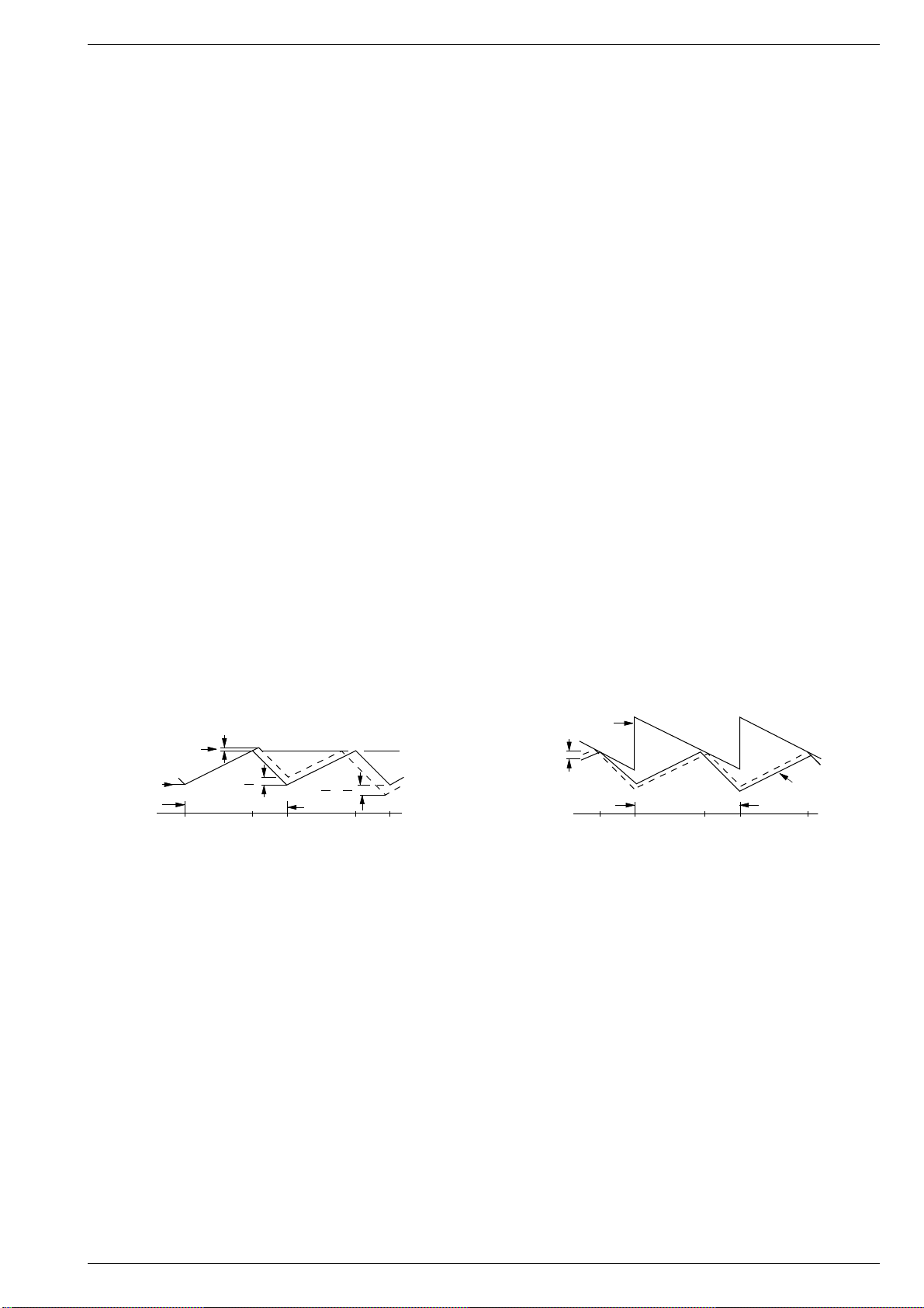
CUC 7301 F
Description des circuits / Circuit Description
Description des circuits
1. Le C.I. Alimentation
1.1 Principe de fonctionnement du circuit
Les alimentations à découpage peuvent produire des oscillations
subharmoniques lorsqu'elles fonctionnent à une cadence > 50% avec
un courant d'induction continu. Cette instabilité est indépendante des
caractéristiques des circuits de régulation fermés et peut être engendrée par la mesure simultanée de la fréquence fixe et du courant de
crête.
La Fig. 1 présente ce phénomène sous forme graphique. Au moment
t0 commence la mise en circuit et le courant d'induction augmente avec
une pente m1. Cette montée est une fonction de la tension d'entrée par
rapport à l'inductance. Au moment t1 l'intensité de courant déterminée
par la tension de commande est au maximum. La phase de blocage est
alors engagée et le courant chute selon la courbe m2 jusqu'au prochain
cycle d'oscillation. Cette instabilité est démontrée lorsqu'on additionne
un signal parasite à la tension de commande. Il en résulte le léger
décalage de courant DI (ligne pointillée). Dans le cas d'une durée
d'oscillation fixe, la phase de blocage est diminuée et l'intensité de
courant minimum pendant la phase de conduction (t2) s'accroît de DI
+ DI m2/m1. L'intensité de courant minimum au cycle suivant (t3) chute
à (Dl + Dl m2/m1) (m2/m1). Cette valeur parasite se multiplie à chaque
cycle suivant par m2/m1 de sorte que le courant d'induction croît et
décroît alternativement au moment de l'inversion de polarité. Pour que
le courant d'induction devienne nul plusieurs cycles d'oscillation sont
nécessaires. Ensuite le processus recommence au début. Si m2/m1 est
supérieur à 1, l'alimentation à découpage devient instable. Lorsqu'on
additionne à la tension de commande une tension artificielle en dent de
scie synchronisée avec la cadence du modulateur de largeur d'impulsion comme indiqué sur la Fig.1, la valeur parasite DI diminue lors des
cycles suivants pour devenir nulle. Afin d'obtenir une stabilité, la pente
de cette tension de correction doit être égale ou légèrement supérieure
à m2/2. Si la tension de correction est de m2/2, le courant d'induction
moyen s'aligne sur la tension de commande de façon à obtenir une
réelle régulation de courant. La tension de correction est dérivée
depuis l'oscillateur pour être dirigée soit vers l'entrée de tension de
rétrocouplage soit vers l'entrée de mesure de courant (Fig. 2).
m1
t
0
∆l
∆l + ∆l
Oscillator Period
Fig. 1
Control Voltage
Inductor
Current
1.2 Fonctionnement normal / Fonctionnement en régulation
L'alimentation à découpage du téléviseur fonctionne à une fréquence
d'env.50kHz (en charge normale et pour une tension de 230V secteur).
Le circuit collecteur du transistor de puissance T665 reçoit via
l'enroulement primaire 2/1 du transformateur à découpage TR601 la
tension redressée par D621…D624. Avec 230V secteur,une tension
d'env. +320V charge le condensateur C626.
L'IC630 commande le transistor de puissance bipolaire T665 et contrôle
toutes les fonctions de régulation et de mise en sécurité. La tension
d'alimentation (pin 7) de l'IC de régulation est d'env.12V. Après avoir reçu la
tension de démarrage à la pin 7 par la résistance R633, et le condensateur
C667, l'IC délivre à la pin 6 une impulsion positive de démarrage (1µs) de
10Vcc. Après la phase de démarrage de l'IC la tension d'alimentation est
relayée par l'enroulement 3/4 du tranformateur via la diode D667. Pendant
la conduction du transistor l'énergie est accumulée dans le transformateur
et pendant la période de blocage celle-ci est restituée aux enroulements du
secondaire. L'IC630 détermine par la pin 6 la fréquence et la tension de
commutation du transistor T665 de façon à obtenir au secondaire des
tensions stables indépendantes des fluctuations du secteur et des variations
de charge.
Le transistor de puissance T665 commande un modulateur de largeur
d'impulsion cadencé par un oscillateur intégré dans l'IC. La fréquence est
déterminée par les composants C652 et R652. Pour la stabilisation l'IC630
compare la tension de réaction redressée par D654 avec la tension de
référence 5V de l'IC630-(8). Si la tension de réaction diminue légèrement
suite à une augmentation de la charge, la largeur de l'impulsion de
commande du transistor T665 augmente. Ainsi la durée de conduction de
m2
m
2
m
1
t
1t2
(A)
∆l + ∆l
())(
m
m
2
2
m
m
1
1
t
3
Description
1. Power Supply
1.1 Basic Circuit
Current mode converters can exhibit subharmonic oscillations when
operating at a duty cycle greater than 50% with continuous inductor
current. This instability is independent of the regulators closed loop
characteristics and is caused by the simultaneous operating conditions
of fixed frequency and peak current detecting.
Figure 1 shows the phenomenon graphically. At t0, switch conduction
begins, causing the inductor current to rise at a slope of m1.This slope
is a function of the input voltage divided by the inductance. At t1, the
Current Sense Input reaches the threshold established by the control
voltage. This causes the switch to turn off and the current to decay at
a slope of m2, until the next oscillator cycle. The unstable condition can
be shown if a pertubation is added to the control voltage, resulting in
a small ∆l (dashed line). With a fixed oscillator period, the current decay
time is reduced, and the minimum current at switch turn-on (t2) is
increased by ∆l + ∆l m2/m1. The minimum current at the next cycle (t3)
decreases to (∆l + ∆l m2/m1) (m2/m1). This pertubation is multiplied by
m2/m1 on each succeeding cycle, alternately increasing and decreasing the inductor current at switch turn-on. Several oscillator cycles may
be required before the inductor current reaches zero causing the
process to commence again. If m2/m1 is greater than 1, the converter
will be unstable. Figure 1 shows that by adding an artificial ramp that
is synchronized with the PWM clock to the control voltage, the ∆l
pertubation will decrease to zero on succeeding cycles. This compensating ramp (m3) must have a slope equal to or slightly greater than m2/
2 for stability. With m2/2 slope compensation, the average inductor
current follows the control voltage yielding true current mode operation. The compensating ramp can be derived from the oscillator and
added to either the Voltage Feedback or Current Sense inputs (Figure 2).
Fig. 2
Control Voltage
∆l
t
45
1.2 Normal / Controlled Operation
For the power supply of this TV receiver a blocking oscillator-type
converter power supply with a switching frequency of 50kHz approximately is used (at normal operation and a mains voltage of 230V).
The collector contact of the power transistor T665 is connected via the
primary winding 2/1 of the blocking oscillator-type transformer TR601
to the rectified mains voltage, D621…D624. At a mains voltage of 230V
the voltage level present at the charging electrolytic capacitor C626 is
approx. +320V.
The IC630 is responsible for driving, controlling and monitoring the
bipolar power transistor T665. The supply for the control-IC is 12V and
is present on Pin 7. As soon as the switch-on threshold is reached on
Pin 7 via the resistor R633 and the capacitor C667, the IC feeds out a
positive start pulse (1µs) of 10V pp at Pin 6. After start-up of the IC, the
supply voltage is obtained via the diode D667 from the winding 3/4 of
the transformer. During the conducting phase of the transistor, energy
is stored in the transformer and this is transferred into the secondary
winding when the transistor is switched off. The IC630 controls by the
period during which the transistor T665 is switched on, the transfer of
energy at Pin 6 so that the secondary voltages are stable and are
largely not affected by variations of the mains supply, mains frequency
and the load.
The power transistor T665 is driven by a pulse-width modulator which
is triggered by an oscillator integrated in the IC. The frequency of the
oscillator is determined by the components C652 and R652. For
stabilisation, the feedback voltage which is rectified by D654 is
compared in IC630 with the 5V reference voltage provided at IC630-(8).
m3
m1
Oscillator Period
(B)
m2
tt
Inductor
Current
6
GRUNDIG Service
2 - 1
Page 18

Description des circuits / Circuit Description
CUC 7301 F
T665 s'allonge et de ce fait une plus grande quantité d'énergie est transmise
pour la compensation de la charge. L'entrée de régulation du courant se
trouve à l'IC630-(3). En cas d'augmentation de consommation de courant
côté secondaire, la commande du transistor T665, IC630-(6), est interrompue via l'entrée de régulation pin 3.
En cas de court-circuit du transistor T665 le circuit UC3842 serait
détruit. C'est pourquoi les diodes D666 et D664 contrôlent la tension
de la pin 3 et la limitent à 1,2V maximum. Les composants D668, C669
et R669 fonctionnent comme un circuit anti suroscillations.
Les composants CD654, C656, CD656 et CR656 provoquent un
accroissement progressif des impulsions de commande (Soft-Start).
A l'aide de l'ajustable R654 les tensions du secondaire sont réglées par
l'intermédiaire du contrôle de la tension +A, la luminosité et le contraste
étant au minimum.
1.3 Fonctionnement en veille
En fonctionnement normal une tension d'env.10,5V est disponible à l'IC676-(1)
(LM317). Si l'appareil doit être commuté en veille, le µP passe la tension
U
à l'état "Haut" et ainsi la tension à l'IC676-(1) est < 0,7V. De la sorte la
Stanby
tension +B est interrompue et l'appareil commute en veille.
1.4 Tensions du côté secondaire
+A: Tension d'alimentation pour l'étage de déviation horizontale
provenant de l'enroulement 5/9 et D682. Le C.I. alimentation
est réglé sur cette valeur.
+33V: La tension de syntonisation pour le tuner est obtenue à la
diode Zener D683 et la résistance R681 depuis l'enroulement
5/9 via D682.
+M =16,5V Tension d'alimentation pour l'étage final audio provenant
de l'enroulement 7/5 et redressée par D671.
+B =12V Tension d'alimentation pour le tuner et l'étage pilote hori
zontal T501. Cette tension provient de l'enroulement 7/5,
traverse la diode D671 et se stabilise par le contrôleur
IC676. Pour l'interruption du +12V voir "Fonctionnement
en veille".
+E = 8V Tension d'alimentation du processeur vidéo IC150. Celle-
ci est coupée en fonction veille.
+H = 5V Tension d'alimentation pour le µP IC850, l'ampli infra
rouge IR810, le télétexte IC2810, le tuner et le CIC105.
Cette tension est néanmoins présente en fonction veille.
If the feedback voltage decreases by a small amout due to a heavier
load the drive pulse to the transistor T665 is prolonged. As a result, the
conducting period of T665 will be longer so that additional energy
transfer will be provided to compensate for the load. Pin 3 of IC630 is
a current sense input and will stop the drive to T665 at IC630-(6) in the
event of excessive current drain from a heavy secondary load.
If there was a short circuit condition at the transistor T665, the circuit
UC3842 would be destroyed. Therefore, the diodes D666 and D664
are provided to avoid the voltage at pin 3 exceeding 1.2V. The
components D668, C669, and R669 work as a snap stage.
The components CD654, C656, CD656, and CR656 delay the rise of
the pulse start duration (soft start).
The adjustment control R654 is used to set the secondary voltages by
regulating the +A voltage at minimum brightness and contrast.
1.3 Standby Mode
In normal operating mode, a voltage of approx. 10.5V is present on
IC676-(1) (LM317). If the TV receiver is to be switched to standby, the
µP switches U
< 0.7 V. As a result, the voltage +B is switched off and the TV receiver
to "High" level so that the level on IC676-(1) is
Standby
goes to standby.
1.4 Secondary Voltages
+A: Supply for the horizontal output stage from the winding 5/9
and D682. The power supply unit is set to this level.
+33V: The upper tuning voltage limit for the tuner is produced at the
Z-diode D683 and the resistors R681 from the winding 5/9 via
D682.
+M =16.5V Supply for the sound output stage from the winding 7/5 and
the diode D671.
+B = 12V Power supply for the Tuner, SAT-module and the horizon-
tal driver T501. This voltage is supplied from the winding
7/5 via the diode D671 and is stabilised by the adjustment
control IC676. Switching off of the +12V supply, see
"Standby Operation".
+E = 8V Power supply for the Video Processor IC150. In Standby
mode it is switched off.
+H = 5V Power supply for the µP IC850, the infrared amplifier
IR810, the Videotext IC2810, Tuner, and CIC105.
This voltage is also present in Standby mode.
Tensions supplémentaires nécessaires
+D: 25V Tension d'alimentation pour l'étage de déviation ver
ticale provenant de l'enroulement du transformateur ligne
B/H via D444.
+C: 125V La tension d'alimentation pour le C.I. tube est fournie
190V depuis l'enroulement du transformateur ligne G/H par
l'intermédiaire de R543 et de la diode D543.
130V / tubes de 14"; 200V / tubes de 15"...21".
V
ref
R
T
C
T
Voltage Feedback
Input
Output
Compensation
8
4
2
1
2.5V
R
R
+
-
Error
Amplifier
Internal
Bias
Oscillator
1.0mA
2R
Gnd
3.6V
R
1.0V
5
Reference
Regulator
+
-
V
ref
UVLO
-
+
Current Sense
Compartator
Additionally necessary voltages
+D:25V Power supply for the vertical output stage from the line
transformer winding B/H via D444.
+C: 125V The power supply for the picture tube panel is obtained
190V from the line transformer winding G/H via R543 and the
diode D543. 130V/14" CRT; 200V/15…21" CRT.
UVLO
S
R
+
-
V
cc
Q
Vcc7
PWM
Latch
Sink Only
=
Positive True Logic
36V
V
cc
V
c
7
Output
6
Power Ground
5
Current Sense Input
3
V
in
T665
R
s
2 - 2
GRUNDIG Service
Page 19

CUC 7301 F
Description des circuits / Circuit Description
2. Le système de commande
2.1 Le microprocesseur
Le microprocesseur IC850 à 8 bits programmé par masque décode les
ordres depuis le clavier en façade ainsi que la télécommande via le
récepteur infrarouge IR. En outre il gère l'ensemble de la procédure de
fonctionnement du système et l'incrustation OSD sur l'écran. Toutes
les données de programme et les options sont mémorisées dans une
NVM (mémoire non volatile). Le transfert des données entre le télétexte
IC2810 et le tuner est réalisé par l'intermédiaire du Bus I2C.
Les conditions pour un fonctionnement correct du microprocesseur
sont les suivantes:
- Tension d'alimentation +5V/H aux pins 2, 19, 36
- Fréquence d'oscillateur 4MHz aux pins 39, 40
- Impulsion de Reset:
A chaque mise en marche par l'interrupteur secteur, une impulsion
de Reset sur la pin 1 initialise le microprocesseur.
- Bus I2C:
Le Bus I2C est un Bus bidirectectionnel à deux lignes composé de
la ligne SDA (Data série) et de la ligne SCL (Clock série).
Commande de fonctionnement du processeur IC850:
Les lignes du Bus I2C sont reliées via les résistances Pull-up CR869 et
CR868 au +5V/H. Le transfert des données est géré par le processeur
qui génère l'impulsion d'horloge SCL. Le contrôle des lignes de
données et d'horloge en maintenance n'est possible que par la mesure
du niveau TTL (Niveau bas L ≤ 0,8V; H ≥ 3,5V).
Recommandation pour la maintenance:
Les données du Bus I2C sont toujours présentes même sans aucun
ordre de télécommande IR. Si la mesure sur la ligne de données du
Bus I2C indique une absence de signal, cela peut provenir d'un courtcircuit. Afin de localiser l'origine du défaut, déconnecter ou dessouder
l'un après l'autre les circuits commandés par le Bus I2C.
2.2 Initialisation du calculateur à la mise en marche
Au moment de la mise en marche la tension +5V/H monte en charge,
l'IC850-(1) est initialisé et la séquence de programme est lancée.
Au moment de la commande de mise en marche, le processeur émet un état
"Haut" à la pin 14 et la tension U
IC676-(1) à l'aide des tensions +B, +12V (voir circuit d'alimentation).
Après la mise en marche de l'appareil, le processeur (IC850) transmet
les données de fonctionnement depuis la mémoire interne via le Bus
I2C vers les circuits et les modules contrôlés par le Bus.
2.3 La commutation du signal FBAS sur la prise Scart
Si la tension de commutation U
ci bascule le signal vidéo composite FBAS
(FBAS
) sur la sortie pin 19 de la prise Scart.
EURO-AV
2.4 Introduction des commandes
Le clavier de commande est relié à la tension permanente du +5V/H.
Par l'analyse des différents niveaux de tension, le processeur
IC850-(27), -(28) identifie la touche du clavier sélectionnée.
Les ordres de télécommande sont amplifiés par le récepteur infrarouge IC810 et décodés à la pin 8 du µP.
2.5 La fonction télétexte (Option)
L'IC2810 (SAA5254 P/E pour l'Europe de l'Ouest, SAA5254 P/H pour
l'Europe de l'Est) est un circuit intégré télétexte de 1 page. L'affichage
sur l'écran est subdivisé en lignes et en colonnes. Pour le positionnement
et la synchronisation de l'image télétexte, des impulsions de référence
horizontales et verticales sont acheminées à l'IC2810-(13), -(12).
L'activation du télétexte est effectuée par l'intermédiaire du Bus I2C. Le
SAA5254 interroge via la pin 8 le signal vidéo composite FBAS
sur la présence de données télétexte.
2.6 L'affichage OSD sur l'écran
En cas d'incrustation OSD, la tension de commutation "U
à l'état "Haut" et "commute" la voie RVB par l'intermédiaire de CT2832,
IC150-(21) £ 4V. Le générateur de caractères fournit les données d'affichage par l'intermédiaire des ports de sortie 16, 17 et 18 du µP avec une
amplitude d'env. 3,5V au C.I. tube (connexion RVB 1, 3, 5).
2.7 Le circuit de protection U
A la base du transistor T511 se tient via R511 le point de fuite de l'étage de
puissance verticale et via R512, D512, D513 le signal de comparaison F
provenant de l'étage de puissance horizontale. En cas de défaut, la tension
du circuit de base commute le transistor à partir de 0,6V et connecte via son
collecteur l'IC850-(22) à la masse. Ainsi, le µP commute l'appareil en veille.
Si la tension +D est absente, la tension continue à la sortie de l'étage
de puissance verticale IC400-(5) manque également de la sorte que
démarre le téléviseur via CT826,
Stanby
à l'IC850-(9) est à l'état Haut, celle-
FBAS
Schutz
de l'IC150-(13)
SC
", IC850-(21) est
Data
EURO-AV
2. System Control
2.1 Microcomputer
The mask-programmed 8-bit Microcomputer IC850 decodes the commands entered on the keyboard and also the infra-red remote control
commands from the IR-receiver. It is also responsible for the total
system control and the on-screen display (OSD). All data for the
programme positions and the options are stored in the NVM (Non
Volatile Memory). The data traffic between the teletext (Videotext)IC2810, and the tuner is carried on the I2C-bus.
The correct operation of the microcomputer depends on the following
conditions:
- Supply voltage +5V/H at Pins 2, 19, 36
- Oscillator frequency 4MHz at Pins 39, 40
- Reset pulse:
Every time the TV receiver is switched on with the mains button, the
processor is reset on Pin 1 by the reset pulse.
-I2C-bus:
The I2C-bus is a bidirectional two-lead bus consisting of the SDA
(System Data) lead and the SCL (System Clock) lead.
Checking the operation of the processor IC850:
The I2C-bus leads are connected via the pull-up resistors CR869 and CR868
to +5V/H. The data traffic is controlled from the processor which also
generates the SCL bus clock. The only way to check the data and clock leads
when servicing is by measuring the TTL-levels (L ≤ 0.8V; H ≥ 3.5V).
Service note:
The I2C-bus data is also present without a command from the IR remote
control handset. If no data is carried on the bus leads there may be a
short circuit. To localize the fault, the modules and components
connected to the data bus must be unsoldered or unplugged one after
the other.
2.2 Initialisation of the Processor after Switching On
When the TV is switched on, the +5V/H voltage builds up, the IC850-(1)
is reset, and the programme sequence is started.
With the start command, the processor feeds out a "High" level at
Pin 14 and the voltage U
means of the voltages +B, 12V (see Power Supply).
After switching on, the processor (IC850) transfers the operating data
from the internal memory via the I2C-bus to the bus-controlled modules
and circuits.
2.3 Switching over of the CCVS Signals to the Scart Socket
A "High"-level switching voltage U
signal FBASSC to be switched over from IC150-(13) (FBAS
output pin 19 of the Scart socket.
2.4 Entering Commands
The keyboard is connected to the unswitched voltage +5V/H. By
evaluating the different voltage levels, the processor IC850-(27), -(28)
knows which button on the keyboard has been pressed.
The remote control commands are amplified by the infrared receiver
IC810 and decoded at Pin 8 of the microprocessor.
2.5 Teletext (optionally)
The IC2810 (SAA5254 P/E for West Europe, SAA5254 P/H for East
Europe) is a 1-page Teletext-IC. The On Screen Display is subdivided
into lines and columns. For positioning and synchronising the teletext
display, horizontal and vertical reference pulses are fed to
IC2810-(13), -(12). Activation of the teletext is effected via the I2C-bus.
Via pin 8, the SAA5254 scans the CCVS signal FBAS
data.
2.6 On Screen Display (OSD)
For displaying data on the screen, the switching voltage "U
IC850-(21) supplies a "High" level and blanks the picture tube by
CT2832, IC150-(21) ≤ 4V. The character generator feeds out the
display data via the output ports 16, 17, 18 of the microprocessor at an
amplitude of 3.5V to the CRT base panel (contact RGB 1, 3, 5).
2.7 Protection Circuit U
The base of the transistor T511 is connected via R511 to the low-end
point of the vertical output stage, and via R512, D512, D513 to the
reference pulse F from the horizontal output stage. In the case of any
failure, a base voltage of 0.6V and higher switches the transistor on; via
its collector the transistor switches IC850-(22) to ground. The µP then
switches the TV to standby.
If the voltage +D fails there is no direct voltage present at the output of
the vertical output stage IC400-(5) and consequently the proctection
circuit input IC850-(22) is pulled to ground.
starts the TV via CT826, IC676-(1) by
Standby
at IC850-(9) causes the CCVS
FBAS
EURO-AV
Schutz
) to
EURO-AV
for teletext
Data
"
GRUNDIG Service
2 - 3
Page 20

Description des circuits / Circuit Description
CUC 7301 F
I'entrée du circuit de protection IC850-(22) est connectée à la masse.
Parallèlement au collecteur (ligne SB) se tient via R513, D514, CD516
le point de fuite de l'enroulement de haute tension. En cas de courant
de faisceau trop fort la tension Zener est dépassée et la tension du
circuit collecteur décroît vers 0V et ainsi l'appareil commute en veille.
3. Le processeur de signal TV TDA 8362A
3.1 Généralité:
Dans cette conception de TV, la presque totalité du traitement des
signaux est effectuée dans un seul circuit intégré c'est à dire le
processeur de signal TV TDA 8362A.
Celui-ci contient les étages suivants:
Signal FI:
- Ampli FI
- Démodulateur
- CAF
- CAG
- Identification de coïncidence
Signal vidéo composite FBAS:
- Commutation du signal de source pour le signal FBAS
- Traitement de la luminance
- Démodulation couleur
- Traitement de la chrominance
- Réglage du contraste couleur
- Matrice RVB
- Entrée C-AV
- Commutation du signal de source pour les signaux RVB
- Réglage de la luminosité
- Réglage du contraste
- Réglage de l'échelle des gris (Cut-off)
Signal audio
- Commutation du signal de source pour l'audio
- Démodulation du son
- Réglage du volume
Circuit de déviation:
- Séparateur synchro
- Oscillateur lignes
- Réglage de la phase ϕ1
- Réglage de la phase ϕ2
- Génération de l'impulsion synchro pour l'étage de puissance lignes
- Compteur de lignes
- Générateur de l'impulsion enpour l'étage de puissance verticale
- Signal d'attaque pour l'étage de puissance verticale
En outre, et en fonction de l'équipement des circuits, l'IC peut traiter les
signaux en standard PAL et SECAM.
3.2 Circuit FI
La FI provient sur une voie symétrique des pins 9 et 10 du tuner et traverse
le filtre à ondes de surface F906. Le signal obtenu dans le FOS est dirigé
symétriquement aux pins 45 et 46 du processeur de signal. La démodulation
du signal FBAS (vidéo composite) est effectuée dans un démodulateur de
produit. Le circuit annexe F130 nécessaire pour cette démodulation est relié
aux pins 2 et 3. Le circuit ainsi démodulé traverse un amplificateur pour être
disponible à la pin 7 de l'IC (BB). Celui-ci identifie le signal synchro en interne
sans référence à l'impulsion de retour lignes.Par ailleurs une tension de
régulation est générée en fonction du niveau synchro. Cette tension de
régulation intervient en premier lieu sur l'ampli régulé d'entrée de la FI. Puis
un seuil de référence URV est réglé par l'intermédiaire de la pin 49. En-deçà
de ce seuil, seul l'ampli d'entrée FI est réglé. En cas de dépassement de ce
seuil, la pin 47 applique la tension de régulation Ut au tuner. La pin 47 est une
sortie à collecteur ouvert. En cas de non régulation la valeur de la tension est
environ 5V. Lorsque l'amplitude d'entrée augmente, le niveau CAG diminue.
La tension continue nécessaire pour le CAF est générée dans le démodulateur.
La pin 9 délivre ce signal comme un courant de sortie. Si la fréquence de
réception augmente, la tension de régulation pour le CAF diminue. Le
processeur IC850 analyse ce signal et demande au tuner un réglage fin.A
partir du signal démodulé, le détecteur synchro vérifie la présence de signaux
synchro. Si ceux-ci sont manquants l'IC150-(4) passe à l'état "Bas". A ce
niveau le processeur IC850-(13) identifie l'absence du signal de coïncidence
et coupe le son.
3.3 Le signal vidéo composite FBAS
Le signal FBAS démodulé quitte l'IC150-(7),TDA 8362A, comme
signal de bande de base en commun avec le son FI. Puis le signal
FBAS est séparé du signal audio. Après le transistor CT921 et le filtre
réjecteur de son F923 et F924 le chemin du signal se divise.D’une part,
At the same time the collector ( SB lead) is connected via R513, D514,
and CD516 to the low-end point of the high-tension winding. When the
Zener voltage is exceeded due to too high a beam current the collector
voltage decreases to 0V so that the TV switches to standby.
3. TV Signal Processor TDA 8362A
3.1 Overview:
With this TV design the whole signal processing is carried out in a
single IC, i.e. the TV Signal Processor TDA 8362A.
It accommodates the following stages:
IF Signal:
- IF amplifier
- Demodulator
- AFC
- AGC
- Coincidence identification
CCVS Signal:
- Signal source switch for the CCVS signal
- Luminance processing
- Colour demodulation
- Chrominance processing
- Colour contrast control
- RGB matrix
- C-AV input
- Signal source switch for RGB signals
- Brightness control
- Contrast control
- Black level control (cut-off)
Sound:
- Signal source switch for the sound
- Sound demodulation
- Volume control
Deflection:
- Sync separator
- Line oscillator
- ϕ1 phase control
- ϕ2 phase control
- Trigger pulse generation for the line output stage
- Line counter
- Saw-tooth generation for the field output stage
- Drive signal for the field output stage
Dependent on the associated circuitry, the IC is also able to process
PAL and SECAM signals.
3.2 IF
The IF spectrum of frequencies is fed through a symmetrical path from
the tuner Pins 9 and 10 via the filter F901 and the Surface Acoustic
Wave filter F906. The signal formed by the Surface Acoustic Wave filter
is applied symmetrically to Pins 45 and 46 of the signal processor. The
demodulation of the CCVS signal is carried out in a product demodulator.
The required demodulator circuit F130 is connected to Pin 2 and Pin 3.
The demodulated signal passes through an amplifier and is then
present at Pin 7 of the IC (BB). The IC identifies the synchronising
signal internally and for this reason, feedback of the line flyback pulse
for gating purposes is not necessary. Corresponding to the synchronising signal level a control voltage is generated. This control voltage
first acts on the controlled input amplifier of the IF. Via Pin 49 a
reference threshold URV is set. Below this threshold, only the input
amplifier of the IF is regulated. If the threshold is exceeded, the control
voltage Uτ is applied from Pin 47 to the tuner. Pin 47 is an open collector
output. In uncontrolled condition, the voltage is approximately 5V. With
increasing input amplitude the AGC level decreases. The direct
voltage for automatic frequency control (AFC) is generated in the
demodulator. Pin 9 feeds out this signal as a current signal. When the
received frequency increases the control voltage for AFC decreases.
The processor IC850 evaluates the signal and fine tunes the tuner
accordingly. The demodulated signal is examined by the sync detector
for the presence of synchronising signals. If no such signals are
present, the IC150-(4) switches to "Low". By this level the processor
IC850-(13) can identify that the coincidence signal is missing and
mutes the sound.
3.3 CCVS Signal
The demodulated CCVS signal leaves IC150-(7), TDA 8362A, as a
baseband signal together with the sound-IF. In the following path, the
2 - 4
GRUNDIG Service
Page 21

CUC 7301 F
Description des circuits / Circuit Description
via le transistor CT110 et C2807 (Option) il est appliqué comme signal
FBASSC au décodeur télétexte IC2810-(8) et via les transistors CT963
et CT962 à l’embase péritélévision Pin 19. Par ailleurs il est disponible
au commutateur de signal de source IC150-(13) comme signal vidéo
composite FBAS. La deuxième entrée du commutateur de signal de
source Pin 15 est reliée à la prise péritélévision Pin 20. A l’IC150-(16)
s’effectue le choix du microprocesseur IC850-(12), tension U
sistor CT840, à savoir si c’est le signal du tuner ou le signal externe qui
VQ,
tran-
doit être traité.
3.4 Le signal vidéo composite FBAS externe
Au commutateur de signal de source de l’IC150-(15) se tient un signal
FBAS externe provenant de l’embase péritélévision ou le signal FBASHF. La tension U
le signal FBAS provenant de l’embase péritélévision ou le signal
à l’IC150-(16) détermine quel signal doit être traité,
VQ
FBAS-HF. Pour mémoire: IC150-(16) "Bas" = signal interne; IC150-(16)
"Haut" = signal externe.
Attention: Si l'option "Decoder On" est activée, le TV s'attend à
recevoir un signal en provenance de l'embase péritélévision.Néanmoins
le signal FBAS du tuner peut être mesuré à la sortie Pin 19 de l'embase.
Bild ZF und Demodulation
Vision IF and Demodulation
2 3
ZF vom Tuner
IF from Tuner
45
46
sound signal is separated from the CCVS signal. After the transistor
CT921 and the sound trap F923 and F924 the signal path divides.
Via the transistor CT110 and IC2807 (optionally) it is fed through to the
videotext decoder IC2810-(8) as FBASSC signal, and via the transistors
CT963, CT962 it is supplied to the Scart socket pin 19.
At the signal source switch IC150-(13), the signal is present as FBAS.
The second input of the signal source switch Pin 15 is connected to the
Scart socket pin 20.
At IC150-(16), the processor IC850-(12), voltage UVQ, transistor CT840
decides as to whether the signal from the tuner or the external signal
is processed.
3.4 External CCVS Signal
At the signal source switch IC150-(15) either an external CCVS signal from
the Scart socket or the HF-CCVS signal is present. The voltage UVQ at
IC150-(16) decides which signal shall be passed on, the CCVS signal from
the Scart socket or else the HF-CCVS signal. IC150-(16) "Low", the internal
signal is selected; IC150-(16) "High", the external signal is passed on.
Attention: If the option "Decoder On" has been selected the TV expects the
signal to come from the Scart socket. However the CCVS signal from the
tuner can be measured at output Pin 19 of the Scart socket.
F130
FBAS und Ton
7
Ausgang
CCVS and Sound
Output
U
~
für denTuner
for the Tuner
URV
vom Prozessor
from Processor
AFC
Koinzidenz
Coincidence
47
~
49
9
4
3.5 Le signal FI audio
Après le filtre céramique F926 le signal son est soumis à l'IC150-(5) à
une tension continue pour la commande du volume. La démodulation
est effectuée par une boucle de phase PLL.
D’une part le signal BF démodulé et non régulé est extrait de l’IC150-(1),
amplifié dans le circuit de transistors CT917, CT916 et transmis vers
l’embase péritélévision. D’autre part le signal BF démodulé et régulé est
disponible à l’IC150-(50) pour être transmis vers l’étage BF IC TDA 7233.
3.6 Les signaux de luminance et de chrominance
Le calibrage et la régulation sont effectués automatiquement pendant
la période de retour trame et ligne. Une modification du réglage des
signaux est obtenue par le courant positif ou négatif appliqué au
condensateur d’intégration CC177 de l’IC150-(12). Pendant la période
de balayage la tension de réglage est clampée.
Le signal de luminance traverse un réjecteur couleur intégré dans l’IC.
Une ligne à retard également câblée dans l’IC compense les écarts de
temps de propagation entre le signal de luminance et de chrominance.
Ensuite l’amélioration des transitions couleur (Peaking) est également
réalisée dans ce circuit. A cet effet on accentue les flancs ascendants
et descendants du signal Y. On extrait le signal chroma du signal vidéo
composite FBAS dans le filtre chroma interne. Un circuit de régulation
ajuste l’amplitude du signal vidéo pour le limiteur chroma et le réglage
chroma. Le signal chroma qui en résulte est dirigé sur le démodulateur
couleur. Le Burst issu du signal chroma synchronise la fréquence et la
TDA8362A
Sync
Detector
3.5 Sound IF
After the ceramic filter F926, the sound signal is superimposed at
IC150-(5) on a direct voltage for setting the volume level. Demodulation is effected by a PLL demodulator.
In one path, the demodulated and uncontrolled AF signal is fed out at
IC150-(1), it is then amplified by the transistors CT917, CT916 and
passed on to the Scart socket.
In another path, the demodulated and controlled AF signal is present
at IC150-(50) and is fed to the AF-IC TDA 7233.
3.6 Luminance and Chrominance Signal
Calibration and control is effected automatically during the frame
blanking period. The signals are adjusted by a positive or negative
current entering the integration capacitor CC177 at IC150-(12). During
the scanning period the control voltage is clamped.
The luminance signal passes though the colour trap integrated in the
IC. The delay line provided in the IC is used to correct delay time
differences between the luminance and chrominance signal. The
colour transient improvement (peaking) which follows is also realized
in this IC. For this, the steepness of the leading and trailing edges of the
Y-signal is improved. The internal chroma filter separates the
chrominance signal from the CCVS signal. A control circuit adjusts the
amplitude of the colour signal for the chroma limiter and chroma
control. The resulting chroma signal is passed on to the colour
demodulator. From this chroma signal, the burst is separated which is
used to synchronise the colour oscillator in phase and frequency. The
GRUNDIG Service
2 - 5
Page 22

Description des circuits / Circuit Description
CUC 7301 F
Ton ZF +
Lautstärkeregelung
Sound IF +
Volume Control
Ton von Scart
Sound from Scart
Schaltsignal vom
Prozessor
Switching Signal
from Processor
5
6
16
HPF
Demodulator
LPF
Ton ZF und Demodulation
Sound IF and Demodulation
phase de l’oscillateur vidéo. A la pin 35 le quartz fixe la fréquence de la
porteuse couleur à 4,43MHz. La régulation du quartz est effectuée par une
boucle PLL interne. La tension de régulation est intégrée à la pin 33 via une
constante de temps. A l’aide de la porteuse couleur, les signaux de
composante couleur sont ensuite démodulés et quittent l’IC150 aux pins 30
et 31 sous forme de signaux chroma R-Y et B-Y. Après le retard PAL par le
CIC105 TDA 4665, les deux signaux chroma B-Y et R-Y sont à nouveau
injectés dans l’IC150-(28), -(29) TDA 8362A pour y être clampés.
Ensuite s’effectue le réglage du contraste couleur à l’IC150-(26). La
génération des signaux RVB est réalisée dans la matrice à partir des
signaux amplifiés à l’aide de la composante Y.
PLL
1
LPF
Deemphasis
50
Ton ZF und Demodulation
Sound IF and Demodulation
quartz establishes a fixed 4.43MHz frequency for the colour carrier at
Pin 35. The quartz is controlled by an internal PLL circuit. The
correction voltage is integrated via the time constant at Pin 33. By
means of the colour carrier, the colour component signals are then
demodulated and leave IC150 as R-Y and B-Y signals at Pin 30 and
Pin 31 respectively. Following the PAL delay at CIC105 TDA 4665 the
two signals, B-Y and R-Y, are fed back to IC150-(28), -(29) TDA 8362
A where they are clamped.
Subsequently, the colour contrast is controlled at IC150-(26). In the
matrix, the RGB signals are produced from the amplified signals and
the Y-component.
Ungeregelter
Ton Scart
Uncontrolled
Sound to Scart
Geregelter T on
Controlled Sound
Schaltsignal vom Prozessor
Switching Signal from Processor
FBAS von HF
CCVS form HF
FBAS von Extern
External CCVS
Regelspannung für
die Calibrierung
Control Voltage
for Calibration
Filterung des Luminanz- und Chrominanzsignals
Luminance and Chrominance Filter
16
13
15
12
Filterung des Luminanz- und Chrominanzsignals
Luminance and Chrominance Filter
3.7 Le signal SECAM et la commutation automatique PAL-SECAM
Le signal chroma d'env. 300mV est disponible pour l'IC110-SECAM à
l'IC150-(27).
En fonctionnement SECAM, une tension de 5,6...5,8V est disponible
à l'IC110-(16). Lorsque l'IC110 a identifié un signal chroma SECAM à
la pin 16, une source de courant est activée à la pin 1 qui transmet
l'information d'identification SECAM à l'IC150-(32). De même, si
l'IC150 a également identifié un signal SECAM, celui-ci commute la
pin 32 sur 5V (1,5V en PAL).A cette tension continue on superpose en
PAL une fréquence d'horloge constante et en SECAM des paquets
d'impulsions d'une fréquence de 4,43MHz.
Ceci étant homologué comme une confirmation par l'IC110, celui-ci
commute les sorties des signaux de différence R-Y et B-Y (Pin 9 et 10)
Farb-Trap
Colour Trap
Autom.
Calibrierung
Auto Calibration
Farb-Filter
Chroma Filter
Farb-Limiter
Farb-Regler
Chroma Limiter
Chroma Control
Delay
Peaking
2dB
Y
CH
3.7 SECAM Signal Path and Automatic PAL-SECAM Switching
The chroma signal of approx. 300mV for the SECAM-IC110 is present
at IC150-(27).
On SECAM mode, a voltage between 5.6V…5.8V is applied to
IC110-(16). When the IC110 identifies the SECAM standard, from the
chroma signal at pin 16, a current source at pin 1 is activated and sends
a SECAM identification to IC150-(32). As soon as IC 150 too has
identified SECAM, this IC sets pin 32 to 5V (1.5V on PAL). This direct
voltage is superimposed either by a regular clock frequency on PAL,
or by bursts at a frequency of 4.43 MHz on SECAM.
The IC110 interprets these as an acknowledgement and switches the
difference signal outputs R-Y and B-Y (pins 9 and 10) to 3.5V DC (1.5V
on PAL ). The difference signal outputs of IC150-(30), -(31) are thus
2 - 6
GRUNDIG Service
Page 23

CUC 7301 F
Description des circuits / Circuit Description
sur 3,5V CC (1,5V en PAL). Les sorties des signaux de différence de
l'IC150-(30), -(31) sont ainsi bloquées. Et l'IC110 peut fournir les
composantes R-Y et B-Y. Ces signaux de différence sont ensuite
renvoyées vers l'IC150 par l'intermédiaire des circuits de lignes à
retard CIC105. La suite du cheminement des signaux est décrite dans
le paragraphe 3,6 "Les signaux de luminance et de chrominance".
Par le niveau de courant continu de 3,5V disponible à l'IC110-(10) en
réception SECAM, le transistor T117 devient conducteur, U
à l'état "Bas" (PAL = "Haut") et le µP IC850-(30) peut identifier la
PAL
passe
réception PAL ou SECAM en recherche ATS.
Platine auxiliaire de commutation forcée SECAM
En cas de conditions de réception défavorables, le commutateur automatique PAL/SECAM ne peut pas identifier correctement la norme correspondante. C'est pourquoi on câble sur les appareils SECAM une platine auxiliaire
équipée en fonction de la configuration de l'IC150 pour la commutation
forcée SECAM (CT117, CT120).
Lorsque l'IC110 identifie un signal SECAM les deux transistors CT117 et
CT120 sont saturés. CT120 tire l'IC150-(33) à la masse et interdit une erreur
d'asservissement en phase de l'oscillateur. Si l'IC110 a commuté les signaux
de différence, la tension de commande U
CT120 et l'identification automatique PAL-SECAM est ainsi rétablie.
34
3,58
MHz
35
4,43
4,43
MHz
MHz
bloque à nouveau le transistor
PAL
Farb-Oszillator
Colour Oscillator
H/2
PAL-Schalter
PAL Switch
blocked. IC110 now supplies the R-Y and B-Y signals. The difference
signals are returned to IC150 via the delay line CIC105. The following
path of these signals is described unter 3.6 "Luminance and Chrominance Signal".
The 3.5V DC level at IC110-(10) on SECAM reception causes the
transistor T117 to turn on, U
IC850-(30) is able to identify PAL or SECAM during the ATS operation.
changes to "Low" (PAL="High") and µP
PAL
Sub-Panel for Forced Switching to SECAM
In the case of unfavourable reception conditions the automatic
PAL/SECAM switching IC cannot identify the respective standard
correctly. For this reason, depending on the version of IC150, the
SECAM colour television receivers are fitted with an additional panel
for forced switching to SECAM (CT117, CT120).
When IC110 identifies the SECAM standard, the two transistors
CT117, CT120 turn on. CT120 pulls IC150-(33) to chassis thus
preventing the oscillator from locking in wrongly. After IC110 has
supplied the difference signals, CT120 is switched off by the switching
voltage U
ly identified.
so that the PAL-SECAM standards are again automatical-
PAL
Farbdemodulation
Colour Demodulation
33
Burst
PLL
Chroma-Signal
Farbkontrast vom
Prozessor
Colour Contrast
from Processor
Luminanzsignal
Luminance Signal
26
(R-Y)
(B-Y)
3.8 Le cheminement du signal RVB
Pour le réglage du contraste des signaux RVB, l’IC850-(31) produit
une tension de réglage variable destinée à l’amplificateur de réglage
du contraste à l'IC150-(25). Du fait qu’un courant de faisceau trop
important pourrait endommager le tube, l’IC limite ce courant de
faisceau.La limitation interne du courant de faisceau crête est réalisée
dans l’étage de limitation du niveau du blanc. Si le signal RVB excède
2,6VCC, la fonction de limitation du niveau du blanc intervient et diminue
le contraste. La limitation du courant de faisceaux crête externe
intervient à env. 2VCC.
Pour le frein de faisceau moyen, les tensions de réglage sont diminuées à l'IC150-(25) pour le contraste. Après l’amplificateur de luminosité, les signaux RVB quittent l’IC150 pour être acheminés vers les
amplificateurs de cathode du C.I. support de tube.
3.9 Génération des signaux de synchro horizontale et verticale
Le processeur de signal TV IC150-(13), -(15) est relié au signal vidéo
composite FBAS provenant de la FI et de l’embase EURO-AV. Après
un réjecteur couleur interne dans lequel l’information couleur est
extraite du signal FBAS, le signal Y est divisé en deux voies. Sur l’une
le signal est disponible pour la suite du traitement et sur l’autre il est
acheminé vers le séparateur synchro.
Le séparateur synchro produit l’impulsion de synchro horizontale et
verticale à partir du signal Y. Le signal de synchro horizontale est
envoyé vers le circuit de régulation ϕ1, le signal de synchro verticale
démarre le compteur de lignes pour la synchronisation verticale.
TDA4662
TDA4665 (OIRT/FR)
30
31
Delay
Delay
29
+
28
+
(R-Y)
(B-Y)
RGB
Matrix
R
G
BY
3.8 RGB Signal Path
For contrast control of the RGB signals, IC850-(31) generates a
variable control voltage for the contrast controlling amplifier at
IC150-(25). Because too high a beam current may cause damage to
the picture tube, the beam current is limited by this IC. The internal peak
beam current limiting function is carried out in the peak white limiting
stage. If the RGB signal exceeds 2.6Vpp, the peak white limiting
function starts working and reduces the contrast. The external peak
beam current limiting threshold is 2Vpp approximately.
The average beam current limiting function reduces the setting voltages at IC150-(25) for the contrast.
After the brightness amplifier, the RGB signals leave the IC150 and are
passed on to the cathode amplifiers on the CRT base panel.
3.9 Generation of the Horizontal and Vertical Sync Signals
The TV signal processor IC150-(13), -(15) is connected to the CCVS
signal from the IF and from the EURO-AV socket. Following an internal
colour trap where the colour information is filtered off the CCVS signal,
the resulting Y-signal now divides into two paths. In one path the signal
is passed on for further processing, and in the other, the signal is
applied to the sync separator.
The sync separator produces the horizontal and the vertical synchronising pulses from the Y-signal. The horizontal synchronising signal is
passed on to the ϕ1 phase control, the vertical synchronising pulse is
used to start the line counter for vertical synchronisation.
GRUNDIG Service
2 - 7
Page 24

Description des circuits / Circuit Description
CUC 7301 F
RGB intern
Internal RGB
RGB von Scart
oder Videotext
RGB from Scart
or Videotext
22
23
24
RGB extern
External RGB
21 25
Data Kontrast
Contrast
3.10 L’oscillateur ligne
Dans cette conception d’IC, la fréquence ligne est entièrement générée
à l’intérieur de l’oscillateur ligne. Il n’est relié à aucun composant
externe. Ainsi il n’est pas nécessaire d’effectuer de réglage, ni de la
fréquence libre horizontale, ni de la fréquence libre verticale.
3.11 Le circuit de régulation ϕ1
Le circuit de régulation ϕ1 consiste en une régulation de fréquence. Cet
étage ajuste la fréquence de l’oscillateur ligne sur celle de l’impulsion de
synchronisation ligne. A cet effet, la fréquence de synchronisation ligne
est comparée avec la fréquence de l’oscillateur ligne.
Un étage de régulation ϕ1 définit la constante de temps de la tension
de réglage issue de l'IC150-(40). Cette tension de réglage décale
l’oscillateur ligne jusqu’à ce que les fréquences soient égales.
3.12 Le circuit de régulation ϕ2
Le circuit de régulation ϕ2 est une régulation de phase. Celle-ci
détermine l’écart des phases entre le signal synchro ligne et la position
réelle du faisceau d’électrons. Selon la composition du circuit et le
courant de faisceaux on obtient un temps de retardement différent
entre le signal externe, le signal de déclenchement (Trigger) et la
réaction réelle de l’étage de puissance lignes. Ces différences sont
compensées par le circuit de régulation ϕ2.
Pour l’identification de la position du faisceau d’électrons, l’impulsion
de retour lignes provenant du transformateur de lignes est appliqué à
l’IC150-(38). Le circuit de régulation ϕ2 produit une tension de régulation
à l’IC150-(39) issue du signal de l’oscillateur et de l’impulsion de retour
lignes et filtrée par C166.
3.13 Le circuit de protection Super Sandcastle
Le signal Super Sandcastle avec ses 3 niveaux disponible à l’IC150-(38) est
une impulsion composite constituée de l’impulsion de retour lignes, de retour
trame et de la salve de couleur Burst. L’impulsion de retour ligne (H-Sync)
traverse T523 et CR163 pour être envoyée à l’IC150. L’impulsion de retour
de balayage et de salve de couleur Burst sont générées dans l’IC.
En cas de défaillance de l’étage de déviation verticale, l’IC400-(7) tire
le niveau SSC via R401 à l’état „Bas“ et commande l’effacement du
tube à l'IC150-(18), -(19), -(20) RVB. En même temps les valeurs
analogiques sont mises au niveau „Bas“.
3.14 Le réglage de courant de Cut-Off
Les points de travail statiques du tube sont stabilisés par le circuit automatique de contrôle de débit du tube (Cut-Off). A cet effet l’IC150 délivre une
tension aux cathodes R,V,B pendant les lignes 23, 24 et 25 pour analyser le
courant de faisceaux de chaque système (env. 10µA). Pendant la durée des
lignes de mesure, le courant de Cut-Off est appliqué à l'IC150-(14) via la
résistance CR156.Celui-ci compare cette tension à une valeur interne de
référence de manière à déterminer le point de travail du niveau du noir des
étages de sortie vidéo et de courant de Cut-Off du tube.
3.15 L’étage de puissance horizontale HDR
Après une amplification interne l’impulsion de commande horizontale est
disponible à la pin 37 pour attaquer le transistor de puissance lignes.
RGB Ausgangsverstärker
RGB Output Amplifier
10
19
RGB zur
18
Bildrohrplatte
RGB to the
CRT panel
Spitzenweiß
Begrenzung
Peak White
Limiting
17
Helligkeit
Brightness
3.10 Line Oscillator
With this IC concept, the line frequency is generated completely inside
the line oscillator. The IC is not connected to external components so
that it is not necessary to adjust the free running horizontal and the free
running vertical frequency.
3.11 ϕ1 Phase Control
The ϕ1 phase control stage is for controlling the frequency. This stage
adjusts the frequency of the line oscillator to that of the line synchronising pulse. For this, the frequency of the line synchronising pulse is
compared with the line oscillator frequency.
A ϕ1 phase control stage defines the time constant of the control
voltage which is fed out at IC150-(40). The control voltage shifts the line
oscillator until the frequencies are equal.
3.12 ϕ2 Phase Control
The ϕ2 phase control stage is for controlling the phase position of the
line drive pulse. This determines the phase off-set between the line
synchronising pulses and the actual position of the electron beam.
Dependent on the circuit components and the beam current, the delay
time between the external signal, the trigger signal and the actual
reaction of the line output stage is different. These differences are
compensated for by the ϕ2 control.
To identify the position of the electron beam the line flyback pulse from
the line output transformer is applied to IC150-(38). From the oscillator
signal and the line flyback pulse the ϕ2 controlling stage produces a
control voltage at IC150-(39) which is filtered by C166.
3.13 The Super Sand Castle - SSC
The 3-level SSC signal IC150-(38) is a composite pulse consisting of
the line flyback, the field flyback, and the burst key pulses. The line
flyback pulse (H-Sync) is fed through T523, CR163 to IC150. The field
flyback and burst key pulses are generated inside the IC.
If the field deflection stage fails, IC400-(7) pulls the SSC level to "Low"
via R401 and thus blanks the CRT at IC150-(18), -(19), -(20) RGB. In
doing so, the analog values are set to "Low".
3.14 Setting of the Cut Off Voltage
An automatic cut-off controlling stage ensures that the static working
points of the CRT are held stable. For this, IC150 feeds out a pulse to
the R, G, B cathodes during the lines 23, 24 and 25 to measure the
beam current of each system (approx. 10µA). The cut-off current
during the measuring lines is fed via the resistor CR156 to IC150-(14).
The IC compares this voltage with an internal reference value to
determine the working point for the black level of the video output
stages and the cut-off voltage of the CRT respectively.
3.15 The HDR Output Stage
Following an amplification stage the horizontal drive signal for the line
output transistor is provided at Pin 37.
2 - 8
GRUNDIG Service
Page 25

CUC 7301 F
Description des circuits / Circuit Description
3.16 L’étage de déviation verticale
Dans cette conception de circuit intégré le générateur de déviation
verticale est remplacé par un compteur de lignes.
Si aucune impulsion de synchronisation n’est disponible, l’oscillateur
lignes fonctionne à vide. „L’oscillateur vertical“ est dérivé à partir de
l’oscillateur lignes par le comptage du nombre de lignes. Après le
décompte de 312 lignes, un signal de synchronisation trame est
délivré. Ainsi la déviation horizontale aussi bien que verticale est
réalisée sans aucune synchronisation externe.
En cas de réception d’un signal de synchronisation, c’est tout d’abord
l’oscillateur lignes qui est synchronisé. Le compteur de lignes délivre
également dans ce cas un signal de déviation verticale. Si par contre
on obtient un signal de synchronisation verticale, le générateur de
signaux en dents de scie n’est plus déclenché par le compteur de
lignes mais directement par le signal de synchronisation verticale.
Le générateur de signaux en dents de scie est constitué d’une source
de courant constant qui charge et décharge un condensateur externe.
Le temps de charge est déterminé par le signal de synchronisation
verticale. La dent de scie de déviation verticale peut être mesurée au
condensateur C158, IC150-(43).
Afin de pouvoir effectuer les réglages du tube dans l’étage final vertical
IC400 il y a lieu d'intervenir sur le signal de déviation en dents de scie.
La modification doit être effectuée avant l’étage de puissance verticale. A cet effet on dispose à l’IC150-(42) d’un signal d’asservissement
en provenance de l’IC400 pour l’étage de contre-réaction. De façon
identique à un amplificateur opérationnel relié à une entrée négative,
cette technique permet d’effectuer le réglage des divers paramètres
Enable Oszillator
Enable Oscillator
3.16 The Field Deflection Stage
In this circuit concept, the field sync generator has been replaced by a
line counter.
When no synchronising signals are received the line oscillator is free
running. From this line oscillator the "vertical oscillator" is derived by
counting the number of lines. After having counted 312 lines, the
counter feeds out a field sync signal so that the horizontal and also the
vertical deflection is achieved without using an external synchronising
signal.
On reception of a synchronising signal, the line oscillator will first be
synchronised. In this case too, the line counter supplies a field
deflection signal. As soon as a field synchronising signal is obtained
the saw-tooth generator will no longer be triggered by the line counter
but directly by the field sync signal.
The saw-tooth generator is made up of a constant current source which
is used to charge and discharge an external capacitor. The charging
period is determined by the field sync signal. The field deflection signal
can be measured at the capacitor C158, IC150-(43).
Adjustment of the field amplitude at the field output stage IC400 is
possible by influencing the field saw-tooth voltage. This alteration must
be carried out before the field output stage. For this, a feedback signal
from IC400 is present at IC150-(42) for negative feedback. Similar to
an operational amplifier connected to the negative input, this technique
allows to set the desired parameters.
Flyback
Regelzeitkonstante
für die
ϕ
Control Time Constant
for
ϕ
1-Control
FBAS
CCVS
Amplitudensieb
Sync Separator
1-Regelung
H-Sync
V-Sync
ϕ
1
40 36
Zeilenoszillator
Line Oscillator
Zeilenzähler
Line Counter
SB VFB
Horizontal- und Vertikal-Synchronisation und Ablenkung
Horizontal- and Vertical Synchronisation and Deflection
38 39
ϕ
2
43 42
25 Hz
Regelzeitkonstante für die
ϕ
2-Regelung
Control Time Constant
for
ϕ
2-Control
+
-
37
HDR
44
VDR
3.17 Compensation de non-entrelacement en télétexte (Modulation 25Hz) Option
Lorsqu’un signal télétexte est affiché à l’écran, ce signal saute constamment d’une ligne vers le bas et vers le haut (signal télétexte non
entrelacé). Pour éviter ce sautillement, l’IC télétexte 2810-(13) envoie
un signal de commutation de 25Hz à l’IC150-(43). Depuis cette tension
de commutation U
pour le signal de déviation en dents de scie. Ainsi la première demi-
on dérive un faible courant continu permanent
25Hz
image est décalée vers le haut. Les lignes paires et impaires seront
inscrites en superposition les unes par rapport aux autres.
3.18 Le circuit de coïncidence
L’information de coïncidence est générée dans l’étage FI et délivrée à
l’IC150-(4).
GRUNDIG Service
3.17 Non-Interlace Compensation with Teletext (25Hz Modulation) Option
When a teletext (videotext) signal is displayed on the screen, the
teletext signal would continuously change by one line upwards and
downwards (non-interlaced teletext signal). To avoid the signal changing the line, the teletext IC2810-(13) supplies a 25Hz switching signal
to IC150-(43). From this U
offset is derived for the deflection saw-tooth. This offset effects an
switching voltage, a small DC voltage
25Hz
upward shift of the first half-field so that the even-numbered and oddnumbered lines are superimposed on each other.
3.18 Coincidence
The coincidence information is generated in the IF stage and fed out
on IC150-(4).
2 - 9
Page 26

Description des circuits / Circuit Description
Schéma synoptique
Block Circuit Diagram
CUC 7301 F
Tuner
2
23
47
C127
F926
5,5MHz
49
AGC
4
7
5
13
15
Demodulator
AUDIO-ZF + Lautstärke
AUDIO-IF+Volume
FBAS/Y
CCVS/Y
CT921
F924
5,5 Trap
CT110
FBAS SC
CCVS SC
Mikrocomputer
IC850
38
30
13
BB
12V
Koinzidenz
Coincidence
FBAS
CCVS
FBAS/EURO A V
CCVS/EURO A V
IC2807
5
6
16
+8V
CT2832
Q172
CT2823
CT2823CT2823
35
VQ
U
D2828
7,11,15
D2827
CT963
DATA-P
U
21
optional
8
15
16
17
VQ
Videotext
IC2810
19
CT840
12 9
CT2816…18
RGB
Gezeichnete Schalterstellung
= "Low" am Kontrolleingang
IC150 Pin16
Drawn Switch Position
= "Low" at Control Input
IC150 Pin16
Blank
SchiebeRegister
Shift
45/46
Register
CIC130
6
9/10
OFW F906
IC150
CH
RGB
CT2821
RGB
16
AV
20
19
CT962
U-FBAS/CCVS
MICROCOMPUTER IC850
PAL-NTSC-Decoder
Y R-YB-Y
Matrix
RGB
Kontrast/Contrast
Helligkeit/Brightness
Farbkontrast/Colour Contrast
Sperrpunktregelung/Cut-off Control
2122…24 26 25 17 14
RGB OSD
D2829
DATA
U
AV-Audio
DATA PERI
62
U
13
8
NF
AF
11
SECAM-L
MUTE
51
TDA8362A
D2836…38
1617 18
14/1
10
F931
Euro A V Audio
F-Signal
CT191
Farbkontrast / Colour Contrast
Kontrast / Contrast
Helligkeit / Brightness
32 31 33
IC950
50
32
27
1
31
30
38
10/36
28
29
37
SW
CD193
CD191
Spitzenstrahlstrombegrenzung/
Peak Beam
Current Limiter
Strahlstrombegrenzung
Beam Current Limiter
AM
IC320
Audio
8
SECAM
IDENT
B-Y
R-Y
SSC
Horizontaltrigger
Triggering Horizontal
RGB
SW/BW
CT181
CT186
CD192
1
16
15
9
10
Audio 1
Delay
14
16
5
virtuelle
Z-Diode
Line
11V
9
SecamDecoder
IC110
+B (12V)
IC105
1211
7
11
AV-Audio
T686
CR159
A
Strahlstrommeßwiderstand/
Beam Current
Measurement
Resistor
CR686
R687
+8V
CT169
CR541
CT916
CT917
5
zur Zeilenendstufe
to Line Output Stage
Zeilentrafo
Line Transformer
+B
2 - 10
GRUNDIG Service
Page 27

CUC 7301 F Alignement / Alignment
F
Prescriptions d'alignement
Tous les éléments de réglages non décrits ont été mis au point en usine et n'ont plus à être repris en maintenance.
Appareils de mesure: Oscilloscope double trace avec sonde 10:1, Générateur de mire couleur, Voltmètre à haute impédance.
Travaux de maintenance suite au remplacement ou à la réparation de:
Alimentation: 1.
Déviateur ligne: 2., 3.
Tube ou C.I. tube: 2., 7.
IC150: 4., 5., 5a., 6.
Tuner: 5., 5a., 6.
Réglage
1. Tension +A
2. Réglage de la
tension de grille
USG (G2) du tube
3. Netteté des lignes
4. Démodulateur
vidéo - Norme FR
(Porteuse vidéo
33,4MHz)
Démodulateur
vidéo (Porteuse
vidéo 38,9MHz)
Préparation
Luminosité: minimum
Relier le voltmètre à la cathode de D682
Injecter une mire de barre de gris.
Régler la luminosité de l'écran de façon que la zone des gris
devienne juste sombre.
Contraste moyen (W).
Mesurer les points de réglage R, V, B (sur le C.I. tube) pour
déterminer le point de mesure ayant le niveau de noir le plus
élevé et relier la sonde de l'oscilloscope à ce point.
Injecter une mire de convergence.
Contrase (W) maximum.
Régler la luminosité de façon que le niveau du noir s'éclaircit
légèrement.
Injecter une mire de barre normalisée (Bande 1). Régler le
canal par le Menu (pas par la recherche des émetteurs).
Injecter une mire de barre normalisée (Bande 3). Régler le
canal par le Menu (pas par la recherche des émetteurs).
Procédure de réglage
A l'aide de R654 régler la tension à
112V (14" Orion), 105V (14" Philips), 124V (15…21").
A l'aide de l'ajustable SG régler le niveau du noir du point de
réglage le plus élevé à env. 100V…105V pour les tubes de
14" et env. 150V…155V pour ceux de 15…21".
Schwarzwert
Niveau du noir
100V…105V 14"
105-110V
150V…155V 15…21"
A l'aide du réglage de focalisation UF au transfo de ligne
ajuster les lignes horizontales sur la netteté maximale.
A l'aide du trimmer C136 régler la tension continue à
l' IC150-(9) à 4V.
A l'aide du filtre F130 régler la tension continue à
l' IC150-(9) à 4V. Contrôler la référence AFC.
5. Réglage de la
Référence AFC
5a. Pour activer la
Référence AFC
6. Tuner CAG-HF
7. Balance du blanc
Régler sur une position de programme désirée un émetteur
local avec canal normalisé (Porteuse vidéo 38,9 MHz) sans
réglage fin et avec un canal le plus petit possible (Bande 1).
Appeler le Menu Service "AFC ALIGN" (Allumer l'appareil,
tout en maintenant la touche "6" ≥ 3 secondes).
Avec la touche 2 sélectionner la ligne "AFC ALIGN".
6 –> OK –> 6 –> 6 –> 4 ou 3 AFC "ON" / "OFF".
Injecter une mire normalisée sur un canal supérieur UHF et
mémoriser sur la position de programme 1.
HF ≥1,5mV (64dBµV, image sans souffle).
Eteindre l'appareil par l'interrupteur secteur.
Relier le voltmètre au contact 2 du tuner
Appeler le Menu Service (Allumer l'appareil, tout en
maintenant la touche "6" ≥ 3 secondes).
Avec la touche 2 sélectionner la ligne "AGC ALIGN".
Injecter une mire de barre normalisée.
Saturation couleur (E) minimum.
Contraste (W) maximum.
Régler la luminosité de l'écran (R), de façon que la gradation
entre la zone la plus foncée du gris et le noir soit juste visible.
Les touches 4 ou 3 permettent d'activer la correction
automatique de référence AFC. La valeur moyenne AFC
est mémorisée dans l'IC830.
Par la validation de la fonction AFC-Référence un niveau
de tension FI est prélevé à la sortie AFC de l'IC150-(9)
pourêtreattribuécomme référence en recherche d'émetteurs
pour la lecture vidéo via l'entrée d'antenne (identification
d'émetteurs "AV") pour réajuster le drift du modulateur.
A l'aide des touches 4 ou 3 régler l'image jusqu'à l'apparition
du souffle. Puis revenir afin d'obtenir une image à la limite
du souffle.
Quitter le réglage par la touche "6".
ou bien:
Par les touches 4 ou 3 régler sur 3,3V ± 0,4V.
Régler les ajustables VG et VB du C.I. tube de façon à
obtenir une image sans dominante de couleur dans la zone
des gris.
GRUNDIG Service 3 - 1
Page 28

Alignement / Alignment CUC 7301 F
GB
Alignment
All adjustment controls not mentioned in this description are adjusted during production and must not be re-adjusted in the case of repairs.
Measuring Instruments: Oscilloscope with 10:1 test probe, colour test pattern, high resistance voltmeter
Cecks and adjustments after replacement or repair of:
Power Supply: 1.
Horizontal Deflection: 2., 3.
Picture Tube, CRT-Panel: 2., 7.
IC150: 4., 5., 5a., 6.
Tuner: 5., 5a., 6.
Alignment
1. +A Voltage
2.Screen grid
voltage U
of the picture
tube
3.Line sharpness
4.Vision demodulator
French standard
(vision carrier 33.4MHz)
Vision demodulator
(vision carrier 38.9 MHz)
SG
Preparations
Set luminance to mimimum.
Connect the voltmeter to the cathode of D682.
Feed in a grey scale test pattern.
Adjust the screen brightness so that the gradation from the
darkest grey scale value to black is just still visible.
Set the contrast (W) to mid-value.
Measure test points R, G, B (on the CRT panel) to
determine the test point with the highest black level and
connect this point to the oscilloscope.
Select the convergence test pattern.
Contrast (W) to maximum.
Set the brightness so that the black background of the test
pattern is just brightening.
Feed in a standard test pattern at a low channel (Band 1).
Set the channel using the menu (do not use the Tuning
System).
Feed in a standard test pattern at a channel as low as
possible (Band 3).
Alignment Process
With control R654 set the voltage to
112V (14" Orion), 105V (14" Philips), 124V (15…21").
With the control SG adjust the black level at the test point
with the highest black level to approx. 100V…105V for 14"
picture tubes and 150V…155V for 15…21" picture tubes.
Black level
Schwarzwert
105-110V
100V…100V 14";
150V…155V 15…21"
With the focus control UF on the focusing panel adjust the
horizontal lines for maximum sharpness.
With trimmer C136 set the DC level at IC150-(9) to 4V.
With filter F130 set the DC level at IC150-(9) to 4V. Check
the AFC reference.
5.AFC reference
alignment
5a. Activation of AFC
reference
6.Tuner AGC
7.White balance
Tune in a local station with standardized channel spacing
(vision carrier 38.9 MHz) at a channel as low as possible
(Band 1) without fine tuning at the desired programme
position.
Call up the"AFC ALIGN" service menu (press and hold the
button 6 ≥ 3 seconds while switching the TV on).
With 2 select the menu item "AFC ALIGN".
6 –> OK –> 6 –> 6 –> 4 or 3 AFC "ON" / "OFF".
Feed in a standard test pattern at a channel in the upper
range of the UHF band and store it at programme position 1.
RF ≥1.5mV (64dBµV, noise-free picture).
Switch the TV off with the power button.
Voltmeter: tuner contact 2.
Call up the Service Menu (press and hold the button "6" for
≥ 3 seconds while switching the TV on).
With 2 select the menu item "AGC ALIGN".
Feed in a FuBK test pattern.
Set the colour contrast (E) to minimum.
Set the contrast (W) to maximum.
Adjust the screen brightness (R) so that the gradation
from the darkest grey scale value to black is just still
visible.
The button 4 or 3 activates the automatic AFC alignment
function. The AFC average value is stored in IC 830.
On activation of AFC Reference a rectified IF-voltage is
measured at the AFC output of the IC150-(9) which is
used on station search as a comparative value for VCRRF playback (station identification "AV") to readjust the
modulator drift.
With the 4 and 3 buttons tune the station so that noise just
starts to appear in the picture. Then reduce the value so
that the noise just disappears from the picture.
Terminate with "6".
or:
With the button 4 or 3 set the voltage to 3.3V ± 0.4V.
Set the controls VG and VB on the CRT panel so that no
discolouration is visible in the grey scale.
3 - 2 GRUNDIG Service
Page 29

CUC 7301 F Schémas électriques / Circuit Diagrams
Tuner 29504-201.21/22
Travaux de maintenance aprés remplacement du module: Voir alignements page 3-1 (2., 7.)
Servicing work after replacing the module: see alignment page 3-2 (2., 7.)
CUC 7301 F Schémas électriques / Circuit Diagrams
U
+33V
ADR
SDA
SCL
+UB/5V
+UB/12V
09241-014
1n
L2086
CR2086
10n
CR2113
15
09241-164
22
CR2089
10
+12V
CC2039
CC2113
1n
CC2048
1,2p
CC2089
2,2p
CC2091
*
29504-201.21
100p
100p
CC2126
1n
CC2167
470p
CR2167
5,6k
CR2132
29504-201.22
CC2127
470p
CC2128
470p
CC2129
470p
CD2167
180k
BAW56
CC2051
C2052
1,2p
Druck
L2057
8,2p
CC2119
CD2121
CC2056
L2091
10n
BB640
09241-163
8,2p
L2092
09241-227.04
L2121
L2123
+12V
BB545
CD2051
CC2053
18k
CR2056
CD2092
BB639
270p
18k
CR2118
CR2115
10n
18k
MP5
18k
CR2117
MP8
0
CR2057
Druck Druck
09241-173
Druck
CC2121
0,47p
09241-228
CR2122
3,3
CR2121
09246-162
L2122
220
L2062
CR2058
0
CC2096
CD2096
CC2118
10n
09241-213
09241-196.04
Druck
L2099
09241-157
82p
BB639
L2097
09241-157
Druck
18k
CR2119
1n
CC20581nCC2059
CD2066
CC2063
6,8p
CC2064
6,8p
1n
CC2097
CR2098
CR2096
CR2097
1n
CC2123
CD2124
B11P
BB640
CD2123
MP4
L2124
09241-045
CR2123
MP9
10n
CC2122
BB545
18k
18k
18k
CR2124
18k
18k
09246-263
L2067
09246-263
CC2099
470p
CC2098
470p
CC2124
L2066
4,7p
CC2174
L2113
CR2125
CC2125
10n
CC2066
CC2067
09241-166
22
10n
CR2133
180k
CR2131
180k
16
17
18
19
20
21
23
24
12
CC2170
CIC2160
TUA2009XS
SELECT
22
CR2166
47k
470p
3,3p
3,9p
3,3p
BAND
+UB
2
CC2112
15
CC2168
10n
56p
47p
56p
+12V
9,1p
10p
9,1p
11
G
UHF
G
VHF2
G
VHF1
ZF
10n
-189
470p
10p
-189
470p 470p
CC2176
1,2p
CC2177
10
1,2p
CC2178
9
1,2p
CC2179
8
1,2p
CC2183
7
2,2p
CC2184
6
2,2p
CC2186
5
2,2
CC2187
4
2,2p
CC2189
3
1,8p
CC2191
1
1,5p
CR2195
13
14
68
CR2190
68
-196
-221-219
-196
L2193
09241-020
09241-020
L2192
L2178
L2188
L2189
L2178L2062L2033CC2081 CC2081 CC2081CC2182CC2194CC2037
-224
-220
-224
CC2175
09241-197.04
09241-171
CC2185
CD2189
BB640
09241-200
CC2193
10n
CC2192
10n
210695
18k 10n
18k
18k
L2181
0,5p
CR2181
CC2188
CD2188
/+0,1p /+0,1p
0,5p
CD2181
BB545
CC2181
09241-056
100p
1k
CC2182
*
100p
BB639
CR2187
10k
CC2194
CC9003
CC9002
10n
18k
CR2182
18k
CR2188
MP10MP2
*
18k
CR2192
ST1
ZF
9
10p
ST1
ZF
10
10p
*
CC2190
TUNER 29504-201.21
TUNER
29504-231.21
TUNER
TUNER 29504-231.21
29504-201.22
TUNER
L2103
L2033
CC2049
L2073
09241-212
1n
CD2036
BB545
09241-170
CR2102
C2151
0,18u
8,2k
F
CC2155
CC2036
CD2078
CC2078
CD2103
CC2153
CC2152
1n
1n
3,3k
CR2031
CC2031
CD2031
BA592
BU1
1
CR2136
CC2138
CC2134
CC2142
CC2141
470k
10n
1n
100p
100p
CR2135
470
CR2142
47
CR2141
47
CC2136
CC2139
5
6
10n
10n
VCC
SDA
CIC2120
SCL
X24C01
1234
+5V
8
7
TEST
VSSA2A1A0
ST1
2
ST1
4
ST1
3
ST1
8
ST1
7
ST1
6
ST1
5
ST1
1
CC2133
CC2131
+5V
10n
+12V
10n
CC2007
120p
MP1
+12V
CR2146
10k
L2006
CC2005
CC2006
09241-176
120p
CC2143
+5V
CC2135
47p
15p
CC2065
10n
CR2026
10k
1n
Q2143
4MHz
CD2071
BA592
CD2101
BA592
20
1
13
19
18
12
9
100p
3,3k
CR2071
CC2072
1n
3,3k
CR2101
CC2102
1n
3,3p
CC2101
45
G
CIC2161
F
1
TY44860MR2
F
2
2
DECODER
I C
BUS
D/A D/A D/A
31
2 VOLT.
PHASE
COMP
---
+++
F
BUFFERS
2
F
1
10 11
L2102
09241-194
REF.
B1B3B5B7
14151617
09241-127.05
-
+
09241-189
Druck
L2072
3
2
8
7
6
+12V
CC2042
47p
*
3,3p
CC2037
18k
CR2038
18k
CC2085
CR2079
CD2077
B10P
BB639
270p
CD2104
B10P
BB640
CC2106
39n
CR2151
CR2138
CR2139
CC21561nCC21581nCC2162
CC2081
*
18k
CR2078
18k
CR2077
MP3
CC2107
470p
18k
CR2106
18k
10n
CR2112
18k
10k
10k
1n
1n
MP7
CC2151
CR2046
CC2154
CC2043
47k
CR2084
CR2109
1n
1n
CC2041
470p
CT2045
L2047
S982TR
G1
D
G2 S
1n
47k
CR2087
CC2084
47k
CC2111
CR2111
G1
G2 S
3,3
1n
G1
G2 S
10n
15
CT2085
BF1012
CT2115
S982T
CC2047
470p
CC2076
D
CC2086
D
CR2191
18k
GRUNDIG Service 4 - 1
GRUNDIG Service 4 - 2
Page 30

Schémas électriques / Circuit Diagrams CUC 7301 F Schémas électriques / Circuit Diagrams CUC 7301 F
0102030405060708090100110120130140150160170180190200210220230240250260270280290
X
0
10
20
30
40
50
60
70
80
90
100
110
120
130
140
150
160
170
180
Y
210
220
230
240
250
260
190
200
3
A
B
C
D
E
F
G
H
I
K
L
M
4
2 1
5
27
23
25
22
21
24
17
18
28
16
29
19
3030 6 8 7 9 10 12 1311 15 14 20
26
Circuits impriméset schémas électriques / Layout of the PCBs and Circuit Diagrams
C.I. Châssis / Chassis Board
D816
13
13
A
P-
A
P+
A
B
IC810
B
IR-BA
KB
SI600
S601
C601
L601
34
1
C811
1
BR013
-P
B
+P
CH1
C604
BR001
BR007
BR010
BR008
C851
BR011
BR012
Q857
1 20
1
C827
3
IC820
BR022
BR079
D826
C603
C831
T2,5A
BRU601
BR075
BRU600
12
R609
ENTMAG
BR077
BR074
BR076
BR065
29304-764.52/2L(05)
NETZ
220V-2
240~
BR015
C2804
BR195
BR064
D666
D664
C663
R661
R633
C667
C661
C621
R621
BRU182
C609
C512
BR026
40 21
L2801
1
C2802
L2812
IC850
C818
L819
BR005
D623
C622
R513
C819
C623
C624
BR191
Q2812
BR196
2140
BR004
BR110
R654
R652
D624
D621
D622
D514
C2811
BR103
BR078
BR063
14
BR158
5 8
IC830
BR127
SEC1A1SEC2A
BR073
BR126
C676
IC2807
BE
R665
IC630
14
R651
R653
C653
C656
R627
IC2810
DURLAUFRICHTUNG
C2816
5 8
C2810
C2815
14
BR118
BR099
1
SEC3A
1
29304-764.52/4B(05)
R666
R667
C669
C
T665
D663
D668
R663
BR184
BR188
5 8
R669
BR186
D662
C652
C695
C2803
BR056
BR020
BR146
BR027
C966
L108
1 8
BR100
BR122
BR071
BR066
0 1 2 3 4 5 6 7 8 9
BR130
17
1
4
6
D661
9
D667
C664
IC690
31
BR016
BR180
20
C153
BR039
C151
SEC1B
SEC2B
1
C108
916
8
BR017
C191
1
IC110
C106
C627
R664
C626
BR185
C863
BR145
D912
CE
D911
T523
C152
1
SEC3B
916
C112
BR116
1
BR003
TR601
BR174
BR173
BR106
D512
D913
BR155
BR156
BR157
BR062
18
15
10 2
12
BR176
C543
D513
BR-HZ
51
C446
R553
IC676
R542
BR112
BR183
BR150
BR033
BR038
IC150
26
BR151
BR144
R118
BR115
BR114
BR152
916
1
8
R119
814
C922
C921
BR068
BR070
C682
C681
D682
C682-
R546
T2A
C671
SI671
R543
D543
BR177
R681
BR178
L543
R533
R416
BR189
BR179
C417
C672
BR197
D444
D671
R554
R532
C444
BR190
C412
13
BR172
BR031
BR034
BR032
RGB
R183
71
C141
BR153
C167
Q171
C923
17
IC950
BR067
D323
BR154
Q172
C158
BR109
C924
BR036
C325
BR175
BR069
F924
BR108
R337
BR170
BR171
F923
L924
BR111
CE
T511
C149
F931
C532
BR181
C541
C542
D524
L533
R531
51
BR187
R412
R406
D401
D406
BR169
R401
F927
F130
1
5227
D405
F926
C148
F906
R511
C511
R512
C402
C513
BR162
C128
F901
C422
BR139
BR132
TUNER
BR121
BR117
14
IC320
C327
TR550
10
TRX550
1
112
R524
C506
C502
L531
BR168
BR113
C136
BR161
C129
58
R502
8
BR160
BR018
IC400
R685
C503
19
C127
T686
BR058
C331
BR49
R156
BR140
EB
T501
BR159
C687
CE
BR041
C911
BR120
BR123
BR148
BR135
L302
R504
BR50
R526
C522
654
13
BR167
R503
BR166
C501
BR164
BR024
R683
BR014
D683
C683
BR040
BR042
BR119
BR044
BR043
BR136
C301
C302
BR128
P1
C323
C326
BR125
BR124
29304-764.52/4LS(05)
11
13
C527
L526
L506
C526
T506
EB
R506
R522
TR501
C408
SCART1
21
R301
BR129
R411
R521
R408
R413R166
R414
1
BR141
110
4 - 3 GRUNDIG Service 4 - 4 GRUNDIG Service
Page 31

CUC 7301 F Schémas électriques / Circuit Diagrams
Coordonnées d'implantation des composants
- Les coordonnées X et Y sont utilisables aussi bien en
coordonnées métriques pour les platines originales en
millimètres qu'en coordonnées absolues pour les
représentations agrandies des platines.
C --> Condensateur CC --> Condensateur chip
D --> Diode CD --> Diode chip
IC --> Circuit Intégré IC CIC--> IC chip
L --> Bobine CL --> Bobine chip
R --> Résistance CR --> Résistance chip
T --> Transistor CT --> Transistor chip
C.I. principal
Coordonnées des composants côté composants
(Vue de dessus)
Pos. N°/ Coordonnées/
Pos. No. Coordinates
C106 135 36
C108 146 46
C112 135 46
C127 53 55
C128 59 63
C129 53 63
C136 61 84
C141 89 85
C148 66 63
C149 80 86
C151 148 73
C152 140 73
C153 144 81
C158 92 56
C167 94 51
C191 139 90
C2802 202 105
C2803 158 104
C2804 212 120
C2810 165 79
C2811 189 106
C2815 169 66
C2816 183 103
C301 19 55
C302 28 30
C323 50 16
C325 96 13
C326 44 15
C327 71 16
C331 46 24
C402 65 163
C408 16 145
C412 82 162
C417 85 191
C422 59 168
C444 96 175
C446 108 174
C501 29 139
C502 43 169
C503 48 159
C506 28 180
C511 64 131
C512 201 138
C513 63 125
C522 38 196
C526 28 189
C527 10 207
C532 68 252
C541 73 214
C542 68 214
XY
Pos. N°/ Coordonnées/
Pos. No. Coordinates
C543 116 193
C601 221 203
C603 229 164
C604 238 165
C609 211 174
C621 191 199
C622 195 175
C623 191 192
C624 191 176
C626 150 179
C626+ 150 178
C626- 150 179
C627 130 203
C652 166 180
C653 169 180
C656 174 174
C661 181 205
C663 176 225
C664 150 198
C667 173 203
C669 154 234
C671 104 221
C672 107 210
C676 173 139
C681 101 242
C682 87 244
C682- 87 244
C683 28 108
C687 38 129
C695 155 139
C811 258 172
C818 198 60
C819 196 56
C831 235 58
C851 240 114
C863 140 139
C911 48 79
C921 116 25
C922 109 25
C923 100 45
C924 96 40
C966 168 58
CH1 267 59
D323 105 10
D401 69 157
D405 73 138
D406 64 154
D444 100 175
XY
Pos. N°/ Coordonnées/
Pos. No. Coordinates
D512 128 136
D513 118 184
D514 191 138
D524 55 195
D543 91 219
D621 190 168
D622 191 163
D623 190 188
D624 188 178
D661 151 210
D662 162 203
D663 164 216
D664 180 233
D666 180 238
D667 147 208
D668 156 209
D671 101 226
D682 104 237
D683 26 114
D816 272 194
D816A 274 194
D826 246 41
D911 123 119
D912 124 121
D913 123 124
ENTMAG 213 164
F130 71 84
F901 67 54
F906 80 51
F923 89 109
F924 89 94
F926 69 96
F927 73 96
F931 80 40
IC110 144 55
IC150 95 70
IC2807 177 83
IC2810 177 118
IC320 59 18
IC400 60 151
IC630 168 190
IC676 108 153
IC690 141 153
IC810 277 173
IC810A 282 173
IC820 239 58
IC830 180 51
IC850 215 72
IC950 110 35
XY
Assembly coordinates of the components
- The X and Y coordinates can be used as both metric
coordinates in mm for the original circuit board and absolute
coordinates for the enlarged diagrams of the circuit boards.
C --> Capacitor CC --> Chip Capacitor
D --> Diode CD --> Chip Diode
IC --> Integrated Circuit CIC--> Chip IC
L --> Coil CL --> Chip Coil
R --> Resistor CR --> Chip Resistor
T --> Transistor CT --> Chip Transistor
Chassis Board
Coordinates of the components on the components side
(top side)
Pos. N°/ Coordonnées/
Pos. No. Coordinates
IR-BA 265 184
KB 265 169
KH335 269 36
L108 158 54
L2801 205 118
L2812 195 102
L302 36 31
L506 20 195
L526 18 200
L531 50 180
L533 72 194
L543 86 223
L601 233 189
L601- 231 188
L819 204 52
L924 89 100
NETZ 211 241
OPTO1 8 19
OPTO2 53 257
P+ 264 107
P- 264 121
P1 35 20
Q171 106 56
Q172 99 56
Q2812 188 99
Q857 236 85
R118 124 51
R119 121 51
R156 43 67
R166 9 31
R183 103 101
R301 21 67
R337 82 16
R401 79 135
R406 73 169
R408 9 156
R411 9 166
R412 69 171
R413 9 146
R414 16 138
R416 86 179
R502 45 164
R503 28 156
R504 35 166
R506 9 176
R511 70 136
XY
Pos. N°/ Coordonnées/
Pos. No. Coordinates
R512 69 125
R513 195 139
R521 14 158
R522 13 179
R524 55 199
R526 21 203
R531 51 190
R532 95 191
R533 73 206
R542 116 135
R543 79 224
R546 82 223
R553 116 167
R554 96 214
R609 209 188
R621 197 199
R627 166 165
R633 186 218
R651 175 191
R652 180 181
R653 178 184
R654 181 196
R661 186 224
R663 165 203
R664 144 206
R665 171 225
R666 161 241
R667 164 241
R669 156 209
R681 91 173
R683 28 121
R685 50 128
RGB 107 101
S601 241 219
SCART1 6 93
SEC1A 176 38
SEC1B 150 63
SEC2A 174 38
SEC2B 143 62
SEC3A 173 28
SEC3B 133 68
SI600 231 239
SI671 94 231
ST-J 69 182
T501 39 160
T506 8 189
XY
Pos. N°/ Coordonnées/
Pos. No. Coordinates
T511 75 124
T523 142 121
T601- 128 227
T665 172 229
T686 40 122
TR501 25 168
TR550 37 227
TR601 129 232
TRX550 37 227
TUNER 29 42
XY
GRUNDIG Service 4 - 5
Page 32

Schémas électriques / Circuit Diagrams CUC 7301 F
Circuit principal / Chassis Boarrd
Koordinaten für die Bauteile der Lötseite
(Unterseite)
Pos.-Nr./ Koordinaten/
Pos. No. Coordinates
CC106 148 44
CC107 148 41
CC108 147 49
CC109 142 55
CC111 137 48
CC113 111 59
CC114 109 59
CC115 173 53
CC117 175 36
CC118 112 47
CC119 121 51
CC124 82 76
CC126 114 59
CC127 117 59
CC130 137 30
CC134 69 79
CC136 61 84
CC140 80 60
CC141 89 86
CC142 95 75
CC143 86 82
CC144 69 63
CC146 97 84
CC147 56 98
CC149 73 75
CC156 86 66
CC157 91 66
CC163 88 129
CC166 96 66
CC167 94 66
CC171 104 52
CC172 101 52
CC173 107 70
CC174 108 66
CC177 92 75
CC184 102 89
CC2805 190 113
CC2806 178 106
CC2807 202 123
CC2809 158 104
CC2810 174 99
CC2811 176 84
CC2812 191 103
CC2813 197 107
CC2814 197 113
CC2815 96 47
CC2816 188 122
CC2821 189 56
CC2822 189 73
CC2823 189 59
CC308 39 35
CC321 62 19
CC322 55 17
CC328 68 14
CC331 31 23
CC401 68 147
CC403 68 165
CC406 58 156
CC419 54 154
CC501 28 156
CC653 170 191
CC654 174 179
CC673 113 152
CC674 106 161
CC676 111 158
CC694 137 151
CC695 143 151
CC805 221 54
CC821 225 40
CC822 197 73
XY
Pos.-Nr./ Koordinaten/
Pos. No. Coordinates
CC823 206 94
CC824 206 91
CC825 206 68
CC827 240 68
CC828 218 52
CC831 176 51
CC834 206 73
CC836 218 91
CC837 227 74
CC838 234 76
CC842 226 92
CC848 222 87
CC852 214 73
CC854 239 76
CC855 220 87
CC856 237 76
CC859 194 73
CC863 212 52
CC865 224 60
CC866 208 54
CC868 232 60
CC869 231 85
CC901 78 55
CC906 84 60
CC920 84 102
CC921 113 124
CC922 113 121
CC923 113 119
CC924 75 104
CC925 87 97
CC926 108 35
CC937 65 98
CC944 68 39
CC951 5 107
CC956 122 29
CC957 9 108
CC958 9 104
CC973 18 104
CD109 145 55
CD118 170 39
CD134 62 81
CD191 135 79
CD192 132 90
CD193 132 79
CD2816 161 118
CD2817 159 118
CD2818 136 107
CD2827 154 95
CD2828 149 97
CD2829 154 92
CD2836 178 120
CD2837 178 118
CD2838 178 115
CD501 32 157
CD516 187 133
CD654 176 176
CD656 178 184
CD673 100 160
CD851 236 115
CD862 224 68
CD866 205 52
CD901 72 49
CD902 75 53
CD926 70 103
CD927 73 103
CD941 78 36
CD942 76 36
CD943 73 42
CD944 73 36
XY
Pos.-Nr./ Koordinaten/
Pos. No. Coordinates
CD954 21 88
CIC105 114 52
CIC130 144 24
CR101 157 40
CR102 158 43
CR103 141 38
CR104 144 38
CR105 135 36
CR106 138 43
CR107 141 47
CR108 153 56
CR109 147 55
CR111 160 84
CR112 160 82
CR112A 156 82
CR114 215 83
CR115 173 56
CR116 144 66
CR117 177 33
CR118 168 35
CR119 163 31
CR121 102 74
CR122 115 72
CR124 49 62
CR126 38 54
CR127 53 55
CR128 54 63
CR130 134 21
CR131 137 17
CR132 48 84
CR133 142 17
CR134 65 79
CR135 139 17
CR136 71 84
CR137 144 17
CR138 140 14
CR141 89 73
CR143 78 74
CR147 57 95
CR148 51 97
CR149 78 91
CR151 108 82
CR152 105 82
CR153 103 82
CR154 86 49
CR155 86 53
CR156 100 84
CR158 88 67
CR159 102 66
CR161 89 59
CR162 53 105
CR163 85 129
CR166 94 49
CR166+ 14 31
CR166- 91 48
CR167 96 54
CR168 88 55
CR169 49 104
CR171 103 60
CR173 105 66
CR181 99 101
CR182 96 101
CR183 100 89
CR186 105 89
CR187 146 88
CR191 136 84
CR192 135 87
CR193 149 86
XY
Coordinates of the Components on the Solder Side
(Bottom Side)
Pos.-Nr./ Koordinaten/
Pos. No. Coordinates
CR2804 175 106
CR2805 155 106
CR2807 173 120
CR2808 177 123
CR2809 198 121
CR2810 139 128
CR2811 180 106
CR2812 191 99
CR2813 176 92
CR2814 180 102
CR2815 88 49
CR2816 172 113
CR2817 172 116
CR2818 149 107
CR2819 149 103
CR2820 152 106
CR2821 157 88
CR2822 154 88
CR2823 163 104
CR2824 152 88
CR2825 166 104
CR2826 168 104
CR2829 111 74
CR2833 169 70
CR2836 185 121
CR2837 182 121
CR2838 185 97
CR304 39 40
CR305 43 40
CR306 27 61
CR307 24 69
CR308 21 49
CR321 68 19
CR322 53 14
CR323 89 18
CR324 100 13
CR325 74 14
CR326 40 18
CR327 191 15
CR328 44 18
CR331 30 19
CR403 60 165
CR404 72 164
CR405 74 127
CR406 17 145
CR407 17 138
CR408 16 134
CR409 65 147
CR419 6 149
CR523 64 134
CR524 164 122
CR541 109 127
CR654 173 182
CR656 180 181
CR673 106 156
CR674 106 159
CR686 43 118
CR687 38 125
CR803 221 60
CR807 258 158
CR808 261 158
CR811 260 181
CR812 259 136
CR813 259 139
CR816 261 186
CR817 251 166
CR821 204 87
CR822 193 66
CR823 197 66
CR824 187 73
XY
Pos.-Nr./ Koordinaten/
Pos. No. Coordinates
CR825 207 87
CR826 207 60
CR827 237 68
CR828 216 68
CR829 216 60
CR831 235 68
CR833 230 122
CR834 205 77
CR835 203 73
CR836 201 73
CR837 214 92
CR838 224 74
CR839 232 76
CR840 221 96
CR841 210 67
CR842 173 60
CR843 226 89
CR844 227 83
CR845 196 77
CR846 224 83
CR847 226 94
CR848 221 83
CR849 219 74
CR851 236 118
CR852 216 77
CR853 219 83
CR854 218 93
CR855 216 73
CR856 216 86
CR857 238 82
CR858 223 120
CR859 192 73
CR862 214 68
CR863 213 60
CR864 205 60
CR866 221 47
CR868 224 48
CR869 226 87
CR870 231 83
CR873 229 60
CR875 227 60
CR876 210 60
CR877 218 60
CR878 192 77
CR901 70 45
CR902 80 47
CR903 129 23
CR905 147 17
CR906 149 17
CR911 92 91
CR916 54 83
CR917 55 74
CR918 56 83
CR919 65 76
CR920 83 107
CR921 77 100
CR922 84 104
CR923 75 108
CR924 87 103
CR925 78 108
CR926 70 108
CR927 73 108
CR928 65 100
CR929 65 103
CR931 67 108
CR936 60 106
CR937 62 106
CR938 65 108
CR941 77 42
XY
Pos.-Nr./ Koordinaten/
Pos. No. Coordinates
CR944 83 31
CR951 5 110
CR952 5 103
CR953 8 58
CR954 19 83
CR957 17 111
CR958 17 99
CR959 17 95
CR960 17 109
CR961 16 88
CR962 16 78
CR963 109 119
CR964 16 64
CR965 109 121
CR966 109 124
CR967 16 68
CR968 167 39
CR971 161 31
CR974 99 74
CR984 61 92
CR985 132 14
CT101 158 47
CT106 142 42
CT107 148 38
CT110 165 83
CT115 177 59
CT117 173 33
CT120 167 31
CT169 53 101
CT181 97 96
CT186 103 93
CT191 140 83
CT193 142 88
CT2815 145 128
CT2816 166 114
CT2817 154 114
CT2818 139 107
CT2821 165 88
CT2823 154 101
CT2831 160 88
CT2832 162 94
CT325 93 14
CT826 214 56
CT840 172 92
CT901 79 51
CT916 55 78
CT917 60 77
CT919 60 88
CT921 79 103
CT925 82 98
CT937 61 102
CT962 17 74
CT963 20 67
XY
4 - 6 GRUNDIG Service
Page 33

CUC 7301 F Schémas électriques / Circuit Diagrams
0 10 20 30 40 50 60 70 80 90 100 110 120 130 140 150 160 170 180 190 200 210 220 230 240 250 260 270 280 290
X
0
10
20
30
40
50
60
70
80
90
100
110
120
130
140
150
160
170
180
Y
210
220
230
240
250
260
190
200
30306
8
7910121113151420
18
28
17
16
29
19
26
24
21
22
25
23
27
5 4
1 2
3
CUC 7301 F Schémas électriques / Circuit Diagrams
Côte soudures,Vue de dessous
Solder side, bottom view
29304-764.52/4LS(05)
CD501
CC501
CR419
CR406
CR407
CR408
CC951
CR951
CR952
CBR008
CR953
CC957
CC958
CBR007
CR967
CR964
CR962
CC973
CT962
CR166+
CR961
CR957
CR960
CR958
CR959
CT963
CR308
CD954
CR954
CBR052
CR307
CR306
CBR009
CR331
CC331
CR126
CR304
CR687
CC308
CR326
CR305
CR686
CBR108
CR328
CBR125
CBR071
CR132
CBR072
CBR098
CBR077
CR124
CR169
CR148
CR322
CC419
8
CR162
CT169
CR147
CR916
CT916
CR917
CR128
CR127
CC322
CR403
CC406
CR523
CR938
CR936
CR937
CR929
CT937
CR928
CC147
CBR124
CC937
CR984
CT919
CC136
CR918
CD134
CT917
CR919
CC321
CR409
CC403
CR134
CC401
CR931
CBR110
CC144
CC944
CR926
CD926
CR136
CR901
CBR053
CR321
CC328
CR404
CR405
CR927
CD927
CC134
CBR101
CD901
CD944
CC149
CD902
CD943
CR923
CC924
CR921
CD942
CR941
CR325
CR149
CC901
CT921
CBR018
CBR115
CR143
CT901
CR902
CD941
CC140
CR925
CT925
CC124
CR155
CR944
CBR001
CR168
CBR062
CC156
CR163
CR920
CC925
CR154
CR922
CC920
CR161
CC163
CC143
CR924
CR141
CR158
CR2815
CR323
CBR046
CBR073
CBR061
CR911
CC141
CC177
CBR059
CC157
CT325
CR166-
CBR085
CR182
CC167
CR167
CR166
CT181
CBR134
CC166
CBR133
CR183
CC146
CC142
CC2815
CR324
CD673
CR156
CR974
CR181
CR153
CR159
CC172
CT186
CR171
CC184
CR121
CR966
CR965
CR963
CC171
CC674
CR674
CR673
CR173
CR152
CR186
CC173
CC114
CR151
CC926
CR541
CC174
1
CC676
CR2829
CC113
CC118
CC673
CIC105
CC126
CC921
CC922
CC923
CBR127
CBR004
CR122
CC127
CC653
CD656
CR656
CR654
CC654
CD654
CC695
CC694
CD516
CBR065
CBR054
CR824
CBR056
CC2823
CC2821
CC2805
CC2812
CR2812
CBR024
CC2816
CC2822
CR327
CR878
CR822
CR859
CC859
CBR102
CBR015
CR2809
CC2814
CC2813
CR845
CR823
CC822
CR836
CBR123
CBR028
CBR103
CR835
CC2807
CC823
CR821
CR834
CC825
CC824
CD866
CC834
CR864
CR825
CR826
CR841
CR837
CBR132
CR862
CR876
CC866
CC863
CR858
CR840
CC848
CR854
CC836
CC855
CR856
CR114
CR852
CC852
CR863
CT826
CR855
CR829
CR828
CC828
CR877
CR853
CR849
CR803
CC805
CR866
CR848
CR838
CD862
CR846
CC865
CR868
CC821
CR844
CR875
CBR025
29304-764.52/2L(05)
CR833
CBR126
CR847
CC842
CR843
CR869
CR870
CC837
CR873
CBR026
CR839
CBR041
CR2810
CT2815
CR524
CD2816
CD2817
CT2817
CR2805
CR2820
CR2818
CT107
CR905
CR193
916
8
CR2819
CD2828
CR109
CR906
CR108
CC106
CC107
CT2823
CBR081
CD2827
CD2829
CR2824
CBR003
CR2822
CR111
CR112A
CR101
CR2821
CT101
CC2809
CR112
CR102
CBR045
CBR136
CT2832
CT2831
CR971
CR2823
CT110
CBR038
CR119
CD2818
CT2818
CBR137
CR187
CD192
CD193
CR985
CR130
CR191
CD191
CR105
CR131
CR106
CBR037
CBR090
CC130
CR135
CT191
CC111
CR138
CT193
CR116
CBR006
CD109
CC109
CR107
CC108
CT106
CR103
CR104
CIC130
1
CR137
CR133
CR192
CBR113
CBR119
CC119
CBR042
916
CBR043
8
CBR120
CC956
CR903
CBR109
CBR068
CT2816
CT2821
CR2825
CR118
CT120
CC115
CR968
CR2826
CR2833
CBR032
CR2817
CR2816
CBR040
CD118
CR2807
CBR135
CT840
CBR011
CBR130
CR842
CR115
CT117
CBR070
CC117
CR2808
CR2804
CC2810
CR2813
CBR083
CBR005
CT115
CC831
CD2836
CD2837
CD2838
CC2811
CC2806
CBR105
CBR050
CBR100
CBR099
CR117
CBR047
CBR036
CR2837
CR2811
CR2814
CR2836
CR2838
CBR131
CBR082
0 1 2 3 4 5 6 7 8 9
CC868
CC869
CC838
CR851
CD851
CR831
CR857
CC856
CR827
CBR118
CBR080
CBR086
CC854
CC827
CBR117
CR817
CBR002
CR807
CR816
CR811
CR808
CR813
CR812
GRUNDIG Service 4 - 7
GRUNDIG Service 4 - 8
Page 34

Schémas électriques / Circuit Diagrams CUC 7301 F Schémas électriques / Circuit Diagrams CUC 7301 F
LINESTORE
LINESTORE
PLL
CLOCK PROZ.
109876
5
432
1
16
151413
12
11
TDA4665(ORIT/FR)
TDA4662 CIC105
1n
C622
10p(FR)
CC109
**
CR835
1k
CR2829
56k
CR306
680
CR2821
27k
CR2811
BC858
CT2817
4,7k
CR2804
3,3k
CR2812
BC858
CT2818
10k
CR2833
680
CR2824
47k
CR813
0
CR2819
10k
CR826
47k
CR812
22k
CR834
100
CR870
0
CR866
4,7k
CR829
1k
CR2805
390
CR2818
390
CR2817
390
CR2816
220
CR821
270
CR2814
270
CR2813
0
CR831
27k
CR843
220
CR844
27k
CR848
27k
CR852
27k
CR856
10M
CR857
150k
CR863
220
CR824
220
CR823
10k
CR827
220
CR822
10k
CR836
150k
CR853
330k
CR854
390k
CR855
150k
CR849
62k
CR846
15k
CR842
4,7k
CR841
10k
CR858
68k
CR862
100
CR833
TEXT
47k
CR864
100
CR873
100k
CR839
3,3k
CR868
680
CR2822
3,3k
CR869
1k
CR807
1k
CR808
100
CR875
100k
CR876
100
CR877
150k
CR878
100
CR825
1k
CR845
100k
CR101
8,2k
CR103
15k
CR104
47k
CR102
1,5k
CR107
10k
CR108
10k
CR106
1,2k/1%
CR687
390/1%
CR673
37cm
100k
R683
430/1%
CR686
3,4k/1%
CR674
P
P
P P P P
P
P
P
P
PP
P
M
M
P
P
P
2524 2322 21
20
19 18171615
14
1312
11
10
98 7
6
5
4
32
1
34
33
32
31
30
29
28
272635
39
38
3736
40
SAA5254P/E
IC2810
K
470p
C653
K
1n/400V-AC
C604
K
1n/400V_AC
C603
1
U
STAND
BY
U
SCHUTZ
1M
CR656
100
CR305
BC858
CT2816
+
1u/100V
C851
LS4148
CD851
22k
CR838
+
470u/16V
C301
220k
CR847
47k
CR851
+5V
IR
3
2
1
TFMS5300
IC810
TLHR4601
D816
SDA
SCL
SCL
SDA
SDA
SCL
SCL
ENA
P-
SDA
P+
0,1u
CC827
B
U
DATA
PERI
U
EURO-
AV
U
DEC
I
U
DEC
I
+
-
V
REF
5,0V
U<8,5V
G
LOGIK
BWM
V
8
76
54321
UC3842A
IC630
2
56
R664
FBAS
EURO-AV
U
STAND
BY
U
NF
MUTE
27MHz
Q2812
4MHz
Q857
BC858B
CT2821
BC858B
CT2832
BC858B
CT2823
BC858B
CT2815
BC858B
CT106
R621
4,7
43
21
S601
1
2
3
MC7805T
IC690
LS4148
CD2837
LS4148
CD2838
LS4148
CD2828
LS4148
CD2827
LS4148
CD2836
LS4148
CD2829
LS4148
CD673
LS4148
CD654
LS4148
CD656
3,3u
L2812
-(R-Y)
-(B-Y)
TUNING
PHASIS
DEEM
PLLBELLACC
SWITCHIDENT.CONTROL
FACE
INTER-
1112131415
16
56 7 8
9
10
3
4
1
2
TDA8395N2
IC110
VCC
SDA
SCL
A0 A1 A2 VSS
TEST
8
7
6
5
4321
X24C02
IC830
ZTK33
D683
3,6V
D663
FR/OIRT
U
VQ
22k
CR2810
U
DATA
U
25Hz
U
FBAS
U
DATA-P
U
KOIN
U
NORM1
U
VQ
BC848B
CT2831
BC848B
CT826
BC848B
CT101
BC848B
CT107
BC848
CT840
L819
+
470u/40V
C672
+
2,2u/100V
C663
3
2
1
KB
100
CR304
+
2,2u/100V
C2816
+
100u/25V
C2803
+
47u/16V
C811
+
47u/16V
C108
+
4.7/63V
C863
+
100u/25V
C695
+
22u/16V
C687
+
47/50V
C683
+
2,2u/50V
C106
+
470u/25V
C676
+
100u/35V
C667
+
47u/385V
C626
+
100u/250V
C682
+
1u/63V
C661
+
2,2u/100V
C656
47k
CR2807
LS4148
CD2817
LS4148
CD2818
LS4148
CD2816
BY297
D671
BY299
D682
BYT53G
D668
1N4003
D664
1N4003
D666
BA157
D662
BA157
D667
BYT53B
D661
15k
CR837
0,1u
C819
4
470
R669
P3
P3
4,7M
R627
FR/OIRT
32
1
LM317T
IC676
100p
C681
270p
C671
F
4,7n
C664
F
1n/FKP/1600V
C669
F
2,2n/400V_AC
C627
F
0,1u
C2804
F
0,1u
C2811
F
0,22u
C112
F
0,15u/MP3/250V/AC
C601
826-97
29500-
L601
1N4007
D623
1N4007
D624
1N4007
D621
1N4007
D622
2,2n
CC2810
100p
CC805
0,1u
CC831
39p
CC2823
39p
CC2822
39p
CC2821
0,1u
CC2806
15p
CC2814
8,2p
CC2813
1n
CC2812
0,1u
CC2805
100p
CC2816
39p
CC824
6,8n
CC834
0(OIRT)
120k(FR)
CR109
33p
CC854
47p
CC856
10n
CC838
100p
CC869
100p
CC868
2,2n
CC821
100p
CC822
4,7n
CC823
100p
CC837
1n
CC836
100p
CC866
2,2n
CC863
100p
CC859
**
CC855**CC852**CC848
100p
CC842
100p
CC825
100p
CC865
1n
CC107
0,1u
CC111
1n
CC106
0,1u
CC108
1n
CC114
1n
CC113
2,2n
CC674
0,22u
CC694
100p
CC308
0,1u
CC695
0,22u
CC673
0,1u
CC676
10n
CC653
1,2n
CC654
LS4148(FR)
CD109
T2,5A
SI600
*
R666
0,82
R667
220
R661
18
R663
1k
R665
4,7k
R651
330
CR816
22k
CR817
270
CR811
100
CR803
1n
C624
150k
CR654
*
R653
10k
R652
U
AFC
U
RV
15
R685
4,7
R301
2
56k
R633
INL
0
CR828
*
R609
37cm
5
4
3
2
1
IR-BA
FBAS
SC
B
OSDGOSDROSD
H
SYNC
V
SYNC
V
SYNCHSYNC
+
100u/25V
C2810
100uH
L108
470
R654
100
CR2809
2
12k
R681
390k
CR840
CC2809
0,1u
MJF18004C
T665
BC337/25
T686
2
1
N3
1k
CR2808
PB0
PB1
PB2
PA4
VDD
PA2
R
G
B
FBKG
RESET
PD1
IRQ
VC0
R1
PB3
PC2
HSYN
PA0
PC4
VSYN
PB7
PC0
PB6
PB5
PB4
OSC1
OSC2
VSS
PD7
PC1
PA1
PA3
PD2
PD0
PA7
PC5
PC3
PA5
PA6
1
2
34567
8
91011 12131415
16171819
202122 2324 25 26
27 28 29
3031 32 33 343536 3738 39 40
ZC411718P
ZC88667P(TEXT)
IC850
390k
CR116
1
2
45
6
7
9
xx
TR601
4,7
R118
4,7
R119
0,1u
CC118
0,1u
CC119
4,7k
CR2820
2,2k
CR2823
2,2k
CR2825
2,2k
CR2826
200k
CR115
4,7n
CC115
BC848B
CT115
10k
CR114
U
PAL
U
PAL
3
21
MC33164
IC820
L2801
100p
CC2807
1n
C623
1n
C621
0,1u
CC2811
6dB
0dB
0dB
1
2
3
4
5
6
7
8
TEA2114
IC2807
+
1u/100V
C2815
IR
Min.
+A
n.V.
37cm
33k
CR2815
10n
CC2815
OIRT
37cm
37cm
37cm
37cm
37cm
+
4,7u/16V
C2802
OIRT
F
C652
4,7n
+
4,7u/63V
C818
240k
CR105
+B`
+8V
+8V
+8V
+E
+E
+33V
+H
+H
+H
+H
+H
+H
+H
+H
+H
+H+H
+H
+H
+H
+H
+H
+H
+H
+H
+H +H
+H +H +H +H
+H
+H
P
P
+A
M
M
M
M
M
M
M
M
M
M
M
MMM
M
M
M
M
M
M
M
M
M
M
M
M
M
M
M
M
M
M
M
M
M
M
M
M
M
MM
M
M
MMM
M
M
M
M
M
M
M
M
M
MM
M
M
M
M
MMMM
M
M
MM
M
MM
M
M
M
M
M
M
M
M
M
MM
MM
M
M
M
MM
M
MM
MM
MMM
MM M
MM
MM MM
M
M
M
M
M
M
+M
+B
+B
100p
1
33
2,7V
47
823.96
+124 Volt bei 15"-21"
SOLO CON TASTIERA EST.
SOLAM.CON TECLADO EXT.
SOLAM.CON TECLADO EXT.
SOLO CON TASTIERA ESTERNA
SEUL.POUR CLAVIER EXT.
SEUL.POUR CLAVIER EXT.
ONLY WITH EXT.KEYBOARD
ONLY WITH EXT.KEYBOARD
NUR BEI EXT.KEYBOARD
NUR BEI EXT.KEYBOARD
1,5V
1,5V
4,3V3,3V
8V
5,8V
1,6V
0,8V
3V
1,4V
1,4V
5,1V
5,1V
+112 Volt bei 37cm ORION
30
7
8
SECAM
5
6
4
3
1
2
+105 Volt bei 37cm PHILIPS
160V
+5V
PTC
(4)
(1)
(6)
3
(9) (12)
(15)
(18)
+8V
10
9
8
7
6
5
KB/IR/BA
4
3
2
1
OSC IN
OSC OUT
BLANK
RGB-REF
B
G
R
+16,5V
+12V
230V
NETZ
Schéma synoptique général /
General Circuit
Diagram
4 - 9 GRUNDIG Service 4 - 10 GRUNDIG Service
Page 35

SCL
CR304
I
N
CUC 7301 F Schémas électriques / Circuit Diagrams
+8V
CC926
0,1u
M
CD941
BA582
CD942
BA582
CD943
BA582
CD944
BA582
CR941
FR
M
3
14
5
2
1
4,7k
CR905
47k
CR985
NORM1
U
1
4
F931
L9460
2
+
C923
10u/50V
8
M
CR984
10k
CT919
BC858B
CR906
6,8k
4,7k
OIRT
+E
AUDIO
1
LOGICAGC
22u/16V
1312 11
10
+
C924
CR919
1k
M
4
STV8225
6
IC950
BC848B
CT917
C922
+
4,7u/63V
C921
7
+
22u/25V
9
5
3
M
+B
22k
CR917
CT916
BC848B
7,5k
CR918
M
C301
u/16V
+B
4,7
R301
+
1
M
CR306
56k
100
CC308
100p
+33V +H
10u
L302
C302
M
+
220u/10V
54
CR308
CR131
CR130
ENA
1k
CR307
56k
1
2
3
10k
68k
10
STROBE
MC14094
DATA
CIC130
CLOCK
9
+B
+E
29504-201.21TUNER
.31
M
CC130
0,1u
CR133
10k
CR137
10k
876
56k
56k
CR138
CR135
32
M
M
U
1615
1098
FR/OIRT
CR902
M
4
5
6
7
14
13
12
11
22k
OFWG1962G(INL)
OFWK6255G(OIRT)
NORM4
OIRT)
(NORM1 bei
fuer CC901
CR903
CT901
BC848B
M
OFWJ1952(GB)
OFWK6260(FR)
F901
07202-342.97
MM
FR
M
CC901
47k
0,1u
CR134
4,7k
CC134
+B
10k
CR901
BA582
CD901
BA582
CD902
10
F906
1
2
0
4,7k
CR132
BA582
CD134
1n
OFWK6260
3
C136
3-10p
4
5
8
MM
3,3p
CC906
22p
CC136
ZF
0,1u
CC944
0
CR944
ZF_
CUC 7301 F Schémas électriques / Circuit Diagrams
CR112A
+E
470
470
CR112
CT110
BU1
CR111
CT963
BC848B
BC858B
470
M
2,2n
CC973
220
220
CR957
CR960
1
3
M
5
7
M
9
11
M
13
15
M
17
19
M
21
CR962
75
CT962
BC858B
CR963
CC923
+B
2,2k
CR967
1k
CR964
M
R
FBAS
U
47
0,1u
CR965
CC922
CR958
CR959
CR961
47
CR966
0,1u
CC921
47
0,1u
B
G
INL
150p
M
CC956
M
75
n.V.
M
75
M
75
5,6k
CR956
AUDIO FBAS
CH2 CH1
47
CR968
+
C966
1u/100V
FBAS
EURO-AV
MM
SC
FBAS
AUDIO
+
C911
CR916
1,2k
M
BRU120
FR
10u/50V
AUDIO
28
EURO-AV
FBAS
TER
360
CR911
M
AUDIO
CT921
GB
CR921
8141-812-405
470
F923
CR924
3
0
2
L924
8,2uH
GB
47p
CC924
29
BEI INL.
GB
F926
SFE6,0
5,5MHz
M
F927
M
6,5MHzOIRT
6,0MHzFR
FR/OIRT
CR936
ZF
BB
AUDIO
FBAS
BC848B
F924
M
0
fuer CD926
CT937
BC848B
22k
M
7
1
6
CR922
TPS5,5MHZ
TPS6,0MHz
GB
CD926
CR928
22k
CR937
NORM1
U
CR923
CR920
82
LS4148
2,7k
220
1,2k
CD927
CR929
CC920
M
CR927
680
(2,7k)
CR926
2,7k
LS4148
2,7k
M
47p
+B
n.V.
CC925
xx
n. b. US-NORM
M
FR/OIRT
+B
2,2k
CR931
0,1u
CC937
M
FR
4,5MHz
+B
M
BC858B
CT925
CC951
150p
NORM1
U
BRU14
AUDIO
EURO-AV
CC957
CC958
75
LS4148
DATA
U
150p
PERI
M
2
M
4
6
8
10
150p
12
M
M
14
16
M
18
20
75
CR971
M
SC
FBAS
CR951
5,6k
CR952
5,6k
1k
CR953
CR954
FR
M
CD954
+B
AV
EURO-
U
*
J4
JOCH
VERT.
J5
+B
SCHUTZ
U
22
R504
09246-863.04
TR501
22
1
150
K
2,2n
C502
R502
M
F
MM
C503
22n
M
D405
BAV21
CR407
18k
C408
+D
R413
R414
10k
680
M
R408
C412
+
1000u/35V
R412
T506
L506
BU508D
120
R506
MM M
0,511R503
F
M
D513
CR405
4,7k
CR408
3,9k
+
4,7u/63V
CR406
100
37cm
2,2k
1,8
R411
MM
CR419
100
D512
C513
M
F
0,18u
R512
R511
330
C511
37cm
4,7k
+
23
F
C506
BAV21
ZPD22
*
220u/10V
/FKP1/1600V
*
22u/35V
BC548B
MM
D514
R513
C512
T511
SB
CD516
+
LS4148
ZPD12
2,7k
H
SYNC
37cm
R524
C522
0,68u/MKS4/160V
R522
1M/MGW
+H
T523
BC548B
+H
1k
CR523
M
10k
D524
F
BA157
L531
37cm
47k
R521
M
26
L533
09246-*
AENDERUNGEN VORBEHALTE
SUBJECT TO ALTERNATE
SOURS RESERVE DE MODIFIC
CON RISERVA DI MODIFICA
RESERV. EL DEREC. DE MODIF
CUC 7301F GRUNDIGCUC 7301 GRUNDIG
4,43MHz
18p
10
CC127
0,1u
FBAS
EURO-AV
0,1u
CR171
+E
3,8V
+E
CR974
2,5V
8,2k
U
22k
Q171
CC171
VQ
AUDIO
EURO-AV
56k
CR149
M
+
C149
22u/50V
+
C148
7,7V
3,8V
4,4V
51 50
2 3
3,9V
3,9V
3,58MHz
CC167
xx
M
9
NTSC NTSC
1
ZF
AUDIO
CR148
CC147
10u/50V
M
22k
CR147
0,1u
AUDIO
750
2,5V
AUDIO
2,7n
CC149
M
3V
3,5V
1432 65
3
V-DRIVE
H-DRIVE
3,8V
8,2k
CR167
+
4,7n
C167
MMM
+E
1u/100V
2,8V
CC166
CR166+
11
M
10n
CR166
**
37cm
2,4V
1,7V
171615
4140 39 38
0,8V
+E
820k
10k
R166
M
1,7V
10u/50V
4,7u/63V
4,7u/63V
2625
15
C151
+
C152
+
C153
+
390
M
20
CC156
3,3k
CT169
BC858B
M
CR162
330
M
CR151
100
CR152
100
CR153
100
18
390p
R
OSDBOSDGOSD
16
37cm
+B/1
SB
CD192
LS4148
100K
CR192
R401
CR191
100k
CT191
BC858B
+
C191
M
CR409
1k
CC419
2,2u/100V
M
+D
CC401
D401
M
22k
1N4936
0,1u
98
7
3
1
10n
IC400
TDA3653_B
VERTIKAL
2
CC406
1,5n
M
CR163
CC163
CD191
RGB
19
1
R
M
2
3
G
M
4
17
5
B
6
7
SW
VERS C.I. TUBE CATHOD
TO CART BASE
ZUR BILDROHRPLATTE
+E
LS4148
CD193
LS4148
A LA PLACA-ZOCALO TRC
ALLA PIASTRA CINESC.
5,1k
CR187
+B
CT181
BC858B
1k
CR181
CT186
BC848B
10k
470
CR183
CC184
680p
CR186
360
M
CR182
MMM
R156
5,6k
4,7n
CC157
M
25Hz
SB
U
M
CR156
10k
CR159
CR154
CR161
CR168
F
C158
0,1u/5%
8,2M
8,2M
+E
8,2k
13
M
M
CR155
M
8,2M
3,8V
1,8V
20
1,8V
19
18
1,8V
14
2,5V
2,7V
42
5,4V
44
CR158
43
560k
14
37
1V
+B
CR169
V
SYNC
D406
CR404
CC403
ZPD4,7V
56k
0,22u
CR403
470
M
T501
R406
*
4,7u/63V
C417
R416
BC637
1n
CC501
+
C501
F
C422
M
F
MKT
0,22u
1
25
CD501
M
LS4148
M
37cm
24
5
21
C402
+
100u/35V
47u
6
4
MM
10k
27p
B
11
3V
12
FR/OIRT
CC117
22n
CR117
5,6k
DATA
URVU
U
+H
CR126
CC140
9,1k
CR124
CR127
12k
CR122
+
C127
4,7k
CR128
C129
2,2u/100V
CR121
+E
33k
CC124
CT117
CR118
BC858
68k
+
M
M
M
CD118
CR119
U
10k
1n
M
15k
47u/16V
M
1n
FR/OIRT
8,2k
C128
4,7u/63V
LL101
330k
ZF_
FR
18k
INL/OIRT
4V
9V
2V
+
0,3V
3,4V
3,4V
3,4V
CT120
BC848B
ZF
4V
1,3V
MM
F130
8141-111-603
31
76
MM
+E
CC142
M
0,1u
1
CR141
CC141
M
0,1u
C141
M
+
470u/10V
10
45
46
47
49
AGC
48
9
AFC
21
22
23
24
52
6,6V2,8V
0,1u
CC177
CC144
MM
KOIN
BB
2,2k
FBAS
CC146
5,3V
IC150
TDA8362A
U
6,8k
CR136
8V8V
5,8V
36
CR143
M
0,1u
CC143
5,8V
1,7V
871213
VIDEO
IDENT.
PAL/NTSC-DECODER
35 34333231 30 29 2827
2V4,3V
1,6V
5,8V
1,5V
1,5V
0,1u
CC174
MMM
12
SECAM
CC126
0,1u
11
Q172
100k
CR173
4,7n
0,1u
CC172
CC173
AFC
R
G
GRUNDIG Service 4 - 11
GRUNDIG Service 4 - 12
Page 36

Schémas électriques / Circuit Diagrams CUC 7301 F Schémas électriques / Circuit Diagrams CUC 7301 F
47k
0V
1 500mV/cm, 5µs/cm
0V
5V/cm, 500ms/cm
2
0V
3 5V/cm, 5µs/cm
0V
4 100V/cm, 5µs/cm
in Betrieb
in operation
0V
5
500mV/cm, 5µs/cm
6V
100mV/cm, 20µs/cm
6
1,5V
100mV/cm, 20µs/cm
8
2V
200mV/cm, 1µs/cm
11
0V
500mV/cm, 250ns/cm
12
4V
500mV/cm, 20µs/cm
9
0V
1V/cm, 10ms/cm
14
0V
1V/cm, 20µs/cm
15
Circuit principal / Chassis Board
CH
CR326
100
M
+B
ZUR NETZSCHALTERPL. / BEDIENTEIL
3
TO MAINS SWITCH BOARD
VERS C.I. INTERR. SECTEUR
2
ALLA PIASTRA INTERR. DI RETE
A LA PLACA INTERRUPTOR RED
1
+B
TR550
BEI 37cm ORION
I
CR321
1,8k
CR323
4,7k
C325
G
C
C327
470u/16V
7
8
7n
1
12
R337
+
TDA7233
IC320
M
M
3,3 OHM/1W
CC328
2,7k
CR328
0,1u
C331
+
470u/10V
654321
+
C323
22u/16V
MM
2,2k 2,2k 2,2k 2,2k 2,2k1,5k
-031.54 -031.54-031.54 -031.54 -031.54-031.55
820 OHM 820 OHM820 OHM 820 OHM 820 OHM
47n/MKS 2
29201-513.79 29201-513.79 29201-513.79 29201-513.7929201-512.97 29201-514.97
1,1k1,1k
0,1u
CC331
4,7
CR331
17 19/21
-850.21 -850.21-838.21 -838.2109246-850.21
6,8n 6,8n6,8n7,8n
47n/MKS 2 47n/MKS 247n/MKS 2 47n/MKS 247n/MKS 2
16 ORION
7,5n
LS
M
2
1
201514 PHILIPS
820 OHM/2W820 OHM/2W1,5k/4W 1,5k/4W1,5k/4WR533
7,5n
0,42u/MKP40,26u/MKP4 0,26u/MKP40,42u/MKP40,26u/MKP40,42u/MKP40,42u/MKP4
10k10k10k 10k10k13k13k
4,7 OHM/1W4,7 OHM/1W4,7 OHM/1W 4,7 OHM/1W4,7 OHM/1W
8311-200-010 8311-200-0108311-200-020 8311-200-020 8311-200-020 8311-200-020 8311-200-020R609
29201-513.97
390390390390390100100
0,820,820,820,820,821
1k1k1k1k1k
+
C326
22u/16V
MM
CC321
0,1u
CC322
D323
ZPD8,2V
+
220u/10V
D826
BAV21
NF
MUTE
U
3,3n
CR327
5,6k
CR324
2,2k
R512
TR550
L533
C506
R531
C526
R542
R554
C422
TR601
R406
R406
R406
CR322
MM
CT325
BC848
14 ORION*
-653.01
7,5 OHM/1W
10k
3,9k
BR-HZ
SB
TR550
C532
M
+A
R532
F
GF
65
29201-*
L
10/7W
I
0,68u/MKC4SV21
H
I
7
8
9
10
HS
HS
A
G
C
F
M
H
B
Die Hochspannung fuer die Bildroehre
und die damit auftretende Roentgenstrahlung
ist abhaengig von der exakten Einstellung
K
L
M
der Netzteilspannung +A.
Schutzschaltungen im Geraet
duerfen nur kurzzeitig ausser Betrieb
gesetzt werden, um Folgeschaeden
am Chassis oder an der Bildroehre zu vermeiden.
The high tension for the picture tube
and thus the developing X-radiation depends on
the precise adjustment of the +A power supply.
To avoid consequential damages to the chassis
or the picture tube the integrated protective
circuits are allowed to be put out of operation
only for a short time.
U
F
UF
U
G2
GND
M
R543
10/1W
BR-PLATTE
UG2
C541
L543
220u
R546
1,2k
R542
*
F
F
C542
0,22u
0,22u
MM
D543
BYV16
+
C543
M
37cm
F
390p
C444
27
D444
1N4936
C446
M
+
231095
37cm
470u/35V
1000u/35V
37cm
R524
10k
C526
D524
L531
F
*/MKP4/160V
29203-115.95
J1
JOCH
HOR.
J3
M
R531
R533
1
2/4
BA157
37cm
L533
09246-*
EN VORBEHALTEN
ALTERNATE
RVE DE MODIFIC
A DI MODIFICA
DEREC. DE MODIFIC.
4 - 13 GRUNDIG Service 4 - 14 GRUNDIG Service
C527
R526
1
6,8
18n/63V/FKP2
L526
10u
*
*
E
D
3
C
2
B
1
A
ANSCHL. V. UNTEN GESEHEN
CONN. BOTTOM VIEW
CONN. VUES DE DESSOUS
COLLEGAM. VISTI DI SOTTO
CONEXIONES VISTAS POR DEBAJO
F
4
(INTERN)
TR 550
R553
M
1,5k
CR541
1k
+C
22u/350V
+D
INDEX
SERIE
HANDST.
ca. 125V/14
ca. 190V/15-21
+C
1
2
M
3
4
M
5
*
X
R554
F
+B
/25V
DRUCKPLATTE
AUTOMATENST.
052116
ZUR BILDROHRPLATTE
TO CART BASE
VERS C.I. TUBE CATHOD
ALLA PIASTRA CINESC.
A LA PLACA-ZOCALO TRC
100mV/cm, 20µs/cm
7
500mV/cm, 20µs/cm
9
2V/cm, 20µs/cm
13
1,5V
4V
0V
Page 37

CUC 7301 F Schémas électriques / Circuit Diagrams
1V/cm, 20µs/cm
16
1V/cm, 20µs/cm
19
5V/cm, 20µs/cm
22
0V
0V
0V
1V/cm, 20µs/cm
17
1V/cm, 5ms/cm
20
200V/cm, 20µs/cm
23
0V
0V
0V
1V/cm, 50µs/cm
18
1V/cm, 5ms/cm
21
10V/cm, 5ms/cm
24
0V
0V
0V
0V
0V
2V/cm, 5ms/cm
25
0V
2V/cm, 20µs/cm
26
50V/cm, 20µs/cm
27
0V
0V
1V/cm, 10µs/cm
28
GRUNDIG Service 4 - 15
500mV/cm, 10µs/cm
29
0V
2V/cm, 200µs/cm
30
0V
Page 38

Schémas électriques / Circuit Diagrams CUC 7301 F
Oscillogrammes du C.I. Tube / Oscillogrammes CRT Panel 29305-022.14
0V
0V
1V/cm, 20µs/cm
3
50V/cm, 20µs/cm
6
1V/cm, 20µs/cm
1
50V/cm, 20µs/cm
4
0V
0V
2
1V/cm, 20µs/cm
50V/cm, 20µs/cm
5
Oscillogrammes du C.I. Tube / Oscillogrammes CRT Panel 29305-022.15
0V
0V
0V
2
1V/cm, 20µs/cm
1
1V/cm, 20µs/cm
0V
50V/cm, 20µs/cm
4
4 - 16 GRUNDIG Service
50V/cm, 20µs/cm
5
0V
0V
1V/cm, 20µs/cm
3
50V/cm, 20µs/cm
6
0V
0V
Page 39

CUC 7301 F Schémas électriques / Circuit Diagrams
*
T781
BF421
T736
BF421
T756
BF421
T776
*
T741
0
CR744
270
CR742
1k
CR736
220p
CC734
1k
CR734
390p
CC762
1k
CR756
270
CR762
0
CR764
1k
CR7741kCR776
270
CR782
1,2k
CR752
5,1k
CR763
0
CR784
5,1k
CR783
2,2k
CR732
LS4148
CD781
390p
CC742
390p
CC782
120p
CC782A
220p
CC754
220p
CC774
470
CR777
LS4148
CD762
LS4148
CD734
LS4148
CD742
+
4,7u/250V
C731
22n
C714
1,5k
R739
R773
*
1,5k
R759
1,5k
R779
1k
CR754
1,2k
CR772
R733
*
R753
*
1k
R771
*
CR781
M
M
M M
M
MM
MM
M
M
M
M
12345
BR
7
12345
6
RGB
*
CR761
150
CR731
*
CR741
M
+
10u/50v
C781
1k
R751
R
U/FOC
G
U/SG
B
+12V
SW
+C
1
345
678
9
10
BR-SOCKEL
1
2
UG2
*
T761
F
4,7n/1kV
C716
10k
CR735
+1
+1
+1
+1
+1
+2
+2
+2
+2
+2
+2
+2
+2
040795
BV0411
BV0617
*
022.14
022.15
2,7kBF422
BF871
10k
12k
CR781
CR761
CR741
T781
T761
T741
R773
R753
R733
(130V) 14"
(200V) 15"-21"
29305-022.15 21"
29305-022.14 14"
VG
VB
SOLAM. PREVISTO PARA
SOLO PREVISTO
PREVU
ONLY IF REQUIRED
NUR VORGESEHEN**
**
90
6
5
483
9
7
1
0
(12V)
AL TRANSF. DE LINEAS
ALLO TRASF. DI RETE
VERS TRANSF. ALIMENT
TO LINE TRANSFORMER
ZUM ZEILENTRAFO
PLACA ZOCALO TRC
PIASTRA CINESC.
C.I. TUBE CATHOD.
CRT PANEL
BILDROHRPLATTE
B
G
R
L520
PUNKT
LEUCHT
U
H
U
AL CHASIS
AL TELAIO
VERS CHASSIS
TO CHASSIS
ZUM CHASSIS
V
J
J
H
J
142
3
567
8
ZUM CHASSIS
TO CHASSIS
VERS CHASSIS
AL TELAIO
AL CHASIS
AL CHASIS
AL TELAIO
VERS CHASSIS
TO CHASSIS
ZUM CHASSIS
4
6
1
23
+12V
5
+200V
Composants chip, vue côté soudures
Chip Components, view to the solder side
Vue côté soudures
View to the solder side
C.I. Tube / CRT Panel 29305-022.14/.15
Travaux de maintenance aprés remplacement du module: Voir alignements page 3-1 (2., 7.)
Servicing work after replacing the module: see alignment page 3-2 (2., 7.)
CUC 7301 F Schémas électriques / Circuit Diagrams
CR754
CR756
CC754
CR762
CR763
CR752
CR761
CD742
CR751
CR755
CBR004
CC755
CR777
CD781
CR744
CBR002
CC742
CC783
CR742
CR741
CBR005
CD734
CBR003
CR735
CC734
CR731
CR734
CR732
CC732
CBR001
CR736
CR783
29304-
722.72
2L(03)
CR782
CR781
CBR006
CR776
CC782
CR784
CR774
CC782A
CR771
CR775
CC775
CC774
CD762
CR772
04
CC761
CC762
CR764
T781
R773
BR771
51
BE
BE
R771
29304-722.72/4LS(02)
C714
BR
29304-
722.72
2L(03)
R779
T776
C781
C731
BR-SOCKEL
C715
UG2
C716
R759
R733
R739
T736
BE
BE
T741
71
RGB
R753
04
29304-722.72/4B(03)
BE
BE
BR751
R751
GRUNDIG Service 4 - 17
GRUNDIG Service 4 - 18
Page 40

Schémas électriques / Circuit Diagrams CUC 7301 F Schémas électriques / Circuit Diagrams CUC 7301 F
Tuner 29504-201.31
Travaux de maintenance aprés remplacement du module: Voir alignements page 3-1 (2., 7.)
Servicing work after replacing the module: see alignment page 3-2 (2., 7.)
U
+30V
1n
3,3k
CR2031
CR2071
CR2101
CC2101
CC2031
100p
3,3k
CC2072
1n
3k3
CC2102
1n
3,3p
CD2031
BA592
CD2071
BA592
BU1
CC2007
120p
2
P3
4
P3
09241-176
CC2005
470k
CR2136
CC2138
CC2006
47p
L2006
120p
CR2135
470
CR2138
22k
10n
CR2026
CC2065
CC2136
CD2101
BA592
10k
1n
10n
L2033
09241-173
Druck
L2072
09241-173
L2102
09241-194
CD2036
CC2036
L2073
L2103
CR2102
CR2036
3,3
BB545
2,2p
09241-221
09241-125
3,3
09241-045
L2036
CC2037
CD2078
CC2078
CD2103
CC2049
CC2038
100p
2,2p
CD2077
B10P
CC2077
0,47p
BB639
120p
CD2104
B10P
BB640
CR2038
CR2079
CR2078
CR2077
CR2106
CC2106
CC2042
47p
18k
18k
CC2085
CC2081
470p
CC2071
18k
18k
18k
10n
MP3
1n
10n
CR2046
G1
G2 S
CC2043
1n
47k
CR2084
47k
CC2107
470p
CR2109
47k
CR2112
CT2045
S982TGR
18k
1n
CC2039
D
15
CC2076
1n
CR2086
47
CR2113
15
09241-137
CC2041
L2086
09241-026
CC2113
CC2105
L2047
470p
CC2086
CC2089
3,3p
10n
10n
MP7
1n
CR2105
CC2155
10n
CC2047
CT2085
BF1012
G1
D
G2 S
3,3
CR2087
1n
CC2084
CT2115
S982TG
G1
D
G2 S
CC2111
CR2111
10n
1n
CC2108
CC2048
1,2p
CD2051
CC2056
4,7p
CC2053
3,9p
CR2056
CD2091
B11P
18k
CR2091
CC2091
180p
CR2118
CR2121
CC2156
L2121
330
L2123
1n
18k
CR2117
18k
1n
BB545
L2055
18k
CD2092
BB639
18k
CR2115
18k
CC2119
10n
09241-234
09241-067
CC2157
CC2055
1n
CC2051
09241-231
100p
L2090
09241-233
CD2121
1p
L2057
BB640
CR2122
3,3
L2091
CC2121
0,47p
09246-293
Druck
09241-134
L2122
C2052
Druck
CR2062
0
Druck
L2092
CC2118
10n
09241-231
L2062
L2094
09241-130
09241-138
Druck
09241-232
Druck
18k
CR2119
CC2058
CC2063
3,9p
CC2064
4,7p
CC2097
82p
CD2096
CC2123
BB640
L2124
CC2122
1n
CD2066
1n
CC2096
BB639
Druck
1n
B11P
CD2124
CD2123
09241-043
CR2125
330
10n
BB545
CR2124
CC2059
L2064
CC2062
CR2098
CR2097
18k
CR2123
1n
09241-087
09241-222
100p
09241-087
18k
09241-009
18k
09241-009
CC2124
18k
L2066
L2067
L2099
MP1
MP9
L2097
CC2066
100p
CC2067
100p
9
CC2127
470p
CC2128
470p
CC2129
470p
CC2170
470p
CR2191
8
7
6
5
4
2
1
13
47k
CIC2160
TUA2019X
BAND
SELECT
+UB
3
23
CC2168
10
10n
CC2099
470p
CC2098
470p
CC2126
1n
5,6p
L2113
09241-166
10n
CC2125
14
G
UHF
S
G
VHF2
G
VHF1
ZF
MP2
TUNER 29504-201.31
CC2176
1,2p
CC2177
15
1,2p
CC2178
16
1,2p
CC2179
17
1,2p
CC2183
18
2,7p
CC2184
19
2,7p
CC2186
20
2,7p
CC2187
21
2,7p
CC2189
22
1,8p
CC2191
24
1,8p
12
11
68
CR2195
68
CR2190
L2178
L2188
L2189
09241-020
09241-020
09241-189
09241-171
09241-235
L2193
L2192
CC2175
CC2188
CD2188
CD2189
BB640
62p
BB639
0,5p
CC2194
CC2193
CC2192
L2181
CR2181
CC2185
10n
10n
09241-056
1k
0,5p
CR2187
10k
56p
3,3p
CC9003
CC9002
CD2181
BB545
CC2181
100p
CC2182
8,2p
CC2195
10p
10p
CR2182
CR2188
CR2192
CC2190
18k
18k
MP10
18k
P3
9
P3
10
470p
+UB/5V
+UB/12V
SDA
SCL
ADR
PLL
F1
GND
F2
S/P
CL2135
V
2
10n
CC2135
100uH
cc
V
CIC2161
MC44826
B1
B3
B5
DEC
tun
PHO
1
14
6
7
8
12
3
P3
5
P3
10n
CC2133
1
P3
10n
CC2131
7
P3
6
P3
100p
CC2142
8
P3
CC2141
CC2134
100p
1n
CR2142
47
CR2141
47
CC2143
15p
Q2143
4MHz
13
11
10
345
F1
F2
G
SDA
2
I C
SCL
ADR
9
RESERVE1
100n
RESERVE2
82n
RESERVE3
xx
C2151
F
180n
CC2171
CC2153
CR2151
1n
39n
18k
CR2133
CR2132
180k
CR2131
180k
CC2095
180k
1n
10n
CC2174
CC2112
10n
060695
4 - 19 GRUNDIG Service 4 - 20 GRUNDIG Service
Page 41

P 37-843 FR Ersatzteilliste / Liste de pièces détachées
Ersatzteilliste
Pièces détachées
11 / 95 P 37-843 FR
SACH-NR. / N° REFERENCE.: 9.21392-1102
BESTELL-NR. / NO.: NO. COMMANDE.: G.CA 7802 FR
POS. NR.
°POS.
N
0001.000 29625-723.86 GEHAEUSEVORDERTEIL BOITIER, PARTIE AVANT
0001.100 29632-082.01 GRUNDIG-EMBLEM GRUNDIG EMBLEME
0007.000 19144-039.97 LAUTSPRECHER HAUT PARLEUR
0008.000 29631-907.87 GEHAEUSERUECKTEIL BOITIER ARRIERE
0009.000 29617-561.14 AUFKLEBER TYPE ETIQAUETTE
0011.000 29620-017.01 ANTENNE TELESKOP EINSTAB ANTENNE
0024.000 S 09246-184.71 ENTMAGNETISIERUNGSSPULE BOBINE DE DEMAGNETISATION
0025.000 S 8300-020-039 BILDR.A 34 JLL 90X23 JOCH TUBE CATHODIQUE A 34 JLL 90X23 JOCH
WW. S 8300-020-037 BILDR.A 34 EAC 01X06 PHI TUBE CATHODIQUE A 34 EAC 01X06 PHI
0029.000 29633-375.01 NETZTASTE TOUCHE SECTEUR
0030.000 S 8290-991-275 NETZKABEL KPL CABLE SECTEUR
0031.000 29642-062.01 TP 711 TP 711
WW. 29701-092.22 X CHASSIS-FS-MONO CHASSIS C.I. MONO
ABB.
SACHNUMMER ANZ.
FIG.
REFERENCE NB
29656-002.61 MONTAGE-ZUBEHOER F. BILDROHR AUXIL MONTAGE TUBE
29305-022.14 X BILDROHRPLATTE PLAQUE DU TUBE IMAGE
29701-092.21 X CHASSIS-FS-MONO CHASSIS C.I. MONO
BEZEICHNUNG
KEIN E-TEIL AUCUNE PIECE DE RECHANGE
CUC 7301 CUC 7301
KEIN E-TEIL AUCUNE PIECE DE RECHANGE
CUC 7301 CUC 7301
KEIN E-TEIL AUCUNE PIECE DE RECHANGE
D
DESIGNATION
F
X = SIEHE GESONDERTE E-LISTE X = VOIR LISTE DE PIECES SEP.
WW. = WAHLWEISE WW. = AUSSI:
Es gelten die Vorschriften und Sicherheitshinweise
gemäß dem Service Manual "Sicherheit", Sach-Nummer 72010-800.00, sowie zusätzlich die eventuell
abweichenden, landesspezifischen Vorschriften!
1
29625-723.86
1.1
29632-082.01
II y a lieu d'observer les recommandations et les
prescriptions de sécurité de I'Instruction de Service
"Sécurité" Réf. N° 72010-800.00 ainsi que les
( )
prescriptions spécifiques à chaque pays!
ÄNDERUNGEN VORBEHALTEN SOUS RESERVE DE MODIFICATIONS
GRUNDIG Service 5 - 1
Page 42

Ersatzteilliste / Liste de pièces détachées T 51-843 FR
Ersatzteilliste
Pièces détachées
11 / 95 T 51-843 FR
SACH-NR. / N° REFERENCE.: 9.21477-11.75
BESTELL-NR. / NO.: NO. COMMANDE.: G.CC 7575 FB COSMOS-SCHWARZ
POS. NR.
°POS.
N
0001.000 29635-163.01 GEHAEUSEVORDERTEIL KPL BOITIER, PARTIE AVANT
0001.100 29632-114.01 EMBLEM GRUNDIG EMBLEME
0007.000 19144-039.97 LAUTSPRECHER HAUT PARLEUR
0009.000 29631-925.86 GEHAEUSERUECKTEIL BOITIER ARRIERE
0010.000 29617-894.14 AUFKLEBER GERAETETYP ETIQUETTE
0021.000 29607-222.01 SPULENLASCHE ATTACHE BOBINE
0022.000 29607-217.01 4 SPULENKLAMMER CLIP DE BOBINE
WW. 29607-218.01 4 SPULENKLAMMER CLIP DE BOBINE
0024.000 S 09246-193.31 ENTMAGNETISIERUNGSSPULE BOBINE DE DEMAGNETISATION
WW. S 09246-193.71 ENTMAGNETISIERUNGSSPULE BOBINE DE DEMAGNETISATION
0025.000 S 8300-020-315 BILDR.A 48 JLL 90X01 TUBE CATHODIQUE A 48 JLL 90X01
WW. S 8300-020-319 BILDR.A 48 JAN 43X01 (W) TUBE CATHODIQUE A 48 JAN 43X01 (W)
0026.000 S 29201-360.01 ANODENKAPPE MIT HOCHSPG.-KABEL CAPOT ANODIQUE AREC CABLE
0028.000 29633-736.01 TASTE NETZ TOUCHE
0030.000 S 8290-991-275 NETZKABEL KPL CABLE SECTEUR
0031.000 29642-062.01 TP 711 TP 711
ABB.
SACHNUMMER ANZ.
FIG.
REFERENCE NB
29656-002.72 MONT.-ZUBEHOER F.BILDROHR LISTE ACCESSOIRES TUBE
29305-022.15 X BILDROHRPLATTE PLAQUE DU TUBE IMAGE
21477-941.01 BEDIENUNGSANLEITUNG MODE D’EMPLOI
29701-092.23 X CHASSIS-FS-MONO CHASSIS C.I. MONO
BEZEICHNUNG
KEIN E-TEIL AUCUNE PIECE DE RECHANGE
CUC 7301 CUC 7301
KEIN E-TEIL AUCUNE PIECE DE RECHANGE
D
DESIGNATION
F
X = SIEHE GESONDERTE E-LISTE X = VOIR LISTE DE PIECES SEP.
WW. = WAHLWEISE WW. = AUSSI:
1
29635-163.01
1.1
29632-114.01
29633-736.01
Es gelten die Vorschriften und Sicherheitshinweise
gemäß dem Service Manual "Sicherheit", Sach-Nummer 72010-800.00, sowie zusätzlich die eventuell
abweichenden, landesspezifischen Vorschriften!
ÄNDERUNGEN VORBEHALTEN SOUS RESERVE DE MODIFICATIONS
28
II y a lieu d'observer les recommandations et les
prescriptions de sécurité de I'Instruction de Service
"Sécurité" Réf. N° 72010-800.00 ainsi que les
( )
prescriptions spécifiques à chaque pays!
E - 2 GRUNDIG Service
Page 43

T 55-843 FR Ersatzteilliste / Liste de pièces détachées
Ersatzteilliste
Pièces détachées
11 / 95 T 55-843 FR
SACH-NR. / N° REFERENCE.: 9.21476-11.75
BESTELL-NR. / NO.: NO. COMMANDE.: G.CC 7675 FB COSMOS-SCHWARZ
POS. NR.
°POS.
N
0001.000 29635-159.01 GEHAEUSEVORDERTEIL KPL BOITIER, PARTIE AVANT
0001.100 29602-603.51 GRUNDIG-EMBLEM GRUNDIG EMBLEME
0006.000 19116-008.97 LAUTSPRECHER HAUT PARLEUR
0007.000 29628-785.01 2 CHASSISBEFESTIGUNG ATTACHE CHASSIS
0010.000 29631-935.86 GEHAEUSERUECKTEIL BOITIER ARRIERE
0011.000 29617-893.14 AUFKLEBER GERAETETYP ETIQUETTE
0021.000 29607-222.01 SPULENLASCHE ATTACHE BOBINE
0022.000 29607-217.01 2 SPULENKLAMMER UNTEN CLIP DE BOBINE
WW. 29607-218.01 2 SPULENKLAMMER UNTEN CLIP DE BOBINE
0023.000 29607-284.11 2 SPULENKLAMMER OBEN CLIP DE BOBINE
WW. 29607-285.11 2 SPULENKLAMMER OBEN CLIP DE BOBINE
0024.000 S 09246-193.31 ENTMAGNETISIERUNGSSPULE BOBINE DE DEMAGNETISATION
WW. S 09246-193.71 ENTMAGNETISIERUNGSSPULE BOBINE DE DEMAGNETISATION
0025.000 S 8300-020-534 BILDR.A 51 JSW 90X03 ORI TUBE CATHODIQUE
WW. S 8300-020-532 BILDR.A 51 EAM 31X01 PHI TUBE CATHODIQUE
WW. S 8300-020-533 BILDR.A 51 JAR 43X01 (MW) TUBE CATHODIQUE
0026.000 S 29201-360.01 ANODENKAPPE MIT HOCHSPG.-KABEL CAPOT ANODIQUE AREC CABLE
0039.000 29633-682.01 TASTENKNOPF NETZ BOUTON
0040.000 S 8290-991-275 NETZKABEL KPL CABLE SECTEUR
0043.000 29642-062.01 TP 711 TP 711
ABB.
SACHNUMMER ANZ.
FIG.
REFERENCE NB
29656-002.94 MONTAGE-ZUBEHOER F.BILDROHR AUXIL. MONTAGE TUBE
29305-022.15 X BILDROHRPLATTE PLAQUE DU TUBE IMAGE
21476-941.01 BEDIENUNGSANLEITUNG MODE D’EMPLOI
BEZEICHNUNG
KEIN E-TEIL AUCUNE PIECE DE RECHANGE
D
DESIGNATION
F
29701-092.24 X CHASSIS-FS-MONO CHASSIS C.I. MONO
CUC7301 CUC 7301
KEIN E-TEIL AUCUNE PIECE DE RECHANGE
X = SIEHE GESONDERTE E-LISTE X = VOIR LISTE DE PIECES SEP.
WW. = WAHLWEISE WW. = AUSSI:
Es gelten die Vorschriften und Sicherheitshinweise
gemäß dem Service Manual "Sicherheit", Sach-Nummer 72010-800.00, sowie zusätzlich die eventuell
abweichenden, landesspezifischen Vorschriften!
1
29635-159.01
1.1
29602-603.51
II y a lieu d'observer les recommandations et les
prescriptions de sécurité de I'Instruction de Service
"Sécurité" Réf. N° 72010-800.00 ainsi que les
( )
prescriptions spécifiques à chaque pays!
ÄNDERUNGEN VORBEHALTEN SOUS RESERVE DE MODIFICATIONS
GRUNDIG Service 5 - 3
Page 44

Ersatzteilliste / Liste de pièces détachées 29701-092.21/.22
Ersatzteilliste
Pièces détachées
5 / 95 CUC 7301 F
P 37-843 FR
POS. ABB. SACHNUMMER ANZ.
NR. NR. BEZEICHNUNG DESIGNATION
N°POS. FIG. REFERENCE NB.
0001.000 29504-201.31 TUNER CHIP/ECO 1200 MODULE TUNER/ECO 1200
WW. 29504-201.21 CHIP-TUNER/ATA 1200 MODULE TUNER/ATA 1200
0002.000 29303-119.04 PERIBUCHSE 21-POL. SCHWARZ PERI-PRISE 21-POL. NOIR
0003.000 29703-357.11 TASTSCHALTER PROGRAMM + CLAVIER PROGRAMME +
0004.000 29703-357.11 TASTSCHALTER PROGRAMM - CLAVIER PROGRAMME -
0010.000 29303-153.02 MONTAGECLIP T506 ETRIER DE MONTAGE T506
0011.000 29303-153.03 MONTAGECLIP IC400 ETRIER DE MONTAGE IC400
0012.000 29303-153.16 3 MONTAGECLIP T665/IC676/690 ETRIER DE MONTAGE T665/IC676/690
0013.000 29303-156.03 GLIMMERSCHEIBE T506 RONDELLE MICA T506
0014.000 29303-156.20 WAERMELEITFOLIE IC676 FEUILLE DE CONDUCTIBILITE IC676
0030.000 29703-291.21 NETZSCHALTER INTERRUPTEUR SECTEUR
WW. 29703-291.31 NETZSCHALTER INTERRUPTEUR SECTEUR
0031.000 29303-452.02 NETZSTECKER-UNTERTEIL KPL FICHE SECTEUR
0032.000 09621-113.02 2 SICHERUNGSHALTER SI600 CONTACT DE FUSIBLE SI600
WW. = WAHLWEISE WW. = AUSSI:
*** DIE INDIZES 21, 22 BEZIEHEN *** LES INDICATIONS 21, 22 SONT RELATIVES
SICH AUF DIE JEWEILIGE À L' ESPÈCE DU CHASSIS.
CHASSIS AUSFUEHRUNG
POS. SACHNUMMER BEZEICHNUNG
NR.
N°POS. REFERENCE DESIGNATION
D
F
D
POS. SACHNUMMER BEZEICHNUNG
NR.
N°POS. REFERENCE DESIGNATION
SACH-NR. / N° REFERENCE.: 29701-092.21/.22
F
D
F
C 136 8699-999-335 TR.12 3/10PF VCT 56
C 412 8452-996-187 ELKO CB 1000UF 35V
C 506 8515-911-098 FOKO FKP1 7000PF 3,5% 1600V 21***
C 506 8515-911-678 FKP1 7800PF 3,5% 1600V/ 22***
C 601 8599-990-025 MP 3 0,15UF 20% 250VW AV
C 621 8650-081-125 HV-KERKO 1000PF 20% 1KV
C 622 8650-081-125 HV-KERKO 1000PF 20% 1KV
C 623 8650-081-125 HV-KERKO 1000PF 20% 1KV
C 624 8650-081-125 HV-KERKO 1000PF 20% 1KV
C 627 8660-098-238 SI-KERKO B-SS 2200PF 20% 400V
C 671 8650-081-111 HV-KERKO 270PF 20% 2KV
C 681 8650-067-046 HV-KERKO 100PF 20% 1KV
C 819 8140-540-104 EMIFIL 0,1 UF
CC 108 8672-167-187 KEFQ 0805 0,1 UF 10% 25V
CC 109 8672-259-122 KEFQ 1206 10PF 5%
CC 111 8672-167-187 KEFQ 0805 0,1 UF 10% 25V
CC 113 8672-167-246 KEFQ 0805 1000PF 10%
CC 114 8672-167-246 KEFQ 0805 1000PF 10%
CC 115 8672-167-254 KEFQ 0805 4700PF 10%
CC 117 8672-167-262 KEFQ 0805 0,022UF 10%
CC 118 8672-167-187 KEFQ 0805 0,1 UF 10% 25V
CC 119 8672-167-187 KEFQ 0805 0,1 UF 10% 25V
CC 124 8672-167-246 KEFQ 0805 1000PF 10%
CC 126 8672-167-187 KEFQ 0805 0,1 UF 10% 25V
CC 127 8672-167-187 KEFQ 0805 0,1 UF 10% 25V
CC 130 8672-267-187 KEFQ 1206 0,1 UF 10%
CC 134 8672-167-246 KEFQ 0805 1000PF 10%
CC 136 8672-159-126 KEFQ 0805 22PF 5%
CC 140 8672-167-246 KEFQ 0805 1000PF 10%
CC 141 8672-167-187 KEFQ 0805 0,1 UF 10% 25V
CC 142 8672-167-187 KEFQ 0805 0,1 UF 10% 25V
CC 143 8672-167-187 KEFQ 0805 0,1 UF 10% 25V
CC 144 8672-167-187 KEFQ 0805 0,1 UF 10% 25V
CC 146 8672-267-187 KEFQ 1206 0,1 UF 10%
CC 147 8672-167-187 KEFQ 0805 0,1 UF 10% 25V
CC 149 8672-167-251 KEFQ 0805 2700PF 10%
CC 156 8672-160-141 KEFQ 0805 390PF 5%
CC 157 8672-167-251 KEFQ 0805 2700PF 10%
CC 166 8672-198-173 KEFQ 0805 0,01 UF 10%
CC 167 8672-167-254 KEFQ 0805 4700PF 10%
CC 172 8672-160-125 KEFQ 0805 18PF 5%
CC 173 8672-167-187 KEFQ 0805 0,1 UF 10% 25V
CC 174 8672-167-254 KEFQ 0805 4700PF 10%
CC 177 8672-167-187 KEFQ 0805 0,1 UF 10% 25V
CC 184 8672-159-244 KEFQ 0805 680PF 10%
CC 308 8672-259-134 KEFQ 1206 100PF 5%
CC 321 8672-167-187 KEFQ 0805 0,1 UF 10% 25V
CC 322 8672-167-252 KEFQ 0805 3300PF 10%
CC 328 8672-167-187 KEFQ 0805 0,1 UF 10% 25V
CC 331 8672-167-187 KEFQ 0805 0,1 UF 10% 25V
CC 401 8672-267-187 KEFQ 1206 0,1 UF 10%
CC 403 8672-267-195 KEFQ 1206 0,22 UF 10% 25V
CC 406 8672-267-143 KEFQ 1206 1500PF 10%
CC 419 8672-198-173 KEFQ 0805 0,01 UF 10%
CC 501 8672-267-139 KEFQ 1206 1000PF 10%
CC 653 8672-267-163 KEFQ 1206 0,01 UF 10%
CC 654 8672-259-134 KEFQ 1206 100PF 5%
CC 673 8672-267-195 KEFQ 1206 0,22 UF 10% 25V
ÄNDERUNGEN VORBEHALTEN SOUS RESERVE DE MODIFICATIONS
5 - 4 GRUNDIG Service
Page 45

29701-092.21/.22 Ersatzteilliste / Liste de pièces détachées
POS. SACHNUMMER BEZEICHNUNG
NR.
N°POS. REFERENCE DESIGNATION
CC 674 8672-267-147 KEFQ 1206 2200PF 10%
CC 676 8672-267-187 KEFQ 1206 0,1 UF 10%
CC 694 8672-267-195 KEFQ 1206 0,22 UF 10% 25V
CC 695 8672-267-187 KEFQ 1206 0,1 UF 10%
CC 805 8672-259-134 KEFQ 1206 100PF 5%
CC 821 8672-167-250 KEFQ 0805 2200PF 10%
CC 822 8672-259-134 KEFQ 1206 100PF 5%
CC 823 8672-167-254 KEFQ 0805 4700PF 10%
CC 824 8672-259-129 KEFQ 1206 39PF 5%
CC 825 8672-159-134 KEFQ 0805 100PF 5%
CC 831 8672-267-187 KEFQ 1206 0,1 UF 10%
CC 834 8672-267-159 KEFQ 1206 6800PF 10%
CC 836 8672-267-139 KEFQ 1206 1000PF 10%
CC 837 8672-159-134 KEFQ 0805 100PF 5%
CC 838 8672-198-173 KEFQ 0805 0,01 UF 10%
CC 842 8672-159-134 KEFQ 0805 100PF 5%
CC 854 8672-159-128 KEFQ 0805 33PF 5%
CC 856 8672-159-130 KEFQ 0805 47PF 5%
CC 859 8672-259-134 KEFQ 1206 100PF 5%
CC 863 8672-167-250 KEFQ 0805 2200PF 10%
CC 865 8672-159-134 KEFQ 0805 100PF 5%
CC 866 8672-159-134 KEFQ 0805 100PF 5%
CC 868 8672-159-134 KEFQ 0805 100PF 5%
CC 869 8672-159-134 KEFQ 0805 100PF 5%
CC 901 8672-167-187 KEFQ 0805 0,1 UF 10% 25V
CC 906 8672-197-595 KEFQ 0805 3,3PF
CC 921 8672-167-187 KEFQ 0805 0,1 UF 10% 25V
CC 922 8672-167-187 KEFQ 0805 0,1 UF 10% 25V
CC 923 8672-167-187 KEFQ 0805 0,1 UF 10% 25V
CC 924 8672-159-130 KEFQ 0805 47PF 5%
CC 926 8672-267-187 KEFQ 1206 0,1 UF 10%
CC 944 8672-267-187 KEFQ 1206 0,1 UF 10%
CC 951 8672-159-236 KEFQ 0805 150PF 10%
CC 956 8672-159-236 KEFQ 0805 150PF 10%
CC 957 8672-159-236 KEFQ 0805 150PF 10%
CC 958 8672-159-236 KEFQ 0805 150PF 10%
CC 973 8672-167-250 KEFQ 0805 2200PF 10%
CC 2821 8672-159-129 KEFQ 0805 39PF 5%
CC 2822 8672-259-129 KEFQ 1206 39PF 5%
CC 2823 8672-159-129 KEFQ 0805 39PF 5%
CD 109 8325-004-148 SMD DIODE LS 4148
CD 118 8330-001-101 MELF-DIODE LL 101 C
CD 134 8325-301-582 SMD-DIODE BA 582
CD 191 8325-004-148 SMD DIODE LS 4148
CD 192 8325-004-148 SMD DIODE LS 4148
CD 193 8325-004-148 SMD DIODE LS 4148
CD 501 8325-004-148 SMD DIODE LS 4148
CD 516 8325-004-148 SMD DIODE LS 4148
CD 654 8325-004-148 SMD DIODE LS 4148
CD 656 8325-004-148 SMD DIODE LS 4148
CD 673 8325-004-148 SMD DIODE LS 4148
CD 851 8325-004-148 SMD DIODE LS 4148
CD 901 8325-301-582 SMD-DIODE BA 582
CD 902 8325-301-582 SMD-DIODE BA 582
CD 926 8325-004-148 SMD DIODE LS 4148
CD 927 8325-004-148 SMD DIODE LS 4148
CD 941 8325-301-582 SMD-DIODE BA 582
CD 942 8325-301-582 SMD-DIODE BA 582
CD 943 8325-301-582 SMD-DIODE BA 582
CD 944 8325-301-582 SMD-DIODE BA 582
CD 954 8325-004-148 SMD DIODE LS 4148
CD 2827 8325-004-148 SMD DIODE LS 4148
CD 2829 8325-004-148 SMD DIODE LS 4148
CD 2836 8325-004-148 SMD DIODE LS 4148
CD 2837 8325-004-148 SMD DIODE LS 4148
CD 2838 8325-004-148 SMD DIODE LS 4148
CIC105S 8305-844-665 SMD IC TDA 4665 T PHI
D
F
POS. SACHNUMMER BEZEICHNUNG
NR.
N°POS. REFERENCE DESIGNATION
CIC130S 8305-814-094 SMD IC MC 14094 BD
CBR 2S 8706-100-000 R-CHIP 0805 JUMPER
CBR 3S 8706-297-000 R-CHIP 1206 JUMPER
CBR 4S 8706-297-000 R-CHIP 1206 JUMPER
CBR 5S 8706-297-000 R-CHIP 1206 JUMPER
CBR 9S 8706-297-000 R-CHIP 1206 JUMPER
CBR 11S 8706-297-000 R-CHIP 1206 JUMPER
CBR 15S 8706-100-000 R-CHIP 0805 JUMPER
CBR 18S 8706-297-000 R-CHIP 1206 JUMPER
CBR 24S 8706-297-000 R-CHIP 1206 JUMPER
CBR 25S 8706-297-000 R-CHIP 1206 JUMPER
CBR 26S 8706-297-000 R-CHIP 1206 JUMPER
CBR 28S 8706-297-000 R-CHIP 1206 JUMPER
CBR 31S 8706-297-000 R-CHIP 1206 JUMPER
CBR 32S 8706-297-000 R-CHIP 1206 JUMPER
CBR 36S 8706-297-000 R-CHIP 1206 JUMPER
CBR 37S 8706-100-000 R-CHIP 0805 JUMPER
CBR 38S 8706-297-000 R-CHIP 1206 JUMPER
CBR 40S 8706-100-000 R-CHIP 0805 JUMPER
CBR 41S 8706-297-000 R-CHIP 1206 JUMPER
CBR 43S 8706-297-000 R-CHIP 1206 JUMPER
CBR 45S 8706-297-000 R-CHIP 1206 JUMPER
CBR 46S 8706-297-000 R-CHIP 1206 JUMPER
CBR 47S 8706-297-000 R-CHIP 1206 JUMPER
CBR 52S 8706-297-000 R-CHIP 1206 JUMPER
CBR 53S 8706-297-000 R-CHIP 1206 JUMPER
CBR 54S 8706-297-000 R-CHIP 1206 JUMPER
CBR 56S 8706-297-000 R-CHIP 1206 JUMPER
CBR 59S 8706-297-000 R-CHIP 1206 JUMPER
CBR 61S 8706-100-000 R-CHIP 0805 JUMPER
CBR 62S 8706-297-000 R-CHIP 1206 JUMPER
CBR 65S 8706-297-000 R-CHIP 1206 JUMPER
CBR 68S 8706-297-000 R-CHIP 1206 JUMPER
CBR 70S 8706-297-000 R-CHIP 1206 JUMPER
CBR 71S 8706-297-000 R-CHIP 1206 JUMPER
CBR 72S 8706-297-000 R-CHIP 1206 JUMPER
CBR 73S 8706-100-000 R-CHIP 0805 JUMPER
CBR 78S 8706-100-000 R-CHIP 0805 JUMPER
CBR 80S 8706-297-000 R-CHIP 1206 JUMPER
CBR 82S 8706-297-000 R-CHIP 1206 JUMPER
CBR 83S 8706-297-000 R-CHIP 1206 JUMPER
CBR 85S 8706-297-000 R-CHIP 1206 JUMPER
CBR 86S 8706-297-000 R-CHIP 1206 JUMPER
CBR 90S 8706-297-000 R-CHIP 1206 JUMPER
CBR 98S 8706-297-000 R-CHIP 1206 JUMPER
CBR 99S 8706-297-000 R-CHIP 1206 JUMPER
CBR100S 8706-297-000 R-CHIP 1206 JUMPER
CBR101S 8706-297-000 R-CHIP 1206 JUMPER
CBR102S 8706-297-000 R-CHIP 1206 JUMPER
CBR103S 8706-297-000 R-CHIP 1206 JUMPER
CBR108S 8706-297-000 R-CHIP 1206 JUMPER
CBR109S 8706-297-000 R-CHIP 1206 JUMPER
CBR110S 8706-100-000 R-CHIP 0805 JUMPER
CBR113S 8706-297-000 R-CHIP 1206 JUMPER
CBR114S 8706-100-000 R-CHIP 0805 JUMPER
CBR115S 8706-297-000 R-CHIP 1206 JUMPER
CBR117S 8706-297-000 R-CHIP 1206 JUMPER
CBR118S 8706-100-000 R-CHIP 0805 JUMPER
CBR119S 8706-100-000 R-CHIP 0805 JUMPER
CBR120S 8706-100-000 R-CHIP 0805 JUMPER
CBR123S 8706-297-000 R-CHIP 1206 JUMPER
CBR124S 8706-297-000 R-CHIP 1206 JUMPER
CBR125S 8706-297-000 R-CHIP 1206 JUMPER
CBR126S 8706-297-000 R-CHIP 1206 JUMPER
CBR127S 8706-297-000 R-CHIP 1206 JUMPER
CBR128S 8706-297-000 R-CHIP 1206 JUMPER
CBR129S 8706-297-000 R-CHIP 1206 JUMPER
CBR130S 8706-297-000 R-CHIP 1206 JUMPER
D
F
ÄNDERUNGEN VORBEHALTEN SOUS RESERVE DE MODIFICATIONS
GRUNDIG Service 5 - 5
Page 46

Ersatzteilliste / Liste de pièces détachées 29701-092.21/.22
POS. SACHNUMMER BEZEICHNUNG
NR.
N°POS. REFERENCE DESIGNATION
CBR131S 8706-297-000 R-CHIP 1206 JUMPER
CBR132S 8706-297-000 R-CHIP 1206 JUMPER
CBR133S 8706-297-000 R-CHIP 1206 JUMPER
CBR134S 8706-100-000 R-CHIP 0805 JUMPER
CBR135S 8706-297-000 R-CHIP 1206 JUMPER
CBR136S 8706-297-000 R-CHIP 1206 JUMPER
CBR137S 8706-297-000 R-CHIP 1206 JUMPER
CR 108 8706-100-497 R-CHIP 0805 10 KOHM 1%
CR 109 8706-100-123 R-CHIP 0805 120 KOHM 5%
CR 111 8706-100-065 R-CHIP 0805 470 OHM 5%
CR 112 8706-100-073 R-CHIP 0805 1 KOHM 5%
CR 114 8706-297-097 R-CHIP 1206 10 KOHM 5%
CR 115 8706-100-128 R-CHIP 0805 200 KOHM 5%
CR 116 8706-297-135 R-CHIP 1206 390 KOHM 5%
CR 117 8706-100-091 R-CHIP 0805 5,6 KOHM 5%
CR 118 8706-100-117 R-CHIP 0805 68 KOHM 5%
CR 119 8706-100-333 R-CHIP 0805 330 KOHM 2%
CR 121 8706-297-318 R-CHIP 1206 75 KOHM 2%
CR 122 8706-297-107 R-CHIP 1206 27 KOHM 5%
CR 124 8706-297-096 R-CHIP 1206 9,1 KOHM 5%
CR 126 8706-100-095 R-CHIP 0805 8,2 KOHM 5%
CR 127 8706-100-497 R-CHIP 0805 10 KOHM 1%
CR 128 8706-100-089 R-CHIP 0805 4,7 KOHM 5%
CR 130 8706-297-097 R-CHIP 1206 10 KOHM 5%
CR 131 8706-100-115 R-CHIP 0805 56 KOHM 5%
CR 132 8706-291-089 R-CHIP 1206 4,7 KOHM 5%
CR 133 8706-100-497 R-CHIP 0805 10 KOHM 1%
CR 134 8706-100-089 R-CHIP 0805 4,7 KOHM 5%
CR 135 8706-100-115 R-CHIP 0805 56 KOHM 5%
CR 136 8706-100-093 R-CHIP 0805 6,8 KOHM 5%
CR 137 8706-100-497 R-CHIP 0805 10 KOHM 1%
CR 138 8706-100-115 R-CHIP 0805 56 KOHM 5%
CR 141 8706-297-001 R-CHIP 1206 1 OHM 5%
CR 143 8706-297-081 R-CHIP 1206 2,2 KOHM 5%
CR 147 8706-100-070 R-CHIP 0805 750 OHM 5%
CR 149 8706-297-115 R-CHIP 1206 56 KOHM 5%
CR 151 8706-100-049 R-CHIP 0805 100 OHM 5%
CR 152 8706-100-049 R-CHIP 0805 100 OHM 5%
CR 153 8706-100-049 R-CHIP 0805 100 OHM 5%
CR 156 8706-291-089 R-CHIP 1206 4,7 KOHM 5%
CR 158 8706-297-139 R-CHIP 1206 560 KOHM 5%
CR 159 8706-100-095 R-CHIP 0805 8,2 KOHM 5%
CR 162 8706-100-461 R-CHIP 0805 330 OHM 1%
CR 163 8706-297-095 R-CHIP 1206 8,2 KOHM 5%
CR 167 8706-100-095 R-CHIP 0805 8,2 KOHM 5%
CR 168 8706-100-063 R-CHIP 0805 390 OHM 5%
CR 169 8706-297-085 R-CHIP 1206 3,3 KOHM 5%
CR 171 8706-100-095 R-CHIP 0805 8,2 KOHM 5%
CR 173 8706-100-121 R-CHIP 0805 100 KOHM 5%
CR 181 8706-100-073 R-CHIP 0805 1 KOHM 5%
CR 182 8706-100-497 R-CHIP 0805 10 KOHM 1%
CR 183 8706-100-065 R-CHIP 0805 470 OHM 5%
CR 186 8706-100-066 R-CHIP 0805 510 OHM 5%
CR 187 8706-100-090 R-CHIP 0805 5,1 KOHM 5%
CR 191 8706-100-121 R-CHIP 0805 100 KOHM 5%
CR 192 8706-100-121 R-CHIP 0805 100 KOHM 5%
CR 304 8706-100-049 R-CHIP 0805 100 OHM 5%
CR 305 8706-100-049 R-CHIP 0805 100 OHM 5%
CR 306 8706-297-115 R-CHIP 1206 56 KOHM 5%
CR 307 8706-100-117 R-CHIP 0805 68 KOHM 5%
CR 308 8706-100-073 R-CHIP 0805 1 KOHM 5%
CR 321 8706-100-079 R-CHIP 0805 1,8 KOHM 5%
CR 322 8706-100-497 R-CHIP 0805 10 KOHM 1%
CR 323 8706-291-089 R-CHIP 1206 4,7 KOHM 5%
CR 324 8706-100-081 R-CHIP 0805 2,2 KOHM 5%
CR 326 8706-100-049 R-CHIP 0805 100 OHM 5%
CR 327 8706-100-091 R-CHIP 0805 5,6 KOHM 5%
CR 328 8706-100-083 R-CHIP 0805 2,7 KOHM 5%
CR 331 8706-100-017 R-CHIP 0805 4,7 OHM 5%
D
F
POS. SACHNUMMER BEZEICHNUNG
NR.
N°POS. REFERENCE DESIGNATION
CR 403 8706-297-065 R-CHIP 1206 470 OHM 5%
CR 404 8706-297-115 R-CHIP 1206 56 KOHM 5%
CR 405 8706-100-089 R-CHIP 0805 4,7 KOHM 5%
CR 406 8706-297-061 R-CHIP 1206 330 OHM 5%
CR 407 8706-297-103 R-CHIP 1206 18 KOHM 5%
CR 408 8706-297-087 R-CHIP 1206 3,9 KOHM 5%
CR 409 8706-297-105 R-CHIP 1206 22 KOHM 5%
CR 419 8706-291-089 R-CHIP 1206 4,7 KOHM 5%
CR 523 8706-297-073 R-CHIP 1206 1 KOHM 5%
CR 541 8706-297-073 R-CHIP 1206 1 KOHM 5%
CR 654 8706-297-125 R-CHIP 1206 150 KOHM 5%
CR 656 8706-297-145 R-CHIP 1206 1 MOHM 5%
CR 673 8706-297-463 R-CHIP 1206 390 OHM 1%
CR 674 8706-298-539 R-CHIP 1206 3,4 KOHM 1%
CR 686 8706-297-464 R-CHIP 1206 430 OHM 1%
CR 687 8706-297-475 R-CHIP 1206 1,2 KOHM 1%
CR 803 8706-100-049 R-CHIP 0805 100 OHM 5%
CR 811 8706-100-059 R-CHIP 0805 270 OHM 5%
CR 812 8706-100-313 R-CHIP 0805 47 KOHM 2%
CR 813 8706-100-313 R-CHIP 0805 47 KOHM 2%
CR 816 8706-100-061 R-CHIP 0805 330 OHM 5%
CR 817 8706-100-105 R-CHIP 0805 22 KOHM 5%
CR 821 8706-297-000 R-CHIP 1206 JUMPER
CR 822 8706-100-064 R-CHIP 0805 430 OHM 5%
CR 823 8706-100-064 R-CHIP 0805 430 OHM 5%
CR 824 8706-297-064 R-CHIP 1206 430 OHM 5%
CR 825 8706-297-049 R-CHIP 1206 100 OHM 5%
CR 826 8706-100-497 R-CHIP 0805 10 KOHM 1%
CR 827 8706-100-497 R-CHIP 0805 10 KOHM 1%
CR 829 8706-100-089 R-CHIP 0805 4,7 KOHM 5%
CR 831 8706-100-000 R-CHIP 0805 JUMPER
CR 833 8706-100-049 R-CHIP 0805 100 OHM 5%
CR 834 8706-100-105 R-CHIP 0805 22 KOHM 5%
CR 836 8706-297-097 R-CHIP 1206 10 KOHM 5%
CR 837 8706-100-101 R-CHIP 0805 15 KOHM 5%
CR 838 8706-100-313 R-CHIP 0805 47 KOHM 2%
CR 839 8706-100-121 R-CHIP 0805 100 KOHM 5%
CR 840 8706-100-135 R-CHIP 0805 390 KOHM 5%
CR 841 8706-100-089 R-CHIP 0805 4,7 KOHM 5%
CR 842 8706-100-089 R-CHIP 0805 4,7 KOHM 5%
CR 843 8706-100-107 R-CHIP 0805 27 KOHM 5%
CR 844 8706-100-057 R-CHIP 0805 220 OHM 5%
CR 845 8706-100-073 R-CHIP 0805 1 KOHM 5%
CR 846 8706-100-116 R-CHIP 0805 62 KOHM 5%
CR 847 8706-100-129 R-CHIP 0805 220 KOHM 5%
CR 848 8706-100-107 R-CHIP 0805 27 KOHM 5%
CR 849 8706-100-127 R-CHIP 0805 180 KOHM 5%
CR 851 8706-297-113 R-CHIP 1206 47 KOHM 5%
CR 854 8706-297-133 R-CHIP 1206 330 KOHM 5%
CR 855 8706-297-135 R-CHIP 1206 390 KOHM 5%
CR 856 8706-100-107 R-CHIP 0805 27 KOHM 5%
CR 857 8706-100-169 R-CHIP 0805 10 MOHM 10%
CR 858 8706-297-097 R-CHIP 1206 10 KOHM 5%
CR 862 8706-100-117 R-CHIP 0805 68 KOHM 5%
CR 863 8706-100-125 R-CHIP 0805 150 KOHM 5%
CR 864 8706-100-313 R-CHIP 0805 47 KOHM 2%
CR 868 8706-100-085 R-CHIP 0805 3,3 KOHM 5%
CR 869 8706-100-085 R-CHIP 0805 3,3 KOHM 5%
CR 870 8706-100-049 R-CHIP 0805 100 OHM 5%
CR 873 8706-100-049 R-CHIP 0805 100 OHM 5%
CR 875 8706-100-049 R-CHIP 0805 100 OHM 5%
CR 876 8706-297-121 R-CHIP 1206 100 KOHM 5%
CR 877 8706-100-049 R-CHIP 0805 100 OHM 5%
CR 878 8706-100-125 R-CHIP 0805 150 KOHM 5%
CR 901 8706-297-097 R-CHIP 1206 10 KOHM 5%
CR 902 8706-100-105 R-CHIP 0805 22 KOHM 5%
CR 903 8706-297-113 R-CHIP 1206 47 KOHM 5%
CR 905 8706-100-093 R-CHIP 0805 6,8 KOHM 5%
CR 906 8706-100-089 R-CHIP 0805 4,7 KOHM 5%
CR 911 8706-100-062 R-CHIP 0805 360 OHM 5%
CR 916 8706-297-075 R-CHIP 1206 1,2 KOHM 5%
F
D
ÄNDERUNGEN VORBEHALTEN SOUS RESERVE DE MODIFICATIONS
5 - 6 GRUNDIG Service
Page 47

29701-092.21/.22 Ersatzteilliste / Liste de pièces détachées
POS. SACHNUMMER BEZEICHNUNG
NR.
N°POS. REFERENCE DESIGNATION
CR 917 8706-100-105 R-CHIP 0805 22 KOHM 5%
CR 918 8706-297-099 R-CHIP 1206 12 KOHM 5%
CR 919 8706-100-073 R-CHIP 0805 1 KOHM 5%
CR 920 8706-100-075 R-CHIP 0805 1,2 KOHM 5%
CR 921 8706-297-065 R-CHIP 1206 470 OHM 5%
CR 922 8706-100-047 R-CHIP 0805 82 OHM 5%
CR 923 8706-297-057 R-CHIP 1206 220 OHM 5%
CR 924 8706-100-000 R-CHIP 0805 JUMPER
CR 926 8706-297-083 R-CHIP 1206 2,7 KOHM 5%
CR 927 8706-100-083 R-CHIP 0805 2,7 KOHM 5%
CR 928 8706-100-083 R-CHIP 0805 2,7 KOHM 5%
CR 929 8706-100-083 R-CHIP 0805 2,7 KOHM 5%
CR 941 8706-100-089 R-CHIP 0805 4,7 KOHM 5%
CR 944 8706-297-000 R-CHIP 1206 JUMPER
CR 951 8706-100-091 R-CHIP 0805 5,6 KOHM 5%
CR 952 8706-100-091 R-CHIP 0805 5,6 KOHM 5%
CR 953 8706-100-073 R-CHIP 0805 1 KOHM 5%
CR 954 8706-100-046 R-CHIP 0805 75 OHM 5%
CR 957 8706-100-057 R-CHIP 0805 220 OHM 5%
CR 958 8706-100-046 R-CHIP 0805 75 OHM 5%
CR 959 8706-100-046 R-CHIP 0805 75 OHM 5%
CR 960 8706-100-057 R-CHIP 0805 220 OHM 5%
CR 961 8706-100-046 R-CHIP 0805 75 OHM 5%
CR 962 8706-100-046 R-CHIP 0805 75 OHM 5%
CR 963 8706-100-041 R-CHIP 0805 47 OHM 5%
CR 964 8706-100-073 R-CHIP 0805 1 KOHM 5%
CR 965 8706-100-041 R-CHIP 0805 47 OHM 5%
CR 966 8706-100-041 R-CHIP 0805 47 OHM 5%
CR 967 8706-100-081 R-CHIP 0805 2,2 KOHM 5%
CR 968 8706-297-041 R-CHIP 1206 47 OHM 5%
CR 971 8706-100-046 R-CHIP 0805 75 OHM 5%
CR 974 8706-297-105 R-CHIP 1206 22 KOHM 5%
CR 984 8706-100-497 R-CHIP 0805 10 KOHM 1%
CR 2821 8706-297-069 R-CHIP 1206 680 OHM 5%
CR 2822 8706-297-069 R-CHIP 1206 680 OHM 5%
CR 2829 8706-297-073 R-CHIP 1206 1 KOHM 5%
CR 2833 8706-297-097 R-CHIP 1206 10 KOHM 5%
R-CHIP 0805/1206 JUMPER = 0 OHM
CT 110 72008-393.61 TRANS.BC 850 B
CT 115 8301-004-848 SMD-TRANS.BC 848 B
CT 117 8301-004-857 SMD-TRANS.BC 857 B
CT 120 8301-004-848 SMD-TRANS.BC 848 B
CT 169 72008-393.61 TRANS.BC 850 B
CT 181 72008-393.61 TRANS.BC 850 B
CT 186 8301-004-848 SMD-TRANS.BC 848 B
CT 191 72008-393.61 TRANS.BC 850 B
CT 325 8301-004-848 SMD-TRANS.BC 848 B
CT 826 8301-004-848 SMD-TRANS.BC 848 B
CT 840 8301-004-848 SMD-TRANS.BC 848 B
CT 901 8301-004-848 SMD-TRANS.BC 848 B
CT 916 8301-004-848 SMD-TRANS.BC 848 B
CT 917 8301-004-848 SMD-TRANS.BC 848 B
CT 919 72008-393.61 TRANS.BC 850 B
CT 921 8301-004-848 SMD-TRANS.BC 848 B
CT 962 72008-393.61 TRANS.BC 850 B
CT 963 8301-004-848 SMD-TRANS.BC 848 B
CT 2821 72008-393.61 TRANS.BC 850 B
CT 2831 8301-004-848 SMD-TRANS.BC 848 B
CT 2832 72008-393.61 TRANS.BC 850 B
D 323 8309-720-082 Z DIODE 8,2 C 0,5W
D 401 8309-210-138 DIODE 1N4936 DIO/FAG/ITT/
D 405 8309-200-021 DIODE BAV 21 ITT
D 406 8309-720-046 Z DIODE 4,7 B 0,5W
D 444 8309-210-138 DIODE 1N4936 DIO/FAG/ITT/
D 512 8309-720-221 Z DIODE 22 B 0,5W
D 513 8309-200-021 DIODE BAV 21 ITT
D 514 8309-720-112 Z DIODE 12 C 0,5W
D 543 8309-204-268 DIODE BYV 16 TFK/BYV 96E/
D
F
POS. SACHNUMMER BEZEICHNUNG
NR.
N°POS. REFERENCE DESIGNATION
D 621 8309-215-127 DIODE 1 N 4007 -GA
D 622 8309-215-127 DIODE 1 N 4007 -GA
D 623 8309-215-127 DIODE 1 N 4007 -GA
D 624 8309-215-127 DIODE 1 N 4007 -GA
D 661 8309-516-754 DIODE BYT53B TFK/ EGP10B
D 662 8309-201-103 DIODE BA157/RGP10G GI
D 663 8309-720-027 Z DIODE 2,7 C 0,5W
D 664 8309-215-010 DIODE 1 N 4003 -GA
D 666 8309-215-010 DIODE 1 N 4003 -GA
D 667 8309-201-103 DIODE BA157/RGP10G GI
D 668 8309-516-752 DIODE BYT53G TEMIC
D 671 8309-204-050 DIODE BY297
D 682 8309-204-060 DIODE BY299
D 683 8305-306-003 IC ZTK 33 B/C DPD ITT
D 816 8309-944-601 LE DIODE TLHR 4601 TFK
BETRIEBSANZEIGE
D 826 8309-200-021 DIODE BAV 21 ITT
F 130 8141-111-603 FILTER 7X7 603 FARBE 657
F 901 8140-533-605 SPULE 7X7 605
F 906 8319-006-260 OFW K 6260
F 923 8141-112-405 FILTER 7X7 405
F 924 8602-755-021 CER.TRAP 21 TPS 5,5 MHZ
F 926 19203-065.97 KERAMIK-FILTER 40
F 927 19203-012.97 KERAMIK-FILTER 60
F 931 8319-009-460 OFW L 9460
IC 110 8305-338-395 IC TDA 8395
IC 150 8305-338-362 IC TDA 8362 A
IC 320 8305-337-233 IC TDA7233 SGS
IC 400 8305-343-653 IC TDA 3653 B
IC 630 8305-267-842 IC UC3842N/AN SGS/MOT
IC 676 8305-204-317 IC LM 317 T NSC/MOT/
IC 690 8305-205-706 IC MC 7805 CT MOT
IC 810 8305-367-530 IC TFMS 5300 (STEHEND) TFK
IC 830 8305-602-401 IC X 24 C 02 P XICOR
IC 850 8305-686-706 IC ZC411718P (MC68HC05T1)
IC 950 8305-125-825 IC STV8225 SGS
L 302 8140-526-544 DR ST 0411 10UH
L 506 8104-982-056 FERRITPERLE HF 70 BTL
L 601 29500-823.96 FUNKENTSTOERDROSSEL
L 819 8104-982-051 FERRITPERLE HF 55 BTL
Q 172 8382-135-004 QUARZ 4,433619 MHZ
Q 857 8602-331-085 CER.RES.85 4,00 MHZ
R 118 8701-121-017 KSW SI B 4,7 OHM 5%
R 119 8701-121-017 KSW SI B 4,7 OHM 5%
R 301 8700-329-017 KSW LI 0207-NB 4,7 OHM
R 337 8701-121-027 KSW SI B 12 OHM 5%
R 411 8796-103-109 ESTR P6A 100 OHM LIN N6
R 412 8700-329-007 KSW LI 0207-NB 1,8 OHM
R 416 8700-329-001 KSW LI 0207-NB 1 OHM
R 502 8705-329-070 MOW LI 0411 150 OHM 10%
R 504 8701-121-033 KSW SI B 22 OHM 5%
R 513 8700-329-083 KSW LI 0207-NB 2,7 KOHM
R 522 8710-338-145 MGW AX 1 MOHM 5% VR 37
R 532 8730-179-225 DRW 7 10 OHM 10%
R 542 8700-007-500 KSW AX 0207-GA 13 KOHM
R 543 8705-227-025 MOW AX 0411-GA 10 OHM
R 554 8705-321-022 MOW 0411 7,5 OHM 5% SXS 21***
R 554 8705-321-013 MOW LI 0411 3,3 OHM 5% 22***
R 600 8765-049-157 MSW AX 0414-GA 3,3 MOHM VDE
D
F
ÄNDERUNGEN VORBEHALTEN SOUS RESERVE DE MODIFICATIONS
GRUNDIG Service 5 - 7
Page 48

Ersatzteilliste / Liste de pièces détachées 29701-092.21/.22
POS. SACHNUMMER BEZEICHNUNG
NR.
N°POS. REFERENCE DESIGNATION
R 609 8311-200-020 PTC RM5 B59.250C1080 SIE
WW. 8311-200-010 DUO-PTC
R 627 8765-049-161 MSW 0414 4,7 MOHM VDE
R 653 8700-005-674 KSW AX 0207-GA 1,1 KOHM
R 654 8790-050-025 ESTR.SK10-A 470 OHM LIN
R 685 8700-329-029 KSW NB 0207 15 OHM 5%
SI 600 8315-617-006 FS.2,5 A/T L 250V
T 501 8303-285-637 TRANS.BC 637
T 506 8302-260-510 TRANS.BU 508 D SGS
T 511 8302-201-549 TRANS.BC 549 B
T 523 8302-201-549 TRANS.BC 549 B
T 665 8302-422-184 TRANS MJF18004C MOT/ BUL
T 686 8302-200-145 TRANS.BC 337-40
T 736 8303-406-421 TRANS.BF 421 E6323SIE/PHI
T 741 8303-401-422 TRANS.BF 422 WW.BF 422 S
T 756 8303-406-421 TRANS.BF 421 E6323SIE/PHI
T 761 8303-401-422 TRANS.BF 422 WW.BF 422 S
T 776 8303-406-421 TRANS.BF 421 E6323SIE/PHI
T 781 8303-401-422 TRANS.BF 422 WW.BF 422 S
D
F
POS. SACHNUMMER BEZEICHNUNG
NR.
N°POS. REFERENCE DESIGNATION
D
F
TR 501 09246-863.04 TREIBERTRAFO
TR 550 29201-653.01 TRAFO DIODENSPLIT 21***
TR 550 29201-031.55 DIODEN-SPLIT-TRAFO KPL. 22***
TR 601 29201-512.97 TRAFO SPERRWANDLER 21***
TR 601 29201-514.97 TRAFO SPERRWANDLER KPL. 22***
WW. 29201-614.97 TRAFO SPERRWANDLER KPL. 22***
Es gelten die Vorschriften und Sicherheitshinweise
gemäß dem Service Manual "Sicherheit", Sach-Nummer 72010-800.00, sowie zusätzlich die eventuell
abweichenden, landesspezifischen Vorschriften!
ÄNDERUNGEN VORBEHALTEN SOUS RESERVE DE MODIFICATIONS
5 - 8 GRUNDIG Service
II y a lieu d'observer les recommandations et les
prescriptions de sécurité de I'Instruction de Service
"Sécurité" Réf. N° 72010-800.00 ainsi que les
( )
prescriptions spécifiques à chaque pays!
Page 49

29701-092.23/.24 Ersatzteilliste / Liste de pièces détachées
Ersatzteilliste
Pièces détachées
11 / 95 CUC 7301 F
SACH-NR. / N° REFERENCE.: 29701-092.23/.24
POS. NR.
°POS.
N
0001.000 29504-201.31 TUNER CHIP/ECO 1200 MODULE TUNER
0002.000 29303-119.04 PERIBUCHSE 21-POL. PERI-BUCHSE 21-POL.
0003.000 29703-357.11 2 TASTSCHALTER +/- CLAVIER +/-
0010.000 29303-153.16 MONTAGECLIP T665/IC676/690 ETRIER DE MONTAGE T665/IC676/690
0011.000 29303-153.02 MONTAGECLIP T506 ETRIER DE MONTAGE T506
0012.000 29303-153.03 MONTAGECLIP IC400 ETRIER DE MONTAGE IC400
0013.000 29303-156.20 WAERMELEITFOLIE IC676 FEUILLE DE CONDUCTIBILTE IC676
0014.000 29303-156.23 WAERMELEITFOLIE T506 FEUILLE DE CONDUCTIBILTE T506
0030.000 S 29703-291.21 NETZSCHALTER INTERRUPTEUR SECTEUR
WW. S 29703-291.31 NETZSCHALTER INTERRUPTEUR SECTEUR
0031.000 S 29303-452.02 NETZSTECKER-UNTERTEIL KPL FICHE SECTEUR
0032.000 S 09621-113.02 2 SICHERUNGSHALTER CONTACT DE FUSIBLE
0033.000 29502-460.29 ZF-ABDECKUNG FI-RECOUVREMENT
ABB.
SACHNUMMER ANZ.
FIG.
REFERENCE NB
BEZEICHNUNG
D
DESIGNATION
F
WW. = WAHLWEISE WW. = AUSSI:
POS. NR.
N°POS.
C 412 8452-996-187 ELKO 1000UF 20% 35V
C 444 8605-767-058 SSPN 390PF 20% 400V -GR
C 506 8515-911-098 FOKO FKP1 7000PF 3,5% 160
C 543 8426-098-077 ELKO 22UF 350V WW.RM5MM
C 601 S 8599-990-025 MP 3 0,15UF 20% 250VW AV
C 621 8650-081-125 HV-KERKO 1000PF 20% 1KV
C 622 8650-081-125 HV-KERKO 1000PF 20% 1KV
C 623 8650-081-125 HV-KERKO 1000PF 20% 1KV
C 624 8650-081-125 HV-KERKO 1000PF 20% 1KV
C 626 8452-097-385 ELKO #32 47UF +50-20% 385
C 627 S 8660-098-238 SI-KERKO B-SS 2200PF 20%
C 664 8555-269-041 KT/MKT 5/6 4700PF 5%
C 669 8515-911-060 FOKO KF #7 1000PF 10% 160
C 671 8650-081-111 HV-KERKO 270PF 20% 2KV
C 681 8650-067-046 HV-KERKO 100PF 20% 1KV
C 714 8515-732-357 KF 16 0,022UF 20% 400V
C 819 8140-540-104 EMIFIL 0,1 UF
CBR 1 8706-100-000 R-CHIP 0805 JUMPER
CBR 2 8706-297-000 R-CHIP 1206 JUMPER
CBR 3 8706-297-000 R-CHIP 1206 JUMPER
CBR 4 8706-297-000 R-CHIP 1206 JUMPER
CBR 5 8706-297-000 R-CHIP 1206 JUMPER
CBR 6 8706-297-000 R-CHIP 1206 JUMPER
CBR 7 8706-297-000 R-CHIP 1206 JUMPER
CBR 8 8706-297-000 R-CHIP 1206 JUMPER
CBR 9 8706-297-000 R-CHIP 1206 JUMPER
CBR 11 8706-297-000 R-CHIP 1206 JUMPER
CBR 15 8706-100-000 R-CHIP 0805 JUMPER
SACHNUMMER
REFERENCE
BEZEICHNUNG
DESIGNATION
POS. NR.
N°POS.
CBR 18 8706-297-000 R-CHIP 1206 JUMPER
CBR 24 8706-297-000 R-CHIP 1206 JUMPER
CBR 25 8706-297-000 R-CHIP 1206 JUMPER
CBR 26 8706-297-000 R-CHIP 1206 JUMPER
CBR 28 8706-297-000 R-CHIP 1206 JUMPER
CBR 32 8706-297-000 R-CHIP 1206 JUMPER
CBR 36 8706-297-000 R-CHIP 1206 JUMPER
CBR 37 8706-297-000 R-CHIP 1206 JUMPER
CBR 38 8706-297-000 R-CHIP 1206 JUMPER
CBR 41 8706-297-000 R-CHIP 1206 JUMPER
CBR 42 8706-100-000 R-CHIP 0805 JUMPER
CBR 43 8706-297-000 R-CHIP 1206 JUMPER
CBR 45 8706-297-000 R-CHIP 1206 JUMPER
CBR 47 8706-297-000 R-CHIP 1206 JUMPER
CBR 53 8706-297-000 R-CHIP 1206 JUMPER
CBR 54 8706-297-000 R-CHIP 1206 JUMPER
CBR 56 8706-297-000 R-CHIP 1206 JUMPER
CBR 59 8706-297-000 R-CHIP 1206 JUMPER
CBR 61 8706-100-000 R-CHIP 0805 JUMPER
CBR 62 8706-297-000 R-CHIP 1206 JUMPER
CBR 65 8706-297-000 R-CHIP 1206 JUMPER
CBR 68 8706-297-000 R-CHIP 1206 JUMPER
CBR 70 8706-297-000 R-CHIP 1206 JUMPER
CBR 71 8706-297-000 R-CHIP 1206 JUMPER
CBR 72 8706-297-000 R-CHIP 1206 JUMPER
CBR 73 8706-100-000 R-CHIP 0805 JUMPER
CBR 80 8706-297-000 R-CHIP 1206 JUMPER
CBR 82 8706-297-000 R-CHIP 1206 JUMPER
CBR 83 8706-297-000 R-CHIP 1206 JUMPER
CBR 85 8706-297-000 R-CHIP 1206 JUMPER
SACHNUMMER
REFERENCE
BEZEICHNUNG
DESIGNATION
ÄNDERUNGEN VORBEHALTEN SOUS RESERVE DE MODIFICATIONS
GRUNDIG Service 5 - 9
Page 50

Ersatzteilliste / Liste de pièces détachées 29701-092.23/.24
POS. NR.
N°POS.
SACHNUMMER
REFERENCE
BEZEICHNUNG
DESIGNATION
CBR 86 8706-297-000 R-CHIP 1206 JUMPER
CBR 90 8706-297-000 R-CHIP 1206 JUMPER
CBR 98 8706-297-000 R-CHIP 1206 JUMPER
CBR 99 8706-297-000 R-CHIP 1206 JUMPER
CBR 100 8706-297-000 R-CHIP 1206 JUMPER
CBR 101 8706-297-000 R-CHIP 1206 JUMPER
CBR 102 8706-297-000 R-CHIP 1206 JUMPER
CBR 103 8706-297-000 R-CHIP 1206 JUMPER
CBR 108 8706-297-000 R-CHIP 1206 JUMPER
CBR 110 8706-100-000 R-CHIP 0805 JUMPER
CBR 113 8706-297-000 R-CHIP 1206 JUMPER
CBR 115 8706-297-000 R-CHIP 1206 JUMPER
CBR 117 8706-297-000 R-CHIP 1206 JUMPER
CBR 119 8706-100-000 R-CHIP 0805 JUMPER
CBR 120 8706-297-000 R-CHIP 1206 JUMPER
CBR 123 8706-297-000 R-CHIP 1206 JUMPER
CBR 124 8706-297-000 R-CHIP 1206 JUMPER
CBR 125 8706-297-000 R-CHIP 1206 JUMPER
CBR 126 8706-297-000 R-CHIP 1206 JUMPER
CBR 127 8706-297-000 R-CHIP 1206 JUMPER
CBR 130 8706-297-000 R-CHIP 1206 JUMPER
CBR 131 8706-297-000 R-CHIP 1206 JUMPER
CBR 132 8706-297-000 R-CHIP 1206 JUMPER
CBR 133 8706-297-000 R-CHIP 1206 JUMPER
CBR 134 8706-100-000 R-CHIP 0805 JUMPER
CBR 135 8706-297-000 R-CHIP 1206 JUMPER
CBR 744 8706-297-000 R-CHIP 1206 JUMPER
CBR 764 8706-297-000 R-CHIP 1206 JUMPER
CBR 784 8706-297-000 R-CHIP 1206 JUMPER
CC 108 8672-167-187 KEFQ 0805 0,1 UF 10% 25V
CC 109 8672-259-122 KEFQ 1206 10PF 5%
CC 111 8672-167-187 KEFQ 0805 0,1 UF 10% 25V
CC 113 8672-167-246 KEFQ 0805 1000PF 10%
CC 114 8672-167-246 KEFQ 0805 1000PF 10%
CC 115 8672-167-254 KEFQ 0805 4700PF 10%
CC 118 8672-167-187 KEFQ 0805 0,1 UF 10% 25V
CC 119 8672-167-187 KEFQ 0805 0,1 UF 10% 25V
CC 124 8672-167-246 KEFQ 0805 1000PF 10%
CC 126 8672-167-187 KEFQ 0805 0,1 UF 10% 25V
CC 127 8672-167-187 KEFQ 0805 0,1 UF 10% 25V
CC 130 8672-267-187 KEFQ 1206 0,1 UF 10%
CC 134 8672-167-246 KEFQ 0805 1000PF 10%
CC 136 8672-159-126 KEFQ 0805 22PF 5%
CC 140 8672-167-246 KEFQ 0805 1000PF 10%
CC 141 8672-167-187 KEFQ 0805 0,1 UF 10% 25V
CC 142 8672-167-187 KEFQ 0805 0,1 UF 10% 25V
CC 143 8672-167-187 KEFQ 0805 0,1 UF 10% 25V
CC 144 8672-167-187 KEFQ 0805 0,1 UF 10% 25V
CC 146 8672-267-187 KEFQ 1206 0,1 UF 10%
CC 147 8672-167-187 KEFQ 0805 0,1 UF 10% 25V
CC 149 8672-167-251 KEFQ 0805 2700PF 10%
CC 156 8672-160-141 KEFQ 0805 390PF 5%
CC 157 8672-167-254 KEFQ 0805 4700PF 10%
CC 163 8672-259-127 KEFQ 1206 27PF 5%
CC 166 8672-198-173 KEFQ 0805 0,01 UF 10%
CC 167 8672-167-254 KEFQ 0805 4700PF 10%
CC 172 8672-160-125 KEFQ 0805 18PF 5%
CC 173 8672-167-187 KEFQ 0805 0,1 UF 10% 25V
CC 174 8672-167-254 KEFQ 0805 4700PF 10%
CC 177 8672-167-187 KEFQ 0805 0,1 UF 10% 25V
CC 184 8672-159-244 KEFQ 0805 680PF 10%
CC 308 8672-259-134 KEFQ 1206 100PF 5%
CC 321 8672-167-187 KEFQ 0805 0,1 UF 10% 25V
CC 322 8672-167-252 KEFQ 0805 3300PF 10%
CC 328 8672-167-187 KEFQ 0805 0,1 UF 10% 25V
CC 331 8672-167-187 KEFQ 0805 0,1 UF 10% 25V
CC 401 8672-267-187 KEFQ 1206 0,1 UF 10%
CC 403 8672-267-195 KEFQ 1206 0,22 UF 10% 25V
CC 406 8672-267-143 KEFQ 1206 1500PF 10%
CC 419 8672-198-173 KEFQ 0805 0,01 UF 10%
POS. NR.
N°POS.
SACHNUMMER
REFERENCE
BEZEICHNUNG
DESIGNATION
CC 501 8672-267-139 KEFQ 1206 1000PF 10%
CC 653 8672-267-163 KEFQ 1206 0,01 UF 10%
CC 654 8672-259-134 KEFQ 1206 100PF 5%
CC 673 8672-267-195 KEFQ 1206 0,22 UF 10% 25V
CC 674 8672-267-147 KEFQ 1206 2200PF 10%
CC 676 8672-267-187 KEFQ 1206 0,1 UF 10%
CC 694 8672-267-195 KEFQ 1206 0,22 UF 10% 25V
CC 695 8672-267-187 KEFQ 1206 0,1 UF 10%
CC 734 8672-260-138 KEFQ 1206 220PF 5%
CC 742 8672-260-141 KEFQ 1206 390PF 5%
CC 754 8672-260-138 KEFQ 1206 220PF 5%
CC 762 8672-260-141 KEFQ 1206 390PF 5%
CC 774 8672-260-138 KEFQ 1206 220PF 5%
CC 782 8672-260-135 KEFQ 1206 120PF 5%
CC 805 8672-259-134 KEFQ 1206 100PF 5%
CC 821 8672-167-250 KEFQ 0805 2200PF 10%
CC 822 8672-259-134 KEFQ 1206 100PF 5%
CC 823 8672-167-254 KEFQ 0805 4700PF 10%
CC 824 8672-259-129 KEFQ 1206 39PF 5%
CC 825 8672-159-134 KEFQ 0805 100PF 5%
CC 827 8672-167-187 KEFQ 0805 0,1 UF 10% 25V
CC 831 8672-267-187 KEFQ 1206 0,1 UF 10%
CC 834 8672-267-159 KEFQ 1206 6800PF 10%
CC 836 8672-267-139 KEFQ 1206 1000PF 10%
CC 837 8672-159-134 KEFQ 0805 100PF 5%
CC 838 8672-198-173 KEFQ 0805 0,01 UF 10%
CC 842 8672-159-134 KEFQ 0805 100PF 5%
CC 854 8672-159-128 KEFQ 0805 33PF 5%
CC 856 8672-159-130 KEFQ 0805 47PF 5%
CC 859 8672-259-134 KEFQ 1206 100PF 5%
CC 863 8672-167-250 KEFQ 0805 2200PF 10%
CC 865 8672-159-134 KEFQ 0805 100PF 5%
CC 866 8672-159-134 KEFQ 0805 100PF 5%
CC 868 8672-159-134 KEFQ 0805 100PF 5%
CC 869 8672-159-134 KEFQ 0805 100PF 5%
CC 901 8672-167-187 KEFQ 0805 0,1 UF 10% 25V
CC 906 8672-197-595 KEFQ 0805 3,3PF
CC 921 8672-167-187 KEFQ 0805 0,1 UF 10% 25V
CC 922 8672-167-187 KEFQ 0805 0,1 UF 10% 25V
CC 923 8672-167-187 KEFQ 0805 0,1 UF 10% 25V
CC 924 8672-159-130 KEFQ 0805 47PF 5%
CC 926 8672-267-187 KEFQ 1206 0,1 UF 10%
CC 944 8672-267-187 KEFQ 1206 0,1 UF 10%
CC 951 8672-159-236 KEFQ 0805 150PF 10%
CC 956 8672-159-236 KEFQ 0805 150PF 10%
CC 957 8672-159-236 KEFQ 0805 150PF 10%
CC 958 8672-159-236 KEFQ 0805 150PF 10%
CC 973 8672-167-250 KEFQ 0805 2200PF 10%
CC 2821 8672-159-129 KEFQ 0805 39PF 5%
CC 2822 8672-259-129 KEFQ 1206 39PF 5%
CC 2823 8672-159-129 KEFQ 0805 39PF 5%
CD 109 8325-004-148 SMD DIODE LS 4148
CD 134 8325-301-582 SMD-DIODE BA 582
CD 191 8325-004-148 SMD DIODE LS 4148
CD 192 8325-004-148 SMD DIODE LS 4148
CD 501 8325-004-148 SMD DIODE LS 4148
CD 516 8325-004-148 SMD DIODE LS 4148
CD 654 8325-004-148 SMD DIODE LS 4148
CD 656 8325-004-148 SMD DIODE LS 4148
CD 673 8325-004-148 SMD DIODE LS 4148
CD 734 8325-004-148 SMD DIODE LS 4148
CD 742 8325-004-148 SMD DIODE LS 4148
CD 762 8325-004-148 SMD DIODE LS 4148
CD 781 8325-004-148 SMD DIODE LS 4148
CD 851 8325-004-148 SMD DIODE LS 4148
CD 901 8325-301-582 SMD-DIODE BA 582
CD 902 8325-301-582 SMD-DIODE BA 582
CD 926 8325-004-148 SMD DIODE LS 4148
CD 927 8325-004-148 SMD DIODE LS 4148
CD 941 8325-301-582 SMD-DIODE BA 582
ÄNDERUNGEN VORBEHALTEN SOUS RESERVE DE MODIFICATIONS
5 - 10 GRUNDIG Service
Page 51

29701-092.23/.24 Ersatzteilliste / Liste de pièces détachées
POS. NR.
N°POS.
SACHNUMMER
REFERENCE
BEZEICHNUNG
DESIGNATION
CD 942 8325-301-582 SMD-DIODE BA 582
CD 943 8325-301-582 SMD-DIODE BA 582
CD 944 8325-301-582 SMD-DIODE BA 582
CD 954 8325-004-148 SMD DIODE LS 4148
CD 2827 8325-004-148 SMD DIODE LS 4148
CD 2829 8325-004-148 SMD DIODE LS 4148
CD 2836 8325-004-148 SMD DIODE LS 4148
CD 2837 8325-004-148 SMD DIODE LS 4148
CD 2838 8325-004-148 SMD DIODE LS 4148
CIC 105 8305-844-665 SMD IC TDA 4665 T PHI
CIC 130 8305-814-094 SMD IC MC 14094 BD
CR 108 8706-100-097 R-CHIP 0805 10 KOHM 5%
CR 109 8706-100-123 R-CHIP 0805 120 KOHM 5%
CR 111 8706-100-065 R-CHIP 0805 470 OHM 5%
CR 112 8706-100-065 R-CHIP 0805 470 OHM 5%
CR 114 8706-297-097 R-CHIP 1206 10 KOHM 5%
CR 115 8706-100-128 R-CHIP 0805 200 KOHM 5%
CR 116 8706-297-135 R-CHIP 1206 390 KOHM 5%
CR 121 8706-297-109 R-CHIP 1206 33 KOHM 5%
CR 122 8706-297-099 R-CHIP 1206 12 KOHM 5%
CR 124 8706-297-096 R-CHIP 1206 9,1 KOHM 5%
CR 126 8706-100-095 R-CHIP 0805 8,2 KOHM 5%
CR 127 8706-100-099 R-CHIP 0805 12 KOHM 5%
CR 128 8706-100-089 R-CHIP 0805 4,7 KOHM 5%
CR 130 8706-297-097 R-CHIP 1206 10 KOHM 5%
CR 131 8706-100-115 R-CHIP 0805 56 KOHM 5%
CR 132 8706-297-089 R-CHIP 1206 4,7 KOHM 5%
CR 133 8706-100-097 R-CHIP 0805 10 KOHM 5%
CR 134 8706-100-089 R-CHIP 0805 4,7 KOHM 5%
CR 135 8706-100-115 R-CHIP 0805 56 KOHM 5%
CR 136 8706-100-093 R-CHIP 0805 6,8 KOHM 5%
CR 137 8706-100-097 R-CHIP 0805 10 KOHM 5%
CR 138 8706-100-115 R-CHIP 0805 56 KOHM 5%
CR 141 8706-297-001 R-CHIP 1206 1 OHM 5%
CR 143 8706-297-081 R-CHIP 1206 2,2 KOHM 5%
CR 147 8706-100-070 R-CHIP 0805 750 OHM 5%
CR 148 8706-297-105 R-CHIP 1206 22 KOHM 5%
CR 149 8706-297-115 R-CHIP 1206 56 KOHM 5%
CR 151 8706-100-049 R-CHIP 0805 100 OHM 5%
CR 152 8706-100-049 R-CHIP 0805 100 OHM 5%
CR 153 8706-100-049 R-CHIP 0805 100 OHM 5%
CR 156 8706-297-097 R-CHIP 1206 10 KOHM 5%
CR 158 8706-297-139 R-CHIP 1206 560 KOHM 5%
CR 159 8706-100-095 R-CHIP 0805 8,2 KOHM 5%
CR 162 8706-100-461 R-CHIP 0805 330 OHM 1%
CR 163 8706-297-097 R-CHIP 1206 10 KOHM 5%
CR 167 8706-100-095 R-CHIP 0805 8,2 KOHM 5%
CR 168 8706-100-063 R-CHIP 0805 390 OHM 5%
CR 169 8706-297-085 R-CHIP 1206 3,3 KOHM 5%
CR 171 8706-100-095 R-CHIP 0805 8,2 KOHM 5%
CR 173 8706-100-121 R-CHIP 0805 100 KOHM 5%
CR 181 8706-100-073 R-CHIP 0805 1 KOHM 5%
CR 182 8706-100-097 R-CHIP 0805 10 KOHM 5%
CR 186 8706-100-266 R-CHIP 0805 510 OHM 2%
CR 187 8706-100-090 R-CHIP 0805 5,1 KOHM 5%
CR 191 8706-100-121 R-CHIP 0805 100 KOHM 5%
CR 192 8706-100-121 R-CHIP 0805 100 KOHM 5%
CR 193 8706-100-097 R-CHIP 0805 10 KOHM 5%
CR 304 8706-100-049 R-CHIP 0805 100 OHM 5%
CR 305 8706-100-049 R-CHIP 0805 100 OHM 5%
CR 306 8706-297-115 R-CHIP 1206 56 KOHM 5%
CR 307 8706-100-117 R-CHIP 0805 68 KOHM 5%
CR 308 8706-100-073 R-CHIP 0805 1 KOHM 5%
CR 321 8706-100-079 R-CHIP 0805 1,8 KOHM 5%
CR 322 8706-100-097 R-CHIP 0805 10 KOHM 5%
CR 323 8706-297-089 R-CHIP 1206 4,7 KOHM 5%
CR 324 8706-100-081 R-CHIP 0805 2,2 KOHM 5%
CR 326 8706-100-049 R-CHIP 0805 100 OHM 5%
POS. NR.
N°POS.
SACHNUMMER
REFERENCE
BEZEICHNUNG
DESIGNATION
CR 327 8706-100-091 R-CHIP 0805 5,6 KOHM 5%
CR 328 8706-100-083 R-CHIP 0805 2,7 KOHM 5%
CR 331 8706-100-017 R-CHIP 0805 4,7 OHM 5%
CR 403 8706-297-065 R-CHIP 1206 470 OHM 5%
CR 404 8706-297-115 R-CHIP 1206 56 KOHM 5%
CR 405 8706-100-089 R-CHIP 0805 4,7 KOHM 5%
CR 406 8706-297-049 R-CHIP 1206 100 OHM 5%
CR 407 8706-297-103 R-CHIP 1206 18 KOHM 5%
CR 408 8706-297-087 R-CHIP 1206 3,9 KOHM 5%
CR 409 8706-297-105 R-CHIP 1206 22 KOHM 5%
CR 419 8706-297-089 R-CHIP 1206 4,7 KOHM 5%
CR 523 8706-297-073 R-CHIP 1206 1 KOHM 5%
CR 541 8706-297-073 R-CHIP 1206 1 KOHM 5%
CR 654 8706-297-125 R-CHIP 1206 150 KOHM 5%
CR 656 8706-297-145 R-CHIP 1206 1 MOHM 5%
CR 673 8706-297-463 R-CHIP 1206 390 OHM 1%
CR 674 8706-298-539 R-CHIP 1206 3,4 KOHM 1%
CR 686 8706-297-464 R-CHIP 1206 430 OHM 1%
CR 687 8706-297-475 R-CHIP 1206 1,2 KOHM 1%
CR 731 8706-297-053 R-CHIP 1206 150 OHM 5%
CR 732 8706-297-081 R-CHIP 1206 2,2 KOHM 5%
CR 734 8706-297-073 R-CHIP 1206 1 KOHM 5%
CR 735 8706-297-097 R-CHIP 1206 10 KOHM 5%
CR 736 8706-297-073 R-CHIP 1206 1 KOHM 5%
CR 742 8706-297-059 R-CHIP 1206 270 OHM 5%
CR 752 8706-297-075 R-CHIP 1206 1,2 KOHM 5%
CR 754 8706-297-073 R-CHIP 1206 1 KOHM 5%
CR 756 8706-297-073 R-CHIP 1206 1 KOHM 5%
CR 762 8706-297-059 R-CHIP 1206 270 OHM 5%
CR 763 8706-297-090 R-CHIP 1206 5,1 KOHM 5%
CR 772 8706-297-075 R-CHIP 1206 1,2 KOHM 5%
CR 774 8706-297-073 R-CHIP 1206 1 KOHM 5%
CR 776 8706-297-073 R-CHIP 1206 1 KOHM 5%
CR 777 8706-297-065 R-CHIP 1206 470 OHM 5%
CR 782 8706-297-059 R-CHIP 1206 270 OHM 5%
CR 783 8706-297-090 R-CHIP 1206 5,1 KOHM 5%
CR 803 8706-100-049 R-CHIP 0805 100 OHM 5%
CR 811 8706-297-059 R-CHIP 1206 270 OHM 5%
CR 812 8706-100-113 R-CHIP 0805 47 KOHM 5%
CR 813 8706-100-113 R-CHIP 0805 47 KOHM 5%
CR 816 8706-100-061 R-CHIP 0805 330 OHM 5%
CR 817 8706-100-105 R-CHIP 0805 22 KOHM 5%
CR 821 8706-297-057 R-CHIP 1206 220 OHM 5%
CR 822 8706-100-057 R-CHIP 0805 220 OHM 5%
CR 823 8706-100-057 R-CHIP 0805 220 OHM 5%
CR 824 8706-297-057 R-CHIP 1206 220 OHM 5%
CR 825 8706-297-049 R-CHIP 1206 100 OHM 5%
CR 826 8706-100-097 R-CHIP 0805 10 KOHM 5%
CR 827 8706-100-097 R-CHIP 0805 10 KOHM 5%
CR 829 8706-100-089 R-CHIP 0805 4,7 KOHM 5%
CR 831 8706-100-000 R-CHIP 0805 JUMPER
CR 833 8706-100-049 R-CHIP 0805 100 OHM 5%
CR 834 8706-100-105 R-CHIP 0805 22 KOHM 5%
CR 836 8706-297-097 R-CHIP 1206 10 KOHM 5%
CR 837 8706-100-101 R-CHIP 0805 15 KOHM 5%
CR 838 8706-100-105 R-CHIP 0805 22 KOHM 5%
CR 839 8706-100-121 R-CHIP 0805 100 KOHM 5%
CR 840 8706-100-135 R-CHIP 0805 390 KOHM 5%
CR 841 8706-100-089 R-CHIP 0805 4,7 KOHM 5%
CR 842 8706-100-101 R-CHIP 0805 15 KOHM 5%
CR 843 8706-100-107 R-CHIP 0805 27 KOHM 5%
CR 844 8706-100-057 R-CHIP 0805 220 OHM 5%
CR 845 8706-100-073 R-CHIP 0805 1 KOHM 5%
CR 846 8706-100-116 R-CHIP 0805 62 KOHM 5%
CR 847 8706-100-129 R-CHIP 0805 220 KOHM 5%
CR 848 8706-100-107 R-CHIP 0805 27 KOHM 5%
CR 849 8706-100-125 R-CHIP 0805 150 KOHM 5%
CR 851 8706-297-113 R-CHIP 1206 47 KOHM 5%
CR 852 8706-100-107 R-CHIP 0805 27 KOHM 5%
CR 853 8706-100-125 R-CHIP 0805 150 KOHM 5%
CR 854 8706-297-133 R-CHIP 1206 330 KOHM 5%
CR 855 8706-297-135 R-CHIP 1206 390 KOHM 5%
ÄNDERUNGEN VORBEHALTEN SOUS RESERVE DE MODIFICATIONS
GRUNDIG Service 5 - 11
Page 52

Ersatzteilliste / Liste de pièces détachées 29701-092.23/.24
POS. NR.
N°POS.
SACHNUMMER
REFERENCE
BEZEICHNUNG
DESIGNATION
CR 856 8706-100-107 R-CHIP 0805 27 KOHM 5%
CR 857 8706-100-169 R-CHIP 0805 10 MOHM 10%
CR 858 8706-297-097 R-CHIP 1206 10 KOHM 5%
CR 862 8706-100-117 R-CHIP 0805 68 KOHM 5%
CR 863 8706-100-125 R-CHIP 0805 150 KOHM 5%
CR 864 8706-100-113 R-CHIP 0805 47 KOHM 5%
CR 868 8706-100-085 R-CHIP 0805 3,3 KOHM 5%
CR 869 8706-100-085 R-CHIP 0805 3,3 KOHM 5%
CR 870 8706-100-049 R-CHIP 0805 100 OHM 5%
CR 873 8706-100-049 R-CHIP 0805 100 OHM 5%
CR 875 8706-100-049 R-CHIP 0805 100 OHM 5%
CR 876 8706-297-121 R-CHIP 1206 100 KOHM 5%
CR 877 8706-100-049 R-CHIP 0805 100 OHM 5%
CR 878 8706-100-125 R-CHIP 0805 150 KOHM 5%
CR 901 8706-297-097 R-CHIP 1206 10 KOHM 5%
CR 902 8706-100-105 R-CHIP 0805 22 KOHM 5%
CR 903 8706-297-113 R-CHIP 1206 47 KOHM 5%
CR 905 8706-100-093 R-CHIP 0805 6,8 KOHM 5%
CR 906 8706-100-089 R-CHIP 0805 4,7 KOHM 5%
CR 911 8706-100-062 R-CHIP 0805 360 OHM 5%
CR 916 8706-297-075 R-CHIP 1206 1,2 KOHM 5%
CR 917 8706-100-105 R-CHIP 0805 22 KOHM 5%
CR 918 8706-297-094 R-CHIP 1206 7,5 KOHM 5%
CR 919 8706-100-073 R-CHIP 0805 1 KOHM 5%
CR 920 8706-100-075 R-CHIP 0805 1,2 KOHM 5%
CR 921 8706-297-065 R-CHIP 1206 470 OHM 5%
CR 922 8706-100-047 R-CHIP 0805 82 OHM 5%
CR 923 8706-297-057 R-CHIP 1206 220 OHM 5%
CR 924 8706-100-000 R-CHIP 0805 JUMPER
CR 926 8706-297-083 R-CHIP 1206 2,7 KOHM 5%
CR 927 8706-100-083 R-CHIP 0805 2,7 KOHM 5%
CR 928 8706-100-083 R-CHIP 0805 2,7 KOHM 5%
CR 929 8706-100-083 R-CHIP 0805 2,7 KOHM 5%
CR 941 8706-100-089 R-CHIP 0805 4,7 KOHM 5%
CR 944 8706-297-000 R-CHIP 1206 JUMPER
CR 951 8706-100-091 R-CHIP 0805 5,6 KOHM 5%
CR 952 8706-100-091 R-CHIP 0805 5,6 KOHM 5%
CR 953 8706-297-073 R-CHIP 1206 1 KOHM 5%
CR 954 8706-100-046 R-CHIP 0805 75 OHM 5%
CR 957 8706-100-057 R-CHIP 0805 220 OHM 5%
CR 958 8706-100-046 R-CHIP 0805 75 OHM 5%
CR 959 8706-100-046 R-CHIP 0805 75 OHM 5%
CR 960 8706-100-057 R-CHIP 0805 220 OHM 5%
CR 961 8706-100-046 R-CHIP 0805 75 OHM 5%
CR 962 8706-100-046 R-CHIP 0805 75 OHM 5%
CR 963 8706-100-041 R-CHIP 0805 47 OHM 5%
CR 964 8706-100-073 R-CHIP 0805 1 KOHM 5%
CR 965 8706-100-041 R-CHIP 0805 47 OHM 5%
CR 966 8706-100-041 R-CHIP 0805 47 OHM 5%
CR 967 8706-100-081 R-CHIP 0805 2,2 KOHM 5%
CR 968 8706-297-041 R-CHIP 1206 47 OHM 5%
CR 971 8706-100-046 R-CHIP 0805 75 OHM 5%
CR 974 8706-297-105 R-CHIP 1206 22 KOHM 5%
CR 984 8706-100-097 R-CHIP 0805 10 KOHM 5%
CR 2821 8706-297-069 R-CHIP 1206 680 OHM 5%
CR 2822 8706-297-069 R-CHIP 1206 680 OHM 5%
CR 2829 8706-297-073 R-CHIP 1206 1 KOHM 5%
CR 2833 8706-297-097 R-CHIP 1206 10 KOHM 5%
CT 110 8301-003-858 SMD-TRANS.BC 858 B
CT 115 8301-004-848 SMD-TRANS.BC 848 B
CT 169 8301-003-858 SMD-TRANS.BC 858 B
CT 181 8301-003-858 SMD-TRANS.BC 858 B
CT 186 8301-004-848 SMD-TRANS.BC 848 B
CT 191 8301-003-858 SMD-TRANS.BC 858 B
CT 193 8301-003-858 SMD-TRANS.BC 858 B
CT 325 8301-000-848 SMD-TRANS.BC 848
CT 826 8301-004-848 SMD-TRANS.BC 848 B
CT 840 8301-000-848 SMD-TRANS.BC 848
CT 901 8301-004-848 SMD-TRANS.BC 848 B
CT 916 8301-004-848 SMD-TRANS.BC 848 B
POS. NR.
N°POS.
SACHNUMMER
REFERENCE
BEZEICHNUNG
DESIGNATION
CT 917 8301-004-848 SMD-TRANS.BC 848 B
CT 919 8301-003-858 SMD-TRANS.BC 858 B
CT 921 8301-004-848 SMD-TRANS.BC 848 B
CT 962 8301-003-858 SMD-TRANS.BC 858 B
CT 963 8301-004-848 SMD-TRANS.BC 848 B
CT 2821 8301-003-858 SMD-TRANS.BC 858 B
CT 2831 8301-004-848 SMD-TRANS.BC 848 B
CT 2832 8301-003-858 SMD-TRANS.BC 858 B
D 323 8309-720-082 Z DIODE 8,2 C 0,5W
D 401 8309-210-138 DIODE 1N4936 DIO/FAG/ITT/
D 405 8309-200-021 DIODE BAV21 ITT/ TFK
D 406 8309-720-048 Z DIODE 4,7 C 0,5W
D 444 8309-210-138 DIODE 1N4936 DIO/FAG/ITT/
D 512 8309-720-221 Z DIODE 22 B 0,5W
D 513 8309-200-021 DIODE BAV21 ITT/ TFK
D 514 8309-720-112 Z DIODE 12 C 0,5W
D 543 8309-204-268 DIODE BYV 16 TFK/BYV 96E/
D 621 8309-215-127 DIODE 1 N 4007 -GA
D 622 8309-215-127 DIODE 1 N 4007 -GA
D 623 8309-215-127 DIODE 1 N 4007 -GA
D 624 8309-215-127 DIODE 1 N 4007 -GA
D 661 8309-516-754 DIODE BYT53B TFK/ EGP10B
D 662 8309-201-005 DIODE BA157
D 663 8309-720-027 Z DIODE 2,7 C 0,5W
D 664 8309-215-010 DIODE 1 N 4003 -GA
D 666 8309-215-010 DIODE 1 N 4003 -GA
D 667 8309-201-005 DIODE BA157
D 668 8309-516-752 DIODE BYT53G TEMIC
D 671 8309-204-050 DIODE BY297 FAGOR/ BYW33
D 682 8309-204-060 DIODE BY299 FAGOR/ BYV37
D 683 8305-306-001 IC ZTK 33 B DPD ITT
D 826 8309-200-021 DIODE BAV21 ITT/ TFK
F 130 8141-111-603 FILTER 7X7 603 FARBE 657
F 901 07202-342.97 ZF - SPULE *
F 906 8319-001-956 OFW G 1962 SIE/SCF 114
F 926 19203-065.97 KERAMIK-FILTER 40
F 923 8141-112-405 FILTER 7X7 405
F 924 8602-755-021 CER.TRAP 21 TPS 5,5 MB
IC 150 8305-338-362 IC TDA8362A(N3)
IC 320 8305-337-233 IC TDA7233 SGS
IC 400 8305-343-653 IC TDA 3653 B
IC 630 8305-267-842 IC UC3842N/AN SGS/MOT
IC 676 8305-204-317 IC LM 317 T NSC/MOT/
IC 690 8305-205-703 IC MC 7805 CT
IC 810 8305-367-530 IC TFMS 5300
IC 820 8305-210-065 IC MC 33164 P-5RP
IC 830 8305-602-401 IC X 24 C 02 P XICOR
IC 850 8305-686-706 IC ZC411718P (MC68HC05T1)
L 302 8140-526-544 DR ST 0411 10UH
L 506 8104-982-056 FERRITPERLE HF 70 BTL
L 601 S 29500-823.96 FUNKENTSTOERDROSSEL
L 819 8104-982-051 FERRITPERLE HF 55 BTL
Q 172 8382-136-004 QUARZ #136 2A 4,433619MHZ
Q 857 8602-331-085 CER.RES.85 4,00 MG
R 118 S 8701-121-017 KSW SI B 4,7 OHM 5%
R 119 S 8701-121-017 KSW SI B 4,7 OHM 5%
R 301 S 8700-329-017 KSW NB 0207 4,7 OHM 5%
R 337 S 8701-121-027 KSW SI B 12 OHM 5%
R 411 8796-103-109 ESTR P6A 100 OHM LIN N6
R 412 S 8700-329-007 KSW NB 0207 1,8 OHM 5%
ÄNDERUNGEN VORBEHALTEN SOUS RESERVE DE MODIFICATIONS
5 - 12 GRUNDIG Service
Page 53

29701-092.23/.24 Ersatzteilliste / Liste de pièces détachées
POS. NR.
N°POS.
R 416 S 8700-329-001 KSW NB 0207 1 OHM 5%
R 502 S 8705-329-070 MOW 0411 150 OHM 10%
R 503 8705-226-991 MOW 0411 0,51 OHM 10%
R 504 S 8701-121-033 KSW SI B 22 OHM 5%
R 513 S 8700-329-083 KSW NB 0207 2,7 KOHM 5%
R 543 S 8705-329-025 MOW 0411 10 OHM 5% DRA
R 554 S 8705-321-022 MOW 0411 7,5 OHM 5% SXS
R 609 S 8311-200-020 PTC RM5 B59.250C1080 SIE
R 627 S 8765-049-161 MSW 0414 4,7 MOHM VDE BE
R 633 8705-360-353 MOW 0617 56 KOHM 10% SXS
R 654 8790-050-025 ESTR.SK10-A 470 OHM LIN
R 664 8705-369-043 MOW 0617 56 OHM 5%
R 669 8705-279-065 MOW 0922 470 OHM 5% DRA
R 681 8705-369-099 MOW 0617 12 KOHM 5%
R 685 S 8700-329-029 KSW NB 0207 15 OHM 5%
SI 600 S 8315-617-006 SI 5X20 T2,5A L 250V
T 501 8303-285-637 TRANS.BC 637
T 506 8302-260-508 TRANS.0N 4508/BU 508D GRD
T 511 8303-205-548 TRANS.BC 548 B
T 523 8303-205-548 TRANS.BC 548 B
T 665 8302-422-184 TRANS MJF18004C MOT/ BUL
T 686 8303-273-337 TRANS.BC 337-25
T 736 8303-406-421 TRANS.BF 421 E6323SIE/PHI
T 756 8303-406-421 TRANS.BF 421 E6323SIE/PHI
T 776 8303-406-421 TRANS.BF 421 E6323SIE/PHI
SACHNUMMER
REFERENCE
BEZEICHNUNG
DESIGNATION
POS. NR.
N°POS.
SACHNUMMER
REFERENCE
BEZEICHNUNG
DESIGNATION
TR 501 S 09246-863.04 TREIBERTRAFO
TR 550 S 29201-031.54 DIODEN-SPLIT TRAFO KPL
WW. S 29201-653.01 TRAFO DIODENSPLIT
TR 601 S 29201-513.97 TRAFO SPERRWANDLER KPL
Es gelten die Vorschriften und Sicherheitshinweise
gemäß dem Service Manual "Sicherheit", Sach-Nummer 72010-800.00, sowie zusätzlich die eventuell
abweichenden, landesspezifischen Vorschriften!
ÄNDERUNGEN VORBEHALTEN SOUS RESERVE DE MODIFICATIONS
GRUNDIG Service 5 - 13
II y a lieu d'observer les recommandations et les
prescriptions de sécurité de I'Instruction de Service
"Sécurité" Réf. N° 72010-800.00 ainsi que les
( )
prescriptions spécifiques à chaque pays!
Page 54

GRUNDIG Service
Kundendienst Deutschland
GRUNDIG
Kundendienst West
Horbeller Str. 19
50858 Köln
0 22 34/95 81-251
GRUNDIG
Kundendienst Nord
Kolumbusstr. 14
22113 Hamburg
0 40/7 33 31-0
GRUNDIG
Kundendienst Ost
Wittestr. 30e
13509 Berlin
0 30/4 38 03-21
GRUNDIG
Kundendienst Mitte
Dudenstr. 45-53
68167 Mannheim
06 21/33 76-70
Kundendienst Europa
GRUNDIG BELUX N.V.
Deltapark Unit 3, Weihoek 3
B-1930 Zaventem
00 32-2-7 16 04 00
GRUNDIG UK LTD.
Elstree Way, Borehamwood, Herts, WD6 1RX
GB Großbritannien/Great Britain
00 44-1 81-3 24 94 00
Technical Service
Unit 35. Woodside Park, Wood Street
Rugby, Warwickshire, CV21 2NP
Großbritannien/Great Britain
00 44-1 78-8 57 00 88
GRUNDIG IRELAND LTD.
Unit 9, Western Industrial Estate, Naas Road
EIR Dublin 12
0 03 53-1-4 50 93 66
GRUNDIG FRANCE S.A.
5 Boulevard Marcel Pourtout
F-92563 Rueil Malmaison Cedex
00 33-1-41 39 26 26
GRUNDIG SCHWEIZ AG
Steinacker Str. 28
CH-8302 Kloten
00 41-1-8 15 81 11
GRUNDIG PORTUGUESA
Comércio de Artigos Electrónicos, Lda.
Rua Bento de Jesus Caraça 17
P-1495 1495 Cruz Quebrada, Lisboa
0 03 51-1-4 19 75 70
GRUNDIG ESPAÑA S.A.
Solsonés, 2 planta baja B3
Edificio Muntadas (Mas Blau)
E-08820 El Prat De Llobregat (Barcelona)
00 34-93-4 79 92 00
GRUNDIG
Kundendienst Süd
Beuthener Str. 65
90471 Nürnberg
09 11/7 03-12-0
GRUNDIG NORGE A. S.
Glynitveien 25, Postboks 234
N-1401 Ski
00 47-64 87 82 00
GRUNDIG DANMARK A/S
Lejrvej 19
DK-3500 Værløse
00 45-44 48 68 22
GRUNDIG OY
Luoteisrinne 5
SF-02271 Espoo
0 03 58-9-8 04 39 00
GRUNDIG SVENSKA AB
Albygatan 109 d, Box 4050
S-17104 Solna
00 46-8-6 29 85 30
GRUNDIG POLSKA SP.Z.O.O.
Ul. Czéstochowska 140
PL-62800 Kalisz
00 48-62-7 66 77 70
GRUNDIG AUSTRIA Ges.m.b.H.
Breitenfurter Straße 43-45
A-1120 Wien
00 43-1-8 11 17 0
GRUNDIG NEDERLAND B. V.
Gebouw Amstelveste
NL-1096 CJ Amsterdam
I-38100 Trento
Joan Muyskenweg 22
00 31-20-5 68 15 68
GRUNDIG ITALIANA S.P.A.
Via G.B. Trener, 8
00 39-461 89 31 11
Änderungen vorbehalten Printed in Germany Service Manual Sach-Nr. / Part No. 72010-xxx.xx
Subject to alteration VK 24 0197 8002/8012, 8003/8013
 Loading...