

Page 1
SERVICE MANUAL
Ergänzung
Supplement
1
Sach-Nr./Part No.
72010-013.81
Zusätzlich erforderliche Unterlagen
für den
Komplettservice:
Additionally
required Service
Manuals for the
Complete Service:
Service
Manual
CUC 6310
Sach-Nr./Part No.
72010-013.80
Service
Manual
Sach-Nr./Part No.
D
Für diese Geräte gilt das Service Manual CUC 6310.
Diese Ergänzung dokumentiert die Unterschiede bzw. zusätzlichen
Bestückungen der Geräte.
Die Bausteinbestückung und die Sachnummern der einzelnen Bausteine entnehmen Sie bitte der Tabelle auf Seite 1.
Grundlage für den Service sind:
– Sicherheitsvorschriften (Sach-Nr. 72010-800.00)
– Service Manual CUC 6310 (Sach-Nr. 72010-013.80)
Sicherheit
Safety
72010-800.00
CUC 6310
T 70-740 text (9.21426-01 / G.CA 3875)
T 70-740/4 top (9.21426-02 / G.CC 4575)
T 70-740 FT/GB (9.21426-64 / G.CC 7875 GB)
GB
For these TV sets the Service Manual CUC 6310 is applicable.
This Manual describes the differences and the additionally fitted
modules of the TV receivers.
The individual modules and the relevant part numbers are listed in the
table on page 1.
Basic instructions for servicing are given in the:
– Safety Instructions (Part No. 72010-800.00)
– Service Manual CUC 6310 (Part No. 72010-013.80)
Inhaltsverzeichnis
Seite
Modulübersicht ................................................................................1
Technische Daten............................................................................2
Abgleich ...........................................................................................3
Bedieneinheit 29501-082.22............................................................ 4
Chassisplatte ...................................................................................5
Gesamtschaltplan ............................................................................ 9
Oszillogramme Chassisplatte ........................................................ 13
Bildrohrplatte 29305-122.05 .......................................................... 17
Ersatzteillisten................................................................................ 19
Modulübersicht / Module List
Gerät
Unit
T 70-740 text 29701-084.03 29504-201.01 29305-122.05 29642-059.06
T 70-740/4 top 29701-084.07 29504-201.01 29305-122.05 29642-059.06
T 70-740 FT/GB 29701-084.08 29504-201.01 29305-122.05 29642-059.06
Chassis Tuner
Table of Contents
Page
Module List ......................................................................................1
Technical Data .................................................................................2
Alignment .........................................................................................3
Control Unit 29501-082.22 ..............................................................4
Chassis Board .................................................................................5
General Circuit Diagram ..................................................................9
Oscillograms Chassis Board ......................................................... 13
CRT Panel 29305-122.05.............................................................. 17
Spare Parts Lists ........................................................................... 19
BR-Platte
CRT Panel
Fernbedienung
Remote Control
Änderungen vorbehalten Printed in Germany Service Manual Sach-Nr.
Subject to alteration VK 24 0296 Service Manual Part No. 72010-013.81
Page 2
T 70-740 text T 70-740/4 top T 70-740 FT/GB
Bildröhre / Picture Tube
Visible picture
Sichtbares Bild
66cm 66cm 66cm
110∞ 110∞ 110∞
Vertical frequency
Bildwechselfrequenz
50Hz 50Hz 50Hz
Elektronik / Electronic
Programme positions
Programmspeicherplätze
49 TV + 1 AV 49 TV + 1 AV 49 TV + 1 AV
Tuner
cable tuner - 8MHz spacing for hyperband
Kabeltuner-Raster 8MHz für Hyperband
PAL / BG
BG, DK/K'
PAL, SECAM,
PAL, I
TOP / FLOF
FAST
TOP / FLOF /
8W 8W 8W
Anschlüsse Front / Connections front
Headphones
Kopfhörer
Video IN 1 x Cinch 1 x Cinch 1 x Cinch
Audio IN 1 x Cinch 1 x Cinch 1 x Cinch
S-Video
Anschlüsse Rückwand / Connections rear panel
Euro AV (schwarz/black)
fully wired
voll belegt
voll belegt
fully wired
Netzteil / Mains Stage
Mains voltage (variable)
Netzspannung (Regelbereich)
165 …265V 165 …265V 165 …265V
50 / 60Hz 50 / 60Hz 50 / 60Hz
Power consumption
Leistungsaufnahme
ca. 70W ca. 70W ca. 70W
Standby ca. 6W ca. 6W ca. 6W
Allgemeiner Teil / General Section CUC 6310
Technische Daten / Technical Data
Bildschirmdiagonale
Screen diagonale
Ablenkwinkel
Deflection angle
AV-Auswertung
AV evaluation
TV-Normen
TV standards
Videotext
Teletext
Musikleistung
Music power
70cm (28")
Black Matrix
1-Seiten Text
1-pages text
70cm (28")
Black Matrix
auf jeden Programmplatz programmierbar
programmable for every programme position
Mono 3,5 mm Klinken-Schaltbuchse
(schaltet eingebauten Lautsprecher ab)
70cm (28")
Black Matrix
Netzfrequenz
Mains frequency
voll belegt
fully wired
2 GRUNDIG Service
Page 3

CUC 6310 Abgleich / Alignment
D
Abgleich
Alle nicht beschriebenen Einstellelemente sind werkseitig abgeglichen und dürfen im Servicefall nicht verstellt werden.
Bildrohrplatte
Meßgeräte: hochohmiges Voltmeter, Zweikanal-Oszilloskop mit Tastkopf 10:1
Servicearbeiten nach Austausch der Bildröhre, der Bildrohrplatte bzw. Reparatur der Bildrohrplatte:
Abgleich Vorbereitung Abgleichvorgang
1. Weißwert
2. Schirmgitterspannung U
bei Geräten mit
25…28" Bildröhre
FuBK-Testbild einspeisen.
Farbkontrast (
Kontrast (
Bildschirmhelligkeit (
dunkelsten Graubalken zu Schwarz gerade noch sichtbar ist.
Graubalken-Testbild einspeisen.
Bildschirmhelligkeit so einstellen, daß die Abstufung vom
(G2)
SG
dunkelsten Graubalken zu schwarz gerade noch sichtbar
ist.
Mittlerer Kontrast (
An den Testpunkten R, G, B mit einem hochohmigen
Voltmeter (Längswiderstand ca.200kΩ) die höchste Spannung ermitteln.
E) Minimum.
W)) Maximum.
R) so einstellen, daß die Abstufung vom
W) minimum.
Regler VG und VB auf der Bildrohrplatte so einstellen, daß
keine Verfärbungen in den Grauwerten sichtbar sind.
Mit dem Einstellregler SG den Schwarzwert an dem Meßpunkt
mit dem höchsten Schwarzwert auf ca. 160V…165V abgleichen.
Schwarzwert
105-110V
160…165V
GB
Alignment
All adjustment controls not mentioned in this description are adjusted during production and must not be re-adjusted in the case of repairs.
CRT Panel
Measuring instruments: High resistance voltmeter; dual channel oscilloscope, 10:1 test probe
Service works after replacement of the picture tube, picture tube panel or after repair of the picture tube panel:
Alignment Preparations Alignment Process
1. White balance
2. Screen grid
voltage U
of the
25…28" picture
tubes
SG
(G2)
Feed in a FuBK test pattern.
Set the colour contrast (
Set the contrast (
Adjust the screen brightness (
the darkest grey scale value to black is just still visible.
Feed in a grey scale test pattern.
Adjust the screen brightness so that the gradation from the
darkest grey scale value to black is just still visible.
Set the contrast (
Connect a high-ohmic voltmeter (series resistance
approx. 220kΩ) to the test points R, G, B and determine
the maximum voltage.
E) to minimum.
W) to maximum.
R) so that the gradation from
W) to minimum.
Set the controls VG and VB so that no discolouration is
visible in the grey scale.
With the control SG set the black level of the test point with
the highest black level to 160…165V.
Schwarzwert
Black Level
105-110V
160…165V
GRUNDIG Service 3
Page 4

Bedieneinheit / Control Unit 29501-082.22
CUC 6310 Platinenabbildungen und Schaltpläne / Layout of PCBs and Circuit Diagrams
IC84001
TFMS5300
IR
+5V
1
IR
P-
SCHALT SCHALT
L-
MM
P+ L+
SCHALT SCHALT
MM
3
2
+
C84001
IR
R84001
270
47u/10V
R41001
IR
+5V
IR
R85001
D85001
330
TLHR4601
3
2
IR
1
IR
KB
1
M
2
3
4
5
1
2
3
A
C41001
K
5,6n
10
LL+
PP+
H
AUDIO
A
(AU1B)
C
201295
CH
1
2
3
FBAS
AUDIOAUDIO
GRUNDIG Service
FBAS
C
C
29501-082.22BED.-EINHEIT
CONTROL UNIT
UNITA DE COMANDE
UNITA DI COMANDO
UNIDAD DE MANDO
FEUR CUC 6310 T 70-740 TEXT
DRUCK: 29304-702.94
4
R44001
1k
K
C44001
C
5,6n
Page 5
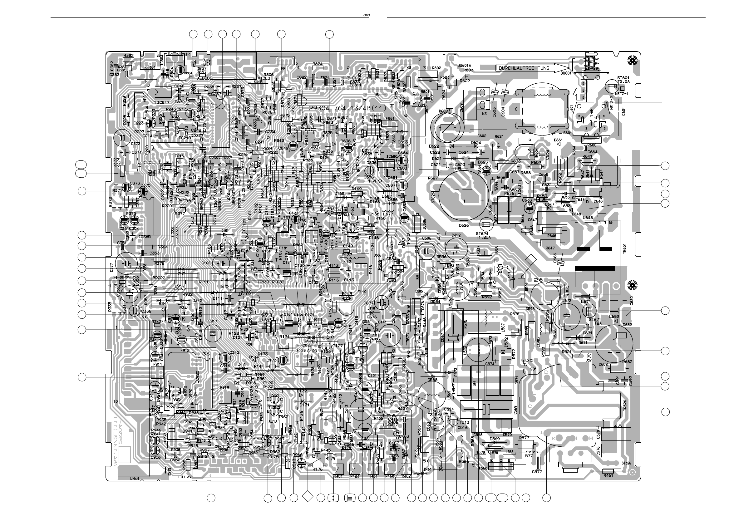
CUC 6310 CUC 6310
Chassisplatte / Chassis Board
Chassisplatte / Chassis Board
Chassisplatte / Chassis Board
45B
45A
43
4642 4448 47
41
9
~
+5V/D
14
+H
+B´
+B´´
+A/
MIN
2
3
1
4
16
12
11
17
18
19
39
357
7
1
8
1
2
B´B´
+M
+F
42
21
8
10
64
5
6
+A
+F´
20
24
1
C
D
E
+D
12
F
G
AB
35
34
33
Bestückungsseite, Ansicht von oben
Component side, top view
GRUNDIG Service
40
14
H
I
K
LM
L´
131510
21
37 2225
36 24 38B38A
27
312823
3230 2926
6GRUNDIG Service5
Page 6
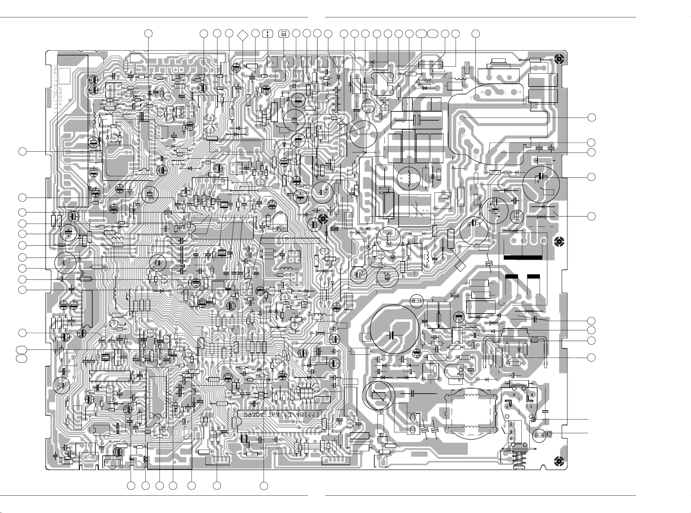
CUC 6310 CUC 6310
Chassisplatte / Chassis Board
39
40
14
131510
L´
21
372225
36 24 38B38A
27
312823
3230 2926
LM
K
I
Lötseite, Ansicht von unten
Solder side, bottom view
H
12
+D
F
E
D
G
1
C
24
+F´
6
AB
+A
33
34
35
20
19
18
17
11
12
16
8
7
43
45A
45B
+F
21
42
8
10
64
5
+M
2
1
B´
1
357
+B´´
+B´
+H
4
1
3
2
14
+5V/D
+A/
MIN
~
4642 4448 47
41
9
GRUNDIG Service
8
GRUNDIG Service7
Page 7

CUC 6310
Gesamtschaltplan / General Circuit Diagram
Platinenabbildungen und Schaltpläne / Layout of the PCBs and Circuit Diagrams
CUC 6310
Platinenabbildungen und Schaltpläne / Layout of the PCBs and Circuit Diagrams
GRUNDIG Service
109GRUNDIG Service
Page 8

CUC 6310 CUC 6310
Platinenabbildungen und Schaltpläne / Layout of the PCBs and Circuit Diagrams Platinenabbildungen und Schaltpläne / Layout of the PCBs and Circuit Diagrams
+D
ca 26V
Spannungsangaben
Voltage Levels
+A 152V
+B' 12V
+B'' 12V
+C 200V
+D ca. 26V
+F 8V
+H 5V
+M 16,5V
GRUNDIG Service GRUNDIG Service
1211
Page 9

Chassisplatte / Chassis Board
CUC 6310 Platinenabbildungen und Schaltpläne / Layout of PCBs and Circuit Diagrams
0V
500mV/cm, 2µs/cm1
100V/cm, 2µs/cm
4
0V
0V
2,3V
2V/cm, 2µs/cm
2
100V/cm, 2µs/cm
5
0V
0V
3,5V
200mV/cm, 2µs/cm
3
500mV/cm, 20µs/cm
6
0V
4,6V
7
100mV/cm, 20µs/cm
1V/cm, 20µs/cm
10
0V
0V
8
200mV/cm, 20µs/cm
100mV/cm, 1µs/cm
11
gemessen mit Signal
measured with signal
2,2V
0V
9
1V/cm, 20µs/cm
1V/cm, 10µs/cm
12
0V
0V
2V/cm, 5ms/cm
13
1V/cm, 10µs/cm
13 GRUNDIG Service
14
15
1V/cm, 10µs/cm
Page 10

0V
CUC 6310 Platinenabbildungen und Schaltpläne / Layout of PCBs and Circuit Diagrams
16
1V/cm, 20µs/cm
1V/cm, 20µs/cm
19
0V
0V
17
1V/cm, 20µs/cm
1V/cm, 20µs/cm
20
0V
0V
0V
18
1V/cm, 20µs/cm
21
1V/cm, 5ms/cm
0V
0V
0V
22
5V/cm, 5ms/cm
10V/cm, 5ms/cm
25
0V
0V
23
1V/cm, 5ms/cm
5V/cm, 5ms/cm
26
0V
0V
5V/cm, 5ms/cm
24
27
500mV/cm, 10µs/cm
0V
0V
5V/cm, 10µs/cm
28
14 GRUNDIG Service
5V/cm, 10µs/cm
29
500V/cm, 10µs/cm
30
Page 11

CUC 6310 Platinenabbildungen und Schaltpläne / Layout of PCBs and Circuit Diagrams
5V/cm, 10µs/cm
31
20V/cm, 10µs/cm
34
0V
0V
0V
50V/cm, 10µs/cm
32
50V/cm, 10µs/cm
35
0V
0V
0V
50V/cm, 10µs/cm
33
5V/cm, 10µs/cm
36
0V
0V
0V
10V/cm, 10µs/cm
37
200mV/cm, 10µs/cm
39
1V/cm, 10µs/cm
42
ohne VT-Einblendung
without VT display
0V
0V
50V/cm, 10µs/cm
38A
500mV/cm, 10µs/cm
40
500mV/cm, 10µs/cm
43
bei VT-Betrieb
on VT operation
0V
0V
50V/cm, 5ms/cm
38B
41
2V/cm, 500µs/cm
ohne VT-Einblendung
without VT display
2V/cm, 500µs/cm
44
0V
0V
0V
0V
15 GRUNDIG Service
Page 12

CUC 6310 Platinenabbildungen und Schaltpläne / Layout of PCBs and Circuit Diagrams
2V/cm, 500µs/cm
44
ohne VT-Einblendung
without VT display
2V/cm, 20µs/cm
46
bei VT-Betrieb
on VT operation
0V
0V
0V
1V/cm, 20µs/cm
45A
bei VT-Betrieb
on VT operation
2V/cm, 20µs/cm
47
Notizen / Notes
0V
0V
1V/cm, 20µs/cm
45B
bei Menü-Einblendung
on Menü display
2V/cm, 20µs/cm
48
0V
0V
16 GRUNDIG Service
Page 13

GRUNDIG Service
CUC 6310 Platinenabbildungen und Schaltpläne / Layout of PCBs and Circuit Diagrams
Bildrohrplatte / CRT Panel 29305-122.05
Servicearbeiten nach Bausteinwechsel:
siehe Abgleich Seite 3 (1-2)
Servicing work after replacing the module:
see alignment page 3 (1-2)
17
Page 14

CUC 6310Platinenabbildungen und Schaltpläne / Layout of PCBs and Circuit Diagrams
R723
C731
CX1
R771
R772
C751
C791
+12V
E
T723
B
R773
C771
R752
+
C793
+
R724
R753
R757
R751
RGB
2
+
R7XX
VB
R779
R732
R731
R733
BR10 BR12
1
BR11
R759
VG
R765
CX3
CX4
R782
1
D716
CX2
R716
R776
R777
C792
R737
R713
R722
R793A
R793
R778
R736 R738
IC790
R758
D766
D746
R738
15
142
L713
CX5
.
.
BC
R721
C786
786
D786
R747
R748
R767
R768
C766
R769
R766
R742
R762
C714
R787
R746
R749
6
5
DF1
7
29304-722.41/4B(09)
T721
C746
R789
910
8
6
4
5
4
BR2
R707
D707
R704
L708
11
12
UG2
+200V
BR
R712
..
BILDROHRPLATTE 29305-022...
2
1
C716
Lötseite, Ansicht von unten
Solder side, bottom view
1V/cm, 20µs/cm
1
1
2
0V
3
0V
1V/cm, 20µs/cm
2
BR-SOCKEL
CRT SOCKET
1V/cm, 20µs/cm
3
0V
0V
50V/cm, 20µs/cm
4
18
50V/cm, 20µs/cm
5
0V
50V/cm, 20µs/cm
6
GRUNDIG Service
0V
Page 15

T 70-740 TEXT/T 70-740/4 TOP/T 70-740 FT/GB Ersatzteilliste / Spare Parts List
GRUNDIG Service 19
ÄNDERUNGEN VORBEHALTEN SUBJECT TO ALTERATION
9 / 95 T 70-740 TEXT
T 70-740/4 TOP
T 70-740 FT/GB
Ersatzteilliste
Spare Parts List
D
Btx * 32700 #
SACH-NR. / PART NO.: 9.21426-0175 BESTELL-NR. / ORDER NO.: G.CA 3875 COSMOS-SCHWARZ/COSMOS BLACK
SACH-NR. / PART NO.: 9.21426-0275 BESTELL-NR. / ORDER NO.: G.CC 4575 COSMOS-SCHWARZ/COSMOS BLACK
SACH-NR. / PART NO.: 9.21426-6475 BESTELL-NR. / ORDER NO.: G.CC 7875 GB COSMOS-SCHWARZ/COSMOS BLACK
DESCRIPTION
POS. ABB.SACHNUMMER ANZ.
NR. NR.
POS. FIG. PART NUMBER QUA.
NO. NO.
BEZEICHNUNG
GB
0001.000 29635-161.01 GEHAEUSEVORDERTEIL KPL CABINET FRONT
0001.100 29602-603.51 GRUNDIG-EMBLEM GRUNDIG EMBLEM
0001.400 29633-513.57 ABDECKUNG KPL COVER
0007.000 29628-548.01 2 CHASSISBEFESTIGUNG CHASSIS FIXING
0009.000 19126-033.97 LAUTSPRECHER LOUDSPEAKER
0010.000 29618-015.14 AUFKLEBER TYPE .01 ADHESIVE LABEL;STICKER .01
0010.000 29618-016.14 AUFKLEBER TYPE .02 ADHESIVE LABEL;STICKER .02
0010.000 29617-503.14 AUFKLEBER TYPE .64 ADHESIVE LABEL;STICKER .64
0011.000 29631-726.80 GEHAEUSERUECKTEIL .01 REAR PANEL .01
0011.000 29631-726.85 GEHAEUSERUECKTEIL .02/.64 REAR PANEL .02/.64
29656-003.65 MONTAGE-ZUBEHOER F. BILDROHR MOUNTING ACCESSORIES FOR CRT
KEIN E-TEIL NO SPARE PART
0021.000 29607-219.01 8 SPULENHAKEN COIL HOOK
0024.000 09246-191.75 ENTMAGNETISIERUNGSSPULE DEGAUSING COIL
0025.000 8300-030-435 BILDR.A 66 EAK 71X01 WW. CRT A 66 EAK 71X01 OPT
0026.000 29201-360.02 ANODENKAPPE M. HOCHSPG.-KABEL C.R.T. SOCKET
0045.000 29501-082.22 BEDIENEINHEIT CONTROL UNIT
0045.100 29501-622.01 TASTENSATZ KEYS SET
0045.200 29303-390.43 KOPFHOERERBUCHSE HEADPHONE SOCKET
0045.300 29303-168.06 CINCHBUCHSE 2-FACH CINCH SOCKET 2 FOLD
0049.000 29501-658.01 VERLAENGERUNG F.NETZTASTE EXTENSION FOR POWER KEY
0050.000 29628-795.01 2 CLIP F.CHASSISBEF. CLIP
0052.000 8290-991-316 NETZKABEL KPL. .01/.02 POWER CABLE CPL GWN9.22 .01/.02
0052.000 8290-991-386 NETZKABEL KPL. .64 POWER CABLE CPL GWN9.22 .64
0053.000 29642-059.06 TELEPILOT TP 720 REMOTE CONTROL TP 720
29305-122.05 X BILDROHRPLATTE BM PICTURE TUBE BOARD
21426-941.01 BEDIENUNGSANLEITUNG .01 INSTRUCTION MANUAL .01
21426-941.02 BEDIENUNGSANLEITUNG .02 INSTRUCTION MANUAL .02
21426-941.03 BEDIENUNGSANLEITUNG .64 INSTRUCTION MANUAL .64
72010-013.81 SERVICE MANUAL SERVICE MANUAL
72010-013.80 SERVICE MANUAL SERVICE MANUAL
29701-084.03 X COLOR-EINBAUCHASSIS .01 COLOR TV CHASSIS .01
CUC 6310 CUC 6310
KEIN E-TEIL NO SPARE PART
29701-084.07 X COLOR-EINBAUCHASSIS .02 COLOR TV CHASSIS .02
CUC 6310 CUC 6310
KEIN E-TEIL NO SPARE PART
29701-084.08 X COLOR-EINBAUCHASSIS .64 COLOR TV CHASSIS .64
CUC 6310 CUC 6310
KEIN E-TEIL NO SPARE PART
X = SIEHE GESONDERTE E-LISTE X = SEE SEPARATE PARTS LIST
D
Page 16

Ersatzteilliste / Spare Parts List T 70-740 TEXT/T 70-740/4 TOP/T 70-740 FT/GB
POS.
NR.
POS.
NO.
D 816 8309-944-601 LE DIODE TLHR 4601 TFK
IC84001 8305-367-530 IC TFMS 5300
SACHNUMMER
PART NUMBER
BEZEICHNUNG
DESCRIPTION
GB
D
POS.
NR.
POS.
NO.
SACHNUMMER
PART NUMBER
BEZEICHNUNG
DESCRIPTION
D
GB
1
1.1
29635-161.01
29602-603.51
Es gelten die Vorschriften und Sicherheitshinweise gemäß dem Service Manual "Sicherheit",
Sach-Nummer 72010-800.00, sowie zusätzlich
die eventuell abweichenden, landesspezifischen
( )
The regulations and safety instructions shall be
valid as provided by the "Safety" Service Manual,
part number 72010-800.00, as well as the
respective national deviations.
Vorschriften!
ÄNDERUNGEN VORBEHALTEN SUBJECT TO ALTERATION
20 GRUNDIG Service
Page 17

29701-084.03/.07/.08 Ersatzteilliste / Spare Parts List
GB
D
D
Ersatzteilliste
Spare Parts List
9 / 93 CUC 6310 MONO
SACH-NR. / PART NO.: 29701-084.03/.07/.08
POS. ABB.SACHNUMMER ANZ.
NR. NR.
POS. FIG. PART NUMBER QUA.
NO. NO.
0001.000 29504-201.01 CHIP-TUNER/HYPERBAND SMD TUNER/HYPERBAND
0002.000 29303-119.06 PERIBUCHSE SCHWARZ PERI SOCKET BLACK
0004.000 29500-513.01 ABDECKUNG EURO-AV COVER EURO-AV
0005.000 29700-435.01 ABDECKUNG NETZ COVER
0006.000
WW.
0007.000
0011.000 29303-153.12 MONTAGECLIP T644/IC676/686 ASSEMBLY CLIP
0012.000 29303-153.02 MONTAGECLIP T568/IC430 ASSEMBLY CLIP
0013.000 29303-156.20 WAERMELEITFOLIE T644/IC676 HEAT CONDUCTING FOIL
0014.000 29303-156.03 GLIMMERSCHEIBE T568 MICA LAMINATION
0015.000 29303-156.06 ISOLIERSCHEIBE IC676 INSULATING WASHER
29703-291.22 NETZSCHALTER POWER SWITCH
29703-291.32 NETZSCHALTER POWER SWITCH
29303-399.91 GERAETESTECKER M.KABEL APPLIANCE PLUG
BEZEICHNUNG
D
DESCRIPTION
WW. = WAHLWEISE WW. = OPTIONAL
POS.
NR.
POS.
NO.
C 125 8668-203-023 ABBLOCK-C 0,1 UF -GR
C 237 8555-267-233 KT/MKT 5/3-4 2200PF 5%
C 241 8668-203-023 ABBLOCK-C 0,1 UF -GR
C 242 8668-203-023 ABBLOCK-C 0,1 UF -GR
C 245 8668-203-023 ABBLOCK-C 0,1 UF -GR
C 246 8668-203-023 ABBLOCK-C 0,1 UF -GR
C 382 8668-203-023 ABBLOCK-C 0,1 UF -GR
C 411 8605-767-058 SSPN 390PF 20% 400V -GR
C 421 8531-573-024 MKT 15 0,22 UF 20% 250V
C 566 8555-267-125 KT/MKT 5/3-4 1000PF 20%
C 567 8515-721-240 KF 31 0,36 UF 5% 250V
C 568 8515-911-424 KF 38 0,027 UF 5% 400V
C 569 8515-911-114 KF 35 9000PF 3,5% 1600V
C 573 8515-722-221 MKP 10 0,21 UF 5% 160V/
C 574 8515-722-242 MKP 4 0,33 UF 5% 160V/MKP
C 576 8525-040-819 KF 24 0,33 UF 10% 250V
C 577 8558-567-255 KP E 0,018UF 10% 63V
C 578 8525-040-819 KF 24 0,33 UF 10% 250V
C 596 8426-098-061 ELKO CB 4,7UF 350V
C 598 8452-027-335 ELKO 29/V 22UF 350V
C 601
C 602
C 603
C 604
C 609 8563-732-425 KF 25 0,1 UF 20% 250VW
C 621 8650-081-125 HV-KERKO 1000PF 20% 1KV
C 622 8650-081-125 HV-KERKO 1000PF 20% 1KV
SACHNUMMER
PART NUMBER
8511-793-020 MP 3 0,1 UF 20% 250VW RM
8511-793-020 MP 3 0,1 UF 20% 250VW RM
8660-098-234 SI-KERKO B-SS 1000PF 20%
8660-098-234 SI-KERKO B-SS 1000PF 20%
BEZEICHNUNG
DESCRIPTION
GB
POS.
NR.
POS.
NO.
C 623 8650-081-125 HV-KERKO 1000PF 20% 1KV
C 624 8650-081-125 HV-KERKO 1000PF 20% 1KV
C 626 8451-997-119 ELKO 22 220UF 385V
C 632 8555-269-033 KT/MKT 5/6 2200PF 5%
C 646 8650-067-486 HV-KERKO 470PF 20% 2KV
C 648 8515-911-605 FKP1 220PF 5% 2000V
C 664 8555-269-041 KT/MKT 5/6 4700PF 5%
C 666
C 671 8650-067-046 HV-KERKO 100PF 20% 1KV
C 838 8682-365-336 KDPU 5 -GR 0,047UF +80C 862 8668-203-023 ABBLOCK-C 0,1 UF -GR
C 863 8682-365-336 KDPU 5 -GR 0,047UF +80C 865 8668-203-023 ABBLOCK-C 0,1 UF -GR
C 912 8555-367-541 KT/MKT 5 4700PF 10%
D 101 8309-720-091 Z DIODE 9,1 C 0,5W
D 131 8309-198-040 DIODE BAT 41 (TYP 4)
D 132 8309-215-045 DIODE 1 N 4148 ITT/TID
D 142 8309-200-021 DIODE BAV 21 ITT
D 146 8309-215-045 DIODE 1 N 4148 ITT/TID
D 147 8309-215-045 DIODE 1 N 4148 ITT/TID
D 148 8309-215-045 DIODE 1 N 4148 ITT/TID
D 161 8309-215-045 DIODE 1 N 4148 ITT/TID
D 168 8309-215-045 DIODE 1 N 4148 ITT/TID
D 233 8309-510-530 KAP.DIODE BB 531 -GA
D 243 8309-214-010 DIODE TD 129 -GA
D 338 8305-306-001 IC ZTK 33 B DPD ITT
SACHNUMMER
PART NUMBER
8660-098-238 SI-KERKO B-SS 2200PF 20%
BEZEICHNUNG
DESCRIPTION
GB
ÄNDERUNGEN VORBEHALTEN ALTERATIONS RESERVED
GRUNDIG Service 21
Page 18

Ersatzteilliste / Spare Parts List 29701-084.03/.07/.08
POS.
NR.
POS.
NO.
D 342 8309-215-045 DIODE 1 N 4148 ITT/TID
D 356 8309-215-006 DIODE 1 N 4001 -GA
D 358 8309-720-027 Z DIODE 2,7 C 0,5W
D 411 8309-210-138 DIODE 1N4936 DIO/FAG/ITT/
D 416 8309-210-138 DIODE 1N4936 DIO/FAG/ITT/
D 418 8309-720-048 Z DIODE 4,7 C 0,5W
D 461 8309-720-221 Z DIODE 22 B 0,5W
D 462 8309-215-045 DIODE 1 N 4148 ITT/TID
D 513 8309-214-010 DIODE TD 129 -GA
D 521 8309-720-048 Z DIODE 4,7 C 0,5W
D 566 8309-720-331 Z DIODE 30 C 0,5W
D 568 8309-210-144 DIODE BYW 76 TFK .03/BYW
D 569 8309-204-228 DIODE BY 228 PHI/GI/TFK
D 572 8309-201-005 DIODE BA 157
D 584 8309-200-021 DIODE BAV 21 ITT
D 585 8309-720-221 Z DIODE 22 B 0,5W
D 586 8309-720-112 Z DIODE 12 C 0,5W
D 587 8309-214-010 DIODE TD 129 -GA
D 592 8309-200-021 DIODE BAV 21 ITT
D 596 8309-215-020 DIODE 1 N 4004 -GA
D 598 8309-204-268 DIODE BYV 16 TFK/BYV 96E/
D 621 8309-215-127 DIODE 1 N 4007 -GA
D 622 8309-215-127 DIODE 1 N 4007 -GA
D 623 8309-215-127 DIODE 1 N 4007 -GA
D 624 8309-215-127 DIODE 1 N 4007 -GA
D 641 8309-518-023 DIODE BYS 21-45 SIE
D 647 8309-516-854 DIODE BYT 54 M/SK 09 D10
D 648 8309-516-854 DIODE BYT 54 M/SK 09 D10
D 653 8309-516-754 DIODE BYT 53 B/SK1 G F01
D 661 8309-516-754 DIODE BYT 53 B/SK1 G F01
D 671 8309-517-172 DIODE BYW 172 D/SK 3 G F0
D 672 8309-215-006 DIODE 1 N 4001 -GA
D 682 8309-517-178 DIODE BYW 178/SK 3 G D08
D 814 8309-215-045 DIODE 1 N 4148 ITT/TID
D 834 8309-214-010 DIODE TD 129 -GA
D 836 8309-214-010 DIODE TD 129 -GA
D 838 8309-214-010 DIODE TD 129 -GA
D 912 8309-215-045 DIODE 1 N 4148 ITT/TID
D 918 8309-215-045 DIODE 1 N 4148 ITT/TID
F 110 29303-117.04 VERZOEGERUNGSLEITUNG
F 118 8140-835-211 SPULE 7X7 211
WW. 8140-535-211 SPULE 7X7 211
F 120 8140-601-600 FILTER SFB 4595 TDK
F 213 8140-540-222 EMIFIL 2200 PF
F 821 8602-331-085 CER.RES.85 4,00 MG
F 861 8140-540-104 EMIFIL 0,1 UF
F 911 8140-833-605 SPULE 7X7 605
WW. 8140-533-605 SPULE 7X7 605
F 912 8319-001-956 OFW G 1962 SIE/SCF 114
F 919 8141-811-603 FILTER 7X7 603 FARBE 657
WW. 8141-111-603 FILTER 7X7 603 FARBE 657
F 934 8602-755-021 CER.TRAP 21 TPS 5,5 MB
F 935 8141-812-405 FILTER 7X7 405
WW. 8141-112-405 FILTER 7X7 405
F 937 19203-065.97 KERAMIK-FILTER 40
IC 130 8305-125-102 IC STV 2102 SGS
IC 210 8305-972-306 IC CF 72306 TID
IC 270 8305-970-095 IC CF 70095 ANF TI
IC 365 8305-367-245 IC TDA 7245 A SGS
IC 430 8305-338-174 IC TDA 8174 W
IC 440 8305-338-145 IC TDA 8145
IC 631 8305-354-605 IC TDA 4605/3
IC 676 8305-204-317 IC LM 317 T NSC/MOT/
IC 680 8305-205-705 IC MC 78 M 05 CT MOT
IC 686 8305-205-703 IC MC 7805 CT
IC 811 8305-684-655 IC ZC 88655 P
SACHNUMMER
PART NUMBER
BEZEICHNUNG
DESCRIPTION
D
GB
POS.
NR.
POS.
NO.
IC 820 8305-210-064 IC MC 33164 P-5RP
IC 847 8305-602-405 IC X 24 C 04 XICOR/ST 24
IC 920 8305-335-940 IC TDA 5940
L 113 8140-526-014 DR AX 0309-GA 6,8 UH 10%
L 181 8140-512-933 DR LI 0207-GR 4,7 UH 5%
L 182 8140-512-931 DR LI 0207-GR 3,9 UH 5%
L 232 8140-526-947 DR N-GR 1,5UH
L 270 8104-982-014 DAEMPFUNGSPERLE
L 336 8140-505-247 DR A AX-GA 8,2UH
L 337 8140-505-075 DR A AX-GA 120UH
L 567 09246-846.21 BRUECKENSPULE 110" 1,5 MH
L 568 8104-982-056 FERRITPERLE HF 70 BTL
L 570 8104-982-056 FERRITPERLE HF 70 BTL
L 573 29203-110.97 LINEARITAETSREGLER
L 577 8140-526-310 DR AX 0411-GA 10UH
L 601
L 648 8104-982-057 FERRITPERLE-GA 3,6UH
L 653 8104-982-058 FERRITPERLE-GA 1,7UH
L 671 8104-982-014 DAEMPFUNGSPERLE
L 677 8140-525-969 DR AX 0411-GA 22UH
L 682 8104-982-057 FERRITPERLE-GA 3,6UH
L 687 8104-982-014 DAEMPFUNGSPERLE
L 912 8140-526-451 DR AX 0411-GA 8,2UH
L 917 8140-525-998 DR AX 0411-GA 15UH
L 954 8104-982-014 DAEMPFUNGSPERLE
Q 161 8602-099-503 CER.SCHWINGER CSB 503 F12
Q 171 8382-121-044 QUARZ 4,433619 MHZ
Q 212 8382-501-138 QUARZ 13,875 MHZ 20PF
R 102
R 119 8790-050-017 ESTR.SK10-A 220 OHM LIN
R 178 8790-250-050 ESTR.PPK10-A 10 KOHM LIN
R 337 8705-370-134 MOW LI 0922 15 KOHM 5%
R 376
R 401 8792-001-164 ESTR.P6/A 100 KOHM LIN
R 412
R 421
R 423 8792-001-135 ESTR.P6/A 1 KOHM LIN
R 431 8792-001-167 ESTR.P6/A 220 KOHM LIN
R 437
R 441
R 448 8773-297-040 ESTR.P 2,2 KOHM LIN PHI
R 462 8792-001-135 ESTR.P6/A 1 KOHM LIN
R 468 8792-001-164 ESTR.P6/A 100 KOHM LIN
R 563 8705-329-033 MOW LI 0411 27 OHM 5%
R 566 8705-328-993 MOW LI 0411 0,51 OHM 10%
R 569
R 573 8705-221-271 MOW AX 0411 820 OHM 10%
R 577 8705-329-221 MOW LI 0411 6,8 OHM 10%
R 578 8710-338-145 MGW AX 1 MOHM 5% VR 37
R 586
R 598 8705-221-225 MOW AX 0411-GA 10 OHM
R 599 8705-227-021 MOW AX 0411-GA 6,8 OHM
R 600
R 609
R 623 8311-400-125 VDR SD/1 250V -GR
R 624
R 627
R 646 8705-369-301 MOW LI 0617 15 KOHM 10%
R 647 8705-369-301 MOW LI 0617 15 KOHM 10%
R 654 8790-050-037 ESTR.SK10-A 1,5 KOHM LIN
R 682 8705-329-321 MOW LI 0411 100 KOHM 10%
SACHNUMMER
PART NUMBER
29500-812.97 FUNKENTSTOERDROSSEL
8701-118-021 KSW SI B 6,8 OHM 5% -GA
8701-118-017 KSW SI B 4,7 OHM 5% -GA
8700-252-017 KSW AX 0414 NE 4,7 OHM
8700-229-009 KSW AX 0207-GA NB
8700-229-049 KSW AX 0207-GA NB
8700-202-007 KSW AX 0207-GA NB
8701-230-817 NKS 3 4,7 OHM 5% ROE
8700-329-083 KSW LI 0207-NB 2,7 KOHM
8765-049-157 MSW AX 0414-GA 3,3 MOHM
8311-200-010 DUO-PTC
8766-349-161 MSW LI 0414 4,7 MOHM
8766-349-161 MSW LI 0414 4,7 MOHM
BEZEICHNUNG
DESCRIPTION
D
GB
ÄNDERUNGEN VORBEHALTEN ALTERATIONS RESERVED
22 GRUNDIG Service
Page 19

29701-084.03/.07/.08 Ersatzteilliste / Spare Parts List
POS.
NR.
POS.
NO.
SI 563 8315-612-027 LOET-SI.-GR 315 MA/T
SI 601
SI 624
SI 671
T 101 8303-269-338 TRANS.BC 338
T 103 8303-207-548 TRANS.BC 548 C
T 127 8303-207-548 TRANS.BC 548 C
T 139 8303-205-548 TRANS.BC 548 B
T 147 8303-201-558 TRANS.BC 558
T 163 8303-201-558 TRANS.BC 558
T 168 8303-201-548 TRANS.BC 548
T 262 8303-205-548 TRANS.BC 548 B
T 267 8303-205-548 TRANS.BC 548 B
T 272 8303-205-548 TRANS.BC 548 B
T 277 8303-205-548 TRANS.BC 548 B
T 513 8303-285-637 TRANS.BC 637
T 568 8302-260-506 TRANS.BU 508 A PHI/SANYO/
T 583 8303-205-548 TRANS.BC 548 B
T 593 8303-401-299 TRANS.S 298 T TFK/PBF 259
T 644 8302-269-089 TRANS.BUZ 90
T 801 8303-207-548 TRANS.BC 548 C
T 835 8303-205-548 TRANS.BC 548 B
T 936 8303-201-548 TRANS.BC 548
T 961 8303-201-558 TRANS.BC 558
T 962 8303-201-548 TRANS.BC 548
SACHNUMMER
PART NUMBER
8315-621-027 LOET-SI.-GR 2,5 A/T
8315-618-225 LOET-SI.-GR 1,25 A/T
8315-620-225 LOET-SI.-GR 2 A/T
BEZEICHNUNG
DESCRIPTION
D
GB
POS.
NR.
POS.
NO.
SACHNUMMER
PART NUMBER
BEZEICHNUNG
DESCRIPTION
D
GB
TR 526
TR 563
TR 651
WW.
29201-029.51 DIODEN-SPLIT TRAFO KPL
09246-863.04 TREIBERTRAFO
29201-455.02 SPERRWANDLERTRAFO KPL
29201-502.97 SPERRWANDLERTRAFO KPL
ÄNDERUNGEN VORBEHALTEN ALTERATIONS RESERVED
GRUNDIG Service 23
Page 20

GRUNDIG Service
GRUNDIG
Marketing und Vertrieb Europa GmbH
Kundendienst
Deutschland
GRUNDIG
Vertriebs-GmbH
Kundendienst West
Horbeller Str. 19
Köln
50858
0 22 34/95 81-251
GRUNDIG
Vertriebs-GmbH
Kundendienst Mitte
Dudenstr. 45-53
Mannheim
68167
06 21/33 76-70
22113
13509
04430
90471
GRUNDIG
Vertriebs-GmbH
Kundendienst Nord
Kolumbusstr. 14
Hamburg
0 40/7 33 31-0
GRUNDIG
Vertriebs-GmbH
Kundendienst Berlin
Wittestr. 30e
Berlin
0 30/4 38 03-21
GRUNDIG
Vertriebs-GmbH
Kundendienst Leipzig
Leipziger Str. 198
Böhlitz-Ehrenberg
03 41/44 82-3
GRUNDIG
Vertriebs-GmbH
Kundendienst Süd
Beuthener Str. 65
Nürnberg
09 11/7 03-0
GRUNDIG
Marketing und Vertrieb Europa GmbH
Kundendienst
Europa
GRUNDIG BELUX N.V.
Deltapark Unit 3, Weihoek 3
Zaventem
B-1930
00 32-2-7 16 04 00
GRUNDIG INTERNATIONAL LTD.
Millroad, Rugby Warwickshire, CV21 1PR
Großbritannien/Great Britain
GB
00 44-1-7 88-57 71 55
GRUNDIG IRELAND LTD.
Unit 9, Western Industrial Estate, Naas Road
Dublin 12
EIR
0 03 53-1-4 50 93 66
GRUNDIG FRANCE S.A.
33-35 Boulevard de la Paix
Saint Germain-en-Laye
F-78104
00 33-1-30 61 30 00
GRUNDIG SCHWEIZ AG
Steinacker Str. 28
Kloten
CH-8302
00 41-1-8 15 81 11
GRUNDIG Ibérica
Centro de Servicos Lda.
Rua Bento de Jesus Caraca 17
Lisboa, Cruz Quebrada
P-1495
0 03 51-1-4 19 75 70
GRUNDIG NORGE A. S.
Glynitveien 25, Postboks 234
Ski
N-1401
00 47-64 87 82 00
GRUNDIG OY
Luoteisrinne 5
Espoo
SF-02271
0 03 58-0-8 04 39 00
GRUNDIG DANMARK A/S
Lejrvej 19
Værløse
DK-3500
00 45-42 48 68 22
GRUNDIG SVENSKA AB
Albygatan 109 d, Box 4050
Solna
S-17104
00 46-8-6 29 85 30
GRUNDIG AUSTRIA Ges.m.b.H.
Breitenfurter Straße 43-45
Wien
A-1120
00 43-1-8 11 17 0
GRUNDIG NEDERLAND B. V.
Gebouw Amstelveste
Joan Muyskenweg 22
CJ Amsterdam
NL-1096
00 31-20-5 68 15 68
GRUNDIG ESPAÑA S.A.
Solsonés S/N°, B3
Edificio Muntadas (Mas Blau 1)
El Prat De Llobregat (Barcelona)
E-08820
00 34-3-4 79 92 00
Änderungen vorbehalten Printed in Germany Service Manual Sach-Nr.
Subject to alteration VK 24 0296 Service Manual Part No. 72010-013.81
GRUNDIG ITALIANA S.P.A.
Via Brennero 364
Trento
I-38100
00 39-461 82 20 55
 Loading...