

Page 1
1 SERVICE MANUAL
Ergänzung
Supplement
1
Sach-Nr./Part No.
72010-014.81
Zusätzlich erforderliche Unterlagen
für den
Komplettservice:
Additionally
required Service
Manuals for the
Complete Service:
Service
Manual
CUC 6301
Sach-Nr./Part No.
72010-014.80
Service
Manual
Sach-Nr./Part No.
D
Für diese Geräte gilt das Service Manual CUC 6301.
Dieses Manual beinhaltet die Unterschiede bzw. zusätzlichen Bestükkungen der Geräte.
Die Bausteinbestückung und die Sachnummern der einzelnen Bausteine entnehmen Sie bitte der Tabelle Seite 3.
Grundlage für den Service sind:
– Sicherheitsvorschriften (Sach-Nr. 72010-800.00)
– Service Manual CUC 6301 (Sach-Nr. 72010-014.80)
Sicherheit
Safety
72010-800.00
CUC 6301
T 55-64/4 ASIS (9.21266-01 / GCA 0652)
P 45-64/4 ASIS (9.21265-01 / GCA 0752)
P 40-64/4 ASIS (9.21264-01 / GCA 0852)
GB
For these TV sets the Service Manual CUC 6301 is applicable.
This Manual contains the differences and the additionally fitted modules of the TV receivers.
The individual modules and the relevant part numbers are listed in the
table on page 3.
Basic instructions for servicing are given in the:
– Safety Instructions (Part No. 72010-800.00)
– Service Manual CUC 6360 / 6365 (Part No. 72010-014.80)
Hinweis:
Die ASIS-Fernsehgeräte sind durch Überbrücken des Netzschalters
in Dauer-Standby geschaltet. Ohne ASIS-Steckkarte können Sie
das Gerät wie ein normales Fernsehgerät betreiben und prüfen.
ASIS spezifische Informationen erhalten nur autorisierte ASISServicestellen.
Die für Sie zuständige ASIS-Servicestelle entnehmen Sie bitte
dem Abnahmeprotokoll.
Änderungen vorbehalten Printed in Germany Service Manual Sach-Nr. 72010-014.81
Subject to alteration VK 221 0395 Service Manual Part No. 72010-014.81
Note:
ASIS television receivers are continously switched to standby by
bridging the mains switch. Without the ASIS plug-in board, the
television receivers can be operated and checked like any other
television receiver.
Specific ASIS specifications are only given to authorized ASIS
workshops.
For your competent ASIS workshop, please see the acceptance
report.
Page 2

Allgemeiner Teil / General Section CUC 6301 ASIS
Es gelten die Vorschriften und Sicherheitshinweise gemäß dem Service Manual "Sicherheit",
Sach-Nummer 72010-800.00, sowie zusätzlich
die eventuell abweichenden, landesspezifischen
Vorschriften!
D
Inhaltsverzeichnis
Seite
Allgemeiner Teil.......................................... 1…3
Technische Daten .......................................................................... .3
Modulübersicht................................................................................ 3
Beschreibungen........................................... 4…6
ASIS System ................................................................................... 4
Schaltpläne ................................................ 7…12
Gesamtschaltplan ........................................................................... 7
ZF-Verstärker 29504-102.31......................................................... 11
The regulations and safety instructions shall be
valid as provided by the "Safety" Service Manual,
part number 72010-800.00, as well as the
respective national deviations.
GB
Table of Contents
Page
General Section ............................................ 1...3
Technical Data ................................................................................ 3
Module List...................................................................................... 3
Descriptions................................................. 4…6
ASIS System ................................................................................... 4
Circuit Diagrams ...................................... 7…12
General Circuit Diagram ................................................................. 7
IF Amplifier 29504-102.31............................................................. 11
Ersatzteilliste........................................... 13…21
Allgemeiner Teil
Meßgeräte / Meßmittel
Regeltrenntrafo Meß-/Wobbelsender
Farbgenerator Oszilloskop
DC-Voltmeter NF-Voltmeter
NF-Generator Frequenzzähler
Beachten Sie bitte das Grundig Meßtechnik-Programm, das Sie unter
folgender Adresse erhalten:
Spare Parts List ...................................... 13…21
General Part
Test Equipment / Aids
Variable isolating transformer Test/Sweep generator
Colour generator Oscilloscope
DC Voltmeter AF Voltmeter
AF Generator Frequency counter
Please note the Grundig Catalog "Test and Measuring Equipment"
obtainable from:
Grundig electronics GmbH
Würzburger Str. 150
D-90766 Fürth/Bay.
Tel.0911/703-0
Telefax 0911/703-4479
Grundig electronics GmbH
Würzburger Str. 150
D-90766 Fürth/Bay.
Tel.0911/703-0
Telefax 0911/703-4479
GRUNDIG Service2
Page 3
CUC 6301 ASIS Allgemeiner Teil / General Section
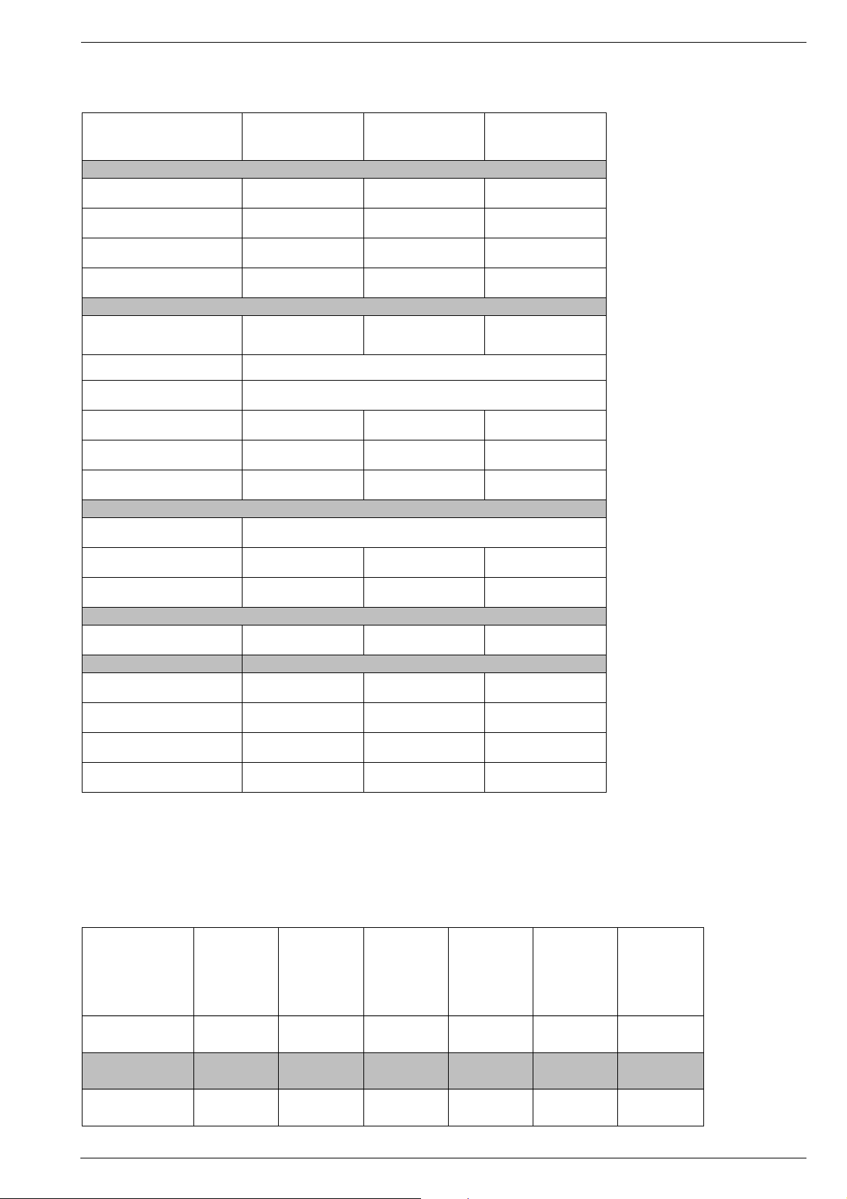
Technische Daten / Technical Data
T 55-64/4 ASIS P 45-64/4 ASIS P 40-64/4 ASIS
Bildröhre / Picture Tube
Sichtbares Bild
Visible picture
Bildschirmdiagonale
Screen diagonale
Ablenkwinkel
Deflection angle
Bildwechselfrequenz
Vertical frequency
Elektronik / Electronic
Programmspeicherplätze
Programme positions
AV-Auswertung
AV evaluation
Tuner Kabeltuner-Raster 8MHz für Hyperband / cable tuner - 8MHz spacing for hyperband
TV-Normen
TV standards
Videotext
Teletext
Musikleistung
Music power
Anschlüsse Front / Connections front
Kopfhörer
Headphones
Video IN 1x Cinch 1x Cinch 1x Cinch
51cm 41cm 36cm
55cm (21")
Black Matrix
90° 90° 90°
50Hz 50Hz 50Hz
49 TV + 1 AV 49 TV + 1 AV 49 TV + 1 AV
auf jeden Programmplatz programmierbar / programmable for every programme position
PAL/SECAM
B, G, I, D, K
auf ASIS-Karte
at ASIS Board
2x 4W 2x 4W 2x 4W
Stereo 3,5mm Klinken-Schaltbuchse / Stereo 3.5mm jack switch socket
45cm (17")
FST tinted glass
PAL/SECAM
B, G, I, D, K
auf ASIS-Karte
at ASIS Board
40cm (15")
Black Planar
PAL/SECAM
B, G, I, D, K
auf ASIS-Karte
at ASIS Board
Audio IN 1x Cinch 1x Cinch 1x Cinch
Anschlüsse Rückwand / Connections rear panel
Euro AV (schwarz/black)
Netzteil / Mains Stage
Netzspannung (Regelbereich)
Mains voltage (variable)
Netzfrequenz
Mains frequency
Leistungsaufnahme
Power consumption
Standby ca. 9W ca. 8W ca. 9W
voll belegt
fully wired
190 …264V 165 …265V 165 …265V
50 / 60Hz 50 / 60Hz 50 / 60Hz
ca. 60W ca. 85W ca. 55W
voll belegt
fully wired
voll belegt
fully wired
Modulübersicht / Module List
Gerät
Unit
Chassis Tuner
ZF-Verstärker
IF Amplifier
BR-Platte
CRT Panel
Bedieneinheit
Control Unit
ASIS-Baustein
ASIS Module
T 55-64/4 ASIS 29701-090.53 29504-201.04 29504-102.31 29305-022.07 29501-080.66 29504-108.18
P 45-64/4 ASIS 29701-090.52 29504-201.04 29504-102.31 29305-022.07 29501-080.68 29504-108.18
P 40-64/4 ASIS 29701-090.51 29504-201.04 29504-102.31 29305-022.07 29501-080.68 29504-108.18
GRUNDIG Service 3
Page 4

Schaltungsbeschreibung / Circuit Description CUC 5302 ASIS
ASIS System
ASIS = Adressierbares Sicherheits und Informations-System
Systembeschreibung
Das ASIS-System besteht aus einem PC, der über die Antennenleitung mit den angeschlossenen Geräten kommuniziert.
ASIS ermöglicht verschiedene Benutzungsmöglichkeiten:
Vollständige Fernsteuerbarkeit der angeschlossenen Fernseher.
- Die Kanalbelegung wird von der Zentrale aus durchgeführt.
- Die maximal mögliche Lautstärke kann von der Zentrale aus vorgegeben werden.
- Die Lautstärke kann von der Zentrale selektiv verändert werden.
- Die Kanalbelegung erfolgt selektiv.
Informationsmedium. Zentrale –> Gast und umgekehrt.
- Alarmierung im Katastrophenfall und Übersicht der Fluchtwege am
Bildschirm.
- Rauchmelder können an das Fernsehgerät angeschlossen werden
und geben über ASIS der Zentrale Alarm unter Angabe der Zimmernummer.
- allgemeine Hotel Informationen (Hoteleigene Videotext-Seiten)
- allgemeine und seleketive Nachrichten für den Gast
- Bestellservice
- Weckdienst
- Konferenzkanäle können eröffnet und die Fernsehgeräte eingeschaltet werden.
- Das TV-Gerät kann auch als Radio mit dunkelgetastetem Bild
verwendet werden.
Diebstahlschutz
- Sobald das Gerät vom Netz oder der Antenne getrennt wird,
bekommt die Zentrale eine Alarmmeldung.
ASIS System
ASIS = Addressable Security and Information System
System Description
The ASIS System consists of a PC which communicates with the
connected TV receivers via the aerial cable.
ASIS offers various possibilities of applications:
Complete remote-controllability of the connected TV receivers.
- The channels are selected by the central office.
- The maximum possible volume level is determined by the central
office.
- The central office can change the volume level selectively.
- The channels are programmed selectively.
Information medium. Central office –> guest and vice versa.
- To give the emergency alert and to display a diagram of the escape
routes on the screen.
- It is possible to connect smoke alarm systems to the TV receivers to
alarm the central office via the ASIS system with indication of the
number of the hotel room.
- general hotel information (the hotel's own videotext pages).
- general and selective information for the guests.
- room service
- wake-up service
- conference channels can be opened and the TV receivers switched
on.
- The TV receiver can also be used as a radio with blanked picture.
Protection against theft
- As soon as the TV receiver is disconnected from the mains or the
aerial the central office receives an alarm signal.
Datenverkehr zwischen der ASIS-Zentrale und dem Fernseher
Der Datenverkehr findet bidirektional über die Antennenleitung statt.
Die Daten von der ASIS-Zentrale zum Fernseher laufen mit 46,7MHz
zu den Geräten. Der Rückkanal arbeitet mit 13MHz. Dort wird eine
Aufsplittung zwischen dem ASIS-Modem und dem Fernseher vorgenommen.
Die 46,7MHz werden direkt aus dem Tunereingang entnommen, die
13MHz des Rückkanals werden an gleicher Stelle wieder eingespeist.
Das Modem
Die für den ASIS-Prozessor bestimmten Daten werden vom Modem
aus dem 46,7MHz Signal gewonnen und dem Prozessor über "DATA IN“
mitgeteilt.
Für den Rückweg schickt der Prozessor Daten über "DATA OUT“ ans
Modem, welches über "Daten senden“, die Daten aufmoduliert und
abschickt.
IR-Fernsteuerbefehle
Die vom Infrarot-Empfänger kommenden IR-Fernsteuersignale gehen
exklusiv zur ASIS-Karte. Dort holt sich der Prozessor die für ihn
bestimmten Befehle und unterschlägt andere Befehle. Diesen verringerten "zensierten“ IR-Datenstrom schickt die ASIS-Karte weiter an
den Fernseh-Prozessor. So wird es möglich, Funktionen zu sperren
und die Kontrolle über den Fenseher zu haben, ohne den Fernsehprozessor oder dessen Programm zu ändern.
Ändern der Daten im Fernseh-EEPROM
Die ASIS-Karte bekommt vom PC den Befehl, die Programmbelegung
oder andere Fernsehdaten zu ändern. Dafür braucht der ASIS-Prozessor Zugriff auf das EEPROM des Fernsehers. Da in einem I2CBussystem aber nur ein Master existieren darf, schickt der ASISProzessor kurzerhand einen Reset an den Fernsehprozessor. Solange der Reset anliegt, ist der eigentliche Master abgeschaltet und der
ASIS-Prozessor kann gefahrlos auf den I2C-Bus zugreifen.
Der ASIS-Prozessor vergleicht die gewünschten Daten mit den bereits
im EEPROM vorhandenen Daten. Sind Abweichungen festzustellen,
so schreibt er die neuen Daten ins Fernseh-EEPROM. Nach vollzogener Manipulation gibt er den Fernseher durch Wegnahme des Resets
wieder frei. Der Fernseher geht in Bereitschaft wie nach einem
Netzausfall. Ab jetzt ist die ASIS-Karte wieder nur passiver Zuhörer auf
dem I2C-Bus.
Ladbare ASIS-Software
Das neue ASIS-Kartenkonzept biete ladbare Software. Daher braucht
bei Softwareänderungen das Gerät nicht mehr zwecks
EPROM-Wechsel geöffnet zu werden.
Data Communication between the Central ASIS-System and the
TV Receiver
Data communication is in two directions via the aerial line. The data
from the central ASIS-System are transferred at 46.7MHz to the TV
receivers. Transmission in the return channel is at 13MHz. The signal
is split to be passed on to the ASIS-modem and the TV receiver.
The 46.7MHz is taken directly from the tuner input, the 13MHz of the
return channel are fed back to the same contact.
The Modem
The data for the ASIS-processor are derived from the 46.7MHz in the
modem and transmitted to the processor via "DATA IN".
For the return path, the processor supplies the data via "DATA OUT"
to the modem and with the "request to send" the processor signals the
modem to modulate the data and to pass them on.
Infra-red Remote Control Commands
The IR remote control signals from the infra-red receiver are exclusively transmitted to the ASIS-card. There, the processor collects the
commands intended for it and suppresses the others. This reduced
"censored“ IR data stream is passed on from the ASIS card to the TV
processor. This method makes it possible to block functions and to
have control of the TV receiver without changing the TV processor or
its programme.
Alteration of the Data in the TV-EEPROM
The ASIS card receives from the PC the command to change the
selected programmes or other TV data. For this, the ASIS processor
must have access to the EEPROM of the TV receiver. However, due
to the fact that only one master processor is allowed in a I2C-bus
system, the ASIS processor feeds out a reset to the TV processor. The
actual master is switched off as long as the reset is present so that the
ASIS processor has free access to the I2C-bus.
The ASIS-processor compares the desired data with the data existing
already in the EEPROM. If there are any differences the new data are
entered into the TV-EEPROM. After this manipulation, the processor
stops the reset thus enabling the TV receiver. The TV receiver switches
to stand-by like it does in the case of a power failure. The ASIS-card
is now again a passive "listener" in the I2C-bus system.
Loadable ASIS Software
The new design of the ASIS card makes it possible to load the software
without having to open the TV receiver to fit the new EPROM in the
case of software changes .
4 GRUNDIG Service
Page 5

CUC 5302 ASIS Schaltungsbeschreibung / Circuit Description
Die ASIS-Software wird in ein EEPROM geladen. Dort befindet sich in
einem geschützten Adressbereich eine Bootsoftware. Diese vergleicht die vom ASIS-PC angebotene ASIS-Softwareversion mit der
bereits vorhandenen. Bei fehlender Übereinstimmung fordert die
Bootsoftware über das Antennennetz die aktuelle ASIS-Software vom
ASIS-PC an und speichert diese im überschreibbaren Adressbereich
des EEPROMs ab. Mittels Lötbrücken auf dem ASIS-Modul kann
dieses für die Verwendung von EPROMs und EEPROMs konfiguriert
werden.
Das Uhrmodul
Die Uhr ist nun in jedem ASIS-Fernseher mit CUC 6301 vorhanden.
Der ASIS-Prozessor schickt die nötigen Daten über einen eigenen I2CBus an das Anzeigemodul. Die Uhrzeit bekommt die ASIS-Karte vom
PC gemeldet. Neben der Anzeige der Uhrzeit wird das Uhrmodul auch
für die Anzeige von Meldungen verwendet. Liegen beispielsweise
Nachrichten für den Gast vor, so kann die Anzeige blinkend das Wort
"Info" anzeigen.
Einblendung von Bildtafeln durch ASIS
Der auf der ASIS-Karte sitzende Videotext-Baustein generiert auf
Befehl des ASIS-Prozessors Bildschirmseiten. Aus der Sicht des
Fernsehers sind dies Informationen seines Videotext-Bausteins, die
über die RGB-Leitungen geschickt werden. Hat die ASIS-Karte Daten
anzuzeigen, so teilt sie das dem RGB-Baustein über die "DATA“Leitung mit. Während der ASIS-Videotext-Baustein die RGB-Informationen liefert, versorgt er auch das Amplitudensieb mit dem Sync.
Externe Schnittstellen zu ASIS
ASIS bietet die Möglichkeit, externe Signale an einem Sensoreingang
zu verarbeiten. Bisher ist jedoch nur ein Anschluß für einen Rauchmelder realisiert. Gibt der angeschlossene Rauchmelder Alarm, so
teilt die ASIS-Karte das der Zentrale unter Angabe der Zimmernummer
mit. Von der Zentrale können nun geeignete Maßnahmen eingeleitet
werden.
Ein I/O- Anschluß ist für zukünftige Anwendungen vorgesehen, wird
jedoch derzeit nicht genutzt. Denkbar wäre hier beispielsweise eine
Signallampe, eine Alarmsirene, ein Panikschalter oder Notrufsystem
für alte Menschen und Behinderte usw.
Das Bedienteil
Mikrocomputer
Der maskenprogrammierte 8 Bit Mikrocomputer IC811 auf dem Chassis decodiert die vom Hauptrechner auf dem ASIS-Baustein selektierten Daten und steuert den Systemablauf. Diese ausgesuchten Infrarotsignale gelangen vom "IR OUT" Ausgang des ASIS-Prozessors zum
Eingang des Fernseh-Prozessors, Pin 37. Nach der Initalisierung
kommuniziert der µP über den I2C-Bus mit dem Tuner und dem
EEPROM IC847.
Service-Hinweis:
Die I2C-Bus-Daten sind auch ohne Funktionsbefehl der IR-Fernbedinung vorhanden. Messen Sie auf der Datenleitung keine Busaktivitäten
(Impulsfolge ca. 150ms), liegt evtl. ein Schluß vor. Zur Lokalisierung
des Fehlers werden dann nacheinander alle am Datenbus angeschlossenen Bausteine abgelötet, bzw. alle Baugruppen gezogen.
Den "Netz-Reset“ für den µP liefert nach dem Einschalten der
Resetbaustein IC820. Dieser löst ein Zurücksetzen des Rechners
("Low" an Pin 1) bei einer Betriebsspannung von < 4,8V aus.
Die eingebauten D/A Wandler an den Analogausgängen Pin 31-35
regeln durch Änderung des Puls-Pausenverhältnises die Werte für
Kontrast, Farbe, Helligkeit, Tint und Lautstärke.
The ASIS software is stored in an EEPROM which contains a protected
address memory with a boot software. This boot software compares
the ASIS software version presented to it by the ASIS PC with the
existing software. If there is any difference between the two versions,
the boot software requests the ASIS PC via the aerial network to send
the relevant software and stores it in the address memory of the
EEPROM which can be overwritten. By means of solder bridges, the
ASIS module can be altered for the accommodation of EPROMs and
EEPROMs.
The Clock Module
The clock is now fitted to all ASIS TV receivers with CUC 6301. The
ASIS-processor transmits the necessary data on a separate I2C-bus to
the display module. The ASIS-card obtains the clock time from the PC.
Apart from the clock time, the clock module is also used to display
messages. For example, if there is any message for a guest, the
indication "Info" flashes in the display.
Insertion of text tables with ASIS
A videotext module is located on the ASIS card to generate text tables
on the orders of the ASIS-processor. The TV receiver interpretes this
information as data from its videotext module transmitted via the RGB
lines. If data are present for transmission, the ASIS-card informs the
RGB-module via the "DATA“ line. During the time the ASIS videotext
module supplies the RGB information it also supplies the sync to the
amplitude filter.
External Interfaces to ASIS
ASIS offers the possibility of processing external signals at a sensor
input. Up to the present time only a connection for a smoke detector has
been realized. When a smoke alarm is given the ASIS-card informs the
central office with indication of the room number. The central office can
then take appropriate measures.
An I/O- connection is provided for future applications but it is not yet
being used. Possible applications are, for example, a signal lamp, a
warning siren, a panic switch or emergency call system for old and
handicapped people etc.
Keyboard Control Unit
The Microcomputer
The mask-programmed 8 Bit microcomputer IC811 on the chassis
decodes the data selected by the main processor on the ASIS-module
and is responsible for the system control. These selected infra-red
signals are passed on from the "IR OUT" output of the ASIS-processor
to the input of the TV-processor, Pin 37. After the initialization, the
microcomputer communicates via the I2C-bus with the tuner and the
EEPROM IC847.
Service Note:
The I2C-bus data are also present without command from the IR
remote control handset. If no data are carried on the bus lines (pulse
rate approx. 150ms), there may be a short circuit. To localize the short
circuit, the ICs connected to the data bus must be unsoldered and the
modules unplugged one after the other.
The "Reset“ pulse for the µP is obtained from the Reset circuit IC820
when switching the receiver on. The reset for the processor ("Low" at
Pin 1) is released at an operating voltage < 4,8V.
The D/A converters at the analog outputs, Pins 31-35, are provided to
adjust the contrast, colour, brightness, tint and the volume level by
changing the pulse to space ratio.
GRUNDIG Service 5
Page 6

Schaltungsbeschreibung / Circuit Description CUC 5302 ASIS
ASIS-Schnittstellenbeschreibung / ASIS Interface Description
Schnittstellenplan für ASIS mit 13 MHz Modem / Interface Layout for ASIS 13 MHz Modem
Sensoreingang z. B.
Rauchmelder /
Sensor input e. g.
Smoke Alarm
DATAModem
Data IN
Data send
Data OUT
ASIS - Karte / ASIS Card
46.7 MHz IN
13 MHz OUT
IR-Empfänger
/ IR Receiver
Tuner
IR
IR
IN
OUT
SDA SCL
Reset SCL'SDA'
TV-Prozessor /
TV Processor
FBAS / CCVS
ZF / IF
SCART-RGB
TV-EEPROM
Uhr /
Clock
FBAS/
CCVS
RGB DATA
Amplitudensieb / Amplitude filter
Sync
Farb-RGB
Colour RGB
6 GRUNDIG Service
Page 7

CUC 6301 ASIS Schaltpläne / Circuit Diagrams
Schaltpläne / Circuit Diagrams
CUC 6301 ASIS
Gesamtschaltplan / General Circuit Diagram
41
GRUNDIG Service 7
GRUNDIG Service
8
Page 8

CUC 6301 ASIS CUC 6301 ASIS
Schaltpläne / Circuit Diagrams Schaltpläne / Circuit Diagrams
40
9 10GRUNDIG Service GRUNDIG Service
Page 9

Schaltpläne / Circuit Diagrams
ZF-Verstärker / IF Amplifier
MP21
21
STL
MP1
1
STL
MP18
18
ST2
STL
MP19
19
STL
MP12
12
STL
R2211
MP17
17
STL
MP08
8
STL
MP09
9
STL
MP10
10
STL
MP22
22
STL
MP5
5
STL
CC2301
MP20
20
TON
STL
R2212
M
M
1n
M
CR2315
0
CR2310
22k
15
75
F2240
8140-533-605
MP25
MP23
MM
C2305
10u/50V
M
CR2247
+
CR2317
22k
+
C2212
M
+
C2213
M
4,7k
U
U
U
AUDIO
AUDIO
AV-IN
AFC
+B`
ZF
ZF
NORM
4
BC848C
CT2315
2
+3
CR2319
8,2k
CR2309
22k
+3
CR2318
+
C2310
68k
4,7u/50V
M
+3
100u/25V
+2
220u/16V
F2250
6
M
M
2
1
OFWK6255k
3
BA582
CD2243
CR2248
MM
CD2244
BA582
CT2250
BC848C
4,7k
MM
CD2251
7
4
5
810
CR2246
4,7k
ll101C
M
+3
CR2251
C2306
+
220u/16V
1
3
+3
22k
CT2255
BC848C
M
7
IC2310
VOLUME CONTROLSWITCH
TDA8196
56
+
C2308
22u/16V
M
M
18
1
2
4
TUNER TUNER
0,1u
CC2247
M
+3
22k
CR2252
M
+
C2309
2,2u/50V
M
+2
CC2253
0,1u
20
TRAVELL.
WAVE
DIVIDER
AGC AGC
3
1n
CC2260
M
+
C2248
10u/50V
M
Schaltpläne / Circuit DiagramsCUC 6301 ASIS
ZF-VERSTAERKER 29504-102.31
FI AMPLIFIER
FI-AMPLIFICATEUR
AMPLIFICATORE FI
AMPLIFICADOR DE FI
CR2328
0
C2307
8
+
22u/16V
MP14
MP11
715
F2255
M
678
1
M
CC2256
8,2p
M
0,1u
CC2254
M
390
CR2254
6
VCO AFC
AGC
DETECT.
19
5
8
+
C2249
2,2u/100V
M
CR2273
M
Sachnr.
+2
34
22k
CR2256
CR2222
100k
22k
CR2257
M
151617
IC2260
TDA9800A
CR2271
470
CR2272
560
2k
M
CR2276
470
FM-PLL
F2280
8141-112-405
(xxx)
3
2
CR2277
1112 13 14
2,7k
M
10
7
1
6
CC2214
9
7
M
C2277
CR2327
MM
CR2266
4,7k
39p
0
0,1u
CR2278
C2262
+
2,2u/100V
+3
2,4k
CT2280
BC848C
CC2284
27p
CC2286
27p
CC2273
0,1u
CR2281
M
150
CR2261
4,7k
+
+3
150
CR2267
C2263
+
M
100u/25V
1,6k
CR2264
CT2260
BC848C
10n
CC2261
M
CR2284
M
4,7k
CT2285
BC848C
680
CR2287
M
680
CR2288
M
M
L2282
CR2282
15u
22
Q2280
TPS6,0
M
+3
CR2289
CR2265
M
CR2286
22k
4,7k
470
F2286
SFE6,0
F2287
SFE6,5
F2288
SFE5,5
M
M
M
CT2261
BC848C
+3
CR2260
M
470
CT2360
BC848B
CR2361
M
1k
+3
CR2363
CR2362
1k
680
CT2365
BC858B
C2266
10u/50V
C2267
+
10u/50V
MP3
MP4
LR
1
2
NF
K
C2366
5,6n
V2BD001
BU1
C2365
K
NF
NF
470p
M
+33V
+
C2258
6,2k
CR2258
47u/16V
MM
CD2258
LS4148
CR2259
+33V
270k
CT2259
M
BC848
MP6
MP15
MP13
MP2
CUC 6301 ASIS
STL
SDA1
15
STL
SDA
13
STL
SCL1
14
STL
SCL
11
STL
AUDIO
AV-OUT
2
STL
FBAS
AV-OUT
3
FBAS
STL
+33V
6
U
STL
100295
RV
GRUNDIG Service11
12
GRUNDIG Service
Page 10

Ersatzteilliste / Spare Parts List 29701-090.51/.52/.53
Ersatzteilliste / Spare Parts List29701-090.51/.52/.53
Ersatzteilliste
Spare Parts List
3 / 95 ASIS-CUC 6301 MONO
SACH-NR. / PART NO.: 29701-090.51/.52/.53
POS. ABB. SACHNUMMER ANZ.
NR. NR.
POS. FIG. PART NUMBER QUA.
NO. NO.
0001.000 29504-201.04 ATA-TUNER/ASIS ATA-TUNER/ASIS
0002.000 29504-102.31 X ZF-BAUSTEIN IF-MODULE
0003.000 29504-108.18 X ASIS-BAUSTEIN ASIS-MODULE
0004.000 29700-574.11 BAUSTEINHALTER MODULE HOLDER
0005.000 29700-612.05 ABDECKUNG ZF+KOAXBUCHSE COVER
0006.000 29303-399.03 GERAETESTECKER M.KABEL APPLIANCE PLUG
0007.000 29303-119.06 PERIBUCHSE SW PERI SOCKET BLACK
0008.000 29303-168.06 CINCHBUCHSE 2-FACH CINCH SOCKET 2 FOLD
0009.000 29303-390.43 KOPFHOERERBUCHSE HEADPHONE SOCKET
0010.000 29500-513.01 ABDECKUNG COVER EURO-AV
0011.000 29700-435.01 ABDECKUNG NETZ COVER
0012.000 29703-291.22 NETZSCHALTER POWER SWITCH
WW. 29703-291.32 NETZSCHALTER POWER SWITCH
0014.000 29303-153.16 MONTAGECLIP T644 MOUNTING CLIP T644
0015.000 29303-153.02 MONTAGECLIP T568/IC430 MOUNTING CLIP T568/IC430
0016.000 29303-153.12 MONTAGECLIP IC676/686/680 ASSEMBLY CLIP IC676/686/680
0017.000 29303-156.20 WAERMELEITFOLIE T644/IC676 HEAT CONDUCTING FOIL T644/IC676
0018.000 29303-156.23 WAERMELEITFOLIE T568 HEAT CONDUCTING FOIL T568
0019.000 8292-000-012 HF-MODEM 13 MHZ RF-MODEM 13 MHZ
POS.
NR.
POS.
NO.
C 125 8668-203-023 ABBLOCK-C 0,1 UF -GR
C 372 8415-166-106 ELKO CB 1000UF 16V
C 377 8452-996-147 ELKO CB 1000UF 25V
C 382 8668-203-023 ABBLOCK-C 0,1 UF -GR
C 411 8605-767-058 SSPN 390PF 20% 400V -GR
C 412 8452-996-187 ELKO CB 1000UF 35V
C 421 8531-573-024 MKT 15 0,22 UF 20% 250V
C 441 8452-996-187 ELKO CB 1000UF 35V
C 569 8515-911-070 FKP1 6800PF 3,5% 1600V
C 573 8515-722-206 KF 50 0,15 UF 5% 160V
C 576 8525-040-819 KF 24 0,33 UF 10% 250V
C 596 8426-098-061 ELKO CB 4,7UF 350V
C 598 8452-027-335 ELKO 29/V 22UF 350V
C 601 8511-793-020 MP 3 0,1 UF 20% 250VW RM
C 602 8511-793-020 MP 3 0,1 UF 20% 250VW RM
C 603 8660-098-234 SI-KERKO B-SS 1000PF 20%
C 604 8660-098-234 SI-KERKO B-SS 1000PF 20%
C 609 8563-732-425 KF 25 0,1 UF 20% 250VW
C 621 8650-081-125 HV-KERKO 1000PF 20% 1KV
C 622 8650-081-125 HV-KERKO 1000PF 20% 1KV
C 623 8650-081-125 HV-KERKO 1000PF 20% 1KV
C 624 8650-081-125 HV-KERKO 1000PF 20% 1KV
C 626 8443-306-051 ELKO 1 150UF 385V WW.
C 632 8555-269-033 KT/MKT 5/6 2200PF 5%
SACHNUMMER
PART NUMBER
BEZEICHNUNG
DESCRIPTION
BEZEICHNUNG
X = SIEHE GESONDERTE E-LISTE X = SEE SEPARATE PARTS LIST
WW. = WAHLWEISE WW. = OPTIONAL
D
GB
D
POS.
NR.
POS.
NO.
C 646 8650-067-486 HV-KERKO 470PF 20% 2KV
C 648 8515-911-043 KF 29 470PF 10% 1600V
C 666 8660-098-234 SI-KERKO B-SS 1000PF 20%
C 671 8650-067-046 HV-KERKO 100PF 20% 1KV
C 677 8415-166-106 ELKO CB 1000UF 16V
C 838 8682-365-336 KDPU 5 -GR 0,047UF +80C 862 8668-203-023 ABBLOCK-C 0,1 UF -GR
C 863 8682-365-336 KDPU 5 -GR 0,047UF +80C 865 8668-203-023 ABBLOCK-C 0,1 UF -GR
C 916 8668-203-009 ABBLOCK-C 0,047UF -GR
C 921 8668-203-009 ABBLOCK-C 0,047UF -GR
D 101 8309-720-091 Z DIODE 9,1 C 0,5W
D 131 8309-198-040 DIODE BAT 41 (TYP 4)
D 132 8309-215-045 DIODE 1 N 4148
D 142 8309-200-021 DIODE BAV 21 ITT
D 146 8309-215-045 DIODE 1 N 4148
D 147 8309-215-045 DIODE 1 N 4148
D 148 8309-215-045 DIODE 1 N 4148
D 168 8309-215-045 DIODE 1 N 4148
D 338 8305-306-001 IC ZTK 33 B DPD ITT
D 354 8309-215-006 DIODE 1 N 4001 -GA
D 356 8309-215-006 DIODE 1 N 4001 -GA
DESCRIPTION
SACHNUMMER
PART NUMBER
BEZEICHNUNG
DESCRIPTION
GB
D
GB
POS.
NR.
POS.
NO.
D 358 8309-720-027 Z DIODE 2,7 C 0,5W
D 372 8309-198-042 DIODE BAT 42 THO
D 411 8309-210-138 DIODE 1N4936 DIO/FAG/ITT/
D 416 8309-210-138 DIODE 1N4936 DIO/FAG/ITT/
D 418 8309-720-048 Z DIODE 4,7 C 0,5W
D 513 8309-214-010 DIODE TD 129 -GA
D 521 8309-720-048 Z DIODE 4,7 C 0,5W
D 572 8309-201-005 DIODE BA 157
D 584 8309-200-021 DIODE BAV 21 ITT
D 585 8309-720-221 Z DIODE 22 B 0,5W
D 586 8309-720-112 Z DIODE 12 C 0,5W
D 587 8309-214-010 DIODE TD 129 -GA
D 592 8309-200-021 DIODE BAV 21 ITT
D 596 8309-215-020 DIODE 1 N 4004 -GA
D 598 8309-204-268 DIODE BYV 16 TFK/BYV 96E/
D 621 8309-215-127 DIODE 1 N 4007 -GA
D 622 8309-215-127 DIODE 1 N 4007 -GA
D 623 8309-215-127 DIODE 1 N 4007 -GA
D 624 8309-215-127 DIODE 1 N 4007 -GA
D 641 8309-518-023 DIODE BYS 21-45 SIE
D 647 8309-516-854 DIODE BYT 54 M
D 648 8309-516-854 DIODE BYT 54 M
D 653 8309-516-754 DIODE BYT53B TFK/ EGP10B
D 661 8309-516-754 DIODE BYT53B TFK/ EGP10B
D 671 8309-517-172 DIODE BYW 172 D/SK 3 G F0
D 672 8309-215-006 DIODE 1 N 4001 -GA
D 673 8309-215-045 DIODE 1 N 4148
D 674 8309-720-071 Z DIODE 7,5 C 0,5W
D 682 8309-517-178 DIODE BYW 178/SK 3 G D08/
D 811 8309-215-045 DIODE 1 N 4148
D 812 8309-215-045 DIODE 1 N 4148
D 813 8309-215-045 DIODE 1 N 4148
D 814 8309-215-045 DIODE 1 N 4148
D 834 8309-214-010 DIODE TD 129 -GA
D 836 8309-214-010 DIODE TD 129 -GA
D 838 8309-214-010 DIODE TD 129 -GA
D 913 8309-215-045 DIODE 1 N 4148
F 110 29303-117.05 VERZOEGERUNGSLEITUNG
F 118 8140-835-211 SPULE 7X7 211
WW. 8140-535-211 SPULE 7X7 211
F 120 8140-601-600 FILTER SFB 4595 TDK
F 128 8141-802-361 SPULE 7X7 361 FARBE 741
WW. 8141-102-361 SPULE 7X7 361 FARBE 741
F 131 8141-811-348 FILTER 7X7 348 FARBE 686
WW. 8141-111-348 FILTER 7X7 348 FARBE 686
F 181 8141-802-301 SPULE 7X7 301 FARBE 688
WW. 8141-102-301 SPULE 7X7 301 FARBE 688
F 182 8141-802-301 SPULE 7X7 301 FARBE 688
WW. 8141-102-301 SPULE 7X7 301 FARBE 688
F 821 8602-331-085 CER.RES.85 4,00 MG
F 861 8140-540-104 EMIFIL 0,1 UF
IC 130 8305-125-111 IC STV2110B SGS
IC 365 8305-367-245 IC TDA 7245 A SGS
IC 430 8305-338-174 IC TDA 8174 W
IC 631 8305-354-605 IC TDA 4605/3
IC 676 8305-204-317 IC LM 317 T NSC/MOT/
IC 680 8305-205-703 IC MC 7805 CT
IC 686 8305-205-703 IC MC 7805 CT
IC 804 8305-367-530 IC TFMS 5300
IC 811 8305-684-378 IC ZC 411866 P
IC 820 8305-210-064 IC MC 33164 P-5RP
IC 847 8305-602-405 IC X 24 C 04 XICOR
IC 910 8305-205-041 IC MC 14052 B CP MOT
L 113 8140-526-014 DR AX 0309-GA 6,8UH
SACHNUMMER
PART NUMBER
BEZEICHNUNG
DESCRIPTION
D
GB
POS.
NR.
POS.
NO.
L 181 8140-512-933 DR LI 0207-GR 4,7UH
L 182 8140-512-931 DR LI 0207-GR 3,9UH
L 336 8140-505-247 DR A AX-GA 8,2UH
L 337 8140-505-075 DR A AX-GA 120UH
L 567 09246-850.21 ZB-SPULE (90) COLOR
WW. 09246-850.51 ZB-SPULE (90) COLOR
L 568 8104-982-056 FERRITPERLE HF 70 BTL
L 573 29203-115.95 LINEARITAETSREGLER (90)
L 577 8140-526-310 DR AX 0411-GA 10UH
L 595 8140-526-032 DR AX 0411-GA 220UH
L 601 29500-811.97 FUNKENTSTOERDROSSEL .51
WW. 29500-812.97 FUNKENTSTOERDROSSEL .52/.53
L 648 8104-982-057 FERRITPERLE-GA 3,6UH
L 653 8104-982-058 FERRITPERLE-GA 1,7UH
L 671 8104-982-014 DAEMPFUNGSPERLE
L 677 8140-525-969 DR AX 0411-GA 22UH
L 682 8104-982-057 FERRITPERLE-GA 3,6UH
L 687 8104-982-014 DAEMPFUNGSPERLE
Q 161 8602-099-503 CER.SCHWINGER CSB 503 F12
Q 171 8382-121-044 QUARZ 4,433619 MHZ
R 102 8700-329-021 KSW LI 0207-NB 6,8 OHM
R 119 8790-050-017 ESTR.SK10-A 220 OHM LIN
R 178 8790-250-051 ESTR.PPK10-A 10 KOHM LIN
R 337 8705-370-097 MOW LI 0922 10 KOHM 5%
R 376 8701-118-017 KSW SI B 4,7 OHM 5% -GA
R 401 8792-001-164 ESTR.P6/A 100 KOHM LIN
R 421 8701-118-009 KSW SI B 2,2 OHM 5% -GA
R 423 8792-001-125 ESTR.P6/A 470 OHM LIN
R 441 8700-229-009 KSW AX 0207-GA NB
R 448 8773-297-040 ESTR.P 2,2 KOHM LIN PHI
R 563 8705-329-070 MOW LI 0411 150 OHM 10%
R 566 8705-328-993 MOW LI 0411 0,51 OHM 10%
R 567 8701-118-033 KSW SI B 22 OHM 5% -GA
R 572 8700-121-297 KSW LI 0207 10 KOHM
R 573 8705-221-271 MOW AX 0411 820 OHM 10%
R 575 8705-279-077 MOW AX 0922-GA 1,5 KOHM
R 577 8705-329-221 MOW LI 0411 6,8 OHM 10%
R 586 8700-329-083 KSW LI 0207-NB 2,7 KOHM
R 591 8735-003-201 DRW 0,75W 1 OHM 10% BWF23
R 595 8700-121-275 KSW LI 0207 1,2 KOHM
R 598 8705-221-225 MOW AX 0411-GA 10 OHM
R 599 8705-329-017 MOW LI 0411 4,7 OHM 5%
R 609 8311-200-010 DUO-PTC
R 627 8766-349-161 MSW LI 0414 4,7 MOHM
R 633 8766-357-119 MSW LI 0414 82 KOHM 5%
R 646 8705-369-301 MOW LI 0617 15 KOHM 10%
R 647 8705-369-301 MOW LI 0617 15 KOHM 10%
R 654 8790-050-037 ESTR.SK10-A 1,5 KOHM LIN
R 682 8705-329-321 MOW LI 0411 100 KOHM 10%
SI 601 8315-621-027 LOET-SI.-GR 2,5 A/T
SI 624 8315-618-225 LOET-SI.-GR 1,25 A/T
SI 671 8315-620-225 LOET-SI.-GR 2 A/T
T 101 8303-269-338 TRANS.BC 338
T 103 8303-207-548 TRANS.BC 548 C
T 123 8303-207-558 TRANS.BC 558 C
T 127 8303-207-548 TRANS.BC 548 C
T 139 8303-205-548 TRANS.BC 548 B
T 147 8303-201-558 TRANS.BC 558
T 163 8303-201-558 TRANS.BC 558
SACHNUMMER
PART NUMBER
BEZEICHNUNG
DESCRIPTION
D
GB
GRUNDIG Service GRUNDIG Service13 14
Page 11

29701-090.51/.52/.53 Ersatzteilliste / Spare Parts List
POS.
NR.
POS.
NO.
T 168 8303-201-548 TRANS.BC 548
T 170 8303-205-548 TRANS.BC 548 B
T 513 8303-285-637 TRANS.BC 637
T 568 8302-260-508 TRANS.0N 4508/BU 508D GRD
T 583 8303-205-548 TRANS.BC 548 B
T 593 8303-401-299 TRANS.S 298 T TFK/PBF 259
T 644 8302-269-091 TRANS.BUZ 90 A TYP 2/3
T 835 8303-205-548 TRANS.BC 548 B
T 916 8303-207-548 TRANS.BC 548 C
T 918 8303-201-558 TRANS.BC 558
T 926 8303-201-558 TRANS.BC 558
TR 526 29201-028.54 DIODEN-SPLIT TRAFO KPL
TR 563 09246-863.04 TREIBERTRAFO
TR 651 29201-455.06 SPERRWANDLERTRAFO KPL
WW. 29201-506.97 SPERRWANDLERTRAFO KPL
SACHNUMMER
PART NUMBER
BEZEICHNUNG
DESCRIPTION
D
GB
POS.
NR.
POS.
NO.
SACHNUMMER
PART NUMBER
BEZEICHNUNG
DESCRIPTION
D
GB
Es gelten die Vorschriften und Sicherheitshinweise gemäß dem Service Manual "Sicherheit",
Sach-Nummer 72010-800.00, sowie zusätzlich
die eventuell abweichenden, landesspezifischen
( )
The regulations and safety instructions shall be
valid as provided by the "Safety" Service Manual,
part number 72010-800.00, as well as the
respective national deviations.
Vorschriften!
ÄNDERUNGEN VORBEHALTEN SUBJECT TO ALTERATION
GRUNDIG Service 15
Page 12

Ersatzteilliste / Spare Parts List P 40-64/4 ASIS
Ersatzteilliste
Spare Parts List
*
4 / 94 P 40 - 64/4 ASIS
SACH-NR. / PART NO.: 9.21264-0152
BESTELL-NR. / ORDER NO.: G.CA 0852 MET.DKL.
POS. ABB. SACHNUMMER ANZ.
NR. NR.
POS. FIG. PART NUMBER QUA.
NO. NO.
0001.000 29635-089.03 GEHAEUSEVORDERTEIL KPL CABINET FRONT CPL.
0001.100 29602-605.01 GRUNDIG EMBLEM GRUNDIG EMBLEM
0001.300 29633-393.51 ABDECKUNG DRUCK KPL COVER
0004.000 19146-016.97 LAUTSPRECHER SPEAKER
0007.000 29631-767.03 GEHAEUSERUECKTEIL CABINET BACK
0008.000 29617-685.14 TYPENAUFKLEBER LABEL
0009.000 29633-105.01 GRIFF KPL HANDLE
0010.000 29700-391.01 2 ACHSE GRIFF SPINDLE; SHAFT
0011.000 29633-009.01 ABDECKUNG STATT ANTENNE COVER
BEZEICHNUNG
D
DESCRIPTION
GB
29656-002.62 MONTAGE-ZUBEHOER F.BILDROHR FITTING ACCESSORIES FOR
0024.000 09246-190.71 ENTMAGNETISIERUNGSSPULE DEGAUSSING COIL
0025.000 8300-020-186 BILDR.A 36 JSW 90X01 ORI PICTURE TUBE A 36 JSW 90X01 ORI
WW. 8300-020-187 BILDR.A 36 EAM 40X01 PHI PICTURE TUBE A 36 EAM 40X01 PHI
WW. 8300-020-192 BILDR.A 36 JAR 40X03 (MW) PICTURE TUBE A 36 JAR 40X03 (MW)
0026.000 29201-360.01 ANODENKAPPE M. HOCHSPG.-KABEL C.R.T. SOCKET
0028.000 29633-103.01 TASTENKNOPF NETZ KEY HEAD
0028.100 29703-375.01 DRUCKFEDER TASTENKNOPF PRESSURE SPRING
0029.000 29501-080.68 BEDIENEINHEIT CONTROL UNIT
0029.100 29703-357.01 4 TASTSCHALTER KEYBOARD TACT SWITCH
0030.000 8290-991-316 NETZKABEL KPL POWER CABLE CPL GWN9.22
29305-022.07 X BILDROHRPLATTE (90) PICTURE TUBE BOARD
29622-057.15 X TELE-PILOT ASIS TELEPILOT
29701-090.51 X MONO-EINBAUCHASSIS MONO-TV CHASSIS
KEIN E-TEIL NO SPARE PART
CUC 6301 MONO CUC 6301 MONO
KEIN E-TEIL NO SPARE PART
X = SIEHE GESONDERTE E-LISTE X = SEE SEPARATE PARTS LIST
WW. = WAHLWEISE WW. = OPTIONAL
ÄNDERUNGEN VORBEHALTEN ALTERATIONS RESERVED
16 GRUNDIG Service
Page 13

P 40-64/4 ASIS Ersatzteilliste / Spare Parts List
POS.
NR.
POS.
NO.
CC 1842 8672-167-187 KEFQ 0805 0,1 UF 10% 25V
CC 1845 8672-167-251 KEFQ 0805 2700PF 10%
CIC1840 8305-821-064 SMD IC SAA 1064 T-S2
CT 1841 8301-006-817 SMD-TRANS.BC 817-40
CT 1871 8301-006-817 SMD-TRANS.BC 817-40
D 1842 8309-944-601 LE DIODE TLHR 4601 TFK
D 1872 8309-944-601 LE DIODE TLHR 4601 TFK
D 1873 8309-944-601 LE DIODE TLHR 4601 TFK
DP 1841 8309-953-156 LED DISPLAY TDSO 3156 TFK
DP 1851 8309-953-156 LED DISPLAY TDSO 3156 TFK
DP 1861 8309-953-156 LED DISPLAY TDSO 3156 TFK
DP 1871 8309-953-156 LED DISPLAY TDSO 3156 TFK
IC 1804 8305-367-530 IC TFMS 5300
SACHNUMMER
PART NUMBER
BEZEICHNUNG
DESCRIPTION
D
GB
POS.
NR.
POS.
NO.
SACHNUMMER
PART NUMBER
BEZEICHNUNG
DESCRIPTION
D
GB
29633-103.01
28
Es gelten die Vorschriften und Sicherheitshinweise gemäß dem Service Manual "Sicherheit",
Sach-Nummer 72010-800.00, sowie zusätzlich
die eventuell abweichenden, landesspezifischen
Vorschriften!
( )
1
29635-089.03
1.1
29602-605.01
The regulations and safety instructions shall be
valid as provided by the "Safety" Service Manual,
part number 72010-800.00, as well as the
respective national deviations.
ÄNDERUNGEN VORBEHALTEN ALTERATIONS RESERVED
GRUNDIG Service 17
Page 14

Ersatzteilliste / Spare Parts List P 45-64/4 ASIS
Ersatzteilliste
Spare Parts List
*
4 / 94 P 45 - 64 / 4 ASIS
SACH-NR. / PART NO.: 9.21265-0152
BESTELL-NR. / ORDER NO.: G.CA 0752 MET.DKL.
POS. ABB. SACHNUMMER ANZ.
NR. NR.
POS. FIG. PART NUMBER QUA.
NO. NO.
0001.000 29635-092.05 GEHAEUSEVORDERTEIL KPL. CABINET FRONT CPL.
0001.100 29602-605.01 GRUNDIG EMBLEM GRUNDIG EMBLEM
0006.000 29633-408.51 ABDECKUNG DRUCK KPL COVER
0007.000 19146-016.97 LAUTSPRECHER SPEAKER
0008.000 29631-768.04 GEHAEUSERUECKTEIL LACKIER CABINET BACK
0008.100 29633-009.01 ABDECKUNG SAT ANTENNE COVER
0008.200 29633-118.01 GRIFF KPL HANDLE
0008.300 29700-391.01 2 ACHSE GRIFF SPINDLE; SHAFT
0009.000 29617-686.14 TYPENAUFKLEBER LABEL
0012.000 29628-594.80 LAUTSPRECHERAUFNAHME LINKS SPEAKER RECORD LEFT
0013.000 29628-595.80 LAUTSPRECHERAUFNAHME RECHTS SPEAKER RECORD RIGHT
BEZEICHNUNG
D
DESCRIPTION
GB
29656-002.74 MONT.-ZUBEHOER F.BILDROHR ASSY.ACESSORIES F.PICTURE
0024.000 09246-197.71 ENTMAGNETISIERUNGSSPULE DEGAUSSING COIL
0025.000 8300-020-204 BILDR.A 41 EAM 40X01 PHI PICTURE TUBE A 41 EAM 40X01 PHI
0026.000 29201-360.01 ANODENKAPPE M. HOCHSPG.-KABEL C.R.T. SOCKET
0030.000 29501-080.68 BEDIENEINHEIT CONTROL UNIT
0030.100 29703-357.01 4 TASTSCHALTER KEYBOARDPLATTE TACT SWITCH
0048.000 29633-106.01 ZUGENTLASTUNG STRESS RELIEF
0049.000 29633-091.01 TASTENKNOPF NETZ KEY HEAD
0049.100 29703-376.01 DRUCKFEDER TASTENKNOPF PRESSURE SPRING
0050.000 8290-991-316 NETZKABEL KPL POWER CABLE CPL GWN9.22
29305-022.07 X BILDROHRPLATTE (90) PICTURE TUBE BOARD
29622-057.15 X TELE-PILOT ASIS TELEPILOT
29701-090.52 X MONO-EINBAUCHASSIS MONO TV CHASSIS
KEIN E-TEIL NO SPARE PART
CUC 6301 CUC 6301
KEIN E-TEIL NO SPARE PART
X = SIEHE GESONDERTE E-LISTE X = SEE SEPARATE PARTS LIST
ÄNDERUNGEN VORBEHALTEN ALTERATIONS RESERVED
18 GRUNDIG Service
Page 15

P 45-64/4 ASIS Ersatzteilliste / Spare Parts List
POS.
NR.
POS.
NO.
CC 1842 8672-167-187 KEFQ 0805 0,1 UF 10% 25V
CC 1845 8672-167-251 KEFQ 0805 2700PF 10%
CIC1840 8305-821-064 SMD IC SAA 1064 T-S2
CT 1841 8301-006-817 SMD-TRANS.BC 817-40
CT 1871 8301-006-817 SMD-TRANS.BC 817-40
D 1842 8309-944-601 LE DIODE TLHR 4601 TFK
SACHNUMMER
PART NUMBER
BEZEICHNUNG
DESCRIPTION
D
GB
POS.
NR.
POS.
NO.
D 1872 8309-944-601 LE DIODE TLHR 4601 TFK
D 1873 8309-944-601 LE DIODE TLHR 4601 TFK
DP 1841 8309-953-156 LED DISPLAY TDSO 3156 TFK
DP 1851 8309-953-156 LED DISPLAY TDSO 3156 TFK
DP 1861 8309-953-156 LED DISPLAY TDSO 3156 TFK
DP 1871 8309-953-156 LED DISPLAY TDSO 3156 TFK
IC 1804 8305-367-530 IC TFMS 5300
SACHNUMMER
PART NUMBER
BEZEICHNUNG
DESCRIPTION
D
GB
29633-091.01
49
1
29635-092.05
1.1
29602-605.01
Es gelten die Vorschriften und Sicherheitshinweise gemäß dem Service Manual "Sicherheit",
Sach-Nummer 72010-800.00, sowie zusätzlich
die eventuell abweichenden, landesspezifischen
( )
The regulations and safety instructions shall be
valid as provided by the "Safety" Service Manual,
part number 72010-800.00, as well as the
respective national deviations.
Vorschriften!
ÄNDERUNGEN VORBEHALTEN ALTERATIONS RESERVED
GRUNDIG Service 19
Page 16

Ersatzteilliste / Spare Parts List T 55-64/4 ASIS
Ersatzteilliste
Spare Parts List
*
4 / 94 T 55 - 64/4 ASIS
SACH-NR. / PART NO.: 9.21266-0152
BESTELL-NR. / ORDER NO.: G.CA 0652 MET.DKL.
POS. ABB. SACHNUMMER ANZ.
NR. NR.
POS. FIG. PART NUMBER QUA.
NO. NO.
0001.000 29635-122.51 GEHAEUSEVORDERTEIL CABINET FRONT CPL.
0001.100 29602-605.01 GRUNDIG EMBLEM GRUNDIG EMBLEM
0001.200 29628-664.53 GITTER KPL RECHTS GRID, GRILLE
0001.300 29628-664.54 GITTER KPL LINKS GRID, GRILLE
0001.400 29633-370.01 BEDIENTEILABDECKUNG DRUCK CONTROL UNIT COVER
0007.000 19115-005.97 HOCHTON-LAUTSPRECHER TWEETER
0008.000 29628-548.01 2 CHASSISBEFESTIGUNG CHASSIS FIXING
0010.000 29631-811.01 GEHAEUSERUECKTEIL CABINET BACK
0010.100 29628-663.01 2 RUECKWANDHALTER CABINET BACK HOLDER
0010.200 29628-666.53 GITTER KPL RUECKWAND GRID, GRILLE
0010.300 29628-666.54 GITTER KPL RUECKWAND GRID, GRILLE
0010.400 19176-016.02 BREITBAND-LS RUECKWAND SPEAKER
0010.500 29628-798.01 ABSTANDSHALTER LS DISTANCE HOLDER LP
0011.000 29617-684.14 TYPENAUFKLEBER LABEL
0012.000 29633-216.01 BUCHSENABDECKUNG SOCKET COVER
BEZEICHNUNG
D
DESCRIPTION
GB
29656-002.94 MONTAGE-ZUBEHOER F.BILDROHR ASSY.ACESSORIES F.PICTURE FOR CRT
0021.000 29607-217.01 2 SPULENKLAMMER UNTEN COIL CLIP
WW. 29607-218.01 2 SPULENKLAMMER UNTEN COIL CLIP
0022.000 29607-222.01 SPULENLASCHE COIL HOLDER
0023.000 29607-284.11 2 SPULENKLAMMER OBEN COIL CLIP
WW. 29607-285.11 2 SPULENKLAMMER OBEN COIL CLIP
0024.000 09246-193.31 ENTMAGNETISIERUNGSSPULE DEGAUSSING COIL
WW. 09246-193.71 ENTMAGNETISIERUNGSSPULE DEGAUSSING COIL
0025.000 8300-020-532 BILDR.A 51 EAM 31X01 PHI PICTUR TUBE A. 51 EAM 31X01 PHI
0026.000 29201-360.02 ANODENKAPPE M. HOCHSPG.-KABEL C.R.T. SOCKET
0030.000 29501-080.66 BEDIENEINHEIT CONTROL UNIT
0030.100 29501-590.01 BEDIENTEIL M.TASTEN CONTROL UNIT
0030.200 29703-357.01 4 TASTSCHALTER KEYBOARDPLATTE TACT SWITCH
0031.000 29305-008.27 CINCHBUCHSENPLATTE CINCH SOCKET PLATE
0031.100 29303-168.06 CINCHBUCHSE 2-FACH CINCH SOCKET 2 FOLD
0031.200 29303-390.43 KOPFHOERERBUCHSE EAR PHONE SOCKET
0035.000 29633-217.01 NETZTASTENKNOPF MAINS BUTTON KNOB
0036.000 8290-991-316 NETZKABEL KPL POWER CABLE CPL GWN9.22
29305-022.07 X BILDROHRPLATTE (90) PICTURE TUBE BOARD
29622-057.15 X TELE-PILOT ASIS TELEPILOT
29701-090.53 X MONO-EINBAUCHASSIS MONO TV-CHASSIS
KEIN E-TEIL NO SPARE PART
CUC 6301 CUC 6301
KEIN E-TEIL NO SPARE PART
X = SIEHE GESONDERTE E-LISTE X = SEE SEPARATE PARTS LIST
WW. = WAHLWEISE WW. = OPTIONAL
ÄNDERUNGEN VORBEHALTEN ALTERATIONS RESERVED
20 GRUNDIG Service
Page 17

T 55-64/4 ASIS Ersatzteilliste / Spare Parts List
POS.
NR.
POS.
NO.
CC 1842 8672-167-187 KEFQ 0805 0,1 UF 10% 25V
CC 1845 8672-167-251 KEFQ 0805 2700PF 10%
CIC1840 8305-821-064 SMD IC SAA 1064 T-S2
CT 1841 8301-006-817 SMD-TRANS.BC 817-40
CT 1871 8301-006-817 SMD-TRANS.BC 817-40
D 1842 8309-944-601 LE DIODE TLHR 4601 TFK
SACHNUMMER
PART NUMBER
BEZEICHNUNG
DESCRIPTION
D
GB
POS.
NR.
POS.
NO.
D 1872 8309-944-601 LE DIODE TLHR 4601 TFK
D 1873 8309-944-601 LE DIODE TLHR 4601 TFK
DP 1841 8309-953-156 LED DISPLAY TDSO 3156 TFK
DP 1851 8309-953-156 LED DISPLAY TDSO 3156 TFK
DP 1861 8309-953-156 LED DISPLAY TDSO 3156 TFK
DP 1871 8309-953-156 LED DISPLAY TDSO 3156 TFK
IC 1804 8305-367-530 IC TFMS 5300
SACHNUMMER
PART NUMBER
BEZEICHNUNG
DESCRIPTION
D
GB
29633-217.01
35
1
29635-122.51
1.1
29602-605.01
Es gelten die Vorschriften und Sicherheitshinweise gemäß dem Service Manual "Sicherheit",
Sach-Nummer 72010-800.00, sowie zusätzlich
die eventuell abweichenden, landesspezifischen
( )
The regulations and safety instructions shall be
valid as provided by the "Safety" Service Manual,
part number 72010-800.00, as well as the
respective national deviations.
Vorschriften!
ÄNDERUNGEN VORBEHALTEN ALTERATIONS RESERVED
GRUNDIG Service 21
Page 18

Änderungen vorbehalten Printed in Germany Service Manual Sach-Nr. 72010-014.81
Subject to alteration VK 221 0395 Service Manual Part No. 72010-014.81
 Loading...