

Page 1
SERVICE MANUAL
Service
Manual
Digi Basic /
Digi Basic plus
Zusätzlich erforderliche Unterlagen
für den
Komplettservice:
Service
Manual
Sicherheit
Safety
Additionally
Sach-Nr./Part No.
72010-019.30
required Service
Manuals for the
Complete Service:
Sach-Nr./Part No.
72010-800.00
CUC 1825
ST 63-255 IDTV / LOG (9.21484-01 / G.CC 4669)
ST 63-255/8 IDTV / LOG (9.21484-02 / G.CC 4769)
ST 70-255 IDTV / LOG (9.21483-01 / G.CC 4269)
ST 70-255/8 IDTV / LOG (9.21483-02 / G.CC 6769)
M 70-280 IDTV / LOG (9.21533-01 / G.CD 5675)
M 70-280/8 IDTV / LOG (9.21533-02 / G.CD 5775)
Boston ST 270 IDTV / LOG (9.21530-01 / G.CC 6975)
(9.21530-01 / G.CC 6924)
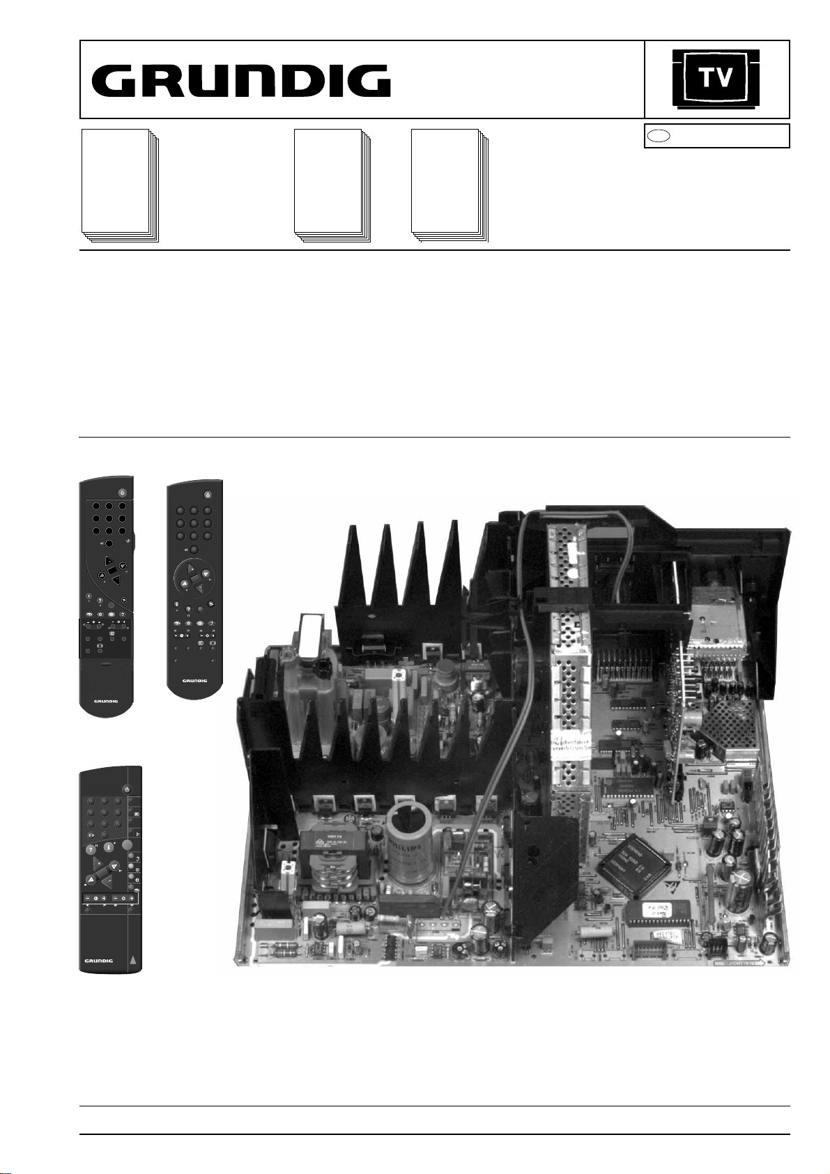
TP 900
(29642-061.11)
21
3
4 5 6
7 8 9
0
P
OK
P
TXT
SAT PIP
AUX
VIDEO
TP 800
(29642-061.01)
321
654
987
0
P
OK
P
TXT
SAT PIP
VIDEO
AUX
Service
Training
Sach-Nr./Part No.
72010-350.15
Boston ST 270/8 IDTV / LOG (9.21530-02 / G.CC 1275)
SE 7089 IDTV / LOG (9.21543-01 / G.CC 7092)
SER 151 E (9.28016-4144 / G.AC 2600)
CUC 1826
ST 72-261 IDTV / LOG (9.21528-01 / G.CD 8869)
ST 72-261/8 IDTV / LOG (9.21528-02 / G.CD 8969)
Atlanta SE 7289 IDTV / LOG (9.21529-01 / G.CC 8224)
SER 150 (9.28016-4143 / G.AY 4900)
D
Btx * 32700
CUC 1825
CUC 1826
(9.21529-01 / G.CC 8226)
#
TP 800
TP 900
TP 771
(29642-059.51)
123
456
789
VIDEO SAT
PIP
AUX
0
AV
TV
TXT
P
OK
P
TP 771
Bei einigen Modellen (72 cm-Geräte) müssen Sie für den Chassisausbau die Steckverbindungen zum Bedienteil lösen.
Für diesen Servicefall bietet der ZKD zur Vereinfachung der Reparatur
eine universelle Bedieneinheit Sach-Nr. 29305-165.59 (bestehend
aus Netzschalter und Infrarotempfänger) an.
Ersatzweise kann das Geräte-Bedienteil unterhalb der Bildröhre ausgebaut und wieder angesteckt werden.
For dismantling the chassis, the plug-in connections to the control unit
must be disconnected in some models (72 cm TVs).
For facilitating repairs in this case, the ZKD offers a universal keyboard
control unit, part no. 29305-165.59 (consisting of the mains switch and
infrared receiver).
Alternatively, the built-in keyboard control unit can be removed from
below the picture tube and reconnected.
Änderungen vorbehalten Printed in Germany Service Manual Sach-Nr.
Subject to alteration VK 22 0696 Service Manual Part No. 72010-019.30
Page 2

Allgemeiner Teil / General Section CUC 1825 / 1826
Es gelten die Vorschriften und Sicherheitshinweise gemäß dem Service Manual "Sicherheit",
Sach-Nummer 72010-800.00, sowie zusätzlich
die eventuell abweichenden, landesspezifischen
Vorschriften!
D
Inhaltsverzeichnis
Seite
Allgemeiner Teil........................... 1-1... 1-26
Modulübersicht .............................................................................1-3
Technische Daten.........................................................................1-4
Hinweise zu den Bauteilen und Oszillogrammen .........................1-6
Sicherheitshinweise, Servicehinweise.......................................... 1-7
Schaltplansymbole........................................................................1-8
Bedienungsanleitung Boston ST 270/8 IDTV LOG .................... 1-12
Service- und Sonderfunktionen ..................................................1-22
Abgleich ......................................... 2-1... 2-6
Abgleichlageplan ..........................................................................2-1
Chassisplatte ............................................................................... 2-3
Bildrohrplatte................................................................................ 2-4
Platinenabbildungen und
Schaltpläne ................................ 3-1… 3-39
Oszillogramme Chassisplatte ...................................................... 3-1
Oszillogramm-Meßpunkte-Chassisplatte ..................................... 3-3
Platinenabbildungen Chassisplatte ............................................. 3-5
Gesamtschaltplan Netz-Chassis ............................................... 3-11
Gesamtschaltplan Signal-Chassis............................................. 3-15
Bedieneinheit 29501-082.43...................................................... 3-19
Bedieneinheit 29501-082.44...................................................... 3-20
Bedieneinheit 29501-082.37/.46 ............................................... 3-21
Bedieneinheit 29501-082.25/.28 ............................................... 3-22
Bildrohrplatte 29305-122.04/.10 ................................................ 3-23
Tuner 29504-201.21 .................................................................. 3-25
Signal-Baustein 29504-102.34 .................................................. 3-27
Signal-Baustein 29504-162.34 .................................................. 3-29
Feature-Box 29504-103.37........................................................ 3-31
SAT-Baustein 29504-106.24 ..................................................... 3-35
Moevenentzerrungsplatte 29304-019.97................................... 3-39
The regulations and safety instructions shall be
valid as provided by the "Safety" Service Manual,
part number 72010-800.00, as well as the
respective national deviations.
GB
Table of Contents
Page
General Section........................... 1-1... 1-26
Module List .................................................................................. 1-3
Technical Data..............................................................................1-4
Hints to the Oscillograms and the Components ...........................1-6
Safety Advice, Service Notes .......................................................1-7
Circuit Diagram Symbols ..............................................................1-8
Operating Instructions Boston ST 270/8 IDTV LOG .................. 1-17
Service and Special Functions ...................................................1-22
Adjustments................................... 2-1... 2-6
Alignment Layout ..........................................................................2-1
Chassis Board ..............................................................................2-5
CRT Panel ................................................................................... 2-6
Layout of PCBs
and Circuit Diagrams ................ 3-1… 3-39
Oscillograms Chassis Board ....................................................... 3-1
Oscillogram Test Points Chassis Board ...................................... 3-3
Layouts of Chassis Board............................................................ 3-5
General Circuit Diagram Mains Chassis ................................... 3-11
General Circuit Diagram Signal Chassis ................................... 3-15
Control Unit 29501-082.43 ........................................................ 3-19
Control Unit 29501-082.44 ........................................................ 3-20
Control Unit 29501-082.37/.46 .................................................. 3-21
Control Unit 29501-082.25/.28 .................................................. 3-22
CRT Panel 29305-122.04/.10.................................................... 3-23
Tuner 29504-201.21 .................................................................. 3-25
Signal Module 29504-102.34..................................................... 3-27
Signal Module29504-162.34...................................................... 3-29
Feature-Box 29504-103.37........................................................ 3-31
SAT Module 29504-106.24........................................................ 3-35
N.S. Sea Gull Raster Correction PCB 29304-019.97................ 3-39
Ersatzteilliste ...............................4-1... 4-11
Allgemeiner Teil
Meßgeräte / Meßmittel
Regeltrenntrafo Meß-/Wobbelsender
Farbgenerator Oszilloskop
DC-Voltmeter NF-Voltmeter
NF-Generator Frequenzzähler
Beachten Sie bitte das Grundig Meßtechnik-Programm, das Sie unter
folgender Adresse erhalten:
Grundig electronics GmbH
Würzburger Str. 150
D-90766 Fürth/Bay.
Tel.0911/703-0
Telefax 0911/703-4479
Spare Parts List........................... 4-1... 4-11
General Part
Test Equipment / Aids
Variable isolating transformer Test/Sweep Generator
Colour Generator Oscilloscope
DC Voltmeter AF Voltmeter
AF Generator Frequency Counter
Please note the Grundig Catalog "Test and Measuring Equipment"
obtainable from:
Grundig electronics GmbH
Würzburger Str. 150
D-90766 Fürth/Bay.
Tel.0911/703-0
Telefax 0911/703-4479
GRUNDIG Service1 - 2
Page 3

GRUNDIG Service
ST 63-255
IDTV / LOG
ST 70-255
IDTV / LOG
ST 63-255/8
IDTV / LOG
ST 70-255/8
IDTV / LOG
M 70-280
IDTV / LOG
M 70-280/8
IDTV / LOG
ST 72-261
IDTV / LOG
ST 72-261/8
IDTV / LOG
Boston
ST 270
IDTV / LOG
Boston
ST 270/8
IDTV / LOG
Atlanta
SE 7289
IDTV / LOG
SE 7089
IDTV / LOG
Chassis 29701-096.01 29701-096.03 29701-096.02 29701-096.02 29701-096.01 29701-096.02 29701-096.11 29701-096.12 29701-096.01 29701-096.02 29701-096.11 29701-096.01
Tuner 29504-201.21 29504-201.21 29504-201.21 29504-201.21 29504-201.21 29504-201.21 29504-201.21 29504-201.21 29504-201.21 29504-201.21 29504-201.21 29504-201.21
Signal-Baustein
Signal Module
29504-102.34 29504-102.34 29504-162.34 29504-162.34 29504-102.34 29504-162.34 29504-102.34 29504-162.34 29504-102.34 29504-162.34 29504-102.34 29504-102.34
Bildrohrplatte
CRT Panel
29305-122.04 29305-122.04 29305-122.04 29305-122.04 29305-122.04 29305-122.04 29305-122.10 29305-122.10 29305-122.04 29305-122.04 29305-122.10 29305-122.04
Bedieneinheit
Control Unit
29501-082.25 29501-082.28 29501-082.25 29501-082.28 29501-082.44 29501-082.44 29501-082.43 29501-082.43 29501-082.37 29501-082.37 29501-082.46 29501-082.37
Feature-Box 29504-103.37 29504-103.37 29504-103.37 29504-103.37 29504-103.37 29504-103.37 29504-103.37 29504-103.37 29504-103.37 29504-103.37 29504-103.37 29504-103.37
Fernbedienung
Remote Control
29642-059.51
TP 771
29642-059.51
TP 771
29642-059.51
TP 771
29642-059.51
TP 771
29642-061.01
TP 800
29642-061.01
TP 800
29642-061.01
TP 800
29642-061.01
TP 800
29642-059.51
TP 771
29642-059.51
TP 771
29642-061.11
TP 900
29642-061.11
TP 900
Mövenentzerrungsplatte
N.S. Sea Gull Raster
Correction PCB
______29304-019.97 29304-019.97 _ _ 29304-019.97 _
SAT-Baustein
SAT Module
nachrüstbar/
retrofittable
29504-106.24 29504-106.24 29504-106.24 29504-106.24 29504-106.24 29504-106.24 29504-106.24 29504-106.24 29504-106.24 29504-106.24 29504-106.24 29504-106.24
Modulübersicht / Module List
CUC 1825 / 1826 Allgemeiner Teil / General Section
1 - 3
Page 4
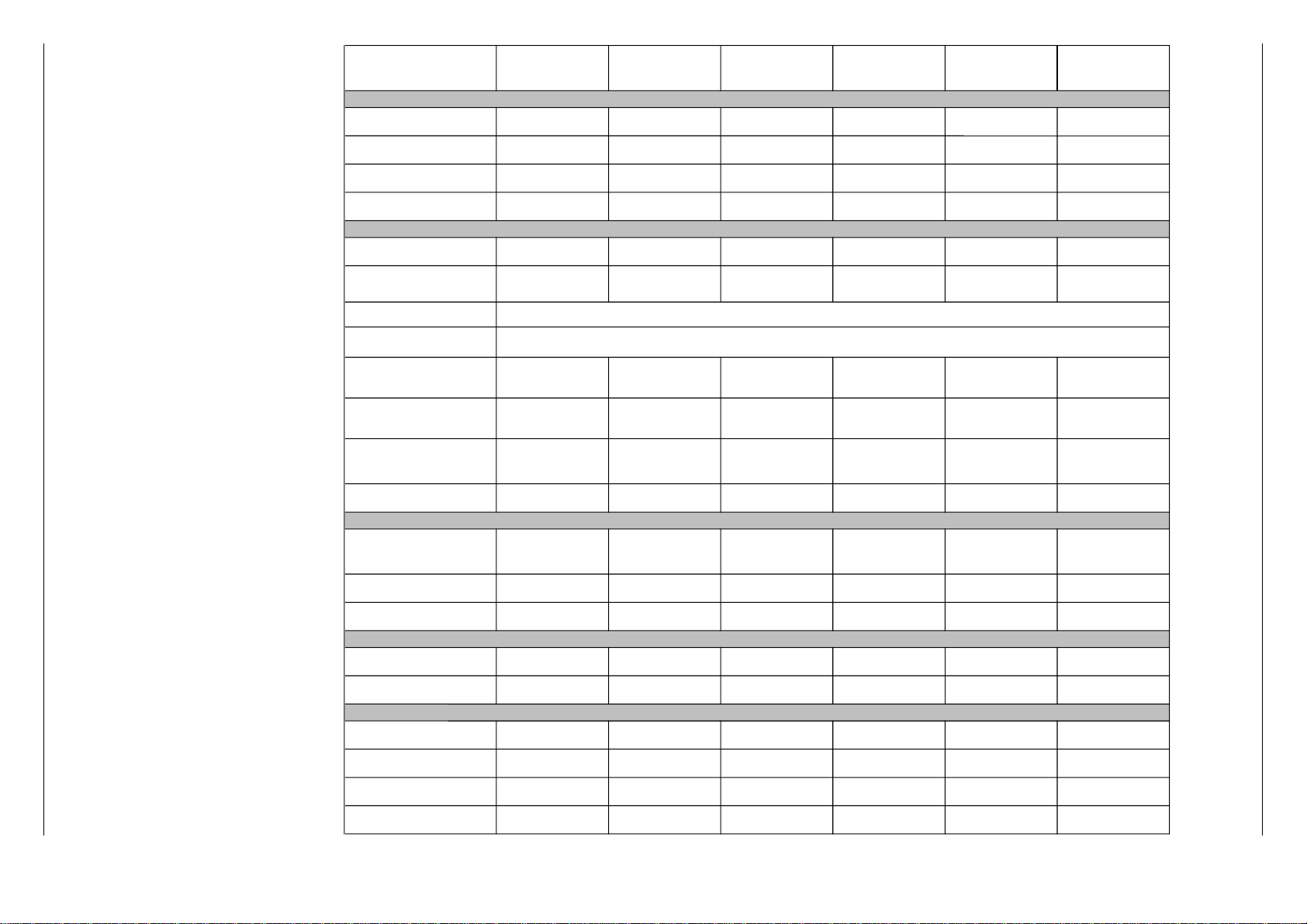
ST 70-255 IDTV/LOG ST 63-255 IDTV/LOG ST 70-255/8 IDTV/LOG ST 63-255/8 IDTV/LOG M 70-280 IDTV/LOG M 70-280/8 IDTV/LOG
Bildröhre / Picture Tube
Sichtbares Bild
Visible picture
66cm 59cm 66cm 59cm 66cm 66cm
Bildschirmdiagonale
Screen diagonale
70cm (28")
Megatron CCS
63cm (25")
Megatron CCS
70cm (28")
Megatron CCS
63cm (25")
Megatron CCS
70cm (28")
Megatron CCS
70cm (28")
Megatron CCS
Ablenkwinkel
Deflection angle
110° 110° 110° 110° 110° 110°
Bildwechselfrequenz
Vertical frequency
100Hz 100Hz 100Hz 100Hz 100Hz 100Hz
Elektronik / Electronic
Programmspeicherplätze
Programme positions
99 TV + 3 AV 99 TV + 3 AV 99 TV + 3 AV 99 TV + 3 AV 99 TV + 3 AV 99 TV + 3 AV
Perfect clear, Blue stretch,
Gamma adjustment
ja/yes ja/yes ja/yes ja/yes ja/yes ja/yes
AV-Auswertung
AV evaluation
auf jeden Programmplatz programmierbar / programmable for every programme position
Tuner Kabeltuner-Raster 8MHz für Hyperband / cable tuner - 8MHz spacing for hyperband
TV-Normen
TV-Standard
PAL/SECAM/
NTSC 4,43MHz, B/G
PAL/SECAM/
NTSC 4,43MHz, B/G
PAL/SECAM/NTSC4,43MHz,
B/G, I, DK/K'/D, L/L',
input AV: NTSC 3,58 MHz
PAL/SECAM/NTSC4,43MHz,
B/G, I, DK/K'/D, L/L',
input AV: NTSC 3,58 MHz
PAL/SECAM/
NTSC 4,43MHz, B/G
PAL/SECAM/NTSC4,43MHz,
B/G, I, DK/K'/D, L/L',
input AV: NTSC 3,58 MHz
Stereo Systeme
Stereo systems
Deutsch A2
German A2
Deutsch A2
German A2
Deutsch A2/German A2
Nicam 5,85+6,52
Deutsch A2/German A2
Nicam 5,85+6,52
Deutsch A2
German A2
Deutsch A2/German A2
Nicam 5,85+6,52
Videotext
Teletext
8-Seiten TOP/FLOF Text
mit VPS
8-pages TOP/FLOF text
with VPS
8-Seiten TOP/FLOF Text
mit VPS
8-pages TOP/FLOF text
with VPS
8-Seiten TOP/FLOF Text
mit VPS
8-pages TOP/FLOF text
with VPS
8-Seiten TOP/FLOF Text
mit VPS
8-pages TOP/FLOF text
with VPS
8-Seiten TOP/FLOF Text
mit VPS
8-pages TOP/FLOF text
with VPS
8-Seiten TOP/FLOF Text
mit VPS
8-pages TOP/FLOF text
with VPS
Musikleistung
Music power
2x20W 2x20W 2x20W 2x20W 2x20W 2x20W
Anschlüsse Front / Connections Front
Kopfhörer
Headphones
Stereo 3,5mm Klinken
Schaltbuchse /
Stereo 3.5mm jack switch
socket
Stereo 3,5mm Klinken
Schaltbuchse /
Stereo 3.5mm jack switch
socket
Stereo 3,5mm Klinken
Schaltbuchse /
Stereo 3.5mm jack switch
socket
Stereo 3,5mm Klinken
Schaltbuchse /
Stereo 3.5mm jack switch
socket
Stereo 3,5mm Klinken
Schaltbuchse /
Stereo 3.5mm jack switch
socket
Stereo 3,5mm Klinken
Schaltbuchse /
Stereo 3.5mm jack switch
socket
Video IN 1 x Cinch 1 x Cinch 1 x Cinch 1 x Cinch 1 x Cinch 1 x Cinch
Audio IN 2 x Cinch 2 x Cinch 2 x Cinch 2 x Cinch 2 x Cinch 2 x Cinch
Anschlüsse Rückwand / Connections Rear Panel
Euro AV 1(schwarz/black)
FBAS in-/output, RGB input,
S-Video input, Megalogic
FBAS in-/output, RGB input,
S-Video input, Megalogic
FBAS in-/output, RGB input,
S-Video input, Megalogic
FBAS in-/output, RGB input,
S-Video input, Megalogic
FBAS in-/output, RGB input,
S-Video input, Megalogic
FBAS in-/output, RGB input,
S-Video input, Megalogic
Euro AV 2 (orange)
FBAS in-/output, RGB input,
S-Video input
FBAS in-/output, RGB input,
S-Video input
FBAS in-/output, RGB input,
S-Video input
FBAS in-/output, RGB input,
S-Video input
FBAS in-/output, RGB input,
S-Video input
FBAS in-/output, RGB input,
S-Video input
Netzteil / Mains Stage
Netzspannung (Regelbereich)
Mains voltage (variable)
165 …264V 165 …264V 165 …264V 165 …264V 165 …264V 165 …264V
Netzfrequenz
Mains frequency
50 / 60Hz 50 / 60Hz 50 / 60Hz 50 / 60Hz 50 / 60Hz 50 / 60Hz
Leistungsaufnahme
Power consumption
ca. 120W ca. 120W ca. 120W ca. 120W ca. 120W ca. 120W
Standby ca. 7W ca. 7W ca. 7W ca. 7W ca. 7W ca. 7W
Technische Daten / Technical Data
Allgemeiner Teil / General Section CUC 1825 / 1826
GRUNDIG Service1 - 4
Page 5
GRUNDIG Service
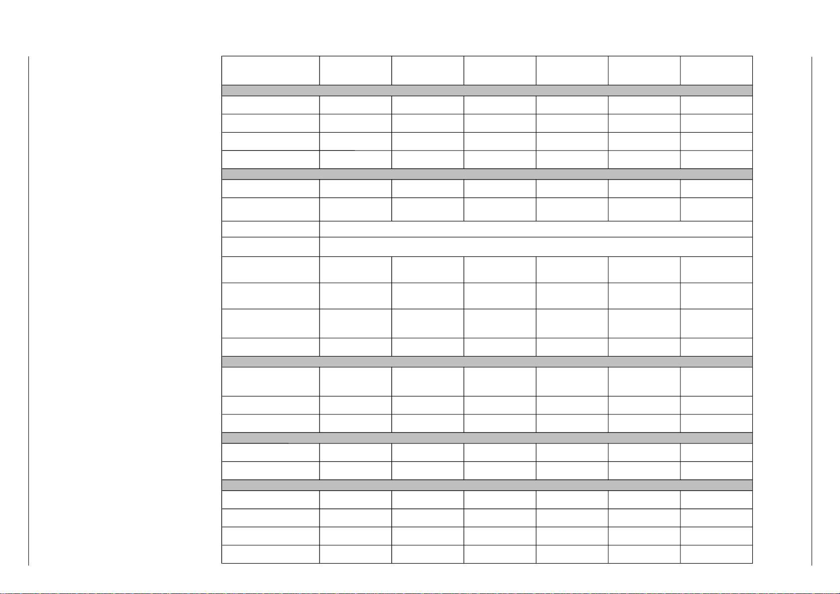
ST 72-261 IDTV/LOG ST 72-261/8 IDTV/LOG
Boston ST 270
IDTV/LOG
Boston ST 270/8
IDTV/LOG
Atlanta SE 7289
IDTV/LOG
SE 7089
IDTV/LOG
Bildröhre / Picture Tube
Sichtbares Bild
Visible picture
68cm 68cm 66cm 66cm 68cm 66cm
Bildschirmdiagonale
Screen diagonale
72cm (29"), Megatron,
Black Line S, Invar, CCS
72cm (29"), Megatron,
Black Line S, Invar, CCS
70cm (28"), Megatron
Black Matrix, CCS
70cm (28"), Megatron
Black Matrix, CCS
72cm (29"), Megatron
Black Line S, Invar, CCS
70cm (28"), Megatron
Black Matrix, CCS
Ablenkwinkel
Deflection angle
110° 110° 110° 110° 110° 110°
Bildwechselfrequenz
Vertical frequency
100Hz 100Hz 100Hz 100Hz 100Hz 100Hz
Elektronik / Electronic
Programmspeicherplätze
Programme positions
99 TV + 3 AV 99 TV + 3 AV 99 TV + 3 AV 99 TV + 3 AV 99 TV + 3 AV 99 TV + 3 AV
Perfect clear,
Blue stretch,
Gamma adjustment
ja/yes ja/yes ja/yes ja/yes ja/yes ja/yes
AV-Auswertung
AV evaluation
auf jeden Programmplatz programmierbar / programmable for every programme position
Tuner Kabeltuner-Raster 8MHz für Hyperband / cable tuner - 8MHz spacing for hyperband
TV-Normen
TV-Standard
PAL/SECAM/
NTSC 4,43MHz, B/G
PAL/SECAM/NTSC4,43MHz,
B/G, I, DK/K'/D, L/L',
in AV: NTSC 3,58 MHz
PAL/SECAM/
NTSC 4,43MHz, B/G
PAL/SECAM/NTSC4,43MHz,
B/G, I, DK/K'/D, L/L',
in AV: NTSC 3,58 MHz
PAL/SECAM/
NTSC 4,43MHz, B/G
PAL/SECAM/
NTSC 4,43MHz, B/G
Stereo Systeme
Stereo systems
Deutsch A2
German A2
Deutsch A2/German A2
Nicam 5,85+6,52
Deutsch A2
German A2
Deutsch A2/German A2
Nicam 5,85+6,52
Deutsch A2
German A2
Deutsch A2
German A2
Videotext
Teletext
8-Seiten TOP/FLOF Text
mit VPS
8-pages TOP/FLOF text
with VPS
8-Seiten TOP/FLOF Text
mit VPS
8-pages TOP/FLOF text
with VPS
8-Seiten TOP/FLOF Text
mit VPS
8-pages TOP/FLOF text
with VPS
8-Seiten TOP/FLOF Text
mit VPS
8-pages TOP/FLOF text
with VPS
8-Seiten TOP/FLOF Text
mit VPS
8-pages TOP/FLOF text
with VPS
8-Seiten TOP/FLOF Text
mit VPS
8-pages TOP/FLOF text
with VPS
Musikleistung
Music power
2x20W 2x20W 2x20W 2x20W 2x25W 2x20W
Anschlüsse Front / Connections Front
Kopfhörer
Headphones
Stereo 3,5mm Klinken
Schaltbuchse /
Stereo 3.5mm jack switch
socket
Stereo 3,5mm Klinken
Schaltbuchse /
Stereo 3.5mm jack switch
socket
Stereo 3,5mm Klinken
Schaltbuchse /
Stereo 3.5mm jack switch
socket
Stereo 3,5mm Klinken
Schaltbuchse /
Stereo 3.5mm jack switch
socket
Stereo 3,5mm Klinken
Schaltbuchse /
Stereo 3.5mm jack switch
socket
Stereo 3,5mm Klinken
Schaltbuchse /
Stereo 3.5mm jack switch
socket
Video IN 1 x Cinch 1 x Cinch 1 x Cinch 1 x Cinch 1 x Cinch 1 x Cinch
Audio IN 2 x Cinch 2 x Cinch 2 x Cinch 2 x Cinch 2 x Cinch 2 x Cinch
Anschlüsse Rückwand / Connections Rear Panel
Euro AV 1(schwarz/black)
FBAS in-/output, RGB input,
S-Video input, Megalogic
FBAS in-/output, RGB input,
S-Video input, Megalogic
FBAS in-/output, RGB input,
S-Video input, Megalogic
FBAS in-/output, RGB input,
S-Video input, Megalogic
FBAS in-/output, RGB input,
S-Video input, Megalogic
FBAS in-/output, RGB input,
S-Video input, Megalogic
Euro AV 2 (orange)
FBAS in-/output, RGB input,
S-Video input
FBAS in-/output, RGB input,
S-Video input
FBAS in-/output, RGB input,
S-Video input
FBAS in-/output, RGB input,
S-Video input
FBAS in-/output, RGB input,
S-Video input
FBAS in-/output, RGB input,
S-Video input
Netzteil / Mains Stage
Netzspannung (Regelbereich)
Mains voltage (variable)
165 …264V 165 …264V 165 …264V 165 …264V 165 …264V 165 …264V
Netzfrequenz
Mains frequency
50 / 60Hz 50 / 60Hz 50 / 60Hz 50 / 60Hz 50 / 60Hz 50 / 60Hz
Leistungsaufnahme
Power consumption
ca. 135W ca. 135W ca. 120W ca. 120W ca. 135W ca. 120W
Standby ca. 6W ca. 6W ca. 7W ca. 7W ca. 6W ca. 7W
Technische Daten / Technical Data
CUC 1825 / 1826 Allgemeiner Teil / General Section
1 - 5
Page 6
Allgemeiner Teil / General Section CUC 1825 / 1826
Hinweise zu den Oszillogrammen / Hints to the Oscillograms / Note relative agli Oscillogr./
Indications pour les Oscillogrammes / Observaciones con respecto a los Oscilogramas
D
Die Spannungswerte an den Oszillogrammen entsprechen Näherungswerten!
The voltages indicated in the oscillograms
are approximates!
I valori delle tensioni indicati sugli oscillogrammi sono approssimativi !
Les valeurs de tension indiquées pour les
oscillogrammes sont des valeurs approximatives!
Los valores de tensión en los oscilogramas
son aproximados!
GB
. . . V
ss
. . . ms/cm
. . . Hz
I
. . . V Gleichspannungswert / DC voltage / Valore tensione continua / Tension
continue / Valor de tensión continua
Spitze-Spitze - Wert / Peak to peak value / Valore picco-picco / Crêtecrête / Valor pico a pico
Zeitbasis des Oszilloskops / Time base of the oscilloscope / Base del
tempo dell´oscilloscopio / Base de temps de l´oscilloscope/ Base de
tiempo del oscilocopio
Frequenz / Frequency / Frequenza / Fréquence / Frecuencia
F
E
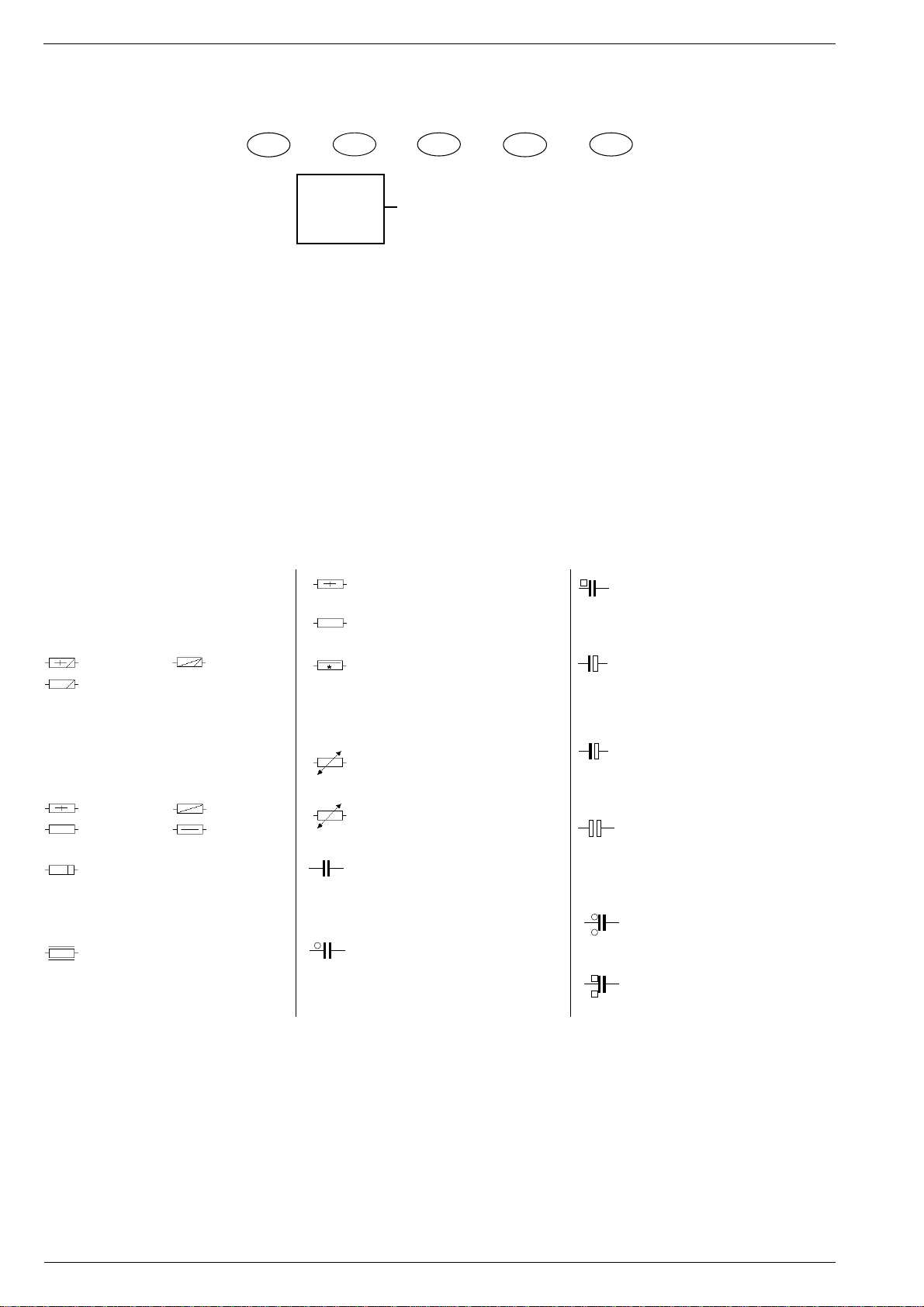
Hinweise zu den Bauteilen / Hints to Components / Istruzioni sui Componenti /
Observaciones sobre los Componentes / Precautions a observer
Metallschichtwiderstände
Metal film resistors
Resistenza a strato metallico
Resistencia de capa metálica
Film métallique
DIN 0204
DIN 0207
Kohleschichtwiderstände
Carbon film resistors
Resistenza a strato di carbone
Resistencia de capa de carbón
Film carbonique
DIN 0204
DIN 0207
Metalloxidwiderstand
Metal oxid resistor
Resistenza ad ossido metallico
Resistencia de óxido metálico
Métaloxide
Schwer entflammbarer Widerstand
Flame resistant resistor
Resistenza anti-infiammabile
Resistencia ininflamable
Ininflammable
DIN 0414
DIN 0414
DIN 0617
Sicherungswiderstand
SI-R
Safety resistor
Resistenza di sicurezza
Resistencia con resorte de seguridad
SI-R
Rés. fusible
Drahtwiderstand m. Wattangabe
Wire wound resistor w. wattage
Resistenza a filo
Resistencia bobinada (Disipación)
Bobinée avec ind. puissance
Heißleiter / NTC resistor
NTC
Termistore NTC / Resistencia CNT
Varistor (CTN)
Kaltleiter / PTC resistor
PTC
Termistore PTC / Resistencia CPT
Varistor (CTP)
Keramikkondensator
K
Ceramic capacitor
Condensatore ceramico
Condensador cerámico
Céramique
Kondensator, Capacitor
Condensatore, Condensador
Condensador, 250 V=
T
Kondensator, Capacitor
Condensatore, Condensador
Condensador, 630 V=
Elektrolytkondensator
Electrolytic capacitor
+
Condensatore elettrolitico
Condensador electrolitico
Electrolytique
Tantal-Elektrolytkondensator
Tantalum electrolytic capacitor
+
Condensatore elettro. al tantalio
Condensador de tantalio
Tantale
bipolarer Elektrolytkondensator
bipolar electrolytic capacitor
Condensatore elettrolitico bipolare
Condensador electrolitico bipolar
Electrolytique bipolaisé
Kondensator, Capacitor
Condensatore, Condensador
Condensador, 400 V=
Kondensator, Capacitor
Condensatore, Condensador
Condensador, 1000 V=
GRUNDIG Service1 - 6
Page 7

CUC 1825 / 1826 Allgemeiner Teil / General Section
Sicherheits-Hinweise
Die in den Fernsehgeräten auftretende Röntgenstrahlung entspricht
den Bestimmungen der Physikalisch-Technischen Bundesanstalt
vom 8. Januar 1987.
Die Hochspannung für die Bildröhre und die damit auftretende
Röntgenstrahlung ist abhängig von der exakten Einstellung der
Netzteilspannung +A.
Nach jeder Reparatur im Netzteil oder in der Horizontalablenkung ist
die Hochspannung zu messen und ggf. einzustellen.
Schutzschaltungen im Gerät dürfen nur kurzzeitig außer Betrieb
gesetzt werden, um Folgeschäden am Chassis oder an der Bildröhre zu vermeiden.
Beim Austausch der Bildröhre dürfen nur die in den Ersatzteillisten
vorgeschriebenen Typen verwendet werden.
D
Servicehinweise
Chassisausbau
Bevor Sie die Chassis-Verbindungsleitungen lösen, muß die Leitungsverlegung zu den einzelnen Baugruppen wie Netzschalterplatte, Bedieneinheit, Bildrohrplatte, Ablenkeinheit oder Lautsprecher beachtet werden.
Nach erfolgter Reparatur ist es notwendig, die Leitungsführung wieder
in den werksseitigen Zustand zu versetzen, um evtl. spätere Ausfälle
oder Störungen zu vermeiden.
Safety Advices
The X-radiation developing in the sets conforms to the X-radiation
Regulations (January 8, 1987), issued by the Physikalisch-Technische Bundesanstalt (federal physiotechnical institution).
The high tension for the picture tube and thus the developing Xradiation depends on the precise adjustment of the +A power
supply.
After every repair of the power supply unit or the horizontal deflection
stage it is imperative that the EHT for the picture tube is checked and
re-adjusted if necessary.
To avoid consequential damages to the chassis or the picture tube
the integrated protective circuits are allowed to be put out of
operation only for a short time.
When replacing the picture tube use only the types specified in the
spare parts lists.
Cable dereseau
Ces appareils ne peuvent être utilisés qu ' avec un cable de connecion
original de réseau avec bobine antiparasite intégré dans la fiche de
secteur. Ce câble de réseau empêche des perturbations de réseau et
est partie de l'autorisation d'appareil. Si nécessaire commandez
uniquement le cable de réseau selon la liste de pièces détachées.
Netzkabel
Diese Geräte dürfen nur mit dem Original-Netzanschlußkabel mit
integrierter Entstördrossel betrieben werden. Dieses Netzkabel verhindert Störungen aus dem Netz und ist Bestandteil der Gerätezulassung. Im Ersatzfall bestellen Sie bitte ausschließlich das Netzkabel laut Ersatzteilliste.
GB
Service Notes
Disassembly of the chassis
Before disconnecting the chassis connecting leads observe the way
they are routed to the individual assemblies like the mains switch
panel, keyboard control panel, picture tube panel, deflection unit or
loudspeaker.
On completion of the repairs the leads must be laid out as originally
fitted at the factory to avoid later failures or disturbances.
Mains cable
The TV receiver must only be operated with an original mains connecting
cable with an interference suppressor choke integrated in the mains
plug.This mains cable prevents interference from the mains supply and
is part of the product approval. For replacement please order exclusively
the mains connecting cable specified in the spare parts list.
F
Information pour la maintenance
Dèmontage de chassis
Avant de défaire les connecteurs du châssis princip, il y a lieu de
repérer auparavant les liaisons correspondant à chaque platine comme
par exemple le C.I. Inter secteur, le C.I. Commande, le C.I. Tube, le
bloc déviation ou les haut-parleurs.
A la fin de l'intervention, les connexions doivent être remises dans leur
position d'origine afin d'éviter par après d'éventuelles défaillances ou
perturbations.
I
Nota di servizio
Smontaggio del telaio
Prima di sfilare i cavi di collegamneto col telaio è necessario osservare
la disposizione originaria degli stessi verso le singole parti come la
piastra alimentazione, l'unità comandi, la piastra cinescopio, il giogo o
l'altoparlante.
Dopo la riparazione è necessario che gli ancoraggi e le guide
garantiscano la disposizione dei cavi analogamente a quella data in
fabrica e ciò per evitare disturbi o danni nel tempo.
Cavo rete
Gli apperechi devono essere messi in funzioni solo con il cavo originale
il colle gamento di rete e la sua spina di rete deve essere munita di una
bombina d´induttanza. In causa di sostituzione ordinate solo il cavo di
alimentatore che corrésponde alla lista degli accessori.
E
Nota de servicio
Desmontaje del chassis
Antes de desconectar las conecciones del Chassis hay que observar
la dirección de dichas conecciones a los distintos grupos de construcción
como la placa de conmutación de red, unidad de control, placa del
zócalo del tubo de imagen, unidad de deflección o altavoces.
Después de haber realizado la reparación y para evitar fallos o
pertubaciones posteriores es necesario reponer las conecciones tal
como fueron instaladas originalmente en fabrica.
Cable de red
El aparato solo se puede usar con el cable de red original con choque
antiparásito integrado en el enchufe de red. Este cable de red evita
perturbaciones de la red y es parte de la autorización del aparato. En
caso necesario puede pedir el cable de red según lista de piezas de
repuestos.
GRUNDIG Service
1 - 7
Page 8
Allgemeiner Teil / General Section CUC 1825 / 1826
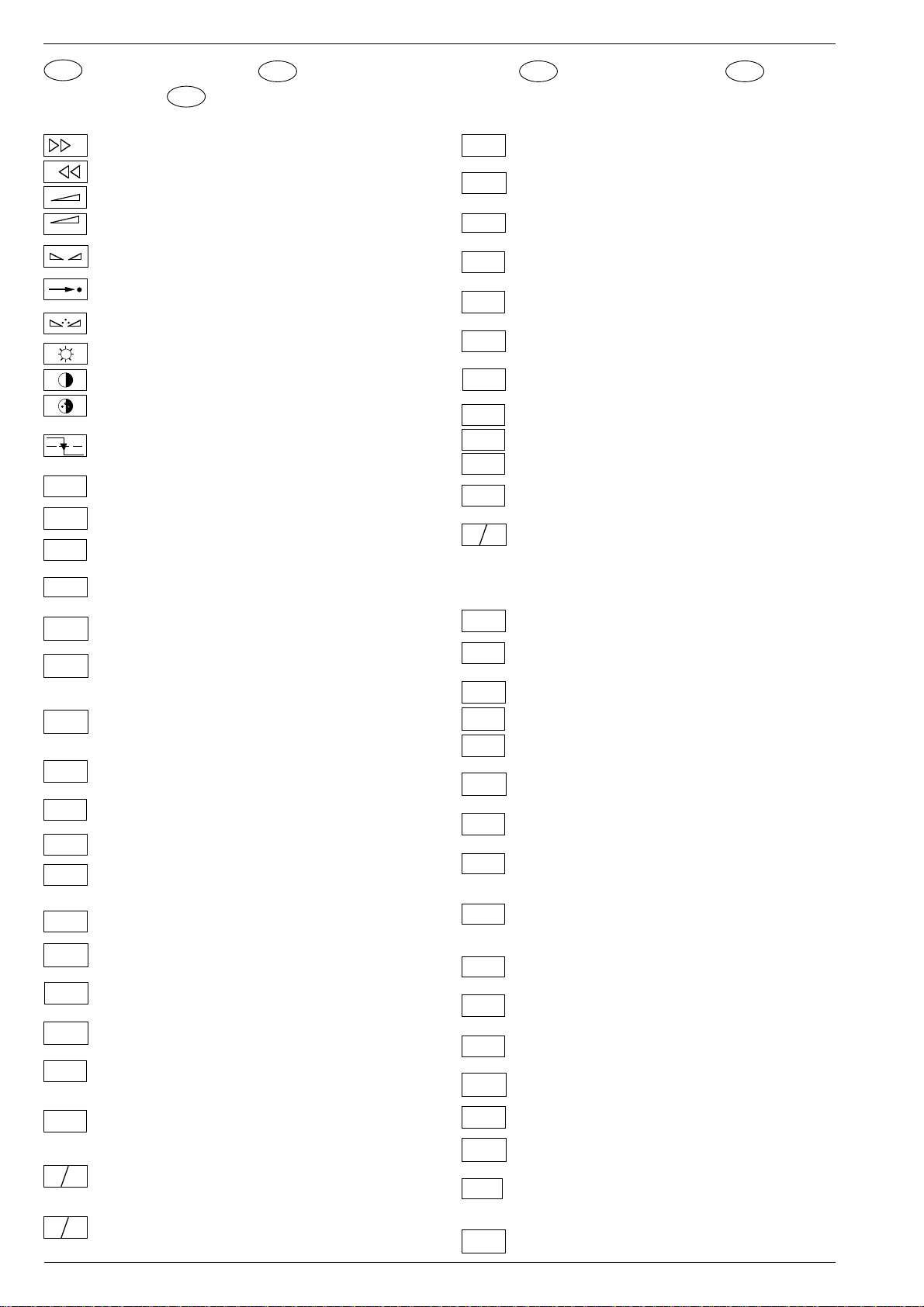
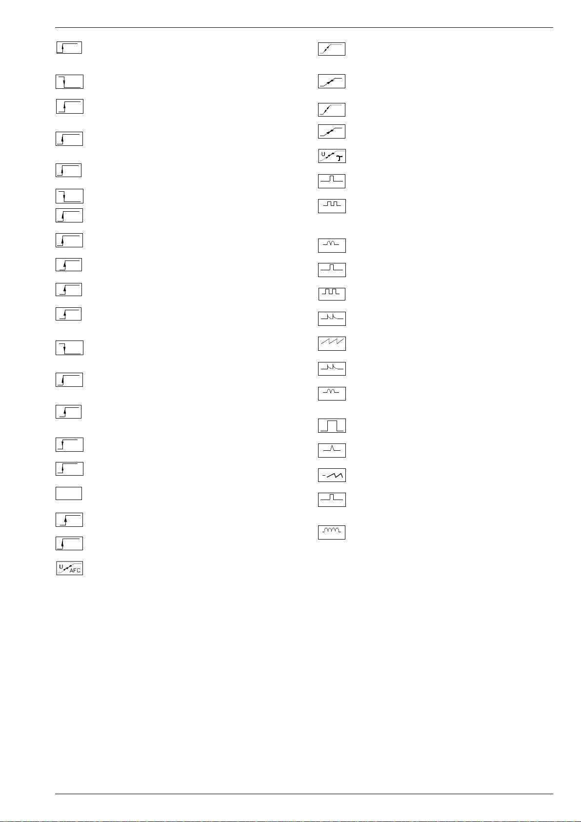
Schaltplansymbole
D
sullo schema
Feinabst. + / Fine tuning + / Réglage fine + / Sint. fine + / Sint. fina +
+
-
ABK
AUDIO
AUDIO-L
AUDIO-R
AUDIO
AUDIO
L - MAC
AUDIO
R - MAC
AUDIO
AUDIO
B
B
OSD
B
B/50
B/100
B-Y
B-Y
Feinabst. - / Fine tuning - / Réglage fine - / Sint. fine - / Sint. fina Lautstärke / Volume / Volume / Volume sonore / Volumen
Referenz Lautstärke / Volume ref. volt. / Tens. de réf. vol. sonore /
REF.
Tens di rif. volume / Tens. ref. volumen
Balance / Balance / Balance /Balanciam. / Balance
Suchlauf / Self seek / Recherche autom. / Sint. autom. / Sintonia
automatica
Farbton / Tint / Teinte / Tinta / Tinte
Helligkeit / Brightness / Luminosité / Luminosita / Brillo
Kontrast / Contrast / Contraste / Contrasto / Contraste
Farbkontrast / Colour contrast / Contraste des coleurs / Contrasto
colore / Contraste de color
Schutzschaltung / Protection circuit / Circuit de sécurité / Circuito di
protezione / Circuito de protección
(Burst Key): Burstaustastimpuls / Burst blanking pulse / Impulsion de
suppress. de burst / Imp. di soppress. del burst / Imp. supresion burst
Ton-Signal / Audio signal / Signal audio / segnale audio / Señal audio
Ton-Signal links / Audio signal left / Signal audio gauche / Segnale
audio sinistra / Señal audio izquierda
Ton-Signal rechts / Audio signal right / Signal audio droit / Segnale
audio destra / Señal audio derecha
Tonsignal D2 Mac / Audio signal D2MAC / Signal audio D2MAC /
MAC
Segnale audio D2MAC / Señal de sonido D2MAC /
Tonsignal links D2 Mac / Audio signal left D2MAC / Signal audio
gauche D2MAC / Segnale audio sinistro D2MAC / Señal de sonido
izquirdo D2MAC /
Tonsignal rechts D2 MAC / Audio signal right D2MAC / Signal audio
droit D2MAC / Segnale audio destro D2MAC / Señal de sonido
derecho D2MAC /
Audio-Signal FS Gerät / Audio signal TV set / Signal audio
TV
téléviseur / Segnale audio TV / Señal audio TV
Tonsignal VCR Gerät / Audio signal VCR unit / Signal audio
VCR
magnetoscope / Segnale audio VCR / Señal audio VCR
Blau-Signal / Blue signal / Signal bleu / Segnale blu / Señal azul
B
Rechner Stop I2C Bus frei / Computer Stop I2C Bus is free /
BB
Microprocesseur stop I2C Bus disponible / Calcol. stop I2C Bus
libero / Stop micropr. disponible
Basisband / Baseband / Bande de base / Banda base / Banda base
BB
Blau-Signal extern / Signal blue external /Signal bleu externe /
EXT
Segnale blu esterno / Señal azul externa
OSD-Einblendung blau / OSD blue / Eblouissement OSD bleu /
Visualizzazione OSD blu / Visualisacione OSD azul
Blau-Signal PIP / PIP Blue signal / Signal bleu PIP / Segnale blu
PIP
PIP / Señal azul PIP
Blau - Signal - 50Hz vert.,15625Hz hor. / Blue signal - 50Hz vert.,
15625Hz hor. / Signal bleu - 50Hz vert., 15625Hz hor. / Segnale bleu
- 50Hz vert., 15625Hz hor. / Señal azul - 50Hz vert., 15625Hz hor.
Blau-Signal -100Hz vert., 31250Hz hor. / Blue signal -100Hz vert.,
31250Hz hor. / Signal bleu -100Hz vert., 31250Hz hor. / Segnale blu
-100Hz vert., 31250Hz hor. / Señal azul -100Hz vert., 31250Hz hor.
B-Y -Signal - 50Hz vert., 15625Hz hor. / B-Y -Signal - 50Hz vert.,
50
15625Hz hor. / Signal B-Y - 50Hz vert., 15625Hz hor. / Segnale BY - 50Hz vert., 15625Hz hor. / Señal B-Y - 50Hz vert., 15625Hz hor.
B-Y -Signal - 100Hz vert., 31250Hz hor. / B-Y -Signal - 100Hz vert.,
100
31250Hz hor. / Signal B-Y - 100Hz vert., 31250Hz hor. / Segnale BY - 100Hz vert., 31250Hz hor. / Señal B-Y - 100Hz vert., 31250Hz hor.
Circuit Diagram Symbols
GB
E
Simbolos en los esquemas
C
CENTER
CHIP
AD
CINCH
AUDIO L
CINCH
AUDIO R
CHROMA
CHROMA
S-VHS
CLK
CL 1
CL 2
CSY
CS
100
DATA
DL
ENA
ENA
ZF
ENABLE
FT
ENABLE
LED
ENABLE
TON
EURO-AV
AUDIO-L
EURO-AV
AUDIO-R
EURO-AV
VIDEO
F
FBAS
FBAS
MAC
FBAS
TON
FBAS
TXT
FBAS
SYNC.
FBAS
S-VHS
Symboles schéma
F
Kanalwahl / Channel selection / Sélection de canaux / Selez.
canale / Seleccion canal
Mitttelpunkt-Lautsprecher / Center loudspeaker / Haut-parleur de
centre / Alto parlante punto centrale / Altavoz del centro
Chip Adresse / Chip adress / Chip direction / Indiri. del chip /
Direccion chip
Ton-Signal Cinch links / Audio signal cinch left / Signal audio cinch
gauche / Segnale audio cinch sinistra / Señal audio cinch izquierda
Ton-Signal Cinch rechts / Audio signal cinch right / Signal audio
cinch droit / Segnale audio cinch destra / Señal audio cinch derecha
Chroma Signal / Chroma signal / Signal dégree / Croma segnale /
Señal croma
Chroma S-VHS-Signal / Chroma S-VHS-Signal / Signal dégree de
S-VHS / Croma segnale S-VHS / Señal croma S-VHS
Clock
Composite Sync. Imp. für VT / Composite sync pulse for TT / Imp. de
sync. vidéo-composite pour TXT / Imp. hor. para Video Comp.
Kombiniertes Hor./vert. Sync. Signal 31250Hz/100Hz (Composite
Sync.) / Combined hor./vert. sync signal 31250Hz/100Hz (Composite Sync) / Signal synchr. hor./vert. combiné 31250Hz/100Hz
(Synchr. composité) / Segnale sincr. orizz./vert. 31250Hz/100Hz
(Sincr. Composito) / Señal combinada sincr. hor./vert. 31250/100Hz
(Sincr. compuesto)
Daten / Data / Données / Dati / Datos
Verzögerungsleitung / Delay line / Ligne à retard / Linea di ritardo /
Linea de retardo
Freigabe / Enable / Autorisation / Consenso / Habilitacion
Freigabe ZF / IF Enable / Validation FI / Consenso FI / Autorizacón FI
Freigabe FT / Finetuning enable / Autorisation Réglage fin / Abilitaz.
Sintonia fine / Habilitacion Sintoinia fina
Freigabe LED / LED enable / Autorisation LED / Abilitaz. LED /
Habilitacion LED
Freigabe Ton / Sound enable / Autorisation son / Abilitaz. audio /
Habilitacion sonido
Audio-Signal EURO-AV links / Audio signal EURO-AV left / Signal
audio EURO-AV gauche / Segnale audio EURO-AV sinistra / Señal
audio izquierda EURO-AV
Audio-Signal EURO-AV rechts / Signal audio EURO-AV right /
Signal audio EURO-AV droit / Segnale audio EURO-AV destra /
Señal audio derecha EURO-AV
Video-Signal EURO-AV / Video signal EURO-AV / Signal video
EURO-AV / Segnale video EURO-AV / Señal video EURO-AV
Farb-Signal / Chroma signal / Signal chroma / Segnale chroma /
Señal croma
FBAS-Signal / CCVS signal / Signal vidéo composite / Segnale video
composito / señal video compuesta
FBAS-D2 MAC / D2MAC CCVS signal / Signal vidéo compositeD2MAC / FBAS-D2MAC / FBAS-D2MAC
Basisband / Baseband / Bande de base / Banda base / Banda base
FBAS-Videotext / CCVS videotext / Signal vidéo composite-
Télétexte / FBAS-Televideo / FBAS-Teletexto
FBAS Sync. Signal / CCVS sync signal / Signal sync. vidéo col.
comp. / Segnal sincr. video col. comp. / Señal sincr. video
compuesta
FBAS Signal S-VHS / CCVS signal S-VHS / Signal vidéo col. comp. SVHS / Segnal video col. comp. S-VHS / Señal video compuesta S-VHS
Simboli
I
GRUNDIG Service1 - 8
Page 9

CUC 1825 / 1826 Allgemeiner Teil / General Section
HA
PIP
F
FRM
G
OSD
G
G
G/50
Hochspg. / EHT voltage / Haute tens. / Alta tens. / MAT
H
Rahmensignal / Frame signal / Signal d'encadrement / Segnale
cornice / Señal de marco
FT
Feinabstimmung / Fine tuning / Reglage fin / Sint. fine / Sint. fina
F
FU-Signal / FU-signal / Signal FU / Segnale FU / Senal FU
U
F
FV-Signal / FV-signal / Signal FV / Segnale FV / Senal FV
V
Grün-Signal / Green signal / Signal green external / Signal vert /
G
Segnale verde / Señal verde
OSD-Einblendung grün / OSD green / Eblouissement OSD vert /
Visualizzazione OSD verde / Visualisacione OSD verde
Grün-Signal PIP / Green signal PIP / Signal green PIP/ Signal vert
PIP
PIP / Segnale verde PIP / Señal verde PIP
Grün-Signal extern / Green signal vertical / Signal vert externe /
EXT
Segnale verde esterno / Señal verde externa
Grün-Signal - 50Hz vert.,15625Hz hor. / Green signal - 50Hz vert.,
15625Hz hor. / Signal vert - 50Hz vert., 15625Hz hor. / Segnale
verde - 50Hz vert., 15625Hz hor. / Señal verde -50Hz vert., 15625Hz hor.
Grün-Signal -100Hz vert., 31250Hz hor. / Green signal -100Hz vert.,
G/100
31250Hz hor. / Signal vert -100Hz vert., 31250Hz hor. / Segnale
verde -100Hz vert., 31250Hz hor. / Señal verde -100Hz vert.,
31250Hz hor.
GND - H
Nullpunkt Heizung / Ground filament / Point neutre-Chauffage /
Punto zero-Filamento / Punto medio filamento
Horiz. Sync. Impuls / Horiz. Sync pulse / Impulsion synchro. horiz. /
Impulso sincro orizzontale / Impulso de sinc. horiz.
Horiz. Ansteuerimpuls / Horiz. drive pulse / Impulsion de commande
HDR
horiz. / Impulso comando orizzontale / Impulso de control horiz.
Horiz. Klemmimpuls / Horiz. clamp pulse / Impulsion de serrage
HC
horiz. / Impulso comando orizzontale / Impulso de garras horiz.
Horiz. Rückschlagimpuls / Horiz. flyback / Impulsion de retour
HFB
horiz. / Impulso rotorno orizzontale / Impulso de retroceso horiz.
Hor. Sync. Implus für VT / Hor. sync pulse for TT / Imp. de sync. hor. pour
HS
TXT / Imp. sincr. orizz. per Televideo / Imp. hor. para Video Comp.
I
CLOCK
IDENT
RESET
IR CLK
IR DATA
VIDEO
AUDIO-L
Strahlstrom / Current beam / Current rayon / Corrante del irradire /
BEAM
Corriente de haz
I2C Bus -Clock
ICL
Infrarot-Signal / Signal infrared / Signal infra-rouge / Segnale
IR
infrarosso / Señal infrarojo.
IM
I2C Bus -Clock
I2C Bus -Kennung / I2C-Bus Identification / Identification I2C-Bus /
IM
Ident. I2C-Bus, Identification I2C-Bus
IM
I2C Bus -Reset
Infrarot Clock / Infrared clock / Signal I.R. horloge / Clock segnale
R.I. / Clock infrarojos
Infrarot Signal / Infrared signal / Signal I.R. / Segnale infrarosso /
Data infrarrojos
Infrarot Signal Video / Infrared signal video / Signal I.R. video /
IR
Segnale infrarosso video / Data infrarrojos video
Keyboard
KB
Tonsignal Kopfhörer links / Audio signal headphone left / Signal
KH
audio gauche de casque / Segnale audio sinistra cuffia / Señal audio
izquierda auriculares
AUDIO-R
audio droit de casque / Segnale audio sinistra cuffia / Señal audio
Tonsignal Kopfhörer rechts / Audio signal headphone right / Signal
KH
derecha auriculares
Lautstärke / Volume / Volume / Volume sonore / Volumen
L
LED
Leuchtdiode / Light emitting diode / Diode lumineuse / Diodo
luminoso / Diodo luminescente
Speicher Taste / Memory button / Touche mémoire / Tasto di
M
memoria / Puls. memoria
GRUNDIG Service
MEGA
LOGIC
MODE
NIC CLK
NORM
OWA
P
P/C
P1
R
REMOTE
R
OSD
R
PIP
R
EXT
R-Y
50
R-Y
100
S
SB
SCL
SCL 100
SDA
SHIFT
VIDEO
SHIFT
TEXT
SS
SSB
SSC
SSC
PIP
SSC
100
SSC
50
SUR-
ROUND
Megalogic Daten / Megalogic data / Megalogic dates / Dati
Megalogic / Megalogic datas
Modus / Mode / Mode / Modo / Modo
NICAM Clock / Clock NICAM / Horloge NICAM / Clock NICAM /
Clock NICAM
Norm Taste / TV standard select button / touche de norme / Tasto
norma / Puls. de norma
Ost-West Ansteuerimpuls / East-west drive impuls / Impulsion de
commande Est-Ouest / Impulso comando Est-Ovest / Impulso de
control Este-Oeste
Programm / Program / Programme / Programma /Programa
Programm-Kanalwahl / Program channel selection / Progr. sélection
de canaux / Progr. selez.canale / Progr. selec. canal
Bild im Bild / Picture in picture / Image dans l'image / PIP / Imagen
en la imagen
Progr. Taste / Progr. button / Touche Progr. / Tasto Progr. / Puls.
Progr.
Rot-Signal / Red signal / Signal rouge / Segnale rosso / Señal rojo
Fernbedienung / Remote control / Telecommande / Telecomando /
Mando a distancia
OSD-Einblendung rot / OSD red / Eblouissement OSD rouge /
Visualizzazione OSD rosso / Visualisacione OSD rojo
Rot-Signal PIP / Red signal PIP / Signal rouge PIP / Segnale rosso
PIP / Señal rojo PIP
Rot-Signal extern / Signal red external / Signal rouge externe /
Segnale rosso esterno / Señal rojo externa
R-Y -Signal - 50Hz vert., 15625Hz hor. / R-Y -Signal - 50Hz vert.,
15625Hz hor. / Signal R-Y - 50Hz vert., 15625Hz hor. / Segnale RY - 50Hz vert., 15625Hz hor. / Señal R-Y - 50Hz vert., 15625Hz hor.
R-Y -Signal - 100Hz vert., 31250Hz hor. / R-Y -Signal - 100Hz vert.,
31250Hz hor. / Signal R-Y - 100Hz vert., 31250Hz hor. / Segnale
R-Y - 100Hz vert., 31250Hz hor. / Señal R-Y - 100Hz vert., 31250Hz hor.
Sonderkanal / Special channel / Canal special / Canale speciale /
Canal especial
Strahlstrombegrenzung / Beam current lim. / Lim. cour. de faisceau /
Lim. corr. di raggio / Corriente media de haz
I2C-Bus Clock
Schneller I2C-Bus Clock / I2C-Bus clock high speed / I2C-Bus grande
vitesse / I2C-Bus veloce / Clock del I2C-Bus de alta velocida
I2C-Bus Daten / I2C-Bus data / I2C-Bus données / I2C-Bus dati /
I2C-Bus datos
Dynamische vert. Versch. 25Hz, aktiv bei Video u. Mix Betrieb /
Dynam. vert. shift 25Hz, active on video and mix operation / Decal
dynam. de l'image 25Hz, actif sur video et fonction. mixte / Spostam.
vert. dinam. 25Hz, attivo con video e. funzionam. misto / Desplaz.
dinamico vert. 25Hz, activo con video Y funciones mixtas
Dynamische vert. Versch. 25Hz, aktiv bei Standbild u. VT / Dyn. vert.
shift 25Hz, active on freeze-frame and Teletext / Decal dynam. de
l'image 25Hz, actif sur arret immage et Vidéotext (Antiope) / Spostam.
vert. dinam. 25Hz, attivo con fermo immag. e Televideo / Desplaz.
dinamico vert. 25Hz, activo con imagen parada Y Videotexto
Schutzschaltung / Protection circuit / Cablage protecteur / Pot. de
prot. / Circuito de proteccion
Spitzenstrahlstrombegrenzung / Peak beam current limiting / Lim.
de faisceau crete / Lim. corr. catod. di pico / Corrente pico de haz
Supersandcastle
Supersandcastle PIP
Supersandcastle 100Hz vert., 31250Hz hor.
Supersandcastle 50Hz vert., 15625Hz hor.
Surround
1 - 9
Page 10

Allgemeiner Teil / General Section CUC 1825 / 1826
-
SYNC
SYNC.
BTX
SYNC.
VT
SW
TE
T1
T2
T T
U
FOC
U
G1
U
U
SG
U
G 2
VA
VB
VCL
VDR
VG
VIDEO
VT DATA
VT SCL
VT SDA
Y
Y
50
Y
100
ZF
AFC
U
U
AV
U
BA
U
BTX
U
C-AV
Sync.-Signal / Sync.-Signal / Signal sync / Segnale sync. / Señal de sync.
Sync. BTX / Viewdata Sync / Sync. Télétext / Sincr. Videotel / Sincr.
Videotexto
Sync. VT / Sync. Teletext / Sync Vidéotexte / Sincr. Televideo / Sincr.
Videotexto
Schwarzwert / Black level / Niveau du noir / Livello del nero / Nivel
de negro
TEXT-Freigabe / TEXT enable / Autorisation TEXTE / Abilitaz.
TELEVIDEO / Habilatation TEXTE
Bei Zweiton, Ton 1 / On two channel sound, sound 1 / Pour double
son, son 1 / In bicanale, audio 1 / En dual, sonido 1
Bei Zweiton, Ton 2 / On two channel sound, sound 2 / Pour double
son, son 2 / In bicanale, audio 2 / En dual, sonido 2
Tieftöner / Woofer / Haut-parleur pour les frequences basses / Toni
bassi / Sonido bajo
Fokusspg. / Focussing volt. / Tens. de focalis. / Tens di focalizz. /
Tens focalizacion
Spg. Gitter 1 / Volt. grid 1 / Tens grille G 1 / Tens. griglia 1 / Tens.
rejillas G 1
H
Hochspannung / High voltage / Haute tension / EAT / Alte tension
Schirmgitter Spg. / Screen-grid volt. / Tens. de grille - écran / Tens.di
griglia schermo / Tens. de rejilla
Vertikaler Ansteuerimpuls / Vert. drive pulse / Impulsion de
commande verticale / Impulso di comando verticale / Impulso de
control vertical
VCR - Clock
Freigabe Anzeigebaustein / Display enable / Autorisation pour
module indicateur / Modulo indicazione / Habilitacion modulo
indicacion
Vert. Gegenkopplung / Vert. feedback / Contre-reaction verticale /
Controreazione vert. / Aliment. neg. vert.
Video Signal / Video signal / Signal vidéo / Segnale video / Señal
video
VT Daten / Teletext data / Données Teletexte / Linea dati Televideo /
Data Teletexto
Videotext Clock / Teletext clock / Signal horloge Vidéotext / Clock
Televideo / Clock Teletexto
I2C Bus: VT Daten / Teletext data / Données Vidéotext / Dati
Televideo / Data Teletexto
Y-Signal / Y Signal / Signal Y /Segnale Y / Señal Y
Y -Signal - 50Hz vert., 15625Hz hor. / Y -Signal - 50Hz vert.,
15625Hz hor. / Signal Y - 50Hz vert., 15625Hz hor. / Segnale
Y - 50Hz vert., 15625Hz hor. / Señal Y - 50Hz vert., 15625Hz hor.
Y - Signal - 100Hz vert., 31250Hz hor. / Y -Signal - 100Hz vert.,
31250Hz hor. / Signal Y - 100Hz vert., 31250Hz hor. / Segnale
Y - 100Hz vert., 31250Hz hor. / Señal Y - 100Hz vert., 31250Hz hor
Zwischenfrequenz / IF / FI / FI / FI
Schaltspg. AFC / AFC switching volt. / Tens. de commut. AFC/ Tens.
di commut. AFC / Tens. conmut. CAF
Schaltspg. AV / Switching volt. AV / Tens. de commut. AV / Tens. di
commut. AV / Tens. conmut. AV
Schaltspg. Bildamplitude / Switching voltage vertical amplitude /
Tension de coupure amplitude dìmage / Tensione di commutaz.
ampiezza d'imagine / Tension de conm. amplitude de imagen di
commut. PAL / Tens. conmut. PAL
Schaltspg. BTX / Switching volt. BTX (Viewdata) / Tens. commut.
Télétext / Tens. commut. VIDEOTEL / Tens. conmut. Teletexto
Schaltspg. Camera Wiederg. über C-AV Eingang/ Switching volt.
cam. playback via C-AV input / Tens de commut pour lec. de camera
par l'entree C-AV / Tens.de commut. in riproduz. cam tramite ingresso
C-AV / Tens. de serv. reprod. camera a traves de la entrada C-AV
U
CAM
AV
U
DATA
U
U DAT A
EXT
U
DEEM
U
DS
U
MAC
U
EURO-
AV
U
EU-AV
CINCH
U
FBAS
U
HIFI
U
HI FI
MUTE
U
HUB
U
IDENT
U
KH
MUTE
U
KLEMM
U KOIN
50/60Hz
KOIN
U
VQ
U
LED
U
Leucht
punkt
U
LNC
OFF
U
MUTE
U
NF 1
U
NF 2
U
NIC
U
NORM
U
PAL
U
POL.
Schaltspg. Camera Wiedergabe / Switching volt. camera playback /
Tens. commut. reprod. camera / Tens. commut. riproduz. telecam /
Tens. conm. reprod. camara
Schaltspg. Datenbetr. / Switching volt. data mode / Tens. de commut. fonct. données / Tens. di commut. dati / Tens conmut. datos
Schaltspg. U Data extern / Switching volt Data ext. / Tension de
commutation U Data externe / Tens. di commutazione U-Data
esterno / Tensión de conmutatón externa U
Schaltspg. Deemphasis / Switching volt. deemphasis / Tens. commut. desaccent. / Tens. commut. deenfasi / Tens. conmut. deenfasis
Schaltspg. Dolby-Surround / Switching volt. Dolby-Surround / Tens.
commut. Dolby-Surround / Tens. commut. di Dolby-Surround / Tens.
de conmut. Dolby-Surround
Schaltspg. D2MAC / Switching volt. D2MAC / Tension de
commutation D2MAC / Tens. di commtazione D2MAC / Tensión de
conmutación D2MAC
Schaltspg. EURO-AV / Switching volt. EURO-AV / Tens. de commut.
EURO-AV / Tens. di commut. EURO-AV / Tens. conmut. EURO-AV
Schaltspg. EURO-AV-Cinch-Buchse / Switching volt. EURO-AVCinch socket / Tens. commut. prisa Scart - Cinch / Tens. commut.
presa Scart -Cinch / Tens. conm. EURO-AV - Cinch
Schaltspannung für Video-Ausgang EURO-AV Buchse / Switch.
voltage for video output EURO-AV socket / Tension de commut.
pour sortie vidéo EURO-AV / Tension commut. per presa d'uscita
video EURO-AV / Tension de conmut. para salida EURO-AV
Schaltspg. HIFI / Switching voltage HIFI / Tens. de commut. HIFI /
Tens di commut. HIFI / Tens. conmut. HIFI
Stummschaltung HiFi / Muting volt. HiFi / Commutation de silence
HiFi / Silenzametno HiFi / Muting HiFi
Schaltspg. HUB / Switching volt. deviation / Tens. commut.
déviation / Tens. commut. deviazione / Tens. conmut. deviacion
Schaltspg. Signalkennung AV 3 / Switching volt. signal identification
AV 3 / Tens de commut.identification de signal AV3 / Tens. commut.
identificazione segnale / Tens. conmut. identifi. segñal AV3
Stummschaltung Kopfhörer / Muting volt. headphone / Commutation
de silence casque / Silenzamento cuffia / Muting auriculares
Gleichspannung für SAT-Basissignal / DC for SAT basic signal /
Tens. continue pour SAT base signal / Tens continua per segnale
SAT base / Tens. continua para segñal SAT base
Schaltspg. Koinz. / Switching volt. coinc. / Tens de commut. coinc. /
Tens di commut. coinc. / Tens. conmut. coinc.
Schaltspg. Koinz. mit Videoquelle verknüpft / Coinc. switching volt.
linked with video source / Signal de coincid. combiné avec source
video / Tens. di commut. a coinc. combinata con sorg video segñal
de coincidencia combinada con video
Schaltspg. LED / Switching volt. LED / Tens de commut. LED / Tens.
commut. LED / Conmut. LED
Schaltspg. Leuchtpunktunterdrückung / Switching volt. beam spot
suppression / Tens. de commut. suppress. du spot lumineux / Tens.
soppr. punto luminoso / Tens. de conmut. filtro supresor del punto luz
Schaltspg. LNC "Aus" / Switching volt. LNC "OFF" / Tens. de
commut. LNC "OFF" / Tensione di commut. "Spento" LNC / Tension
LNC "OFF"
Stummschaltung / Muting / Silencieux / Silenziamento /Muting
Schaltspg. NF 1 / Switching volt. AF 1 / Tension commut. BF 1 / Tens.
commut BF 1 / Tens. conm. BF 1
Schaltspg. NF 2 / Switching volt. AF 2 / Tension commut. BF 2 / Tens.
commut BF 2 / Tens. conm. BF 2
Schaltspg. NICAM / Switching volt. NICAM / Tens. de commut.
NICAM / Tens. commut. NICAM / Tens. de conmut. NICAM
Schaltspg. Norm / Switching volt. Norm / Tens. de commut.
standard / Tens. di commut. Norma / Tens. conmut. Norma
Schaltspg. PAL / Switching volt. PAL / Tens. de commut. PAL / Tens
Schaltspg. Polarität / Switching volt. polarity / Tension commut.
polarite / Tens. commut. polarita / Tens. conmut polarizacion
GRUNDIG Service1 - 10
Page 11
CUC 1825 / 1826 Allgemeiner Teil / General Section
U
POWER
OFF
U
RESET
U
RGB
U
SCHUTZ
U
SEC
STAND
U
U
S-VHS
U TON
1/2
U
UHF
U
VHF
U
VQ
U
WISCH
U
W/N
U
I / III
U
14V
U
22kHz
0/3/6/9V
U
4.5MHz
U
50/60
HZ
Schaltspg. Ökoschalter / Switching volt. eco switch / Tens. de
commut. interr. eco. / Tens. commut. interr. ecologico / Tens.
conmut. interr. ecol.
Schaltspg. Reset / Switching volt. Reset / Tens. commut. Reset /
Tens. commut. Reset / Tens. conmut. Reset
Schaltspg. RGB1 - RGB2 / Switching volt. RGB1 - RGB2 / Tens. de
commut. RGB1 - RGB2 / Tens. di commut. RGB1 - RGB2 / Tens.
conmut. RGB1 - RGB2
Schaltspg.-Schutzfunktion / Switching volt.-protective func. / Tens
de commut.-sécurité / Tens. di commut.-funz di protez. / Tens.
conmut.-proteccion
Schaltspg. SECAM / Switching volt. SECAM / Tens. de commut.
SECAM / Tens. di commut. SECAM / Tens. conm. SECAM
Schaltspg. Standby / Switching volt. Standby / Tens. commut.
BY
Veille / Tens. commut. Standby / Tens. conmut. Standby
Schaltspg. S-VHS / Switching volt. S-VHS / Tens.de commut.
S-VHS / Tens. de commut. S-VHS / Tens. de conmut. S-VHS
Schaltspg. Ton 1-2 / Switching volt. sound 1-2 / Tens. commut. audio
1-2 / Tens. commut. son 1-2 / Tens. conmut. son 1-2
Schaltspg. UHF / UHF switching volt. / Tens. de commut. UHF / Tens
di commut. UHF / Tens. conmut. UHF
Schaltspg. VHF / VHF switching volt. / Tens. de commut. VHF / Tens
di commut. VHF / Tens. conmut. VHF
Schaltspg. Videoquelle / Switching volt. video source / Tens. de
commut. source video / Tens. di commut. sorg. video / Tens conmut.
video
Schaltspg. Wischerkontakt / Schwitching voltage temp. contact /
Tens. de commut. contact fugitif / Tens. commut. contatto / Contacto
supresor tens. de conmut.
Schaltspg. ZF breit - schmal / IF switching volt. wide - narrow / Tens.
commut. FI large - etroit / Tens. commut. FI larga - stretta / Tens. FI
ancho - estrecho
Schaltspg. Bandwahl / Band sel. switching volt. / Tens. de commut.
select. bande / Tens. di commut. selez. banda / Tens. conmut. selec.
banda
14V Schaltspg. / 14V switching volt. / Tens. commut. 14V / Tens.
commut. 14V / Tens. de conm. 14V
22kHz Schaltspg. / 22kHz switching volt. / Tens. commut. 22kHz /
Tens. commut. 22kHz / Tens. de conm. 22kHz
0/3/6/9V Schaltspg. / 0/3/6/9V switching volt. / Tens. commut.
0/3/6/9V / Tens. commut. 0/3/6/9V / Tens. de conm. 0/3/6/9V
Schaltspg. 4,5MHz / Switching volt. 4.5MHz / Tens. de commut.
4,5MHz / Tens. di commut. 4,5MHz / Tens conmut. 4,5MHz
Schaltspg. 50-60Hz / Switching volt. 50-60Hz / tens. de commut.
50-60Hz / Tens. di commut. 50-60Hz / Tens. conmut. 50-60Hz
Regelspg. AFC / AFC contr. volt. / Tens. de regul. AFC / Tens. di
contr. AFC / Tens. regul. CAF
U
AFC
SAT
U
AGC
U
RE
U
TUN.
HOR.
HOR.2FH
VERT.
VERT.
VER. 2FV
VERT.
VERT.
VERT.100
VERT.100
REF.
PULSE
O/W
Regelspg. AFC Satellitentuner / AFC contr. volt. SAT tuner / Tens.
de regul. AFC tuner SAT / Tens. di contr. AFC Tuner SAT / Tens.
regul. CAF Tuner SAT
Feldstärkeabhängige Spg. / Fieldstrength-depent volt. / Contr. automatique de gain / Tens. dipent. intens. campo / Contr. autom. de gain
tens. CAG
Regelspg. / Contr. volt. / Tens. de regul. / Tens. di contr. / Tens regul.
Abstimmspg. Tuner / Tuning volt. tuner / Tens. d'accord tuner / Tens.
di sintonia tuner / Tens. sintonia tuner
Regelspg. Verzög. / Delayed contr. volt. / Tens. de regul. retardee /
Tens. regul. retardada
Horizontale Ansteuerung / Horiz. drive / Synchr. lignes / Pilotaggio
orizz. / Exitación horiz.
31250Hz Ansteuerimp. für Zeilenendstufe / 31250Hz Triggering
pulse for horiz. output / 31250Hz commande pour l'étage final
lignes / Imp. Pilotaggio di 31250Hz per stadio finale di riga / Impulso
de exitación 31250Hz para paso final de lineas
Vert. Parabel / Vert. parabolic signal / Signal parabolique vert. /
Segnale parab. vert. / Senal parabolica vert.
Vert. Tastimpuls / Vert. Gating pulse / Imp. trame / Imp. a cadenza
vert. / Imp. cuadro
Vert. Tastimpuls 100Hz / Vert. Gating pulse 100Hz / Imp. trame
100Hz / Imp. a cadenza vert. 100Hz / Imp. cuadro 100Hz
Vert. Sägezahn / Vert. saw tooth / Signal dent de scie / Dente di sega
vert. / Dientede sierra vert.
Vert. Tastimpuls / Vert. Gating pulse / Imp. trame / Imp. a cadenza
vert. / Imp. cuadro
Vert Sägezahn 100Hz / Vert saw tooth 100Hz / Signal dent de scie
100Hz / Dente di sega vert. 100Hz / Dientede sierra vert. 100Hz
Vert. Parabel 100Hz / Vert. parabolic 100Hz signal / Signal parabolique 100Hz vert. / Segnale parab. vert. 100Hz / Senal parabolica
vert. 100Hz
Tastimpuls / Gating pulse / Impuls de declenchement /Impulso a
cadenza / Imp. puerta
Ref. Impuls hor. / Reference impulse hor. / Imp. de refer.hor. / Imp.
di rifer. hor. / Imp. refer. horiz.
Klemmung Ein-Aus / Clamping On-Off / Clampage Marche-Arrêt /
Clamping Ins.-Disins. / Clamping Enc.-Apag.
Pulse für Polarotor / Pulses for Polar-Rotor / Impulsions Rotor de
Polariastion / Impulsi per Rotore Polarizzazione / Impulsos dara
Polarrotor
O-W Amplitude / E-W amplitude / Amplitude E-O / Ampiezza E-O /
Amplitud E-O
GRUNDIG Service
1 - 11
Page 12
Allgemeiner Teil / General Section CUC 1825 / 1826
1 - 12 GRUNDIG Service
Bedienungsanleitung Boston ST 270/8 / IDTV/LOG
Hinweis:
Dieses Kapitel enthält Auszüge aus der Bedienungsanleitung. Weitergehende Informationen
entnehmen Sie bitte der gerätespezifischen Bedienungsanleitung, deren Sachnummer Sie in der
entsprechenden Ersatzteilliste finden.
❒
Das Senderspeicher-System
»ATS euro plus«
Dieses Gerät ist mit »ATS euro plus« (Auto Tuning
System) ausgestattet. Der besondere Komfort dieses
neuen Systems ist die automatische Programmplatzbelegung.
Dieses sog. Programmspeicher-System tastet den
gesamten Empfangsbereich ab, speichert die
gefundenen Programme und trägt sie mit dem
dazugehörigen Sendernamen (Kürzel) in eine Tabelle ein.
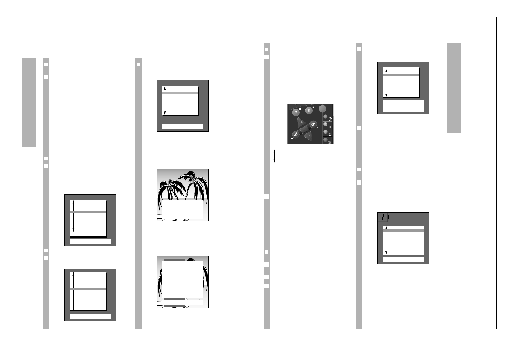
Nach dem Einschalten des Gerätes erscheint die
Einblendung »Dialogsprache einstellen«.
w
!
Erscheint die Seite nicht, dann drücken Sie an der
Fernbedienung nacheinander die Tasten h und G.
Das DIALOG CENTER blendet sich ein (siehe Abb.
Seite 5, rechts). Gehen Sie dann wie dort ab
beschrieben vor.
❒
Dialogsprache einstellen
Für den Dialog zwischen Ihnen und dem Fernsehgerät kann aus mehreren Sprachen gewählt werden. Die Einblendungen der Benutzerführung erfolgen in der gewählten Sprache.
Ab Werk ist F eingestellt. Entspricht Ihnen diese
Sprache, brauchen Sie nur Taste G drücken.
❒
Gerätestandort (Land) einstellen
Mit |]Land auswählen und mit G bestätigen.
Damit starten Sie den Suchlauf.
1
6
2
6
❒
Besonderheiten für Frankreich
Nach der Standortwahl »F« wird dieses Menü eingeblendet.
Für den ATS-Suchlauf können Sie mit Taste
]
zwischen den beiden Funktionen wählen.
w
!
(Im Zweifel wenden Sie sich an Ihren Fachhändler.)
Anschließend ist Taste G zu drücken, der Such-
lauf startet.
Folgende Einblendung weist daraufhin.
w
!
Der Vorgang kann je nach Anzahl der zu empfangenden Fernseh-Programme eine Minute und
länger dauern.
Nach dem Suchvorgang schaltet das Gerät auf Programmplatz 1 und die Einblendung »Kurzanleitung«
erscheint.
Programmplätze belegen
Dialogsprache einstellen
OK
Bestätigen
TXT
TV-Bild
■
D Deutsch
DK Dansk
E Espanol
F Francais
GB Englisch
I Italiano
N Norge
NL Nederlands
P Portugues
S Svenska
SF Suomi
Mit Taste P- auswählen
und mit OK bestätigen
Gerätestandort einstellen
OK
Bestätigen
TXT
TV-Bild
A Österreich
B Belgien
CH Schweiz
■
D Deutschland
DK Dänemark
E Spanien
F Frankreich
GB Großbritannien
I Italien
N Norwegen
NL Niederlande
P Portugal
S Schweden
SF Finnland
* übrige
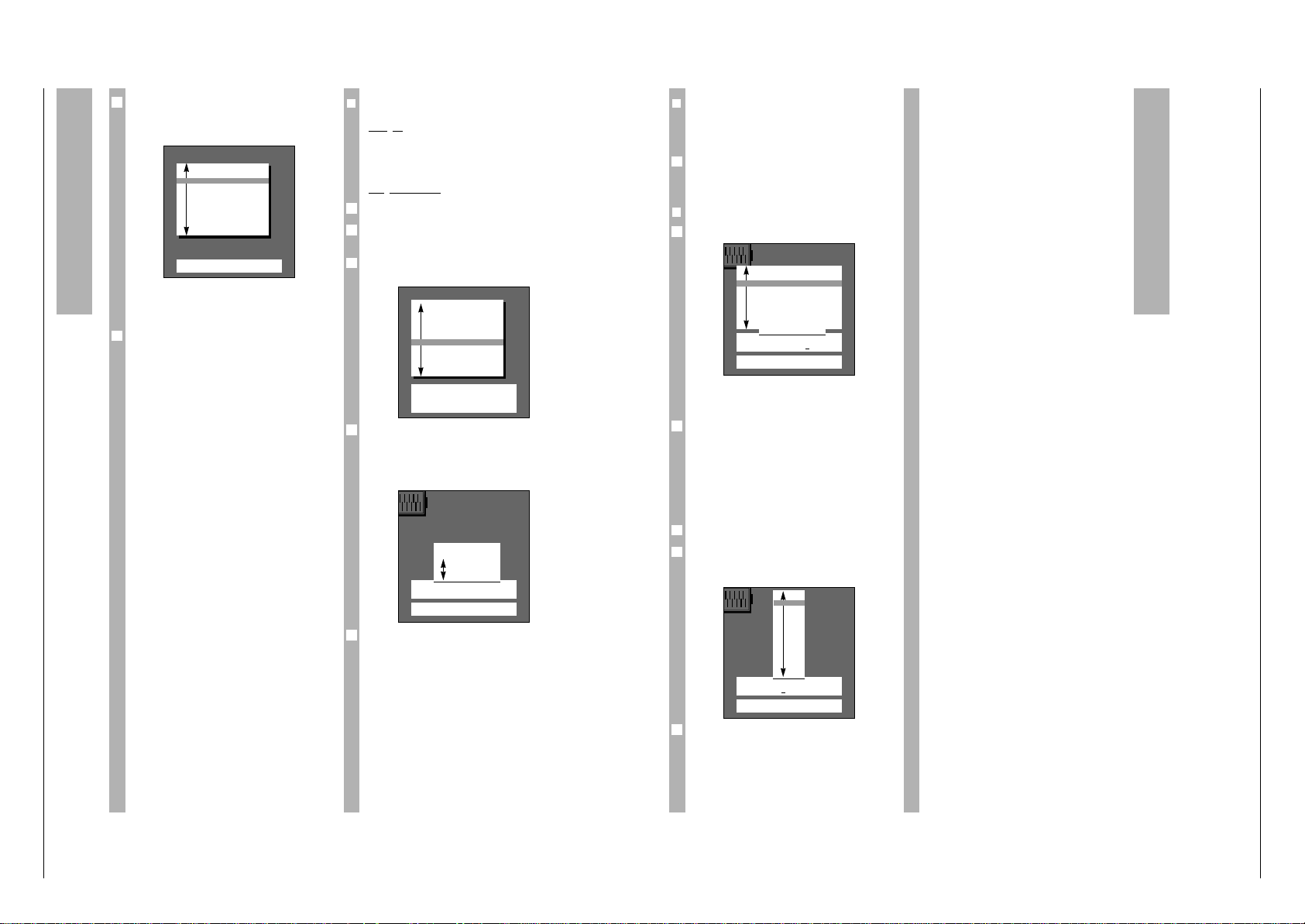
Kurzanleitung
TXT
TV-Bild
66
Dialog Center aufrufen
p
P
Auswahlbalken auf/ab
FE Einstellen von Werten
OK
Bestätigen oder Aufrufen
TXT
Zurück zum TV-Bild
Bitte warten
–
–
Alle empfangbaren Programme
werden automatisch gesucht
und in der Programm-Tabelle
gespeichert.
Empfang über:
OK
Aufrufen
TXT
TV-Bild
Kabel (Frequenzwahl in MHz)
Kabel/Antenne (Kanalwahl)
Programmplätze belegen
Wählen Sie den zu verändernden Programmplatz mit
pP an, und drücken Sie die farbige Taste für die
entsprechende Funktion (z.B. Löschen = rote Taste).
Sind alle Änderungen ausgeführt, beenden Sie mit
1
TXT
.
Drücken Sie bei den übrigen Funktionen – z.B.
Namen ändern, Kanal ändern, Programmplatz für
angeschlossenen Decoder (Decoder »ein«) vorbereiten – die in der Dialogzeile der TV-ProgrammTabelle jeweils vorgegebene farbige Taste an der
Fernbedienung.
Folgen Sie bei evtl. weiteren Änderungen den Angaben in den Dialogzeilen.
❒
ATS euro plus
Automatische Programmierung
Wenn Sie mit »ATS euro plus« bereits Programme
gefunden und gespeichert haben und einen weiteren Suchlauf starten wollen – bedingt durch veränderte Empfangsverhältnisse (z.B. Wohnortwechsel,
nachträglicher Kabelanschluß) – dann drücken Sie
die Taste h und G.
Einblendung:
1
4
3
❒
Das DIALOG CENTER
Das DIALOG CENTER ist die Steuerzentrale des
Fernsehgerätes.
Durch Drücken der Taste h und G können Sie es
aufrufen. Hier können Sie vielfältige Einstellungen
vornehmen.
Des weiteren werden auf der Seite »Kurzanleitung«
die Dialogzeichen erklärt. Sie zeigen bei jedem
Bedienschritt an, mit welchen Tasten der Fernbedienung bestimmte Funktionen ausgeführt werden
können.
P
Bewegen des farbigen Balkens nach
oben/unten.
p
Bei zweiseitigen Tabellen (z.B. TVPROGRAMM-TABELLE) wird auf die
zweite Seite »umgeblättert«.
FE Einstellen von Werten.
G Bestätigen der angewählten Funktion.
1
TXT
Zurück zum Fernsehbild.
Bei der Mehrzahl der Einblendungen werden am
unteren Bildrand Dialogzeichen angeboten. Sie sind
Wegweiser für den Dialog zwischen Ihnen – mittels
Fernbedienung – und dem Gerät.
Prüfen Sie jetzt mit welchen Programmen die Programmplätze belegt sind. Sagt Ihnen daran etwas
nicht zu, können Sie an der Programmplatzbelegung Änderungen vornehmen (z.B. an der Reihenfolge, Programmplätze löschen usw.).
Drücken Sie Taste
1
TXT
und "blättern" die Programm-
plätze mit pP durch.
❒
Änderungen an der ProgrammplatzBelegung
Eine Gesamtübersicht der Programmplatz-Belegung erhalten Sie mit der TV-Programm-Tabelle.
Rufen Sie das DIALOG CENTER mit h und G auf.
Wählen Sie mit p oder P »TV-PROGRAMM-
TABELLE« an und mit G auf.
2
1
6
6
AV
TXT
OK
P
P
TV
6
TV-PROGRAMM-TABELLE
● Namen ändern
● Verschieben
TXT
TV-Bild
● Kanal ändern
● Löschen
66
Zurück
AUX
Decoder
Prog Name Kanal Decoder
AV
■
1 ARD C 06
2 ZDF C 34
3 BR 3 C 59
4 RTL C 36
5 SAT1 C 40
6 PRO7 C 21
7 RTL2 C 53
8 PREM C 12 ein
9 –––– C 00
1
DIALOG CENTER
OK
Aufrufen
TXT
TV-Bild
■
KINDERSICHERUNG
TV-PROGRAMM-TABELLE
AUTOMATISCHE PROGRAMMIERUNG
(ATS/ACI ODER MEGALOGIC)
AUDIO-/VIDEO-ANSCHLÜSSE
SONDERFUNKTIONEN
SERVICE
Page 13
CUC 1825 / 1826 Allgemeiner Teil / General Section
GRUNDIG Service 1 - 13
Programmplätze belegen
❒
Programmplätze manuell belegen
Beis
piel
Auf Programmplatz 15 soll ein Programm gelegt
werden, das auf Sonderkanal S08 in Norm
SECAM L/L' ausgestrahlt wird.
Vorgehensweise
Programmplatz 15 wählen.
Taste h und G drücken.
Das »DIALOG CENTER« blendet sich ein.
Mit pP TV-PROGRAMM-TABELLE auswählen und
mit G einblenden.
Funktion »Kanal ändern« wählen;
hierzu Taste h drücken.
Verfahren Sie wie in den Dialogzeilen beschrieben.
In der Belegzeile ist die Zehnerposition für die
Kanaleingabe rot unterstrichen.
Für das Einstellbeispiel (Sonderkanal S 08 einstellen) drücken Sie die Taste F, dann die Tasten p
oder P.
Aus C für Kanal wird S für Sonderkanal.
Danach die Tasten E, 0und 8drücken.
5
4
3
2
1
TV-PROGRAMM-TABELLE
● Namen ändern
● Verschieben
TXT
TV-Bild
● Kanal ändern
● Löschen
66
Zurück
AUX
Decoder
Prog Name Kanal Decoder
10 TV 5 C 26
11 ARD C 06
12 ZDF C 34
13 BR 3 C 59
14 RTL C 36
■
15 SAT1 C 40
16 PRO7 C 21
17 RTL2 C 53
18 PREM C 12 ein
19 –––– C 00
PROG 15 S 08 -03 Standard
F
–
–
❙
_
■
–––
–
❙
–
–
❙
E
OK
Bestätigen
TXT
Abbrechen
0–9
Kanaleingabe
● Suchlauf
Feinabstimmung
Drücken Sie Taste p oder P bis »Automatische
Programmierung« farbig hinterlegt ist und anschließend Taste G.
Einblendung:
Sie haben die Auswahl zwischen »Neue TV-Programme suchen« oder »Komplette Neuprogrammierung«.
Benutzen Sie zur weiteren Einstellung die Hinweise
in der Dialogzeile.
w
!
Wurde »Neue TV-Programme suchen« gewählt,
entfallen die Einblendungen für Sprache und Land.
w
!
Wurde »Komplette Neuprogrammierung« gewählt,
wird eine Neubelegung vorgenommen. Die bisherigen Programmplatz-Daten werden gelöscht.
Vorgehensweise wie Seite 4.
Wenn an diesem Fernsehgerät ein Video-Recorder
mit MEGALOGIC-Funktionen angeschlossen ist (die
Verbindung muß über die EURO-AV-Buchsen –
beim Fernsehgerät Buchse AV1 – mit einem vollbeschalteten EURO-AV-Kabel hergestellt werden)
erfolgt zusätzlich im Menü die Einblendung »Übertragung Programm-Tabelle TV ®VCR«.
Übertragung Programm-Tabelle
TV ➞ VCR
Das Fernsehgerät ist mit dem MEGALOGIC-System
ausgerüstet.
Mit Video-Recordern dieses Systems bietet sich
Ihnen ein besonderer Bedienkomfort.
Sie können die programmplatzbezogenen Daten
(gespeicherte Programme) des Fernsehgerätes
dem Video-Recorder (VCR) übertragen.
Ein ATS-Suchlauf am Video-Recorder ist damit
überflüssig.
Danach kann sofort ferngesehen und vom Fernsehgerät zum Video-Recorder aufgenommen werden.
Drücken Sie hierzu Taste p oder P bis »Übertragung Programm-Tabelle« farbig hinterlegt ist und
anschließend Taste G.
Der Hinweis »Bitte warten Übertragung ProgrammTabelle TV ®VCR« wird eingeblendet.
3
2
Automatische Programmierung
OK
Aufrufen
TXT
TV-Bild
■
Neue TV-Programme suchen
Komplette Neuprogrammierung
(bei Wohnortwechsel)
Übertragung
Programm-Tabelle TV ®VCR
❒
Feinabstimmen
Bei schwierigen Empfangsverhältnissen kann es in
Einzelfällen notwendig sein, das Bild durch Feinabstimmen zu verbessern.
Hierzu dienen die Tasten pP; achten Sie dabei auf
optimale Einstellung von Bild und Ton.
Sie können von +63 bis -64 variieren.
❒
Standard (Norm) einstellen
Taste E zweimal drücken.
Der bisherigen Einblendung wird eine Liste der
Normen hinzugefügt die das Gerät empfangen und
wiedergeben kann.
Taste p oder P drücken, bis das Kürzel L/L' AM
6,5 NICAM (Standard) angewählt ist.
Das Gerät stimmt automatisch auf das beste Bild ab.
Der Vorgang – Programmplatz 15 mit S 08 in Norm
SECAM L/L' zu belegen – ist beendet.
Auch diesem Programmplatz kann eine Senderken-
nung (Kürzel) hinzugefügt werden.
Hierzu Taste G drücken.
Durch Drücken der blauen Taste ist in der Dialog-
zeile der eingeblendeten »TV-PROGRAMM-TABELLE« die Funktion »Namen ändern« zu wählen.
Mit Tasten pP passendes Kürzel wählen.
Verfahren Sie weiter wie in den Dialogzeilen angegeben.
5
4
3
2
1
1
Programmplätze belegen
PROG 15 S 08 -03 Standard
F
–
–
❙
–
–
❙
–
–
❙
■
–
–
E
OK
Bestätigen
TXT
Abbrechen
B/G FM 5.5 (A2 Stereo)
■
L/L’ AM 6.5 (NICAM)
I FM 6.0 (NICAM)
D/K/K’ FM 6.5/6, 258 (A2 Stereo)
B/G FM 5.5 (NICAM B, DK, E)
B/G FM 5.5 (NICAM N, S, SF)
D/K/K’ FM 6.5 (NICAM)
D/K/K’ FM 6.5/6, 742 (A2 Stereo)
PROG 01 –––––
F
■
–––
–
❙
–
–
❙
–
–
❙
–
–
❙
E
OK
Bestätigen
TXT
Abbrechen
■
––––
ARTE
BRT1
BRT1
CAN
+
C1
FNET
F2
F3
INFO
ITB
LIFE
1
1
1
Page 14
Allgemeiner Teil / General Section CUC 1825 / 1826
1 - 14 GRUNDIG Service
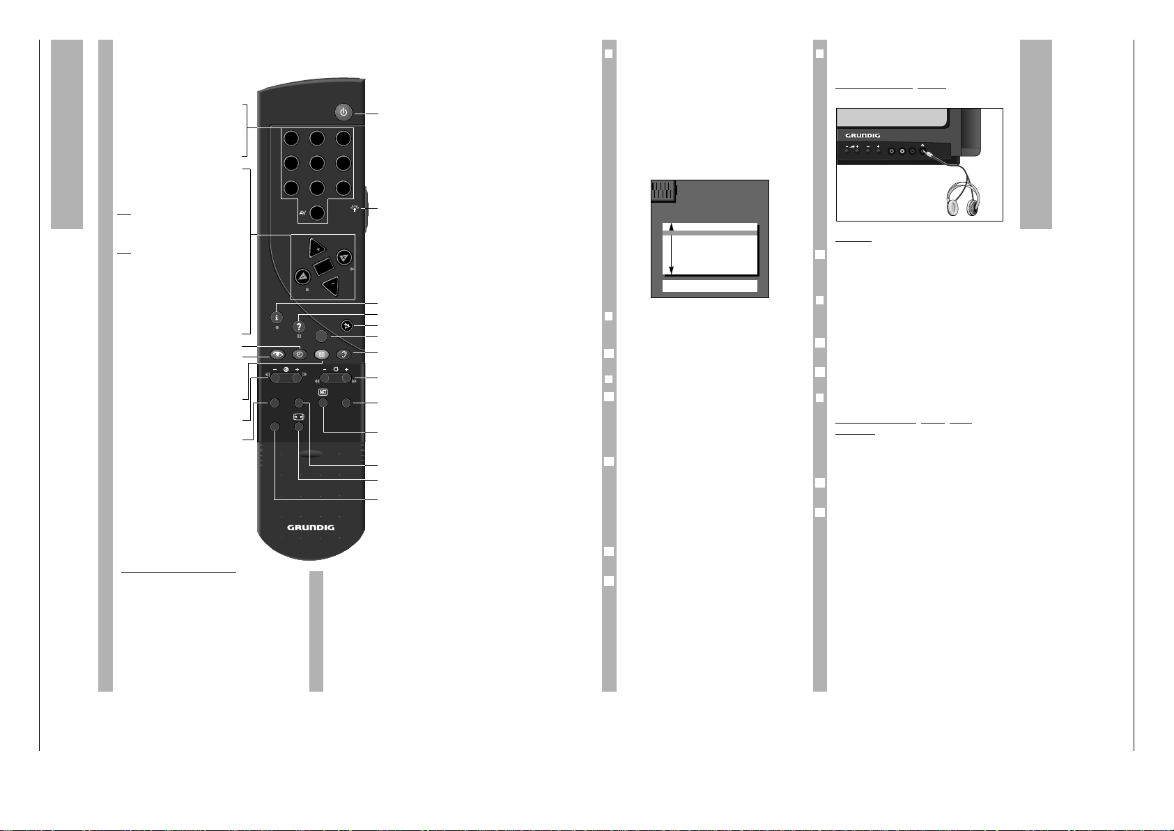
Die Fernbedienung
Auf dieser Seite sind die Tasten der Fernbedienung
nur kurz erklärt. Ausführliche Beschreibungen entnehmen Sie bitte den jeweiligen Kapiteln.
ik (Taste – E) = Bildsuchlauf rückwärts
ju (Taste E +) = Bildsuchlauf vorwärts
● (Taste h) = Aufnahmestart
■ (Taste F ) = Stop
ii (Taste –
R
) = schneller Rücklauf
uu (Taste
R
+) = schneller Vorlauf
ll ll (Taste
¢
D
) = Pause
e (Taste E) = Wiedergabestart
p = Programmplatz –
P = Programmplatz +
Video-Recorder fernbedienen
Mit der Fernbedienung dieses Fernsehgerätes können Sie auch Grundig-Video-Recorder fernbedienen. Welche hierzu geeignet sind, sagt Ihnen Ihr
Fachhändler.
Taste
¢
VIDEO drücken und gedrückt halten.
Damit schalten Sie die Fernbedienung auf VideoRecorder-Betrieb.
Anschließend die gewünschte Taste drücken.
Entnehmen Sie der folgenden Aufstellung, mit
welchen Tasten die Recorderfunktionen ausgelöst
werden können.
1…0
Programmwahl und Einschalten
AV
0
des Gerätes aus Bereitschaft
oder
– AV-Stellung wählen
– Eingeben der Seitennummern
im Videotext-Betrieb
P Einschalten des Gerätes aus
Bereitschaft. Programm schrittweise fortschalten (1, 2, 3 ...)
p Programm schrittweise
fortschalten (... 3, 2, 1)
oder
pP Cursor-Bewegung nach oben,
unten
xc
Lautstärke
oder
xc
Cursor bewegen nach links,
nach rechts.
Wird eine der Tasten P oder p gedrückt
gehalten, werden die Senderkennungen
eingeblendet und schnell durchlaufen.
Das Gerät schaltet nach Loslassen der
Taste auf den gewählten Programmplatz.
G Ändern und Aktivieren verschie-
dener Funktionen
h
Uhrzeit ein/aus.
k
Bildeinstellungen
Vorwahl zum Einstieg in das
Menü »Bildeinstellungen«
j
Standbild oder
¢
AUX und
j
ist Program scan
- E + Farbkontrast ändern.
SAT Satelliten-Receiver fernbedienen
(dazu Taste SAT gedrückt halten).
b
In Bereitschaft schalten.
R Tasten-Beleuchtung ein/aus. Die
Beleuchtung wird nach kurzer Zeit
automatisch abgeschaltet.
h Einstieg ins DIALOG CENTER
¢
D
Kurzanleitung aufrufen
¢
+ Ton ein/aus (stummschalten).
¢
TXT
Videotext/-Betrieb Ç TV-Betrieb.
g
Toneinstellungen
Vorwahl zum Einstieg in das
Menü »Toneinstellungen«
- R +
Helligkeit ändern.
AUX
Vorwahltaste für verschiedene
Funktionen, z.B.
¢
AUX und
j
ist Program scan
C
Info über die aktuelle Sendung
(siehe auch Kapitel Fernsehen "Zur
Zeit im Programm" auf Seite 16)!
PIP Bild im Bild ein/aus
E
Bildformat-Umschaltung
4:3 Ç 16:9
VIDEO Video-Recorder fernbedienen
(dazu Taste VIDEO gedrückt
halten).
TP 900
VIDEO
AUX
SAT PIP
3
21
4 5 6
7 8 9
0
P
P
TXT
OK
❒
Ton-Einstellungen
Mit Taste g können nacheinander vier verschiedene Toneinstellungen vorgenommen werden.
Nach Drücken der Taste erfolgt eine kurze Einblendung der aktuellen Funktion.
Sie können wählen zwischen: »Sprache«, »Musik«,
»Supersound« und »Persönliche Werte«.
Wählen Sie die entsprechende Funktion nach dem
Programmangebot der Sendeanstalten aus.
Um die »Persönlichen Werte« einstellen zu können,
müssen Sie die Funktion mit Taste g anwählen
und die Taste G drücken.
❒
Stereobreite
Verbreitert bei Stereo-Sendungen das Klangbild
und verbessert es bei Mono-Sendungen.
Ändern mit Taste F oder E .
❒
Ton (Stereo-/Zweiton, Mono)
Empfängt das Gerät Zweiton-Sendungen – z.B.
einen Spielfilm im Originalton auf Tonkanal B
(Mono B; bzw. NICAM B) und die synchronisierte
Fassung auf Tonkanal A (Mono A; bzw. NICAM A) –
so können Sie den von Ihnen gewünschten Tonkanal wählen.
Empfängt das Gerät Stereo-Sendungen, schaltet es
automatisch auf Stereo-Tonwiedergabe (Anzeige:
Stereo).
Bei schlechter Stereo-Ton-Empfangsqualität können Sie auf Ton »Mono« schalten (siehe Einstellbeispiel).
Einstellbeispiel: Ton von »Stereo« auf »Mono«
schalten;
Funktion »Ton« mit Tasten p oder P farbig hinterlegen.
Mit Taste E Anzeige »Mono« wählen.
2
1
6
6
1
❒
Kopfhörer
Für den Kopfhörer ist wie bei »Ton« vorzugehen.
Anschließen des Kopfhörers
Kopfhörer-Stecker 3,5 mm ø Klinke.
Bedienen
Taste
¢
AUX drücken, danach mit der Taste F oder
E die Lautstärke verändern.
Der geänderte Wert wird auf einer Skala angezeigt.
❒
Höhen, Bässe, Balance
Die Toneinstellungen lassen sich nach Ihren individuellen Wünschen korrigieren.
Mit den Tasten p oder P die Zeile »Höhen«,
»Bässe« oder »Balance« anwählen.
Ändern mit den Tasten xoder c.
❒
Lautstärke P1
Lautstärke eines Pr
ogrammplatzes
verändern
Empfangen Sie ein Programm, dessen Lautstärke
gegenüber anderen abweicht (zu laut oder zu leise),
können Sie sie anpassen.
Mit der Taste p die Position »Lautstärke«
anwählen.
Mit Taste F oder E ändern. Es wird nur die Lautstärke des momentan gewählten Programmes
verändert.
Dies gilt auch für die AV-Programmplätze.
2
1
2
1
1
VIDEO IN L – AUDIO IN – R
P
Ton ändern
Ton-Einstellungen
TXT
TV-Bild
■
Stereobreite F
+
........
E
Ton Mono
Kopfhörer Mono
Höhen
[
■
–
–
]
Bässe
[
■
–
–
]
Balance
[
■
–
–
]
Lautstärke P 1
[
■
–
–
]
1
Page 15
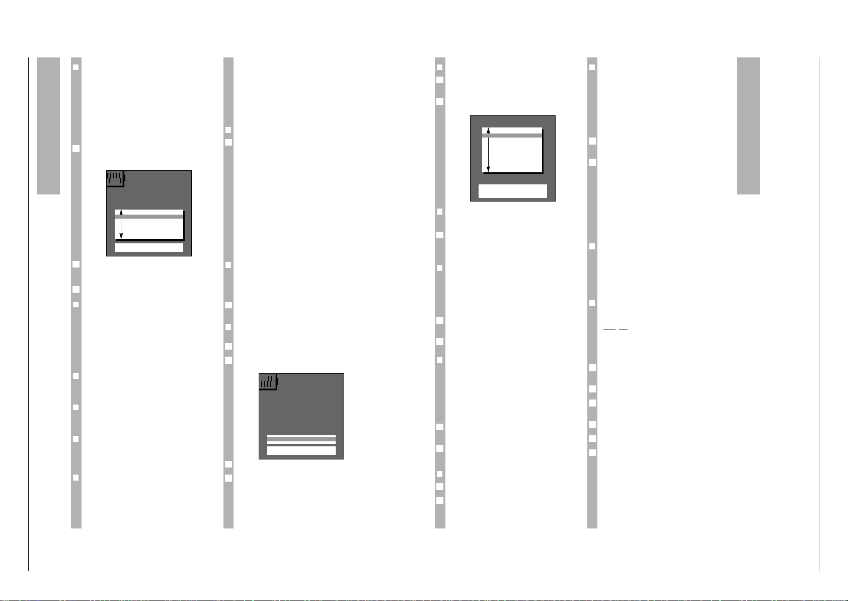
CUC 1825 / 1826 Allgemeiner Teil / General Section
GRUNDIG Service 1 - 15
Bild ändern
❒
Bild-Einstellungen
Mit Taste k (rot) können nacheinander vier
verschiedene Bildeinstellungen vorgenommen
werden. Nach Drücken der Taste erfolgt eine kurze
Einblendung der aktuellen Funktion.
Sie können wählen zwischen:
»Am Tag«, »Am Abend«, »Soft« und »Persönliche
Werte«.
Wählen Sie nach Ihren Wünschen und der Tageszeit entsprechend aus.
Um die »Persönlichen Werte« einstellen zu können,
müssen Sie mit Taste k die Funktion anwählen
und die Taste G drücken.
Mit der Taste p oder P »Kontrast«, »Bildschärfe«,
»Weißbalance«, »Perfect Clear« oder »Rauschredukt.« anwählen (farbig hinterlegen).
Ändern der Werte mit den Tasten F, E.
❒
Kontrast
w
!
Das Fernsehgerät wurde mit maximalem Kontrast
getestet, um die Zuverlässigkeit aller Baugruppen
zu prüfen.
Abhängig vom Gerätestandort und der Raumhelligkeit (Umgebungslicht) ist es jedoch sinnvoll, den
Kontrast etwas zu reduzieren um den subjektiv
besten Bildeindruck zu erhalten.
❒
Bildschärfe
Damit können Sie die Bildschärfe nach Ihren Wünschen optimal einstellen.
❒
Weißbalance
Damit können Sie den Farbton leicht rötlich oder in
einen Blauton verändern.
❒
Perfect Clear
Vergrößert den Kontrastumfang. In dunkleren Bildpartien wird der Kontrast gedehnt, das Bild gewinnt
an Tiefe und Zeichnung.
❒
Rauschreduktion
Die Rauschreduktion verbessert bei schlechten
TV/Video-Signalquellen die Bildqualität.
Weiterhin werden systembedingte Farbstörungen
(Cross-Color), die an feinen senkrechten
Schwarz/Weiß-Linien auftreten, vermindert.
3
2
1
Sie können wählen zwischen:
aus = bei guter Bildqualität
autom. = bei leicht verrauschtem Bild
stark! = sollte nur bei stark gestörtem Bild benutzt
werden, da bei schnellen Bewegungen
Nachzieh-Effekte auftreten können.
Menü ausblenden, zurück zum Bild: Taste
1
TXT
drücken.
❒
Helligkeit und Farbkontrast ändern
Dazu Minus (–) oder Plus (+) der entsprechenden
Wipp-Taste (R, E) solange drücken, bis der
gewünschte Wert erreicht ist.
Helligkeit mit der Taste – R+
Farbkontrast (Farbstärke) mit der Taste – E +
Helligkeit -
■■■■■■■■■■■■■
–
–
+
Farbstärke -
■■■■■■■■■■■■
–
–
+
Beim Drücken auf die entsprechende Taste reagiert
der farbige Balken.
Bei Sendungen in NTSC-Norm wird die Farbregelung durch »Tint« ergänzt. Zur Tintkorrektur sind
¢
AUX und
™
(je nach Wunsch, – oder +) zu
drücken.
❒
Bildformat-Umschaltung
Wird dem Fernsehgerät über Video-, CameraRecorder oder PALplus-Decoder eine aufgezeichnete PALplus-Sendung zugeführt, muß auf das Bildformat 16:9 umgeschaltet werden.
Hierzu die Taste
¢
E drücken bis die Einblendung
»16:9« erfolgt.
❒
Farbdeckung
DIALOG CENTER aufrufen:
Taste h und G drücken.
Mit p »Service« anwählen und mit Taste G aufrufen. »Farbdeckung« ist farbig hinterlegt.
Mit Taste G aufrufen.
Mit Taste F oder E die Farbdeckung ändern.
Es wird nur die Farbdeckung des momentan
gewählten Programmplatzes verändert.
4
3
2
1
1
1
Bild-Einstellungen
TXT
TV-Bild
■
Kontrast F ■■■■■■■■
–
–
E
Bildschärfe
■■■■■■■■■■
Weißbalance
[
■
–
–
]
Perfect Clear aus
Rauschredukt. P01 aus
Farbdeckung
Farbdeckung P 8 F
[
■
–
–
]
E
66
Zurück
TXT
TV-Bild
Sonderfunktionen
❒
Menü aufrufen
Tasten h und G drücken.
Das DIALOG CENTER blendet sich ein.
Mit Taste p »SONDERFUNKTIONEN« anwählen
und mit Taste G aufrufen.
❒
Dialogsprache einstellen
»Dialogsprache einstellen« ist farbig hinterlegt.
Taste G drücken.
Weitere Erklärungen in der Einblendung.
Siehe auch Seite 4 »Dialogsprache einstellen«.
❒
Öko-Netzschalter
Damit kann das Gerät so voreingestellt werden, daß
es sich – nach einer von Ihnen bestimmten Zeit
(Auswahl 1h-4h) – aus der Funktion Bereitschaft
komplett abschaltet.
Sie sparen damit Energie.
Hierzu mit Tasten p, P »Öko-Netzschalter«
anwählen.
Mit F, E gewünschte Abschaltzeit eingeben.
❒
Einschalten mit...
Wenn Sie das Gerät häufig als AV-Monitor einsetzen – z.B. zusammen mit einer Camera als Überwachungsanlage oder bei Betrieb mit einem SatellitenReceiver – kann mit dieser Funktion dem AV-Programmplatz Vorrang eingeräumt werden. D.h. nach
dem Einschalten kommt anstelle des zuletztgewählten Programmplatzes der AV-Programmplatz.
Hierzu mit Tasten p, P »Einschalten mit«
anwählen.
Mit F, E gewünschten Programmplatz auswählen.
❒
Bild-/Tonskala
Mit Taste p, P anwählen.
Mit der Taste F oder E auswählen, ob Skalenein-
blendungen – wie z.B. Lautstärke erwünscht sind.
Lautstärke
F ■■■■■■■
–
–
E
2
1
2
1
2
1
1
2
1
❒
Megalogic-Info
w
!
Mit Megalogic können Informationen vom jeweiligen Video-Recorder-Betrieb eingeblendet werden.
Unabhängig vom Fernsehbetrieb werden Sie – kurz
eingeblendet – darüber informiert, welche VideoRecorder-Funktion gerade "abläuft".
Zum Beispiel: Datenübertragung der Sendertabelle,
Wiedergabe, Aufnahme, Vorlauf usw.
Hierzu mit Tasten p,P »Megalogic-Info«
anwählen.
Mit Taste F oder E wählen, ob Einblendungen
erwünscht sind oder nicht.
Wenn kein Video-Recorder mit Megalogic-Funktionen angeschlossen ist, entfällt die Einblendung
»Megalogic-Info«.
Die Sonderfunktionen im
TV-Betrieb
❒
Standbild
Damit kann ein Bild des gerade laufenden Programmes »eingefroren« werden.
Hierzu gelbe Taste j drücken.
Erneutes Drücken der Taste beendet diese Funktion.
❒
AV-Monitor – Das Fernsehgerät als Überwachungsanlage
Beis
piel:
Sie wollen mit einer Video-Camera ein Kinderzimmer überwachen und gleichzeitig fernsehen.
Gehen Sie folgendermaßen vor:
Video-Camera an Buchse AV1 oder AV2 an-
schließen.
Fernsehgerät und Camera einschalten.
Mit der Taste AV0den entsprechenden AV-Pro-
grammplatz (mit der Camera-Wiedergabe) wählen.
Gewünschtes Fernsehprogramm wählen.
Taste
¢
PIP drücken.
Das Bild aus dem Kinderzimmer blendet sich als
Standbild (Kleinbild) ein und wird ständig aktualisiert.
Anstelle der Videocamera kann auch ein Videorecorder angeschlossen und dessen Wiedergabe eingeblendet werden.
Drücken der Taste
¢
PIP beendet die Funktion.
6
5
4
3
2
1
2
1
SONDERFUNKTIONEN
66
Zurück
OK
Aufrufen
TXT
TV-Bild
■
Dialogsprache einstellen
Öko-Netzschalter 1h
Einschalten mit Prog
Bild/Ton-Skala ein
Megalogic-Info ein
1
1
Page 16
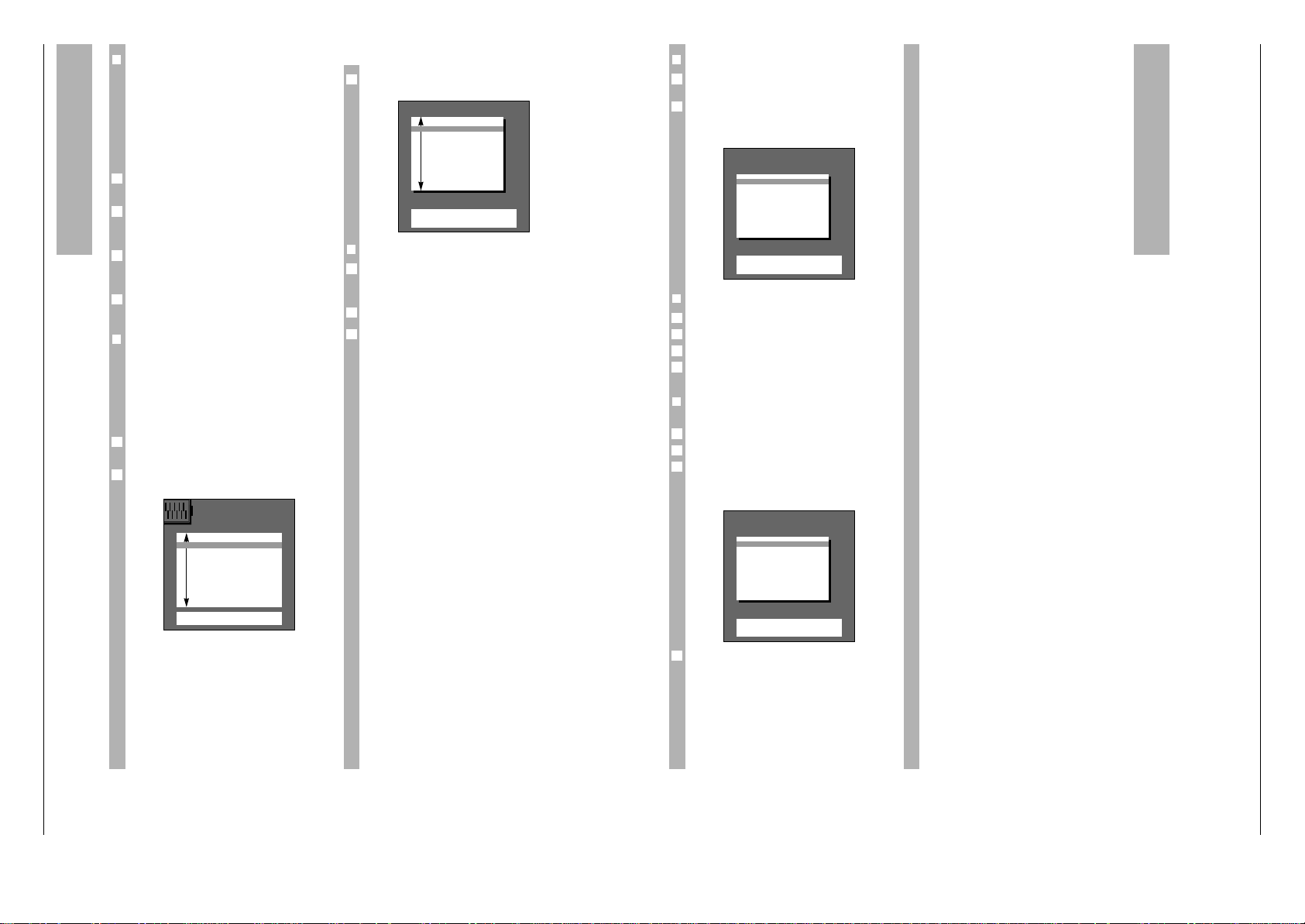
Allgemeiner Teil / General Section CUC 1825 / 1826
1 - 16 GRUNDIG Service
Komfortfunktionen
❒
Program scan
w
!
Damit können neun verschiedene Programme als
Kleinbild (als Standbild ohne Ton) im Block am
Bildschirm eingeblendet werden.
Somit erhalten Sie eine Übersicht der momentan
gesendeten Programme.
Die Bilder werden in kurzen Zeitabständen nacheinander aktualisiert.
Gehen Sie folgendermaßen vor:
Taste
¢
AUX und Taste j drücken.
Der Programmblock 1-9 baut sich nacheinander auf.
Wollen Sie aus dem Programm-Angebot eine Sen-
dung gezielt auswählen, dann drücken Sie die entsprechende Zifferntaste 1…9.
Haben Sie mehr als neun Programmplätze belegt,
dann schalten Sie mit p oder P zum nächsten
Block (z.B. Programmplatz 10-18).
Zurück zum Einzelbild: mit einer der Tasten h,
¢
D
oder
1
TXT
.
❒
Kindersicherung
Mit dieser Funktion können Sie …
… einen Sicherheits-Code (Geheimzahl) eingeben,
mit dem – entweder Kindergefährdende Sendungen gesperrt – oder alle Programme gesperrt
werden;
… eine Geräte-Ausschaltzeit eingeben.
Gehen Sie folgendermaßen vor:
Tasten h und G drücken.
Das DIALOG CENTER blendet sich ein.
Mit ]die Funktion »Kindersicherung« anwählen
(farbig hinterlegen).
2
1
4
3
2
1
Funktion »Kindersicherung« aufrufen:
Taste G drücken.
❒
Geheimzahl eingeben
Beispielsweise 1111 (immer vierstellig!);
Anzeige: xxxx.
Die Ziffern werden verdeckt eingegeben.
Danach Taste G drücken.
Bitte die gespeicherte Geheimzahl gut merken!
Falls Sie die Geheimzahl vergessen haben, hilft
Ihnen ein Schlüssel auf der letzten Seite (Umschlag) weiter.
Wählen Sie nun die gewünschte Funktion aus:
6
2
1
3
Kindersicherung
0–9
Geheimzahl eingeben
OK
Bestätigen66Zurück
■
Geheimzahl
■
––––
Kindergefährdende ja
Sendungen sperren
Alle Programme sperren nein
ab: ––:––
DIALOG CENTER
OK
Aufrufen
TXT
TV-Bild
■
KINDERSICHERUNG
TV-PROGRAMM-TABELLE
AUTOMATISCHE PROGRAMMIERUNG
(ATS/ACI ODER MEGALOGIC)
AUDIO-/VIDEO-ANSCHLÜSSE
SONDERFUNKTIONEN
SERVICE
Komfortfunktionen
❒
Kindergefährdende Sendungen sperren
Das Signal für diese Sperre wird noch nicht von
allen Programmanbietern gesendet.
Wurde die Funktion "Kindergefährdende Sendung
sperren" "ja" gewählt und danach eine entsprechende Sendung empfangen, erscheint eine Tafel mit
entsprechendem Hinweis; zum Beispiel:
❒
Alle Programme sofort sperren
Geheimzahl eingeben.
Funktion "Alle Programme sperren" "ja" wählen.
Danach Gerät ausschalten.
Nach Wiedereinschalten erfolgt nachstehende Ein-
blendung.
❒
Alle Programme zu gewünschter Zeit
sperren
Geheimzahl eingeben.
Funktion "Alle Programme sperren" "ja" wählen.
Vierstellige Ausschaltzeit eingeben; (8:45 = 08:45)
Das Gerät schaltet nach Erreichen der eingegebenen Ausschaltzeit automatisch aus und kann durch
Unbefugte nicht benutzt werden.
Das Gerät kann nur durch Eingeben der vorher
gespeicherten Geheimzahl wieder eingeschaltet
werden.
6
3
2
1
4
3
2
1
6
6
Kindersicherung
0–9
Geheimzahl eingeben
Programm wählen
Geheimzahl
■
––––
RTL gesperrt
Kindergefährdende Sendung
ÇÇ
Kindersicherung
0–9
Geheimzahl eingeben
Geheimzahl
■
––––
Alle Programme gesperrt!
1
Page 17
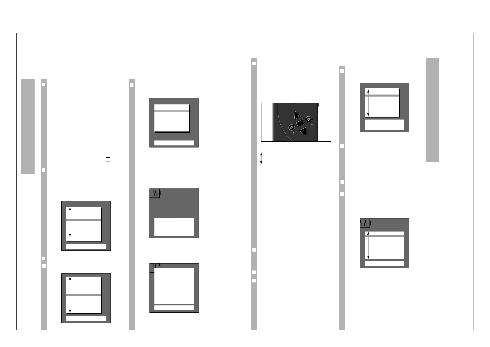
CUC 1825 / 1826 Allgemeiner Teil / General Section
GRUNDIG Service 1 - 17
❒
The station memory system
»ATS euro plus«
w
!
This unit is equipped with » ATS euro plus « (Auto
Tuning System). The automatic channel position
allocation makes this new system particularly easy
to use.
This so-called channel memory system scans the
complete reception range, stores the located channels, and enters them in a table with the respective
station names (abbreviations).
After the set has been switched on the display
»Adjust language on screen« appears.
w
!
If the page does not appear then press the h and
G buttons on the remote control one after the
other.
The DIALOG CENTER appears (see ill. page 5, on
right). Proceed as described there from .
❒
Selecting dialogue language
w
!
You can chose from a number of languages for the
dialogue between yourself and the TV set. The user
guide displays appear in the selected language.
GB is set at works. If you want to use this language,
you just have to confirm it with the G button.
❒
Selecting location (country)
Select country using |, ]and confirm with G.
This will start the search.
1
2
❒
Special information for France
If you have selected »F« for country, the following
menu is displayed.
In this menu, you can select between frequency and
channel for the ATS function using the ]button.
w
!
If you are in doubt, contact your specialized dealer.
Confirm your choice with the G button. This
starts the ATS function.
The following message will appear on the picture
screen:
w
!
The process can take a minute or longer depending
on the number of TV stations to be received.
After the search, the set switches to channel position 1 and the » Brief instructions « display appears.
Assigning Channel Positions
Adjust language on screen
OK
Confirm
TXT
TV-picture
■
D Deutsch
DK Dansk
E Espanol
F Francais
GB English
I Italiano
N Norge
NL Nederlands
P Portugues
S Svenska
SF Suomi
Select with P- button and
confirm with ok
Brief instructions
TXT
TV-picture
66
Call up Dialog Center
p
P
Option bar up/down
FE Setting values
OK
Confirm or all up
TXT
Back to TV-picture
Please wait
–
–
All receivable stations are
automatically searched and
stored in the TV programme
chart
Adjust country
OK
Confirm
TXT
TV-picture
A Austria
B Belgium
CH Switzerland
■
D Germany
DK Denmark
E Spain
F France
GB Great Britain
I Italy
N Norway
NL Netherlands
P Portugal
S Sweden
SF Finland
* Others
Reception via:
OK
Confirm
TXT
TV picture
Cable (frequency selection./MHz.)
Cable/Aerial (channel selection)
Operating Instructions Boston ST 270/8 / IDTV/LOG
Note:
This chapter contains excerpts from the operating instructions. For further particulars please refer to the
appropriate user instructions the part number of which is indicated in the relevant spare parts list.
Assigning Channel Positions
Select the channel position to be changed using
p,P and press the coloured button for the corresponding function (e.g. erase = red button).
End with
1
TXT
once all changes have been made.
For the remaining functions, press the respective
coloured button on the remote control given in the
TV station table dialogue line, e.g. change name,
change channel, prepare channel position for
connected decoder (Decoder »on«).
Follow the instructions given in the dialogue lines
for any further alterations.
❒
ATS euro plus
automatic programming
If you have already found and stored TV stations
with » ATS euro plus « and want to start a further
search – due to different reception conditions (e.g.
after moving house, with a new cable connection) –
then press the h and G buttons.
Display:
1
4
3
❒
The DIALOG CENTER
w
!
The DIALOG CENTER is the TV set’s control centre.
You can call it up by pressing the h and G but-
tons. You can carry out various adjustments there.
The dialogue symbols are also explained on the
page » Brief Instructions «. At each operating step
they show which buttons on the remote control can
be used to carry out certain functions.
P
Move the coloured bar upwards/downwards.
p
With two-page tables (e.g. TV PROGRAMME CHART) the second page is
»turned to«.
FE Set values.
G Confirm the selected function.
1
TXT
Return to television picture.
w
!
Dialogue symbols are given at the bottom of the
picture on most of the displays. They are signposts
in the dialogue between you – using the remote
control – and the set.
Now check which channel positions the stations
have been assigned to. If you are not happy with
something you can make alterations to the channel
position assignment (e.g. the order, delete channel
positions etc.).
Press the
1
TXT
button and “scroll” through the
channel positions using p,P.
❒
Alterations to the channel position
assignment
The TV Programme Chart will give you a complete
overview of the channel position assignment.
Call up the DIALOG CENTER using h and G.
Select » TV-PROGRAMME-CHART « using p or P
and call up with G.
2
1
P
P
OK
TV-PROGRAMME-CHART
● Change name
● Move
TXT
TV-picture
● Change channel
● Delete
66
Return
AUX
Decoder
Prog Name Chan. Decoder
AV
■
1 ARD C 06
2 ZDF C 34
3 BR 3 C 59
4 RTL C 36
5 SAT1 C 40
6 PRO7 C 21
7 RTL2 C 53
8 PREM C 12 on
9 –––– C 00
DIALOG CENTER
OK
Call up
TXT
TV-picture
■
PARENTAL LOCK
TV-PROGRAMME-CHART
AUTOMATIC PROGRAMMING
(ATS/ACI or MEGALOGIC)
AUDIO-/VIDEO-INPUTS
SPECIAL FUNCTIONS
SERVICE
1
1
1
Page 18
Allgemeiner Teil / General Section CUC 1825 / 1826
1 - 18 GRUNDIG Service
Assigning Channel Positions
❒
Assigning channel positions manually
Exam
ple
A TV station which is broadcast on special channel
S 08 in SECAM L/L' norm is to be allocated to channel position 15.
Procedure
Select channel position 15.
Press the h button and the G button.
The »DIALOG CENTER« appears.
Select the TV Programme Chart using p,P and
call up with G.
Select the »Change channel« function.
To do this, press the h button.
Proceed as described in the dialogue lines.
The ten position for the channel entry is underlined
in the assignment line.
In the example (setting special channel S 08) press
the F button and then the p or P buttons.
C for channel becomes S for special channel.
Afterwards press the buttons E, 0and 8.
5
4
3
2
1
TV-PROGRAMME-CHART
● Change name
● Move
TXT
TV-picture
● Change channel
● Delete
66
Return
AUX
Decoder
Prog Name Chan. Decoder
10 TV 5 C 26
11 ARD C 06
12 ZDF C 34
13 BR 3 C 59
14 RTL C 36
■
15 SAT1 C 40
16 PRO7 C 21
17 RTL2 C 53
18 PREM C 12 on
19 –––– C 00
PROG 15 S 08 -03
F
–
–
❙
_
■
–––
–
❙
–
–
❙
E
OK
Confirm
TXT
Stop cancel
0–9
Channel entry
● Search mode
Finetuning
Press the p or P button until » Automatic Programming « has a coloured background and then
press the G button.
Display:
You can chose between » Search for new TV-stations« or »Complete reprogramming«.
Use the notes in the dialogue line for further setting.
w
!
If » Search for new TV-stations « was selected, the
displays for language and country will be omitted.
w
!
If » Complete reprogramming« was selected then a
new assignment is carried out. Previous channel
position data is erased.
Proceed as on page 4.
If a video recorder with MEGALOGIC functions is
connected to this TV set (this connection must be
made via the EURO-AV sockets – on TV set socket
AV1 – using a fully allocated EURO-AV cable) then
the display » TV programme chart transfer TV
®
VCR« will also appear on the menu.
Transfer of TV Programme Chart
TV ➞ VCR
The TV set is equipped with the MEGALOGIC
system.
Using the TV set with MEGALOGIC video recorders
will mean extremely easy operation.
You can transfer the TV set channel position data
(stored TV stations) to the video recorder (VCR).
An ATS search is therefore not necessary on the
recorder.
The TV can be watched and video recordings can be
made from the TV set immediately afterwards.
To do this press the p or P button until
»Transfer of TV programme chart« has a coloured
back-ground and then press the G button.
3
2
AUTOMATIC PROGRAMMING
OK
Call up
TXT
TV-picture
■
Search for new TV-stations
Complete reprogramming
(when changing address)
Transfer of
TV programme chart TV ®VCR
Assigning Channel Positions
❒
Fine tuning
The set tunes itself automatically to the best picture.
If reception is poor, in some cases it might be
necessary to improve the picture by fine tuning.
The pP buttons are used for this. Make sure the
picture and sound are set properly.
You can vary from +63 to –64.
❒
Setting standard (norm)
Press the E button twice.
A list of the norms that the set can receive and
show is added to the previous display.
Press the p or P button until the abbreviation L/L'
AM 6,5 NICAM (Standard) is selected.
The set will automatically tune to the best picture.
The procedure – assigning channel position 15 with
S 08 in SECAM L/L' norm – is completed.
A station identification (abbreviation) can also be
added to this channel position.
To do this press the G button.
The function »Change name« in the dialogue line of
the » TV PROGRAMME CHART « display is to be
selected by pressing the blue button.
Select the correct abbreviation using the pP buttons.
Continue as indicated in the dialogue line.
5
4
3
2
1
1
PROG 01 –––––
f
■
–––
–
❙
–
–
❙
–
–
❙
–
–
❙
d
OK
Confirm
TV
Stop/Cancel
■
––––
ARTE
BRT1
BRT1
CAN
+
C1
FNET
F2
F3
INFO
ITB
LIFE
PROG 15 S 08 -03 Standard
f
–
–
❙
–
–
❙
–
–
❙
■
–
–
d
OK
Confirm
TXT
Stop/Cancel
B/G FM 5.5 (A2 Stereo)
■
L/L’ AM 6.5 (NICAM)
I FM 6.0 (NICAM)
D/K/K’ FM 6.5/6, 258 (A2 Stereo)
B/G FM 5.5 (NICAM B, DK, E)
B/G FM 5.5 (NICAM N, S, SF)
D/K/K’ FM 6.5 (NICAM)
D/K/K’ FM 6.5/6, 742 (A2 Stereo)
1
1
1
Page 19
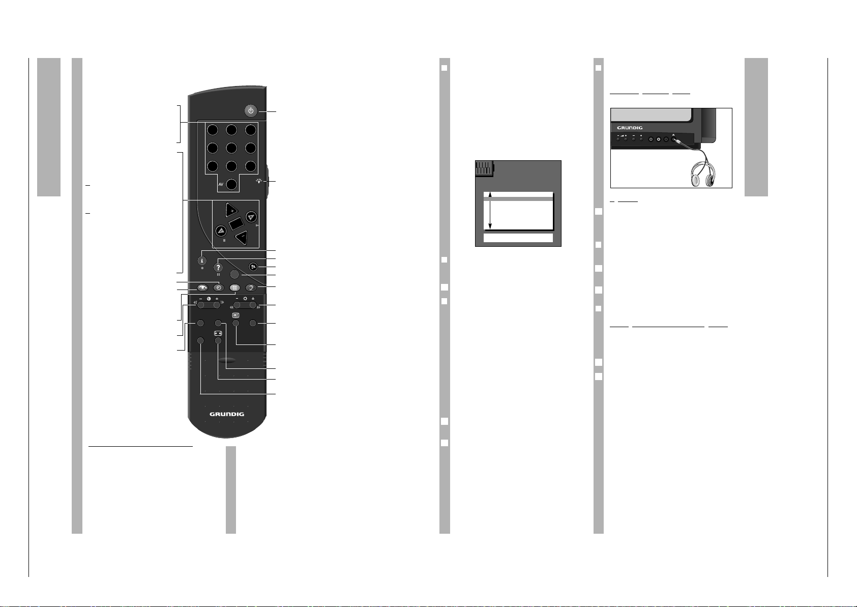
CUC 1825 / 1826 Allgemeiner Teil / General Section
GRUNDIG Service 1 - 19
The Remote Control
On this page, the buttons on the remote control are
briefly explained. For detailled information see the
corresponding chapters in this booklet.
ik ( – E button) = Reverse picture search
ju (E + button) = Forward picture search
● (h button) = Start recording
■ ( F button) = Stop
ii ( –
R
button) = Fast rewind
uu (
R
+ button) = Fast forward wind
ll ll (
¢
D
button) = Pause
e (E button) = Start playback
p = Programme position –
P = Programme position +
Remote Control of a Video Recorder
The remote control handset of your TV set enables
also the remote control of Grundig video recorders.
Your specialized dealer can tell you which video
recorders are suited for this.
Press and hold down the
¢
VIDEO button.
This switches the remote control handset into the
video recorder mode.
Then press the desired function button.
The following table shows you which buttons are to
be used for the various recorder functions..
1…0
Select programme and switch
0
AV on from standby,
or
– select AV position,
– enter page numbers in Teletext
mode.
P Switch on from standby. Select
programmes step by step
(1, 2, 3 ...)
p Select programmes step by step
(... 3, 2, 1)
or
pP Move cursor up and down.
xc
Volume
or
xc
Move cursor to the left and
right.
When holding down the P or p button,
the station names will scroll on the screen. When releasing the pressed button,
the TV set switches to the selected programme position.
G Modify and activate certain
functions.
h
Time display on/off.
k
Picture adjustments.
Access to the »Picture settings«
menu.
j
Still picture, or
¢
AUX plus
j
= Program scan
- E + Colour contrast.
SAT Satellite receiver remote control
(press and hold down the SAT
button).
b
Switch to standby.
R Button illumination on/off. After a
few moments, the illumination is
switched off automatically.
h Access to the DIALOG CENTER
¢
D
Call up brief instructions.
¢
+ Sound on/off (mute).
¢
TXT
Teletext mode Ç TV mode
g
Sound adjustments.
Access to the »Sound settings«
menu.
- R +
Brightness
AUX
Preselect button for certain functions, e.g.
¢
AUX plus
j
= Program scan
C
Info about current broadcast
(see chapter »Current TV
programme« on page 16).
PIP Picture-in picture on/off.
E
Picture format switching
4:3 Ç 16:9
VIDEO Video recorder remote control
(press and hold down the
VIDEO button).
TP 900
VIDEO
AUX
SAT PIP
3
21
4 5 6
7 8 9
0
P
P
TXT
OK
❒
Sound adjustments
Four different sound adjustments can be made one
after the other using the g button. The current
functions are briefly displayed after the button is
pressed.
You can chose between: » Language «, » Music «,
»Supersound« and » Personal«.
Select the corresponding function according to the
broadcasters TV programme offer.
To be able to set the »Personal«, you have to select
the function using the g button and press the
G button.
❒
Stereo expansion
Deepens the acoustic pattern with stereo broadcasts and improves it with mono broadcasts.
Alter using the F or E button.
❒
Sound (Stereo/two-channel, mono)
w
!
If the set receives two-channel broadcasts – e.g.
the original version of a film on sound channel B
(Mono B) and the dubbed version on sound channel A (Mono A) – then you can choose the sound
channel you prefer (Display indicators: Mono).
w
!
If the set receives stereo broadcasts, it will automatically switch to stereo sound reproduction (Display
indicators: Stereo).
If the stereo sound reception is poor then you can
switch the sound to » Mono « (see adjustment
example).
Adjustment example: switching sound from
»Stereo« to »Mono«;
Give the » Sound « function a coloured background
using the p or P buttons.
Select the display »Mono« using the E button.
2
1
1
❒
Headphones
For headphones proceed as with »Sound«.
Connecting the headphones
Headphone plug 3.5 mm diameter jack.
Operation
Press the
¢
AUX button and then alter the volume
using the F or E button.
The altered value is shown on a scale.
❒
Treble, Bass, Balance
The sound setting can be altered as you wish.
Select the line » Treble «, » Bass « or » Balance «
using the p or P buttons.
Alter using the F or E button.
❒
Volume P1
Alterin
g the volume of a channel position
If you receive a station whose volume differs from
others (too loud or too quiet), then you can change
this.
Select the » Volume « position using the p button.
Alter using the F or E button. Only the volume of
the station currently selected is altered.
This also applies for the AV channel positions.
2
1
2
1
1
VIDEO IN L – AUDIO IN – R
P
Altering Sound Settings
Sound -settings
TXT
TV-picture
■
Stereo expan
+
........
Sound Mono
Headphones
[
■
–
–
]
Treble
[
■
–
–
]
Bass
[
■
–
–
]
Balance
[
■
–
–
]
Volume P 1
[
■
–
–
]
1
Page 20
Allgemeiner Teil / General Section CUC 1825 / 1826
1 - 20 GRUNDIG Service
Adjusting Picture
❒
Picture adjustments
Using the k button four different picture adjustments can be made one after the other. The current
functions are displayed briefly after the button is
pressed.
You can choose between:
»During the day«, » In the evening«, »Soft« and »
Personal«.
Select according to your desires and the time of
day.
To be able to set the » Personal « you have select
the function using the k button and press the
G button.
Select »Contrast «, »Sharpness«, »White balance«,
» Perfect Clear « or » Noise reduct. « using the
p or P button (give it a coloured background).
Alter the values using the F, E buttons.
❒
Contrast
w
!
The TV set was tested with maximum contrast in
order to test the reliability of all components.
Depending on where the set is placed and the
brightness of the room (ambient light), it is a good
idea to reduce the contrast slightly in order to get
the subjectively best picture.
❒
Sharpness
You can use this to set the picture definition optimally according to your desires.
❒
White balance (Blue stretch)
You can use this to give the colour a slight red or
blue tint.
❒
Perfect Clear
Increases the contrast range. The contrast is reduced in the dark areas of the picture giving the picture depth and definition.
❒
Noise reduction
The noise reduction improves the picture quality
with poor TV/video signal sources.
3
2
1
You can chose between:
off = for good picture quality
autom. = for picture with slight interference
strong! = should only be used for a picture with a
lot of interference as tracers can appear
when there are quick movements o the
screen.
Press the
1
TXT
button to close menu and return to
picture
❒
Altering brightness and colour contrast
To do this press the minus (–) or plus (+) on the
corresponding rocker button (R, E) as long as it
takes to reach the desired value.
Brightness with the – R+button.
Colour contrast (colour) with the – E + button.
Brightness
-
■■■■■■■■■■■■■
–
–
+
Colour
-
■■■■■■■■■■■■
–
–
+
The coloured bar reacts when the corresponding
button is pressed.
In the case of broadcasts in NTSC norm, «Tint» is
added to the menu options. To adjust the Tint,
press the
¢
AUX and then the
™
button (– or +
according to your preferences).
❒
Picture format switching
If the TV set receives a recorded PALplus broadcast
via a video recorder, camcorder or PALplus decoder, the picture format must be switched to 16:9.
For this, press the
¢
E button until »16:9« is dis-
played.
❒
Colour match
Call up DIALOG CENTER:
Press the h and G buttons.
Select » SERVICE « using p and call up with the
G button. » Colour match « has a coloured
background.
Call up using the G button.
Alter the colour registration using the F or E
button.
Only the colour registration of the channel position
currently selected is altered.
4
3
2
1
1
1
Picture settings
TXT
TV-picture
■
Contrast F ■■■■■■■■
–
–
E
Sharpness
■■■■■■■■■■
White bal.
[
■
–
–
]
Perfect Clear off
Noise reduc.. off
Colour match
Colour match P 8 F
[
■
–
–
]
E
66
Return
TXT
TV-picture
Special Functions
❒
Call up menu
Press h and G buttons.
The DIALOG CENTER appears.
Select » SPECIAL FUNCTIONS « using the p
button and call up with the G button.
❒
Setting dialogue language
»Adjust language on screen« has a coloured background.
Press the G button.
Further explanations are on the display.
See also page 4 »Setting dialogue language«.
❒
Mains economy switch
Here, the unit can be set so that it switches off
completely from stand-by after a given interval
(range 1 hour to 4 hours).
This saves energy.
To do this, select » Mains economy switch « with
the p, P button.
Use F, E to enter the desired switching off interval.
❒
Switching on with...
If you often use the set as an AV monitor, for
example together with a camera as a monitoring
system or when it is used with a satellite receiver,
you can use this function to give the AV channel
position priority. i.e. when you switch on the AV
channel position appears instead of the channel
position last selected.
To do this select »Switch on with« using the p, P
buttons.
Select the desired channel position using F, E.
❒
Picture/sound options
Select using the p, P button.
Use the F or E button to select whether scale dis-
plays – such as volume are desired.
Volume
F ■■■■■■■
–
–
E
2
1
2
1
2
1
1
2
1
❒
Megalogic info
w
!
Megalogic can be used to display information on
current video recorder operation.
You are informed briefly independent of TV operation which video recorder function is » running « at
the moment.
For example: Data transfer of TV Programme Chart,
playback, recording, fast forward etc.
To do this, select » Megalogic-Info « using the
p,P buttons.
Use the F or E button to choose whether displays
are wanted or not.
If a video recorder with Megalogic functions is not
connected then the » Megalogic-Info « display will
be omitted.
The special functions in
TV operation
❒
Still picture
This can be used to » freeze « a picture from a currently running programme.
To do this press the j button.
Pressing the button again ends this function.
❒
AV Monitor – Using the TV set as a monitoring system
Exam
ple:
You want to monitor a children’s room with a video
camera and watch television at the same time.
Proceed as follows:
Connect the video camera to socket AV1 or AV2.
Switch on the TV set and the camera.
Select the corresponding AV channel position (with
the camera playback) using the AV0button.
Select desired TV station.
Press the
¢
PIP button.
w
!
The picture from the children’s room is displayed
as a stationary picture (micro-picture) and is constantly updated.
A video recorder can also be connected instead of
the video camera and its playback be displayed.
Press the
¢
PIP button to end the function.
5
4
3
2
1
2
1
SPECIAL FUNCTIONS
66
Return
OK
Call up
TXT
TV-picture
■
Adjust language on screen
Mains economy sw. 1h
Switch on with Prog.
Pic./sound options On
Megalogic-Info On
1
1
Page 21

CUC 1825 / 1826 Allgemeiner Teil / General Section
GRUNDIG Service 1 - 21
Convenience Functions
❒
Program scan
w
!
This can be used to display nine different stations
as micro-pictures (as still pictures without sound)
in a block on the screen.
This gives you an overview of the programmes currently being broadcast.
The pictures are updated in short time intervals one
after the other.
Proceed as follows:
Press the
¢
AUX and j buttons.
The station block 1–9 is set up gradually.
If you want to select one particular broadcast from
block, then press the corresponding numbered
button 1…9.
If you have more than 9 assigned channel positions
then use p or P to switch to the next block (e.g.
channel positions 10-18).
To return to the single picture, press the h,
¢
D
or
1
TXT
button.
❒
Parental lock
With this function you can …
… enter a safety code (code number) which blocks
either programmes that are unsuitable for children or which blocks all stations;
… enter a TV set switching off time.
Proceed as follows
Press the h and G buttons.
The DIALOG CENTER will appear.
Select the function » PARENTAL LOCK « using
]
(give it a coloured background).
2
1
4
3
2
1
Call up the »Parental lock« function:
Press the G button.
❒
Entering code number
For example 1111 (always four-digit!);
Display: xxxx.
The numbers are hidden when entered.
Then press the G button.
w
!
Please remember the code number well!
If you forget the code number, a key on the last
page (cover) will help you.
Now select the desired function.
2
1
3
PARENTAL LOCK
0–9
Insert code number
OK
Confirm
66
Return
■
Code number
■
––––
Lock programme no
unfit for children
All programmes blocked no
from: ––:––
DIALOG CENTER
OK
Call up
TXT
TV-picture
■
PARENTAL LOCK
TV-PROGRAMME-CHART
AUTOMATIC PROGRAMMING
(ATS/ACI or MEGALOGIC)
AUDIO-/VIDEO-INPUTS
SPECIAL FUNCTIONS
SERVICE
Convenience Functions
❒
Blocking programmes which are unsuitable for children.
w
!
The signal to block programmes is not yet broadcast by all TV stations.
w
!
If a programme which is unsuitable for children is
broadcast then a table with a corresponding message appears, for example:
❒❒
Blocking all channels at once
Enter code number.
Select »All programmes blocked yes«.
Switch off the set.
When switching the set on again, the following
message will be displayed.
Blocking all channels at a desired time
Enter code number.
Select »All programmes blocked from --:--«.
Enter a four-digit switching off time; (8:45 = 08:45)
The set switches off automatically once the entered
time is reached and cannot be used by unauthorised people.
w
!
The set an only be switched on again by entering
the previously stored code number.
3
2
1
4
3
2
1
PARENTAL LOCK
0–9
Insert code number
Programme selection
Code number
■
––––
RTL blocked
Program unfit for children
ÇÇ
PARENTAL LOCK
0–9
Insert code number
Code number
■
––––
All stations blockes!
1
Page 22

Allgemeiner Teil / General Section CUC 1825 / 1826
Service- und Sonderfunktionen
1. Einschaltfunktionen
1.1 ATS-Reset
Netzschalter "EIN" mit gedrückter Nahbedientaste "L+".
- Gerät wird mit Grundwerten geladen
a) entweder Optimal-Analogwerte der Fertigung oder
b) Analogwerte aus dem EPROM IC80060
- ATS-Bit wird gesetzt. Diese Option löst beim nächsten Einschalten
das ATS europlus aus. Die bisherige Programmbelegung (Senderkanäle) wird gelöscht.
1.2 ATS Start
Im Menü –> "Dialogsprache" –> "Gerätestandort" einstellen –> Taste
"OK" drücken, das Auto Tuning System (ATS) startet.
Der ATS sucht mit aufsteigender Frequenz, angezeigt wird der Kanal.
Bei der Ländereinstellung F und *übrige kann wahlweise auf Kanaloder Frequenzanzeige umgeschaltet werden.
Das ATS-System ermittelt das ATS-Signal oder das ACI-Signal für die
Senderkennung.
Wird ein ACI-Sender gefunden, bricht der ATS-Suchlauf ab und die
ACI-Daten werden übernommen und in der Programmtabelle gespeichert. Beim Wechsel von ATS auf ACI ist für 30sec ein ACI-Abbruch
möglich (zurück zu ATS).
Tastendruck "TXT" bricht den ATS-Lauf ab ohne zu speichern.
Weiterhin wird für die Programme 1…99 der Lautstärkeoffset zurückgesetzt und die Grundwerte für "Lumadelay" und "Peaking", sowie das
länderbezogene Peribit vorbelegt.
1.3 Mittelwerte / Notdatensatz laden (ROM-Daten)
Dies ist nur einmal nach NVM- oder µP-Wechsel möglich.
Nach Austausch des IC80065/IC80070 (NVM) muß das Gerät mit dem
Notdatensatz gestartet werden.
Nahbedientaste "P-" gedrückt halten und das Gerät mit dem Netzschalter einschalten.
Durch diesen Vorgang werden die nachfolgenden Daten aus dem
EPROM IC 80060 in die NVMs IC80065/IC80070 kopiert:
IC80070: (gerätespezifische Daten, über das Dialog Center einstellbar)
- Weißabgleich
- Bildrohrgröße
- Bildgeometrie
IC80065: (Sonderfunktionen, über das Dialog Center einstellbar)
- Analogwerte
- Gerätebezogene Zwangseinstellungen
- TV set up (Einschalten mit Programm / AV, Frequenz-, Kanalmode)
- Analog-Mittelwerte
- Kindersicherung aus
1.4 Service - Mode Programm (zur Fehlersuche im I2C-Bus)
Diese Fehlermeldungen beziehen sich nur auf Störungen im I2C-Bus,
also auf Bausteine oder Schaltkreise bei denen keine Rückmeldung
(Acknowledge) über den I2C-Bus erfolgt. Beispielsweise keine Betriebsspannung am Baustein, Unterbrechung der Leiterbahn oder I2CSchnittstelle defekt.
1.4.1 I2C-Bus, IC Test
In diesem Fehlersuchprogramm fragt der Mikroprozessor CIC80050
die am I2C Bus angeschlossenen Bausteine oder Schaltkreise ab und
zeigt sie als auszählbare Impulsfolge am Oszilloskop an (siehe Abb).
1. Zweistrahl-Oszilloskop am I2C Bus anschließen, Triggerung des
Oszilloskops auf "SCL".
2. Nahbedientaste P+ gedrückt halten und das Gerät mit dem Netzschalter einschalten.
Die Anzahl der Datenimpulse zeigt den defekten Baustein lt. Tabelle
an.
Mit der Nahbedientaste "L+" können evtl. weitere fehlerhafte Schnittstellen ermittelt werden.
Liegt kein Fehler in der I2C-Bus-Kommunikation vor, lassen sich die
Impulse SDA und SCL am Bildschirm nicht synchronisieren.
Service and Special Functions
1. Switching-on Options
1.1 ATS Reset
Press and hold button "L+" on the TV and switch the mains button "ON".
- Default values are loaded
a) either the optimum analog values stored in the factory or
b) analog values read out from the EPROM IC80060
- ATS bit is set. This option starts the ATS europlus function the next
time the TV is switched on. The previous programme allocations
(channels) are cleared.
1.2 ATS Start
In the menu –> "Adjust language on screen" –> "Adjust country" –>
press the "OK" button, the Auto Tuning System (ATS) starts.
The ATS system scans the frequencies in upward direction, indicating
the channel.
When setting the country F and *others, the display mode can be
changed optionally to indicate either the channel or the frequency.
The ATS system determines the ATS signal or ACI signal for the station
identification.
When finding an ACI station, ATS search is stopped, the ACI data are
taken over and entered into the station table. When changing from ATS
to ACI it is possible during a period of 30sec to stop the ACI function
(back to ATS).
Pressing the "TXT" button stops the ATS function without storing any data.
Additionally, for the programmes 1...99, the volume offset is reset and
the default values for "Lumadelay" and "Peaking" are stored together
with the Peri-bit for the respective country.
1.3 Loading the Average Values / Emergency Data Set (ROM Data)
This is only possible once on replacement of the NVM or µP.
After replacement of IC80065/IC80070 (NVM) the TV must be started
with the emergency data set.
Press and hold the "P-" button on the TV and switch on with the mains
button.
In doing so, the following data is read out from EPROM IC 80060 and
loaded into the non-volatile memories IC80065/IC80070:
IC80070: (specific TV data, can be set via the Dialog Center):
- white balance
- size of picture tube
- picture geometry
IC80065: (special functions, can be set via the Dialog Center)
- analog values
- customised forced settings
- TV set-up (switching on with programme/AV, frequency mode,
channel mode)
- analog average values
- electronic programme lock off
1.4 Service Mode Programme (for fault finding in the I2C bus)
These error messages refer only to interferences in the I2C bus, that is
to those modules or integrated circuits which do not return an Acknowledge bit via the I2C bus, for example to indicate that there is no
operating voltage present on the module, that there is a break in the
circuit path or that the I2C interface is defective.
1.4.1 I2C Bus, IC Test
In this fault finding programme, the microprocessor CIC80050 scans
the individual modules or integrated circuits connected to the I2C bus
and indicates them on the oscilloscope as a countable pulse sequence
(see figure).
1. Connect a double-beam oscilloscope to the I2C bus, trigger "SCL" on
the oscilloscope.
2. Press and hold "P +" on the local keyboard and switch on with the
mains button.
The number of data pulses indicates the defective module as shown
in the table.
With button "L+" on the local keyboard it is possible to find out further
defective interfaces.
If there is no fault in the I2C Bus communication the pulses SDA and
SCL cannot be synchronised on the screen.
GRUNDIG Service1 - 22
Page 23

CUC 1825 / 1826 Allgemeiner Teil / General Section
Schnitt- Anzahl fehlerhafter
stelle der Clocks Baustein/ Schaltkreis
S-DDC 1 IC1410, Feature-Box
MSC 2 IC1650, Feature-Box
CSG 3 IC1430, Feature-Box
Tuner (SAT oder terr.) 5 CIC2161, Signal-Baustein
NVM 24C08 8-11 IC 80065, Chassis
NVM 24W02 12 IC 80070, Chassis
PP 13 IC1600, Feature-Box
DP 14 IC1640, Feature-Box
RGB Prozessor 15 IC34510, Chassis
Video Prozessor 16 IC34020, Chassis
Video Matrix 17 IC43080, Chassis
Audio Prozessor 18 IC32300, Chassis
100µs
SDA
12n 1
100µs
100µs
SCL
100µs
10ms
Interface Number Defective
of Clocks Module / Integrated Circuit
S-DDC 1 IC1410, Feature-Box
MSC 2 IC1650, Feature-Box
CSG 3 IC1430, Feature-Box
Tuner (SAT or terr.) 5 CIC2161, Signal-Module
NVM 24C08 8-11 IC 80065, Chassis
NVM 24W02 12 IC 80070, Chassis
PP 13 IC1600, Feature-Box
DP 14 IC1640, Feature-Box
RGB Processor 15 IC34510, Chassis
Video Processor 16 IC34020, Chassis
Video Matrix 17 IC43080, Chassis
Audio Processor 18 IC32300, Chassis
1.5 Programmsperre (Kindersicherung)
Die Tastenfolge 3 4 2 1 hebt die persönliche Kennzahl auf.
1.6 EPROM-Versionsnummer
Mit Taste "6" das Menü "Dialog Center" –> OK aufrufen. Taste "AUX"
zeigt die Versionsnummer an. Der Index 01 in der Sachnummer
(19798-300.01) ergibt den EPROM-Stand.
2. Sonderfunktionen im Dialog Center
2.1 Öko-Netzschalter aktivieren bzw. deaktivieren
Mit Taste "6" das Menü "Öko-Netzschalter" über "Dialog Center" –>
"Sonderfunktionen" aufrufen. Mit den Tasten 3 4 auf "aus" oder
"1h…4h" stellen.
Bei aktiviertem "Öko-Netzschalter" trennt der Netzschalter das Gerät
durch zweimaligen Tastendruck der Taste 8 vom Netz.
2.2 Einschalten mit Programm "1" oder "AV"
Mit Taste "6" das Menü "Einschalten mit" über "Dialog Center" –>
"Sonderfunktionen" aufrufen. Mit den Tasten 3 4 auf "Progr" oder
"AV" stellen.
2.3 "Bild/Ton-Skala" ein oder aus für alle Programme
Mit Taste "6" das Menü "Bild-/Ton-Skala" über "Dialog Center" –>
"Sonderfunktionen" aufrufen. Bei "aus" erscheinen keine Balkenanzeigen für die Analogwerte.
3. Service-Einstellungen im Dialog Center
3.1 Blauen Bildschirmhintergrund abschalten
Mit Taste "6" das Menü "Für den Fachhandel" über "Dialog Center" –>
"Service" –> Kennzahl 8500 –> aufrufen. Gelbe Taste drücken. Nach
der Programmumschaltung ist der blaue Hintergrund abgeschaltet
und an IC 34020-(30) der Farbträgeroszillator mit ca. 200mV meßbar.
Mit Ausschalten des Gerätes wird diese Funktion wieder aufgehoben.
3.2 Farbdeckung
Mit Taste "6" das Menü "Farbdeckung" über "Dialog Center" –>
"Service" aufrufen. Mit den Tasten 3 4 wird die Farbdeckung (LumaDelay) programmplatzbezogen eingestellt.
3.3 Rauschreduktion
Mit Taste "6" das Menü "Rauschreduktion" über "Dialog Center" –>
"Service" aufrufen. Mit den Tasten 3 4 können Sie die Rauschreduktion für die Programme 1…99 auf "aus" oder "automatisch"
stellen.
1.5 Parental Lock (electronic programme lock)
To cancel your personal code number press the buttons 3 4
in this order.
1.6 EPROM Version Number
Press button "6" to call up the "Dialog Center" –> OK. The version
number is shown by pressing the "AUX" button. The index 01 of the part
number (19798-300.01) indicates the EPROM version.
2 12 1
2 1
2 12 1
2. Special Functions in the Dialog Center
2.1 Activating or Disactivating the Mains Economy Switch
Reach the "Mains economy sw." menu with button "6" via "Dialog
Center" –> "Special functions". With the buttons 3 4 select "off" or
"1h…4h".
On activation of "Mains economy sw." the mains switch disconnects
the TV from the mains by pressing the button 8 twice.
2.2 Switching on with Programme "1" or "AV"
Reach "Switch on with" menu with button "6" via "Dialog Center" –>
"Special functions". With the buttons 3 4 select "Progr" or "AV".
2.3 Picture/Sound Options On or Off for all Programmes
Reach this menu via "Dialog Center" –> "Special Ffunctions" by pressing
button"6". When selecting "off" the scales indicating the analog values do
not appear.
3. Service Settings in the Dialog Center
3.1 Switch off blue background of screen
Reach the "for authorised dealer" menu via "Dialog Center "–> "Service" –> Code Number 8500 pressing button "6". Press yellow button.
After switching over the programme, the blue background is switched
off and the colour carrier oscillator of approx. 200mV can be measured
at IC 34020-(30).
Switching off the set cancels this function.
3.2 Colour Match
Reach the "Colour match" menu via "Dialog Center" –> "Service"
pressing button "6" . With the buttons 3 4 the luma delay is set on a
per-programme basis.
3.3 Noise Reduction
Reach the "Noise reduct." menu via "Dialog Center" –> "Service"
pressing button "6". With the buttons 3 4 the noise reduction can be
set to "Off" or "Auto" for all of the programmes 1...99.
GRUNDIG Service
1 - 23
Page 24

Allgemeiner Teil / General Section CUC 1825 / 1826
3.4 IR-Dataprogrammer
Mit Taste "6" das Menü "IR-Dataprogrammer" über "Dialog Center" –>
"Service" aufrufen. Mit der Taste "OK" können mit dem IR-Dataprogrammer 2 max. 99 Programmplätze mit Daten für Kanal, Norm, Peri,
4-stellige Sendereinblendung, Finetuning-Mitte und Lautstärke-Offset
"0" abgespeichert werden.
Der Programmer AP überträgt nur Kanäle und die 4-stelligen Senderkennzeichen mit Finetuning Mitte und Lautstärke-Offset "0".
Achtung: Die Datenübertragung kann durch Störfelder elektrischer
Beleuchtungskörper beeinflußt werden.
3.5 AFC-Referenz
Sender mit genormtem Kanalraster ohne Finetuning im Band 1 einspeisen. Mit Taste "6" das Menü "AFC-Referenz" über "Dialog Center"–> "Service" –> "Für den Fachhandel" –> Kennzahl 8500 –>
aufrufen. Nach Tastendruck "OK" erscheint der automatisch ermittelte
AFC-Wert (Siehe Abgleich Kap. 1.3).
3.6 Weißabgleich
Mit Taste "6" das Menü "Weißabgleich" über "Dialog Center"–> "Service" –> "Für den Fachhandel" –> Kennzahl 8500 –> aufrufen. Mit den
Tasten 3 4 ist der Wert für "grün" und "blau" einstellbar (Siehe
Abgleich Kap. 1.6).
3.7 Bottom flutter gate
Mit Taste "6" das Menü "Bottom flutter gate" über "Dialog Center"–>
"Service" –> "Für den Fachhandel" –> Kennzahl 8500 –> aufrufen. Der
Wert ist in 3 Schritten veränderbar (Siehe Abgleich Kap. 1.7).
3.8 Bildröhrentyp
Über Dialogcenter –> Service für den Fachhandel –> Nur für den
Fachhändler –> Kennzahl 8500 –> "Bildröhrentyp" stellt die Fertigung
den Bildröhrentyp ein (Siehe Abgleich Kap. 1.8).
3.9 RGB Synchron-Pegel
Mit Taste "6" das Menü "RGB Sync.-Pegel" über "Dialog Center"–>
"Service" –> "Für den Fachhandel" –> Kennzahl 8500 –> aufrufen. Bei
RGB-Betrieb können Sie den RGB-Sync.-Pegel "ein" oder "aus"
schalten (Siehe Abgleich Kap. 1.9).
3.10 Geometrie
Mit Taste "6" das Menü "Geometrie" über "Dialog Center"–> "Service"
–> "Für den Fachhandel" –> Kennzahl 8500 –> aufrufen. Mit Geometrie-Testbild Geometrie einstellen (Siehe Abgleich Kap. 1.11).
4. Ton-Einstellungen im Dialogcenter
4.1 Tonumschaltung
Mit blauer Taste das Menü "Ton-Einstellungen" aufrufen. Je nach
Sender-Norm sind für "Ton" verschiedene Einstellungen anwählbar:
- "Mono": bei reinen Mono-Sendungen
- "Mono A / Mono B": bei 2-Ton-Sendungen
- "Stereo / Mono": bei schlechtem Stereo-Ton kann auf Mono geschaltet werden
- "Nicam / FM"
- "Nicam A / Nicam B / FM"
- "Nicam Stereo / FM"
4.2 Kopfhörer-Tonumschaltung
Mit blauer Taste das Menü "Ton-Einstellungen" aufrufen. Je nach
Sender-Norm sind für "Kopfhörer" verschiedene Einstellungen anwählbar:
"Mono A / B", unabhängig von den Lautsprechern
"Nicam A / Nicam B / FM", unabhängig von den Lautsprechern
Bei allen anderen Einstellungen ist der Kopfhörerton mit dem
Lautsprecherton fest gekoppelt.
4.3 Programmplatzbezogene Lautstärkeeinstellung
Mit blauer Taste das Menü "Ton-Einstellungen" aufrufen. Über "Lautstärke P X" wird die Lautstärke programmplatzbezogen eingestellt.
3.4 IR Data Programmer
Reach the "IR-Dataprogrammer" menu via "Dialog Center" –> "Service" pressing button "6". The IR Data Programmer 2 makes it possible
to store a maximum of 99 programme positions with the data for
channel, TV standard, Peri, 4-place station identification, fine tuning
center frequency, and the volume offset "0" using the "OK" button.
The Programmer AP transfers only the channels and 4-place station
identifications with fine tuning center frequency and volume offset "0".
Attention: The data transfer can be affected by interferences from
electrical lighting fixtures.
3.5 AFC Reference
Tune to a station in band I with standardized channel raster and without
fine tuning. Reach the "AFC reference" menu via "Dialog Center "–>
"Service" –> "for authorised dealer" –> Code Number 8500 pressing
button "6". On pressing the "OK" button the automatically determined
AFC value is indicated (see Alignment, chap. 1.3).
3.6 White Balance
Reach the "White bal." menu via "Dialog Center "–> "Service" –> "for
authorised dealer" –> Code Number 8500 pressing button "6".The
values for "green" and "blue" can be adjusted with the 3 4 buttons
(see Alignment, chap. 1.6).
3.7 Bottom Flutter Gate
Reach the "Bottom flutter gate" menu via "Dialog Center "–> "Service"
–> "for authorised dealer" –> Code Number 8500 pressing button "6".
The value can be changed in 3 steps (see Alignment, chap. 1.7).
3.8 Type of Picture Tube
Via "Dialog Center "–> "Service" –> "for authorised dealer" –> Code
Number 8500 –> "Tube type", the type of tube is set in the factory (see
Alignment, chap. 1.8).
3.9 RGB Synchronising Level
Reach the "RGB-Sync. level" menu via "Dialog Center "–> "Service" –
> "for authorised dealer" –> Code Number 8500 pressing button "6".
You can select the RGB sync level to be "on" or "off" in RGB mode (see
Alignment, chap. 1.9).
3.10 Geometry
Reach the "Geometry" menu via "Dialog Center "–> "Service" –> "for
authorised dealer" –> Code Number 8500 pressing button "6". Adjust
the picture geometry with the geometry test pattern (see Alignment,
chap. 1.11).
4. Sound Settings in the Dialog Center
4.1 Sound Switching:
Call up the "Sound settings" menu with the blue button. Different types
of "Sound" are available dependent on the standard:
- "Mono": in the case of pure mono transmissions
- "Mono A / Mono B": in the case of 2-channel sound transmissions
- "Stereo / Mono": in the case of poor stereo sound quality, the sound
can be switched over to mono
- "Nicam / FM"
- "Nicam A / Nicam B / FM"
- "Nicam Stereo / FM"
4.2 Headphone Sound Switching
Call up the "Sound settings" menu with the blue button. Dependent on
the TV standard, different settings for the "Headphones" are possible:
"Mono A / B", independent of the loudspeakers
"Nicam A / Nicam B / FM", independent of the loudspeakers
With all other options, separate selection of the sound for the headphones and loudspeakers is not possible.
4.3 Setting the Volume on a Per-Programme Basis
Call up the "Sound settings" menu with the blue button.The volume can
be set for each individual programme position with "Volume P X".
5. Bild-Einstellungen
5.1 Grundeinstellung
Mit roter Taste das Menü "Bild-Einstellungen" aufrufen. Über die
Menüführung sind die Einstellungen "Persönliche Werte", "Am Tag",
"Am Abend" und "Soft" anwählbar. Die "Persönliche Werte"-Einstellung läßt eine Regulierung von Kontrast, Bildschärfe und Weißbalance zu. In den anderen Einstellungen sind diese Werte fest
vorgegeben.
Abweichungen der Einstellungen gegenüber "Normal":
5. Picture Settings in the Dialog Center
5.1 Basic Adjustment
Call up the "Picture settings" menu. Via the user's guide, the following
options can be selected: "Personal", "During the day", "In the evening"
and "Soft". The "Personal" option allows to change the contrast, picture
sharpness, and white balance. The other options do not. The values
are fixed in these cases.
Differences between these options and "Personal":
GRUNDIG Service1 - 24
Page 25

CUC 1825 / 1826 Allgemeiner Teil / General Section
- "Am Tag": Vollkontrast und geänderte Weißbalance
- "Am Abend": reduzierter Kontrast und geänderte Weißbalance
- "Soft": veränderte Bildschärfe, Rauschreduktion und Kontrast
5.2 Perfect Clear
Mit roter Taste das Menü "Bild-Einstellungen" aufrufen und "Perfect
Clear" anwählen.
Mit den Tasten 3 4 können Sie "Perfect Clear" ein- bzw. ausschalten.
5.3 Rauschreduktion
Mit roter Taste das Menü Bild-Einstellungen aufrufen und Rauschreduktion anwählen.
Mit den Tasten 3 4 können Sie die Rauschreduktion programmplatzbezogen zwischen "aus", "automatisch" und "stark!" stellen. Der µP
speichert nur die Einstellungen "aus" und "automatisch" beim Verlassen des Menüs. Die Option "stark!" ist nur vorübergehend anwählbar.
6. Einstellungen über die Senderkennung
Programmbezogene Einstellungen über die Senderkennung schalten
das Gerät in einen Zwangsmode, dadurch wird die automatische
Auswertung unterdrückt.
6.1 Maximale Programmnummer (Umkehrpunkt)
Mit Taste "6" das Menü "TV-Programm-Tabelle" über "Dialog Center"
aufrufen.
Nach Eingabe der Kanalziffer "00'" auf einem beliebigen Programmplatz über Taste "P/C" und Eingabe "00", können mit den Tasten 1 2
die nachfolgenden Programme nicht mehr fortgeschaltet werden.
Liegt der Umkehrpunkt ≤ 10 ist nur eine einstellige Programmplatzanwahl möglich.
Mit Taste "6" das Menü "TV-Programm-Tabelle" über "Dialog Center"
aufrufen und gewünschten Sender aktivieren.
Die programmbezogenen Zwangseinstellungen müssen in der Senderkennung auf den letzten 3 Stellen programmiert werden, als erstes
muß ein Komma eingeben werden. Es steht dann nur noch eine Stelle
"X" für die eigentliche Senderkennung zur Verfügung.
Beispiel: X,MO nur Monoton
Bei richtiger Einstellung wird als Senderkennung nur die erste Stelle
angezeigt, die Schaltinformation wird unterdrückt.
Anzeige: X
Mögliche Schaltstellungen:
- Senderkennung X,MO -> Zwangsmono
- Senderkennung X,PA -> Zwangs-PAL
- Senderkennung X,SE -> Zwangs-SECAM
- Senderkennung X,N3 -> Zwangs-NTSC 3,6
- Senderkennung X,N4 -> Zwangs-NTSC 4,4
- Senderkennung X,AF -> AFC-Nachregelung aktiv
- Senderkennung X,AV -> VCR-Zeitkonstante und AFC
- "During the day": maximum contrast and changed white balance
- "In the evening": reduced contrast and changed white balance
- "Soft": changed picture sharpness, noise reduction and contrast
5.2 Perfect Clear
With the red button call up the "Picture settings" menu and select
"Perfect Clear".
With the 3 4 buttons this function can be switched on or off.
5.3 Noise Reduction
With the red button call up the "Picture settings" menu and select
"Noise reduct.".
With the 3 4 buttons it is possible to select the settings "Off", "Auto",
and "High!". The µP stores the settings "Off" and "Auto" for the
individual programme position when leaving the menu. The option
"High!" can be selected only temporarily.
6. Settings via the Station Ident
Settings entered in the station identification cause the TV set to switch
to a forced operating mode; as a result, the automatic evaluation
function is inactive.
6.1 Maximum Programme Number (reversing point)
Call up the "TV-Programme-Chart" menu via "Dialog Center" pressing
the "6" button.
When entering the channel number "00" on any programme position
by pressing the "P/C" button and entering "00", programme selection
with the buttons 1 2 is limited to the numbers lower than this position.
If the reversing point is ≤ 10, only single-digit programme selection is
possible.
Call up the"TV-Programme-Chart" menu via "Dialog Center" using
button "6" and activate the desired TV station.
The forced operating modes for the individual programme positions
must be entered in to the last 3 places of the station identification
beginning with a comma so that only one place "X" is left for the actual
station identification.
Example: X,MO only mono sound
The correct setting of the station ident shows only the first place, the
switching information will not be displayed.
Indication: X
Possible switch settings:
- station ident X,MO -> forced mono
- station ident X,PA -> forced PAL
- station ident X,SE -> forced SECAM
- station ident X,N3 -> forced NTSC 3,6
- station ident X, N4 -> forced NTSC 4,4
- station ident X,AF -> AFC active
- station ident X,AV -> VCR time constant and AFC
6.2 Zwangseinstellungen im AV-Mode (AV1…AV3)
Mit Taste "6" das Menü "TV-Programm-Tabelle" über "Dialog Center"
aufrufen. Gelben Balken auf "AV" stellen, gewünschte AV-Ebene
anwählen und mit "blauer Taste" aktivieren. Die Eingaben bedeuten:
x,PA Zwangs-PAL
x,SE Zwangs-SECAM
x,N3 Zwangs-NTSC 3,5
x,N4 Zwangs-NTSC 4,4
7. Einstellung der Analogwerte
Unterschreiten Sie für die nachfolgenden Analogwerte (Maximalwert 63) den Minimalwert lt. Tabelle, wird beim Einschalten des
Gerätes oder Wechsel von HF –> AV der Optimalwert initialisiert.
Minimalwert Optimalwert
Helligkeit 10 29
Farbkontrast 10 34
SW-Kontrast 10 34
Lautstärke 8 16
Kopfhörer. Lautst. 10 32
GRUNDIG Service
6.2 Forced Settings in AV Mode (AV1…AV3)
Press the "6" button to call up the "TV-Programme-Chart" menu via
"Dialog Center". Move the yellow bar to "AV", select the desired AV
level and activate with the blue button. The entries mean:
x,PA forced PAL
x,SE forced SECAM
x,N3 forced NTSC 3,5
x,N4 forced NTSC 4,4
7. Setting the Analog Values
When exceeding the minimum possible analog values (maximum
value is 63) as specified in the table below, the optimum value is
initialised when switching the TV on or changing from RF –> AV.
Minimum Value Optimum Value
Brightness 10 29
Colour contrast 10 34
B/W contrast 10 34
Volume 8 16
Headphone volume 10 32
1 - 25
Page 26

Allgemeiner Teil / General Section CUC 1825 / 1826
8. Audio-/Video-Anschlüsse
Festlegungen der Ein- Ausgangssignale an den AV-Buchsen:
- MegaLogic-Geräte und Decoder an Buchse AV 1.
- Bei der Einstellung "Decoder ja - für SAT nein", wird am FBASAusgang der Buchse AV 1 immer das TV-Signal ausgegeben.
- Ist kein Decoder angeschlossen, wird bei der Wiedergabe am
FBAS-Ausgang der Buchse AV 1 kein Signal ausgegeben,
- Bei Anwahl SVHS und Hi8 stellt die Buchse auf Y/C Eingang um und
die schnelle Zeitkonstante wird eingestellt.
- Die jeweils angewählte AV-Buchse stellt den/der anderen Euro-AVBuchse(n) das FBAS-Signal zur Verfügung.
- Bei MegaLogic-Videorecordern wird dem TV-Gerät der Standard
(VHS, SVHS oder Hi8) über den I2C-Bus mitgeteilt.
12V = Schaltspannung an der Euro-AV-Buchse Kontakt 1.
>1V…3V = U
Buchse Eingang Ausgang Schaltsignale
AV 1 schwarz RGB - 12V+1V-Auswertung
AV 2 orange RGB - 12V+1V-Auswertung
AV 3 Camera FBAS - 12Vselbst erzeugt
Schaltspannung für Umschaltung
Data
FBAS FBAS 12V
SBAS (Y/C) FBAS (gewandelt) 12V
FBAS FBAS 12V
SBAS (Y/C) FBAS (gewandelt) 12V
aus Sync.
8. Audio/Video Connectors
Assignment of the input and output signals to the AV sockets:
- MegaLogic models and decoder to AV 1 socket.
- On selection of "Decoder yes - for SAT no", it is always the TV signal
which is fed out from the CCVS output of the AV 1 socket.
- If no decoder is connected no signal is fed out from the CCVS output
of the AV1 socket on playback.
- On selection of SVHS and Hi8 the socket switches over to the Y/C
input and changes to the fast time constant.
- The respectively selected AV socket supplies the CCVS signal to the
other Euro-AV socket(s).
- With MegaLogic video recorders the standard (VHS, SVHS or Hi8)
is signalled to the TV receiver via the I2C bus.
12V = switching voltage at the Euro-AV socket contact 8.
>1V…3V = U
Socket Input Output Switching Signal
AV 1 black RGB - 12V+1V evaluation
AV 2 orange RGB - 12V+1V evaluation
AV 3 Camera CCVS - 12V produced from
switching voltage for changing to RGB operation.
Data
CCVS CCVS 12V
SCVS (Y/C) CCVS (converted) 12V
CCVS CCVS 12V
SCVS (Y/C) CCVS (converted) 12V
sync
GRUNDIG Service1 - 26
Page 27

CUC 1825 / 1826 Abgleich / Alignment
Abgleich / Alignment
Abgleichlageplan Bestückungsseite / Alignment layout components side
IC60010
Netzteil/
Power Supply
SI60001
2A
Standby
Regelung/Control
0,1A
OK60046
OK60031
IC61310
Regelverstärker/
R61313
D60006
SI60201
Gain Control Amplifier
TR60220
+A
TR6001
B380/2200
T60006
SI61061 +K
2A
C600028
D60221
Standby Netzteil/
Standby Power
SI61056 +N
SI61066
2,5A
2A
SI61026
+M /+B
2,5A
2,5A
SI61036
+E/+F
T60223
Supply
–K
+F 5V
+A
+M
+E
135V
ca.8V
16,5V
9V
D61011
D61061
R61041
D61012
D61006
D61062
D61021
D61067
IC58010
R54001
+D = 26V
+C
+200V
+LNC/+G
+27V
R53016
+A
–K
–14V
Jochstecker/
Yoke Plug
+K
+14V
IC55010
Schutzschaltung/
Protection Circuit
TR53010
Ost-West
East west
D54001
T53001
TR52001
D53072 D53071
Rücklaufdioden/ Flyback Diodes
R61001
+H 5V
+A
R32315
+33V
16
SI61022 +G
1,6A
IC40010
D61001
+Q 8,5V
ca.13V
IC80065
+N 5V
IC61006
R61051
IC80070
EEPROM
Reset
32
1112
IC80040
1
75
EPROM
Mikrocomputer/
32
+G
R61022
27V
LS-Schutz/LS Protection
NF-Mute/AF Muting
NF-Endstufe/
AF Output Stage
IC40020
IC61050
R61031
74
Videotext
33
IC32310
IC61030 IC61040 D61036 D61026 D61016D61056
+B 12V
53 54
+5V für/for
IC32300
IC41010
T50028
Vertikal-Endstufe/
Vertical Output Stage
Feature-Box
28
IC34510
14
ZF-SAT-Baustein/ SAT IF Module
Kopfhörerverstärker/
Headphone Amplifier
Bildröhren-Treiber/
CRT Driver
IC50010
RGB SW
IC34020
32
T50029
RGB-Signalquellenschalter/
Signal Source Switch CIC43010
16
Farbdecoder/
Colour Decoder
16
Zeilentreiber
Line Driver
AV-Matrix
8
IC34030
IC43080
20
Farbverzöger-
ungsleitung/
Colour Delay Line
IC32300
Ton ZF und
T52013
10
Audioverarbeitung/
Sound IF and Audio
Processing
21
AV1 Buchse/
AV1 Socket
1
220
21
20
AV2 Buchse/
AV2 Socket
2
1
GRUNDIG Service
2 - 1
Page 28

Abgleich / Alignment CUC 1825 / 1826
Abgleich / Alignment
Abgleichlageplan Lötseite / Alignment layout solder side
IC40010
1,6A
SI61022 +G
16
1
NF-Endstufe/
AF Output Stage
IC40020
LS-Schutz/LS Protection
NF-Mute/AF Muting
1
R61022
+G
27V
32
34
12
Mikrocomputer/
13
11
EPROM
32
IC80040
Videotext
84
1
75
76
Reset
1
IC80065 IC80070
EEPROM
1
33
74
1
Kopfhörerverstärker/
Headphone
Amplifier
+5V für/for
IC32300
IC32310
53
55
54
1
1
Ton ZF und Audioverarbeitung/
Sound and Audio Processing
IC41010
Tuner
(Multi)
SAT-Signal-Baustein/SAT Signal Module
14
IC34510
1
28
Feature-Box
R32252
(Multi)
32
10
11
9
1
R32033R32088
1
IC34020
16
26 27
28
IC32300
45
68
62
60
61
20
Farbverzöger-
ungsleitung/
Colour Delay Line
16
1
8
IC34030
Farbdecoder/
Colour Decoder
43
44
1
IC43080
10
AV-Matrix
1
2
AV2 Buchse/
AV2 Socket
20
21
1
2
AV1 Buchse/
AV1 Socket
21
20
IC61001
+H 5V
R61001
+A
R61313
1
IC61310
Regelverstärker/
Gain Control
Amplifier
1
1
OK600031
Regelung/
OK60046
SI60201
SI60001
Anlaufspannung/
Start-up Voltage
Control
Standby
0,1A
2A
Netzteil/Power Supply
1
IC60010
R61051
+Q 8,5V
D61001
TR60220
B380/2200
TR6001
D60006
+N 5V
IC61006
D60221
C600028
SI61056 +N
T60006
R61051
+B 12V
IC61050
IC61030
IC61040
T60223
Standby Netztei/
,Standby Power
Supply
D61036
SI61036
+E/+F
2,5A
2,5A
SI61026
+M/+B
SI61061 +K
2A
2A
2,5A
SI61066
–K
D61016
2
R61031
+E
9V
D61026
ca.8V
D61061
D61056
T50028
R61041
+F 5V
D61006
+M
16,5V
D61012
D61011
+A
135V
(63/70 cm)
Vertikal-Endstufe/
Vertical Output Stage
IC50010
IC58010
1
Schutzschaltung/
Protection Circuit
D61062
+K
+14V
D61067
–K
–14V
+LNC/+G
+27V
D61021
+C
+200V
140 V
(72 cm)
+D = 26V
T50029
Ost-West/
East West
Jochstecker/
Yoke Plug
+A
R53016
RGB-Signalquellenschalter/
Signal Source Switch
CIC43010
Zeilentreiber/
Line Driver
1
IC55010
TR53010
R54001
T52013
TR52001
D53072
Rücklaufdioden/
Flyback Diodes
D53071
T53001
D54001
GRUNDIG Service2 - 2
Page 29

CUC 1825 / 1826 Abgleich / Alignment
Abgleich
Alle nicht beschriebenen Einstellelemente sind werkseitig abgeglichen und dürfen im Service-Fall nicht verstellt werden.
1. Chassisplatte
Meßgeräte: Zweikanal-Oszilloskop, Tastkopf 10:1, Digitalvoltmeter, Farbbildgenerator
Servicearbeiten nach Austausch bzw. Reparatur:
- Chassis Abgl. 1.1
- Tuner, ZF-Verstärker Abgl. 1.2, 1.3, 1.4, 1.5.1 bzw. 1.5.2.
- IC80065, IC80070 Abgl. 1.6…1.11 und 1.13…1.14
- Zeilenablenkung Abgl. 1.11…1.13 und 2.2
Abgleich
1.1 +A Spannung
+B Spannung
+F Spannung
+H Spannung
+N Spannung
+Q Spannung
(optional)
1.2 Tuner-AGC
1.3 AFC-Referenz
1.4 Intercarrierspannung
(Multi-ZF/IF)
1.5.1 PLL-Demodulatorkreis
für Bildträger
38,9MHz
1.5.2 PLL-Demodulatorkreis
für Bildträger
33,4MHz
(Multi-ZF/IF)
Vorbereitung
Nach jeder Reparatur und vor jedem Abgleich unbedingt kontrollieren und gegebenfalls einstellen.
Helligkeit: Minimum
Normtestbild auf Kanal 60 (UHF) einspeisen; HF ≥1,5mV
(64dBµV).
Voltmeter: Tunerkontakt 2.
Sender mit genormtem Kanalraster ohne Finetuning im
Band 1 (Kanal 2…4) einspeisen.
Mit Taste "6" das Menü "AFC-Referenz" über "Dialog
Center" –> "Service" –> "Für den Fachhandel" –> "Kennzahl 8500" –> aufrufen (Menüführung).
- Normtestbild einspeisen.
-Oszilloskop mit kapazitätsarmen Tastkopf (max. 7pF)
an Steckerleiste Kontakt 9 Signalbaustein.
- Sender mit genormtem Kanalraster, Band 3 mit dazuge-
höriger Norm einspeisen.
- Voltmeter an Steckerleiste Kontakt 5 Signalbaustein.
-1.5.1 überprüfen, bzw. abgleichen.
-Sender mit genormten Kanalraster, Band 1 in FrankreichNorm einspeisen.
-Voltmeter an Steckerleiste Kontakt 5 Signalbaustein.
Abgleichvorgang
Mit Regler R61313 auf 135V (63, 70 cm) bzw. 140V (72 cm).
Mit Regler R61031 auf 12V an Kontakt 36 der Feature-Box.
Mit Regler R61041 auf 5V an Kontakt 9/10 der Feature-Box.
Mit Regler R61001 auf 5V an Kontakt 8 der Feature-Box.
Mit Regler R61051 auf 5V an Kontakt 32/33 der Feature-Box.
Mit Regler R61007 auf 8,5V ± 0,3V
3,3V ± 0,1V mit R32033 einstellen.
Mit der Aktivierung der AFC-Referenz wird eine ZFRichtspannung vom AFC-Ausgang des IC32040 an der
Steckerleiste Kontakt 5 des Signalbausteins gemessen
und als Vergleichswert beim Sendersuchlauf bzw. für die
Videowiedergabe über den Antenneneingang (Senderkennung "AV") zur Nachregelung der Modulatordrift herangezogen (typ. 127±10). Einstellung mit OK aktivieren.
580mVss mit R32252 auf dem Signalbaustein einstellen.
2,5V mit FI32043 auf dem Signalbaustein einstellen.
2,5V mit R32082 auf dem Signalbaustein einstellen.
1.6 Weißwert
1.7 Bottom flutter
gate
1.8 Bildröhrentyp
1.9 RGB SyncPegel
1.10 Farbdeckung
-Schwarzweiß-Grautreppe mit Burst einspeisen.
-Weißbalance Mittenstellung.
-Kontrast (W) Maximum.
-Farbkontrast (E) Mittelwert.
-Bildschirmhelligkeit (R) Mittelwert.
-"Perfect Clear" ausschalten (rote Taste –> Bildeinstellungen –> OK persönliche Werte).
Mit Taste "6" das Menü "Weißabgleich" über "Dialog Center" –> "Service" –> "Für den Fachhandel" –> "Kennzahl
8500" –> aufrufen (Menüführung).
Videorecorder anschließen und Aufzeichnung abspielen.
Mit Taste "6" das Menü "Bottom flutter gate" über "Dialog
Center" –> "Service" –> "Für den Fachhandel" –> "Kennzahl 8500" –> aufrufen (Menüführung).
Mit Taste "6" das Menü "Bildröhrentyp" über "Dialog Center" –> "Service" –> "Für den Fachhandel" –> "Kennzahl
8500" –> aufrufen (Menüführung).
Mit Taste "6" das Menü "RGB Sync-Pegel" über "Dialog
Center" –> "Service" –> "Für den Fachhandel" –> "Kennzahl 8500" –> aufrufen (Menüführung).
Mit Taste "6" das Menü "Farbdeckung" über "Dialog Center" –> "Service" –> "Für den Fachhandel" –> "Kennzahl
8500" –> aufrufen (Menüführung).
Mit den Tasten 4 3 die Werte für VG und VB so einstellen,
daß das Bild unbunt wird.
Die Taste "?" stellt die im EPROM IC80060 gespeicherten
Grundwerte ein.
Der eingestellte Wert wird beim Verlassen des Menüs
gespeichert.
Mit den Tasten 4 3 minimales Zittern am oberen oder
unteren Bildrand einstellen.
Der eingestellte Wert wird beim Verlassen des Menüs
gespeichert.
Mit den Tasten 4 3 P63, P70 oder P72 einstellen.
Der eingestellte Wert wird beim Verlassen des Menüs
gespeichert.
Bei RGB-Einblendung kann bei Zeilenreißen mit den Tasten 4 3
durch "ein" oder "aus" der RGB-Pegel angepaßt werden. Der
eingestellte Wert wird beim Verlassen des Menüs gespeichert.
Mit den Tasten 4 3 evtl. Laufzeitunterschiede zwischen Y
und Chroma (programmplatzbezogen) optimieren.
Der eingestellte Wert wird beim Verlassen des Menüs
gespeichert.
GRUNDIG Service
2 - 3
Page 30

Abgleich / Alignment CUC 1825 / 1826
Abgleich
1.11 Bildgeometrie
1.12 Abgleich der
Brückenspule
L53074
(Chassis)
Vorbereitung
Mit Taste "6" das Menü "Geometrie" über "Dialog Center" –> "Service" –> "Für den Fachhandel" –> "Kennzahl
8500" –> aufrufen (Menüführung).
Testbildgenerator oder Sendertestbild über Antennenbuchse einspeisen.
Achtung: Der Abgleich "Line shift" beeinflußt die Zeilenphase.
Vor dieser Einstellung die Bildbreite auf Minimum stellen und
evtl. die Rasterlage mit dem Stecker "H-Shift" korrigieren.
Reset: Das Feld "Reset" enthält:
- entweder die optimalen Bildgeometriedaten des Gerätes aus der Fertigung
- oder einen mittleren Datensatz aus dem ROM, wenn das
Gerät mit dem Notdatensatz gestartet wurde.
Nach einem Fehlabgleich können Sie diese Grundwerte
jederzeit wieder laden über:
Mit Taste "6" das Menü "Reset" über "Dialog Center" –>
"Service" –> "Für den Fachhandel" –> "Kennzahl 8500" –>
aufrufen (Menüführung) und mit "OK" bestätigen.
Die Brückenspule L53074 wird in der Fertigung abgeglichen und sollte nicht verdreht werden.
Mit Taste "6" das Menü "Geometrie" über "Dialog Center"
–> "Service" –> "Für den Fachhandel" –> "Kennzahl
8500" –> aufrufen (Menüführung).
- Die Bildbreite (Width) auf Minimum stellen.
- Oszilloskop Kanal 1: Kollektor T53001.
- Oszilloskop Kanal 2: Kathode D53072.
Abgleichvorgang
Nacheinander über die Menüführung die Geometriewerte
der Vertikal- danach die Einstellung der Horizontalablenkung
vornehmen.
Erst danach mit den Tasten 4 oder 3 Bildinhalt mittig ins
Raster stellen. Bildbreite wieder nach Testbild einstellen.
Speichern:
"End without memory" aufrufen und mit den Tasten 4Ê oder 3
auf "End with memory" ändern.
Taste "OK" speichert die Einstellung.
Die Bildgeometrie stellt sich nach jedem Einschalten auf
den zuletzt abgespeicherten Wert ein.
Gleiche Impulsbreite der Oszillogramme kontrollieren und
gegebenenfalls mit Spule L53074 abgleichen.
Bildbreite wieder nach Testbild einstellen.
1.13 Zeilenschärfe
- Konvergenztestbild einspeisen:
- Kontrast (W) Maximum
- Helligkeit (R) so einstellen, daß sich der schwarze
Testbildhintergrund gerade aufhellt.
1.14.1 Rauschreduktion
programm-
Mit der roten Taste das Menü "Rauschreduktion" über
"Bild-Einstellungen –> OK persönliche Werte" aufrufen
(Menüführung).
platzbezogen
1.14.2 Programme
1…99
Mit Taste "6" das Menü "Rauschreduktion (1-99)" über
"Dialog Center" –> "Service" –> aufrufen (Menüführung).
2. Bildrohrplatte
Meßgeräte: hochohmiges Voltmeter.
Servicearbeiten nach Austausch bzw. Reparatur:
- Bildröhre, Bildrohrplatte Abgl. 2.1 und 2.2
Abgleich
2.1 Weißwert
siehe 1.6
- Schwarzweiß-Grautreppe mit Burst einspeisen.
- Weißbalance Mittenstellung.
- Kontrast (W) Maximum.
- Farbkontrast (E) Mittelwert.
- Bildschirmhelligkeit (R) Mittelwert.
- "Perfect Clear" ausschalten (rote Taste –> Bildeinstellungen –> OK persönliche Werte).
Vorbereitung
Mit dem Focusregler auf der Bildrohrplatte die horizontalen Linien auf maximale Schärfe einstellen.
Mit den Tasten 4 3 ist die Rauschreduktion ("aus", "automatisch", "stark!" programmplatzbezogen veränderbar. Der eingestellte Wert wird beim Verlassen des Menüs gespeichert.
Mit den Tasten 4 3 können Sie die Rauschreduktion für die
Programme 1…99 gleichzeitig ein- bzw. ausschalten.
Abgleichvorgang
Mit den Tasten 4 3 die Werte für VG und VB so einstellen,
daß das Bild unbunt wird.
Die Taste "?" stellt die im EPROM IC80060 gespeicherten
Grundwerte ein.
2.2 Schirmgitterspannung U
Mit Taste "6" das Menü "Weißabgleich" über "Dialog Center" –> "Service" –> "Für den Fachhandel" –> "Kennzahl
8500" –> aufrufen (Menüführung).
- "Perfect Clear" ausschalten (rote Taste –> Bildeinstel-
G2
lungen –> OK persönliche Werte).
- Schwarzbild einspeisen.
- Bildschirmhelligkeit so einstellen, daß die Graufläche
gerade dunkel wird.
- Gerät auf AV-Betrieb schalten.
- Hochohmiges Voltmeter mit ca. 220kΩ Widerstand in
Serie an Testpunkt R, G, B mit höchster Spannung.
Der eingestellte Wert wird beim Verlassen des Menüs
gespeichert.
Mit dem Einstellregler UG2 (rechter Einsteller der Reglereinheit) auf der Bildrohrplatte die Spannung auf
162,5V±2,5V abgleichen.
GRUNDIG Service2 - 4
Page 31

CUC 1825 / 1826 Abgleich / Alignment
GB
Alignment
All adjustment controls not mentioned in this description are pre-set at the factory and must not be re-adjusted in the case of repairs.
1. Chassis Board
Measuring instruments: Dual-channel oscilloscope, 10:1 test probe, digital voltmeter, colour video generator.
Service works after replacement or repair of the following modules:
- Chassis: alignment 1.1
- Tuner, IF amplifier: alignment 1.2, 1.3, 1.4, 1.5.1 or 1.5.2
- IC80065, IC80070: alignment 1.6 …1.11 and 1.13 ... 1.14
- horizontal deflection: alignment 1.11…1.13 and 2.2
Alignment
1.1 +A voltage
+B voltage
+F voltage
+H voltage
+N voltage
+Q voltage
(optional)
1.2 Tuner AGC
1.3 AFC Reference
1.4 Intercarrier
voltage
1.5.1 PLL demodulator circuit for
38.9MHz
vision carrier
1.5.2 PLL demodulator circuit for
38.9MHz
vision carrier
(Multi)
Preparations
These voltages must strictly be checked and re-adjusted
if necessary after every repair and before every
alignment.
Brightness: Minimum
Feed in a standard test pattern at channel 60 (UHF);
RF ≥1.5mV (64dBµV).
Voltmeter: tuner contact 2.
Tune to a station in band I (channel 2...4) with standardized
channel raster and without fine tuning.
With button "6" call up the "AFC reference" menu via "Dialog
Center" –> "Service" –> "for authorised dealer" –> "Code
Number 8500" –> (menu guide).
- Feed in a standard test pattern.
- Oscilloscope with anticapacitance test probe (max. 7pF)
to multipoint connector contact 9 of the signal module.
- Feed in a standard test pattern with standardized
channel spacing, band 3, with the respective TV
standard.
- Voltmeter to multipoint connector contact 5 of signal module.
- Check and if necessary readjust 1.5.1.
- Feed in a standard test pattern with standardized
channel spacing, band 1, French TV standard.
- Voltmeter to multipoint connector contact 5 of the signal
module.
Alignment Process
Set 135V (63, 70 cm) or 140V (72cm) with R61313.
Set 12V on contact 36 of the Feature Box with R61031.
Set 5V on contact 9/10 of the Feature Box with R61041 .
Set 5V on contact 8 of the Feature Box with R61001.
Set 5V on contact 32/33 of the Feature Box with R61051
.
Adjust R61007 to 8.5V ± 0.3V.
Set 3.3V ± 0.1V with R32033.
On activation of AFC Reference a rectified IF-voltage from
the AFC output of IC32040 is measured at the multipoint
connector, contact 5, of the signal module which is used
on station search or for VCR-RF playback (station
identification "AV") as a comparative value to readjust the
modulator drift (typ. 127±10). Activate with "OK".
Set 580mVpp with R32252.
Set 2.5V with FI32043.
Set 2.5V with R32082.
1.6 White balance
1.7 Bottom flutter
gate
1.8 Type of
picture tube
1.9 RGB sync
level
1.10 Colour match
- Feed in a grey scale black/white test pattern with burst.
- Set white balance to mid-position.
- Contrast (W) to maximum.
- Colour contrast (E) to mid-position.
- Screen brightness (R) to mid-position.
- Switch off "Perfect Clear" (red key –> Picture settings
–> OK Personal).
With button "6" call up the "White bal." menu via "Dialog
Center" –> "Service" –> "for authorised dealer" –> "Code
Number 8500 –> (menu guide).
Connect a video recorder and play back the recording.
With button "6" call up "Bottom flutter gate" menu via "Dialog
Center" –> "Service" –> "for authorised dealer" –> "Code
Number 8500" –> (menu guide).
With button "6" call up the "Tube type" menu via "Dialog
Center" –> "Service" –> "for authorised dealer" –> "Code
Number 8500" –> (menu guide).
With button "6" call up the "RGB-Sync. level" menu via
"Dialog Center "–> "Service" –> "for authorised dealer" –>
"Code Number 8500" –> (menu guide).
With button "6" call up the "Colour match" menu via "Dialog
Center" –> "Service" –> "for authorised dealer" –> "Code
Number 8500" –> (menu guide).
With the 4 3 buttons set the values for VG and VB so that
the white area becomes achromatic.
Use the "?" key to call up the default values stored in
EPROM IC80060.
The setting is stored when terminating the menu.
With the 4 3 buttons adjust for minimum flutter at the top
or bottom picture edge.
The setting is stored when terminating the menu.
With the 4 3 buttons select P63, P70 or P72.
The selected type is stored when terminating the menu.
In RGB operation it is possible to set the RGB level to "on"
or "off" with the buttons 4 3 to eliminate line tearing in this
mode. The setting is stored when terminating the menu.
With the 4 3 buttons optimize differences between Y and
chroma delay (on per-programme basis).
The setting is stored when terminating the menu.
GRUNDIG Service
2 - 5
Page 32

Abgleich / Alignment CUC 1825 / 1826
Alignment
1.11 Picture
geometry
1.12 Adjustment of
the bridge coil
L53074
Preparations
With button "6" call up "Geometry" via "Dialog Center" –> "Service"
–> "for authorised dealer "–> "Code Number 8500 "–> (menu
guide).
Feed in a test generator pattern or a standard test pattern into the
aerial socket.
Attention: The "Line shift" alignment influences the line phase.
Before this adjustment, set the horizontal amplitude to minimum
and if necessary correct the raster position with the "H-Shift" plug.
Reset:
The "Reset" menu contains:
- either the optimum picture geometry data entered in the
factory
- or the average data set read out from the ROM if the TV
has been switched on with the emergency data set.
On misalignment, these basic values can be re-loaded at
any time as follows:
With button "6" call up the "Reset" menu via "Dialog Center
"–> "Service" –> "for authorised dealer" –> "Code Number
8500" –> (menu guide) and confirm with "OK".
The bridge coil L53074 is adjusted at the factory and
should not be readjusted any more.
With button "6" call up the "Geometry" menu via "Dialog
Center" –> "Service" –> "for authorised dealer" –> "Code
Number 8500" –> (menu guide)
- Set the horizontal amplitude (width) to minimum.
- Oscilloscope channel 1: collector T53001.
- Oscilloscope channel 2: cathode D53072.
Alignment Process
Via the menu guide, select the geometry values for the
vertical deflection first, then set the values for the horizontal
deflection.
With 4 or 3 button, move the picture into the centre of the
raster. Re-adjust the horizontal amplitude according to the
test pattern.
Store:
Call up "End without memory" and change to "End with
memory" with the 4 or 3 button .
Store the setting with the "OK" button.
Whenever the TV is switched on the picture geometry is set
to the value stored last.
Check the pulse width of the oscillograms and correct it if
necessary with coil L53074 so that it is the same for both
oscillograms.
1.13 Line
sharpness
- Select the convergence test pattern:
- Contrast (W) to maximum.
- Set the brightness (R) so that the black background of
the test pattern is just brightening.
1.14.1 Noise reduction on per-
Call up the "Noise reduct." menu with the red key via
"Picture settings" –> "OK Personal" –> (menu guide).
programme
basis
1.14.2 all programmes
With button "6" call up the "Noise reduct." menu via "Dialog
Center" –> "Service" –> (menu guide).
1...99
2. Picture Tube Panel
Measuring instruments: High-resistance voltmeter
Service works after replacement or repair of:
- picture tube, picture tube panel: Alignment no. 2.1 and 2.2
Alignment
2.1.White balance
see 1.6
- Feed in a grey scale black/white test pattern with burst.
- Set white balance to mid-position.
- Contrast (W) to maximum.
- Colour contrast (E) to mid-position.
- Screen brightness (R) to mid-position.
- Switch off "Perfect Clear" (red key –> Picture settings
–> OK Personal).
Preparations
With the focus control on the picture tube panel adjust
the horizontal lines for maximum sharpness.
With the 4 3 buttons the noise reduction ("Off", "Auto",
"High!") can be changed for each programme. The setting
is stored when terminating the menu.
With the 4 3 buttons the noise reduction can be switched
on or off simultaneously for all programmes 1...99.
Alignment Process
With the 4 3 buttons set the values for VG and VB so that
the white area becomes achromatic.
Use the "?" key to call up the default values stored in
EPROM IC80060.
2.2.Screen grid
voltage U
With "6" call up "White bal." via "Dialog Center" –> "Service" –>
The setting is stored when terminating the menu.
"for authorised dealer" –> "Code Number 8500" –> (menu guide).
- Switch off "Perfect Clear" (red key –> Picture settings
G2
–> OK Personal).
- Switch the TV receiver to AV mode.
With UG2 (right control of the regulating section) on the
picture tube panel set the voltage to 162.5V±2.5V.
- Feed in a black raster.
- Adjust the screen brightness so that the grey area just
becomes dark.
- Connect the high-resistance voltmeter with ca. 220 kΩ serial
resistance to R, G, B test point with the highest voltage level.
GRUNDIG Service2 - 6
Page 33

CUC 1825 / 1826 Platinenabbildungen und Schaltpläne / Layout of the PCBs and Circuit Diagrams
29 500mV/cm, 10µs/cm
0V
Platinenabbildungen und Schaltpläne / Layout of the PCBs and Circuit Diagrams
Oszillogramme / Oscillograms
1
500V/cm, 5µs/cm
2
2V/cm
Standby
7 20V/cm, 5µs/cm
Standby
13 14
20V/cm, 2ms/cm
0V
0V
0V
0V
0V
1
2
3 4 5V/cm, 5
µs/cm
Standby
0V
0V
0V
3
4
5 1V/cm, 5µs/cm
Standby
8
0V
6 10V/cm, 5µs/cm
Standby
10
0V
0V
0V
9
0V
8
1V/cm, 2µs/cm
5V/cm
9
13
15
10
11
100V/cm, 2µs/cm
1V/cm, 2µs/cm
0V
14
15
16
20V/cm, 10µs/cm
5V/cm
0V
16
17
18
500V/cm, 5µs/cm
2V/cm
11
0V
0V
0V
12 100V/cm, 2µs/cm
19
17
18
19
20
50V/cm, 10µs/cm
100V/cm
0V
20
0V
21
22
GRUNDIG Service 3 - 1
20V/cm, 10µs/cm
100V/cm
21
0V
0V
22
23 24
50V/cm, 10µs/cm
Zeile / Line
30 20V/cm, 10µs/cm
Bei Programmwechsel /
when changing the program
23
0V
24
0V
0V
25 26 5V/cm, 5µs/cm
Bild / Picture
31 500mV/cm, 20µs/cm
0V
0V
0V
25
27
0V
26
28
0V
27
28
10V/cm, 10µs/cm
2V/cm
0V
32 1V/cm, 50ns/cm
Page 34

Platinenabbildungen und Schaltpläne / Layout of the PCBs and Circuit Diagrams CUC 1825 / 1826
0V
0V
0V
36
38
38
37
36
37 1V/cm, 20µs/cm
2V/cm
0V
0V
39 40
40
39
1V/cm, 20µs/cm
0V
0V
0V
47 48 49 1V/cm, 20µs/cm
47
48
49
0V
0V
0V
50 51 52 2V/cm, 2ms/cm
50
52
51
0V
0V
55 56 2V/cm, 5µs/cm
Zeile / Line
55
56
0V
57 2V/cm, 2ms/cm
Bild / Picture
0V
66 1V/cm, 20ns/cm
Oszillogramme / Oscillograms
33
33 34
1V/cm, 20µs/cm
S-VHS
41
42 43
1V/cm, 20µs/cm
2V/cm
53 500mV/cm, 5ms/cm
0V
0V
0V
0V
0V
0V
0V
34
35 1V/cm, 20µs/cm
41
42
43
44
45 46
1V/cm, 20µs/cm
2V/cm
0V
0V
0V
44
45
46
0V
54 1V/cm, 5µs/cm
0V
0V
58
59
60
61
0V
0V
63
64
0V
62
65
0V
0V
586159 60 2V/cm, 5µs/cm
10V/cm
0V
62 63 2V/cm, 1ms/cm
64 65 2V/cm, 200µs/cm
Bei Programmwechsel /
when changing the program
67
0V
68
0V
69
0V
70
677068 69
500mV/cm, 5µs/cm
0V
2V/cm
3 - 2 GRUNDIG Service
Page 35

CUC 1825 / 1826 CUC 1825 / 1826
Schaltpläne und Druckplattenabbildungen / Circuit Diagrams and Layout of PCBs Schaltpläne und Druckplattenabbildungen / Circuit Diagrams and Layout of PCBs
Oszillogramm-Meßpunkte Chassisplatte / Oscillogram Test Points Chassis Board
8 11 3145 2 6 7 56 48 47 65 64 66 70 68 69 6749
0 1 2 3 4 5 6 7 8 9
10
9
12
53
Lötseite, Ansicht von unten
Solder side, bottom view
6362
09
.
/2L(04)
29304-730.11
58
59
60
61
52
51
32
55
57
20
21
C
22
19
GRUNDIG Service
25
L´
2718 14 15 54 44
3 - 3
GRUNDIG Service
33
3638 39374142434546133424 352623521617
30 40 29503128
3 - 4
Page 36

Schaltpläne und Druckplattenabbildungen / Circuit Diagrams and Layout of PCBs Schaltpläne und Druckplattenabbildungen / Circuit Diagrams and Layout of PCBs
CUC 1825 / 1826
CUC 1825 / 1826
Chassisplatte / Chassis Board
0
Y
LOETRICHTUNG
10
20
30
40
50
60
70
80
90
100
110
120
130
140
150
160
170
180
190
200
210
220
230
240
250
C40006
R40017
R40027
C40021
C40011
C40001
/2L(04)
C40003
29304-730.11
ST-LR ST-LL
BR039
BR038
Q32305
C32364
26
27 43
C32332
BR032
C32327
C43032
C43037
220
AV2
121
D40009
10
2
C40031
C32360
R40009
5 8
T40010
EB
11
1
C41006
BR036
10
C43022
C43027
C40009
D40006
14
IC40010
IC40020
3
C41014
C41012
5 8
14
IC41010
C41007
BR037
L32342
19
BR011
44
C32343
C43017
C32346
C43012
ST-H
T 1,6A
SI61022
BR135
C40013
R40013
BR189
BR178
R40031
L70555
R41016
BR250
C43002
C40029
C40033
BR192
R32359
61
60
BR029
C43007
BR159
Bestückungsseite, Ansicht von oben
Component side, top view
60 70 80 90 100 1100 10 20 30 40 50 120 130 140 150 160 170 180 190 200 210 220 230 240 250 260 270 280
09
BR201
BR018
D32356
1
BR169
BR146
BR187
BR186
BR251
BR261
IC32300
BR004
R61022
C40032
IC32310
BR173
C32355
BR034
BR012
BR160
BR021
ST-MP
BR211
BR264
BR023
16
BR022
17 32
BR151
R32357
32
33
D32357
BR174
BR040
BR136
BR209
L46021
IC80050
D81000
BR215
BR165
IC34510
BR202
BR193
BR177
BR124
C34510
C34511
C34509
BR016
BR133
1 15
ST-CT1
BR161
SIGNAL-BST
BR030
BR028
C34034
BR006
BR024
AV1
C43098
220
121
BR031
Q34022
BR025
C43084
110
IC43080
C43079
ST-IR/KB
BR212
ST-KB
BR207
BR210
BR205
BR204
C34522
C34013
C43093
IC80060
BR80051
BR80052
Q80055
1
R80085
BR147
BR154
C34521
C34012
916
1120
BR262
IC80040
BR254
BRU255
ST-TEST
1732
161
BR188
31
BR015
75
74
C46007
BR216
BR179
BR180
ST-RGB
BR008
BR014
BR019
R43004
1
12
11
BR260
53
54
BR176
BR252
BR010
C34506
C34501
C34523
Q34021
IC34020
18
IC34030
C43082
BR017
C43066
BR208
BR213
R32315
5 8
C80059
IC80065
5 8
IC80070
BR013
BR125
FEATURE-BOX
BR224
BR005
L34517
R43098
ST-OS
BR155
14
14
BR268
BR214
BR181
BR145
BR167
BR158
BR020
.
2
42
C80081
BR132
BR163
BR182
BR122
BR126
BR003
BR259
C61317
C61032
C70511
BR195
R50008
C70509
C52002
BR026
BR116
BR130
R61007
C61052
BR137
BR115
R61051
R61031
C61042
C70516
D70508
R50027
C52004
BR140
29304-730.11/4B(04)
1
43
BR120
R50029
BR119
BR198
C61008
L70508
BR138
R50007
BR141
R50028
BR118
BR225
BR219
C50027
R52003
R61001
BR114
IC61001
13
C61001
D61001
1 3
TR60220
IC61006
3
IC61050
R60201
1
IC61030
BR217
3
BR035
R61041
BR033
T50028
BE
BR113
BR117
26
1 7
IC50010
C50014
D50013
T50029
BE
BR127
D52003
46
BEC
C52003
T52003
D52006
R61314
C61004
C62022
6
D60221
C60226
D60222
R60211
R60221
C60221 C60201
D60203
R60212
1
BR009
BR001
C61037
BR222
M
BR221
C58023
BR267
C50026
14
C50012
C58021
R52001
C52001
TR52001
5 8
C61301
14
R61313
R60222
C60202
R61312
45
3
2
1
C60224
BR142
T60223
R60213
R60202
IC61040
3
C61062
C
J7
1
C58004
5 8
C55004
13
87
BR139
R52006
D53072
C58014
R55004
R55012
BR199
1
C58013
C58012
BR258
D55012
R58002
L55014
1
IC58010
C58001
R58001
IC61310
C62021
NETZ
1
D60207
D60208
C60024
R60207
1
R61062
C55003
IC55010
C53013
D53071
C60028
C61036
C61063
D61062
R61063
R21216
C58011
C55011
5 8
C55013
C53072
C60204
C55012
14
R55014
R61316
41
D60023
J
13
OK60046
13
OK60031
C60023
C60026
C60027
BR129
R62049
D61036
D61061
C61061
C61066
D61066
L53012
D61067
BR266
R53012
18
L53002
C53012
L53001
R60029
BR223
SI61036
C53073
46
46
R60028
SI61026
T2,5A
BR002
C61027
BR196
R53016
L53021
C53007
R60016
SI60201
11
C60001
121314
L61036
T2,5A
D61026
H-SHIFT/1
C53071
T53001
BR197
T0,1A
L61026
C61026
L53074
H-SHIFT/2
300X310 320 330 340 350 360 370
290
C60013
D60012
C60012
7
16
17
L61056
T2,5A
SI61056
C61056
IC60010
5 8
C60011
L60006
536
181920
L61021
D60014
9
SI61061
C60016
C60014
T 2A
R60012
15
L61061
SI61066
SI60001
T2A
L61066
T 2A
BR257
BR265
D53008
R61033
R53008
C53009
C61057
C61021
BR200
C21202
BR256
D61033
BR255
BR218
BR220
C61022
R53021
C53006
L
M
L53011
R53003R53002
R53011
L53003
R52007
BE
C53011
R60032
14
C60002
4
C61016
L61011
D61056
D61012
C61012
D61021
R55001
R55002
H
21
L61016
D61011
C61011
R21211
C61013
R60006
1
22
FG
R60008
TR60001
C61018
R21214
T21211
R60002
R60001
C60007
D60006
R60007
C60009
GS
D
T60006
C62048
D61016
R61018
1
C61017
ST-BR
5
R21213
CE
C21212
R21212
D21212
C54002
R21102
D54001
R54001
BR21102
E
C54001
DI
CK
B
R21101
TR53010
A
C53018
C53016
C53019
D53019
C53017
0 1 2 3 4 5 6 7 8 9
260
GRUNDIG Service3 - 5
GRUNDIG Service3 - 6
Page 37

CUC 1825 / 1826 Platinenabbildungen und Schaltpläne / Layout of the PCBs and Circuit Diagrams
Chassisplatte
Koordinaten für die Bauteile der Bestückungsseite (Oberseite)
Pos.-Nr./ Koordinaten/
Pos. No. Coordinates
AN10 5 5
AN11 172 114
AN12 5 256
AN13 358 256
AN14 358 142
AN15 358 5
AN30 10 251
AN31 344 251
AV01 99 245
AV02 40 245
C21202 310 159
C21212 338 160
C32327 19 211
C32332 11 193
C32343 38 210
C32346 31 211
C32355 48 168
C32360 25 211
C32364 12 175
C34012 106 187
C34013 104 166
C34034 86 191
C34501 95 155
C34506 98 130
C34509 89 155
C34510 80 144
C34511 83 154
C34521 108 155
C34522 104 155
C34523 100 155
C40001 13 95
C40003 10 107
C40006 14 15
C40009 31 14
C40011 12 81
C40013 31 49
C40021 12 75
C40029 41 30
C40031 30 89
C40032 45 89
C40033 36 71
C41006 28 141
C41007 33 141
C41012 33 117
C41014 30 103
C43002 45 226
C43007 50 224
C43012 35 226
C43017 40 221
C43022 29 223
C43027 23 223
C43032 10 222
C43037 17 223
C43066 102 229
C43079 83 223
C43082 108 221
C43084 77 205
C43093 114 230
C43098 69 240
C46007 127 96
XY
Pos.-Nr./ Koordinaten/
Pos. No. Coordinates
C50012 198 188
C50014 196 200
C50026 199 173
C50027 171 204
C52001 205 211
C52002 166 231
C52003 192 238
C52004 167 245
C53006 283 210
C53007 265 210
C53009 291 210
C53011 308 242
C53012 251 230
C53013 235 220
C53016 326 249
C53017 353 240
C53018 338 236
C53019 344 236
C53071 271 228
C53072 244 228
C53073 255 204
C54001 350 200
C54002 351 173
C55003 228 196
C55004 218 204
C55011 234 184
C55012 238 189
C55013 235 197
C58001 215 197
C58004 219 167
C58011 231 174
C58012 229 182
C58013 224 174
C58014 223 183
C58021 216 189
C58023 211 169
C60001 269 59
C60002 317 24
C60007 338 24
C60009 334 76
C60011 307 25
C60012 299 33
C60013 300 13
C60014 282 11
C60016 294 10
C60023 256 53
C60024 240 53
C60026 251 54
C60027 244 53
C60028 249 78
C60201 211 101
C60202 216 98
C60204 225 98
C60221 201 101
C60224 226 56
C60226 219 74
C61001 196 32
C61004 202 16
C61008 168 38
C61011 321 131
XY
Pos.-Nr./ Koordinaten/
Pos. No. Coordinates
C61012 317 141
C61013 316 151
C61016 314 90
C61017 333 142
C61018 333 129
C61021 305 145
C61022 284 138
C61026 281 111
C61027 267 137
C61032 167 91
C61036 241 114
C61037 211 138
C61042 166 117
C61052 168 63
C61056 303 110
C61057 300 137
C61061 255 134
C61062 228 137
C61063 242 137
C61066 255 139
C61301 242 12
C61317 158 33
C62021 247 26
C62022 210 41
C62048 349 109
C70509 164 221
C70511 160 164
C70516 164 142
C80059 123 51
C80081 156 17
D21212 350 158
D32356 55 99
D32357 61 84
D40006 42 19
D40009 22 18
D50013 189 199
D52003 189 236
D52006 196 245
D53008 286 191
D53019 341 236
D53071 238 247
D53072 210 247
D54001 355 194
D55012 225 219
D60006 342 45
D60012 291 28
D60014 289 15
D60023 250 42
D60203 217 81
D60207 236 53
D60208 233 60
D60221 221 68
D60222 205 79
D61001 194 41
D61011 316 131
D61012 313 136
D61016 337 117
D61021 298 150
D61026 282 117
D61033 296 171
XY
Chassis Board
Coordinates of the components on the components side (top side)
Pos.-Nr./ Koordinaten/
Pos. No. Coordinates
D61036 254 117
D61056 309 117
D61061 254 129
D61062 236 152
D61066 255 145
D61067 244 153
D70508 159 152
D81000 83 109
DX60006 340 45
DX60023 247 45
FEAT.B. 145 163
IC32300 30 185
IC32310 47 102
IC34020 105 177
IC34030 100 195
IC34510 102 141
IC40010 31 28
IC40020 23 72
IC41010 33 125
IC43080 97 213
IC50010 187 177
IC55010 231 206
IC58010 213 180
IC60010 308 13
IC61001 184 30
IC61006 184 65
IC61030 199 118
IC61040 227 118
IC61050 184 102
IC61310 231 13
IC80040 118 44
IC80050 99 75
IC80060 85 40
IC80065 136 49
IC80070 136 60
J07 216 159
L32342 42 167
L34517 126 133
L46021 76 85
L53001 264 246
L53002 269 240
L53003 286 240
L53011 297 230
L53012 255 161
L53021 275 191
L53074 279 160
L55014 229 233
L60006 311 40
L61011 311 103
L61016 317 103
L61021 303 100
L61026 279 89
L61036 274 89
L61056 297 89
L61061 288 89
L61066 292 89
L70508 174 133
L70555 211 159
XY
Pos.-Nr./ Koordinaten/
Pos. No. Coordinates
MT60223 217 84
NETZ 231 33
NETZAB. 213 75
OK60031 262 18
OK60046 262 9
Q32305 20 169
Q34021 97 165
Q34022 91 165
Q80055 120 59
R21101 354 215
R21102 354 156
R21211 323 158
R21212 344 167
R21213 346 155
R21214 326 159
R21216 238 174
R32315 129 26
R32357 61 68
R32359 49 145
R40009 24 18
R40013 48 55
R40017 13 33
R40027 13 45
R40031 38 80
R41016 40 122
R43004 124 229
R43098 129 247
R50007 166 190
R50008 163 190
R50027 166 203
R50028 170 152
R50029 166 159
R52001 206 198
R52003 174 238
R52006 205 240
R52007 294 246
R53002 269 235
R53003 286 235
R53008 290 195
R53011 300 235
R53012 252 181
R53016 260 179
R53021 281 179
R54001 347 188
R55001 325 165
R55002 325 167
R55004 224 201
R55012 223 201
R55014 229 217
R58001 215 215
R58002 220 224
R60001 330 15
R60002 330 9
R60006 322 39
R60007 336 58
R60008 331 41
R60012 285 31
R60016 286 24
R60028 264 56
XY
Pos.-Nr./ Koordinaten/
Pos. No. Coordinates
R60029 261 32
R60032 316 13
R60201 204 98
R60202 222 101
R60207 238 61
R60211 199 79
R60212 206 94
R60213 223 94
R60221 201 90
R60222 221 53
R61001 190 13
R61007 170 50
R61018 335 126
R61022 54 47
R61031 170 105
R61033 296 169
R61041 195 130
R61051 170 78
R61062 233 152
R61063 240 153
R61312 224 12
R61313 216 12
R61314 203 8
R61316 244 7
R62049 250 104
R80085 113 99
SI60001 286 39
SI60201 276 39
SI61022 54 20
SI61026 274 102
SI61036 264 108
SI61056 295 101
SI61061 284 101
SI61066 292 111
SIGN.-B. 66 173
ST-BR 348 136
ST-CT01 53 204
ST-H 48 11
ST-IR/KB 93 11
ST-KB 115 11
ST-LL 18 134
ST-LR 18 146
ST-MP 68 11
ST-OS 133 11
ST-RGB 121 162
ST-TEST 122 119
T21211 329 158
T40010 22 35
T50028 185 148
T50029 185 208
T52003 184 237
T53001 280 246
T60006 336 65
T60223 217 86
TR52001 205 226
TR53010 321 206
TR60001 299 64
TR60220 209 58
XY
Chassisplatte
Koordinaten für die Bauteile der Lötseite (Unterseite)
Pos.-Nr./ Koordinaten/
Pos. No. Coordinates
CBR02 130 77
CBR03 234 81
CBR04 153 183
CBR09 158 181
CBR23 83 107
CBR24 48 122
CBR25 85 138
CBR26 84 116
CBR27 161 227
CBR28 138 139
CBR29 140 158
CBR30 145 158
CBR31 72 153
CBR32 120 51
CBR33 58 148
CBR36 138 208
XY
Pos.-Nr./ Koordinaten/
Pos. No. Coordinates
CBR37 138 213
CBR38 88 191
CBR39 130 197
CBR40 91 213
CBR41 151 251
CBR42 128 221
CBR43 62 246
CBR44 137 204
CBR45 141 220
CBR46 84 215
CBR47 111 187
CBR48 129 181
CBR49 126 181
CBR50 115 226
CBR51 130 209
CBR52 107 213
XY
Pos.-Nr./ Koordinaten/
Pos. No. Coordinates
CBR53 105 184
CBR54 138 200
CBR55 115 156
CBR56 9 167
CBR57 73 185
CBR58 81 162
CBR59 86 173
CBR60 313 159
CBR61 96 119
CC21206 317 161
CC32301 11 181
CC32302 15 177
CC32303 22 183
CC32306 25 182
CC32307 38 152
XY
Chassis Board
Coordinates of the components on the solder side (bottom side)
Pos.-Nr./ Koordinaten/
Pos. No. Coordinates
CC32308 35 161
CC32309 41 185
CC32310 38 186
CC32311 26 155
CC32312 21 161
CC32313 19 157
CC32314 35 186
CC32315 32 186
CC32316 11 161
CC32317 20 166
CC32318 15 172
CC32326 45 198
CC32328 25 203
CC32331 48 198
CC32333 9 194
CC32336 22 204
XY
Pos.-Nr./ Koordinaten/
Pos. No. Coordinates
CC32337 19 204
CC32338 28 192
CC32339 30 193
CC32341 36 181
CC32345 48 179
CC32347 29 205
CC32348 24 188
CC32350 46 169
CC32355 47 105
CC32365 11 185
CC32370 45 108
CC34003 109 176
CC34006 128 173
CC34007 117 176
CC34008 114 176
CC34011 102 177
XY
Pos.-Nr./ Koordinaten/
Pos. No. Coordinates
CC34014 106 168
CC34016 105 177
CC34017 94 175
CC34018 100 168
CC34021 99 164
CC34022 94 164
CC34023 99 175
CC34026 91 175
CC34027 93 187
CC34028 98 195
CC34031 90 187
CC34032 95 195
CC34033 90 196
CC34036 108 195
CC34037 99 187
CC34038 96 187
XY
GRUNDIG Service 3 - 7
Page 38

Platinenabbildungen und Schaltpläne / Layout of the PCBs and Circuit Diagrams CUC 1825 / 1826
Pos.-Nr./ Koordinaten/
Pos. No. Coordinates
CC34041 114 205
CC34042 121 215
CC34046 114 215
CC34054 124 215
CC34056 129 215
CC34062 117 192
CC34063 126 188
CC34067 125 192
CC34068 127 192
CC34077 119 204
CC34086 124 203
CC34087 127 203
CC34502 113 130
CC34503 110 130
CC34504 108 130
CC34507 98 130
CC34517 113 164
CC34518 98 139
CC34519 101 139
CC34520 105 139
CC34524 131 135
CC34525 123 130
CC34526 127 129
CC40002 20 86
CC40004 11 86
CC40007 18 18
CC40012 24 81
CC40013 32 60
CC40014 32 65
CC40017 13 33
CC40022 30 73
CC40027 10 33
CC40028 12 22
CC41008 25 135
CC41009 40 130
CC41013 34 125
CC41017 25 131
CC41018 29 125
CC41021 25 121
CC41022 25 126
CC41029 42 18
CC43001 19 199
CC43003 87 230
CC43006 17 199
CC43008 84 230
CC43010 157 248
CC43011 44 203
CC43013 71 231
CC43014 154 248
CC43016 42 203
CC43018 76 232
CC43019 141 235
CC43021 16 193
CC43023 27 231
CC43024 160 239
CC43026 10 200
CC43028 24 231
CC43031 38 204
CC43033 16 232
CC43036 38 201
CC43038 22 246
CC43043 136 243
CC43046 136 240
CC43047 136 238
CC43059 109 204
CC43061 105 232
CC43068 81 215
CC43073 78 221
CC43081 96 213
CC43083 104 214
CC43086 81 209
CC43087 80 171
CC43089 79 179
CC43094 118 245
CC43099 71 246
CC46002 117 92
CC46003 92 77
CC46004 102 77
CC46005 122 109
CC46021 93 81
CC46022 96 81
CC46023 111 96
CC46024 114 92
CC46026 99 77
CC46031 78 123
CC46032 80 123
CC46033 66 121
CC46036 70 90
CC50002 195 176
CC50004 164 178
CC50011 194 192
XY
Pos.-Nr./ Koordinaten/
Pos. No. Coordinates
CC50013 181 175
CC50024 196 169
CC60031 266 26
CC60203 236 98
CC61002 195 27
CC61003 198 23
CC61006 187 57
CC61007 185 54
CC61022 156 79
CC61028 196 114
CC61031 200 114
CC61038 222 124
CC61041 227 114
CC61051 185 89
CC61058 186 94
CC61311 231 10
CC70501 154 130
CC70502 139 183
CC70503 146 188
CC70506 152 136
CC70507 155 136
CC70508 152 196
CC70512 145 143
CC70513 145 148
CC80016 136 63
CC80051 105 44
CC80053 70 93
CC80055 119 58
CC80056 124 58
CC80058 100 64
CC80059 115 57
CC80065 136 53
CC80069 102 86
CC80070 138 67
CC80074 105 81
CC80079 126 69
CC80089 109 72
CC81001 99 81
CC81002 89 102
CC81004 96 109
CC87002 129 35
CC87003 70 99
CC87004 70 102
CC87005 102 81
CC87006 80 107
CC87007 123 38
CC87008 128 41
CC87009 128 38
CC87011 112 100
CC87016 100 70
CC87023 70 96
CC87024 130 92
CC87026 97 86
CD21201 303 160
CD21202 297 144
CD21203 306 160
CD21206 324 171
CD32315 72 208
CD32324 54 151
CD34033 101 195
CD34513 95 142
CD34517 114 144
CD40007 38 26
CD40008 32 22
CD41011 41 111
CD43084 74 190
CD53019 338 228
CD55003 228 189
CD55004 222 201
CD58001 210 206
CD58004 214 206
CD58007 221 175
CD58011 228 174
CD58012 226 168
CD58021 210 191
CD58022 206 185
CD60201 207 94
CD60202 224 101
CD60223 210 87
CD70501 157 222
CD70506 157 161
CD70507 163 152
CD70517 158 134
CD70551 156 147
CD70553 166 138
CD80081 139 17
CD81004 92 109
CIC43010 151 239
CR21201 299 152
CR21202 313 164
CR21203 320 161
XY
Pos.-Nr./ Koordinaten/
Pos. No. Coordinates
CR21206 339 180
CR32301 57 145
CR32302 9 173
CR32307 35 157
CR32309 37 165
CR32310 28 164
CR32311 21 157
CR32313 11 157
CR32314 19 161
CR32315 22 171
CR32317 13 167
CR32319 76 198
CR32320 72 198
CR32325 69 175
CR32334 39 148
CR32335 41 148
CR32339 13 204
CR32340 15 204
CR32360 28 211
CR32364 28 188
CR34001 93 180
CR34002 98 179
CR34003 112 176
CR34004 107 176
CR34006 131 173
CR34007 119 178
CR34013 102 164
CR34017 97 175
CR34033 92 196
CR34035 86 185
CR34036 105 194
CR34040 110 180
CR34042 114 187
CR34043 114 209
CR34046 117 215
CR34047 131 221
CR34052 119 215
CR34053 121 221
CR34054 126 215
CR34057 135 216
CR34058 132 215
CR34059 121 184
CR34062 120 192
CR34063 132 197
CR34064 122 197
CR34066 122 192
CR34067 123 188
CR34068 123 184
CR34071 130 192
CR34072 133 201
CR34076 117 187
CR34078 117 203
CR34081 132 208
CR34082 122 203
CR34083 122 209
CR34087 130 203
CR34088 133 212
CR34345 51 161
CR34509 117 144
CR34510 124 148
CR34511 88 144
CR34512 85 152
CR34513 86 144
CR34514 135 133
CR34516 135 139
CR34517 91 144
CR34518 120 130
CR34519 125 134
CR34520 111 158
CR34521 98 152
CR34522 123 156
CR34523 126 156
CR34524 131 131
CR34525 123 134
CR34526 128 134
CR40001 14 105
CR40002 14 101
CR40003 9 114
CR40004 14 109
CR40005 11 118
CR40007 32 30
CR40008 28 19
CR40009 30 26
CR40010 14 113
CR40011 13 72
CR40012 13 53
CR40013 10 58
CR40014 30 30
CR40015 23 28
CR40019 34 34
CR40020 32 36
CR40021 13 69
XY
Pos.-Nr./ Koordinaten/
Pos. No. Coordinates
CR40022 13 61
CR40023 10 65
CR40031 36 90
CR40032 39 90
CR40033 18 125
CR40034 23 147
CR41001 33 148
CR41002 37 142
CR41003 23 152
CR41004 26 141
CR41005 30 148
CR41006 30 135
CR41007 37 136
CR41010 27 148
CR41011 38 113
CR43001 25 221
CR43002 49 245
CR43003 90 230
CR43004 38 245
CR43005 32 245
CR43006 9 205
CR43008 82 230
CR43009 132 252
CR43010 134 252
CR43011 45 216
CR43013 71 234
CR43014 141 252
CR43016 42 216
CR43018 78 232
CR43019 138 252
CR43021 10 215
CR43023 30 231
CR43026 8 215
CR43028 22 231
CR43031 14 216
CR43033 16 242
CR43036 19 218
CR43038 22 243
CR43041 48 224
CR43042 40 229
CR43043 141 243
CR43046 141 240
CR43047 141 238
CR43048 147 233
CR43049 101 213
CR43050 99 213
CR43051 92 230
CR43052 95 230
CR43053 91 244
CR43054 101 204
CR43055 99 204
CR43056 98 244
CR43057 105 244
CR43058 111 244
CR43059 109 213
CR43061 108 225
CR43062 111 225
CR43063 110 219
CR43065 78 167
CR43066 102 222
CR43067 119 236
CR43071 83 219
CR43072 43 245
CR43073 83 221
CR43075 75 223
CR43076 94 222
CR43077 96 222
CR43078 59 235
CR43079 89 221
CR43080 131 229
CR43081 94 213
CR43082 99 222
CR43083 78 198
CR43084 80 198
CR43085 75 158
CR43086 84 209
CR43087 82 171
CR43088 80 175
CR43089 77 192
CR43091 82 179
CR43092 123 233
CR43093 123 241
CR43095 66 242
CR43096 63 241
CR46003 120 88
CR46004 67 86
CR46005 123 104
CR46006 119 109
CR46007 117 109
CR46008 121 93
CR46011 70 76
CR46012 70 79
XY
Pos.-Nr./ Koordinaten/
Pos. No. Coordinates
CR46013 70 73
CR46014 70 81
CR46022 111 92
CR46024 114 88
CR46026 107 81
CR46031 104 130
CR46032 117 130
CR46033 115 125
CR46034 62 88
CR46035 80 90
CR46036 75 90
CR50001 188 170
CR50002 195 174
CR50003 160 177
CR50004 163 183
CR55003 231 183
CR55006 235 214
CR55007 232 192
CR55011 234 194
CR55016 218 211
CR58004 211 202
CR58007 216 171
CR58011 236 177
CR58012 236 173
CR58013 219 183
CR58014 225 184
CR58015 219 194
CR58021 208 180
CR58022 209 173
CR60013 301 20
CR60031 314 22
CR60033 272 14
CR60046 318 11
CR60203 232 98
CR60206 234 89
CR60208 234 85
CR60214 223 94
CR60223 214 90
CR61003 179 28
CR61004 198 20
CR61007 179 58
CR61008 166 47
CR61009 181 63
CR61029 166 110
CR61032 170 99
CR61039 207 132
CR61042 228 123
CR61052 182 81
CR61059 171 86
CR61301 248 13
CR61302 242 15
CR61303 231 15
CR61304 206 23
CR61306 210 18
CR61311 221 8
CR61317 155 38
CR70504 158 216
CR70506 157 153
CR70507 159 153
CR70508 154 153
CR70509 140 193
CR70510 138 189
CR70512 158 141
CR70513 161 143
CR70516 156 141
CR70551 172 142
CR70552 153 147
CR70553 166 143
CR80001 127 28
CR80007 107 96
CR80011 102 41
CR80012 101 36
CR80013 110 56
CR80015 102 44
CR80016 120 69
CR80017 99 36
CR80018 96 52
CR80019 94 52
CR80021 97 36
CR80022 86 52
CR80023 81 52
CR80024 89 52
CR80026 91 52
CR80027 94 36
CR80028 91 36
CR80029 89 36
CR80031 86 36
CR80032 84 36
CR80033 81 36
CR80034 79 36
CR80036 76 36
XY
Pos.-Nr./ Koordinaten/
Pos. No. Coordinates
CR80037 76 52
CR80039 73 52
CR80040 71 52
CR80041 69 52
CR80042 68 58
CR80043 69 36
CR80044 71 36
CR80046 73 36
CR80049 135 59
CR80050 135 56
CR80051 113 49
CR80052 111 53
CR80053 75 92
CR80055 114 61
CR80059 80 93
CR80060 122 44
CR80066 80 99
CR80067 80 102
CR80069 105 96
CR80070 99 86
CR80071 109 104
CR80075 106 76
CR80076 108 92
CR80079 108 76
CR80081 152 21
CR80082 156 17
CR80083 150 23
CR80086 147 24
CR80087 142 18
CR80088 80 96
CR81001 92 98
CR81002 96 101
CR81003 100 107
CR81004 96 105
CR81005 126 92
CR81006 86 102
CR83006 113 104
CR87002 126 84
CR87003 75 98
CR87004 75 101
CR87005 74 107
CR87006 75 104
CR87007 125 44
CR87008 125 49
CR87009 126 77
CR87016 104 68
CR87023 75 95
CR87024 131 84
CR87082 115 65
CRX61001 194 9
CRX61031 166 101
CRX61041 203 130
CRX61051 178 86
CT32308 38 158
CT32310 25 160
CT32312 15 159
CT32315 16 167
CT34045 117 221
CT34050 125 221
CT34055 135 221
CT34060 118 197
CT34065 126 197
CT34075 118 209
CT34080 126 209
CT43060 105 204
CT43088 82 204
CT43089 81 191
CT43091 81 185
CT43092 91 204
CT43093 95 204
CT43094 123 245
CT43095 65 231
CT46005 126 109
CT58012 211 197
CT60203 231 93
CT60206 237 93
CT60213 224 89
CT61301 252 18
CT61316 253 8
CT70505 163 159
CT80085 148 18
CT81001 92 102
CT81004 100 102
OM01 334 18
OM02 9 231
OM30 20 251
OM32 88 57
OM33 345 242
XY
3 - 8 GRUNDIG Service
Page 39

CUC 1825 / 1826 CUC 1825 / 1826
Schaltpläne und Druckplattenabbildungen / Circuit Diagrams and Layout of PCBs Schaltpläne und Druckplattenabbildungen / Circuit Diagrams and Layout of PCBs
Chassisplatte / Chassis Board
310320330340350360370
CR60046
CR60031
0 1 2 3 4 5 6 7 8 9
CC21206
CR21203
CD21206
CR21206
CD53019
GRUNDIG Service
CBR060
CR21202
CD21203
CR60013
CD21201
CD21202
CR21201
CR60033
CC60031
EB
CT61316
EB
CT61301
CR61301
CR61302
CR60208
CR60206
CT60206
CBR003
EB
EB
CC60203
CR58012
CR58011
CR55007
CR55006
CR60203
CR55011
CC61311
CR61303
CT60203
CD58011
CR55003
CC61041
CR61042
CD55003
EB
CD58012
CD58007
CR58014
CD55004
CT60213
CR60214
CD60202
CR61311
CC61038
CR58013
CR58015
CD58004
CR55016
CR58007
CD58021
CT58012
CR61306
CR60223
EB
CR61304
CD60223
CD58001
CD60201
CR61039
CR58022
CR58021
CD58022
CR58004
CC61031
CRX61041
CC50024
CR50002
CC50002
CRX61001
CC61028
CC50011
CR61004
CC61003
3 - 9
CC61002
Lötseite, Ansicht von unten
Solder side, bottom view
CR61003
CR70551
CR61059
CR61032
EB
CT70505
CC50004
CR50004
CR61008
CRX61031
CR61029
CD70553
CR70553
CR70513
CD70507
CD70517
CR70504
CC61006
CR61052
CC61051
CC61058
CR50001
CC61007
CR61009
CC50013
CR61007
CRX61051
GRUNDIG Service
CR70512
CD70551
CR70507
CR50003
CBR027
CC43024
CR80082
CD70506
CBR009
CC43010
CR80081
CC61022
CC70507
CR70516
CR70506
CD70501
CC43014
09
.
CR80087
CT80085
EB
29304-730.11/4LS(04)
CR80083
CR80086
CR61317
CR80049
CC80016
CC80070
CC70501
CC70506
CC70512
CC70503
CC70513
CBR030
CR70509
CBR045
CR43048
CC70502
CBR054
CBR044
CBR037 CBR036
CR43047
CR43046
CR43043
CR43014
CBR028
CBR029
CC43019
CR43019
CR70552
CR70508
CBR004
CC70508
CIC43010
CBR041
CD80081
CR34514
CR34516
CR70510
CR34088
EB
CC80065
CR80050
CR87024
CR34063CR34072
CR34057
CT34055
CR43010
CC87009
CC87008
CBR002
CC87024
CR34524
CC34524
CR34006
CR34071
CR34087
CR34081
CR34058
CR34047
CR43009
CR43080
CC43047
CC43046
CC43043
CR80001
CC87002
CR87007
CR87008
CC80079
CR87009
CR81005
CR46005
EB
CT46005
CC34525
CC34526
CR34519
CR34526
CR34510
CR34523
CC34006
CBR049
CBR048
CR34067
CC34063
CC34067
CC34068
EB
CBR039
CT34065EBCT34060
CC34086
CC34087
EB
CBR051
CT34080
CR34054
CC34054
CC34056
EB
CT34050
CBR042
EB
CT43094
CC80056
CR46008
CC46005
CR34525
CR34522
CR34068
CR34066
CR34082
CR80060
CC80055
CR80016
CR87002
CR46003
CR34518
CR34059
CR34062
CR34064
EB
CR34083
CC34042
CR34053
CR43092
CBR032
CR46006
CR46033
CC34007
CR34007
CR34076
CC34077
CT34075
CR34052
EB
CT34045
CC87007
CR87082
CC46002
CC87011
CR46007
CR46032
CR34509
CBR055
CC34517
CC34062
CR34078
CR34046
CR43067
CR43093
CC43094
CR46024
CC46024
CR83006
CC34502
CC34008
CR34042
CBR050
CR43058
CC80059
CR80055
CR46022
CC46023
CC34503
CD34517
CR34003
CC34036
CC43059
CC34041
CR34043
CR43059
CC34046
CR43062
CR80079
CR80076
CC34003
CR34040
CBR047
CC80051
CR80013
CC80089
CR46026
CR80007
CR80071
CC34504
CR34520
CC34014
CR34004
EB
CR43063
CR43057
CR80051
CR80052
CR87016
CR80075
CC80074
CR80069
CC34520
CC34016
CBR053
CT43060
CBR052
CC43083
CR43061
CR80011
CT81004
CR81003
CR46031
CR34013
CC34018
CR34036
CD34033
CR43054
CC43061
CR80012
CR80015
CC87005
CC46004
CC80069
EB
CC34507
CC34519
CC34011
CC34037
CR43049
CR43066
CR43056
CR80017
CC81001
CR80070
CBR061
CC34518
CR34521
CC34023
CC34038
CC34028
CR43055
CR43050
CR43077
CR43082
CR80021
CR80018
CC46026
CC46022
CC87026
CR81002
CC81004
CD34513
CC34021
CR34017
CR34002
CR80027
CR80019
EB
CR81004
CC34017
CC34027
CC34032
CT43093
EB
CR43052
CR80028
CR80026
CC80058
CC87016
CR81001
CT81001
CR34517
CC34022
CC34031
CR34033
CC43081
CR43081
CR43076
CR43051
CR43053
CC46003
CC46021
CD81004
CC34026
CR34001
CT43092
EB
CBR040
CR43079
CR43003
CR80029
CR80024
CC81002
CR34511
CR34512
CC34033
CC43003
CR80031
CR80022
CR81006
CBR059
CR34035
CBR038
CR43086
CBR046
CR43071
CC43008
CR80032
CR80088
CR80066
CBR023
CBR025
CR34513
CBR058
CR43087
CR43091
EB
CT43088
CR43008
CR80033
CR80023
CT43091
CT43089
EB
EB
CR43073
CR80034
CR80059
CR80067
CC46032
CR43084
CC43086
CC43068
CR46035
CC87006
CBR026
CC43089
CR43089
CR43083
CR43018
CR80036
CR80037
CR43065
CR43088
CR32319
CC43073
CC43018
CR80046
CR80039
CR46011
CR46012
CR46036
CR80053
CR87023
CR87003
CR87004
CR87006
CC46031
CR43085
CC43087
CBR057
CD43084
CR43075
CR80044
CR80040
CR87005
CBR031
CR32325
CR32320
CD32315
CR80043
CR80041
CR46013
CR46014
CC46036
CC43013
CR43013
CC43099
CR80042
CR46004
CC87004
CR43095
EB
CC80053
CC87023
CC87003
CC46033
CT43095
CBR033
CR46034
CBR043
CR43078
CR43096
CC32355
CD32324
CC32345
CC32370
CR32301
CR34345
CC32350
CC32331
CR43002
CBR024
CR43011
CR43041
CC41029
CD41011
CR32335
CC32309
CC32326
CC43011
CC41009
CT32308
CC43016
CR43072
CD40007
CR40032
CR41002
EB
CR32309
CC32310
CR43016
CR43042
CR40019
CR41011
CC41013
CR32334
CC32307
CC32341
CC43036
CR43004
CD40008
CR40007
CR40020
CR40031
CR41007
CR41001
CC32308
CC32314
CC43031
CC40022
CR41006
CR41005
CR32307
CC32315
CC32339
CC40013
CC40014
CC41018
CR43023
CR43005
CR40014
CC41017
CR41004
EB
CR32310
CC32338
CC32347
CR43001
CC43023
CR40008
CR40009
CR41010
CR41003
CT32310
CC32306
CR32364
CC32348
CC32328
CR32360
CC43028
CC40007
CR40015
CC40012
CC40002CC40004
CC41021
CC41022
CC41008
CR40034
CC32313
CR32311
CC32311
EB
CC32312
CC32317
CR32315
CC32303
CC43001
CC32336
CC32337
CR43036
CR43028
CR43038
CC43038
CR40012
CR40021
CR40011
CR40001
CR40033
CT32312
EB
CT32315
CC32302
CC43021
CR32340
CC40017
CR40013
CR40022
CR32314
CC32318
CC32365
CC43006
CR32339
CR43031
CC43033
CR43033
CC40028
CR40002
CR40010
CR32313
CR32317
CR43021
CC40027
CR40023
CR40005
CC32316
CC32301
CR43026
0102030405060708090100110120130140150160170180190200210220230240250260270280290300
CR40004
/2L(04)
CR40003
29304-730.11
CBR056
CR32302
CC32333
CC43026
CR43006
X
3 - 10
0
10
20
30
40
50
60
70
80
90
100
110
120
130
140
150
160
170
180
190
200
210
220
230
240
250
260
Y
Page 40

M M
5
Schaltpläne und Druckplattenabbildungen / Circuit Diagrams and Layout of PCBs Schaltpläne und Druckplattenabbildungen / Circuit Diagrams and Layout of PCBs
CUC 1825 / 1826
Gesamtschaltplan Netz-Chassis / General Circuit Diagram Mains Chassis
M
ST-NETZ1
A LA PLACA INTERRUPTOR RED
ALLA PIASTRA INTERR. DI RETE
VERS C.I. INTERR. SECTEUR
TO MAINS SWITCH BOARD
ZUR NETZSCHALTERPLATTE
230V
NETZ
AENDERUNGEN VORBEHALTEN
SUBJECT TO ALTERNATE
SOURS RESERVE DE MODIFIC
CON RISERVA DI MODIFICA
RESERV. EL DEREC. DE MODIFIC.
SI60201
T100mA
1k
R60201
C60201
F
1,5n
LS4148
CD60201
C60202
1u/63V
1N4001
D60208
1N4001
D60207
+
R60202
68k
CD60202
LS4148
P
D60023
B380/C2200
P
C60023
C60024
1n
C60026
+-
1n
C60027
F
C62021
F
C62022
2,2n/400V_AC
2,2n/400V_AC
4
3
2
1
PRIMAERMASSE / NICHT NETZGETRENNTES SCHALTUNGSTEIL
PRIMARY CHASSIS, NOTE / CIRCUT NOT MAINS ISOLATED
MASSE PRIMAIRE / CIRCUIT NON ISOLE DU SECTEUR
P
MASSA PRIMARIO / CIRCUITO NON SEPAR., DALA RETE
MASA PRIMARIA / SECTOUR DE COM. NO SEP. DE LA RED
P
K
C62048
1n/400V_AC
M
CC60203
CR60203
D60203
R60207
P
1n
1n
100p
2,2k
ZPD9,1V
4,7
SI60001
+
C60028
P
R62049
5
CR60206
CT60206
BC858C
+
C60204
R60001
270k
R60002
680k
T2A
R60028
300u/385V
2,7M
M
CT60213
BC858B
100
R60213
1k
CT60203
BC848B
4
P
10u/50V
1n
C60001
P
C60002
2,2n/FKC3
3
P
7
1
F
0,1u
C60013
P
R60029
47k
1
180k
PP
CR60031
NETZ-CHASSIS
MAINS CHASSIS
CHASSIS DI SECTEUR
CHASSIS DI RETE
CHASIS INTERR. RED
CR60208
STAND
BY
2
R60032
5,6k
220
4,7k
CR60046
68
2,7M
R60211
CR60214
2,7M
R60212
3
220K
LS4148
CD60223
CR60223
8
2
START LOGIK
IC60010
TDA4605/3
OK60031
5
2,4k
CR60033
2,2n
CC60031
PP
OK60046
5
4,7k
P
P
F
3,9n
D60222
C60221
T60223
BUZ90A
R60221
SDG
BZT03D180
330
BA159
D60221
2
n.V.
1
/14V+U
B
8
CN17F1
CN17F1
4
P
11
CR60013
10k
1
CT61301
BC848B
24
470
CR61301
M
CT61316
BC848B
1
M
24
CUC 1825
CUC 1826
R60224
n.V.
D60224
BYT54K
C60226
5
6
+
C60014
+Q
+H
R61316
n.V.
100k
10n/1000V
R60006
4,7
2,2u/63V
CR61302
1k
270
6
R60222
D60014
BAV21
+
C61317
M
12
3456
330
F
C60224
100p/FKP1/1,6kV
T60006
9
G
2,2k
R60007
C60012
P
270p/2kV
+
D60012
C60011
220u/40V
P
BYT53B
C60016
3,3nFKC3
PP
M
1
IC61310
LM358N
C61301
K
15n
CR61317
22k
1u/100V
+Q
7
PC50
K
R60016
4
8
TR60220
P
33n/FKP1
4
56
+
-
C60007
D
S
P
+A
Min.
3
2
M
R60012
47
CR61303
R60008
D60006
C60009
R61313
47k
R61312
2,2k
CR61311
10k
15k/7W
MUR880
F
220p/FKP1
P
10k
CC61311
CR61304
M
10
L60006
R61314
2,7n
MM
CR61306
1k
1k
3,6u
*
TR60001
29201-
+Q
L61011
21
*
6
5
4
3
7
8
22
19
13
8104-982-014
8104-982-014
L61021
8104-982-014
L61026
P
L61036
12
8104-982-014
+A
L61056
17
8104-982-014
20
M
14
M
L61061
L61066
SI61061
SI61066
16
8104-982-014
15
18
8104-982-014
SI61026
T2,5A
SI61036
T2,5A
SI61056
T2,5A
T2A
T2A
D61001
12
K
C61016
M
BYT53
C61001
M
+M
n.V.
C61011
100p
D61011
BYV38
8104-982-014
100p/FKP1/1kV6
C61021
100p
D61021
MUR420
C61026
100p
D61026
MUR840
C61027
C61036
100p
D61036
MUR840
C61037
C61056
100p
D61056
MUR840
C61057
C61061
100p
D61061
MUR420
C61062
C61063
D61066
MUR420
C61066
100p
+
L61016
+
M
+
M
+
M
+
+
470u/40V
C61012
100p
D61012
BYV38
C61022
470u/40V
1000u/63V
470u/40V
470u/40V
470u/40V
CC61002
M
CC61006
M
C61013
+
600u/63V
M
M
M
M
M
M
M
D61062
1N4003
D61067
1N4003
0,1u
0,1u
+
M
CC61022
M
CC61028
0,1u
CR61029
1,8k
CC61038
0,1u
CR61039
560
CC61058
0,1u
CR61059
560
IC61001
LM317T
ADJUST
R61001
CR61004
M
IC61006
LM317T
ADJUST
*
R61007
4,7u/350V
D61016
MUR880
SI61022
T1,6A
0,1u
R61031
R61041
R61051
R61062
R61063
1
220
560/1%
1
XX
470
470
OUTIN
CR61003
OUTIN
CR61007
CR61008
M
+
C61017
R61033
4
100
IC61030
LM317T
ADJUST
470
IC61040
LM350
ADJUST
220
IC61050
LM317T
ADJUST
220
M
23
220/1%
23
CR61009
220/1%
270/1%
1k/1%
100u/250V
2,7/6,5W
CR61032
1
CR61042
1
CR61052
1
C61018
R61022
OUTIN
220/1%
OUTIN
220/1%
OUTIN
220/1%
4,7n
MM
D61033
1N4001
23
23
23
CC61003
M M
CC61007
1
R61018
CC61031
CC61041
CC61051
0,1u
0,1u
100k
M
0,1u
M
0,1u
M
0,1u
M
+
C61004
1000u/25V
+
C61008
220u/25V
MM
63/70cm PHI/135V
72cm PHI/140V
+
1000u/25V
C61032
M
+
C61042
2200U/16V
M
+
C61052
100u/25V
M
+OEKO
/5V
+H
+H
FEATURE-B.
CONT.8
+Q
/8,2-8,8V
+C
+A
+LNC
+G
+D
+M
+B
+E
+F
+F
FEATURE-B.
CONT.9/10
+N
+N
FEATURE-B.
CONT.32/33
/14V
+K
/14V
-K
/15V
/200V
/27V
/27V
/26V
/16,5V
/12V
/9V
/5V
/5V
OWA
CR55016
n.V.
C
2,7k
CR50001
R55001
3,9k
R55002
1,8k/2%
VERT.
100k
CR55003
CUC 1825 / 1826
5153
CR50003
CR50002
CC50002
56k
2,2n
220/1%
R55004
M
ZPD3,9V/2%
CD55003
MM
M
M
15k
CD55004
LS4148
VERT.
100k
C55004
C55003
GRUNDIG Service3 - 11
GRUNDIG Service3 - 12
Page 41

15k
,
CUC 1825 / 1826 CUC 1825 / 1826
Schaltpläne und Druckplattenabbildungen / Circuit Diagrams and Layout of PCBs Schaltpläne und Druckplattenabbildungen / Circuit Diagrams and Layout of PCBs
Gesamtschaltplan Netz-Chassis / General Circuit Diagram Mains Chassis
ZUM COLOR CHASSIS
TO COLOUR CHASSIS
VERT.
VG
HOR.2FT
VERS COLOUR CHASSIS
ALLA CHASSIS COLORE
A LA CHASIS COLOR
SS
n.V.
R21216
SB
*
M
M
100k
CR50003
CC50011
0,1u
C50012
M M
1000U/25V
1
7
CC50024
CC50004
2,2n
CR50004
56k
+
0,1u
M M
+K
BYV28-200
IC50010
+
C50026
R50007*R50008
CC50013
0,1u
D50013
2
TDA4173A
4
-K
1000u/25V
5250
*
M M
+
C50014
6
3
5
8
R50027
220u/50V
14
R50028
2,2
4,7
T50029
BD543B
T50028
BD544B
J8
JV
270
R50029
J7
13
-K
+
C52002
T52003
BDX43
D52003
54
L`
CR58012
1,5k
4,7u/63V
C52003
470p
1N4148
K
R58001
20k/2%
CR58011
*
+M
R52001
C52001
15
R52003
C52004
+
F
1
2
4,7
M
39/5%
MMM
C58012
470u/25V
68n/100V
CD58001
LS4148
R58002
3,9k/2%
M M
C58011
F
0,47u
F
0,22u
M
TR52001
C
+
C58001
22u/25V
CD58012
LS4148
LS4148
CD58011
M M
-812.31
2
*
R52006
D52006
M
CD58004
M
C58004
+B
10u/50V
+B
+
C58013
22u/25V
CT58012
BC848B
16 17
T53001
100
1N4001
R52007
R53003
L53003
*
L53001
MMMM
ZPD2,7/2%
LS4148
M
F
C50027
M
0,1u/MKS4-16
CR55007
82k
22n
F
C55004
CD55004
LS4148
F
C55003
M
M
2,2n
28
12k
CR55006
M
7
8
IC55010
TDA8145
1
3
2
IB
IC
UA
UB
4
M
C55011
M
F
10n
4,7k
CR55011
5
2
1n
47u/50V
R55012
470
+D
F
C55012
6
+
C55013
M
BR21102
*
63cm
1,8
70cm 1,5
27
D55012
M
0,3u
0,41u
ZPD33
DYNAM.FOKUSSIERUNG
DYNAMIC FOCUSSING
FOCALIS.DYNAMIQUE
FOCALIZZ.DINAMICA
ENFOQUE DINAMICO
R55014
4,7/NKS3
0,3u
0,41u
9n
10n
L55014
5m
R53012C53071C53007C53006R52006
1M/1%
680k/2%
220k13n0,41u0,41u172cm
R21102
24
26
R21101
6,2
6,2
5,6
CD58007
CR58004
M
+
18k
CR58015
M
1,5
L53002
D53071
D53072
T53001
2SC4542
2SC4542
2SC4288A
+B
1,8k
CR58007
2
3
*
5
6
8,2k
CR58013
C58014
+
1u/100V
18k
CR58014
M
BEI BEDARF
ON REQUEST
SI NECESSAIRE
SE OCCORRE
EN CASO NECESARIO
1,5
R53002
F
BY359
C53071
.../FKP1/2kV
*
0,47u/MKP10
*/630V
C53072
BY229/600
MM
CR58004
13k/2%
13k/2%
12k/2%
-
+
IC58010
+
-
M
H-SHIFT
C53073
LM393
BA157
XX
R53021
220
220
390
8
4
M
1
7
+A
F
C53006
.../MKP4/10/160V
*
L53021
29203-122
J1/J2
JH
J3/J4
C53072
20n
20n
27n
+B+B
1,2k
CR58021
+
C58021
47u/50V
M
+
C58023
47u/50V
M
L53012
1,5m
F
C53007
.../MKP4/10/160V
*
2
*
R53021
23
25
CD58021
LS4148
CR58022
1,2k
CD58022
LS4148
J6 J5
R53008
10k
D53008
BA157
R50007
1,6 1,6
1,6 1,6
1,5 1,5
+B
C53009
F
1
R53011
F
C53012
0,68u/160V/MKS4
18
F
C53013
M
L53074
09246-859.55
275u
R61314R50008
18k
18k
22k
+M
LS4148
CD21202
CR21202
+
C21202
47u/25V
M
B
R53012
6,8
F
C53011
L53011
142p/2kV
1,8n/2,5%
18n/FKP2
10u
R53016
*
L`
19
C53017
M
0,33u/MKP10
C53016
0,33uMKP10
M
20
M
CR21206CR58011
1,5k
1,5k
1,8k
47k
47k
56k
56k
CR21206
*
*
TR53010
29201-
L
I
E
F
G
R53016
6,8/11W
6,8/11W
6,8/7W/RSI
CD21203
LS4148
CD21206
BAV103
*
BY
STAND
U
CR21201
CD21201
CR21203
CC21206
A
K
D
C
H
B
TR60001
-566.97
-566.97
-568.97
22k
LS4148
T21211
S298
10k
4,7n
M
22
n.V.
R21101
1
*
R21213
*
BR21102
R21102
2
*
ST-BR
1
2
3
M M
4
5
+C
A LA PLACA-ZOCALO TRC
ALLA PIASTRA CINESC.
VERS C.I. TUBE CATHOD
TO CART BASE
ZUR BILDROHRPLATTE
U
H
U
/
SG/FOC.
+C
R21211
M
F
C53018
*
M
R21214
18n
R21212
1,5M
C21212
4,7u/350V
*
M
F
C53019
M
F
+
1N4001
D21212
M
LS4148
18n
CD53019
ZY51
D53019
M
INDEX
SERIE
21
C
M
C54001
560p
D54001
1N4936
R54001
0,33u
+
C54002
M
TR53010
-033.01
-033.01
-680.01
100K
100K
820K
820K
22K
100u/50V
HANDSTUECKL.
07 03
+D
(26V)
R21213R21214R21211
10K
10K
120K
DRUCK 29304-730.11
730e11s9
DRUCKPLATTE
AUTOMATENST.
04
110696
21483-907.01
GRUNDIG Service
3 - 13
GRUNDIG Service
3 - 14
Page 42

4
47n
M
+
,
Schaltpläne und Druckplattenabbildungen / Circuit Diagrams and Layout of PCBs Schaltpläne und Druckplattenabbildungen / Circuit Diagrams and Layout of PCBs
CUC 1825 / 1826
Gesamtschaltplan Signal-Chassis / General Circuit Diagram Signal Chassis
CUC 1825 / 1826
R32357
+B
12
+A
4
12k
R32315
D32315
1
ZPD33V
15
12
100
IR
+H
KB
LED
POWER
OFF
LED
KB
+H
POWER
OFF
+F
TERR
U
ST-TEST
1
2
3
4
ST-IR\KB
1
2
3
4
5
6
7
ST-KB
3
2
1
ST-OS
1
2
ST-MP
1
2
3
4
5
CR32319
SCL
CR34345
MSP
RESET
ZUR NETZSCHALTERPLATTE
TO MAINS SWITCH BOARD
VERS C.I. INTERR. SECTEUR
ALLA PIASTRA INTERR. DI RETE
A LA PLACA INTERRUPTOR RED
U
U
+OEKO
U
+OEKO
U
LED-PLATTE
LED-BOARD
C.I. LED
PIASTRA LED
DATA
CLK
ACK
D32356
D32357
1N4002
1N4002
0,22u
CC32355
+F
11
SIGNAL-BAUSTEIN
SIGNAL MODULE
MODULE SIGNAL
MOD.SIGNALE
MOD.SENAL
29504-102.34
29504-162.34
234567
+B
+LNC
(MULTI)
CR32301
1314
M
1k
CR32320
390
CR32325
2930
AFC
SDA
ENA
SDA
U
SCL
OFF
POWER
U
FBAS
+H
M
+H
M
CR80001
390
CC87002
M
CT81004
BC848B
1n
+F
+OEKO
+H
+OEKO
+H
4,7k
4,7k
CR87008
CR87009
4,7k
CC87007
M
100p
CR87007
+F
M
IC32310
OUTIN
78M05
2
ZUR BEDINEIHEIT
TO CONTROL UNIT
+B
VERS UNITA DE COMANDE
ALLA UNITA DI COMANDO
A LA UNIDAD DE MANDO
680
1n
9
CC32301
8
31
10
A
+B
3,3k
FBAS
+H
CR81004
27k
4,7k
CR81005
CR87002
M
390
CR80007
1k
4,7k
CC87005
CR83006
M
M
+F
100p
100p
CC87009
CC87008
M
M
31
CINCH
M
1n
M
CC32370
CR32302
1
80
79
78
CR80059
4,7k
CC80053
0,1u
470
CC32302
VSS
PSEN
P1.4
P1.5
P1.6
0,1u
AAA
A
A
CC32309
3,3n
CR80053
U
10n
TERR
L32342
10u
+
C32355
470/16V
A
25
23
52
24
CR81003
CC81004
P2.3
P0.1
49 50 51 52 53 54
ST-CT1
CINCH
1
AUDIO-R
CINCH
2
28
CR32309
CR32307
CC32308
47k
270p
AUDIO-L
CC32303
3,3k
3,3k
CT32308
BC858B
560p
CD81004
LS4148
A
3
4
V
5
1516
12
Q32305
18,432MHz
32
1,5p
1,5p
CC32306
AA
CC32310
3,3n
CC32307
CR32310
10n
CR32311
CC32312
AA
KH
AUDIO-R
+H
MEGA
LOGIC
CT81001
BC848
220p
CC81002
M
100k
CR81001
CR81002
22k
CC81001
100p
P0.2
P3.4
+F
CR80088
100
CC87023
M
P3.2
4,7k
CR87003
100p
P3.3
SDA
P0.3
55
P0.7
+F
CR80066
150
CC87003
M
4,7k
CR87004
100p
SCL
58
82 8384 2345
P1.2
100
CR87023
ENA
CR32339
3,3k
3,3k
CT32310
BC858B
560p
CR80015
4,7k
CR81006
M
P0.4
100
CC87004
M
470
CC32336
470p
66
CC32311
10n
220
M
+H
+F
CR80067
470
CR32340
CC32337
AA
470p
470p
CC32338
3637 3839 40 41
3,3n
AUDIO-L
CR32314
CR32313
CC32316
3,3k
3,3k
560p
A
49
CC32313
CT32312
BC858B
35
A
CC32315
AAAA
3,3n
10n
AUDIO-R
27
A
CC32314
KH
+H
4,7k
CR80011
CR80012
2
A16
330
A15
A14
3 4 56789101112
330
CR80017
CR80019
CR80013
P1.0
4,7k
CR87006
100p
IDENT
U
330
A16
A18/P4.1
P0.5
CC87006
100k
CR87005
M
ALE
M
CR80018
7172 7374
8 91011 12 13 1415 1617 1819 2021 22232425 26 27 2829 30 31
A15
A14
P3.5
P2.2
59 60 61
10n
10n
CC80069
M
CR80069
47k
AV2
EURO-
U
CR32364
1,8
CC32341
A
0,1u
A
CC32350
1n
470p
CC32339
32
CR32315
CR32317
CC32318
A
6768 44 4546
11 12
CIC32300
MSP3410
MSP3400C
4243 10
390p
CC32326
CC32331
+
C32327
CC32328
4,7u/63V
AA
3,3k
CC32317
10n
3,3k
CT32315
BC858B
560p
A
AUDIO-L
6162636465
bei SIGNAL-BAUST. -162.34
bei SIGNAL-BAUST. -102.34
535455 5657585960
390p
AA
0,1u
+H
PP
V
A13
A12
A11
A10A9A8A7A6A5A4A3A2A1A0
232425 26 272829
330
330
330
330
CR80022
330
CR80021
A13
A12
10n
CC87011
M M
10k
CR80071
EURO-
U
CR80027
CR80024
330
330
330
AV1
CR80023
A11
P2.1
CR80028
CR80026
A9A8A7A6A5A4A3A2A1A0D7D6D5D4D3D2D1
A10
100k
CR80070
M
10k
R80085
100p
CC80070
M
OFF
POWER
U
47n
CC32345
A
220u/10V
A
+
C32332
CR80029
330
P0.6
100
C32360
17
10u/50V
+F
A
+
+
C32343
10u/50V
29
0,1u
CC32333
AA
CD32334
XX
IC80060
27C020-15NS
330
330
CR80034
CR80032
330
CR80033
CR80031
P2.0
10n
CC80074
CR80076
AFC
U
+Q1
R32359
+
C32346
13 14
RGB
U
330
CR80036
10k
82
CR32360
0
10u/50V
330
330
C43002
C32364
A
+
220u/10V
CC32348
A
1n
+Q2
CC32347
CC32365
A
0,1u
A
0,1u
26
3334
51
50
31
30
48
47
18192021 22
456789
3
MP
220
CR32335
220
CR32334
SDA
SCL
+H
BEI 27C1001
BR80051
31 321
30
WE
CC
V
VCC
BR80052
BEI 27C2001
OE
22
CE
GND
D7D6D5D4D3D2D1
CR80037
CR80039
330
CR80040
330
P3.7
330
330
CR80043
CR80041
330
330
CR80044
CR80042
32 3334 3536 37 38 39 40
CIC80050
SDA5250C3
P3.6
+H
10k
CR80075
10k
CC80065
CR80079
M
0,1u
+H
7
IC80065
TEST
VSS A2 A1 A0
D0
131415161718192021
CR80046
330
D0
8
VCC
X24C08
330
CR80050
4,7k
SDA
SCL
1234
M
56p/2%
CC46021
L46021
L
1,5u/2%
44 45
LCIN
P3.0
DATA
5
6
M
CR43001
470
4,7u/63V
470p
CC43001
A
C43007
CR43006
470
4,7u/63V
470p
CC43006
A
C43012
CR43011
220
22u/16V
1n
CC43011
A
C43017
CR43016
220
22u/16V
1n
CC43016
A
C43022
CR43021
470
4,7u/63V
470p
CC43021
A
C43027
CR43026
470
4,7u/63V
470p
CC43026
A
C43032
CR43031
220
22u/16V
1n
CC43031
A
C43037
CR43036
220
22u/16V
1n
CC43036
A A
CC80051
0,1u
4,7k
CR80051
CR80052
330
MM
56p/2%
CC46022
LCOUT
P3.1
7576 77
CR80049
4,7k
6465
+H+H
CC80055
XTAL1
A17/P4.0
+H
CC80016
M
C80081
15p
Q80055
18MHz
66
100p
CLK
8
VCC
5
SDA
6
SCL
IC80070
8T24W02M1/TR
1234
VSSA2A1A0
TEST
7
M
CR80082
+
+
+
+
+
+
+
+
M
+N
F
M
MM
CC80056
CR80055
XTAL2
P1.7
CR80016
CC43003
CC43008
CC43013
CC43018
CC43023
CC43028
CC43033
CC43038
+H
0,33u
CR80081
820k
CR80083
56p
M M M
CC46023
33
CR46022
4,7k
CC80089
M
CC87024
M
CR43003
470
470p
A
CR43008
470
470p
A
CR43013
220
1n
A
CR43018
220
1n
A
CR43023
470
470p
A
CR43028
470
470p
A
CR43033
220
1n
A
CR43038
220
1n
CR80087
270k
CR80086
0
220n
8,2k
63 64 65
FIL3SLC
P1.3
81
+H
100p
CR87024
10n
MSP
RESET
10
6
2
1
3
8
20
16
15
11
7
19
21
DEC
18
EURO-AV
17
14
13
9
5
4
M
A
10
6
2
1
3
1,5k
8,2k
CD80081
CT80085
BC858B
8
20
16
15
11
2 1
7
19
21
VCR
18
EURO-AV
17
14
13
9
5
M
4
CR43041
M
A
68k
EURO-
U
22k
IC80040
MC33164
3
M
CR80060
CC80059
+H
21
LS4148
M
+H
33n
33n
CC46024
CC46026
6,8k
6,8k
CR46024
CR46026
FIL1SLC
HS/SC
46 47
47p
CR46004
SSC
100
RST
IREF
VS/P4.7
CR46003
82k
1k
FIL2SLC
CC87026
M
1k
CR43042
AV2
M
10n
M
C80059
220u/10V
CC80058
0,1u
VDD
CC46002
100k
MEGA
CC80079
CR87016
CC87016
+
VDDA
6667 6869 70
LOGIC
0,1u
M
4,7k
47n
0,1u
CR43051
AV1
EURO-
U
STAND
U
100
M
M
CC46004
CR43002
100k
CR43052
68k
BY
CR87082
P1.1
VDD
43
CC46003
MM
75
M
CR43014
CC43014
CR43004
0,1u
+H
0,1u
M
M
67
68
VIDEO
CR43009
47
47
CR43019
0,1u
CC43019
75
CR43005
R
OSD
CR46011
M
R
47
75
M
G
1,8k
+H
0,1u
M
CR46012
n.V.
75
CR4305375CR43056
M
75
CR43078
M
C43098
+
47u/10V
CR43096
75
B
OSD
OSD
CR46013
1,8k
G
B
COR
41
CT46005
BC848
CR46006
150
CC46005
xx
C43079
0,22u
+Q1
R43098
CR43095
OSD
DATA
U
1,8k
CR46014
NC
56 57
CR46005
M
F
M
CR46034
BLAN
NC
xx
CR43058
3,3
CC43099
CT43095
1k
680
70
69
1,5k
75
M
CR43079
10n
BC848
48
WR
P0.0
RD
VSSA
VSS
CVBS
+
C46007
CR46007
M
CR43057
47
M
6
7
62
42
CR46008
270k
2,2u/100V
150
CR43048
CC43046
0,1u
CC43043
0,1u
CC43047
0,1u
75
M
V
KLEMM
U
CR46036
M
47
CC43010
CR43010
CR43072
M
CR43046
CR43043
CR43047
0,1u
47
CC43073
0,1u
75
M
CC46036
100p
100
CR46035
4,7k
M
M
M
M
47
47
47
M
CR34519
CC34526
100p
CR34518
18
CC34525
100p
M
11
12
10
15
CR43073
62
CIC43010
8
MC14551
2
3
6
1
47
+F
CR34525
Y
100
MC14551
9
CR43075
RGB
U
CR34526
56
-(R-Y)
CR43080
100
16
13
4
5
14
7
+Q1
CR43076
CR43077
47k
18k
CC34518
0,1u
15
100
-(B-Y)
+Q1
M
100k
100k
M
CC34519
CC34520
M
CR34524
CC34524
100p
CC43024
0,1u
22n
22n
C34501
1u/100V
75
+Q1
M
M
CC43087
47n
+Q1
+Q1
CR43088
CT43088
BC848
CR43087
M
CC43061
CR43061
0,1u
100k
+Q1
CR43062
75
CR43092
CR43093
M
1k
R43004
3,3
10k
18k
CR43089
CT43089
BC858B
10k
560k
CR43086
M
+
C43093
CC43089
CC43086
0,1u
CT43094
47u/10V
M
CR43091
18k
0,1u
CT43091
BC858B
BC848
CR43063
M
CC43094
M
100k
10n
CR
47
F
0,22u
C43066
47
CR43066
810
4V
3V
13
3,1V
3
3V
5
4V
18
3V
3,5V
1
47
CR43071
CC43081
0,22u
CC43068
IDENT
FBAS
CINCH
U
SCL
SDA
+Q3
A
CC34503
G
OSD
26 2728
D
22n
CC34504
B
OSD
CR34509
3V
22n
C34506
M
+
220u/10V
CC34507
M
8
3,8V
7
4V
6
4V
18
+
1,7V
M
CR46032
M
M
CR46033
M
CC46033
M
8,3V
47n
180
180
68p
M
5
9
Y
MATRIX
SSC
14
22n
CC34502
R
OSD
SSC
100
220
2
0V5V5V5V0,7V
DATA
U
CR34510
2,8V
CI
1234
CR46031
CC46031
CC46032
OSD
CR34511
220
3V
3
180
68p
68p
GRUNDIG Service3 - 15
GRUNDIG Service3 - 16
Page 43

220
CUC 1825 / 1826 CUC 1825 / 1826
Schaltpläne und Druckplattenabbildungen / Circuit Diagrams and Layout of PCBs Schaltpläne und Druckplattenabbildungen / Circuit Diagrams and Layout of PCBs
Gesamtschaltplan Signal-Chassis / General Circuit Diagram Signal Chassis
CBR054
CBR044
CBR036
CBR045
-(B-Y)
1N4001
C40006
+
1000u/10V
M
M
M
50
45
AUDIO-R
CR40001
F
C40001
CC40002
A
CD70501
ZPD5,1V
37
38
39
40
41
42
43
CR40010
+B2
4,7k
CR40004
1u
CC40004
A
4,7n
M
+H`
CR40019
1
+H`
CR40014
7
44
Y
50
+Q1
CR34081
680
CT34080
CR34083
470
CR34063
680
CR34064
470
ST-H
CR40009
M M
6,8k
+H`
CR40007
CR40008
+
C40008
BC858B
50
(R-Y)
CR34088
33
46
470
CR34087
M
+Q1
CC34063
M
47n
CT34065
BC858B
CR34072
33
470
CR34071
M
CR40005
+B2
1,5k
CR40002
AA
3,3k
ZUR KH-BUCHSE
A LA TOMA DE AURICUL.
ALLA PRESA CUFFIA
VERS PRISE CASQUE
TO HEADPHONE SOCKET
+H
D40006
8
2,2k
2
-
3
+
IC40010
LM393
560
5
+
6
-
4
100u/25V
M
CT34075
BC848
CR34078
680
39p
CC34077
M
470
CR34082
M
18p
CC34086
M
CC34087
39p
+Q1
CT34060
6,8k
CR34062
39p
M
CC41022
CC41021
BC848
680
39p
CC34062
M
470
CR34066
18p
A
KH
L
CC41029
KH
R
M
M
M
1
2
3
CC40007
0,1u
CD40007
LS4148
CC34068
0,1u
4,7n
4,7n
CR34068
CC34067
0,1u
A
+H`
CD40008
M
ZPD3,3V
D40009
+B
1N4148
R40009
18k/5%
M
CC34036
678910
AUDIO-L
F
CR34047
680
CR34053
270/1%
470
47n
234
1k
A
A
C41006
CR41006
CD41011
LS4148
CR41011
2,2k
M
11
3V
12
3V
470u/16V
C41014
0,1u
CC41013
4
5
+Q1
CR34054
CC34037
0,1u
CC34038
0,1u
+
+
C41012
A
CC34056
47n
CT34050
BC858B
470
M
43
40
+B
R41016
3
IC41010
TDA3006
678
220u/10V
39
12
0,1u
CC41017
A
M
+Q1
CR34058
2
1
CT34055
220
M
M
+B2
BC848
CR34057
33
CR34076
330
CR34059
470
CR34067
3,3k
CC41018
75
M
CR43067
1
+Q1
CC34014
F
0,22u
C43066
47
CR43066
CC43083
47n
8910 1112
3V 3V
3,1V
3V
4V
BUS CONTROLLED VIDEO MATRIX
3V
3,5V
12
67
47
47n
CC43081
CR43071
CC43068
FBAS
2
0V
CR43081
0,22u
CINCH
SDA
+Q3
680k
CR34511
220
CR34510
CR34512
3,3V
2,8V
M
15 16 17 19
27
LIMITING ZAEHLER COMP.
C
1
100k
MM
CR43083
SDA
680k
+Q1
M
C34509
4,5V
10 11 1213
220u/10V
CR43084
220
SCL
+
CR43050
M
CR43049
M
C43082
+
IC43080
TEA6415B
4
220
F
C43084
FBAS
+
2,2u/100V
C34511
M
2,2k
2,2k
MM
CD43084
0,22u
CR43085
KLEMM
U
2,2u/100V
CR43082
M
LS4148
CR43065
100k
M
+
C34510
4,7V
14 15
1M
CR43055
2,2k
CR43054
2,2k
1920
0
CT43093
BC848
M
33
CHROMA
CR34513
100k
4,7u/63V
IC34510
TDA4780V3
CT43060
CR43059
M
0,1V2V2V8,1V4V
2V0V0V3,3V2,8V3V 3V 3V
16 17
M
CT43092
CD34513
LS4148
7,1V
BC848
BC848
34
35
1k
VIDEO
+Q1
CC43059
SB
CR34514
25
3,3V
23
3,2V
21
3,3V
20
2,9V
22
2,7V
24
2,8V
+Q1
0,22u
9,1k
CR34516
CR34517
9,1k
1,8k
C34521
F
0,22u
C34522
F
0,22u
C34523
F
0,22u
CR34521
100
CR34522
100
CR34523
100
CR34001
SCL
220
CR34002
SDA
+B
M
M
M
+B
60
59
58
M
M
CR34004
220
CC34008
+Q3
LS4148
CD34517
CC34517
270p
CR34520
61
M
M
ZUR BILDROHRPLATTE
TO CART BASE
VERS C.I. TUBE CATHOD
ALLA PIASTRA CINESC.
A LA PLACA-ZOCALO TRC
C34012
220u/10V
CC34011
150
220p
100k
7
6
5
4
3
2
1
+
47n
CC34003
CR34003
VIDEO
M
ST-RGB
M
CR34013
M
8,1V
3V
5
2,9V
6
16
22
3,8V
26
25
0V
0,1u
0,1u
CC34007
CR34007
160
160
CR34006
CHROMA
M
SW
B
G
R
4V
3,3n
C34013
15k
0,47u
15
2
I C
ADR
Y
C
27 2829 30 31 32
M
MM
150
220p
CC34006
M
F
7891011
H-PLL
24
~
~
~
~
CR34017
CC34017
CC34016
~
~
82k
0,1u
5V
BIAS
23
0,1u
M
4,6V
CC34018
CTR
PLL
2,3V
Q34021
3,3n
CC34021
F
0,6V
TIMING
GENERATOR
G
1,5V
4,43MHz
Q34022
18p
CC34022
M
I
BEAM
+B
1M/1%
CR70551
CR70553
3,9M
270k/2%
CR70552
M
+B
+A
+F
+G+G+LNC
+H
+N
+Q+Q
17 1819 20 21
SECAM
DEMOD
PAL/
NTSC
DEMOD
3,3V
CC34023
3,58MHz MULTI
18p
CD70553
LL4148
+Q3+Q1
10u
L34517
10u
L70555
3,1V
MATRIX
0,1u
CC34026
SB
+OEKO
3,1V
IC34020
TDA9141
12 34
0V
2,1V
36
0,1u
37
VERT.
CT34045
470
CR34046
CC34054
39p
CR34036
10
CC34033
CR34033
ZPD5,1V
M
47n
1
5,5V 5,5V
131415
BC848
10
CR34052
42
M
IC34030
TDA4665
DATA
U
3,1V
0V
41
12
2,8V
CR34042
330
13
1k
SWITCH
CR34040
M
2,5V
14
2,5V
CR34035
+Q1
470
2V
CC34031
2,5V
2,5V
10n
CC34027
10n
1,4V
CC34032
M
1,4V
CC34028
M
16
150p
150p
0,7V
5
M
CR34043
68p
CC34041
M
+
C34034
47u/10V
M
LINESTORE
LINESTORE
PLL
CLOCK PROZ.
CC34046
18p
470
CD34033
38
M
VERT.
VG
HOR.2FT
OWA
SS
BY
STAND
U
CR41005
+B2 +B2
2,2k
10k
CR41002
CC41009
A
3,3n
KH
AUDIO-R
CR41001
0,22u
2,2k
1k
F
C41007
CR41007
MM
A
CR41010
2,2k
10k
CR41004
CC41008
3,3n
KH
CR41003
0,22u
2,2k
+H
M
180
DATA
U
OSD
CR46031
CC46031
68p
CC46032
68p
COLOR-CHASSIS 29701-.
M
COLOUR CHASSIS
COLOUR CHASSIS
CHASSIS COLORE
CHASIS COLOR
M
CUC 1825
M
CUC 1826
CUC 1827
....
NETZ-CHASSIS
MAINS CHASSIS
CHASSIS DI SECTEUR
CHASSIS DI RETE
CHASIS INTERR. RED
AENDERUNGEN VORBEHALTEN
SUBJECT TO ALTERNATE
SOURS RESERVE DE MODIFIC
CON RISERVA DI MODIFICA
RESERV. EL DEREC. DE MODIFIC.
12345
Y
100
1,5k
3,3k
4,7n
10k
CR40020
10k
10k
CR40015
10k
-(B-Y)
C40003
L`
CR70504
REF
100
AUDIO-L
CR40003
F
56
-(R-Y)
R
A
4,7k
1u
+H
3,9k
100
CR40013
2,2k
CR40011
+N
CC70502
CC70501
MM
0,1u
8910
34 35
33
CR70510
33
CR70509
VIDEO
CHROMA
56
+
C40011
2200u/35V
22u/35V
0,6V
3,3n
CC40012
1,2V
1,2V
3,3n
CC40022
0,6V
+
C40021
22u/35V
3,3k
CR40023
R
M M
4,7n
CC70503
M
0,1u
32 33
FEATURE-BOX
29504-103...
VG
VERT.
VERT.
CR40012
3,3k
C40013
AA
+
911
911
2
2
1
1
IC40020
TDA7262
5
5
4
4
67
4,7n
CC40028
A
R
CR40022
3,3k
56
CR40021
A
+B
+F
L70508
035.97
09241-
CC70506
CC70508
M
4,7n
4,7n
C70509
CC70507
M
+
1000u/25V
0,1u
36
20212223 24 25 26
12
7
I
OWA
CC40014
0,1u
24,5V
BEAM
HOR.2FT
R40013
1
1k
A
CC40013
0,1u
10
10
11,5V
1000u/25V
3
3
13V
9
8
11,5V
76
R40031
1,8
R40027
0,1u
CC40027
A
M
11
30
SSC
R40017
1,8
C40031
1000u/25V
+
C40033
C40032
1000u/25V
18
T40010
BC368
A
D70508
4,7u/50V
CR70513
CR70516
ZPD15
C70516
270k
27k
C70511
M
+
1u/100V
CT70505
BC848B
M
5,6k
M
+
CR70512
M
CR70506
1,2k
CR70507
180k
CR70508
3,3k
14
CD70506
161718
CC70512
100p
CC70513
100p
2728
LS4148
13
15
19
29
31
M
M
LS4148
CD70507
M
6
M
62635557545352515035494847
LS4148
CD70517
SS
A
10k
A
10k
A
A
21483-907.02
ST-LL
1
2
ST-LR
2
1
110696
SB
LL
LR
100
SDA
SCL
CC40017
A
0,1u
+
10k
CR40031
CR40033
A
10k
CR40034
CR40032
+
C40029
+
22u/25V
GRUNDIG Service
3 - 17
GRUNDIG Service
3 - 18
Page 44

Schaltpläne und Druckplattenabbildungen / Circuit Diagrams and Layout of PCBs Schaltpläne und Druckplattenabbildungen / Circuit Diagrams and Layout of PCBs
CUC 1825 / 1826
Bedieneinheit / Control Unit 29501-082.43 Bedieneinheit / Control Unit 29501-082.44
CUC 1825 / 1826
BEDIENEINHEIT 29501-082.43
CONTROL UNIT
UNITE DE COMANDE
UNITA DI COMANDO
UNIDAD DE MANDO
KEYBOARD 29501-083.43
KEYBOARD
CLAVIER
KEYBOARD
TECLADO
+H
R1847
R1842
R1846
R1845
-L
8,2k
+L
4,7k
-P
2,2k
+P
1,2k
DRUCK 29304-706.79
+H
D1860
TLHR4601
+H +H
SMAGNETIZZAZIONE
DEMAGNETISATION
DEGAUSSING
ENTMAGNETISIERUNG
ST-E
1
2
DEMAGNETISACION
1
1
1
1
1
1
1
+OEKO
IC84001
TFMS5300
M
FBAS
1N4148
D81501
BEDIENEINHEIT 29501-082.44
CONTROL UNIT
UNITE DE COMANDE
UNITA DI COMANDO
IR
+5V
1
IR
R84001
3
270
2
+
C84001
47u/10V
IR
+OEKO
+H
IR
ST-KB\IR
IR
7
+H
6
5
KB
4
U
LED1
3
POWER
2
OFF
U
+OEKO
1
UNIDAD DE MANDO
IC84001
TFMS5300
IR
3
+5V
2
1
IR
+OEKO
5,6n
5,6n
C44504
R81504
10k
R41501
100
R41503
100
C44502
2,2u/100V
+
+OEKO
R81511
R81502
22k
8,2k
R81512
R81505
10k
IR
ST-H
1
KH
2
3
KH
AUDIO-R
KH
AUDIO-L
ZUM CHASSIS
TO CHASSIS
VERS CHASSIS
AL TELAIO
AL CHASIS
+H
BU10
4,7k
R81513
2,2k
R81514
1,2k
R
L
+
ST-CI1
AUDIO-R
5
CAV
AUDIO-L
4
A
V
CAV
3
FBAS
2
VIDEO
1
1
C84002
K
IR
0,1u
KH
R
A
L
T81501
BC875
R81500
R81501
4,7k
10k
R81503
22k
T81502
BC548B
IR IRIR
BU10
3
R
2
L
1
C84002
K
IR
0,1u
KH
R
A
L
A
BU11
V
R44501
470
R44503
470
K
C41502
8,2n
K
C44501
K
C44503
R44504
K
C41501
KH
K
C41503
KH
470p
A
2,2u/100V
470p
A
75
A
BU11
ST-KB\IR
R84001
+
C84001
IR
-L
+L
-P
47u/10V
270
+H
+H
+OEKO
R81501
4,7k
10k
R81503
IR
22k
T81502
BC548B
R81504
10k
T81501
BC875
IR
R81500
IR
TLHR4601
+OEKO
R81502
R81505
IR
D85001
+OEKO
22k
10k
IR
+P
470p
470p
K
C41501
K
C41503
2,2u/100V
2,2u/100V
5,6n
KH
5,6n
KH
C44502
C44504
R41501
100
R41503
100
+
+
KH
ST-CI1
A
V
3
2
K
C41502
8,2n
R44501
470
K
C44501
R44503
470
K
C44503
7
6
5
4
3
2
1
ST-H
1
2
3
5
4
3
2
1
IR
+H
KB
U
LED
POWER
OFF
U
+OEKO
KH
AUDIO-R
KH
AUDIO-L
CINCH
AUDIO-R
CINCH
AUDIO-L
FBAS
CINCH
ZUM CHASSIS
TO CHASSIS
VERS CHASSIS
AL TELAIO
AL CHASIS
FBAS
S60000
28500-708.97
NICHT NETZGETRENNTES SCHALTUNGSTEIL
CIRCUIT NOT MAINS ISOLATED
CIRCUIT NON ISOLE DU SECTEUR
CIRCUITO NON SEPAR., DALA RETE
SECTOUR DE COM. NO SEP. DE LA RED
D81501
V
1N4148
R44504
75
!
SI62501
T3,15AH
F
C62505
0,1u/MKS4-R/250V~
R62505
8311-200-010
F
C62501
29500-832.97
0,47u/MP3/250V~
L62501
R62501
F
C62502
0,33u/MP-KT/250V~
NTC4,7
ST-NETZ2
1
2
2
1
ST-NETZ1
030496
+OEKO
4
ZUM CHASSIS
TO CHASSIS
3
VERS CHASSIS
AL TELAIO
2
AL CHASIS
1
ST-E
1
2
DEMAGNETISACION
SMAGNETIZZAZIONE
DEMAGNETISATION
DEGAUSSING
ENTMAGNETISIERUNG
S60000
28500-708.97
F
C62505
0,1u/MKS4-R/250V~
!
SI62501
T3,15AH
R62505
8311-200-010
NICHT NETZGETRENNTES SCHALTUNGSTEIL
CIRCUIT NOT MAINS ISOLATED
CIRCUIT NON ISOLE DU SECTEUR
CIRCUITO NON SEPAR., DALA RETE
SECTOUR DE COM. NO SEP. DE LA RED
F
29500-825.97
C62501
0,22u/MP3/250V~
L62501
R62501
NTC4,7
ST-NETZ2
1
2
2
1
ST-NETZ1
4
ZUM CHASSIS
TO CHASSIS
3
VERS CHASSIS
AL TELAIO
2
AL CHASIS
1
300496
GRUNDIG Service3 - 19
GRUNDIG Service3 - 20
Page 45

CUC 1825 / 1826 CUC 1825 / 1826
Schaltpläne und Druckplattenabbildungen / Circuit Diagrams and Layout of PCBs Schaltpläne und Druckplattenabbildungen / Circuit Diagrams and Layout of PCBs
Bedieneinheit / Control Unit 29501-082.37/.46 Bedieneinheit / Control Unit 29501-082.25/.28
BEDIENEINHEIT 29501-082.37/46
CONTROL UNIT
UNITE DE COMANDE
UNITA DI COMANDO
UNIDAD DE MANDO
ANZEIGEEINHEIT MIT TASTEN
DISPLAY UNIT WITH BUTTONS
UNITE D'INDICATION AVEC TOUCHES
UNITA D'INDICAZIONE CON TASTI
UNIDAD DE INDICACION CON TECLAS
29501-081.73
Z E
DP1871
TDSG3150
83
PC
**
K
1n
**
820
IC1870
UAA2022
F
**
C1843
10
9
24
0,1u
10
ABDP
9
89 10 11 121314 15
1
DATA OUT
6
1
G
ED
FC
7542
23 456
CURR
**
16
C1842
R1843
+
**
C1844
220u/10V
MM
+F+F
83
PC
ABDP
ED
7542
23
CLK
19 202122
+F
****
DP1841
TDSG3150
6
1
G
FC
VDR
DATA IN
**
+H
R1847
8,2k
R1842
4,7k
R1846
2,2k
R1845
1,2k
17
18
7
**
R1885
+H
4,7k
NUR VORGESEHEN
ONLY IF REQUIRED
PRVU
SOLO PEVISTO
SOLAM.PREVISTO
BEDIENEINHEIT 29501-082.25
CONTROL UNIT
UNITE DE COMANDE
UNITA DI COMANDO
UNIDAD DE MANDO
IR
IC84001
TFMS5300
-L
1
+L
-P
+F
+H +H
MM
1
1
1
1
1
1
+P
+F
M
3
+5V
1
IR
R84001
2
270
+
C84001
47u/10V
+H
IR
+H
+H
+OEKO
IR
D85001
TLDR4100
ST-KB\IR
+OEKO
+OEKO
T81501
BC875
R81500
IR IRIR
BU10
R
3
L
2
1
C84002
K
IR
0,1u
KH
R
R44501
470
A
L
R44503
470
A
BU11
R81501
4,7k
10k
K
C41502
22k
R81503
T81502
BC548B
R81504
R81502
22k
10k
10k
R81505
IR
R41501
100
K
5,6n
C41501
8,2n
KH
R41503
KH
100
K
5,6n
C41503
KH
C44502
+
2,2u/100V
K
470p
C44501
A
C44504
+
2,2u/100V
K
470p
C44503
A
A
FBAS
V
R44504
75
V
7
6
5
4
3
2
1
ST-H
1
2
3
ST-CI1
5
4
3
2
1
IR
+H
KB
U
LED1
POWER
OFF
U
+OEKO
KH
AUDIO-R
KH
AUDIO-L
AUDIO-R
CAV
AUDIO-L
CAV
FBAS
VIDEO
ZUM CHASSIS
TO CHASSIS
VERS CHASSIS
AL TELAIO
AL CHASIS
IC84001
TFMS5300
+H
1
KH
R
L
FBAS
1
IR
IR
+5V
BU10
C84002
K
0,1u
BU11
A
A
V
3
2
R83004
R83003
R83002
R83001
R
L
-082.28
8,2k
4,7k
2,2k
1,2k
3
2
IR
R44501
470
R44503
470
+
C84001
-L
+L
-P
+P
IR
47u/10V
K
C41502
8,2n
K
C44501
K
C44503
470p
470p
IR
C41501
C41503
T81501
BC875
K
KH
K
KH
C44502
2,2u/100V
C44504
2,2u/100V
R84001
5,6n
5,6n
270
R81500
IR
R41501
100
R41503
100
+
+
R81501
4,7k
10k
+OEKO
R81503
IR
22k
T81502
BC548B
+H
+H
R81504
10k
R44504
ST-KB\IR
IR
7
+H
6
IR
5
KB
4
D85001
TLHR4601
+OEKO
+OEKO
22k
R81502
10k
R81505
IR
75
KH
ST-CI1
A
V
3
2
1
ST-H
1
2
3
5
4
3
2
1
U
LED
POWER
OFF
U
+OEKO
KH
AUDIO-R
KH
AUDIO-L
CINCH
AUDIO-R
CINCH
AUDIO-L
FBAS
CINCH
ZUM CHASSIS
TO CHASSIS
VERS CHASSIS
AL TELAIO
AL CHASIS
GRUNDIG Service
DEMAGNETISACION
SMAGNETIZZAZIONE
DEMAGNETISATION
DEGAUSSING
ENTMAGNETISIERUNG
ST-E
1
2
D81501
+OEKO
1N4148
S60000
28500-708.97
SI62501
T3,15AH
F
C62505
0,1u/MKS4-R/250V~
1N4148
D81501
S60000
NICHT NETZGETRENNTES SCHALTUNGSTEIL
CIRCUIT NOT MAINS ISOLATED
CIRCUIT NON ISOLE DU SECTEUR
CIRCUITO NON SEPAR., DALA RETE
SECTOUR DE COM. NO SEP. DE LA RED
+OEKO
!
R62501
F
29500-825.97
12
C62501
3
0,22u/MP3/250V~
L62501
F
XX
*
C62502
4
3
2
1
R62505
8311-200-010
*
3 - 21
ST-NETZ2
1
NTC4,7
2
2
1
ST-NETZ1
NUR VORGESEHEN
ONLY IF REQUIRED
PRVU
SOLO PEVISTO
SOLAM.PREVISTO
100596
GRUNDIG Service
4
ZUM CHASSIS
TO CHASSIS
3
VERS CHASSIS
AL TELAIO
2
AL CHASIS
1
ST-E
1
2
DEMAGNETISACION
SMAGNETIZZAZIONE
DEMAGNETISATION
DEGAUSSING
ENTMAGNETISIERUNG
28500-708.97
F
C62505
0,1u/MKS4-R/250V~
!
SI62501
T3,15AH
R62505
8311-200-010
NICHT NETZGETRENNTES SCHALTUNGSTEIL
CIRCUIT NOT MAINS ISOLATED
CIRCUIT NON ISOLE DU SECTEUR
CIRCUITO NON SEPAR., DALA RETE
SECTOUR DE COM. NO SEP. DE LA RED
F
29500-825.97
C62501
0,22u/MP3/250V~
L62501
R62501
NTC4,7
NUR VORGESEHEN
*
ONLY IF REQUIRED
PREVU
SOLO PREVISTO
SOLAM. PREVISTO PARA
ST-NETZ2
1
2
2
1
ST-NETZ1
030496
4
ZUM CHASSIS
TO CHASSIS
3
VERS CHASSIS
AL TELAIO
2
AL CHASIS
1
3 - 22
Page 46

Schaltpläne und Druckplattenabbildungen / Circuit Diagrams and Layout of PCBs Schaltpläne und Druckplattenabbildungen / Circuit Diagrams and Layout of PCBs
CUC 1825 / 1826
Bildrohrplatte / CRT Panel 29305-122.04/.10
0
CUC 1825 / 1826
J
(63cm BM PHI)
-122.10 (72cm SF PHI)
110
Bestückungsseite, Ansicht von oben
Component side, top view
122.04
29304-
RESERV. EL DEREC. MODIFIC.
CON RISERVA DI MODIFICA
SOURS RESERVE DE MODIFIC
SUBJECT TO ALTERNATE
AENDERUNGEN VORBEHALTEN
SOLO CON
SOLO NELLA
ONLY WITH
NUR BEI 72cm(TOSHIBA)
V
H
J
J
SEUL POUR
C771
R771
8
R772
1
423
567
BILDROHRPLATTE-basic
29304-722.90/2L(04)
1
4
5
9
7
6
ZUM CHASSIS
AL CHASIS
AL TELAIO
VERS CHASSIS
TO CHASSIS
8
BR-SOCKEL
5
6
11
10
R773
91
ST-M
1
2
V2BU009
1
4
678
11
5
9
10
12
160496
4
R777
05
C777
IC770
12
29304-722.90/4B(03)
D756
R776
C773
C776
C772
D774 D754
R778
10
11
D703
R756
R711
9
1
R701
C756
C757
8
C701
C751
R752
R757
7
6
5
R751
C731
C736
C711
+
R703
R736
R732
+
D734
C753
R753
91
C752
IC750
R737
R738
R758
L710
15
17
R731
1
2
3
C733
IC730
C732
C704
R704
R733
91
C737
C702
1k
R738
IC730
R
2,7k/2%
89
R733
R737
C737
7
1
100k/2%
2,7k
R732
100
F
560p
TDA6111
M
M
K
22n
C753
M
45
K
0,1u
C736
+12V
+200V
M
4,7k
R736
C751
3
89
2
IC750
6
3
F
C752
G
33n/400V
M
R753
K
1,8p
R751
2,7k/2%
1
2
M
M
7
6
R
G
VERS CHASSIS
TO CHASSIS
ZUM CHASSIS
BILDROHRPLATTE 29305-122.04 (70cm BM PHI)
PIASTRA CINESCOPIO
PLACA-ZOCALO
C.I.TUBE CATHOD.
CRT PANEL
MM
K
22n
C733
2
+12V
6
+200V
3
F
C732
33n/400V
K
2,2p
C731
R731
R758
R757
F
C757
7
TDA6111
1
100k/2%
2,7k
M
R752
+12V
B
+12V
AL TELAIO
AL CHASIS
1k
R721
IC770
B
2,7k/2%
R773
1k
R778
F
C722
100
R777
F
560p
C777
7
89
TDA6111
1
100k/2%
2,7k
M
R772
10n/1,5kV
M
45
0,1u
M
K
C776
4,7k
R776
ZPD3,3V
M
D703
2,2k
+
R701
+12V
**
G2
U
M
-361.18
29201-361.01
REGLER-EINHEIT
**
-122.10
-122.04
100u/25V
M
C701
REGLEREINHEIT
REGOLATORE D'UNITA
UNITE DE REGLAGE
CONTROL UNIT
22n/MKP20/400V
F
C702
+200V
330k
MM
R711
22u/350V
+
C711
33u
100
L710
R703
12345
ST-BR
UNIDAD DE REGULACION
1
2
DF1
DYN. FOC.
AL TELAIO
AL CHASIS
VERS CHASSIS
TO CHASSIS
ZUM CHASSIS
**
SOLAM.PREVISTO
SOLO PREVISTO
PREVU
ONLY IF REQUIRED
NUR VORGESEHEN
*
U
4 56
H
FOC.
U
1 2V/cm, 5µs/cm
223
4
R721
C722
3
0V
0V
1
0V
100V/cm, 5µs/cm
4
5
6
6
0V
5
0V
4
0V
1k
100
560p
M
45
0,1u
K
C756
12345
RGB
SW
K
22n
C773
2
+12V
6
+200V
+200V
M
R756
3
F
C772
33n/400V
MM
4,7k
K
2,2p
C771
R771
1N4148
D756
GRUNDIG Service3 - 23
GRUNDIG Service3 - 24
Page 47

CUC 1825 / 1826 CUC 1825 / 1826
Schaltpläne und Druckplattenabbildungen / Circuit Diagrams and Layout of PCBs Schaltpläne und Druckplattenabbildungen / Circuit Diagrams and Layout of PCBs
Tuner 29504-201.21
U
+33V
ADR
SDA
SCL
+UB/5V
+UB/12V
09241-014
1n
L2086
CR2086
10n
CR2113
15
09241-164
22
CR2089
10
+12V
CC2039
1n
CC2048
CC2089
CC2113
1,2p
2,2p
CC2091
10n
CD2051
CR2056
270p
CR2118
CR2117
BB545
18k
CD2092
BB639
18k
MP5
18k
MP8
CR2115
18k
CC2051
CC2053
1,2p
8,2p
CC2119
CD2121
CC2056
L2091
10n
BB640
C2052
Druck
L2057
09241-163
8,2p
L2092
09241-227.04
L2121
L2123
+12V
0
CR2057
Druck Druck
09241-173
Druck
CC2121
0,47p
09241-228
CR2122
3,3
CR2121
09246-162
L2122
220
CR2058
L2062
0
CC2096
CD2096
CC2118
10n
09241-213
09241-196.04
Druck
L2099
09241-157
82p
BB639
L2097
09241-157
Druck
18k
CR2119
1n
CC20581nCC2059
CD2066
CC2063
6,8p
CC2064
6,8p
1n
CR2098
CC2097
CR2096
CR2097
1n
CC2123
CD2124
B11P
BB640
CD2123
MP4
L2124
09241-045
CR2123
MP9
10n
CC2122
BB545
18k
18k
18k
CR2124
18k
18k
L2066
09246-263
L2067
09246-263
CC2099
470p
CC2098
470p
CC2124
4,7p
CC2174
L2113
CR2125
CC2125
10n
09241-166
22
10n
CC2066
100p
CC2067
100p
CC2126
1n
CC2167
470p
CR2167
5,6k
CR2132
29504-201.21
29504-201.22
CC2127
470p
CC2128
470p
CC2129
470p
CD2167
180k
BAW56
*
CR2133
180k
CR2131
180k
16
17
18
19
20
21
23
24
12
CC2170
CIC2160
TUA2009XS
SELECT
22
CR2166
47k
470p
3,3p
3,9p
3,3p
BAND
+UB
2
CC2112
56p
47p
56p
11
G
UHF
G
VHF2
G
VHF1
ZF
15
10n
CC2168
10p
10p
9,1p
-189
470p 470p
CC2176
1,2p
CC2177
10
1,2p
CC2178
9
1,2p
CC2179
8
1,2p
CC2183
7
2,2p
CC2184
6
2,2p
CC2186
5
2,2
CC2187
4
2,2p
CC2189
3
1,8p
CC2191
1
1,5p
CR2195
13
14
68
CR2190
68
-189
470p
9,1p
+12V
10n
TUNER 29504-201.21
TUNER
29504-231.21
TUNER
TUNER 29504-231.21
29504-201.22
TUNER
09241-189
L2103
L2033
CC2049
L2073
09241-212
1n
CD2036
BB545
09241-170
CR2102
C2151
0,18u
8,2k
F
CC2155
CC2036
CD2078
CC2078
CD2103
CC2153
CC2152
1n
1n
3,3k
CR2031
CC2031
CD2031
BA592
BU1
1
CR2136
CC2138
CC2134
CC2142
CC2141
470k
10n
1n
100p
100p
CR2135
470
CR2142
47
CR2141
47
CC2136
CC2139
5
6
SDA
SCL
10n
10n
VCC
CIC2120
X24C01
1234
+5V
8
7
TEST
VSSA2A1A0
ST1
2
ST1
4
ST1
3
ST1
8
ST1
7
ST1
6
ST1
5
ST1
1
CC2133
CC2131
+5V
10n
+12V
10n
CC2007
120p
MP1
+12V
CR2146
10k
L2006
CC2005
CC2006
09241-176
120p
CC2143
+5V
CC2135
47p
15p
CC2065
10n
CR2026
10k
1n
Q2143
4MHz
CD2071
BA592
CD2101
BA592
20
1
13
19
18
12
9
100p
3,3k
CR2071
CC2072
1n
3,3k
CR2101
CC2102
L2102
09241-194
1n
3,3p
CC2101
45
G
CIC2161
F
1
TY44860MR2
F
2
2
DECODER
I C
BUS
PHASE
COMP
F
1
10 11
D/A D/A D/A
F
2
31
2 VOLT.
---
+++
BUFFERS
REF.
B1B3B5B7
-
+
14151617
Druck
L2072
09241-127.05
3
2
8
7
6
+12V
CC2042
47p
*
3,3p
CC2037
18k
CR2038
18k
CR2079
CC2085
CD2077
B10P
BB639
270p
CD2104
B10P
BB640
CC2106
39n
CR2151
CR2138
CR2139
CC21561nCC21581nCC2162
CC2081
*
18k
CR2078
18k
CR2077
MP3
CC2107
470p
18k
CR2106
18k
10n
CR2112
18k
10k
10k
1n
1n
MP7
CC2151
CR2046
CC2154
47k
CR2084
CR2109
1n
CC2043
47k
47k
1n
CT2045
S982TR
G1
G2 S
1n
CR2087
CC2084
CC2111
CR2111
CC2041
470p
CT2085
BF1012
G1
G2 S
3,3
1n
CT2115
G1
G2 S
10n
15
D
S982T
CC2047
L2047
470p
CC2076
D
CC2086
D
CR2191
18k
-196
-221-219
-196
L2193
09241-020
09241-020
L2192
L2178
L2188
L2189
L2178L2062L2033CC2081 CC2081 CC2081CC2182CC2194CC2037
-224
-220
-224
CC2175
09241-197.04
09241-171
CC2185
CD2189
BB640
09241-200
CC2193
CC2192
210695
10n
10n
0,5p
/+0,1p /+0,1p
0,5p
L2181
CR2181
CC2188
CD2188
18k 10n
18k
18k
CD2181
BB545
CC2181
09241-056
100p
1k
CC2182
*
100p
BB639
CR2187
10k
*
CC2194
10p
CC9003
10p
CC9002
10n
CR2182
CR2188
CR2192
CC2190
18k
18k
MP10MP2
18k
ST1
ZF
9
ST1
ZF
10
*
GRUNDIG Service
3 - 25
GRUNDIG Service
3 - 26
Page 48

Schaltpläne und Druckplattenabbildungen / Circuit Diagrams and Layout of PCBs Schaltpläne und Druckplattenabbildungen / Circuit Diagrams and Layout of PCBs
CUC 1825 / 1826
Signal-Baustein / Signal Module 29504-102.34
CUC 1825 / 1826
+33V
U
SCL
SDA
ENA
+LNC
+F
+B
AFC
STL
10
STL
11
STL
STL
14
STL
STL
STL2
FBAS
7
FM
9
STL2
STL
STL
ENA
SDA
SCL
+33V
6
4
3
2
1
STL2
MP2
2
3
4
+33V
MP3
MP4
CD32032
0
STL2
STL2
STL2
STL2
CD32031
LS4148
13
STL
+12V/1
4,7u
L32002
12345
MP10
MP6
6
MP11
MP1
M
CR32000
CR32001
L32008
15u
1
MP14
L32001
15u
L32000
CD32000
LS4148
10u
Tuner 29504-201.21
678910
100
100
+
C32008
M
+
4,7u/63V
M
+
C32001
M
M
+5V
100u/25V
+33V
C32003
+B`
+12V
470u/16V
+12V/1
+
C32000
MP5
5
100u/25V
M
STL2
+33V
ZF
+F
Usat
12
11
10
STL2
STL2
STL2
+LNC
13
+12V
14
STL2
MM
+5V
+B`
+5V
8,2u
L32003
CC32002
CC32002
M
4,7n
C32002
M
+
220u/10V
OFWG1984M
1
M
2
M
U
M
678
0
CD32042
3
1
0
CR32041
M
ZF
F32041
8140-533-605
4
M
F32054
C32047
3
M
0,22u
F
SIGNAL-BAUSTEIN 29504-102.34
SIGNAL MODULE
MODULE SIGNAL
MODULO SEGNALE
MODULO DE SENAL
F32043
8140-535-351
(709)
7
M
6,8p
+5V
AFC
NORMVIF/TUNER AGC
Ub
14
8
M
13
CC32042
M
0,1u
2,2u/100V
18
+
M
C32041
15
27
CR32102
13
470
20
F32104
8141-112-405
CR32027
18k
M
3
167
+5V
2
CR32101
0
+12V
CR32104
CR32107
M
3,9k
3,3k
+12V
CR32108
CC32109
CT32104
BC848B
CR32110
CC32043
2
1
28
SIF
IC32040
150
CR32047
4
5
CC32054
2,2p
TDA4460B
19
9
10
6
5
VIF
3
M
M
RV
CR32032
1k
CR32029
47k
10n
CC32029
M
R32033
4,7k
56k
M
CR32028
4
AFC
SIF AM
+
C32058
2,2u/100V
M
CR32033
2,7k
CR32038
18k
78
CC32057
1617
0,1u
M
M
PLL
11 12
+
C32039
2,2u/100V
10n
CC32032
0,1u
CC32028
MM
FM
68k
CR32039
21 22232425 26
+12V/1
100n
220
0
M
CC32106
CR32106
M
2,2n
M
C32105
M
CR32105
180
F32109
TPS5,5MW
M
56p
10k
L32109
12u
CT32251
BFS20
390
CR32154
CT32134
BC858B
10k
M
+5V +5V
CR32134
4,7k
CR32128
10k
CR32135
CT32128
BC848B
4,7k
15u
L32105
CR32114
F
F
1,8n
C32104
1u
L32104
M
CT32124
CR32138
0
CR32141
390
BC858B
1,2k
CR32103
M
M
MP9
MP7
STL
9
STL
12
STL
7
300496
INTERC
U
FBAS
ZF
GRUNDIG Service3 - 27
GRUNDIG Service3 - 28
Page 49

CUC 1825 / 1826 CUC 1825 / 1826
Schaltpläne und Druckplattenabbildungen / Circuit Diagrams and Layout of PCBs Schaltpläne und Druckplattenabbildungen / Circuit Diagrams and Layout of PCBs
Signal-Baustein / Signal Module 29504-162.34
+LNC
SCL
SDA
ENA
+33V
U
SCL
SDA
+33V
1
STL2
STL2
+33V
13
STL
MP2
2
STL
MP3
3
STL
MP4
4
ENA
4
3
2
STL2
STL2
STL2
M M
CD32031
LS4148
LS4148
CD32032
FM
FBAS
7
6
STL2
STL2
10k
10k
10k
+5V
+12V/1
4,7u
L32002
MP6
MP10
6
STL
10
STL
11
+F
STL
1
STL
14
+B
STL
5
AFC
STL
MP11
MP1
MP14
MP5
M
L32001
15u
L32008
15u
L32000
+
C32000
M
10u
100u/25V
CR32000
CR32001
CD32000
LS4148
100
100
C32008
M
4,7u/63V
M
C32001
M
M
12345
Tuner 29504-201.21
678910
+5V
+
100u/25V
+33V
+
C32003
+B`
+12V
+
470u/16V
+12V/1
+F
Usat
+LNC
+12V
9
STL2
11
10
STL2
+5V
STL2
13
STL2
STL2
14
12
+B`
SIGNAL-BAUSTEIN 29504-162.34 MULTI
SIGNAL MODULE
MODULE SIGNAL
MODULO SEGNALE
MODULO DE SENAL
+12V
CR32146
4,7k
CR32147
MP9
STL
INTERC
9
MP8
STL
AM
8
STL
U
ZF
12
100k
MP7
STL
FBAS
7
47k
M
300496
3
2
1
+33V
M
8910
CLOCK
CIC32030
DATA
MC14094
STROBE
15 16
+5V
L32003
CC32030
M
8,2u
CC32002
CC32002
C32002
220u/10V
CT32134
BC858B
330
CT32111
BC848B
CR32141
CR32142
300
M
1,8k
1,6k
CT32251
BFS20
R32252
+5V +5V
CC32124
F32121
8141-111-360
M
1,5k
CR32144
CR32143
CT32123
BC848B
CR32251
M
CR32134
CC32122
68p
56p
67
M
1,5k
470
470
10k
4,7k
CR32135
CT32132
BC848B
CR32132
+5V
100k
CC32121
82p
CT32124
BC858B
CT32125
BC848B
CT32122
BC858B
M
10k
CR32133
CR32128
CT32128
BC848B
13
CC32123
CR32123
+12V
CR32145
68p
27
10k
M
+12V
10k
CR32064
CD32044
BA582
CR32044
10k
CR32062
BA582
CD32047
100k
CR32043
M M
CR32063
M
BA582
10
100k
2
1
9
CR32082
4,7k
F32051
K9460
3
M
F32052
L9455
3
M
M
3
F32054
OFWK3450K
ww.
G3955/G3957
CC32089
1n
R32082
10k
+12V
CR32104
CR32107
C32088
F
0,47u
CC32238
M
1n
CR32115
6,8k
18k
CR32106
M
+12V
CC32109
M
0,1u
xx
CR32150
+12V
1k
CR32108
CT32105
BC858B
M
L32109
12u
F32109
TPS6,0MB
CR32110
330
M
CR32148
10k
1,2k
M
CR32112
10
CR32113
CR32238
1k
F32043
8140-535-351
7
22 23242526 27
CC32043
+12V/1
M
6,8p
8
M
13
+5V
CC32042
M
0,1u
2,2u/100V
19
+
Ub
C32041
16
28
CR32102
14
470
21
AFC
NORMVIF/TUNER AGC
15
CR32027
4,7k
CR32119
CT32119
BC848B
8141-112-405
CC32102
+5V
F32101
6,8p
M
15p
CC32118
3
CR32101
2
470
22p
167
CC32101
M
M
M
18k
M
M
F
0,22u
C32047
+
C32044
2,2u/100V
150
CR32047
3
5
CR32032
1k
CR32029
10k
SIF
VIF
RV
20
4
M
M
R32033
AFC
IC32040
TDA4474
+
C32058
4,7u/63V
M
CR32033
4,7k
56k
CR32038
M
18k
CR32028
M M
SIF AM
PLL
89
12 13
1718
0,1u
CC32057
M
2,7k
+
C32039
22u/16V
10n
CC32032
M
0,1u
CC32028
FM
68k
CR32039
2
1
29
30
M
8
4
5
6
7
CC32053
CC32054
CC32029
M
10
3,9p
11
6
7
6,8p
10n
CT32063
BC848B
47k
CR32088
11
12
13
14
7
6
5
4
10n
47k
CR32073
47k
CR32089
M
4,7n
M
+
ZF
ZF
47k
CR32071
F32041
8140-533-605
4
678
M
3
1
CC32041
10n
CT32061
BC848B
M
CR32041
CT32062
BC848B
CT32064
BC848B
M
CD32042
BA582
CD32041
BA582
2,2k
MM
M
M
M
+12V
10k
CD32043
+12V
10k
CR32061
BA582
CD32048
U
47k
CR32026
CT32026
BC848B
M
GRUNDIG Service
3 - 29
GRUNDIG Service
3 - 30
Page 50

8
X
X
6
X
Schaltpläne und Druckplattenabbildungen / Circuit Diagrams and Layout of PCBs Schaltpläne und Druckplattenabbildungen / Circuit Diagrams and Layout of PCBs
CUC 1825 / 1826
Feature-Box 29504-103.37
L1312
+1
C1312
1,5n/5%
1,8k/2%
MM
+
C1318
F
0,22u
2,2u
6867
220u/25V
M
CR1371
A
0
M
M
+5 +3
2,5V
CC1382
CC1383
+
C1387
220u/16V
L1432
CC1389
CC1388
0,5V
CR1388
10/1%
+3
CC1432
M M
L1437
+3
CC1436
200/2%
CR1437
240/2%
CR1438
CC1438
4
2
1
25
47
33
3
17
27
28
29
21
11
9
8
15
22
66
0,1u
26
16
65
64
0,1u
20
10
46
45
0,1u
14
63
0,1u
AAAAAA
0,1u
0,1u
B B
0,1u
5
CIC1370
SDA9205-2
575859
LL1,5
+
C1433
100u/25V
+
C1437
220/16V
+
C1439
100u/25V
BBB
LL1,5X
SDA
SCL
HS2
VS2
SCC/100
HOR
OWA
V-OUT/POS
V-OUT/NEG
ADC
21
23
26
25
13
14
7
24
9
4
303132
CL1462
220nH10%
10
23
B
CC1434
34
35
36
37
38
39
40
41
48
49
50
51
23
24
52
18
19
53
12
13
54
42
44
6
60
62
56
55
61
43
7
IC1430
SDA9257-2
CSG
8
B
10n
B
A
CC1373
A
CC1376
A
CC1377
HC
CL1461
CR1460
1
11 12
M M M
CR2000
D-Y7
D-Y6
CR2002
D-Y5
D-Y4
CR2004
D-Y3
D-Y2
CR2006
D-Y1
D-Y0
CR2008
D-U1
D-U0
CR2010
D-V1
D-V0
0,1u
A
0,1u
CC1371
A AA
0,1u
A
CC1391
M
0,1u
CC1392
M
0,1u
CC1395
M
0,1u
0,1u
CC1393
M M M
CC1462
M
15p5%
220nH10%
68
15
16
CR2059
27
5
28
CR1444
18
19
Q1441
20
CC1451
6
0,1u
17
22
M
0
CR1434
B
68
68
68
68
68
68
0,1u
CC1381
68
27
20,48MHz
RES
+
C1372
A
0,1u
CC1441
27p
CC1442
27p
B
CR2001
68
CR2003
68
CR2005
68
CR2007
68
CR2009
68
CR2011
68
220u/16V
+5
C1396
B
LL3
BLN
VS
HS
/5V
+
L1371
220u/16V
B
B
M
L1396
CC1444
LL1,5=27MHz
LL3=13.5MHz
C1378
220u/16V
42
41
40
39
38
37
36
35
34
33
32
31
14
13
12
11
+3
CR1463
68
18p
M
SCL
SDA
CR2049
68
CR1687
+1
1k
M
30
29
28
27
M
58
57
60
56
55
54
53
44
10
M
59
xx
CC1463
M
28 29
24
36
35
39
L1687
100u
+
CD1687
M M M M M M M MM
C1687
ZPD5,1V/2%
Y
-(B-Y)
50
-(R-Y)
50
+B/12V
+F/5V
+N/5V
+H/5V
FBAS
TXT
SDA
SCL
VG
I
BEAM
SS
REF
CC1303
56p/5%
50
56/2%
38
BU
40
BU
A
42
BU
CR1322
41
BU
56/2%
35
BU
CR1342
43
BU
56/2%
L1351
36
BU
09241-035.97
L1353
9
BU
09241-035.97
10
BU
L1357
32
BU
09241-035.97
33
BU
L1358
8
BU
10u
34
BU
16
BU
14
BU
BU
13
15
BU
17
BU
19
BU
29
BU
31
BU
M
37
BU
22
BU
25
BU
27
BU
28
BU
L1401
10u
L1402
10u
L1403
10u
L1407
10u
CR1302
39
BU
L1303
08140-532-085
1,8u
27p/5%
CC1302
A A A A A
CC1323
56p/5%
L1323
08140-532-085
1,8u
27p/5%
CC1322
CC1343
56p/5%
L1343
08140-532-085
1,8u
27p/5%
CC1342
A A A
+
C1354
220u/25V
A A
+
C1353
220u/16V
+
C1357
220u/16V
M M
+
C1359
100u/25V
CR1431
100
+1
CR1401
3,3k/5%
CR1402
330
CD1403
LS4148
CD1407
LS4148
CC1304
CC1324
CC1344
CC1352
CC1356
MM
CC1358
CC1359
MM
CR1432
CR1411
+4
CR1412
CC1401
M
CC1402
M
CR1403
M
CR1407
M
1,5k
10k/5%
1k/2%
4,7k
08140-532-086
270p/5%
08140-532-086
270p/5%
08140-532-086
270p/5%
0,1u
0,1u
0,1u
0,1u
130/2%
M
L1412
4,7u
47n
68n
CC1306
68p/5%
L1306
3,3u
CC1326
68p/5%
L1326
3,3u
CC1346
68p/5%
L1346
3,3u
+1
+2
+3
+4
CR1436
M
CR1410
CD1411
BAR42
/12V
/5V
/5V
/5V
100
43/2%
C1411
ZPD3,9V2%
+
10u/63V
CD1412
CC1403
M M
CC1307
CC1327
CC1347
L1411
4,7u
M
+4A
+4A
470p
M
M
330p/5%
330p/5%
AAA
330p/5%
CR1433
CC1407
5,6p
CC1408
5,6p
+3
M
M
M
M
CD1406
CR1307
120
CC1422
CC1419
CC1417
CC1415
CR1406
CR1404
0,1u
0,1u
0,1u
0,1u
C1308
F
1u
2,2k/2%
L1381
2,2u
CT1435
BC848B
M
C1431
F
0,1u
1,2V
2,5V
4,0V
0
0
ZPD5,1V/2%
Q1408
21,0MHz
51k/2%
CR1328
CR1329
A
CR1348
CR1349
A
CR1308
CR1309
CC1446
430/2%
1,8k/2%
430/2%
1,8k/2%
R1381
22/2%
CR1435
2,2k
M
CT1313
BC849B
10k/2%
CT1330
BC848B
CT1350
BC848B
1n/10%
CR1311
CR1313
CR1331
CR1351
R1382
22/2%
IC1382
+4 +4
M
+
L1421
C1423
220u/16V
+4A
M
17
24
25
18
14
11
32
15
CIC1410
34
SDA9363
33
M
S-DDC
12
27 28
26
2
ww.
21,1MHz
3
394041
CT1312
BCX51-16
240/2%
CR1312
100/2%
CR1317
9,1/2%
180/2%
A A
0,1u
CC1331
A
C1338
F
270
0,22u
A
0,1u
CC1351
A
C1358
F
270
0,22u
A
3
1
TL431
2
CC1384
+4
0
CR1422
31
9
38
43
13
19
42
44
37
36
35
M
30
1
4
5
6
7
8
29
20
22
21
10
16
23
0,1u
CR1318
C1386
L1423
2,2k/2%
+
220u/16V
CC1426
CR1386
22/1%
220u/16V
C1427
+
0,1u
CC1428
0,1u
CC1311
A A
CR1387
62/1%
M
M
CC1421
100p/5%
CR1421
M
+
CC1688
220u/10V
+2
L1378
1
CIC1600
SDA9290
PP
0,1u
CC1379
0,1u
52
4546
4243
VS1
CUC 1825 / 1826
CC162
M
CIC1605
SDA9251-2
M
M
SDA9251-2
M
M
SDA9251-2
M
04
SAC
68
CR2054
33p
CC1699
0,1u
28
CC1611
0,1u
28
CIC1610
CC161
0,1u
28
CIC1615
05
SAR
68
1617 181922 23
12 3481113
01
01 01
CR2055
MM
47
789
CR2050
LL3X
01
47
CR2051
02
WT
68
CR2052
456789182223 24
456789182223 24
456789182223 24
03
RB
68
CR2053
CR2013
68
CR2015
68
CR2017
68
CR2019
68
CR2021
68
CR2023
68
CR2025
68
CR2027
68
CR2029
68
CR2031
68
CR2033
68
CR2035
68
38
CR2012
68
CR2014
68
CR2016
68
CR2018
68
CR2020
68
CR2022
68
CR2024
68
CR2026
68
CR2028
68
CR2030
68
CR2032
68
CR2034
68
61
62
63
64
26
25
24
23
65
66
67
68
22
21
20
19
2
3
4
5
6
18
17
16
15
43
51
484950
CIC1650
SDA9220
MSC
CC1698
100p/5%
33p
Q1695
6,75MHz
L1691
25 27
+2
0,1u
CC1692
CC1691
CR1697
3031 32 33 34
1,8k/2%
0,1u
CC1696
1,5n/5%
CC1697
GRUNDIG Service3 - 31
GRUNDIG Service3 - 32
Page 51

CUC 1825 / 1826 CUC 1825 / 1826
Schaltpläne und Druckplattenabbildungen / Circuit Diagrams and Layout of PCBs Schaltpläne und Druckplattenabbildungen / Circuit Diagrams and Layout of PCBs
Feature-Box 29504-103.37
+2
FEATURE-BOX 29504-103.37
L1641
CR1506
100/2%
CR1507
300/2%
CR1516
100/2%
CR1517
300/2%
CR1526
100/2%
CR1527
300/2%
CR1531
2,2k
CT1531
BC848B
n.V.
CR1541
CT1506
BCX51-16
CT1516
BCX51-16
CT1526
BCX51-16
CT1541
BC848B
4,7k
CR1544
+3
620
+2
CC1628
28
0,1u
CC1629
0,1u
1
14 15
M
21
CIC1605
DA9251-2X
16 1718 19 20
22 25
M M
02
03
01
+2
CC1611
0,1u
1
28
05
04
06
CC1612
0,1u
14 15
10111213
09
08
07
M
21
CIC1610
DA9251-2X
CC1617
0,1u
14 15
10111213
M
21
16 1718 19 20
22 25
M
+2
CC1616
0,1u
1
28
CIC1615
DA9251-2X
05 05
04 04
07
RE
68
CR2057
20 21 26
10111213
09 09
08 08
07 07
06 06
09
08
RA
SCA
68
68
CR2058
9101214 1516
41
40
37
7
44
M
16 1718 19 20
22 25
M
02 02
03 03
01 01
05
06
SAR
SCAD
68
68
CR2056
CR2055
CR2054
1456
33p
OEA
OEA
OEA
+
64
65
66
67
CR2037
68
CR2039
68
CR2041
68
CR2043
68
CR2045
68
CR2047
68
68
25
M
24
23
22
21
20
19
18
16
15
14
13
12
26
27
2
3
26
27
2
3
CR2036
68
CR2038
68
CR2040
68
CR2042
68
CR2044
68
CR2046
68
M
M
10 11
Y7
Y6
Y5
Y4
Y3
Y2
Y1
Y0
U1
U0
V1
V0
7
6
5
2
3
4
42
33
26
CIC1640
SDA9280
DISPLAY
PROCESSOR
C1641
61 62
M
26
27
2
3
M
BLN2
68
CR2048
CR1686
L1686
1
63
60
43
M
28
29
3637
CR1673
220
SDA
INPUT
CR1674
GND
CC1674
220
SCL
41
M
383940
3031 32
CC1673
39p
VS2
CSY
0,1u
CC1648
CC1646
220u/16V
51
V
45
48
52
CC1652
A
58
49
CC1653
A
54
U
CR1659
57
300/2%
56
11k/1%
CR1661
59
55
53
50
46
A
47
Y
44
35
34
27
17
9
8
CC1671
1
M
MM
39p
0,1u
0,1u
A
CC1661
CR1671
CR1676
2,2k
0,1u
CC1644
+
C1651
+
C1656
CR1662
15k/1%
0,1u
1,8k/2%
1,5n/5%
n.V.
220u/16V
A
220u/16V
A
CR1668
CC1672
CT1675
BC848B
0,1u
150/2%
A
100p/5%
CC1642
L1651
L1656
L1662
10u
+1
0,1u
CC1623
CC1662
CR1677
27
0,1u
M
CR1649
CR1658
0,1u
L1531
150/2%
A
+2
+2
150/2%
A
+
C1663
CR1678
M
100u/25V
AA
560
CR1663
CD1663
AAA
+1
1k
ZPD5,1V/2%
CR1681
2,2k
C1501
10u/63V
C1511
10u/63V
+
+
C1521
10u/63V
CT1680
BC848B
CC1681
M
240/2%
CR1503
51k/2%
CR1501
CT1501
BC849B
180/2%
CR1504
10k/2%
CR1502
A
51K/2%
CR1511
CT1511
BC849B
10k/2%
CR1512
A
51k/2%
CR1521
CT1521
BC849B
+
10k/2%
CR1522
A
CR1513
CR1514
CR1523
CR1524
240/2%
180/2%
240/2%
180/2%
+2
56
CR1682
1n
560
CR1683
M
CR1532
CR1543
M
27
CR1508
68/2%
CR1518
68/2%
CR1528
68/2%
CR1542
220
L1543
10u
1k
CT1545
BC848B
L1538
10u
+
C1509
A
CC1526
CR1533
M
CR1549
M
220u/25V
L1508
L1518
0,1u
A
560
470
L1509
2,2u
L1532
10u
L1533
L1537
10u
CR1546
220
CR1545
56
L1546
10u
L1544
10u
+7
+1
BU
5
-(R-Y)
100
BU
6
+7
BU
3
-(B-Y)
100
BU
4
+7
BU
1
Y
100
BU
2
BU
18
CSY
BU
21
BU
7
VERT.2FV
BU
11
HS2
BU
26
SSC
100
+1
BU
30
HOR.2FH
Y/100
01
02
03
-(B-Y)/100
04
05
-(R-Y)/100
06
07
VERT.2FV
08
09
10
11
12
13
14
15
16
17
18
19
20
21
22
23
24
25
SSC/100
26
27
28
29
HOR.2FH
30
31
32
33
34
35
36
37
MASSE ANALOG
38
39
MASSE ANALOG
40
41
MASSE ANALOG
42
43
BU-
MASSE
MASSE
MASSE
+H (+4/5V)
+F (+2/5V)
+F (+2/5V)
HS2
FREI
MASSE
SCL
MASSE
SDA
MASSE
CSY
MASSE
OWA
FREI
VG
V/AP
V/AN
IBEAM
SS
REF
MASSE
MASSE
+N (+3/5V)
+N (+3/5V)
FBAS
FREI
+B(+1/12V)
NC
Y50
-(B-Y)/50
-(R-Y)/50
C
BCX
51-16
E
B
IC VON OBEN
IC TOP VIEW
IC VUES DE DESSOUS
IC VEDUTO DA SOPRA
IC VISTO DESDE ARRIBA
44
1
IC1410
SDA9360
11
12
6
7
17
10
26
27 43
144 40
CIC1650
168
CIC1370
CIC1600
CIC1640
C
BC848
849
E
B
34
33
23
22
39
29
2818
61
60
44
+1
BU
20
OWA
23
BU
V/AP
BU
24
V/AN
GRUNDIG Service
3 - 33
GRUNDIG Service
180396
3 - 34
Page 52

Schaltpläne und Druckplattenabbildungen / Circuit Diagrams and Layout of PCBs Schaltpläne und Druckplattenabbildungen / Circuit Diagrams and Layout of PCBs
CUC 1825 / 1826
SAT-Baustein / SAT Module 29504-106.24
SAT-BAUSTEIN 29504-106.24
SAT. MODULE
MOD. SAT.
MOD. SATELITTE
+26V
+5V
+33V
+12V
ENA
SDA
SCL
13
STL
11
STL
1
STL
14
STL
6
STL
10
STL
4
STL
3
STL
2
STL
MP13
MP11
MP1
MP14
MP6
MP10
ENA
SDA
SCL
L3904
L3902
L3903
M
M
MP4
47u
47u
47u
M1
MP2
10k
C3904
MP3
+
470u/35V
+33V
+12V
CR3901
1
2
3
1
CR3903
0,1u
CC3903
M1M1
+
C3902
16 15
CIC3900
HEF4094
STROBE
DATA
HEF4094
CLOCK
1
CR3904
100u/25V
+5V+5V
CR3905
+5V
14
Q5
Q4
Q3
13
Q6
Q2
Q1
12
Q7
11
Q8
1
7
6
5
4
6
100
CR3898
7
4,7k
CR3911
CT3910
BC848B
LNC_OFF
14/18V
22KHZ
HUB1
HUB2
DEEM
SAT/TERR
PAL/BB
8
IC3910
MC34063
543
4,7k
M1
47/1%
CR3914
CR3916
CR3912
CC3921
CR3920
820/1%
330/1%
1n
M1
CT3915
BC848B
M1M1M1
SAT. MODULE
27
CR3910
CR3915
1
270
2
M1
4,7k
CR3917
CR3919
13k/1%
CT3934
BC848B
CR3934
10k
CR3924
220
D3921
M1
BYT53D
M1
MP20
CC3934
M1M1
+5V
L = HUB 16 MHz
220n
L3921
+
C3922
10n
CC3933
10k
T3905
MJE210
150u
L3923
470u/35V
M1
5
4
CR3933
2,2k/1%
CR3932
100u
C3923
CC3927
M1
2,2n
4,7k
CR3923
3
NE555
CIC3930
7
+
M1
470u/35V
CR3922
CT3925
BC848B
M1
6
2
20k/2%
CR3931
8
1
1k
0,1u
M1
CC3931
M1
CC3926
+
C3936
1,5n/2%
100
100u/25V
CR3921
T3920
BD438
CC3932
M1M1
0,1u
47u
L3936
D3923
MUR480
56n
CC3924
M1 M1M1M1
+5V
L = HUB 22.5 MHz
L = PAL / H = LIN
L = TERR H = SAT
L = FBAS / H = BB
M
MP19
CR3823
C3821
330u/10V
2,2k
+5V
47u
L3821
+
4
10 9 87
2,2k
CR3824
+33V
470
CR3821
CC3822
0,1u
1
29504-201.83
0,1u
CC3824
CUC 1825 / 1826
+5V/2
C3841
M
M
SAT-TUNER
32
TUNERPORT
1k
CR3825
MM
A
5
SDA
CIC3830
6
SCL
A0 A1 A2 VSS
M
6
5
10k
CR3826
ADRESSE
1k
CR3827
M
+5V
0,1u
CC3830
8
VCC
TEST
X24164
4321
MM
+5V
+
220u/10V
CC3843
0,1u
C3844
+
100u/25V
+5V/2
7
M
1098
M
SDA
SCL
GRUNDIG Service3 - 35
GRUNDIG Service3 - 36
Page 53

CUC 1825 / 1826 CUC 1825 / 1826
Schaltpläne und Druckplattenabbildungen / Circuit Diagrams and Layout of PCBs Schaltpläne und Druckplattenabbildungen / Circuit Diagrams and Layout of PCBs
SAT-Baustein / SAT Module 29504-106.24
C3841
+
220u/10V
CC3843
0,1u
C3844
+
100u/25V
+5V/2
7
M
M
M
CR3843
CR3844
M
CC3865
CC3864
+5V/1
15k
13k
22p
22p
CT3845
BC848B
MP28
+5V/2
CR3841
CR3846
MP24
CR3847
L3866
27u
CR3867
4,7k
CR3868
100
M
4,7
560
680
M
47p
CC3869
MP26
MP29
CR3864
CC3866
CC3868
CT3865
CC3958
1,2k
15p
10p
BF550
1k
R3848
CR3849
M
CR3866
10k
L3869
15u
1n
CR3861
1k
MP25
CC3842
0,1u
390
MP23
CT3866
BC848B
M
C3861
+
4,7u/63V
0,1u
CC3881
CR3869
+5V/1
M
CR3883
22k
CR3884
CD3834
+5V/1
560
2,7k
LS4148
20
CR3881
CR3882
M
1,8k
8,2k
+12V
CR3888
CR3886
CR3887
CD3887
3,3
CR3991
+
C3991
M
M
M
19 18
17
820
15k
CC3888
22p
M
CR3889
CC3889
MM
33k
+5V/1
LS4148
CR3983
100u/25V
C3862
+
220u/16V
0,1u
CC3863
TDA6151
CR3885
220
470p
CR3891
10k
330
+12V
CR3862
CIC3860
1k
M
CD3891
3,3
+12V/1
MP27
CR3890
10k
LS4148
CC3867
M
MP36
+
4,7u/63V
0,1u
CC3896
F3892
F202004
GND
120
CR3982
C3864
987654321
CT3982
BC858B
1615 14 13 12
0,1u
CC3898
M
1k
15p
CC3892
CR3892
IN OUT
23 22 21 20 19 18 17 16 15 14 13
M
LS4148
CD3890
150n
M
CT3988
BC858B
CR3989
CR3988
270
1,8k
CR3990
CT3980
BC858B
330
7
FBAS
CHASSIS
CT3994
BC848B
M
STL
MP7
M
11
10
+12V/1
1,8k
CR3896
CR3894
100
1k
CT3895
BC858B
M
9865124
11
12
CR3893
CR3994
10k
CD3994
LS4148
MP5
5
STL
U
SAT
M
MP9
CR3997
15k
CT3999
BC848B
9
STL
FM
CHASSIS
GRUNDIG Service
CC3870
0,1u
3 - 37
GRUNDIG Service
6,8k
CR3998
470
CR3999
MM
100696
3 - 38
Page 54

Platinenabbildungen und Schaltpläne / Layout of the PCBs and Circuit Diagrams CUC 1825 / 1826
Ersatzteilliste
Spare Parts List
2 / 96
ST 63-255 IDTV/LOG
ST 63-255/8 IDTV/LOG
D
Btx
*
32700
#
POS. NR.
ABB.
SACHNUMMER ANZ.
POS. NO.
FIG.
PART NUMBER QUA.
BEZEICHNUNG
DESCRIPTION
D
GB
0001.000 29635-126.03 GEHAEUSEVORDERTEIL KPL. CABINET FRONT CPL.
0001.100 29602-603.51 GRUNDIG-EMBLEM GRUNDIG EMBLEM
0001.200 29633-379.01 2 GITTER GRILLE
0001.300 29633-402.01 INFRA-FENSTER INFRA WINDOW
0001.400 29633-821.01 ABDECKUNG DRUCK KPL. COVER PRESSURE CPL.
0005.000 19126-024.97 2 LAUTSPRECHER LOUDSPEAKER
0006.000 29628-864.01 CHASSISFUEHRUNG LINKS CHASSIS GUIDE LEFT
0007.000 29628-865.01 CHASSISFUEHRUNG RECHTS CHASSIS GUIDE RIGHT
0010.000 29631-740.01 GEHAEUSERUECKTEIL OFB REAR PANEL
0012.000 29633-426.01 BUCHSENABDECKUNG SOCKET COVER
29656-003.64 MONTAGE-ZUBEHOER .BILDROHR MOUNTING ACCESSORIES FOR CRT
KEIN E-TEIL NO SPARE PART
0021.000 29607-219.01 8 SPULENHAKEN COIL HOOK
0024.000
S
09246-208.75 ENTMAGNETISIERUNGSSPULE DEGAUSSING COIL
0025.000
S
8300-020-404 BILDR.A59EAK71X44(CS) PICT.TUBE A59EAK71X44(CS)
0026.000
S
29201-360.02 ANODENKAPPE MIT HOCHSPG.-KABEL C.R.T. SOCKET
0030.000 29501-082.28 BEDIENEINHEIT CONTROL UNIT
0030.100 29303-168.04 CINCHBUCHSE 3-FACH CHINCH SOCKET 3-FOLD
0030.200 29303-390.42 KOPFHOERERBUCHSE STEREO HEADPHONE SOCKET STEREO
0030.300
S
29703-291.71 NETZSCHALTER ECO O.W. POWER SWITCH
0030.500 29703-357.11 4 TASTSCHALTER KEY SWITCH
0040.000 29501-611.51 TASTENSATZ KEYS SET
0042.000 29501-623.01 TASTENKNOPF NETZ KEY BUTTON MAINS
0044.000
S
8290-991-316 NETZKABEL KPL POWER CABLE CPL GWN9.22
0045.000 29642-059.51 TELEPILOT TP 771 REMOTE CONTROL TP 771
29305-122.04 X BILDROHRPLATTE 70CM PICTURE TUBE BOARD
21484-941.01 BEDIENUNGSANLEITUNG .01 INSTRUCTION MANUAL .01
21484-941.02 BEDIENUNGSANLEITUNG .02 INSTRUCTION MANUAL .02
72010-019.30 SERVICE MANUAL SERVICE MANUAL
72010-350.15 SERVICE TRAINING SERVICE TRAINING
29701-096.03 X CHASSIS-FS DIGI-BASIC .01 CHASSIS TV DIGI BASIC .01
CUC 1825 CUC 1825
KEIN E-TEIL NO SPARE PART
29701-096.04 X CHASSIS-FS DIGI-BASIC .02 CHASSIS TV DIGI BASIC .02
CUC 1825 CUC 1825
KEIN E-TEIL NO SPARE PART
X = SIEHE GESONDERTE E-LISTE X = SEE SEPARATE PARTS LIST
SACH-NR. / PART NO.: 9.21484-0169 BESTELL-NR. / ORDER NO.: G.CC 4669 ANTHRAZIT BLAU
SACH-NR. / PART NO.: 9.21484-0269 BESTELL-NR. / ORDER NO.: G.CC 4769 ANTHRAZIT BLAU
BEZEICHNUNG
DESCRIPTION
SACHNUMMER
PART NUMBER
POS. NR.
POS. NO.
BEZEICHNUNG
DESCRIPTION
SACHNUMMER
PART NUMBER
POS. NR.
POS. NO.
C 62501
S
8511-793-047 MP 3 0,47 UF 20% 250VW
C 62502
S
8511-793-045 MP 3 0,33 UF 20% 250VW
C 62505 8563-732-425 KF 25 0,1 UF 20% 250VW
C 84002 8668-203-023 ABBLOCK-C 0,1 UF -GR
D 41503 8140-526-400 DR AX 0411-GA 100UH
D 81501 8309-215-045 DIODE 1N4148
D 81504 8309-720-052 Z DIODE 5,1 C 0,5W
IC 84001 8305-367-530 IC TFMS 5300
L 41501 8140-526-400 DR AX 0411-GA 100UH
L 62501
S
29500-820.97 FUNKENTSTOERDROSSEL
R 62501
S
8311-005-017 NTC 4,7 OHM 30%
R 62505
S
8311-200-010 PTC #1 DUO
SI 62501
S
8315-622-503 SI 5X20 T3,15A H 250V
T 81501 8303-295-875 TRANS.BC 875/877/879 SIE
T 81502 8303-207-558 TRANS.BC 558 C
Es gelten die Vorschriften und Sicherheitshin-
weise gemäß dem Service Manual "Sicherheit",
Sach-Nummer 72010-800.00, sowie zusätzlich
die eventuell abweichenden, landesspezifischen
Vorschriften!
The regulations and safety instructions shall be
valid as provided by the "Safety" Service Manual,
part number 72010-800.00, as well as the
respective national deviations.
( )
29633-379.01
1.2
29635-126.03
29633-379.01
29602-603.51
29633-821.01
1
1.2
1.1
1.4
Moevenentzerrungsplatte / N.S. Sea Gull Raster Correction PCB 29304-019.97
Ersatzteilliste / Spare Parts List CUC 1825 / 1826
15Vss/cm, 10µs/cm
1
0V
15Vss/cm, 10µs/cm
2
0V
GRUNDIG Service
4 - 13 - 39
GRUNDIG Service
Page 55

GRUNDIG Service 4 - 2
D
POS. NR.
ABB.
SACHNUMMER ANZ.
POS. NO.
FIG.
PART NUMBER QUA.
BEZEICHNUNG
DESCRIPTION
D
GB
BEZEICHNUNG
DESCRIPTION
SACHNUMMER
PART NUMBER
POS. NR.
POS. NO.
BEZEICHNUNG
DESCRIPTION
SACHNUMMER
PART NUMBER
POS. NR.
POS. NO.
Ersatzteilliste
Spare Parts List
Btx * 32700
11 / 95
SACH-NR. / PART NO.: 9.21483-0169 BESTELL-NR. / ORDER NO.:G.CC 4269 ANTHRAZIT-BLAU/ANTHRAZIT BLUE
SACH-NR. / PART NO.: 9.21483-0269 BESTELL-NR. / ORDER NO.:G.CC 6769 ANTHRAZIT-BLAU/ANTHRAZIT BLUE
0001.000 29635-128.09 GEHAEUSEVORDERTEIL KPL. CABINET FRONT, CPL.
0001.100 29602-603.51 GRUNDIG-EMBLEM GRUNDIG EMBLEM
0001.200 29633-372.01 2 GITTER GRILLE
0001.300 29633-374.01 INFRA-FENSTER INFRA-WINDOW
0001.400 29633-477.02 ABDECKUNG DRUCK KPL COVER PRESSURE CPL.
0005.000 19126-024.97 2 LAUTSPRECHER LOUDSPEAKER
0007.000 29628-864.01 CHASSISFUEHRUNG LINKS CHASSIS GUIDE LEFT
0008.000 29628-865.01 CHASSISFUEHRUNG RECHTS CHASSIS GUIDE RIGHT
0010.000 29631-967.01 RUECKWAND OFB REAR PANEL
0011.000 29618-081.14 AUFKLEBER TYP .01 ADHESIVE LABEL .01
0011.000 29618-082.14 AUFKLEBER TYP .02 ADHESIVE LABEL .02
0012.000 29633-426.01 BUCHSENABDECKUNG SOCKET COVER
29656-003.65 MONTAGE-ZUBEHOER F. BILDROHR MOUNTING ACCESSORIES FOR CRT
0021.000 29607-219.01 8 SPULENHAKEN COIL HOOK
0024.000
S
09246-191.75 ENTMAGNETISIERUNGSSPULE DEGAUSSING COIL
S
0025.000
0026.000
0029.000 29633-857.01 ISOLIERUNG ISULATION
0030.000 29501-082.25 BEDIENEINHEIT CONTROL UNIT
0030.100 29303-168.04 CINCHBUCHSE 3-FACH CHINCH SOCKET 3-FOLD
0030.200 29303-390.42 KOPFHOERERBUCHSE STEREO HEADPHONE SOCKET STEREO
0030.300
0030.400 29703-357.11 4 TASTSCHALTER KEY SWITCH
0040.000 29501-611.51 TASTENSATZ KEYS SET
0042.000 29501-623.01 TASTENKNOPF NETZ KEY BUTTON MAINS
0044.000
0045.000 29642-059.51 TELEPILOT TP 771 REMOTE CONTROL TP 771
8300-030-455 BILDR.A66EAK271X44 PICT.TUBE A66EAK271X44
S
29201-360.02 ANODENKAPPE MIT HOCHSPG.-KABEL C.R.T. SOCKET
S
29703-291.71 NETZSCHALTER ECO O.W. POWER SWITCH
S
8290-991-316 NETZKABEL KPL. POWER CABLE CPL GWN9.22
29305-122.04 X BILDROHRPLATTE 70CM PICTURE TUBE BOARD
72010-350.15 SERVICE TRAINING SERVICE TRAINING
72010-019.30 SERVICE MANUAL SERVICE MANUAL
21483-941.01 BEDIENUNGSANLEITUNG .01 INSTRUCTION MANUAL .01
21483-941.02 BEDIENUNGSANLEITUNG .02 INSTRUCTION MANUAL .02
29701-096.01 X CHASSIS-FS-DIGI BASIC .01 CHASSIS TV DIGI BASIC .01
29701-096.02 X CHASSIS-FS-DIGI BASIC .02 CHASSIS TV DIGI BASIC .02
KEIN E-TEIL NO SPARE PART
CUC 1825 CUC 1825
KEIN E-TEIL NO SPARE PART
CUC 1825 CUC 1825
KEIN E-TEIL NO SPARE PART
ST 70-255 IDTV/LOG
ST 70-255/8 IDTV/LOG
CUC 1825 / 1826 Ersatzteilliste / Spare Parts List
C 62501 S 8511-793-047 MP 3 0,47 UF 20% 250VW
C 62502
#
S 8511-793-045 MP 3 0,33 UF 20% 250VW
C 62505 8563-732-425 KF 25 0,1 UF 20% 250VW
C 84002 8668-203-023 ABBLOCK-C 0,1 UF -GR
D 41503 8140-526-400 DR AX 0411-GA 100UH
D 81501 8309-215-045 DIODE 1N4148
D 81504 8309-720-052 Z DIODE 5,1 C 0,5W
IC 84001 8305-367-530 IC TFMS 5300
29633-372.01
.
1.2
L 41501 8140-526-400 DR AX 0411-GA 100UH
L 62501
S 29500-820.97 FUNKENTSTOERDROSSEL
S 8311-200-010 PTC #1 DUO
R 62505
SI 62501
S 8315-622-503 SI. 5x20 3,15A H
T 81501 8303-295-875 TRANS.BC 875/877/879 SIE
T 81502 8303-207-558 TRANS.BC 558 C
1
29635-128.09
1.2
29633-372.01
1.1
29602-603.51
1.4
29633-477.02
X = SIEHE GESONDERTE E-LISTE X = SEE SEPARATE PARTS LIST
Es gelten die Vorschriften und Sicherheitshinweise gemäß dem Service Manual "Sicherheit",
Sach-Nummer 72010-800.00, sowie zusätzlich
die eventuell abweichenden, landesspezifischen
Vorschriften!
( )
The regulations and safety instructions shall be
valid as provided by the "Safety" Service Manual,
part number 72010-800.00, as well as the
respective national deviations.
Page 56

4 - 3 GRUNDIG Service
D
POS. NR.
ABB.
SACHNUMMER ANZ.
POS. NO.
FIG.
PART NUMBER QUA.
BEZEICHNUNG
DESCRIPTION
D
GB
D
POS. NR.
ABB.
SACHNUMMER ANZ.
POS. NO.
FIG.
PART NUMBER QUA.
BEZEICHNUNG
DESCRIPTION
D
GB
BEZEICHNUNG
DESCRIPTION
SACHNUMMER
PART NUMBER
POS. NR.
POS. NO.
BEZEICHNUNG
DESCRIPTION
SACHNUMMER
PART NUMBER
POS. NR.
POS. NO.
Ersatzteilliste
Spare Parts List
Ersatzteilliste / Spare Parts List CUC 1825 / 1826
Ersatzteilliste
Spare Parts List
Btx
4 / 96
M 70-280 IDTV/LOG
M 70-280/8 IDTV/LOG
SACH-NR. / PART NO.: 9.21533-0175 BESTELL-NR. / ORDER NO.: G.CD 5675 COSMOS-SCHWARZ/COSMOS BLACK
SACH-NR. / PART NO.: 9.21533-0275 BESTELL-NR. / ORDER NO.: G.CD 5775 COSMOS-SCHWARZ/COSMOS BLACK
0001.000 29635-178.02 GEHAEUSEVORDERTEIL DRUCK HOUSING FRONT PRESSURE
0001.100 29602-603.51 GRUNDIG-EMBLEM GRUNDIG EMBLEM
0005.000 29628-864.01 CHASSISFUEHRUNG LINKS CHASSIS GUIDE LEFT
0006.000 29628-865.01 CHASSISFUEHRUNG RECHTS CHASSIS GUIDE RIGHT
0007.000 19126-034.97 2 LAUTSPRECHER LOUDSPEAKER
0009.000 29631-979.87 RUECKWAND REAR PANEL
0021.000 29607-295.01 4 SPULENKLAMMER COIL CLIP
0024.000
0025.000
0026.000
0030.000 29501-082.44 BEDIENEINHEIT CONTROL UNIT
0030.100
0030.200 29303-168.05 CINCHBUCHSE 3-FACH CINCH SOCKET 3-FOLD
0030.300 29303-390.42 KOPFHOERERBUCHSE STEREO HEADPHONE SOCKET STEREO
0030.400
0030.500 29703-357.01 4 TASTSCHALTER KEY SWITCH
0035.000 29501-643.01 TASTENKNOPF NETZ KEY BUTTON MAINS
0036.000 29501-668.11 TASTENSATZ KEY SET
0038.000 29633-864.01 ABDECKUNG BUCHSEN COVER SOCKET
0039.000
0040.000 29642-061.01 TELEPILOT TP 800 REMOTE CONTROL TP 800
29656-003.84 MONTAGEZUBEHOER F.BILDROHR MOUNTING ACCESSORIES FOR CRT
S
09246-188.71 ENTMAGNETISIERUNGSSPULE DEGAUSSING COIL
S
8300-030-455 BILDR.A66EAK71X44(CS) PICT.TUBE A66EAK71X44(CS)
S
29201-360.02 ANODENKAPPE MIT HOCHSPG.-KABEL C.R.T. SOCKET
S
09621-113.02 2 SICHERUNGSHALTER FUSE HOLDER
S
29703-291.71 NETZSCHALTER ECO O.W. POWER SWITCH ECO
S
8290-991-316 NETZKABEL KPL POWER CABLE CPL GWN9.22
29305-122.04 X BILDROHRPLATTE 70CM PICT URE TUBE BOARD 70CM
72010-350.15 SERVICE TRAINING SERVICE TRAINING
21533-941.01 BEDIENUNGSANLEITUNG .01 OPERATING INSTRUCTION .01
21533-941.02 BEDIENUNGSANLEITUNG .02 OPERATING INSTRUCTION .02
72010-019.30 SERVICE MANUAL SERVICE MANUAL
29701-096.01 X CHASSIS-FS-DIGI BASIC .01 CHASSIS TV DIGI BASIC .01
29701-096.02 X CHASSIS-FS-DIGI BASIC .02 CHASSIS TV DIGI BASIC .02
KEIN E-TEIL NO SPARE PART
CUC 1825 CUC 1825
KEIN E-TEIL NO SPARE PART
CUC 1825 CUC 1825
KEIN E-TEIL NO SPARE PART
X = SIEHE GESONDERTE E-LISTE X = SEE SEPARATE PARTS LIST
32700
*
#
6 / 96
SACH-NR. / PART NO.: 9.28016-4143 BESTELL-NR. / ORDER NO.: G.AY 4900
SACH-NR. / PART NO.: 9.28016-4144 BESTELL-NR. / ORDER NO.: G.AC 2600
29504-106.24 X BAUSTEIN SAT MODULE
19798-300.11 IC 27C020-15NS-progr. nur für SER 151 E IC 27C020-15NS-progr. only for SER 151 E
28017-941.76 BEDIENUNGSANLEITUNG INSTRUCTION MANUAL
X = SIEHE GESONDERTE E-LISTE X = SEE SEPARATE PARTS LIST
Btx * 32700
SER 150
SER 151 E
#
C 62501 8511-793-033 MP 3 0,22 UF 20% 250VW
D 81501 8309-215-045 DIODE 1N4148
IC 84001 8305-367-530 IC TFMS 5300
L 62501 29500-825.97 ENTSTOER-DR
R 62501 8311-005-017 NTC 4,7 OHM 30%
R 62505 8311-200-010 PTC #1 DUO
SI 62501
S 8315-622-503 SI 5X20 T3,15A H 250V
T 81501 8303-295-875 TRANS.BC 875/877/879 SIE
T 81502 8303-205-548 TRANS BC548B
1
29635-178.02
1.1
29602-603.51
Es gelten die Vorschriften und Sicherheitshinweise gemäß dem Service Manual "Sicherheit",
Sach-Nummer 72010-800.00, sowie zusätzlich
die eventuell abweichenden, landesspezifischen
Vorschriften!
( )
The regulations and safety instructions shall be
valid as provided by the "Safety" Service Manual,
part number 72010-800.00, as well as the
respective national deviations.
Page 57

GRUNDIG Service 4 - 4
D
POS. NR.
ABB.
SACHNUMMER ANZ.
POS. NO.
FIG.
PART NUMBER QUA.
BEZEICHNUNG
DESCRIPTION
D
GB
BEZEICHNUNG
DESCRIPTION
SACHNUMMER
PART NUMBER
POS. NR.
POS. NO.
BEZEICHNUNG
DESCRIPTION
SACHNUMMER
PART NUMBER
POS. NR.
POS. NO.
Ersatzteilliste
Spare Parts List
Btx * 32700
3 / 96
SACH-NR. / PART NO.: 9.21530-0175 BESTELL-NR. / ORDER NO.: G.CC 6975 COSMOS-SCHWARZ/COSMOS BLACK
SACH-NR. / PART NO.: 9.21530-0275 BESTELL-NR. / ORDER NO.: G.CE 1275 COSMOS-SCHWARZ/COSMOS BLACK
SACH-NR. / PART NO.: 9.21530-0124 BESTELL-NR. / ORDER NO.: G.CC 6924 NBF.
0001.000 29625-720.01 GEHAEUSE DRUCK KPL. .01/.02/.75 HOUSING PRESSURE CPL. .01/.02/.75
0001.000 29625-720.02 GEHAEUSE DRUCK KPL. -01.24 HOUSING PRESSURE CPL. -01.24
0001.100 29602-603.51 GRUNDIG-EMBLEM GRUNDIG EMBLEM
0001.200 29608-864.01 4 SOCKELEINLAGE BASE INSERT
0001.300 29633-410.01 2 GITTER .01/.02/.75 GRILLE .01/.02/.75
0001.300 29633-410.02 2 GITTER -01.24 GRILLE -01.24
0003.000 29633-417.01 IR-FENSTER IR WINDOW
0006.000 29628-864.01 CHASSISFUEHRUNG LINKS CHASSIS GUIDE LEFT
0007.000 29628-865.01 CHASSISFUEHRUNG RECHTS CHASSIS GUIDE RIGHT
0008.000 19136-008.97 2 LAUTSPRECHER LOUDSPEAKER
0009.000 29631-708.01 GEHAEUSERUECKTEIL OFB .01/.02/.75 REAR PANEL .01/.02/.75
0009.000 29631-708.03 RUECKTEIL OFB -01.24 REAR PANEL -01.24
29656-003.65 MONTAGE-ZUBEHOER F.BILDROHR MOUNTING ACCESSORIES FOR CRT
0021.000 29607-219.01 8 SPULENHAKEN COIL HOOK
S 09246-191.75 ENTMAGNETISIERUNGSSPULE DEGAUSSING COIL
0024.000
0025.000
S 8300-030-455 BILDR.A66EAK71X44(CS) PICT.TUBE A66EAK71X44(CS)
S 29201-360.02 ANODENKAPPE MIT HOCHSPG.-KABEL C.R.T. SOCKET
0026.000
0030.000 29501-082.37 BEDIENEINHEIT CONTROL UNIT
0030.100 29303-168.05 CINCHBUCHSE 3-FACH CHINCH SOCKET 3-FOLD
0030.200 29303-390.42 KOPFHOERERBUCHSE STEREO HEADPHONE SOCKET STEREO
0030.300
S 29703-291.71 NETZSCHALTER ECO O.W. POWER SWITCH
S 09621-113.02 2 SICHERUNGSHALTER FUSE HOLDER
0030.400
0030.500 29703-357.01 4 TASTSCHALTER KEY SWITCH
0030.700 29501-599.01 S-BUCHSEN-ABDECKUNG S-SOCKET-COVER
0034.000 29501-591.51 TASTENSATZ MIT RAHMEN KEY SET WITH FRAME
0044.000
S 8290-991-316 NETZKABEL KPL POWER CABLE CPL GWN9.22
0046.000 29633-437.01 ABDECKUNG COVER
0047.000 29633-435.11 TASTENKNOPF NETZ KEY BUTTON, MAINS
0049.000 29642-061.11 TELEPILOT TP 900 REMOTE CONTROL TP 900
29305-122.04 X BILDROHRPLATTE 70CM PICTURE TUBE BOARD
21530-941.01 BEDIENUNGSANLEITUNG -01.75/-01.24 OPERATING INSTRUCTIONS -01.75/-01.24
21530-941.02 BEDIENUNGSANLEITUNG -02.75 OPERATING INSTRUCTIONS -02.75
72010-350.15 SERVICE TRAINING SERVICE TRAINING
72010-019.30 SERVICE MANUAL SERVICE MANUAL
29701-096.01 X CHASSIS-FS-DIGI BASIC -01.75/-01.24 CHASSIS TV DIGI BASIC -01.75/-01.24
29701-096.02 X CHASSIS-FS-DIGI BASIC -02.75 CHASSIS TV DIGI BASIC -02.75
KEIN E-TEIL NO SPARE PART
CUC 1825 CUC 1825
KEIN E-TEIL NO SPARE PART
CUC 1825 CUC 1825
KEIN E-TEIL NO SPARE PART
BOSTON ST 270 IDTV LOG
BOSTON ST 270/8 IDTV/LOG
BOSTON ST 270 IDTV/LOG
CUC 1825 / 1826 Ersatzteilliste / Spare Parts List
L 62501
C 62501 S 8511-793-033 MP 3 0,22 UF 20% 250VW
#
C 62505 8563-732-425 KF 25 0,1 UF 20% 250VW
C 84002 8668-203-023 ABBLOCK-C 0,1 UF -GR
D 81501 8309-215-045 DIODE 1N4148
IC 84001 8305-367-530 IC TFMS 5300
S 29500-825.97 ENTSTOER-DR
S 8311-200-010 PTC #1 DUO
R 62505
S 8315-622-503 SI 5X20 T3,15A H 250V
SI 62501
T 81501 8303-295-875 TRANS.BC 875/877/879 SIE
T 81502 8303-205-548 TRANS BC548B
1
29625-720.02/ -01.24
1
29625-720.01/ -01.75/02.75
1.3
29633-410.02 -01.24
1.3
29633-410.01 -01.75/02.75
1.1
29602-603.51
X = SIEHE GESONDERTE E-LISTE X = SEE SEPARATE PARTS LIST
Es gelten die Vorschriften und Sicherheitshinweise gemäß dem Service Manual "Sicherheit",
Sach-Nummer 72010-800.00, sowie zusätzlich
die eventuell abweichenden, landesspezifischen
Vorschriften!
( )
The regulations and safety instructions shall be
valid as provided by the "Safety" Service Manual,
part number 72010-800.00, as well as the
respective national deviations.
Page 58

4 - 5 GRUNDIG Service
D
POS. NR.
ABB.
SACHNUMMER ANZ.
POS. NO.
FIG.
PART NUMBER QUA.
BEZEICHNUNG
DESCRIPTION
D
GB
BEZEICHNUNG
DESCRIPTION
SACHNUMMER
PART NUMBER
POS. NR.
POS. NO.
BEZEICHNUNG
DESCRIPTION
SACHNUMMER
PART NUMBER
POS. NR.
POS. NO.
3 / 96 SE 7089 IDTV/LOG
0001.000 29635-134.09 GEHAEUSEVORDERTEIL KPL CABINET FRONT CPL.
0001.100 29602-603.51 GRUNDIG-EMBLEM GRUNDIG EMBLEM
0001.200 29608-864.01 4 SOCKELEINLAGE BASE INSERT
0001.300 29633-410.01 2 GITTER GRILLE
0003.000 29633-417.01 IR-FENSTER IR WINDOW
0005.000 29628-865.01 CHASSISFUEHRUNG RECHTS CHASSIS GUIDE RIGHT
0006.000 29628-864.01 CHASSISFUEHRUNG LINKS CHASSIS GUIDE LEFT
0007.000 19136-008.97 2 LAUTSPRECHER LOUDSPEAKER
0008.000 29631-708.03 RUECKTEIL OFB REAR PANEL
0021.000 29607-219.01 8 SPULENHAKEN COIL HOOK
0024.000
0025.000
0026.000
0030.000 29501-082.37 BEDIENEINHEIT CONTROL UNIT
0030.100 29303-168.05 CINCHBUCHSE 3-FACH CHINCH SOCKET
0030.200 29303-390.42 KOPFHOERERBUCHSE STEREO HEADPHONE SOCKET STEREO
0030.300
0030.400 29703-357.01 4 TASTSCHALTER TACT SWITCH
0030.500
0032.000 29633-435.11 TASTENKNOPF NETZ KEY BUTTON MAINS
0034.000 29501-591.51 TASTENSATZ MIT RAHMEN KEY SET WITH FRAME
0046.000 29633-437.01 ABDECKUNG COVER
0047.000
0049.000 29642-061.11 TELEPILOT TP 900 REMOTE CONTROL TP 900
Ersatzteilliste
Spare Parts List
Btx
SACH-NR. / PART NO.: 9.21543-0192
BESTELL-NR. / ORDER NO.: G.CC 7092 DKL.MET.
29656-003.65 MONTAGE-ZUBEHOER F.BILDROHR MOUNTING ACCESSORIES FOR CRT.
S 09246-191.75 ENTMAGNETISIERUNGSSPULE DEGAUSSING COIL
S 8300-030-455 BILDR.A66EAK71X44(CS) PICT.TUBE A66EAK71X44(CS)
S 29201-360.02 ANODENKAPPE MIT HOCHSPG.-KABEL C.R.T. SOCKET
S 29703-291.71 NETZSCHALTER ECO O.W. POWER SWITCH
S 09621-113.02 2 SICHERUNGSHALTER FUSE HOLDER
S 8290-991-316 NETZKABEL KPL POWER CABLE CPL GWN9.22
29305-122.04 X BILDROHRPLATTE 70CM PICTURE TUBE BOARD
29701-096.01 X CHASSIS-FS-DIGI BASIC CHASSIS TV DIGI BASIC
KEIN E-TEIL NO SPARE PART
CUC 1825 CUC 1825
KEIN E-TEIL NO SPARE PART
32700
*
Ersatzteilliste / Spare Parts List CUC 1825 / 1826
C 62501 8511-793-047 MP 3 0,47 UF 20% 250VW
#
C 62502 8511-793-045 MP 3 0,33 UF 20% 250VW
D 1806 29303-328.46 LEUCHTDIODE GEBOGEN
IC 84001 8305-367-530 IC TFMS 5300
L 62501 29500-820.97 FUNKENTSTOERDROSSEL
R 62505 8311-200-010 PTC #1 DUO
SI
S 8315-622-503 SI 5X20 T3,15A H 250V
T 81501 8303-295-875 TRANS.BC 875/877/879 SIE
T 81502 8302-200-543 TRANS.BC 548 B
1
29635-134.09
1.3
29633-410.01
1.1
29602-603.51
X = SIEHE GESONDERTE E-LISTE X = SEE SEPARATE PARTS LIST
WW. = WAHLWEISE WW. = OPTIONAL
Es gelten die Vorschriften und Sicherheitshinweise gemäß dem Service Manual "Sicherheit",
Sach-Nummer 72010-800.00, sowie zusätzlich
die eventuell abweichenden, landesspezifischen
Vorschriften!
( )
The regulations and safety instructions shall be
valid as provided by the "Safety" Service Manual,
part number 72010-800.00, as well as the
respective national deviations.
Page 59

GRUNDIG Service 4 - 6
D
POS. NR.
ABB.
SACHNUMMER ANZ.
POS. NO.
FIG.
PART NUMBER QUA.
BEZEICHNUNG
DESCRIPTION
D
GB
BEZEICHNUNG
DESCRIPTION
SACHNUMMER
PART NUMBER
POS. NR.
POS. NO.
BEZEICHNUNG
DESCRIPTION
SACHNUMMER
PART NUMBER
POS. NR.
POS. NO.
Ersatzteilliste
Spare Parts List
Btx * 32700
3 / 96
SACH-NR. / PART NO.: 9.21528-0169 BESTELL-NR. / ORDER NO.:G.CD 8869 ANTHRAZIT BLUE
SACH-NR. / PART NO.: 9.21528-0269 BESTELL-NR. / ORDER NO.:G.CD 8969 ANTHRAZIT BLUE
0001.000 29625-648.01 GEHAEUSEVORDERTEIL OFB CABINET FRONT
0001.100 29602-603.51 GRUNDIG-EMBLEM GRUNDIG EMBLEM
0001.200 29628-660.51 GITTER KPL. GRILLE CPL.
0001.300 29628-660.52 GITTER KPL. GRILLE CPL.
0001.400 27041-217.01 DRUCKSCHNAEPPER PRESSURE SNAPPER
0001.500 29633-521.01 KLAPPE DRUCK KPL. FLAP PRESSURE CPL
0001.600 29633-866.01 ABDECKUNG DRUCK KPL. COVER PRESSURE CPL.
0004.000 19126-024.97 2 LAUTSPRECHER LOUDSPEAKER
0005.000 29628-864.01 CHASSISFUEHRUNG LINKS CHASSIS GUIDE LEFT
0006.000 29628-865.01 CHASSISFUEHRUNG RECHTS CHASSIS GUIDE RIGHT
0009.000 29631-697.01 GEHAEUSERUECKTEIL OFB REAR PANEL
29656-003.61 MONT.-ZUBEHOER F.BILDROHR MOUNTING ACCESSORIES
0021.000 29607-296.01 4 SPULENKLAMMER COIL CLAMP
S 09246-191.31 ENTMAGNETISIERUNGSSPULE DEGAUSSING COIL
0024.000
S 09246-191.71 ENTMAGNETISIERUNGSSPULE DEGAUSSING COIL
WW.
0025.000
S 8300-068-203 BILDR.A68ESF202X43 PICT.TUBE A68ESF202X43
0030.000 29501-082.43 BEDIENEINHEIT CONTROL UNIT
0030.100 29501-599.01 S-BUCHSEN-ABDECKUNG S-SOCKET-COVER
S 29703-291.71 NETZSCHALTER ECO O.W. POWER SWITCH
0030.200
0030.300 29303-390.42 KOPFHOERERBUCHSE STEREO HEADPHONE SOCKET STEREO
0030.400 29703-357.01 4 TASTSCHALTER KEY SWITCH
S 09621-113.02 2 SICHERUNGSHALTER FUSE HOLDER
0030.500
0030.600 29303-168.04 CINCHBUCHSE 3-FACH CHINCH SOCKET 3-FOLD
0043.000 29501-625.01 TASTENKNOPF NETZ KEY BUTTON MAINS
S 8290-991-316 NETZKABEL KPL POWER CABLE CPL GWN9.22
0045.000
0047.000 29642-061.01 TELEPI LOT TP 800 REMOTE CONTROL TP 800
29305-122.10 X BILDROHRPLATTE 72CM PICTURE TUBE BOARD 72CM
21528-941.01 BEDIENUNGSANLEITUNG .01 INSTRUCTION MANUAL .01
21528-941.02 BEDIENUNGSANLEITUNG .02 INSTRUCTION MANUAL .02
72010-350.15 SERVICE TRAINING SERVICE TRAINING
72010-019.30 SERVICE MANUAL SERVICE MANUAL
29701-096.11 X CHASSIS-FS DIGI-BASIC .01 CHASSIS TV DIGI BASIC .01
29701-096.12 X CHASSIS-FS DIGI-BASIC .02 CHASSIS TV DIGI BASIC .02
KEIN E-TEIL NO SPARE PART
CUC 1826 CUC 1826
KEIN E-TEIL NO SPARE PART
CUC 1826 CUC 1826
KEIN E-TEIL NO SPARE PART
ST 72-261 IDTV/LOG
ST 72-261/8 TDTV/LOG
CUC 1825 / 1826 Ersatzteilliste / Spare Parts List
IC 84001 8305-367-530 IC TFMS 5300
#
L 62501 29500-820.97 FUNKENTSTOERDROSSEL
R 62505 8311-200-010 PTC #1 DUO
SI 62501
S
8315-622-503 SI 5X20 T3,15A H 250V
29628-660.51
29501-625.01
1.2
43
1
1.3
1.1
29625-648.01
29628-660.52
29602-603.51
X = SIEHE GESONDERTE E-LISTE X = SEE SEPARATE PARTS LIST
WW. = WAHLWEISE WW. = OPTIONAL
Es gelten die Vorschriften und Sicherheitshinweise gemäß dem Service Manual "Sicherheit",
Sach-Nummer 72010-800.00, sowie zusätzlich
die eventuell abweichenden, landesspezifischen
Vorschriften!
( )
The regulations and safety instructions shall be
valid as provided by the "Safety" Service Manual,
part number 72010-800.00, as well as the
respective national deviations.
Page 60

4 - 7 GRUNDIG Service
D
POS. NR.
ABB.
SACHNUMMER ANZ.
POS. NO.
FIG.
PART NUMBER QUA.
BEZEICHNUNG
DESCRIPTION
D
GB
BEZEICHNUNG
DESCRIPTION
SACHNUMMER
PART NUMBER
POS. NR.
POS. NO.
BEZEICHNUNG
DESCRIPTION
SACHNUMMER
PART NUMBER
POS. NR.
POS. NO.
0001.000 29625-655.03 GEHAEUSEVORDERTEIL OFB KPL. .24 CABINET FRONT CPL. .24
0001.000 29625-762.02 GEHAEUSEVORDERTEIL OFB KPL. .26 CABINET FRONT CPL. .26
0001.100 29602-603.52 GRUNDIG-EMBLEM GRUNDIG EMBLEM
0001.200 29608-864.01 4 SOCKELEINLAGE BASE INSERT
0001.300 29625-658.52 BLENDE .24 PANEL .24
0001.300 29625-658.03 BLENDE .26 PANEL .26
0001.400 29628-707.59 GITTER KPL LINKS .24 GRILLE CPL, LEFT .24
0001.400 29628-707.55 GITTER KPL LINKS .26 GRILLE CPL, LEFT .26
0001.500 29628-707.60 GITTER KPL RECHTS .24 GRILLE CPL, RIGHT .24
0001.500 29628-707.56 GITTER KPL RECHTS .26 GRILLE CPL, RIGHT .26
0001.600 29633-235.02 INFRA-FENSTER DRUCK KPL. INFRA WINDOW PRESSURE CPL.
0004.000 27041-217.01 DRUCKSCHNAEPPER F.KLAPPE PRESSURE SNAPPER
0005.000 29633-310.01 KLAPPE DRUCK KPL FLAP PRESSURE CPL.
0006.000 19104-029.97 2 STANDARD-HOCHTONLAUTSPR. STANDARD TWEETER D 55
0007.000 19136-008.97 2 LAUTSPRECHER LOUDSPEAKER
0008.000 29628-864.01 CHASSISFUEHRUNG LINKS CHASSIS GUIDE LEFT
0009.000 29628-865.01 CHASSISFUEHRUNG RECHTS CHASSIS GUIDE RIGHT
0010.000 29631-708.03 RUECKWAND OFB .24 REAR PANEL .24
0010.000 29631-708.04 RUECKWAND OFB .26 REAR PANEL .26
0011.000 29618-225.04 AUFKLEBER TYPE ADHESIVE LABEL
0021.000 29607-296.01 4 SPULENKLAMMER COIL CLAMP
0024.000
0025.000
0026.000
0030.000 29501-082.46 BEDIENEINHEIT CONTROL UNIT
0030.100
0030.200 29303-168.05 CINCHBUCHSE 3-FACH CINCH SOCKET 3-FOLD
0030.300 29303-390.42 KOPFHOERERBUCHSE STEREO HEADPHONE SOCKET STEREO
0030.400 29501-599.01 S-BUCHSEN-ABDECKUNG S-SOCKET-COVER
0030.500
0030.600 29703-357.01 4 TASTSCHALTER KEY SWITCH
0047.000 29501-592.51 TASTENSATZ MIT RAHMEN KEY SET WITH FRAME
0048.000 29633-502.11 TASTENKNOPF NETZ KEY BUTTON MAINS
0050.000
0052.000 29642-061.11 TELEPILOT TP 900 REMOTE CONTROL TP 900
Ersatzteilliste
Spare Parts List
SE 7289 IDTV/LOG ATLANTA5 / 96
SACH-NR. / PART NO.:
SACH-NR. / PART NO.:
29656-003.67 MONTAGEZUBEHOER F.BILDROHR MOUNTING ACCESSORIES FOR CRT
S
09246-191.75 ENTMAGNETISIERUNGSSPULE DEGAUSSING COIL
S
8300-068-203 BILDR.A68ESF202X43 PICT.TUBE A68ESF202X43
S
29201-360.11 ANODENKAPPE MIT HOCHSPG.-KABEL C.R.T. SOCKET
S
09621-113.02 2 SICHERUNGSHALTER FUSE HOLDER
S
29703-291.71 NETZSCHALTER ECO O.W. POWER SWITCH
29304-019.97 MOEVEN-ENTZERRUNGSPLATTE YOKE-SUPPLEMENTARY BOARD
S
8290-991-316 NETZKABEL KPL POWER CABLE CPL GWN9.22
29305-122.10 X BILDROHRPLATTE 72CM PICTURE TUBE BOARD 72CM
72010-350.15 SERVICE TRAINING SERVICE TRAINING
72010-019.30 SERVICE MANUAL SERVICE MANUAL
21529-941.01 BEDIENUNGSANLEITUNG OPERATING INSTRUCTIONS
29701-096.11 X CHASSIS-FS DIGI-BASIC CHASSIS TV DIGO BASIC
9.21529-0126
9.21529-0124
BESTELL-NR. / ORDER NO.:
BESTELL-NR. / ORDER NO.:
KEIN E-TEIL NO SPARE PART
KEIN E-TEIL NO SPARE PART
CUC 1826 CUC 1826
KEIN E-TEIL NO SPARE PART
X = SIEHE GESONDERTE E-LISTE X = SEE SEPARATE PARTS LIST
WW. = WAHLWEISE WW. = OPTIONAL
G.CC 8226
G.CC 8224
DIAMANT-SCHWARZ/DAMOND BLACK
NBF.
Btx
32700
*
Ersatzteilliste / Spare Parts List CUC 1825 / 1826
C 62501 S 8511-793-033 MP 3 0,22 UF 20% 250VW
C 62505 8563-732-425 KF 25 0,1 UF 20% 250VW
#
C 84002 8668-203-023 ABBLOCK-C 0,1 UF -GR
D 1 8309-215-817 DIODE 1N5817 PHI
D 2 8309-215-817 DIODE 1N5817 PHI
D 81501 8309-215-045 DIODE 1N4148
IC 84001 8305-367-530 IC TFMS 5300
L 1 09241-211.01 DROSSEL 100UH TDK
L 62501
S 29500-825.97 ENTSTOER-DR
29628-707.55
29628-707.59
29633-502.11
1.4
48
Es gelten die Vorschriften und Sicherheitshinweise gemäß dem Service Manual "Sicherheit",
Sach-Nummer 72010-800.00, sowie zusätzlich
die eventuell abweichenden, landesspezifischen
R 62501 8311-005-017 NTC 4,7 OHM 30%
R 62505
S 8311-200-010 PTC #1 DUO
SI 62501
S 8315-622-503 SI 5X20 T3,15A H 250V
T 1 8302-800-108 TRANS.J 108 PHI
T 81501 8303-295-875 TRANS.BC 875/877/879 SIE
T 81502 8303-205-548 TRANS BC548B
TR 1
S 29201-468.11 N/S-KORREKTURTRAFO T1
S 29201-468.13 N/S-ANSTEUERTRAFO 32 KHZ
TR 2
1
1.5
1.1
1.6
The regulations and safety instructions shall be
valid as provided by the "Safety" Service Manual,
( )
part number 72010-800.00, as well as the
respective national deviations.
29625-762.02
29625-655.03
29628-707.56
29628-707.60
29602-603.52
29633-235.02
Vorschriften!
Page 61

GRUNDIG Service 4 - 8
D
POS. NR.
ABB.
SACHNUMMER ANZ.
POS. NO.
FIG.
PART NUMBER QUA.
BEZEICHNUNG
DESCRIPTION
D
GB
BEZEICHNUNG
DESCRIPTION
SACHNUMMER
PART NUMBER
POS. NR.
POS. NO.
BEZEICHNUNG
DESCRIPTION
SACHNUMMER
PART NUMBER
POS. NR.
POS. NO.
BEZEICHNUNG
DESCRIPTION
SACHNUMMER
PART NUMBER
POS. NR.
POS. NO.
BEZEICHNUNG
DESCRIPTION
SACHNUMMER
PART NUMBER
POS. NR.
POS. NO.
Ersatzteilliste
Spare Parts List
Btx * 32700
11 / 95 CUC 1825 DIGI/BASIC
SACH-NR. / PART NO.: 29701-096.01/.02/.03/.04
0001.000 29504-102.34 X BAUSTEIN SIGNAL / ZF+TUNER .01/.03 MODULE SIGNAL IF+TUNER .01/.03
0001.000 29504-162.34 X BAUSTEIN SIGNAL / ZF+TUNER .02/.04 MODULE SIGNAL IF+TUNER .02/.04
0002.000 29504-103.37 FEATURE-BOX FEATURE BOX (DIGI)
0003.000
S 29303-399.54 NETZ EINBAUGERAETESTECKER MAINS SUPPLY
0004.000 29700-628.01 ABDECKUNG COVER
0005.000 29700-632.01 HALTER BAUSTEIN HOLDER
0006.000 29303-119.66 PERI-BUCHSENLEISTE 21-POL PERI SOCKET MOULDING 21P.
0007.000 29303-119.68 PERI-BUCHSENLEISTE 21-POL PERI SOCKET MOULDING 21P.
0010.000 29303-153.02 MONTAGECLIP IC 366 MOUNTING CLIP IC 366
0011.000 29303-153.01 MONTAGECLIP D60006/T53001 ASSEMBLY CLIP D60006/T53001
0012.000 29303-153.12 MONTAGECLIP T60006/IC61030/61040/ ASSEMBLY CLIP T60006/IC61030/61040/
0013.000 29303-156.20 WAERMELEITFOLIE T60006/IC61030/ HEAT CONDUCTING FOIL T60006/IC61030/
0014.000 29303-156.18 FOLIE WAERMELEITEND D60006 FOIL D60006
0015.000 29303-156.21 FOLIE WAERMELEITEND D53071/53072 FOIL D53071/53072
C 21212 8452-097-269 ELKO 24 4,7UF 350V
C 40013 8452-996-190 ELKO 2200UF 20% 35V
C 40031 8452-996-147 ELKO 1000UF 20% 25V
C 40032 8452-996-147 ELKO 1000UF 20% 25V
C 40033 8452-996-147 ELKO 1000UF 20% 25V
C 50012 8452-996-147 ELKO 1000UF 20% 25V
C 50026 8452-996-147 ELKO 1000UF 20% 25V
C 50027 8563-731-413 KF 12 0,1 UF 20% 250V
C 53009 8515-721-246 MKP10/4 0,68 UF 5% 250V
C 53011
S 8515-911-718 FKP1 0,018UF 3,5% 1600V
C 53012 8515-911-602 FKP1 142PF 2,5% 2000V
C 53016 8515-721-238 MKP 10 0,33 UF 10% 250V/
C 53017 8515-721-238 MKP 10 0,33 UF 10% 250V/
S 8515-911-696 FKP1 9500PF 3,5% 2000V
C 53071
C 53072 8515-722-556 MKP 10 0,02 UF 5% 630V
C 53073 8515-722-485 MKP 10 0,47 UF 5% 400V
C 54001 8605-767-111 SSPN 560PF +50-20% 400V
C 60001 8650-081-125 HV-KERKO 1000PF 20% 1KV
C 60002 8520-697-745 KC 10 1500PF 20% 400V
C 60007 8515-912-063 FOKO FKP1 0,033UF 20% 630
C 60009
S 8515-911-040 FKP1 220PF 10% 1600V
C 60012 8650-081-111 HV-KERKO 270PF 20% 2KV
C 60016 8520-697-555 KC 10 3300PF 5% 400V
C 60023 8650-081-125 HV-KERKO 1000PF 20% 1KV
C 60024 8650-081-125 HV-KERKO 1000PF 20% 1KV
C 60026 8650-081-125 HV-KERKO 1000PF 20% 1KV
C 60027 8650-081-125 HV-KERKO 1000PF 20% 1KV
C 60028 8443-306-059 ELKO 15 300/330UF 385V
C 60224 8515-911-038 FKP1 100PF 10% 1600V
C 61004 8452-996-147 ELKO 1000UF 20% 25V
C 61013 8426-098-061 ELKO 4,7UF 350V
D61036/61026/61056/61016/IC61001/61050/ D61036/61026/61056/61016/IC61001/61050/
61006/50010/T50028/50029/D53071/D53072/ 61006/50010/T50028/50029/D53071/D53072/
T52003 T52003
61040/D61036/61026/61056/61016/IC61001/ 61040/D61036/61026/61056/61016/IC61001/
61050/61006/50010/T50028/50029/T52003 61050/61006/50010/T50028/50029/T52003
X = SIEHE GESONDERTE E-LISTE X = SEE SEPARATE PARTS LIST
C 61018 8625-897-762 SSPN 4700PF +50-20% 400V
C 61021 8650-067-046 HV-KERKO 100PF 20% 1KV
C 61026 8650-067-046 HV-KERKO 100PF 20% 1KV
C 61032 8452-996-147 ELKO 1000UF 20% 25V
C 61037 8452-097-057 ELKO 28 1000UF 63V
C 61042 8452-996-107 ELKO 2200UF 20% 16V
C 61056 8650-067-046 HV-KERKO 100PF 20% 1KV
C 61061 8650-067-046 HV-KERKO 100PF 20% 1KV
C 61066 8650-067-046 HV-KERKO 100PF 20% 1KV
C 61136 8650-067-046 HV-KERKO 100PF 20% 1KV
C 62021
S 8660-098-238 SI-KERKO B-SS 2200PF 20%
S 8660-098-238 SI-KERKO B-SS 2200PF 20%
C 62022
C 62048
S 8660-098-234 SI-KERKO B-SS 1000PF 20%
C 70509 8452-996-147 ELKO 1000UF 20% 25V
CD 21201 8325-004-148 SMD DIODE LS 4148
CD 21202 8325-004-148 SMD DIODE LS 4148
CD 21203 8325-004-148 SMD DIODE LS 4148
CD 21206 8325-313-103 MELF DIODE BAV103
CD 32315 8309-455-330 MELF Z-DIODE 33C 0,5W
CD 34033 8309-455-052 MELF-Z DIODE 5,1 B 0,5W
CD 34513 8325-004-148 SMD DIODE LS 4148
CD 34517 8325-004-148 SMD DIODE LS 4148
CD 40007 8325-004-148 SMD DIODE LS 4148
CD 40008 8309-455-082 MELF-Z-DIODE 8,2 C 0,5 W
CD 40009 8309-455-033 MELF-Z DIODE 3,3 C 0,5W
CD 41011 8325-004-148 SMD DIODE LS 4148
CD 43084 8325-004-148 SMD DIODE LS 4148
CD 55003 8309-455-040 MELF-Z DIODE 3,9 B 0,5W
CD 55004 8325-004-148 SMD DIODE LS 4148
CD 58001 8325-004-148 SMD DIODE LS 4148
CUC 1825 / 1826 Ersatzteilliste / Spare Parts List
D 61061
CD 58004 8325-004-148 SMD DIODE LS 4148
#
CD 58007 8309-455-027 MELF-Z DIODE 2,7 C 0,5W
CD 58011 8325-004-148 SMD DIODE LS 4148
CD 58012 8325-004-148 SMD DIODE LS 4148
CD 58021 8325-004-148 SMD DIODE LS 4148
CD 58022 8325-004-148 SMD DIODE LS 4148
CD 60201 8325-004-148 SMD DIODE LS 4148
CD 60202 8325-004-148 SMD DIODE LS 4148
CD 70501 8309-455-052 MELF-Z DIODE 5,1 B 0,5W
CD 70506 8325-004-148 SMD DIODE LS 4148
CD 70507 8325-004-148 SMD DIODE LS 4148
CD 70517 8325-004-148 SMD DIODE LS 4148
CD 70551 8325-004-148 SMD DIODE LS 4148
CD 81004 8325-004-148 SMD DIODE LS 4148
CIC 32300 8305-795-400 SMD IC MSP3400C PLCC
CIC 43010 8305-814-551 SMD IC MC14551BD/R2 MOT
CIC 80000 8305-814-070 SMD IC MC14070BD/R2 MOT
CIC 80050 8305-158-550 SMD IC SDA5250-100
CT 32308 8301-000-858 SMD TRANS BC858
CT 32310 8301-000-858 SMD TRANS BC858
CT 32312 8301-000-858 SMD TRANS BC858
CT 32315 8301-000-858 SMD TRANS BC858
CT 34045 8301-000-848 SMD TRANS BC848
CT 34050 8301-000-858 SMD TRANS BC858
CT 34055 8301-000-848 SMD TRANS BC848
CT 34060 8301-000-848 SMD TRANS BC848
CT 34065 8301-000-858 SMD TRANS BC858
CT 34075 8301-000-848 SMD TRANS BC848
CT 34080 8301-000-858 SMD TRANS BC858
CT 43060 8301-000-848 SMD TRANS BC848
CT 43088 8301-000-848 SMD TRANS BC848
CT 43089 8301-000-858 SMD TRANS BC858
CT 43091 8301-002-858 SMD-TRANS.BC 858 A
CT 43092 8301-000-848 SMD TRANS BC848
CT 43093 8301-000-848 SMD TRANS BC848
CT 43094 8301-000-848 SMD TRANS BC848
CT 43095 8301-000-848 SMD TRANS BC848
CT 46005 8301-000-848 SMD TRANS BC848
CT 58012 8301-004-848 SMD-TRANS.BC 848 B
CT 60203 8301-004-848 SMD-TRANS.BC 848 B
CT 60206 8301-006-858 SMD-TRANS.BC 858 C
CT 60213 8301-003-858 SMD-TRANS.BC 858 B
CT 61301 8301-004-848 SMD-TRANS.BC 848 B
CT 61316 8301-004-848 SMD-TRANS.BC 848 B
CT 70505 8301-004-848 SMD-TRANS.BC 848 B
CT 81001 8301-000-848 SMD TRANS BC848
CT 81004 8301-004-848 SMD-TRANS.BC 848 B
D 21212 8309-215-006 DIODE 1 N 4001 -GA
D 40006 8309-215-006 DIODE 1 N 4001 -GA
D 50013 8309-516-283 DIODE BYV 28-200 RA 12,5/
D 52003 8309-215-045 DIODE 1N4148
D 52006 8309-215-006 DIODE 1 N 4001 -GA
D 53008 8309-201-005 DIODE BA157
D 54001 8309-215-466 DIODE 1 N 4936
D 55012 8309-720-333 Z DIODE 33 C 0,5W
D 60006 8309-820-880 DIODE MUR 880
D 60012 8309-516-859 DIODE BYT54A TFK/ EGP10A
D 60014 8309-516-272 DIODE BYV27/200 PHI/TFK/
D 60023 8308-560-520 GLR.B 380 C 3700/2200
D 60203 8309-720-092 Z DIODE 9,1 B 0,5W
D 61001 8309-516-754 DIODE BYT53B TFK/ EGP10B
D 61011 8309-516-038 DIODE BYV38 TFK
D 61012 8309-516-038 DIODE BYV38 TFK
D 61016 8309-820-880 DIODE MUR 880
D 61021
S 8309-517-172 DIODE BYW 172 D/SK 3 G F0
D 61026 8309-820-840 DIODE MUR 840/BYV 29-400/
D 61033 8309-215-006 DIODE 1 N 4001 -GA
D 61036 8309-820-840 DIODE MUR 840/BYV 29-400/
D 61056 8309-820-840 DIODE MUR 840/BYV 29-400/
S 8309-517-172 DIODE BYW 172 D/SK 3 G F0
D 61062 8309-215-010 DIODE 1 N 4003 -GA
D 61066
S 8309-517-172 DIODE BYW 172 D/SK 3 G F0
D 61067 8309-215-010 DIODE 1 N 4003 -GA
D 70508 8309-720-112 Z DIODE 12 C 0,5W
D 81000 8309-720-056 Z DIODE 5,6 C 0,5W
IC 366 8305-337-262 IC TDA7262 SGS/ TDA3009S
IC 34020 8305-339-141 IC TDA9141 PHI
IC 34030 8305-334-665 IC TDA 4665
IC 34510 8305-334-780 IC TDA 4780 V3
IC 40010 8305-204-393 IC LM 393P TID/393N RAY/
IC 41010 8305-333-006 IC TDA3006 SMI
IC 43080 8305-366-415 IC TEA 6415 B
IC 50010 8305-344-173 IC TDA 4173 AF
IC 55010 8305-338-145 IC TDA 8145
IC 58010 8305-204-393 IC LM 393P TID/393N RAY/
IC 60010 8305-354-605 IC TDA 4605/3
IC 61001 8305-204-317 IC LM 317 T NSC/MOT/
IC 61006 8305-204-317 IC LM 317 T NSC/MOT/
IC 61030 8305-204-317 IC LM 317 T NSC/MOT/
IC 61040 8305-204-350 IC LM 350 T
IC 61050 8305-204-317 IC LM 317 T NSC/MOT/
IC 61310 8305-204-357 IC LM 358 N NSC/TID/MOT/
IC 80040 8305-210-064 IC MC 33164 P-5RP
IC 80065 8305-602-408 IC 24 C 08
IC 80070 8305-602-410 IC X24C02P XICOR/ ST24W0
IC 80060 19798-300.01 IC 27C020-15NS PROG.KPL
L 32342 8140-526-029 DR AX 0309-GA 15UH
L 46021 8140-525-991 DR N-GR 6,8UH
L 53001 8104-982-056 FERRITPERLE HF 70 BTL
L 53002 8104-982-056 FERRITPERLE HF 70 BTL
L 53003 8104-982-056 FERRITPERLE HF 70 BTL
L 53012 09240-114.04 DROSSEL 1,5 MH
L 53011 8140-525-929 DR AX 0309-GA 10UH
L 53021 29203-122.97 LINEARITAETSREGLER (70CM)
L 55014 09245-816.01 O/W AUSKOPPELSPULE
L 60006 29701-739.08 DAEMPFUNGSPERLE
L 61011 8104-982-058 FERRITPERLE-GA 1,7UH
L 61016 8104-982-058 FERRITPERLE-GA 1,7UH
L 61021 8104-982-058 FERRITPERLE-GA 1,7UH
L 61026 8104-982-058 FERRITPERLE-GA 1,7UH
L 61036 8104-982-058 FERRITPERLE-GA 1,7UH
L 61056 8104-982-058 FERRITPERLE-GA 1,7UH
L 61061 8104-982-058 FERRITPERLE-GA 1,7UH
L 61066 8104-982-058 FERRITPERLE-GA 1,7UH
L 70508 09241-035.97 STABKERNDROSSEL
L 70555 8140-525-929 DR AX 0309-GA 10UH
S 8306-000-012 OPTOKOPPLER CNY17F1/ CNY1
OK 60031
S 8306-000-012 OPTOKOPPLER CNY17F1/ CNY1
OK 60046
Q 32305 8382-439-185 QUARZ 18,432 MHZ
Q 34021 8382-136-004 QUARZ #136 2A 4,433619MHZ
Q 80055 8602-331-155 KERRES #155 18MHZ
R 21101
S 8705-321-011 MOW 0411 1 OHM 5% SXS DR
S 8705-370-099 MOW 0922 12 KOHM 5%
R 32315
S 8700-329-047 KSW NB 0207 82 OHM 5%
R 32359
R 40017
S 8700-329-007 KSW NB 0207 1,8 OHM 5%
S 8700-329-007 KSW NB 0207 1,8 OHM 5%
R 40027
R 40031
S 8700-329-031 KSW NB 0207 18 OHM 5%
S 8700-329-027 KSW NB 0207 12 OHM 5%
R 41016
S 8700-329-013 KSW NB 0207 3,3 OHM 5%
R 43004
R 43098
S 8700-329-013 KSW NB 0207 3,3 OHM 5%
S 8766-327-206 MSW 0207 1,6 OHM 2% TK100
R 50007
R 50008
S 8766-327-206 MSW 0207 1,6 OHM 2% TK100
R 52001 8705-227-017 MOW 0411 4,7 OHM 5% DRA
R 52003 8705-269-039 MOW 0617 39 OHM 5%
S 8705-269-005 MOW 0617 1,5 OHM 5% DRA
R 52006
S 8700-121-205 KSW 0207 1,5 OHM 5%
R 53002
Page 62

4 - 9 GRUNDIG Service
BEZEICHNUNG
DESCRIPTION
SACHNUMMER
PART NUMBER
POS. NR.
POS. NO.
BEZEICHNUNG
DESCRIPTION
SACHNUMMER
PART NUMBER
POS. NR.
POS. NO.
D
POS. NR.
ABB.
SACHNUMMER ANZ.
POS. NO.
FIG.
PART NUMBER QUA.
BEZEICHNUNG
DESCRIPTION
D
GB
BEZEICHNUNG
DESCRIPTION
SACHNUMMER
PART NUMBER
POS. NR.
POS. NO.
BEZEICHNUNG
DESCRIPTION
SACHNUMMER
PART NUMBER
POS. NR.
POS. NO.
R 53003 S 8700-121-205 KSW 0207 1,5 OHM 5%
R 53008
R 53011 8705-227-021 MOW 0411 6,8 OHM 5% DRA
R 53021
R 54001
R 55014
R 60021
R 60029 8705-369-113 MOW 0617 47 KOHM 5%
R 60211 8765-049-155 MSW 0414 2,7 MOHM VDE B
R 60212 8765-049-155 MSW 0414 2,7 MOHM VDE B
R 61001 8790-050-017 ESTR.SK10-A 220 OHM LIN
R 61018 8705-221-321 MOW 0411 100 KOHM 10% SXA
R 61022
R 61031 8790-050-025 ESTR.SK10-A 470 OHM LIN
R 61041 8790-050-017 ESTR.SK10-A 220 OHM LIN
R 61051 8790-050-017 ESTR.SK10-A 220 OHM LIN
R 61313 8790-050-051 ESTR.SK10-A 10 KOHM LIN
R 62049 S 8766-349-155 MSW SI 0414 2,7 MOHM 5%
SI 60001
SI 60201
SI 61022
SI 61026
SI 61036
SI 61056
SI 61061
SI 61066
T 21211 8303-401-299 TRANS.S 298 T TFK/PBF 259
T 40010 8303-275-337 TRANS.BC 337-40
T 50028 8302-210-544 TRANS.BD 538
T 50029 8302-210-543 TRANS.BD 537 SGS
T 52003 8302-218-043 TRANS.BDX 43
T 60006 8302-805-050 TRANS.IRF PC 50
T 60223 8302-269-091 TRANS.BUZ 90 A TYP 2/3
TR 53010
TR 52001
TR 60001
TR 60220
S 8700-329-097 KSW NB 0207 10 KOHM 5%
S 8705-369-257 MOW 0617 220 OHM 10%
S 8735-003-033 DW 0,75W 0,33 0HM 10%
S 8701-230-817 NKS 3 4,7 OHM 5% ROE
S 8311-005-017 NTC 4,7 OHM 30%
S 8730-271-211 DRW SI S11 7W 2,7 OHM 10%
S 8315-620-225 LOET-SI.-GR 2 A/T
S 8315-607-026 LOET-SI.-GR 100 MA/T
S 8315-623-008 LOET-SI.-GR 4 A/T
S 8315-622-025 LOET-SI.-GR 3,15 A/T
S 8315-623-008 LOET-SI.-GR 4 A/T
S 8315-622-025 LOET-SI.-GR 3,15 A/T
S 8315-618-200 LOET-SI.-GR 1 A/T
S 8315-618-200 LOET-SI.-GR 1 A/T
S 29201-033.01 TRAFO DIODEN-SPLIT
S 09245-812.31 TREIBER-UEBERTRAGER
S 29201-566.97 TRAFO SPERRWANDLER
S 29201-701.97 TRAFO STAND-BY
Ersatzteilliste
Spare Parts List
Btx
32700
*
#
5 / 96 CUC 1826
SACH-NR. / PART NO.: 29701-096.11/.12
0001.000 29504-102.34 X BAUSTEIN SIGNAL / ZF+TUNER .11 MODULE SIGNAL / ZF+TUNER .11
0001.000 29504-162.34 X BAUSTEIN SIGNAL / ZF+TUNER .12 MODULE SIGNAL / ZF+TUNER .12
0002.000 29504-103.37 FEATURE-BOX (DIGI) FEATURE BOX (DIGI)
0003.000 29700-628.01 ABDECKUNG EURO AV+TUNER COVER EURO AV+TUNER
0003.100 29700-633.01 HALTER KABEL .11/.12 HOLDER CABLE .11/.12
0004.000 29700-632.01 HALTER BAUSTEIN HOLDER MODULE
S 29303-399.54 NETZ EINBAUGERAETESTECKER MAINS BUILT IN PLUG
0005.000
0007.000 29303-119.66 EURO-AV BUCHSENLEISTE 21-P PERI SOCKET STRIP 21P.
0008.000 29303-119.68 EURO-AV BUCHSENLEISTE 21-P PERI SOCKET STRIP 21P.
0009.000 29303-153.02 MONTAGECLIP IC366 MOUNTING CLIP IC366
0010.000 29303-153.01 MONTAGECLIP D60006/T53001 MOUNTING CLIP D60006/T53001
0011.000 29303-153.12 MONTAGECLIP T60006/IC61030/61040/ MOUNTING CLIP T60006/IC61030/61040/
0012.000 29303-153.13 MONTAGECLIP D53072 MOUNTING CLIP D53072
0013.000 29303-153.16 MONTAGECLIP T52003 MOUNTING CLIP T52003
0014.000 29303-156.18 FOLIE WAERMELEITEND D60006 FOIL HEAT CONDUCTING D60006
0015.000 29303-156.20 FOLIE WAERMELEITEND T60006/IC61030/ FOIL HEAT CONDUCTING
0016.000 29303-156.21 FOLIE WAERMELEITEND D53072/53071 FOIL HEAT CONDUCTING D53072/53071
0017.000 29303-156.23 FOLIE WAERMELEITEND T53001 FOIL HEAT CONDUCTING T53001
61036/61026/61056/D61016/53071/IC61001/ 61036/61026/61056/D61016/53071/IC61001/
61006/61050/T50028/T50029/IC50010 61006/61050/T50028/T50029/IC50010
61040/61036/61026/61056/D61016/IC61001/ 61040/61036/61026/61056/D61016/IC61001/
61006/61050/T50028/52003/IC50010/T50029 61006/61050/T50028/52003/IC50010/T50029
X = SIEHE GESONDERTE E-LISTE X = SEE SEPARATE PARTS LIST
Ersatzteilliste / Spare Parts List CUC 1825 / 1826
Es gelten die Vorschriften und Sicherheitshinweise gemäß dem Service Manual "Sicherheit",
Sach-Nummer 72010-800.00, sowie zusätzlich
die eventuell abweichenden, landesspezifischen
Vorschriften!
( )
The regulations and safety instructions shall be
valid as provided by the "Safety" Service Manual,
part number 72010-800.00, as well as the
respective national deviations.
C 54001 8605-767-111 SSPN 560PF +50-20% 400V
C 60001 8650-081-125 HV-KERKO 1000PF 20% 1KV
C 60012 8650-081-111 HV-KERKO 270PF 20% 2KV
C 60023 8650-081-125 HV-KERKO 1000PF 20% 1KV
C 60024 8650-081-125 HV-KERKO 1000PF 20% 1KV
C 60026 8650-081-125 HV-KERKO 1000PF 20% 1KV
C 60027 8650-081-125 HV-KERKO 1000PF 20% 1KV
C 61018 8625-897-762 SSPN 4700PF +50-20% 400V
C 61021 8650-067-046 HV-KERKO 100PF 20% 1KV
C 61026 8650-067-046 HV-KERKO 100PF 20% 1KV
C 61036 8650-067-046 HV-KERKO 100PF 20% 1KV
C 61056 8650-067-046 HV-KERKO 100PF 20% 1KV
C 61061 8650-067-046 HV-KERKO 100PF 20% 1KV
C 61066 8650-067-046 HV-KERKO 100PF 20% 1KV
CD 21201 8325-004-148 SMD DIODE LS 4148
CD 21202 8325-004-148 SMD DIODE LS 4148
CD 21203 8325-004-148 SMD DIODE LS 4148
CD 21206 8325-313-103 MELF DIODE BAV103
CD 32315 8309-455-330 MELF Z-DIODE 33C 0,5W
CD 34033 8309-455-052 MELF-Z DIODE 5,1 B 0,5W
CD 34513 8325-004-148 SMD DIODE LS 4148
CD 34517 8325-004-148 SMD DIODE LS 4148
CD 40007 8325-004-148 SMD DIODE LS 4148
CD 40008 8309-455-033 MELF-Z DIODE 3,3 C 0,5W
CD 41011 8325-004-148 SMD DIODE LS 4148
CD 43084 8325-004-148 SMD DIODE LS 4148
CD 53019 8325-004-148 SMD DIODE LS 4148
CD 55003 8309-455-040 MELF-Z DIODE 3,9 B 0,5W
CD 55004 8325-004-148 SMD DIODE LS 4148
CD 58001 8325-004-148 SMD DIODE LS 4148
CD 58004 8325-004-148 SMD DIODE LS 4148
CD 58007 8309-455-028 MELF Z-DIODE 2,7 B 0,5W
CD 58011 8325-004-148 SMD DIODE LS 4148
CD 58012 8325-004-148 SMD DIODE LS 4148
CD 58021 8325-004-148 SMD DIODE LS 4148
CD 58022 8325-004-148 SMD DIODE LS 4148
CD 60201 8325-004-148 SMD DIODE LS 4148
CD 60202 8325-004-148 SMD DIODE LS 4148
CD 70501 8309-455-052 MELF-Z DIODE 5,1 B 0,5W
CD 70506 8325-004-148 SMD DIODE LS 4148
CD 70507 8325-004-148 SMD DIODE LS 4148
CD 70517 8325-004-148 SMD DIODE LS 4148
CD 70553 8325-004-148 SMD DIODE LS 4148
CD 80081 8325-004-148 SMD DIODE LS 4148
CD 81004 8325-004-148 SMD DIODE LS 4148
CIC 43010 8305-814-551 SMD IC MC14551BD/R2 MOT
CT 32308 8301-003-858 SMD-TRANS.BC 858 B
Page 63

GRUNDIG Service 4 - 10
BEZEICHNUNG
DESCRIPTION
SACHNUMMER
PART NUMBER
POS. NR.
POS. NO.
BEZEICHNUNG
DESCRIPTION
SACHNUMMER
PART NUMBER
POS. NR.
POS. NO.
CUC 1825 / 1826 Ersatzteilliste / Spare Parts List
CT 32310 8301-003-858 SMD-TRANS.BC 858 B
CT 32312 8301-003-858 SMD-TRANS.BC 858 B
CT 32315 8301-003-858 SMD-TRANS.BC 858 B
CT 34045 8301-000-848 SMD TRANS BC848
CT 34050 8301-003-858 SMD-TRANS.BC 858 B
CT 34055 8301-000-848 SMD TRANS BC848
CT 34060 8301-000-848 SMD TRANS BC848
CT 34065 8301-003-858 SMD-TRANS.BC 858 B
CT 34075 8301-000-848 SMD TRANS BC848
CT 34080 8301-003-858 SMD-TRANS.BC 858 B
CT 43060 8301-000-848 SMD TRANS BC848
CT 43088 8301-000-848 SMD TRANS BC848
CT 43089 8301-003-858 SMD-TRANS.BC 858 B
CT 43091 8301-002-858 SMD-TRANS.BC 858 A
CT 43092 8301-000-848 SMD TRANS BC848
CT 43093 8301-000-848 SMD TRANS BC848
CT 43094 8301-000-848 SMD TRANS BC848
CT 43095 8301-000-848 SMD TRANS BC848
CT 46005 8301-000-848 SMD TRANS BC848
CT 58012 8301-004-848 SMD-TRANS.BC 848 B
CT 60203 8301-004-848 SMD-TRANS.BC 848 B
CT 60206 8301-006-858 SMD-TRANS.BC 858 C
CT 60213 8301-003-858 SMD-TRANS.BC 858 B
CT 61301 8301-004-848 SMD-TRANS.BC 848 B
CT 61316 8301-004-848 SMD-TRANS.BC 848 B
CT 70505 8301-004-848 SMD-TRANS.BC 848 B
CT 80085 8301-003-858 SMD-TRANS.BC 858 B
CT 81001 8301-000-848 SMD TRANS BC848
CT 81004 8301-004-848 SMD-TRANS.BC 848 B
D 21212 8309-215-006 DIODE 1 N 4001 -GA
D 32356 8309-215-104 DIODE 1 N 4002 -GA
D 32357 8309-215-104 DIODE 1 N 4002 -GA
D 40009 8309-215-045 DIODE 1N4148
D 52003 8309-215-045 DIODE 1N4148
D 52006 8309-215-006 DIODE 1 N 4001 -GA
D 53008 8309-201-005 DIODE BA157
D 53019 8309-709-003 Z DIODE ZY 51 ITT
D 54001 8309-215-466 DIODE 1 N 4936
D 55012 8309-720-333 Z DIODE 33 C 0,5W
D 60012 8309-516-754 DIODE BYT53B TFK/ EGP10B
D 60014 8309-200-021 DIODE BAV21 ITT/ TFK
D 60203 8309-720-092 Z DIODE 9,1 B 0,5W
D 60221 8309-201-159 DIODE BA159
D 60222 8309-663-180 Z-DIODE BZT03D180
D 61001 8309-516-754 DIODE BYT53B TFK/ EGP10B
D 61011 8309-516-038 DIODE BYV38 TFK
D 61012 8309-516-038 DIODE BYV38 TFK
D 61016 8309-820-880 DIODE MUR 880
D 61026 8309-820-840 DIODE MUR 840/BYV 29-400/
D 61033 8309-215-006 DIODE 1 N 4001 -GA
D 61036 8309-820-840 DIODE MUR 840/BYV 29-400/
D 61056 8309-820-840 DIODE MUR 840/BYV 29-400/
D 61062 8309-215-010 DIODE 1 N 4003 -GA
D 61067 8309-215-010 DIODE 1 N 4003 -GA
D 70508 8309-720-116 Z DIODE 15 C 0,5W
D 81000 8309-720-056 Z DIODE 5,6 C 0,5W
IC 40020 8305-337-261 IC TDA7262 SGS
IC 61030 8305-204-317 IC LM 317 T NSC/MOT/
IC 61040 8305-204-350 IC LM 350 T
IC 80040 8305-210-064 IC MC 33164 P-5RP
IC 80060 19798-300.01 IC 27C020-15NS PROG.KPL
L 32342 8140-526-415 DR ST 0411 10UH
L 34517 8140-526-361 DR 0411 10UH 5%
L 46004 8104-982-014 DAEMPFUNGSPERLE/
L 53001 8104-982-056 FERRITPERLE HF 70 BTL
L 53002 8104-982-056 FERRITPERLE HF 70 BTL
L 53003 8104-982-056 FERRITPERLE HF 70 BTL/
L 53011 8140-505-249 DR A AX-GA 10UH
L 61011 8104-982-014 DAEMPFUNGSPERLE
L 61016 8104-982-014 DAEMPFUNGSPERLE
L 61021 8104-982-014 DAEMPFUNGSPERLE
L 61026 8104-982-014 DAEMPFUNGSPERLE
L 61036 8104-982-014 DAEMPFUNGSPERLE
L 61056 8104-982-014 DAEMPFUNGSPERLE
L 61061 8104-982-014 DAEMPFUNGSPERLE
L 61066 8104-982-014 DAEMPFUNGSPERLE/
L 70555 8140-526-361 DR 0411 10UH 5%
R 53011 8705-227-021 MOW 0411 6,8 OHM 5% DRA
R 60028 8765-044-127 MSW 0414 180 KOHM 5% TK10
R 60211 8765-049-155 MSW 0414 2,7 MOHM VDE B
R 61018 8705-221-321 MOW 0411 100 KOHM 10% SXA
SI 60001
S 8315-620-225 LOET-SI.-GR 2 A/T
S 8315-607-026 LOET-SI.-GR 100 MA/T
SI 60201
SI 61022
S 8315-619-028 LOET-SI.-GR 1,6 A/T
S 8315-621-027 LOET-SI.-GR 2,5 A/T
SI 61026
S 8315-621-027 LOET-SI.-GR 2,5 A/T
SI 61036
SI 61056
S 8315-621-027 LOET-SI.-GR 2,5 A/T
S 8315-620-225 LOET-SI.-GR 2 A/T
SI 61061
SI 61066
S 8315-620-225 LOET-SI.-GR 2 A/T
T 21211 8303-401-299 TRANS.S 298 T TFK/PBF 259
T 40010 8303-287-368 TRANS.BC 368
T 60223 8302-269-091 TRANS.BUZ 90 A TYP 2/3
S 09245-812.31 TREIBER-UEBERTRAGER/
TR 52001
TR 53010
S 29201-680.01 TRAFO DIODEN-SPLIT DIGI/
TR 60001 S 29201-568.97 TRAFO SPERRWANDLER/
S 29201-701.97 TRAFO STAND-BY/
TR 60220
DAMPING BEAD
FERRITE BEAD
DAMPING BEAD
TRANSFORMER
DIODE SPLIT TRANSFORMER,CPL.
B.O.-TYPE CONVERTER
TRANSFORMER CPL.
TRANSFORMER STAND-BY
Es gelten die Vorschriften und Sicherheitshinweise gemäß dem Service Manual "Sicherheit",
Sach-Nummer 72010-800.00, sowie zusätzlich
die eventuell abweichenden, landesspezifischen
Vorschriften!
( )
The regulations and safety instructions shall be
valid as provided by the "Safety" Service Manual,
part number 72010-800.00, as well as the
respective national deviations.
Page 64

Ersatzteilliste / Spare Parts List CUC 1825 / 1826
GRUNDIG
Marketing und Vertrieb Europa GmbH
Kundendienst
Deutschland
GRUNDIG
Vertriebs-GmbH
Kundendienst Nord
Kolumbusstr. 14
Hamburg
22113
0 40/7 33 31-0
GRUNDIG
Vertriebs-GmbH
Kundendienst Berlin
Wittestr. 30e
Berlin
13509
04430
90471
0 30/4 38 03-21
GRUNDIG
Vertriebs-GmbH
Kundendienst Leipzig
Leipziger Str. 198
Böhlitz-Ehrenberg
03 41/44 82-3
GRUNDIG
Vertriebs-GmbH
Kundendienst Süd
Beuthener Str. 65
Nürnberg
09 11/7 03-0
50858
68167
GRUNDIG
Vertriebs-GmbH
Kundendienst West
Horbeller Str. 19
Köln
0 22 34/95 81-251
GRUNDIG
Vertriebs-GmbH
Kundendienst Mitte
Dudenstr. 45-53
Mannheim
06 21/33 76-70
GRUNDIG
Marketing und Vertrieb Europa GmbH
Kundendienst
Europa
GRUNDIG BELUX N.V.
Deltapark Unit 3, Weihoek 3
B-1930
Zaventem
00 32-2-7 16 04 00
GRUNDIG INTERNATIONAL LTD.
Millroad, Rugby Warwickshire, CV21 1PR
GB
Großbritannien/Great Britain
00 44-1-7 88-57 71 55
GRUNDIG IRELAND LTD.
Unit 9, Western Industrial Estate, Naas Road
EIR
Dublin 12
0 03 53-1-4 50 93 66
GRUNDIG FRANCE S.A.
5 Boulevard Marcel Pourtout
F-78104
Rueil Malmaison Cedex
00 33-1-41 39 26 26
GRUNDIG SCHWEIZ AG
Steinacker Str. 28
CH-8302
Kloten
00 41-1-8 15 81 11
GRUNDIG Ibérica
Centro de Servicos Lda.
Rua Bento de Jesus Caraca 17
P-1495
Lisboa, Cruz Quebrada
0 03 51-1-4 19 75 70
GRUNDIG NORGE A. S.
Glynitveien 25, Postboks 234
Ski
N-1401
00 47-64 87 82 00
GRUNDIG OY
Luoteisrinne 5
Espoo
SF-02271
0 03 58-0-8 04 39 00
GRUNDIG DANMARK A/S
Lejrvej 19
Værløse
DK-3500
00 45-42 48 68 22
GRUNDIG SVENSKA AB
Albygatan 109 d, Box 4050
Solna
S-17104
00 46-8-6 29 85 30
GRUNDIG AUSTRIA Ges.m.b.H.
Breitenfurter Straße 43-45
Wien
A-1120
00 43-1-8 11 17 0
GRUNDIG NEDERLAND B. V.
Gebouw Amstelveste
Joan Muyskenweg 22
CJ Amsterdam
NL-1096
00 31-20-5 68 15 68
GRUNDIG ESPAÑA S.A.
Solsonés, 2
Edificio Muntadas (Mas Blau 1)
E-08820
El Prat De Llobregat (Barcelona)
00 34-3-4 79 92 00
Änderungen vorbehalten Printed in Germany Service Manual Sach-Nr.
Subject to alteration VK 22 0696 Service Manual Part No. 72010-019.30
GRUNDIG ITALIANA S.P.A.
Via G.B. Trener, 8
Trento
I-38100
00 39-461 89 31 11
 Loading...