

Page 1
Service Manual
HiFi
Grundig Service
Hotline Deutschland...
Technik:
TV/SAT
VCR/LiveCam
HiFi/Audio
Car Audio
T elekommunikation
Fax:
Ersatzteil-Bestellannahme:
Telefon:
Fax:
...Mo.-Fr. 8.00-16.30 Uhr
0180/52318-41
0180/52318-42
0180/52318-43
0180/52318-44
0180/52318-45
0180/52318-51
0180/52318-40
0180/52318-50
CCF 23
Service
Manual
CCF 23
Sach-Nr./Part No.
72010-755.65
PLAYBACK/AUTOREVERSE
DECK A
POWER
Zusätzlich erforderliche
Unterlagen für den Komplettservice
Additionally required
Service Manuals for the Complete Service
Service
Manual
Sicherheit
Safety
Sach-Nr./Part No.
72010-800.00
RECORD/MUTE
0-SET
HIFI DOUBLE CASSETTE DECK CCF23
RECORD LEVEL
MEMOB-C NR INFO
NORMAL HIGH
DUBBING
REVERSE
MODE
RECORD/PLAYBACK/AUTOREVERSE
DECK B
DOLBY B - C NR HX PRO
Btx * 32700 #
Sachnummer
Part Number 72010-755.65
Änderungen vorbehalten
Subject to alteration
Printed in Germany
VK231 0997
Page 2

Allgemeiner Teil / General Section CCF 23
Es gelten die Vorschriften und Sicherheitshinweise gemäß dem Service Manual "Sicherheit",
Sach-Nummer 72010-800.00, sowie zusätzlich
die eventuell abweichenden, landesspezifischen
Vorschriften!
j
Inhaltsverzeichnis
Seite
Allgemeiner Teil .......................... 1 - 2 … 1 - 10
Meßgeräte / Meßmittel ............................................................... 1 - 2
Technische Daten ..................................................................... 1 - 3
Servicehinweise ........................................................................ 1 - 3
Bedienhinweise.......................................................................... 1 - 4
Ausbauhinweise......................................................................... 1 - 6
Einstellvorschriften.........................2 - 1 ... 2 - 6
Schaltpläne
und Platinenabbildungen ........... 3 - 1 … 3 - 16
Verdrahtungsplan....................................................................... 3 - 1
Schaltpläne:
Logic Board, Display Board.................................................... 3 - 3
Audio Board ........................................................................... 3 - 7
Platinenabbildungen:
Logic Board .......................................................................... 3 - 13
Audio Board ......................................................................... 3 - 14
Display Board, Level Board.................................................. 3 - 15
Laufwerk-Verdrahtung ............................................................. 3 - 16
The regulations and safety instructions shall be
valid as provided by the "Safety" Service Manual,
part number 72010-800.00, as well as the
respective national deviations.
k
Table of Contents
Page
General Section........................... 1 - 2 … 1 - 10
Test Equipment / Aids................................................................ 1 - 2
Technical Data .......................................................................... 1 - 3
Service Hints............................................................................. 1 - 3
Operating Instructions................................................................ 1 - 5
Disassembly Instructions ........................................................... 1 - 6
Adjustment Procedures..................2 - 3 ... 2 - 6
Circuit Diagrams
and Layout of the PCBs.............. 3 - 1 … 3 - 16
Wiring Diagram ......................................................................... 3 - 1
Circuit Diagrams:
Logic Board, Display Board.................................................... 3 - 3
Audio Board ........................................................................... 3 - 7
Layout of PCBs:
Logic Board .......................................................................... 3 - 13
Audio Board ......................................................................... 3 - 14
Display Board, Level Board.................................................. 3 - 15
Drive Mechanism Wiring .......................................................... 3 - 16
Ersatzteillisten und
Explosionszeichnungen ............... 4 - 1 … 4 - 4
CCF 23....................................................................................... 4 - 1
Laufwerk CRF 477 ..................................................................... 4 - 3
Laufwerk CRF 478 ..................................................................... 4 - 4
Allgemeiner Teil
Meßgeräte / Meßmittel
Trenntrafo
Klirranalysator NF-Generator
Frequenzzähler Tonhöhenschwankungsmesser
DC-Voltmeter NF-Voltmeter
Testcassette 448 A Sach-Nr. 35079-023.00
Drehmomentcassette 456 Sach-Nr. 35079-014.00
Bandlaufcassette MC-112C Sach-Nr. 72008-247.00
Kopflehre 401 Sach-Nr. 72008-401.00
Beachten Sie bitte das GRUNDIG Meßtechnik-Programm, das Sie
unter folgender Adresse erhalten:
Spare Parts Lists
and Exploded Views ..................... 4 - 1 … 4 - 4
CCF 23....................................................................................... 4 - 1
Drive Mechanism CRF 477........................................................ 4 - 3
Drive Mechanism CRF 478........................................................ 4 - 4
General Section
Test Equipment / Aids
Isolating Transformer
Distortion Analyzer AF Generator
Frequency Counter Wow and Flutter Meter
DC Voltmeter AF Voltmeter
Testcassette 448 A Part No. 35079-023.00
Cassette torque meter 456 Part No. 35079-014.00
Tape transport test cassette MC-112C Part No. 72008-247.00
Head gauge 401 Part No. 72008-401.00
Please note the Grundig Catalog “Test and Measuring Equipment”
obtainable from:
GRUNDIG Instruments
Test- und Meßsysteme GmbH
Würzburger Str. 150, D-90766 Fürth/Bay
Tel. 0911/703-4118, Fax 0911/703-4130
1 - 2 GRUNDIG Service
GRUNDIG Instruments
Test- und Meßsysteme GmbH
Würzburger Str. 150, D-90766 Fürth/Bay
Tel. 0911/703-4118, Fax 0911/703-4130
Page 3

CCF 23 Allgemeiner Teil / General Section
Technische Daten
Frequenz-Bereich (DIN 45500)
(Wiedergabe, IEC II) .............................................. 30Hz - 18.000Hz
Geräuschspannungsabstand
(ohne, mit Dolby B/C IEC wtd., CR) ..................... 57dB, 65dB, 73dB
(ohne, mit Dolby B/C IEC wtd., FE) ..................... 56dB, 64dB, 72dB
Gleichlauf-Schwankungen (IEC wtd.) ............................... < 0,13%
Stereo-Übersprechen (1kHz) ............................................... > 60dB
Eingangsspannung/Eingangswiderstand ........ 115mV/270kOhm
Ausgangsspannung/Ausgangswiderstand ....... 750mV/2,2kOhm
Netzspannung, Netzfrequenz................................230V~, 50/60Hz
Leistungsaufnahme .............................................................. < 20W
Dolby Rauschunterdrückung und HX-Pro headroom extension hergestellt unter Lizenz von Dolby Laboratories Licensing Corporation.
HX Pro entstand bei Bang & Olufsen.
DOLBY, das Doppel-D-Symbol g und HX PRO sind Warenzeichen
der Dolby Laboratories Licensing Corporation.
NR = Noise Reduction (Rauschunterdrückung).
Technical Data
Frequency range (acc. DIN 45500)
(Playback, IEC II) ..................................................30Hz ... 18,000Hz
Signal-to-noise ratio
(without, with Dolby B/C IEC weighted, CR) ........ 57dB, 65dB, 73dB
(without, with Dolby B/C IEC weighted, FE)......... 56dB, 64dB, 72dB
Wow & Flutter (IEC wtd.) .................................................... < 0.13%
Stereo Crosstalk (1kHz) ....................................................... > 60dB
Input voltage/impedance .................................... 115mV/270kOhm
Output voltage/impedance .................................. 750mV/2.2kOhm
Mains voltage, mains frequency...........................230V~, 50/60Hz
Power consumption.............................................................. < 20W
Dolby noise reduction and HX Pro headroom extension manufactured
under license from Dolby Laboratories Licensing Corporation. HX Pro
originated by Bang & Olufsen.
„DOLBY“, the double D Symbol g and „HX PRO“ are trademarks of
Dolby Laboratories Licensing Corporation.
NR = Noise Reduction.
Servicehinweise
Cassettenteil
Überprüfen Sie vor Beginn der Service-Arbeiten, ob die Magnetköpfe,
die Tonwellen und die Gummiandruckrollen frei von Bandabrieb sind.
Zum Reinigen dieser Teile verwenden Sie ein mit Spiritus oder Reinigungsbenzin getränktes Wattestäbchen; dadurch verbessert sich der
Aufnahme- und Wiedergabepegel, sowie der Bandlauf.
Nach dem Ersatz von Magnetköpfen oder sonstiger Bauteile müssen
die technischen Daten des Gerätes anhand der im Service Manual
vorgegebenen Meßwerte überprüft bzw. eingestellt werden.
Testmodus: E2PROM Test
Tasten "RECORD" und "1 2" (Deck B) gedrückt halten und Gerät
einschalten.
Es leuchten nacheinander die Segmente des Displays –> alle Displaysegmente werden angezeigt –> Testmodus stoppt.
Bei Fehlererkennung zeigt das Display "Erro" und stoppt den Testmodus.
Durch Ausschalten des Gerätes wird der Testmodus beendet.
Notizen / Notes
Service Hints
Cassette Section
Before commencing service work, ensure that the magnetic heads, the
capstans and the pinch rollers are free from particles produced by tape
abrasion. The recording and playback levels and the tape run can be
improved by cleaning these parts with a cotton-wool tip soaked in spirit
or cleaning benzine.
If the heads or other components have been replaced, the technical
data of the recorder must be checked or adjusted according to the
values specified in the Service Manual.
Testmode: E2PROM Test
Hold the buttons "RECORD" and "1 2" (Deck B) depressed and switch
on the unit.
The segments of the display light up successively –> all display
segments illuminate –> test mode stops.
A defect is indicated in the display by the message "Erro" and the test
mode is stopped.
The Testmode is finished by switching off the unit.
GRUNDIG Service 1 - 3
Page 4
Allgemeiner Teil / General Section CCF 23
1 - 4 GRUNDIG Service
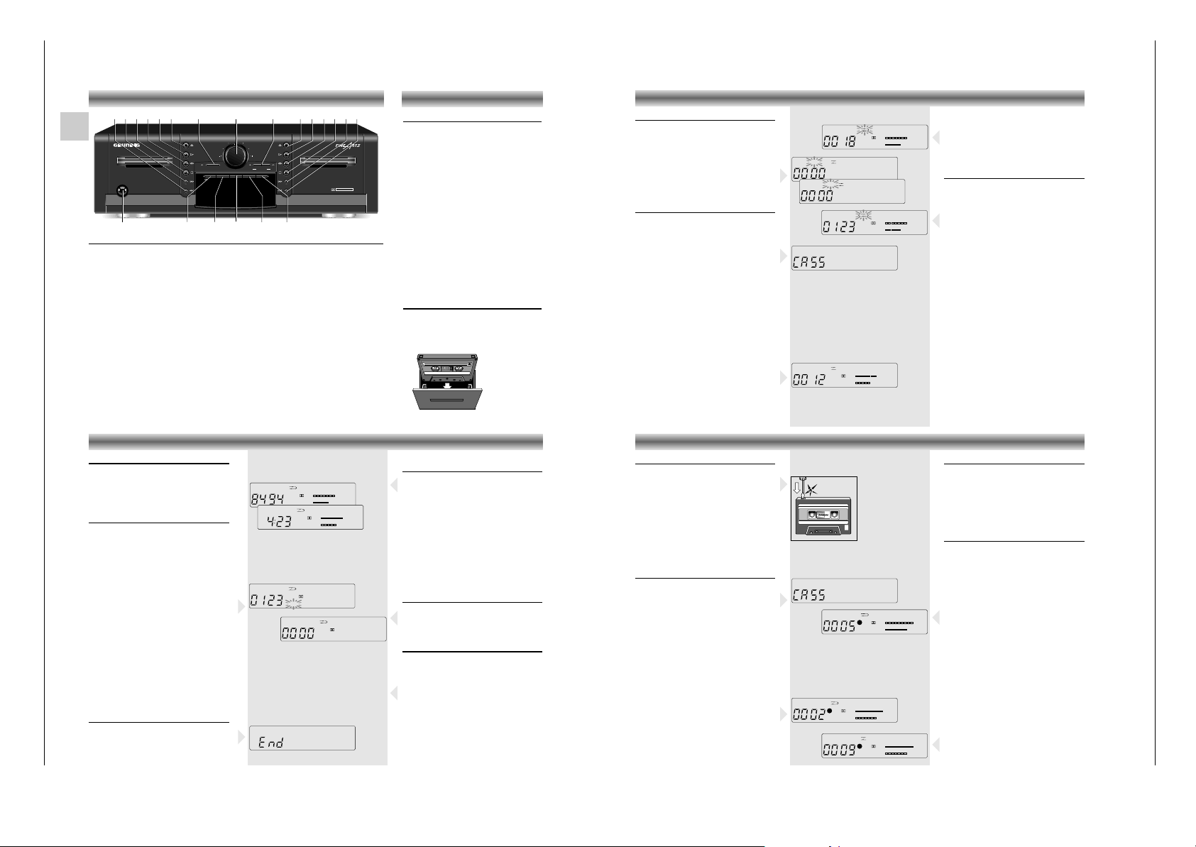
Bedienhinweise
Dieses Kapitel enthält Auszüge aus der Bedienungsanleitung. Weitergehende Informationen entnehmen Sie bitte
der gerätespezifischen Bedienungsanleitung, deren Sachnummer Sie in der entsprechenden Ersatzteilliste finden.
D
Vorderseite des Kassettendecks
POWER Dieser Schalter wird zum Ein- und Ausschalten des Geräts verwendet.
Laufwerk-Steuertasten Deck A und B:
QR
Gerät befindet sich in STOP: schneller Rück- oder Vorlauf.
Aus Wiedergabe gedrückt: MUSIC SEARCH rückwärts (Musik-Suchlauf zum
vorherigen
Titel) oder vorwärts (Musik-Suchlauf zum nächsten Titel).
9 Mit dieser Taste beenden Sie alle Funktionen.
A B Auswahl der wiederzugebenen Kassettenseite.
B Mit dieser Taste starten Sie die Wiedergabe
? Mit dieser Taste öffnen Sie das Kassettenfach.
RECORD/MUTE Mit dieser Taste starten Sie die Funktion Aufnahme.
RECORD LEVEL Hiermit stellen Sie den Aufnahmepegel ein.
DUBBING Mit dieser Taste starten Sie den Kassetten-Kopiervorgang:
NORMAL: mit normaler Geschwindigkeit, HIGH: mit doppelter Geschwindigkeit.
d B-C NR Diese Taste wählt das Rauschunterdrückungssystem.
0-SET Mit dieser Taste setzen Sie das Zählwerk auf Null zurück.
MEMO Mit dieser Taste können Sie Bandpositionen speichern. (nur deck B)
INFO Mit dieser Taste schalten Sie zwischen den Anzeigen COUNTER (Bandzählwerk) und
TIME (Echtzeit in Sekunden und Minuten) um.
REVERSE MODE Wahlschalter für Reverse-Betrieb:
å – die Wiedergabe oder Aufnahme stoppt am Ende jeder Kassettenseite.
∂ – Wiedergabe oder Aufnahme auf beiden Kassettenseiten; das Band
stoppt am Ende der zweiten Seite.
∫ – Folgewiedergabe von beiden Kassettenseiten.
ALLGEMEINES
Ein- und Ausschalten
•
Wollen Sie das Gerät ein- oder ausschalten,
drücken
Sie den Netzschalter POWER. Die
Betriebsanzeige,
eine gelbe Leuchtdiode in
der Mitte des Einschaltknopfes, informiert Sie
über den Schaltzustand:
gedrückt: EIN
ausgerastet: AUS.
• Wollen Sie das Gerät ausschalten, drücken
Sie den Netzschalter POWER nochmals.
• Haben Sie Ihr Gerät an die Wechselspannungs-
Ausgänge AC OUTLETS des
Verstärkers angeschlossen,
dient der
Netzschalter des Verstärkers als Zentralschalter. Lassen Sie den Schalter POWER des
Kassettendecks immer gedrückt.
– Nach dem Einschalten ist das Gerät immer im
STOP-Modus. Die Einstellung des d B-C NRSchalters und des REVERSE MODE Schalters
ist dieselbe wie vor dem Ausschalten. Die
letzte Stellung des Bandzählwerkes wurde
ebenfalls gespeichert.
Kassette einlegen
• Mit der Taste ? öffnen Sie das Kassettenfach.
• Legen Sie die Kassette mit der offenen Seite
nach unten in die Vertiefung des Faches.
• Schließen Sie das Kassettenfach von Hand.
HIFI DOUBLE CASSETTE DECK CCF23
POWER
RECORD/MUTE
RECORD LEVEL
DECK A
PLAYBACK/AUTOREVERSE
DECK B
RECORD/PLAYBACK/AUTOREVERSE
0-SET
MEMOB-C NR INFO
DUBBING
NORMAL HIGH
REVERSE
MODE
DOLBY B - C NR HX PRO
9ABB B??
Q
R
9AB
Q
R
RECORD/MUTE RECORD LEVEL DUBBING
INFO REVERSE MODE0-SETPOWER MEMO
d B-C NR
Auswahl der Kassettenseite
Wenn Sie eine Kassette mit Seite B nach hinten
gerichtet in das Fach einlegen, sollten Sie
entweder FWD für Wiedergabe/Aufnahme der
Seite A oder REV für Seite B wählen.
• Die Laufrichtung des Bandes wird mit den
Tasten ABausgewählt. Im Display
erscheint die Richtung als FWD oder REV.
• Nach Schließen des Kassettenfachs wählt das
Gerät immer automatisch FWD.
Wiedergabe
• Die Wiedergabe läßt sich nur starten, wenn
Sie eine Kassette eingelegt haben.
– Betätigen Sie eine der Tasten B, Q, R,
A B, RECORD/MUTE oder DUBBING, ohne
eine Kassette eingelegt zu haben, zeigt das
Display für 1,5 Sekunden
CASS
.
Wiedergabe einer Kassettenseite (deck A oder B)
• Das Kassettenfach des gewünschten Laufwerks
durch Drücken der entsprechenden ?-Taste öffnen.
• Eine bespielte Kassette mit der Öffnung nach
unten einlegen.
• Drücken Sie den
REVERSE MODE
-Wahlschalter
bis å im Display erscheint.
• Wählen Sie mit der Taste
d B-C NR
das
Rauschunterdrückungssystem, mit dem die
Kassette aufgenommen wurde.
• Wählen Sie mit der Taste ABdie Bandlaufrichtung.
• Drücken Sie die Taste
B (Laufwerk A oder B)
um die Wiedergabe zu starten.
–
Die Bargraph-Anzeige im Display informiert Sie
über die Pegelspitzen der aufgenommenen Musik.
– Am Bandende wird das Band gestoppt.
• Drücken Sie auf 9, wenn Sie das Band vor
dem Bandende stoppen möchten.
WIEDERGABE
Wiedergabe beider Kassettenseiten (Deck A oder B)
• Zur Wiedergabe beider Kassettenseiten
drücken Sie den REVERSE MODE-
Wahlschalter
bis im Display ∂ erscheint.
– Das Gerät gibt beide Kassettenseiten wieder;
die Wiedergabe stoppt automatisch am Ende
von Seite zwei.
Dauerwiedergabe
Dauerwiedergabe mit zwei Kassetten
•
Legen Sie in beide Kassettenfächer eine bespielte
Kassette ein und schließen Sie die Kassettenfächer.
• Drücken Sie den
REVERSE MODE
-Wahlschalter
bis ∫ im Display erscheint.
• Wählen Sie mit der Taste ABdie Bandlaufrichtung von Deck A.
– Deck A gibt beide Kassettenseiten wieder;
anschließend startet Laufwerk B und gibt
ebenfalls beide Kassettenseiten wieder.
– Deck A startet erneut; beide Decks
wiederholen beide Kassettenseiten, etc.
• Zum Beenden der Wiedergabe, drücken Sie
auf 9.
Aufmerkung: Wenn die Wiedergabe mit Deck B
starten soll, wählen Sie zuerst die Bandlaufrichtung
mit der Taste ABund drücken dann die Taste
B von Deck B.
Dauerwiedergabe mit eine Kassette
• Legen Sie nur eine bespielte Kassette ein und
schließen Sie das Kassettenfach.
• Drücken Sie den
REVERSE MODE
-Wahlschalter
bis ∫ im Display erscheint.
• Wählen Sie mit der Taste
ABdie Bandlauf-
richtung.
• Drücken Sie die Taste B (Laufwerk A oder B)
um die Wiedergabe zu starten.
–
Das gewählte Deck wiederholt beide Kassettenseiten, bis die Taste 9 am betreffenden
Laufwerk gedrückt wird.
B
+80-6-12-18 +4dB
L
R
B
FWDDECK A
B
+80-6-12-18 +4dB
L
R
B
FWDDECK A
➥
➥
+80-6-12-18 +4dB
L
R
+80-6-12-18 +4dB
L
R
REV
FWDDECK A
DECK A
B
+80-6-12-18 +4dB
L
R
B
FWDDECK A
Schneller Vor-/Rücklauf einer Kassette
Diese Funktionen sind nur aus STOP heraus möglich.
• Drücken Sie auf Q oder R .
– Der Schnellauf wird in der gewählten Richtung
gestartet und das Display zeigt Q oder R.
• Beenden: Taste 9 STOP drücken.
Funktion MUSIC SEARCH
Die Tasten Q und R ermöglichen die
direkte Anwahl von Titeln einer Kassette durch
Überspringen eines oder mehrerer Titel. Während
der Wiedergabe kann durch kurzes Drücken der
Tasten QRdirekt auf ein bestimmtes Stück
zugegriffen werden. Bis zu 15 Titel können in
beide Richtungen übersprungen werden.
• Drücken Sie einmal
R, spult das Gerät bis
an den Anfang des nächsten Titels.
Drücken Sie
einmal Q, spult das Gerät
bis an den
Anfang des aktuellen Titels zurück.
• Drücken Sie die Taste R zweimal, so wird
der zweite Titel in Vorwärtsrichtung gesucht,
drücken Sie die Taste dreimal, wird das dritte
Musikstück gesucht (max. 15 Titel).
–
Das Gerät schaltet auf Schnellauf zum gewählten
Titel und die Wiedergabe startet automatisch.
Voraussetzung ist, daß zwischen den einzelnen
Stücken Pausen von jeweils 4 Sekunden
aufgenommen wurden.
Hinweis: Bei Titeln mit extrem leisen
Musikpassage
n kann es vorkommen, daß diese
vom Musik-Suchlauf als Pausen erkannt werden.
Abschalten am Bandende
Aus allen Lauffunktionen schaltet das Laufwerk am
Bandende auf 'STOP'.
• Versuchen Sie am Bandende die Wiedergabe
oder den Bandschnellauf in die falsche
Richtung zu starten, zeigt das Display END.
WIEDERGABE WEITERE LEISTUNGSMERKMALE
B
+80-6-12-18 +4dB
L
R
MEMO
FWDDECK A
B
+80-6-12-18 +4dB
L
R
B
R
FWDDECK A
R
➥
➥
+80-6-12-18 +4dB
L
B
B
+80-6-12-18 +4dB
L
R
B
B
FWDDECK A
FWDDECK A
Umschalten von Bandzählwerk auf
Echtzeit
• Mit der Taste INFO schalten Sie zwischen
Bandzählwerk und Anzeige der Echtzeit
(Minuten und Sekunden) um.
Abstimmung der Echtzeitanzeige
Die Echtzeitmessung muß sich erst auf die Dicke
des verwendeten Bandmaterials in der Kassette
einstellen.
Starten Sie z. B. die Wiedergabe, blinkt der
Doppelpunkt zwischen der Minuten- und
Sekundenanzeige (-:--) für einige Zeit.
Während dieser Zeit werden die Banddicke und
andere Werte berechnet. Ist dieser Vorgang
abgeschlossen, läuft die Anzeige der Echtzeit
auch bei schnellem Vor- und Rücklauf mit.
Zurücksetzen des Zählwerkes
• Drücken Sie z. B. am Beginn einer Aufnahme
die Taste 0-SET, um den Zählerstand auf Null
zurückzusetzen.
Speichern von Bandpositionen
(nur Deck B)
• Durch drücken der Taste MEMO, können Sie
die momentane Bandposition speichern.
– Im Display erscheint das Zeichen MEMO.
• Betätigen Sie dann im STOP-Betrieb die Taste
Q (schneller Rücklauf), spult das Gerät
zurück und stoppt an der entsprechenden
Stelle.
• Drücken Sie die Taste MEMO erneut, beenden
Sie die Funktion.
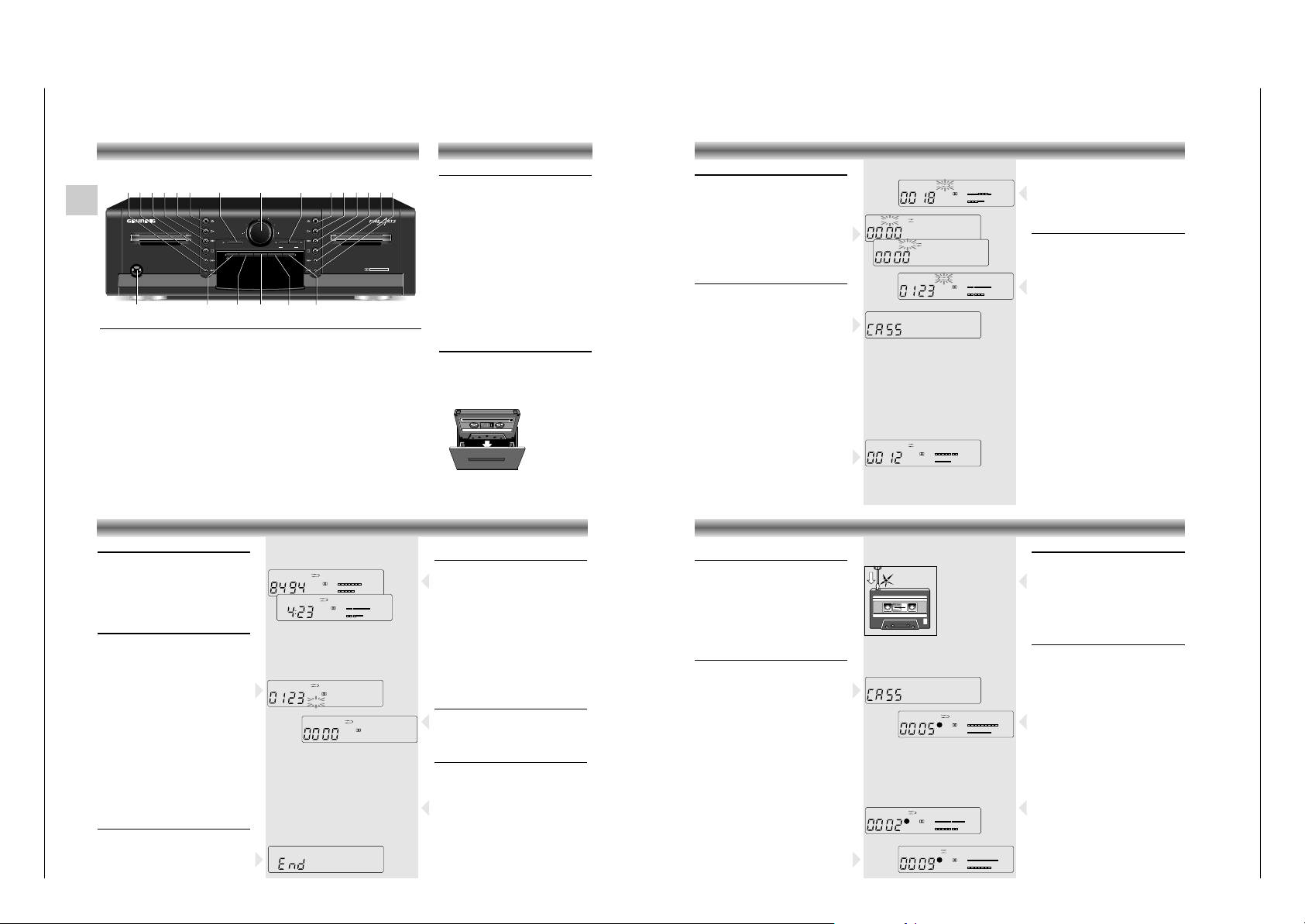
AUFNAHME (Deck B)
Kassette gegen Löschen schützen
Bei jeder Aufnahme wird die vorherige
Aufzeichnung überspielt.
Selbstbespielte Kassetten können Sie gegen versehentliches Löschen schützen, indem Sie die
entsprechende Sicherungsnase aus der Öffnung
im Kassettenrücken brechen, z.B. mit einem
Schraubenzieher.
Bespielt gekaufte Kassetten (Musik-Kassetten) sind
bereits gegen versehentliches Löschen gesichert.
Wollen Sie eine gesicherte Kassette neu
bespielen, überkleben Sie die entsprechende
Öffnung mit Klebeband.
Vorbereiten der Aufnahme
Copyright: Aufzeichnungen sind insoweit erlaubt,
als dadurch das Copyright oder andere Rechte
Dritter nicht verletzt werden.
Bei Kassetten mit Löschsicherung ist die Aufnahme
gesperrt, das Display zeigt für 1,5 Sekunden
CASS und sperrt die Aufnahme.
• Legen Sie eine Kassette die nicht gegen
Aufnahmen geschützt ist mit der offenen Seite
nach unten in Deck B ein und spulen Sie die
Kassette an die vorgesehene Bandstelle.
• Schalten Sie das Rauschminderungs-System mit
d B-C NR ein. Das Display informiert Sie über
die gewählte Einstellung.
• Wählen Sie am Verstärker die Signalquelle,
von der Sie aufnehmen möchten.
• Drücken Sie die Taste RECORD/MUTE:
– Das Gerät schaltet auf 'Aufnahme-Pause'.
– Die rote LED neben der Taste leuchtet.
– Die Anzeigen REC und ; leuchten im Display.
– Die Bargraphanzeige im Display zeigt den
Aufnahmepegel den Sie mit dem Regler
RECORD LEVEL einstellen können.
REC
B
+80-6-12-18 +4dB
L
R
B
MEMO
FWDDECK B
;
REC
B
+80-6-12-18 +4dB
L
R
FWDDECK B
REC
B
+80-6-12-18 +4dB
L
R
B
MEMO
FWDDECK B
1
Einstellen des Aufnahmepegels
Eine Aufnahme sollte richtig ausgesteuert sein.
Dies bedeutet, an den lautesten Passagen der
Aufnahme die Pegelanzeige (dB) im Display bis
'0' dB (=100% Aussteuerung) aufleuchten darf.
• Mit dem Einsteller RECORD LEVEL stellen Sie
den richtigen Aufnahmepegel ein.
Beginn der Aufnahme
Aufnahme auf beiden Kassettenseiten
• Wählen Sie die erste Kassettenseite, auf der
Sie aufnehmen möchten mit der Taste AB.
• Den Wahlschalter REVERSE MODE so oft
drücken bis im Display ∂ erscheint.
• Taste
B auf Deck B drücken um die Aufnahme
zu starten.
–
Die Anzeigen REC und B leuchten im Display auf.
– Die rote LED neben der Taste leuchtet.
•
Falls gewünscht drehen Sie den Einsteller LEVEL
zum Ausblenden der Musik langsam nach links
und zum Einblenden nach rechts in die Position
des jeweils gewünschten Aufnahmepegels.
– Das Laufwerk wechselt, nachdem die erste
Seite bespielt wurde, die Kassettenseite. Jetzt
wird die zweite Seite bespielt.
•
Vorzeitig beenden: Drücken Sie die Taste 9.
Aufnahme auf einer Kassettenseite
• Zur Aufnahme auf einer Kassettenseite gehen
Sie vor wie unter ‘Aufnahme auf beiden
Kassettenseiten’ beschrieben, jedoch drücken
Sie den REVERSE MODE-Wahlschalter bis å
im Display erscheint.
– Das Gerät stoppt den Aufnahmevorgang
automatisch, wenn das Bandende erreicht ist.
BEDIENELEMENTE
Page 5
CCF 23 Allgemeiner Teil / General Section
GRUNDIG Service 1 - 5
Operating Instructions
This chapter contains excerpts from the operating instructions. For further particulars please refer to the
appropriate user instructions the part number of which is indicated in the relevant spare parts list.
GB
Front of the cassette deck
POWER To switch the cassette deck on and off.
Cassette drive operating buttons for Deck A and B:
QR
When the unit is in STOP mode: fast winding forward or backward.
When pressed during playback: MUSIC SEARCH forward (music search to the begin
-
ning of next tracks) or backward (music search to the beginning of the previous tracks).
9 To stop all functions.
A B To select the playback direction (side) of the cassette.
B To start playback.
? Opens the cassette compartment.
RECORD/MUTE To start the recording function.
RECORD LEVEL For setting the recording level.
DUBBING For dubbing cassettes: NORMAL: at normal speed HIGH at high speed.
d B-C NR To select the noise reduction system.
0-SET For setting the tape counter to zero.
MEMO This button is used for storing a tape position (only deck B)
INFO This button is used for switching between the COUNTER (tape counter) and TIME (real
time in minutes and seconds) display.
REVERSE MODE Reverse mode selector:
å – The tape stops at the end of each side.
∂ – Playback (or recording) of both cassette sides; after which the tape stops
at the end of the second side.
∫ – Continuous playback of both cassette sides.
HIFI DOUBLE CASSETTE DECK CCF23
POWER
RECORD/MUTE
RECORD LEVEL
DECK A
PLAYBACK/AUTOREVERSE
DECK B
RECORD/PLAYBACK/AUTOREVERSE
0-SET
MEMOB-C NR INFO
DUBBING
NORMAL HIGH
REVERSE
MODE
DOLBY B - C NR HX PRO
9ABB B??
Q
R
9AB
Q
R
RECORD/MUTE RECORD LEVEL DUBBING
INFO REVERSE MODE0-SETPOWER MEMO
d B-C NR
Switching on and off
• When you want to switch your cassette deck
on, press the POWER button. The yellow light
in the middle of the button indicates that the
unit is on.
button depressed: POWER ON
button not depressed: POWER OFF
• When you want to switch the unit off, simply
press the POWER button again.
•
If the mains plug of your cassette deck is
connected
to one of the AC OUTLETS on the
amplifier, the
POWER button of the amplifier
serves as the central
switch for all units
connected to the AC OUTLETS.
– After switching on, your unit is always in the
STOP mode. The d B-C NR switch and the
REVERSE MODE selector remain in the setting
they were in when the unit was switched off.
The last tape counter position is also stored.
Inserting a cassette
• Press the ? button to open the cassette
compartment.
• Insert the cassette, with the open side down,
into the compartment.
• Close the cassette compartment by hand.
GENERAL
Selecting the tape side
If you place a cassette with side A facing you,
you should select the direction FWD for
playback/recording of side A and REV for
playback/recording of side B.
• The tape travel direction for both decks is
selected with the buttons AB.
The direction is indicated on the display as
FWD or REV.
• After closing the compartment the unit always
automatically selects the FWD direction.
Playback
• Playback can only be started if there is a
cassette in the cassette compartment.
–
If you press B, Q, R, A B, RECORD/-
MUTE or DUBBING, and the compartment is
empty,
CASS appears on the display for 1.5
seconds
.
Playback of one side (deck A or B)
• Open the cassette holder by pressing the
corresponding ? button.
• Insert a recorded cassette with the open side
facing down and close the cassette holder
• Press the REVERSE MODE selector until å
appears on the display.
•
With d B-C NR, select the noise reduction system
with which the cassette recording was made.
• Select the playback direction with AB.
• Now, press B on deck A or B.
– The bargraph in the display shows the sound
level of the recorded music.
– The deck plays one cassette side and stops
automatically at the end.
• If you want to stop the tape before it reaches
the end, simply press 9.
B
+80-6-12-18 +4dB
L
R
B
FWDDECK A
B
+80-6-12-18 +4dB
L
R
B
FWDDECK A
➥
➥
+80-6-12-18 +4dB
L
R
+80-6-12-18 +4dB
L
R
REV
FWDDECK A
DECK A
B
+80-6-12-18 +4dB
L
R
B
FWDDECK A
PLAYBACK
Playback of both sides (deck A or B)
• If you want to play both sides of the cassette,
press the REVERSE MODE selector until ∂
appears on the display.
– The deck plays both cassette sides and the
tape stops at the end of the second side.
Continuous playback
Continuous playback with two cassettes
• Insert a recorded cassette into both cassette
holders and close the cassette holders.
• Press the REVERSE MODE button until ∫
appears on the display.
• Select the playback direction of deck A with
the respective ABbutton.
• Press B on deck A.
– Deck A plays both cassette sides and then
deck B plays both cassette sides.
– Deck A starts again and both decks keep
playing both cassette sides continuously.
• Press 9 on the playing deck to stop continuous
playback.
Note: If you wish to start with deck B, first select
the playback direction of deck B with the respective ABbutton and then press B on deck B
Continuous playback with one cassette
• Insert only one recorded cassette into one of
the cassette holders and close the cassette
holder.
• Press the REVERSE MODE button until ∫
appears on the display.
• Select the playback direction with the
respective ABbutton.
• Press B (on deck A or B).
– The selected deck keeps playing both cassette
sides until you press
9 on the playing deck.
Fast winding
These functions are only possible when in the
STOP mode.
• Press
Q or R.
– The winding starts in the selected direction and
the indication Q or R lights up on the
display.
• To stop: press 9.
MUSIC SEARCH function
The Q and R keys also enable you to select
directly a desired track on a cassette by skipping
one or more tracks. This can be done by briefly
pressing the QRkeys during playback. Up
to 15 tracks can be skipped in each direction.
• If you press R once, the tape will wind to
the beginning of the next track. If you press
Q once, the tape will rewind to the
beginning of the current track.
• If you press R twice, the tape will advance
to the second track in forward direction,
pressing three times advances to the third
track, and so on to a max. of 15 tracks.
– The tape will wind to the beginning of the
selected track and playback will start
automatically.
The only requirement for this function is a 4second pause between each of the tracks.
Note: On some music tapes, the search function
may recognize extremely quiet passages as pauses.
Stop at the end of the tape
At the end of a tape, the cassette deck
automatically switches to "STOP."
• If you, being at the end of the tape, attempt to
start playback or fast winding in the wrong
direction, END is shown in the display.
PLAYBACK OTHER FEATURES
B
+80-6-12-18 +4dB
L
R
MEMO
FWDDECK A
B
+80-6-12-18 +4dB
L
R
B
R
FWDDECK A
R
➥
➥
+80-6-12-18 +4dB
L
B
B
+80-6-12-18 +4dB
L
R
B
B
FWDDECK A
FWDDECK A
Switching from the tape counter to
the real time display
• You can use the INFO button to switch
between the tape counter and the real time
display (minutes and seconds).
Calculation of the time
When you begin playback with real time
display, the colon between the minutes and
seconds field
(-:--) briefly blinks.
During this time the tape thick-ness and other
values are calculated. When this process is
concluded, the real time is displayed.
After this, the displayed time is also correct during
fast forward and fast reverse winding.
Resetting the tape counter
• Press the 0-SET button, for example at the
beginning of a recording, to reset the tape
counter to 0.
Storing tape positions (only deck B)
• You can store the current tape position by
pressing MEMO.
– The indication MEMO appears in the display.
• When you press Q (in stop mode), the
cassette deck rewinds and stops at the stored
position.
• Pressing MEMO again ends this function.
Protecting cassettes against
unintentional erasure
Every time you record onto a tape, its contents is
erased and replaced by the new recording.
In order to avoid unintentional erasure of a
recording, carefully remove its safety tabs with,
for example a screw driver.
Original recordings are already protected
against unintentional erasure.
If you wish to record on a 'protected' cassette, place
a small strip of tape over the corresponding holes.
Preparing to record (deck B)
Copyright: Making recordings from a prerecorded sound track is only permissible insofar as the
Copyright or the rights of third parties are not
infringed upon.
Recording on protected cassettes is not possible,
CASS appears in the display for 1.5 seconds,
and recording is prevented.
• Insert an unprotected cassette in the cassette
compartment of deck B and wind to the
desired tape position.
• Switch on the noise reduction system with
d B-C NR.
– The display indicates the selected setting.
• Select on the amplifier or receiver the source
from which you want to record
• Press RECORD/MUTE: the unit switches to
‘RECORD PAUSE’
– The red REC LED lights up.
–
The display shows the REC and ; indications.
– The Bargraph indication on the display shows
recording level which can be adjusted with the
RECORD LEVEL control.
RECORDING (deck B)
REC
B
+80-6-12-18 +4dB
L
R
B
MEMO
FWDDECK B
;
REC
B
+80-6-12-18 +4dB
L
R
FWDDECK B
REC
B
+80-6-12-18 +4dB
L
R
B
MEMO
FWDDECK B
1
Recording level adjustment
The recording level of your recording should be
properly adjusted.
This means that the loudest passages should not
exceed "0" in the recording level (dB) bargraph
display (= 100% modulation).
• You can set the correct recording level with the
LEVEL controller.
Starting recording
Recording on both sides of a cassette
•
Select the first side of the cassette in deck B onto
which you want to record with the button AB.
• Press the REVERSE MODE button until ∂
appears on the display.
• Press
B on deck B to start the recording.
–
The display shows the REC and B indications.
– The red REC LED lights up.
• If desired you can fade a recording out, by
slowly turning the REC LEVEL counter clockwise; to fade a recording in turn clockwise to
the desired recording level.
– The drive automatically changes the side of the
cassette after the first side has been recorded;
this is followed by recording on the second
side.
• Press
9 to stop recording at an earlier point.
Recording on one side of a cassette
• If you only want to record on one side of the
cassette, proceed as described above but
press the REVERSE MODE button until å
appears on the display.
– The unit automatically stops recording when
the end of the tape is reached.
OPERATING ELEMENTS
Page 6
Allgemeiner Teil / General Section CCF 23
Ausbauhinweise
Allgemeines zum mechanischen Teil.
Die Zahlen im Text und bei den Abbildungen sind mit den Positionsnummern der Zeichnungen in der Ersatzteilliste identisch.
Vor Beginn von Servicearbeiten ist das Gerät in die Funktion "STOP"
zu bringen, der Kopfschlitten ist dann zurückgefahren.
Mechanische Beschädigungen der Bandlaufflächen und Führungen
können dadurch vermieden werden.
Um bei mechanischen Arbeiten elektrische Bauteile nicht zu zerstören, ist nach zurückgefahrenem Kopfschlitten der Netzstecker aus der
Steckdose zu ziehen.
Alle Schrauben, die in Kunststoff eingedreht werden, sollten zuerst
soweit gegen den Uhrzeigersinn gedreht werden, bis Sie merken, die
Schraube hat den Gewindeanfang gefunden. Erst dann ist die Schraube festzudrehen. Dadurch wird vermieden, daß ein neues Gewinde
in den Kunststoff geschnitten wird und der Halt der Schraube verlorengeht.
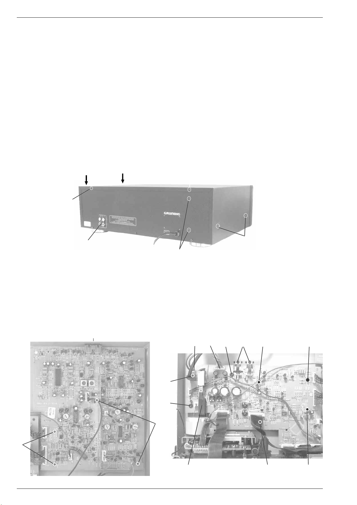
1. Öffnen des Gehäuses
- 6 Schrauben A herausdrehen (Fig. 1).
- Gehäuseoberteil hinten anheben und abnehmen.
A
A
A
Disassembly Instructions
General Notes on the Mechanical Section.
The numbers in the text and in the diagrams are the same as the
position numbers of the exploded views included in the spare parts list.
Before starting repair works set the tape deck to "STOP" position so
that the head carrier is in service position in order to avoid mechanical
damages to the surfaces contacting the tape and the guides.
With the head carrier in service position disconnect the mains plug to
ensure that the electrical components are not damaged during the
mechanical repair works.
All the screws which are screwed into plastic parts should be turned
counter clockwise first until you notice that the screw has found the first
thread. Then tighten the screw. This preventive measure ensures that
no new threads are cut into the plastic material thus deteriorating the
good fit of the screw.
1. Opening the Cabinet
- Undo 6 screws A (Fig. 1).
- Raise the cabinet top on the rear side and remove.
A
C
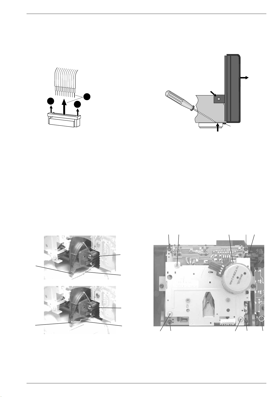
2. Netztrafo ausbauen
- Gehäuseoberteil abnehmen (siehe Pkt. 1).
- Steckverbindungen P 512 und P 513 abziehen (Fig. 3).
- 2 Schrauben B herausdrehen (Fig. 1).
- Trafo herausnehmen.
3. Audio-Platte ausbauen
- Gehäuseoberteil abnehmen (siehe Pkt. 1).
- 1 Schraube C herausdrehen (Fig. 1, 2).
- 4 Plattenhalter D (Fig. 2) ausrasten und Leiterplatte herausnehmen.
- Bei Bedarf Steckverbindungen abziehen.
C
A
B
Fig. 1
2. Removing the Transformer
- Remove the top of the cabinet (see para 1).
- Unplug the connectors P 512 and P 513 (Fig. 3).
- Undo 2 screws B (Fig. 1).
- Take out the transformer.
3. Removing the Audio Circuit Board
- Remove the top of the cabinet (see para 1).
- Undo 1 screw C (Fig. 1, 2).
- Unhook the 4 board holders D (Fig. 2) and remove the circuit board.
- Disconnect the plug-in connections if necessary.
P513 P512
EF
G
G
E
G
D
D
H
Fig. 2 Fig. 3
1 - 6 GRUNDIG Service
G
G
Page 7
CCF 23 Allgemeiner Teil / General Section
4.Logik-Platte ausbauen
- Gehäuseoberteil abnehmen (siehe Pkt. 1).
- 2 Schrauben E und 2 Schrauben F (Fig. 3) herausdrehen.
- 5 Plattenhalter G (Fig. 3) ausrasten.
- Netzschalter in Stellung "Aus" bringen und danach den Netzschalterstößel H (Fig. 3) abziehen.
- Steckverbindungen lösen und Leiterplatte herausnehmen.
2
1
5. Frontblende (mit Leiterplatten) ausbauen
- Gehäuseoberteil abnehmen (siehe Pkt. 1).
- 2 Cassettendeckel-Drehfedern I über die Zapfen J (Fig. 6) einhängen.
- Schraube 1 (Fig. 5) am Gehäuseboden herausdrehen.
- Laschen 2 links und rechts der Frontblende sowie 3 Haltezapfen 3
am Gehäuseboden ausrasten (Fig. 5).
- Netzschalter in Stellung "Aus" bringen und danach den Netzschalterstößel H abziehen (Fig. 3).
- Frontblende mit den Laufwerken vorsichtig nach vorne 4 abziehen
(Fig. 5).
- Bei Bedarf Steckverbindungen lösen.
6. Laufwerke ausbauen (A oder B)
- Gehäusefront abnehmen (siehe Pkt. 5).
- Drehfeder K aushängen (Fig. 7).
- 4 Schrauben L herausdrehen (Fig. 7).
- Laufwerk nach hinten herausnehmen.
1
Fig. 4
Steckverbindungen
Connectors
P 502 - P 506
4. Removing the Logic Board
- Remove the top of the cabinet (see para 1).
- Undo 2 screws E and 2 screws F (Fig. 3).
- Unhook the 5 board holders G (Fig. 3).
- Set the power switch to "Off", then disengage the push-rod H of the
power switch (Fig. 3).
- Disconnect the plug-in connections and remove the circuit board.
4
2
1
3
Fig. 5
5. Removing the Front Panel (with PCBs)
- Remove the top of the cabinet (see para 1).
- Attach the cassette lid torsion springs I to the lugs J (Fig. 6).
- Undo the screw 1 (Fig. 5) on the bottom of the cabinet.
- Disengage the lugs 2 on the left and right of the front panel and 3
prongs 3 on the bottom of the cabinet (Fig. 5).
- Set the power switch to "Off", then disengage the push-rod H of
the power switch (Fig. 3).
- Pull the front panel with the drive mechanisms carefully towards
the front 4 (Fig. 5).
- If necessary, disconnect the connectors.
6. Removing the Drive Mechanisms (A or B)
- Remove the front panel (see para 5).
- Unhook the torsion spring K (Fig. 7).
- Undo 4 screws L (Fig. 7).
- Take the drive mechanism out towards the rear.
LNNL
K
M
J
I
M
J
Fig. 6
7. Cassettenfach-Deckelbremse ausbauen (Laufwerk A oder B)
- Gehäuseoberteil abnehmen (siehe Pkt. 1).
- Schraube M herausschrauben (Fig. 6 und 7).
- Bremse nach hinten herausnehmen.
Achten Sie auf die Cassettendeckel-Drehfeder I (Fig. 6).
GRUNDIG Service 1 - 7
I
N
Fig. 7
7. Removing the Brake of the Cassette Compartment Lid
(Drive mechanism A or B)
- Remove the top of the cabinet (see para 1).
- Undo the screw M (Figs. 6 and 7).
- Take the brake out towards the rear.
Take care of the cassette lid torsion springs I (Fig. 6).
MLNL
Page 8
Allgemeiner Teil / General Section CCF 23
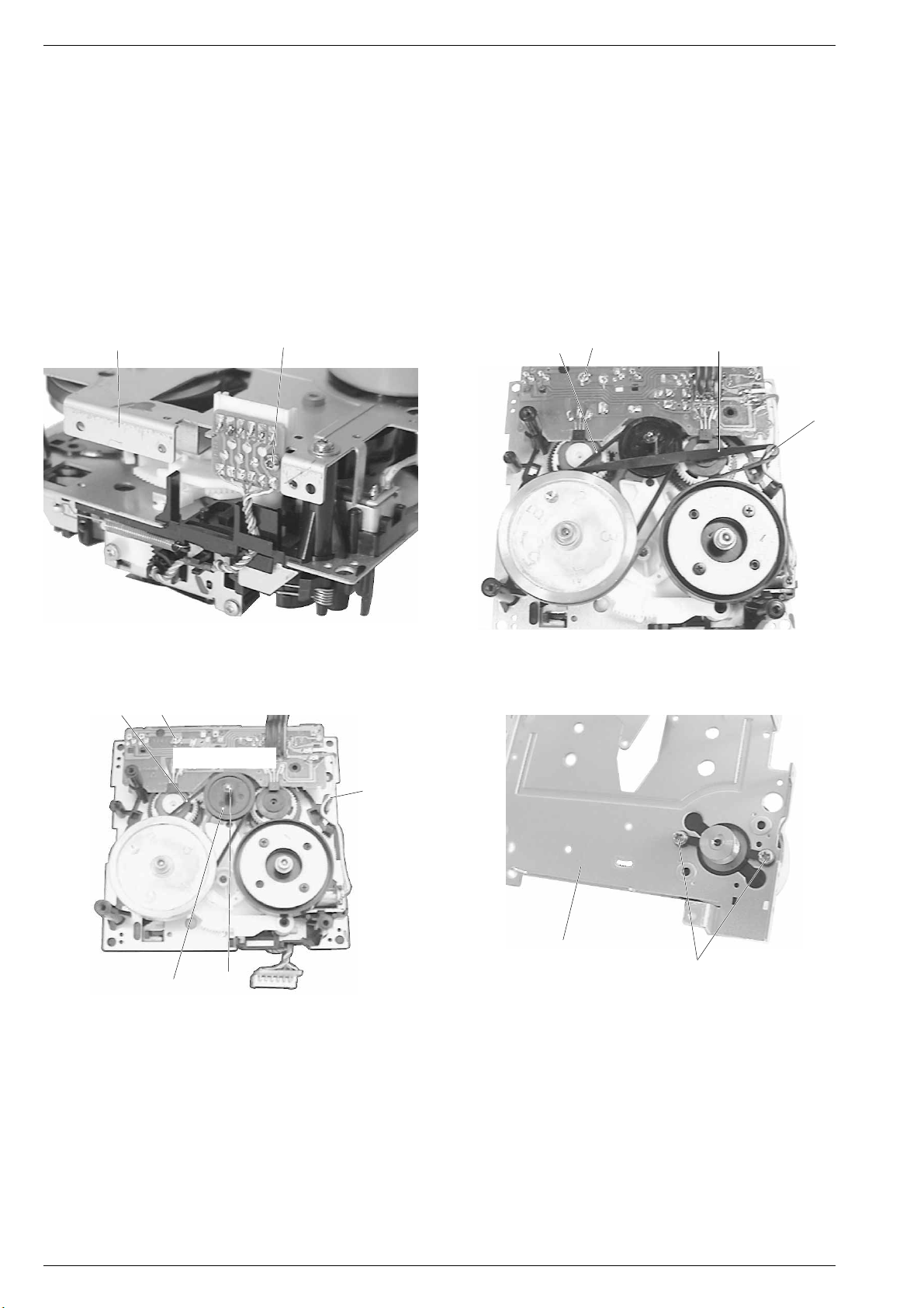
8. Laufwerkmotor ausbauen
- Laufwerk ausbauen (siehe Pkt. 6).
- 4 Schrauben N herausdrehen (Fig. 7).
- Schraube P herausdrehen und Buchsenplatte abnehmen (Fig. 8).
- Nehmen Sie den Antriebsriemen 45 von der Motorriemenscheibe
und legen Sie ihn über den hochstehenden Bolzen Q (Fig. 9).
- Laufwerkabdeckung 41 mit Motor abnehmen.
- 2 Schrauben R herausschrauben, den Motor aus der Führung
herausnehmen und ablöten (Fig. 11).
9. Antriebsriemenwechsel
- Die Vorarbeiten zum Wechseln des Antriebsriemens 45 und des
Riemens 24 sind wie beim Laufwerkmotorwechsel (siehe Pkt. 8).
- Riemen wechseln.
Achtung!
frei von Öl und Fett sein.
Riemen, Andruckrollen und Bandkontaktstellen müssen
41 24
P
8. Removing the Motor of the Drive Mechanism
- Dismantle the drive mechanism (see para 6).
- Undo 4 screws N (Fig. 7).
- Undo the screw P and take out the socket board (Fig. 8).
- Take off the drive belt 45 from the motor pulley and put it around the
upright bolt Q (Fig. 9).
- Remove the cover 41 from the drive mechanism with the motor.
- Undo 2 screws R, take the motor out from the guide and unsolder
it (Fig. 11).
9. Changing the Drive Belt
- The preparations for changing the drive belt 45 and the belt 24 are
the same as for replacing the motor of the drive mechanism (see
para 8).
- Replace the belt(s).
Warning!
the tape must be free of oil and grease.
Belts, pressure rollers and parts coming into contact with
S
45
Q
Fig. 8 Fig. 9
S
24
Laufwerk-Platte
Drive mechanism Board
Q
23
10. Laufwerk-Platte ausbauen
- Laufwerkabdeckung mit Motor ausbauen (siehe Pkt. 8).
- Schraube S herausschrauben (Fig. 10).
- Bei Bedarf die Leitungen zum Bremslüftmagnet und Motor ablöten.
- Leiterplatte herausnehmen.
102
Fig. 10 Fig. 11
41
R
10. Removing the Drive Mechanism Circuit Board
- Remove the cover of the drive mechanism with motor (see para 8).
- Undo screw S (Fig. 10).
- Unsolder the leads to the brake lifting magnet and the motor.
- Take out the circuit board.
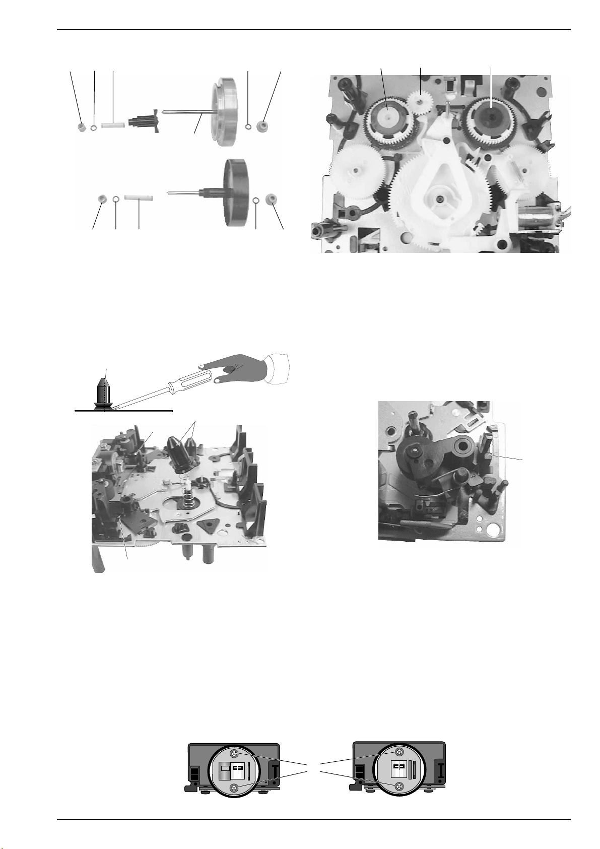
11. Schwungrad wechseln
- Laufwerkabdeckung mit Motor ausbauen (siehe Pkt. 8).
- Riemen 45 bzw. 24 abnehmen.
- Ziehen Sie das Schwungrad nach hinten heraus.
Achten Sie beim Aus- und Einbau des Schwungrades auf die beiden
Lager 3, die beiden Scheiben 4 und die Feder 5 (Fig. 12).
Nach dem Einbau des Schwungrades muß die Capstanwelle mit
Spiritus oder Reinigungsbenzin gereinigt werden.
1 - 8 GRUNDIG Service
11. Replacing the Flywheel
- Remove the cover of the drive mechanism with motor (see para 8).
- Remove the belt(s) 45 and 24 respectively.
- Withdraw the flywheel towards the rear.
When removing and refitting the flywheel take care of the two
bearings 3, the two washers 4 and the spring 5 (Fig. 12).
After having fitted the new flywheel the capstan must be cleaned with
spirit or cleaning benzine.
Page 9
CCF 23 Allgemeiner Teil / General Section
44
3
32 103
12. Kupplungswechsel (17, 29)
- Laufwerkplatte ausbauen (siehe Pkt. 10).
- Schwungräder ausbauen (siehe Pkt. 11).
- Scheibe 102 und Riemenscheibe 23 abziehen (Fig. 10).
- Wickeldorn 9 aushebeln und abziehen (Fig. 14).
- Bei Bedarf das Zahnrad 21 abziehen (Fig. 13).
- Nehmen Sie die Kupplung nach hinten heraus.
5
33
25 103 72 103
445
3
26
Fig. 12
3
3410373 33.1
27
21
1729
3
Fig. 13
12. Replacing the Clutch (17, 29)
- Remove the drive mechanism circuit board (see para 10).
- Remove the flywheel(s) (see para 11).
- Pull off the washer 102 and the pulley 23 (Fig. 10).
- Lift off and remove the spindle 9 (Fig. 14).
- If necessary pull off the gearwheel 21 (Fig. 13).
- Remove the clutch towards the rear.
9
9
65
69
Fig. 14 Fig. 15
13. Andruckrolle wechseln
- Laufwerk ausbauen (siehe Pkt. 6).
- Untere Drehfeder 65 bzw. 69 aushängen (Fig. 14).
- Rastnase T ausrasten und die Andruckrolle abziehen (Fig. 15).
- Beim Einbau sind die Federn wieder einzuhängen.
14. Tonkopf wechseln
- Laufwerk ausbauen (siehe Pkt. 6).
- Kopfleitungen aushängen.
- 2 Schrauben U herausdrehen und den Tonkopf herausnehmen
(Fig. 16).
- Kopfleitungen ablöten.
- Beim Einbau sind die Kopfleitungen wieder einzuhängen.
T
13. Replacing the Pressure Roller
- Dismantle the drive mechanism (see para 6).
- Unhook the lower torsion spring 65 or 69 (Fig. 14).
- Disengage the locking lug T and pull out the pressure roller
(Fig. 15).
- Refit the springs when mounting the new pressure roller.
14. Replacing the Sound Head
- Remove the drive mechanism (see para 6).
- Detach the head leads.
- Undo 2 screws U and remove the sound head (Fig. 16).
- Unsolder the head leads.
- Attach the head leads when re-assembling.
U
Deck B Deck A
GRUNDIG Service 1 - 9
Fig. 16
Page 10

Allgemeiner Teil / General Section CCF 23
15. Cassettentür-Verriegelung ausbauen (A oder B)
- Gehäuseoberteil abnehmen (siehe Pkt. 1).
- Cassettenfachdeckel öffnen.
- Drehfeder K (Fig. 17) aushängen.
- Verriegelungshebel V nach oben in Pfeilrichtung aus der Halterung
drücken (Fig. 17).
K
Fig. 17
V
15. Disassembling the Locking of the Cassette Lid (A or B)
- Remove the top of the cabinet (see para 1).
- Open the cassette compartment lid.
- Unhook the torsion spring K (Fig. 17).
- Push the locking lever V out of the holder in the direction of the
arrow (Fig. 17).
W
Fig. 18
W
16. Cassettenfachdeckel abnehmen
- Cassettenfach öffnen.
- Rastnasen W des Cassettenfachdeckels unten ausrasten und
Deckel nach oben abnehmen (Fig. 18).
17. Cassettentüren ausbauen (A oder B)
- Laufwerk ausbauen (siehe Pkt. 6).
- Cassettenfach-Deckelbremse ausbauen (siehe Pkt. 7).
- Cassettenfachdeckel abnehmen (siehe Pkt. 16).
- 2 Schrauben X (Fig. 19) herausdrehen und Abdeckblech Y abnehmen.
- Cassettentürführungen Z (Fig. 19) aushängen und die Tür vorsichtig nach hinten herausnehmen.
- Achten Sie dabei auf die Drehfeder I.
Y
XX
16. Removing the Cassette Compartment Cover
- Open the cassette compartment lid.
- Disengage the locking lugs W on the underside and pull the cassette
compartment cover upwards to remove it (Fig. 18).
17. Removing the Cassette Compartment Lids (A or B)
- Remove the drive mechanism (see para 6).
- Remove the brake of the cassette compartment lid (see para 7).
- Remove the cassette compartment cover (see para 16).
- Undo 2 screws X (Fig. 19) and remove the metal plate Y.
- Detach the guides of the cassette compartment lid Z (Fig. 19) and
take it out carefully towards the rear.
- Take care of the torsion spring I.
I
ZZ
Fig. 19
1 - 10 GRUNDIG Service
Page 11

CCF 23 Einstellvorschriften / Adjustment Procedures
j
Einstellvorschriften
Meßgeräte/Meßmittel:
Frequenzzähler, DC-Voltmeter, NF-Voltmeter, NF-Generator, Klirranalysator, Tonhöhenschwankungsmesser,
Cr-Testcassette 448 A (Sach-Nr. 35079-023.00), Drehmomentcassette 456 (Sach-Nr. 35079-014.00).
Abgleich-Lageplan siehe Seite 2 - 3. Bandlaufeinstellung siehe Seite 2 - 6. Die Symbole weisen auf Meßpunkte im Schaltbild hin.
Abgleich Vorbereitung Abgleichvorgang
1. Bandgeschwindigkeit
Deck A/B
2. Aufwickelmoment bei Start
Deck A/B
3. Gleichlauf
Deck A/B
4. KopfspaltSenkrechtstellung
(Azimut)
Deck A/B
Frequenzzähler an LINE OUT.
Testcassette 448 A einlegen (Deck A bzw. Deck B),
3150 Hz abspielen.
1. High Speed-Einstellung:
- Wiedergabe Deck A bzw. Deck B.
- Basis + Emitter am Trans. T523 kurzschließen.
2. Normal Speed-Einstellung:
- Wiedergabe Deck A bzw. Deck B.
Drehmomentcassette 456 einlegen (Deck A bzw. B).
Funktion: Start
Tonhöhenschwankungsmesser an LINE OUT.
Testcassette 448 A einlegen (Deck A bzw. Deck B),
3150Hz abspielen.
NF-Voltmeter an LINE OUT L (linker Kanal) bzw. an LINE
OUT R (rechter Kanal) anschließen.
Testcassette 448 A einlegen (Deck A bzw. Deck B),
10kHz abspielen.
W-Kopf Deck A AW-Kopf Deck B
21 12
1. High Speed-Einstellung: Mit dem Einstellregler R566
(Deck A) bzw. mit R561 (Deck B) 6300Hz ±0,1% einstellen.
2. Normal Speed-Einstellung: Mit dem Einstellregler R564
(Deck A) bzw. mit R558 (Deck B) 3150Hz ±0,1% einstellen.
Bei der Gerätefunktion START soll das Drehmoment
25 bis 70 x 10-4Nm ≈ 40g-cm betragen.
Gleichlaufabweichung < 0,13% (IEC wtd).
Wiedergabemeßzeit ≥ 30 Sekunden.
Deck A bzw. B
Bandlaufrichtung "Normal"
Mit der Kopfeinstellschraube 1 den linken oder rechten
Kanal auf Pegelmaximum einstellen.
Danach linken und rechten Kanal (LINE OUT) parallel
schalten. Durch kleinstmögliches Nachstellen der Kopfeinstellschraube 1 den Ausgangspegel auf Maximum einstellen.
Testcassette drehen.
Bandlaufrichtung "Reverse"
Einstellung mit der Kopfeinstellschraube 2 wie bei Bandlaufrichtung "Normal".
5. Wiedergabepegel
Bezugsbandabtastung
(Dolby-Pegel)
Deck A/B
6. Löschfrequenz
Deck B
7. Löschstrom
Deck B
8. HX-PRO
Deck B
9. Aufnahmesperrkreise
(Vormagnetisierungsfilter)
NF-Voltmeter an Meßpunkt D1 (linker Kanal) bzw. D2
(rechter Kanal).
Testcassette 448 A einlegen (Deck B bzw. Deck A).
315Hz (250nWb/m) abspielen.
Dolby aus.
Deck B zuerst einstellen.
Frequenzzähler an Meßpunkt L1 (R253).
Bespielbare Cassette der Bandsorte Cr (IEC II) einlegen.
Gerätefunktion: Aufnahme-Start
NF-Voltmeter an Meßpunkt L1 (parallel zu R253).
Bespielbare Cassette der Bandsorte Cr (IEC II) einlegen.
Gerätefunktion: Aufnahme-Start
Gleichspannungsvoltmeter an Pin13 IC105 (rechter
Kanal) bzw. an Pin6 IC105 (linker Kanal) anschließen.
Bespielbare Cassette der Bandsorte Cr (IEC II) einlegen.
Gerätefunktion: Aufnahme-Start, Dolby aus.
NF-Voltmeter an Meßpunkt D1 (linker Kanal) bzw. an
den Meßpunkt D2 (rechter Kanal).
Leercassette in Deck A einlegen.
Bespielbare Cassette der Bandsorte Cr (IEC II) in Deck B
einlegen.
Gerätefunktion: High Dubbing
NF-Voltmeter an Meßpunkt D3 (linker Kanal) bzw. an
den Meßpunkt D4 (rechter Kanal).
Gerätefunktion: High Dubbing
Bei Deck B mit den Einstellreglern R156 (links) bzw.
R157 (rechts) und bei Deck A mit den Einstellreglern
R154 (links) bzw. R155 (rechts) einen Wiedergabepegel
von 490mV ± 0,5dB einstellen.
(LINE OUT ≈ 950mV)
Bei Verwendung einer Testcassette mit 200nWb/m ist
der Wiedergabepegel auf 388mV ± 0,5dB einzustellen.
(LINE OUT ≈ 750mV)
Die Oszillatorfrequenz soll 85kHz ± 10kHz betragen.
Einstellen mit L103.
Löschstrom: 150mA ± 10%
gemessen an R253 = 150mV ± 10%.
Mit L104 am Pin13 IC105 (rechter Kanal) und mit L105 am
Pin6 IC105 (linker Kanal) Gleichspannungsminimum
einstellen.
Mit F200 am Meßpunkt D1 (linker Kanal) und mit F210
am Meßpunkt D2 (rechter Kanal) HF-Minimum einstellen.
Mit F106 am Meßpunkt D3 (linker Kanal) und mit F105 am
Meßpunkt D4 (rechter Kanal) HF-Minimum einstellen.
GRUNDIG Service 2 - 1
Page 12

Einstellvorschriften / Adjustment Procedures CCF 23
Abgleich Vorbereitung Abgleichvorgang
10. MPX-Filter
(19kHz Stereopilotton)
Deck B
11.Frequenzgangeinstellung bei
Wiedergabe
Deck A/B
12.NF-Kopfstromeinstellung bei
Eigenaufnahme
Deck B
NF-Generator an LINE IN-Buchsen.
f1= 315Hz, f2= 19kHz, Ue = 115mV ± 1,5dB.
NF-Voltmeter an Meßpunkt D1 (linker Kanal) bzw. an
Meßpunkt D2 (rechter Kanal).
Bespielbare Cassette der Bandsorte
Cr (IEC II) in Deck B einlegen.
10 k
10 k
≈
LINE IN
Gerätefunktion: Aufn.-Pause
Dolby aus
Aufnahme-Pegelregler "Maximum"
NF-Voltmeter an Meßpunkt D1 (linker Kanal) bzw.
Meßpunkt D2 (rechter Kanal).
Testcassette 448 A einlegen.
Frequenzbandteil 315Hz / 12,5kHz abspielen.
Dolby aus
NF-Voltmeter an Meßpunkt D1 (linker Kanal) bzw. an
Meßpunkt D2 (rechter Kanal).
Testcassette 448 A Seite B (Leerbandteil) Cr IEC II oder
vergleichbares Band einlegen.
NF-Generator an LINE IN-Buchsen.
Ue = 500mV, f = 400Hz.
Gerätefunktion: Aufnahme-Pause
10 k
10 k
≈
LINE IN
Dolby aus
–
Aufnahme-Start
–
Wdg.-Start
Eingangspegel (LINE IN) bei Aufnahme-Pause so einstellen, daß an den Meßpunkten D1 und D2 bei 315Hz
eine Ua von 388mV (= 0dB) zu messen ist.
Bei 19kHz = U
Mit F103 (linker Kanal) bzw. F 104 (rechter Kanal) einstel-
≤12mV (≤ –30dB).
a
len.
Deck B:
Beträgt die Pegeldifferenz an D1 bzw. D2 zwischen
Ua f1 (315Hz) und Ua f2 (12,5kHz) mehr als ± 1,5dB, so
sind die Brücken B1 (C103), B2 (C107) linker Kanal,
bzw. die Brücken B3 (C104), B4 (C108) rechter Kanal,
zu unterbrechen.
Deck A:
Beträgt die Pegeldifferenz an D1 bzw. D2 zwischen
Ua f1 (315Hz) und Ua f2 (12,5kHz) mehr als ± 1,5dB, so
sind die Brücken B5 (C109), B6 (C114) linker Kanal,
bzw. die Brücken B7 (C111), B8 (C115) rechter Kanal,
zu unterbrechen.
Uaf2 (12,5kHz)
Uaf1 (315Hz)
= +1 ± 0,5dB
Mit dem Pegelregler (RECORD LEVEL) bei Aufnahme an
den Meßpunkten D1 und D2 120mV einstellen.
Bei Wiedergabe der gemachten Aufnahme muß an den
Meßpunkten D1 und D2 ein Pegel von 120mV ±0,5dB
zu messen sein.
Wird dieser Wert nicht erreicht, so sind die Kopfstromregler R232 (linker Kanal) bzw. R233 (rechter Kanal) bei
Aufnahme nachzustellen.
Bei Aufnahmen mit Fe IEC I-Cassette müssen
120mV ±1dB zu messen sein.
13.Frequenzgang-
einstellung bei
Eigenaufnahme
Deck B
14.Vormagnetisierungsspannung
Deck B
15.Klirrfaktor
Deck B
NF-Voltmeter an Meßpunkt D1 (linker Kanal) bzw. an
Meßpunkt D2 (rechter Kanal).
Testcassette 448 A Seite B (Leerbandteil) Cr IEC II oder
vergleichbares Band einlegen.
NF-Generator an LINE IN-Buchsen.
Ue = 500mV, f1 = 400Hz, f2 = 12,5kHz.
Gerätefunktion: Aufnahme-Pause
Dolby aus
–
Aufnahme Start
–
Wdg.-Start
NF-Voltmeter über einem kapazitiven Spannungsteiler
1:1000 an Meßpunkt TP 5 (linker Kanal, Kopfstecker
P102/1) bzw. an Meßpunkt TP 6 (rechter Kanal, Kopfstecker P102/6).
Bespielbare Cassette der Bandsorte Fe bzw. Cr einlegen.
Gerätefunktion: Aufnahme-Start
NF-Voltmeter an Meßpunkt D1 (linker Kanal) bzw. an
Meßpunkt D2 (rechter Kanal).
Bespielbare Cassette der Bandsorte Fe bzw. Cr einlegen.
NF-Generator an die LINE IN-Buchsen.
Ue = 500mV, f = 333Hz.
Gerätefunktion: Aufnahme-Pause
10 k
10 k
≈
LINE IN
Dolby aus
–
Aufnahme Start
Mit dem Pegelregler (RECORD LEVEL) bei Aufnahme an
den Meßpunkten D1 und D2 22mV einstellen.
Bei Wiedergabe darf an den Meßpunkten D1 und D2
die Pegeldifferenz nicht größer als 0,5dB sein.
Ist Uaf2zu Uaf1 größer als 0,5dB, so ist eine Vormagnetisierungskorrektur vorzunehmen.
Einstellen mit R296 (li. Kanal) bzw. R295 (re. Kanal).
Uaf2 (12,5kHz)
Uaf1 (400Hz)
= 0dB ± 0,5dB
Die Vormagnetisierungsspannung ist abhängig von der
Bandsorte und der Frequenzgangeinstellung.
Einstellbereich:
Fe = 10 - 15V
CrO2= 18 - 25V
Mit dem Pegelregler (RECORD LEVEL) bei Aufnahme an
den Meßpunkten D1 und D2 388mV einstellen.
Klirranalysator an LINE OUT L bzw. LINE OUT R (mit
47kΩ abgeschlossen).
Gerätefunktion: Wiedergabe
Dolby aus
Klirrfaktor bei Wiedergabe der gemachten Aufnahme:
Fe IEC I K3 ≤ 1,5%
CrO2IEC II K3 ≤ 2,0%
2 - 2 GRUNDIG Service
Page 13

CCF 23 Einstellvorschriften / Adjustment Procedures
Abgleichlageplan
Alignment Scheme
AUDIO-PLATTE
AUDIO BOARD
D1
D2
D3
GND
MPX FILTER
F 104 F 103
LR
KOPFSTROM
HEAD CURRENT
P104P105
R 232
R
L
R 253
R 101
LR
F 106 F 105
AUFN. SPERRKREIS
BIAS FILTER
P 102
6
OSC.
FREQUENZ
FREQUENCY
L 103
VORMAGN.
LR
BIAS
1
6
HX-PRO
C108
R 295
AUFN. SPERRKREIS
13
IC 105
L 104L 105
R 296
LR
C104
WIEDERGABEPEGEL
PLAYBACK LEVEL
AABB
LR
LR
L
F 200
AUFN. SPERRKREIS
BIAS FILTER
C111
C115
B8
B6
B7
B5
R 157R 156
R 155R 154
F 210
1
C103
C114
C109
C107
L1 6TP 5TP
R 233
R
D4
R 102
BIAS FILTER
B4
B3
B1
B2
LOGIK-PLATTE
LOGIC BOARD
R 543
B
C
E
R 547
kurzschließen
short-circuit
(HIGH SPEED)
P507
T 523
DECK A
R 566R 564
NORMAL HIGH
BANDGESCHWINDIGKEIT
P506
TAPE SPEED
DECK B
R 558
R 561
NORMAL
P508
HIGH
P505
GRUNDIG Service 2 - 3
Page 14

Einstellvorschriften / Adjustment Procedures CCF 23
k
Adjustment Procedures
Measuring instruments/equipment:
Frequency counter, AF voltmeter, DC voltmeter, AF generator, distortion analyzer, wow and flutter meter,
Cr test cassette 448 A (part no. 35079-023.00), torque test cassette 456 (part no. 35079-014.00).
Layout of adjustment controls see page 2 - 3. Adjustment of the tape transport see page 2 - 6. The symbol refers to a point in the circuit diagram.
Adjustment Preparations Adjustment Procedure
1. Tape speed
Deck A/B
2. Take-up torque
on Start
Deck A/B
3. Wow and flutter
Deck A/B
4. Head gap angle
(Azimuth)
Deck A/B
Frequency counter to LINE OUT.
Insert test cassette 448 A in Deck A and Deck B respectively,
play back 3150Hz.
1. High Speed adjustment:
- Playback on Deck A and Deck B respectively.
- Short-circuit base + emitter of transistor T523.
2. Normal Speed adjustment:
Playback on Deck A and Deck B respectively.
Load the torque test cassette 456 (Deck A/B).
Function: Start
Wow and flutter meter to LINE OUT.
Load test cassette 448 A (Deck A/B).
Play back 3150Hz
Connect AF-voltmeter to LINE OUT L (left channel) and to
LINE OUT R (right channel) respectively.
Load test cassette 448 A (Deck A and Deck B respectively),
play back 10kHz.
PB-head Deck A R/PB-head Deck B
1 1
2
2
1. High Speed adjustment: With adjustment control R566
(Deck A) or R561 (Deck B) set the frequency to 6300Hz
±0.1% .
2. Normal Speed adjustment: With adjustment control
R564 (Deck A) or R558 (Deck B) set the frequency to
3150Hz ±0.1%.
On START, the torque should be 25 to 70 x 10-4Nm
≈ 40g-cm.
Deviation < 0.13% (IEC wtd). Playback measuring time
≥ 30 seconds.
Deck A+B
Tape direction: "Normal"
With the head adjustment screw 1 set the left or right
channel to maximum level.
Then connect the left channel in parallel with the right
channel (LINE OUT). By minimum re-adjustment of the
head adjustment screw 1 set the output level to maximum.
Turn around the test cassette.
Tape direction: "Reverse"
Adjustment with head adjustment screw 2 is the same as
in the "Normal" tape direction.
5. Playback level
Reference tape
scanning
(Dolby level)
Deck A/B
6. Erase frequency
Deck B
7. Erase current
Deck B
8. HX-PRO
Deck B
9. Record blocking
circuits
(bias filter)
AF-voltmeter to test point D1 (left channel) or D2
(right channel).
Insert test cassette 448 A (Deck A and Deck B respectively).
Play back 315Hz (250nWb/m).
Dolby off
Adjust Deck B first.
Frequency counter to L1 (R253).
Insert a recordable cassette, Cr tape (IEC II).
Function: Record-Start
AF-voltmeter to TP (in parallel with R253).
Insert a recordable cassette with Cr tape (IEC II).
Function: Record-Start
DC-voltmeter to Pin13 IC105 (right channel) and to Pin6
IC105 (left channel) respectively.
Insert a recordable cassette Cr tape (IEC II) in Deck B.
Function: Record-Start, Dolby off
AF-voltmeter to test point D1 (left channel) and to test
point D2 (right channel) respectively.
Insert a blank cassette in Deck A.
Insert a recordable cassette Cr tape (IEC II) in Deck B.
Function: High Dubbing
AF-voltmeter to test point D3 (left channel) and to test
point D4 (right channel) respectively.
Function: High Dubbing
Deck B:
With R156 (left), R157 (right) for Deck B and with R154
(left), R155 (right) for Deck A set a playback level of
490mV ± 0.5dB (LINE OUT ≈ 950mV).
When using a test cassette with 200nWb/m set the playback
level to 388mV ± 0.5dB (LINE OUT ≈ 750mV).
The oscillator frequency should be 85kHz ± 10kHz .
Adjust with L103.
Erase current: 150mA ± 10%
measured at R253 = 150mV ± 10%.
Adjust for minimum DC voltage with L104 at pin13 IC105
(right channel) and with L105 at pin 6 IC105 (left channel).
Adjust for minimum RF with F200 at test point D1 (left
channel) and F210 at test point D2 (right channel).
Adjust for minimum RF with F106 at test point D3 (left
channel) and F105 at test point D4 (right channel).
2 - 4 GRUNDIG Service
Page 15

CCF 23 Einstellvorschriften / Adjustment Procedures
Adjustment Preparations Adjustment Procedure
10.MPX-filter
(19kHz stereo
pilot tone)
Deck B
11.Frequency
response on
Playback
Deck A/B
12.AF head current
adjustment
during recording
Deck B
Connect the AF-generator to LINE IN sockets.
(f1= 315Hz, f2= 19kHz, Vi = 115mV ± 1.5dB).
AF-voltmeter to test point D1 (left channel) and test
point D2 (right channel) respectively.
Insert a recordable cassette,
Cr tape (IEC II), in Deck B.
10 k
10 k
≈
LINE IN
Function: Record-Pause
Dolby off
Level control to "maximum"
AF-voltmeter to test point D1 (left channel) and test
point D2 (right channel) respectively.
Insert test cassette 448 A.
Play back the 315Hz / 12.5kHz frequency recording on the
tape.
Dolby off
AF-voltmeter to test point D1 (left channel) and test
point D2 (right channel) respectively.
Insert test cassette 448 A, side B (blank part), Cr IEC II or
similar tape.
AF-generator to LINE IN sockets.
Vi = 500mV, f = 400Hz.
Function: Record-Pause
10 k
10 k
≈
LINE IN
Dolby off
–
Record-Srart
–
Playback-Start
Set the LINE IN-level during Record-Pause so that at
315Hz the voltage measured at the test points D1 and
D2 is Vo = 388mV (= 0dB).
At 19kHz = V
Adjust with F103 (left channel) or F104 (right channel).
≤12mV (≤ –30dB).
o
Deck B:
If the levels Vo f1 (315Hz) and Vo f2 (12.5kHz) at D1 and
D2 differ by more than ± 1.5dB cut the bridges B1
(C103), B2 (C107) left channel, and the bridges B3
(C104), B4 (C108) right channel respectively.
Deck A:
If the levels Vo f1 (315Hz) and Vo f2 (12.5kHz) at D1 and
D2 differ by more than ± 1.5dB cut the bridges B5
(C109), B6 (C114) left channel, and the bridges B7
(C111), B8 (C115) right channel respectively.
Vof2 (12.5kHz)
Vof1 (315Hz)
= +1 ± 0.5dB
With the level control (RECORD LEVEL) set the level at
the test points D1 and D2 during recording to 120mV.
On playing back the recording made on the cassette recorder,
a voltage level of 120mV ±0.5dB must be present at the test
points D1 and D2.
If the level differs from the value above re-adjust the head
current control R232 (left channel) or R233 (right channel)
during recording.
When recording on Fe IEC I-cassettes the voltage must be
120mV ±1dB.
13.Frequency
adjustment
during recording
Deck B
14.Bias voltage
Deck B
15.Distortion factor
Deck B
AF-voltmeter to test point D1 (left channel) and test
point D2 (right channel) respectively.
Insert test cassette 448 A, side B (blank part) Cr IEC II or
similar tape.
AF-generator to LINE IN sockets.
Vi = 500mV, f1= 400Hz, f2= 12.5kHz
Function: Record-Pause
Dolby off
–
Record-Start
–
Playback-Start
AF-voltmeter with a 1:1000 capacitive voltage divider to
test point TP 5 (left channel, head connector P102/1)
and TP 6 (right channel, head connector P102/6)
respectively.
Insert a recordable cassette Fe or Cr.
Function: Record-Start.
AF-voltmeter to test point D1 (left channel) and test
point D2 (right channel) respectively.
Insert a recordable cassette, Fe or Cr tape.
AF-generator to LINE IN sockets.
Vi = 500mV, f = 333Hz.
Function: Record-Pause
10 k
10 k
≈
LINE IN
Dolby off
–
Record-Start
With the level control (RECORD LEVEL) set the level at the
test points D1 and D2 during recording to Vo = 22mV.
When playing back the recording the levels at the test
points D1 and D2 must not differ by more than 0.5dB.
If Vof2to Vof1 is higher than 0.5dB correct the bias.
Re-adjust with R296 left channel, and R295 right channel
respectively.
Vof2 (12.5kHz)
Vof1 (400Hz)
= 0dB ± 0.5dB
The bias voltage depends on the type of tape and the
frequency response setting.
Adjustment range:
Fe = 10 - 15V
CrO2= 18 - 25V
With the level control (RECORD LEVEL) set the level at the
test points D1 and D2 during recording to Vo = 388mV.
Distortion analyzer to LINE OUT L or LINE OUT R sockets
(47kΩ termination).
Function: Playback-Start
Dolby off
Distortion factor measured at the LINE OUT sockets at
47kΩ on playing back the made recording:
Fe IEC I K3 ≤ 1.5%
CrO2IEC II K3 ≤ 2.0%
GRUNDIG Service 2 - 5
Page 16

Einstellvorschriften / Adjustment Procedures CCF 23
Bandlaufprüfung
- Laufwerke ausbauen, siehe Pkt. 6 der Ausbauhinweise.
- Kopflehre 401 (Sach. Nr. 72008-401.00) auflegen. Achten Sie
dabei auf die Bandselectoren (Cassettenfühler) und eine korrekte
Auflage der Kopflehre.
Laufwerk A oder B
- Schieben Sie den Kopfschlitten mechanisch in die Gerätefunktion
"Start", d.h. den Kopfschlitten in die Richtung der Kopflehre
schieben.
- Führen Sie den Fühlhebel B der Kopflehre 401 zu den Bandführungen 4 und 5, bzw. zur Bandführungsgabel 3 des Ton-
kopfes.
- Der Fühlhebel B muß sich leicht zwischen den Bandführungen
bewegen lassen.
- Kopflehre abnehmen.
- Danach ist mit einer Bandlaufcassette (z. B. Bandlaufcassette
MC-112 C, Sach-Nr. 72008-247.00) der Bandlauf in beiden
Laufrichtungen zu kontrollieren.
Bei der Prüfung mit der Bandlaufcassette muß das Laufwerk
angeschlossen und das Gerät elektrisch betriebsbereit sein.
- Bandlaufcassette MC-112 C einlegen.
- Durch Umspulen der Bandlaufcassette ist ein geräteeigener
Bandwickel zu erzeugen.
- Gerätefunktion: Start.
- Beim Durchlauf der Bandlaufcassette darf das Band nicht an den
oberen oder unteren Kanten der Bandführungen umknicken.
- Die Kopfeinstellschrauben 1 und 2 (Fig. 2) dienen zur Kopfspaltsenkrechtstellung (Azimut), siehe Seite 2 - 1.
Tape Run Test
- Remove the drive mechanisms, see para 6 of the Disassembly
Instructions.
- Place the Head Gauge 401 (part no. 72008-401.00). Take care of
tape selectors (cassette sensing levers) and that the head gauge
is correctly positioned.
Drive mech. A or B
- Move the head base by hand to the position it takes in "Start"
mode by sliding it towards the head gauge.
- Move the sensing lever B of the head gauge 401 to the guides
4 and 5 and to the tape guide fork 3 of the soundhead
respectively.
- The sensing lever B must move smoothly between the tape
guides.
- Remove the head gauge.
- With a tape test cassette (eg. the tape test cassette MC-112 C,
part no. 72008-247.00) check the tape transport in both directions.
For carrying out the test with the test cassette the drive mechanism
must be connected and the cassette recorder must be electrically
operable.
- Insert the tape test cassette MC-112 C.
- Wind the tape to produce a specific tape roll of this machine.
- Select the Start function.
- During this test the tape must not bend on the upper or lower edge
of the tape guides.
- The head adjustment screws 1 and 2 (Fig. 2) are used for
setting the head gap angle (azimuth); see page 2 - 4.
4
Head gauge
SCHIEBER A
SLIDER A
KOPFLEHRE 401
Kopflehre
HEAD GAUGE 401
401
Fig. 1
FÜHLHEBEL B
SENSING LEVER B
Deck B
FÜHLHEBEL B
SENSING LEVER B
5
21
Fig. 2
2 - 6 GRUNDIG Service
3
Page 17

CCF 23 Schaltpläne und Druckplattenabbildungen / Circuit Diagrams and Layout of PCBs CCF 23 Schaltpläne und Druckplattenabbildungen / Circuit Diagrams and Layout of PCBs
Schaltpläne und Druckplattenabbildungen
Circuit Diagrams and Layout of PCBs
Verdrahtungsplan / Wiring Diagram
2
P513
P514
1
P515
1
Power LED
P519
2
S501
TRAFO
4 2
1
P512
SI501
T200mA
C507
R566
R564
P506
1
SI505
T200mA
C508
IC503 IC504
P523
1
3 3
1
P524
C522
R558
R561
3
1
1
P525
P526
1
P505
Logic Board
IC502
1
1
IC501
P502 P503 P504
111
1
1
P508 P507
P522
P516
Audio Board
BU101
IC104
IC103
L103
1
1
IC105
F105
F104 F103
6
11
1
1
1
P106
F200
IC102
F210
1
1
P103
F106
P104
1
3
1
IC101
P101
1
L105 L104
P102
P105
1
1
1
12 14 11 11 11
5
R1000
P1000
13
46
1
1
3
S801
S802
Display Board
S811
P805
S817 S818
S806
S807
Level Board
S808
S809
S810
Deck B
CRF 478
6 2
4
Deck A
CRF 477
S803
S804
S805
DP801
111
P801 P802
S816S815S814S813S812
P803
GRUNDIG Service 3 - 1 GRUNDIG Service 3 - 2
Page 18

Schaltpläne und Druckplattenabbildungen / Circuit Diagrams and Layout of PCBs CCF 23 Schaltpläne und Druckplattenabbildungen / Circuit Diagrams and Layout of PCBs CCF 23
Logic Board / Display Board
5V
Bei den in den Schaltplänen angegebenen Meßwerten
handelt es sich um Näherungswerte, gemessen bei
The measured values given in the circuit
diagram are approximates, measured at
5V
-24V
PLAY
!
Wiedergabe
3.8V~
!
4.5V
0V
5V
11.5V
1.9V
0V
0V
0.7V
5V
0V
0.7V
11.5V
5V-24V
12V
5V
0V
0V
0.7V
PAGE 3-11
3 - 3 GRUNDIG Service 3 - 4 GRUNDIG Service
Page 19

CCF 23 Schaltpläne und Druckplattenabbildungen / Circuit Diagrams and Layout of PCBs CCF 23 Schaltpläne und Druckplattenabbildungen / Circuit Diagrams and Layout of PCBs
DECK B
CRF 478
4.5V
4.3V
0V
5V
9.2V
8.5V
9.2V
0V
0V
LAUFWERKSCHALTER
12V
MAGNET
SOLENOID
0V
DECK A
CRF 477
DRIVE MECH. SWITCHES
REC-F = AUFNAHMESPERRE NORMALLAUF
RECORD LOCK FWD
REC-R = AUFNAHMESPERRE REVERSLAUF
RECORD LOCK REV
HALF = CASSETTENERKENNUNG
CASSETTE "LOADED" IDENT.
MODE = KOPFSCHLITTENSCHALTER
HEAD CARRIER SWITCH
CRO2 = BANDSORTENERKENNUNG
TAPE SELECT
9.2V
8.5V
9.2V
0.7V
PAGE 3-11
0.7V
00V
11.4V
12V
12V
0V
MAGNET
SOLENOID
5.7V
5V
5V
5V
19V
0V
0.7V
0V
12V
0V
IC502 XT24COOP (EPROM)
1
8
2
7
X 24 COO
3
6
4
5
NC = NO CONNECT
Vss = GROUND
Vcc = SUPPLY VOLTAGE
SDA = SERIAL DATA
SCL = SERIAL CLOCK
Vcc
NC
S CL
S DA
PAGE 3-11
-24V
-25V
-34V
S CL
S DA
X 24 COO
CONTROL
LOGIC
INPUT/
OUTPUT
BUFFER
COMMAND/ADRESS
REGISTER
SHIFT REGISTER
MEMORY ARRAY
NC
NC
NC
Vss
GRUNDIG Service 3 - 5 GRUNDIG Service 3 - 6
Page 20

Schaltpläne und Druckplattenabbildungen / Circuit Diagrams and Layout of PCBs CCF 23 Schaltpläne und Druckplattenabbildungen / Circuit Diagrams and Layout of PCBs CCF 23
Audio Board
IC102 4066BP/14066B (QUADR: BILATERAL SWITCHES)
1
13
O
5
4
6
YOE
E1Y
Z
0
23 9
E
1
2
Z
1
8
Y
Z
11
12
E3Y
2
2
3
Z
3
10
B7 B8
B5 B6
B1 B2
0.7V
0.7V
VDD E0 E3 Y3 Z3 Z2 Y2
14 13 12 11 10 9 8
HEF 4066BP
(14066B)
1 2 3 4 5 6 7
V0 Z0 Z1 Y1 E1 E2 Vss
11.6V
12V
11.6V
0.5V
1.2V
0V
1.2V
2.6V
0.6V
11.6V
FROM LEVEL BOARD
PAGE 3-11
TP
TP
5
6
B3 B4
FROM R292
PAGE 3-11
0.8
0.8
FROM R291
PAGE 3-11
0.8
0.8
0.3V
0.3V
0.5V
11.6V
1.2V
0V
1.2V
2.6V
0.6V
FROM LEVEL BOARD
PAGE 3-11
0V
0V
11.6V
11.3V
12V
0V
0.7V
11.4V
10.6V
11.3V
0.7V
3 - 7 GRUNDIG Service 3 - 8 GRUNDIG Service
Page 21

CCF 23 Schaltpläne und Druckplattenabbildungen / Circuit Diagrams and Layout of PCBs CCF 23 Schaltpläne und Druckplattenabbildungen / Circuit Diagrams and Layout of PCBs
11.6V
IC104 +...V (PLAY)
PIN
PIN
1
6V
30
2
6V
29
3
6V
28
4
6V
27
5
0V
26
6
6V
25
7
6V
24
8
6V
23
9
6V
0.4V
0.4V
1.3V
22
6V
21
0.4V
20
0.4V
19
6V
18
17
0V
16
10
11
12
13
14
15
12V
TP
D1
11V
6.3V
0.6V
0.6V
2V
TP
D3
TO C232
PAGE 3-11
2.5V
11.6V
12V
11.4V
6V
6V
6V
6V
2V
6V
6V
6V
6V
6V
6V
6V
TP
11V
D2
11.6V
6.3V
TP
D4
IC104 CXA1330S (DOLBY B/C)
30 29 28 27 26 25 2424 23 22 21 20 19 18 17 16
SSK1
LINE IN1
LINE IN2
PB IN1
PB IN2
MPX OUT1
MPX OUT2
MPX IN1
MPX IN2
MOR
MOR
NRSW
Mode
Control
MODE
LINE OUT1
LINE OUT2
SSK IN1
ATT
ATT
SSK IN2
VF IN1
HLS HDET
HLS
VF IN2
VCT1
HDET LDET
VCT2
SSK2
TCL1
TCH1
LDET LLS
TCL2
TCH2
REC OUT1
LLS
REC OUT2
VCT0
IREF
IREF
0.6V
2V
0.6V
TO C231
PAGE 3-11
2.5V
Vcc
GND
GND
151413121110987654231
GRUNDIG Service 3 - 9 GRUNDIG Service 3 - 10
Page 22

Schaltpläne und Druckplattenabbildungen / Circuit Diagrams and Layout of PCBs CCF 23 Schaltpläne und Druckplattenabbildungen / Circuit Diagrams and Layout of PCBs CCF 23
Audio Board
(8.7V)
(0.7V)
(2.2V)
BIAS
BIAS
(11V)
(12V)
(8.7V)
(1.2V)
(1.2V)
(11V)
(0.7V)
(0.7V)
(9.3V)
(9.3V)
GEMESSEN BEI AUFNAHME OHNE SIGNAL MIT CR-CASSETTE
(...V) =
MEASURED DURING RECORDING OF A CR CASSETTE WITHOUT SIGNAL
(2.2V)
(4.4V)
TO R/P HEAD
PAGE 3-7
(4.4V)
(2.2V) (9.2V)(9.2V)
(4.4V)
(7.9V)
(7.9V)
(8.7V)
(1.7V)
(9.3V)(9.2V)(9.2V)
FROM R102
PAGE 3-10
L1
PAGE 3-5
PAGE 3-4
IC105 µPC1297CA (HX-PRO)
V
CCVR2VIN(R)2PH2CIN2COUT2VOUT21VOUT22VIN(0)
18 17 16 15 14 13 12 11 10
ABSO
VOLTAGE
REGULATOR
DET
THERMAL
PROTECTION
ABSO
DET
PEAK
DET
PEAK
DET
COMP
µPC 1297 CA
COMP
VCA
VCA
123456789
V
STVR1VIN(R)1PH1CIN1COUT1VOUT11VOUT12
PRE
DRIVER
GND
ABBREVIATIONS OF THE LINES IN THE CIECUIT
DIAGRAMS
AUDIO L = RECORD LEFT CHANNEL (AF)
AUDIO R = RECORD RIGHT CHANNEL (AF)
AVDD = VOL TAGE SUPPLY + 5V
BIAS = BIAS GENERATOR „ON“
C/B/OFF = DOLBY SWITCH-OVER
CLK = DATA LINE
CR = CR SWITCH-OVER
FE = FE SWITCH-OVER
FIL1 = DISPLAY VOL TAGE
FIL2 = DISPLAY VOL TAGE
HS = HIGH SPEED
KBRD1 = KEYBOARD LEFT
KBRD2 = KEYBOARD RIGHT
LINEOUT-L = OUTPUT LEFT CHANNEL
LINEOUT-R = OUTPUT RIGHT CHANNEL
LMUTE = PLAYBACK MUTE
NS = NORMAL SPEED
PD = VOLTAGE SUPPLY + 5V
PLBK = PLAYBACK
R/P = RECORD/PLAYBACK SWITCH-OVER
REC-L = RECORD LEFT CHANNEL
REC-R = RECORD RIGHT CHANNEL
RECORD L = RECORD LEFT CHANNEL (AF + BIAS)
RECORD R = RECORD RIGHT CHANNEL (AF + BIAS)
RMUTE = RECORD MUTE
SIN = DATA LINE
SOUT = DATA LINE
SRDY = DATA LINE
VEE = VOLTAGE SUPPLY – 24V
FROM R101
TO R/P HEAD
PAGE 3-7
8V
9V
8V
9V
GLEICHSPANNUNGEN BEI WIEDERGABE GEGEN MASSE GEMESSEN.
BEI DEN IN DEN SCHALTPLÄNEN ANGEGEBENEN MESSWERTEN HANDELT ES
SICH UM NÄHERUNGSWERTE!
C165
TO
PAGE
3-8
C166
DC-VOLTAGES MEASURED AGAINST MINUS TERMINAL (GND) ON PLAYBACK.
THE MEASURED VALUES GIVEN IN THE CIRCUIT DIAGRAMS ARE APPROXIMATES!
PAGE 3-10
-0.15V
8V
8V
-0.2V
-0.15V
-0.2V
3 - 11 GRUNDIG Service 3 - 12 GRUNDIG Service
Page 23

CCF 23 Schaltpläne und Druckplattenabbildungen / Circuit Diagrams and Layout of PCBs CCF 23 Schaltpläne und Druckplattenabbildungen / Circuit Diagrams and Layout of PCBs
Logic Board
Component side
Audio Board
Component side
Für die tatsächliche Bauteilebestückung ist das Schaltbild maßgebend.
The circuit diagram is relevant for the actual component assembly.
GRUNDIG Service 3 - 13 GRUNDIG Service 3 - 14
Page 24

Schaltpläne und Druckplattenabbildungen / Circuit Diagrams and Layout of PCBs CCF 23 Schaltpläne und Druckplattenabbildungen / Circuit Diagrams and Layout of PCBs CCF 23
Laufwerk-Verdrahtung
Drive Mechanism Wiring
Display Board
Component side
Deck B
CRF 478
P505
REC-R
Deck A
CRF 477
CRO2
CRO2
HALL
EFFECT
IC
HALF
HALF
MODE
EFFECT
L H + –
HALL
IC
P506
Motor
REC-F
MAGNET
SOLENOID
Level Board
Component side
HALL
EFFECT
IC
MODE
L H + –
HALL
EFFECT
IC
LAUFWERKSCHALTER
DRIVE MECH. SWITCHES
REC-F
= Aufnahmesperre Normallauf
Rec. lock FWD
REC-R
= Aufnahmesperre Reverselauf
Rec. lock REV
HALF
= Cassettenerkennung
Cass. "loaded" ident.
MODE
= Kopfschlittenschalter
Head carrier switch
CRO2
= Bandsortenkennung
Tape select
Motor
MAGNET
SOLENOID
3 - 15 GRUNDIG Service 3 - 16 GRUNDIG Service
Page 25

GRUNDIG Service 4 - 1
Explosionszeichnung
Exploded View
CCF 23
19
Ersatzteillisten und Explosionszeichnungen / Spare Parts Lists and Exploded Views
CCF 23 Ersatzteillisten und Explosionszeichnungen / Spare Parts Lists and Exploded Views
1
20
21
22
24
23
14
13
12
11
10
9
15
16
18
17
25
27
26
28
29
( CCF23 )
30
31
32
8
7
6
5
4
3
1
2
35
36
34
33
Page 26

4 -2 GRUNDIG Service
Ersatzteilliste
Spare Parts List
09 / 97
POS. NR. ABB. SACHNUMMER ANZ. BEZEICHNUNG DESCRIPTION
POS. NO. FIG. PART NUMBER QTY.
0001.000 1 75954-068.44 BLENDE FRONT MASK FRONT
0002.000 1 75954-068.48 2 FENSTER CASSETTE WINDOW CASSETTE
0003.000 1 75954-068.47 DECKEL CASSETTE RECHTS LID CASSETTE RIGHT
0004.000 1 75954-068.49 2 TASTE VOR-/RUECKLAUF KEY FORWARD/REWIND
0005.000 1 75954-068.04 6 KNOPF, FUNKTION KNOB FUNCTION
0006.000 1 75954-068.53 FENSTER DISPLAY WINDOW DISPLAY
0007.000 1 75954-068.52 RING KNOPF RING KNOB
0008.000 1 75954-068.51 KNOPF RECORD KNOB RECORD
0009.000 1 75954-068.46 DECKEL CASSETTE LINKS LID CASSETTE LINKS
0010.000 1 59852-013.00 2 DAEMPFER DAMPER
0011.000 1 75954-068.57 4 LINSE LED LENS LED
0012.000 1 75954-068.38 2 TUER CASSETTE DOOR CASSETTE
0013.000 1 75954-068.31 4 BLATTFEDER, TUER LEAF SPRING, DOOR
0014.000 1 75954-068.39 DREHFEDER CASS. TUER TORSION SPRING CASS. DOOR
0015.000 1 75954-068.34 2 TASTE EJECT KEY EJECT
0016.000 1 75954-068.45 2 HEBEL VERRIEGELUNG LEVER LOCK
0017.000 1 75954-068.35 2 DREHFEDER 2 TORSION SPRING 2
0018.000 1 75954-068.33 2 HEBEL EJECT LEVER EJECT
0020.000 1 75954-068.50 TASTEN-SATZ FUNKTION KEY SET FUNCTION
0021.000 1 52302-210.00 KAPPE NETZTASTE CAP POWER KEY
0022.000 1 52302-250.01 LED-LINSE LED LENS
0023.000 1 52302-211.01 STOESSEL PUNCH SLIDE
0024.000
0027.000 1 59726-004.00 X LAUFWERK A CRF 477 TAPE DRIVE A CRF 477
0029.000 1 59726-005.00 X LAUFWERK B CRF 478 TAPE DRIVE B CRF 478
0031.000 1 75954-068.10 2 FUSS, HINTEN FOOT REAR
0033.000 1 75954-068.09 2 FUSS, VORNE FOOT FRONT
0036.000 1 75954-068.39 DREHFEDER CASS. TUER TORSION SPRING CASS. DOOR
0037.000 75954-068.03 LICHTLEITER LIGHT GUIDE
0038.000 1 75954-068.08 LOGO GRUNDIG LOGO GRUNDIG
0039.000
0040.000 1 09666-451.00 ZUGENTLASTUNG NETZKABEL PULL-RELIEF POWER CABLE
0041.000
0042.000
0044.000 1 09623-449.00 CINCHBUCHSE 4-FACH CINCH SOCKET 4 FOLD
0045.000 09641-146.01 HIFI STEREO-TONKABEL HIFI STEREO AUDIO CABLE
POS. NR. SACHNUMMER BEZEICHNUNG
POS. NO. PART NUMBER DESCRIPTION
C 515
C 522 8452-996-153 ELKO 3300UF 20% 25V
D 101-109 8309-215-148 DIODE 1 N 4148 WW.
D 111 8309-215-148 DIODE 1 N 4148 WW.
D 112 8309-720-091 Z-DIODE 9,1 C 0,5W
D 113 8309-215-148 DIODE 1 N 4148 WW.
D 114 8309-215-148 DIODE 1 N 4148 WW.
1
AUDIO/HIFI
CCF 23
SACH-NR. / PART NO.: 75.7105-1051
BESTELL-NR. / ORDER NO.: G.LG 3251 SCHWARZ/BLACK
d©
75710-510.51 CCF 23 SCHWARZ CCF 23 BLACK
S1 75954-068.54 NETZTRAFO POWER TRANSFORMER
S1 8290-991-275 NETZKABEL KPL GWN9.17 WF MAINS CABLE CPL GWN9.17 S
S1 59401-042.00 NETZSCHALTER POWER SWITCH
S 29303-452.02 NETZSTECKER-UNTERTEIL KPL MAINS PLUG LOWER PART
72010-756.25 BEDIENUNGSANLEITUNG INSTRUCTION MANUAL
72010-755.65 SERVICE MANUAL D/GB SERVICE MANUAL D/GB
S 8660-197-042 SI-KERKO.A 3300PF 20%
D/GB/F/I/P/E/NL/DK/S/FIN D/GB/F/I/P/E/NL/DK/S/FIN
X = SIEHE GESONDERTE E-LISTE X = SEE SEPARATE PARTS LIST
POS. NR. SACHNUMMER BEZEICHNUNG
POS. NO. PART NUMBER DESCRIPTION
D 200 8309-215-148 DIODE 1 N 4148 WW.
D 210 8309-215-148 DIODE 1 N 4148 WW.
D 220 8309-215-148 DIODE 1 N 4148 WW.
D 504-508 8309-215-148 DIODE 1 N 4148 WW.
D 509 8309-720-043 Z DIODE 4,3 C 0,5W
D 511 75954-039.30 Z-DIODE BZX55-C3V9
D 512 8309-720-043 Z DIODE 4,3 C 0,5W
D 513-515 8309-198-042 DIODE TYP5 BAT42
POS. NR. SACHNUMMER BEZEICHNUNG
POS. NO. PART NUMBER DESCRIPTION
D 517 8309-701-069 Z-DIODE BZX55C5V1 TFK
D 518 8309-720-112 Z DIODE 12 C 0,5W
D 519 75990-200.81 DIODE 1N 4007
D 520 8309-720-112 Z DIODE 12 C 0,5W
D 521-523 75990-200.81 DIODE 1N 4007
D 524 8309-215-148 DIODE 1 N 4148 WW.
D 526-529 75990-200.81 DIODE 1N 4007
D 532 8309-215-148 DIODE 1 N 4148 WW.
D 542-544 8309-215-148 DIODE 1 N 4148 WW.
D 700 75954-068.25 DIODE RED MAN TSOP1736
D 801 75953-701.54 LE DIODE TLHR 4200
D 802 8309-944-411 LE DIODE TLHY 4405 BT12Z
D 803 8309-944-411 LE DIODE TLHY 4405 BT12Z
DP 819 75954-068.30 DISPLAY VFD FV722G
F 501 75954-003.23 CERAMIC RESONATOR 4MHZ
IC 101 8305-201-466 IC 4066B/ 14066BCP
IC 102 8305-201-466 IC 4066B/ 14066BCP
IC 103 8305-201-466 IC 4066B/ 14066BCP
IC 104 8305-201-466 IC 4066B/ 14066BCP
IC 105 8305-274-297 IC UPC1297CA NEC
IC 401 59852-001.00 IR EMPFAENGER TEMS5360
IC 502 8305-602-400 IC X24C00P XICOR
IC 503 8305-205-701 IC 78M05 MOT/FAI/NEC/SGS
IC 504 8305-204-341 IC LM340AT-12 NSC
IC 514 75954-015.53 IC M 38172M4-153FB
IC 599 8305-208-469 IC M38172M4-197FP MIT (C
L 101 8140-526-383 DR 0411 4,7MH 5%
L 102 8140-526-383 DR 0411 4,7MH 5%
L 103 8140-601-110 FILTER KM 10 DF
L 104 8140-601-110 FILTER KM 10 DF
L 105 19202-358.97 SPULE 10X10 */COIL
L 106 8140-526-383 DR 0411 4,7MH 5%
L 107 8140-526-383 DR 0411 4,7MH 5%
L 108 19202-638.97 OSZILLATOR-SPULE
L 109 8140-534-175 SPULE 7X7 175 FARBE 685
L 110 8140-534-175 SPULE 7X7 175 FARBE 685
L 111 19202-358.97 SPULE 10X10 */COIL
L 112 19202-358.97 SPULE 10X10 */COIL
L 113 19202-358.97 SPULE 10X10 */COIL
R 154 8792-002-159 ESTR.S6 47 KOHM LIN
R 155 8792-002-159 ESTR.S6 47 KOHM LIN
R 156 8792-002-159 ESTR.S6 47 KOHM LIN
R 157 8792-002-159 ESTR.S6 47 KOHM LIN
R 180
S 8701-118-033 KSW SI B 22 OHM 5%
R 184
S 8701-118-033 KSW SI B 22 OHM 5%
R 232 8792-002-154
R 233 8792-002-154
R 252
S 8701-118-025 KSW SI B 10 OHM 5%
R 263
S 8701-118-033 KSW SI B 22 OHM 5%
R 287
S 8766-701-041 KSW SI A 47 OHM 5%
R 295 8792-002-154 ESTR.S6 22 KOHM LIN/
R 296 8792-002-154 ESTR.S6 22 KOHM LIN/
WIEDERGABEPEGEL/
PLAYBACK LEVEL
WIEDERGABEPEGEL/
PLAYBACK LEVEL
WIEDERGABEPEGEL/
PLAYBACK LEVEL
WIEDERGABEPEGEL/
PLAYBACK LEVEL
ESTR.S6 22 KOHM LIN/KOPFSTROM
HEAD CURRENT
ESTR.S6 22 KOHM LIN/KOPFSTROM
HEAD CURRENT
FREQUENZGANG/
FREQUENCY RESPONSE
FREQUENZGANG/
FREQUENCY RESPONSE
POS. NR. SACHNUMMER BEZEICHNUNG
POS. NO. PART NUMBER DESCRIPTION
R 300
S 8766-701-033 KSW SI A 22 OHM 5%
R 558 8790-050-046 ESTR.SK10-A 4,7 KOHM LIN
R 561 8790-050-046 ESTR.SK10-A 4,7 KOHM LIN
R 564 8790-050-046 ESTR.SK10-A 4,7 KOHM LIN
R 566 8790-050-046 ESTR.SK10-A 4,7 KOHM LIN/
R 901 59713-024.00 POTENTIOMETER
S 801-818 8134-020-181 TASTSCHALTER/TACT SWITCH
S 8315-610-026 LOET-SI.-GR 200 MA/T
SI 501
SI 502
S 8315-616-205 LOET-SI.-GR 800 MA/T
T 101-108 8303-267-550 TRANS.BC 550 C
T 109 8302-202-567 TRANS BC560C SIE/PHI
T 111 8303-207-548 TRANS BC548C
T 112 8303-205-558 TRANS BC558B
T 113-116 8303-267-550 TRANS.BC 550 C
T 117-119 8303-207-548 TRANS BC548C
T 121 8303-207-548 TRANS BC548C
T 122 8303-207-548 TRANS BC548C
T 162 8303-273-327 TRANS.BC 327-25
T 163 8303-207-548 TRANS BC548C
T 164 8303-207-548 TRANS BC548C
T 165 8302-200-256 TRANS.BC 338-40
T 166 8302-200-256 TRANS.BC 338-40
T 167-169 8303-205-558 TRANS BC558B
T 171-173 8303-205-558 TRANS BC558B
T 174-178 8303-207-548 TRANS BC548C
T 179 8302-200-256 TRANS.BC 338-40
T 181 8303-273-327 TRANS.BC 327-25
T 182 8302-200-256 TRANS.BC 338-40
T 183 8303-207-548 TRANS BC548C
T 184 8303-273-327 TRANS.BC 327-25
T 185 8303-267-550 TRANS.BC 550 C
T 186 8303-267-550 TRANS.BC 550 C
T 187 8303-207-548 TRANS BC548C
T 188 8303-205-558 TRANS BC558B
T 189 8303-207-548 TRANS BC548C
T 191-195 8303-207-548 TRANS BC548C
T 200 8303-207-548 TRANS BC548C
T 201 8303-207-548 TRANS BC548C
T 210 8303-207-548 TRANS BC548C
T 500 8303-205-548 TRANS BC548B
T 501 8303-205-548 TRANS BC548B
T 506-508 8303-205-548 TRANS BC548B
T 511 8303-205-548 TRANS BC548B
T 512 8303-273-327 TRANS.BC 327-25
T 513 8303-205-548 TRANS BC548B
T 515 8303-205-548 TRANS BC548B
T 516 8303-273-327 TRANS.BC 327-25
T 517 8303-205-548 TRANS BC548B
T 518 75954-015.35 TRANS. BC 636
T 519 8303-205-548 TRANS BC548B
T 523 8303-205-548 TRANS BC548B
T 524-529 8303-205-558 TRANS BC558B
T 531 8303-205-548 TRANS BC548B
T 533 8303-205-548 TRANS BC548B
T 534 8303-205-558 TRANS BC558B
T 535 8303-205-548 TRANS BC548B
T 536 8303-205-548 TRANS BC548B
T 537 8303-205-558 TRANS BC558B
T 538 8303-205-548 TRANS BC548B
T 539 8303-205-558 TRANS BC558B
T 541 8303-205-548 TRANS BC548B
T 801-803 8303-205-548 TRANS BC548B
RECORD LEVEL
RECORD LEVEL
RECORD LEVEL
BANDGESCHWINDIGKEIT/
TAPE SPEED
Ersatzteillisten und Explosionszeichnungen / Spare Parts Lists and Exploded Views CCF 23
Btx *32700#
ÄNDERUNGEN VORBEHALTEN / SUBJECT TO ALTERATION
Btx *32700#
ÄNDERUNGEN VORBEHALTEN / SUBJECT TO ALTERATION
Page 27

GRUNDIG Service 4 - 1
Ersatzteilliste
List of spare parts
LAUFWERK A CRF 477
SACH-NR. / PART NO.: 59726-004.00
POS. ABB. SACHNUMMER ANZ.
NR. NR.
POS. FIG. PART NUMBER QUA.
NO. NO.
0001.000 75951-018.94 WIEDERGABEKOPF KPL. P/ HEAD
0002.000 72008-614.49 KOPFHALTER HEAD HOLDER
0003.000 72008-614.51 HEBEL LEVER
0004.000 72008-418.47 FEDER SPRING
0006.000 72008-614.52 ZAHNRAD GEAR WHEEL
0007.000 72008-614.01 FEDER SPRING
0009.000 72008-614.02 KUPPLUNGSKAPPE CAP
0010.000 75951-018.96 ANDRUCKROLLE KPL. LINKS PINCH ROLLER
0012.000 75951-018.97 ANDRUCKROLLE KPL. RECHTS PINCH ROLLER
0014.000 72008-614.03 2 ZAHNRAD GEAR WHEEL
0017.000 72008-614.56 KUPPLUNG CLUTCH
0018.000 72008-614.06 BREMSLUEFTMAGNET BRAKE LIFTING SOLENOID
0021.000 72008-614.07 ZAHNRAD GEAR WHEEL
0022.000 72008-614.31 UMSCHALTHEBEL SWITCH-OVER LEVER
0023.000 72008-614.08 PULLY PULLEY
0024.000 75951-018.42 RIEMEN BELT
0025.000 72008-614.47 CAPST.LAGER CAPSTAN BEARING
0026.000 72008-614.57 SCHWUNGRAD KPL. FLYWHELL
0027.000 72008-418.16 BUCHSE SOCKET
0028.000 72008-614.32 ARM-HEBEL LEVER
0029.000 75951-018.44 VORLAUFKUPPLUNG KPL.R. FORWARD CLUTCH
0030.000 72008-614.44 FUEHLHEBEL SENSING LEVER
0031.000 72008-614.09 ZAHNRAD GEAR WHEEL
0032.000 72008-614.33 LAGER BEARING
0033.000 72008-614.11 SCHWUNGRAD FLYWHELL
0033.100 72008-614.12 ZAHNRAD GEAR WHEEL
0034.000 72008-418.15 BUCHSE SOCKET
0038.000 72008-614.13 SCHALTER, MODE SWITCH, MODE
0039.000 72008-417.46 KONTAKTFEDERSCHALTER CONTACT SPRING SWITCH
0040.000 72008-418.38 IC DN 6851 A IC DN 6851 A
0043.000 72008-614.14 MOTOR KPL. MOTOR
0044.000 72008-417.21 KABEL CABLE
0045.000 72008-614.54 ANTRIEBSRIEMEN DRIVE BELT
0061.000 72008-614.37 FEDER SPRING
0062.000 72008-614.38 FEDER SPRING
0063.000 72008-614.18 FEDER SPRING
0064.000 72008-614.19 FEDER SPRING
0065.000 72008-614.39 FEDER SPRING
0066.000 72008-614.41 FEDER SPRING
0067.000 72008-614.22 FEDER SPRING
0068.000 72008-614.21 FEDER SPRING
0069.000 72008-614.23 FEDER SPRING
0070.000 72008-614.24 FEDER SPRING
0071.000 72008-614.42 FEDER SPRING
0072.000 72008-417.78 DRUCKFEDER PRESSURE SPRING
0073.000 72008-614.27 FEDER SPRING
0081.000 72008-417.70 SCHRAUBE SCREW
0082.000 72008-418.27 SCHRAUBE SCREW
0083.000 72008-418.43 SCHRAUBE SCREW
0084.000 72008-417.54 SCHRAUBE SCREW
0087.000 72008-614.46 SCHRAUBE SCREW
0102.000 72008-614.53 OELFANGSCHEIBE OIL STOP WASHER
0103.000 72008-614.36 SCHEIBE WASHER
59726-004.00 LAUFWERK KPL. TAPE DRIVE ASSY
BEZEICHNUNG
D
DESCRIPTION
Explosionszeichnung Laufwerk A / Exploded View Drive Mechanism A
CRF 477
CCF 23 Ersatzteillisten und Explosionszeichnungen / Spare Parts Lists and Exploded Views
*
GB
4 - 3
ÄNDERUNGEN VORBEHALTEN ALTERATIONS RESERVED
Page 28

Änderungen vorbehalten Printed in Germany Service Manual Sach-Nr. / Part No. 72010-755.65
Subject to alteration VK 231 0997 8002/8012, 8003/8013, 8005/8015
POS. ABB. SACHNUMMER ANZ.
NR. NR.
POS. FIG. PART NUMBER QUA.
NO. NO.
0001.000 72008-614.58 AW-KOPF KPL. R/P HEAD
0002.000 72008-614.49 KOPFHALTER HEAD HOLDER
0003.000 72008-614.51 HEBEL LEVER
0004.000 72008-418.47 FEDER SPRING
0006.000 72008-614.52 ZAHNRAD GEAR WHEEL
0007.000 72008-614.01 FEDER SPRING
0008.000 72008-614.28 AUSWURFHEBEL EJECT LEVER
0009.000 72008-614.02 KUPPLUNGSKAPPE CAP
0010.000 75951-018.96 ANDRUCKROLLE KPL. LINKS PINCH ROLLER
0012.000 75951-018.97 ANDRUCKROLLE KPL. RECHTS PINCH ROLLER
0014.000 72008-614.03 ZAHNRAD GEAR WHEEL
0017.000 72008-614.56 KUPPLUNG CLUTCH
0018.000 72008-614.06 BREMSLUEFTMAGNET BRAKE LIFTING SOLENOID
0021.000 72008-614.07 ZAHNRAD GEAR WHEEL
0022.000 72008-614.31 UMSCHALTHEBEL SWITCH-OVER LEVER
0023.000 72008-614.04 ZAHNRAD GEAR WHEEL
0024.000 75951-018.42 RIEMEN BELT
0025.000 72008-614.47 CAPST.LAGER CAPSTAN BEARING
0026.000 72008-614.57 SCHWUNGRAD KPL. FLYWHELL
0027.000 72008-418.16 BUCHSE SOCKET
0028.000 72008-614.32 ARM-HEBEL LERER
0029.000 75951-018.44 VORLAUFKUPPLUNG KPL.R. FORWARD CLUTCH
0030.000 72008-614.44 FUEHLHEBEL SENSING LEVER
0031.000 72008-614.09 ZAHNRAD GEAR WHEEL
0032.000 72008-614.33 LAGER BEARING
0033.000 72008-614.11 SCHWUNGRAD FLYWHELL
0033.100 72008-614.12 ZAHNRAD GEAR WHEEL
0034.000 72008-418.15 BUCHSE SOCKET
0038.000 72008-614.13 SCHALTER, MODE SWITCH, MODE
0039.000 72008-417.46 KONTAKTFEDERSCHALTER CONTACT SPRING SWITCH
0040.000 72008-418.38 IC DN 6851 A IC DN 6851 A
0043.000 72008-614.14 MOTOR KPL. MOTOR
0044.000 72008-417.21 KABEL CABLE
0045.000 72008-614.54 ANTRIEBSRIEMEN DRIVE BELT
0061.000 72008-614.37 FEDER SPRING
0062.000 72008-614.38 FEDER SPRING
0063.000 72008-614.18 FEDER SPRING
0064.000 72008-614.19 FEDER SPRING
0065.000 72008-614.39 FEDER SPRING
0066.000 72008-614.41 FEDER SPRING
0067.000 72008-614.22 FEDER SPRING
0068.000 72008-614.21 FEDER SPRING
0069.000 72008-614.23 FEDER SPRING
0070.000 72008-614.24 FEDER SPRING
0071.000 72008-614.42 FEDER SPRING
0072.000 72008-417.78 DRUCKFEDER PRESSURE SPRING
0073.000 72008-614.27 FEDER SPRING
0081.000 72008-417.70 SCHRAUBE SCREW
0082.000 72008-418.27 SCHRAUBE SCREW
0083.000 72008-418.43 SCHRAUBE SCREW
0084.000 72008-417.54 SCHRAUBE SCREW
0087.000 72008-614.46 SCHRAUBE SCREW
0102.000 72008-614.53 OELFANGSCHEIBE OIL STOP ASHER
0103.000 72008-614.36 SCHEIBE WASHER
59726-005.00 LAUFWERK KPL. TAPE DRIVE ASSY
BEZEICHNUNG
Ersatzteilliste
List of spare parts
LAUFWERK B CRF 478
SACH-NR. / PART NO.: 59726-005.00
D
DESCRIPTION
Explosionszeichnung Laufwerk B / Exploded View Drive Mechanism B
CRF 478
Ersatzteillisten und Explosionszeichnungen / Spare Parts Lists and Exploded Views CCF 23
*
GB
ÄNDERUNGEN VORBEHALTEN ALTERATIONS RESERVED
 Loading...