

Page 1
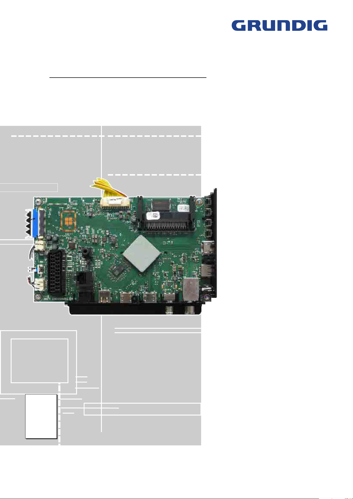
TV Service Manual
Service
Manual
NUR FÜR INTERNEN GEBRAUCH
FOR INTERNAL USE ONLY
Chassis G5
32 VLE 5620 BN PSN000
43 VLE 5620 BN PSP000
49 VLE 5620 BN PSQ000
Zusätzlich erforderliche Unterlagen für den Komplettservice
Additionally required Service Documents for the Complete Service
Sicherheit
Safety
Materialnr./Part No.
720108000001
Materialnummer / Part Number 720100573000
Änderungen vorbehalten / Subject to alteration
TCC 1216 MP • Prepared in Germany
http://www.grundig.com
Page 2

GRUNDIG Service Chassis G5
Es gelten die Vorschriften und Sicherheitshinweise
gemäß dem Service Manual "Sicherheit", Materialnummer 720108000001, sowie zusätzlich die eventuell abweichenden, landesspezifischen Vorschriften!
Inhaltsverzeichnis
Allgemeiner Teil
Allgemeine Hinweise .....................................................................1-2
Spezial-Funktionen
Geräte- und Display-Varianten
Servicehinweise
Technische Daten ..........................................................................1-6
Bedienhinweise
Service- und Sonderfunktionen
.................................. 1-2…1-46
........................................................................1-3
......................................................1-4
............................................................................1-4
.............................................................................1-8
...................................................1-46
Seite
Platinenabbildungen
und Schaltpläne
Chassisplatte ZG7190R-2 .............................................................2-1
– Blockschaltplan ..........................................................................2-5
– Übersicht....................................................................................2-6
– Netzteil .......................................................................................2-7
– IR/Keyboard ...............................................................................2-8
– HDMI..........................................................................................2-9
– LAN, SCART, SPDIF, USB .......................................................2-10
– Tuner ........................................................................................2-11
– PCMCIA-Interface ....................................................................2-12
– Scaler-SOC..............................................................................2-12
– RAM .........................................................................................2-13
– FLASH .....................................................................................2-13
– FRC .........................................................................................2-14
– Scaler-SOC/LVDS....................................................................2-15
– Verstärker .................................................................................2-16
LED-Konverter ZNL193-05
Netzteil ZNV194-03
IR/LED-Platte...............................................................................2-21
.................................. 2-1…2-21
..........................................................2-17
.....................................................................2-18
The regulations and safety instructions shall be valid
as provided by the "Safety" Service Manual, part
number 720108000001, as well as the respective
national deviations.
Table of Contents
General Section
General Notes ...............................................................................1-2
Special Functions
Product and Display Variants
Service Hints
Technical Data
Operating Hints
Service and Special Functions
.................................................................................1-4
...............................................................................1-6
.................................. 1-2…1-46
..........................................................................1-3
.........................................................1-4
............................................................................1-27
....................................................1-46
Page
Layout of the PCBs
and Circuit Diagrams
Chassis Board ZG7190R-2 ...........................................................2-1
– Block Circuit Diagram ................................................................2-5
– Overview ....................................................................................2-6
– Power Supply .............................................................................2-7
– IR/Keyboard ...............................................................................2-8
– HDMI..........................................................................................2-9
– LAN, SCART, SPDIF, USB .......................................................2-10
– Tuner ........................................................................................2-11
– PCMCIA Interface ....................................................................2-12
– Scaler-SOC..............................................................................2-12
– RAM .........................................................................................2-13
– FLASH .....................................................................................2-13
– FRC .........................................................................................2-14
– Scaler-SOC/LVDS....................................................................2-15
– Amplifier ...................................................................................2-16
LED Converter ZNL193-05
Power Supply ZNV194-03
IR/LED Board
..............................................................................2-21
......................... 2-1…2-21
..........................................................2-17
...........................................................2-18
Ersatzteillisten ...................................... 3-1…3-3
Allgemeiner Teil
Allgemeine Hinweise
Vor dem Öffnen des Gehäuses den Netzstecker ziehen!
Achtung: ESD-Vorschriften beachten
Leitungsverlegung
Bevor Sie die Leitungen und insbesondere die Masseleitungen lösen,
ist die Leitungs ver legung zu den einzelnen Baugruppen zu beachten.
Nach erfolgter Reparatur ist es notwendig, die Leitungsführung wieder
in den werkseitigen Zustand zu versetzen, um evtl. spätere Ausfälle
oder Störungen zu vermeiden.
Spare Parts Lists .................................. 3-1…3-3
General Section
General Notes
Before opening the cabinet disconnect the mains plug!
Attention: Observe the ESD safety regulations
Wiring
Before disconnecting any leads and especially the earth connecting
leads observe the way they are routed to the individual assemblies.
On completion of the repairs the leads must be laid out as originally
fitted at the factory to avoid later failures or disturbances.
1 - 2
Page 3
GRUNDIG Service Chassis G5
Durchführen von Messungen
Bei Messungen mit dem Oszilloskop an Halb leitern sollten Sie nur
Tast köpfe mit 10:1 - Tei ler verwen den. Außerdem ist zu beachten, dass
nach vorheriger Messung mit AC-Kopp lung der Koppelkondensator
des Oszillo skops auf geladen sein kann. Durch die Ent ladung über das
Messobjekt können Bau teile beschä digt werden.
Messwerte und Oszillogramme
Bei den in den Schaltplänen und Oszillogrammen angegebenen
Messwerten handelt es sich um Näherungswerte!
Austausch der Chassisplatte
Nach Austausch der Chassisplatte müssen alle Einstellungen im
Service Mode nach Tabelle "Grundeinstellwerte" (Punkt 1 im Kapitel
"Service- und Sonderfunktionen" auf Seite 1-46) eingestellt werden.
Spezial-Funktionen
Kindersicherung
Mit der Master-Pin 2356 kann der persönliche Pin geändert werden.
Hotel-Mode
Bei aktiviertem Hotel-Mode ist die maximale Lautstärke begrenzt und
das Menü "
spezifischen Einstellungen (z.B. Signalquelle, Sprache) werden beim
Einschalten des Gerätes auf die eingestellten Werte bei der Aktivierung
des Hotel-Modes zurückgesetzt.
Aufruf: MENU –> 8500 –> 4 "
Hotel
"
Hotel-Mode temporär ausschalten
Bei dieser Funktion ist der Hotel-Mode bis zum nächsten Ausschalten
(Standby) des Gerätes deaktiviert.
Aufruf: MENU –> 4658 –> EXIT –> MENU –> 1 2 43
OK
In dem zusätzlich erscheinenden Menü
sind folgende Einstellungen möglich:
–
Maximale Lautstärke
–
Einschaltlautstärke
–
Erstes Einschalten (Standby / Einschalten)
Cloning-Funktion
Mit dieser Funktion können folgende Daten auf den extern angeschlossenen USB-Speicher gesichert und zurück kopiert werden:
–
My Satellite List
–
Channel Set.
–
Service Einstellungen
–
User Set.
–
All(es)
–
Meine Programmliste
• Daten auf USB-Stick kopieren:
Leeren USB-Speicher anschließen (Formatierung FAT32) –> MENU
–> 1 2 43
tabelle
–> 1 2
All(es)
"
Erfolgreich
• Daten von USB-Stick in das Gerät zurück speichern:
USB-Stick anschließen –> MENU –> 1 2 43
1 2 "
1 2
Service Einstellungen, User Set, All(es)
starten mit –> am Ende wird "
Einstellungen > Quelle
" –> 1 2 "Ein".
–> 1 2 "TV" –> 4 "
Programmtabellen und Einstellungen der SAT-
Quelle - diese sind auch übertragbar auf weitere
Programmtabellen und Einstellungen der Si-
Kundenspezifische Einstellungen.
Für den Servicefall: sollte die defekte Chassis-
"Einstellungen" OK
" –> 4658 –> "
My Satellite List, Channel Set., Service Einstellungen., User Set,
oder
Meine Programmliste
" angezeigt.
Quelle" OK
USB to TV
Geräte gleicher Serie und Software.
gnalquellen - diese sind auch übertragbar auf
weitere Geräte gleicher Serie und Software.
Geräte-Einstellwerte der Service- und Sonder-
Funktionen ohne Display-Einstellwerte.
platte noch so weit funktionieren, können alle
Einstellwerte gespeichert werden um diese
dann in die neue Chassisplatte zu übertragen.
Programmtabellen sind mit dem
Editor
weitere Geräte, die
stützen.
Kopieren
–> 43 "
–> "
Copy Item
" ist nicht mehr änderbar. Alle kunden-
System Configuration
HOTEL-TV-EINSTELLUNGEN
am PC editierbar und übertragbar auf
–> 1 2 "
" –> 1 2
–> starten mit –> am Ende wird
Programmtabelle
" –> 1 2
HOTEL-TV-EINSTELLUNGEN
Meine Programmliste
Quelle" OK
TV to USB
" –> 4658 –> "
My Satellite List, Channel Set.
oder
Erfolgreich
" –> OK –> 43
"Einstellungen"
" –> OK
Programmlisten-
–> 43 "
–> 4 "
"Einstellungen" OK
Kopieren
Meine Programmliste
" angezeigt.
unter-
ProgrammCopy Item
–>
" –>
–>
Carrying out Measurements
When making measurements on semi-con duc tors with an oscillo scope,
ensure that the test probe is set to 10:1 dividing factor. If the previous
measurement was made on AC input, please note that the coupling
capacitor in the oscilloscope will be charged. Discharge via the item
being checked can damage the components.
Measured Values and Oscillograms
The measured values given in the circuit diagrams and oscillograms
are approximates!
Change of the Chassis Board
After changing the chassis board all settings in the service mode must
be done according to the table "Basic Settings" (point 1 in chapter
"Service and Special Functions" on page 1-46).
Special Functions
Parental Control
The personal pin can be changed with master pin 2356.
Hotel Mode
Maximum volume is limited and Menu "
able at activated hotel mode. After switch on the TV set, all user settings
(e.g. signal source, language) are set back to values by activation of
the Hotel Mode.
Call up: MENU –> 8500 –> 4 "
"
Hotel
" –> 1 2 "On".
Switching off the Hotel Mode temporarily
At this function the activated hotel mode is deactivated until the set
is switched off (standby).
Call up: MENU –> 4658 –> EXIT –> MENU –> 1 2 43 "
–> 1 2 "TV" –> 4 "
Following adjustment are available in the additionally menu
TV SETTINGS
–
Maximum Volume
–
Start-Up Volume
–
First Power (Standby / Power On)
Cloning Function
It is possible to copy following data to an external USB stick and back
to TV set:
– My Satellite List
– Channel Set.
– Service Set.
– User Set.
– All
– My Channel List
• Copy data to USB stick:
Connect empty USB memory (format FAT32) –> MENU –> 1 2 43
"Settings" OK
"
"
,
Channel Set., Service Set., User Set, All
• Copy data from USB stick into TV set:
Connect USB memory –> MENU –> 1 2 43
"
–> 4 "
Set, All
at the end.
User settings.
In case of service: If the defective chassis board
Copy
" –> 1 2
–> "
Success
Source" OK
Copy Item
or
My Channel List
HOTEL TV SETTINGS
:
Programme tables and settings of SAT signal
source - they are transferable into further TV
Programme tables and settings of signal sourc-
TV adjustments of service and special functions
–> 43 "
sets of same version and software.
es - they are transferable into further TV sets of
same version and software.
without panel values.
are still operate, it is possible to save all adjustments / settings and copy into new chassis
board.
Programme tables are editable with
List Editor
TV sets that support
–> 1 2 "
Source" OK
TV to USB
" is showing at the end.
" –> 1 2
–> 4 "
Channel Editor
My Satellite List, Channel Set., Service Set., User
–> start with –> "
Settings > Source
System Configuration
"–> OK
on the PC and transferable into further
–> 43 "
" –> 4658 –> "
Copy Item
or
My Channel List
My Channel List
Channel Editor
" –> 1 2
" is no change-
" –> OK –> 43
Settings" OK
" –> 4658 –>
My Satellite List,
–> start with
"Settings" OK
Copy
" –> 1 2
Success
" is showing
HOTEL
Programme
.
–> 1 2
USB to TV
1 - 3
Page 4
GRUNDIG Service Chassis G5
Geräte- und Display-Varianten
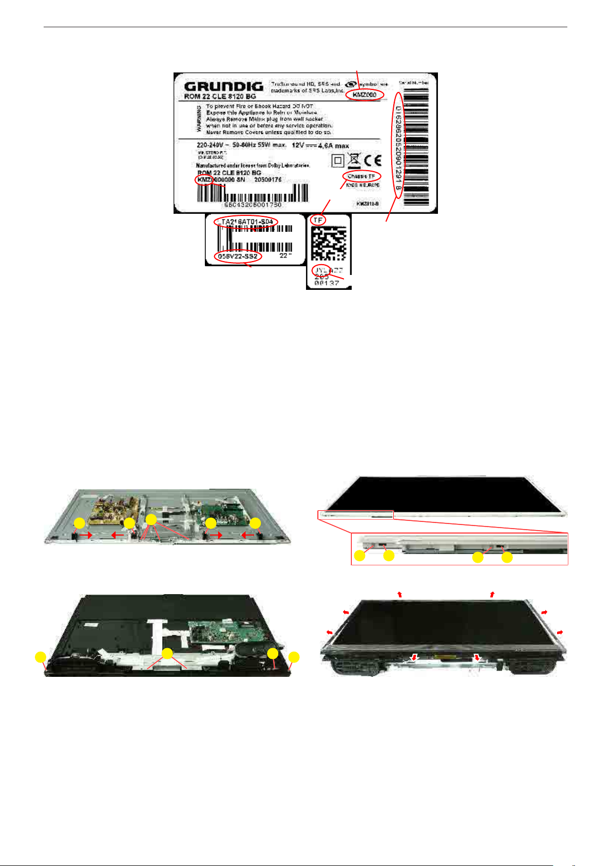
Display- und Product Code
Je nach Verfügbarkeit werden Displays verschiedener Hersteller eingebaut. Dies führt zu unterschiedlichen Chassis-Bestückungen, sowie zu Änderungen in der Software.
Bei Ersatzteilbestellungen und
Software-Updates achten Sie bitte
auf das eingebaute Display, sowie
auf den "Product Code". Angaben
dazu finden Sie auf der Geräterückseite. Sollte in der Ersatzteilliste
des Service Manuals Ihr "Product
Code" oder Ihre Display-Variante
nicht aufgeführt sein, können
Sie eine aktualisierte Version auf
dem GRUNDIG Service-Portal
"http://service.grundig.de" finden.
Überprüfen Sie vor PlatinenTausch, ob die Aufkleber der Platinen identisch sind (z.B. PCB Code).
Product Code
Display Type
Display Code
Servicehinweise
Abnehmen des BMS-Gehäusevorderteils (Backlight Modul System)
– Lautsprecher abnehmen.
– Fig. 1/3: Schrauben A herausdrehen.
– IR-LED-Baustein und Linse abnehmen.
– Fig. 1: Halter B in Pfeilrichtung schieben und abnehmen.
– Fig. 2/4: Gerät wie abgebildet auf eine weiche Unterlage legen.
– Fig. 2: Alle seitlichen Schrauben C herausdrehen.
– Fig. 2: Alle seitlichen Rasthaken D lösen und Gehäusevorderteil
abnehmen.
Fig. 4: Gehäusevorderteil beginnend an der Geräteunterseite vor-
sichtig so nach außen drücken, dass sich alle seitlichen Rasthaken
lösen. Gehäusevorderteil abnehmen.
Hinweis: Gerät nicht ohne Gehäusevorderteil umdrehen!
Product and Display Variants
Bestellnummer / Order Number
Chassis
Serialnummer /
Serial Number
PCB Code
Display- und Product Code
Depending on availability displays
of different manufacturer are built
in. This results in different chassis
mountings as well as a different
software. On spare parts orders as
well as software updates take care
of the fitted display as well as of the
"Product Code". Therefore you can
find information on the labels on the
rear side. If your "Product Code" or
display variant is not mentioned in
the spare parts list of the service
manual, please look for a current
version at the GRUNDIG service
portal "http://service.grundig.de".
Before changing any board please
check whether the labels on the
boards are identical (eg. PCB Code).
Service Hints
Remove the BMS Front Cabinet (Backlight Modul System)
– Remove the speakers.
– Fig. 1/3: Undo screws A.
– Remove IR/LED Board and Lens.
– Fig. 1: Push the holders B in arrow direction and remove it.
– Fig. 2/4: Lay device as shown on a soft pad.
– Fig. 2: Undo all screws at the side C.
– Fig. 2: Unlock all locking catches D and remove the front cabinet.
Fig. 4: Begins at below side to push front cabinet to outside, so that
unlock all locking catches. Remove front cabinet.
Note: Do not return the TV set without front cabinet!
B B BB
Fig. 1 Fig. 2
A A
Fig. 3 Fig. 4
A
A
A
C
CDD
1 - 4
Page 5
GRUNDIG Service Chassis G5
32"
1 - 5
Page 6
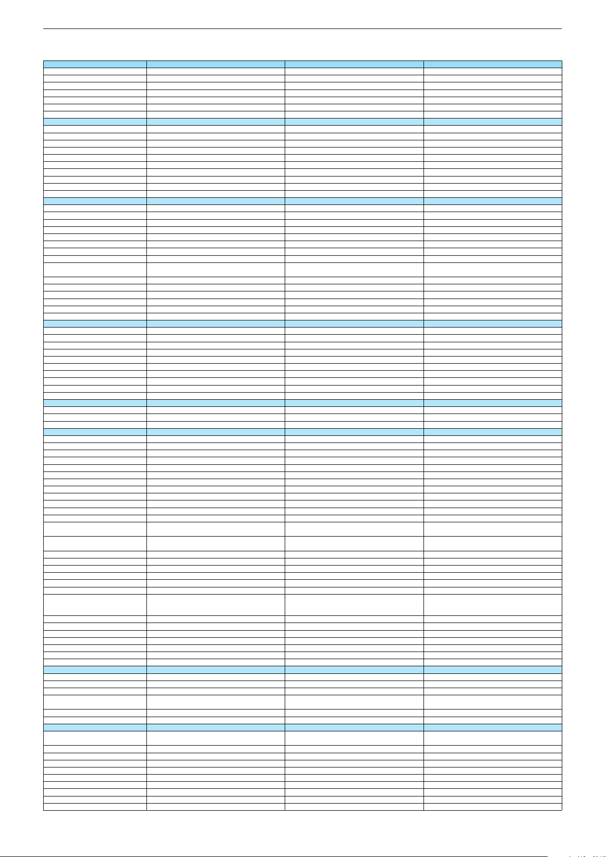
Technische Daten / Technical Data 32"
32 VLE 5620 BN 43 VLE 5620 BN 49 VLE 5620 BN
Order No.
Product Code
Country
Approbations
Remote control
EAN
Color
DISPLAY
Panel
Backlight
Wide-screen format
3D
2D/3D Converter
Local / Micro Dimming
Dynamic contrast
HDR / Wide Color Gamut
Panel Frequency
Physical display resolution max. pixel
PICTURE
Motion Picture Improvement (MEMC)
Motion Adaptive Deinterlacing
Line Flicker Reduction
Digital Color Transition Improv. (DCTI)
Digital Combfilter
Digital Luminance Trans. Improv. (DLTI)
Picture Noise Reduction
Preset picture modes
Aspect ratios (Format switching)
PIP
PAT: Split screen (PICTURE + TEXT)
PAP: Double Window (PICT. + PICT.)
Picture freezing
Zoom with point function
Blue Background
AUDIO
Mono/Stereo/Nicam
Loudspeaker
SRS
Dolby digital
Subwoofer
AVL (Audio Volume Level)
Equalizer
Space Sound Effect
Sound preset
Audio amplifier
CHASSIS
TV-Chassis
Scaler
Keyboard
ELECTRONIC
Stand by indicator
Programmable off timer
Programmable on timer
Zap / Swap
Programme Edit
Auto switch off
Programme memory TV/AV (opt.)
Teletext/Fasttext/Toptext
Teletext options
Hbb TV
HEVC/H.265
Childlock
Menue languages OSD
Game mode
Hotel mode
Digi Link
Miracast
Special feature
Wifi
DLNA
DLNA Supported Format
Internet Applications
Netflix
Smart Inter@ctive TV 4.0
Online SW Update
RC over IP
Bluetooth (TV)
Easy use remote control compatible
TUNING
Autom. Tuning System w. country select.
Manual fine tuning
Direct channel selection
Direct frequency selection
PAL/SECAM/BG/DK/I/L'/L
NTSC-Playback via Scart (3,58/4,43)
DVB reception
Fully compliant to
Autmatic/manual channel search
EPG (SI based)
EPG (Electronic Programme Guide)
- now/next
- scheduled
- Exdended Event Info
- Short Event Info
VPS - VBI insertion
Programme table
PSN000
PSN
PSP000
PSP
PSQ000
PSQ
IT; NO; SE; HR
CE
IT; NO; SE; HR
CE
TP6 (New)
40 13833-01657 1
TP6 (New)
40 13833-01658 8
IT; NO; SE; HR
CE
TP6 (New)
40 13833-01659 5
Black Black
32"/80 cm
DIRECT LED (BMS)
43"/108 cm
DIRECT LED (BMS)
/
/
Black
49"/123 cm
DIRECT LED (BMS)
/
DCR PLUS
/
DCR PLUS
/
50Hz
FHD (1.920x1.080)
50Hz
FHD (1.920x1.080)
3D DeInterlacer
3D DeInterlacer
DCR PLUS
/
50Hz
FHD (1.920x1.080)
3D DeInterlacer
3D
3D
User, Vivid, Natural, Movie, Sports
uto (WSS), 4:3 / 16:9 / 14:9 / Letterbox / Subtitle /
Panorama
User, Vivid, Natural, Movie, Sports
Auto (WSS), 4:3 / 16:9 / 14:9 / Letterbox / Subtitle /
Panorama
3D
User, Vivid, Natural, Movie, Sports
Auto (WSS), 4:3 / 16:9 / 14:9 / Letterbox / Subtitle /
Panorama
/ /
/ /
2 wide band at the front side
DTS-TruSurround
2 wide band at the front side
DTS-TruSurround
/ /
2 wide band at the front side
DTS-TruSurround
5 Band
5 Band
natural, music, speech, user
natural, music, speech, user
2 x 7/14W nominal/music power (R/L)
2 x 10/20W nominal/music power (R/L)
5 Band
natural, music, speech, user
2 x 10/20W nominal/music power (R/L)
G5
MSTAR ARM
G5
MSTAR ARM
4 Volume / Programm, ± keys, stand-by, source
4 Volume / Programm, ± keys, stand-by, source
Blue Led
Blue Led
/
/
G5
MSTAR ARM
4 Volume / Programm, ± keys, stand-by, source
Blue Led
/
100 Analog / 1000 T / 1000 T2 / 1000 C / 6000 S2 / AV
/ /
100 Analog / 1000 T / 1000 T2 / 1000 C / 6000 S2 / AV
/ /
1000 pages
1000 pages
100 Analog / 1000 T / 1000 T2 / 1000 C / 6000 S2 / AV
/ /
1000 pages
24 languages, D, GB, F, I, E, P, NL, DK, S, FIN, N, TR,
GR, PL, CZ, SK, SLO, H, RUS, RO, BG, HR, LT,EE
presets (user changeable) for sound and picture
in HDMI-, Component- and PC-mode
24 languages, D, GB, F, I, E, P, NL, DK, S, FIN, N, TR,
GR, PL, CZ, SK, SLO, H, RUS, RO, BG, HR, LT,EE
presets (user changeable) for sound and picture
in HDMI-, Component- and PC-mode
Simple hotel mode possible via service adjustment Simple hotel mode possible via service adjustment
24 languages, D, GB, F, I, E, P, NL, DK, S, FIN, N, TR,
GR, PL, CZ, SK, SLO, H, RUS, RO, BG, HR, LT,EE
presets (user changeable) for sound and picture
in HDMI-, Component- and PC-mode
Simple hotel mode possible via service adjustment
with headphone output and gyro function
with headphone output and gyro function
with headphone output and gyro function
full automatic sorting full automatic sorting
For cable tuning can be done by entering
the frequency (MHz) in digital search menu
For cable tuning can be done by entering
the frequency (MHz) in digital search menu
full automatic sorting
For cable tuning can be done by entering
the frequency (MHz) in digital search menu
EN 300 744 & revided NorDig II spec
(regarding DVB-T front end performance)
/ - ATS type sorting & LCN type sorting
EN 300 744 & revided NorDig II spec
(regarding DVB-T front end performance)
/ - ATS type sorting & LCN type sorting
8 days via DVB-T, DVB-T2, DVB-C, DVB-S2
8 days via DVB-T, DVB-T2, DVB-C, DVB-S2
If broadcasted
If broadcasted
If broadcasted
If broadcasted
If broadcasted
If broadcasted
EN 300 744 & revided NorDig II spec
(regarding DVB-T front end performance)
/ - ATS type sorting & LCN type sorting
8 days via DVB-T, DVB-T2, DVB-C, DVB-S2
If broadcasted
If broadcasted
If broadcasted
PDC based
full automatic sorting
PDC based
full automatic sorting
PDC based
full automatic sorting
Chassis G5GRUNDIG Service
1 - 6
Page 7
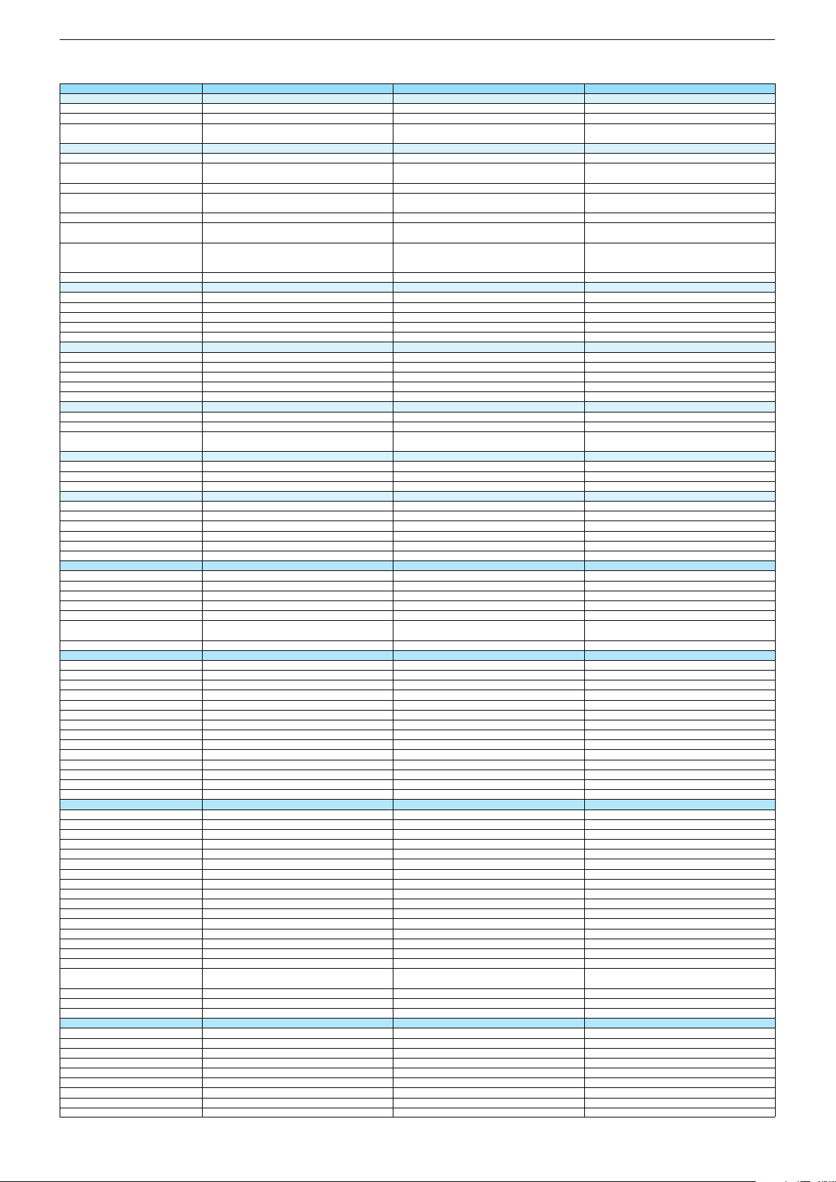
32 VLE 5620 BN 43 VLE 5620 BN 49 VLE 5620 BN
DVB-C Front end
Input frequency (MHz)
Imput level / Impedance
Demodulation / Symbol rate Ms/s
DVB-S2 Front end
Input frequency range
Signal level
Demodulation
Input symbol rate
DiseqC 1.2 support
LNB power & Polarization
FEC MODE
Unicable
DVB-T Front end
Input frequency (MHz) / Loop through
Input level / Impedance
Modulation
FEC Mode
Activ antenna support
DVB-T2 Front end
Input frequency range
Input level / Impedance
Modulation
FEC Mode
Activ antenna support
Video Decoder
MPEG profiles
Resolution
Picture formats
Audio Decoder
Profiles
AC 3 Output
Modes
Software
Service information processing
DVB subtitling
Over air download (OTA)
Last station memory
Favourite mode
Mute function
USB part
Recording
Divx + HD
Repeat
File browser
Video file resolution (max.)
Supported files
Supported subtitles
POWER SUPPLY / CABINET
Power voltage
Range of regulation
Power frequency
Power switch
Integrated supply
Plug-in AC adaptor
Energy class
Nominal Power Consumption
Stand-by Power Consumption
Networked Stand-by Power Consumption
Annual On-Mode Energy Consumption
Cabinet without stand (WxHxD)
Cabinet with stand (WxHxD)
Weight - Unpacked
REAR PANEL CONNECTIONS
Euro-AV-Socket AV1
S-Video
Camera-AV
LAN
YUV input / progressive
PC-input
PC-Audio in
HDMI 1.4 / 2.0
- MHL 2.0
- ARC
- HD ready including HDCP
Common Interface
Headphones
Digital Audio out optical (SPDIF)
Audio out
USB 2.0 / 3.0
Antenna for terrestrial reception
Antenna for satellite reception
DC-connector
Power supply plug
SUPPLIED ACCESSORIES
Wi-Fi Dongle
Remote control (incl. battery)
3D Glasses
Power cord
Instruction manual
Wall fixture (mm)
Stand
Stand Foot Distance
Cleaning tissue
47 - 862 VHF & UHF 47 - 862 VHF & UHF
47 - 70dbµV / 75 Ohm
QAM 16/32/64/128/256 demodulation support
(EN 300 429) 4,0…7,2 Msymbols/s
47 - 70dbµV / 75 Ohm
QAM 16/32/64/128/256 demodulation support
(EN 300 429) 4,0…7,2 Msymbols/s
950 MHz to 2150 MHz 950 MHz to 2150 MHz
47 - 862 VHF & UHF
47 - 70dbµV / 75 Ohm
QAM 16/32/64/128/256 demodulation support
(EN 300 429) 4,0…7,2 Msymbols/s
950 MHz to 2150 MHz
-25 to -80dBm (Only for DVB-S)
-25 to -70dBm (Only for DVB-S2)
QPSK, 8PSK
-25 to -80dBm (Only for DVB-S)
-25 to -70dBm (Only for DVB-S2)
QPSK, 8PSK
1 - 45 Msps for DVB-S
5 - 30 Msps for DVB-S2
1 - 45 Msps for DVB-S
5 - 30 Msps for DVB-S2
13/18V Selection / Vertical
22 KHz generation / Overload Protection
Auto - QPSK-S: 1/2, 2/3, 3/4, 3/5, 5/6, 8/9, 9/10
QPSK-S2: 1/2, 2/3, 3/4, 3/5, 4/5, 5/6, 8/9, 9/10
8PSK: 2/3, 3/4, 3/5, 5/6, 8/9, 9/10
13/18V Selection / Vertical
22 KHz generation / Overload Protection
Auto - QPSK-S: 1/2, 2/3, 3/4, 3/5, 5/6, 8/9, 9/10
QPSK-S2: 1/2, 2/3, 3/4, 3/5, 4/5, 5/6, 8/9, 9/10
8PSK: 2/3, 3/4, 3/5, 5/6, 8/9, 9/10
-25 to -80dBm (Only for DVB-S)
-25 to -70dBm (Only for DVB-S2)
QPSK, 8PSK
1 - 45 Msps for DVB-S
5 - 30 Msps for DVB-S2
13/18V Selection / Vertical
22 KHz generation / Overload Protection
Auto - QPSK-S: 1/2, 2/3, 3/4, 3/5, 5/6, 8/9, 9/10
QPSK-S2: 1/2, 2/3, 3/4, 3/5, 4/5, 5/6, 8/9, 9/10
8PSK: 2/3, 3/4, 3/5, 5/6, 8/9, 9/10
177 - 862 VHF & UHF /
-80 to 20/dBm / 75 Ohm
177 - 862 VHF & UHF /
-80 to 20/dBm / 75 Ohm
COFDM 2/8 QPSK 16/64 QAM
1/2, 2/3, 3/4, 5/6, 7/8
COFDM 2/8 QPSK 16/64 QAM
1/2, 2/3, 3/4, 5/6, 7/8
177 - 862 VHF & UHF
-75 to -35dBm / 75Ohm
177 - 862 VHF & UHF
-75 to -35dBm / 75Ohm
177 - 862 VHF & UHF /
-80 to 20/dBm / 75 Ohm
COFDM 2/8 QPSK 16/64 QAM
1/2, 2/3, 3/4, 5/6, 7/8
177 - 862 VHF & UHF
-75 to -35dBm / 75Ohm
QPSK, 16QAM, 64QAM, 256QAM
LDPC + BCH 1/2, 3/5, 2/3, 3/4, 4/5, 5/6
QPSK, 16QAM, 64QAM, 256QAM
LDPC + BCH 1/2, 3/5, 2/3, 3/4, 4/5, 5/6
MP@ML, MP@HL, MPEG4 AVC H.264 [email protected]
576i, 576p, 720p, 1080i, 1080p
MP@ML, MP@HL, MPEG4 AVC H.264 [email protected]
576i, 576p, 720p, 1080i, 1080p
Auto (WSS), 4:3 / 14:9 / 16:9 / Panorama / Letterbox /
Subtitle
Auto (WSS), 4:3 / 14:9 / 16:9 / Panorama / Letterbox /
Subtitle
QPSK, 16QAM, 64QAM, 256QAM
LDPC + BCH 1/2, 3/5, 2/3, 3/4, 4/5, 5/6
MP@ML, MP@HL, MPEG4 AVC H.264 [email protected]
576i, 576p, 720p, 1080i, 1080p
Auto (WSS), 4:3 / 14:9 / 16:9 / Panorama / Letterbox /
Subtitle
MPEG 4 , MPEG 2 layer I & II
SP/DIF
MPEG 4 , MPEG 2 layer I & II
SP/DIF
Mono, Dual Mono, Stereo, Joint Stereo
Mono, Dual Mono, Stereo, Joint Stereo
Dynamic PMT
Dynamic PMT
DVB enhanced profile
from stand-by, as TV
DVB enhanced profile
from stand-by, as TV
MPEG 4 , MPEG 2 layer I & II
SP/DIF
Mono, Dual Mono, Stereo, Joint Stereo
Dynamic PMT
DVB enhanced profile
from stand-by, as TV
4x free
4x free
1920 x 1080
1920 x 1080
4x free
1920 x 1080
.mp3, .m4a, .aac, .jpg, .jpe, . bmp, .png, .mov, .mpg,
.mpe, .vob, .dat, .trp, .ts, .avi, .mp4, .mkv, .div
SRT, SSA, ASS, SMI, Video SUB
.mp3, .m4a, .aac, .jpg, .jpe, . bmp, .png, .mov, .mpg,
.mpe, .vob, .dat, .trp, .ts, .avi, .mp4, .mkv, .div
SRT, SSA, ASS, SMI, Video SUB
220-240V 220-240V
50-60Hz 50-60Hz
Tact switch
Tact switch
.mp3, .m4a, .aac, .jpg, .jpe, . bmp, .png, .mov, .mpg,
.mpe, .vob, .dat, .trp, .ts, .avi, .mp4, .mkv, .div
SRT, SSA, ASS, SMI, Video SUB
220-240V
50-60Hz
Tact switch
A
A+
40,1W
0,3W
53,1W
0,3W
N/A
59kWh
N/A
78kWh
738,7 x 474,6 x 78,3mm
738,7 x 505 x 249,6mm
970,3 x 609,4 x 76,4mm
970,3 x 636 x 249,6mm
A+
67,1W
0,3W
N/A
98kWh
1105,9 x 682 x 76,9mm
1105,9 x 713 x 249,6mm
ca. 6,0kg ca. 9,4kg
Full wired
Via Scart
Full wired
Via Scart
Via Scart
Via Scart
via Scart
via Adapter
via Scart
via Adapter
ca. 11,8kg
Full wired
Via Scart
Via Scart
via Scart
via Adapter
via Adapter
3 / 0
via Adapter
3 / 0
via HDMI1
via HDMI4
via HDMI1
via HDMI4
via HDMI
(CI+)
via HDMI
(CI+)
3.5mm jack
optical
3.5mm jack
optical
via Adapter
3 / 0
via HDMI1
via HDMI4
via HDMI
(CI+)
3.5mm jack
optical
via Headphone
2 / 0
via Headphone
2 / 0
1 x Coaxial-socket for TV-tuner-in,
according to DIN 45325
1 x F-connector
1 x Coaxial-socket for TV-tuner-in,
according to DIN 45325
1 x F-connector
via Headphone
2 / 0
1 x Coaxial-socket for TV-tuner-in,
according to DIN 45325
1 x F-connector
TP6 (New)
TP6 (New)
Prepared for VESA standard adaptor 100 x 150Prepared for VESA standard adaptor 200 x 200
580mm
757mm
TP6 (New)
Prepared for VESA standard adaptor 300 x 200
828mm
Chassis G5GRUNDIG Service
1 - 7
Page 8
Bedienhinweise Dieses Kapitel enthält Auszüge aus der Bedienungsanleitung. Weitergehende Informationen entnehmen Sie bitte der gerätespezifischen Bedienungsanleitung, die Sie unter www.grundig.de, Menüpunkt Downloads/Bedienungsanlei-
tungen herunterladen können.
Chassis G5GRUNDIG Service
1 - 8
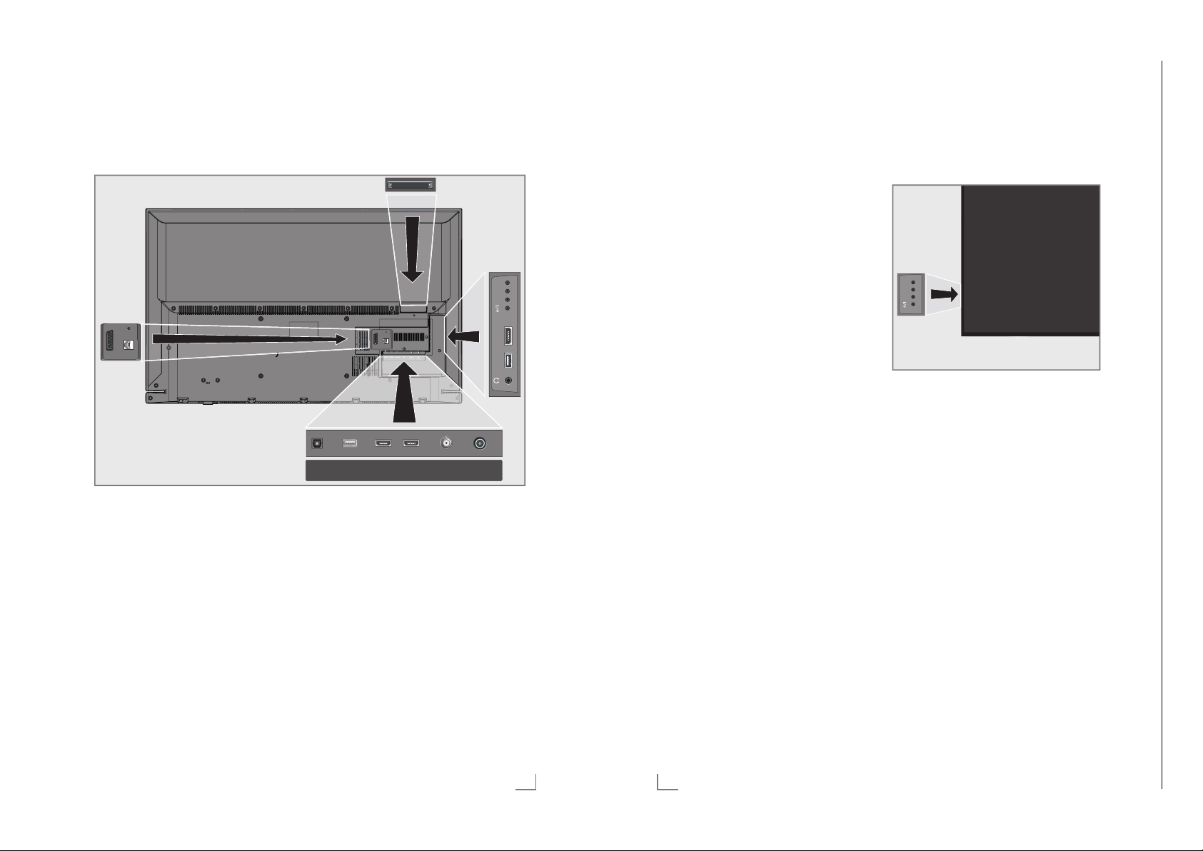
AUF EINEN BLICK
-------------------------------------------------------------------------------------------
Anschlüsse des Fernsehgerätes
SERVICE
AV / S-VHS/COMPONENT
LAN
LAN Buchse zum Anschließen
AV / S-VHS / COMPONENT
Euro/AV-Buchse
SERVICE Buchse nur für Service.
Optic Out Tonsignal-Ausgang (op-
an das Heimnetzwerk über
LAN-Kabel.
(FBAS-Signal, RGB-Signal);
Bildsignal-Buchse für
S-Video-Camerarecorder;
Bildsignal-Eingang (YUVSignal über Scart/YUV
Adapter).
tisch, PCM/Dolb
y DigitalSignale).
Zum Anschluss digitaler
AV-Verstärker oder AVReceiver.
SERVICE
AV / S-VHS/COMPONENT
LAN
USB1 HDMI1 +V/P-
Optic Out SATELLITE
HDMI2HDMI3(ARC)USB(HDD)
13/18V
max.500mA
ANT-IN
5V
max.50mA
USB(HDD) USB-Buchse für externe
Datenträger ohne eigene
Stromversorgung für
PVR-Funktion;
Anschluss für drahtlose
USB-Tastatur/Maus.
HDMI3 (ARC) HDMI-Ton-/Bildsignal-
Eingang (AR
C).
HDMI2 HDMI-Ton-/Bildsignal-
Eingang.
SATELLITE Antennenbuchse für die
Satellitenantenne (DVB-S).
ANT-IN Antennenbuchse für DVB-
T
, DVB-C und analoge
Antenne.
U Kopfhörerbuchse
(3,5-mm-Klinkenstecker);
Buchse für TonsignalAusgang über einen handelsüblichen Adapter.
DEUTSCH
13
AUF EINEN BLICK
-------------------------------------------------------------------------------------------
USB1 USB-Buchse für externe
Datentr
äger ohne eigene
Stromversorgung für
PVR-Funktion;
Anschluss für drahtlose
USB-Tastatur/Maus.
HDMI1 HDMI-Ton-/Bildsignal-
Eingang (MHL).
CI
Common InterfaceSteck-
platz.
14
DEUTSCH
Bedienelemente des Fernsehgerätes
+V/P-
Fernsehgerät in Bereitschaft schalten
1 »8/I« Schaltet das Fernsehgerät ein und
wieder in Bereitschaft (Stand-by).
Lautstärke ändern oder Programm
wechseln
1 »V/P« Vorwahltaste für Lautstärke oder
Programmwahl.
2 »–« Lautstärke verringern;
Pr
ogrammwahl abwärts.
3 »+« Lautstärke vergrößern;
ogrammwahl aufwärts.
Pr
Page 9
Chassis KPGRUNDIG Service
1 - 9
AUF EINEN BLICK
Chassis G5GRUNDIG Service
1 - 9
-------------------------------------------------------------------------------------------
AUF EINEN BLICK
-------------------------------------------------------------------------------------------
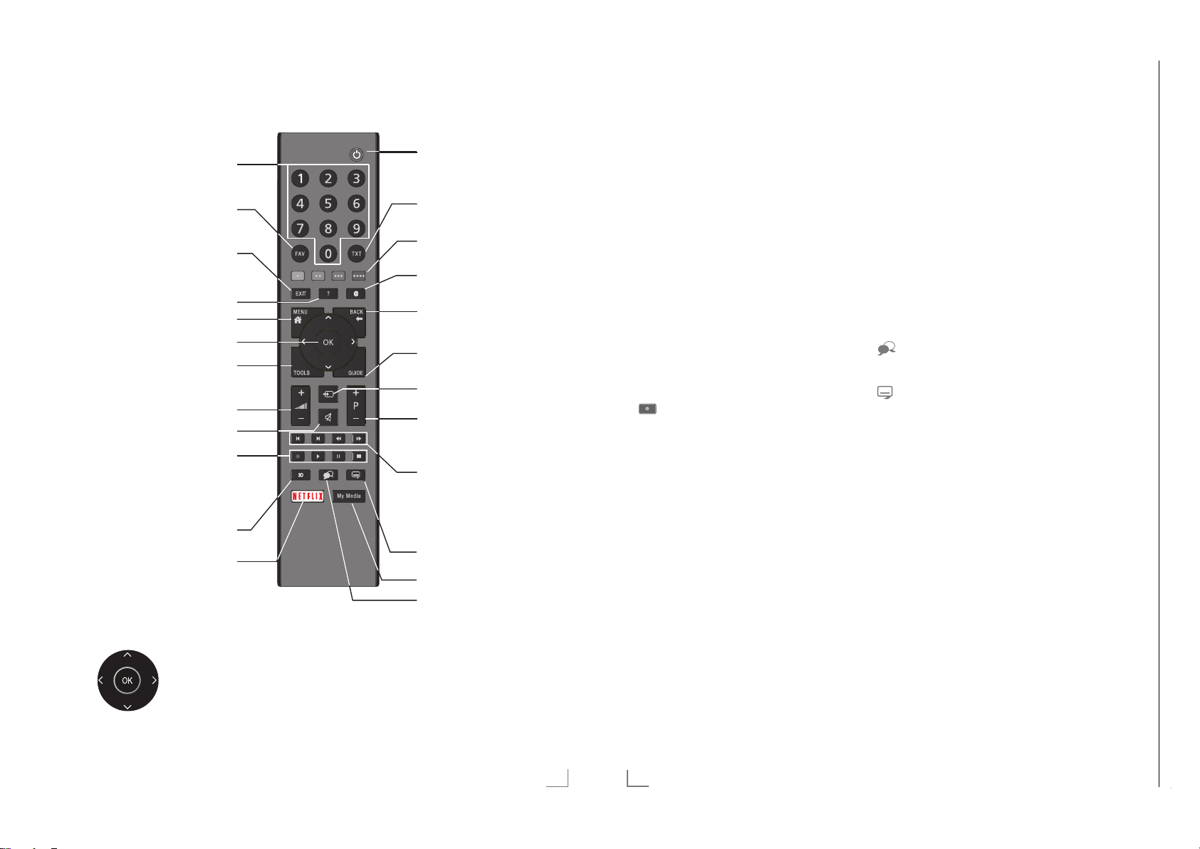
Fernbedienung – Hauptfunktionen
Einschalten aus Stand-by;
Programm-Direktwahl
Favoritenlisten
Menüs und Applikationen
beenden
Informationen anzeigen
Hauptmenü
Programmliste
Werkzeuge: Funktionen
und Einstellungen
Lautstärke
Stummschalten
Aufnehmen, Abspielen,
Pause, Stopp (nur digitale
Fernseh-Programme);
Videotext auf halbem
Bildschirm
Ohne Funktion
Netflix Applikationen
aufrufen.
Ein/Bereitschaft(Stand-by).
Videotext aufrufen/ausschalten
Funktionen entsprechend
Bildschirmhilfe, HbbTV
„Meine Apps“-Menü
Zapp-Funktion;
in den Menüs eine Menüebene zurück
schalten
Programmführer
Signalquelle
Einschalten aus Stand-by;
nächstes/vorheriges
Programm
Nächstes/vorheriges Bild/
Kapitel;
nächster/vorheriger Titel
Untertitel wählen
Medienplayer
Tonkanal wählen
Fernbedienung – alle Funktionen
(rot), Wählen/aktivieren Seiten im
y
(grün) Videotext.
yy
(gelb) Wählen/aktivieren unterschiedliche
yyy
(blau) Funktionen in den Menüs.
yyyy
5 Schaltet im Videotext auf doppelte
6 Aktualisiert eine Videotextseite;
3
4
8 Startet die Wiedergabe einer Sen-
Zeichengröße;
wählt im Medienplayer den vorherigen Titel/das nächste Bild.
wählt im Medienplayer den
nächsten Titel/das vorherige Bild.
Stoppt das Umblättern von Seiten
im Videotext;
startet im Medienplayer den
schnellen Rücklauf.
Deckt Antworten im Videotext auf;
startet im Medienplayer den
schnellen Vorlauf.
Startet die Aufnahme
(nur bei digitalen Fernsehprogrammen, die Aufnahme erfolgt auf einem
externen Datenträger).
dung vom externen Datenträger;
startet die Wiedergabe einer Datei
vom Medienserver.
! Timeshift-Betrieb (nur bei digitalen
7 Teilt die Bildanzeige im Videotext;
Fernsehprogrammen und wenn ein
externer Daten träger angeschlossen
ist);
Pause bei der Wiedergabe einer
Sendung vom externen Datenträger
oder vom Medienplayer;
Pause beim Abspielen einer Datei
vom Medienserver.
beendet die Wiedergabe einer
Sendung vom externen Datenträger
oder vom Medienplayer.
Beendet die Aufnahme oder die
Wiedergabe im Timeshift-Betrieb.
Beendet die Wiedergabe einer Datei vom Medienserver.
Wählt unterschiedliche Audio-
sprachen (nur bei digitalen
Fernsehprogrammen).
Wählt unterschiedliche Untertitel
(nur bei digitalen FernsehProgrammen).
Hinweis:
7
Ihr Fernsehgerät kann von einem Apple
iPhone oder von Android Smartphones
fernbedient werden. Die Möglichkeiten
sind abhängig vom Funktionsumfang des
Fernsehgerätes.
Voraussetzung dafür ist, Sie laden die
kostenlose Applikation »GRUNDIG TV
Remote« vom Apple App Store oder vom
Google play (Android Market) und installieren diese auf Ihrem Apple iPhone/Smartphone.
Navigieren in den Menüs
Bewegen den Cursor in den
Menüs nach oben und unten.
Bewegen den Cursor in den
Menüs nach link
Aktiviert verschiedene Funk-
tionen und speichert Funktionen/Einstellungen.
s und rechts.
DEUTSCH
15
16
DEUTSCH
Page 10

Chassis G5GRUNDIG Service
1 - 10
ERSTINSTALLATION
------------------------------------------------------------------------------------
ERSTINSTALLATION
------------------------------------------------------------------------------------
Erstinstallation durchführen
1 Fernsehgerät mit »8«, »1…0« oder »P+«
oder »P-« aus Stand-by einschalten.
–
Bei der ersten Inbetriebnahme wird das
Menü »Menüsprache« eingeblendet.
Smart Inter@ctive 4.0
Bitte whlen Sie Ihre gewünsche Menüspache aus
Menüsprache
Česky Dansk Deutsch English Espanol
Hrvatski Italiano Magyar Nederlands Norsk Polski Português
Pyccкий Româneşte Slovenščina Eesti Suomi Svenska Бългaрски
Slovenčina Lietuviu Türkçe
Navigieren
Deutsch
Besttigen
Hilfe:
7
Wird dieses Menü nicht angezeigt, setzen
Sie das Fernsehgerät auf seine Werkseinstellungen zurück (siehe Seite 76).
2 Gewünschte Menüsprache mit »
»
V
« oder »Λ« wählen und mit »OK« be-
stätigen.
–
Ein Hinweis zu den Grundeinstellungen
wird eingeblendet.
3 Grundeinstellungen mit »OK« starten.
4 Das Land, in dem das Fernsehgerät
betrieben wird, mit »
»
Λ
« wählen und mit »OK« bestätigen.
– Das Menü »Benutzermodus« wird ein-
geblendet, die Option »Home Modus« ist
markiert.
5 Die Option »Home Modus« mit »OK«
tätigen;
bes
oder
die Option »Brilliant« mit »
wählen und mit »OK« bestätigen
– Die bei der Option »Home Modus«
verwen deten Einstellungen sparen
Energie .
–
Die Option »Brilliant« dient zu Demonstrationszwecken der Gerätefunk tionen
im Fachhandel und bietet optimale Bildund Tonqualität, verbraucht jedoch mehr
Leistung.
Eλληvıκά
«, »>«,
<
«, »>«, »V« oder
<
V
« oder »Λ«
Français
6 Die benötigte Option »Standfuß« oder
Wandmontage« mit »
»
V
« oder »Λ« wäh-
len und mit »OK« bestätigen.
Hinweis:
7
Die Toneinstellungen werden je nach Auf-
stellungsart »Standfuß« oder »Wandmontage« optimal eingestellt.
7 Einstellung mit »OK« bestätigen.
– Das Menü »Übersicht« wird eingeblendet.
8 Den nächsten Bedienschritt mit »
(blau) an
wählen.
yyyy
«
– Das Menü »Zubehör« wird eingeblendet.
9 Wenn für das Fernsehgerät Zubehör ver-
w
endet wird und es bereits angeschlossen
wurde, in diesem Menü die notwendigen
Einstellungen durchführen.
V
Zubehör mit »
Einstellung mit »
10 Den nächsten Bedienschritt mit »
(blau) an
« oder »Λ« wählen und
« oder »>« wählen.
<
wählen.
yyyy
«
Hinweis:
7
Wenn das Fernsehgerät am Heimnetzwerk
angemeldet werden soll,
– weiter bei Punkt 12 für eine automatische
AN-Verbindung, oder
L
– weiter bei Punkt 17 für eine automatische
WL
AN Verbindung.
Hinweis:
7
Wird keine Anmeldung am Heimnetzwerk
benötigt, mit »
überspr
ingen. Einstellung bei Pkt. 25, 30
« (blau) die Einstellung
yyyy
oder 35 fortsetzen.
Anmeldung am Heimnetzwerk – mit
einem LAN-Kabel
11 Die Option »Verbindungstyp ändern« mit
»OK« aktivieren.
V
12 Zeile »Kabel« mit »
« oder »Λ« wählen
und mit »OK« bestätigen.
Hinweis:
7
Die Einstellungen für eine manuelle LAN-
Verbindung finden Sie auf Seite 89.
13 Anmeldung an das Heimnetzwerk mit »y«
(r
ot) starten.
– Die Meldung »Verbinde... Bitte warten«
wird eingeblendet.
14 Wenn die Meldung erlischt, mit »yy« (grün)
erbindung zum Netzwerk prüfen.
die V
– Anzeige: »Testen ... Bitte warten«, nach
erfolgreicher Anmeldung: »Verbindung mit
Gateway: Erfolgreich« und »Internetverbindung: Erfolgreich«.
15 Den nächsten Bedienschritt mit »
yyyy
«
(blau) anwählen.
Hinweis:
7
Die Suche nach Fernsehprogrammen setzen
Sie fort bei:
– Punkt 25 für DVB-S Empfang;
–
Punkt 30 für DVB-C Empfang;
–
Punkt 35 für DVB-T Empfang.
Anmeldung am Heimnetzwerk – über
WLAN – automatisch, mit Eingabe des
Netzwerk-Kennwortes
16 Die Option »Verbindungstyp ändern« mit
»OK« aktivieren.
V
17 Zeile »Kabellos« mit »
« oder »Λ« wählen
und mit »OK« bestätigen.
18 Die Meldung »Möchten Sie WLAN ein-
schalten« bes
»
« die Schaltfläche »Ja« anwählen und mit
>
»OK« bestätigen.
tätigen, dazu mit »
« oder
<
19 Zeile »Netzwerk wählen« mit »
»
Λ
« wählen und mit »OK« bestätigen.
V
« oder
– Das Menü »Netzwerk wählen« wird ein-
geblendet, die vorhandenen Netzwerke
werden gesucht und angezeigt.
V
20 Das gewünschte Netzwerk mit »
»
Λ
« wählen und mit »OK« bestätigen.
« oder
– Das »Kennwort« Menü wird eingeblendet.
21 Das erste Zeichen/Ziffer des benötigten
V
ennworts mit »
K
«, »Λ«, »<« und »>«
wählen und mit »OK« zur nächsten Einga-
telle schalten.
bes
– Mit »Shift« ° »OK« kann zwischen
Gr
oßbuchstaben/Nummern und Kleinbuchstaben/Sonderzeichen umgeschaltet
werden.
– Zum Löschen von Zeichen/Ziffern die
Schaltfläche »Del« wählen und mit »OK«
bestätigen.
22 Kennwort mit »yy« (grün) bestätigen.
– Die Meldung »Verbinde... Bitte warten«
wird eingeblendet, danach »Verbindung
mit Gateway: Erfolgreich«.
23 Wenn die Meldung erlischt, mit »yy« (grün)
erbindung zum Netzwerk prüfen.
die V
– Anzeige: »Testen ... Bitte warten«, nach
erfolgreicher Anmeldung »Verbindung mit
Gateway: Erfolgreich« und »Internetverbindung: Erfolgreich«.
24 Den nächsten Bedienschritt mit »
yyyy
«
(blau) anwählen.
Hinweis:
7
Die Suche nach Fernsehprogrammen setzen
Sie fort bei:
– Punkt 25 für DVB-S Empfang;
–
Punkt 30 für DVB-C Empfang;
Punkt 35 für DVB-T Empfang.
–
DEUTSCH
19
20
DEUTSCH
Page 11

ERSTINSTALLATION
Chassis G5GRUNDIG Service
1 - 11
------------------------------------------------------------------------------------
ERSTINSTALLATION
------------------------------------------------------------------------------------
Programme (DVB-S) einstellen
Hinweis:
7
Wenn bei »Menüsprache wählen« die Op-
tion »Deutsch« und bei »Land« die Option
»Deutschland« oder »Österreich« gewählt
wurde, gibt es im Menü »Betreiberauswahl«
mehrere Möglichkeiten:
– »Astra Schnell«: Schnelle Programmsuche
(ca. 30 Sekunden) nach vorsortieren
Fernsehprogrammen (ca. 800 Fernsehprogramme), empfohlen für Deutschland und
Österreich.
– »Komplett«: Vollständiger Programmsuch-
lauf (bis zu 10 Minuten) nach vordefinierten Transponderfrequenzen des Satelliten
Astra mit vorsortierter Programmtabelle
(ca. 1300 Fernsehprogramme), empfohlen für alle Länder.
– »Sky«: diese Option ist nur für Benut-
zer geeignet, die Kunde beim Pay TV
Anbieter „Sky“ sind. (nicht vorhanden für
Österreich und die Schweiz.)
25 Die Option »Satellit (DVB-S/S2)« mit »
oder »
Λ
« wählen und mit »OK« bestätigen.
V
26 Die Option »Astra Schnell« mit »
»
Λ
« wählen und mit »OK« bestätigen.
« oder
– Der Satellit Astra 19,2° Ost ist vor-
eingestellt.
27 Die Schaltfläche »Weiter« mit »
tätigen.
be s
yyyy
« (blau)
Hinweise:
7
Auswahl treffen, ob nur nach Fernsehpro-
grammen (TV), nur nach Radioprogrammen
(Radio) oder nach beidem (Radio + TV) gesucht werden soll. Dazu mit »
V
« oder »Λ«
die Option »TV Digital« oder »Radio Digital«
anwählen und mit »OK« das „Häkchen“
entfer
nen oder setzten.
7
Auswahl treffen, ob nur nach unverschlüssel-
ten Programmen oder nur nach verschlüsselten Programmen »
»
« die Option »Frei« oder »Verschlüsselt«
>
anwählen und mit »OK« das „Häkchen“
entfer
nen oder setzten.
V
«, »Λ«, »<« oder
28 Suchlauf mit »y« (rot) starten.
– Das Menü »Digital Suche« wird ein-
geblendet, die Suche nach Programmen
beginnt.
– Der Suchlauf ist beendet, wenn die Mel-
dung »Suche ist abgeschlossen« erscheint.
29 Zur Programmtabelle mit »OK« schalten.
V
«
Programme (DVB-C) einstellen
30 Die Option »Kabel (DVB-C)« mit »V« oder
»
Λ
« wählen und mit »OK« bestätigen.
V
31 Die Zeile »Suchlauf nach« mit »
»
Λ
« wählen. Die gewünschte Option
(»Schnell« oder »Komplett«) mit »
»
« wählen.
>
– Die Suchfunktion »Schnell« stellt die
« oder
« oder
<
Programme nach den Informationen ihres
Kabelbetreibers im Übertragungssignal
ein.
– Wird die Option »Komplett« gewählt,
wird der gesamte Frequenzbereich durchsucht. Die Suche kann mit dieser Option
sehr lange dauern. Diese Option wird
em pfohlen, wenn der Kabelbetreiber den
Suchtyp »Schnell« nicht unterstützt.
32 Die Schaltfläche »Weiter« mit »
yyyy
« (blau)
be stätigen.
Hinweis:
7
Auswahl treffen, ob nach digitalen oder
nach analogen Fernsehprogrammen
gesucht werden soll. Dazu mit »
»
Λ
« die Option »Digital« oder »Analog«
V
« oder
anwählen und mit »OK« das „Häkchen“
entfer
nen oder setzen.
33 Suchlauf mit »y« (rot) starten.
– Das Menü »Digital Suche« wird ein-
geblendet, die Suche nach Programmen
beginnt.
– Der Suchlauf ist beendet, wenn die Mel-
dung »Suche ist abgeschlossen« erscheint.
34 Zur Programmtabelle mit »OK« schalten.
Programme (DVB-T) einstellen
35 Die Option »Terrestrisch (DVB-T/T2)« mit
»
V
« oder »Λ« wählen und mit »OK«
bestätigen.
Achtung:
7
Die Antennenspannung (5V ) darf nur
einge schaltet werden, wenn die angeschlossene Antenne eine aktive Zimmerantenne
mit Signalverstärker ist und diese nicht
schon selbst über ein Steckernetzteil (oder
ähnliches) mit Spannung versorgt wird.
Ansonsten kann es zu einem Kurzschluss
oder zur Zerstörung der Antenne kommen!
36 Zeile »Aktivantenne« mit »
V
« oder »Λ«
wählen.
Antennenspannung für die Antenne mit »
oder »
« einschalten (»Ein«).
>
V
37 Zeile »Weiter« mit »
« oder »Λ« wählen
und mit »OK« be stätigen.
Hinweis:
7
Auswahl treffen, ob nach digitalen oder
nach analogen Fernsehprogrammen
gesucht werden soll. Dazu mit »
»
Λ
« die Option »Digital« oder »Analog«
V
« oder
anwählen und mit »OK« das „Häkchen“
entfer
nen oder setzen.
38 Suchlauf mit »y« (rot) starten.
– Das Menü »Digital Suche« wird ein-
geblendet, die Suche nach Programmen
beginnt.
– Der Suchlauf ist beendet, wenn die Mel-
dung »Suche ist abgeschlossen« erscheint.
39 Zur Programmtabelle mit »OK« schalten.
«
<
DEUTSCH
21
22
DEUTSCH
Page 12
ERSTINSTALLATION
Chassis G5GRUNDIG Service
1 - 12
------------------------------------------------------------------------------------
ERSTINSTALLATION
------------------------------------------------------------------------------------
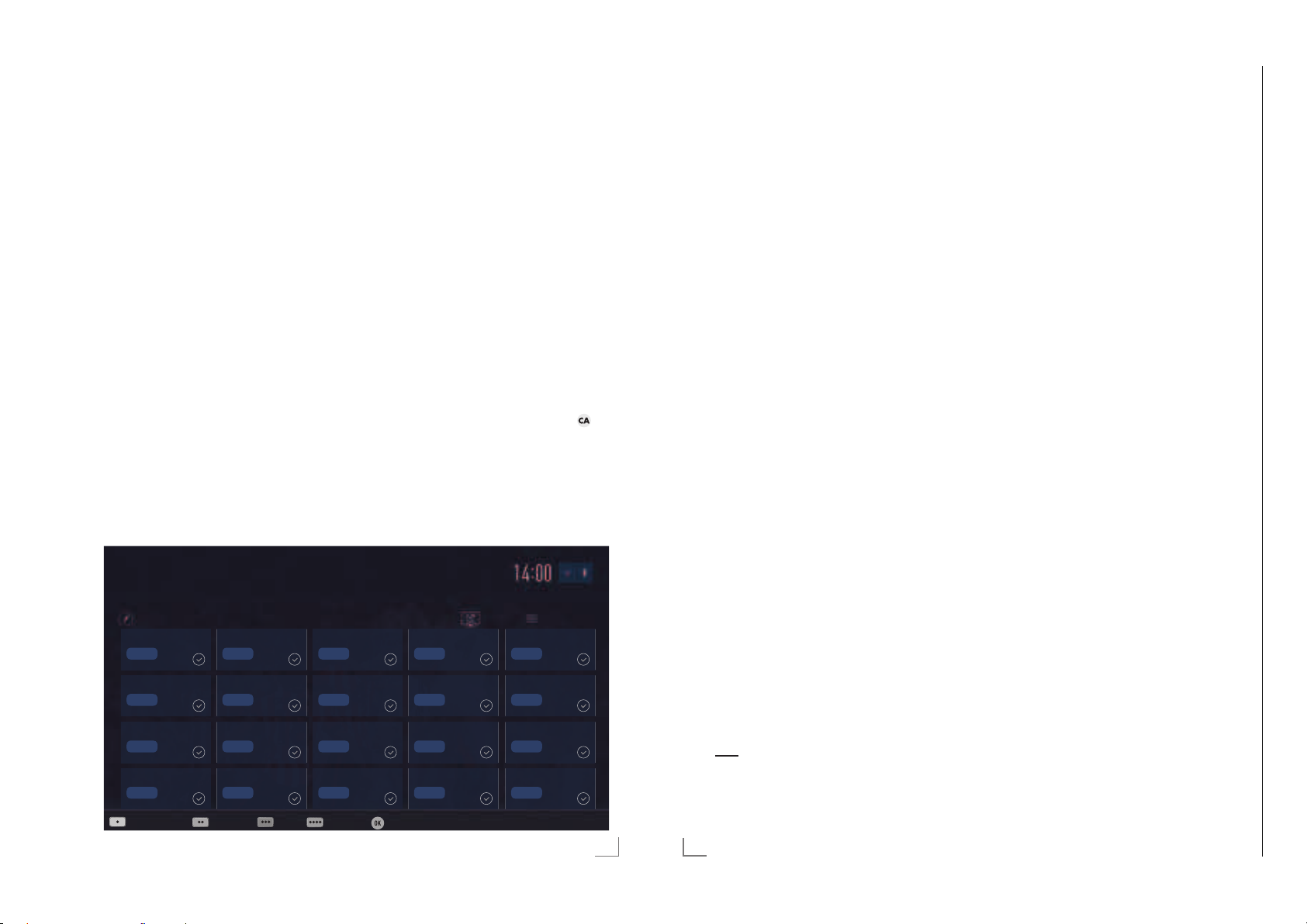
Programmtabelle für die
digi talen Programme ändern
Programme die über den Suchlauf gefunden
wurden, werden in der »Programmtabelle« gespeichert.
In der Programmtabelle können Sie nicht benötigte Programme löschen, die Reihenfolge der
Programme innerhalb der Programmtabelle
ändern und einzelne Programmplätze sperren
(Kindersicherung).
Sie können Programme auch zu Favoritenlisten
hinzufügen; zusätzlich können Sie die Reihenfolge der Programme innerhalb der Favoritenliste
ändern.
In der Programmtabelle schalten Sie mit »P+«
zur nächsten, mit »P-« zur vorherigen Seite um.
Zum schnellen F
drück
en und Name des Fernsehprogrammes
eingeben.
Mit »yy« (gelb) rufen Sie ein Menü für weitere
Optionen zum Bear
auf.
1 Das Erste
Programmtabelle
1 Das Erste
6 24
11 HD1
16 TV Sport
Programme suchen Antennentyp Extras Prog.Aufruf Bestätigen
inden von Programmen »y« (rot)
beiten der Programmtabelle
DTV
DTV
DTV
DTV
2 ZDF
DTV
7 HD Sports
DTV
12 Life
DTV
17 SAT8
DTV
3 SAT1
DTV
8 HD Test
DTV
13 Film
DTV
18 SKY
DTV
Programmtabelle anwählen
1 Menü mit »MENU« aufrufen.
V
2 Menü »Einstellungen« mit »
oder »
« wählen und mit »OK« aktivieren.
>
3 Die Option »Quelle« mit »
len und mit »
V
« bestätigen.
4 Zeile »Programmtabelle« mit »
«, »Λ«, »<«
« oder »<« wäh-
>
V
« wählen
und mit »OK« bestätigen.
Wichtig:
7
Programmtabelle und Favoritenlisten
werden nach den unterschiedlichen Signalquellen (Satellit, Kabel, Terrestrisch) getrennt gespeichert.
7
Beim Aufrufen der Programmtabelle erscheint jeweils die Programmtabelle der
aktuellen Signalquelle.
Hinweise:
7
Wird in der Programmtabelle zusätzlich
zum Namen des Fernsehprogrammes
angezeigt, können diese Fernsehprogramme nur mit einem CI-Modul mit der endsprechenden Smart Card angesehen werden.
7
Da die empfangenen Datenkanäle nicht in
der Programmtabelle angezeigt werden, kann
die Anzahl der Fernsehprogramme in der
Programmtabelle weniger als 6000 betragen.
Dienstag
xx xxx xxxx
Satellit Alle(s)
4 N24
DTV
8 SAT
DTV
12 Promo
DTV
19 TV6
DTV
5 SAT3
DTV
10 RTL
DTV
15 Sport1
DTV
20 TV5
DTV
Programme in der Programmtabelle
suchen
Mit dieser Suche werden Programme schnell
gefunden. Suchbegriff eingeben (min. 3 Stellen)
und die Programme werden angezeigt.
1 Im Menü »Programmtabelle« den Suchmo-
dus mit »y« (rot) aktivieren.
2 Das erste Zeichen/Ziffer des Programmes
V
«, »Λ«, »<« und »>« wählen und
mit »
mit »OK« zur nächsten Eingabestelle schalten.
Eingabe für weitere Zeichen/Ziffern wiederholen.
– Die gefundenen Programme werden an-
gezeigt.
3 Zur Liste der gefundenen Programme mit
»
« schalten, das Programm mit »V« oder
>
»
Λ
« wählen und mit »OK« markieren.
Hinweis:
7
In der Programmtabelle kann das Programm
in die Favoritenliste „verschoben“ werden,
der Programmplatz geändert werden oder
das Programm gelöscht werden.
4 Suchmodus mit »BACK <« beenden.
5 Programmtabelle mit »EXIT« abschalten.
Programme in der Programmtabelle
löschen
1 Im Menü »Programmtabelle« die zu löschen-
den Programme mit »
»
« wählen und mit »OK« markieren.
>
– Die Programme werden mit »« markiert.
2 Den Bearbeitungsmodus mit »
aktivier
en.
3 Die Zeile »Entfernen« mit »
V
«, »Λ«, »<« oder
« (gelb)
yyy
V
« oder »Λ«
wählen und mit »OK« bestätigen.
4 Löschvorgang bestätigen, dazu mit »
oder »
« die Schaltfläche »OK« anwählen
>
und mit »OK« bestätigen;
«
<
Reihenfolge der Programme in der
Programmtabelle ändern
1 Im Menü »Programmtabelle« die Program-
me die verschoben werden sollen mit »
»
Λ
«, »<« oder »>« wählen und mit »OK«
V
«,
markieren.
– Die Programme werden mit »« markiert.
2 Den Bearbeitungsmodus mit »yy« (grün)
en.
aktivier
Hinweise:
7
Bei dem Verschieben der Programme
werden die Programmnummern mit denen
die Programme vom Programmanbieter
versehen sind verändert.
7
Werden mehrere Programme markiert,
dann werden diese Programme an der neuen Position hintereinander angeordnet.
V
3 Die Programme mit »
»
« an ihre neue Position schieben und mit
>
»OK« bestätigen.
«, »Λ«, »<« oder
4 Programmtabelle mit »EXIT« abschalten.
Programme von verschiedenen Übertragungsarten in der Programmtabelle
anzeigen
Wenn Sie Programme von unterschiedlichen
Übertragungsarten (Terrestrisch, Kabel oder
Satellit) gespeichert haben, können Sie die
Programmtabelle umschalten.
1 Im Menü »Programmtabelle« die Auswahl
für die Über
w
ählen.
tragungsart mit »
yyy
« (gelb)
2 Zeile »Antennentyp« mit »OK« bestätigen.
3 Die gewünschte Option »Terrestrisch«,
V
»K
abel« oder »Satellit« mit »
« oder »Λ«
wählen und mit »OK« bestätigen.
4 Programmtabelle mit »EXIT« abschalten.
oder
Löschvorgang abbrechen, dazu mit »
oder »
« die Schaltfläche »Nein« anwählen
>
und mit »OK« bestätigen.
«
<
5 Programmtabelle mit »EXIT« abschalten.
DEUTSCH
23
24
DEUTSCH
Page 13

ERSTINSTALLATION
Chassis G5GRUNDIG Service
1 - 13
------------------------------------------------------------------------------------
ERSTINSTALLATION
------------------------------------------------------------------------------------
Programme in der Programmtabelle
nach „Kriterien“ sortieren
Sie können die Reihenfolge der Programme in
der Programmtabelle nach verschiedenen Kriterien sortieren.
1 Im Menü »Programmtabelle« den Bearbei-
tungsmodus mit »
« (gelb) aktivieren.
yyy
2 Sortierkriterium »Alle(s)«, »Digital«, »Radio«,
Analog«, »Frei« oder »Verschlüsselt« mit
»
V
« oder »Λ« wählen und mit »OK« be-
»
stätigen.
– Die Programme werden in der Programm-
tabelle nach dem gewählten Kriterium
angezeigt.
3 Programmtabelle mit »EXIT« abschalten.
Favoritenlisten erstellen
Ihre Lieblingsprogramme können Sie in bis zu
vier Favoritenlisten speichern (FAV 1 bis FAV 4).
Hinweise:
7
Favoritenlisten müssen separat für alle
Signalquellen (Satellit, Kabel, Terrestrisch)
angelegt werden.
7
Nach dem Erstellen der Favoritenlisten
können Sie diese mit »FAV« aufrufen.
1 Im Menü »Programmtabelle« die gewünsch-
V
ten Pr
ogramme mit »
»
« wählen und mit »OK« markieren.
>
– Die Programme werden mit »« markiert.
2 Den Bearbeitungsmodus mit »
aktivier
en.
3 Die Zeile »FAV setzen« mit »
«, »Λ«, »<« oder
« (gelb)
yyy
V
« oder »Λ«
wählen und mit »OK« bestätigen.
V
4 Gewünschte Favoritenliste mit »
»
Λ
« wählen und mit »OK« bestätigen.
« oder
– Die Programme sind in der Programmta-
belle mit »«, »«, »« oder »« mar-
t.
kier
– Sie können das gleiche Programm in
mehrere Favoritenlisten aufnehmen.
– In jede Favoritenliste können bis zu 255
Programme gespeichert werden.
Hinweise:
7
Programme können wieder aus Favoritenlisten gelöscht werden.
Dazu den Bearbeitungsmodus mit »
(gelb) aktivier
en.
Die benötigte Favoritenliste mit »
»
Λ
« wählen und mit »OK« bestätigen.
Das zu löschende Programm mit »
»
Λ
«, »<« oder »>« wählen und mit »OK«
V
V
«
yyy
« oder
«,
markieren.
Den Bearbeitungsmodus mit »
en.
aktivier
Die Zeile »Aus FAV entfernen« mit »
oder »
Λ
« wählen und mit »OK« bestäti-
yyy
« (gelb)
V
«
gen.
7
Beim Löschen eines Programms aus der
Favoritenliste wird die Reihenfolge innerhalb der Favoritenliste aktualisiert.
5 Programmtabelle mit »EXIT« abschalten.
Programme in der Favoritenliste
sortieren
Sie können die Reihenfolge der Programme in
den Favoritenlisten ändern.
1 Im Menü »Programmtabelle« den Bearbei-
tungsmodus mit »
2 Die benötigte Favoritenliste mit »
»
Λ
« wählen und mit »OK« bestätigen.
« (gelb) aktivieren.
yyy
V
« oder
3 Das Programm das verschoben werden soll
V
«, »Λ«, »<« oder »>« wählen und
mit »
mit »OK« markieren.
– Das Programm wird mit »« markiert.
4 Den Bearbeitungsmodus mit »
en.
aktivier
yyy
« (gelb)
Hinweis:
7
Werden mehrere Programme markiert,
dann werden diese Programme an der neuen Position hintereinander angeordnet.
V
5 Das Programm mit »
»
« an seine neue Position schieben und mit
>
»OK« bestätigen.
«, »Λ«, »<« oder
6 Programmtabelle mit »EXIT« abschalten.
Eigene Namen für die Favoritenlisten
vergeben (max. 6 Zeichen)
Sie können für alle Favoritenlisten eigene Namen vergeben.
1 Die Übersicht der Favoritenliste mit »FAV«
aufr
ufen.
V
yyyy
« oder
« (blau)
2 Gewünschte Favoritenliste mit »
»
Λ
« wählen.
3 Den Bearbeitungsmodus mit »
aktivier
en.
– Eine Tastatur wird eingeblendet.
4 Den „alten“ Namen (FAV1) mit »y« (rot)
schr
ittweise löschen.
5 Das erste Zeichen/Ziffer des gewünschten
V
Namens mit »
«, »Λ«, »<« und »>« wäh-
len und mit »OK« bestätigen.
Eingabe für weitere Zeichen/Ziffern wiederholen.
Hinweis:
7
Mit »Shift« ° »OK« kann zwischen Großbuchstaben/Nummern und Kleinbuchstaben/Sonderzeichen umgeschaltet werden.
6 Neuen Namen mit »yy« (grün) bestätigen.
7 Favoritenliste mit »EXIT« abschalten.
Eigene Namen für die AV-Programmplätze vergeben
Sie können für alle AV-Programmplätze eigene
Namen vergeben.
1 Die Übersicht der AV-Programmplätze mit
« aufrufen.
»
2 Gewünschten AV-Programmplatz mit »
oder »
« wählen.
>
3 Den Bearbeitungsmodus mit »
aktivier
en.
yyyy
«
<
« (blau)
– Ein Menü wird eingeblendet.
4 »OK« drücken und den „alten“ Namen mit
»y« (rot) schrittweise löschen.
5 Das erste Zeichen/Ziffer des gewünschten
V
Namens mit »
«, »Λ«, »<« und »>« wäh-
len und mit »OK« bestätigen.
Eingabe für weitere Zeichen/Ziffern wiederholen.
Hinweis:
7
Mit »Shift« ° »OK« kann zwischen Großbuchstaben/Nummern und Kleinbuchstaben/Sonderzeichen umgeschaltet werden.
6 Neuen Namen mit »yy« (grün) bestätigen.
7 Wenn gewünschten, Symbol für den AV-
ogrammplatz mit »
Pr
und mit »OK« bestätigen.
8 Neues Symbol mit »
« oder »>« wählen
<
« (blau) bestätigen.
yyyy
9 Übersicht der AV-Programmplätze mit
»EXIT« abschalten.
DEUTSCH
25
26
DEUTSCH
Page 14
HBBTV-BETRIEB
Chassis G5GRUNDIG Service
1 - 14
-------------------------------------------------------------------------------------------------
USB-RECORDING
-------------------------------------------------------------------------------------------
HbbTV Bedienung
Nach dem Umschalten auf ein Fernsehprogramm das HbbTV unterstützt, wird eine Information eingeblendet, wenn HbbTV vorhanden
ist.
1 HbbTV mit »y« (rot) einschalten.
– Am Bildschirm werden Informationen über
den nutzbaren Service eingeblendet.
Des weiteren sind die für die Navigation
notwendigen Farbtasten zusehen.
Hinweise:
7
Das Themenangebot und die Anwahl der
verschiedenen Themen ist abhängig vom
jeweiligen Programmanbieter.
7
Für verschiedene Zusatzfunktionen oder
Einstellungen werden die Zifferntasten »1«
bis »0« verwendet.
2 Gewünschtes Thema mit »yy« (grün), »
(gelb) oder »
»
Λ
«, »<« oder »>« anwählen und mit
« (blau) oder mit »
yyyy
yyy
V
«,
»OK« be stätigen.
V
3 Im gewählten Thema mit »
oder »
« die gewünschte Option wählen
>
und mit »OK« be stätigen.
«, »Λ«, »<«
4 HbbTV mit »y« (rot) abschalten.
Hinweis:
7
Wenn die Navigation im HbbTV-Betrieb
nicht funktioniert, kann die Funktion mit
»EXIT« beendet werden.
Weitere Funktionen für Videosequenzen
1 Wiedergabe mit »8« starten.
2 Wiedergabe mit »
(Pause).
3 Wiedergabe mit »
4 Zurückspulen mit »
»
4
«.
5 Wiedergabe mit »
!« unterbrechen
8« fortsetzen.
3
« oder vorspulen mit
7« beenden.
HbbTV aus-/einschalten
Wenn Sie den interaktiven Dienst HbbTV ausschalten, ist dieser Dienst nicht mehr verfügbar.
1 Menü mit »MENU« aufrufen.
2 Menüpunkt »Einstellungen« mit »
»
Λ
«, »<« oder »>« wählen und mit »OK«
bestätigen.
3 Menüpunkt »Quelle« mit »
wählen und mit »
V
4 Zeile »Erweitert« mit »
>
« bestätigen.
V
« oder »Λ« wählen
und mit »OK« bestätigen.
V
5 Zeile »Hbb TV« mit »
6 Die Option »Aus« mit »
« oder »Λ« wählen.
« oder »>« wählen.
<
Hinweis:
7
Zum Einschalten von HbbTV im Pkt. 6 die
«
Option »Ein« wählen.
7 Einstellung mit »EXIT« beenden.
Digitalen Videotext aus-/einschalten
Wenn Sie den digitalen Videotext ausschalten,
kann nur der normale Videotext angewählt
werden, die weiteren Funktionen des interaktiven Dienstes HbbTV stehen jedoch weiter zur
Verfügung.
1 Menü mit »MENU« aufrufen.
2 Menüpunkt »Einstellungen« mit »
»
Λ
«, »<« oder »>« wählen und mit »OK«
bestätigen.
3 Menüpunkt »Quelle« mit »
wählen und mit »
V
4 Die Zeile »Erweitert« mit »
wählen und mit »OK« bestätigen.
5 Zeile »Digitaler Videotext« mit »
»
Λ
« wählen.
6 Die Option »Aus« mit »
Hinweis:
7
Zum Einschalten des digitalen Videotextes
im Pkt. 6 die Option »Ein« wählen.
7 Einstellung mit »EXIT« beenden.
>
« bestätigen.
V
« oder »>« wählen.
<
V
«,
« oder »<«
V
«,
« oder »<«
« oder »Λ«
V
« oder
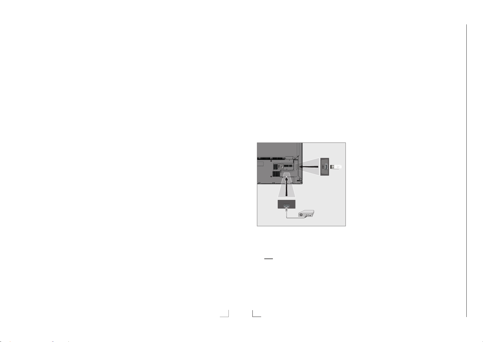
Externe Datenträger anschließen
Hinweise:
7
Vor dem Anschliessen des externen Datenträgers schalten Sie das Fernsehgerät mit
»
8« in Bereitschaft (Stand-by). Erst nach
dem Anschliessen schalten Sie das Fernsehgerät wieder ein.
7
Vor dem Entfernen des externen Datenträgers muss das Fernsehgerät grundsätzlich auf Stand-by geschaltet werden,
damit es nicht zu Datenverlusten kommt.
7
Ihr Fernsehgerät verfügt über zwei USBBuchsen, USB(HDD) und USB1.
USB(HDD) wird zum Anschluss von Da-
tentr
äger verwendet, die eine zusätzliche
Strom versorgung benötigen – beispielsweise externe Festplatten.
SERVICE
AV / S-VHS/COMPONENT
LAN
Optic Out USB(HDD)
HDMI3(ARC)
HDMI2
ANT-IN
SATELLITE
5V
13/18V
max. 50mA
max. 500mA
USB(HDD)
1 Buchse USB(HDD) des Fernsehgerätes und
entspr
echende Buchse des Datenträgers
(externe Festplatte) mit einem USB-Kabel
verbinden;
oder
USB-Stecker des USB-Memory Sticks in
Buchse USB1 des Fernsehgerätes stecken.
Hinweise:
7
Die Buchse USB1 des Fernsehgerätes
liefert gemäß USB-Spezifikationen maximal
500 mA Strom. Externe Festplatten, die
mehr Strom benötigen, dürfen daher nur an
die Buchse USB(HDD) des Fernseh gerätes
angeschlossen w
7
Wenn Sie für externe Festplatten, die an
erden.
die Buchse USB(HDD) des Fernsehgerätes
angeschlossenen wurden, ein Netzkabel
verwenden, muss dieses Netzkabel beim
Ab schalten des Fernsehgerätes ebenfalls
vom Stromnetz getrennt werden.
7
Externen Datenträger dürfen nicht vom
Fernsehgerät getrennt werden, während auf
Dateien des Datenträgers zugegriffen wird.
DEUTSCH
39
42
DEUTSCH
Page 15

USB-RECORDING
Chassis G5GRUNDIG Service
1 - 15
-------------------------------------------------------------------------------------------
USB-RECORDING
-------------------------------------------------------------------------------------------
Einstellungen für USB Recording
Menü anwählen
1 Menü mit »MENU« aufrufen.
V
2 Menüpunkt »Aufnahmen« mit »
»
« oder »>« wählen und mit »OK«
<
bestätigen.
– Das Menü »Medienplayer« wird ange-
zeigt.
V
3 Zeile »PVR« mit »
« or »Λ« wählen und
mit »OK« bestätigen.
4 Das Menü »Mediaoptionen« mit »TOOLS«
aktivier
en.
MedienPlayer > PVR
Channel_1_201548_154649.ts
Mediaoptionen
Anzeigemodus Auto
Auto-Vorschau Ein
Diaschauintervall 5
Datenträgerverwaltung
5 Die Zeile »Datenträgerverwaltung« mit »V«
oder »
Λ
« wählen und mit »OK« bestätigen.
Hinweis:
7
Die weitere Bedienung entnehmen Sie bitte
den folgenden Abschnitten.
Datenträger sicher entfernen
1 Im Menü »Datenträgerverwaltung« die Zeile
»Laufwerk sicher trennen« mit »
»
Λ
« wählen und mit »OK« bestätigen.
Hinweis:
7
Der Datenträger kann jetzt von der Buchse
abgezogen werden.
«, »Λ«,
Dienstag
xx xxx xxxx
V
« oder
Zurück
BACK
Externe Datenmedien auswählen
Wenn mehrere externe Datenträger an das
Fernsehgerät angeschlossen sind, können Sie
den gewünschten Datenträger auswählen.
1 Im Menü »Datenträgerverwaltung« die Zeile
V
»Datentr
äger« mit »
« oder »Λ« wählen
und mit »OK« bestätigen.
V
2 Gewünschten Datenträger mit »
»
Λ
« wählen.
« oder
3 Eine Menüebene zurückschalten mit »BACK
« oder Einstellung mit »EXIT« beenden.
<
Partition des externen Datenträgers
wählen
Wenn der externe Datenträger über mehrere
Partitionen verfügt, wählen Sie die gewünschte
aus.
1 Im Menü »Datenträgerverwaltung« die Zeile
V
»P
artition« mit »
« oder »Λ« wählen und
mit »OK« bestätigen.
V
2 Gewünschte Partition mit »
« oder »Λ«
wählen.
3 Eine Menüebene zurückschalten mit »BACK
« oder Einstellung mit »EXIT« beenden.
<
Externe Datenträger prüfen
Sie können externe Datenträger einer Prüfung
unterziehen und so herausfinden, ob sich diese
für die gewünschte Funktionalität eignen.
1 Im Menü »Datenträgerverwaltung« die Zeile
V
»Datentr
äger« mit »
« oder »Λ« wählen.
Wenn mehrere Datenträger angeschlossen
sind, den gewünschten Datenträger mit »
oder »
Λ
« wählen.
V
2 Zeile »Partition« mit »
« oder »Λ« wählen.
V
Wenn mehrere Partitionen vorhanden sind,
die gewünschte Partition mit »
V
« oder »Λ«
wählen.
V
3 Zeile »Datenträger prüfen« mit »
»
Λ
« wählen und mit »OK« bestätigen.
« oder
– Informationen zum Datenträger werden
angezeigt.
4 Eine Menüebene zurückschalten mit »BACK
« oder Einstellung mit »EXIT« beenden.
<
Partition des externen Datenträgers
formatieren
1 Im Menü »Datenträgerverwaltung« die Zeile
»Partition formatieren« mit »
V
« oder »Λ«
wählen und mit »OK« bestätigen.
2 Sicherheitsabfrage bestätigen, dazu mit »
oder »
« die Schaltfläche »Ja« anwählen
>
und mit »OK« bestätigen;
oder
Vorgang abbrechen, dazu mit »
»
« die Schaltfläche »Nein« anwählen und
>
mit »OK« bestätigen.
« oder
<
3 Eine Menüebene zurückschalten mit »BACK
« oder Einstellung mit »EXIT« beenden.
<
Timeshift – Sendungen
„anhalten″
Die aktuelle Sendung kann „angehalten” werden. Dies ist eine nützliche Funktion, wenn z.B.
während eines Spielfilmes das Telefon läutet,
und Sie die Fortsetzung des Films nicht verpas-
«
<
sen möchten.
Am Bildschirm erscheint ein Standbild der
letzten Szene, die Sendung wird im „Time ShiftSpeicher” des externen Datenträgers gespeichert
Im „Time Shift-Speicher” können Sie max. 60
Minuten der aktuellen Sendung aufnehmen.
Hinweis:
7
Verwenden Sie für störungsfreies „Permanent Timeshift“ eine externe USB-Festplatte.
1 Aktuelle Sendung mit »
!« anhalten.
– Das Bild wird eingefroren, der Zeitversatz
und die restliche Aufnahmezeit werden
angezeigt.
2 Sendung mit »
8« fortsetzen.
– Die Sendung wird weiterhin aufgezeich-
net.
Hinweis:
7
Die folgenden Funktionen sind während des
Timeshift-Betriebs möglich:
–
Zurückspulen, dazu »3« je nach Geschwindigkeit mehrmals drücken (das Bild
ist während des Rückspulens eingefroren);
–
Vorwärtsspulen, dazu »4« je nach Geschwindigkeit mehrmals drücken;
–
«
Pause mit »!« anwählen.
3 Timeshift-Funktion mit »
7« beenden.
– Die Meldung »Livesendung« wird einge-
blendet, Sie sehen die aktuelle Sendung
ohne Zeitversatz.
– Die Szenen im „Time Shift-Speicher” sind
gelöscht.
DEUTSCH
43
44
DEUTSCH
Page 16

Chassis G5GRUNDIG Service
1 - 16
USB-RECORDING
-------------------------------------------------------------------------------------------
Sendungen aufnehmen
Sie können Sendungen aufnehmen. Die Daten
dieser Sendungen werden auf einem externen
Datenträger gespeichert, die Verwaltung dieses
Archivs erfolgt durch das Fernsehgerät.
Für 1 Minute Aufnahme benötigen Sie – je nach
Fernsehprogramm – 44 MB bis 110 MB Speicherplatz auf dem externen Datenträger.
Während der Aufnahme können Sie vom Archiv
eine andere Sendung wiedergeben.
Ein Wechseln des Programmplatzes ist nur
bei Fernsehprogrammen möglich, die auf der
gleichen Frequenz (DVB-T/C) oder auf dem
gleichen Transponder (DVB-S) gesendet werden.
Wenn Sie während der Aufnahme auf eine
andere Programmquelle umschalten (mit Ausnahme von DVB-T, DVB-S, DVB-C oder USB)
wird die Aufnahme beendet.
Sofortaufnahme einer Sendung
1 Fernsehprogramm mit »1…0« oder »P+«,
»P–« wählen und Aufnahme mit »
starten.
– Informationen zur Aufnahme werden
eingeblendet: Das Aufnahmesymbol, der
Programmname, die Sendung, die Aufnahmezeit und der noch zur Verfügung
stehende Speicherplatz.
– Nach kurzer Zeit werden diese Informatio-
nen abgeschaltet.
2 Aufnahme mit »
3 Sicherheitsabfrage bestätigen, dazu mit »
oder »
und mit »OK« bestätigen;
oder
Vorgang abbrechen, dazu mit »
»
« die Schaltfläche »Nein« anwählen und
>
mit »OK« bestätigen.
Hinweise:
7
Nach Abschluss der Aufnahme wird die
Aufzeichnung automatisch auf dem externen Datenträger gespeichert.
7
Wird der externe Datenträger während der
Aufnahme von der USB-Buchse getrennt,
wird die Aufnahme automatisch abgebrochen und nicht gespeichert.
7« beenden.
« die Schaltfläche »Ja« anwählen
>
« oder
<
«
<
Aufnahme einer Sendung aus der Programmübersicht
1 Programmübersicht mit »OK« aufrufen.
2 Das gewünschte Fernsehprogramm mit »
oder »
« wählen und mit »OK« be stätigen.
>
3 Programmübersicht mit »EXIT« abschalten.
4 Aufnahme mit »
– Informationen zur Aufnahme werden
eingeblendet: Das Aufnahmesymbol, der
Programmname, die Sendung, die Aufnahmezeit und der noch zur Verfügung
stehende Speicherplatz.
– Nach kurzer Zeit werden diese Informatio-
nen abgeschaltet.
5 Aufnahme mit »
6 Sicherheitsabfrage bestätigen, dazu mit »
oder »
« die Schaltfläche »Ja« anwählen
>
und mit »OK« bestätigen;
oder
Vorgang abbrechen, dazu mit »
»
« die Schaltfläche »Nein« anwählen und
>
mit »OK« bestätigen.
«
« starten.
7« beenden.
« oder
<
SMART INTER@CTIVE TV 4.0 FUNKTIONEN
7
Smart Inter@ctive TV 4.0 Applikationen
Die Option „Smart Inter@ctive TV 4.0” Ihres
«
<
«
<
Fernsehgerätes bietet Ihnen den Zugang zum
Internet, wenn das Fernsehgerät an Ihrem Heimnetzwerk mit Internetzugang angeschlossen ist.
Sie können die verschiedensten Applikationen
aus dem Internet oder dem GRUNDIG AppLICATION store abrufen, Videos betrachten, Bilder ansehen und soziale Netzwerke besuchen.
Des Weiteren können Sie z. B. nach Sportmeldungen suchen, den Wetterbericht abrufen und
nach Ärzten und Apotheken suchen.
Hinweise:
7
Die Verfügbarkeit der Applikationen und ihr
Inhalt kann von Land zu Land unterschiedlich sein.
7
Mit „Smart Inter@ctive TV 4.0” können
keine Dateien heruntergeladen und gespeichert werden. Ein „Upload“ von Dateien
auf eine Web-Seite wird nicht unterstützt.
„Add-ons“ können nachträglich nicht instal-
liert werden, mit Ausnahme der Applikationen aus dem GRUNDIG AppLICATION
store.
7
Grundig ist nicht für den Inhalt und die
Qualität des Inhaltes der Applikationen
verantwortlich. Dies unterliegt der Verantwortung des jeweiligen Anbieters.
7
Lokale und Globale Applikationen unterliegen einem begrenzten Anwendungszeitraum durch die Diensteanbieter. Die
Diensteanbieter können Ihre Applikationen
uneingeschränkt ändern, einschränken,
erweitern und entfernen.
Grundig hat auf diese Änderungen keinen
Einfluss.
7
Grundig behält sich alle Rechte zum Ändern, Einschränken, Erweitern und Entfernen
der Internet Applikationen vor.
Bei verschiedenen Applikationen kann es
notwendig sein, über die Homepage der
Applikationen einen separaten Zugangscode anzufordern. Wenn Sie mit Ihrem
Fernsehgerät diese Homepage anwählen,
kann es sein, dass der Inhalt nicht durch das
Fernsehgerät unterstützt wird.
USB Tastatur und Maus
An beiden Buchsen USB(HDD) und an Buchse
USB1 kann eine USB-Tastatur mit Maus für die
Bedienung des W
werden.
Die Tastatur muss dem USB-Standard entsprechen. Eine Tastatur, die einen Treiber benötigt,
kann nicht verwendet werden.
ebBrowsers angeschlossen
Das Menü »SMART INTER@CTIVE
TV« anwählen
1 Menü mit »MENU« aufrufen.
2 Menüpunkt »Application Center« mit »
oder »
« wählen und mit »OK« bestätigen
<
oder das »Application Center« mit »@«
aufr
ufen.
– Das Anmeldemenü wird eingeblendet.
Hinweise:
7
Im „normalen“ Fernseh-Betrieb kann das
Menü »Meine Apps« mit »@« aufgerufen
und wieder abgeschaltet w
7
Wenn Sie eine Applikation starten und das
Fernsehgerät ist nicht mit dem Internet verbunden, wird eine Meldung eingeblendet.
Ist eine Internetverbindung eingerichtet,
jedoch keine »IP Adresse« vergeben, kann
die Applikation auch nicht angezeigt werden.
Überprüfen Sie in diesem Fall die Netz-
werkverbindung, siehe Kapitel auf den
Seiten 87 oder 90.
7
Das Navigieren in den Menüs und wie Sie
den Zugang zu den Applikationen einrichten, finden Sie in den nächsten Kapiteln.
-----------------------
«
>
erden.
DEUTSCH
45
DEUTSCH
57
Page 17
SMART INTER@CTIVE TV 4.0 FUNKTIONEN
Chassis G5GRUNDIG Service
1 - 17
-----------------------
SMART INTER@CTIVE TV 4.0 FUNKTIONEN
-----------------------
Navigieren und Texteingabe bei der
Anmeldung
1 Menü »Meine Apps« mit »@« aufrufen.
– Das Anmeldemenü wird eingeblendet.
Anmelden
Um Smart Apps vollständig nutzen zu können, müssen Sie sich
registrieren.
Angaben merken
Registrieren Anmelden
Überspringen
2 Registrierung mit »OK« starten.
V
3 Benötigtes Textfeld mit »
»
« wählen und mit »OK« bestätigen.
>
– Die virtuelle Tastatur wird eingeblendet.
«, »Λ«, »<« und
Hinweise zur Dateneingabe:
7
Benötigte Tastenbelegung (Sprache) der
Tastatur mit »yy« (grün) wählen.
7
Die Daten werden mit der virtuellen Tastatur
eingegeben. Den benötigten Buchstaben/
die Ziffer jeweils mit »
»
« wählen und mit »OK« bestätigen.
>
7
Zum Umschalten von Großbuchstaben auf
V
«, »Λ«, »<« und
Kleinbuchstaben die Schaltfläche »Shift«
ählen und mit »OK« bestätigen.
w
7
Mit »y« (rot) kann eine „Handytastatur“
eingeblendet werden.
7
Das letzte Zeichen/die letzte Ziffer kann mit
»
« (blau) gelöscht werden. Mit »
yyyy
(gelb) wir
7
Ist die Eingabe für die Zeile komplett, muss
d der gesamte Eintrag gelöscht.
sie „bestätigt“ werden, dazu mit »
»
« und »>« die Schaltfläche »<« wählen
<
und mit »OK« bestätigen.
Die Tastatur wird ausgeblendet.
V
«, »Λ«,
yyy
Zugang zu GRUNDIG AppLICATION
store einrichten
Wenn Sie die Function »GRUNDIG appLICATION store« zum ersten Mal benutzen, sollten
Sie einen persönlichen Zugang einrichten.
Durch diese Registrierung erhalten Sie vielfältige
Informationen zu den Grundig Applikationen.
1 Menü »Meine Apps« mit »@« aufrufen.
– Das Anmeldemenü wird eingeblendet.
2 Die Schaltfläche »Registrieren« mit »
»
Λ
«, »<« und »>« wählen und mit »OK«
bestätigen.
3 Name, Vorname, Telefonnummer (optional)
und Gebur
Buchstaben/Zahlen mit »
oder »
Nach der Eingabe mit »
»
>
mit »OK« bestätigen.
Zur nächsten Eingabe mit »
tsdatum eingeben:
« wählen und mit »OK« bestätigen.
>
V
V
«, »Λ«, »<« oder
« die Schaltfläche »< x« anwählen und
V
Tastatur mit »OK« einblenden.
Für weitere Eingaben mit »
oder »
« die Schaltfläche »Vorwärts«
>
anwählen und mit »OK« bestätigen.
V
Hinweis:
7
Die Schaltfläche »Rückwärts« wählen und
mit »OK« bestätigen um zur vorherigen
Eingabe zu gelangen.
4 Gerätename, E-Mailanschrift, Kennwort und
K
ennwortbestätigung eingeben:
Buchstaben/Zahlen mit »
oder »
Nach der Eingabe mit »
«
>
oder »
>
anwählen und mit »OK« bestätigen.
Zur nächsten Eingabe mit »
« wählen und mit »OK« bestätigen.
« die Schaltfläche »< Schließen«
V
V
«, »Λ«, »<«
V
Tastatur mit »OK« einblenden.
Für weitere Eingaben mit »
oder »
« die Schaltfläche »Vorwärts«
>
anwählen und mit »OK« bestätigen.
V
5 Ort eingeben:
Buchstaben/Zahlen mit »
oder »
« wählen und mit »OK« bestätigen.
Nach der Eingabe mit »
>
oder »
« die Schaltfläche »< Schließen«
>
anwählen und mit »OK« bestätigen.
V
V
«, »Λ«, »<«
V
«, »Λ«, »<«
« schalten und
«, »Λ«, »<«
«, »Λ«, »<«
« schalten und
«, »Λ«, »<«
«, »Λ«, »<«
6 Registrierung beenden, dazu mit »V«, »Λ«,
»
« oder »>« die Schaltfläche »Speichern«
<
anwählen und mit »OK« bestätigen.
– Die Registrierung ist beendet.
Applikationen auswählen
1 Menü »Meine Apps« mit »@« anwählen.
Meine Apps
Online Store
...
TV
Bei GRUNDIG AppLICATION store
anmelden
Wenn Sie das Fernsehgerät auf die Werkseinstellung zurückgesetzen und bei diesem Reset
«,
das „Häkchen“ im Feld »Installierte Anwendungen speichern« nicht gesetzt haben, werden
alle Applikationen die zuvor installiert wurden
wieder gelöscht.
Bei der Anwahl des Menüs »GRUNDIG appLICATION store« wird das „Anmeldemenü“ eingeblendet. Melden Sie sich bitte mit Ihrer E-Mail
Adresse und Ihrem Passwort wieder an.
1 Menü »Meine Apps« mit »@« aufrufen.
– Das Anmeldemenü wird eingeblendet.
2 E-Mail Adresse eingeben:
»OK« drücken, Daten eingeben, danach mit
V
«, »Λ«, »<« und »>« die Schaltfläche
»
»< Schließen« anwählen und mit »OK«
bes
tätigen.
V
3 Zur nächsten Eingabezeile mit »
« schalten
und Tastatur mit »OK« einblenden.
4 Kennwort eingeben:
V
Daten eingeben, danach mit »
»
« und »>« die Schaltfläche »< Schlie-
<
ßen« anwählen und mit »OK« bestätigen.
5 Die Schaltfläche »Anmelden« mit »
«, »Λ«,
V
«
Kategorien Werkzeuge Beenden
2 Gewünschte Applikation mit »V«, »Λ«,
»
« und »>« wählen und mit »OK« bestä-
<
tigen.
– Das Hauptmenü der gewählten Applikati-
on wird nach kurzer Zeit eingeblendet.
Hinweise:
7
Wird die Funktion »GRUNDIG appLICATION store« gewählt und das Fernsehgerät
hat keine Verbindung zum Internet, wird ein
Hinweis eingeblendet.
7
Besteht eine Netzwerkverbindung über
LAN oder WLAN, es wird jedoch keine
IP-Adresse empfangen oder die Internetverbindung wird nicht hergestellt, kann die
Funktion »GRUNDIG appLICATION store«
nicht gestartet weren. Bitte die Netzwerkanschlüsse überprüfen, siehe Seite 87 oder 90
anwählen und mit »OK« bestätigen.
– Die Anmeldung startet, nach kurzer Zeit
werden Applikationen angezeigt.
6 Gewünschte Applikation zur Synchronisie-
V
ung mit »
r
«, »Λ«, »<« und »>« anwählen
und mit »OK« bestätigen.
Die Schaltfläche »Synchronisieren« mit »
V
«
anwählen und mit »OK« bestätigen.
– Die Applikation wird angezeigt.
7 Nach dem Download der Applikation
»OK« drücken.
– Das Menü »Grundig Meine Apps« wird
angezeigt.
58
DEUTSCH
DEUTSCH
59
Page 18

SMART INTER@CTIVE TV 4.0 FUNKTIONEN
Chassis G5GRUNDIG Service
1 - 18
-----------------------
SMART INTER@CTIVE TV 4.0 FUNKTIONEN
-----------------------
Der GRUNDIG Online Store
Im GRUNDIG Online Store, der Ihnen Online
angeboten wird, finden Sie zahlreiche Applikationen, die Sie auf Ihrem Fernsehgerät installieren
können.
Im Menü »GRUNDIG appLICATION Store«
sind ab Werk einige Applikationen installiert.
Im GRUNDIG Online Store finden Sie eine
große Auswahl weiterer Applikationen, die Sie
herunterladen können.
1 Menü »Meine Apps« mit »@« anwählen.
2 Den Grundig Online Store anwählen, dazu
die Schaltf
»
Λ
bestätigen.
– Der »GRUNDIG appLICATION Store«
läche »Online Store« mit »
«, »<« und »>« wählen und mit »OK«
wird eingeblendet.
V
«,
Applikationen herunterladen und installieren
1 Im Menü »GRUNDIG appLICATION Store«
die gewünschte Kategorie der Applikationen mit »
V
zu den Applikationen schalten;
oder
gewünschte Applikation nach Kriterien
wählen:
»Sehr beliebt«,
»Höchst bewertet«,
»Veröffentlichungsdatum«;
oder
wenn gezielt nach einer Applikation gesucht
werden soll, mit »
die Schaltfläche „Suche“ anwählen, mit
»OK« bestätigen, und Suchbegriff über die
vir
2 Gewünschte Applikation mit »
»
<
tigen.
– Informationen zur Applikation werden
eingeblendet.
3 Download starten, dazu die Schaltfläche
»Ins
die Schaltf
tigen.
– Die Applikation wird heruntergeladen und
installiert.
4 Die Applikation mit »OK« starten;
oder
zum Download weiterer Applikationen »@«
drücken.
« oder »Λ« wählen und mit »>«
V
«, »Λ«, »<« und »>«
tuelle Tastatur eingeben.
V
« und »>« wählen und mit »OK« bestä-
tallieren« mit »OK« bestätigen, danach
läche »Starten« mit »OK« bestä-
«, »Λ«,
Applikationen deinstallieren
1 Applikation, die deinstalliert werden soll mit
»
V
«, »Λ«, »<« und »>« wählen.
2 Das Menü »Werkzeuge« mit »yy« (grün) ak-
tivier
en, die Option »Deinstallieren« mit »
oder »
« wählen und mit »OK« bestätigen.
– Ein Sicherheitshinweis wird eingeblendet.
3 Schaltfläche »Deinstallieren« mit »OK«
oder
mit »
4 Vorgang mit »OK« beenden.
Applikationen bewerten
Sie können die Applikationen im Menü »GRUNDIG appLICATION store« bewerten.
1 Im Menü »Meine Apps« die Übersicht der
2 Applikation, die bewertet werden soll mit
3 Das Menü »Werkzeuge« mit »yy« (grün)
4 Einmal »
Mit »
5 Vorgang mit »OK« beenden.
>
bes
tätigen;
« oder »>« die Schaltfläche »Abbre-
<
chen wählen« und mit »OK« bestätigen.
K
ategorien mit »y« (rot) aufrufen und die
ge
wünschte Kategorie mit »
wählen.
V
«, »Λ«, »<« und »>« wählen.
»
aktivier
en, die Option »Bewertung« mit »
oder »
« wählen und mit »OK« bestätigen.
>
Λ
»
<
wählen mit »OK« bestätigen.
« drücken und Bewertung mit
« oder »>« eingeben.
V
« die Schaltfläche »Bewertung«
« oder »>«
<
<
<
Applikationen als Favoriten markieren
Sie können bevorzugte Applikationen als Favoriten markieren. Diese finden Sie schnell in der
Kategorie „Favoriten“.
«
1 Im Menü »Meine Apps« die Übersicht der
K
ategorien mit »y« (rot) aufrufen und die
ge
wünschte Kategorie mit »
wählen.
2 Applikation, die markiert werden soll mit
V
«, »Λ«, »<« und »>« wählen.
»
3 Das Menü »Werkzeuge« mit »yy« (grün))
aktivier
en, die Option »FAV setzen« mit »
oder »
« wählen und mit »OK« bestätigen.
– Die Applikation wird mit »★« markiert und
«
>
zur K
ategorie „Favoriten“ kopiert.
« oder »>«
<
«
<
60
DEUTSCH
DEUTSCH
61
Page 19
SMART INTER@CTIVE TV 4.0 FUNKTIONEN
Chassis G5GRUNDIG Service
1 - 19
-----------------------
JUGENDSCHUTZEINSTELLUNGEN
-------------------------------------------
Hauptmenü
1 Die Applikationen.
2 Schaltfläche zum
Online S
tore.
3 Suchleiste.
4 Wählt die Kategorien.
5 Wählt weitere Funkti-
onen.
6 Beendet die Funktion.
Meine Apps
Navigation im Hauptmenü
1 Mit »y« (rot) die Übersicht der Kategorien
einblenden. Gewünschte Kategorie mit »
oder »
« wählen.
>
2 Gewünschte Applikation mit »
»
« und »>« wählen und mit »OK« bestä-
<
tigen.
V
<
«, »Λ«,
– Das Hauptmenü der gewählten Applikati-
on wird nach kurzer Zeit eingeblendet.
3 Die weitere Bedienung und mögliche An-
endungen sind abhängig von der Struktur
w
in den Untermenüs der jeweiligen Applikation. Beachten Sie auch die Hinweise in den
Menüs.
Wiedergabe und Zusatzfunktionen beim Abspielen der Applikationen
Hinweis:
7
Einige Applikationen unterstützen nicht alle
Wiedergabe-Funktionen, die Anwahl der
Wiedergabe-Funktionen kann voneinander
abweichen.
1 Wiedergabe mit »
2 Wiedergabe-Pause mit »
3 Wiedergabe mit »
8« starten.
!« wählen.
7« beenden.
Online Store
2
1
Kategorien Werkzeuge Beenden
4 5 6
3
4 Während der Wiedergabe Bildsuchlauf mit
»
3
« und »4« wählen.
5 Während der Wiedergabe das vorherige/
«
nächs
te Thema mit »
5« oder »6« wählen.
6 Bildinhalt anwählen oder Schreibmarke
(Cursor) in der vir
»
Λ
«, »<« und »>« verschieben.
tuellen Tastatur mit »
7 Anwahl/Eingabe in den Applikationen oder
in der vir
tuellen Tastatur mit »OK« bestäti-
gen.
8 Verschiedene Untermenüs und Funktionen in
den Applik
»y« (rot), »yy« (grün), »
»
yyyy
ationen können mit »1…0«,
« (gelb) und
yyy
« (blau) gewählt werden.
9 Die jeweilige Applikation mit »@« abschal-
ten.
10 Die Funktion „SMART Inter@ctive TV 4.0”
mit »EXIT« abschalten.
1 Menü mit »MENU« aufrufen.
V
2 Menüpunkt »Einstellungen« mit »
»
Λ
«, »<« oder »>« wählen und mit »OK«
«,
bestätigen.
3 Die Option »Jugendschutz« mit »
»
« wählen und mit »V« bestätigen.
<
– Das Menü »Jugendschutz« ist aktiv
Einstellungen > Jugendschutz
Bild
Jugendschutz Aus
Menü sperren Aus
Tastensperre Aus
PIN ändern
Wählen Modus ändern BeendenZurück
Quelle TimerlisteTon NetzwerkTV Jugendschutz
« oder
>
Dienstag
xx xxx xxxx
BACK EXIT
Hinweis:
7
Die weitere Bedienung entnehmen Sie bitte
den folgenden Abschnitten.
Sendungen autorisieren
V
«,
Es gibt Spielfilme, deren Inhalt oder auch
Szenen nicht für Kinder geeignet sind.
Diese Sendungen enthalten Informationen, die
den Inhalt oder die Szenen markieren und sind
mit Zugangslevel von 4 bis 18 versehen. Sie
können einen der Zugangslevel wählen und damit die Wiedergabe autorisieren.
1 Im Menü »Jugendschutz« die Zeile »Jugend-
V
schutz« mit »
»
« oder »>« bestätigen.
<
« oder »Λ« wählen und mit
Menüs sperren
Mit dieser Funktion können Sie folgende Menüs des Fernsehgerätes sperren: »Automatischer
Suchlauf«, »Manuelle Abstimmung« und »Programmtabelle«. Diese Menüs sind nur durch Eingabe des PIN-Codes zugänglich.
1 Im Menü »Jugendschutz« die Zeile »Menü
sper
ren« mit »
»
« oder »>« bestätigen.
<
V
« oder »Λ« wählen und mit
2 PIN-Code »1234« mit »1...0« eingeben.
3 Sperre mit »
« oder »>« aktivieren (»Ein«).
<
Hinweis:
7
Menüsperre abschalten dazu mit »<« oder
»
« die Einstellung »Aus« wählen.
>
4 Eine Menüebene zurückschalten mit »BACK
« oder Einstellung mit »EXIT« beenden.
<
Multifunktionsschalter sperren
Bei aktiver Tastensperre ist der Mulifunktionsschalter am Fernsehgerät ohne Funktion.
1 Im Menü »Jugendschutz« die Zeile »Tasten-
sper
»
« oder »>« bestätigen.
<
2 PIN-Code »1234« mit »1...0« eingeben.
3 Tastensperre mit »
(Ein) oder abschalten (Aus).
4 Eine Menüebene zurückschalten mit »BACK
<
V
re« mit »
« oder »Λ« wählen und mit
« oder »>« aktivieren
<
« oder Einstellung mit »EXIT« beenden.
2 PIN-Code »1234« mit »1...0« eingeben.
3 Zugangslevel mit »
« oder »>« wählen.
<
4 Eine Menüebene zurückschalten mit »BACK
« oder Einstellung mit »EXIT« beenden.
<
Hinweis:
7
Bei der Wiedergabe einer Time-Shift Aufnahme kann es vorkommen, dass ein Zugangslevel eingegeben werden muss. Der
Grund hierfür ist, die aktuell aufgezeichnete
Sendung im Time-Shift Speicher ist “jugendgeschützt”.
62
DEUTSCH
70
DEUTSCH
Page 20

JUGENDSCHUTZEINSTELLUNGEN
Chassis G5GRUNDIG Service
1 - 20
-------------------------------------------
JUGENDSCHUTZEINSTELLUNGEN
-------------------------------------------
PIN-Code ändern
Sie können statt des Werkscodes »1234« einen
persönlichen PIN-Code eingeben. Notieren Sie
sich bitte Ihren persönlichen PIN-Code.
1 Im Menü »Jugendschutz« die Zeile »PIN
änder
»OK« bestätigen.
2 Aktuellen PIN-Code 1 2 3 4 mit »1...0«
eingeben.
3 Persönlichen neuen PIN-Code mit »1...0«
viers
4 Persönlichen neuen PIN-Code mit »1...0«
noch einmal eingeben.
5 Eine Menüebene zurückschalten mit »BACK
« oder Einstellung mit »EXIT« beenden.
<
V
n« mit »
tellig eingeben.
« oder »Λ« wählen und mit
Fernsehprogramme sperren
Sie können einzelne Fernsehprogramme mit
einem persönlichen PIN-Code sperren, zum
Beispiel Programme, die sich nicht für Kinder
eignen.
1 Menü mit »MENU« aufrufen.
V
« oder »<«
>
yyy
« markiert.
«, »Λ«,
V
« oder
V
«, »Λ«,
« (gelb)
V
« oder
yyy
2 Menüpunkt »Einstellungen« mit »
»
« oder »>« wählen und mit »OK« bestä-
<
tigen.
3 Die Option »Quelle« mit »
wählen und mit »
4 Die Zeile »Programmtabelle« mit »
»
Λ
« wählen und mit »OK« bestätigen.
5 Das zu sperrende Programm mit »
»
« oder »>« markieren.
<
– Das Programm wird mit »« markiert.
6 Den Bearbeitungsmodus mit »
aktivier
en.
7 Die Zeile »Programmsperre« mit »
»
Λ
« wählen und mit »OK« bestätigen.
8 PIN-Code »1234« mit »1 ... 0« eingeben.
9 Funktion mit »OK« bestätigen.
– Das Programm wird mit »
Hinweis:
7
Zum Aufheben der Sperre das Programm
mit »
V
wählen, den Bearbeitungsmodus mit »
(gelb) aktivier
geben« mit »
»OK« bestätigen.
10 Einstellung mit »EXIT« beenden.
V
« bestätigen.
«, »Λ«, »<« oder »>« wieder an-
en, die Zeile »Programm frei-
V
« oder »Λ« wählen und mit
Ein gesperrtes Fernsehprogramm ansehen
Sie können ein durch den PIN-Code gesperrtes
Fernsehprogramm freigeben.
1 Das gesperrte Fernsehprogramm mit
»1…0« oder »P+«, »P–« anwählen.
2 PIN-Code »1234« mit »1 ... 0« eingeben.
Hinweis:
7
Das Fernsehprogramm wird nach einem
Wechsel des Programmplatzes wieder
gesperrt.
PIN-Code zurückstellen
Diese Funktion benutzen Sie, wenn Sie den PINCode vergessen haben.
1 Im Menü »Jugendschutz« die Zeile »PIN
änder
»OK« bestätigen.
2 PIN-Code 2 3 5 6 mit »1...0« eingeben.
3 Persönlichen neuen PIN-Code mit »1...0«
viers
4 Persönlichen neuen PIN-Code mit »1...0«
noch einmal eingeben.
5 Eine Menüebene zurückschalten mit »BACK
« oder Einstellung mit »EXIT« beenden.
<
«
V
n« mit »
tellig eingeben.
« oder »Λ« wählen und mit
DEUTSCH
71
72
DEUTSCH
Page 21

GERÄTESOFTWARE
Chassis G5GRUNDIG Service
1 - 21
--------------------------------------------------------------------------------------
ZUBEHÖR VERWALTEN
--------------------------------------------------------------------------
1 Menü mit »MENU« aufrufen.
V
2 Menüpunkt »Einstellungen« mit »
»
« oder »>« wählen und mit »OK« bestä-
<
tigen.
3 Die Option »TV« mit »
und mit »
V
« bestätigen.
« oder »<« wählen
>
«, »Λ«,
– Das Menü »TV« ist aktiv.
V
4 Die Zeile »Info« mit »
« oder »Λ« wählen
und mit »OK« aktivieren.
Einstellungen > TV > Info
Bild
Produktinfo
TV Name Smart Inter@ctive 4...
Softwareaktualisierungen
Werkseinstellungen
Kanalverlauf rücksetzen
Land Dutchland
Wählen Bestätigen BeendenZurück
Quelle TimerlisteTon NetzwerkTV Jugendschutz
Dienstag
xx xxx xxxx
BACK EXIT
Hinweis:
7
Die weitere Bedienung entnehmen Sie bitte
den folgenden Abschnitten.
Softwareversion abrufen
1 Im Menü »Info« die Zeile »Produktinfo«
mit »
V
« oder »Λ« wählen und mit »OK«
bestätigen.
– Die Softwareversion des Gerätes wird
eingeblendet.
2 Eine Menüebene zurückschalten mit »BACK
« oder Einstellung mit »EXIT« beenden.
<
Software aktualisieren (OAD)
(über Satellit, nur bei digitalen Programmen)
1 Im Menü »Info« die Zeile »Softwareaktuali-
ungen« mit »
sier
mit »OK« bestätigen.
2 Die Option »OAD« mit »
len und mit »OK« bestätigen.
– Die neue Software wird gesucht.
Hinweis:
7
Ist keine neue Software vorhanden, wird
das Menü automatisch abgeschaltet.
3 Ist eine neue Software vorhanden, die Soft-
are mit »yy« (grün) installieren.
w
– Die neue Software wird geladen.
74
DEUTSCH
V
« oder »Λ« wählen und
V
« oder »Λ« wäh-
Achtung:
7
Während des Updates das Fernsehgerät
nicht ausschalten! Nach erfolgreichen Update schaltet sich das Fernsehgerät automatisch aus und wieder ein.
Hinweis:
7
Wenn automatisch nach Softwareaktuali-
sierungen gesucht werden soll, im Menü
»Quelle« ° »Erweitert« die Zeile »OAD«
mit »
V
« oder »Λ« wählen und mit »<«
oder »
« die Option »Ein« wählen.
>
Software aktualisieren
(Internet)
(über Internet, nur bei digitalen Programmen)
1 Im Menü »Info« die Zeile »Softwareaktuali-
V
sier
ungen« mit »
« oder »Λ« wählen und
mit »OK« bestätigen.
V
2 Die Option »Internet« mit »
« oder »Λ«
wählen und mit »OK« bestätigen.
– Die neue Software wird gesucht.
Hinweis:
7
Ist keine neue Software vorhanden, wird
das Menü automatisch abgeschaltet.
3 Ist eine neue Software vorhanden, die Soft-
w
are mit »yy« (grün) installieren.
– Die neue Software wird geladen.
Achtung:
7
Während des Updates das Fernsehgerät
nicht ausschalten! Nach erfolgreichen Update schaltet sich das Fernsehgerät automatisch aus und wieder ein.
Software aktualisieren (USB)
1 USB-Stecker des USB-Memory Sticks in
eine der Buchsen USB des Fernsehgerätes
s
tecken.
2 Im Menü »Info« die Zeile »Softwareaktuali-
sier
ungen« mit »
mit »OK« bestätigen.
3 Die Option »USB« mit »
len und mit »OK« bestätigen.
– Die Software vom USB-Memory Stick
wird installiert.
V
« oder »Λ« wählen und
V
« oder »Λ« wäh-
Sie können an Ihr Fernsehgerät umfangreiches
Zubehör anschließen. Im folgend beschriebenen
Menü sehen Sie den Status des jeweiligen Gerätes und können dafür Einstellungen vornehmen.
1 Menü mit »MENU« aufrufen.
V
2 Menüpunkt »Einstellungen« mit »
»
« oder »>« wählen und mit »OK« bestä-
<
tigen.
3 Die Option »TV« mit »
und mit »
V
« bestätigen.
« oder »<« wählen
>
«, »Λ«,
– Das Menü »TV« ist aktiv.
V
4 Die Zeile »Zubehör« mit »
« oder »Λ«
wählen und mit »OK« bestätigen.
V
5 Die benötigte Zeile mit »
« oder »Λ«
wählen und mit »OK« bestätigen.
Die gewünschte Funktion mit »
wählen.
« oder »<«
>
6 Eine Menüebene zurückschalten mit »BACK
« oder Einstellung mit »EXIT« beenden.
<
Hinweise:
7
Das Zubehör ist nicht im Lieferumfang des
Fernsehgerätes enthalten. Fragen Sie bitte
Ihren Fachhändler.
7
Die Anzeige des Status und die Einstel-
lungen sind abhängig vom verwendeten
Zubehör.
DEUTSCH
75
Page 22
RESET-FUNKTIONEN
Chassis G5GRUNDIG Service
1 - 22
----------------------------------------------------------------------------------
NETZWERK INSTALLATION
------------------------------------------------------------------
1 Menü mit »MENU« aufrufen.
V
2 Menüpunkt »Einstellungen« mit »
»
« oder »>« wählen und mit »OK« bestä-
<
tigen.
3 Die Option »TV« mit »
und mit »
V
« bestätigen.
« oder »<« wählen
>
«, »Λ«,
– Das Menü »TV« ist aktiv.
V
4 Die Zeile »Info« mit »
« oder »Λ« wählen
und mit »OK« aktivieren.
Einstellungen > TV > Info
Bild
Produktinfo
TV Name Smart Inter@ctive 4...
Softwareaktualisierungen
Werksinstellungen
Kanalverlauf rücksetzen
Land Deutschland
Wählen Bestätigen BeendenZurück
Quelle TimerlisteTon NetzwerkTV Jugendschutz
Dienstag
xx xxx xxxx
BACK EXIT
Hinweis:
7
Die weitere Bedienung entnehmen Sie bitte
den folgenden Abschnitten.
Fernsehgerät auf die Werkseinstellungen zurücksetzen
Mit dieser Funktion löschen Sie die Programmtabellen und alle persönlichen Einstellungen.
1 Im Menü »Info« die Zeile »Werkseinstellun-
gen« mit »
»OK« bestätigen.
– Eine Warnung wird eingeblendet.
Hinweis:
7
Wenn die geladenen Applikationen auch
gelöscht werden sollen, die Zeile »Installierte Anwendungen speichern« mit »
len und mit »OK« das Häkchen entfernen.
2 Sicherheitsabfrage bestätigen, dazu mit »
oder »
und mit »OK« bestätigen;
oder
Vorgang abbrechen, dazu mit »
»
mit »OK« bestätigen.
– Das Menü »TV« wird kurz ein geblendet.
V
« oder »Λ« wählen und mit
Λ
« wäh-
« die Schaltfläche »Ja« anwählen
>
« oder
« die Schaltfläche »Nein« anwählen und
>
<
3 Einstellungen mit Kapitel „Erstinstallation und
Fernsehprogramme einstellen“ auf Seite 19
fortsetzen.
Kanalverlauf zurücksetzen
Mit dieser Funktion löschen Sie die zuletzt gesehenen Programme im Hauptmenü.
1 Im Menü »Info« die Zeile »Kanalverlauf
setzen« mit »
rück
mit »OK« bestätigen.
– Eine Warnung wird eingeblendet.
2 Sicherheitsabfrage bestätigen, dazu mit »
oder »
>
und mit »OK« bestätigen;
oder
Vorgang abbrechen, dazu mit »
»
« die Schaltfläche »Nein« anwählen und
>
mit »OK« bestätigen.
– Die zuletzt gesehenen Programme im
Hauptmenü sind gelöscht.
3 Eine Menüebene zurückschalten mit »BACK
« oder Einstellung mit »EXIT« beenden.
<
«
<
V
« oder »Λ« wählen und
« die Schaltfläche »Ja« anwählen
« oder
<
V
Anmeldung am Router für den
LAN-Betrieb
Sie haben zwei Möglichkeiten, Ihr Fernsehgerät
am Heimnetzwerk anzumelden.
A Die automatische Anmeldung,
dabei werden alle notwendigen Einstellungen (»IP Adresse«, »DNS«, »Netzmaske«
und »Gateway«) vom Router automatisch
vergeben.
B Die manuelle Anmeldung,
hier müssen alle notwendigen Einstellungen
«
<
(»IP Adresse«, »DNS«, »Netzmaske« und
»Gateway«) von Hand eingegeben werden.
Automatische Anmeldung
Die meisten Heimnetze sind dynamisch. Wenn
Sie ein dynamisches Netzwerk verwenden,
benötigen Sie einen DSL Router, der DHCP
unterstützt.
Bei dynamischen Heimnetzen werden die Daten
für IP Adresse, Netzwerkmaske und Gateway
5 Die Option »Kabel« mit »
len und mit »OK« bestätigen.
6 Zeile »Netzwerkkonfiguration« mit »
oder »
Λ
« wählen und die Option »Auto«
mit »
« oder »>« wählen.
<
7 Anmeldung an das Heimnetzwerk mit »y«
(r
ot) starten.
– Die Meldung »Verbinde... Bitte warten«
wird eingeblendet.
8 Wenn die Meldung erlischt, mit »yy« (grün)
erbindung zum Netzwerk prüfen.
die V
– Anzeige: »Testen ... Bitte warten«, nach
erfolgreicher Anmeldung: »Verbindung mit
Gateway: Erfolgreich« und »Internetverbindung: Erfolgreich«.
9 Einstellung mit »EXIT« beenden.
Hinweis:
7
Wenn die IP Adresse nicht automatisch
vergeben wird, setzen Sie die Einstellung im
Kapitel „Manuelle Anmeldung“ fort.
« or »Λ« wäh-
V
«
vom Router automatisch zugewiesen. Manuelle
Einstellungen sind nicht notwendig.
1 Menü mit »MENU« aufrufen.
V
2 Menüpunkt »Einstellungen« mit »
»
« oder »>« wählen und mit »OK« bestä-
<
tigen.
3 Die Option »Netzwerk« mit »
wählen und mit »
V
« bestätigen.
«, »Λ«,
« oder »<«
>
– Das Menü »Netzwerk« ist aktiv.
Einstellungen > Netzwerk
Bild
Verbindungstyp ändern Kabel
Netzwerkkonfiguration Auto
Wake-on-LAN Aus
Erweitert Aus
Quelle TimerlisteTon NetzwerkTV Jugendschutz
WählenVerbinden Testen Bestätigen Zurück
xx xxx xxxx
Dienstag
BACK
4 Zeile »Verbindungstyp ändern« mit »V«
oder »
Λ
« wählen und mit »OK« bestäti-
gen.
76
DEUTSCH
88
DEUTSCH
Page 23
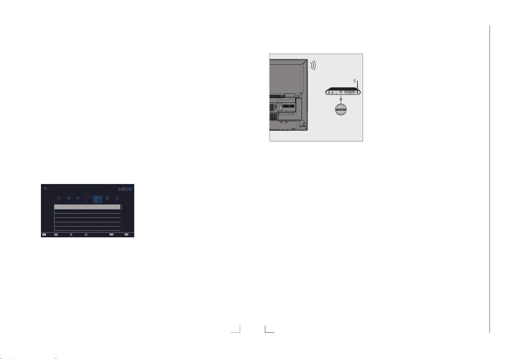
Chassis G5GRUNDIG Service
1 - 23
NETZWERK INSTALLATION
Manuelle Anmeldung
Wenn keine automatische IP-Adresse vorhanden
ist, müssen Sie die Zugangsdaten für »IP Adresse«, »DNS«, »Netzmaske« und »Gateway« von
Hand eingeben. Diese Zugangsdaten erhalten
Sie vom Administrator Ihres Netzwerkes.
1 Menü mit »MENU« aufrufen.
V
« oder »<«
>
V
« oder »Λ«
xx xxx xxxx
« wählen.
« wählen.
«, »Λ«,
V
V
Dienstag
«
«
BeendenErw. Einst. schl.
EXITBACK
2 Menüpunkt »Einstellungen« mit »
»
« oder »>« wählen und mit »OK« bestä-
<
tigen.
3 Die Option »Netzwerk« mit »
wählen und mit »
V
« bestätigen.
– Das Menü »Netzwerk« ist aktiv.
4 Zeile »Verbindungstyp ändern« mit »
oder »
Λ
« wählen und mit »OK« bestätigen.
5 Die Option »Kabel« mit »
wählen und mit »OK« bestätigen.
6 Zeile »Netzwerkkonfiguration« mit »
oder »
Λ
« wählen und die Option »Manu-
ell« mit »
– Die Eingaben für »IP Adresse«, »DNS«,
« oder »>« wählen.
<
»Netzmaske« und »Gateway« sind aktiv.
Einstellungen > Netzwerk
Bild
Verbindungstyp ändern Kabel
Netzwerkkonfiguration Manuell
Wake-on-LAN Aus
IP Adresse 192 . 168 . 000 . 200
DNS 192 . 168 . 000 . 254
Netzmaske 255 . 255 . 255 . 200
Quelle TimerlisteTon NetzwerkTV Jugendschutz
Eingabemodus
WählenVerbinden Testen
7 Zeile »IP Adresse« mit »V« wählen.
IP Adresse mit »1…0« eingeben.
V
8 Zeile »DNS« mit »
« wählen.
DNS mit »1…0« eingeben.
9 Zeile »Netzmaske« mit »
V
Netzmaske mit »1…0« eingeben.
10 Zeile »Gateway« mit »
V
Gateway mit »1…0« eingeben.
------------------------------------------------------------------
11 Anmeldung an das Heimnetzwerk mit »y«
(r
ot) starten.
– Die Meldung »Verbinde... Bitte warten«
wird eingeblendet.
12 Wenn die Meldung erlischt, mit »yy« (grün)
erbindung zum Netzwerk prüfen.
die V
– Anzeige: »Testen ... Bitte warten«, nach
erfolgreicher Anmeldung »Verbindung mit
Gateway: Erfolgreich« und »Internetverbindung: Erfolgreich«.
13 Einstellung mit »EXIT« beenden.
NETZWERK INSTALLATION
Betrieb über WLAN
SERVICE
AV / S-VHS/COMPONENT
LAN
Optic Out USB(HDD)
HDMI3(ARC) HDMI2
SATELLITE
ANT-IN
13/18V
5V
max. 500mA
max. 50mA
1 Das Gerät ist mit einem eingebautem
WLAN Modul für die Verbindung zum
Heimnetzwerk ausgestattet.
Hinweise:
7
Das WLAN Modul unterstützt das Datenübertragungsprotokoll nach IEEE
802.11B/G und N.
Um Videostörungen zu vermeiden, empfeh-
len wir – wenn vom Router unterstützt – den
Standard IEEE 802.11N zu verwenden.
Die beste Bildqualität bei HD Videowieder-
gabe erhalten Sie nur über eine LANVerbindung.
7
Wenn Sie einen Router verwenden, der
den Standard IEEE 802.11B/G unterstützt,
kann die Qualität der Videowiedergabe,
verglichen zum Standard IEEE 802.11N,
geringer sein. Die Ursache ist die geringere Datentransferrate des Standards IEEE
802.11B/G.
7
Die Wiedergabequalität beim Betrieb mit
einer DLNA-Applikation und mit der SMART
inter@ctive TV 4.0 Funktion ist davon abhängig, wieviele Benutzer das kabellose
Heimnetz gleichzeitig nutzen.
------------------------------------------------------------------
7
Wir empfehlen, während des Betriebes mit
der SMART Inter@ctive TV 4.0 Funktion
andere Geräte im Heimnetzwerk abzuschalten, um unnötigen Datenverkehr zu
vermeiden.
7
Stellen Sie den Router an einer erhöhten
Position auf, um die Empfangsqualität des
WLAN Moduls zu verbessern.
7
Die Empfangsqualität beim drahtlosen
Betrieb ist abhängig vom Router und dem
Abstand zwischen Router und Fernsehgerät
sowie dem Digitalen Media Server (DMS).
Anmeldung am Router für den
WLAN-Betrieb
Sie haben verschiedene Möglichkeiten, Ihr Fernsehgerät am Heimnetzwerk anzumelden.
A Die automatische Anmeldung,
dabei werden alle notwendigen Einstellungen (»IP Adresse«, »DNS«, »Netzmaske«
und »Gateway«) vom Router automatisch
vergeben.
Abhängig vom Router verwenden Sie:
– die Option „WPS-PBC“ (Push Button Con-
figuration);
– die Anmeldung mittels WPS-PIN;
– die Anmeldung mit Eingabe des Netz-
werk-Kennwortes.
B Die manuelle Anmeldung,
hier müssen alle notwendigen Einstellungen
(»IP Adresse«, »DNS«, »Netzmaske« und
»Gateway«) von Hand eingegeben werden.
DEUTSCH
89
90
DEUTSCH
Page 24
NETZWERK INSTALLATION
Chassis J5GRUNDIG Service
1 - 24
Chassis G5GRUNDIG Service
1 - 24
------------------------------------------------------------------
NETZWERK INSTALLATION
------------------------------------------------------------------
Voraussetzungen
Die meisten Heimnetze sind dynamisch, d.h.
die Daten für IP Adresse, Netzwerkmaske und
Gateway werden vom Router automatisch zugewiesen.
Wenn Sie ein dynamisches Netzwerk verwenden, benötigen Sie einen DSL Router, der DHCP
unterstützt.
Automatische Anmeldung mit „WPSPBC“ (Push Button Configuration)
Verwenden Sie diese Art der Anmeldung,
wenn Ihr Router „WPS-PBC“ unterstützt. Alle
Sicherheitseinstellungen werden automatisch
übernommen.
1 Menü mit »MENU« aufrufen.
V
2 Menüpunkt »Einstellungen« mit »
»
« oder »>« wählen und mit »OK« bestä-
<
tigen.
3 Die Option »Netzwerk« mit »
wählen und mit »
V
« bestätigen.
«, »Λ«,
« oder »<«
>
– Das Menü »Netzwerk« ist aktiv.
V
4 Zeile »Verbindungstyp ändern« mit »
oder »
Λ
« wählen und mit »OK« bestätigen.
5 Die Option »Kabellos WPS« mit »
»
« wählen und mit »OK« bestätigen.
>
– Eine Abfrage wird eingeblendet.
6 Sicherheitsabfrage bestätigen, dazu mit »
oder »
« die Schaltfläche »Ja« anwählen
>
und mit »OK« bestätigen.
V
7 Zeile »WPS-Typ« mit »
und die Option »Taste« mit »
wählen.
Einstellungen > Netzwerk
Bild
Verbindungstyp ändern Kabellos WPS
WLAN Ein
WPS-Typ Taste
Netzwerk wählen N/A
Netzwerkkonfiguration Auto
Wake-on-LAN Aus
Verbinden Testen BeendenZurück
Quelle TimerlisteTon NetzwerkTV Jugendschutz
Wählen
« oder »Λ« wählen
<
Modus ändern
«
« oder
<
« oder »>«
Dienstag
xx xxx xxxx
<
EXITBACK
8 Anmeldung an das Heimnetzwerk mit »y«
(rot) starten.
– Die Meldung »WPS-Taste an ...« wird
eingeblendet.
9 Am Router die WPS-Taste drücken.
10 Die Schaltfläche »Weiter« mit »
wählen und mit »OK« bestätigen.
– Die Meldung »Verbindung mit Gateway:
Erfolgreich« wird eingeblendet.
11 Wenn die Meldung erlischt, mit »yy« (grün)
die V
erbindung zum Netzwerk prüfen.
– Anzeige: »Testen ... Bitte warten«, nach
erfolgreicher Anmeldung »Verbindung mit
Gateway: Erfolgreich« und »Internetverbindung: Erfolgreich«.
12 Einstellung mit »EXIT« beenden.
Automatische Anmeldung mit WPS-PINEingabe
Verwenden Sie diese Art der Anmeldung, wenn
Ihr Router die WPS-PIN-Eingabe unterstützt. Alle
Sicherheitseinstellungen werden automatisch
übernommen.
1 Menü mit »MENU« aufrufen.
2 Menüpunkt »Einstellungen« mit »
»
« oder »>« wählen und mit »OK« bestä-
<
tigen.
3 Die Option »Netzwerk« mit »
«
wählen und mit »
V
« bestätigen.
« oder »<«
>
– Das Menü »Netzwerk« ist aktiv.
4 Zeile »Verbindungstyp ändern« mit »
oder »
Λ
« wählen und mit »OK« bestätigen.
5 Die Option »Kabellos WPS« mit »
»
« wählen und mit »OK« bestätigen.
>
– Eine Abfrage wird eingeblendet.
6 Sicherheitsabfrage bestätigen, dazu mit »
oder »
« die Schaltfläche »Ja« anwählen
>
und mit »OK« bestätigen.
V
7 Zeile »WPS-Typ« mit »
und die Option »PIN« mit »
wählen.
« oder »Λ« wählen
« oder »>«
<
« oder »<«
>
V
«, »Λ«,
V
« oder
<
Einstellungen > Netzwerk
Bild
Verbindungstyp ändern Kabellos WPS
WLAN Ein
WPS-Typ PIN
Netzwerk wählen N/A
Netzwerkkonfiguration Auto
Wake-on-LAN Aus
Wählen
Quelle TimerlisteTon NetzwerkTV Jugendschutz
Modus ändern
xx xxx xxxx
Dienstag
8 Zeile »Netzwerk wählen« mit »V« oder
»
Λ
« wählen und mit »OK« bestätigen.
– Das Menü »Netzwerk auswählen« wird
eingeblendet, die vorhandenen Netzwerke werden gesucht und angezeigt.
V
9 Das gewünschte Netzwerk mit »
»
Λ
« wählen und mit »OK« bestätigen.
« oder
– Die zur Anmeldung am Router benötigte
PIN wird angezeigt (8 Stellen).
Hinweis:
7
Entnehmen Sie der Bedienungsanleitung
des Routers, wie die PIN mittels PC eingegeben wird.
10 Die PIN mit dem PC am Router eingeben
(z.B. A
VM FRITZ!Box: Menüpunkt WLAN-
Einstellungen … WPS) und speichern.
Hinweis:
7
Die PIN muss innerhalb von 2 Minuten
eingegeben werden. Ist dies nicht der Fall,
wird die Verbindung zwischen Fernsehgerät
und Router abgebrochen.
«
11 Anmeldung an das Heimnetzwerk mit »yy«
(grün) s
tarten.
– Die Meldung »Verbindung mit Gateway:
Erfolgreich« wird eingeblendet.
12 Wenn die Meldung erlischt, mit »yy« (grün)
erbindung zum Netzwerk prüfen.
«
<
die V
– Anzeige: »Testen ... Bitte warten«, nach
erfolgreicher Anmeldung »Verbindung mit
Gateway: Erfolgreich« und »Internetverbindung: Erfolgreich«.
13 Einstellung mit »EXIT« beenden.
Automatische Anmeldung mit Eingabe
des Netzwerk-Kennwortes
Verwenden Sie diese Art der Anmeldung, wenn
Ihr Router „WPS-PBC“ oder die WPS-PIN-Eingabe nicht unterstützt.
1 Menü mit »MENU« aufrufen.
2 Menüpunkt »Einstellungen« mit »
»
« oder »>« wählen und mit »OK« bestä-
BeendenZurück
EXITBACK
<
tigen.
3 Die Option »Netzwerk« mit »
wählen und mit »
V
« bestätigen.
– Das Menü »Netzwerk« ist aktiv.
Einstellungen > Netzwerk
Bild
Verbindungstyp ändern Kabellos
Netzwerkkonfiguration Auto
Wake-on-LAN Aus
Erweitert
Quelle TimerlisteTon NetzwerkTV Jugendschutz
WählenVerbinden Testen Bestätigen Zurück
4 Die Zeile »Verbindungstyp ändern« mit »V«
oder »
Λ
« wählen und mit »OK« bestätigen.
5 Die Option »Kabellos« mit »
wählen und mit »OK« bestätigen.
– Eine Abfrage wird eingeblendet.
6 Sicherheitsabfrage bestätigen, dazu mit »
oder »
« die Schaltfläche »Ja« anwählen
>
und mit »OK« bestätigen.
7 Die Zeile »Netzwerkkonfiguration« mit »
oder »
Λ
« wählen und die Option »Auto«
mit »
« oder »>« wählen.
<
8 Die Zeile »Netzwerk wählen« mit »
»
V
« wählen und mit »OK« bestätigen.
– Das Menü »Netzwerk wählen« wird ein-
geblendet, die vorhandenen Netzwerke
werden gesucht und angezeigt.
9 Das gewünschte Netzwerk mit »
»
Λ
« wählen und mit »OK« bestätigen.
– Das »Kennwort« Menü wird eingeblendet.
V
«, »Λ«,
« oder »<«
>
Dienstag
xx xxx xxxx
BACK
V
« oder »Λ«
Λ
V
« oder
Beenden
EXIT
<
V
« oder
«
«
DEUTSCH
91
92
DEUTSCH
Page 25
NETZWERK INSTALLATION
Chassis J5GRUNDIG Service
1 - 25
Chassis G5GRUNDIG Service
1 - 25
------------------------------------------------------------------
NETZWERK INSTALLATION
------------------------------------------------------------------
Hinweis:
7
Damit sich das Fernsehgerät am Heimnetzwerk anmelden kann, muss der Netzwerkname (SSID) ausschließlich ASCII Zeichen
beinhalten.
10 Das erste Zeichen/Ziffer des benötigten
V
ennworts mit »
K
«, »Λ«, »<« und »>«
wählen und mit »OK« zur nächsten Eingabes
telle schalten.
– Mit »Shift« ° »OK« kann zwischen
Gr
oßbuchstaben/Nummern und Kleinbuchstaben/Sonderzeichen umgeschaltet
werden.
– Zum Löschen von Zeichen/Ziffern die
Schaltfläche »Del« wählen und mit »OK«
bestätigen.
11 Kennwort mit »yy« (grün) bestätigen.
– Die Meldung »Verbinde... Bitte warten«
wird eingeblendet.
12 Wenn die Meldung erlischt, mit »yy« (grün)
die V
erbindung zum Netzwerk prüfen.
– Anzeige: »Testen ... Bitte warten«, nach
erfolgreicher Anmeldung »Verbindung mit
Gateway: Erfolgreich« und »Internetverbindung: Erfolgreich«.
13 Einstellung mit »EXIT« beenden.
Hinweis:
7
Wenn die IP Adresse nicht automatisch
vergeben wird, setzen Sie die Einstellung im
Kapitel „Manuelle Anmeldung“ fort.
Manuelle Anmeldung
Wenn keine automatische IP-Adresse vorhanden
ist, müssen Sie die Zugangsdaten für »IP Adresse«, »DNS«, »Netzmaske« und »Gateway« von
Hand eingeben. Diese Zugangsdaten erhalten
Sie vom Administrator Ihres Netzwerkes.
1 Menü mit »MENU« aufrufen.
V
2 Menüpunkt »Einstellungen« mit »
»
« oder »>« wählen und mit »OK« bestä-
<
tigen.
3 Die Option »Netzwerk« mit »
wählen und mit »
V
« bestätigen.
«, »Λ«,
« oder »<«
>
– Das Menü »Netzwerk« ist aktiv.
V
4 Zeile »Verbindungstyp ändern« mit »
oder »
Λ
« wählen und mit »OK« bestätigen.
5 Die Option »Kabellos« mit »
wählen und mit »OK« bestätigen.
– Eine Abfrage wird eingeblendet.
<
6 Sicherheitsabfrage bestätigen, dazu mit »
oder »
« die Schaltfläche »Ja« anwählen
>
und mit »OK« bestätigen.
7 Zeile »Netzwerkkonfiguration« mit »
oder »
Λ
« wählen und die Option »Manu-
ell« mit »
– Die Eingaben für »IP Adresse«, »DNS«,
« oder »>« wählen.
<
«
« oder »>«
V
«
<
»Netzmaske« und »Gateway« sind aktiv.
Einstellungen > Network
Bild
Verbindungstyp ändern Kabellos
WLAN Ein
Netzwerk wählen N/A
Netzwerkkonfiguration Manuell
Wake-on-LAN Aus
IP Adresse 192 . 168 . 000 . 200
Quelle TimerlisteTon NetzwerkTV Jugendschutz
Eingabemodus
WählenVerbinden Tasten
xx xxx xxxx
Dienstag
BeendenZurück
EXITBACK
8 Zeile »IP Adresse« mit »V« wählen.
Daten mit »1…0« eingeben und mit »OK«
tätigen.
bes
V
9 Zeile »DNS« mit »
« wählen.
Daten mit »1…0« eingeben und mit »OK«
tätigen.
bes
10 Zeile »Netzmaske« mit »V« wählen und mit
»OK« bestätigen.
Daten mit »1…0« eingeben und mit »OK«
bes
tätigen.
V
11 Zeile »Gateway« mit »
« wählen.
Daten mit »1…0« eingeben und mit »OK«
tätigen.
bes
Λ
12 Zeile »Netzwerk wählen« mit »
»
V
« wählen und mit »OK« bestätigen.
« oder
– Das Menü »Netzwerk auswählen« wird
eingeblendet, die vorhandenen Netzwerke werden gesucht und dann angezeigt.
V
13 Das gewünschte Netzwerk mit »
»
Λ
« wählen und mit »OK« bestätigen.
« oder
– Das »Kennwort« Menü wird eingeblendet.
Hinweis:
7
Damit sich das Fernsehgerät am Heimnetzwerk anmelden kann, muss der Netzwerkname (SSID) ausschließlich ASCII Zeichen
«
beinhalten.
14 Das erste Zeichen/Ziffer des benötigten
ennworts mit »
K
V
«, »Λ«, »<« und »>«
wählen und mit »OK« zur nächsten Eingabes
telle schalten.
– Mit »Shift« ° »OK« kann zwischen
oßbuchstaben/Nummern und Klein-
Gr
buchstaben/Sonderzeichen umgeschaltet
werden.
– Zum Löschen von Zeichen/Ziffern die
Schaltfläche »Del« wählen und mit »OK«
bestätigen.
15 Kennwort mit »yy« (grün) bestätigen.
– Die Meldung »Verbinde... Bitte warten«
wird eingeblendet.
Name des Fernsehgerätes
ändern
Um Ihr Fernsehgerät im Netzwerk identifizieren
zu können, ist ab Werk der Name „Smart Inter@
ctive 4.0“ vergeben. Sie können den Namen
ändern.
1 Menü mit »MENU« aufrufen.
V
2 Menüpunkt »Einstellungen« mit »
»
« oder »>« wählen und mit »OK« bestä-
<
tigen.
3 Die Option »TV« mit »
und mit »
V
« bestätigen.
« oder »<« wählen
>
– Das Menü »TV« ist aktiv.
V
4 Die Zeile »Info« mit »
« oder »Λ« wählen
und mit »OK« bestätigen.
V
5 Zeile »TV-Name« mit »
« oder »Λ« wäh-
len und mit »OK« bestätigen.
6 Aktuellen Namen mit »y« (rot) schrittweise
löschen.
7 Das erste Zeichen/Ziffer des neuen Na-
V
mens mit »
«, »Λ«, »<« und »>« wählen
und mit »OK« zur nächsten Eingabestelle
schalten.
– Mit »Shift« ° »OK« kann zwischen
Gr
oßbuchstaben/Nummern und Kleinbuchstaben/Sonderzeichen umgeschaltet
werden.
– Zum Löschen von Zeichen/Ziffern die
Schaltfläche »Del« wählen und mit »OK«
bestätigen.
8 Neuen Namen mit »yy« (grün) bestätigen.
9 Einstellung mit »EXIT« beenden.
«, »Λ«,
16 Wenn die Meldung erlischt, mit »yy« (grün)
die V
erbindung zum Netzwerk prüfen.
– Anzeige: »Testen ... Bitte warten«, nach
erfolgreicher Anmeldung »Verbindung mit
Gateway: Erfolgreich« und »Internetverbindung: Erfolgreich«.
17 Einstellung mit »EXIT« beenden.
DEUTSCH
93
94
DEUTSCH
Page 26

NETZWERK INSTALLATION
Chassis J5GRUNDIG Service
1 - 26
Chassis G5GRUNDIG Service
1 - 26
------------------------------------------------------------------
WEITERE PROGRAMME EINSTELLEN
-------------------------------------
Fernsehgerät bei einem „versteckten“ Netzwerk anmelden
Auch wenn die SSID (Service Set Identifier) des
Routers nicht sichtbar ist, können Sie Ihr Fernsehgerät an diesem Netzwerk anmelden.
1 Menü mit »MENU« aufrufen.
V
« oder »<«
>
V
V
« oder »Λ«
«, »Λ«,
« oder
V
2 Menüpunkt »Einstellungen« mit »
»
« oder »>« wählen und mit »OK« bestä-
<
tigen.
3 Die Option »Netzwerk« mit »
wählen und mit »
– Das Menü »Netzwerk« ist aktiv.
4 Zeile »Netzwerk wählen« mit »
»
Λ
« wählen und mit »OK« bestätigen.
– Das Menü »Netzwerk wählen« wird ein-
geblendet, die vorhandenen Netzwerke
werden gesucht und dann angezeigt.
5 »y« (rot) drücken.
– Das Menü »Netzwerk hinzufügen« wird
eingeblendet.
6 Zeile »Routername« mit »
wählen und mit »OK« bestätigen.
– Ein Menü für die Eingabe der SSID wird
eingeblendet.
Hinweis:
7
Damit sich das Fernsehgerät am Heimnetzwerk anmelden kann, muss der Netzwerkname (SSID) ausschließlich ASCII Zeichen
beinhalten.
7 Das erste Zeichen/Ziffer der SSID mit »
»
Λ
«, »<« und »>« wählen und mit »OK«
zur nächsten Eingabestelle schalten.
– Mit »Shift« ° »OK« kann zwischen
Gr
oßbuchstaben/Nummern und Kleinbuchstaben/Sonderzeichen umgeschaltet
werden.
– Zum Löschen von Zeichen/Ziffern die
Schaltfläche »Del« wählen und mit »OK«
bestätigen.
8 SSID mit »yy« (grün) bestätigen.
V
« bestätigen.
9 Zeile »Sicherheitstyp« mit »
wählen und mit »
Option (WPA2) wählen.
10 Einstellung mit »y« (rot) bestätigen.
– Das Netzwerk wird jetzt im Menü »Netz-
werk auswählen« angezeigt.
11 Das Netzwerk mit »
und mit »OK« bestätigen.
– Das »Kennwort« Menü wird eingeblendet.
12 Das erste Zeichen/Ziffer des benötigten
K
ennworts mit »
wählen und mit »OK« zur nächsten Eingabes
telle schalten.
– Mit »Shift« ° »OK« kann zwischen
oßbuchstaben/Nummern und Klein-
Gr
buchstaben/Sonderzeichen umgeschaltet
werden.
– Zum Löschen von Zeichen/Ziffern die
Schaltfläche »Del« wählen und mit »OK«
bes
tätigen.
13 Kennwort mit »yy« (grün) bestätigen.
– Die Meldung »Verbinde... Bitte warten«
wird eingeblendet.
14 Wenn die Meldung erlischt, mit »yy« (grün)
die V
erbindung zum Netzwerk prüfen.
– Anzeige: »Testen ... Bitte warten«, nach
erfolgreicher Anmeldung »Verbindung mit
Gateway: Erfolgreich« und »Internetverbindung: Erfolgreich«.
15 Einstellung mit »EXIT« beenden.
«,
<
V
V
« oder »>« die benötigte
V
« oder »Λ« wählen
«, »Λ«, »<« und »>«
« oder »Λ«
Signalinformationen anzeigen
(nur bei digitalen Programmen)
1 Menü mit »MENU« aufrufen.
V
2 Menüpunkt »Einstellungen« mit »
»
« oder »>« wählen und mit »OK« bestä-
<
tigen.
3 Die Option »Quelle« mit »
len und mit »
– Das Menü »Quelle« ist aktiv.
4 Die Zeile »Erweitert« mit »
wählen und mit »OK« bestätigen.
5 Zeile »Signalinformation« mit »
»
Λ
– Informationen zu Satellit, Betreiber-
auswahl, Modulation, Polarisierung,
Symbolrate, Coderate, Signalstärke und
Frequenz werden angezeigt.
Hinweise:
7
Die Signalinformation wechselt je nach
aktueller Signalquelle.
7
Im oberen Bereich des Menüs werden die
Signaleigenschaften dargestellt.
7
Der Signalpegel hängt nicht nur von Ihrer
Empfangsanlage, sondern auch von dem
gerade aktiven Kanal ab. Beachten Sie
dies, wenn Sie anhand der Signalstärkeanzeige die Ausrichtung Ihrer Antenne
kontrollieren!
6 Menü mit »EXIT« abschalten.
V
« bestätigen.
« wählen und mit »OK« bestätigen.
«, »Λ«,
« oder »<« wäh-
>
V
« oder »Λ«
V
« oder
DEUTSCH
95
11 0
DEUTSCH
Page 27
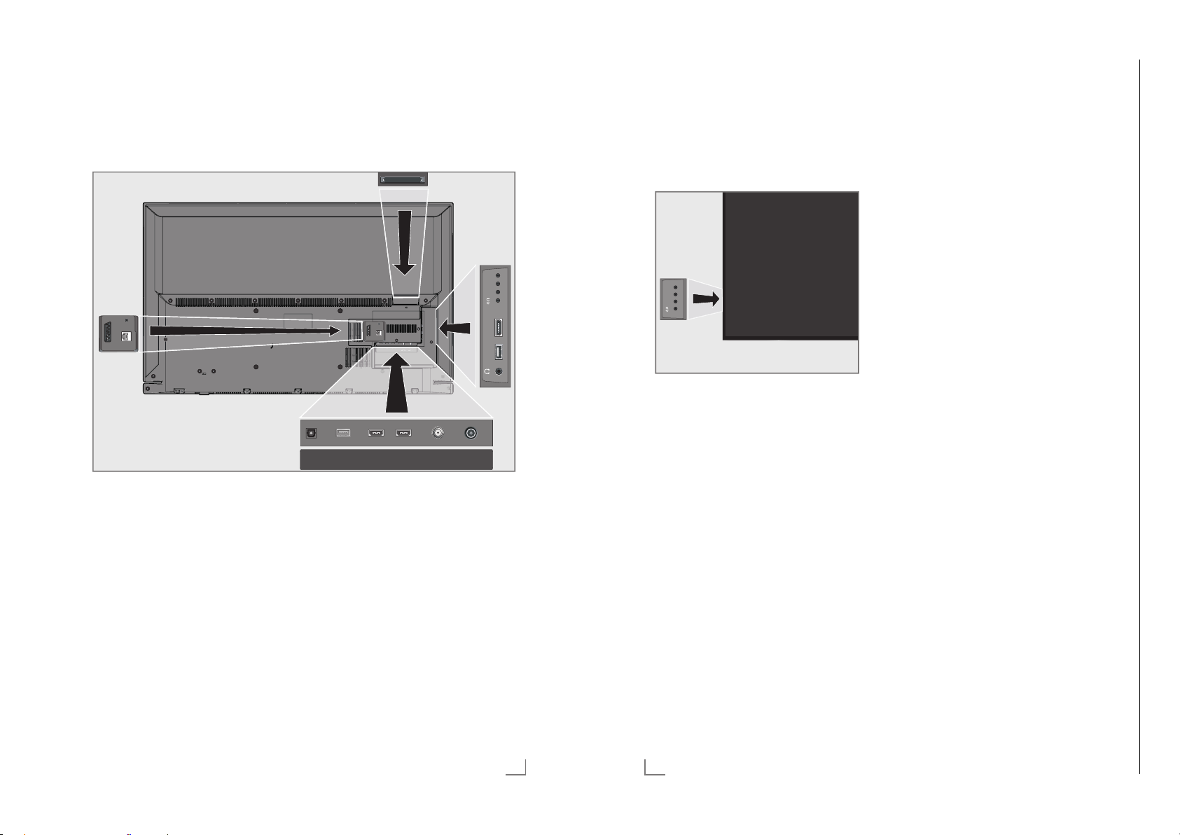
Operating Hints This chapter contains excerpts from the operating instructions. For further particulars please refer to the appropriate user instructions which can be downloaded by www.grundig.com, submenu Downloads/Manuals.
Chassis G5GRUNDIG Service
1 - 27
OVERVIEW
--------------------------------------------------------------------------------------------------------------
Connections on the television set
SERVICE
AV / S-VHS/COMPONENT
LAN
LAN Network cable connection
AV / S-VHS / COMPONENT
Euro/AV socket (CVBS
SERVICE Service only.
Optic Out Audio output sockets (opti-
It is for digital multichannel
USB(HDD) USB Harddisk socket for
socket.
signal, RGB signal);
video signal input for
S-Video camera (with ScartS-VHS converter);
Video signal input (YUV signal with Scart-YUV converter).
cal) for PCM/Dolby Digital
signals.
audio/video amplifier or
AV receiver connections.
external data medium and
PVR function;
connection for wireless
keyboard, mouse.
SERVICE
AV / S-VHS/COMPONENT
LAN
Optic Out SATELLITE
HDMI2HDMI3(ARC)USB(HDD)
13/18V
max.500mA
ANT-IN
5V
max.50mA
HDMI3 (ARC) HDMI socket, audio/video
signal input (HDMI).
HDMI2 HDMI socket, audio/video
signal input (HDMI).
SATELLITE Satellite antenna socket.
ANT-IN Antenna socket.
U Headphone connection
(3.5 mm jack);
external audio output (with
headphone-RCA converter).
USB1 USB Harddisk socket for
HDMI1 HDMI socket, audio/video
CI Common interface slot.
external data medium and
PVR function;
connection for wireless
keyboard, mouse.
signal input (HDMI).
ENGLISH
OVERVIEW
--------------------------------------------------------------------------------------------------------------
Control buttons on the TV
Control elements
+V/P-
USB1 HDMI1 +V/P-
Turning the TV to standby
1 »8/I« Switches the television on and back
into standby mode.
Adjusting the volume or changing the
station
1 »V/P« Pre-selection for volume or channel
selection.
2 »–« Adjusts the volume;
13
Selects channels in s
3 »+« Adjusts the volume;
Selects channels in s
14
ENGLISH
teps.
teps.
Page 28
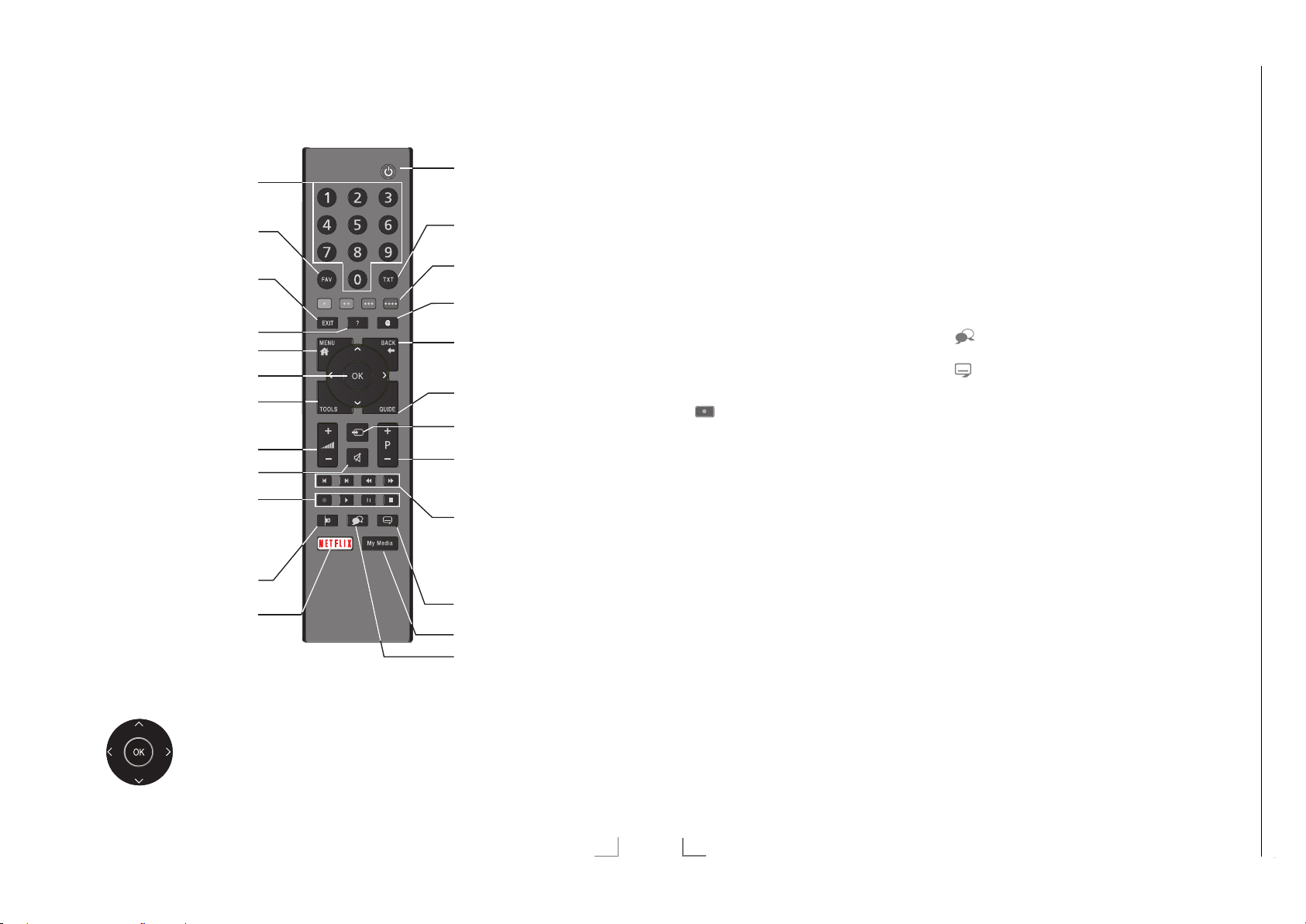
Chassis KPGRUNDIG Service
1 - 28
OVERVIEW
Chassis G5GRUNDIG Service
1 - 28
--------------------------------------------------------------------------------------------------------------
OVERVIEW
--------------------------------------------------------------------------------------------------------------
Remote control - main functions
Switches on from standby
mode;
selects channels directly
Selects the channel list
(»ALL«, »FAV 1« to
»FAV 4«)
Exits menu and applica-
tions
Displays information
Opens the menu
Opens the channel list
Opens the Tools menu
Adjusts the volume
Turns volume on/off (mute)
Record, playback, pause
or stop (only digital televi-
sion channels);
teletext on half screen
Turns on and off the
television set (stand-by)
Switches between teletext
and TV modes
Functions according to
the screen help, HbbTV
Opens MyApps menu
Zapping function;
switches t
he menus back
one menu level
Opens the electronic TV
guide
Signal source
Switches on from standby;
selects stations step by step
Next/previous image/
chapter, next/previous
track
Remote control - all functions
(red) Selects a page in teletext mode;
y
(green) selects/activates various functions
yy
(yellow) in menus.
yyy
(blue)
yyyy
5 Switches to double character size
6 Updates a page in teletext mode;
3
Page hold in teletext mode;
4
Show answers in teletext mode;
8 Starts playback in the external
in teletext mode;
selects the previous track/previous
picture in the Media Player.
selects the next track/next picture
in the Media Player.
starts the reverse picture search in
the Media Player.
starts the forward picture search in
the Media Player.
Starts recording (in digital TV op-
eration, recording only via external
data media).
data media;
Starts playback in the DLNA menu.
! Time shift during live signal (in digi-
7 Selects the split screen function in
Selects different subtitles (in digital
Note:
7
Depending on the features of your TV, you
tal TV operation, only via external
data media);
pauses the file executed on the
external data media;
pauses the file executed on the
DLNA menu.
teletext mode;
ends playback in the file browser;
ends recording or playback in the
PVR mode;
stops the file executed on the
DLNA menu.
Selects different audio language
(in digital TV operation).
TV operation).
Your TV supports remote control feature for
Apple iPhones, Windows mobile phones
and Android phones.
may control your TV by your phone after
downloading the free »GRUNDIG TV
Remote« application from Apple App. Store
or Google Play (Android Market).
No function
Opens Netflix applications
Cursor Control
Moves the cursor up and
do
wn in the menus.
Moves the cursor left/right in
menus.
Opens channel list;
activates various functions.
Select subtitle
Opens Media Player menu
Select audio channel
ENGLISH
15
16
ENGLISH
Page 29

Chassis G5GRUNDIG Service
1 - 29
INITIAL SET-UP
---------------------------------------------------------------------------------------------------
INITIAL SET-UP
---------------------------------------------------------------------------------------------------
Arrange Initial set-up
1 Switch on the television set from standby
with »
– Menu Language menu appears when the
2 Select the menu language with »
– »Welcome« menu appears.
3 Step-by-step installation will be made to be
4 Select the country in which the television
5 Confirm the option »Home Mode« with
or
– »Home Mode« contains preconfigured
– »Enhanced« – if you will use the television
8«, »1…0«, »P+« or »P–«.
device is switched on for the first time.
Smart Inter@ctive 4.0
Please select your desired language
Menu Language
Česky Dansk Deutsch English Espanol
Hrvatski Italiano Magyar Nederlands Norsk Polski Português
Pyccкий Româneşte Slovenščina Eesti Suomi Svenska Бългaрски
Slovenčina Lietuviu Türkçe
Navigation Between Items
English
Select
Help:
7
If the »Menu Language« menu does not
appear on the screen, make the setting by
following the instructions on returning the
television to its factory settings on page 76.
»
V
« or »Λ« and press »OK« to confirm.
able to use t
tart the installation.
s
set is oper
he television. Press »OK« to
ated with »
and press »OK« to confirm.
– »User Mode« menu appears, the option
»Home Mode« is selected.
»OK«;
select the option »Enhanced« with »
»
Λ
« and press »OK« to confirm.
TV settings that provide energy savings
conforming EUP.
for a demo presentation, increased image
and volume settings are used in this mode.
Increased mode consumes more energy.
Eλληvıκά
Français
«, »>«,
<
«, »>«, »V« or »Λ«
<
V
« or
6 Select the required option »Stand« or »Wall-
mounted« with »
V
« or »Λ«.
Note:
7
The information how to place the television
set is important for the automatic audio
settings.
7 Confirm setting with »OK«.
– The »Summary« menu will be displayed.
8 Select the next operating step with »
yyyy
«
(blue).
– The »Accessories« menu will be dis-
played.
9 If an accessory is used for the television and
eady been connected, carry out the
it has alr
required settings in this menu.
Select accessory with »
select setting with »
10 Select the next operating step with »
V
« or »>«.
<
« or »Λ« and
yyyy
«
(blue).
Note:
7
If you want to connect your television to the
home network,
– continue at point 12 for an automatic
AN connection, or
L
– continue at point 17 for an automatic
WL
AN connection.
Note:
7
If connecting to a home network is not nec-
essary, skip the setting using »
yyyy
« (blue).
Continue settings at point. 25, 29 or 34.
Connecting to a home network with a
LAN cable
11 Confirm »Change Connection Type« with
»OK«.
V
12 Select the option »Wired« with »
« or »Λ«
and press »OK« to confirm.
Note:
7
The settings for a manual LAN connection
are on page 88.
13 Press »y« (red) to select »Connect« option to
tablish modem connection.
es
– »Connecting ... Please wait« message
will be displayed, and if the connection
is established »Connection To Gateway:
Success« messages will be displayed.
14 Press »yy« (green) to check the performed
settings and also if the local network and
internet connection has been established.
– »Testing ... Please wait« message will
be displayed, and if the connection is
established »Connection To Gateway:
Success«, »Internet Connection: Success«
messages will be displayed.
15 To switch to »Source« menu press »
yyyy
«
(blue).
Note:
7
Continue searching for TV channels with:
– point 25 for DVB-S reception;
–
point 29 for DVB-C reception;
point 34 for DVB-T reception.
–
Connecting automatically by entering
the network password
16 Confirm »Change Connection Type« with
»OK«.
V
17 Select the option »Wireless« with »
»
Λ
« and press »OK« to confirm.
« or
18 Confirm the message »Do you want to turn
on Wi-F
i?« select »Yes« with »
press »OK« to confirm.
« or »>« and
<
19 Select the line »Select Access Point« with
»
V
« or »Λ« and press »OK« to confirm.
– »Select Access Point« menu appears and
available wireless networks are scanned
and displayed in the menu.
20 Select the network that you want to con-
V
« or »Λ« and press »OK« to
h »
nect wit
confirm.
– Wireless connection password screen is
displayed.
V
21 Select the required character with »
»
Λ
«, »<« or »>« and move to the next
«,
character with »OK«.
– Using »Shift« ° »OK«, you can switch
betw
een uppercase letters / numbers and
lowercase letters / special characters.
– Select »Del« to delete the character
entered and press »OK« to confirm.
22 Confirm the password with »yy« (green).
– »Connecting ... Please wait« message
will be displayed, and if the connection
is established »Connection To Gateway:
Success« messages will be displayed.
23 Press »yy« (green) to check the performed
settings and also if t
he local network and
internet connection has been established.
– »Testing ... Please wait« message will
be displayed, and if the connection is
established »Connection To Gateway:
Success«, »Internet Connection: Success«
messages will be displayed.
24 To switch to »Source Setup« menu press
»
« (blue).
yyyy
Note:
7
Continue searching for TV channels with:
– point 25 for DVB-S reception;
–
point 29 for DVB-C reception;
point 34 for DVB-T reception.
–
ENGLISH
19
20
ENGLISH
Page 30

INITIAL SET-UP
Chassis G5GRUNDIG Service
1 - 30
---------------------------------------------------------------------------------------------------
INITIAL SET-UP
---------------------------------------------------------------------------------------------------
Searching television channels with satellite signal (DVB-S)
25 Select the option »Satellite (DVB-S/S2)«
with »
V
« or »Λ« and press »OK« to
confirm.
– The satellite Astra 19.2° East is preset.
26 Confirm the push button »Continue« with
»
« (blue).
yyyy
Notes:
7
Select the Channel Type.
Press »
V
« or »Λ« to select whether you
want to search for only digital channels
(Digital) or only radio channels (Radio) or
both (Digital + Radio) and press »OK« to
select and mar
k or unmark the »Digital«
and/or »Radio« items.
7
Select Scan Mode.
To select whether you want to search for
only free digital television channels (Free),
only scrambled digital television channels
(Scrambled) or both (Free + Scrambled),
press »
V
« or »Λ« and press »OK« to
select and mark or unmark the »Free« and/
or »Scrambled« items.
27 Press »y« (red) to start searching.
– »Digital Searching« menu appears and
the scan for TV channels begins.
– The scan is complete as soon as the mes-
sage »Search is completed!« appears.
28 Select the »Channel Editor« with »OK«.
Tuning cable digital television channels
(DVB-C)
29 Select the option »Cable (DVB-C)« with
»
V
« or »Λ« and press »OK« to confirm.
V
30 Select the line »Scan Type« with »
»
Λ
«.
Select the option »Quick« or »Full« with »
or »
«.
>
– »Quick« scanning function sets the chan-
« or
<
nels according to the cable operator
information in the broadcasting signal.
– »Full« scan function scans the entire fre-
quency range selected. With this search
option, search can take a long time. This
search type is recommended. Some cable
providers do not support »Quick« scan.
Note:
7
You can speed up the search. To do this,
frequency and network ID information are
required. You may get this data from your
cable operator or find it in the Internet
forums.
31 Confirm the push button »Continue« with
»
« (blue).
yyyy
Note:
7
Perform Channel Type selection. Press
»
V
« or »Λ« to select whether you want to
search for only digital channels (Digital),
only Analog channels (Analog) or both
(Digital + Analog) and press »OK« to se-
lect and mar
k or unmark the »Digital« and
»Analog« items.
32 Press »y« (red) to start searching.
– The »Digital or Analog Searching« menu
appears, and the search for TV channels
begins.
– The scan is complete as soon as the
»Search is completed!« appears.
33 Select the »Channel Editor« with »OK«.
Tuning terrestrial digital television
channels (DVB-T)
34 Select the option »Air (DVB-T/T2)« with
»
V
« or »Λ« and press »OK« to confirm.
Important:
7
«
The antenna power supply (5V ) may
only be switched on if the antenna is an
active indoor antenna with a signal
amplifier and it is not already supplied with
a voltage via a mains plug (or similar
supply). Otherwise you may cause a short
circuit and irreparably damage your
antenna.
35 Select the line »Active Antenna Power« with
»
V
« or »Λ«.
Switch on the antenna power supply for the
antenna with »
36 Select the line »Next Page« with »
»
Λ
« and press »OK« to confirm.
« or »>« (»On«).
<
V
« or
Note:
7
Perform Channel Type selection. Press
»
V
« or »Λ« to select whether you want to
search for only digital channels (Digital),
only Analog channels (Analog) or both
(Digital + Analog) and press »OK« to se-
lect and mar
k or unmark the »Digital« and
»Analog« items.
37 Press »y« (red) to start searching.
– The »Digital or Analog Searching« menu
appears, and the search for TV channels
begins.
– The scan is complete as soon as the
»Search is completed!« appears.
38 Select the »Channel Editor« with »OK«.
ENGLISH
21
22
ENGLISH
Page 31
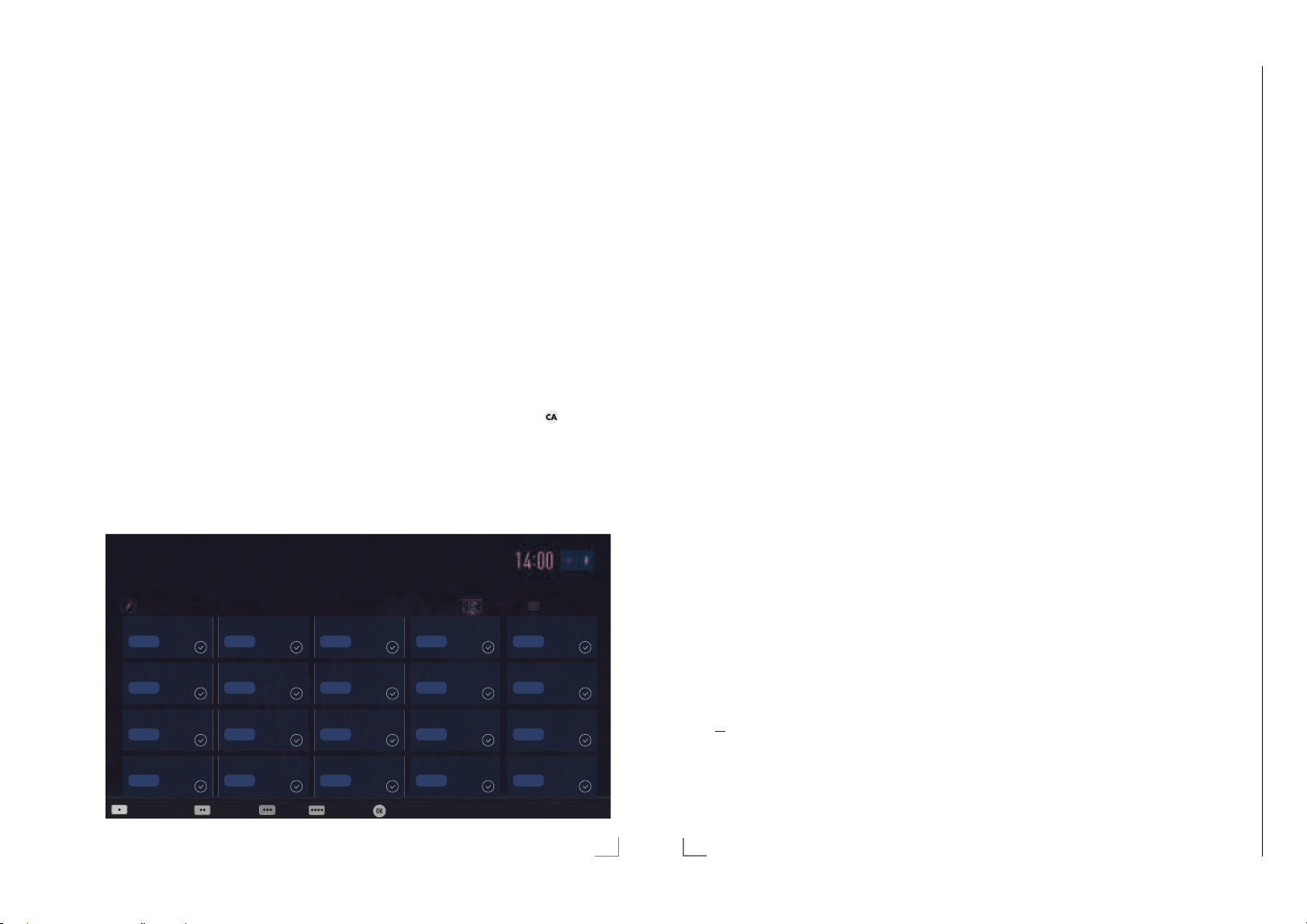
INITIAL SET-UP
Chassis G5GRUNDIG Service
1 - 31
---------------------------------------------------------------------------------------------------
INITIAL SET-UP
---------------------------------------------------------------------------------------------------
Changing the Channel Editor for
the digital channels
Channels found at the end of the search are
stored in the »Channel Editor«.
You can delete channels which are not required
from the programe table, you can change the
order of channels within the programe table and
lock individual channels (Parental control).
You can also add channels to the favourites list;
in addition, you can change the order of channels within the favourites list.
In Channel Editor, press »P+« to switch the
channel lis
switch it back to t
To perform searching in the Channel Editor
menu by Channel names, press »y« (red).
T
menu, press »
t to the next page, press »P–« to
he previous page.
o use filters and tools in the Channel Editor
« (yellow).
yyy
1 Das Erste
Channel Editor
1 Das Erste
DTV
6 24
DTV
11 HD1
DTV
16 TV Sport
DTV
Search for Channels Antenna Type Tools Tune Channel Select
2 ZDF
DTV
7 HD Sports
DTV
12 Life
DTV
17 SAT8
DTV
3 SAT1
DTV
8 HD Test
DTV
13 Film
DTV
18 SKY
DTV
Opening the Programme Table
1 Open the menu with »MENU«.
V
2 Select the »Settings« menu with »
»
« or »>« and press »OK« to confirm.
<
3 Select the option »Source« with »
and press »
V
« to confirm.
«, »Λ«,
« or »<«
>
4 Select the line »Channel Editor« with »
and press »OK« to confirm.
– »Channel Editor« menu is displayed.
Important:
7
Programme table and favourite lists are
stored separately for all sources (satellite,
cable and air).
7
Programme table of the current source will
be displayed when you select programme
table.
Notes:
7
A Cl module and smart card is required to
watch the channel if there is a »
« sign
next to the channel name in Programme
Table.
7
As the recorded data channels are not
displayed in the channel list, number of
channels displayed in the Channel list may
be less than 6000
Tuesday
xx xxx xxxx
Satellite All
4 N24
DTV
8 SAT
DTV
12 Promo
DTV
19 TV6
DTV
5 SAT3
DTV
10 RTL
DTV
15 Sport1
DTV
20 TV5
DTV
Searching channels by name in the
Channel Editor
While arranging the channels in the Channel
Editor, you can search and select the channel
name by the first three characters.
1 In the »Channel Editor« menu, select the
sear
V
«
ch mode by pressing »y« (red).
2 Select the first character of the channel
name y
ou want to search with »
»
« or »>« and press »OK« to confirm.
<
Repeat the entry for the next characters.
V
«, »Λ«,
– Channels found will be listed on the right
side of the screen.
3 With »
« switch to result section, select the
>
channel you are searching with »
»
Λ
«, and highlight this with »OK«.
V
« or
Note:
7
To change the place of, delete or add the
channels to favorites lists, continue reading
the relevant section.
4 To return to the previous menu, press
»BACK <«.
5 To exit the »Channel Editor« menu, press
»EXIT«.
Deleting channels in the Channel
Editor
1 In the »Channel Editor« menu, select the
channel(s) you want to delete with »
»
Λ
«, »<« or »>«, and highlight the channel
V
«,
by pressing »OK«.
– Channel is marked with »«.
2 Press »
– »Tools« menu is displayed.
3 Select the line »Delete« with »
« (yellow).
yyy
V
« or »Λ«
and press »OK« to confirm.
4 To confirm deletion process, select the op-
tion »OK« wit
h »
« or »>«;
<
Moving the channels in the channel organizer to different channel positions
1 In the »Channel Editor« menu, select the
channel(s) you want to move with »
»
Λ
«, »<« or »>«, and highlight the televi-
V
«,
sion channel by pressing »OK«.
– Channel is marked with »«.
2 Press »yy« (green).
Notes:
7
In case of changing the order of the channels, channel numbers sent by the broadcaster will be changed.
7
If more than one channel is selected for
moving, channels will be moved one after
the other according to the selection order of
channels.
3 Select the new place of the channel with
»
V
«, »Λ«, »<« or »>« and press »OK« to
confirm.
4 To exit the »Channel Editor« menu, press
»EXIT«.
Displaying channels in the Channel
Editor by antenna type
If you have more than one antenna type, you
can display channels in the Channel Editor by
antenna type.
1 To display the channels in the »Channel
Editor« menu b
(y
ellow).
y antenna type, press »
yyy
2 Confirm »Antenna Type« with »OK«.
3 Select »Air«, »Cable« or »Satellite« with
V
« or »Λ« and press »OK«.
»
– Television will switch to the antenna sys-
tem you have selected and channels will
be displayed.
4 To exit the »Channel Editor« menu, press
»EXIT«.
«
or
to cancel deletion process, select the option
»No« with »
confirm.
5 To exit the »Channel Editor« menu, press
« or »>« and press »OK« to
<
»EXIT«.
ENGLISH
23
24
ENGLISH
Page 32

INITIAL SET-UP
Chassis G5GRUNDIG Service
1 - 32
---------------------------------------------------------------------------------------------------
INITIAL SET-UP
---------------------------------------------------------------------------------------------------
Sequencing channels in the Channel
Editor
You can sequence the channels in the Channel
Editor according to different criteria such as TV,
radio or scrambled / unscrambled.
1 To sequence the channels according to dif-
fer
ent criteria in the »Channel Editor« menu,
press »
« (yellow).
yyy
2 Select the sequencing criteria you want with
»
V
« or »Λ« and press »OK« to confirm.
– Channels will be displayed in the »Chan-
nel Editor« menu by the criteria you have
selected.
3 To exit the »Channel Editor« menu, press
»EXIT«.
Creating a list of favourites
You can select your favourite channels and save
them in up to four lists (FAV1 to FAV4).
Note:
7
Favourite lists must be created separately
for all sources (satellite, cable and air).
7
After created the favourite list, press »FAV«
to select the favorite list.
1 In the »Channel Editor« menu, select the
channel(s) y
ites list with »
ou want to add in the favor-
V
«, »Λ«, »<« or »>«, and
highlight the television channel by pressing
»OK«.
– Channel is marked with »«.
2 Press »
– »Tools« menu is displayed.
3 Select the line »Add to Fav.« with »
»
Λ
« (yellow).
yyy
« and press »OK« to confirm.
V
« or
–»Add to Fav.« menu is displayed.
4 Select the favorite list you want to add the
V
selected channels wit
« or »Λ« and
h »
store with »OK«.
– The channels are marked in the Channel
Editor with »«, »«, »« or »«.
– You can add the same channel in more
than one favourites list.
– Each favourite list can contain maximum
255 channels.
Notes:
7
You can delete channels from the favourites
list.
Press »
lis
« (yellow), select the favorites
yyy
t the channel is in with »
V
« or »Λ« and
press »OK« to confirm.
Select t
he channel(s) you want to delete
with »
V
«, »Λ«, »<« or »>«, and highlight
the channel by pressing »OK«.
Pr
ess »
« (yellow) and select the line
yyy
emove from Fav.« with »
»R
V
«, »Λ« and
confirm with »OK«.
7
When a channel stored in the favourite
channel list is deleted channel order in the
favourite list is updated.
5 To exit the »Channel Editor« menu, press
»EXIT«.
Sorting channels in the favorites list
You can change the channel sorting in the
favorites list.
1 To select favorites list in the »Channel Edi-
ess »
tor« pr
« (yellow).
yyy
2 Select the favorites list you want to sort with
V
« or »Λ« and press »OK« to confirm.
»
3 Select the channel(s) you want to move with
V
«, »Λ«, »<« or »>«, and highlight the
»
television channel by pressing »OK«.
– Channel is marked with »«.
4 Press »yy« (green).
Note:
7
If more than one channel is selected for
moving, channels will be moved one after
the other according to the selection order of
channels.
5 Select the new place of the channel with
»
V
«, »Λ«, »<« or »>« and press »OK« to
confirm.
6 To exit the »Channel Editor« menu, press
»EXIT«.
Enter own names for the favourites lists
(max. 6 characters)
You can rename all favorites lists.
1 To recall favorites list menu when no menu is
opened on t
he screen, press »FAV«.
2 Select the favorites list you want to rename
V
« or »Λ« and press »
h »
wit
yyyy
« (blue)
button.
– Virtual keyboard will be displayed.
3 To delete the current name step by step,
pr
ess »y« (red).
4 Select the required character/number with
V
«, »Λ«, »<« or »>« and move to the
»
next character with »OK«.
Repeat the same process for all characters/
numbers.
Note:
7
Using »Shift« ° »OK«, you can switch
between uppercase letters / numbers and
lowercase letters / special characters.
5 To save the new name with »yy« (green).
6 Press »EXIT« to end the setting.
Renaming AV channels
You can rename AV channels according to the
device you have connected. For example, for a
PC which you have connected to HDMI1 source
of TV with HDMI cable, you can name the
source as PC.
1 Open »Input Source« menu with »
«.
2 Select the AV source you will rename with
« or »>« and press »
»
<
– Rename menu is displayed.
yyyy
« (blue).
3 Press »OK« and delete the “old” name step
y step with »y« (red).
b
4 Select the required character/number with
V
«, »Λ«, »<« or »>« and move to the
»
next character with »OK«.
Repeat the same process for all characters/
numbers.
Note:
7
Using »Shift« ° »OK«, you can switch
between uppercase letters / numbers and
lowercase letters / special characters.
5 To save the new name with »yy« (green).
6 Select the icon appropriate for the device
ype with »
t
confirm
7 To save the setting, press »
– Source name and icon will change.
« or »>« and press »OK« to
<
« (blue).
yyyy
8 Press »EXIT« to end the setting.
ENGLISH
25
26
ENGLISH
Page 33
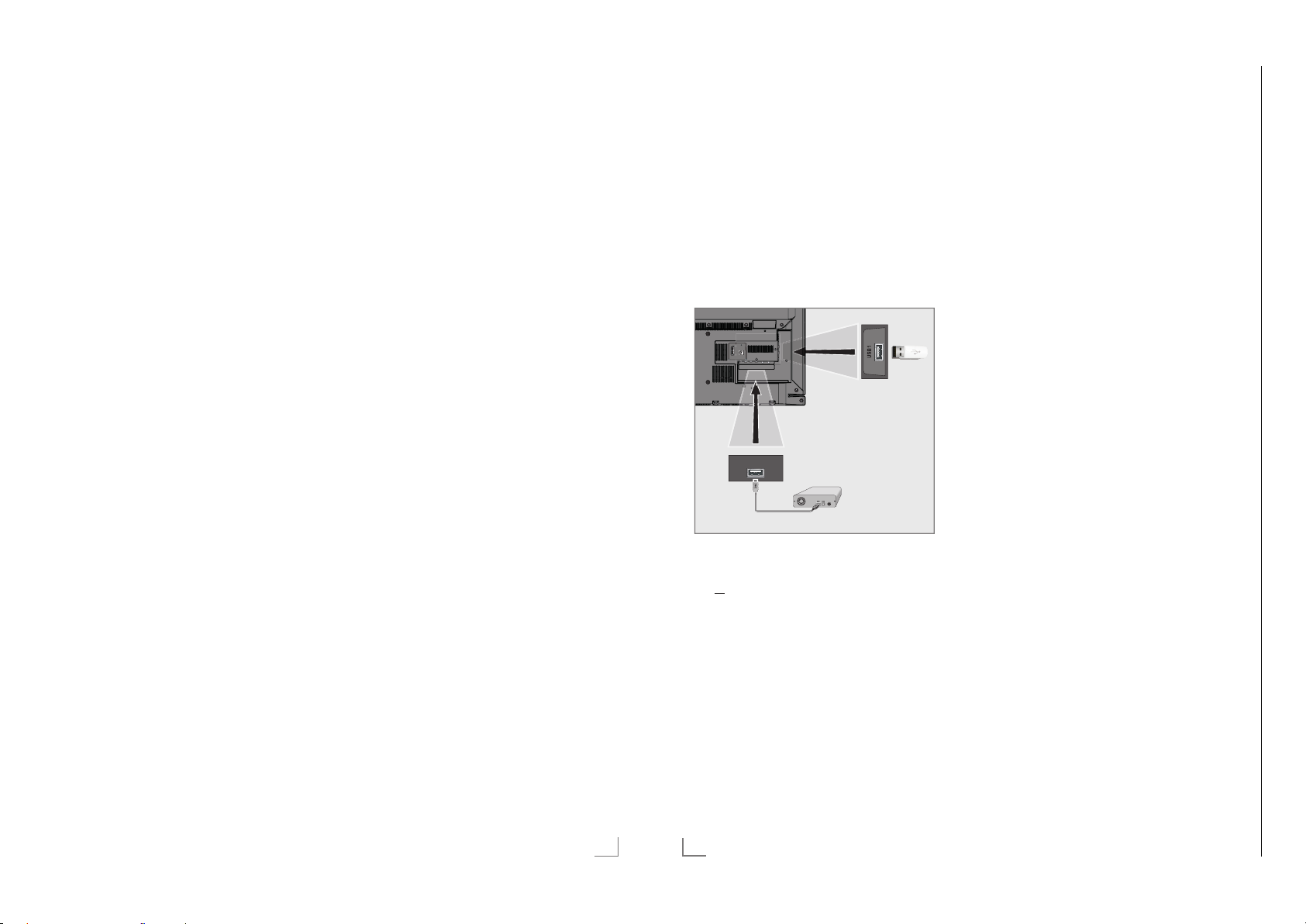
HBBTV MODE
Chassis G5GRUNDIG Service
1 - 33
------------------------------------------------------------------------------------------------------
USB RECORDING
-------------------------------------------------------------------------------------------
Using HbbTV
When you switch to a TV program that supports
HbbTV, an info message will appear stating that
HbbTV broadcast is available.
1 Press »y« (red) to open HbbTV.
– Information regarding the services will ap-
pear on the screen. Additionally, colored
buttons necessary for browsing the menus
will also appear.
Notes:
7
The range of subjects and selection of individual subjects depend on the programme
provider.
7
Numeric buttons »1« through »0« are used
for additional functions.
2 Press »yy« (green), »
(blue) or »
V
«, »Λ«, »<« or »>« and
« (yellow) or »
yyy
yyyy
confirm with »OK« to select the desired
topic f
ield.
V
3 Select the option you want with »
»
« or »>« in the selected topic field and
<
confirm with »OK«.
«, »Λ«,
4 Press »y« (red) to close HbbTV.
Note:
7
If the navigation in HbbTV mode does not
work, you can exit the function by pressing
»EXIT«.
Additional functions for video
indexes
1 Start playback with »8«.
2 Pause playback with »
3 Resume playback with »
4 Rewind by »
3
5 Stop playback with »
!«.
8«.
« forward by »4«.
7«.
Deactivate and activate HbbTV
This option allows turning off Hbb TV feature,
thus warnings shall not be displayed on channels with Hbb TV feature.
1 Open the menu with »MENU«.
2 Select menu item »Settings« with »
»
« or »>« and press »OK« to confirm.
<
3 Select the menu item »Source« with »
»
« and press »V« to confirm.
<
– »Source« menu is active.
4 Select the line »Advanced« with »
»
Λ
« and press »OK« to confirm.
5 Select the line »Hbb TV« with »
6 Select the option »Off« with »
«
Note:
7
To activate HbbTV again, select in step. 6
<
the option »On«.
7 Press »EXIT« to end the setting.
Deactivate and activate digital
teletext
If you deactivate digital video text, only normal
video text can be selected, however the other
functions of the interactive service HbbTV are
still available.
1 Open the menu with »MENU«.
2 Select menu item »Settings« with »
»
« or »>« and press »OK« to confirm.
<
3 Select the menu item »Source« with »
»
« and press »V« to confirm.
<
– »Source« menu is active.
4 Select the line »Advanced« with »
»
Λ
« and press »OK« to confirm.
5 Select the line »Digital Teletext« with »
or »
Λ
«.
6 Select the option »Off« with »
Note:
7
To reactivate digital teletext, select »On« in
step 6.
7 Press »EXIT« to end the setting.
<
V
«, »Λ«,
>
V
« or
V
« or »Λ«.
« or »>«.
V
«, »Λ«,
>
V
« or
« or »>«.
« or
« or
V
Connecting external data media
Notes:
7
It is advised to put the television on stand-by
mode before connecting the Skype camera.
7
Before disconnecting the external data medium, the television must first be switched to
standby, otherwise files can be damaged.
7
There are two USB inputs on the television,
namely USB(HDD) and USB1.
USB1(HDD) input is intended for USB
de
vices that require additional power (e.g.
external hard disk).
Notes:
7
The socket USB1 of the television supports
500 mA current according to the USB
standard. Devices such as external hard
disk and etc. that consume more power can
only be connected to the USB(HDD) USB
face of the television.
inter
7
If you are using a power cable for the
external hard disk that you have connected
to the USB(HDD) USB interface, then the
wer cable of the external hard disk must
po
also be unplugged when the TV is turned
off.
7
You must not disconnect the USB Device
from the TV while a file on the USB Device
AV / S-VHS/COMPONENT
SERVICE
LAN
Optic Out USB(HDD)
HDMI3(ARC)
HDMI2
USB(HDD)
ANT-IN
SATELLITE
5V
13/18V
max. 50mA
max. 500mA
is being read by the TV.
1 Plug the external hard disk to the
USB(HDD) USB interface of the television;
or
plug the memory stick in the USB1 socket
of t
he television.
«
ENGLISH
39
42
ENGLISH
Page 34

USB RECORDING
Chassis G5GRUNDIG Service
1 - 34
-------------------------------------------------------------------------------------------
USB RECORDING
-------------------------------------------------------------------------------------------
USB recording settings
Selecting the menu
1 Open the menu with »MENU«.
2 Select the menu item »Records« with »
»
Λ
«, »<« or »>« and press »OK« to
confirm.
– »Media Player« menu is displayed.
3 Select the line »PVR« with »
V
press »OK« to confirm.
– The content is displayed.
4 Open the Media Options menu with press
»TOOLS«.
Media Player > PVR
Channel_1_201548_154649.ts
Media Options
View Mode Auto Fit
Auto Preview On
Slide Show Interval 5
Disk Management
5 Select the line »Disk Management« with
»
V
« or »Λ« and press »OK« to confirm.
Note:
7
Additional operations are explained in the
following sections.
Disconnecting external data media
1 In the »Disk Management« menu select
the line »Safely Remove Disk« with »
»
Λ
« and press »OK« to confirm.
Note:
7
Disk can be safely removed from the socket
now.
V
« or »Λ« and
Tuesday
xx xxx xxxx
Back
BACK
V
« or
Selecting external data media
If there are more than one external data media
connected to the television, then select one of
them.
1 In the »Disk Management« menu select the
«,
line »Disk« wit
V
« or »Λ« and press
h »
»OK« to confirm.
2 Select the external data media with »
or »
Λ
«.
3 Switch back with »BACK <« or press
»EXIT« to end the setting.
Selecting a partition on the external
media
If there are more than one partitions on the
external data media, select one of them.
1 In the »Disk Management« menu select the
V
line »P
artition« with »
« or »Λ« and press
»OK« to confirm.
2 Select the desired partition with »
»
Λ
«.
3 Switch back with »BACK <« or press
»EXIT« to end the setting.
Testing external data media
You can test the external data media to see if it
is suitable for the required functions.
1 In the »Disk Management« menu select the
V
« or »Λ«. If there are
line »Disk« wit
h »
more then one external data media, select
the desired data media with »
2 Select the line »Partition« with »
If there are more then one partitions, select
the desired partition with »
3 Select the line »Check Disk« with »
»
Λ
« and press »OK« to confirm
– Disk information is displayed.
4 Switch back with »BACK <« or press
»EXIT« to end the setting.
V
V
« or »Λ«.
V
V
« or
« or »Λ«.
V
« or »Λ«.
V
« or
Formatting the partition
1 In the »Disk Management« menu select the
line »Format Partition« with »
V
« or »Λ«
and press »OK« to confirm.
2 Select push button »Yes« with »
confirm the security query;
« or »>« to
<
or
«
select push button »No« with »
to cancel the function.
« or »>« to
<
3 Switch back with »BACK <« press »EXIT«
he setting.
to end t
Time shift – ″ Pausing”
programmes
You can pause any program you are watching. This is a useful function. For instance, if the
phone rings when you are watching a movie,
you can pause the movie and resume it after the
call without missing nothing.
The last scene that was frozen is displayed and
time shift is recorded into the external data
media.
In Time Shift mode, you can only record as
much as the free memory space on the external
data media.
You can record current broadcast for approximately 60 minutes.
Note:
7
For undisturbed “Permanent Timeshift” use
an external USB hard disk.
1 Press »
!« during the broadcast.
– Television picture is paused and delay
time is displayed.
2 To resume the broadcast, press »
8«.
– The system continues recording the broad-
cast while you are watching it.
Note:
7
Following functions can be used in time shift
mode.
–
Fast rewind, press »3« several times for
the desired speed;
–
Fast forward, press »4« several times for
the desired speed;
–
To pause press »!«.
3 Press »
7« to exit the Time Shift function.
– The message »Live Broadcast« appears.
– The scenes in the “time shift memory” are
deleted.
ENGLISH
43
44
ENGLISH
Page 35

Chassis G5GRUNDIG Service
1 - 35
USB RECORDING
-------------------------------------------------------------------------------------------
Recording programmes
You can record the programmes. Programmes
are recorded onto the external data media and
the archive is managed via television.
A memory of 44 MB up to 110 MB is required
for a 1 minute record.
Other recordings in the archive can be watched
while a programme is being recorded.
It is possible to shift channels during recording
between unscrambled channels on the same
frequency (DVB-T/C) or on the same transponder (DVB-S).
When switched to channels other than (Terrestrial, Cable, Satellite and USB) during recording, the recording process is stopped.
One-touch programme recording
1 Select the channel with »1…0« or »P+«,
»P–« and press »
ing.
– Recording information is displayed:
Recording symbol, channel name, programme time and recording time.
– This information will disappear shortly.
2 To end the recording, press »
3 Select push button »Yes« with »
confirm the security query;
or
select push button »No« with »
to continue the recording.
Notes:
7
When recording is complete, it will automatically be stored on the external data
media.
7
If you remove the external data media
during recording, then the recording is
cancelled automatically and no data is
recorded onto the external data media.
« to start the record-
7«.
« or »>« to
<
« or »>« to
<
Recording a programme from
the channel list
1 Press »OK« to open the channel list.
2 Select a channel with »
»OK« to confirm.
3 Press »EXIT« to exit from the channel list.
4 Press »
– Recording information is displayed:
– These information will disappear after a
5 To end the recording, press »
6 Select push button »Yes« with »
confirm the security query;
or
select push button »No« with »
continue the recording.
« to start recording.
Recording symbol, channel name, programme time and recording time.
short while. Recording symbol and recording time will appear on the lower right
corner of the screen.
« or »>« and press
<
7«.
« or »>« to
<
« or »>« to
<
SMART INTER@CTIVE TV 4.0 FEATURE
7
SMART Inter@ctive TV 4.0 internet applications
Smart Inter@ctive TV 4.0 interactive applications
provide your television with Internet services
and pages.
These applications are designed according to
your television.
With SMART Inter@ctive TV 4.0 feature you can
run many local and global internet applications. Thanks to Grundig Application Store, you
can find many applications that you may use
on your Grundig TV. You can download many
applications from Grundig Application Store.
These applications include video, picture, music,
social networking applications, news and sports
applications, weather forecast applications and
some specific applications.
Notes:
7
Availability of SMART Inter@ctive TV 4.0,
inter@ctive applications may vary from one
country to the other.
7
Smart Inter@ctive TV 4.0 cannot download
and save files, cannot upload files to a web
site and cannot install add-ins except Login
pages of some applications for applications
other than the ones in Grundig Smart Apps.
7
Grundig is not responsible for the content
and the quality of content offered by the
content providers.
7
Local and global internet applications
provided through your Smart Inter@ctive TV
4.0 comes with your TV within the framework of special limited duration agreements
entered into with the application owners.
Application owners may update, modify,
restrict or entirely remove those applications
with their own decision. Grundig cannot be
held responsible for such changes.
7
Grundig reserves the right to make all
changes such as modifications, restrictions, extensions, transfers and removals on
internet applications provided through your
SMART Inter@ctive TV 4.0.
In Login process of some applications, it
may be required to connect to the web
page of the related application. Subject
web pages may contain links not related
to Login process. When connecting those
links, TV may access open web and view
contents that are not supported by your TV.
As you are on open web, your TV cannot
control those unsupported contents or cannot be held responsible for them.
USB keyboard and mouse
You may connect a keyboard or mouse to both
sockets USB(HDD) or socket USB1 to use in
the Web browser. Keyboards and mice requiring special drive are not supported.
Starting Smart Inter@ctive TV
1 Open the menu with »MENU«.
2 Select the menu item »Applications Store«
Notes:
7
7
7
« or »>« and press »OK« to confirm
wit
h »
<
or open the menu »Applications Store« with
»@«.
– »Inter@ctive Applications« menu will be
displayed. During initial login, registration
screen for GRUNDIG Application Store
will be displayed.
If you press »@« when no menu is open,
you can access »My Apps« menu.
If you attempt to start Inter@ctive applica-
tions without a cable or wireless adapter
connected, the related warning is displayed
on the screen. If your wired or wireless
adapter is connected but you cannot
receive IP or internet is not connected, the
Inter@ctive applications cannot be started.
In this case, check Network connection settings. see. page 86 or 89.
You can find out about navigating in the
menus and how to set up access to the applications in the following chapter.
--------------------------------
ENGLISH
45
ENGLISH
57
Page 36

SMART INTER@CTIVE TV 4.0 FEATURE
Chassis G5GRUNDIG Service
1 - 36
--------------------------------
SMART INTER@CTIVE TV 4.0 FEATURE
--------------------------------
Navigation and enetering text
during registration
1 Press »@« to open »MyApps« menu.
– Grundig Smart Apps registry screen is
displayed.
Login
You need to register in order to use sart apps fully functional.
Remember me
Register Enter Skip
2 Press »V«, »Λ«, »<« or »>« and select
»Rrgister« to start registration and press
»OK«.
V
3 Select necessary text areas with »
»
« or »>« and press »OK«.
<
– Virtual keyboard will be displayed.
Notes on data entry:
7
Press »yy« (green) for keyboard language.
7
Data will be entered through virtual key-
board. Select necessary letters/numbers
and press »OK« to confirm.
7
For upper/lower case, select »Shift« and
and press »OK« to confirm.
7
Press »y« (red) to switch to mobile key-
board.
7
Press »
number. Press »
char
7
When entry is complete, use »V«, »Λ«,
»
<
and press »OK« to confirm.
Virtual keyboard will disappear.
« (blue) to delete last character/
yyyy
« (yellow) to delete all
yyy
acters.
« or »>« to select »BACK <« option
«, »Λ«,
Creating a Grundig Application
Store account
You must register to access all applications in
Grundig Application Store.
1 Press »@« to open »MyApps« menu.
– Grundig Smart App registry screen is
displayed.
V
2 Press »
»Register« to start registration and press
»OK«.
3 Enter your »Name«, »Surname«, »Phone«
(optional), »Date of Bir
Select the letters/numbers with »
»
After you’ve entered the data, use »
»
and press »OK« to confirm.
Pr
to display the keyboard.
Use »
»Next« to proceed to the next screen and
confirm with »OK«.
Note:
7
Select »Prev« to return back to previous
4 Enter Device Name, E-mail, Password entry
and conf
Select the letters/numbers with »
»
After you’ve entered the data, use »
»
and press »OK« to confirm.
Pr
to display the keyboard.
Use »
»Next« to proceed to the next screen and
confirm with »OK«.
5 Enter location:
Select the letters/numbers for the informa-
tion with »
confirm with »OK«.
After you’ve entered the data, use »
»
and press »OK« to confirm.
«, »Λ«, »<« or »>« and select
th« and »Gender«:
« or »>« and confirm with »OK«.
<
Λ
«, »<« and »>« to select »< Close«
ess »
V
« for the next line and press »OK«
V
«, »Λ«, »<« and »>« to select
V
screen and confirm with »OK«.
irmation:
« or »>« and confirm with »OK«.
<
Λ
«, »<« and »>« to select »< Close«
ess »
V
« for the next line and press »OK«
V
«, »Λ«, »<« and »>« to select
V
«, »Λ«, »<« or »>« and
Λ
«, »<« and »>« to select »< Close«
V
«, »Λ«,
V
«,
«, »Λ«,
V
«,
V
«,
6 To complete the registration use »V«, »Λ«,
»
« or »>« to select »Save« and confirm
<
with »OK«.
– Registration is completed and Entry screen
will be displayed.
Logging in with Grundig Application Store account
If you reset your television to factory settings for
any reason with »Save installed applications«
unselected, all applications you have downloaded will be deleted, and when you access
»Inter@ctive Applications« menu, the registration
screen will be displayed again.
You can log-in again with the e-mail and password you have provided during Grundig Application Store registration without the need for
re-registration.
1 Press »@« to open »MyApps« menu.
– Grundig Smart App entry screen is dis-
played.
2 Enter your e-mail address:
Pr
ess »OK« and select the letters/numbers
wit
h »
V
«, »Λ«, »<« or »>« and confirm
with »OK«.
Then use »
»< Close« and confirm with »OK«.
3 Enter your password:
Pr
»
Λ
Then use »
»< Close« and confirm with »OK«.
4 Use »
5 Use »
applications that you want to synchronize
and confirm with »OK«.
Use
»Synchronize« and confirm with »OK«.
6 After the downloading is completed press
»OK«.
– »Grundig My Apps« menu will be dis-
V
«, »Λ«, »<« and »>« to select
V
« and »OK«. Enter data with »V«,
ess »
«, »<« or »>« and confirm with »OK«.
V
«, »Λ«, »<« and »>« to select
V
« to select »Login« and press »OK«.
V
«, »Λ«, »<« and »>« to select the
»
V
«, »Λ«, »<« and »>« to select
played.
58
ENGLISH
ENGLISH
59
Page 37
SMART INTER@CTIVE TV 4.0 FEATURE
Chassis G5GRUNDIG Service
1 - 37
--------------------------------
SMART INTER@CTIVE TV 4.0 FEATURE
--------------------------------
Selecting internet applications
1 Press »@« to open »MyApps« menu.
– My Apps menu will be displayed.
My Apps
Catagories Tools Exit
2 Select the required application with »V«,
»
Λ
«, »<« or »>« and press »OK« to
confirm.
– Main menu of the application will be
displayed after a short while.
Notes:
7
When you attempt to start any application
without a cable or wireless network connection, the related warning is displayed on the
screen.
7
Applications will not start if your cable is
disconnected or you do not have an IP even
if you’re connected to a network or you do
not have internet access. In this case, check
Network connection settings. See. page
86 or 89.
Online Store
Grundig Application Store
Grundig Application Store is an online depot
where you can download many applications
that you may use on your TV.
...
TV
Some applications in the »MyApps« menu are
loaded in your device as factory settings.
You can download a wide array or applications
from Grundig Application Store.
1 Press »@« to open »MyApps« menu.
2 To enter »Grundig Application Store«,
select the push button »Online Store« with
»
V
«, »Λ«, »<« or »>« and press »OK« to
confirm.
– »Grundig Application Store« menu is
displayed.
Downloading and installing internet
applications
1 Select the desired category in Grundig
Online Applications with »
press »
« to pass to application field;
>
or
select the application you want with
criterion:
»Most Popular«,
»Highest Rated«,
»Release Date«;
or
if you want to select the application by
searching directed, select the push button
“Search” with »
confirm with »OK« and select the search
cr
iterion with the Virtual keyboard.
2 Select the application you want to down-
load wit
»OK« to confirm
– Information on the application will be
displayed.
3 Start download by confirming the push
button »Ins
push button »R
– Application will be downloaded and
installed.
4 To start application press »OK«;
or
to continue installing application press »@«.
V
V
«, »Λ«, »<« or »>« and press
h »
tall« with »OK«, then confirm the
un« with »OK«.
V
« or »Λ« and
«, »Λ«, »<« and »>«,
Uninstalling internet applications
1 Use »V«, »Λ«, »<« or »>« to select the
application that you want to uninstall.
2 Press »yy« (green) to activate the tools
menu, use »
option and confirm with »OK«.
– A warning message is displayed.
3 Confirm »Uninstall» with »OK«.
or
to cancel the uninstallation process select
»Cancel« with »
4 Press »OK« to finish the process.
« or »>« to select »Uninstall«
<
« or »>« and press »OK«.
<
Rating internet applications
You can rate applications installed on your TV
individually.
1 Press »y« (red) button in »My apps« menu
and select categor
2 Select the application you want to rate in
»My apps« menu wit
»
«.
>
3 Actiade the tools menu by pressing »yy«
(gr
een), select the option »Rate« with »
»
« and press »OK« to confirm.
>
4 Press »
To save application rating select »Rate« with
5 Press »OK« to finish the process.
Λ
»
« or »>«.
<
»
V
« and press »OK« to confirm.;
ies with »
<
V
«, »Λ«, »<« or
h »
« or »>«.
<
« once and select the rating with
« or
Adding Internet applications to favorites
You can add frequently used Internet applications to favorites and collect these under »Favorites« heading under categories.
1 Press »y« (red) button in »My apps« menu
and select categor
2 Select the application you want to add to
fav
orites in »MyApps« menu with »
»
Λ
«, »<« or »>«.
3 Actiade the tools menu by pressing »yy«
(gr
een), select the option »Add To Fav.« with
« or »>« and press »OK« to confirm.
»
<
– »★« is marked and application is added
to fav
orites.
ies with »
« or »>«.
<
V
«,
60
ENGLISH
ENGLISH
61
Page 38
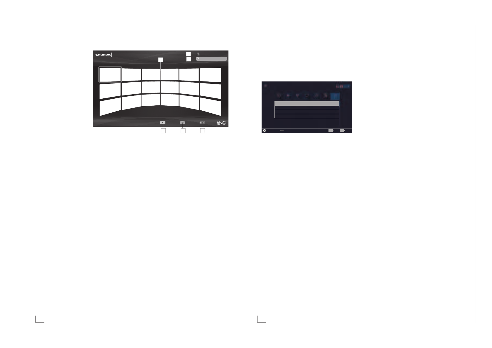
SMART INTER@CTIVE TV 4.0 FEATURE
Chassis G5GRUNDIG Service
1 - 38
--------------------------------
PARENTAL SETTINGS
---------------------------------------------------------------------------------
Smart Inter@ctive TV
4.0 browser main
My Apps
menu
1 Applications.
2 Push button to the
Application s
tore.
3 Search bar.
4 Categories menu.
5 Tools menu.
6 Exit.
Navigation in the main menu
1 Press »y« (red) button in »My apps« menu
and select categories with »
2 Select the required application with »
»
Λ
«, »<« or »>« and press »OK« to
confirm.
– Main menu of the application will be
displayed after a short while.
3 Usage of application mostly depends on
application’
s own structure. Follow the notes
on the screen.
« or »>«.
<
V
2
1
Catagories Tools Exit
4 5 6
3
Playback and other options in
the applications
Note:
7
«,
Some applications do not support all playing options, and playing options may vary
among different applications.
1 »
8« starts playing in the applications;
!« pauses playing in the applications;
2 »
7« stops playing in the applications;
3 »
4 In the applications, press »
start picture search.
5 In the applications, press »
skip forward/backward.
V
«, »Λ«, »<«, »>« allows sliding of the
6 »
navigation keys in the applications and
virtual keyboard.
7 Press »OK« to confirm the selections in
vir
tual keyboard and applications.
8 »1…0« »y« (red), »yy« (green), »
(y
ellow), »
v
arious functions in applications.
« (blue) selects/activates
yyyy
9 »@« switches off the application and goes
back to »My apps« menu.
10 »EXIT« switches off the application and
goes back to t
he last broadcast source you
were in.
Online Store
3
« or »4« to
5« or »6« to
«
yyy
1 Open menu with »MENU« button.
V
2 Select menu item »Settings« with »
»
« or »>« and press »OK« to confirm.
<
3 Select the menu item »Parental« with »
»
« and press »OK« to confirm.
<
– »Parental« menu is displayed.
Settings > Parental
Picture
Parental Guidance Off
Menu Lock Off
Keypad Lock Off
Change PIN
Change Area Change Mode ExitBack
Source TimerSoiund NetworkTV Parental
«, »Λ«,
Tuesday
xx xxx xxxx
BACK EXIT
>
« or
Note:
7
Additional operations are explained in the
following sections.
Parental Guidance
There are movies with content or scenes which
are not suitable for children.
Certain programmes contain information which
identifies such content or scenes and have been
given an access level from 4 to 18. You can select one of the access levels and thus authorise
the playback.
1 From the »Parental« menu use »
to select the line »Parental Guidance« and
press »
« or »>« to confirm.
<
2 Enter the PIN code »1234« with »1...0« in
t
he password prompt.
3 Select the access level with »
4 Press »BACK <« to go back one menu
le
vel or press »EXIT« to end the setting.
V
« or »>«.
<
« or »Λ«
Note:
7
When the TV is in review buffer mode, the
parental rating of the program in the live
broadcast is applied on the content being
watched (rather than the actual parental
rating of the content being watched). As
a result, a parental rated content being
watched in the review buffer mode will not
necessarily show as parental rated and
vice versa. This means that if parental rated
program starts in live broadcast the PIN-pop
up message will appear in review buffer, or
the PIN-pop up message will be dismissed in
review buffer as soon as a program without
parental rating starts in live broadcast.”
Locking the menus
By using this function, you can lock »Automatic
Channel Search«, »Manual Channel Search«
and »Channel Editor« menus as to be accessed
only when the PIN code is entered.
V
1 From the »Parental« menu use »
to select the line »Menu Lock« and press
»
« or »>« to confirm.
<
2 Enter the PIN code »1234« with »1...0« in
t
he password prompt.
3 Activate the lock with »
<
Note:
7
To switch off the menu lock, use »<« or »>«
to select the setting (»Off«).
4 Press »BACK <« to go back one menu
vel or press »EXIT« to end the setting.
le
« or »Λ«
« or »>« (»On«).
62
ENGLISH
70
ENGLISH
Page 39

PARENTAL SETTINGS
Chassis G5GRUNDIG Service
1 - 39
---------------------------------------------------------------------------------
PARENTAL SETTINGS
---------------------------------------------------------------------------------
Blocking the multifunction
switch
When the key lock is activated, the multi function
switch on the television does not function.
V
1 From the »Parental« menu use »
to select the line »Keypad Lock« and press
»
« or »>« to confirm.
<
2 Enter the PIN code »1234« with »1...0« in
he password prompt.
t
3 Activate (On) or deactivate (Off) the panel
lock wit
4 Press »BACK <« to go back one menu
le
vel or press »EXIT« to end the setting.
h »
« or »>«.
<
« or »Λ«
Changing the PIN code
Instead of the default code »1234«, you can
enter a personal code.
Please take note of your personal code.
1 From the »Parental« menu use »
to select the line »Change PIN« and press
»OK« to confirm.
2 Enter the current PIN code »1234« with
»1...0«.
3 Enter your new four-digit personal PIN code
h »1...0«.
wit
4 Reenter your personal PIN code with
»1...0«.
5 Press »BACK <« to go back one menu
le
vel or press »EXIT« to end the setting.
V
« or »Λ«
Blocking a television channel
You can block individual television channels
which are not suitable for children using a
personal PIN code.
1 Open menu with »MENU« button.
V
«.
yyy
«, »Λ«,
« or
>
V
«
V
« (yel-
yyy
V
« or
« (yellow),
V
2 Select menu item »Settings« with »
»
« or »>« and press »OK« to confirm.
<
3 Select the menu item »Source« with »
»
« and press »OK« to confirm.
<
4 Select the line »Channel Editor« with »
or »
Λ
« and press »OK« to confirm.
5 Select the channel to be blocked with »
»
Λ
«, »<« or »>« and highlight with »OK«.
–Channel is marked with »«.
6 Activade the »Tools« menu with »
lo
w).
7 Select the line »Channel Lock« with »
»
Λ
« and press »OK« to confirm.
8 Enter the PIN code »1234« with »1...0« in
t
he password prompt.
9 Confirm the entry with »OK«.
–Channel is marked with »
Note:
7
To remove the lock, select the channel
again with »
vade the »Tools« menu with »
select t
or »
10 Press »EXIT« to end the setting.
V
«, »Λ«, »<« or »>«, acti-
he line »Unlock Channel« with »
Λ
« and press »OK« to confirm
Watching a blocked television
channel
You can watch a TV channel blocked with PIN
code by selecting the TV channel and entering
the PIN code.
1 Select the blocked channel with »1…0« or
»P+«, »P–«.
2 Enter the PIN code »1234« with »1...0« in
t
he password prompt.
– Blocked channel can be viewed.
Note:
7
«,
Channel will be blocked again when you
change the channel.
Resetting PIN code
Use this function if you forget the PIN code.
V
1 From the »Parental« menu use »
to select the line »Change PIN« and press
»OK« to confirm.
2 Enter the PIN code »2 3 5 6« with »1...0«.
3 Enter your new four-digit personal PIN code
h »1...0«.
wit
4 Reenter your personal PIN code with
»1...0«.
5 Press »BACK <« to go back one menu
le
vel or press »EXIT« to end the setting.
«
« or »Λ«
ENGLISH
71
72
ENGLISH
Page 40

SOFTWARE OF THE DEVICE
Chassis G5GRUNDIG Service
1 - 40
---------------------------------------------------------------
ACCESSORIES
------------------------------------------------------------------------------------------------------
1 Open menu with »MENU« button.
V
>
V
« or »Λ«
«, »Λ«,
« or »<«
2 Select menu item »Settings« with »
»
« or »>« and press »OK« to confirm.
<
3 Select the menu item »TV « with »
and press »OK« to confirm.
4 Select the line »About« with »
and press »OK« to confirm.
Settings > TV > Advanced
Picture
Product Info
TV Name Smart Inter@ctive 4...
Software Updates
Restore Factory Defaults
Reset Chanel History
Country Other
Change Area Select ExitBack
Source TimerSound NetworkTV Parental
Tuesday
xx xxx xxxx
BACK EXIT
Note:
7
Additional operations are explained in the
following sections.
Product information
1 From the »About« menu use »V« or »Λ«
to select the line »Product Info« and press
»OK« to confirm.
– Software version information of the pro-
duct is displayed.
2 Press »BACK <« to go back one menu
le
vel or press »EXIT« to end the setting.
Software update (OAD)
(only for digital television channels)
V
1 From the »About« menu use »
to select the line »Software Updates« and
press »OK« to confirm.
2 Select the option »OAD« with »
and press »OK« to confirm.
– The search for new software is being car-
ried out.
Note:
7
If no new software is available the menu
automatically switches off.
3 If new software is available, press »yy«
een) to install the software.
(gr
– The new software will be loaded.
« or »Λ«
V
« or »Λ«
Warning:
7
Television will restart after update. Do
not turn your television’s power off during
updates.
Note:
7
For automatic checking of software update,
select from »Source« menu ° »Advanced«
he line »OAD« with »
t
or »
« to select »On«.
>
V
« or »Λ«. Use »<«
Software update (Internet)
(only for digital television channels)
V
1 From the »About« menu use »
« or »Λ«
to select the line »Software Updates« and
press »OK« to confirm.
V
2 Select the option »Internet« with »
»
Λ
« and press »OK« to confirm.
« or
– The search for new software is being car-
ried out.
Note:
7
If no new software is available the menu
automatically switches off.
3 If new software is available, press »yy«
een) to install the software.
(gr
– The new software will be loaded.
Warning:
7
Television will restart after update. Do
not turn your television’s power off during
updates.
Software update (USB)
1 Plug the memory stick in one of the USB
sockets at the side of the television.
V
2 From the »About« menu use »
to select the line »Software Updates« and
press »OK« to confirm.
3 Select the option »USB« with »
and press »OK« to confirm.
– The software on the USB memory stick is
installed.
« or »Λ«
V
« or »Λ«
You can connect various accessories to your
television to use with video talk, volume control,
motion control or a keyboard and mouse to use
in your web browser. Display the status of the
connected accessory from this menu to perform
various adjustments.
1 Open menu with »MENU« button.
V
>
V
« or »Λ«
«, »Λ«,
« or »<«
V
« or
2 Select menu item »Settings« with »
»
« or »>« and press »OK« to confirm.
<
3 Select the menu item »TV « with »
and press »
V
« to confirm.
4 Select the line »Accessories« with »
»
Λ
« and press »OK« to confirm.
5 Select the needful line with »
and press »OK« to confirm.
Select the needful function with »
« or »>«.
<
6 Press »BACK <« to go back one menu
le
vel or press »EXIT« to end the setting.
Notes:
7
Accessories are sold individually. They
are not provided with your TV. Please
contact your dealer from where you have
purchased your TV in order to obtain more
information about purchasing.
7
The displays for the status and the settings
depend on the accessories used.
74
ENGLISH
ENGLISH
75
Page 41
RESET FUNCTIONS
Chassis G5GRUNDIG Service
1 - 41
----------------------------------------------------------------------------------------
NETWORK SETUP
-------------------------------------------------------------------------------------------
1 Open menu with »MENU« button.
V
« or »<«
>
V
« or »Λ«
«, »Λ«,
2 Select menu item »Settings« with »
»
« or »>« and press »OK« to confirm.
<
3 Select the menu item »TV« with »
and press »OK« to confirm.
4 Select the line »About« with »
and press »OK« to confirm.
Settings > TV > About
Picture
Product Info
TV Name Smart Inter@ctive 4...
Software Updates
Restore Factory Defaults
Reset Chanel History
Country Other
Change Area Select ExitBack
Source TimerSound NetworkTV Parental
Tuesday
xx xxx xxxx
BACK EXIT
Note:
7
Additional operations are explained in the
following sections.
Resetting the television to its
original state
This function enables you to delete the station
lists and all custom settings.
V
1 From the »About« menu use »
to select the line »Restore Factory Defaults«
and press »OK« to confirm.
– Warning screen will be displayed.
Note:
7
If the loaded applications are also to be
deleted, select the line »Save installed
applications« by pressing »
the small tick with »OK«.
2 Select push button »Yes« with »
confirm the security query;
or
select push button »No« with »
cancel deletion process.
– In a short while »Installation Guide« is
displayed.
3 Continue the settings as described in the
chapter on f
irst installation and searching
for channels on page 20.
« or »Λ«
Λ
« and remove
« or »>« to
<
« or »>« to
<
Deleting channel history
This function allows you to delete channel history stored in the Main menu.
V
1 From the »About« menu use »
select the line »Reset Channel History« and
press »OK« to confirm.
– Warning screen will be displayed.
2 Select push button »Yes« with »
confirm the security query;
or
select push button »No« with »
to cancel the function.
3 Press »BACK <« to go back one menu
le
vel or press »EXIT« to end the setting.
« or »Λ« to
« or »>« to
<
« or »>« to
<
Wired network settings
There are two ways of making the wired network settings.
A Automatic connection,
All data regarding connection settings (»IP
Address«, »Netmask«, »Gateway« and
»DNS«) are obtained from modem automatically.
B Manual connection,
all data regarding connection settings (»IP
Address«, »Netmask«, »Gateway« and
»DNS«) must be configured manually.
Automatic connection
Most of the home networks are Dynamic. If
you have a dynamic network, you must use a
DSL modem that supports DHCP. Modems and
IP sharers that support DHCP obtain the »IP
Address«, »Netmask«, »Gateway« and »DNS«
values required for internet access automatically, and thus you are not required to enter those
values manually.
1 Open the menu with »MENU«.
V
2 Select menu item »Settings« with »
»
« or »>« and press »OK« to confirm.
<
3 Select the menu item »Network« with »
»
« and press »V« to confirm.
<
– »Network« menu is active.
Settings > Network
Picture
Change Connection Type Wired
Network Configuration AUTO
Wake-on-LAN Off
Advanced
Source TimerSound NetworkTV Parental
Change AreaConnect Test Connection Select Zurück
4 Select the line »Change Connection Type«
»
V
« or »Λ« and press »OK« to confirm.
5 Select the option »Wired« with »
and press »OK« to confirm.
«, »Λ«,
Tuesday
xx xxx xxxx
V
« or »Λ«
>
BACK
« or
6 Select the line »Network Configuration«
with »
V
« or »Λ« and use »<« or »>« to
select »AUTO«.
7 With »y« (red) select »Connect« to establish
modem connection.
– »Connecting ... Please wait« message
will be displayed, and if the connection
is established »Connection To Gateway:
Success« message will be displayed.
8 Press »yy« (green) to check the performed
settings and also if the local network and
internet connection has been established.
– »Testing ... Please wait« message will
be displayed, and if the connection is
established »Connection To Gateway:
Success«, »Internet Connection: Success«
message will be displayed.
9 Press »EXIT« to end the settings.
Note:
7
If you do not have a dynamic network,
follow the instructions in manual connection
section.
76
ENGLISH
ENGLISH
87
Page 42
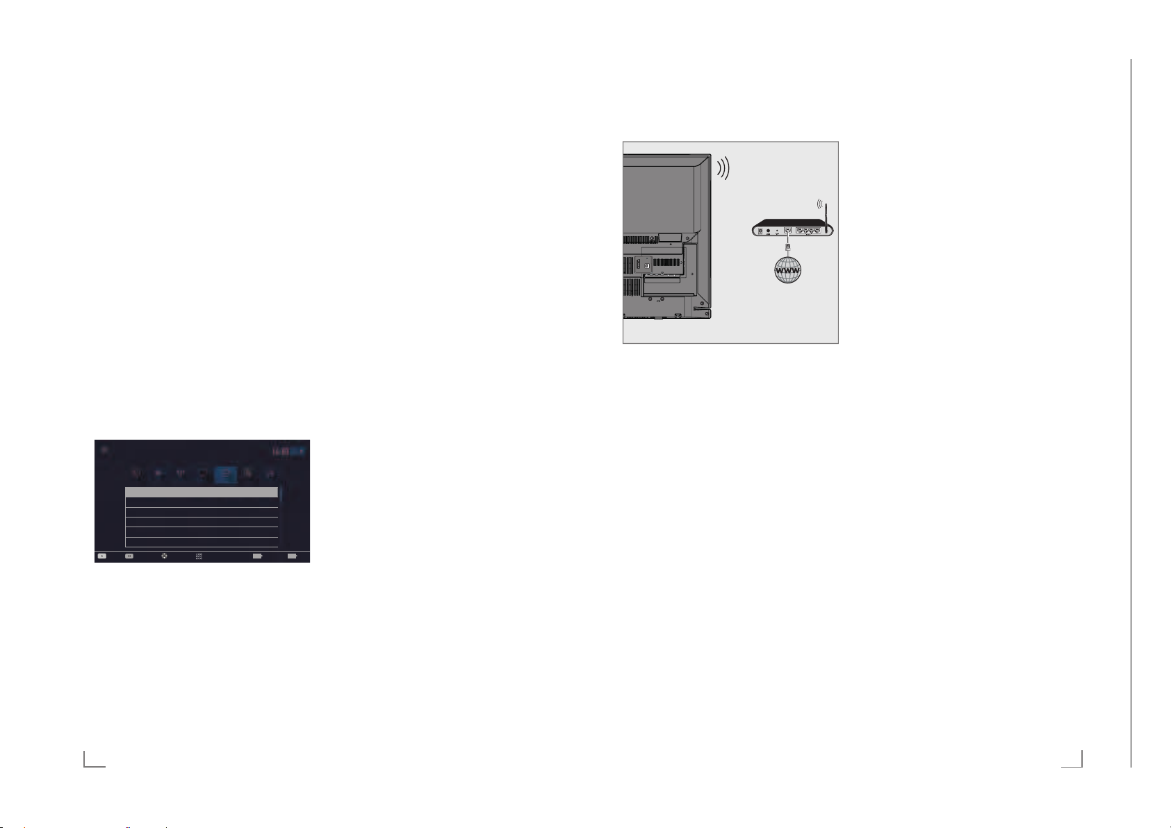
NETWORK SETUP
Chassis J5GRUNDIG Service
1 - 42
Chassis G5GRUNDIG Service
1 - 42
-------------------------------------------------------------------------------------------
NETWORK SETUP
-------------------------------------------------------------------------------------------
Manual connection
Certain networks require Static IP address. If
your network requires a Static IP address, you
must enter the »IP Address«, »Netmask«, »Gateway« and »DNS« values manually. You can
get »IP Adress«, »Netmask«, »Gateway« and
»DNS« values (IPS) from your Internet Service
Provider.
1 Open the menu with »MENU«.
V
2 Select menu item »Settings« with »
»
« or »>« and press »OK« to confirm.
<
«, »Λ«,
3 Select the menu item »Network« with »
»
« and press »V« to confirm.
<
– »Network« menu is active.
4 Select the line »Change Connection Type«
V
« or »Λ« and press »OK« to confirm.
»
V
5 Select the option »Wired« with »
« or »Λ«
and press »OK« to confirm.
6 Select the line »Network Configuration«
V
« or »Λ« sand use »<« or »>« to
wit
h »
select »Manual«.
– »IP Address«, »DNS«, »Netmask« and
»Gateway« options are active.
Settings > Network
Picture
Change Connection Type Wired
Network Configuration Manual
Wake-on-LAN Off
IP Address 192 . 168 . 000 . 200
DNS 192 . 168 . 000 . 254
Netmask 255 . 255 . 255 . 200
Source TimerSound NetworkTV
Change AreaConnect Test Connection
Input Mode
xx xxx xxxx
Tuesday
7 Select the line »IP Address« with »V«.
Enter IP address with »1…0«.
V
8 Select the line »DNS« with »
«.
Enter IP address with »1…0«.
V
9 Select the line »Netmask« with »
«
Enter Netmask address with »1…0«.
V
10 Select the line »Gateway« with »
«.
Enter Gateway address with »1…0«.
88
ENGLISH
>
11 With »y« (red) select »Connect« option to
tablish modem connection.
es
– »Connecting... Please wait« message will
be displayed, and if the connection is
successful, Connection to Gateway: Successful« message will be displayed.
12 Press »yy« (green) to check the performed
settings and also if the local network and
internet connection has been established.
– »Testing ... Please wait« message will
be displayed, and if the connection is
established »Connection To Gateway:
« or
Success«, »Internet Connection: Successful« message will be displayed.
13 Press »EXIT« to end the settings.
ExitBack
EXITBACK
Wireless network
Wireless network connection
SERVICE
AV / S-VHS/COMPONENT
LAN
Optic Out USB(HDD)
HDMI3(ARC) HDMI2
SATELLITE
ANT-IN
13/18V
5V
max. 500mA
max. 50mA
1 Television includes a built-in Wireless WiFi
Adapter to connect it to wireless network.
Notes:
7
Wireless LAN adapter supports IEEE
802.11B/G and N communication
protocols. We recommend you to use IEEE
802.11N protocol to obtain the best performance in wireless HD video playback.
7
If you use a modem that supports IEEE
802.11B/G, video playback performance may
be poor when compared to a modem that supports IEEE 802.11N since the data transfer rate
of IEEE 802.11B/G protocol is lower.
7
Please note that video playback performance in a DLNA application on a wireless
local network and in a SMART inter@
ctive TV 4.0 application on a network with
internet connection depends on the number
of users on the network as it is the case in
every wireless network.
7
It is recommended to switch off the equipment that are not in use in home network in
order to avoid unnecessary network traffic.
7
Placing the modem or wireless network
sharer on an elevated location will increase
the wireless connection reception strength.
7
Wireless connection reception strength may vary
depending on the type of the modem and the
distance between the modem and television.
Wireless network settings
You have several ways to connect your TV to
your home network.
A Automatic connection,
all data regarding connection settings (»IP
Address«, »Netmask«, »Gateway« and
»DNS«) are obtained from modem auto-
matically.
Depending on the router, you can use the
following options:
– Option “WPS-PBC” (Push Button Configu-
ration);
– Connecting with a WPS PIN;
– Connecting by entering the network pass-
word.
B Manual connection,
all data regarding connection settings (»IP
Address«, »Netmask«, »Gateway« and
»DNS«) must be configured manually.
ENGLISH
89
Page 43
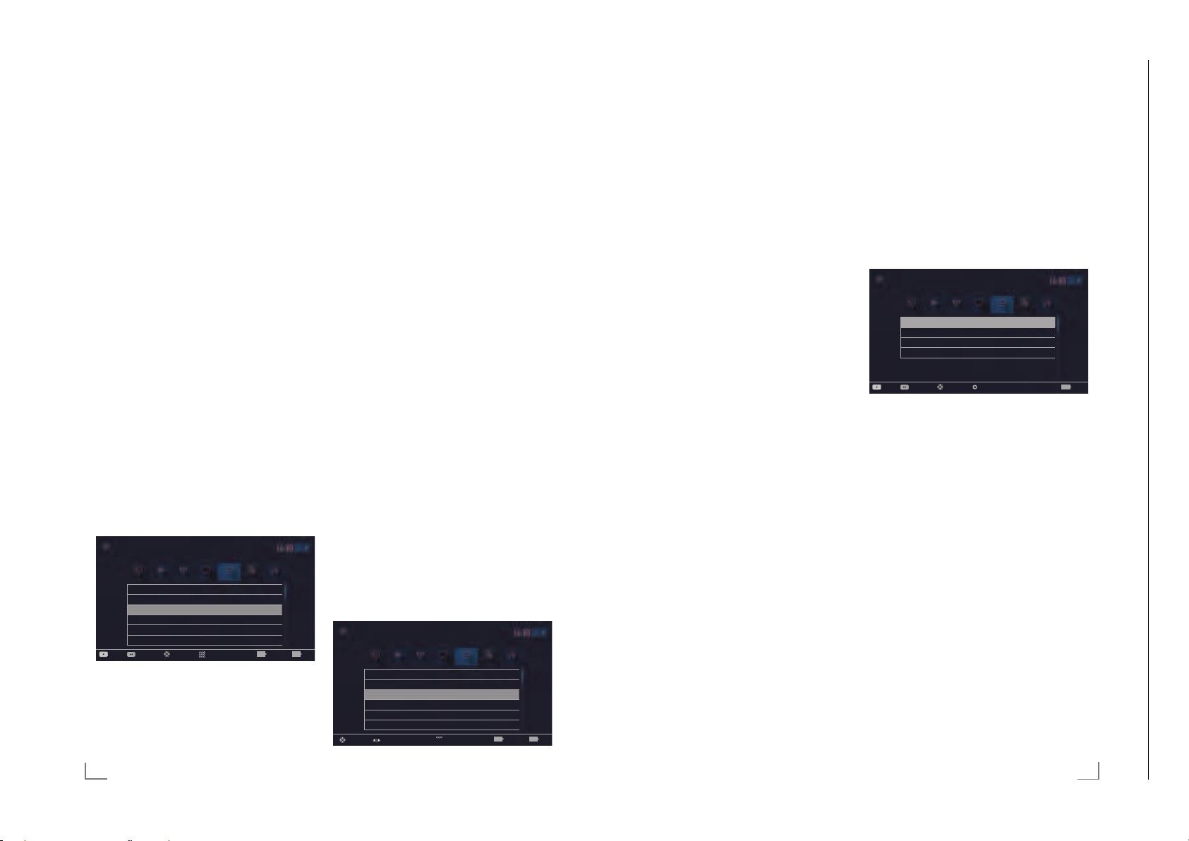
NETWORK SETUP
Chassis J5GRUNDIG Service
1 - 43
Chassis G5GRUNDIG Service
1 - 43
-------------------------------------------------------------------------------------------
NETWORK SETUP
-------------------------------------------------------------------------------------------
Technical requirements
Most of the home networks are Dynamic. If
you have a dynamic network, you must use a
DSL modem that supports DHCP. Modems and
IP sharers that support DHCP obtain the »IP
Address«, »Netmask«, »Gateway« and »DNS«
values required for internet access automatically, and thus you are not required to enter those
values manually.
Wireless WPS network connection
through by pressing a button
1 Open the menu with »MENU«.
V
2 Select menu item »Settings« with »
»
« or »>« and press »OK« to confirm.
<
3 Select the menu item »Network« with »
»
« and press »V« to confirm.
<
– »Network« menu is active.
«, »Λ«,
« or
>
4 Select the line »Change Connection Type«
V
« or »Λ« and press »OK« to
h »
wit
confirm.
5 Select the option »Wireless WPS« with »
or »
Λ
« and press »OK« to confirm.
V
– WiFi warning message will be displayed.
6 Confirm the message »Do you want to turn
on Wi-F
i?« select »Yes« with »
press »OK« to confirm.
7 Select the line »WPS Type« with »
»
Λ
« and select the option »Push Button«
with »
« or »>«.
<
Settings > Network
Picture
Çhange Connection Type Wireless WPS
WiFi On
WPS Type Push Button
Select Access Point N/A
Network Configuration Auto
Wake-on-LAN Off
Source TimerSound NetworkTV Parental
Change AreaConnect Test Connection
Input Mode
« or »>« and
<
V
« or
Tuesday
xx xxx xxxx
ExitBack
EXITBACK
8 With »y« (red) select »Connect« to establish
modem connection.
– »Push the WPS button on your Access
Point« message is displayed.
9 Press the WPS button on the router.
10 To continue after pressing the WPS button
he access point, select the option »Con-
on t
tinue« with »
confirm.
« or »> «and press »OK« to
<
– The “Connection to Gateway: Success”
message will be displayed.
11 Press »yy« (green) to make sure that the
netw
ork connection is established with the
current settings.
– »Testing ... Please wait« message will
be displayed, and if the connection is
established »Connection To Gateway:
Success«, »Internet Connection: Success«
messages will be displayed.
12 Press »EXIT« to end the setting.
Wireless WPS network connection with
PIN
1 Open the menu with »MENU«.
2 Select menu item »Settings« with »
»
« or »>« and press »OK« to confirm.
<
3 Select the menu item »Network« with »
«
»
« and press »V« to confirm.
<
– »Network« menu is active.
4 Select the line »Change Connection Type«
V
« or »Λ« and press »OK« to
wit
h »
confirm.
5 Select the option »Wireless WPS« with »
or »
« and press »OK« to confirm.
>
– WiFi warning screen will be displayed.
6 Confirm the message »Do you want to turn
i?« select »Yes« with »
on Wi-F
press »OK« to confirm.
<
7 Select the line »WPS Type« with »
»
Λ
« and select the option »PIN« with »<«
or »
«.
>
Settings > Network
Picture
Çhange Connection Type Wireless WPS
WiFi On
WPS Type PIN
Select Access Point N/A
Network Configuration Auto
Wake-on-LAN Off
Change Area
Source TimerSound NetworkTV Parental
Change Mode
V
«, »Λ«,
« or
>
«
<
« or »>« and
V
« or
Tuesday
xx xxx xxxx
ExitBack
EXITBACK
8 Select the line »Select Access Point« with
»
V
« or »Λ« and press »OK« to confirm.
– Present WPS-supported wireless networks
are scanned to display in the »Select Access Point« menu.
9 Select the network that you want to connect
V
« or, »Λ« and press »OK« to
h »
wit
confirm.
– 8-digit pin code is displayed in the wire-
less WPS menu.
Note:
7
Refer to the manual of your router to find
out how the PIN is entered via a PC.
10 Use a PC to enter the pin on the router (e.g.
A
VM FRITZ!Box: menu item WLAN Set-
tings... WPS) and save.
Note:
7
The 8-digit PIN code must be entered in the
modem interface in 2 minutes; otherwise,
connection of television with the modem is
cut.
11 Press »yy« (green) to confirm the registra-
tion.
– The message “Connection to Gateway:
Success” appears.
12 Press »yy« (green) to check the performed
settings and also if t
he local network and
internet connection has been established.
– »Testing ... Please wait« message will
be displayed, and if the connection is
established »Connection To Gateway:
Successfull«, »Internet Connection: Successfull« messages and MAC address will
be displayed.
13 Press »EXIT« to end the setting.
Connecting automatically by entering
the network password
Use this method for establishing a connection
if your router does not support “WPS-PBC” or
WPS PIN entry.
1 Open the menu with »MENU«.
V
xx xxx xxxx
Tuesday
«, »Λ«,
« or
>
BACK
2 Select menu item »Settings« with »
»
« or »>« and press »OK« to confirm.
<
3 Select the menu item »Network« with »
»
« and press »V« to confirm.
<
– »Network« menu is active.
Settings > Network
Picture
Change Connection Type Wired
Network Configuration AUTO
Wake-on-LAN Off
Advanced
Source TimerSound NetworkTV Parental
Change AreaConnec Test Connection Select Back
4 Select the line »Change Connection Type«
with »
V
« or »Λ« and press »OK« to
confirm.
V
5 Select the option »Wireless« with »
»
Λ
« and press »OK« to confirm.
« or
– WiFi warning message will be displayed.
6 Confirm the message »Do you want to turn
i?« select »Yes« with »
on Wi-F
press »OK« to confirm.
« or »>« and
<
7 Select the line »Network Configuration«
V
« or »Λ« and select the option
wit
h »
»AUTO« with »
« or »>«.
<
8 Select the line »Select Access Point« with
V
« or »Λ« and press »OK« to confirm.
»
– »Select Access Point« menu is displayed
by scanning available wireless networks.
9 Select the network that you want to con-
V
« or »Λ« and press »OK« to
h »
nect wit
confirm.
– Wireless connection password screen is
displayed.
90
ENGLISH
ENGLISH
91
Page 44
NETWORK SETUP
Chassis J5GRUNDIG Service
1 - 44
Chassis G5GRUNDIG Service
1 - 44
-------------------------------------------------------------------------------------------
NETWORK SETUP
-------------------------------------------------------------------------------------------
Note:
7
For device to discover the wireless modem
on the network, the network name should
support ASCII characters.
V
10 Select the required character with »
»
Λ
«, »<« or »>« and move to the next
«,
character with »OK«.
– Using »Shift« ° »OK«, you can switch
betw
een uppercase letters / numbers and
lowercase letters / special characters.
– Select »Del« to delete the character
ed and press »OK« to confirm.
enter
11 Confirm the password with »yy« (green).
– »Connecting ... Please wait« message
will be displayed, and if the connection
is established »Connection To Gateway:
Success« messages will be displayed.
12 Press »yy« (green) to check the performed
settings and also if t
he local network and
internet connection has been established.
– »Testing ... Please wait« message will
be displayed, and if the connection is
established »Connection To Gateway:
Success«, »Internet Connection: Success«
messages will be displayed.
13 Press »EXIT« to end the setting.
Note:
7
If you do not have a dynamic network,
follow the instructions in manual connection
section.
Manual connection
Certain networks require Static IP address. If
your network requires a Static IP address, you
must enter the »IP Address«, »Netmask«, »Gateway« and »DNS« values manually. You can
get »IP Address«, »Netmask«, »Gateway« and
»DNS« values (IPS) from your Internet Service
Provider.
1 Open the menu with »MENU«.
V
2 Select menu item »Settings« with »
»
« or »>« and press »OK« to confirm.
<
3 Select the menu item »Network« with »
»
« and press »V« to confirm.
<
– »Network« menu is active.
«, »Λ«,
« or
>
4 Select the line »Change Connection Type«
V
« or »Λ« and press »OK« to
wit
h »
confirm.
5 Select the option »Wireless« with »
»
« and press »OK« to confirm.
>
– WiFi warning screen will be displayed.
<
« or
6 Confirm the message »Do you want to turn
on Wi-F
i?« select »Yes« with »
press »OK« to confirm.
« or »>« and
<
7 Select the line »Network Configuration«
V
« or »Λ« and select the option
wit
h »
»Manual« with »
– »IP Address«, »DNS«, »Netmask« and
« or »>«.
<
»Gateway« options are active.
Settings > Network
Picture
Change Connection Type Wired
WiFi On
Select Access Point N/A
Network Configuration Manual
Wake-on-LAN Off
IP Address 192 . 168 . 000 . 200
Source TimerSound NetworkTV
Change AreaConnect Test Connection
Input Mode
xx xxx xxxx
Tuesday
EXITBACK
8 Select the line »IP Address« with »V«.
Enter IP address with »1…0«.
V
9 Select the line »DNS« with »
«.
Enter DNS address with »1…0«.
V
10 Select the line »Netmask« with »
«.
Enter Netmask address with »1…0«.
11 Select the line »Gateway« with »V«.
Enter Gateway address with »1…0«.
12 Select the line »Select Access Point« with
Λ
« or »V« and press »OK« to confirm.
»
– »Select Access Point« menu is displayed
by scanning available wireless networks.
13 Select the network that you want to connect
V
« or »Λ« and confirm with »OK«.
h »
wit
– Wireless connection password screen is
displayed.
Note:
7
For device to discover the wireless modem
on the network, the network name should
support ASCII characters.
V
14 Select the required character with »
»
Λ
«, »<« or »>« and move to the next
«,
character with »OK«.
– Using »Shift« ° »OK«, you can switch
betw
een uppercase letters / numbers and
lowercase letters / special characters.
– Select »Del« to delete the character
enter
ed and press »OK« to confirm.
15 Confirm the password with »yy« (green).
– »Connecting ... Please wait« message
will be displayed, and if the connection
is established »Connection To Gateway:
Success« messages will be displayed.
16 Press »yy« (green) to check the performed
settings and also if t
he local network and
Change TV Name
To make it possible to identify your TV in the network, the name “Inter@ctive TV 4.0” is assigned
at the factory. You can change the name.
1 Open the menu with »MENU«.
V
V
V
« or »Λ«
V
«, »Λ«,
« or »Λ«
« or
V
«,
2 Select menu item »Settings« with »
»
« or »>« and press »OK« to confirm.
<
3 Select the menu item »TV« with »
and press »
V
« to confirm.
– »TV« menu is active.
4 Select the line »About« with »
and press »OK« to confirm.
5 Select the line »TV Name« with »
»
Λ
« and press »OK« to confirm
6 Delete the current name step-by-step with
»y« (red).
7 Select the required character with »
»
Λ
«, »<« or »>« and move to the next
character with »OK«.
– Using »Shift« ° »OK«, you can switch
betw
een uppercase letters / numbers and
lowercase letters / special characters.
– Select »Del« to delete the character
ed and press »OK« to confirm.
enter
8 Confirm the new name by pressing »yy«
(gr
een).
9 Press »EXIT« to end the setting.
internet connection has been established.
– »Testing ... Please wait« message will
be displayed, and if the connection is
established »Connection To Gateway:
Success«, »Internet Connection: Success«
messages will be displayed.
17 Press »EXIT« to end the setting.
ExitBack
92
ENGLISH
ENGLISH
93
Page 45

Chassis G5GRUNDIG Service
1 - 45
NETWORK SETUP
-------------------------------------------------------------------------------------------
Connecting the TV to a “hidden”
network
Even if the SSID (Service Set Identifier) of the
router is not visible, you can connect your TV to
this network.
1 Open the menu with »MENU«.
V
2 Select menu item »Settings« with »
»
« or »>« and press »OK« to confrim.
<
3 Select the menu item »Network« with »
»
« and press »V« to confirm.
<
– »Network« menu is active.
4 Select the line »Select Access Point« with
V
« or »Λ« and press »OK« to confirm.
»
– »Select Access Point« menu appears and
available wireless networks are scanned
and displayed in the menu.
5 Press »y« (red).
– »Add Network« menu appears.
6 Select the line »Access Point Name« with
V
« or »Λ« and press »OK« to confirm.
»
– A menu for entering the SSID will be
displayed.
Note:
7
For device to discover the wireless modem
on the network, the network name should
support ASCII characters.
7 Select the required character with »
»
Λ
«, »<« or »>« and move to the next
character with »OK«.
– Using »Shift« ° »OK«, you can switch
betw
een uppercase letters / numbers and
lowercase letters / special characters.
– Select »Del« to delete the character
8 Confirm the SSID by pressing »yy« (green).
9 Select the line »Security Type« with »
10 Confirm the setting with »y« (red).
ed and press »OK« to confirm.
enter
»
Λ
« and select the required option (WPA2)
with »
« or »>«.
<
– The network is now in the »Select Access
Point« menu.
«, »Λ«,
>
V
«,
V
« or
« or
V
11 Select the network with »
press »OK« to confirm.
– Wireless connection password screen is
displayed.
12 Select the required character with »
»
Λ
«, »<« or »>« and move to the next
character with »OK«.
– Using »Shift« ° »OK«, you can switch
betw
een uppercase letters / numbers and
lowercase letters / special characters.
– Select »Del« to delete the character
enter
ed and press »OK« to confirm.
13 Confirm the password by pressing »yy«
een).
(gr
– »Connecting ... Please wait« message will
be displayed.
14 Press »yy« (green) to make sure that the
netw
ork connection is established with the
current settings.
– »Testing ... Please wait« message will
be displayed, and if the connection is
established »Connection To Gateway:
Success«, »Internet Connection: Success«
messages and MAC address will be
displayed.
15 Press »EXIT« to end the setting.
« or »Λ« and
V
«,
SETTING FURTHER CHANNELS
Creating a list of favourites - analog
channels
You can select your favourite channels and save
them in up to four lists (FAV1 to FAV4).
1 In the »Channel Editor« menu, select the
channel(s) y
ites list with »
highlight the television channel by pressing
»OK«.
–Channel is marked with »«.
2 Activade the »Tools« menu with »
lo
w).
3 Select the line »Add To Fav.« with »
»
Λ
–»Add to Fav.« menu is displayed.
4 Select the favorite list you want to add the
selected channels wit
store with »OK«.
– The channels are marked in the Channel
Editor with »«, »«, »« or »«.
– You can add the same channel in more
than one favourites list.
– Each favourite list can contain maximum
255 channels.
Notes:
7
You can delete channels from the favourites list. Press »
fav
»
Λ
channel(s) you want to delete with »
»
Λ
by pressing »OK«.
ess »
Pr
»R
emove from Fav.« with »
confirm with »OK«. The channel you have
selected is no
list.
7
When a channel stored in the favourite
channel list is deleted channel order in the
favourite list is updated.
5 Press »EXIT« to close the menu.
ou want to add in the favor-
V
«, »Λ«, »<« or »>«, and
« (yel-
yyy
V
« and press »OK« to confirm.
V
« or »Λ« and
h »
« (yellow), select the
orites list the channel is in with »
« and press »OK« to confirm. Select the
«, »<« or »>«, and highlight the channel
yyy
« (yellow) and select the line
yyy
w deleted from the favorites
V
« or
V
« or
V
«,
« or »Λ« and
Displaying signal information
(only for digital television channels)
1 Open the menu with »MENU«.
2 Select menu item »Settings« with »
»
« or »>« and press »OK« to confirm.
<
3 Select the menu item »Source« with »
»
« and press »V« to confirm.
<
– »Source« menu is active.
4 Select the line »Advanced« with »
»
Λ
« and press »OK« to confirm.
5 Select the line »Signal Information« with
V
« or »Λ« and press »OK« to confirm.
»
– »Signal Information« menu is displayed.
Notes:
7
Signal information changes depending on
the current source.
7
Signal information is shown at the top of the
menu. The more »Frequency« and »Signal
Strength« bar stretches to the right, the more
signal you have.
7
The signal level not only depends on your
receiver system, but also on the channel
which is currently active. Remember this
when aligning your antenna using the
signal level display.
6 Press »EXIT« to close the menu.
-----------------------------------------------------
V
«, »Λ«,
« or
>
V
« or
94
ENGLISH
108
ENGLISH
Page 46
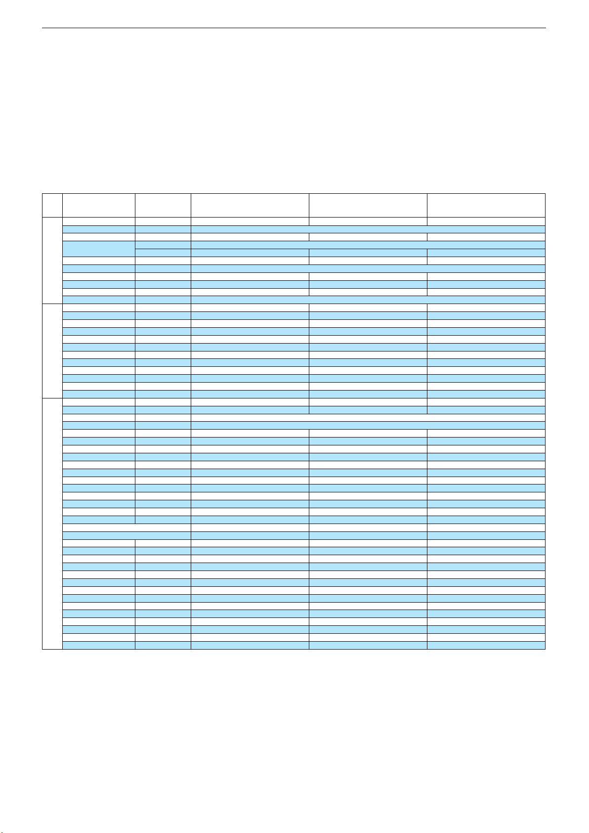
32 VLE 5620 BN
43 VLE 5620 BN
49 VLE 5620 BN
System Configuration
TV Mode
HDCP Verify
Customer/Factory
Debug Mode
Plug Play
On/OffOnHotel
Off
On/Off
CI Key Verify
Panel Energy Class
A…D, Default
Recovery Mode
AC Direct On
On/Off
On/Off
Source Configuration
Code 2356
Miracast TX HDCP Verify
ATV
Avail/Navail
Air
Cable
Avail/Navail
Avail/Navail
Satellite
USB
Avail/Navail
Avail/Navail
HDMI1
HDMI2
Avail/Navail
Avail/Navail
HDMI3
HDMI4
Avail/Navail
Avail/Navail
AV1 (Scart)
Component (Scart)
Avail/Navail
Avail/Navail
TV Configuration
Code 2356
S-VHS (Scart)
OSD Selection
Avail/Navail
Grundig
GRFSet1/USB Recording
Remote Control
On/Off
Operator Selection
Keypad
3 Button + 1 STD
7 Segment Display
CEC
On/Off
On/Off
Speaker Output Power
Subwoofer Output Power
3…15W@6/8/16
Ω
10/15W@8/16Ω, Off
Hidev Mono
Optic Out
On/Off
On/Off
Sports Mode
EPG Padding Time
On/Off
On/Off
BISS Key
Voice Recognition RC
On/Off
On/Off
HbbTV
Power LED Brightness Low
On/Off
Power LED Brightness High
Language Selection
0…255
Jitter Immunity
Uart Enable
On/Off
On/Off
Screen Capture
DTS Cert Mode
On/Off
On/Off
Bluetooth
Weather Widget
On/Off
On/Off
Bubble Help
Multi Source Fav. List
On/Off
On/Off
KocSistem Mode
Custom Boot/Screen Saver
On/Off
On/Off
Basic Mode
Settings Recovery
On/Off
On/Off
SnapNstore Extended
On/Off
Menü
Menu
3333 44
44
Menüpunkt
Point of Menu
OK
Einstellung
Adjustment
1111 22
22
Customer
prüft HDCP im EEPROM / verifies HDCP in EEPROM
Customer
Customer
Off
ATS Reset: Netz ein –> Automatischer Sendersuchlauf / Power on –> automatic programme search
OffXOffXOff
OffXOff
prüft CI Key / verifies CI Key
Class A
Class A+
On
OffOnOff
Class A+
On
Off
prüft Miracast TX HDCP im EEPROM / verifies Miracast TX HDCP in EEPROM
Avail
Avail
Avail
Avail
Avail
Avail
Avail
Avail
Avail
Avail
Avail
Avail
Avail
Avail
Avail
Avail
Avail
Avail
Avail
Avail
Avail
Avail
Navail
Avail
Navail
Avail
Avail
Avail
Avail
Avail
Navail
Avail
Avail
Avail
Grundig
Avail
Grundig
On
Fernbedienung wählen / Select used remote control
On
Avail
Grundig
On
Erforderliche Betreiber auswählen / Select required Operator
3 Button + 1 STD
3 Button + 1 STD
OffOnOff
On
3 Button + 1 STD
Off
On
15W @16ohm
Off
10W @8ohm
Off
OffOnOff
On
10W @8ohm
Off
OffOnOffOnOff
On
OnOnOn
On
Off
On
OnOnOff8Off8230230Off823
0
Off
Off
Off
Off
On
OffOnOff
Off
Off
On
Off
OffOnOffOnOnOnOnOnOffOnOnOnOffOnOffOnOnOnOnOnOffOnOn
OnOnOn
On
Chassis G5GRUNDIG Service
1 - 46
Alle weiteren Menüs werden über die Gerätesoftware programmiert und dürfen nicht verstellt werden.
All other menus are programmed by the software of the set and must not be adjusted.
Service- und Sonderfunktionen
Tastenfunktionen
MENU
Aufrufen/Beenden des Menüs / Beenden des Service Modes
3333 4444Menü-Zeile (Menüpunkt) wählen
OK
Aufrufen der Menüs
1111 2222Wert ändern
@@@@Untermenü: Zurück zum Hauptmenü
Service-Mode aktivieren
– Taste
MENU
drücken, dann Zahlenfolge 8500 eingeben.
Service-Mode beenden
– Taste
MENU
drücken.
1. Grundeinstellwerte
Service and Special Functions
Functions of the buttons
MENU
Call up/exit the Menu / exit the Service Mode
3333 4444Call up the dialogue line (point of menu)
OK
Call up the Menus
1111 2222 Changing the settings
@@@@Submenu: Back to main menu
Calling up the Service Mode
– Press button
MENU
, than enter the code number 8500.
Exit the Service Mode
– Press button
MENU
.
1. Basic Settings
2. Software-Versionsnummer
Die Software-Versionsnummer wird unten im Menü Einstellungen
und im Service Menü angezeigt. z.B.: G7GRMR.-.-.-.-.V02.03.01
2. Software Version Number
The software version number is shown on the lower part of the options menu and the service menu. e.g.: G7GRMR.-.-.-.-.V02.03.01
Page 47

GRUNDIG Service Chassis G5
Platinenabbildungen und Schaltpläne / Layout of PCBs and Circuit Diagrams
Chassisplatte / Chassis Board ZG7190R-2
T: Bestückungsseite / Component Side
B: Lötseite / Solder Side
POS. X Y POS. X Y POS. X Y POS. X Y POS. X Y POS. X Y POS. X Y POS. X Y
C100 T 136 22
C101 T 134 22
C102 T 14 43
C103 T 116 73
C200 T 134 19
C201 T 136 19
C202 T 157 50
C203 T 155 50
C204 T 138 53
C205 T 143 54
C206 T 152 40
C207 T 87 59
C208 T 85 58
C209 T 85 57
C210 T 82 55
C300 B 117 61
C301 T 91 61
C302 B 119 58
C303 B 119 57
C304 T 98 62
C305 B 132 56
C306 B 119 55
C307 B 121 56
C308 T 153 52
C309 T 153 65
C310 B 125 52
C311 T 134 29
C312 T 131 44
C313 T 130 45
C314 B 127 49
C315 B 131 58
C316 B 132 60
C317 B 127 53
C318 T 100 61
C319 B 125 46
C320 B 128 44
C321 B 122 48
C322 B 120 53
C323 T 119 69
C325 B 123 53
C326 T 145 63
C327 T 145 66
C328 B 123 55
C329 B 122 52
C330 T 101 67
C331 T 139 43
C332 T 139 41
C333 T 134 33
C334 T 134 36
C335 T 119 71
C336 T 120 71
C337 T 122 70
C338 T 134 37
C339 T 140 43
C340 T 143 63
C341 T 143 66
C342 T 132 31
C400 T 69 24
C401 T 69 26
C402 T 68 26
C403 T 68 24
C404 T 17 21
C405 T 69 19
C406 T 73 16
C407 T 180 28
C408 T 180 32
C409 T 13 28
C410 T 17 19
C500 T 124 98
C501 T 107 81
C502 T 112 77
C503 T 145 76
C504 T 148 70
C505 T 143 44
C506 T 146 47
C507 T 144 47
C508 T 145 47
C509 T 143 47
C510 T 152 45
C600 T 68 48
C601 T 68 50
C602 T 37 32
C603 T 41 30
C604 T 50 10
C605 T 50 12
C606 T 37 30
C607 T 39 25
C608 T 39 23
C609 T 39 21
C610 T 39 16
C611 T 37 19
C612 T 44 13
C613 T 44 15
C614 T 37 14
C615 T 37 12
C616 T 43 15
C617 T 43 13
C618 T 43 25
C619 T 48 21
C620 T 48 32
C621 T 139 45
C622 T 57 13
C623 T 53 13
C624 T 43 29
C625 T 140 46
C626 T 43 23
C627 T 43 30
C628 T 45 32
C629 T 46 21
C630 T 43 32
C631 T 139 47
C632 T 138 46
C700 T 168 19
C701 T 168 18
C702 T 168 20
C703 T 175 24
C704 T 176 24
C705 T 177 24
C706 T 168 15
C707 T 168 16
C708 T 171 24
C709 T 172 11
C710 T 171 15
C711 T 172 15
C712 T 173 23
C713 T 171 23
C714 T 173 24
C715 T 168 12
C716 T 178 21
C717 T 174 10
C718 T 175 10
C719 T 177 8
C720 T 178 4
C721 T 178 17
C722 T 178 18
C723 T 163 15
C724 T 163 13
C725 T 151 13
C726 T 147 13
C727 T 145 13
C728 T 150 13
C729 T 148 13
C730 T 155 20
C731 T 154 16
C732 T 154 19
C733 T 155 38
C734 T 155 40
C735 T 161 23
C736 T 162 36
C737 T 161 39
C738 T 145 21
C739 T 145 16
C740 T 163 23
C741 T 155 21
C742 T 165 37
C743 T 155 35
C744 T 151 23
C745 T 151 22
C746 T 150 23
C747 T 147 23
C748 T 145 22
C749 T 158 12
C750 T 157 12
C751 T 149 22
C800 T 46 53
C801 T 47 53
C802 T 32 58
C803 T 43 52
C804 T 41 54
C805 T 37 55
C806 T 48 55
C807 T 44 54
C808 T 49 53
C809 T 10 54
C810 T 28 64
C811 T 18 59
C812 T 20 59
C813 T 16 59
C814 T 51 56
C815 T 50 58
C816 T 33 63
C817 T 50 62
C818 T 16 65
C819 T 51 61
C820 T 33 67
C821 T 20 65
C822 T 18 65
C823 T 34 72
C824 T 28 65
C825 T 12 69
C826 T 40 53
C827 T 37 70
C828 T 50 68
C832 T 69 67
C833 T 66 67
C834 T 66 72
C835 T 69 72
C836 T 39 69
C837 T 48 68
C838 T 29 72
C839 T 41 69
C840 T 182 14
C841 T 182 18
C843 T 62 69
C844 T 44 69
C845 T 43 69
C846 T 47 69
C847 T 45 71
C848 T 57 37
C849 T 58 35
C850 T 54 35
C851 T 53 35
C852 T 59 37
C853 T 55 35
C854 T 60 35
C855 T 48 35
C856 T 45 39
C857 T 66 37
C858 T 64 36
C859 T 38 42
C860 T 45 49
C861 T 48 42
C862 T 40 42
C863 T 42 42
C864 T 65 40
C865 T 64 42
C866 T 49 45
C867 T 44 42
C868 T 48 49
C869 T 48 39
C870 T 48 50
C875 T 72 44
C876 T 69 39
C877 T 69 44
C878 T 72 39
C879 T 52 50
C880 T 52 52
C881 T 54 50
C900 T 72 108
C901 T 69 112
C902 T 74 79
C903 T 71 77
C904 T 77 48
C905 T 58 95
C906 T 77 100
C907 T 55 96
C908 T 83 46
C909 T 54 102
C910 T 76 56
C911 T 79 56
C912 T 83 48
C913 T 64 101
C914 T 61 100
C915 T 66 95
C916 T 82 76
C917 T 85 74
C918 T 91 63
C919 T 93 68
C920 T 85 75
C921 T 105 99
C922 T 97 98
C923 T 74 65
C924 T 149 66
C925 T 97 95
C926 T 109 95
C927 T 96 74
C928 T 143 33
C929 T 93 97
C930 T 112 97
C931 T 91 97
C932 T 112 99
C933 T 112 95
C934 T 104 88
C935 T 105 88
C936 T 102 87
C937 T 73 63
C938 T 145 26
C939 T 79 64
C940 T 144 33
C942 T 78 100
C943 T 81 101
C944 T 82 101
C945 T 84 101
C946 T 74 52
C1000 T 101 31
C1001 T 90 40
C1002 T 89 41
C1003 T 93 50
C1004 T 91 49
C1005 B 98 35
C1006 B 96 39
C1007 B 89 34
C1008 B 94 38
C1009 T 86 42
C1010 T 93 44
C1011 T 91 23
C1012 T 89 44
C1013 T 95 44
C1014 B 99 38
C1015 T 90 46
C1016 T 96 23
C1017 T 99 31
C1018 T 104 36
C1019 T 90 46
C1020 T 101 33
C1021 B 95 33
C1022 T 100 26
C1023 T 88 47
C1024 T 89 48
C1025 T 86 25
C1026 T 87 23
C1100 T 117 12
C1101 T 179 46
C1102 T 180 49
C1103 T 181 68
C1104 T 179 51
C1105 T 112 24
C1106 T 169 48
C1200 T 16 35
C1201 T 185 73
C1202 T 188 73
C1203 T 88 94
C1204 T 15 32
C1205 T 16 34
C1206 T 16 37
C1300 T 154 105
C1301 T 128 107
C1302 T 128 106
C1400 T 57 72
C1401 T 53 82
C1402 T 50 82
C1403 T 40 73
C1404 T 55 73
C1405 T 26 80
C1406 T 42 108
C1407 T 37 73
C1408 T 25 90
C1409 T 19 101
C1410 T 18 96
C1411 T 50 96
C1412 T 28 98
C1413 T 37 75
C1414 T 43 108
C1415 T 53 75
C1416 T 45 103
C1417 T 43 103
C1418 T 47 108
C1419 T 39 75
C1420 T 46 108
C1421 T 38 73
C1423 T 44 108
C1424 T 42 105
C1425 T 39 103
C1426 T 65 81
D400 T 17 12
D401 T 90 10
D402 T 179 37
D600 T 67 50
D601 T 67 48
D700 T 175 7
D701 T 156 32
D702 T 156 29
D703 T 161 25
D704 T 154 12
D800 T 61 71
D900 T 75 97
D901 T 74 100
D902 T 66 102
D903 T 71 57
D904 T 65 106
D905 T 63 106
D906 T 62 106
D907 T 60 106
D908 T 59 106
D1100 T 176 51
D1200 T 88 97
D1201 T 184 73
D1202 T 14 34
D1203 T 84 89
D1204 T 83 89
D1205 T 82 91
D1206 T 86 91
IC100 T 122 53
IC101 T 137 26
IC102 T 117 75
IC103 T 18 43
IC200 T 153 43
IC400 T 73 19
IC401 T 177 29
IC402 T 17 25
IC500 T 111 80
IC501 T 125 100
IC600 T 47 27
IC700 T 173 19
IC701 T 178 7
IC702 T 150 18
IC703 T 163 31
IC800 T 43 62
IC801 T 58 66
IC802 T 56 43
IC900 T 77 75
IC901 T 78 52
IC902 T 58 98
IC903 T 79 69
IC904 T 103 93
IC905 T 77 63
IC906 T 145 30
IC1000 T 94 35
IC1100 T 120 14
IC1101 T 176 48
IC1102 T 180 54
IC1103 T 111 21
IC1104 T 166 50
IC1105 T 166 47
IC1106 T 166 44
IC1200 T 85 95
IC1300 T 141 106
IC1400 T 39 89
IC1401 T 63 77
IC1402 T 63 77
L200 T 158 50
L300 T 154 52
L301 T 147 64
L302 T 146 64
L303 T 140 39
L304 T 140 41
L305 T 142 42
L306 T 134 32
L307 T 134 34
L308 T 87 52
L400 T 17 28
L401 T 69 16
L402 T 183 24
L500 T 107 83
L600 T 59 13
L700 T 169 15
L701 T 170 15
L702 T 174 15
L703 T 172 10
L704 T 170 12
L705 T 175 15
L706 T 178 19
L707 T 178 16
L708 T 161 13
L709 T 144 13
L710 T 155 17
L711 T 156 26
L712 T 158 40
L713 T 155 14
L714 T 156 20
L800 T 16 54
L801 T 24 60
L802 T 25 70
L803 T 17 71
L804 T 74 73
L805 T 40 36
L806 T 40 47
L807 T 75 43
L900 T 73 105
L901 T 108 106
L902 T 72 55
L903 T 66 99
L904 T 83 51
L905 T 63 96
L906 T 102 99
L907 T 100 99
L908 T 88 68
L909 T 96 92
L910 T 111 104
L911 T 111 90
L913 T 145 28
L914 T 101 101
L915 T 108 102
L1000 T 90 52
L1100 T 181 45
L1200 T 15 33
L1300 T 156 105
L1400 T 53 80
L1401 T 55 71
L1402 T 29 78
L1403 T 42 110
L1404 T 17 101
L1405 T 18 97
L1406 T 50 97
L1407 T 28 99
L1408 T 18 99
L1409 T 43 110
L1410 T 47 111
L1411 T 46 111
L1412 T 52 73
L1413 T 52 72
L1414 T 44 111
R100 T 136 32
R101 T 138 32
R102 T 28 96
R103 T 28 97
R104 T 137 31
R105 T 134 26
R106 T 134 24
R107 T 36 103
R108 T 37 103
R109 T 18 76
R110 T 44 90
R111 T 38 95
R112 T 16 77
R113 T 41 97
R114 T 104 64
R115 T 22 76
R116 T 16 78
R117 T 21 76
R118 T 40 81
R119 T 38 83
R120 T 44 87
R121 T 17 85
R122 T 17 86
R123 T 26 82
R124 T 22 84
R125 T 25 82
R126 T 17 93
R127 T 17 94
R128 T 122 31
R129 T 18 78
R130 T 108 64
R131 T 108 62
R132 T 117 30
R133 T 119 30
R134 T 16 75
R135 T 105 64
R136 T 119 28
R200 T 135 19
R201 T 129 46
R202 T 132 42
R203 T 142 53
R204 T 138 55
R205 T 133 40
R206 T 88 58
R207 T 84 55
R208 T 92 57
R209 B 82 61
R210 B 99 73
R211 B 87 66
R212 B 86 58
R213 B 83 65
R214 B 95 73
R215 B 96 73
R216 B 87 62
R217 B 98 73
R218 B 82 63
R219 T 92 58
R220 T 92 59
R301 T 99 62
R302 T 99 66
R303 T 135 47
R400 T 18 9
R401 T 16 9
R402 T 14 25
R403 T 14 24
R404 T 69 13
R405 T 68 13
R406 T 92 10
R407 T 92 9
R408 T 179 40
R409 T 178 40
R500 T 128 100
R501 T 114 77
R502 T 113 83
R503 T 155 76
R504 T 158 76
R505 T 110 83
R506 T 111 83
R507 T 149 77
R508 T 154 103
R509 T 145 75
R510 T 154 109
R511 T 148 71
R512 T 151 52
R513 T 151 54
R514 T 139 76
R515 T 136 76
R516 T 151 76
R517 T 154 74
R518 T 162 76
R519 T 150 47
R520 T 152 47
R521 T 158 75
R522 T 165 76
R523 T 171 76
R524 T 168 76
R525 T 147 76
R526 T 143 46
R527 T 142 46
R528 T 127 75
R529 T 142 76
R530 T 130 75
R531 T 134 76
R532 T 149 47
R533 T 148 47
R534 T 124 108
R535 T 125 105
R601 T 71 49
R602 T 39 32
R603 T 38 32
R604 T 39 30
R605 T 48 10
R606 T 38 30
R607 T 48 12
R608 T 38 28
R609 T 38 25
R610 T 37 28
R611 T 38 23
R612 T 38 21
R613 T 38 19
R614 T 38 16
R615 T 37 16
R616 T 37 21
R617 T 37 25
R618 T 39 19
R619 T 39 13
R620 T 41 15
R621 T 41 13
R622 T 46 32
R623 T 47 21
R624 T 55 13
R625 T 43 27
R626 T 49 21
R627 T 43 20
R628 T 54 13
R629 T 49 32
R700 T 172 13
R701 T 178 22
R702 T 176 15
R703 T 178 12
R704 T 145 15
R705 T 155 22
R706 T 168 32
R707 T 147 26
R708 T 148 23
R709 T 162 21
R710 T 163 21
R711 T 163 19
R712 T 168 29
R713 T 168 34
R714 T 168 35
R715 T 162 19
R800 T 46 51
R801 T 48 53
R802 T 50 59
R803 T 53 67
R804 T 34 58
R805 T 50 63
R806 T 30 64
R807 T 30 67
R808 T 31 72
R809 T 50 65
R810 T 45 37
R811 T 182 15
R812 T 51 68
R813 T 183 18
R814 T 183 14
R815 T 182 19
R816 T 63 67
R817 T 46 47
R818 T 60 69
R820 T 62 65
R821 T 57 69
R823 T 61 65
R824 T 48 70
R825 T 47 71
R826 T 45 69
R827 T 57 35
R828 T 59 35
R829 T 64 37
R830 T 54 58
R831 T 64 43
R836 T 64 46
R837 T 48 71
R900 T 70 109
R901 T 72 97
R902 T 70 105
R903 T 71 100
2 - 1
Page 48

GRUNDIG Service Chassis G5
POS. X Y POS. X Y POS. X Y POS. X Y POS. X Y POS. X Y POS. X Y POS. X Y
R904 T 70 100
R905 T 76 100
R906 T 79 100
R907 T 53 105
R908 T 86 101
R909 T 57 108
R910 T 74 53
R911 T 55 95
R912 T 79 49
R913 T 54 100
R914 T 81 46
R915 T 54 99
R916 T 83 45
R917 T 53 101
R918 T 81 98
R919 T 73 66
R920 T 73 67
R921 T 72 66
R922 T 56 105
R923 T 99 89
R924 T 100 89
R925 T 112 86
R926 T 98 89
R927 T 110 86
R928 T 108 86
R929 T 77 98
R930 T 77 97
R931 T 74 55
R932 T 57 107
R933 T 109 97
R934 T 109 98
R935 T 78 73
R936 T 80 73
R937 T 59 103
R1000 T 98 25
R1001 T 96 46
R1002 T 98 28
R1003 T 94 46
R1004 T 98 44
R1005 T 95 26
R1006 T 101 46
R1007 T 93 24
R1008 T 99 48
R1009 T 88 39
R1010 T 100 43
R1011 T 90 26
R1012 T 103 44
R1013 T 85 30
R1014 T 102 40
R1015 T 87 28
R1016 T 100 29
R1017 T 102 28
R1018 T 105 42
R1019 T 96 28
R1020 T 83 32
R1021 T 106 37
R1022 T 84 27
R1023 T 107 40
R1024 T 86 37
R1025 T 104 39
R1026 T 82 29
R1027 T 105 33
R1028 T 84 35
R1029 T 97 30
R1030 T 81 28
R1031 T 88 43
R1032 T 88 42
R1033 T 89 23
R1034 T 86 25
R1035 T 93 47
R1100 T 125 16
R1101 T 124 16
R1102 T 123 16
R1103 T 117 14
R1104 T 182 55
R1105 T 181 66
R1106 T 181 70
R1107 T 176 45
R1108 T 174 47
R1109 T 183 53
R1110 T 177 54
R1111 T 115 12
R1112 T 105 18
R1113 T 104 17
R1114 T 114 7
R1115 T 103 15
R1116 T 126 22
R1117 T 126 20
R1118 T 115 22
R1119 T 169 50
R1120 T 169 49
R1121 T 168 51
R1122 T 162 50
R1123 T 168 47
R1124 T 168 45
R1125 T 161 46
R1126 T 169 43
R1127 T 183 55
R1200 T 188 96
R1201 T 16 36
R1202 T 188 85
R1203 T 186 73
R1204 T 14 42
R1205 T 16 38
R1206 T 13 41
R1207 T 188 75
R1208 T 183 73
R1209 T 90 92
R1210 T 89 92
R1211 T 88 92
R1212 T 81 94
R1213 T 92 92
R1214 T 84 92
R1215 T 79 94
R1300 T 127 103
R1301 T 127 109
R1302 T 154 107
R1303 T 156 107
R1400 T 35 75
R1401 T 48 100
R1402 T 46 103
R1404 T 38 105
R1405 T 40 103
R1406 T 42 75
R1407 T 56 78
R1408 T 56 75
R1409 T 56 77
R1410 T 50 78
S100 T 27 110
S101 T 11 86
S301 T 8 87
S400 T 9 17
S401 T 60 25
S402 T 9 19
S403 T 79 10
S404 T 186 34
S405 T 60 25
S500 T 146 95
S600 T 60 54
S601 T 28 32
S602 T 56 4
S700 T 171 5
S701 T 149 6
S800 T 9 62
S801 T 188 15
S802 T 9 48
S900 T 90 111
S901 T 61 110
S906 T 103 4
S1100 T 128 4
S1101 T 192 59
S1200 T 191 109
S1201 T 191 97
S1202 T 10 36
S1203 T 191 86
S1204 T 191 74
S1206 T 10 35
SH2 T 157 17
SH3 T 142 17
T800 T 55 68
T900 T 69 97
T901 T 72 111
T902 T 70 102
T1100 T 124 13
T1101 T 117 9
T1102 T 114 9
T1103 T 107 18
T1104 T 124 20
T1200 T 15 40
TP1 B 20 104
TP2 B 23 102
TP3 B 21 106
TP4 B 24 96
TP5 B 23 98
TP6 B 24 100
TP7 B 24 104
TP8 B 26 104
TP9 B 25 107
TP10 B 27 102
TP11 B 28 95
TP12 B 26 97
TP13 B 31 97
TP14 B 33 99
TP15 B 31 100
TP16 B 31 103
TP17 B 30 107
TP18 B 32 105
TP19 B 35 99
TP20 B 34 102
TP21 B 33 107
TP22 B 35 103
TP23 B 36 107
TP24 B 38 105
TP25 B 14 76
TP26 B 18 76
TP27 B 16 77
TP28 B 40 78
TP29 B 42 90
TP30 B 9 84
TP31 B 7 86
TP32 B 11 81
TP33 B 15 82
TP34 B 7 93
TP35 B 9 90
TP36 B 9 96
TP37 B 24 80
TP38 B 18 84
TP39 B 18 87
TP40 B 21 85
TP41 B 25 83
TP42 B 14 86
TP43 B 15 88
TP44 B 18 89
TP45 B 24 86
TP46 B 21 88
TP47 B 16 91
TP48 B 13 90
TP49 B 14 92
TP50 B 36 85
TP51 B 25 88
TP52 B 17 93
TP53 B 14 95
TP54 B 68 113
TP55 B 135 48
TP56 B 131 49
TP57 B 152 46
TP58 B 153 43
TP59 B 132 39
TP60 B 100 73
TP61 B 85 65
TP62 B 84 61
TP63 B 86 60
TP64 B 84 63
TP65 B 94 73
TP66 B 97 74
TP67 B 111 57
TP68 B 18 17
TP69 B 61 27
TP70 B 10 18
TP71 B 61 24
TP72 B 10 16
TP73 B 27 20
TP74 B 76 17
TP75 B 77 10
TP76 B 81 10
TP77 B 71 20
TP78 B 177 34
TP79 B 187 32
TP80 B 187 36
TP81 B 122 26
TP82 B 109 79
TP83 B 113 77
TP84 B 124 101
TP85 B 110 83
TP86 B 179 9
TP87 B 164 17
TP88 B 145 14
TP89 B 156 14
TP90 B 18 58
TP91 B 14 63
TP92 B 13 66
TP93 B 17 62
TP94 B 66 69
TP95 B 61 37
TP96 B 189 15
TP97 B 186 19
TP98 B 176 19
TP99 B 36 43
TP100 B 22 60
TP101 B 69 41
TP102 B 83 75
TP103 B 111 104
TP104 B 118 37
TP105 B 100 101
TP106 B 69 69
TP107 B 86 107
TP108 B 69 102
TP109 B 84 107
TP110 B 81 107
TP111 B 79 106
TP112 B 76 106
TP113 B 65 96
TP114 B 85 48
TP116 B 113 89
TP117 B 92 93
TP118 B 72 63
TP119 B 159 21
TP120 B 126 14
TP121 B 135 21
TP122 B 125 17
TP123 B 189 48
TP124 B 126 36
TP125 B 125 11
TP126 B 117 15
TP127 B 120 14
TP128 B 179 45
TP129 B 175 46
TP130 B 180 68
TP131 B 185 54
TP132 B 183 51
TP133 B 150 16
TP134 B 176 54
TP135 B 183 47
TP136 B 186 56
TP137 B 179 54
TP138 B 115 12
TP139 B 98 10
TP140 B 116 23
TP141 B 89 30
TP142 B 101 9
TP143 B 99 7
TP144 B 114 29
TP145 B 110 15
TP146 B 113 18
TP147 B 11 33
TP148 B 17 31
TP149 B 191 74
TP150 B 13 42
TP151 B 81 93
TP152 B 86 98
TP153 B 89 94
TP154 B 80 90
TP155 B 80 88
TP156 B 80 86
TP157 B 80 84
TP158 B 93 108
TP159 B 49 84
TP160 B 45 93
TP161 B 30 88
TP162 B 41 106
TP163 B 47 77
TP164 B 68 94
TP165 B 31 78
TP166 B 47 79
TP167 B 18 96
TP168 B 48 97
TP169 B 28 84
TP170 B 27 87
TP171 B 46 107
TP172 B 47 105
TP173 B 42 102
TP174 B 40 70
TP175 B 44 99
TP176 B 39 72
TP177 B 46 102
TP178 B 44 105
TP179 B 43 75
TP180 B 41 74
TP181 B 42 80
TP182 B 40 80
TP183 B 79 7
TP184 B 63 56
TP185 B 60 54
TP186 B 38 7
TP187 B 28 49
TP188 B 23 47
TP189 B 28 41
TP190 B 23 39
TP191 B 23 32
TP192 B 28 26
TP193 B 23 24
TP194 B 28 22
TP195 B 28 15
TP196 B 52 10
TP197 B 56 8
TP198 B 23 17
TP199 B 23 13
TP200 B 168 44
TP201 B 61 22
TP202 B 60 30
TP203 B 65 30
TP204 B 63 31
TP205 B 11 24
TP206 B 15 22
TP207 B 71 76
TP208 B 192 108
TP209 B 192 97
TP210 B 192 85
TP211 B 9 36
TP212 B 14 37
TP213 B 83 95
TP214 B 84 93
X200 T 140 54
X700 T 168 22
X701 T 145 18
X1400 T 40 105
2 - 2
Page 49
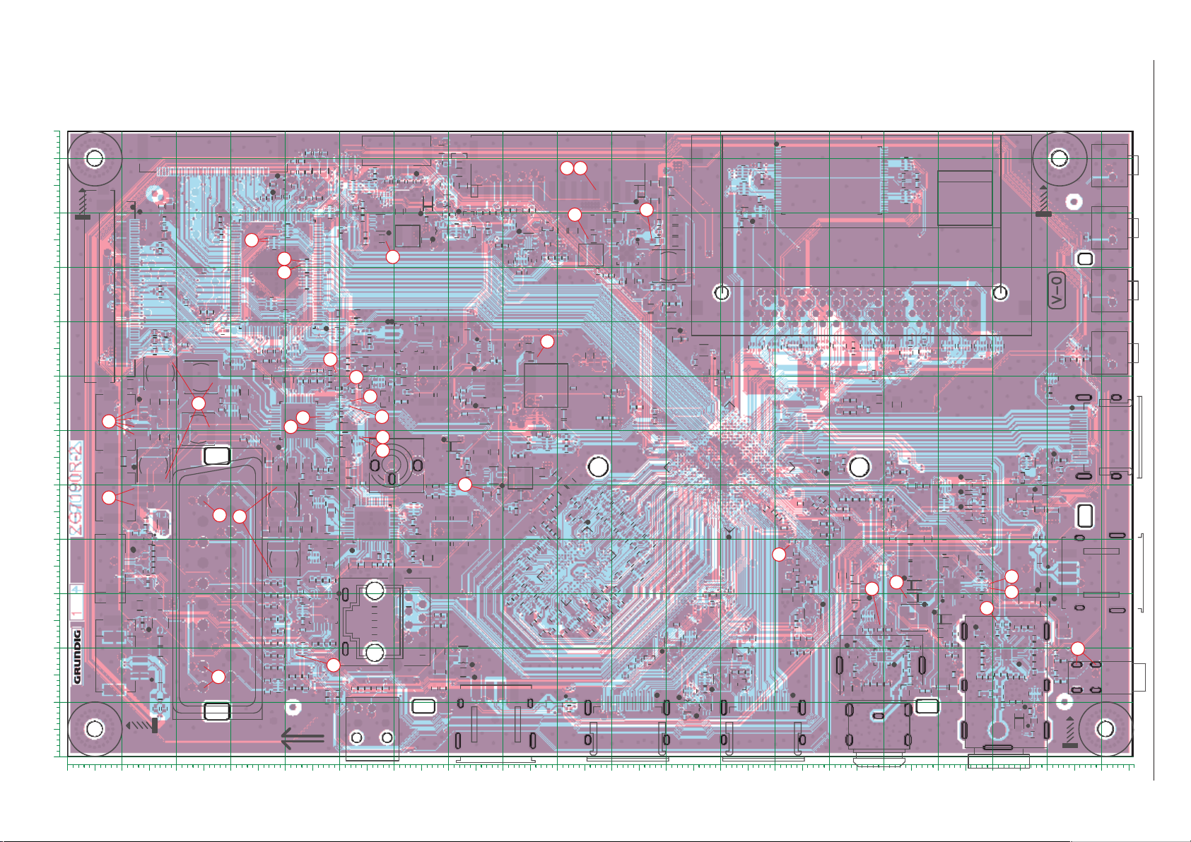
Chassisplatte / Chassis Board ZG7190R-2
100
110
0102030405060708090 100 110 120 130 140 150 160 170 180 190
X
Ansicht von der Bestückungsseite / View of Component Side
GRUNDIG Service Chassis G5
2 - 3
90
LVDS
S301
80
70
60
50
40
30
20
MH1
10
0
Y
MH4
LVDS
S100
41
S101
FID4
1
1
L1408
L1405
C1410
R127
R126
R122
R121
R116
R112
R134
1503
C825
S800
1
26
C813
4
C809
S802
1
L800
26
SUBWOOFER
ZG7190R-2
S1206
KEYPAD
S1202
S402
IC402
3
C102
R1204
R1206
11
L1200
C1204
C409
R402
R403
1
T1200
1
R1205
C1206
R1201
C1200
C1205
D1202
IC103
L400
1
C404
C410
WIFI
4
1
6
S400
D400
R401
TRANSPORT LINE
FID3
1
R1127
19
R813
R814
D1201
28
S1201
R1200R1202R1207
S1204
C1201
R1203
C1202
HEADPHON E
MH2
S1203
S404
S1200
HDMI
USB
S801
S901
L1411
L1410
L1414
L1403
L1409
C1420
1
X1400
R1404
IC1400
L1404
C1409
R129
R109
C818C822
C811
L1407
C1412
R103
R102
C1408
R124
R125
R123
C1405
102
L1402
R115
R117
L802
R808
L803
C821
L801
C812
C838
R807
C824
25
R806
C810
S601
SCART
1
R108
R107
C1425
64
R113
20
R111
18
19
R119
R118
R1400
C1413
C1419
C823
C1421
C1407
C827
C836
36
C820
C816
48
R804
C802
C805
L806
17
25
C606
R610R617C611R616
R615 C602
C614
C615
C859
R602
R618 R604C608C609 C607
R613 R612 R611 R609 R608R606
C610
R614 R603
R619
FID1
1
16
R400
C1418
C1414
C1406
C1423
C1424
R1405
C1417
C1416
R1402
R1401
R110
R120
128
R1406
27
C1403
R837
C847
R825
R824
C839
C846
R826
C845
C844
C837
IC800
22
21
12
1
C806
C804
C807
C826
C862
R801
C801
C800
C803
R800
C870
C860 C868
R817
C861
C863
C867
C869
C856
R810
L805
C630
C620
C628
R622
C627
C603
C624
R625
C618
C626
IC600
C629
R623
R627
15
R620
C616
C617
C612 C613
R621
R607
R605
1
C619
38
C1402
R1410
24
C808
C866
C855
C605
C604
L1406
R629R626
C1411
R809
R805
C817
R802
C815
1
C814
C828
C819
L1412
L1413
R907 R922
C1401
L1400
C1415
8
R803
R812
R830
C880
C879
36
IC802
48
C851
R909
R932
C909
IC902
R917
R913
R915
C907
C905
R911
IC1401
1
R1407
R1409
R1408
C1404
L1401
C1400
R821
T800
9
IC801
10
24
23
C881
SERVICE ONLY
1
C848
R827
C853
S401
R624
C623
C622
R628 C850
D908
R937
1
4
IC1402
1
12
C852
R828
C849
L600
D800
R818
C854
S602
OPTIC
D907
C901
T901
R900R904
1
C900
R902
D904
D905
D906
C913
C914
L905
C1426
C843
R816
R823
R820
R836
24
R831
C865
C864
R829
C858
11
77
L900
14
T902
1
D902
D901
R903
L903
R901
D900 R930
T900
1
C915
C902
C903
L804
C834
C835
1
R920
C833
C832
IC905
R921
R919
C923
1
C937
S600
D903
L902
R931
R910
C946
3
R601
D600
C600C601
D601
C877
C875
C876
C878
C857
2
2
S405
ETHERNET
C402
C401
C400
C403
IC400
C405
C406
8
8
L401
R404
R405
IC900
1
1
C944
C943
R905
C906
C942
R929
R918
1
R1215R906
R1212
IC1200
R1214
D1205
C916
R935
R936
IC903
C939
C910
C911
C210
1
IC901
R912
C912
C904
C908
R916
R914
L807
R1020
R1026
R1030
S403
1
L904
D1204
R1028
C920
C208
C209
R207
R1022
USB
C945
D1203
C917
C1009
R1013
R1034
Tr igger
87
R908
D1200
C931
C1203
R1211
R1209
R1213
R1210
D1206
L914
1
C922
C929
C925
L909
R926
R923
5
L908
C207
R206
L308
C1024
C
1023
C1012
R1031
R1032
R1009
R1024
IC1000
R1015
C1025
R1033
C1026
C927
C919
R1035
R1003
C1010
R1007 R1005
C1013
1
S906
R302
R301
C304
R1008
R1001
R1004
R1010
C1017
R1016
R1019
R1029
R1002
C1022
R1000
C1016
19
C918
C301
R220
R219
R208
C1003
L1000
C1004
C1015
C1019
C1002
C1001
R1011
C1011
1
R406
D401
R407
S900
POWER
L901
L910
1
L915
2
C932
C921
R934
L907
L906
C930
R933
1
C933
C926
IC904
R924
L911
C935
C934
C936
R928R927 R925
R502
R506
R505
L500
C501
1
IC500
C330
R114
R135
R130
R131
C318
R1006
R1012
R1018
R1014
R1023
R1025
R1021
C1018
R1027
C1020
C1000
R1017
T1103
R1112
R1113
R1115
IC1103
1
IC102
R501
C502
C103
C1105
R1118
1
R1103
C1100
R1111
1
T1102
T1101
R1114
HDMI
C323
IC100
R132
R136
IC1100
1
HDMI
1
C335
R133
1
PCMCIA
C336
C337
1
R128
T1104
19
R534
C500
R1102
T1100
R535
IC501
IC1300
1
R528
R1101
R1100
R1301
R1300
R1117R1116
C1301
C1302
R500
1
24
R514
R515
R531
R530
R201
C313
C312
R202
7
C342
R105
R106
R529
R204
C205
X200
C204
1
C631
C625
R303
C621
C632
C331
C339
L305
L304
C332
L303
R205
C338
C334
L307
C333
L306
R101
R100
R104
1
C311
IC101
C101
C100
C201
C200
R200
SH3
1
S1100
48
R1302
C1300
R510
R508
R1303
L1300
BARCODE
B1
MH3
25
S500
R504
L301
C506
R707
R511
C504
14
1
C747
IC702
C726
C924
R533
R532 R507
R708
C746
C751 C745
C729
C728
R503
R517
R705
C741
C730
L300
C734
C733
C743
L710
L713
R518
R521
R1122
L200
C202
C203
R1125
L712
C737
C736
D701
IC703
D702
D703
C735
L714
C732
SH2
C731
C723
L708
C750
C749
R516
C309
C308
R512R513
R519
C510R520
IC200
C206
6
L711
C744
1
C725
D704
1
1
1
IC1105
IC1106
1
R710C740R711
R715R709
C724
IC1104
R522 R524
C742
S700
1
C715L704
R1121
R1119
R1120
C1106
R1123
R1124
R1126
R714
R713
R706
R712
C702
C700
C701
C707
R523
R1208
R1106
C1103
R1105
S1101
IC1102
1
R1110
R1104C841
R1109
C1104
D1100
1
C708
IC700
C710
R700
C709
L703
C1102
R1108
R1107
C1101
L1100
R409
R408
D402
1
12
IC401
1
C408
11
C714
C712
24
C711
L702
C717
1
C407
L402
C705
C703
C704
R701
7
C716
L706
R815
C722
1
C721
L707
R811
R702
L705
C840
R703
C718
C719
FID2
D700
IC701
1
C720
IC1101
13
C713
X700
13
19
L701
L700
C706
C503
R525
R509
C341
C327
L302
C326
R203
C509
C507
C508
R527
R526
C505 C340
C940
C928
IC906
L913
C938
C748
C738
1
X701
C739
R704
L709
C727
S701
Page 50
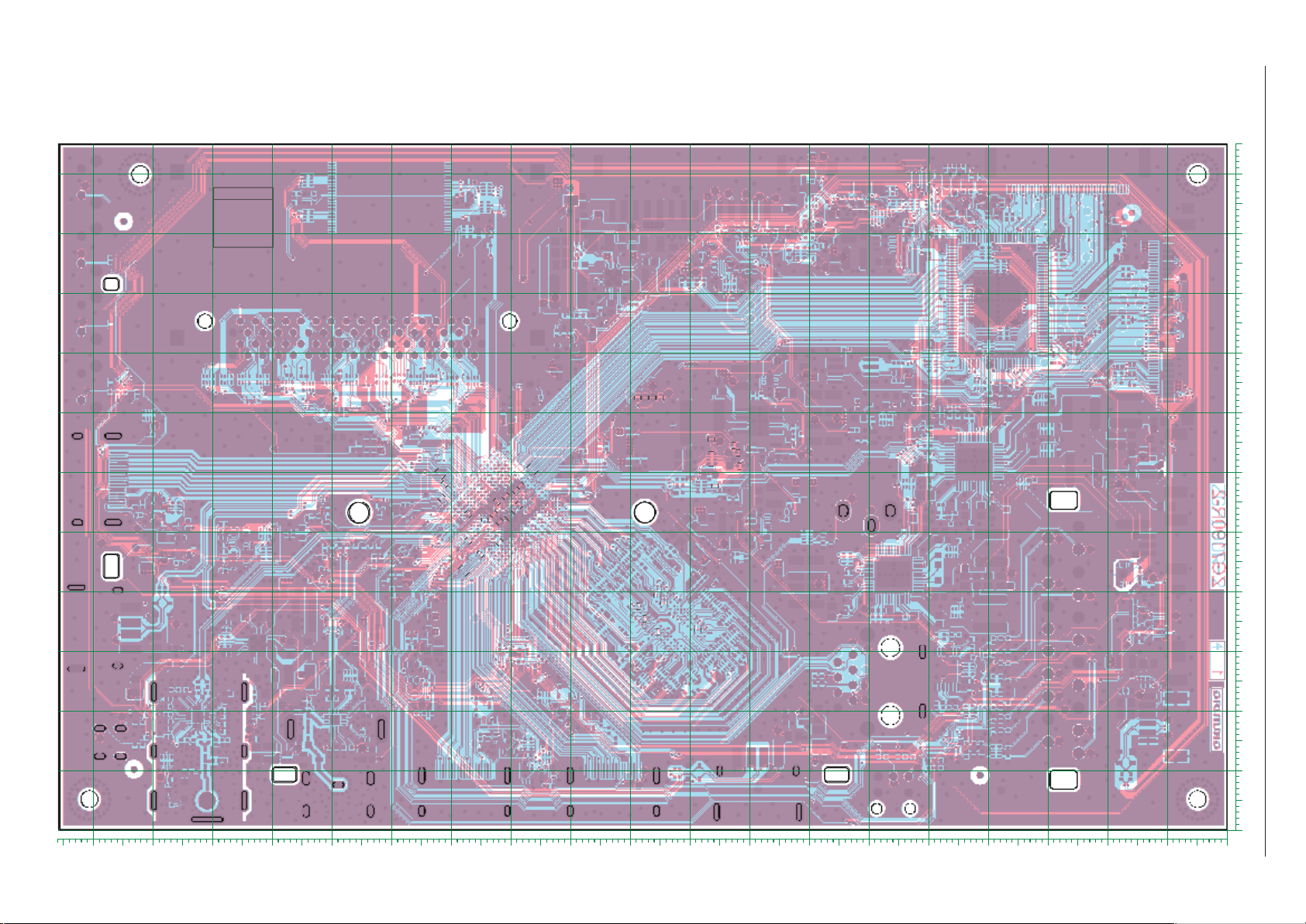
Chassisplatte / Chassis Board ZG7190R-2
100
110
0102030405060708090100110120130140150160170180190
X
Ansicht von der Lötseite / View of Solder Side
BARCODE
B2
TP129
TP200
TP87
2 - 4
TP209
TP210
TP208
TP149
TP123
TP96
TP80
TP79
TP136
TP97
FID7
TP131
TP132
TP135
FID6
TP130
TP137
TP128
TP86
TP134
TP78
TP98
TP119
GRUNDIG Service Chassis G5
TP54
TP158
TP107
TP110
TP109
TP111
TP62
TP213
TP102
TP112
TP108
TP113
TP118
TP164
TP207
TP94
TP106
TP184
TP185
TP101
TP95
TP204
TP202
TP203
TP69
TP71
TP77
TP201
TP197
TP151
TP154
DATA
TP155
CLOCK
TP156
RESET
TP157
VPROG
R213
R218
R209
TP74
TP75
TP76
TP183
TP103
TP84
TP116
TP85
TP82
TP83
C316
C315
C305
C317
TP56
TP55
TP57
TP58
TP121
TP133
TP89
TP88
C314
C319
C320
TP59
TP124
TP122
TP120
TP125
C300
C302
C303
C307
C328
C325
C322
C329
C310
C321
TP81
TP127
C306
TP104
TP126
TP67
TP144
TP140
TP146
TP145
TP138
TP60
TP142
TP105
C1014
TP143
C1005
TP139
TP152
TP153
TP214
TP117
TP66
TP65
R215
R210
R214
R217
TP61
R211
TP64
R216
TP63
R212
TP114
C1006
C1008
C1021
C1007
TP141
TP196
TP159
TP172
TP168
TP171
TP177
TP166
TP163
TP160
TP178
TP175
TP179
FID5
TP162
TP173
TP181
TP180
TP29
TP174
TP182
TP28
TP176
TP186
TP24
TP17
TP23
TP50
TP22
TP21
TP20
TP19
TP14
TP18
TP16
TP15
TP13
TP161
TP165
TP169
TP170
TP9
TP3
TP8
TP7
TP1
TP10
TP2
TP6
TP5
TP12
TP4
TP11
TP51
TP45
TP41
TP37
FID8
TP167
TP52
TP44
TP46
TP39
TP40
TP38
TP26
TP36
TP53
TP49
TP47
TP35
TP48
TP43
TP33
TP27
TP31 TP34
TP42
TP30
TP32
TP25
90
80
70
TP92
TP91
TP93
TP100
TP90
TP187
TP188
TP99
TP189
TP190
TP191
TP192
TP193
TP194
TP73
TP198
TP195
TP199
TP150
TP212
TP211
TP147
TP148
TP205
TP206
TP70
TP68
TP72
60
50
40
30
20
10
0
Y
Page 51
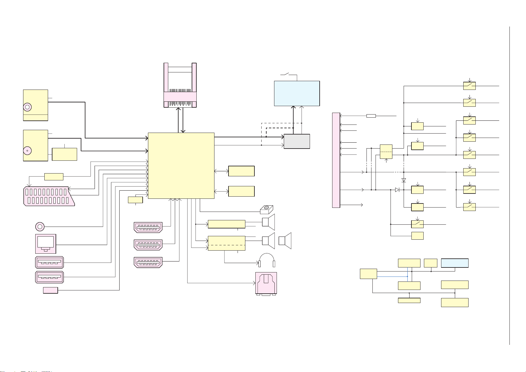
Chassisplatte – Blockschaltplan / Chassis Board – Block Circuit Diagram
GRUNDIG Service Chassis G5
IC700
Tuner
Analog
I2C
DVB-T/T2/C
Si2151
IC702
Tuner SAT1
DVB-S/S2
AV2018
I2C
IC600
2 - 5
Full-Scart, PC-RGB & YPrPb & Audio
Service
USB1
USB2.0
USB2
USB2.0
USB4
internal WiFi
IC703
LNB Power1
LNBH29
Audio Amp.
I2C
LAN Jack
DIF_P/N
IP/QP_S
IC200
RESET
VCC3.3V-ST
HDMI1-MHL
HDMI2
HDMI3-ARC
CI
TS_1
IC100
MSD93
TS_0
I2S
I2S
HP_Audio
8/10bit LVDS/ 8bit TTL
I2C
IC1000
DDR3
IC1300
Flash
IC802
DSP Audio Amp.
TAS5739MD
IC800
DSP Audio Amp.
TAS5739MD
Pop Free HP Audio Amp.
VCC_AUDIO
VCC_AUDIO
PANEL_PWR
URSA6
50/60Hz
100/120Hz
LED
POWER_SW2
BRI_ADJ
IC1400
FRC-Option
IR, LED, Keyboard
Woofer
I2C
I2C
8/16Ω 10W
Headphone
OPTIC
L/R Speaker
8Ω 10W
BL_CTRL
DIM_0
DIM_1
DIM_2
POWER CON
+5V2_ST
+12V
VCC_AUDIO
I2C/I2S Block Diagram
IC100
Scaler/SOC
R908
VCC_ST
L915
MSD93
L914
POWER_SW
IC904
DC/DC
DC/DC
ENABLE
POWER_SW
I2C-SCL/SDA
I2S_OUT
I2CM-SCL/SDA
L901
D903
D902
IC800
STEREO AMP.
IC802
IC703
POWER_SW
POWER_SW
L910
POWER_SW
POWER_SW
TCON_ON
TAS5739
WOOFER
TAS5739
LNBH29
LDO
IC900
DC/DC
IC903
DC/DC
IC901
DC/DC
IC902
T902
LNB
IC703
ENABLE
ENABLE
VCC5V_DCDC
ENABLE
ENABLE
ENABLE
PANEL_PWR
IC1400
FRC
VCC1V8
VCC3V3-ST
VDDC
+5V2_ST
VCC1.5V
VCC1.18V
IC700
IC702
MHL_VBUS_EN
PCM_PWR_CTL
Display
Multi-TUNER
Si2151
TUNER SAT
AV2018
POWER_SW
ENABLE
IC906
POWER_SW
ENABLE
IC905
USB_CTRL
IC401
USB_CTRL
IC400
IC1101
WLAN_EN
IC402
IC500
IC700-GPIO2
ENABLE
IC701
VCC3V3_FE
VCC3V3
USB2.0
USB2.0
HDMIC-5V
WLAN
VCC-PCMCIA
S700-PWR
Page 52
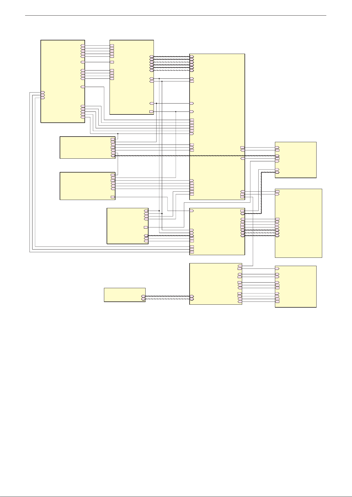
GRUNDIG Service Chassis G5
Power Supply
FRC
Chassisplatte – Übersicht / Chassis Board – Overview
LDIM_U10_SPI_DI
LDIM_U10_SPI_CS
LDIM_U10_SPI_DO
LDIM_U10_VSYNC
FRC_TCON_ON
LDIM_G7_SPI_CS
LDIM_G7_SPI_CK
LDIM_G7_SPI_DI
LDIM_G7_SPI_DO
3D_EN/ SC_BL_EN
LAN/USB
IR/Keyboard
FRC-SCK
FRC_BL_CTRL
FRC_DIM0
FRC_DIM1
FRC_DIM2
G7_TCON_ON
G7_BL_ON
POWER_SW
BRI_ADJ
3D_EN/ SC_BL_EN
3D_SYNC_PANEL_O
URSA_RST
WLAN_EN
WOWL
USB_CTRL
3D_SYNC_OUT
SCART
3D_SYNC_OUT
3D_SYNC_FRC_O
KEY_ADC
PM_PWM
3D_SYNC_G7_O
IRIN
FLASH
FRC-SCK
LDIM_U10_SPI_DI
LDIM_U10_SPI_CS
LDIM_U10_SPI_DO
LDIM_U10_VSYNC
FRC_BL_CTRL
FRC_TCON_ON
FRC_DIM0
FRC_DIM1
FRC_DIM2
Amplifier
LVDSxA
LVDSxB
LVDSxC
LVDSxD
I2C-SDA
I2C-SCL
URSA_RST
3D_SYNC_FRC_O
I2C-SDA
I2C-SCL
MUTE_AMP
PD-AMP
MUTE
I2S
HP_Audio-L
HP_Audio-R
FLASHDATA
FLASH
LVDSA
LVDSB
Scaler-SOC/LVDS
LVDSA
LVDSB
LVDSxA
LVDSxB
LVDSxC
LVDSxD
I2C-SDA
I2C-SCL
URSA_RST
3D_SYNC_FRC_O
LDIM_G7_SPI_CS
G7_TCON_ON
G7_BL_ON
POWER_SW
BRI_ADJ
3D_EN/ SC_BL_EN
WLAN_EN
WOWL
USB_CTRL
KEY_ADC
PM_PWM
3D_SYNC_G7_O
3D_SYNC_PANEL_O
PD-AMP
Scaler-SOC
I2C-SCL
I2C-SDA
I2S
HP_Audio-L
HP_Audio-R
LDIM_G7_SPI_CK
LDIM_G7_SPI_DI
LDIM_G7_SPI_DO
PCMCIA-Interface
FLASHDATA
FLASH
UART-TX
UART-RX
SC-HSYNC
HDMI_DETECTMUTE_AMP
EDID_WP
PCM_PWR_CTL
SPDIF-OUTIRIN
SCART_AUDIO
MHL_CABLE_DET
HDMI_CEC
HDMI_ARC
MHL_VBUS_EN
HDMIA
HDMIC
HDMID
PCM_PWR_CTL
TUNER_FEF
I2CM_SDA
I2CM_SCL
IFAGC_T
DIF_P
DIF_N
DiSEqC_out
IFAGC_S
QP_S
IP_S
SCART/SERVICE/SPDIF
UART-TX
UART-RX
SCART
SC-HSYNC
MUTE
SPDIF-OUT
SCART_AUDIO
HDMI
HDMI_DETECT
EDID_WP
MHL_CABLE_DET
HDMI_CEC
HDMI_ARC
MHL_VBUS_EN
HDMIA
HDMIC
HDMID
Tuner
TUNER_FEF
I2CM_SDA
I2CM_SCL
IF_AGC_T
DIF_P
DIF_N
DISEQC_OUT
IF_AGC_S
QP_S
IP_S
2 - 6
Page 53
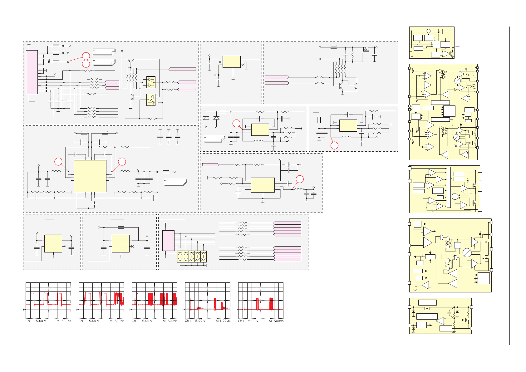
Chassisplatte – Netzteil / Chassis Board – Power Supply
L915
VFB2
VFB1
5
1
2
OCP2 ZC2
GND
T
T
VREG5
VBST
VFB
UT
VIN
1 2 3
4
5
TP102
VCC_ST
TP103
22pFC944
BL_CTRLX
VCC_ST
VCC3V3
1
3
+5V2_ST
VCC_ST
1NF C945
IC904
5
6
7
8
TP118
C937
1uF
Tr igger
7
8
R9081k
SCANNING BL
R918
1K*4
R9061k
LOCAL DIMMING
4
3
1
L906
3A
10UFC921 10UFC922
100NFC925
4
VBST1
SW1
PGND1
EN1
PG1
VFB19GND10VREG511VFB2
EPAD
17
325mA
VCC3V3-ST
3
L901
+12V
L914
TP105
V_AUDIO
TP106
TP107
TP109
TP110
TP111
TP112
C906
1NF
22pFC943
22pFC942
1 2
L909
3.3UH
C931
22UF
6.3V
R924
R923
1.8K
0R
VCC3V3
TPS2530
IC905
OUT
IN
FLT
EN
GND
2
PSU with 5V
PSU without 5V
POWER_SW
BRI_ADJ
5
LDIM_SPI_CK
6
LDIM_SPI_DI
72
LDIM_SPI_CS
8
LDIM_VSYNC
4*0RR937
L907
60R3A
R934
1
VIN22VIN1
VBST2
SW2
PGND2
EN2
PG2
TPS542941RSAR
12
C934
1UF
C940
1uF
POWER_SW
FRC_DIM0
FRC_DIM1
FRC_DIM2
BC847BPDW1T1
100NFC926
16
15
14
13
VCC3V3_FE
IC906 TPS2530
5
IN
4
EN
+5V2_ST
T900A
+12V
R933
NC
L911
3.6A
6.3UH
R928
0R
OUT
FLT
GND
2
T900B
4 3
5
7
8
1
2
6
1
BL_CTRLX
VCC5V_DCDC
10V
10UF
R927
2.7K %1
L913
NC
1
3
TP104
BC847BPDW1T1
3D_EN/ SC_BL_EN
5
6
R901
10K
2
1
3
4
2
3
R905
POWER_SW
C930
VCC3V3_FE
D900
BAT54CW
D901
BAT54CW
TP116
C933C932C929
R925
15.4K %1
C935
22PF
TP119
C938
1uF
3D_EN/ SC_BL_EN
R929
3
47R
R930
47R
1
2
47R
C924 C927 C928
3000mA
L910
+5V2_ST
60R
3A
PSU without 5V
RESERVED FOR LDIM
S901
7
NC
1
P1
2
P2
GND
3
P3
4
P4
5
P5
6
P6
GND
8
G7_BL_ON
FRC_BL_CTRL
D904
2 - 7
S900
16
P1
P2
GND
P3
P4
P5
P6
P7
P8
P9
P10
P11
P12
P13
GND
P14
15
1300mA
VCC3V3-ST
TP117
22UF
R926
6.2K
450mA
VCC3V3-ST
C939
1uF
POWER_SW
1
2
3
4
5
6
7
8
9
10
11
12
13
14
22PFC936
5
4
D905
D906
VCC3V3-ST
VCC1.8V
240mA
+12V
non STR option
POWER_SW
LDIM_SPI_CK
LDIM_SPI_DI
LDIM_SPI_CS
LDIM_SPI_DO
LDIM_VSYNC
D907
D908
C902
1UF
+V
D902
+5V2_ST
R921
12K
VDDC
XC6222B181ER-G
IC900
1
VIN
2
NC
VOUT3NC
TP207
10UF
C903
6.3V
L902 60R 1.7A
D903
10UF
C910
POWER_SW
LDIM_SPI_CK
LDIM_SPI_DI
LDIM_SPI_CS
LDIM_SPI_DO
LDIM_VSYNC
LDIM_SPI_DO
LDIM_SPI_CS
LDIM_SPI_DI
LDIM_SPI_CK
LDIM_VSYNC
R920
R919
VSS
EPAD
7
100NF
C911
CE
3
R935
NC
0R
10K
C923
470nF
6
5
4
POWER_SW
R931 NC
IC901
1
GND
2
SW
VIN3VFB
TPS562200DDCR
L904
3.3UH
NR4018T3R3M
R936
0R
IC903TPS56528
1
EN
2
VFB
3
VREG5
4
PG
4*0RR907
FRC-SCK
LDIM_U10_SPI_DI
LDIM_U10_SPI_CS
LDIM_U10_SPI_DO
LDIM_U10_VSYNC
0RR909
4*0RR922
LDIM_G7_SPI_DO
LDIM_G7_SPI_CS
LDIM_G7_SPI_DI
LDIM_G7_SPI_CK
BRI_ADJ
0RR932
100NFC904
VBST
EN
VBST
EPAD
9
G7_TCON_ON
FRC_TCON_ON
6
5
4
C908
22PF
C912
47UF
VCC_ST
8
VIN
7
6
SW
5
GND
LDIM_U10_SPI_DI
LDIM_U10_SPI_CS
LDIM_U10_SPI_DO
LDIM_U10_VSYNC
LDIM_G7_SPI_DO
LDIM_G7_SPI_CS
LDIM_G7_SPI_DI
LDIM_G7_SPI_CK
G7_TCON_ON
FRC_TCON_ON
R910
POWER_SW
100k
C946
NC
R912 15.4k %1
R914 15.4k %1
R916 0R
VCC1.5V
TP114
1050mA
C916 22uF
C920
100NF
C917
100NF
FRC-SCK
BRI_ADJ
L900
+12V PANEL_PWR
VCC3V3-ST
R903 0R
R904 0R
+V
10UF
C913
5
5250mA
VDDC
L908
C919
C918
1.5UH
47UF
100NF
C900
4.7uF
Hi: Off
Lo: On
TP108
T902A
BC847BDW1T1G
L903
60R
1
1.7A
2
100NF
C914
4
R902
4*22K
5
4 3
IC902
GND
VBST
SW
VIN3VFB
TPS562200DDCR
L905
3.3UH
NR4018T3R3M
2
100NFC905
EN
R900
20K
T902B
1 6
1
T901
PMV65XP
6
5
4
C909
22PF
C915
47UF
32
C901
100NF
R911
POWER_SW
100k
22PFC907
R913 15.4k %1
R915 15.4k %1
R917 6.2K %1
VCC1.18V
TP113
1150mA
PG1
EN1
EN2
GND
PG2
VFB
IN
EN
EN
PG
Charge
Pump
UVLO
TPS2530
-16%
PGND
+16%
-32%
SS1
PGND
EN
Logic
Fixed
SoftStart
PGND
PGND
TPS542941
5EN
4
Voltage
Reference
Soft Start
OCL
threshold
TPS562200
TPS563200
TPS562209
EN
1
Logic
+25%
REF
SS
2
3
UVLO
Softstart
REF
4
Current
Sense
Ref1
-32%
SS2
-16%
+16%
EN Logic
SS1
SS2
Ref2
V
UVP
+
+
-
Current
Limit
+
-
PWM
VREG5
CS
OTSD
PG
Comp
UV1
Err
Comp
+
UVP
V
OVP
+
+
OCL
+
EN
VIN
EN
SS
REF
+
-
8-ms
Driver
Deglitch
Thermal
Sense
Control logic
OCP1
CH1Min-off timer
UV1
UV2
Protection
UVLO
TSD
CH2Min-off timer
Control logic
UV2
Err
Comp
PG
Comp
Hiccup
+
OVP
PWM
Ton
One-Shot
TSD
ZC
+
OV
REF
-10%
OU
FLT
XCON
Ref_OCL
SW1
Logic
XCON
Ref_OCL
SW2
Regulator
UVLO
Control Logic
XCON
TPS56528
Control Logic
1 shot
ON
+
ZC
-
+
OCP
-
Ref1
Ref2
VREG5
SW
PGND
SW
PGND
VREG5
ZC1
HS
VREG5
LS
VIN1
5VREG
REF
UVLO
VREG5
XCON
UVLO
PGND1
SW1
PGND2
SW2
VREG5
OV
TSD
VIN1
VBST1
SW1
PGND
VREG
VIN2
VBST2
SW2
PGND
3 VIN
6
2SW
1GND
VREG5
Protection
Logic
GRUNDIG Service Chassis G5
8
VIN
7
VBS
6
SW
5
GND
CE
Reverse Current
Current Limit &
Thermal Shoutdown
ON/OFF
Control
Protection
each
circuit
XC6222D
CFB
Error
Amp.
+
-
Voltage
Reference
R2
R1
VO
Rdischg
/CE
VSS
Page 54
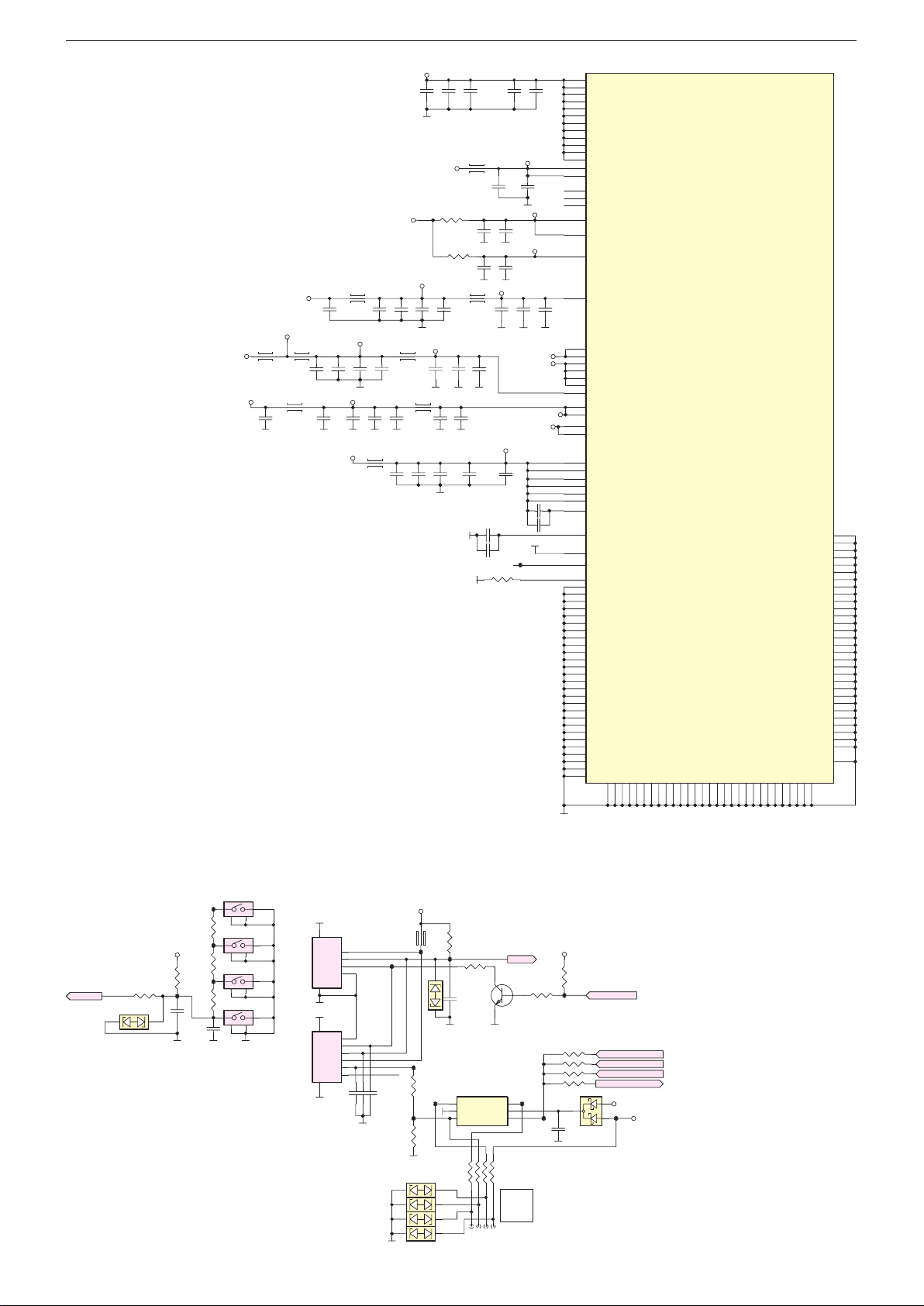
GRUNDIG Service Chassis G5
3.3VST-> 270m
IC100F
MSD93F1TW2
VDDC
(+)
TP15
TP15
G
TP157TP15
Chassisplatte – Netzteil / Chassis Board – Power Supply
VDDC-> 5250mA
VCC3V3-ST
3.3V-> 360mA
A
VCC3V3
VCC3V3-ST
VCC3.3VA_AG
L303
C311
22uF
C309
22UF
C312
L304 L305
100NF
VCC3.3V_AG
C342
L306 L307
22uF
1.5V-> 810mA
C326
L301 L302
100NF
VCC3.3VA_AG1
C313
C314
C332
470nF
100NF
100NF
C319
C320
100NF
22uF
VCC1.5V
L308
VDDC
VCC3.3VA_AG2
C315
100NF
AVDD_DMPLL
C333
100NF
C335
22uF
C300
47UF
VCC1.18V
C316
22uF
C336
100NF
C310
100NF
C334
100NF
C322
22uF
C302
100NF
R301
0R
R302
C340
470nF
C329
470nF
0R
470nF
C331
100NF
C321
100NF
C338
C303
100NF
L300
C323
100NF
MCP-> 300mA
NC
C306
100NF
C307
100NF
AVDD_AU
C339
470nF
AVDD-DDR
R303
0R
C304
NC/
100NF
MCP_VDDC
C305C308
470nF
DVDD_DDR
C318
100NF
AVDDL_DVI
C330
100NF
C317
C327
100NF
100NF
VCC3.3VA_AG2
VCC3.3VA_AG1
AVDD_MOD
VCC3.3V_AG
C325
470nF
C328
470nF
C337
470nF
AVDD5V_HDMIC
TP67
VSENSE
GND_EFUSE
C301
NC/
47UF
C341
470nF
J14
J15
K14
K15
K16
K17
K18
L14
L15
L16
L17
L18
U5
V5
P15
J17
J16
J13
K13
L13
T6
U6
V6
L4
L5
L6
L7
L8
H6
H7
H4
H5
K12
J12
L12
M12
N12
N13
M11
K11
W8
H15
J8
A13
A15
A18
B12
B14
B16
B17
B19
B20
C9
C10
C21
D9
E20
F11
F13
F15
F17
F19
F21
G8
G9
G10
G11
G12
G13
F9
VDDC
VDDC
VDDC
VDDC
VDDC
VDDC
VDDC
VDDC
VDDC
VDDC
VDDC
VDDC
W_VDDC
W_VDDC
CTRL_SRAM_LDO
VDDC_SRAM
VDDC_SRAM
DVDD_DDR_B
DVDD_DDR_A
AVDDL_DVI
AVDD_AU33
AVDD3P3_USB
AVDD3P3_USB
AVDD_NODIE
AVDD3P3_ADC
AVDD3P3_DADC
AVDD3P3_ETH
AVDD3P3_DMPLL
AVDD_MOD
AVDD_MOD
VDDP/VDDP_3318
AVDD_PLL
AVDD_DDR1_C
AVDD_DDR1_D
AVDD_DDR0_C
AVDD_DDR0_D
VDDIO_DRAM
VDDIO_DRAM
AVDD04_DDR
AVDD11_DDR
AVDD_5V_HDMI_C
VSENCE
GND_EFUSE
GND
GND
GND
GND
GND
GND
GND
GND
GND
GND
GND
GND
GND
GND
GND
GND
GND
GND
GND
GND
GND
GND
GND
GND
GND
GND
GND
GND
GND
GND
GND
G15
G14
G16
G17
GND
G18
GNDH9GND
GND
H11
H10
AA20
GND
Y2
GND
V3
GND
W6
GND
R13
GND
R12
GND
R11
GND
R9
GND
R8
GND
R7
GND
P14
GND
P13
GND
P11
GND
P10
GND
P9
GND
P8
GND
P7
GND
P6
GND
P5
GND
P4
GND
P3
GND
N18
GND
N17
GND
N16
GND
N15
GND
N14
GND
P12
GND
N11
GND
N10
GND
N9
GND
M18
GND
GND
GND
GND
GND
GND
GND
GND
GND
GND
GND
GND
L9
K4
K9
K8
J11
M9
L11
L10
K10
GND
GND
J9
J10
H13
H14
H18
H12
GND
GND
GND
GND
GND
GND
GND
GND
M16
M14
M13
M17
M15
M10
Chassisplatte / Chassis Board – IR/Keyboard
22pF
C1206 22pF
C1205
TP212
D1203
D1204
D1205
D1206
+5V2_ST
L1200
240R
0.25A
DMY
TP151
R1212
10K
1 2
1 2
1 2
1 2
TP211
R1215
1k
KEY_ADC
KEYPAD
KEY_ADC
D1201
1 2
R1208
100R
VCC3V3-ST
R1203
1K
TP149
C1201
47pF
TP208
R1200
TP209
R1202
470R
TP210
R1207
270R
C1202
100nF
1K
1 2
4
3
V/P
1 2
3
4
(-)
1 2
3
4
ST-BY
1 2
3
4
S1200
S1201
S1203
S1204
6
GND
S1202
GND
5
7
GND
S1206
GND
3D OPTION
8
4
P4
3
P3
2
P2
1
P1
1
P1
2
P2
3
P3
4
P4
5
P5
6
P6
22pF
C1204
TP147
D1202
TP213
R1201
TP1201 ALSO USED FOR AUTOMATION SYSTEM
10k
TP148
IRIN
R1205
560R
2
1
C1200
47pF
IC1200
1
2
PB0
GND
VCC
PB13PB2
8
7246
1
3
6
5
4
PB3
5
32
R1214
100R
IRIN
1
T1200
BC847B
TP214
6
5
4
TPI CLK
RST
TPI DATA
VCC3V3-ST
R1206
10K
R1209 1k
R1210 1k
R1211 1k
R1213 NC
TP153
5V
C1203
100nF
R1204
47K
3
D1200
BAT54CW
PM_PWM
3D_SYNC_G7_O
3D_SYNC_FRC_O
3D_SYNC_PANEL_O
3D_SYNC_OUT
1
VCC3V3
TP152
2
VCC5V_PRO
2 - 8
Page 55
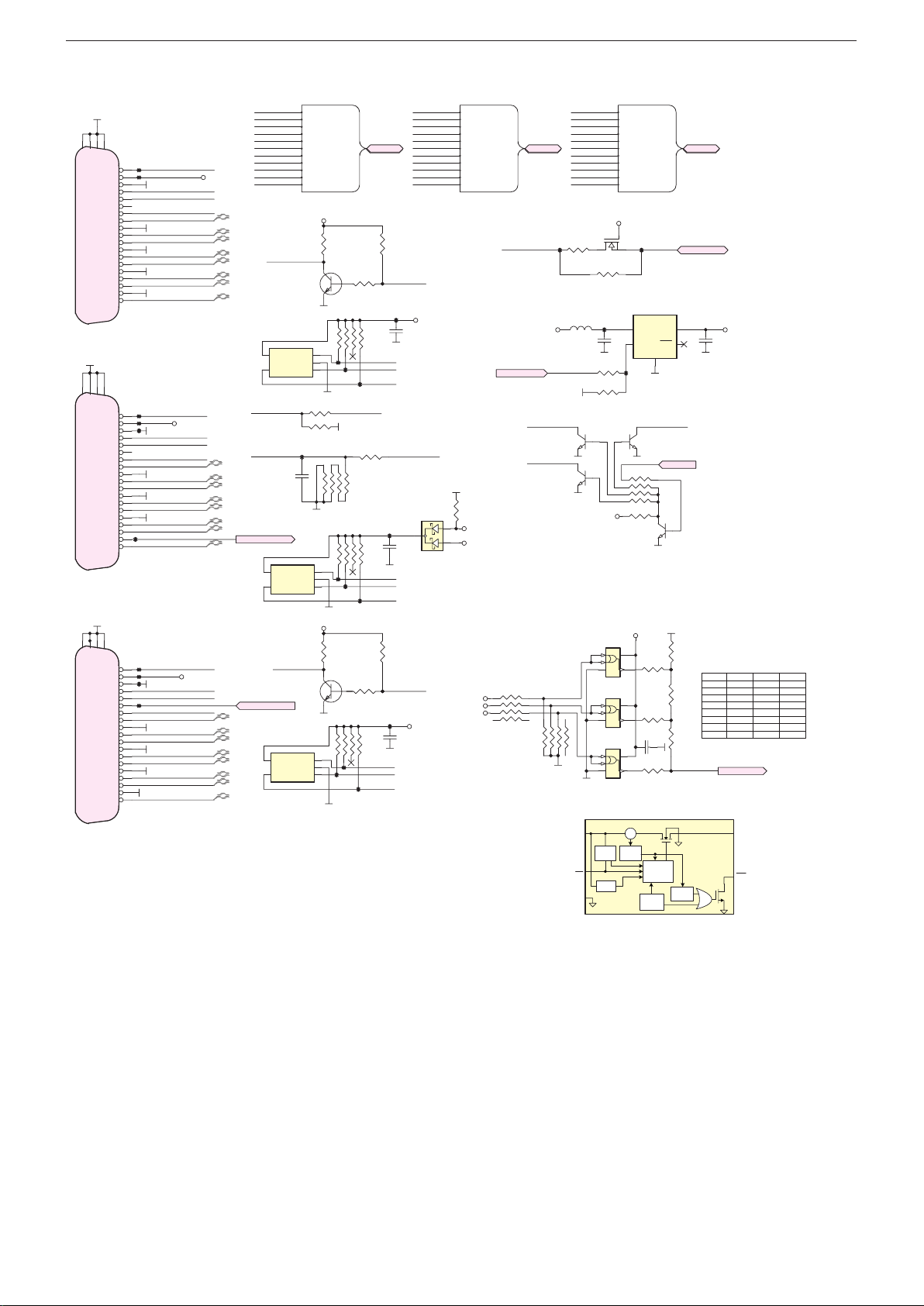
GRUNDIG Service Chassis G5
HDMIA
HDMIC
HDMID
HDMI1 HDMI2HDMI3
E
S906
T
EN
Chassisplatte / Chassis Board – HDMI
21
GND20GND
HP_DETECT
CEC_GND
GND_CLK
S1100
21
GND20GND
HP_DETECT
CEC_GND
GND_CLK
S1101
21
GND20GND
HP_DETECT
CEC_GND
GND_CLK
22
GND
CLK-
CLK+
RX0-
GND0
RX0+
RX1-
GND1
RX1+
RX2-
GND2
RX2+
GND22GND
CLK-
CLK+
RX0-
GND0
RX0+
RX1-
GND1
RX1+
RX2-
GND2
RX2+
22
GND
CLK-
CLK+
RX0-
GND0
RX0+
RX1-
GND1
RX1+
RX2-
GND2
RX2+
SDA
N.C.
CEC
SDA
N.C.
CEC
SDA
N.C.
CEC
HDMIA
TP143
R1101
10K
TP122
MHL_CABLE_DETMHL-CABLE-DET
R1113
10K
HDMIA-HPD
C1100
100nF
3
TP134
C1104
100nF
HDMID-HPD
HDMID-5V
C1105
100nF
HDMIC-RX0_N
HDMIC-RX0_P
HDMIC-RX1_N
HDMIC-RX1_P
HDMIC-RX2_N
HDMIC-RX2_P
HDMIC-CLK_N
HDMIC-CLK_P
HDMIC-SCL
HDMIC-SDA
HDMIC-HPD
HDMIA-5V
AVDD5V_HDMIC
D1100
BAT54CW
R1109
10R
1
2
HDMIC-5V
HDMIA-5V
HDMID-5V
HDMIC
TP123
MHL_VBUS_EN
EE_WPA
T1101A
EE_WPC
T1102B
3
4
5
6
HDMID-RX0_N
HDMID-RX0_P
HDMID-RX1_N
HDMID-RX1_P
HDMID-RX2_N
HDMID-RX2_P
HDMID-CLK_N
HDMID-CLK_P
HDMID-SCL
HDMID-SDA
HDMID-HPD
HDMIC->MHL SUPPORT
R1116
220R
L1100
3.3uH
3
NC
4
NC
1 6
1
2
7
8
IN
or
EN
GND
VCC3V3
HDMIC-RX0_N
HDMIC-RX0_P
HDMIC-RX1_N
HDMIC-RX1_P
HDMIC-RX2_N
HDMIC-RX2_P
HDMIC-CLK_N
HDMIC-CLK_P
HDMIC-SCL
HDMIC-SDA
HDMIC_HPD
HDMI_CECIN HDMI-CEC
VCC5V_DCDC
MHL_VBUS_EN
HDMIC-5V
+5V2_ST
R1122
1
8
7 2
3
6
5
4
4.7K
R1125
100K
+5V2_ST
3 2
T1104
2N7002LT1G
R1117
NC
TP128
C1101
10UF
R1107
100R
R1108
10K
5
2
IC1104
NC7SZ08P5X
1
VCC
2
GND
IC1105
NC7SZ08P5X
1
VCC
2
GND
IC1106
NC7SZ08P5X
1
VCC
2
GND
Current Sense
Charge
Pump
UVLO
HDMID-RX0_N
HDMID-RX0_P
HDMID-RX1_N
HDMID-RX1_P
HDMID-RX2_N
HDMID-RX2_P
HDMID-CLK_N
HDMID-CLK_P
HDMID-SCL
HDMID-SDA
HDMID_HPD
1
IC1101
TPS2065C
5
IN
4
EN
TP129
2
1 6
EDID_WP
R1111
1
3
NC
R1114
NC
VCC3V3
5
43
5
R1123
43
20K
C1106
5
100NF
43
CS
Current
Limit
OTSD
Thermal
TP124
OUT
FLT
GND
2
EE_WPD
T1101B
HI->PROTECTION
EDID_WP
8
6
5724
5
4 3
T1102A
R1119
20K
R1120
20K
R1121
10K
R1124
10K
R1126
HDMI_DETECT
20K
Driver
9-ms
Deglitch
Sense
HDMID
HDMI_CEC
1
HDMIC-5V
C1102
3
10UF
HDMI DETECT ANALOG LEVEL TABL
HDMI1 HDMI2 HDMI3 LEVEL
NO NO NO 0
YES NO NO 1,65
NO YESNO 0,82
YES YESNO2,47
NO NO YES 0,41
YES NO YES2,06
NO YESYES 1,24
YES YES YES 2,89
HDMI_DETECT
OU
TPS20xxC
FLT
HDMIA-RX0_N
HDMIA-RX0_P
HDMIA-RX1_N
HDMIA-RX1_P
23
GND
19
HDMIA-HPDOUT
TP120
18
TP121
5V
17
16
HDMIA-SDA
15
14
13
12
11
10
9
8
7
6
5
4
3
2
1
19
18
17
16
TP133
15
14
13
12
11
10
9
8
7
6
5
4
3
2
1
19
18
17
16
15
14
13
12
11
10
9
8
7
6
5
4
3
2
1
TP131
TP132
TP135
TP139
TP140
TP141
TP142
HDMIA-SCL
HDMI_CECIN
HDMIA-CLK_N
HDMIA-CLK_P
HDMIA-RX0_N
HDMIA-RX0_P
HDMIA-RX1_N
HDMIA-RX1_P
HDMIA-RX2_N
HDMIA-RX2_P
HDMIC-HPDIN
HDMIC-SDA
HDMIC-SCL
HDMI_CECIN
HDMIC-CLK_N
HDMIC-CLK_P
HDMIC-RX0_N
HDMIC-RX0_P
HDMIC-RX1_N
HDMIC-RX1_P
HDMIC-RX2_N
MHL_CABLE_DET
HDMIC-RX2_P
HDMID-HPDOUT
HDMID-SDA
HDMID-SCL
HDMI-ARC
HDMI_CECIN
HDMID-CLK_N
HDMID-CLK_P
HDMID-RX0_N
HDMID-RX0_P
HDMID-RX1_N
HDMID-RX1_P
HDMID-RX2_N
HDMID-RX2_P
SCL
23
5V
SCL
23
GND
5V
SCL
HDMIA-5V
HDMIC-5V
HDMID-5V
HDMIA-RX2_N
HDMIA-RX2_P
HDMIA-CLK_N
HDMIA-CLK_P
HDMIA-SCL
HDMIA-SDA
HDMIA-HPD
4
5
HDMIC-HPDIN HDMIC-HPD
MHL_CABLE_DET
HDMI_ARC
HDMIA-HPDOUT
IC1100
SDA
VCC
GND
SCL
WP
NC
C1103
47nF
IC1102
4
SDA
VCC
GND
5
SCL
WP
NC
HDMID-HPDOUT
IC1103
4
SDA
VCC
GND
5
SCL
WP
NC
HDMIA-RX0_N
HDMIA-RX0_P
HDMIA-RX1_N
HDMIA-RX1_P
HDMIA-RX2_N
HDMIA-RX2_P
HDMIA-CLK_N
HDMIA-CLK_P
HDMIA-SCL
HDMIA-SDA
HDMIA_HPD
HDMIA-5V
R1100
1K
32
3
2
1
TP125
R1104 33R
R1127 NC
TP130
3
4
5
6
3
2
1
TP136
HDMID-5V
R1112
1K
3
2
3
2
1
T1100
BC847B
5
4
TP126
2
7
5
4
TP137
BC847B
5
4
TP144
TP145
1
R110247K
7
6
3
2
TP127
1
R1106
100K
8
7
6
3
2
T1103
1
R111547K
7
6
3
2
TP146
8
R1103
4.7K
1
HDMIA-SDA
HDMIA-SCL
EE_WPA
R1105
0R
8
R1110
4.7K
1
HDMIC-SDA
HDMIC-SCL
EE_WPC
TP138
8
R1118
4.7K
1
HDMID-SDA
HDMID-SCL
EE_WPD
2 - 9
Page 56
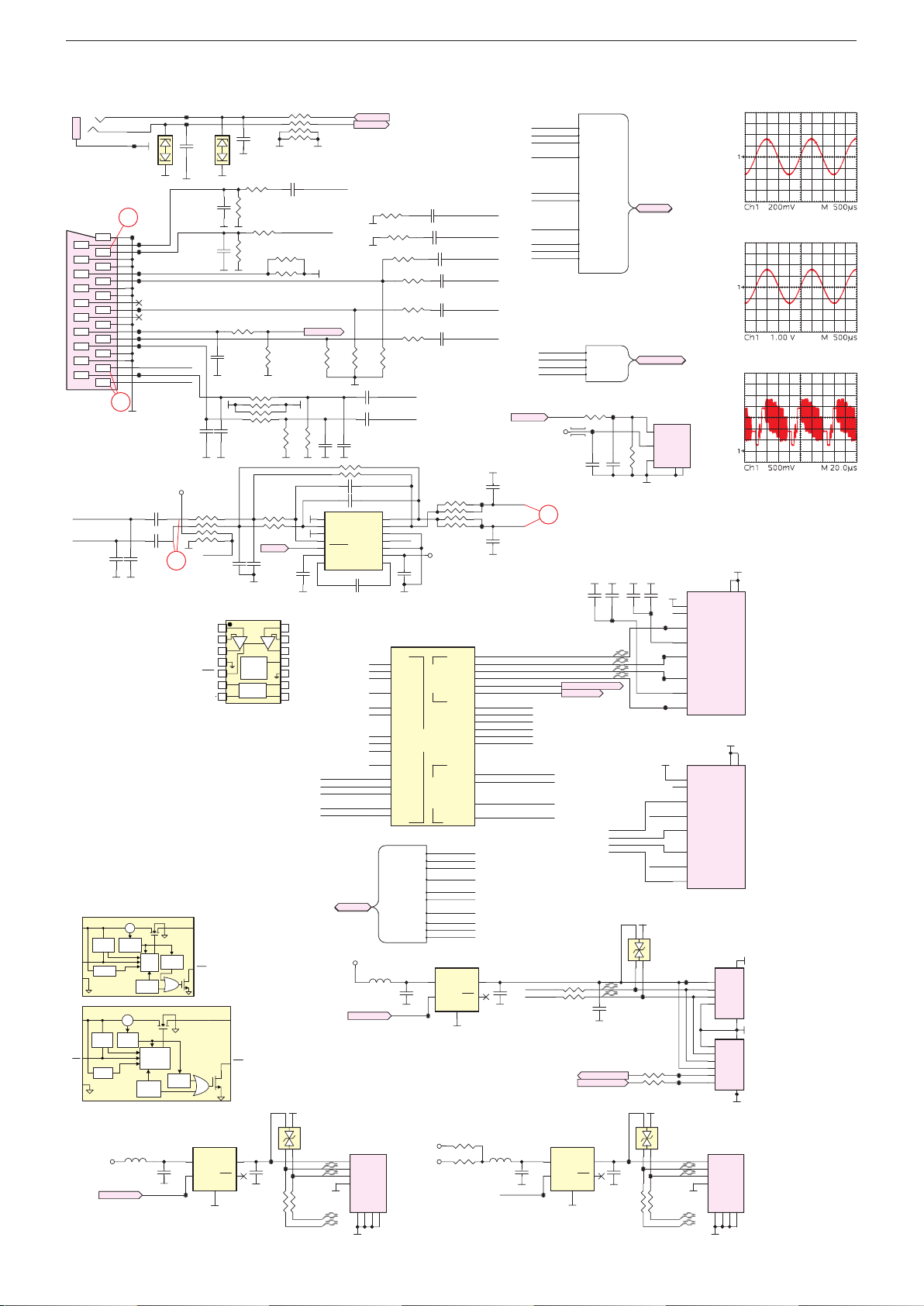
GRUNDIG Service Chassis G5
VCC5V_DCDC
WITHOUT SHIELD WITH SHIELD
OUTR
OUTL
DRV632
1uF
Service Socket
S601
SCAR
GND
T
T
EN
%
^
&
Chassisplatte / Chassis Board – LAN, SCART, SPDIF, USB
S600
CKX-3.5-31(3P)
Full SCART
T
AU-DAC2-L
AU-DAC2-R
IN
EN
IN
or
EN
GND
16
C631
1NF
Current
Sense
Charge
Pump
UVLO
TPS2530
Current Sense
Charge
Pump
UVLO
USB_CTRL
LEFT
RIGHT
GND
17
21
20
19
18
17
16
15
14
13
12
11
10
9
8
7
6
5
4
3
2
1
Current
Limit
CS
Current
Limit
L402
3.3uH
TP183
CS
OTSD
OTSD
TP186
TP187
TP188
TP189
TP190
TP191
TP192
TP193
TP194
TP195
C632
1NF
Driver
Thermal
Sense
Thermal
Sense
Hi: ON
Lo: OFF
1
2
D600
SC-VSYNC
SCART1_RED
SCART1_GREEN
SCART1_BLUE
SCART1-Lin
SC-Lout
SCART1-Rin
SC-Rout
VCC3V3
C621
1uF
C625
1uF
15
8-ms
Deglitch
Driver
Deglitch
C407
10UF
USB_CTRL
9-ms
5
4
TP81
TP184
TP185
C601
NC
C606
100pF
C602
100pF
C614
100pF
R627
7 2
8
6
5
10K
uvp
+INR
–INR
GND
Mute
VSS
CN
OU
FLT
TPS20xxC
IC401
TPS2530
IN
EN
VGA-TX
VGA-RX
1
C600
NC
2
D601
R60433R
R606
75R %1
R602
0R
R603
75R %1
150R %1
R613
10K
C611
47pF
R619
8
7 2
6
5
C615
10K
100pF
1
3
4
C628
470PF
1
2
3
External
4
Under
Voltage
5
Detector
6
Charge
Pump
7 8
OU
FLT
TP78
1
OUT
C408
3
FLT
10UF
GND
2
R626
R629
MUTE
C629
470PF
R618
2.7K %1
TP79
R409
0R
8
7 2
6
5
C603
47nF
SC_CVBS_OUT
R608
R610
SC-HSYNC
1
3
4
R620
12K
39K
39K
C630
1uF
14
+INL
13
–INL
12
11
UVP
10
GND
9
VDD
CP
4
1
3
2
R601
100R
SC_CVBS-IN
150R %1
SC-HSYNC
NC
D402
P0X_N
P0X_P
TP80
R408
0R
P0_P
P0_N
1
UART-TX
UART-RX
3
4
R615
75R %1
R621
12K
C616
100pF
R62247K
R62347K
IC600
1
+INR
2
-INR
14
+INL
13
-INL
5
MUTE
6
PVSS
CN7CP
DRV632PWR
SCART_RIN+
SCART_GINSCART_GIN+
SCART_BIN+
SC-VSYNC
C612
C613
C617
100pF
22pF
C619
C620
22pF
C627
SCART
+5V2_ST
WLAN_EN
S404
1
2
3
4
UART-TX
UART-RX
R616
75R %1
1uF 6.3V
1uF 6.3V
OUTR
OUTL
SGND
UVP
PGND
PVDD
VBUS
DD+
GND
SHLD
8
7
R605
R607
R60933R
R61133R
R61233R
R61433R
R617
75R %1
3
12
4
11
10
9
8
IC100E
K2
K1
K3
J1
G5
G6
M2
M3
L2
L3
N2
N1
N3
M1
G7
MSD93F1TW2
SCART_RIN+
SCART_GIN-
SCART_GIN+
SCART_BIN+
SC_CVBS-IN
SC_CVBS_OUT
L400
3.3uH
WLAN_EN
SHLD6SHLD
SHLD
5
RIN0P
GIN0M
GIN0P
BIN0P
HSYNC0
VSYNC0
RIN1P
GIN1M
GIN1P
BIN1P
RIN2P
GIN2M
GIN2P
BIN2P
VSYNC2
SCART_C
SC-VSYNC
SC-HSYNC
VCC5V_DCDC
68R
C604 47nF
68R
C605 47nF
C607 47nF
C608
47nF
C609
47nF
C610
47nF
SC-Rin
SC-Lin
R625
1
3
4
1K
uvp
VCC3V3
C626
1uF
PHYCVBS
GPIO19
GPIO20
DM_P0
DP_P0
DM_P1
DP_P1
USB
DM_P2
DP_P2
RGB
CVBS1P
CVBS0P
VCOM0
CVBS_OUT1
SCART
SCART_RIN+
SCART_GIN-
SCART_GIN+
SCART_BIN+
SC_CVBS-IN
SCART_C
SC_CVBS_OUT
CVBS-
CVBSSC-VSYNC
SC-HSYNC
IC402
TPS2065C
5
IN
C409
4
EN
10UF
TP73
Hi: ON
Lo: OFF
STANDBY CHARGE OPTION
R404 0R
+5V2_ST
R405 0R
2 - 10
SCART_GIN-
CVBS-
SCART_C
SCART_RIN+
SCART_GIN+
SCART_BIN+
TP198
8
72
6
5
TP199
RN
RP
TN
TP
OUT
FLT
GND
2
C618
47pF
SC-Lout
SC-Rout
C624
47pF
A6
MDI_R_N
B6
MDI_R_P
C6
MDI_T_N
B5
MDI_T_P
C7
3D_EN/ SC_BL_EN
C5
URSA_RST
P0_N
Y9
P0_P
AA9
W9
P1_N
AA10
P1_P
H20
P2_N
H19
P2_P
J6
SCART_C
K6
SC_CVBS-IN
K5
CVBS-
J5
SC_CVBS_OUT
1
C410
3
10UF
L401
3.3uH
Hi: ON
Lo: OFF
SPDIF-OUT
C405
22UF
USB_CTRL
SCART_RIN+
SCART_GINSCART_GIN+
SCART_BIN+
SC_CVBS-IN
SCART_C
SC_CVBS_OUT
CVBSSC-VSYNC
SC-HSYNC
AU-DAC2-L
AU-DAC2-R
SC-Lin
SC-Rin
SPDIF-OUT
VCC3V3
16
P2_N
R400 0R
P2_P
R401 0R
IC400
TPS2065C
5
IN
4
EN
TP77
SCART
SCART_RIN+
SCART_GINSCART_GIN+
SCART_BIN+
SC_CVBS-IN
SCART_C
SC_CVBS_OUT
CVBSSC-VSYNC
SC-HSYNC
SCART_AUDIO
AU-DAC2-L
AU-DAC2-R
SC-Lin
SC-Rin
R624 100R
TP197
L600
C622
100nF
C401
1uF
3D_EN/ SC_BL_EN
URSA_RST
C404
10UF
WOWL
3D_SYNC_OUT
1
OUT
3
FLT
GND
2
TP196
C623
10pF
C402
100NF
TP69
MDI_R_N
MDI_R_P
MDI_T_N
MDI_T_P
TP70
TP72
TP74
C406
TP75
22UF
R407
0R
SCART
SCART_AUDIO
S602
1
2
R628
3
10k
OPT-111
C400
C403
1uF
100NF
TP71
RDCT
TP203
TDCT
RDCT
TDCT
4
1
D400
NC
3
2
P2X_N
P2X_P
R402
270R
R403
270R
NC
D401
4
1
2
3
P1X_N
P1X_P
TP76
R406
0R
P1_P
P1_N
Vin
Vcc
GND
TP201
TP202
TP204
SHIELD4SHIELD
8
7
6
5
3
2
4
1
8
7
6
5
3
2
4
1
5
S401
CH_GND
NC
RD-
RDCT
RD+
TD-
TDCT
TD+
RJ45MAG TS-20001
S405
CH_GND
NC
RD-
RDCT
RD+
TD-
TDCT
TD+
RJ45MAG TS-20001
1
TP68
P1
2
P2
3
P3
4
P4
6
P6
5
P5
4
P4
3
P3
2
P2
1
TP205
P1
TP206
S403
1
VBUS
2
D-
3
D+
4
GND
8
10
GND19GND2
10
GND19GND2
5
GND
GND
6
8
S402
GND
GND
7
SHLD5SHLD6SHLD7SHLD
S400
MOLEX CLICK MATE 4PIN
Page 57
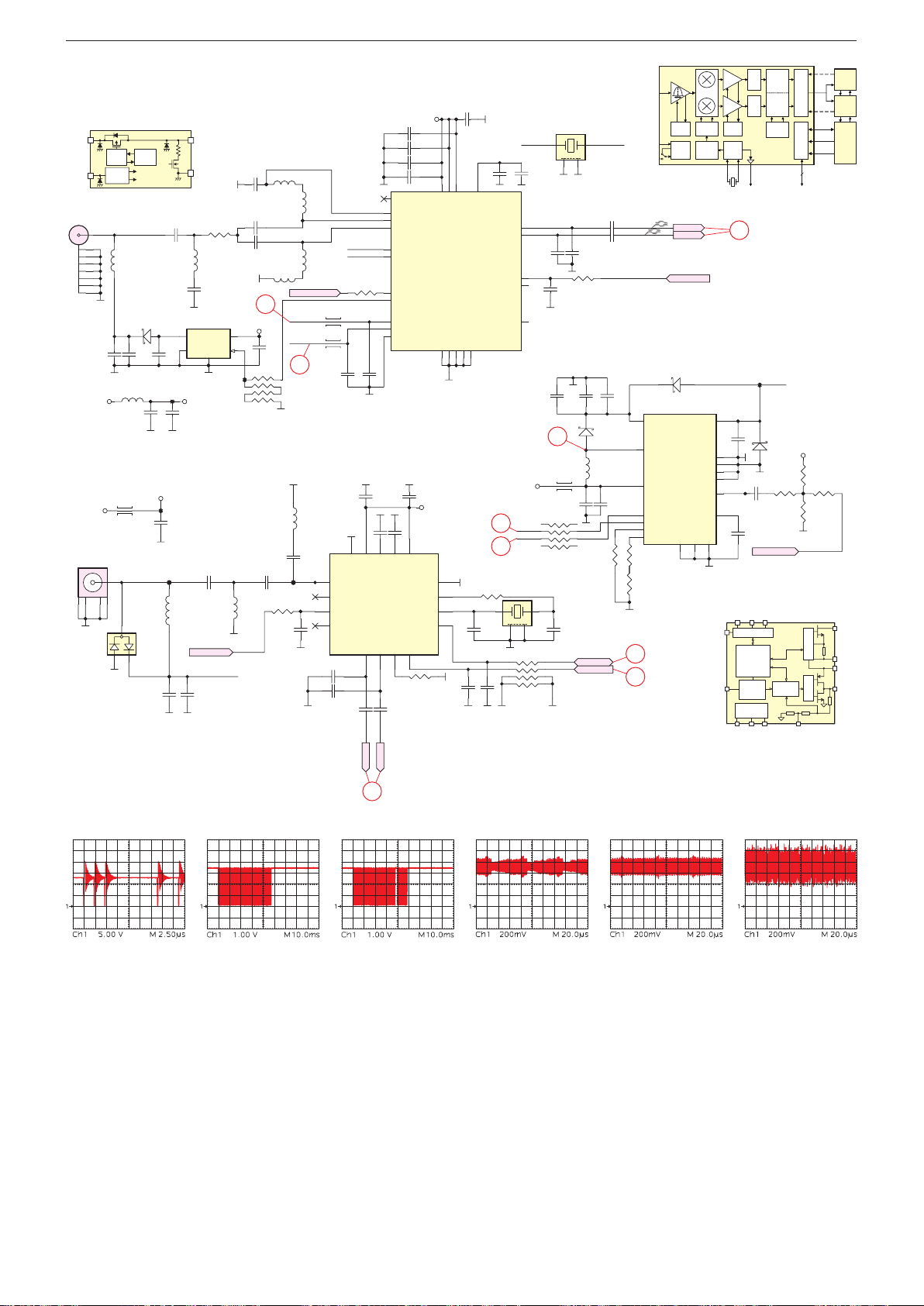
GRUNDIG Service Chassis G5
TERRESTRIAL TUNER
VCC3V3_F
SDASCL
ADDR
VCCBYPGND
EXTM
DSQIN
ANT.
out
CE
6
!
@
#
#
$
Chassisplatte / Chassis Board – Tuner
Vin
S700
1
2
3
4
5
6
7
8
AJ-35
C717
100NF
VCC3V3_FE
E
SAT 1
S701 COAX_F
1
3
4
Gate
Control
ON/OFF
Control
270nH
L709
2
5
1
L703
L708
3.3uH
3
XC8101
Current
Limit
CE
/CE
D700
PMEG4010EH
C718
VCC3V3_FES
C727
10UF
D704
NUP1301U
2
C749
1nF
each
circuit
C724
TP87
22uF
/CE
C709
47pF
C720
100NF
150mA max
TP88
L713
27nH
0.59A
V
Rdischg
Vss
R700
L704
180NH
C715
180PF
IC701
1
Vout
EPAD
GND2CE
5
XC8101AA01GR-G
VCC3V3_FET
C723
xxmA max
100NF
75 ohm Line
IF_AGC_S
LNB_P1
C750
100pF
C706
1NF
C710 39pF
C711 39pF
0R
+5V2_ST
4
Vin
3
R703
TP86
10K*4
4.7PFC731 4.7PFC732
L710
15nH
IF_AGC_S
11
C719
100NF
L700
270NH
L705
270NH
R705
100R
C741
100nF
L701
270NH
L702
270NH
TUNER_FEF
I2CM_SCL
I2CM_SDA
12
L714
NC
C730
NC
C745
10pF
C751
10pF
X_2151
XTALO_T
L706
240R
L707
240R
C721
C722
22PF
22PF
SATELLITE TUNER
C725
100nF
17
EPAD
1
RFIN
2
NC
3
RFAGC
4
RFLP
C744
100nF
R702
NC
16
VCCREG2
RXQP5RXIP
IP_S
VCC3V3_FET
C702
18
NC
19
RF_REF
20
RF_IP
22
RF_IN
13
XTAL_I
14
XTAL_O
24
GPIO1
1
GPIO2
3
SCL
2
SDA
23
ADDR
I2C ADDRESS: C0
C726
100nF
C729
C728
1uF
1nF
14
15
13
CP
REGCAP2
ADDR0
6
8
7
R708 0R
I2C ADDRESS: C4
C746
100nF
QP_S
1NF
1NF
1NFC703
100NFC707
VDDH17VDDH
GND
6
VCC3V3_FES
IC702
AV2018-S85QFG
12
GND
VCCREG1
11
XTAL1
10
XTAL2
9
SDA
SCL
Si2151
100NF
C708
DIF_P
DIF_N
100NF
C714
IF_AGC_T
C734
470nF
25V
12
11
14
16
12
R714
2.2K
6
7
5
8
R713
15.4k %1
IN
3.3V
1.8V
IF_AGC_T
D701
PMEG4010EH
IC703
LNBH29EQTR
VUP
LX
VCC
DSQIN/EXTM
SCL
SDA
ADDR
ISEL
RF
0 / 90 LOW-IF
AGC
FREQ
LDO
SYNTH
DIF_P
DIF_N
VOUT
EPAD
NC
NC
NC
BYP
GND
PGND
9
2
C700
FN1107C
C704
1NF
9
7
15
VDDL
VDDH
LIF_P
LIF_N
AGC1
AGC2
XOUT
GND
GND
EPAD
GND
8
25
16
21
12
11
X701
R704
27MHz
0R
1 3
C738
10pF
C747
10pF
C748
10pF
2
R707
100R*4
X_2151
C705
1uF
IC700
Si2151-A10-GMR
11
10
C712
33PF
5
4
12
+12V
R706
I2CM_SDA
I2CM_SCL
100R*4
4
I2CM_SDA
I2CM_SCL
24MHz
X700
1 3
2
R701
100R
C716
100NF
C743
10uF
35V
6
L712
60R3A
C737
10uF 35V
C739
10pF
XTALO_T
4
C713
33PF
C733
10uF
35V
D702
PMEG4010EH
L711
6.8uH
I2CM_SDA
I2CM_SCL
C736
220nF 50V
R712
10K
4
NC
ISEL
13
220nF
50V
17
15
11
1
3
10
(1)
PGA
PGA
AGC
XOSC
_O
I
ADC
Q
ADC
IF
XOUT
XTAL_I
13
C735
C740
10NF
C742
220nF
50V
I²C Digital core
DAC
Drop control
Tone ctrl
Diagnostics
Protections
Current
Limit
selection
Voltage
reference
FILTER
LNB_P1
TP89
PMEG4010EH
D703
DISEQC_OUT
DSP
R710
0R
LNBH29
Linear
Regulator
OUTPUT
CONTROL
VCC3V3
DISEQC_OUT
R3
R2
AGC
LIF
INTERFACE
AGC
SDA
SCL
ADDR
INTERFACE
GPIO
R709
NC
R711
15.4K
R715
4.7K
PWMCTRL
Gate ctrl
(2)
DEMOD
DEMOD
Isense
DTV
ATV
AV
SoC
LX
PGND
VUP
VOUT
IP_S
QP_S
14
Mode: after pressing P+/P-
Mode: after pressing P+/P-
Mode: ATV
Mode: DVB-C/T
Mode: DVB-S
2 - 11
Page 58
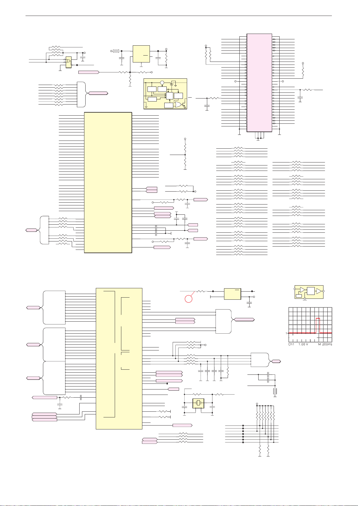
GRUNDIG Service Chassis G5
MSD93F1TW2
S500
IC200
IC100C
HDMIC->MHL SUPPOR
Vc
T
MR
Driver
GND
T
7
Chassisplatte / Chassis Board – PCMCIA-Interface
L500
TP82
C501
10UF
R505
47R
TS0_D0
TS0_D1
TS0_D2
TS0_D3
TS0_D4
TS0_D5
TS0_D6
TS0_D7
TS0_CLK
TS0_VLD
TS0_SYNC
TS1_D0
TS1_D1
TS1_D2
TS1_D3
TS1_D4
TS1_D5
TS1_D6
TS1_D7
TS1_CLK
TS1_VLD
TS1_SYNC
VIFP
VIFM
IFAGC
TGPIO0/UPGAIN
TGPIO1
TGPIO2/ I2C_CLK
TGPIO3/ I2C_SDA
IP_S
IM_S
QP_S
QM_S
IFAGC_S
DISEQ_OUT
CI POWER
TPS2530
IC500
5
4
TP85
R506
4.7K
W11
Y10
W13
Y12
W12
Y13
W10
V10
AA12
AA13
Y11
T9
T8
V9
U7
U9
V7
U10
V8
U8
R10
T10
W1
W2
U4
Y3
T4
W3
Y1
V1
V2
U2
U3
T2
V4
IN
EN
OUT
FLT
GND
2
R502
NC
IN
EN
TS0-D0
TS0-D1
TS0-D2
TS0-D3
TS0-D4
TS0-D5
TS0-D6
TS0-D7
TS0-CLK
TS0-VLD
TS0-SYNC
TS1-D0
TS1-D1
TS1-D2
TS1-D3
TS1-D4
TS1-D5
TS1-D6
TS1-D7
TS1-CLK
TS1-VLD
TS1-SYNC
DIF_N
IFAGC_T
VCC3V3
TGPIO1-C
I2CM_SCL
I2CM_SDA
IP_S
IM_S
QP_S
QM_S
VCC3V3
DiSEqC_out
1
3
+5V2_ST
Current
Sense
Charge
Pump
UVLO
TPS2530
DIF_P
R519
I2CM_SDA
R527
DiSEqC_out
VCC-PCMCIA
TP83
C502
R501
10K
10UF
CS
Current
Limit
Driver
OTSD
Thermal
Sense
MCP Demod H/W straping :
High-0xF2 , Low-0xD2
I2CM_SCL
I2CM_SDA
10K
TUNER_FEF
I2CM_SCL
C508
100nF
C509
100nF
IFAGC_S
10K
8-ms
Deglitch
TGPIO1-C
C506
R526
0R
R520
10pF
PCM_CD1_N
PCM_CD2_N
FLASH
CI CD LOGIC
PCM-A0
PCM-A1
PCM-A2
PCM-A3
R510
PCM-A4
PCM-A5
PCM-A6
PCM-A7
FLASH
F-CEZ
F-WPZ
F-CLE
F-REZ
F-WEZ
F-ALE
F-RBZ
F-CEZ
F-WPZ
F-CLE
F-REZ
F-WEZ
F-ALE
F-RBZ
R500
10K*4
R508
22R
1
2
NC7SZ08P5X
22R
PCM-D0
PCM-D1
PCM-D2
PCM-D3
PCM-D4
PCM-D5
PCM-D6
PCM-D7
PCM-A0
PCM-A1
PCM-A2
PCM-A3
PCM-A4
PCM-A5
PCM-A6
PCM-A7
PCM-A8
PCM-A9
PCM-A10
PCM-A11
PCM-A12
PCM-A13
PCM-A14
PCM-RST
PCM-IRQA
PCM-IOWR
PCM-OE
PCM-WAIT
PCM-IORD
PCM-CD1
PCM-REG
PCM-WE
PCM-CE
R534
47R
R535
47R
PCM_WAIT_N
IC501
5
VCC
43
GND
F_D0
F_D1
F_D2
F_D3
F_D4
F_D5
F_D6
F_D7
VCC3V3
C500
100NF
PCM-CD1
TP84
PCM_PWR_CTL
FLASHDATA
F_D0
F_D1
F_D2
FLASHDATA
F_D3
F_D4
F_D5
F_D6
F_D7
IC100B
V15
PCM_D0
V16
PCM_D1
R16
PCM_D2
V17
PCM_D3
U17
PCM_D4
AA15
PCM_D5
U18
PCM_D6
T12
PCM_D7
V12
PCM_A0
T17
PCM_A1
AA16
PCM_A2
T16
PCM_A3
R15
PCM_A4
U13
PCM_A5
R17
PCM_A6
T11
PCM_A7
T13
PCM_A8
T14
PCM_A9
U16
PCM_A10
Y14
PCM_A11
V13
PCM_A12
W15
PCM_A13
R14
PCM_A14
Y15
PCM_RESET
U12
PCM_IRQA_N
W14
PCM_IOWR_N
T15
PCM_OE_N
U11
PCM_WAIT_N
W16
PCM_IORD_N
Y16
PCM_CD_N
U14
PCM_REG_N
U15
PCM_WE_N
T18
PCM_CE_N
W18
EMMC_IO[0]/NAND_CEZ
AA19
EMMC_IO[1]/NAND_WPZ
Y19
EMMC_IO[2]/NAND_CLE
AA18
EMMC_IO[3]
Y18
EMMC_IO[4]/NAND_REZ
W17
EMMC_IO[5]/NAND_CEZ1
V18
EMMC_IO[6]/NAND_WEZ
Y20
EMMC_IO[7]
Y17
EMMC_IO[8]/NAND_ALE
W21
EMMC_IO[9]
W20
EMMC_IO[10]/NAND_RBZ
Y21
EMMC_IO[11]
+5V2_ST
PCM_PWR_CTL
LOW: OFF
HIGH: ON
VCC3V3
GND
R532
R533
0R
C507
10pF
OU
FLT
R512
10K
R513
10K
NC
4.7K
4.7K
C510
22NF
22NF
QP_S
C505
IP_S
R503
NC/
4.7K
TS0-CLK
VCC3V3
IFAGC_T
IFAGC_S
PCM_CD1_N
VCC3V3
GND
TS0_D3
TS0_D4
TS0_D5
TS0_D6
R504
TS0_D7
NC/
4.7K
PCM_IORD_N
PCM_IOWR_N
TS1_SYNC
TS1_D0
TS1_D1
TS1_D2
TS1_D3
TS1_D4
TS1_D5
TS1_D6
TS1_D7
R511
TS0_CLK
PCM_RESET
47R
PCM_WAIT_N
C504
PCM_REG_N
NC
TS0_VALID
TS0_SYNC
TS0_D0
TS0_D1
TS0_D2
PCM_CD2_N
PCM-A5
PCM-A6
PCM-A7
PCM-A12 PCM_A12
PCM-D3
PCM-D4
TS1-D2 TS1_D2
TS1-D7 TS1_D7
TS1-VLD TS1_VALID
PCM-A1
PCM-A2
PCM-A3
PCM-A4
PC007-R68127M1B1A7Y
35
GND
36
CD1#
37
MDO3
38
MDO4
39
MDO5
40
MDO6
41
MDO7
42
CE2#
43
VS1#
44
IORD#
45
IOWR#
46
MISTRT
47
MDI0
48
MDI1
49
MDI2
50
MDI3
51
VCC
52
VPP2
53
MDI4
54
MDI5
55
MDI6
56
MDI7
57
MOCLK
58
RESET
59
WAIT#
60
INPACK
61
REG#
62
MOVAL
63
MOSTART
64
MDO0
65
MDO1
66
MDO2
67
CD2#
68
GND
72
GND
PCM_A5
33R*4R514
PCM_A6
PCM_A7
33R*4R515
PCM_REG_NPCM-REG
PCM_WAIT_NPCM-WAIT
PCM_RESETPCM-RST
PCM_A8PCM-A8
33R*4R517
PCM_A9PCM-A9
PCM_IOWR_NPCM-IOWR
PCM_A11PCM-A11
PCM_OE_NPCM-OE
33R*4R521
PCM_IORD_NPCM-IORD
PCM_A10PCM-A10
PCM_CE_NPCM-CE
TS1_D0TS1-D0
33R*4R523
TS1_SYNCTS1-SYNC
PCM_D3
PCM_D4
TS1_D4TS1-D4
33R*4R525
TS1_D3TS1-D3
TS1_D1TS1-D1
33R*4R529
TS1_D6TS1-D6
TS1_D5TS1-D5
PCM_A1
33R*4R531
PCM_A2
PCM_A3
PCM_A4
1
GND
2
D3
3
D4
4
D5
5
D6
6
D7
7
CE1#
8
A10
9
OE#
10
A11
11
A9
12
A8
13
A13
14
A14
15
WE#
16
READY
17
VCC
18
VPP1
19
MIVAL
20
MICLK
21
A12
22
A7
23
A6
24
A5
25
A4
26
A3
27
A2
28
A1
29
A0
30
D0
31
D1
32
D2
33
WP
34
SHIELD69SHIELD
SHIELD
SHIELD
GND
71
70
KON PCMCIA SINGLE KISA
PCM-IRQA PCM_IRQA_N
PCM-WE PCM_WE_N
PCM-D7
PCM-D5
TS0-D5 TS0_D5
TS0-D4 TS0_D4
TS0-D3 TS0_D3
TS0-VLD
TS0-D6
PCM-D2
PCM-D1
PCM-D0
PCM-A0
TS0-D2 TS0_D2
TS0-D1
TS0-D0
TS0-SYNC
PCM_D3
PCM_D4
PCM_D5
PCM_D6
PCM_D7
PCM_CE_N
PCM_A10
PCM_OE_N
PCM_A11
PCM_A9
PCM_A8
PCM_A13
PCM_A14
PCM_WE_N
PCM_IRQA_N
VCC-PCMCIAVCC-PCMCIA
TS1_VALID
TS1_CLK
PCM_A12
PCM_A7
PCM_A6
PCM_A5
PCM_A4
PCM_A3
PCM_A2
PCM_A1
PCM_A0
PCM_D0
PCM_D1
PCM_D2
GNDGND
R516
VCC-PCMCIA
R507
4.7K
C503
NC
GND
33R*4
33R*4R518
33R*4R522
33R*4R524
33R*4R528
33R*4R530
R509
0R
PCM_A14PCM-A14
PCM_A13PCM-A13
PCM_D7
PCM_D6PCM-D6
PCM_D5
TS0_VALID
TS0_D7TS0-D7
TS0_D6
PCM_D2
PCM_D1
PCM_D0
PCM_A0
TS0_D1
TS0_D0
TS0_SYNC
TS1-CLK
Chassisplatte / Chassis Board – Scaler-SOC
HDMIA
HDMIC
HDMID
HDMID
HDMI_ARC
HDMI_CEC
MHL_CABLE_DET
MHL_VBUS_EN
HDMIA
HDMIA-RX0_N
HDMIA-RX0_P
HDMIA-RX1_N
HDMIA-RX1_P
HDMIA-RX2_N
HDMIA-RX2_P
HDMIA-CLK_N
HDMIA-CLK_P
HDMIA-SCL
HDMIA-SDA
HDMIA_HPD
HDMIC
T
HDMIC-RX0_N
HDMIC-RX0_P
HDMIC-RX1_N
HDMIC-RX1_P
HDMIC-RX2_N
HDMIC-RX2_P
HDMIC-CLK_N
HDMIC-CLK_P
HDMIC-SCL
HDMIC-SDA
HDMIC_HPD
HDMID-RX0_N
HDMID-RX0_P
HDMID-RX1_N
HDMID-RX1_P
HDMID-RX2_N
HDMID-RX2_P
HDMID-CLK_N
HDMID-CLK_P
HDMID-SCL
HDMID-SDA
HDMID_HPD
HDMIA-RX0_N
HDMIA-RX0_P
HDMIA-RX1_N
HDMIA-RX1_P
HDMIA-RX2_N
HDMIA-RX2_P
HDMIA-CLK_N
HDMIA-CLK_P
HDMIA-SCL
HDMIA-SDA
HDMIA-HPD
HDMIC-RX0_N
HDMIC-RX0_P
HDMIC-RX1_N
HDMIC-RX1_P
HDMIC-RX2_N
HDMIC-RX2_P
HDMIC-CLK_N
HDMIC-CLK_P
HDMIC-SCL
HDMIC-SDA
HDMIC-HPD
HDMID-RX0_N
HDMID-RX0_P
HDMID-RX1_N
HDMID-RX1_P
HDMID-RX2_N
HDMID-RX2_P
HDMID-CLK_N
HDMID-CLK_P
HDMID-SCL
HDMID-SDA
HDMID-HPD
R200
0R
C201
47PF
HDMI-CEC
MHL_CABLE_DET
MHL_VBUS_EN
C200
1uF
G1
G2
H3
H2
J3
J2
F1
G3
F5
F6
D5
Y6
AA6
AA7
Y7
W7
Y8
Y5
W5
W4
Y4
AA4
D1
D2
E3
E2
F3
F2
C1
D3
E4
E5
D4
E6
F4
C3
C2
A_RX0N
A_RX0P
A_RX1N
A_RX1P
A_RX2N
A_RX2P
A_RXCN
A_RXCP
DDCDA_CK
DDCDA_DA
HOTPLUGA
C_RX0N
C_RX0P
C_RX1N
C_RX1P
C_RX2N
C_RX2P
C_RXCN
C_RXCP
DDCDC_CK
DDCDC_DA
HOTPLUGC
D_RX0N
D_RX0P
D_RX1N
D_RX1P
D_RX2N
D_RX2P
D_RXCN
D_RXCP
DDCDD_CK
DDCDD_DA
HOTPLUGD
PAD_ARC0
CEC
GPIO_PM13
GPIO_PM14
MSD93F1TW2
HDMI
LINE_IN_1L
LINE_IN_1R
LINE_IN_2L
LINE_IN_2R
LINE_IN_3L
LINE_IN_3R
HP_OUT_1L
HP_OUT_1R
AnalogAudioI2SSPDIF
LINE_OUT_2L
LINE_OUT_2R
LINE_OUT_3L
LINE_OUT_3R
I2S_OUT_BCK
I2S_OUT_MCK
I2S_OUT_WS
I2S_OUT_SD
NC/W_DO
NC/W_DI
NC/W_CLK
NC/W_CS
W_RESET
XTALIN
XTALOUT
TESTPIN
W_TESTPIN
SPDIF_IN
SPDIF_OUT
VAG
VRM
IRINT
RESET
R6
R4
R3
P2
N6
N7
R5
T5
N5
M7
M5
M6
R1
R2
J21
K19
J20
J19
N4
M4
N8
M8
J7
A3
F7
AA2
AA3
H8
K7
P18
R18
I2C-SDA
I2C-SCL
SC-Lin
SC-Rin
HP_Audio-L
HP_Audio-R
AU-DAC2-L
AU-DAC2-R
AUVAG
AUVRM
I2S-OUT-BCK
I2S-OUT-MCK
I2S-OUT-WS
I2S-OUT-SD
TP59
IRIN
System-RST
XTALI
XTALO
0R
R201
0R
R202
SPDIF-OUT
BOOTSTRAP FOR NAND SLC
LDIM_G7_SPI_DI
LDIM_G7_SPI_DO
LDIM_G7_SPI_CK
IRIN
SPDIF-OUT
I2S-OUT-SD
I2C-SDA
I2C-SCL
System-RST
HP_Audio-L
HP_Audio-R
R208
R219
R220
C204
10PF
SPDIF-OUT
R216NC
1
3
4
7
R206 100R
1
3
4
XTALI
1 3
8
72
6
5
4.7K
4.7K
4.7K
R203
X200
2
EJ_TDI
EJ_TCK
EJ_TDO
EJ_TMS
100R
8
72
6
5
R205
C207
22pF
1M
4
TP57
VCC3V3-ST
C208
C209
22pF
22pF
R204
0R
C205
10PF
RST2MR
1
GND
APX812-29UG-7
SCART_AUDIO
SC-Lin
SC-Rin
AU-DAC2-L
AU-DAC2-R
C210
22pF
XTALO
EJ_TRST_N
EJ_TDI
EJ_TDO
EJ_TMS
EJ_TCK
EJ_RSTZ
EJ_DINT
I2S_OUT-BCK
I2S_OUT-MCK
I2S_OUT-WS
I2S_OUT-SD
R207
100K
3
4
SCART_AUDIO
TP60
TP61
TP62
TP63
TP64
TP65
TP66
TP58
VCC3V3-STVCC
C206
100NF
I2S_OUT-BCK
I2S_OUT-MCK
I2S_OUT-WS
I2S_OUT-SD
AUVAG
AUVRM
VCC3V3
I2S
C202
100NF
C203
10UF
L200
BK1005LL241-T
R209NC
R210NC
R211NC
R212NC
NC
R218
R217
c
Delay
RESE
Circuit
Vref
APX811/812
Power on (trigger: +12V)
I2S
R213NC
R214NC
R215NC
NC
2 - 12
Page 59
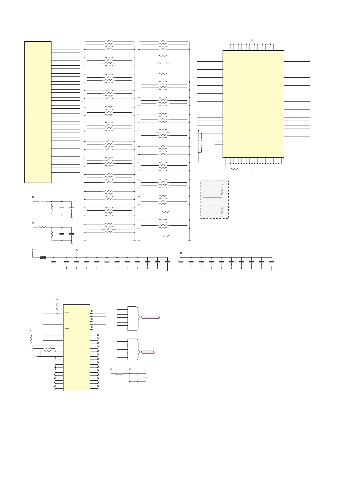
GRUNDIG Service Chassis G5
22R*4R1000
22R*4R1001
IC
MSD93F
FLH_3.3
IC1300
Chassisplatte / Chassis Board – RAM
100A
B_DDR3_A10
B_DDR3_A11
B_DDR3_A12
B_DDR3_A13
B_DDR3_A14
B_DDR3_CASZ
B_DDR3_RASZ
B_DDR3_WEZ
B_DDR3_ODT
B_DDR3_BA0
B_DDR3_BA1
B_DDR3_BA2
B_DDR3_RESETB
B_DDR3_CKE
MIU1
B_DDR3_DQ0
B_DDR3_DQ1
B_DDR3_DQ2
B_DDR3_DQ3
B_DDR3_DQ4
B_DDR3_DQ5
B_DDR3_DQ6
B_DDR3_DQ7
B_DDR3_DQ8
B_DDR3_DQ9
B_DDR3_DQ10
B_DDR3_DQ11
B_DDR3_DQ12
B_DDR3_DQ13
B_DDR3_DQ14
B_DDR3_DQ15
B_DDR3_DM0
B_DDR3_DM1
B_DDR3_MCLK
B_DDR3_MCLKZ
B_DDR3_DQS0
B_DDR3_DQS0B
B_DDR3_DQS1
B_DDR3_DQS1B
B_DDR3_CS0
1TW2
AVDD_DDR1
AVDD_DDR1
B_DDR3_A0
B_DDR3_A1
B_DDR3_A2
B_DDR3_A3
B_DDR3_A4
B_DDR3_A5
B_DDR3_A6
B_DDR3_A7
B_DDR3_A8
B_DDR3_A9
R1031
1K
R1033
1K
E11
F12
D10
B10
E15
B11
F14
C11
D14
A12
F16
D13
D15
C12
E13
B9
C8
D11
B8
A9
D16
A10
F10
E17
A20
A16
C19
C15
C20
C14
B21
B15
F18
D19
D17
E21
E19
D20
D18
F20
C16
D21
C13
B13
A19
C18
B18
C17
D12
B-MVREFDQ
R1032
1K
B-MVREFCA
R1034
1K
B_DDR3_A0
B_DDR3_A1
B_DDR3_A2
B_DDR3_A3
B_DDR3_A4
B_DDR3_A5
B_DDR3_A6
B_DDR3_A7
B_DDR3_A8
B_DDR3_A9
B_DDR3_A10
B_DDR3_A11
B_DDR3_A12
B_DDR3_A13
B_DDR3_A14
B_DDR3_CASZ
B_DDR3_RASZ
B_DDR3_WEZ
B_DDR3_ODT
B_DDR3_BA0
B_DDR3_BA1
B_DDR3_BA2
B_DDR3_RESET
B_DDR3_CKE
B_DDR3_DQL0
B_DDR3_DQL1
B_DDR3_DQL2
B_DDR3_DQL3
B_DDR3_DQL4
B_DDR3_DQL5
B_DDR3_DQL6
B_DDR3_DQL7
B_DDR3_DQU0
B_DDR3_DQU1
B_DDR3_DQU2
B_DDR3_DQU3
B_DDR3_DQU4
B_DDR3_DQU5
B_DDR3_DQU6
B_DDR3_DQU7
B_DDR3_DML
B_DDR3_DMU
B_DDR3_MCLK
B_DDR3_MCLKZ
B_DDR3_DQSL
B_DDR3_DQSLB
B_DDR3_DQSU
B_DDR3_DQSUB
B_DDR3_CS0
C1001
C1002
1NF
100NF
C1025
C1026
1NF
100NF
B_DDR3_A12 B-DDR3-A12
B_DDR3_BA1 B-DDR3-BA1
B_DDR3_A10 B-DDR3-A10
B_DDR3_CKE B-DDR3-CKE
B_DDR3_A6 B-DDR3-A6
B_DDR3_A4
B_DDR3_A11 B-DDR3-A11
B_DDR3_A8 B-DDR3-A8
B_DDR3_A14 B-DDR3-A14
B_DDR3_WEZ
B_DDR3_A3 B-DDR3-A3
22R*4R1002
22R*4R1005
B-DDR3-A4
22R*4R1007
22R*4R1009
B-DDR3-RASZB_DDR3_RASZ
B-DDR3-ODTB_DDR3_ODT
22R*4R1011
B-DDR3-A1B_DDR3_A1
22R*4R1013
B-DDR3-A9B_DDR3_A9
B-DDR3-A13B_DDR3_A13
22R*4R1015
B-DDR3-WEZ
B-DDR3-CS0B_DDR3_CS0
22R*4R1020
B-DDR3-A5B_DDR3_A5
B-DDR3-A7B_DDR3_A7
22R*4R1022
B-DDR3-A2B_DDR3_A2
B-DDR3-A0B_DDR3_A0
22R*4R1024
B-DDR3-CASZB_DDR3_CASZ
B-DDR3-BA0B_DDR3_BA0
22R*4R1028
B-DDR3-BA2B_DDR3_BA2
B_DDR3_DQL0 B-DDR3-DQL0
B_DDR3_DQL2 B-DDR3-DQL2
R1003
B-DDR3-DQL6B_DDR3_DQL6
22R
R1035
B-DDR3-DQL4B_DDR3_DQL4
22R
22R
R1004
B-DDR3-DQU5B_DDR3_DQU5
R1025
R1030
22R*4R1006
B-DDR3-DQU7
B-DDR3-DQU1
22R*4R1008
B-DDR3-DQU3B_DDR3_DQU3
22R*4R1010
B-DDR3-DQSLBB_DDR3_DQSLB
B-DDR3-DQSLB_DDR3_DQSL
22R*4R1012
B-DDR3-DQSUB
B-DDR3-DQSU
22R*4R1014
B-DDR3-DQU4B_DDR3_DQU4
22R*4R1018
B-DDR3-DQU6B_DDR3_DQU6
22R*4R1021
B-DDR3-DQL5
B-DDR3-DQL7
22R*4R1023
B-DDR3-DQL3B_DDR3_DQL3
B-DDR3-DQL1B_DDR3_DQL1
22R
22R*4R1027
B-DDR3-MCLKZ
B-DDR3-MCLK
22R
B_DDR3_DQU7
B_DDR3_DQU1
B_DDR3_DMU B-DDR3-DMU
B_DDR3_DQSUB
B_DDR3_DQSU
B_DDR3_DQU0 B-DDR3-DQU0
B_DDR3_DQU2 B-DDR3-DQU2
B_DDR3_DQL5
B_DDR3_DQL7
B_DDR3_DML B-DDR3-DML
B_DDR3_MCLKZ
B_DDR3_MCLK
B_DDR3_RESET B-DDR3-RESET
R1017
56R
B-DDR3-A0
B-DDR3-A1
B-DDR3-A2
B-DDR3-A3
B-DDR3-A4
B-DDR3-A5
B-DDR3-A6
B-DDR3-A7
B-DDR3-A8
B-DDR3-A9
B-DDR3-A10
B-DDR3-A11
B-DDR3-A12
B-DDR3-A13
B-DDR3-A14
B-DDR3-BA0
B-DDR3-BA1
B-DDR3-BA2
B-DDR3-RASZ
B-DDR3-CASZ
B-DDR3-WEZ
B-DDR3-ODT
B-DDR3-RESET
B-DDR3-CKE
B-DDR3-MCLK
B-DDR3-MCLKZ
R1016
56R
C1000
10NF
B-DDR3-RESET
B-DDR3-CKE
N3
P7
P3
N2
P8
P2
R8
R2
T8
R3
L7
R7
N7
T3
T7
M2
N8
M3
J3
K3
L3
K1
T2
K9
J7
K7
J1
J9
L1
L9
M7
AVDD_DDR1
R1026
1K
R1029
1K
R9
A0
A1
A2
A3
A4
A5
A6
A7
A8
A9
A10
A11
A12
A13
A14
BA0
BA1
BA2
/RAS
/CAS
/WE
ODT
/RESET
CKE
CK
/CK
NC1
NC2
NC3
NC4
NC5
ZQ
L8
T9
ZQ
VDD
VSS
R1
T1
R1019
240R
VDD
VSS
AVDD_DDR1
B2
H9
K2
G7
K8
N9
VDD
VDDD9VDD
VDD
VDD
VDDN1VDD
P9
VDDQ
VSSM1VSSM9VSSP1VSS
VSS
VSSG8VSSJ2VSS
VSS
J8
E1
A9
H2
VDDQ
VSS
B3
F1
G9
E9
VDDQ
VSSQ
G1
D2
VDDQ
VDDQ
VSSQ
VSSQ
F9
C9
E8
VSSQ
E2
A1
VDDQC1VDDQ
VDDQ
VREFDQ
VREFCA
VSSQ
VSSQ
D8
A8
VDDQ
DMU
DQSU
/DQSU
DQU0
DQU1
DQU2
DQU3
DQU4
DQU5
DQU6
DQU7
DML
DQSL
/DQSL
DQL0
DQL1
DQL2
DQL3
DQL4
DQL5
DQL6
DQL7
/CS
VSSQ
D1
VSSQB9VSSQ
B1
IC1000
K4B2G1646
D3
B-DDR3-DMU
C7
B-DDR3-DQSU
B7
B-DDR3-DQSUB
D7
B-DDR3-DQU0
C3
B-DDR3-DQU1
C8
B-DDR3-DQU2
C2
B-DDR3-DQU3
A7
B-DDR3-DQU4
A2
B-DDR3-DQU5
B8
B-DDR3-DQU6
A3
B-DDR3-DQU7
E7
B-DDR3-DML
F3
B-DDR3-DQSL
G3
B-DDR3-DQSLB
E3
B-DDR3-DQL0
F7
B-DDR3-DQL1
F2
B-DDR3-DQL2
F8
B-DDR3-DQL3
H3
B-DDR3-DQL4
H8
B-DDR3-DQL5
G2
B-DDR3-DQL6
H7
B-DDR3-DQL7
H1
B-MVREFDQ
M8
B-MVREFCA
L2
B-DDR3-CS0
L1000
60R3A
C1003
10uF
6.3V
C1004
10uF
6.3V
AVDD_DDR1VCC1.5V
C1005
100NF
C1006
100NF
C1007
100NF
C1008
100NF
C1009
100NF
C1010
100NF
Chassisplatte / Chassis Board – FLASH
FLH_3.3V
R1301
3.3K
R1302 NC
R1303 NC
V
F-WPZ
F-ALE
F-CEZ
F-WEZ
F-REZ
F-CLE
F-RBZ
TP158
R1300
NC
TC58NVG2S3ETA00
NAND FLASH
19
WP
17
ALE
9
CE
18
WE
8
RE
16
CLE
7
READY
38
LOCK/NC
12
VCC
37
VCCQ
13
VSS
36
VSS
45
NC45
46
NC46
47
NC47
NC4848NC27
40
NC40
39
NC39
35
NC35
NC1
NC2
NC3
NC4
NC5
NC6
NC10
NC11
NC14
NC15
NC20
NC21
NC22
NC23
NC24
NC25
NC26
NC28
NC33
NC34
29
F_D0
IO0
30
F_D1
IO1
31
F_D2
IO2
32
F_D3
IO3
41
F_D4
IO4
42
F_D5
IO5
43
F_D6
IO6
44
F_D7
IO7
1
2
3
4
5
6
10
11
14
15
20
21
22
VCC3V3
23
24
25
26
27
28
33
34
L1300
F_D0
F_D1
F_D2
F_D3
F_D4
F_D5
F_D6
F_D7
F-ALE
F-CLE
F-REZ
F-WEZ
F-WPZ
F-RBZ
F-CEZ
FLASHDATA
F_D0
F_D1
F_D2
F_D3
F_D4
F_D5
F_D6
F_D7
FLASH
F-ALE
F-CLE
F-REZ
F-WEZ
F-WPZ
F-RBZ
F-CEZ
FLH_3.3V
C1302
1uF
GND
C1011
100NF
FLASHDATA
C1300
100NF
FLASH
C1301
100NF
C1012
100NF
C1013
100NF
C1014
100NF
AVDD_DDR1
C1015
100NF
C1016
100NF
C1017
100NF
C1018
100NF
C1019
100NF
C1020
100NF
C1021
100NF
C1022
100NF
C1023
100NF
C1024
100NF
2 - 13
Page 60
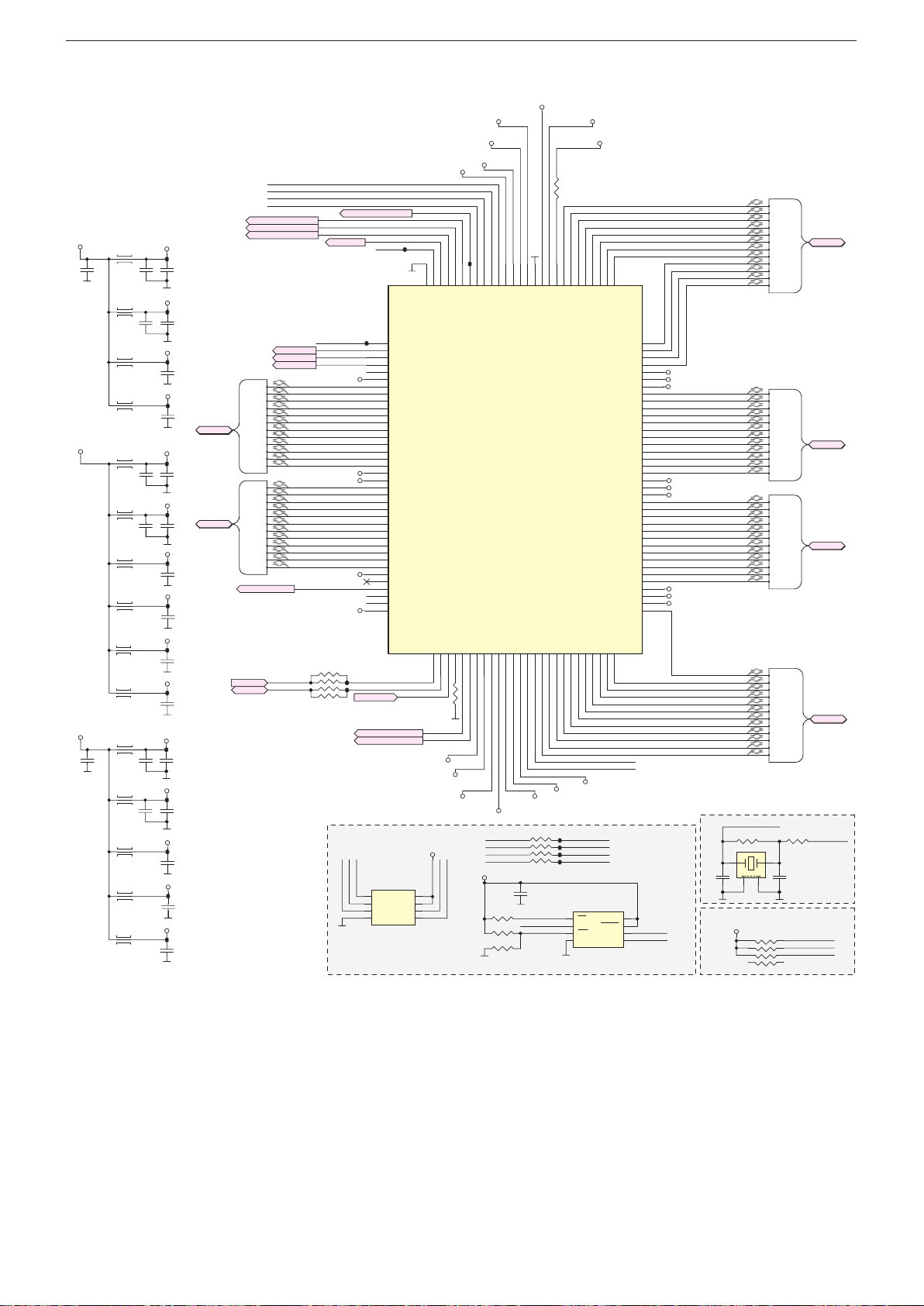
GRUNDIG Service Chassis G5
DVDD_DDR_DATA
VCC1.18V
Chassisplatte / Chassis Board – FRC
NORMAL 3.3V POWER
VCC3V3
C1400
10UF
CORE POWER
VCC1.8V
DDR POWER
C1415
10UF
L1400
L1401
L1402
L1403
L1404
L1405
L1406
L1407
L1408
L1409
L1410
L1411
L1412
L1413
L1414
AVDD_LVDSRX
TP159
C1402
C1401
100nF
10UF
FRC_VDDP
TP160
C1404
C1403
100nF
10UF
FRC_AVDD_MOD
TP161
C1405
100nF
FRC_AVDD_MPLL
TP162
C1406
100nF
DVDD
TP165
C1407
C1409
100nF
10UF
AVDDL_PREDRV
TP167
C1410
C1408
100nF
10UF
AVDD12_LVDSRX
TP168
C1411
100nF
FRC_AVDDL_MOD
TP169
C1412
100nF
DVDD_DDR_DATA
TP170
C1413
100nF
DVDD_DDR_CMD
TP171
C1414
100nF
AVDDIO_CMD0
TP172
C1416
C1418
100nF
10UF
AVDDIO_CMD1
TP173
C1417
C1420
100nF
10UF
AVDDIO_DATA0
TP174
C1419
100nF
AVDDIO_DATA1
TP176
C1421
100nF
AVDDIO_MCLK
TP178
C1423
100nF
LVDSB
LVDSB
LVDSA
LVDSA
B0_P
B0_N
B1_P
B1_N
B2_P
B2_N
BCK_P
BCK_N
B3_P
B3_N
B4_P
B4_N
A0_P
A0_N
A1_P
A1_N
A2_P
A2_N
ACK_P
ACK_N
A3_P
A3_N
A4_P
A4_N
FRC_BL_CTRL
I2C-SCL
I2C-SDA
SPI_DI
SPI_CK
SPI_CZ
SPI_DO
LDIM_U10_VSYNC
3D_SYNC_FRC_O
LDIM_U10_SPI_DI
FRC_DIM0
FRC_DIM1
FRC_DIM2
B0_P
B0_N
B1_P
B1_N
B2_P
B2_N
BCK_P
BCK_N
B3_P
B3_N
B4_P
B4_N
A0_P
A0_N
A1_P
A1_N
A2_P
A2_N
ACK_P
ACK_N
A3_P
A3_N
A4_P
A4_N
I2C-SCL
I2C-SDA
FRC-SCK
BRI_ADJ -> DIM2
VD_TX
FRC_DIM0
FRC_DIM1
FRC_DIM2
AVDD_LVDSRX
AVDD12_LVDSRX
AVDD_LVDSRX
AVDD12_LVDSRX
FRC_BL_CTRL
FRC_VDDP
R1401
47R
FRC_TCON_ON
TP166
TP175
TP177
URSA_RST
LDIM_U10_SPI_CS
LDIM_U10_SPI_DO
FRC SPI Flash
1
FRC_CSN
FRC_SDO
FRC_SPI_WPN
2
3
FRC-SCK
VD_RX
TP163
IC1400
1
PAD_GPIO[0]
2
PAD_DIM0
3
PAD_DIM1
4
PAD_DIM2
5
PAD_DIM3
6
AVDD_LVDSRX
7
PAD_RA0N
8
PAD_RA0P
9
PAD_RA1N
10
PAD_RA1P
11
PAD_RA2N
12
PAD_RA2P
13
PAD_RACKN
14
PAD_RACKP
15
PAD_RA3N
16
PAD_RA3P
17
PAD_RA4N
18
PAD_RA4P
19
AVDD12_LVDSRX/DVDD
20
AVDD_LVDSRX
21
PAD_RB0N
22
PAD_RB0P
23
PAD_RB1N
24
PAD_RB1P
25
PAD_RB2N
26
PAD_RB2P
27
PAD_RBCKN
28
PAD_RBCKP
29
PAD_RB3N
30
PAD_RB3P
31
PAD_RB4N
32
PAD_RB4P
33
AVDD12_LVDSRX/DVDD
34
PAD_SSPI2_DO
35
PAD_SSPI2_CZ
36
PAD_SSPI2_CK
37
PAD_SSPI2_DI
38
VDDP3_B
MST7438BB
URSA_RST
IC1401
NC
CE#
VDD
SO
HOLD#
WP#
SCK
VSS4SI
150mill
FRC_VDDP
FRC_TCON_ON
129
128
127
E-Pad
PAD_GPIO[1]
PAD_GPIO[2]
PAD_I2CS_SCL
PAD_I2CS_SDA40PAD_RESET
39
R1402
0R
DVDD
AVDDIO_CMD0
AVDDIO_CMD1
VCC3V3
8
FRC_SCK
FRC_SDI
7
6
5
AVDDIO_DATA1
AVDDIO_DATA0
DVDD
TP164
122
123
121
124
126
125
PAD_GPIO[6]
PAD_GPIO[5]
PAD_GPIO[3]
PAD_GPIO[4]
PAD_SPI_DO
22pF
DVDD45DVDD
PAD_SPI4_CK
PAD_SPI4_DI
PAD_TESTPIN
42
43
44
41
AVDDIO_MCLK
VCC3V3
120
118
117
119
116
DVDD
VDDP3_L
PAD_SPI_DI
PAD_SPI_CZ
PAD_SPI_CK
AVDDIO_DATA0
U8 128
AVDDIO_CMD046AVDDIO_CMD1
AVDDIO_CMD1/AVDDIO_MCLK
DVDD_DDR_CMD
AVDD_MPLL
48
49
51
47
50
DVDD_DDR_CMD
FRC_SDO
FRC_CSN
FRC_SCK
FRC_SDI
C1426
100nF
4.7K
R1407
R1408 4.7K
FRC_SPI_WPN
R1409
NC
*100MHz, No any VIA hole!
115
114
GND
AVDDIO_DATA1
PAD_XTALI
PAD_XTALO
53
52
R1406
47R
FRC_CSN
FRC_SDO
R1400
39K
111
113
112
DVDD
PAD_REXT
DVDD_DDR_DATA
PAD_D4M
PAD_D3M
PAD_D4P
54
56
55
FRC_AVDD_MPLL
DVDD
TP179
TP180
TP181
TP182
DVDD
FRC_AVDD_MOD
107
110
108
109
PAD_A0P
PAD_A1P
PAD_A1M
PAD_A0M
AVDDL_PREDRV
AVDDL_PREDRV
PAD_DCKM58PAD_DCKP59PAD_D2P
PAD_D3P
PAD_D2M
60
57
SPI_DO
SPI_CZ
SPI_CK
SPI_DI
IC1402
1
CS
2
DO
3
WP
GND4DI
W25Q80BVSSIG
104
105
106
PAD_A2P
PAD_A2M
AVDD_MOD
AVDDL_MOD
PAD_BCKP
PAD_BCKM
AVDD_MOD
PAD_CCKP
PAD_CCKM
AVDDL_MOD
AVDD_MOD
PAD_D1M
62
61
63
FRC_XTALI
FRC_XTALO
VCC
HOLD
CLK
200mill
103
PAD_ACKP
PAD_ACKM
PAD_A3P
PAD_A3M
PAD_A4P
PAD_A4M
DVDD
PAD_B0P
PAD_B0M
PAD_B1P
PAD_B1M
PAD_B2P
PAD_B2M
PAD_B3P
PAD_B3M
PAD_B4P
PAD_B4M
PAD_C0P
PAD_C0M
PAD_C1P
PAD_C1M
PAD_C2P
PAD_C2M
PAD_C3P
PAD_C3M
PAD_C4P
PAD_C4M
DVDD
PAD_D0P
PAD_D0M
PAD_D1P
64
8
7
6
5
102
101
100
99
98
97
96
95
94
93
92
91
90
89
88
87
86
85
84
83
82
81
80
79
78
77
76
75
74
73
72
71
70
69
68
67
66
65
FRC_SCK
FRC_SDI
A0x_P
A0x_N
A1x_P
A1x_N
A2x_P
A2x_N
ACKx_P
ACKx_N
A3x_P
A3x_N
A4x_P
A4x_N
FRC_AVDD_MOD
FRC_AVDDL_MOD
DVDD
B0x_P
B0x_N
B1x_P
B1x_N
B2x_P
B2x_N
BCKx_P
BCKx_N
B3x_P
B3x_N
B4x_P
B4x_N
AVDDL_PREDRV
FRC_AVDD_MOD
AVDDL_PREDRV
C0x_P
C0x_N
C1x_P
C1x_N
C2x_P
C2x_N
CCKx_P
CCKx_N
C3x_P
C3x_N
C4x_P
C4x_N
DVDD
FRC_AVDDL_MOD
FRC_AVDD_MOD
D0x_P
D0x_N
D1x_P
D1x_N
D2x_P
D2x_N
DCKx_P
DCKx_N
D3x_P
D3x_N
D4x_P
D4x_N
FRC XTAL
1 3
C1425
10pF
FRC Configuration (H/W Boot Strap)
VCC3V3
R1404
X1400
2
4
3
1
LVDSxA
LVDSxC
LVDSxD
FRC_XTALI
1M
4
R1410
4.7K
A0x_P
A0x_N
A1x_P
A1x_N
A2x_P
A2x_N
ACKx_P
ACKx_N
A3x_P
A3x_N
A4x_P
A4x_N
LVDSxB
B0x_P
B0x_N
B1x_P
B1x_N
B2x_P
B2x_N
BCKx_P
BCKx_N
B3x_P
B3x_N
B4x_P
B4x_N
C0x_P
C0x_N
C1x_P
C1x_N
C2x_P
C2x_N
CCKx_P
CCKx_N
C3x_P
C3x_N
C4x_P
C4x_N
D0x_P
D0x_N
D1x_P
D1x_N
D2x_P
D2x_N
DCKx_P
DCKx_N
D3x_P
D3x_N
D4x_P
D4x_N
R1405
1k
C1424
10pF
5
6
72
8
LVDSxA
LVDSxB
LVDSxC
LVDSxD
FRC_XTALO
24MHz
CL=8pF
2.0*1.6
VD_TX
VD_RX
FRC-SCK
2 - 14
Page 61
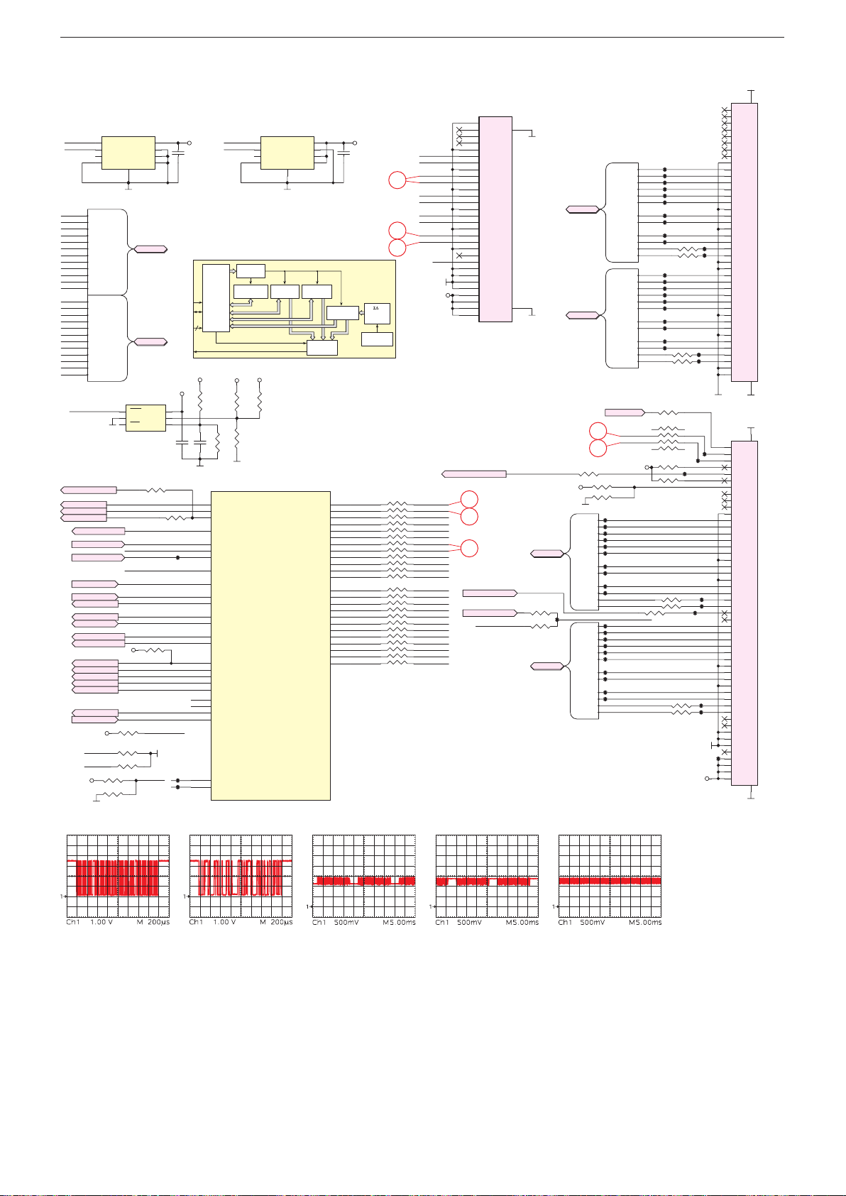
GRUNDIG Service Chassis G5
MSD93F1TW2
LVDS for FHD/100Hz CellsLVDS for FHD Cells
ALER
9
0
* ( )
Chassisplatte / Chassis Board – Scaler-SOC/LVDS
42
S100
41
Cabinet TEMP SOC TEMP (optional)
IC102 AT30TS74
1
I2C-SDA
SDA
SCL
ALERT
GND
1
2
BRI_ADJ
PCM_PWR_CTL
3D_SYNC_G7_O
VCC3V3-ST
R128
R130
R131
R133
4.7K
VCC
e-PAD
9
LVDSA
LVDSA
LVDSB
LVDSB
IC101 NC
RST
VSS
MR3VCC2
R114 0R
PM_PWM
KEY_ADC
HW_ID
HDMI_DETECT
POWER_DROP
WOWL
UART-RX
UART-TX
G7_TCON_ON
PD-AMP
R136
WLAN_EN
POWER_SW
EDID_WP
USB_CTRL
G7_BL_ON
MUTE_AMP
SC-HSYNC
4.7K
4.7KI2C-SCL
4.7K
HW_ID
A0
A1
A2
VCC1
RSTIN
I2C-SCL
I2C-SDA
10K
POWER_SW
2
I2C-SCL
3
4
A0_P
A0_P
A0_N
A0_N
A1_P
A1_P
A1_N
A1_N
A2_P
A2_P
A2_N
A2_N
ACK_P
ACK_P
ACK_N
ACK_N
A3_P
A3_P
A3_N
A3_N
A4_P
A4_P
A4_N
A4_N
B0_P
B0_P
B0_N
B0_N
B1_P
B1_P
B1_N
B1_N
B2_P
B2_P
B2_N
B2_N
BCK_P
BCK_P
BCK_N
BCK_N
B3_P
B3_P
B3_N
B3_N
B4_P
B4_P
B4_N
B4_N
POWER_DROP
LDIM_G7_SPI_CS
BRI_ADJ
PCM_PWR_CTL
3D_SYNC_G7_O
PM_PWM
KEY_ADC
HDMI_DETECT
WOWL
UART-RX
UART-TX
I2C-SCL
I2C-SDA
G7_TCON_ON
PD-AMP
WLAN_EN
POWER_SW
EDID_WP
USB_CTRL
G7_BL_ON
MUTE_AMP
SC-HSYNC
VCC3V3-ST
I2C-SDA
VCC3V3
R132 NC
8
7
6
5
A
VCC3V3
6
5
4
R135
0R
TP200
VCC3V3-ST
TP55
TP56
VCC3V3
C102
100NF
SCL
SDA
2-0
T
+5V2_ST
C100NCC101
3
G21
G19
G20
E9
C4
A4
B4
D6
A2
E7
E8
P17
P16
H17
H16
B3
B1
B2
D8
G4
B7
A7
D7
F8
T3
T1
I2C-SDA
I2C-SCL
Pointer
Register
C/SMBus
Configuration
2
I
Interface
Register
Control
and
Logic
V_AUDIO
R105
R100
NC
NC
R104
NC
R106
NC
NC
IC100D
PWM0
PWM1
PWM2
PWM_PM
SAR0
SAR1
SAR2
SAR5
PM_SPI_DI
DDCA_CK/UART0_RX
DDCA_DA/UART0_TX
DDCR_CK
DDCR_DA
UART_RX2
UART_TX2
GPIO_PM1/PM_UART_TX
GPIO_PM4
GPIO_PM5/PM_UART_RX
GPIO_PM7
GPIO_PM0
VID0
VID1
GPIO_PM10
SAR3/PM_SPI_CZ
W_I2CS_SDA
W_I2CS_SCL
IC103NC
1
2
3
4
+12V
PWMSARSPI
SDA
SCL
ALERT
GND
T
R101
NC
HIGH
Register
9
Limit
S301
1
P1
2
3
VESA
3D_SYNC_PANEL_O
4
5
6
7
8
9
10
11
12
13
14
15
16
17
18
19
20
21
22
23
24
25
26
27
28
29
30
18
19
20
3D_EN/ SC_BL_EN
3D_SYNC_FRC_O
8
VCC
A0
A1
e-PAD
A2
VCC3V3
7
C103
6
NC
5
C9x0 sserdA09x0 sserdA
20
18
19
A3x_P
A3x_N
ACKx_P
ACKx_N
A2x_P
A2x_N
A1x_P
A1x_N
A0x_P
A0x_N
AT30TS74
T
Limit
LOW
Register
Comparator
ACKP
ACKM
LVDS
BCKP
BCKM
GPIO
Digital
A0P
A0M
A1P
A1M
A2P
A2M
A3P
A3M
A4P
A4M
B0P
B0M
B1P
B1M
B2P
B2M
B3P
B3M
B4P
B4M
Temperature
Register
R19
R20
R21
T19
T21
T20
U19
U20
V19
V20
V21
W19
K21
K20
L19
L20
M19
M20
M21
N19
N21
N20
P19
P20
A0_P
A0_N
A1_P
A1_N
A2_P
A2_N
ACK_P
ACK_N
A3_P
A3_N
A4_P
A4_N
B0_P
B0_N
B1_P
B1_N
B2_P
B2_N
BCK_P
BCK_N
B3_P
B3_N
B4_P
B4_N
Converter
Temperature
A/D
Sensor
4*0R R110
4*0R R111
4*0R R113
4*0R R118
4*0R R119
4*0R R120
PANEL_PWR
A0x_P
A0x_N
A1x_P
A1x_N
A2x_P
A2x_N
ACKx_P
ACKx_N
A3x_P
A3x_N
A4x_P
A4x_N
B0x_P
B0x_N
B1x_P
B1x_N
B2x_P
B2x_N
BCKx_P
BCKx_N
B3x_P
B3x_N
B4x_P
B4x_N
P2
P31
P3
P4
P5
P6
P7
P8
P9
P10
P11
P12
P13
P14
P15
P16
P17
P18
P19
P20
P21
P22
P23
P24
P25
P26
P27
P28
P29
P32
P30
3D_SYNC_G7_O
31
LVDS for HD Cells
32
3D_SYNC_PANEL_O
VCC3V3
LVDSxA
47R
R123
TP41
47R
R125
LVDSxB
LVDSxB
LVDSxC
LVDSxC
LVDSxD
LVDSxD
LVDSxA
A0x_N
A1x_N
A2x_N
ACKx_P
ACKx_N
A3x_N
A4x_N
B0x_N
B1x_N
B2x_N
BCKx_P
BCKx_N
B3x_N
B4x_N
R129
0R
A0x_P
A1x_P
A2x_P
A3x_P
A4x_P
B0x_P
B1x_P
B2x_P
B3x_P
B4x_P
C0x_P
C0x_N
C1x_P
C1x_N
C2x_P
C2x_N
CCKx_P
CCKx_N
C3x_P
C3x_N
C4x_P
C4x_N
D0x_P
D0x_N
D1x_P
D1x_N
D2x_P
D2x_N
DCKx_P
DCKx_N
D3x_P
D3x_N
D4x_P
D4x_N
URSA_RST
9
I2C-SCL
I2C-SDA
10
VCC3V3
R115
NC
R117
NC
A0x_P
TP28
TP29
A0x_N
TP30
A1x_P
TP31
A1x_N
A2x_P
TP32
TP33
A2x_N
ACKx_P
TP34
TP35
ACKx_N
TP36
A3x_P
A3x_N
TP37
A4x_P
A4x_N
3D_EN/ SC_BL_EN
3D_SYNC_PANEL_I
TP42
B0x_P
TP43
B0x_N
TP44
B1x_P
TP45
B1x_N
TP46
B2x_P
TP47
B2x_N
TP48
BCKx_P
TP49
BCKx_N
TP50
B3x_P
TP51
B3x_N
B4x_P
B4x_N
TP1
C0x_P
TP2
C0x_N
TP3
C1x_P
TP4
C1x_N
TP5
C2x_P
TP6
C2x_N
TP7
CCKx_P
TP8
CCKx_N
TP9
C3x_P
TP10
C3x_N
R102
C4x_P
R103 0R
C4x_N
TP13
D0x_P
TP14
D0x_N
TP15
D1x_P
TP16
D1x_N
TP17
D2x_P
TP18
D2x_N
TP19
TP20
TP21
D3x_P
TP22
D3x_N
D4x_P
R107
D4x_N
R108
R134
0R
R109
47R*4
R112
3D_FORMAT0
4.7K
R116
3D_FORMAT1
4.7K
R121 0R
R122 0R
R124
0R
R126 0R
R127 0R
PANEL_PWR P1
TP27
0R
0R
VESA
40
39
38
37
36
35
34
33
32
31
30
29
28
27
26
25
24
23
22
21
20
0R
TP11
19
18
TP12
17
16
15
14
13
12
11
10
9
8
7
6
5
4
TP23
3
TP24
2
1
51
50
TP25
49
TP26
48
47
46
45
44
43
42
41
40
39
38
37
36
35
34
33
32
31
30
29
28
TP38
27
TP39
26
TP40
25
24
23
22
21
20
19
18
17
16
15
14
13
12
TP52
11
TP53
10
9
8
7
6
5
TP54
4
3
2
1
S101
P41
P40
GND
P39
P38
P37
P36
P35
P34
P33
P32
P31
P30
P29
P28
P27
P26
P25
P24
P23
P22
P21
P20
P19
P18
P17
P16
P15
P14
P13
P12
P11
P10
P9
P8
P7
P6
P5
P4
P3
P2
GND
P1
43
52
P51
P50
GND
P49
P48
P47
P46
P45
P44
P43
P42
P41
P40
P39
P38
P37
P36
P35
P34
P33
P32
P31
P30
P29
P28
P27
P26
P25
P24
P23
P22
P21
P20
P19
P18
P17
P16
P15
P14
P13
P12
P11
P10
P9
P8
P7
P6
P5
P4
P3
P2
GND
53
2 - 15
Page 62
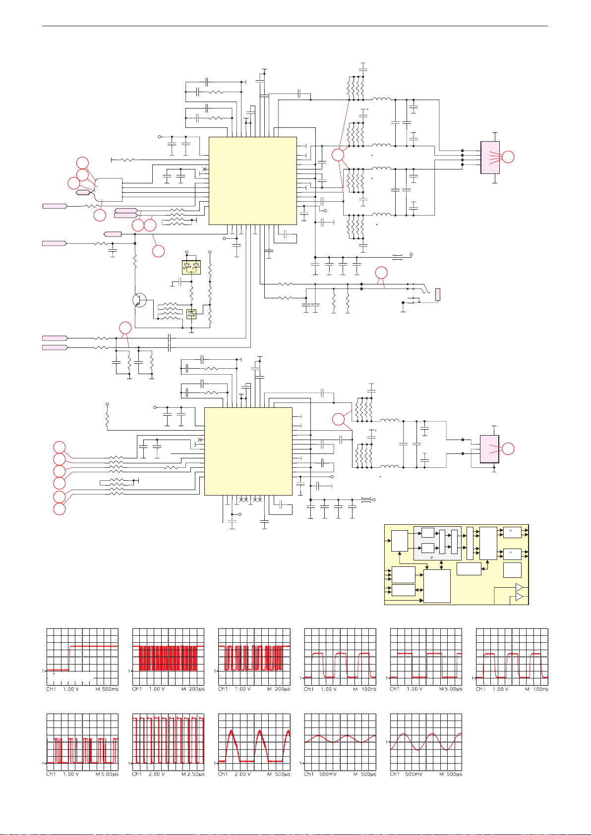
GRUNDIG Service Chassis G5
C802
LRCLK
HPL_OUT
T
HPR_INHPL_IN
8
9
0
¡ ™ £
≤ ∞ § ≥ •
Chassisplatte – Verstärker / Chassis Board – Amplifier
PD-AMP
MUTE_AMP
HP_Audio-R
HP_Audio-L
21
22
23
24
10
9
21
22
23
I2S
PD-AMP
MUTE_AMP
HP_Audio-R
HP_Audio-L
I2S_OUT-MCK
I2S_OUT-WS
I2S_OUT-BCK
I2S_OUT-SD
I2C-SDA
I2C-SCL
R805
1k
I2S
I2S_OUT-MCK
I2S_OUT-WS
I2S_OUT-BCK
I2S_OUT-SD
24
MUTE
R812
10K
R824
0R
R837
0R
C846
VCC3V3
4
3
1
1
3
4
R836 100R
R802
4.7K
I2C-SDA
I2C-SCL
1uF
C828
27
R826
NC
NC
R829
4.7K
R830 100R
VCC3V3
I2S_OUT-MCK
I2S_OUT-WS
I2S_OUT-BCK
I2S_OUT-SD
PD-AMPX
I2C-SDA
I2C-SCL
10 9
TP95
R803
100R
T800
32
BC847B
C847
NC
VCC3V3
C864
10uF
6.3V
5
6
72
8
8
72
6
5
C878
10uF
35V
C835
10uF
R807
100R
35V
R806
100R
330pF50V
R804
100R
L800
NR 6045T 220M
C810
330pF50V
L801
NR 6045T 220M
L802
NR 6045T 220M
C824
330pF50V
R808
100R
C838
330pF50V
28
TP96
TP97
C856
330pF50V
R810
NC/100R
NR 6045T 220M
C860
330pF50V
R817
NC/100R
4A
30R
V_AUDIO
L807
SDIN
MCLK
SCLK
SDA
SCL
C811
NC
C821
NC
L803
NR 6045T 220M
30R
L804
4A
HPR
HPL
TP98
L805
L806
NR 6045T 220M
Serial
Audio
Port
Sample Rage
Autodetect
and PLL
Control
Terminal Control
C809
220nF/50V
C812
NC
C813
220nF/50V
C818
220nF/50V
C822
NC
C825
220nF/50V
V_AUDIO
S801
3
2
4
1
PHONE_JACK_PJ-3600
C862
C863
NC
NC
L
R
Serial
C859
220nF/50V
C867
220nF/50V
7 BQ
7 BQ
DAP
Microcontroller
Based
System
Control
SP_LEFT+
SP_LEFTSP_RIGHT-
SP_RIGHT+
SUBW+
SUBW-
VOLUME
TP90
TP91
TP92
TP93
TP99
TP100
DRC
SRC
Click and Pop
Control
TAS5739
S800
1
2
3
4
TO Speaker
S802
3
P3
2
P2
1
P1
TO Woofer
Order
Noise
Shaper
PWM
5
GND
P1
P2
26
P3
P4
GND
6
5
GND
26
GND
4
OUT_A
2HB
th
4
and
FETOut
2HB
FETOut
Protection
Logic
OUT_B
OUT_C
OUT_D
HPR_OU
12
25
C837
100nF
R816->0R for 12,5V PSU
12
11
VR_ANA
/RESET
25
MUTE
11
10
9
VR_ANA
PLL_FLTP
PLL_FLTM
/RESET
STEST
DVDD27DVSS
26
28
C853
100nF
8
9
10
AVSS
PLL_FLTP
PLL_FLTM
STEST26DVDD27DVSS
28
C881
100nF
C803
2.2n
C807
100nF
6
7
8
GND
AVSS
AGND
HPR_IN
HPL_IN30HP_GND31HPR_OUT32HPL_OUT
29
C850
2.2n
5
7
6
GND
VREG
AGND
HPR_IN29HPL_IN30HP_GND31HPR_OUT32HPL_OUT
VCC3V3
5
VREG
4
SSTIMER
33
C804
1UF 25V
4
SSTIMER
GVDD_OUT
33
C851
1UF25V
3
BST_A
GVDD_OUT
HPVSS34CPN35CPP
C880
1UF 25V
2
3
BST_A
PVDD_A
PGND_AB
PGND_CD
HPVSS
CPN35CPP
34
C839
10uF 6.3V
R811
R815
2
1
OUT_A
PVDD_A
PGND_AB
OUT_B
PVDD_B
PVDD_C
OUT_C
PGND_CD
OUT_D
PVDD_D
HPVDD
C879
36
1UF 25V
1
TAS5739
EPAD
OUT_A
OUT_B
PVDD_B
BST_B
BST_C
PVDD_C
OUT_C
OUT_D
PVDD_D
BST_D
HPVDD
C836
36
1UF 25V
TAS5739
EPAD
BST_B
BST_C
BST_D
C841
10nF
C805
10R
10R
49
48
47
46
45
44
43
42
41
40
39
38
37
33nF 50V
49
48
47
46
45
44
43
42
41
40
39
38
37
C827
1UF
10uF
35V
C870
1UF
10uF
35V
TP94
C855
33nF 50V
C866
33nF 50V
C868
33nF 50V
TP101
C876C875
10uF
35V
C816
33nF 50V
C820
33nF 50V
C823
C826
100nF
C833C832
10uF
35V
C840
10nF
C869
100nF
33nF 50V
VCC3V3
C861
C877
10uF
35V
25
C834
10uF
35V
R8131KR814
1K
25
33nF 50V
VCC3V3
C800 4.7nF
C801
R800
470R
47NF
C806 4.7nF
C808
R801
470R
47NF
C815
100nF
C817
100nF
8
72
6
5
1
2
3
R818
10K
3 2
AP432SRG-7
C849
47NF
C854
47NF
C858
100nF
IC800
13
14
15
16
17
18
19
20
21
22
23
24
MUTE
VCC3V3
V_AUDIO
1
IC801
C848
4.7nF
R827 470R
C852
4.7nF
R828 470R
IC802
13
AVDD
14
A0/FAULT
15
MCLK
16
NC
17
DVSS
18
VR_DIG
19
/PDN
20
LRCLK
21
SCLK
22
SDIN
23
SDA
24
SCL
AVDD
A0/FAULT
MCLK
NC
DVSS
VR_DIG
/PDN
LRCLK
SCLK
SDIN
SDA
SCL
20KR820 20KR816
R8232.7K%1
C814
10uF
6.3V
C819
10uF
6.3V
R809
1
3
4
100R
+5V2_ST
8
D800
BAT54CW
C843
10UF
1
R821
1
8
72
3
6
5
4
10K
1uFC844
1uF
C845
R825
NC
C857
10uF
6.3V
C865
100nF
PD-AMPX
R831
0R
Power on (trigger: +12V)
2 - 16
Page 63
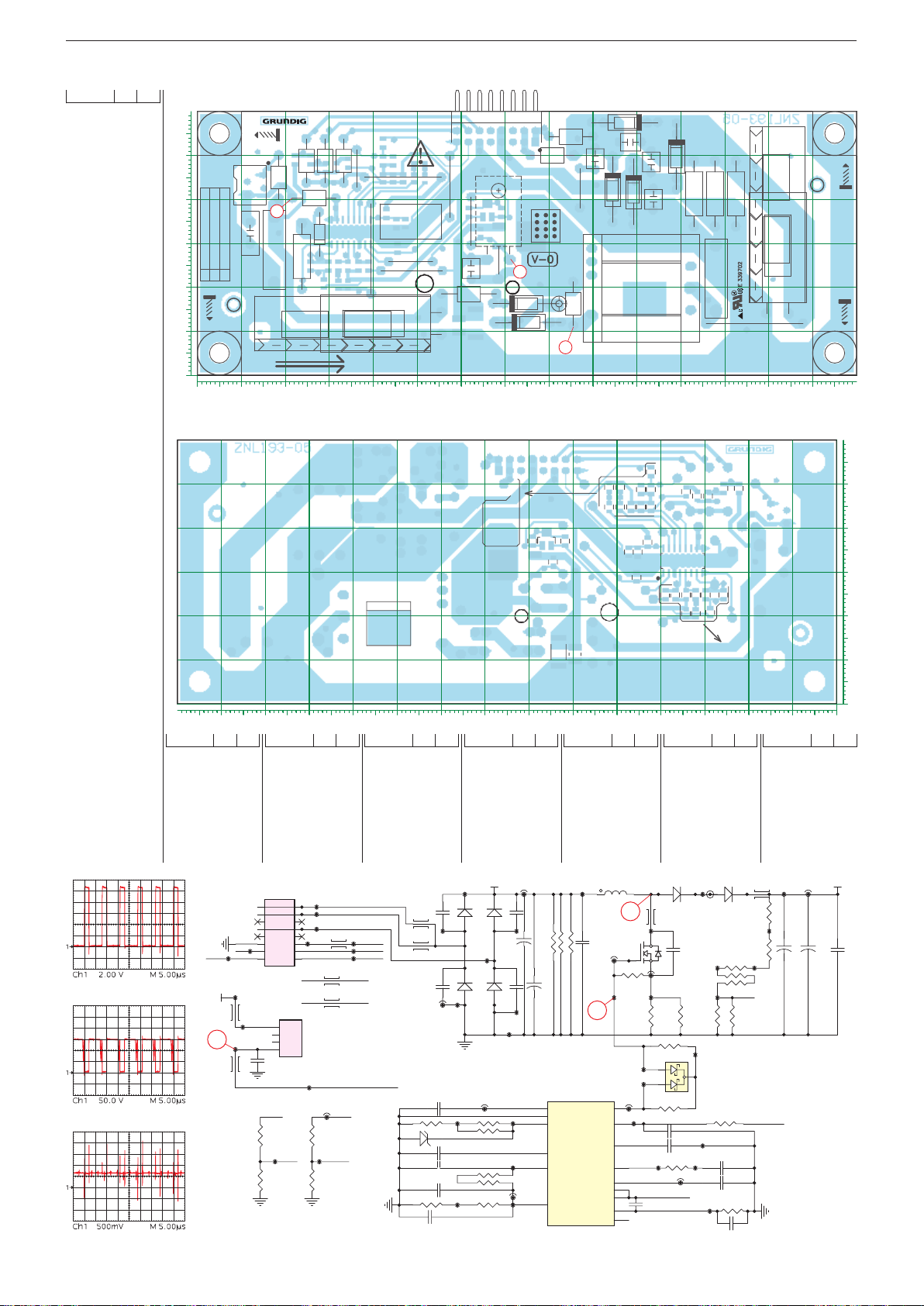
GRUNDIG Service Chassis G5
10
20
30
40
50
Y
0102030405060708090 100 110 120 130 140
X
10
20
30
40
50
Y
0102030405060708090100110120130140
X
VLED
VIN
33K+2.2K Rlower=3.3K==>3.3K+0R
VLE
330NF
C2012
D2011
D2012
1
2
3
LED-Konverter / Converter ZNL193-05 Ansicht von der Bestückungsseite / View of Component Side
POS. X Y
C2000 T 132 14
C2001 T 56 12
C2002 B 37 25
C2003 T 132 14
C2004 B 42 49
C2005 B 47 45
C2006 B 45 35
C2007 B 49 49
C2008 T 99 53
C2009 B 34 25
C2010 B 34 21
C2011 T 118 22
C2012 T 18 29
C2013 T 56 12
C2014 T 103 49
C2015 B 46 29
C2016 T 91 49
C2017 T 104 40
C2018 T 62 24
C2019 T 12 32
D2000 T 75 16
D2001 T 97 57
D2002 T 109 50
D2003 T 28 32
D2004 T 95 42
D2005 T 75 12
D2006 B 66 38
D2007 T 99 42
Ansicht von der Lötseite / View of Solder Side
D2009 T 97 58
D2010 T 109 50
D2011 T 75 16
D2012 T 75 12
D2013 T 95 42
D2014 T 99 42
0
MH1
1
S2001
C2019
VLED=144V ILED=330mA
VLED=208V ILED=270mA
VLED=270V ILED=310mA
43
49
55
C2012
POZA1
C2001
MH2
L2005
3
L2009
L2006
R2029
L2008
L2007
J2005
J2006
D2003
RTV
AREA
C2013
RTV
J2009
AREA
TRANSPORT LINE
FID3
ER2000 T 82 16
IC2000 B 35 33
J2001 T 62 35
J2002 T 49 24
J2003 T 57 43
J2004 T 47 45
J2005 T 36 47
J2006 T 40 29
J2007 T 87 43
J2009 T 49 26
J2012 T 127 12
L2001 T 86 16
L2002 T 101 20
L2003 T 85 54
L2004 T 81 50
L2005 T 19 45
L2006 T 27 40
L2007 T 33 49
L2008 T 29 49
L2009 T 25 49
L2010 T 62 19
R2000 B 22 49
R2001 B 26 49
R2002 B 29 47
R2003 B 34 48
R2004 B 65 32
R2005 B 29 21
R2006 B 26 25
R2007 B 30 25
R2008 B 32 25
R2009 B 32 21
R2010 B 63 12
POS. X Y POS. X Y POS. X Y POS. X Y POS. X Y POS. X Y POS. X Y
R2011 B 52 49
R2012 B 52 45
R2013 T 123 41
R2014 B 42 45
R2015 B 45 45
R2016 T 118 41
R2017 B 62 37
R2018 B 69 37
R2019 B 32 47
R2020 B 60 11
GND
FID2
R2021 T 113 41
R2022 B 39 25
R2023 B 42 53
R2024 B 43 37
R2027 B 45 49
R2028 B 47 35
R2029 T 24 27
R2031 B 49 45
S2000 T 68 54
S2001 T 13 43
PSU
TP4
12
Panel
S2001
EN
LED_Winding_2
LED_Winding_1
TP3
TP8
LED_Winding_3
DIM2
DIM1
TP28
DIM0
DIM1
L2008
DIM0
L2007
P1
P2
P3
P4
TP24
J2004
JUMPER
R2024
TP35
R2028
1 2
3 4
5 6
7 8
9 10
11
BL
TP10
12V
D
3
L2006
13 14
TP12
15 16
S2000
TP36
L2005
TP22
1
2
3
TP42
4
C2019 (ZNL-193-05): C-PEM 22NF J 100V R:5 AP
C2019 (ZNL-193-05): C-PEM 22NF J 250V R:5 AP
GND
BL
R2023
TP34
R2027
GND GND
L2009
PWM1
PWM1
LED_Cur_Return
PWM1
PWM
TP5
TP9
TP11
BARCODE
T2000 B 74 32
T2001 T 69 22
TP1 B 127 48
TP2 B 74 13
TP3 B 74 51
TP4 B 79 56
TP5 B 31 44
TP6 B 78 21
TP7 B 24 51
TP8 B 71 49
PWM1
GND
J2004
BARCODE
J2002
R2005
D2003
R2011
PSU
DIM2
DIM1
DIM0
BL
12V
J2003
J2001
C2018
+
L2010
55''
55''
TP9 B 30 56
TP10 B 45 54
TP11 B 35 56
TP12 B 50 29
TP13 B 100 44
TP15 B 50 13
TP16 B 27 46
TP17 B 28 49
TP18 B 116 17
TP20 B 59 30
TP1
C2008
D2009
L2003
L2004
C2015
C2006
C2009
C2010
D2001
TP29
C2016
D2013
TP38
J2007
GND
1UF 50V
R2006
R2007
TP43
1NF50V
50V
1UF
R2009
1UF 50V
TP55
3.3K
1UF 50VC2020
Current Level
43"= 340mA ==> Rupper=35,2K ==>
S2000
LED W2
GND
T2001
1
L2004
LED W1
LED W3
14/15
1
D2011
ER2000
D2000
D2005
D2012
R2023
R2011
R2027
C2007
C2004
D2006
R2018
R2012
R2014
R2031
R2015
C2005
J2012 J2000
C2014
D2010
D2002
+
TP30
C2000
47UF
TP13
160V
C2003
+
C2017
450V
D2014
D2007D2004
47UF
TP41
TP23
PWM
12V
TP44
TP49
JUMPER
J2006
TP56
IC2000
1
3
7
16
5
15
FAN73402MX
J2003
R2012
JUMPER
0R
82K82K
82K
2.2KR2008
33K
55''
L2003
D2001
C2016
J2007
D2013
2
31
L2001
6
2
R2017
R2004
R2010
R2020
TP21 B 40 47
TP22 B 16 47
TP23 B 65 47
TP24 B 31 38
TP25 B 68 39
TP26 B 67 31
TP27 B 56 29
TP28 B 27 56
TP29 B 87 54
TP30 B 91 43
TP18
9
R2016
R2013
R2021
C2011
330NF
450V
1
DRV
VCC
GND
RT
OVP
BDIM
REF
CMP
ENA
DRAIN
DRAIN
ADIM
SENSE
FAULT
D2009
D2004
D2007
R2024
C2006
R2028
C2015
6
L2002
2
T2000
FDPF5N50NZF
T2001
FQN1N50C
J2001
1
1
R2004
TP20
TP37
R2010
TP26
TP27
J2009
2
JUMPER
4
TP31
CS
13
OVP
14
12
EN
9
10
LED_Cur_Return
8
C2019 (ZNL-193-07):
6
C-PEM 22NF J 100V R:5 AP
C-PEM 22NF J 250V R:5 AP
C2008
23
23
C2002
C2005
55''
D2002
C2014
C2017
L2002
D2014
R2003
IC2000
1
TP31 B 37 27
TP34 B 40 50
TP35 B 41 36
TP36 B 19 32
TP37 B 71 36
TP38 B 125 10
TP39 B 37 39
TP40 B 49 47
TP41 B 52 9
TP42 B 19 43
TP2
D2005
L2001
TP6
C2018
R2002
J2002
R2019
R2003
ISENSE
R2014
R2020
R2018
TP25
D2006
1
3
2
BAT54C
R2017
470PF50V
1NF 50V
R2031
TP39
TP40
J2005
JUMPER
ZNL193-05
C2003
D2010
R2016
R2021
R2013
RTV
AREA
C2000
55''
55''
55''
RTV
AREA
C2011
10
9
8
R2019
ER2000
TP21
TP48
CEM1
R2000
R2001
R2002
R2022
C2009
C2002
C2010
D2000
R2000
R2001
OVP
R2015
OVP Level = Vomax * 1,3
Pin OVP Level =3V
43"= 155*1,3=201,5V ==> 6,8K//68KK ==> 197V
49"= 227*1,3=295V ==> 4,7K//33K ==> 296V
55"= 290*1,3=377V ==> 3,3K//NC==> 367V
330RR2022
C2007
4.7NF 50V
C2004
1NF 50V
R2029
TP54
C2021
+
J2012
MH3
FID4
R2006
R2007
R2008
FID1
R2009
R2005
TP43 B 28 23
TP44 B 26 27
TP48 B 64 51
TP49 B 34 27
TP50 B 32 23
TP54 B 24 22
TP55 B 52 47
TP56 B 37 19
L2010
TP15
TP7
C2013
+
250V
TP17TP16
47UF
ISENSE
GND
MH4
POZA2
+
C2001
+
450V
47UF
0
450V
2 - 17
Page 64
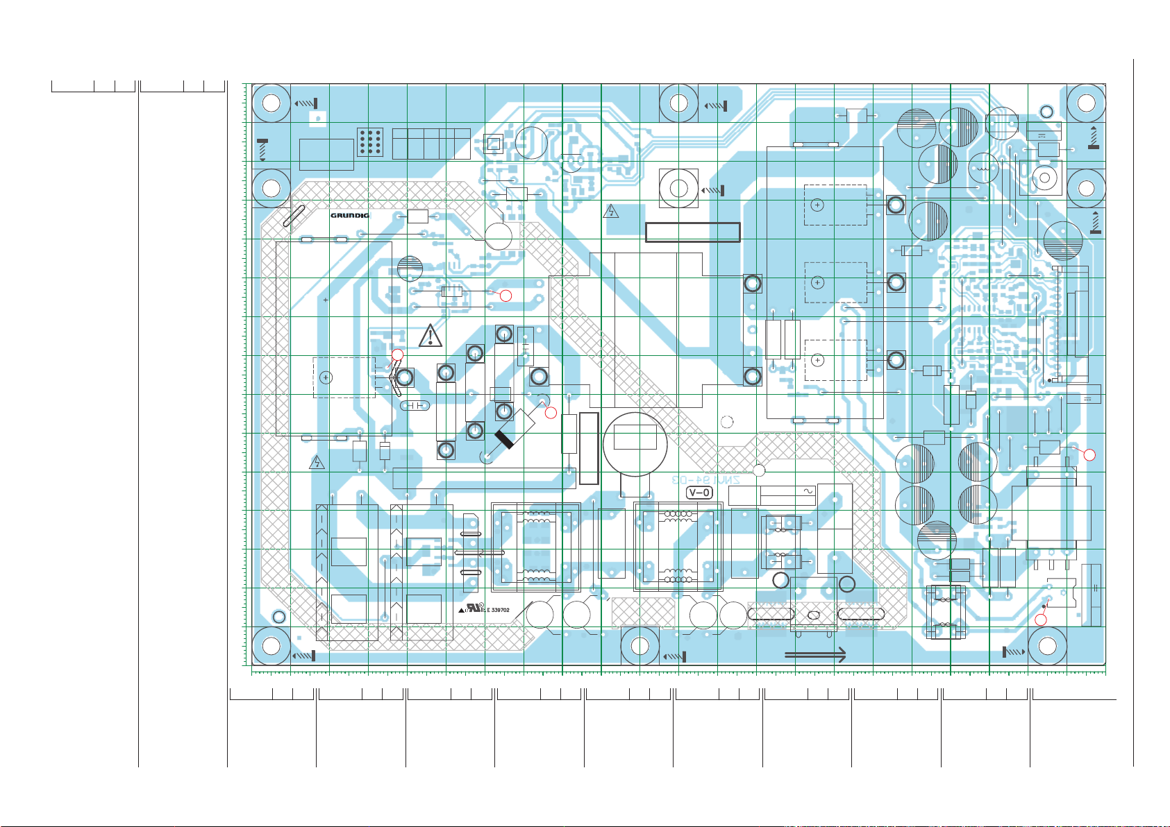
100
110
120
130
140
150
0
X
Netzteil / Power Supply ZNV194-03 Ansicht von der Bestückungsseite / View of Component Side
GRUNDIG Service Chassis G5
POS. X Y POS. X Y
C2000 T 44 44
C2001 T 25 44
C2002 T 71 82
C2003 B 137 75
C2004 B 143 71
C2005 T 182 139
C2006 T 177 129
C2007 B 167 139
C2008 T 209 110
C2009 B 210 84
C2010 T 42 67
C2011 B 46 101
C2012 B 57 102
C2013 B 52 92
C2014 T 91 13
C2015 T 81 13
C2016 T 41 102
C2017 T 93 32
C2018 B 80 138
C2019 B 78 126
C2020 T 59 116
C2021 T 127 32
C2022 T 117 13
C2023 T 110 13
C2024 B 139 71
C2025 T 174 115
C2026 B 88 127
2 - 18
C2027 T 171 139
C2500 B 187 35
C2501 B 190 37
C2502 B 187 40
C2503 T 187 42
C2504 T 187 53
C2505 B 194 97
C2506 B 188 82
C2507 T 171 41
C2508 T 177 32
C2509 T 171 52
C2510 B 193 37
C2511 B 196 36
C2512 B 193 77
C2513 B 198 99
C2514 B 196 87
C2515 B 194 87
C2516 B 178 104
C2517 B 188 105
C2518 B 185 82
C2520 B 190 101
C2521 B 195 90
D2000 T 166 119
D2001 B 35 84
D2002 T 166 99
D2003 T 68 61
D2004 B 37 93
D2005 T 34 55
D2006 T 52 97
D2007 B 45 27
D2008 B 40 29
D2009 B 84 124
D2010 B 96 129
D2011 B 66 136
D2012 T 166 79
D2013 T 170 107
D2500 T 182 26
D2501 T 182 23
D2502 B 185 29
D2503 B 180 29
D2505 B 198 79
D2506 T 185 69
D2507 T 175 76
D2508 B 183 28
D2509 B 187 109
DB2000 T 57 29
EL2000 T 129 98
EL2001 T 166 99
EL2002 T 166 79
EL2003 T 166 119
EL2004 T 39 74
EL2005 T 129 74
EL2007 T 50 76
EL2008 T 50 56
EL2009 T 58 61
EL2010 T 58 81
EL2011 T 65 66
EL2012 T 65 86
EL2013 T 74 74
FS2000 T 142 51
FS2001 T 194 145
FS2002 T 193 140
HS2000 T 145 99
HS2001 T 19 84
IC2000 B 52 100
IC2001 B 68 111
IC2002 B 83 137
IC2003 T 82 130
IC2500 B 187 89
J2000 T 52 93
J2001 T 99 44
J2002 T 178 123
J2003 T 88 31
J2004 T 36 111
J2005 T 34 20
J2006 T 64 125
J2007 T 180 121
J2008 T 199 101
J2009 T 197 123
J2010 T 195 125
J2011 T 193 120
J2012 T 157 71
J2500 T 165 92
J2501 T 183 89
J2502 T 197 69
J2503 T 165 89
J2504 T 204 81
J2505 T 202 86
J2506 T 203 113
J2507 T 195 55
J2508 T 193 61
90
80
70
60
50
40
30
20
10
0
Y
0102030405060708090 100 110 120 130 140 150 160 170 180 190 200 210 22
POS. X Y POS. X Y POS. X Y POS. X Y POS. X Y POS. X Y
J2509 T 190 61
J2510 T 209 65
J2511 T 205 63
J2512 T 202 63
L2000 T 189 128
L2001 B 44 99
L2002 T 73 31
POZA1
MH4
MH7
HS2001
DANGER!
LIVE PART
MH1
L2003 T 43 116
L2004 T 68 122
L2005 T 110 31
L2006 T 73 31
L2007 T 73 31
L2008 T 110 31
L2009 T 110 31
RTV
AREA
RTV
AREA
MH8
15
T1
J2004
L2003
C2016
+
1
EL2004
C2010
D2005
L2013
CAUTION:
FOR CONTINUED PROTECTION AGAINST FIRE HAZARD,
REPLACE ONLY WITH SAME TYPE AND RATING OF FUSE
+
J2005
AREA
T2000
RTV
AREA
RTV
T5
T4T2
T3
C2020
D2006
J2000
EL2010
EL2007
R2009
R2008
YYY=12.5mm
YYY=12.5mm
EL2009
EL2008
+
0002C1002C
DB2000
CEM1
HI-POT
J2006
L2004
3
EL2012
C2002
R2010
YYY=12.5mm
L2016
EL2011
YYY=
D2003
L2007
+
-
L2002
IC2003
OK
DANGER!
LIVE PART
TR2000
21
4
7
EL2013
2
m
5m
12.
R2002
R2011
RTV
AREA
PRIMARY
J2003
J2001
L2006
C2015
C2017
C2014
MH5
SECONDARY
ZNV194-03
L2009
L2008
L2005
C2023
MH6
C2022
AC INPUT
C2021
EL2000
EL2005
12
1011
9
8
AC IN
SG2001
220V-240V
1A,50-60Hz
R2005
R2001
FUSE T 2A L 250V
L2017
L2014
L2019
S2003
N
L2015
HS2000
FS2000
S2002
L2018
L
SG2000
TRANSPORT LINE
L2003
E
D2000
EL
D2002
EL2002
D2012
+
+
2001
J2012
+
+
D2013
C2027
+
C2006
J2500
J2503
D2501
D2507
L2500
C2508
+
L2505
L2506
+
C2509
C2507
L2507
J2002
R2526
J2007
C2005
C2025
C2503
J2501
C2504
D2500
L2504
FUSE T 10A 250V
FS2002
L2000
D2506
J2509
J2508
POZA2
DC INPUT
12V 4.5A
J2010
J2009
J2011
J2506
J2008
J2505
J2502
J2512
+
J2507
L2501
C2008
J2504
L2503
J2511
S2001
1
DC IN
+
1
MH9
L2012
MH3
S2000
DC OUTPUT
12.5V 4A
J2510
POWER
BL
DIM
AD
12.5V
GND
GND
GND
12.5V
12.5V
12.5V
GND
4
+
5
6
43
LED+
LED-
1
R2519R2500
YYY=5mmYYY=5mm
MH2
S2500
5
80V 330mA
LED
32''
LED DRIVER OUTPUT
POS. X Y POS. X Y POS. X Y POS. X Y
L2012 T 205 133
L2013 T 28 55
L2014 T 136 32
L2015 T 156 142
L2016 T 64 70
L2017 T 139 37
L2018 T 139 27
L2019 T 136 32
L2500 T 176 59
L2501 T 206 39
L2502 B 174 28
L2503 T 206 56
L2504 T 179 19
L2505 T 179 14
L2506 T 179 14
L2507 T 179 9
R2000 B 40 57
R2001 T 139 84
R2002 T 82 60
R2003 B 37 99
R2004 B 62 129
R2005 T 134 84
R2006 B 191 109
R2007 B 88 122
R2008 T 50 66
R2009 T 58 71
R2010 T 65 76
R2011 T 99 44
R2012 B 39 83
R2013 B 31 85
R2014 B 59 104
R2015 B 50 92
R2016 B 99 136
R2017 B 55 92
R2018 B 64 129
R2019 B 92 129
R2020 B 81 118
R2021 B 81 126
R2022 B 52 27
R2023 B 48 27
R2024 B 49 110
R2025 B 51 108
R2026 B 77 138
R2027 B 51 31
R2028 B 48 31
R2029 B 70 135
R2030 B 62 134
R2031 B 90 129
R2032 B 87 133
R2033 B 76 38
R2034 B 76 31
R2035 B 76 23
R2036 B 73 38
R2037 B 71 31
R2038 B 73 23
R2039 B 58 134
Page 65
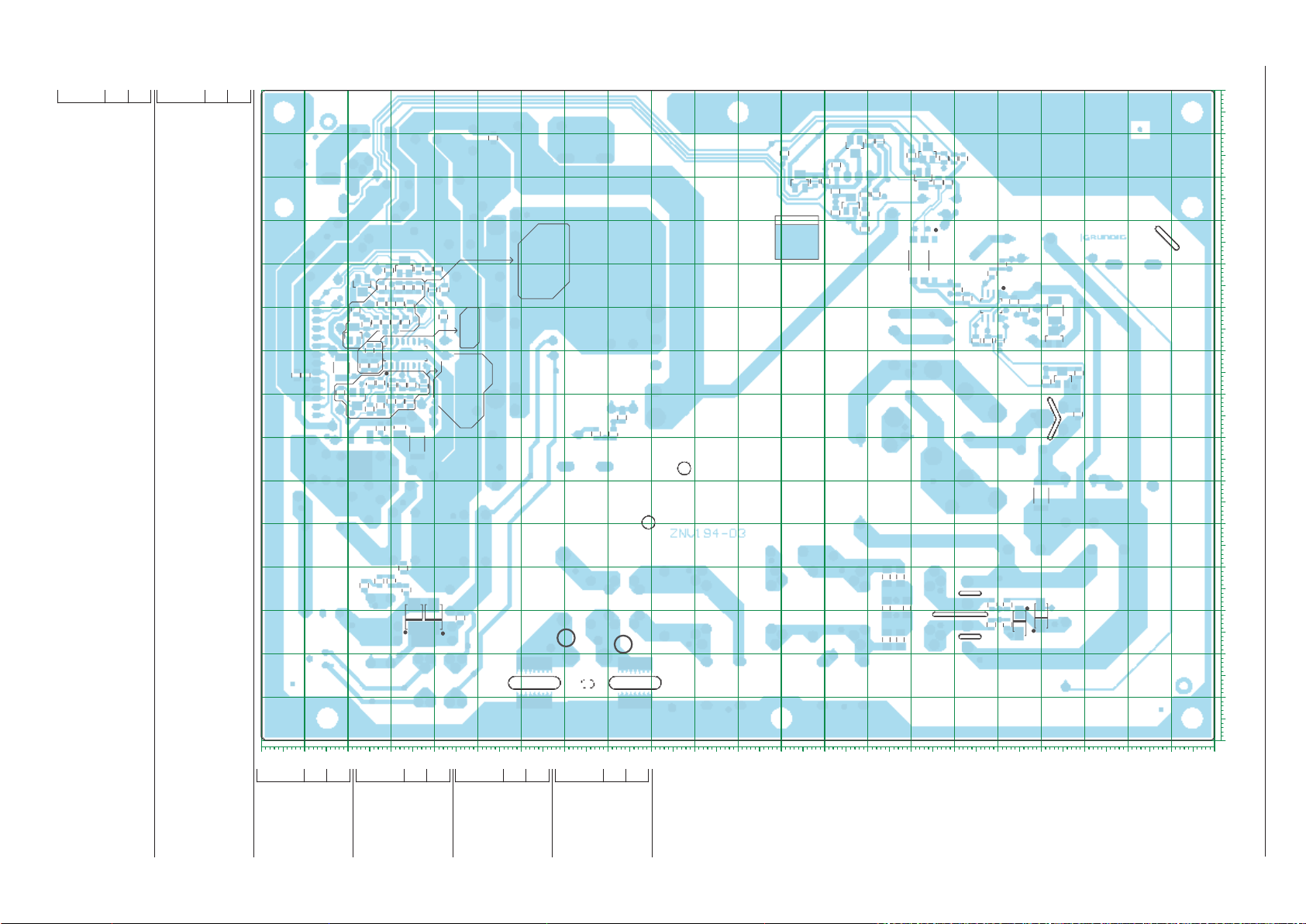
100
110
120
130
140
150
22
X
Netzteil / Power Supply ZNV194-03 Ansicht von der Lötseite / View of Solder Side
POS. X Y POS. X Y
R2040 B 212 84
R2041 B 32 75
R2042 B 60 134
R2043 B 81 122
R2500 T 190 25
R2501 B 178 98
R2502 B 190 82
R2503 B 181 104
R2504 B 202 86
R2505 B 196 96
R2506 B 202 80
R2507 B 186 105
R2508 B 184 105
R2509 B 193 83
R2510 B 195 77
R2511 B 186 100
R2512 B 187 97
R2513 B 195 83
R2514 B 193 72
R2515 B 184 109
R2516 B 192 101
R2517 B 189 97
R2518 B 188 101
R2519 T 195 25
R2520 B 186 78
R2521 B 188 72
R2522 B 183 82
2 - 19
R2523 B 192 105
R2524 B 193 90
R2525 B 184 69
R2526 T 180 67
R2527 B 191 97
R2528 B 188 78
R2529 B 190 78
R2530 B 182 109
R2531 B 179 109
S2000 T 208 88
S2001 T 204 126
S2002 T 150 35
S2003 T 145 19
S2500 T 207 19
SG2000 T 157 13
SG2001 T 134 13
T2000 T 39 74
T2001 B 67 130
T2500 B 199 94
T2501 B 197 67
T2503 B 197 105
TP1 B 137 77
TP2 B 139 73
TP3 B 50 37
TP4 B 70 87
TP5 B 159 121
TP6 B 65 98
TP7 B 141 70
TP8 B 54 19
TP9 B 65 60
TP10 B 165 63
TP11 B 100 133
TP12 B 42 75
TP13 B 72 72
TP14 B 46 98
TP15 B 48 96
TP16 B 39 86
TP17 B 32 82
TP18 B 63 35
TP19 B 63 27
TP20 B 61 103
TP21 B 48 99
TP22 B 52 95
TP23 B 50 90
TP24 B 55 96
TP25 B 35 95
TP26 B 86 8
TP27 B 85 120
TP28 B 31 101
TP29 B 66 118
TP30 B 74 32
TP31 B 74 29
TP32 B 81 124
TP33 B 47 111
TP34 B 53 106
TP35 B 50 28
TP36 B 47 24
TP37 B 47 109
TP38 B 86 39
TP39 B 86 26
TP40 B 37 27
TP41 B 50 30
TP42 B 38 31
TP43 B 61 106
TP44 B 76 126
TP45 B 69 118
TP46 B 76 130
TP47 B 90 132
TP48 B 102 41
TP49 B 51 116
TP50 B 60 122
TP51 B 62 132
TP52 B 71 131
TP53 B 121 22
TP54 B 67 139
TP55 B 88 124
TP56 B 121 39
TP57 B 112 7
TP58 B 199 141
TP59 B 102 138
TP60 B 148 39
TP61 B 158 18
TP62 B 134 18
TP63 B 176 52
TP64 B 205 116
TP65 B 92 140
TP66 B 210 80
TP67 B 202 102
TP68 B 205 103
TP69 B 188 36
TP70 B 194 31
TP71 B 188 20
FID3
HPG1
R2531
R2530
R2515
R2006
D2509
T2503
1
R2521
C2500
R2503
IC2500
R2506
D2505
R2525
C2502
D2503
D2508
D2502
BL
DIM
AD
R2040
C2009
12.5V
GND
GND
GND
12.5V
12.5V
12.5V
GND
0
FID2
R2504
R2514
T2501
C2510
C2501
C2511
LED+
LED-
C2516
R2501
R2513
R2510
C2007
R2508
R2523
C2520
R2516
R2518
R2511
C2513
R2512R2507
C2505
R2517C2517
R2527
R2505
T2500
C2521
R2524
C2514
C2515
R2522
R2509
C2518
C2506
R2502
R2520
R2528
R2529
C2512
L2502
HPL
L
C2003
C2004
C2024
HPN
N
POS. X Y POS. X Y POS. X Y POS. X Y
TP72 B 187 55
TP73 B 158 61
TP74 B 211 54
TP75 B 199 27
TP76 B 200 74
TP77 B 179 101
TP78 B 199 84
TP79 B 202 66
TP80 B 152 85
TP81 B 197 98
TP82 B 196 94
TP83 B 199 76
TP84 B 190 105
TP85 B 190 76
TP86 B 197 82
TP87 B 205 70
TP88 B 185 97
TP89 B 189 94
TP90 B 188 84
TP91 B 191 73
TP92 B 183 84
TP93 B 192 94
TP94 B 180 78
TP95 B 172 22
TP96 B 187 12
TP97 B 171 15
TP98 B 195 9
TR2000 T 102 87
HPG2
T: Bestückungsseite /
Component Side
B: Lötseite /
Solder Side
R2016
BARCODE
D2010
R2019
R2026
C2018
R2043
R2033
R2035R2034
C2019
R2029
T2001
IC2001
R2036
R2037
R2038
D2011
R2030
R2039
R2042
R2004
R2018
1
R2024
R2025
C2011
L2001
1
IC2000
R2014
C2012
C2013
R2017
R2015
R2027
R2022
R2003
D2004
R2013
D2001
R2012
R2041
R2000
R2028
D2008
D2007
R2023
IC2002
R2032
R2031
R2021
C2026
R2007
D2009
R2020
FID4
FID1
GRUNDIG Service Chassis G5
90
80
70
60
50
40
30
20
10
0
Y
0102030405060708090100110120130140150160170180190200210
Page 66
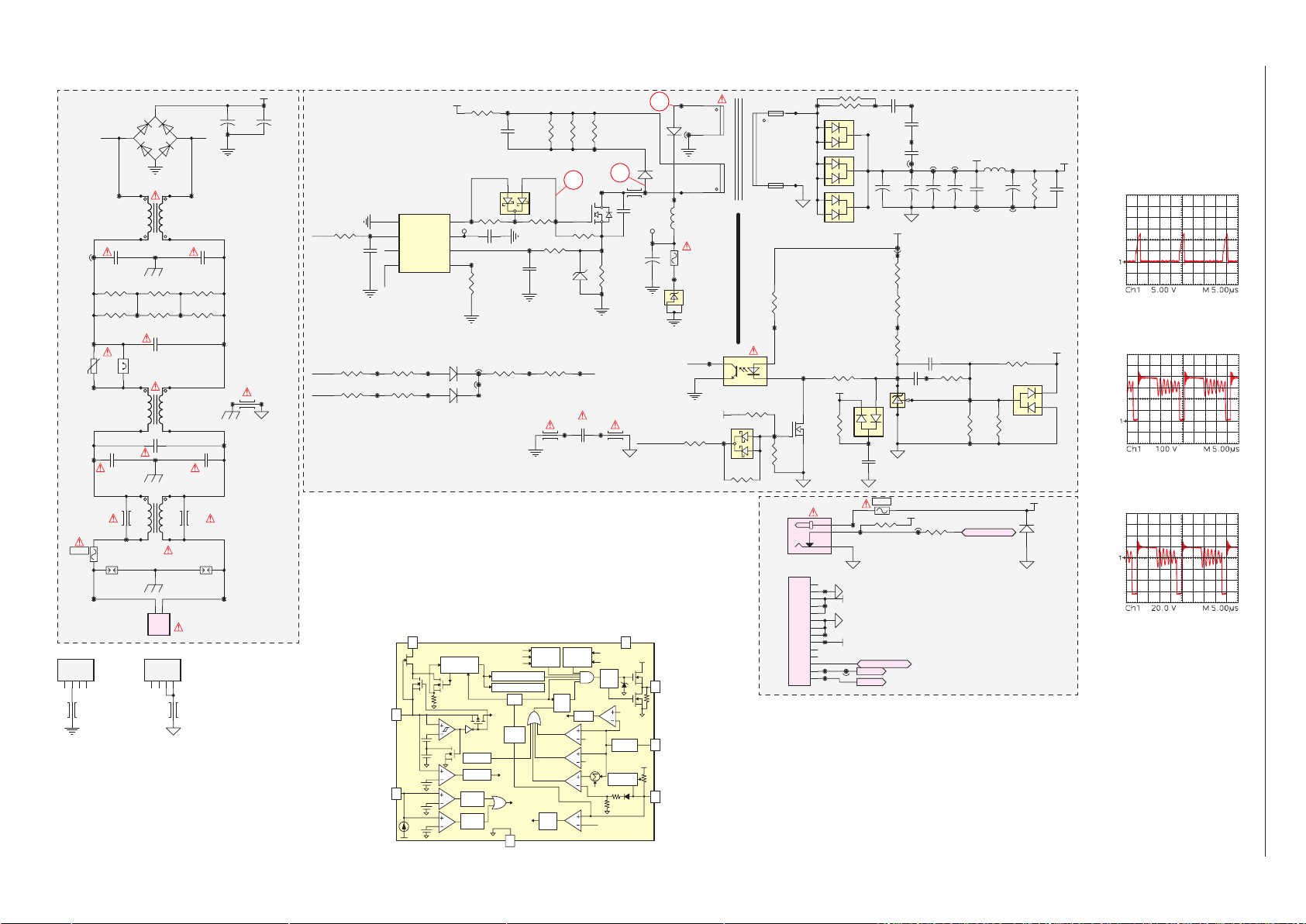
VBUS
GND_PRI
TR2000
1
2
3
VDD
SENSE
GND
HV
NC
Netzteil / Power Supply ZNV194-03
DB2000
GBL408
- +
TP26
C2017
220NF
305VAC
220NF
305VAC
TP57
P11P2
S2003
1
234
HV1HV2
~
3
4
4
TP19
L2002
L2006
L2007
4
3
3
C2015
220PF
400VAC
R2035
1M
1
4
4
L2005
L2008
L2009
3
3
21
2
L2018L2017
34
3
2
L2015
2 - 20
275V,
1.1A@140Vac
J2003
FUSE
FS2000
T2AL/250V
HS2001
HEATSINK
1
234
~
GND_PRI
2
1
1
TP18
1
2
2
C2014
220PF
400VAC
GND
R2033
R2034
1M
1M
R2036
R20371MR2038
1M
1M
TP30 TP31
TP38
R2011
0.7R
J2001
8A
1 2
1
1
TP48
342
2
2
C2021
C2023
TP56
220PF
400VAC
GND
1
4
TP60
L2019
L2014
S2002
SG2000 SG2001
TP61
HPL
L2013
GND
HS2000
HEATSINK
GND_PRI
TP39
TP53
C2022
220PF
400VAC
GND
TP62
HPN
GRUNDIG Service Chassis G5
100R
12
EL2000
8
EL2005
R2004
270R
TP29
TP45
32
1
T2001
R2029
2N7002LT1G
150K
S2001
KON DC PWR JACK
S2000
P1
P2
P3
P4
P5
P6
P7
P8
P9
P10
P11
P12
P13
P14
SMAW200-14
PWR
SNS
GND
TP5
1
3
1
3
1
3
R2018
R2007
1
2
3
4
5
6
7
8
9
10
11
12
13
14
R2001
TP63
D2000
D2002
D2012
12.5V_FL
47K
TP64
TP65
TP66
TP67
TP68
1
3
2
TP58
12.5V
12.5V
J2008
GND
FB
NC
SENSE
HV4RT
TP42
4
FAN6756
DD-OVP
1,05V
I
RT
0,7V
GATE
VDD
Line Sensing/
16,5V/9V
VBUS
R2002
RMF
0.22R
1W
R2012
8
TP15
VCC
10R
7
C2011
6
5
TP24
R2017
22K
GND_PRI
D2007
J2004
600V
D2008 J2005
600V
AX-CAP®
UVLO
Max. Duty
Debounce
t
D-OTP1
Counter
t
D-OTP2
Counter
TP4
1
3
TP16
100NF
50V
82K
R2024
TP33
TP40
VDDOVP
OTP
OLP for ML
Brownout Protection
V
Adjustment
Limit
OSC
Internal
BIAS
Green
Mode
OVP
1
C2002
3.3NF
630V
2
GND_PRI
TP22
GND_PRI
TP37
GND_PRI
OTP
OLP
D2001
BAT54C
30V
R2013
390R
R2015
330
C2013
1NF
50V
BZX55C5V1
R2025
75K
Latch
Protection
Soft-start
Comparator
Current Limit
Comparator
PWM
Comparator
OLP
Delay
EL2007
R2008
47K
EL2008
FQPF7N65C
TP17
D2005
TP49
Protection
Q
S
R
SSCP
OLP
Comparator
EL2010
R2009
47K
EL2009
1
T2000
R2041
47K
Re-start
TP34
C2020
470PF
t
D-SSCP
TP9
EL2012
R2010
47K
EL2011
1
TP23
TP28
GND_PRI
HV
TP50
Soft-start
V
Limit
Slope Comp.
TP12
EL2004
23
R2000
0.13R
L2004L2003
SSCP
OLP for MR
Soft
Driver
Blanking
Impedance
Modulator
3R
R
4,6V
2
L2016
C2016
47UF
3
VSCP-H/L
Circuit
C2010
100PF
1KV
GND_PRI
VCC
ADPT_DET
5V
TP3
+
+
C2000
C2001
68UF
68UF
450V
450V
TP8
IC2000
C2012
1NF
GND_PRI
1
2
TP20
3
FAN6756
HV
R2023
82K
TP35 TP36
R2028
82K
TP41
7
V
5
RT
L2012
GND_PRI
R2014
FB
100R
R2022
HV1
82K
R2027
HV2
82K
HPG1HPG2
3
D2003
MUR460
TP13
TP14
TP21
+
8GAT E
6
2FB
132
GND_PRI
1
TP6
D2006
UF4007F
2
J2000
GND_PRI
4
7
EL2013
L2001
10UH
R2003
PTC 032A 30V
TP25
D2004
BZX84C22-7-F
FB
TP43
GND_PRI
R2042
100R
E-40-0043C
IC2001
4
3
VO617A-4X007T
12.5V
3
TP54
R2030
D2011
BAT54C
30V
R2016
56K
1
2
TP51
1
2
0R
100RR2005
2
EL2001
30A
150V
2
EL2002
30A
150V
2
30A
EL2003
150V
1K
2
3
D2009
100V
TP55
R2039
ADPT_DET
TP59
ADPT_DETECT
DIM
BL
TP1
J2006
TP44
1
C2026
1UF
50V
FUSE
FS2001
C2003
2.2NF
50V
J2012
C2005
+
470UF
25V
12.5V_FL
2 3
T10A 250V
12.5V_FL
56K
TP27
R2020
470R
F
R2043
100R
F
TP32
R2021
470R
C2019
TP7
C2006
470UF
25V
C2018
100NF
1
J2011
TP2
C2024
2.2NF
50V
C2004
2.2NF
50V
TP10
+
IC2002
IC2003
J2007
TP46
R2006
100R
12.5V_FL
J2002
L2000
C2027
+
470UF
25V
J2010
TP47
R2031
8.2K
TP52
ADPT_DETECT
3.3UH
C2007
1UF
50V
C2025
+
470UF
25V
100NF
50V
R2026
22K
ADPT_DETECT
ADPT: OPEN DRAIN
No ADPT: LOW
MainBoard: 10k Pull up 3.3V
R2019
18K
3
R2032
10K
F
TP11
C2008
+
470UF
25V
J2009
D2010
100V
12.5V_FL
R2040
6.8K
12.5V
2
1
D2013
UF4007F
12.5V
C2009
1UF
50V
Page 67
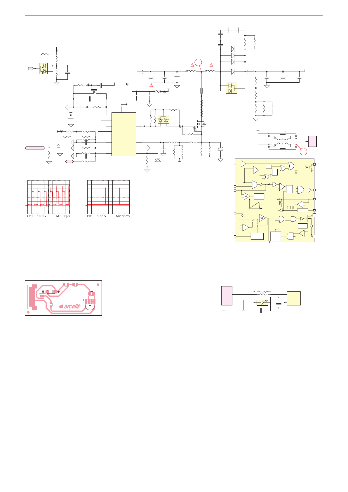
GRUNDIG Service Chassis G5
)
C2510
C2511
4
5
20µs Delay
ADIM
BDIM
T
ZGY192-01
10NFC2
6
5
Netzteil / Power Supply ZNV194-03
12.5V
2
1
VREF_1
T2503
1
R2523
150K
R2530
75K
R2531
56K
R2516
J2506
J2501
32
B_EN
VREF_1
R2511
100K
DIM
C2516
22NF
50V
100NF
TP85
0R
C2518
1UF
50V
C2513
TP88
R2517
R2518
C2520
R2522
C2521
R2527
R2510
10K
50V
R2512
100K
J2505
2
TP81
1NF
50V
100PF
50V
27K
18K
150K
100KR2524
10K
TP76
1
C2505
10NF
R2505
15K
C2512
22UF 10V
TP89
TP92
TP93
D2509
3
BL
BAT54C
ADPT_DETECT
R2515
1K
F
2N7002LT1G
T2500
2N7002LT1G
3
B_EN
OVP
TP82
14
12
13
15
16
VREF_1
5
6
7
CMP
REF
FAULT
ENA
OVP
ADIM
RT
BDIM
TP80
10
C2501
2.2NF
50V
C2500
2.2NF
50V
12.5V_FL
L2500
+
C2503
TP78
C2514
1UF
50V
2
4
3
8
PTC 0,32A 30V
47R
R2509
TP86
TP94
R2526
1.2R
470UF
25V
R2504
C2515
1UF
50V
47R
R2513
LED-
J2503
1
VCC
DRAIN9DRAIN
DRV
CS
GND
SENSE
FAN73402MXIC2500
1
TP90
D2507
15V
J2504
TP83
3
+
12.5V
2
C2506
100NF
50V
C2504
470UF
25V
R2506
0R
D2505
BAT54C
R2502
0R
J2502
TP72
R2528
30K
F
VREF_1
L2501 (a) L2501 (b)
LC-20-0013
C2502
1UF
50V
1
TP87
R2514
47K
R2520
1K
F
R2529
22K
F
4
43 1 6
TP74
L2503
TP79
J2507
J2508
J2509
J2510
J2511
J2512
T2501
FDD86102LZ
3 4
TP91
R2525
R2521
0.13R
0.04R
1W
F
2.2NF
50V
TP69
D2500
100V
D2501
100V
D2502
B2100-13-F
D2503
TP75
D2508
1
3
MBRD10200CT-13
200V
D2506
15V
OVP
CMP
GND
VCC
ENA
REF
2.2NF
50V
100V
B2100-13-F
100V
2
3V
Current
Sense
1.22V
5V, max. 3mA
TP70
R2500
R2519
100R
100R
ILED: 328mA (ADIM: Rtop: 200k, Rbot: 18k, RSENSE:1.2R)
ILED: 203mA (ADIM: Rtop: 200k, Rbot: 18k//27k, RSENSE: 1.2R
OVP: 85V (Rtop: 136k, Rbot: 10k//10k)
TP71
UVLO: (ON: 10.4V, OFF: 9.8V, RTOP: 75k, RBOT: 10k)
CS: Offset: 365mV, Sense: 135mV (Rsense:0.13R//0.04R)
J2500
R2501
68K
R2503
68K
R2507
10K
LED+
1µs
Delay
+
OCP
–
POR
640µs/200kHz
Auto-Restart
-
gm
+
PWM
Burst
Operation
3msat 200kHz
UVLO 9V
Voltage Ref.
& Int. Bias
OVP
R2508
10K
LED-
Hys. 1.0V
-
+
TP73
+
C2507
47UF
100V
TP95
1
L2505
2
TP97
TSD
CLK+LEB
at 200kHz
Debounce
C2517
1NF
50V
1
2
S
Q
R
1/4
BDIM
OLPi
OLP
40.96ms
Time
45µA
5k
L2504
L2507
-
+
OLPi
+
R
S
Dim off
C2508
47UF
100V
4
L2506
3
Switch Off
TP96
TP98
Q
L2502
OVP
+
100mV
ADIM*4
1.4~4V
0.3~3V
100mV
-
+
0.5V
4V
CMP:
16 Steps
Int. Soft-Start
-
+
Hys. 70mV
TP77
TP84
LED+
+
4
3
5
OLP
FAN73402
Dim off
Slope
PWM
Comp.
-
PWM
Current
Sense
PWM
End of Soft-Start
C2509
47UF
100V
3
2
1
+
+
-
0.2V
0.5V
S2500
Gate
Driver
P3
P2
P1
FAUL
DRV
CS
RTOscillator
Drain
SEN
IR-/LED-Platte / Board ZGY192-01
Ansicht von der Bestückungsseite / View of Component Side
SASI
1
CN1
ZGY192-01
D1
R2
R1
C2
C1
1
IR1
GND
GND
CN1
1
VCC
P1
2
IR_OUT
P2
LED_B
3
P3
GND
4
P4
150R
R1
R2
D1
150R
10UF
4
OUT
3
VS
2
GND/NC
1
C1
GND
IR1
TSOP36438
2 - 21
Page 68

GRUNDIG Service Chassis G5
Ersatzteilliste
Spare Parts List
NUR FÜR INTERNEN GEBRAUCH
FOR INTERNAL USE ONLY
1
TV
Ersatzteilliste
Spare Parts List
NUR FÜR INTERNEN GEBRAUCH
FOR INTERNAL USE ONLY
1
TV
3 - 1
11 / 2016 32 VLE 5620 BN
BESTELL-NR. / ORDER NO.: PSN000 (PSN)
Pos. Fig. Material-Nr. Ref. d Bezeichnung © Description
Part No.
PSN000 * 32 VLE 5620 BN 32 VLE 5620 BN
PRODUKTCODE PSN PRODUCT CODE PSN
001.000 759551854300 GEH.-VORDERTEIL SCHWARZ FRONT CABINET BLACK
001.100 759551729100 LED-LINSE LED-LENSE
002.000 759551847100 RUECKWAND SCHWARZ BACK COVER BLACK
003.000 759551862600 GEH.-MITTELTEIL SCHWARZ CABINET MIDDLEPART BLACK
005.100 759551871700 STANDFUSS LINKS SCHWARZ STAND FOOT LEFT BLACK
005.200 759551871800 STANDFUSS RECHTS SCHWARZ STAND FOOT RIGHT BLACK
005.300 759551696100 STANDFUSS SCHRAUBE SCHWARZ M4X10 STANDFOOTSCREW BLACK M4X10
005.400 759551703500 STANDFUSS SCHRAUBE SCHWARZ M4X12 STANDFOOT SCREW BLACK M4X12
006.100 759551852200 STANDFUSSHALTER RIGHT SCHWARZ STANDFOOTHOLDER RIGHT BLACK
006.200 759551852300 STANDFUSSHALTER LINKS SCHWARZ STANDFOOTHOLDER LEFT BLACK
015.000 759551841700 LAUTSPRECHER 8R 10/15W 192x32MM SPEAKER 8R 10/15W 192x32MM
019.000 759551626200 KABEL LVDS 51P 300MM CABLE LVDS 51P 300MM
020.000 S 057D32B13P * LCD BMS 056D32A96P LEDB CN-G7/DI LCD BMS 056D32A96P LEDB CN-G7/DI
020.001 S 052D32LP2P * LCD LC320EUJ-FFE2 FHD 50HZ LCD LC320EUJ-FFE2 FHD 50HZ
020.002 S 759551882300 LED BAR 32 (ZPZ) LED BAR 32 (ZPZ)
020.100 S 759551839300 T-CON MODUL (XMG) T-CON BOARD (XMG)
020.101 759551847700 FLACHBANDKABEL 50P 0,5MM 68MM CABLE FFC 50P 0.5MM 68MM
022.000 S 275990325500 X NETZTEIL (ZQA) POWER SUPPLY (ZQA)
022.100 S 759551863700 NETZKABEL POWER CORD
022.200 759551863800 KABEL NETZEIL-CHASSIS 33CM CABLE POWER-CHASSIS 33CM
025.000 S 275991261000 X CHASSISMODUL G5 (PSN) CHASSIS BOARD G5 (PSN)
027.000 759551767800 FERNBEDIENUNG TP6 VER. 3 REMOTE CONTROL TP6 VER. 3
028.000 720117145300 FERNBEDIENUNG TP EASY SCHWARZ REMOTE CONTROL TP EASY BLACK
031.000 759551793400 IR/LED MODUL (ZGP) IR/LED BOARD (ZGP)
031.100 759551786600 IR-EMPFAENGER TSOP36438TT IR-RECEIVER TSOP36438TT
031.200 759551549100 LED-SMD 1206 BLAU 250MCD 3.3V LED-SMD 1206 BLUE 250MCD 3.3V
031.300 759551851700 FLACHBANDKABEL 4P 1MM 450MM CABLE FFC 4PIN 1MM 450MM
090.000 759551847400 KARTON 32 CARTON 32
091.000 759551847500 POLSTER 4-TEILIG CUSHION 4 PARTS
* KEIN ERSATZTEIL * NO SPARE PART
X = SIEHE GESONDERTE E-LISTE X = SEE SEPARATE PARTS LIST
DIE BEDIENUNGSANLEITUNG IST THE INSTRUCTION MANUAL CAN BE
UEBER FOLGENDER ADRESSE ABRUFBAR: DOWNLOAD FROM ADRESS:
WWW.GRUNDIG.DE/SERVICE/DOWNLOADS WWW.GRUNDIG.DE/SERVICE/DOWNLOADS
Hinweis:
Sollte in dieser Ersatzteilliste Ihr „Product Code“
oder Ihre Display-Variante nicht aufgeführt sein,
finden Sie eine aktualisierte Version auf dem
Service-Portal „http://service.grundig.de“.
Note:
If your “Product Code” or display variant is
not mentioned in the spare parts list, please
look for a current version at the service portal
“http://service.grundig.de”.
12 / 2016 43 VLE 5620 BN
BESTELL-NR. / ORDER NO.: PSP000 (PSP)
Pos. Fig. Material-Nr. Ref. d Bezeichnung © Description
Part No.
PSP000 * 43 VLE 5620 BN 43 VLE 5620 BN
PRODUKTCODE PSP PRODUCT CODE PSP
001.000 759551851900 GEH.-VORDERTEIL SCHWARZ FRONT CABINET BLACK
001.100 759551729100 LED-LINSE LED-LENSE
002.000 759551852000 RUECKWAND SCHWARZ BACK COVER BLACK
003.000 759551860700 GEH.-MITTELTEIL SCHWARZ CABINET MIDDLEPART BLACK
005.100 759551871700 STANDFUSS LINKS SCHWARZ STAND FOOT LEFT BLACK
005.200 759551871800 STANDFUSS RECHTS SCHWARZ STAND FOOT RIGHT BLACK
005.300 759551696100 STANDFUSS SCHRAUBE SCHWARZ M4X10 STANDFOOTSCREW BLACK M4X10
005.400 759551703500 STANDFUSS SCHRAUBE SCHWARZ M4X12 STANDFOOT SCREW BLACK M4X12
006.100 759551852200 STANDFUSSHALTER RIGHT SCHWARZ STANDFOOTHOLDER RIGHT BLACK
006.200 759551852300 STANDFUSSHALTER LINKS SCHWARZ STANDFOOTHOLDER LEFT BLACK
015.000 759551841700 LAUTSPRECHER 8R 10/15W 192x32MM SPEAKER 8R 10/15W 192x32MM
019.000 759551626200 KABEL LVDS 51P 300MM CABLE LVDS 51P 300MM
020.000 S 057D43A25P * LCD BMS 056D43A09P CN-G7/DI-DK LCD BMS 056D43A09P CN-G7/DI-DK
020.001 S 052D43LG1P * LCD LC430DUY-SHA1 FHD 50HZ LCD LC430DUY-SHA1 FHD 50HZ
020.002 S 759551880000 LED BAR LINKS 43 (ZLD) LED BAR LEFT 43 (ZLD)
020.003 S 759551880100 LED BAR RECHTS 43 (ZLE) LED BAR RIGHT 43 (ZLE)
020.100 S 759551844900 T-CON MODUL 43 PL 6871L-3806B T-CON BOARD 43 PL 6871L-3806B
020.101 759551847600 FLACHBANDKABEL 50P 0,5MM 81MM CAB.FFC 50PIN 0.5MM L=81MM
021.000 S 759551852700 LED-CONVERTER (ZPR) LED CONVERTER (ZPR)
022.000 S 275990327100 NETZTEIL (ZQR) POWER SUPPLY (ZQR)
022.100 S 759551841600 NETZKABEL POWER CORD
022.200 759551861600 KABEL NETZTEIL-CHASSIS 470MM CABLE POWER-CHASSIS 470MM
025.000 S 275991261100 X CHASSISMODUL G5 (PSP) *1 CHASSIS BOARD G5 (PSP) *1
025.000 S 275991261900 X CHASSISMODUL G5 (N49) *2 CHASSIS BOARD G5 (N49) *2
027.000 759551767800 FERNBEDIENUNG TP6 VER. 3 REMOTE CONTROL TP6 VER. 3
028.000 720117145300 FERNBEDIENUNG TP EASY SCHWARZ REMOTE CONTROL TP EASY BLACK
031.000 759551793400 IR/LED MODUL (ZGP) IR/LED BOARD (ZGP)
031.100 759551786600 IR-EMPFAENGER TSOP36438TT IR-RECEIVER TSOP36438TT
031.200 759551549100 LED-SMD 1206 BLAU 250MCD 3.3V LED-SMD 1206 BLUE 250MCD 3.3V
031.300 759551851700 FLACHBANDKABEL 4P 1MM 450MM CABLE FFC 4PIN 1MM 450MM
090.000 759551841800 KARTON 43 CARTON 43
091.000 759551841900 POLSTER 4-TEILIG CUSHION 4 PARTS
* KEIN ERSATZTEIL * NO SPARE PART
X = SIEHE GESONDERTE E-LISTE X = SEE SEPARATE PARTS LIST
DIE BEDIENUNGSANLEITUNG IST THE INSTRUCTION MANUAL CAN BE
UEBER FOLGENDER ADRESSE ABRUFBAR: DOWNLOAD FROM ADRESS:
WWW.GRUNDIG.DE/SERVICE/DOWNLOADS WWW.GRUNDIG.DE/SERVICE/DOWNLOADS
Hinweis:
Sollte in dieser Ersatzteilliste Ihr „Product Code“
oder Ihre Display-Variante nicht aufgeführt sein,
finden Sie eine aktualisierte Version auf dem
Service-Portal „http://service.grundig.de“.
Note:
If your “Product Code” or display variant is
not mentioned in the spare parts list, please
look for a current version at the service portal
“http://service.grundig.de”.
Es gelten die Vorschriften und Sicherheitshinweise gemäß dem Service
Manual „Sicherheit“, Mat.-Nummer 720108000001, sowie zusätzlich die
eventuell abweichenden, landesspezifischen Vorschriften!
ÄNDERUNGEN VORBEHALTEN / SUBJECT TO ALTERATION
The regulations and safety instructions shall be valid as provided by
S
the „Safety“ Service Manual, part number 720108000001, as well as
( ! )
the respective national deviations.
Es gelten die Vorschriften und Sicherheitshinweise gemäß dem Service
Manual „Sicherheit“, Mat.-Nummer 720108000001, sowie zusätzlich die
eventuell abweichenden, landesspezifischen Vorschriften!
ÄNDERUNGEN VORBEHALTEN / SUBJECT TO ALTERATION
The regulations and safety instructions shall be valid as provided by
S
the „Safety“ Service Manual, part number 720108000001, as well as
( ! )
the respective national deviations.
Page 69

3 - 2
GRUNDIG Service Chassis G5
Ersatzteilliste
Spare Parts List
NUR FÜR INTERNEN GEBRAUCH
FOR INTERNAL USE ONLY
1
TV
12 / 2016 49 VLE 5620 BN
BESTELL-NR. / ORDER NO.: PSQ000 (PSQ)
Pos. Fig. Material-Nr. Ref. d Bezeichnung © Description
Part No.
PSQ000 * 49 VLE 5620 BN 49 VLE 5620 BN
PRODUKTCODE PSQ PRODUCT CODE PSQ
001.000 759551851500 GEH.-VORDERTEIL SCHWARZ FRONT CABINET BLACK
001.100 759551729100 LED-LINSE LED-LENSE
002.000 759551887300 RUECKWAND SCHWARZ BACK COVER BLACK
003.000 759551865100 GEH.-MITTELTEIL SCHWARZ CABINET MIDDLEPART BLACK
005.100 759551871700 STANDFUSS LINKS SCHWARZ STAND FOOT LEFT BLACK
005.200 759551871800 STANDFUSS RECHTS SCHWARZ STAND FOOT RIGHT BLACK
005.300 759551696100 STANDFUSS SCHRAUBE SCHWARZ M4X10 STANDFOOTSCREW BLACK M4X10
005.400 759551703500 STANDFUSS SCHRAUBE SCHWARZ M4X12 STANDFOOT SCREW BLACK M4X12
006.100 759551852200 STANDFUSSHALTER RIGHT SCHWARZ STANDFOOTHOLDER RIGHT BLACK
006.200 759551852300 STANDFUSSHALTER LINKS SCHWARZ STANDFOOTHOLDER LEFT BLACK
015.000 759551841700 LAUTSPRECHER 8R 10/15W 192x32MM SPEAKER 8R 10/15W 192x32MM
019.000 759551600400 KABEL DISPLAY-LVDS 500MM CABLE DISPLAY-LVDS 500MM
020.000 S 057D49A43P * LCD BMS 056D49A29P LEDB CN-G7 LCD BMS 056D49A29P LEDB CN-G7
020.001 S 052D49LG3P * LCD LC490DUY-SHA1 FHD 2D POL LCD LC490DUY-SHA1 FHD 2D POL
020.002 S 759551880400 LED BAR LINKS 49 (ZLF) LED BAR LEFT 49 (ZLF)
020.003 S 759551880500 LED BAR RECHTS 49 (ZLG) LED BAR RIGHT 49 (ZLG)
020.100 S 759551865300 T-CON MODUL (XMJ) T-CON BOARD (XMJ)
020.101 759551852600 FLACHBANDKABEL 50P P=0,5MM 88MM CABLE FFC 50P P=0,5MM 88MM
021.000 S 759551852500 LED-CONVERTER (ZPS) LED CONVERTER (ZPS)
022.000 S 275990327100 NETZTEIL (ZQR) POWER SUPPLY (ZQR)
022.100 S 759551841600 NETZKABEL POWER CORD
022.200 759551861500 KABEL NETZTEIL-CHASSIS 650MM CABLE POWER-CHASSIS 650MM
025.000 S 275991261200 X CHASSISMODUL G5 (PSQ) *1 CHASSIS BOARD G5 (PSQ) *1
025.000 S 275991262000 X CHASSISMODUL G5 (N4A) *2 CHASSIS BOARD G5 (N4A) *2
027.000 759551767800 FERNBEDIENUNG TP6 VER. 3 REMOTE CONTROL TP6 VER. 3
028.000 720117145300 FERNBEDIENUNG TP EASY SCHWARZ REMOTE CONTROL TP EASY BLACK
031.000 759551793400 IR/LED MODUL (ZGP) IR/LED BOARD (ZGP)
031.100 759551786600 IR-EMPFAENGER TSOP36438TT IR-RECEIVER TSOP36438TT
031.200 759551549100 LED-SMD 1206 BLAU 250MCD 3.3V LED-SMD 1206 BLUE 250MCD 3.3V
031.300 759551851700 FLACHBANDKABEL 4P 1MM 450MM CABLE FFC 4PIN 1MM 450MM
090.000 759551846300 KARTON 49 CARTON 49
091.000 759551846400 POLSTER 4-TEILIG CUSHION 4-PARTS
* KEIN ERSATZTEIL * NO SPARE PART
X = SIEHE GESONDERTE E-LISTE X = SEE SEPARATE PARTS LIST
DIE BEDIENUNGSANLEITUNG IST THE INSTRUCTION MANUAL CAN BE
UEBER FOLGENDER ADRESSE ABRUFBAR: DOWNLOAD FROM ADRESS:
WWW.GRUNDIG.DE/SERVICE/DOWNLOADS WWW.GRUNDIG.DE/SERVICE/DOWNLOADS
Hinweis:
Sollte in dieser Ersatzteilliste Ihr „Product Code“
oder Ihre Display-Variante nicht aufgeführt sein,
finden Sie eine aktualisierte Version auf dem
Service-Portal „http://service.grundig.de“.
Note:
If your “Product Code” or display variant is
not mentioned in the spare parts list, please
look for a current version at the service portal
“http://service.grundig.de”.
Es gelten die Vorschriften und Sicherheitshinweise gemäß dem Service
Manual „Sicherheit“, Mat.-Nummer 720108000001, sowie zusätzlich die
eventuell abweichenden, landesspezifischen Vorschriften!
ÄNDERUNGEN VORBEHALTEN / SUBJECT TO ALTERATION
The regulations and safety instructions shall be valid as provided by
S
the „Safety“ Service Manual, part number 720108000001, as well as
( ! )
the respective national deviations.
Page 70
Ersatzteilliste / Spare Parts List
TV
12 / 2016 CHASSISMODUL / CHASSIS BOARD G5
Chassis SUGRUNDIG Service
3 - 3
NUR FÜR INTERNEN GEBRAUCH / FOR INTERNAL USE ONLY
Chassis G5GRUNDIG Service
3 - 3
275991261000
275991261100
275991261200
275991261900
275991262000
Pos.
D400
Part Number
759551832600
Description
DIO-SMD ESD PRTR5V0U2X SOT143B
PCB
Code
D700
D701
D702
D703
759551262400
759551262400
DIODE PMEG4010EH SOD123
DIODE PMEG4010EH SOD123
759551262400
759551262400
DIODE PMEG4010EH SOD123
DIODE PMEG4010EH SOD123
D704
D902
D903
IC100
759551860800
759551497600
DIODE-SMD ESD NUP1301
DIODE STKY-SMD PMEG2020EH 2A 20V
759551497600
759551860900
DIODE STKY-SMD PMEG2020EH 2A 20V
IC-SMD MSD93F4TW2-4-0042 BGA
IC102
IC200
759551863600
759551861000
IC-SMD MSD93F4TW2-4-0063 BGA
IC-SMD AT30TS74-MA8M-T UDFN
759551867600
759551561000
IC-SMD LM75BTP HWSON8
IC-SMD APX812-29UG-7
IC400
IC401
IC402
IC500
759551861100
759551729600
IC-SMD TPS2065CDBVR-2 SOT23-5
IC-SMD TPS2530DBVR SOT23-5
759551861100
759551729600
IC-SMD TPS2065CDBVR-2 SOT23-5
IC-SMD TPS2530DBVR SOT23-5
IC501
IC600
IC700
IC701
759551498600
759551771600
IC-SMD NC7SZ08P5X SOT353
IC-SMD DRV632PWR TSSOP
759551849700
759551849800
IC-SMD Si2151-A10-GMR QFN
IC-SMD XC8101AA01GR-G USP-4
IC702
IC703
IC800
IC801
759551822500
759551729500
IC-SMD AV2018-S85QFG QFN16
IC-SMD LNBH29EQTR QFN16
759551771800
759551605900
IC-SMD TAS5739MDPHPR QFP
IC-SMD AP432SRG-7 SOT23R
IC900
IC901
IC902
IC903
759551831400
759551781600
IC-SMD XC6222B181ER-G USP-6C
IC-SMD TPS562200DDCR SOT23-6
759551781600
759551861200
IC-SMD TPS562200DDCR SOT23-6
IC-SMD TPS56528DDAR SO
IC904
IC905
IC906
759551781500
759551729600
IC-SMD TPS542941RSAR
IC-SMD TPS2530DBVR SOT23-5
759551771500
759551729600
IC-SMD XC8107AC10MR-G SOT23-5
IC-SMD TPS2530DBVR SOT23-5
IC1000
IC1101
IC1104
IC1105
759551831600
759551861100
IC-SMD K4B4G1646E-BCMAT00 FBGA
IC-SMD TPS2065CDBVR-2 SOT23-5
759551498600
759551498600
IC-SMD NC7SZ08P5X SOT353
IC-SMD NC7SZ08P5X SOT353
IC1106
IC1300
IC1400
IC1402
759551498600
759551861300
IC-SMD NC7SZ08P5X SOT353
IC-SMD TH58NVG2S3HTA00 TSOPI
759551872000
759551872100
IC-SMD MST7458EB EPLQFP
IC-SMD W25Q80DVSSIG SOIC8
L400
L401
L402
L700
759551606800
759551606800
BOB-SMD 3.3UH %20 1.2A 0.09R 1008
BOB-SMD 3.3UH %20 1.2A 0.09R 1008
759551606800
759551730300
BOB-SMD 3.3UH %20 1.2A 0.09R 1008
BOB-SMD 270NH 0.1A 0402
L701
L702
L703
L704
759551730300
759551730300
BOB-SMD 270NH 0.1A 0402
BOB-SMD 270NH 0.1A 0402
759551832800
759551730400
BOB-SMD 270NH %5 420MA 0.52R 0402
BOB-SMD 180NH 0.1A 0402
L705
L708
L710
L711
759551730300
759551606800
BOB-SMD 270NH 0.1A 0402
BOB-SMD 3.3UH %20 1.2A 0.09R 1008
759551832700
759551730100
BOB-SMD 7.5 NH %5 0.3A 0.25R 0402
BOB-SMD 6.8UH 2.5A 0.052R 4.9MM2
L713
L800
L801
759551699700
759551562500
BOB-SMD 27NH J 0.59A 0603
SMD SPULE 22UH 1.9A
759551867800
759551562500
COIL-SMD 33UH M 1.4A 6*6*4.5
SMD SPULE 22UH 1.9A
L802
L803
759551867800
759551562500
COIL-SMD 33UH M 1.4A 6*6*4.5
SMD SPULE 22UH 1.9A
759551867800
759551562500
COIL-SMD 33UH M 1.4A 6*6*4.5
SMD SPULE 22UH 1.9A
L904
L905
759551867800
759551561300
COIL-SMD 33UH M 1.4A 6*6*4.5
SMD SPULE 3.3UH 2A
759551876100
759551561300
COIL-SMD 3.3UH M 2A 4*4*1.8
SMD SPULE 3.3UH 2A
L908
L909
759551876100
759551861400
COIL-SMD 3.3UH M 2A 4*4*1.8
BOB-SMD 1.5UH 5.3A 8*8*3
759551561300
759551876100
SMD SPULE 3.3UH 2A
COIL-SMD 3.3UH M 2A 4*4*1.8
L911
L1100
S101
S402
759551781300
759551606800
BOB-SMD 6.3UH 3.6A 0.036R 6*6*4.5
BOB-SMD 3.3UH %20 1.2A 0.09R 1008
759551850200
759551833700
CON-SMD FFC LVDS 51P 0.5MM H.LOCK
CON-SMD 6PIN 1.5MM FEMALE HOR.
S403
S404
S405
S500
759551832500
759551832500
CON-SMD USB HOR 13.8MM
CON-SMD USB HOR 13.8MM
759551859000
759551850500
CON RJ45 RJ127-F08M2BE-A
CON CI H=10.25MM BOX 1.2MM
S600
S601
S602
S700
759551850600
759551850300
CON PHONEJACK EJ328-3 3.5MM 1.2MM
CON SCART 1.2MM CN SASI 2.5MM
759551850400
759551850800
SOCKET SPDIF 1.2MM
SOCKET TUN.ANT. H=10MM 1.2MM
S701
S800
S801
S900
759551850900
759551833300
SOCKET F-TYPE 1.2MM
CON-SMD 4PIN 1.5MM FEMALE HOR.
759551770400
759551850700
KOPFHOERERBU. STEREO 3.5MM H=7MM
CON-SMD 14PIN 2MM 20037WR
S901
S906
S1100
S1101
759551833800
759551850100
KON-SMD 6PIN 1MM KLTL YTK
CONN.HDMI HORIZONTAL 1.2MM
759551850100
759551850100
CONN.HDMI HORIZONTAL 1.2MM
CONN.HDMI HORIZONTAL 1.2MM
S1200
S1201
S1202
S1203
759551853600
759551853600
TASTSCHALTER
TASTSCHALTER
759551834100
759551853600
CON-SMD 4PIN 1MM H=6MM YTK KLTL
TASTSCHALTER
S1204
T901
T902
T1104
759551853600
759551388500
TASTSCHALTER
TRANS-CHIP PMV65XP P-CH
759551098300
759551833900
TRANS BC847BDW1T1
TRN-CHIP 2N7002P SOT23
X200
X700
X701
X1400
759551851100
759551851100
CRS-SMD 24MHZ 8.5PF-30PPM 2.0x1.6
CRS-SMD 24MHZ 8.5PF-30PPM 2.0x1.6
759551851200
759551851100
CRS-SMD 27MHZ 6.0PF-30PPM 2.0x1.6
CRS-SMD 24MHZ 8.5PF-30PPM 2.0x1.6
Chassis G5
PSN
PSP
PSQ
X
X
X
X
XXX
X
XXX
X
XXXXX
X
XX
X
X
X
XX
XXX
X
X
X
X
XXX
X
XX
X
X
X
X
XXX
X
XXX
X
X
X
X
X
XXX
X
XXX
X
X
X
X
XX
XXX
X
X
X
X
XXX
X
XX
X
X
X
X
XXX
X
XXX
X
XXXXX
X
X
X
X
X
XXX
X
XXX
X
X
X
X
X
XXX
X
XXX
X
X
X
X
X
XXX
X
XXX
X
X
X
X
XXX
X
XX
XXXX
XX
XXX
X
X
X
XXX
X
XX
X
X
X
XXX
X
XX
X
X
X
XXX
X
XX
X
X
X
X
XXX
X
XXX
X
X
X
X
X
XXX
X
XXX
X
X
X
X
XX
XXX
X
X
X
X
X
XXX
X
XXX
X
X
X
X
X
XXX
X
XXX
X
X
X
X
XXX
X
XX
N49
N4A
XXX
X
XXX
X
XXX
X
XX
XX
XXX
X
XXX
X
XX
XXX
X
XXX
X
XXX
X
XXX
X
XX
XXX
X
XXX
X
XX
XXX
X
XXX
X
XXX
X
XXX
X
XXX
X
XXX
X
XXX
X
XXX
X
XXX
X
XXX
X
XX
XX
XX
XX
XXX
X
XX
XXX
X
XX
XXX
X
XX
XXX
X
XXX
X
XXX
X
XXX
X
XX
XXX
X
XXX
X
XXX
X
XXX
X
XXX
X
XXX
X
XX
 Loading...