

Page 1

GRUNDFOS INSTRUCTIONS
LCSE, VLSE
Grundfos E-pumps with MLE frequency-controlled
permanent-magnet motors
Installation and operating instructions
Page 2

English (US)
English (US) Installation and operating instructions
Original installation and operating instructions
These installation and operating instructions describe Grundfos
LCSE, VLSE.
Sections 1-4 give the information necessary to be able to unpack,
install and start up the product in a safe way.
Sections 5-11 give important information about the product, as
well as information on service, fault finding and disposal of the
product.
CONTENTS
Page
1. Limited warranty
2. General information
2.1 Hazard statements
2.2 Notes
2.3 Abbreviations and definitions
3. Receiving the product
3.1 Transporting the product
3.2 Inspecting the product
4. Installing the product
4.1 Mechanical installation
4.2 Electrical installation
4.3 Installing a communication interface module
4.4 Changing the position of the control panel
5. Product introduction
5.1 Product description
5.2 Identification
5.3 Bus signal
5.4 Grundfos Eye
5.5 Signal relays
6. User interfaces
6.1 Advanced control panel
6.2 Grundfos GO
6.3 R100 remote control
7. Description of functions
7.1 "Setpoint"
7.2 "Operating mode"
7.3 "Set manual speed"
7.4 "Control mode"
7.5 "Analog inputs"
7.6 "Pt100/1000 inputs"
7.7 "Digital inputs"
7.8 "Digital inputs/outputs"
7.9 "Signal relays" 1 and 2 ("Relay outputs")
7.10 "Analog output"
7.11 "Controller" ("Controller settings")
7.12 "Operating range"
7.13 "External setpoint function"
7.14 "Predefined setpoints"
7.15 "Limit-exceeded function"
7.16 "LiqTec" ("LiqTec function")
7.17 "Stop function" ("Low-flow stop function")
7.18 "Pipe filling function"
7.19 "Pulse flowmeter" ("Pulse flowmeter setup")
7.20 "Ramps"
7.21 "Standstill heating"
7.22 "Motor bearing monitoring"
7.23 "Service"
7.24 "Number" ("Pump number")
7.25 "Radio communication" ("Enable/disable radio comm.")
7.26 "Language"
7.27 "Date and time" ("Set date and time")
7.28 "Unit configuration" ("Units")
14
15
16
16
17
17
18
19
20
20
25
29
31
31
31
31
31
36
37
37
38
39
40
41
42
42
45
46
47
47
49
49
50
50
50
51
51
51
51
52
52
7.29 "Buttons on product" ("Enable/disable settings")
7.30 "Delete history"
7.31 "Define Home display"
7.32 "Display settings"
7.33 "Store settings" ("Store actual settings")
7.34 "Recall settings" ("Recall stored settings")
7.35 "Pump name"
7.36 "Connection code"
7.37 "Run start-up guide"
7.38 "Alarm log"
7.39 "Warning log"
7.40 "Assist"
3
3
3
4
4
5
5
5
5
5
6
7.41 "Assisted pump setup"
7.42 "Setup, analog input"
7.43 "Setting of date and time"
7.44 "Multi-pump setup" ("Setup of multi-pump system")
7.45 "Description of control mode"
7.46 "Assisted fault advice"
8. Description of settings
8.1 Priority of settings
8.2 Factory settings
9. Servicing the product
9.1 Motor
9.2 Pump
9.3 Cleaning the product
10. Technical data
10.1 Operating conditions
10.2 Megging
10.3 Technical data, single-phase motors
10.4 Technical data, three-phase motors
10.5 Inputs/outputs
10.6 Other technical data
11. Disposing of the product
Prior to installation, read this document. Installation
and operation must comply with local regulations and
accepted codes of good practice.
52
52
53
53
53
53
53
54
54
54
55
55
55
55
55
56
58
58
59
59
60
61
61
61
61
62
62
62
62
63
63
64
65
2
Page 3

1. Limited warranty
New equipment manufactured by seller or service supplied by
seller is warranted to be free from defects and workmanship
under normal use and service for a minimum of twenty-four (24)
months from date of installation, thirty (30) months from date of
shipment, unless otherwise stated in product warranty guide
(available upon request). In the case of spare or replacement
parts manufactured by seller, the warranty period shall be for a
period of twelve months from shipment.
Sellers obligation under this warranty is limited to repairing or
replacing, at its option, any part found to its satisfaction to be so
defective, provided that such part is, upon request, returned to
seller’s factory from which it was shipped, transportation prepaid.
Parts replaced under warranty shall be warranted for twelve
months from the date of the repair, not to exceed the original
warranty period. This warranty does not cover parts damaged by
decomposition from chemical action or wear caused by abrasive
materials, nor does it cover damage resulting from misuse,
accident, neglect, or from improper operation, maintenance,
installation, modification, or adjustment. This warranty does not
cover parts repaired outside seller’s factory without prior written
approval. Seller makes no warranty as to starting equipment,
electrical apparatus or other material not of its manufacture. If
purchaser or others repair, replace, or adjust equipment or parts
without sellers prior written approval, seller is relieved of any
further obligation to purchaser under this paragraph with respect
to such equipment or parts, unless such repair, replacement, or
adjustment was made after seller failed to satisfy within a
reasonable amount of time seller’s obligations under this
paragraph. Sellers liability for breach of these warranties (or for
breach of any other warranties found by a court of competent
jurisdiction to have been given by seller) shall be limited to: (A)
accepting return of such equipment EXW plant of manufacture
and (B) refunding any amount paid thereon by purchaser (less
depreciation at the rate of 15 % per year if purchaser has used
equipment for more than thirty [30] days), and cancelling any
balance still owing on the equipment or (C) in the case of service,
at the sellers option, redoing the service, or refunding the
purchase order amount of the service or portion thereof upon
which such liability is based. These warranties are expressly in
lieu of any other warranties, express or implied, and seller
specifically disclaims any implied warranty of merchantability or
fitness for a particular purpose, and in lieu of any other obligation
or liability on the part of the seller whether a claim is based upon
negligence, breach of warranty, or any other theory or cause of
action. In no event shall seller be liable for any consequential,
incidental, indirect, special or punitive damages of any kind. For
purposes of this paragraph, the equipment warranted shall not
include equipment, parts, and work not manufactured or
performed by seller. With respect to such equipment, parts, or
work, seller’s only obligation shall be to assign to purchaser the
warranties provided to seller by the manufacturer or supplier
providing such equipment, parts or work. No equipment furnished
by seller shall be deemed to be defective by reason of normal
wear and tear, failure to resist erosive or corrosive action of any
fluid or gas, purchaser’s failure to properly store, install, operate,
or maintain the equipment in accordance wtih good industry
practices or specific recommendations of seller, including, but not
limited to seller’s installation and operation manuals, or
purchaser’s failure to provide complete and accurate information
to seller concerning the operational application of the equipment.
2. General information
These installation and operating instructions are a supplement to
the installation and operating instructions for the corresponding
standard pumps LCS and VLS. For instructions not mentioned
specifically in this manual, see the installation and operating
instructions for the standard pump.
2.1 Hazard statements
The symbols and hazard statements below may appear in
Grundfos installation and operating instructions, safety
instructions and service instructions.
DANGER
Indicates a hazardous situation which, if not avoided,
will result in death or serious personal injury.
WARNING
Indicates a hazardous situation which, if not avoided,
could result in death or serious personal injury.
CAUTION
Indicates a hazardous situation which, if not avoided,
could result in minor or moderate personal injury.
The hazard statements are structured in the following way:
SIGNAL WORD
Description of hazard
Consequence of ignoring the warning.
- Action to avoid the hazard.
English (US)
3
Page 4

English (US)
2.2 Notes
The symbols and notes below may appear in Grundfos
installation and operating instructions, safety instructions and
service instructions.
Observe these instructions for explosion-proof
products.
A blue or grey circle with a white graphical symbol
indicates that an action must be taken.
A red or grey circle with a diagonal bar, possibly with
a black graphical symbol, indicates that an action
must not be taken or must be stopped.
If these instructions are not observed, it may result in
malfunction or damage to the equipment.
Tips and advice that make the work easier.
2.3 Abbreviations and definitions
AI Analog input.
AL Alarm, out of range at lower limit.
AO Analog output.
AU Alarm, out of range at upper limit.
CIM Communication interface module.
Current sinking
Current
sourcing
DI Digital input.
DO Digital output.
ELCB Earth (ground) leakage circuit breaker.
FM Functional module.
GDS
GENIbus Proprietary Grundfos fieldbus standard.
GFCI
GND Ground.
Grundfos Eye Status indicator light.
LIVE
OC
PE Protective earth (ground).
PELV
RCD Residual-current device
SELV
The ability to draw current into the terminal and
guide it towards GND in the internal circuitry.
The ability to push current out of the terminal
and into an external load which must return it
to GND.
Grundfos Digital Sensor.
Factory-fitted sensor in some Grundfos pumps.
Ground fault circuit interrupter.
(USA and Canada).
Low voltage with the risk of electric shock if the
terminals are touched.
Open collector:
Configurable open-collector output.
Protective extra-low voltage.
A voltage that cannot exceed ELV under
normal conditions and under single-fault
conditions, except earth (ground) faults in
other circuits.
Safety extra-low voltage.
A voltage that cannot exceed ELV under
normal conditions and under single-fault
conditions, including earth (ground) faults in
other circuits.
4
Page 5

3. Receiving the product
D
4.1.2 Mounting
3.1 Transporting the product
WARNING
Falling objects
Death or serious personal injury
- Secure the product during transportation to prevent
it from tilting or falling down.
CAUTION
Crushing of feet
Minor or moderate personal injury
- Wear safety shoes when moving the product.
• Motors from 3 to 5 Hp (2.2 to 5.5 kW): Do not stack more than
two motors in their original packaging.
• Motors from 7.5 to 15 Hp (5.5 to 11 kW): Do not stack the
motors.
3.2 Inspecting the product
Before you install the product, do the following:
1. Check that the product is as ordered.
2. Check that no visible parts have been damaged.
3. If parts are damaged or missing, contact your local Grundfos
sales company.
4. Installing the product
4.1 Mechanical installation
4.1.1 Handling the product
Observe local regulations setting limits for manual lifting or
handling. The motor weight is stated on the nameplate.
CAUTION
Back injury
Minor or moderate personal injury
- Use lifting equipment.
CAUTION
Crushing of feet
Minor or moderate personal injury
- Secure the product to a solid foundation by bolts
through the holes in the flange or the base plate.
In order to maintain the UL mark, additional
requirements apply to the equipment. See Appendix,
page 66.
4.1.3 Cable entries
See the size of the cable entries in section 10.6 Other technical
data.
4.1.4 Cable glands
The number and size of cable glands delivered with the pump
depends on the motor size. See section 10.6 Other technical
data.
4.1.5 Ensuring motor cooling
Leave at least 2 in. (50 mm) between the end of the fan cover and
a wall or other fixed objects. See fig. 1.
Fig. 1 Minimum distance (D) from the motor to a wall or other
fixed objects
English (US)
TM05 5236 3512
CAUTION
Crushing of feet
Minor or moderate personal injury
- Wear safety shoes and attach lifting equipment to
the motor eyebolts when handling the product.
Do not lift the product by the terminal box.
5
Page 6

English (US)
B3 B14 B5
4.1.6 Outdoor installation
The enclosure class of MLE motor is a NEMA 3 rating. If you
install the motor outdoors, provide the motor with a suitable cover
and open the drain holes to avoid condensation on the electronic
components. See figs 2 and 3.
When fitting a cover to the motor, observe the
guideline in section 4.1.5 Ensuring motor cooling.
The cover must be sufficiently large to ensure that the motor is
not exposed to direct sunlight, rain or snow. Grundfos does not
supply covers. We therefore recommend that you have a cover
built for the specific application. In areas with high humidity, we
recommend that you enable the built-in standstill heating
function. See section 7.21 "Standstill heating".
Fig. 2 Examples of covers (not supplied by Grundfos)
In order to maintain the UL mark, additional
requirements apply to the equipment. See Appendix,
page 66.
4.1.7 Drain holes
When the motor is installed in moist surroundings or areas with
high humidity, the bottom drain hole must be open. The enclosure
class of the motor will then be lower. This helps prevent
condensation in the motor as the motor becomes self-venting,
and it allows water and humid air to escape.
The motor has a plugged drain hole on the drive side. You can
turn the flange 90 ° to both sides or 180 °.
Fig. 3 Drain holes
4.2 Electrical installation
DANGER
Electric shock
Death or serious personal injury
- Switch off the power supply to the motor and to the
signal relays. Wait at least 5 minutes before you
make any connections in the terminal box. Make
sure that the power supply cannot be accidentally
switched on.
DANGER
Electric shock
Death or serious personal injury
- Check that the supply voltage and frequency
correspond to the values stated on the nameplate.
If the power supply cable is damaged, it must be replaced by the
manufacturer, the manufacturer's service partner or a similarly
qualified person.
The user or the installer is responsible for the installation of
TM05 3496 3512
correct grounding and protection according to local regulations.
All operations must be carried out by a qualified electrician.
4.2.1 Protection against electric shock, indirect contact
WARNING
Electric shock
- Death or serious personal injury
- Connect the motor to a protective ground and
provide protection against indirect contact in
accordance with local regulations.
Protective-ground conductors must always have a yellow/green
(PE) or yellow/green/blue (PEN) color marking.
Protection against power supply voltage transients
The motor is protected against power supply voltage transients in
accordance with EN 61800-3.
Motor protection
The motor requires no external motor protection. The motor
incorporates thermal protection against slow overloading and
blocking.
TM02 9037 1604
6
Page 7

4.2.2 Cable requirements
RCD, type B
Cable cross-section
DANGER
Electric shock
Death or serious personal injury
- Always comply with local regulations as to cable
cross-sections.
Single-phase supply
Conductor type
Solid
Stranded 0.5 - 2.5 30-12
Three-phase supply
Conductor
material
Copper
Cross section
2
[mm
][AWG]
0.5 - 2.5 28-12
Single-phase supply voltage
• 1 x 200-240 V - 10 %/+ 10 %, 50/60 Hz, PE.
Check that the supply voltage and frequency correspond to the
values stated on the nameplate.
If you want to supply the motor through an IT
network, make sure that you have a suitable motor
variant. If you are in doubt, contact Grundfos.
The wires in the motor terminal box must be as short as possible.
Excepted from this is the separated ground conductor which must
be so long that it is the last one to be disconnected in case the
cable is inadvertently pulled out of the cable entry.
For maximum backup fuse, see section 10.3.1 Supply voltage.
English (US)
Conductor type
Solid
Stranded 0.5 - 10 18-8
Conductors
Typ e
Stranded or solid copper conductors.
Temperature rating
Temperature rating for conductor insulation: 140 °F (60 °C).
Temperature rating for outer cable sheath: 167 °F (75 °C).
4.2.3 Power supply
Conductor
material
Copper
Cross section
2
][AWG]
[mm
0.5 - 10 18-8
DANGER
Electric shock
- Death or serious personal injury
- Use the recommended fuse size. See section
10.3.1 Supply voltage.
TM05 4034 1912TM05 3494 1512
Fig. 4 Example of a power supply-connected motor with
power supply switch, backup fuse and additional
protection
Fig. 5 Power supply connection, single-phase motors
7
Page 8

English (US)
L1
L2
L3
L2
L1
L3
PE
RCD, type B
Three-phase supply voltage
• 3 x 440-480 V - 10 %/+ 10 %, 50/60 Hz, PE.
Check that the supply voltage and frequency correspond to the
values stated on the nameplate.
The wires in the motor terminal box must be as short as possible.
Excepted from this is the separated ground conductor which must
be so long that it is the last one to be disconnected in case the
cable is inadvertently pulled out of the cable entry.
In order to avoid loose connections, make sure that you have
pressed home the terminal block for L1, L2 and L3 in its socket
when you connect the supply cable.
For maximum backup fuse, see section 10.4.1 Supply voltage.
4.2.4 Additional protection
DANGER
Electric shock
Death or serious personal injury
- Only use residual-current circuit breakers (ELCB,
GFCI, RCD) of type B.
The residual-current circuit breaker must be marked with the
following symbol:
If you want to supply the motor through an IT
network, make sure that you have a suitable motor
variant. If you are in doubt, contact Grundfos.
Corner grounding is not allowed for supply voltages
above 3 x 480 V, 50/60 Hz.
Fig. 6 Example of a power supply-connected motor with
power supply switch, backup fuses and additional
protection
Fig. 7 Power supply connection, three-phase motors
The total leakage current of all the electrical equipment in the
installation must be taken into account. You find the leakage
current of the motor in sections 10.3.2 Leakage current and
10.4.2 Leakage current (AC).
This product can cause a direct current in the protective ground
conductor.
Overvoltage and undervoltage protection
Overvoltage and undervoltage may occur in case of unstable
power supply or a faulty installation. The motor is stopped if the
voltage falls outside the permissible voltage range. The motor
restarts automatically when the voltage is again within the
permissible voltage range. Therefore, no additional protection
relay is required.
The motor is protected against transients from the
TM05 3942 1812TM05 3495 1512
power supply according to EN 61800-3. In areas with
high lightning intensity, we recommend external
lightning protection.
Overload protection
If the upper load limit is exceeded, the motor automatically
compensates for this by reducing the speed and stops if the
overload condition persists.
The motor remains stopped for a set period. After this period, the
motor automatically attempts to restart. The overload protection
prevents damage to the motor. Consequently, no additional motor
protection is required.
Overtemperature protection
The electronic unit has a built-in temperature sensor as an
additional protection. When the temperature rises above a certain
level, the motor automatically compensates for this by reducing
the speed and stops if the temperature keeps rising. The motor
remains stopped for a set period. After this period, the motor
automatically attempts to restart.
Protection against phase unbalance
Three-phase motors must be connected to a power supply with a
quality corresponding to IEC 60146-1-1, class C, to ensure
correct motor operation at phase unbalance. This also ensures
long life of the components.
8
Page 9

4.2.5 Connection terminals
The descriptions and terminal overviews in this section apply to
both single- and three-phase motors.
For maximum torques, see section Torques, page 64.
Connection terminals, LCSE and VLSE
LCSE and VLSE pumps have a number of inputs and outputs
enabling the pumps to be used in advanced applications where
many inputs and outputs are required.
The pumps have these connections:
• three analog inputs
• one analog output
• two dedicated digital inputs
• two configurable digital inputs or open-collector outputs
• Grundfos Digital Sensor input and output
• two Pt100/1000 inputs
• two LiqTec sensor inputs
• two signal relay outputs
• GENIbus connection.
See fig. 8.
Digital input 1 is factory-set to be start-stop input
where open circuit results in stop. A jumper has been
factory-fitted between terminals 2 and 6. Remove the
jumper if digital input 1 is to be used as external
start-stop or any other external function.
English (US)
DANGER
Electric shock
Death or serious personal injury
- Make sure that the wires to be connected to the
connection groups below are separated from each
other by reinforced insulation in their entire
lengths.
• Inputs and outputs
All inputs and outputs are internally separated from the power
supply-conducting parts by reinforced insulation and galvanically
separated from other circuits. All control terminals are supplied by
protective extra-low voltage (PELV), thus ensuring protection
against electric shock.
• Start-stop: (Digital input 1) = Terminals 2 and 6
• Pressure sensor: (Analog input 1) = Terminals 4 and 8
• Pressure switch: (Digital input 3) = Terminals 6 and 10
• External analog signal input: (Analog input 2) = Terminals 7
and 23
• GENIbus Terminals A, Y and B
• Signal relay outputs
– Signal relay 1:
LIVE:
You can connect supply voltages up to 250 VAC.
PELV:
The output is galvanically separated from other circuits.
Therefore, you can connect the supply voltage or protective
extra-low voltage to the output as desired.
– Signal relay 2:
PELV:
The output is galvanically separated from other circuits.
Therefore, you can connect the supply voltage or protective
extra-low voltage to the output as desired.
• Power supply (terminals N, PE, L or L1, L2, L3, PE).
9
Page 10

English (US)
3
15
8
26
23
25
24
7
21
20
22
B
Y
6
5
2
4
10
A
+24 V*
1
14
9
12
17
19
11
18
+24 V*
+
+24 V*
OC
DI
+24 V*/5 V*
+24 V*
+
+
+
+24 V*/5 V*
+24 V*
+24 V*
+
+
+24 V*/5 V*
+24 V*
+5 V*
AI2
GDS RX
GDS TX
GND
GENIbus A
GENIbus B
+5 V
+24 V
+24 V
GND
GENIbus Y
GND
+5 V
DI1
AI1
DI3/OC1
LiqTec
AI3
GND
DI2
LiqTec
GND
AO
Pt100/1000
Pt100/1000
DI4/OC2
GND
+24 V*
OC
DI
GND
NC
C2
NO
NC
C1
NO
+5 V*
Terminal Type Function
Normally closed
NC
contact
C1 Common
Normally open
NO
contact
Normally closed
NC
contact
C2 Common
Normally open
NO
contact
Signal relay 1
(LIVE or PELV)
Signal relay 2
(PELV only)
18 GND Ground
Digital input/output,
11 DI 4/O C2
configurable.
Open collector: Max. 24 V
resistive or inductive.
19 Pt100/1000 input 2 Pt100/1000 sensor input
17 Pt100/1000 input 1 Pt100/1000 sensor input
Analog output:
12 AO
0-20 mA / 4-20 mA
0-10 V
9 GND Ground
Analog input:
14 AI3
0-20 mA / 4-20 mA
0-10 V
1 DI2 Digital input, configurable
* If you use an external supply source, there must be a
connection to GND.
Fig. 8 Connection terminals, LCSE and VLSE pumps
10
21 LiqTec sensor input 1
20 GND
22 LiqTec sensor input 2
LiqTec sensor input
(white conductor)
Ground (brown and black
conductors)
LiqTec sensor input
(blue conductor)
Digital input/output,
10 DI3/OC1
configurable.
Open collector: Max. 24 V
resistive or inductive.
Analog input:
4AI1
0-20 mA / 4-20 mA
0.5 - 3.5 V / 0-5 V / 0-10 V
2 DI1 Digital input, configurable
5+5 V
Supply to potentiometer and
sensor
6 GND Ground
TM05 3509 3512
A GENIbus, A GENIbus, A (+)
Y GENIbus, Y GENIbus, GND
B GENIbus, B GENIbus, B (-)
3 GND Ground
15 +24 V Supply
8 +24 V Supply
26 +5 V
Supply to potentiometer and
sensor
23 GND Ground
25 GDS TX
Grundfos Digital Sensor
output
24 GDS RX Grundfos Digital Sensor input
Analog input:
7AI2
0-20 mA / 4-20 mA
0.5 - 3.5 V / 0-5 V / 0-10 V
Page 11

Digital input 1 is factory-set to be start-stop input
where open circuit results in stop. A jumper has been
factory-fitted between terminals 2 and 6. Remove the
jumper if digital input 1 is to be used as external
start-stop or any other external function.
DANGER
Electric shock
Death or serious personal injury
- Make sure that the wires to be connected to the
connection groups below are separated from each
other by reinforced insulation in their entire
lengths.
• Inputs and outputs
All inputs and outputs are internally separated from the power
supply-conducting parts by reinforced insulation and galvanically
separated from other circuits. All control terminals are supplied by
protective extra-low voltage (PELV), thus ensuring protection
against electric shock.
• Start-stop: (Digital input 1) = Terminals 2 and 6
• Pressure sensor: (Analog input 1) = Terminals 4 and 8
• Pressure switch: (Digital input 3) = Terminals 6 and 10
• External analog signal input: (Analog input 2) = Terminals 7
and 23
GENIbus Terminals A, Y and B
• Signal relay outputs
– Signal relay 1:
LIVE:
You can connect supply voltages up to 250 VAC to the
output.
PELV:
The output is galvanically separated from other circuits.
Therefore, you can connect the supply voltage or protective
extra-low voltage to the output as desired.
– Signal relay 2:
PELV:
The output is galvanically separated from other circuits.
Therefore, you can connect the supply voltage or protective
extra-low voltage to the output as desired.
• Power supply (terminals N, PE, L or L1, L2, L3, PE).
English (US)
11
Page 12

English (US)
3
15
8
26
23
25
24
7
B
Y
6
5
2
4
10
A
AI2
GDS RX
GDS TX
GND
GENIbus A
GENIbus B
+5 V
+24 V
+24 V
GND
GENIbus Y
GND
+5 V
DI1
AI1
DI3/OC1
+24 V*
+
+
+24 V*/5 V*
+24 V*
+5 V*
NC
C2
NO
NC
C1
NO
+24 V*
+
+
+24 V*/5 V*
+24 V*
+24 V*
OC
DI
GND
Terminal Type Function
NC
C1 Common
NO
Normally closed
contact
Normally open
contact
Signal relay 1
(LIVE or PELV)
* If you use an external supply source, there must be a
connection to GND.
Fig. 9 Connection terminals, optional for LCSE and VLSE
pumps
NC
C2 Common
NO
Normally closed
contact
Normally open
contact
Signal relay 2
(PELV only)
Digital input/output,
10 DI3/OC1
configurable.
Open collector: Max. 24 V
resistive or inductive.
Analog input:
4AI1
0-20 mA / 4-20 mA
0.5 - 3.5 V / 0-5 V / 0-10 V
2 DI1 Digital input, configurable
5+5 V
Supply to potentiometer and
sensor
6 GND Ground
A GENIbus, A GENIbus, A (+)
Y GENIbus, Y GENIbus, GND
B GENIbus, B GENIbus, B (-)
3 GND Ground
15 +24 V Supply
8 +24 V Supply
26 +5 V
Supply to potentiometer and
sensor
23 GND Ground
TM05 3510 3512
25 GDS TX
24 GDS RX
Grundfos Digital Sensor
output
Grundfos Digital Sensor
input
Analog input:
7AI2
0-20 mA / 4-20 mA
0.5 - 3.5 V / 0-5 V / 0-10 V
12
Page 13

4.2.6 Signal cables
A
Y
B
A
Y
B
1
2
3
1
2
3
Motor
A
Y
B
A
Y
B
1
2
1
2
Motor
• Use screened cables with a cross-sectional area of minimum
28 AWG and maximum 16 AWG for the external on/off switch,
digital inputs, setpoint and sensor signals.
• Connect the screens of the cables to the frame at both ends
with good connection. The screens must be as close as
possible to the terminals. See fig. 10.
Fig. 10 Stripped cable with screen and wire connections
• Always tighten screws for frame connections whether a cable
is fitted or not.
• The wires in the motor terminal box must be as short as
possible.
Connection of E+pump to Danfoss pressure sensor MBS3000
The blue wire of the pressure sensor is connected to the #4
terminal of the E-pump. The brown wire of the pressure sensor is
connected to the #8 terminal of the E-pump.
See section 4.2.6 Signal cables for additional details.
4.2.7 Bus connection cable
New installations
For the bus connection, use a screened 3-core cable with a
cross-sectional area of minimum 28 AWG and maximum 16 AWG.
If the motor is connected to a unit with a cable clamp which is
identical to the one on the motor, connect the screen to this cable
clamp.
If the unit has no cable clamp leave the screen unconnected at
this end. See fig. 11.
TM02 1325 4402 TM05 1533 2911
Fig. 11 Connection with screened 3-core cable
Replacing a motor
• If a 2-core cable is used in the installation, connect it as shown
in fig. 12.
Fig. 12 Connection with screened 2-core cable
English (US)
TM05 3973 1812TM02 8842 0904
• If a screened 3-core cable is used in the installation, follow the
instructions in section New installations.
13
Page 14

English (US)
A
B
B
C
D
A
A
A
B
A
4.3 Installing a communication interface module
DANGER
Electric shock
Death or serious personal injury
- Switch off the power supply to the motor and to the
signal relays. Wait at least 5 minutes before
starting any work on the motor. Make sure that the
power supply cannot be accidentally switched on.
Always use an antistatic service kit when handling
electronic components. This prevents static electricity
from damaging the components.
When unprotected, place the component on the
antistatic cloth.
3. Remove the securing screw (fig. 16, A).
TM06 4082 1515TM06 4083 1515TM06 4195 1615
Fig. 16 Removing the securing screw
4. Fit the CIM module by aligning it with the three plastic holders
(fig. 17, A) and the connecting plug (fig. 17, B). Press home
the module using your fingers.
Fig. 13 Antistatic service kit
1. Loosen the four screws (fig. 14, A) and remove the terminal
box cover (fig. 14, B).
Fig. 14 Removing the terminal box cover
2. Remove the CIM cover (fig. 15, A) by pressing the locking tab
(fig. 15, B) and lifting the end of the cover (fig. 15, C). Then lift
the cover off the hooks (fig. 15, D).
TM06 4462 2315TM06 4081 1515TM06 4084 1515
Fig. 17 Fitting the CIM module
5. Fit and tighten securing screw (fig. 16, A) to 1.3 Nm.
6. Make the electrical connections to the CIM module as
described in the instructions delivered with the module.
7. Connect the cable screens of the bus cables to ground via
one of the ground clamps (fig. 18, A).
Fig. 18 Connecting the cable screens to ground
Fig. 15 Removing the CIM cover
14
Page 15

8. Route the wires for the CIM module. See the example in fig.
FCC
19.
Fig. 19 Example of wire routing
9. Fit the CIM cover.
10. If the CIM module is supplied with an FCC label, then place
this on the terminal box. See fig. 20.
4.4 Changing the position of the control panel
DANGER
Electric shock
Death or serious personal injury
- Switch off the power supply to the motor and to the
signal relays. Wait at least 5 minutes before
starting any work on the motor. Make sure that the
power supply cannot be accidentally switched on.
You can turn the control panel 180 °. Follow the instructions
below.
1. Loosen the four screws (TX25) of the terminal box cover.
TM06 4085 1515TM05 7028 0413
Fig. 21 Loosening the screws
2. Remove the terminal box cover.
English (US)
TM05 5351 3612TM05 5352 3612TM05 5353 3612
Fig. 20 FCC label
11. Fit the terminal box cover (fig. 14, B) and cross-tighten the
four mounting screws (fig. 14, A) to 6 Nm.
Make sure that the terminal box cover is aligned with
the control panel. See section 4.4 Changing the
position of the control panel.
Fig. 22 Removing the terminal box cover
3. Press and hold in the two locking tabs (fig. 23, A) while gently
lifting the plastic cover (fig. 23, B).
Fig. 23 Lifting the plastic cover
15
Page 16

English (US)
4. Turn the plastic cover 180 °.
Do not twist the cable more than 90 °.
Fig. 24 Turning the plastic cover
5. Position the plastic cover correctly on the four rubber pins (fig.
25, C). Make sure that the locking tabs (fig. 25, A) are placed
correctly.
Fig. 25 Positioning the plastic cover
6. Fit the terminal box cover, and make sure that it is also turned
180 ° so that the buttons on the control panel are aligned with
the buttons on the plastic cover.
7. Tighten the four screws (TX25) with 5 Nm.
Fig. 26 Fitting the terminal box cover
5. Product introduction
5.1 Product description
Grundfos E-pumps are fitted with frequency-controlled
permanent-magnet motors for single-phase or three-phase power
supply connection.
5.1.1 Pumps without factory-fitted sensor
The pumps have a built-in PI controller and can be set for an
external sensor enabling the control of the following parameters:
• constant pressure
• constant differential pressure
• constant temperature
• constant differential temperature
TM05 5354 3612TM05 5355 3612TM05 5356 3612
• constant flow rate
• constant level
• constant curve
• constant other value.
The pumps have been factory-set to constant-curve control
mode. You can change the control mode with R100 or Grundfos
GO.
5.1.2 Pumps with factory-fitted pressure sensor
The pumps have a built-in PI controller and are set for a pressure
sensor enabling the control of the outlet pressure.
The pumps have been factory-set to constant-pressure control
mode. The pumps are typically used to keep a constant pressure
in variable-demand systems.
5.1.3 Settings
The description of settings applies both to pumps without
factory-fitted sensor and to pumps with a factory-fitted pressure
sensor.
Setpoint
You can set the desired setpoint in three ways:
• on the pump control panel
• via an input for external setpoint signal
• with the Grundfos wireless R100 remote control or Grundfos
GO.
Other settings
Make all other settings with R100 or Grundfos GO.
You can read important parameters, such as the actual value of
the control parameter and power consumption, via R100 or
Grundfos GO.
If special or customized settings are required, use Grundfos PC
Tool. Contact your local Grundfos company for more information.
16
Page 17

5.1.4 Radio communication
Env.Type :
Serial no :
SF CL:
PF:
PB
FM
HMIEff
n max:
CIMWgt
:
DE
:
kg
NDE
:
T
amb
:
:
FAA
V
~
P.C.
:
Made in Hungary
OUTPUT
VARIANT
INPUT
TEFC
Type
:
P.N.
:
U
in
:
I
1/1
:
f
in
HpHzP2
I
SF Amp:
rpm
:::
:
:
:
:
Xxxxxxxxxxx
E.P. Motor
DK - 8850 Bjerringbro, Denmark
Env.T
yyp
p
:
S
a
o
:
SF
C
:
P
:
Effn W
g
g
t
:
DE
:
k
g
g
NDE:T
amb
:
:
FAAVP
.C.
:
PU
TTE
C
T
yp
yp
e
:
P.N.
:
U
n
:
I
1/1
:
finHzP
I
S
p
p
:
:
PB
FM
HMI
CIM
VARIANT
Hp
rpm
:
:
:
:
PB
:
HMI
:
C
:
H
prpm
Env.Type :
Serial no :
SF CL:
PF:
PB
FM
HMIEff
n max:
CIMWgt
:
DE
:
kg
NDE
:
T
amb
:
:
FAA
V
~
P.C.
:
Made in Hungary
OUTPUT
VARIANT
INPUT
TEFC
Type
:
P.N.
:
U
in
:
I
1/1
:
f
in
HpHzP2
I
SF Amp:
rpm
:::
:
:
:
:
Xxxxxxxxxxx
E.P. Motor
DK - 8850 Bjerringbro, Denmark
Env.T
yyp
p
:
S
a
l
n
o
:
SF
C
:
P
:
Eff
n
W
g
g
t
:DE:
k
g
g
NDE
:
T
amb
:
:
FAAVP
.C.
:
PU
TTE
C
T
yp
yp
e
:
P.N.
:
U
n
:
I
1/1
:
f
n
HzP
I
S
p
p
:
:
PB
FM
HMI
CIM
VARIANT
Hp
rpm
:
:
:
:
PB
:
C
:
H
prpm
FM
:
This product incorporates a radio module for remote control
which is a class 1 device and which you can use anywhere in the
EU without restrictions.
For use in USA and Canada, see page 66.
Some variants of the product and products sold in China and
Korea have no radio module.
This product can communicate with Grundfos GO and other
products of the same type via the built-in radio module.
In some cases, an external antenna may be required. Only
Grundfos-approved external antennas may be connected to this
product, and only by a Grundfos-approved installer.
5.1.5 Battery
A Li-ion battery is fitted in LCSE and VLSE pumps. The Li-ion
battery complies with the Battery Directive (2006/66/EC). The
battery does not contain mercury, lead and cadmium.
5.2 Identification
5.2.1 Identification of functional module
You can identify the fitted module in one of the following ways:
Grundfos GO
You can identify the functional module in the "Fitted modules"
menu under "Status".
Pump display
For pumps fitted with the advanced control panel, you can identify
the functional module in the "Module type" menu under "Status".
Motor nameplate
You can identify the fitted module on the motor nameplate. See
fig. 27.
5.2.2 Identification of control panel
You can identify the fitted module in one of the following ways:
Grundfos GO
You can identify the control panel in the "Fitted modules" menu
under "Status".
Pump display
For pumps fitted with the advanced control panel, you can identify
the control panel in the "Module type" menu under "Status".
Motor nameplate
You can identify the fitted control panel on the motor nameplate.
See fig. 28.
IN
i
eri
e
F
i
L
F Am
F
IM
Fig. 28 Identification of control panel
Variant Description
HMI 300 Advanced control panel
English (US)
TM06 4013 1415
5.3 Bus signal
IN
i
eri
e
F
L
F Am
F
IM
Fig. 27 Identification of functional module
Variant Description
FM 300 Advanced functional module
The pump supports serial communication via an RS-485 input.
The communication is carried out according to the Grundfos
GENIbus protocol and enables connection to other pumps as well
as a building management system or another external control
system.
Via a bus signal, you can remote-set pump operating parameters,
such as setpoint and operating mode. At the same time, the pump
can, via the bus, provide status information about important
parameters, such as actual value of control parameter, input
power and fault indications.
Contact Grundfos for further information.
TM06 1889 3314
If you use a bus signal, the number of settings
available via R100 or Grundfos GO are reduced.
17
Page 18

English (US)
A
5.4 Grundfos Eye
The operating condition of the pump is indicated by Grundfos Eye
on the control panel. See fig. 29, A.
Fig. 29 Grundfos Eye
Grundfos Eye Indication Description
No lights are on.
The two opposite green indicator lights are rotating in
the direction of rotation of the pump when seen from
the non-drive end.
The two opposite green indicator lights are
permanently on.
One yellow indicator light is rotating in the direction
of rotation of the pump when seen from the non-drive
end.
One yellow indicator light is permanently on.
The two opposite red indicator lights flash
simultaneously.
The green indicator light in the middle flashes quickly
four times.
TM05 5993 4312
The power is off.
The pump is not running.
The power is on.
The pump is running.
The power is on.
The pump is not running.
Warning.
The pump is running.
Warning.
The pump is stopped.
Alarm.
The pump is stopped.
This is a feedback signal which the pump gives in
order to ensure identification of itself.
The green indicator light in the middle flashes
continuously.
Grundfos GO or another pump is trying to
communicate with the pump. Press on the
pump control panel to allow communication.
The green indicator light in the middle is permanently
on.
Remote control with Grundfos GO via radio.
The pump is communicating with Grundfos GO via
radio connection.
The green indicator light in the middle flashes quickly
while Grundfos Go is exchanging data with the
pump. It takes a few seconds.
Remote control with Grundfos GO via infrared
light.
The pump is receiving data from Grundfos GO via
infrared communication.
18
Page 19

5.5 Signal relays
NCNO
C
NCNOCNCNOCNCNOCNCNO
C
C
NO NCCNO NCCNO NC
NCNOCNCNO
C
C
NO NCCNO NC
NCNOCNCNOCNCNO
C
NCNOCNCNO
C
C
NO NC
NCNOCNCNO
C
C
NO NCCNO NCCNO NCCNO NC
C
NO NCCNO NC
NCNO
C
NCNO
C
C
NO NC
NCNOCNCNO
C
C
NO NC
NCNO
C
C
NO NC
C
NO NCCNO NC
NCNO
C
C
NO NC
NCNO
C
C
NO NCCNO NC
NCNO
C
C
NO NC
NCNO
C
NCNOCNCNOCNCNO
C
C
NO NC
NCNO
C
C
NO NC
NCNO
C
C
NO NC
NCNOCNCNO
C
The pump has two outputs for potential-free signals via two
internal relays.
You can set the signal outputs to "Operation", "Pump running",
"Ready", "Alarm" and "Warning".
The functions of the two signal relays appear from the table
below:
English (US)
Description Grundfos Eye
The power is off.
Off
The pump runs in
"Normal" mode.
Green, rotating
The pump runs in
"Manual" mode.
Green, rotating
The pump is in
operating mode
"Stop".
Green, steady
Warning, but the
pump is running.
Yellow, rotating
Warning, but the
pump runs in "Manual"
mode.
Yellow, rotating
Warning, but the
pump was stopped via
a "Stop" command.
Yellow, steady
Alarm, but the pump is
running.
Red, rotating
Contact position of signal relays when activated
"Operation"
"Pump
running"
"Ready" "Alarm" "Warning"
"Operating
mode"
-
"Normal",
"Min." or
"Max."
"Manual"
"Stop"
"Normal",
"Min." or
"Max."
"Manual"
"Stop"
"Normal",
"Min." or
"Max."
Alarm, but the pump
runs in "Manual"
mode.
The pump is stopped
due to an alarm.
The pump is stopped
due to "Low-flow stop
function".
"Manual"
Red, rotating
"Stop"
Red, flashing
"Normal"
Green, steady
19
Page 20

English (US)
1
2
3
4
5
6
6. User interfaces
WARNING
Hot surface
Death or serious personal injury
- Only touch the buttons on the display as the
product may be very hot.
You can make the pump settings by means of the following user
interfaces:
Control panels
• Advanced control panel.
See section 6.1 Advanced control panel.
Remote controls
• Grundfos GO.
See section 6.2 Grundfos GO.
• Grundfos R100 remote control.
See section 6.3 R100 remote control.
If the power supply to the pump is switched off, the settings are
stored.
6.1 Advanced control panel
The pumps can be fitted with the advanced control panel as an
option.
Fig. 30 Advanced control panel
Pos. Symbol Description
1
2 - Graphical color display.
3 It goes one step back.
4
TM05 4849 1013
5
Grundfos Eye
This shows the operating status of the pump.
For further information, see section 4.4 Changing
the position of the control panel.
With these buttons you can navigate between
main menus, displays and digits.
When you change the menu, the display always
shows the top display of the new menu.
With these buttons you can navigate between
submenus.
They change value settings.
Note: If you have disabled the possibility to make
settings with the "Enable/disable settings"
function, then you can enable it again temporarily
by pressing these buttons simultaneously for at
least 5 seconds. See section 7.29 "Buttons on
product" ("Enable/disable settings").
It saves changed values, resets alarms and
expands the value field.
It enables radio communication with Grundfos
GO and other products of the same type.
When you try to establish radio communication
between the pump and Grundfos GO or another
pump, the green indicator light in Grundfos Eye
flashes. A note also appears in the pump display
stating that a wireless device wants to connect to
the pump. Press on the pump control panel to
allow radio communication with Grundfos GO and
other products of the same type.
This makes the pump ready for operation/starts
and stops the pump.
Start:
If you press the button when the pump is
stopped, the pump only starts if no other
functions with higher priority have been enabled.
See section 8. Description of settings.
Stop:
If you press the button when the pump is running,
the pump is always stopped. When you stop the
pump via this button, the
icon appears in the
bottom of the display.
6 This button goes to the "Home" menu.
20
Page 21

6.1.1 Home display
Fig. 31 Example of "Home" display
Pos. Symbol Description
"Home"
This menu shows up to four user-defined
parameters. You can select parameters
1
2-
3-
4-
5
6
7
8
9
6.1.2 Startup guide
The pump incorporates a startup guide which is started at the first
startup. See section 7.37 "Run start-up guide". After the startup
guide, the main menus appear in the display.
shown as shortcut icon , and when
pressing you go directly to the
"Settings" display for the selected
parameter.
"Status"
This menu shows the status of the pump
and system as well as warnings and
alarms.
"Settings"
This menu gives access to all setting
parameters. You can make detailed
settings of the pump in this menu.
See section 7. Description of functions.
"Assist"
This menu enables assisted pump setup,
provides a short description of the control
modes and offers fault advice.
See section 7.40 "Assist".
This symbol indicates that the pump has
been stopped via the
This symbol indicates that the pump is
functioning as master pump in a multipump
system.
This symbol indicates that the pump is
functioning as a slave pump in a multipump
system.
This symbol indicates that the pump is
operating in a multipump system. See
section 7.44 "Multi-pump setup" ("Setup of
multi-pump system").
This symbol indicates that the possibility to
make settings has been disabled for
protective reasons. See section
7.29 "Buttons on product" ("Enable/disable
settings").
button.
English (US)
TM06 8915 0417
21
Page 22

English (US)
6.1.3 Menu overview for advanced control panel
"Home"
"Home" VLSE LCSE
Multipump
system
●●●
"Status"
"Status" VLSE LCSE
Multipump
system
"Operating status" ●●●
"Operating mode, from" ●●●
"Control mode" ●●●
"Pump performance" ●●●
"Actual controlled value" ●●●
"Resulting setpoint" ●●●
"Speed" ●●●
"Acc. flow and specific energy" ●●●
"Power and energy consumption" ●●●
"Measured values" ●●●
"Analog input 1" ●●●
"Analog input 2" ●●●
"Analog input 3" ●●●
"Pt100/1000 input 1" ●●●
"Pt100/1000 input 2" ●●●
"Analog output" ●●●
1)
1)
1)
1)
"Warning and alarm" ●●●
"Actual warning or alarm" ●●●
"Warning log" ●●●
"Alarm log" ●●●
"Operating log" ●●●
"Operating hours" ●●●
"Module type" ●●●
"Date and time" ●●●
"Product identification" ●●●
"Motor bearing monitoring" ●●●
"Multi-pump system" ●
"System operating status"" ●
"System performance"" ●
"System input power and energy"" ●
"Pump 1, multi-pump system"" ●
"Pump 2, multi-pump system"" ●
"Pump 3, multi-pump system"" ●
"Pump 4, multi-pump system"" ●
1)
Only available if an advanced functional module, type FM 300, is fitted.
22
Page 23

"Settings"
"Settings" VLSE LCSE
Multipump
system
"Setpoint" ●●●7.1 "
"Operating mode" ●●●7.2 "
"Set manual speed" ●●●7.3 "
Section Page
Setpoint"
Operating mode"
Set manual speed"
"Control mode" ●●●7.4 "Control mode" 31
"Analog inputs" ●●●
"Analog input 1, setup" ●●●
"Analog input 2, setup" ●●●
"Analog input 3, setup" ●●●
"Pt100/1000 inputs" ●●●
"Pt100/1000 input 2, setup" ●●●
1)
1)
1)
1)
Analog inputs"
7.5 "
7.6 "
Pt100/1000 inputs"
"Digital inputs" ●●●
Digital inputs"
"Digital input 2, setup" ●●●
1)
7.7 "
"Digital inputs/outputs" ●●●
Digital inputs/outputs"
"Digital input/output 4, setup" ●●●
1)
7.8 "
"Relay outputs" ●●●
7.9 "Signal relays" 1 and 2 ("
outputs"
)
Relay
"Relay output 2" ●●●
"Analog output" ●●●
"Function of analog output" ●●●
"Controller settings" ●●●7.11 "Controller" ("
"Operating range" ●●●7.12 "
1)
1)
1)
7.10 "
Analog output"
Controller settings"
) 41
Operating range"
"Setpoint influence" ●●●7.13 "External setpoint function" 42
"Ext. setpoint infl." ●●●7.13 "External setpoint function" 42
"Predefined setpoints" ●●●
1)
7.14 "Predefined setpoints" 45
"Monitoring functions" ●●●
"Motor bearing monitoring" ●●●7.22 "
"Motor bearing maintenance" ●●●
Motor bearing monitoring"
"Bearings replaced" ("Motor bearing
maintenance")
"Limit-exceeded function" ●●●7.15 "Limit-exceeded function" 46
"LiqTec function" ●●●7.16 "LiqTec" ("LiqTec function") 47
1)
Only available if an advanced functional module, type FM 300, is fitted.
Continued on page 24.
31
31
31
36
37"Pt100/1000 input 1, setup" ●●●
37"Digital input 1, setup" ●●●
38"Digital input/output 3, setup" ●●●
39"Relay output 1" ●●●
40"Output signal" ●●●
42
50
51
English (US)
23
Page 24

English (US)
Continued from page 23.
"Settings" VLSE LCSE
"Special functions" ●●●
"Low-flow stop function" ●●●
"Pipe filling function" ●●●7.18 "Pipe filling function" 49
"Pulse flowmeter setup" ●●●
"Ramps" ●●●7.20 "Ramps" 50
"Standstill heating" ●●●7.21 "Standstill heating" 50
"Communication" ●●●
"Pump number" ●●●7.24 "Number" ("Pump number") 51
"Enable/disable radio comm." ●●●
"General settings" ●●●
"Language" ●●●7.26 "
"Set date and time" ●●●
"Units" ●●●7.28 "Unit configuration" ("Units") 52
"Enable/disable settings" ●●●
"Delete history" ●●●7.30 "Delete history" 52
"Define Home display" ●●●7.31 "Define Home display" 53
"Display settings" ●●●7.32 "Display settings" 53
"Store actual settings" ●●●
"Recall stored settings" ●●●
"Run start-up guide" ●●●7.37 "Run start-up guide" 54
1)
Only available if an advanced functional module, type FM 300, is fitted.
"Assist"
Multipump
system
Section Page
7.17 "Stop function" ("Low-flow st op
function")
7.19 "Pulse flowmeter" ("Pulse
flowmeter setup")
7.25 "Radio communication"
("Enable/disable radio comm.")
Language"
7.27 "Date and time" ("Set date and
time")
7.29 "Buttons on product"
("Enable/disable settings")
7.33 "Store settings" ("Store actual
settings")
7.34 "Recall settings" ("Recall stored
settings")
47
49
51
51
52
52
53
53
"Assist" VLSE LCSE
"Assisted pump setup" ●●●7.41 "Assisted pump setup" 55
"Setup, analog input" ●●●7.42 "Setup, analog input" 55
"Setting of date and time" ●●●7.43 "Setting of date and time" 55
"Setup of multi-pump system" ●●●
"Description of control mode" ●●●7.45 "Description of control mode" 58
"Assisted fault advice" ●●●7.46 "Assisted fault advice" 58
Multipump
system
Section Page
7.44 "Multi-pump setup" ("Setup of
multi-pump system")
56
24
Page 25

6.2 Grundfos GO
+
+
1
2
The pump is designed for wireless radio or infrared
communication with Grundfos GO.
Grundfos GO enables setting of functions and gives access to
status overviews, technical product information and actual
operating parameters.
Grundfos GO offers the following mobile interfaces (MI).
Fig. 32 Grundfos GO communicating with the pump via radio
or infrared connection (IR)
Pos. Description
Grundfos MI 204:
Add-on module enabling radio or infrared
communication. You can use MI 204 in conjunction
with an Apple iPhone or iPod with Lightning connector,
1
such as fifth generation or later iPhone or iPod.
MI 204 is also available together with an Apple iPod
touch and a cover.
Grundfos MI 301:
Separate module enabling radio or infrared
communication. You can use the module in
2
conjunction with an Android or iOS-based smart
device with Bluetooth connection.
6.2.1 Communication
When Grundfos GO initiates communication with the pump, the
indicator light in the middle of Grundfos Eye flashes green. See
section 4.4 Changing the position of the control panel.
Furthermore, on pumps fitted with an advanced control panel a
text appears in the display saying that a wireless device is trying
to establish connection. Press on the pump in order to
establish connection with Grundfos GO or press
connection.
Establish communication using one of these communication
types:
• radio communication
• infrared communication.
Radio communication
Radio communication can take place at distances up to 30
meters. The first time Grundfos GO communicates with the pump,
you must enable communication by pressing or on the
pump control panel. Later when communication takes place, the
pump is recognized by Grundfos GO and you can select the
pump from the "List" menu.
Infrared communication
When communicating via infrared light, Grundfos GO must be
pointed at the pump control panel.
to reject
English (US)
TM06 6256 0916
25
Page 26

English (US)
6.2.2 Menu overview for Grundfos GO
Dashboard VLSE LCSE
Multipump
system
●●●
"Status" VLSE LCSE
"System mode" ●
Multipump
system
2)
"Resulting setpoint" ●●
"Resulting system setpoint" ●
"Actual controlled value" ●●●
2)
2)
"Motor speed" ●●
"Power consumption" ●●
"Power cons., sys." ●
2)
"Energy consumption" ●●
"Energy cons., sys." ●
"Acc. flow, specific energy" ●●●
2)
2)
"Operating hours" ●●
"Operating hours, system" ●
2)
"Pt100/1000 input 1" ●●
"Pt100/1000 input 2" ●●
"Analog output" ●●
"Analog input 1" ●●
"Analog input 2" ●●
"Analog input 3" ●●
"Digital input 1" ●●
"Digital input 2" ●●
"Digital in/output 3" ●●
"Digital in/output 4" ●●
"Fitted modules" ●●
"Pump 1" ●
"Pump 2" ●
"Pump 3" ●
"Pump 4" ●
1)
Only available if an advanced functional module, type FM 300, is fitted.
2)
Only available if Grundfos GO is connected to a multipump system.
2)
2)
2)
2)
26
Page 27

"Settings" VLSE LCSE
"Setpoint" ●●●7.1 "
"Operating mode" ●●●7.2 "
"Control mode" ●●●7.4 "Control mode" 31
"Pipe-filling function" ●●●7.18 "Pipe filling function" 49
"Buttons on product" ●●
"LiqTec" ●● 7.16 "LiqTec" ("LiqTec function") 47
"Stop function" ●●●
"Controller" ●●●7.11 "Controller" ("
"Operating range" ●●●7.12 "
"Ramps" ●● 7.20 "Ramps" 50
"Number" ●● 7.24 "Number" ("Pump number") 51
"Radio communication" ●●
"Analog input 1" ●●
"Analog input 3" ●●
"Pt100/1000 input 1" ●●
"Pt100/1000 input 2" ●●
"Digital input 1" ●●
"Digital input 2" ●●
"Digital in/output 3" ●●
"Digital in/output 4" ●●
"Pulse flowmeter" ●●
"Predefined setpoint" ●●●7.14 "Predefined setpoints" 45
"Analog output" ●● 7.10 "
"External setpoint funct." ●● 7.13 "External setpoint function" 42
"Signal relay 1" ●●
"Signal relay 2" ●●
1)
Only available if an advanced functional module, type FM 300, is fitted.
Multipump
system
Section Page
Setpoint"
Operating mode"
7.29 "Buttons on product" ("Enable/disable
settings")
7.17 "Stop function" ("Low-flo w stop
function")
Controller settings"
) 41
Operating range"
7.25 "Radio communication"
("Enable/disable radio comm.")
7.5 "
Analog inputs"
Pt100/1000 inputs"
7.6 "
7.7 "
Digital inputs"
7.8 "
Digital inputs/outputs"
7.19 "Pulse flowmeter" ("Pulse flowmeter
setup")
Analog output"
7.9 "Signal relays" 1 and 2 ("
outputs"
)
Relay
Continues on page 28.
31
31
English (US)
52
47
42
51
36"Analog input 2" ●●
37
37
38
49
40
39
27
Page 28

English (US)
Continued from page 27.
"Settings" VLSE LCSE
Multipump
system
"Limit 1 exceeded" ●●●
"Limit 2 exceeded" ●●●
"Alternating operation, time" ●
"Time for pump changeover" ●
2)
1) + 2)
Section Page
7.15 "Limit-exceeded function" 46
7.44 "Multi-pump setup" ("Setup of
multi-pump system")
"Standstill heating" ●● 7.21 "Standstill heating" 50
"Motor bearing monitoring" ●● 7.22 "
Motor bearing monitoring"
"Service" ●● 7.23 "Service" 51
"Date and time" ●● 7.27 "Date and time" ("Set date and time") 52
"Store settings" ●●
"Recall settings" ●●
7.33 "Store settings" ("Store actual
settings")
7.34 " Recal l setting s" ("Re call stored
settings")
"Undo" ●●●7.34.1 "Undo" 53
"Pump name" ●●●7.35 "Pump name" 53
"Connection code" ●●●7.36 "Connection code" 54
"Unit configuration" ●● 7.28 "Unit configuration" ("Units") 52
1)
Only available if an advanced functional module, type FM 300, is fitted.
2)
Only available if Grundfos GO is connected to a multipump system.
56
50
53
53
"Alarms and warnings" VLSE LCSE
Multipump
system
"Alarm log" ●●●7.38 "
"Warning log" ●●●7.39 "
Section Page
Alarm log"
Warning log"
"Reset alarm" button ●●●
"Assist" VLSE LCSE
Multipump
system
Section Page
"Assisted pump setup" ●● 7.41 "Assisted pump setup" 55
"Assisted fault advice" ●●●7.46 "Assisted fault advice" 58
"Multi-pump setup" ●●●
7.44 "Multi-pump setup" ("Setup of
multi-pump system")
54
55
56
28
Page 29

6.3 R100 remote control
The pumps are designed for wireless communication with the
Grundfos R100 remote control.
Fig. 33 R100 communicating with the pump via infrared light
6.3.1 Menu overview for R100
"General" VLSE LCSE
"Switch off R100" ●●
"Return to start" ●●
"Delete all changes" ●●
"Store settings" ●●
"Call up settings" ●●
"Store status data" ●●
"Call up status data" ●●
During communication, point R100 at the control panel. When
R100 communicates with the pump, the indicator light in the
middle of the Grundfos Eye flashes green. See page 18.
R100 offers additional possibilities of setting and status displays
for the pump.
The displays are divided into four parallel menus:
"0. GENERAL" (see operating instructions for the R100)
"1. OPERATION"
"2. STATUS"
"3. INSTALLATION."
TM05 3933 1712
See section 6.3.1 Menu overview for R100.
It may be necessary to update R100 to access the new menus.
Multipump
system
English (US)
"Operation" VLSE LCSE
Multipump
system
Section Page
"Setpoint" ●● 7.1 "
"Operating mode" ●● 7.2 "
"Manual speed" ●● 7.3 "
"Alarm" ●●
"Warning" ●●
"Alarm log 1 to 5" ●● 7.38 "
"Warning log 1 to 5" ●● 7.39 "
"Status" VLSE LCSE
"Actual setpoint and external
setpoint"
●●
Multipump
system
"Operating mode" ●●
"Actual controlled value" ●●
"Analog input 1, 2 and 3" ●●
"Pt100/1000 input 1 and 2" ●●
"Speed" ●●
"Power input and power
consumption"
●●
"Operating hours" ●●
"Replace motor bearings" ●●
Setpoint"
Operating mode"
Set manual speed"
Alarm log"
Warning log"
31
31
31
54
55
29
Page 30

English (US)
"Installation" VLSE LCSE
"Control mode" ●● 7.4 "Control mode" 31
"Controller" ●●
"Signal relay 1 and 2" ●●
"Buttons on pump" ●●
"Number" ●● 7.24 "Number" ("Pump number") 51
"Digital input 1 and 2, Function" ●● 7.7 "
"Digital input/output 3 and 4, State" ●●
"Digital input/output 3 and 4,
Function"
"Analog input 1, 2 and 3, Function" ●●
"Analog input 1, 2 and 3,
Measured parameter"
"Analog input 1, 2 and 3" ●●
"Pt100/1000 input 1 and 2,
Function"
"Pt100/1000 input 1 and 2,
Measured parameter"
"LiqTec function" ●● 7.16 "LiqTec" ("LiqTec function") 47
"Operating range" ●● 7.12 "
"Ramps" ●● 7.20 "Ramps" 50
"Motor bearing monitoring" ●● 7.22 "
"Motor bearings" ●● 7.23 "Service" 51
"Standstill heating" ●● 7.21 "Standstill heating" 50
●●
●●
●●
●●
Multipump
system
Section Page
7.11 "Controller" ("
settings"
7.9 "Signal relays" 1 and 2 ("
outputs"
7.29 "Buttons on product"
("Enable/disable settings")
)
)
Controller
Relay
Digital inputs"
Digital inputs/outputs"
7.8 "
7.5 "
Analog inputs"
7.6 "
Pt100/1000 inputs"
Operating range"
Motor bearing monitoring"
41
39
52
38
36
37
42
50
30
Page 31

7. Description of functions
QHQ
H
"Max."
"Min."
"Normal"
"Normal"
"Manual"
"Stop"
7.1 "Setpoint"
Pump variant "Setpoint"
LCSE ●
VLSE ●
You can set the setpoint for all control modes when you have
selected the desired control mode. See section 7.4 "Control
mode".
Factory setting
See section 10. Technical data.
All operating modes are illustrated in fig. 34.
English (US)
TM06 4024 1515
Fig. 34 Operating modes
7.2 "Operating mode"
Pump variant "Operating mode"
LCSE ●
VLSE ●
Possible operating modes:
•"Normal"
The pump runs according to the selected control mode.
•"Stop"
The pump stops.
•"Min."
You can use the minimum curve mode in periods in which a
minimum flow is required. When operating according to the
minimum curve, the pump is operating like an uncontrolled
pump.
•"Max."
You can use the maximum curve mode in periods in which a
maximum flow is required. When operating according to the
maximum curve, the pump is operating like an uncontrolled
pump.
•"Manual"
The pump is operating at a manually set speed. In "Manual"
the setpoint via bus is over-ruled. See section 7.3 "
speed"
.
Set manual
Factory setting
See section 10. Technical data.
7.3 "Set manual speed"
This menu is only available in the advanced control panel. With
Grundfos GO, you set the speed via the "Setpoint" menu.
You can set the pump speed in % of the maximum speed. When
you have set the operating mode to "Manual", the pump runs at
the set speed.
Factory setting
See section 10. Technical data.
7.4 "Control mode"
Pump variant "Control mode"
LCSE ●
VLSE ●
Possible control modes:
• "Constant pressure" ("Const. pressure")
• "Constant temperature" ("Const. temp.")
• "Constant differential pressure" ("Con. diff. press.")
• "Constant differential temperature" ("Con. diff. temp.")
• "Constant flow rate" ("Const. flow rate")
• "Constant level" ("Const. level")
• "Constant other value" ("Const. other val.")
• "Constant curve" ("Const. curve".")
• "Proportional pressure" ("Prop. pressure".) (VLSE only).
Factory setting
See section 10. Technical data.
31
Page 32

English (US)
H
Q
p
p
H
Q
t
t
t
7.4.1 "Constant pressure"
7.4.2 "Constant temperature"
Pump variant
"Constant
pressure"
LCSE ●
VLSE ●
We recommend this control mode if the pump is to deliver a
constant pressure, independently of the flow in the system. See
fig. 35.
Fig. 35 "Constant pressure"
This control mode uses the factory-fitted pressure sensor, if any,
which measures the outlet pressure of the pump.
For pumps without a factory-fitted sensor, you must connect a
pressure sensor to one of the analog inputs of the pump. You can
set the pressure sensor in the "Assist" menu. See section
7.41 "Assisted pump setup".
Examples
• One external pressure sensor.
Pump variant
"Constant
temperature"
LCSE ●
VLSE ●
This control mode ensures a constant temperature. Constant
temperature is a comfort control mode that you can use in
domestic hot-water systems to control the flow to maintain a fixed
temperature in the system. See fig. 37.
TM05 7901 1613
Fig. 37 "Constant temperature"
This control mode requires a temperature sensor placed at the
location where the temperature is to be controlled. See the
examples below:
Examples
TM05 7900 1613
Fig. 36 "Constant pressure"
"Controller settings"
For recommended controller settings, see section
7.11 "Controller" ("
Controller settings"
).
Factory setting
See section 10. Technical data.
Fig. 38 "Constant temperature"
"Controller settings"
For recommended controller settings, see section
7.11 "Controller" ("
Controller settings"
).
Factory setting
See section 10. Technical data.
32
Page 33

7.4.3 "Constant differential pressure"
H
Q
p
p
p
pp
p
p
p
H
Q
△t
t
t
t
t
7.4.4 "Constant differential temperature"
"Constant
Pump variant
differential
pressure"
LCSE ●
VLSE ●
The pump maintains a constant differential pressure,
independently of the flow in the system. See fig. 39.
Fig. 39 "Constant differential pressure"
This control mode requires either a differential-pressure sensor or
two external pressure sensors. See the examples below:
Examples
• One differential-pressure sensor.
The pump uses the input from the sensor to control the
differential pressure.
You can set the sensor manually or by using the "Assist"
menu. See section 7.41 "Assisted pump setup".
• Two pressure sensors.
Constant differential-pressure control is achievable with two
pressure sensors. The pump uses the inputs from the two
sensors and calculates the differential pressure.
Both sensors must have the same unit and must be set as
feedback sensors. You can set the sensors manually, sensor
by sensor, or by using the "Assist" menu. See section
7.41 "Assisted pump setup".
Fig. 40 "Constant differential pressure"
"Controller settings"
For recommended controller settings, see section
7.11 "Controller" ("
Controller settings"
).
Factory setting
See section 10. Technical data.
"Constant
Pump variant
differential
temperature"
LCSE ●
VLSE ●
The pump maintains a constant differential temperature in the
system and the pump performance is controlled according to this.
See fig. 41.
TM05 7901 1613
Fig. 41 "Constant differential temperature"
This control mode requires either two temperature sensors or one
differential-temperature sensor. See the examples below. The
temperature sensors can either be analog sensors connected to
two of the analog inputs or two Pt100/Pt1000 sensors connected
to the Pt100/1000 inputs, if these are available on the specific
pump.
Set the sensor in the "Assist" menu under "Assisted pump setup".
See section 7.41 "Assisted pump setup".
Examples
• One differential-temperature sensor.
The pump uses the input from the sensor to control the
differential temperature.
You can set the sensor manually or by using the "Assist"
menu. See section 7.41 "Assisted pump setup".
• Two temperature sensors.
Constant differential-temperature control is achievable with
two temperature sensors. The pump uses the input from the
two sensors and calculates the differential temperature.
Both sensors must have the same unit and must be set as
feedback sensors. You can do this manually, sensor by
sensor, or by using the "Assist" menu. See section
7.41 "Assisted pump setup".
Fig. 42 Constant differential temperature
English (US)
TM05 7954 1713
"Controller settings"
For recommended controller settings, see section
7.11 "Controller" ("
Controller settings"
).
Factory setting
See section 10. Technical data.
33
Page 34

English (US)
H
Q
Q
set
Q
H
L
L
7.4.5 "Constant flow rate"
7.4.6 "Constant level"
Pump variant
"Constant flow
rate"
LCSE ●
VLSE ●
The pump maintains a constant flow in the system, independently
of the head. See fig. 43.
Fig. 43 Constant flow rate
This control mode requires a flow sensor as shown below:
Example
Fig. 44 "Constant flow rate"
"Controller settings"
For recommended controller settings, see section
7.11 "Controller" ("
Controller settings"
).
Factory setting
See section 10. Technical data.
Pump variant "Constant level"
LCSE ●
VLSE ●
The pump maintains a constant level, independently of the flow
rate. See fig. 45.
TM05 7955 1713
Q
Fig. 45 "Constant level"
This control mode requires a level sensor.
The pump can control the level in a tank in two ways:
• As an emptying function where the pump draws the liquid from
a feed tank.
• As a filling function where the pump pumps the liquid into a
storage tank.
See fig. 46.
The type of level control function depends on the setting of the
built-in controller. See section 7.11 "Controller" ("
settings"
).
Controller
Examples
• One level sensor.
– emptying function (feed tank).
TM05 7941 1613
• One level sensor.
– filling function (storage tank).
Fig. 46 "Constant level"
"Controller settings"
For recommended controller settings, see section
7.11 "Controller" ("
Controller settings"
).
Factory setting
See section 10. Technical data.
34
Page 35

7.4.7 "Constant other value"
H
Q
H
Q
Hset
Hset
2
p
Pump variant
"Constant other
value"
LCSE ●
VLSE ●
Any other value is kept constant.
Use this control mode if you want to control a value which is not
available in the "Control mode" menu. Connect a sensor
measuring the controlled value to one of the analog inputs of the
pump. The controlled value is shown in percentage of sensor
range.
Factory setting
See section 10. Technical data.
7.4.8 "Constant curve"
Pump variant "Constant curve"
LCSE ●
VLSE ●
You can set the pump to operate according to a constant curve,
like an uncontrolled pump. See fig. 47.
The desired speed can be set in % of maximum speed in the
range from 13 to 100 %.
7.4.9 "Proportional pressure"
This function is only available for VLSE.
Pump variant
"Proportional
pressure"
LCSE
VLSE ●
The head of the pump is reduced at decreasing water demand
and increased at rising water demand. See fig. 48.
Use this control mode in systems with relatively large pressure
losses in the distribution pipes. The head of the pump increases
proportionally to the flow in the system to compensate for the
large pressure losses in the distribution pipes. You can set the
setpoint with an accuracy of 3.94 in (0.1 m). The head against a
closed valve is half the setpoint.
Fig. 48 "Proportional pressure"
Example
Factory-fitted differential-pressure sensor.
English (US)
TM05 7909 1613TM05 7880 1613
Fig. 47 "Constant curve"
"Controller settings"
For recommended controller settings, see section
7.11 "Controller" ("
Controller settings"
).
Factory setting
See section 10. Technical data.
TM05 7957 1713
Fig. 49 "Proportional pressure"
"Controller settings"
For recommended controller settings, see section
7.11 "Controller" ("
Controller settings"
Factory setting
See section 10. Technical data.
).
35
Page 36

English (US)
PT PT PT
PT
TT
TT
TT
Q
Q
DPT
DPT DPT
LT LT
DPT DTT
1
5
24
910
7
12
816 15
313 6 14
11
7.5 "Analog inputs"
Available inputs depend on the functional module fitted in the
pump:
Function (terminal)
"Analog input 1, setup" (4) ●
"Analog input 2, setup" (7) ●
"Analog input 3, setup" (14) ●
* See section 5.2.1 Identification of functional module.
If you want to set the analog input for a feedback sensor, we
recommend that you do this via the "Assisted pump setup" menu.
See section 7.41 "Assisted pump setup".
If you want to set an analog input for other purposes, you can do
this manually.
You can set the analog inputs via the "Setup, analog input" menu.
See section 7.42 "Setup, analog input".
If you make the manual setting via Grundfos GO, you need to
enter the menu for the analog input under the "Settings" menu.
Function
The analog inputs can be set to these functions:
•"Not active"
•"Feedback sensor"
The sensor is used for the selected control mode.
•"Ext. setpoint infl."
See section 7.13 "External setpoint function".
•"Other function".
Measured parameter
Select one of the parameters listed below, i.e. the parameter to
be measured in the system by the sensor connected to the actual
analog input. See fig. 50.
FM 300*
(advanced)
Sensor function/measured parameter Pos.
"Inlet pressure" 1
"Diff. press., inlet" 2
"Discharge press." 3
"Diff. press.,outlet" 4
"Diff. press, pump" 5
"Press. 1, external" 6
"Press. 2, external" 7
"Diff. press., ext." 8
"Storage tank level" 9
"Feed tank level" 10
"Pump flow" 11
"Flow, external" 12
"Liquid temp." 13
"Temperature 1" 14
"Temperature 2" 15
"Diff. temp., ext." 16
"Ambient temp." Not shown
"Other parameter" Not shown
"Unit"
Parameter Possible units
Pressure "bar", "m", "kPa", "psi", "ft"
Level "m", "ft", "in"
Pump flow "m³/h", "l/s", "yd³/h", "gpm"
Liquid temperature "°C", "°F"
Other parameter "%"
"Electrical signal"
Select signal type:
• "0.5-3.5 V"
•"0-5 V"
•"0-10 V"
•"0-20 mA"
•"4-20 mA".
Sensor range, minimum value
Set the minimum value of the connected sensor.
Sensor range, maximum value
Set the maximum value of the connected sensor.
Factory setting
See section 10. Technical data. "Limit 2 exceeded"
Fig. 50 Overview of sensor locations
36
TM06 2328 3914
Page 37

7.6 "Pt100/1000 inputs"
TT
TT
TT
DTT
43
12
Available inputs depend on the functional module fitted in the
pump:
Function (terminal)
"Pt100/1000 input 1, setup"
(17 and 18)
"Pt100/1000 input 2, setup"
(18 and 19)
FM 200*
(standard)
- ●
- ●
* See section 5.2.1 Identification of functional module.
If you want to set the Pt100/1000 input for a feedback sensor, we
recommend that you do this via the "Assisted pump setup" menu.
See section 7.41 "Assisted pump setup".
If you want to set a Pt100/1000 input for other purposes, you can
do this manually.
You can set the analog inputs via the "Setup, analog input" menu.
See section 7.42 "Setup, analog input".
If you make the manual setting via Grundfos GO, you need to
enter the menu for the Pt100/1000 input under the "Settings"
menu.
Function
The Pt100/1000 inputs can be set to these functions:
•"Not active"
•"Feedback sensor"
The sensor is used for the selected control mode.
•"Ext. setpoint infl."
See section 7.13 "External setpoint function".
•"Other function".
Measured parameter
Select one of the parameters listed below, i.e. the parameter to
be measured in the system by the PT100/1000 sensor connected
to the actual PT100/1000 input. See fig. 51.
Fig. 51 Overview of PT100/1000 sensor locations
Parameter Pos.
"Liquid temp." 1
"Temperature 1" 2
"Temperature 2" 3
"Ambient temp." Not shown
Measuring range
-50 to 204 °C.
Factory setting
See section 10. Technical data.
FM 300*
(advanced)
7.7 "Digital inputs"
Pump variant "Digital inputs"
LCSE ●
VLSE ●
Available inputs depend on the functional module fitted in the
pump:
Function (terminal)
"Digital input 1, setup" (2
and 6)
"Digital input 2, setup" (1
and 9)
* See section 5.2.1 Identification of functional module.
To set a digital input, make the settings below.
Function
Select one of these functions:
•"Not active".
When set to "Not active", the input has no function.
• "External stop".
When the input is deactivated (open circuit), the pump stops.
•"Min." (minimum speed).
When the input is activated, the pump runs at the set minimum
speed.
•"Max." (maximum speed).
When the input is activated, the pump runs at the set
maximum speed.
• "External fault".
When the input is activated, a timer is started. If the input is
activated for more than 5 seconds, the pump is stopped and a
fault is indicated. This function depends on input from external
equipment.
• "Alarm resetting".
When the input is activated, a possible fault indication is reset.
• "Dry running".
When this function is selected, lack of inlet pressure or water
TM06 4012 1515
shortage can be detected.
When lack of inlet pressure or water shortage (dry running) is
detected, the pump is stopped. The pump cannot restart as
long as the input is activated.
This requires the use of an accessory, such as these:
– a pressure switch installed on the inlet side of the pump
– a float switch installed on the inlet side of the pump.
FM 200*
(standard)
●●
- ●
English (US)
FM 300*
(advanced)
37
Page 38

English (US)
T input
T input > T1 + T2 T input < T1 + T2
T1 T2
T1 T2
T1 T1 T2T2
T1
T1
T input
T2
Function,
mode C
Function,
mode B
Function,
mode A
Digital
input
T input > T1 + T2 T input < T1 + T2
+ 24V
DO 3/4
External
controller
• "Accumulated flow".
When this function is selected, the accumulated flow can be
registered. This requires the use of a flowmeter which can give
a feedback signal as a pulse per defined volume of water.
See section 7.19 "Pulse flowmeter" ("Pulse flowmeter setup").
• "Predefined setpoint digit 1" (applies only to digital input 2).
When digital inputs are set to predefined setpoint, the pump
operates according to a setpoint based on the combination of
the activated digital inputs.
See section 7.14 "Predefined setpoints".
The priority of the selected functions in relation to each other
appears from section 8. Description of settings.
A stop command always has the highest priority.
Activation delay
Select the activation delay (T1).
It is the time between the digital signal and the activation of the
selected function.
Range: 0-6000 seconds.
Duration timer mode
Select the mode. See fig. 52.
•"Not active"
• active with interrupt (mode A)
• active without interrupt (mode B)
• active with after-run (mode C).
Select the duration time (T2).
It is the time which, together with the mode, determines how long
the selected function is active.
Range: 0 to 15,000 seconds.
7.8 "Digital inputs/outputs"
Pump variant "Digital inputs/outputs"
LCSE ●
VLSE ●
Available inputs/outputs depend on the functional module fitted in
the pump:
Function (terminal)
"Digital input/output 3, setup"
(6 and 10)
"Digital input/output 4, setup"
(11 and 18)
FM 200*
(standard)
●●
- ●
* See section 5.2.1 Identification of functional module.
You can select if the interface is to be used as input or output.
The output is an open collector and you can connect it to e.g. an
external relay or controller such as a PLC.
Fig. 53 Example of configurable digital inputs/outputs
To set a digital input/output, make the settings below.
Mode
You can set the digital input/output 3 and 4 to act as digital input
or digital output:
• "Digital input"
• "Digital output".
Function
You can set the digital input/output 3 and 4 to the functions stated
in the table below:
Possible functions, digital input/output 3
FM 300*
(advanced)
TM06 4463 2315
Fig. 52 Duration timer function of digital inputs
Factory setting
See section 10. Technical data.
38
"Function if input"
(See details in section
TM06 4949 3415
7.7 "
Digital inputs"
•"Not active"
• "External stop"
•"Min."
•"Max."
• "External fault"
• "Alarm resetting"
• "Dry running"
• "Accumulated flow"
)
"Function if output"
(See details in section
7.9 "Signal relays" 1 and 2
("
Relay outputs"
))
•"Not active"
• "Ready"
•"Alarm"
• "Operation"
• "Pump running"
•"Warning"
•"Limit 1 exceeded"
•"Limit 2 exceeded"
• "Predefined setpoint digit
2"
Page 39

Possible functions, digital input/output 4
T input
T input > T1 + T2 T input < T1 + T2
T1 T2
T1 T2
T1 T1 T2T2
T1
T1
T input
T2
Function,
mode C
Function,
mode B
Function,
mode A
Digital
input
T input > T1 + T2 T input < T1 + T2
"Function if input"
(See details in section
7.7 "
Digital inputs"
)
•"Not active"
• "External stop"
•"Min."
•"Max."
• "External fault"
• "Alarm resetting"
• "Dry running"
• "Accumulated flow"
"Function if output"
(See details in section
7.9 "Signal relays" 1 and 2
("
Relay outputs"
))
•"Not active"
• "Ready"
•"Alarm"
• "Operation"
• "Pump running"
•"Warning"
•"Limit 1 exceeded"
•"Limit 2 exceeded"
• "Predefined setpoint digit
3"
Activation delay (only for input)
Select the activation delay (T1).
It is the time between the digital signal and the activation of the
selected function.
Range: 0-6000 seconds.
Duration timer mode (only for input)
Select the duration timer mode. See fig. 52.
•"Not active"
• active with interrupt (mode A)
• active without interrupt (mode B)
• active with after-run (mode C).
Select the duration time (T2).
It is the time which, together with the mode, determines how long
the selected function is active.
Range: 0 to 15,000 seconds.
7.9 "Signal relays" 1 and 2 ("Relay outputs")
Pump variant
LCSE ●
VLSE ●
The pump incorporates two signal relays for potential-free
signalling. For further information, see section 10.2 Megging.
Function
You can configure the signal relays to be activated by one of the
following incidents:
•"Not active".
•"Ready".
The pump can be running or is ready to run and no alarms are
present.
•"Alarm".
There is an active alarm and the pump is stopped.
• "Operating" ("Operation").
"Operating" equals "Running" but the pump is still in operation
when the pump is stopped due to low flow. See section
"Low-flow detection" on page 48.
• "Running" ("Pump running").
The pump is running.
• "Warning".
There is an active warning.
•"Limit 1 exceeded"
When this function is activated, the signal relay is activated.
See section 7.15 "Limit-exceeded function".
•"Limit 2 exceeded".
When this function is activated, the signal relay is activated.
See section 7.15 "Limit-exceeded function".
• "External fan control" ("Control of external fan").
When you select "External fan control", the relay is activated if
the internal temperature of the motor electronics reach a
preset limit value.
Factory setting
See section 10. Technical data.
"Signal relays" 1 and 2
("Relay outputs")
English (US)
Fig. 54 Duration timer function of digital inputs
Factory setting
See section 10. Technical data.
TM06 4949 3415
39
Page 40

English (US)
7.10 "Analog output"
Pump variant "Analog output"
LCSE ●
VLSE ●
Whether the analog output is available or not, depends on the
functional module fitted in the pump:
Function (terminal)
FM 200*
(standard)
"Analog output" - ●
* See section 5.2.1 Identification of functional module.
The analog output enables the reading of certain operating data
to external control systems.
To set the analog output, make the settings below.
"Output signal"
• "0-10 V"
• "0-20 mA"
• "4-20 mA".
"Function of analog output"
•"Actual speed"
"Actual speed"
Signal range
[%]
[V, mA]
0100200
"0-10 V" 0 V 5 V 10 V
"0-20 mA" 0 mA 10 mA 20 mA
"4-20 mA" 4 mA 12 mA 20 mA
The reading is a percentage of the rated speed.
•"Actual value"
Signal range
[V, mA]
Sensor
"Actual value"
min
"0-10 V" 0 V 10 V
"0-20 mA" 0 mA 20 mA
"4-20 mA" 4 mA 20 mA
The reading is a percentage of the range between the minimum
and maximum value.
•"Resulting setpoint"
"Resulting setpoint"
Signal range
[%]
[V, mA]
0 100
"0-10 V" 0 V 10 V
"0-20 mA" 0 mA 20 mA
"4-20 mA" 4 mA 20 mA
FM 300*
(advanced)
Sensor
max
The reading is a percentage of the external setpoint range.
•"Motor load"
"Motor load"
Signal range
[%]
[V, mA]
0 100 200
"0-10 V" 0 V 5 V 10 V
"0-20 mA" 0 mA 10 mA 20 mA
"4-20 mA" 4 mA 12 mA 20 mA
The reading is a percentage of the range between 0 and 200 % of
the maximum permissible load at the actual speed.
•"Motor current"
"Motor current"
Signal range
[%]
[V, mA]
0 100 200
"0-10 V" 0 V 5 V 10 V
"0-20 mA" 0 mA 10 mA 20 mA
"4-20 mA" 4 mA 12 mA 20 mA
The reading is a percentage of the range between 0 % and 200 %
of the rated current.
•"Limit 1 exceeded" and "Limit 2 exceeded"
Signal range
[V, mA]
"Limit-exceeded function"
Output not active Output active
"0-10 V" 0 V 10 V
"0-20 mA" 0 mA 20 mA
"4-20 mA" 4 mA 20 mA
This function is typically used for monitoring of secondary
parameters in the system. If the limit is exceeded, an output, a
warning or an alarm is activated.
•"Flow rate"
"Flow rate"
Signal range
[%]
[V, mA]
0 100 200
"0-10 V" 0 V 5 V 10 V
"0-20 mA" 0 mA 10 mA 20 mA
"4-20 mA" 4 mA 12 mA 20 mA
The reading is a percentage of the range between 0 and 200 % of
the nominal flow.
Factory setting
See section 10. Technical data.
40
Page 41

7.11 "Controller" ("Controller settings")
p
p
pp
ǻS
L1
L1
ǻS
L2
t
L2
t
t
L2
t
t
t
L2
Q
p
p
L
L
L2: distance in meters between heat exchanger and sensor.
Pump variant
"Controller"
("Controller settings")
LCSE*
VLSE ●
* You can install LCSE with an optional pressure sensor for
constant-pressure control.
The pumps have a factory default setting of gain (K
time (T
).
i
) and integral
p
However, if the factory setting is not the optimum setting, you can
change the gain and the integral time:
• Set the gain within the range from 0.1 to 20.
• Set the integral-action time within the range from 0.1 to 3600
seconds.
If you select 3600 seconds, the controller functions as a P
controller.
Furthermore, you can set the controller to inverse control.
This means that if you increase the setpoint, the speed is
reduced. In the case of inverse control, you must set the gain
within the range from -0.1 to -20.
Guidelines for setting of PI controller
The tables below show the recommended controller settings:
Differential pressure K
p
T
i
Constant differential
temperature
K
p
-0.5 10 + 5L2
L2: Distance [m] between heat exchanger and sensor.
Constant flow rate K
p
0.5 0.5
Constant pressure K
p
0.5 0.5
0.5 0.5
Constant level K
p
T
i
English (US)
T
i
T
i
T
i
0.5 0.5
L1 < 5 m: 0.5
0.5
L1 > 5 m: 3
L1 > 10 m: 5
L1: distance in meters between pump and sensor.
K
Constant
temperature
Heating
system
p
Cooling
1)
system
2)
0.5 -0.5 10 + 5L2
0.5 -0.5 30 + 5L2
1)
In heating systems, an increase in pump performance results
in a rise in temperature at the sensor.
2)
In cooling systems, an increase in pump performance results
in a drop in temperature at the sensor.
-20 0
20 0
General rules of thumb
If the controller is too slow-reacting, increase the gain.
If the controller is hunting or unstable, dampen the system by
reducing the gain or increasing the integral time.
Factory setting
See section 10. Technical data.
T
i
41
Page 42

English (US)
Fixed maximum speed
User-set maximum speed
Operating range
User-set minimum speed
Fixed minimum speed
24 %
13 %
0 %
67 %
100 %
Actual
input
signal
(60 %)
External
setpoint
signal
"Setpoint"
Sensor
maximum
Sensor
minimum
Actual
setpoint
7.12 "Operating range"
7.13 "External setpoint function"
Pump variant "Operating range"
LCSE ●
VLSE ●
Set the operating range as follows:
• Set the minimum speed within the range from fixed minimum
speed to user-set maximum speed.
• Set the maximum speed within the range from user-set
minimum speed to fixed maximum speed.
The range between the user-set minimum and maximum speeds
is the operating range. See fig. 55.
Fig. 55 Example of minimum and maximum settings
Factory setting
See section 10. Technical data.
Pump variant
LCSE ●
VLSE ●
You can influence the setpoint by an external signal, either via
one of the analog inputs or, if an advanced functional module (FM
300) is fitted, via one of the Pt100/1000 inputs.
Before you can enable the function, you must set one
of the analog inputs or Pt100/1000 inputs to "External
setpoint function".
See sections 7.5 "
7.6 "
Pt100/1000 inputs"
Example with constant pressure with linear influence
Actual setpoint: actual input signal x (setpoint - sensor min.) +
sensor min.
At a sensor minimum of 0 psi, a setpoint of 232 psi and an
external setpoint of 60 %, the actual setpoint is 0.60 x (232 - 0) +
0 = 139 psi. See fig. 56.
TM00 6785 5095
Analog inputs"
"External setpoint
function"
and
.
42
TM06 8918 0417
Fig. 56 Example of setpoint influence with sensor feed back
Page 43

Example with constant curve with linear influence
100
0
100 %
0
3.5 V0.5
5 V0
10 V0
20 mA0
20 mA4
-50 204 C
25
61
85
External
setpoint
signal
Speed [%]
Fixed
maximum
speed
Actual
input
signal
(60 %)
User-set
min.
speed
"Setpoint"
Actual
setpoint
100
0
100 %0
3.5 V0.5
5 V0
10 V0
20 mA0
20 mA4
-50 204 C
"Setpoint influence" [%]
External
input
100
0
20 100 %0
3.5 V0.5
5 V0
10 V0
20 mA0
20 mA4
-50 204 C
"Setpoint influence" [%]
External
input
"Normal"
"Min." or
"Stop"
100
0
100 %0
3.5 V0.5
5 V0
10 V0
20 mA0
20 mA4
-50 204 C
"Setpoint influence" [%]
External
input
Actual setpoint: actual input signal x (setpoint - user-set minimum
speed) + user-set minimum speed.
At a user-set minimum speed of 25 %, and a setpoint of 85 % and
an external setpoint of 60 %, the actual setpoint is 0.60 x (85 - 25)
+ 25 = 61 %. See fig. 57.
Fig. 57 Example of setpoint influence with constant curve
7.13.1 "Setpoint influence" functions
You can select these functions:
•"Not active".
When set to "Not active", the setpoint is not influenced from
any external function.
• "Linear function".
The setpoint is influenced linearly from 0 to 100 %. See fig. 58.
• "Linear with Stop" and "Linear with Min."
– "Linear with Stop"
In the input signal range from 20 to 100 %, the setpoint is
influenced linearly.
If the input signal is below 10 %, the pump changes to
operating mode "Stop".
If the input signal is increased above 15 %, the operating
mode is changed back to "Normal".
See fig. 59.
– "Linear with Min.".
In the input signal range from 20 to 100 %, the setpoint is
influenced linearly.
If the input signal is below 10 %, the pump changes to
operating mode "Min.".
If the input signal is increased above 15 %, the operating
mode is changed back to "Normal".
See fig. 59.
TM06 4525 2515TM06 4166 0417
English (US)
Fig. 58 "Linear function"
TM06 4167 1615TM06 4168 1615
Fig. 59 "Linear with Stop" and "Linear with Min."
• "Inverse function".
The setpoint is influenced inversely from 0 to 100 %. See fig.
60.
Fig. 60 "Inverse function"
43
Page 44

English (US)
100
0
80
0
0.5
0
0
0
4
-50
100 %
3.5 V
5 V
10 V
20 mA
20 mA
204 C
"Setpoint influence" [%]
External
input
"Normal"
"Min." or
"Stop"
100
0
100 %0
3.5 V0.5
5 V0
10 V0
20 mA0
20 mA4
-50 204 C
"Setpoint influence" [%]
External
input
100
0
20
0
0.5
0
0
0
4
-50
100 %
3.5 V
5 V
10 V
20 mA
20 mA
204 C
"Setpoint influence" [%]
External
input
"Normal"
"Min." or
"Stop"
• "Inverse with Stop" and "Inverse with Min.".
– "Inverse with Stop"
In the input signal range from 0 to 80 %, the setpoint is
influenced inversely.
If the input signal is above 90 %, the pump changes to
operating mode "Stop".
If the input signal is reduced below 85 %, the operating
mode is changed back to "Normal".
See fig. 61.
– "Inverse with Min.".
In the input signal range from 0 to 80 %, the setpoint is
influenced inversely.
If the input signal is above 90 %, the pump changes to
operating mode "Min.".
If the input signal is reduced below 85 %, the operating
mode is changed back to "Normal".
See fig. 61.
• "Influence table".
The setpoint is influenced by a curve made out of two to eight
points. There is a straight line between the points and a
horizontal line before the first point and after the last point.
TM06 4170 1615TM06 4171 1615
Fig. 62 "Influence table" (example with five points)
• "Influence table with Stop at Min.".
The setpoint is influenced by a curve made out of two to eight
points. There is straight line between the points and a
horizontal line before the first point and after the last point. If
the input signal is below 10 %, the pump changes to operating
mode "Stop". If the input signal is increased above 15 %, the
operating mode is changed back to "Normal". See fig. 63.
Fig. 61 "Inverse with Stop" and "Inverse with Min."
TM06 4169 1615
Fig. 63 "Influence table with Stop at Min." (example with five
points)
44
Page 45
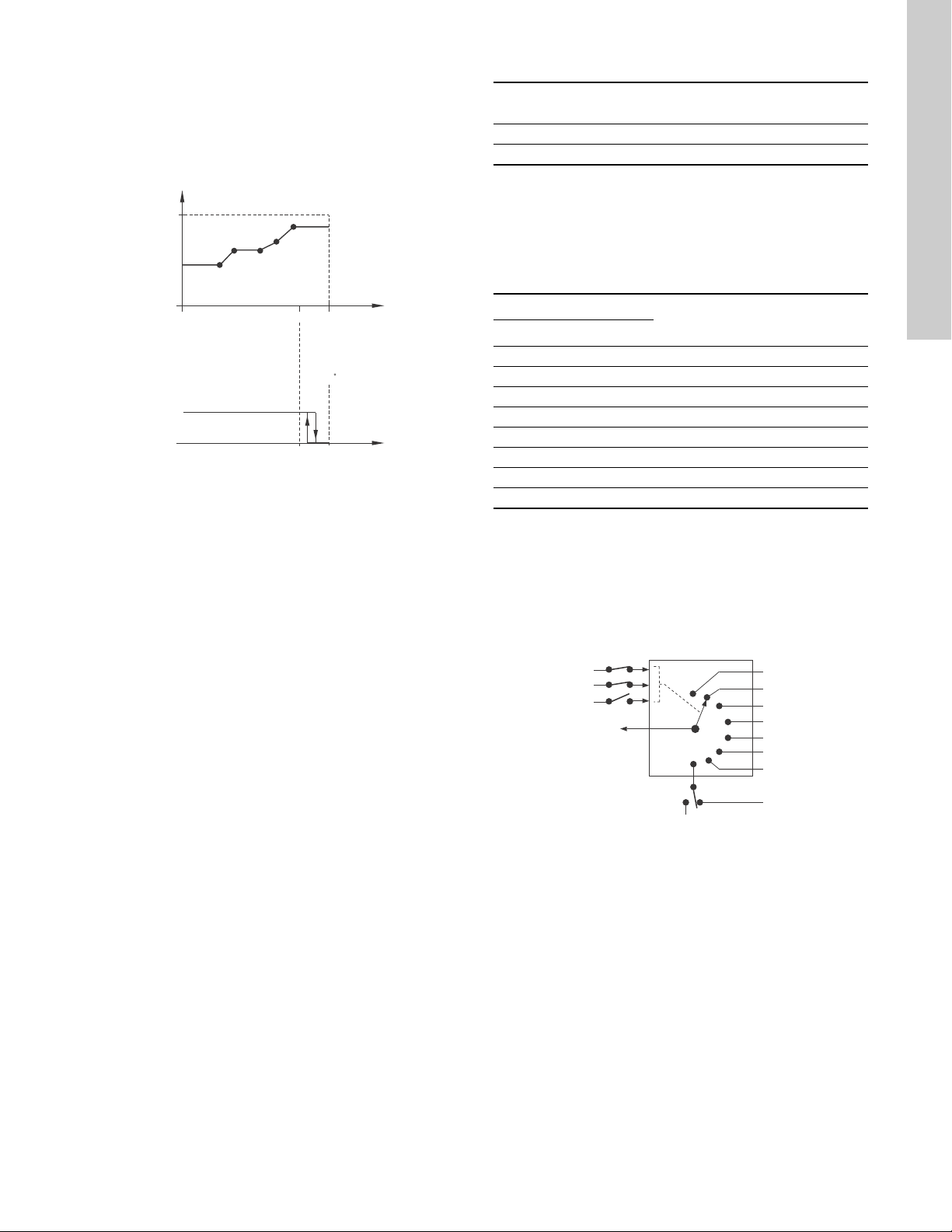
• "Influence table with Stop at Max.".
100
0
800
0.5
0
0
0
4
-50
100 %
3.5 V
5 V
10 V
20 mA
20 mA
204 C
"Setpoint influence" [%]
External
input
"Normal"
"Min." or
"Stop"
0
1
2
3
4
5
6
7
Digital input 4
Setpoint 1
Setpoint 2
Setpoint 3
Setpoint 4
Setpoint 5
Setpoint 6
Setpoint 7
Digital input 3
Digital input 2
Actual setpoint
Stop
Normal
setpoint
The setpoint is influenced by a curve made out of two to eight
points. There is a straight line between the points and a
horizontal line before the first point and after the last point. If
the input signal is above 90 %, the pump changes to operating
mode "Stop". If the input signal is reduced below 85 %, the
operating mode is changed back to "Normal". See fig. 64.
7.14 "Predefined setpoints"
Pump variant
LCSE ●
VLSE ●
You can set and activate seven predefined setpoints by
combining the input signals to digital inputs 2, 3 and 4. See the
table below.
Set the digital inputs 2, 3 and 4 to "Predefined setpoints" if all
seven predefined setpoints are to be used. You can also set one
or two of the digital inputs to "Predefined setpoints" but this limits
the number of predefined setpoints available.
"Predefined
setpoints"
English (US)
Fig. 64 "Influence table with Stop at Max." (example with five
points)
Factory setting
See section 10. Technical data.
"Digital inputs"
"Setpoint"
234
0 0 0 Normal setpoint or stop
1 0 0 "Predefined setpoint 1"
0 1 0 "Predefined setpoint 2"
1 1 0 "Predefined setpoint 3"
0 0 1 "Predefined setpoint 4"
TM06 4172 1615
1 0 1 "Predefined setpoint 5"
0 1 1 "Predefined setpoint 6"
1 1 1 "Predefined setpoint 7"
0: Open contact
1: Closed contact
Example
Figure 65 shows how you can use the digital inputs to set seven
predefined setpoints. Digital input 2 is open and digital inputs 3
and 4 are closed. If you compare with the table above, you can
see that "Predefined setpoint 6" is activated.
TM06 4269 1815
Fig. 65 Principle sketch showing how predefined setpoints
function
If all digital inputs are open, the pump stops or runs at the normal
setpoint. Set the desired action with Grundfos GO or with the
advanced control panel.
Factory setting
See section 10. Technical data.
45
Page 46

English (US)
1
2
4 4
5 6
3
A
Time [s]
7.15 "Limit-exceeded function"
Pump variant
LCSE ●
VLSE ●
This function can monitor a measured parameter or one of the
internal values such as speed, motor load or motor current. If a
set limit is reached, a selected action can take place. You can set
two limit-exceeded functions meaning that you can monitor two
parameters or two limits of the same parameter simultaneously.
The function requires setting of the following:
"Measured"
Here you set the measured parameter which is to be monitored.
"Limit"
Here you set the limit which activates the function.
"Hysteresis band"
Here you set the hysteresis band.
"Limit exceeded when"
Here you can set if you want the function to activate when the
selected parameter exceeds or drops below the set limit.
• "Above limit".
The function is activated if the measured parameter exceeds
the set limit.
• "Below limit".
The function is activated if the measured parameter drops
below the set limit.
"Action"
If the value exceeds a limit, you can set an action. You can select
the following actions:
• "No action".
The pump remains in its current state. Use this setting if you
only want to have a relay output when the limit is reached. See
section 7.9 "Signal relays" 1 and 2 ("
• "Warning/alarm".
A warning is given.
•"Stop".
The pump stops.
•"Min.".
The pump reduces speed to minimum.
•"Max.".
The pump increases speed to maximum.
"Limit-exceeded
function"
Relay outputs"
).
Detection delay
You can set a detection delay which ensures that the monitored
parameter stays above or below a set limit in a set time before the
function is activated.
Resetting delay
The resetting delay is the time from which the measured
parameter differs from the set limit including the set hysteresis
band and until the function is reset.
Example:
The function is to monitor the outlet pressure from a CRE pump.
If the pressure is below 5 bar for more than 5 seconds, a warning
must be given. If the outlet pressure is above 7 bar for more than
8 seconds, reset the limit exceeded warning.
TM06 4603 2515
Fig. 66 Limit exceeded (example)
Pos. Setting parameter Setting
1 "Measured" Outlet pressure
2 "Limit" 5 bar
3 "Hysteresis band" 2 bar
4 "Limit exceeded when" Below limit
5 "Detection delay" 5 seconds
6 "Resetting delay" 8 seconds
A "Limit exceeded function active" -
- "Action" Warning
Factory setting
See section 10. Technical data.
46
Page 47

7.16 "LiqTec" ("LiqTec function")
Q
Q
min2Qmin1
Q
min3
H
Ƹ
H
Stop pressure
Start pressure
Pump variant
LCSE ●
VLSE ●
You can enable the function of the LiqTec sensors in this display.
A LiqTec sensor protects the pump against dry running.
The function requires that a LiqTec sensor has been fitted and
connected to the pump.
When you have enabled the LiqTec function, it stops the pump if
dry running occurs. Restart the pump manually if it has been
stopped due to dry running.
"Dry running detection delay"
You can set a detection delay in order to make sure that the pump
is given a chance to start up before the LiqTec function stops the
pump due to dry running.
Range: 0-254 seconds.
Factory setting
See section 10. Technical data.
"LiqTec"
("LiqTec function")
7.17 "Stop function" ("Low-flow stop function")
"Stop function"
Pump variant
LCSE ●
VLSE ●
You can set the "Low-flow stop function" to these values:
•"Not active"
• "Energy-optimal mode"
• "High-comfort mode"
• "User-defined mode" ("Customised operating mode").
When the low-flow stop function is active, the flow is monitored. If
the flow becomes lower than the set minimum flow (Q
pump changes from continuous operation at constant pressure to
start-stop operation and stops if the flow reaches zero.
("Low-flow stop
function")
), the
min
The advantages of enabling the "Low-flow stop function" are the
following:
• no unnecessary heating of the pumped liquid
• reduced wear of the shaft seals
• reduced noise from operation.
The disadvantages of enabling the "Low-flow stop function" may
be the following:
• The delivered pressure is not completely constant as it
fluctuates between the start and stop pressures.
• The frequent starts/stops of the pump may in some
applications cause acoustic noise.
The impact of the above disadvantages very much depends on
the setting selected for the stop function.
The "High-comfort mode" setting minimizes pressure fluctuations
and acoustic noise.
Select "Energy-optimal mode" if the main priority is to reduce the
energy consumption as much as possible.
Possible settings of the stop function:
• "Energy-optimal mode"
The pump automatically adjusts the parameters for the stop
function so that the energy consumption during the start-stop
operation period is minimized.
In this case, the stop function uses the factory-set values of
the minimum flow (Q
fig. 67.
) and other internal parameters. See
min1
• "High-comfort mode":
The pump automatically adjusts the parameters for the stop
function so that the disturbances during the start-stop
operation period are minimized.
In this case, the stop function uses the factory-set values of
the minimum flow (Q
fig. 67.
) and other internal parameters. See
min2
• "User-defined mode" ("Customised operating mode"):
The pump uses the parameters set for ∆H and minimum flow
(Q
respectively for the stop function. See fig. 67.
min3)
English (US)
TM06 4267 1815
Fig. 67 Difference between start and stop pressures (∆H) and
minimum flow rate
In start-stop operation, the pressure varies between the start and
stop pressures. See fig. 67.
In "User-defined mode" ("Customised operating mode"), ∆H has
been factory-set to 10 % of the actual setpoint. ∆H can be set
within the range from 5 to 30 % of actual setpoint.
The pump changes to start-stop operation if the flow becomes
lower than the minimum flow.
The minimum flow is set in % of the nominal flow of the pump
(see the pump nameplate).
In "User-defined mode" ("Customised operating mode"), the
minimum flow has been factory-set to 10 % of nominal flow.
47
Page 48

English (US)
Caution
Pressure sensor
Diaphragm tank
Non-return
valve
Pump
Diaphragm tank
Pressure sensor
Pump Non-return valve
Factory setting
See section 10. Technical data.
"Low-flow detection"
Low flow can be detected in two ways:
1. A built-in low-flow detection function which is active if none of
the digital inputs are set for flow switch.
2. A flow switch connected to one of the digital inputs.
1. Low-flow detection function:
The pump checks the flow regularly by reducing the speed for
a short time. If there is no or only a small change in pressure,
this means that there is low flow. The speed is increased until
the stop pressure (actual setpoint + 0.5 x ΔH) is reached and
the pump stops. When the pressure has fallen to the start
pressure (actual setpoint - 0.5 x ΔH), the pump restarts.
– If the flow is higher than the set minimum flow, the pump
returns to continuous operation at constant pressure.
– If the flow is still lower than the set minimum flow (Q
min
), the
pump continues in start-stop operation until the flow is
higher than the set minimum flow (Q
higher than the set minimum flow rate (Q
). When the flow is
min
), the pump
min
returns to continuous operation.
2. Flow switch:
When the digital input is activated for more than 5 seconds
because there is low flow, the speed is increased until the
stop pressure (actual setpoint + 0.5 x ΔH) is reached, and the
pump stops. When the pressure has fallen to start pressure,
the pump restarts. If there is still no flow, the pump quickly
reaches the stop pressure and stops. If there is flow, the pump
continues operating according to the setpoint.
Operating conditions for the low-flow stop function
You can only use the stop function if the system incorporates a
pressure sensor, a non-return valve and a diaphragm tank.
Always install the non-return valve before the
pressure sensor. See figs 68 and 69.
"Set minimum flow"
Set the minimum flow (Q
) in this display. This setting
min
determines at which flow rate the system is to change from
continuous operation at constant pressure to start-stop operation.
The setting range is 5 to 30 % of rated flow.
Factory setting
See section 10. Technical data.
"Diaphragm tank volume"
The stop function requires a diaphragm tank of a certain minimum
size. Set the size of the installed tank in this display.
In order to reduce the number of start-stops per hour or to reduce
the ∆H, install a larger tank.
Install the tank immediately after the pump. The precharge
pressure must be 0.7 x actual setpoint.
Recommended diaphragm tank size:
Rated flow rate
of pump
[gpm (m
3
/h)]
0-26
(0 - 5.9)
27-105
(6.1 - 23.8)
106-176
(24.2 - 40)
177-308
(40.2 - 70.0)
309-440
(70.2 - 99.9)
441-750
(100-170)
CRE pump
1s, 1, 3 2 (7.6)
5, 10, 15 4.4 (16.7)
20, 32 14 (53.0)
45 34 (128.7)
64, 90 62 (234.7)
120, 150 86 (325.5)
Typical diaphragm
tank size
[gal (liters)]
Factory setting
See section 10. Technical data.
Fig. 68 Position of the non-return valve and pressure sensor in
Fig. 69 Position of the non-return valve and pressure sensor in
48
TM03 8582 1907TM03 8583 1907
system with suction lift operation
a system with a positive inlet pressure
Page 49

7.18 "Pipe filling function"
1. Filling phase
(constant-curve
operation)
2. Pressure build-up
phase
(constant-pressure
operation)
Pressure
Filling time Pressure
build-up
time
Time
[sec]
Filling pressure
Maximum filling time
"Setpoint"
Setpoint
ramp-up
Actual value
Pump variant
LCSE ●
VLSE ●
This function is typically used in pressure-boosting applications
and ensures a smooth startup of systems with for instance empty
pipes.
Startup takes place in two phases. See fig. 70.
1. Filling phase.
The pipes are slowly filled with water. When the pressure
sensor of the system detects that the pipes have been filled,
phase two begins.
2. Pressure build-up phase.
The system pressure is increased until the setpoint is
reached. The pressure build-up takes place over a pressure
build-up time. If the setpoint is not reached within a given
time, a warning or an alarm can be given, and the pumps can
be stopped at the same time.
"Pipe filling
function"
Setting range
• "Filling speed".
Fixed speed of the pump during the filling phase.
• "filling pressure".
The pressure that the pump must reach before the maximum
filling time.
• "max. filling time".
The time in which the pump must reach the filling pressure.
• "Max. time reaction".
Reaction of the pump if the maximum filling time is exceeded:
– warning
– alarm (pump stops).
• "Pressure build-up time".
Ramp time from when the filling pressure is reached until the
setpoint must be reached.
When you activate this function, the function always
starts when the pump has been in operating mode
"Stop" and is changed to "Normal".
Factory setting
See section 10. Technical data.
7.19 "Pulse flowmeter" ("Pulse flowmeter setup")
English (US)
Fig. 70 Filling and pressure build-up phases
Pump variant
LCSE ●
VLSE ●
You can connect an external pulse flowmeter to one of the digital
inputs in order to register the actual and accumulated flows.
Based on this, you can also calculate the specific energy.
To enable a pulse flowmeter, set one of the digital-input functions
to "Accumulated flow" and set the pumped volume per pulse. See
section 7.7 "
Factory setting
See section 10. Technical data.
TM03 9037 3207
Digital inputs"
.
"Pulse flowmeter"
("Pulse flowmeter setup")
49
Page 50

English (US)
User-set
ramp-up
User-set
ramp-down
Speed
Time
User-set
minimum
Fixed initial
ramp
Fixed final
ramp
User-set
maximum
Fixed
maximum
0
7.20 "Ramps"
7.21 "Standstill heating"
Pump variant "Ramps"
LCSE ●
VLSE ●
The ramps determine how quickly the pump can accelerate and
decelerate during start-stop or setpoint changes.
You can set the following:
• acceleration time, 0.1 to 300 seconds
• deceleration time, 0.1 to 300 seconds.
The times apply to the acceleration from 0 rpm to maximum
(fixed) speed and the deceleration from maximum (fixed) speed
to 0 rpm, respectively.
At short deceleration times, the deceleration of the pump may
depend on load and inertia as there is no possibility of actively
braking the pump.
If the power supply is switched off, the deceleration of the pump
only depends on load and inertia.
Fig. 71 "Ramp-up" and "Ramp-down"
Factory setting
See section 10. Technical data.
Pump variant "Standstill heating"
LCSE ●
VLSE ●
You can use this function to avoid condensation in humid
environments. When you set the function to "Active" and the
pump is in operating mode "Stop", a low AC voltage is applied to
the motor windings. The voltage is not high enough to make the
motor rotate but ensures that sufficient heat is generated to avoid
condensation in the motor including the electronic parts in the
drive.
Remember to remove the drain plugs and fit a cover
over the motor.
Factory setting
See section 10. Technical data.
7.22 "Motor bearing monitoring"
You can set the motor bearing monitoring function to these
values:
•"Active"
•"Not active".
When the function is set to "Active", a counter in the controller
starts counting the mileage of the bearings.
TM03 9439 0908
Factory setting
See section 10. Technical data.
The counter continues counting even if the function is
changed to "Not active", but a warning will not be
given when it is time for replacement or relubrication.
When the function is changed to "Active" again, the
accumulated mileage is again used to calculate the
replacement or relubrication time.
50
Page 51

7.23 "Service"
7.24 "Number" ("Pump number")
"Motor bearing monitoring" must be activated in order
for the motor to indicate that the bearings must be
replaced or relubricated. See section 7.22 "
bearing monitoring"
For motors of 10 hp (7.5 kW) and below, it is not possible to
relubricate the bearings.
Bearings on motors of 15 hp (11 kW) and above can be
relubricated.
"Time to next service" ("Motor bearing service"")
This display shows when to replace or relubricate the motor
bearings. The controller monitors the operating pattern of the
motor and calculates the period between bearing replacements or
relubrications.
Displayable values:
• "in 2 years"
• "in 1 year"
• "in 6 months"
• "in 3 months"
• "in 1 month"
• "in 1 week"
•"Now".
"Bearing replacements"
This display shows the number of bearing replacements that have
been done during the lifetime of the motor.
"Bearings replaced" ("Motor bearing maintenance")
When the bearing monitoring function is active, the controller
gives a warning when the motor bearings are due to be replaced.
When you have replaced the motor bearings, press [Bearings
replaced].
"Bearing relubrications"
The following applies only for 15 hp (11 kW) motors.
This display shows the number of bearing relubrications that have
been done since the last bearing replacement.
"Bearings relubricated" ("Motor bearing maintenance")
The following applies only for 15 hp (11 kW) motors.
When the bearing monitoring function is active, the controller
gives a warning when the motor bearings are due to be
relubricated.
When you have relubricated the motor bearings, press [Bearings
relubricated].
The factory-set interval between relubrications is stated on the
bearing nameplate which is placed on the motor. The
relubrication interval can be changed by a Grundfos service
technician.
It is possible to relubricate the bearings five times according to
the preset interval. When the preset interval has been reached
after the fifth relubrication, a warning will be given to replace the
bearings.
.
Motor
Pump variant
LCSE ●
VLSE ●
You can allocate a unique number to the pump. This makes it
possible to distinguish between pumps in connection with
GENIbus communication.
Factory setting
See section 10. Technical data.
"Number"
("Pump number")
7.25 "Radio communication" ("Enable/disable radio
comm.")
Pump variant
LCSE ●
VLSE ●
You can set the radio communication to either enabled or
disabled. You can use this function in areas where radio
communication is not allowed.
IR communication remains active.
Factory setting
See section 10. Technical data.
"Radio communication"
("Enable/disable radio comm.")
7.26 "Language"
Pump variant "Language"
LCSE ●
VLSE ●
This menu is only available in the advanced control panel.
In this menu, you select the desired language. A number of
languages is available.
Factory setting
See section 10. Technical data.
English (US)
51
Page 52

English (US)
7.27 "Date and time" ("Set date and time")
7.29 "Buttons on product" ("Enable/disable settings")
Pump variant
LCSE ●
VLSE ●
The availability of this menu depends on the functional module
fitted in the pump:
Function (terminal)
"Date and time" - ●
* See section 5.2.1 Identification of functional module.
You can set date and time as well as how you want them to be
viewed in the display:
• "Select date format":
"YYYY-MM-DD"
"DD-MM-YYYY"
"MM-DD-YYYY".
• "Select time format":
"HH:MM 24-hour clock"
"HH:MM am/pm 12-hour clock".
•"Set date"
•"Set time".
Factory setting
See section 10. Technical data.
"Date and time"
("Set date and time")
FM 200*
(standard)
FM 300*
(advanced)
7.28 "Unit configuration" ("Units")
Pump variant
LCSE ●
VLSE ●
In this menu, you can select between SI and US units. The setting
can made generally for all parameters or you can customize for
each parameter.
Factory setting
See section 10. Technical data.
"Unit configuration"
("Units")
Pump variant
LCSE ●
VLSE ●
In this display, you can disable the possibility of making settings
for protective reasons.
Grundfos GO
If you set the buttons to "Not active" the buttons on the standard
control panel are disabled. If you set the buttons to "Not active"
on pumps fitted with an advanced control panel, see below.
Advanced control panel
If you have disabled the settings, you can still use the buttons to
navigate through the menus, but you cannot make changes in the
"Settings" menu.
When you have disabled the possibility to make settings, the
symbol appears in the display.
Advanced control panel:
To unlock the motor and allow settings, press and
simultaneously for at least 5 seconds.
Standard control panel:
The button always remains active but you can
only unlock all other buttons on the motor with
Grundfos GO.
Factory setting
See section 10. Technical data.
"Buttons on product"
("Enable/disable settings")
7.30 "Delete history"
Pump variant "Delete history"
LCSE ●
VLSE ●
This menu is only available in the advanced control panel.
In this menu, you can delete the following historic data:
• "Delete operating log".
• "Delete energy consumption".
52
Page 53

7.31 "Define Home display"
7.34 "Recall settings" ("Recall stored settings")
Pump variant "Define Home display"
LCSE ●
VLSE ●
This menu is only available in the advanced control panel.
In this menu, you can set the "Home" display to show up to four
user-defined parameters.
Factory setting
See section 10. Technical data.
7.32 "Display settings"
Pump variant "Display settings"
LCSE ●
VLSE ●
This menu is only available in the advanced control panel.
In this menu, you can adjust the display brightness and set
whether or not the display is to turn off if no buttons have been
activated for a period of time.
Factory setting
See section 10. Technical data.
7.33 "Store settings" ("Store actual settings")
Pump variant
LCSE ●
VLSE ●
Grundfos GO
In this menu, you can store the actual settings for later use in the
same pump or in other pumps of the same type.
Advanced control panel
In this menu, you can store the actual settings for later use in the
same pump.
"Store settings"
("Store actual settings")
Pump variant
LCSE ●
VLSE ●
Grundfos GO
In this menu, you can recall stored settings from a number of
previously stored settings that the pump then uses.
Advanced control panel
In this menu, you can recall the last stored settings that the pump
then uses.
7.34.1 "Undo"
Pump variant "Undo"
LCSE ●
VLSE ●
This menu is only available in Grundfos GO.
In this display, you can undo all settings that have been made
with Grundfos GO in the current communication session. Once
you have recalled settings, you cannot undo.
"Recall settings"
("Recall stored settings")
7.35 "Pump name"
Pump variant "Pump name"
LCSE ●
VLSE ●
This menu is only available in Grundfos GO.
In this display, you can give the pump a name. In this way, you
can easily identify the pump when connecting with Grundfos GO.
English (US)
53
Page 54

English (US)
7.36 "Connection code"
7.37 "Run start-up guide"
Pump variant "Connection code"
LCSE ●
VLSE ●
This menu is only available in Grundfos GO.
You can set a connection code to avoid having to press the
connection button each time and to restrict remote access to the
product.
Setting the code in the product using Grundfos GO
1. Connect Grundfos GO to the product.
2. In the product dashboard, select "Settings".
3. Choose "Connection code".
4. Enter the wanted code and press [OK].
The code must be a character string (ASCII).
You can always change the code. The old code is not needed.
Setting the code in Grundfos GO
You can define a default connection code in Grundfos GO so that
it automatically attempts to connect to the selected product via
this code.
When you select a product with the same connection code in
Grundfos GO, Grundfos GO automatically connects to the
product and you do not have to press the connection button on
the module.
Define the default code in Grundfos GO in this way:
1. In the main menu, under "General", select "Settings".
2. Choose "Remote".
3. Enter the connection code in the field "Preset connection
code". The field now says "Connection code set".
You can always change the default connection code by pressing
[Delete] and entering a new one.
If Grundfos GO fails to connect and ask you to press the
connection button on the product, it means that the product has
no connection code or has a different connection code. In this
case, you can only establish connection via the connection
button.
Pump variant
LCSE ●
VLSE ●
This menu is only available in the advanced control panel.
The startup guide automatically starts when you start the pump
for the first time.
You can always run the startup guide later via this menu.
The startup guide guides you through the general settings of the
pump.
•"Language". See section 7.26 "
• "Select date format".*
See section 7.27 "Date and time" ("Set date and time").
•"Set date".*
See section 7.27 "Date and time" ("Set date and time").
• "Select time format".*
See section 7.27 "Date and time" ("Set date and time").
•"Set time".*
See section 7.27 "Date and time" ("Set date and time").
•"Setting of pump"
– "Go to Home"
– "Run with Constant curve"/"Run with Constant pressure".
See section 7.4 "Control mode".
– "Go to "Assisted pump setup".
See section 7.41 "Assisted pump setup".
– "Return to factory settings".
* This function applies only for pumps fitted with advanced
functional module, FM 300. For further information, see
section 5.2.1 Identification of functional module.
Language"
"Run start-up
guide"
.
7.38 "Alarm log"
This menu contains a list of logged alarms from the product. The
log shows the name of the alarm, when the alarm occurred and
when it was reset.
After setting a connection code, switch off the product
until the light in Grundfos Eye turns off before you
can use the new connection code.
54
Page 55

7.39 "Warning log"
This menu contains a list of logged warnings from the product.
The log shows the name of the warning, when the warning
occurred and when it was reset.
7.40 "Assist"
This menu consist of a number of different assist functions which
are small guides that take you through the steps needed to set
the pump.
7.41 "Assisted pump setup"
Pump variant "Assisted pump setup"
LCSE ●
VLSE ●
This menu guides you through the following:
"Setting of pump"
• Selection of control mode. See page 31.
• Configuration of feedback sensors.
• Adjusting the setpoint. See page 31.
•"Controller settings". See page 41.
• Summary of settings.
Example of how to use the "Assisted pump setup" for setting
up the pump to constant pressure:
Grundfos GO
1. Open the "Assist" menu.
2. Select "Assisted pump setup".
3. Select control mode "Constant pressure" ("Const. pressure").
4. Read the description for this control mode.
5. Select which analog input to use as sensor input.
6. Select sensor function according to where the sensor is
installed in the system. See fig. 50 on page 36.
7. Select electrical input signal according to the sensor
specifications.
8. Select measuring unit according to the sensor specifications.
9. Set the minimum and maximum sensor range values
according to the sensor specifications.
10. Set the desired setpoint.
11. Set the gain and integral time of the controller. See section
7.11 "Controller" ("
12. Type the desired pump name.
13. Check the summary of settings and confirm them.
Controller settings"
).
Advanced control panel
1. Open the "Assist" menu.
2. Select "Assisted pump setup".
3. Select control mode "Const. pressure".
4. Select which analog input to be used as sensor input.
5. Select the measured parameter which is to be controlled. See
fig. 50 on page 36.
6. Select measuring unit according to the sensor specifications.
7. Set the minimum and maximum sensor range values
according to the sensor specifications.
8. Select electrical input signal according to the sensor
specifications.
9. Set the desired setpoint.
10. Set the gain and integral time of the controller. See section
7.11 "Controller" ("
11. Check the summary of settings and confirm them by pressing
[OK].
Controller settings"
).
7.42 "Setup, analog input"
Pump variant "Setup, analog input"
LCSE ●
VLSE ●
This menu is only available in the advanced control panel.
This menu guides you through the following:
"Setup, analog input"
•"Analog inputs" 1 to 3. See page 36.
• "Pt100/1000 input" 1 and 2. See page 37.
• "Adjusting the setpoint". See page 31.
• "Summary".
7.43 "Setting of date and time"
Pump variant "Setting of date and time"
LCSE ●
VLSE ●
This menu is only available in the advanced control panel.
Whether this menu is available or not, depends on the functional
module fitted in the pump:
Function (terminal)
"Setting of date and time" - ●
* See section 5.2.1 Identification of functional module.
This menu guides you through the following:
• "Select date format". See section 7.27 "Date and time" ("Set
date and time").
•"Set date". See section 7.27 "Date and time" ("Set date and
time").
• "Select time format". See section 7.27 "Date and time" ("Set
date and time").
•"Set time". See section 7.27 "Date and time" ("Set date and
time").
FM 200*
(standard)
FM 300*
(advanced)
English (US)
55
Page 56

English (US)
7.44 "Multi-pump setup" ("Setup of multi-pump system")
"Multi-pump setup"
Pump variant
LCSE ●
VLSE ●
The multipump function enables the control of two pumps
connected in parallel without the use of external controllers. The
pumps in a multipump system communicate with each other via
the wireless GENIair connection or the wired GENI connection.
You can set a multipump system via the master pump, that is the
first selected pump.
If two pumps in the system are configured with an outlet-pressure
sensor, they can all function as master pumps and take over the
master pump function if the other should fail. This provides
additional redundancy in the multipump system.
The multipump functions are described in the following sections.
7.44.1 "Alternating operation"
Alternating operation functions as a duty/standby operating mode
and is possible with two pumps of same size and type connected
in parallel. The main purpose of the function is to ensure an even
amount of running hours and to ensure that the standby pump
starts if the duty pump stops due to an alarm.
Each pump requires a non-return valve in series with the pump.
You can choose between two alternating operation modes:
• "Alternating operation, time"
Change from one pump to the other is based on time.
• "Alternating operation, energy"
Change from one pump to the other is based on energy
consumption.
If the duty pump fails, the other pump starts.
7.44.2 "Backup operation"
Backup operation is possible with two pumps of same size and
type connected in parallel. Each pump requires a non-return
valve in series with the pump.
One pump is operating continuously. The backup pump is
operated for a short time each day to prevent seizing up. If the
duty pump stops due to a fault, the backup pump starts.
("Setup of multi-pump
system")
7.44.3 Setting up a multipump system
You can set a multipump system in the following ways:
• Grundfos GO and wireless pump connection
• Grundfos GO and wired pump connection
• Advanced control panel and wireless pump connection
• Advanced control panel and wired pump connection
See step-by-step descriptions below.
Grundfos GO and wireless pump connection
1. Power on both pumps.
2. Establish contact to one of the pumps with Grundfos GO.
3. Set the needed analog and digital inputs via Grundfos GO
according to the connected equipment and the required
functionality. See section 7.41 "Assisted pump setup".
4. Assign a pump name to the pump using Grundfos GO. See
section 7.35 "Pump name".
5. Disconnect Grundfos GO from the pump.
6. Establish contact to the other pump.
7. Set the needed analog and digital inputs via Grundfos GO
according to the connected equipment and the required
functionality. See section 7.41 "Assisted pump setup".
8. Assign a pump name to the pump using Grundfos GO. See
section 7.35 "Pump name".
9. Select the "Assist" menu and choose "Setup of multi-pump
system".
10. Select the desired multipump function. See section
7.44.1 "Alternating operation" and 7.44.2 "Backup operation"
above.
11. Press [>] to continue.
12. Set the time for pump changeover, that is the time at which
the alternation between the two pumps is to take place.
This step applies only if you have selected
"Alternating operation, time" and if the motors are
fitted with FM 300.
13. Press [>] to continue.
14. Select "Radio" as the communication method to be used
between the two pumps.
15. Press [>] to continue.
16. Press "Select pump 2".
17. Select the pump from the list.
56
Use the [OK] or button to identify the pump.
18. Press [>] to continue.
19. Confirm the setting by pressing [Send].
20. Press [Finish] in the "Setup complete" dialog box.
21. Wait for the green indicator light in the middle of Grundfos Eye
to light up.
Page 57

Grundfos GO and wired pump connection
1. Connect the two pumps with each other with a 3-core
screened cable between the GENIbus terminals A, Y, B.
2. Power on both pumps.
3. Establish contact to one of the pumps with Grundfos GO.
4. Set the needed analog and digital inputs via Grundfos GO
according to the connected equipment and the required
functionality. See section 7.41 "Assisted pump setup".
5. Assign a pump name to the pump using Grundfos GO. See
section 7.35 "Pump name".
6. Assign pump number 1 to the pump. See section
7.24 "Number" ("Pump number").
7. Disconnect Grundfos GO from the pump.
8. Establish contact to the other pump.
9. Set the needed analog and digital inputs via Grundfos GO
according to the connected equipment and the required
functionality. See section 7.41 "Assisted pump setup".
10. Assign a pump name to the pump using Grundfos GO. See
section 7.35 "Pump name".
11. Assign pump number 2 to the pump. See section
7.24 "Number" ("Pump number").
12. Select the "Assist" menu and choose "Setup of multi-pump
system".
13. Select the desired multipump function. See section
7.44.1 "Alternating operation" and 7.44.2 "Backup operation"
above.
14. Press [>] to continue.
15. Set the time for pump changeover, that is the time at which
the alternation between the two pumps is to take place.
This step applies only if you have selected
"Alternating operation, time" and if the motors are
fitted with FM 300.
Advanced control panel and wireless pump connection
1. Power on both pumps.
2. On both pumps, set the analog and digital inputs according to
the connected equipment and the required functionality. See
section 7.41 "Assisted pump setup".
3. Select the "Assist" menu on one of the pumps and choose
"Setup of multi-pump system".
4. Press [>] to continue.
5. Select "Wireless"" as the communication method to be used
between the two pumps.
6. Press [>] to continue.
7. Select the desired multipump function. See section
7.44.1 "Alternating operation" and 7.44.2 "Backup operation"
above.
8. Press [>] three times to continue.
9. Press [OK] to search for other pumps.
The green indicator light in the middle of Grundfos Eye
flashes on the other pumps.
10. Press the connect button on the pump which is to be added to
the multipump system.
11. Press [>] to continue.
12. Set the time for pump changeover, that is the time at which
the alternation between the two pumps is to take place.
This step applies only if you have selected
"Alternating operation, time" and if the motors are
fitted with FM 300.
13. Press [>] to continue.
14. Press [OK] to confirm the setting.
The multipump function icons appear in the bottom of the
control panels.
English (US)
16. Press [>] to continue.
17. Select "BUS cable" as the communication method to be used
between the two pumps.
18. Press [>] to continue.
19. Press "Select pump 2".
20. Select the pump from the list.
Use the [OK] or button to identify the pump.
21. Press [>] to continue.
22. Confirm the setting by pressing [Send].
23. Press [Finish] in the "Setup complete" dialog box.
24. Wait for the green indicator light in the middle of Grundfos Eye
to light up.
57
Page 58

English (US)
Advanced control panel and wired pump connection
1. Connect the two pumps with each other with a 3-core
screened cable between the GENIbus terminals A, Y, B.
2. Set the needed analog and digital inputs according to the
connected equipment and the required functionality. See
section 7.41 "Assisted pump setup".
3. Assign pump number 1 to the first pump. See section
7.24 "Number" ("Pump number").
4. Assign pump number 2 to the other pump. See section
7.24 "Number" ("Pump number").
5. Select the "Assist" menu on one of the pumps and choose
"Setup of multi-pump system".
6. Press [>] to continue.
7. Select "Wired GENIbus" as the communication method to be
used between the two pumps.
8. Press [>] twice to continue.
9. Select the desired multipump function. See section
7.44.1 "Alternating operation" and 7.44.2 "Backup operation"
above.
10. Press [>] to continue.
11. Press [OK] to search for other pumps.
12. Select the pump from the list.
13. Press [>] to continue.
14. Set the time for pump changeover, that is the time at which
the alternation between the two pumps is to take place.
Disabling a multipump system via Grundfos GO
1. Select the "Assist" menu.
2. Select "Setup of multi-pump system".
3. Select "Disable".
4. Press [>] to continue.
5. Confirm the setting by pressing [Send].
6. Press [Finish].
Disabling a multipump system via advanced control panel
1. Select the "Assist" menu.
2. Select "Setup of multi-pump system".
3. Press [>] to continue.
4. Confirm "No multi-pump function" by pressing [OK].
5. Press [>] to continue.
6. Press [OK] to confirm.
7.45 "Description of control mode"
This menu is only available in the advanced control panel.
This menu describes each of the possible control modes. See
also section 7.4 "Control mode".
7.46 "Assisted fault advice"
This menu gives guidance and corrective actions in case of pump
failures.
This step applies only if you have selected
"Alternating operation, time" and if the motors are
fitted with FM 300.
15. Press [>] to continue.
16. Press [OK] to confirm the setting.
The multipump function icons appear in the bottom of the
control panels.
58
Page 59

8. Description of settings
8.1 Priority of settings
You can always set the pump to stop by pressing on the pump
control panel. When the pump is not in "Stop" mode, you can
always set the pump to stop by continuously pressing .
Furthermore, you can set the pump to maximum speed by
continuously pressing . You can always set the pump to
operation at maximum speed or to stop with Grundfos GO.
If two or more functions are enabled at the same time, the pump
operates according to the function with the highest priority.
Example: If you have set the pump to maximum speed via the
digital input, the pump control panel or Grundfos GO can only set
the pump to "Manual" or "Stop".
The priority of the settings appears from the table below:
Priority Start-stop button Grundfos GO or control panel on pump Digital input Bus communication
1 "Stop"
2 "Stop"*
3 "Manual"
4 "Max. speed"*
5 "Stop"
6 "Stop"
7 "Max. speed"
8 "Min. speed"
9 "Start"
English (US)
10 "Max. speed"
11 "Min. speed"
12 "Min. speed"
13 "Start"
14 "Start"
* If the bus communication is interrupted, the pump resumes its
previous operating mode, for example "Stop", selected with
Grundfos GO or the pump control panel.
59
Page 60

English (US)
8.2 Factory settings
● Function is enabled.
❍ Function is disabled.
- Function is not available.
VLSE
Settings
"Setpoint" 75 % of sensor range 75 % of sensor range 75 % of sensor range 31
"Operating mode" "Normal" "Normal" "Normal" 31
"Control mode" "Constant pressure" "Constant pressure" "Constant pressure" 31
"Pipe filling function" "Not active" "Not active" "Not active" 49
"Buttons on product" "Active" "Active" "Active" 52
"Stop function" ("Low-flow stop function") "Not active" "Not active" "Not active" 47
"Controller" ("Controller settings") ●●●
"Kp" 0.5 0.5 0.5
"Operating range" 50-100 % 50-100 % 50-100 % 42
"Ramps"
"Ramp-down" 3 seconds 3 seconds 3 seconds
"Number" ("Pump number") - - - 51
"Radio communication" "Active" "Active" "Active" 51
"Analog input 1" "4-20 mA" "Not active" "Not active"
"Analog input 3" "Not active" "Not active" "Not active"
"Pt100/1000 input 1" "Not active" "Not active" "Not active"
"Pt100/1000 input 2" "Not active" "Not active" "Not active"
"Digital input 1" "External stop" "External stop" "External stop"
"Digital input 2" "Not active" "Not active" "Not active"
"Digital in/output 3" "Not active" "Not active" "Not active"
"Digital in/output 4" "Not active" "Not active" "Not active"
"Pulse flowmeter" ❍❍❍49
"Predefined setpoints" 0 psi / 0 bar 0 % 0 % 45
"Analog output" "Speed" "Speed" Speed 40
"External setpoint function" "Not active" "Not active" "Not active" 42
"Signal relay 1" "Alarm" "Alarm" "Alarm"
"Signal relay 2" "Running" "Running" "Running"
"Limit 1 exceeded" "Not active" "Not active" "Not active"
"Limit 2 exceeded" "Not active" "Not active" "Not active"
"LiqTec" "Not active" "Not active" "Not active"
"Detection delay time" 40 seconds 40 seconds 40 seconds
"Standstill heating" "Not active" "Not active" "Not active" 50
"Motor bearing monitoring" "Not active" "Not active" "Not active" 50
"Pump name" - - - 53
"Connection code" - - - 54
"Unit configuration" US US US 52
With factory-fitted
sensor
Without
factory-fitted sensor
LCSE
Function
description on
page
41"Ti" 0.5 0.5 0.5
50"Ramp-up" 1 second 1 second 1 second
36"Analog input 2" "Not active" "Not active" "Not active"
37
37
38
39
46
47
60
Page 61

9. Servicing the product
DANGER
Electric shock
Death or serious personal injury
- Switch off the power supply to the motor and to the
signal relays. Wait at least 5 minutes before
starting any work on the motor. Make sure that the
power supply cannot be accidentally switched on.
DANGER
Magnetic field
Death or serious personal injury
- Do not handle the motor or rotor if you have a
pacemaker.
9.1 Motor
For servicing the product, download the service instructions for
the motor by using the following link or QR code.
http://net.grundfos.com/qr/i/98413121
English (US)
QR98413121
9.2 Pump
Service documentation is available in Grundfos Product Center
(http://product-selection.grundfos.com/).
If you have any questions, please contact the nearest Grundfos
company or service workshop.
9.3 Cleaning the product
WARNING
Electric shock
Death or serious personal injury
- Switch off the power supply to the motor and to the
signal relays. Check that the terminal box cover is
intact before spraying water on the product.
In order to avoid condensation in the motor, let the motor cool
down before spraying it with cold water.
61
Page 62

English (US)
1
0.99
0.98
0.97
0.96
0.95
0.94
0.93
0.92
0.91
0.90
0.89
0.88
0
0
3281 3937 4593 5249 5906 6562 7218
[ft]
P2
[%]
10. Technical data
10.1 Operating conditions
10.1.1 Maximum number of starts and stops
The number of starts and stops via the power supply must not
exceed four times per hour.
When switched on via the power supply, the pump starts after
approximately 5 seconds.
If a higher number of starts and stops is desired, use the input for
external start-stop when starting and stopping the pump.
When started via an external on/off switch, the pump starts
immediately.
10.1.2 Ambient temperature
Ambient temperature during storage and transportation
Minimum: -22 °F (-30 °C)
Maximum: 140 °F (60 °C).
Ambient temperature during operation
Minimum: -4 °F (-20 °C)
Maximum: 122 °F (50 °C).
The motor can operate with the rated power output (P2) at 122 °F
(50 °C), but continuous operation at higher temperatures reduces
the expected product life. If the motor is to operate at ambient
temperatures between 122 °F (50 °C) and 140 °F (60 °C), select
an oversized motor. Contact Grundfos for further information.
10.1.3 Installation altitude
If the motor is installed above 6560 ft (2000 m), it
does not comply with SELV/PELV classification.
Installation altitude is the height above sea level of the installation
site.
Motors installed up to 3280 ft (1000 meters) above sea level can
be loaded 100 %.
• Motors installed more than 3280 ft (1000 meters) above sea
level must not be fully loaded due to the low density and
consequent low cooling effect of the air. See fig. 72.
10.1.4 Humidity
Maximum humidity: 95 %.
If the humidity is constantly high and above 85 %, open the drain
holes in the drive-end flange. See section Fig. 2 Examples of
covers (not supplied by Grundfos).
10.1.5 Motor cooling
To ensure cooling of motor and electronics, observe the following:
• Position the motor in such a way that adequate cooling is
ensured. See section 4.1.5 Ensuring motor cooling.
• The temperature of the cooling air must not exceed 122 °F (50
°C).
Keep cooling fins and fan blades clean.
10.2 Megging
Do not meg an installation incorporating MLE motors, as the
built-in electronics may be damaged.
10.3 Technical data, single-phase motors
10.3.1 Supply voltage
• 1 x 200-240 V - 10 %/+ 10 %, 50/60 Hz, PE.
Check that the supply voltage and frequency correspond to the
values stated on the nameplate.
Recommended fuse size
Motor size
Hp [kW]
0.33 - 1 (0.25 - 0.75) 6 10
1 1/2 - 2 (1.1 - 1.5) 10 16
You can use standard as well as quick-blow or slow-blow fuses.
10.3.2 Leakage current
Ground leakage current less than 3.5 mA, AC.
Ground leakage current less than 10 mA, DC.
The leakage currents are measured in accordance with EN
61800-5-1:2007.
Minimum
[A]
Maximum
[A]
TM06 9374 2117
Fig. 72 Derating of motor output power (P2) in relation to
altitude above sea level
62
Page 63

10.4 Technical data, three-phase motors
10.4.1 Supply voltage
• 3 x 380-500 V - 10 %/+ 10 %, 50/60 Hz, PE.
Check that the supply voltage and frequency correspond to the
values stated on the nameplate.
Recommended fuse size
Motor size
[Hp (kW)]
0.33 - 1 1/2 (0.25 - 1.1) 6 6
2 (1.5) 6 10
3 (2.2) 6 16
5 (4) 13 16
7 1/2 (5.5) 16 32
10 (7.5) 20 32
15 (11) 32 32
Standard as well as quick-blow or slow-blow fuses may be used.
10.4.2 Leakage current (AC)
Speed
[min
-1
]
Power
[Hp (kW)]
0.33 - 3
(0.25 - 2.2)
2900-4000
5 - 7 1/2
(4 - 5 1/2)
10 - 15
(7 1/2 - 11)
0.33 - 3
(0.25 - 2.2)
4000-5900
5 - 7 1/2
(4 - 5.5)
10-15
(7.5 - 11)
The leakage currents are measured in accordance with EN
61800-5-1:2007.
Minimum
[A]
Power supply
voltage
[V]
≤ 400 < 3.5
> 400 < 5
≤ 400 < 3.5
> 400 < 3.5
≤ 400 < 3.5
> 400 < 5
≤ 400 < 3.5
> 400 < 5
≤ 400 < 3.5
> 400 < 3.5
≤ 400 < 3.5
> 400 < 5
Maximum
[A]
Leakage
current
[mA]
10.5 Inputs/outputs
Ground reference
All voltages refer to ground. All currents return to ground.
Absolute maximum voltage and current limits
Exceeding the following electrical limits may result in severely
reduced operating reliability and motor life:
Relay 1:
Maximum contact load: 250 VAC, 2 A or 30 VDC, 2 A.
Relay 2:
Maximum contact load: 30 VDC, 2 A.
GENI terminals: -5.5 to 9.0 VDC or less than 25 mADC.
Other input/output terminals: -0.5 to 26 VDC or less than 15
mADC.
Digital inputs, DI
Internal pull-up current greater than 10 mA at V
Internal pull-up to 5 VDC (currentless for V
Certain low logic level: V
Certain high logic level: V
less than 1.5 VDC.
i
greater than 3.0 VDC.
i
Hysteresis: No.
2
Screened cable: 0.5 - 1.5 mm
, 28-16 AWG.
Maximum cable length: 1640 ft (500 m).
Open-collector digital outputs, OC
Current sinking capability: 75 mADC, no current sourcing.
Load types: Resistive or/and inductive.
Low-state output voltage at 75 mADC: Maximum 1.2 VDC.
Low-state output voltage at 10 mADC: Maximum 0.6 VDC.
Overcurrent protection: Yes.
2
Screened cable: 0.5 - 1.5 mm
, 28-16 AWG.
Maximum cable length: 1640 ft (500 m).
Analog inputs, AI
Voltage signal ranges:
• 0.5 - 3.5 VDC, AL AU.
• 0-5 VDC, AU.
•0-10 VDC, AU.
Voltage signal: R
greater than 100 kΩ at 77 °F (25 °C).
i
Leak currents may occur at high operating temperatures. Keep
the source impedance low.
Current signal ranges:
• 0-20 mADC, AU.
• 4-20 mADC, AL AU.
Current signal: R
is equal 292 Ω.
i
Current overload protection: Yes. Change to voltage signal.
Measurement tolerance: - 0/+ 3 % of full scale (maximum-point
coverage).
2
Screened cable: 0.5 - 1.5 mm
, 28-16 AWG.
Maximum cable length: 1640 ft (500 m) excluding potentiometer.
Potentiometer connected to +5 V, GND, any AI:
Use maximum 10 kΩ.
Maximum cable length: 328 ft (100 m).
equal 0 VDC.
i
greater than 5 VDC).
i
English (US)
63
Page 64

English (US)
Analog output, AO
Current sourcing capability only.
Voltage signal:
• Range: 0-10 VDC.
• Minimum load between AO and GND: 1 kΩ.
• Short-circuit protection: Yes.
Current signal:
• Ranges: 0-20 and 4-20 mADC.
• Maximum load between AO and GND: 500 Ω.
• Open-circuit protection: Yes.
Tolerance: - 0/+ 4 % of full scale (maximum-point coverage).
2
Screened cable: 0.5 - 1.5 mm
, 28-16 AWG.
Maximum cable length: 1640 ft (500 m).
Pt100/1000 inputs, Pt
Temperature range:
• Minimum: -22 °F (-30 °C). 88 Ω / 882 Ω.
• Maximum: 356 °F (180 °C). 168 Ω / 1685 Ω.
Measurement tolerance: +- 2.5 °F (± 1.5 °C).
Measurement resolution: < 0.5 °F (0.3 °C).
Automatic range detection, Pt100 or Pt1000: Yes.
Sensor fault alarm: Yes.
2
Screened cable: 0.5 - 1.5 mm
, 28-16 AWG.
Use Pt100 for short wires.
Use Pt1000 for long wires.
LiqTec sensor inputs
Use Grundfos LiqTec sensor only.
2
Screened cable: 0.5 - 1.5 mm
, 28-16 AWG.
Grundfos Digital Sensor input and output, GDS
Use Grundfos Digital Sensor only.
Power supplies
+5 V:
• Output voltage: 5 VDC - 5 %/+ 5 %.
• Maximum current: 50 mADC (sourcing only).
• Overload protection: Yes.
+24 V:
• Output voltage: 24 VDC - 5 %/+ 5 %.
• Maximum current: 60 mADC (sourcing only).
• Overload protection: Yes.
Digital outputs, relays
Potential-free changeover contacts.
Minimum contact load when in use: 5 VDC, 10 mA.
2
Screened cable: 0.5 - 2.5 mm
, 28-12 AWG.
Maximum cable length: 1640 ft (500 m).
Bus input
Grundfos GENIbus protocol, RS-485.
2
Screened 3-core cable: 0.5 - 1.5 mm
, 28-16 AWG.
Maximum cable length: 1640 ft (500 m).
10.6 Other technical data
EMC (electromagnetic compatibility)
Standard used: EN 61800-3.
The table below indicates the emission category of the motor.
C1: Fulfills the requirements for residential areas.
C3: Fulfills the requirements for industrial areas.
Motor
Hp [kW]
1450-2000 min
0.33 (0.25) C1 C1
.5 (0.37) C1 C1
0.75 (0.55) C1 C1
1 (0.75) C1 C1
1.5 (1.1) C1 C1
2. (1.5) C1 C1
3 (2.2) C1 C1
5 (4) C1 C1
7.5 (5.5) C3/C1* C1
10 (7.5) C3/C1* C3/C1*
15 (11) - C3/C1*
*
C1, if equipped with an external Grundfos EMC filter.
Immunity: Fulfills the requirements for industrial areas.
Contact Grundfos for further information.
Enclosure class
Standard: IP55 (IEC 34-5).
Optional: IP66 (IEC 34-5).
Insulation class
F (IEC 85).
Standby power consumption
5-10 W.
Cable entries
Motor
[Hp (kW)]
0.5 - 3 (0.37 - 2.23) 4 x NPT 1/2"
5 - 7.5 (3.7 - 5.6) 5 x NPT 1/2"
10 - 15 (7.45 - 11.18) 1 x NPT 3/4" and 5 x NPT 1/2"
The cable entries are fitted with blind plugs from the factory.
Cable glands are not provided.
Torques
Terminal Thread size
L1, L2, L3, L, N M4 1.3 (1.8)
NC, C1, C2, NO M2.5 0.4 (0.5)
1-26 and A, Y, B M2 0.4 (0.5)
Emission category
-1
2900-4000 min
4000-5900 min
Number and size of cable entries
Maximum torque
[ft lb (Nm)]
-1
-1
64
Page 65

10.6.1 Sound pressure level
Maximum
Motor
[Hp (kW)]
0.33 - 1
(0.25 - 0.75)
1.5
(1.1)
2
(1.5)
3
(2.2)
5 (4)
7.5 (5.5)
10 (7.5)
15 (11)
The grey fields indicate that the motor is not available in this MLE
motor range.
speed
stated on
nameplate
-1
[min
]
2000
4000
5900
2000
4000
5900
2000
4000
5900
2000
4000
5900
2000
4000
5900
2000
4000
5900
2000
4000
5900
4000
5900
Speed
[min
1500 37 37
2000 43 43
3000 50 50
4000 60 60
4000 58 58
5900 68 68
1500
2000
3000 50 50
4000 60 60
4000 58 58
5900 68 68
1500
2000
3000 57 57
4000 64 64
4000 58 58
5900 68 68
1500
2000
3000
4000
4000
5900
1500
2000
3000
4000
4000
5900
1500
2000
3000
4000
4000
5900
1500
2000
3000
4000
4000
5900
3000
4000
4000
5900
Sound pressure level
ISO 3743
-1
]
1-phase
motors
[dB(A)]
3-phase
motors
37
43
42
47
48
55
57
64
58
68
48
55
61
69
64
74
58
61
61
69
64
74
58
61
66
73
69
79
66
73
69
79
11. Disposing of the product
This product or parts of it must be disposed of in an
environmentally sound way:
1. Use the public or private waste collection service.
2. If this is not possible, contact the nearest Grundfos company
or service workshop.
Dispose of the waste battery through the national collective
schemes. If in doubt, contact your local Grundfos company.
English (US)
65
Page 66

Appendix
Stop
Identification numbers
Identification numbers
Appendix
1. Installation in the USA and Canada
In order to maintain the cURus approval, follow these
additional installation instructions. The UL approval
is according to UL 1004-1.
For Canada
This product complies with the Canadian ICES-003 Class B
specifications. This Class B device meets all the requirements of
the Canadian interference-causing equipment regulations.
Cet appareil numérique de la Classe B est conforme à la norme
NMB-003 du Canada. Cet appareil numérique de la Classe B
respecte toutes les exigences du Réglement sur le matériel
brouilleur du Canada.
1.1 Electrical codes
For USA
This product complies with the Canadian Electrical Code and the
US National Electrical Code.
This product has been tested according to the national standards
for Electronically Protected Motors:
CSA 22.2 100-14:2014 (applies to Canada only).
UL 1004-1:2015 (applies to USA only).
Pour le Canada
Codes de l'électricité
Ce produit est conforme au Code canadien de l'électricité et au
Code national de l'électricité américain.
Ce produit a été testé selon les normes nationales s'appliquant
aux moteurs protégés électroniquement:
CSA 22.2 100.04: 2009 (s'applique au Canada uniquement).
UL 1004-1: Juin 2011 (s'applique aux États-Unis uniquement).
1.3 Identification numbers
For USA
Grundfos Holding A/S
Contains FCC ID: OG3-RADIOM01-2G4.
For Canada
Grundfos Holding A/S
Model: RADIOMODULE 2G4
Contains IC: 10447A-RA2G4M01.
Pour le Canada
Numéros d'identification
Grundfos Holding A/S
Modèle: RADIOMODULE 2G4
Contient IC: 10447A-RA2G4M01.
Location of identification numbers
TM05 7572 1213TM05 7573 1213
Fig. 1 Identification numbers
1.2 Radio communication
For USA
This device complies with part 15 of the FCC rules and RSS210
of IC rules.
Operation is subject to the following two conditions:
• This device may not cause interference.
• This device must accept any interference, including
interference that may cause undesired operation of the device.
Users are cautioned that changes or modifications not expressly
approved by Grundfos could void the user's authority to operate
the equipment.
Pour le Canada
Communication radio
Ce dispositif est conforme à la partie 15 des règles de la FCC et
aux normes RSS210 de l'IC.
Son fonctionnement est soumis aux deux conditions suivantes:
• Ce dispositif ne doit pas provoquer de brouillage préjudiciable.
• Il doit accepter tout brouillage reçu, y compris le brouillage
pouvant entraîner un mauvais fonctionnement.
Fig. 2 Identification numbers
66
Page 67

1.4 Electrical connection
1.4.1 Conductors
See section 7.2 Cable requirements, page 10.
1.4.2 Torques
Maximum tightening torques for the terminals can be found in
section Torques, page 64.
1.4.3 Line reactors
The maximum line reactor sizes are listed below.
Appendix
Motor
[Hp]
.50 1.5
.75 1.5
11.5
1.5 1.5
21.5
32
50.7
7.5 0.3
10 0.6
15 0.3
Short circuit current
If a short circuit occurs, the pump can be used on a mains supply
delivering not more than 5000 RMS symmetrical amperes, 600 V
maximum.
Fuses
Fuses used for motor protection must be rated for minimum
500 V.
Motors up to and including 10 hp require class K5 UL-listed fuses.
Any UL-listed fuse can be used for motors of 15 hp.
Branch circuit protection
When the pump is protected by a circuit breaker, this must be
rated for a maximum voltage of 480 V. The circuit breaker must
be of the "inverse time" type.
Overload protection
Degree of overload protection provided internally by the drive, in
percent of full-load current: 102 %.
Maximum line reactor size
[mH]
1.5 Outdoor installation
According to UL 778/C22.2 No 108-14 pumps that are intended
for outdoor use shall be marked enclosure type 3 and the product
shall be tested with rated surface temperature down to -31 °F
(-35 °C). The MLE enclosure is approved for type 3 or 4 and rated
surface temperature down to 32 °F (0 °C), thus only for indoor
use in UL 778/C22.2 No 108-14 pump applications. For ambient
temperature during operation, see section 10.1.2 Ambient
temperature.
67
Page 68

68
Page 69

GRUNDFOS Kansas City
17100 West 118th Terrace
Olathe, Kansas 66061
Phone: (913) 227-3400
Fax: (913) 227-3500
www.grundfos.us
GRUNDFOS Canada
2941 Brighton Road
Oakville, Ontario L6H 6C9 Canada
Phone: +1-905 829 9533
Telefax: +1-905 829 9512
www.grundfos.ca
GRUNDFOS México
Boulevard TLC No. 15
Parque Industrial Stiva Aeropuerto
C.P. 66600 Apodaca, N.L. México
Phone: 011-52-81-8144 4000
Fax: 011-52-81-8144 4010
www.grundfos.mx
Grundfos companies
Page 70

99364458 1117
ECM: 1220663
www.grundfos.com
www.grundfos.us
The name Grundfos, the Grundfos logo, and be think innovate are registered trademarks owned by Grundfos Holding A/S or Grundfos A/S, Denmark. All rights reserved worldwide. © Copyright Grundfos Holding A/S
 Loading...