

Page 1
Being responsible is our foundation
Thinking ahead makes it possible
Innovation is the essence
GRUNDFOS INSTRUCTIONS
VersaFlo® TP
Direct Coupled In-Line Single Stage
Circulator Pumps
Installation and operating instructions
L-TP-TL-001 10/06
PRINTED IN THE USA
www.grundfos.com
Page 2

LIMITED WARRANTY
Products manufactured by GRUNDFOS PUMPS CORPORATION (GRUNDFOS) are warranted
to the original user only to be free of defects in material and workmanship for a period
of 24 months from date of installation, but not more than 30 months from date of
manufacture. GRUNDFOS' liability under this warranty shall be limited to repairing or
replacing at GRUNDFOS' option, without charge, F.O.B. GRUNDFOS' factory or authorized
service station, any product of GRUNDFOS manufacture. GRUNDFOS will not be liable for
any costs of removal, installation, transportation, or any other charges which may arise
in connection with a warranty claim. Products which are sold but not manufactured by
GRUNDFOS are subject to the warranty provided by the manufacturer of said products and
not by GRUNDFOS' warranty. GRUNDFOS will not be liable for damage or wear to products
caused by abnormal operating conditions, accident, abuse, misuse, unauthorized alteration
or repair, or if the product was not installed in accordance with GRUNDFOS' printed
installation and operating instructions.
To obtain service under this warranty, the defective product must be returned to the
distributor or dealer of GRUNDFOS products from which it was purchased together
with proof of purchase and installation date, failure date, and supporting installation
data. Unless otherwise provided, the distributor or dealer will contact GRUNDFOS or
an authorized service station for instructions. Any defective product to be returned to
GRUNDFOS or a service station must be sent freight prepaid; documentation supporting
the warranty claim and/or a Return Material Authorization must be included if so
instructed.
U.S.A.
GRUNDFOS Pumps Corporation
17100 West 118th Terrace
Olathe, Kansas 66061
Phone: +1-913-227-3400
Telefax: +1-913-227-3500
Canada
GRUNDFOS Canada, Inc.
2941 Brighton Road
Oakville, Ontario
L6H 6C9
Phone: +1-905-829-9533
Telefax: +1-905-829-9512
Mexico
Bombas GRUNDFOS de Mexico S.A. de C.V.
Boulevard TLC No. 15
Parque Industrial Stiva Aeropuerto
C.P. 66600 Apodaca, N.L. Mexico
Phone: +1-52-81-8144 4000
Telefax: +1-52-81-8144 4010
GRUNDFOS WILL NOT BE LIABLE FOR ANY INCIDENTAL OR CONSEQUENTIAL DAMAGES,
LOSSES, OR EXPENSES ARISING FROM INSTALLATION, USE, OR ANY OTHER CAUSES. THERE
ARE NO EXPRESS OR IMPLIED WARRANTIES, INCLUDING MERCHANTABILITY OR FITNESS
FOR A PARTICULAR PURPOSE, WHICH EXTEND BEYOND THOSE WARRANTIES DESCRIBED OR
REFERRED TO ABOVE.
Some jurisdictions do not allow the exclusion or limitation of incidental or consequential
damages and some jurisdictions do not allow limitations on how long implied warranties
may last. Therefore, the above limitations or exclusions may not apply to you. This
warranty gives you specific legal rights and you may also have other rights which vary from
jurisdiction to jurisdiction.
Please leave these instructions with the pump for future reference.
Page 3

Notes
14
Contents
Page
1. Pre-Installation Checklist 4
1.1 Confirm You Have the 4
Right Pump
1.2 Check the Condition of 4
the Pump
1.3 Electrical Requirements 4
1.4 Is the Application Correct 4
for This Pump?
1.5 Read This Guide Thoroughly 5
2. Installation Procedures 5
2.1 Electrical Preparation 5
2.1.1 Terminal Box Position 5
2.1.2 Single-Phase Motors 5
2.1.3 Three-Phase Motors 5
2.1.4 Other Wiring Considerations 5
2.2 Piping Considerations 5
2.3 Installing the Pump 6
2.3.1 Pump Location 6
2.3.2 Position in Piping System 6
2.3.3 Proper Orientation 6
2.3.4 Direction of Flow for 6
Specific Applications
2.3.5 Suggested Accessories 6
2.4 Electrical Hookup 6
3. Starting the Pump the 6
First Time
3.1 Prime the Pump 6
3.1.1 In Closed/Open System 6
Where Water Source is
Above the Pump
3.1.2 In Open Systems 7
3.2 Check the Direction of 7
Rotation
3.3 Starting and Adjusting 7
4. Maintenance 7
4.1 Servicing the Pump Head 7
4.1.1 Step 1: Remove the Pump 7
Head
4.1.1.1 Assembly 8
4.1.2 Step 2: Re-Install the Pump 8
Head
4.1.3 Motor Replacement 9
4.1.3.1 Disassembly 9
Page
4.1.4 Pump Lubrication 9
4.1.5 Motor Lubrication 9
4.1.6 Lubrication Schedule 9
4.1.7 Periodic Safety Checks 9
4.1.8 Service Conditions 10
4.1.9 Rapid Cycling 10
4.1.10 Freeze Protection 10
5. Troubleshooting 10
5.1 Preliminary Checks 10
5.1.1 Supply Voltage 10
5.1.1.1 How to Measure 10
5.1.1.2 Evaluation 10
5.1.2 Current Measurement 10
5.1.2.1 How to Measure 10
5.1.2.2 Evaluation 10
5.1.3 Winding Resistance 11
5.1.3.1 How to Measure 11
5.1.3.2 Evaluation 11
5.1.4 Insulation Resistance 11
(Lead to Ground)
5.1.4.1 How to Measure 11
5.1.4.2 Evaluation 11
5.2 Diagnosing Specific Problems 12
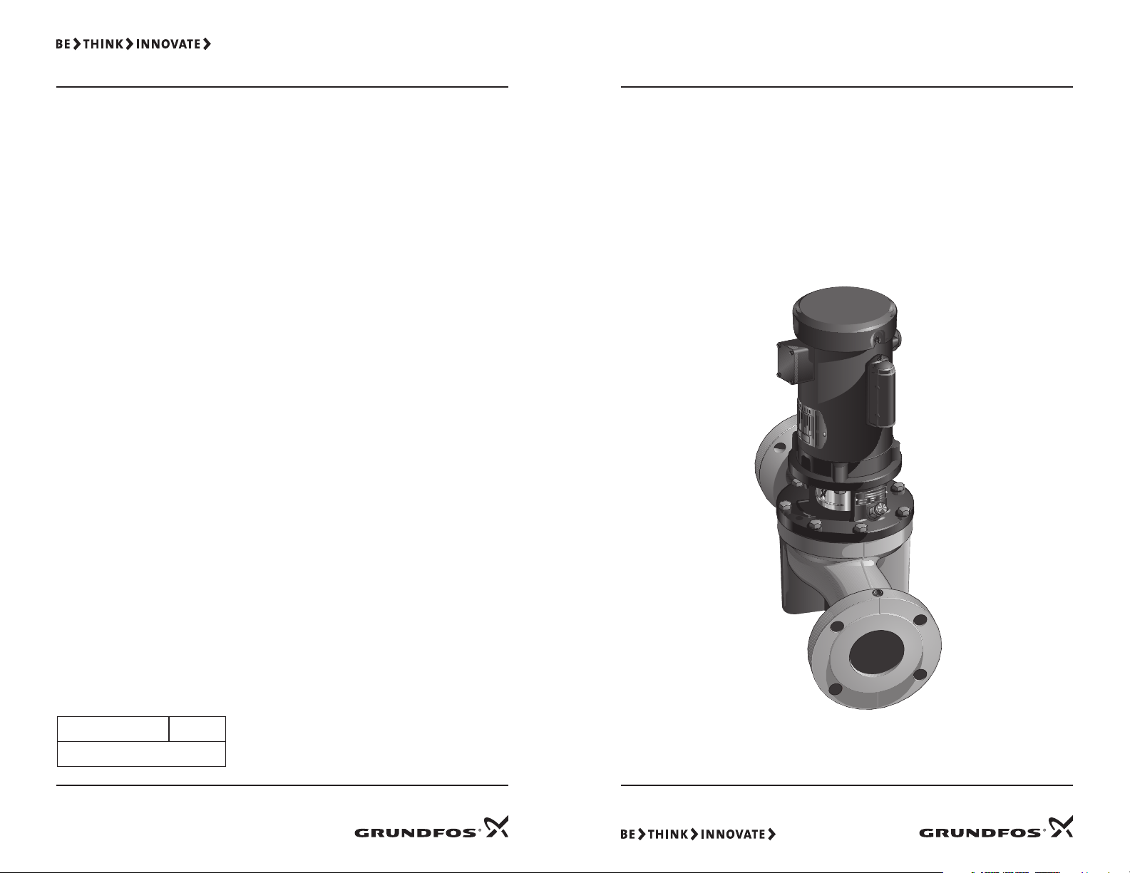
Page 4

Safety Warning
Nominal diameter (suction
& discharge) of ports in mm
Circulator Pump
Maximum head in dm
Bronze
TP 50 80 B
SPEC
FRAME
H.P.
VOLTS
AMPS
R.P.M.
HZ
SE R F
RATING
CAT. NO.
FULL LOAD EF F.
SER
P.F.
PH
DES
CLASS
CODE
LO
W
VOLTAGE
HOOKUP
HIGH
VOLTAGE
HOOKUP
®
Nameplate
Wiring
Diagram
(in this case, for
a dual voltage
motor)
Read This Booklet
This booklet is designed to help a certified
installer begin operation of and troubleshoot Grundfos VersaFlo™ TP pumps. This
booklet should be left with the owner of
the pump for future reference and information regarding its operation. Should the
owner experience any problems with the
pump, a certified professional should be
contacted.
Electrical Work
All electrical work should be performed by
a qualified electrician in accordance with
the latest edition of the National Electrical
Code, local codes and regulations.
Shock Hazard
through standing water. For this reason,
proper grounding of the pump to the power supply's grounding terminal is required
for safe installation and operation.
The ground wire should be a copper
conductor at least the size of the circuit
conductors supplying power to the motor.
Do not ground to a gas supply line.
In all installations, the above-ground metal
plumbing should be connected to the
power supply ground as described in Article
250-80 of the National Electrical Code.
1. Pre-Installation Checklist
1.1 Confirm You Have the Right Pump
• Read the pump nameplate to make sure
that it is the correct one.
• Compare the pump's nameplate data
and its performance curve (for head,
GPM, etc.) with the application in which
you plan to install it.
• Will the pump do what you expect it to
do?
• The nomenclature for the VersaFlo TP
line of Grundfos pumps is:
A faulty motor or wiring can
cause electrical shock that
could be fatal, whether
touched directly or conducted
1.2 Check the Condition of the Pump
The shipping carton your pump came in
is designed around your pump during production to prevent damage. As a precaution, it should remain in the carton until
you are ready to install it. At that point,
look at the pump and examine it for any
damage that may have occurred during
shipping. Examine any other parts of the
shipment as well for any visible damage.
1.3 Electrical Requirements
Check the motor nameplate to determine
the proper voltage, phase, and frequency
required. The voltage must be within ± 10%
of the specified motor nameplate voltage.
Dual volt-age motors must be internally
wired to match the electrical supply. A
wiring connection diagram is affixed to the
motor.
Fig. 1
1.4 Is the Application Correct for This Pump?
Compare the pump's nameplate data or its
performance curve with the application in
which you plan to install it. Will it perform
the way you want it to perform? Also,
make sure the application falls within the
following limits:
Approved applications:
• Open or closed water systems
• Glycol solutions up to 50% (requires
optional RUVV mechanical seal)
• HVAC hot and cooled water
• Condenser or cooling tower heat
exchanger circulation
• Commercial solar
• Commercial heating and fan coil
systems
• Geothermal systems
• Agricultural temperature conditioning
• Snow melting
Correct it by...
If no voltage at motor, check feeder panel for tripped circuits.
Replace blown fuses or reset circuit breaker. If new fuses blow or circuit breaker trips, the terminal box wiring must be
checked.
Replace burned heaters or reset. Inspect starter for other damage. If heater trips again, check the supply voltage and
starter holding coil.
If no voltage, check the control circuit fuses. If there is voltage, check the holding coil for shorts. Replace bad coil.
Replace worn or defective parts.
If the motor windings are open or grounded, replace the motor.
When the meter is connected, the needle should jump toward “0” ohms and slowly drift back to infinity. Replace
capacitor if defective.
Correct wiring and change leads as required.
Refill the pump, replace lug and start the pump. Long suction lines must be filled before starting the pump.
Clean and replace. Re-prime the pump.
Reduce suction lift by lowering pump, increasing suction line size or by removing high friction-loss fittings.
Repair all leaks and retighten all loose fittings.
Convert PSI to feet (PSI x 2.31 = _____ ft.). Refer to the specific pump curve for shutoff head for that pump model. If
actual head is close to curve, the pump is probably OK. If not, remove pump and inspect.
Readjust switch or replace if defective.
Readjust setting (refer to level control manufacturer’s data). Replace if defective.
Check diaphragm for leak. Check tank and piping for leaks with soap and water solution. Check air-to-water volume.
Tank volume should be approximately 10 gal. for each gpm of pump capacity. The normal air volume is 2/3 of the total
tank volume at the pump cut-in pressure.
If voltage varies more than ±10%, contact power company. Check wire sizing.
Increase heater size or adjust trip setting.
Must be within ±5%. If not, check motor and wiring.
If an open or grounded winding is found, repair or replace the motor.
Tighten loose terminals. Replace damaged wire.
If shaft does not rotate, remove pump and inspect. Disassemble and repair.
When the ohmmeter is connected to the capacitor, the needle should jump towards “0” ohms and slowly drift back to
infinity; or, with the capacitor meter the UF reading should be ±10% of capacitor rating. Replace if defective.
134
Page 5

5.2 Diagnosing Specific Problems
If the pump... It may be caused by... Check this by...
1. No power at motor. Check for voltage at terminal box.
Does not run
Pump runs, but at
a reduced capacity
or
Doesn’t deliver
water
Pump cycles too
much
Fuses blow
or
Circuit breakers
trip
2. Fuses are blown or circuit
breakers are tripped.
3. Motor starter overloads are
burned or have tripped.
4. Starter does not energize. Energize control circuit and check for voltage at the
5. Defective controls. Check all safety and pressure switches for operation.
6. Motor is defective. Turn off power. Disconnect the wiring. Measure the
7. Defective capacitor.
(Single-phase motors)
1. Wrong rotation
(Three-phase only)
2. Pump is not primed or is airbound.
3. Strainers, check valves, or foot
valves are clogged.
4. Suction lift too large. Install compound pressure gauge at the suction side
5. Suction and/or discharge piping
leaks.
6. Worn pump. Install pressure gauge, start the pump, gradually close
1. Pressure switch is not properly
adjusted or is defective.
2. Level control is not properly set
or is defective.
3. Three-phase current is unbalanced.
4. Tank is too small. Pump air into tank or diaphragm chamber. Check tank
1. High or low voltage. Check voltage at the starter panel or terminal box.
2. Starter overloads are set too low. Cycle pump and measure amperage.
3. Three-phase current is unbalanced.
4. Motor is shorted or grounded Turn off power and disconnect incoming power supply
5. Wiring or connections are faulty. Check for proper wiring and loose terminals.
6. Pump is stuck. Turn off power and manually rotate pump shaft.
7. Defective capacitor.
(Single-phase only)
Turn off power and remove fuses and check for
continuity with an ohmmeter.
Check for voltage on the line and load side of the starter.
holding coil.
Inspect contact in control devices.
lead-to-lead resistance with an ohmmeter (set at R x 1).
Measure lead-to-ground values with a megohmmeter
(R x 100K). Record the measured values.
Turn off the power, then discharge the capacitor.
Disconnect the leads and check them with an ohmmeter
(R x 100K).
Check for proper electrical connections in terminal box.
Turn pump off, close isolation valves, remove priming
plug. Check fluid level.
Remove strainer, screen, or valve and inspect.
of the pump. Start pump and compare reading to
performance data.
Pump shaft spins backwards when turned off. Air in
suction pipe.
the discharge valve and read pressure at shut-off.
Check pressure setting on switch and operation.
Check voltage across closed contacts.
Check setting and operation.
size and air volume in tank.
Check the current draw on each lead to the motor.
from terminal box. Measure winding and lead-to-ground
resistance as explained on the previous page.
Turn off power, discharge capacitor and check with
ohmmeter set at highest R value or check with capacitor
meter.
Temperature range
• Minimum +5°F (-15°C)
• Maximum +284°F (140°C)
Maximum working pressure:
145 PSI (10 bars)
1.5 Read This Guide Thoroughly
Even if you are very familiar with the
installation of this pump, a quick glance
through the remaining sections of this
guide may help you avoid a potential
problem.
For TPE pump installation, see Grundfos
Pumps publication L-EC-TL-001.
2. Installation Procedures
2.1 Electrical Preparation
2.1.1 Terminal Box Position
Before installing the pump, you must determine the most convenient position for
the terminal box, which can be rotated in
90° increments. To rotate the terminal box,
remove the four bolts securing the motor
to the pump, lift and rotate the motor, and
retighten the bolts. (See page 9.)
Fig. 2
Capacitor
(single-phase only)
2.1.2 Single-Phase Motors
These motors are multi-voltage with builtin automatic resetting thermal protection
to prevent overheating.
2.1.3 Three-Phase Motors
A motor starter is required to ensure the
motor is protected from damage caused by
low voltage, phase failure, current imbalance, and overloads.
• Motor starter — should be properly
sized, have a manual reset, and ambi-
ent-compensated extra quick trip in all
three legs.
• Overload — should be sized and adjusted to trip at the full-load current rating of the motor. If the motor is lightly
loaded, the overload should be re-sized
or adjusted to a lower value. Under no
circumstances should the overloads be
set to a higher value than the full load
current shown on the motor nameplate. Overloads for auto transfers and
resistant starters should be sized in
accordance with the recommendations
of the manufacturer.
• Fused disconnect — recommended for
each pump where service and standby
pumps are installed. An alternating
switch should be used so each pump
can be equally operated to even the
wear.
2.1.4 Other Wiring Considerations
The pump must be grounded. Wire sizes
should be based on the ampacity (current
carrying properties of a conductor) as required by the latest edition of the National
Electrical Code or local regulations.
In most cases, direct on line (D.O.L.) starting is approved due to the extremely fast
run-up time of the motor and the low
moment of inertia of the pump and motor.
If D.O.L starting is not acceptable, an auto
transformer or resistant starter should be
used.
2.2 Piping Considerations
Whenever possible, avoid high pressureloss fittings (elbows, branch tees, etc)
directly on either side of the pump. The
pump and piping should be adequately
supported on both sides to reduce thermal
and mechanical stresses on the pump.
Pipe, valves, and fittings should be at least
the same diameter as the discharge pipe
to reduce excessive fluid velocities and
friction losses. They should also have a
pressure rating equal to or greater than
the maximum system pressure.
A bypass or pressure relief valve should
be installed in the discharge pipe if there
is any possibility the pump may operate
against a closed valve in the discharge line.
Circulation through the pump is required
to ensure adequate cooling and lubrication
of the pump.
512
Page 6

Minimum Pumping Rates:
TP32,TP40,TP50 . . . . . . . . . . . . . . . . . . . .8 GPM
TP80 . . . . . . . . . . . . . . . . . . . . . . . . . . . . .12 GPM
TP100 . . . . . . . . . . . . . . . . . . . . . . . . . . . 20 GPM
The bypass should be routed back to a heat
dissipating source or to drain, depending
on the liquid being pumped and local codes.
2.3 Installing the Pump
2.3.1 Pump Location
The pump should be installed in a dry,
well-ventilated area which is not subject to
freezing or large variations in temperature.
The pump should never be mounted
within six inches of any obstruction or hot
surface.
Pumps to be installed outdoors or in a
dusty environment should be ordered with
a totally-enclosed-fan-cooled motor (TEFC)
attached to prevent motor failure.
2.3.2 Position in Piping System
Do not mount the pump at the highest or
lowest point in the piping system.
If the pump is installed at the highest point
in the piping system, it may experience
reduced performance and increased noise
due to air trapped in the pump.
If the pump is located at the lowest point
in the piping system, the dirt and sediment
in the system may collect inside the pump,
causing premature wear to the shaft seal.
2.3.3 Proper Orientation
VersaFlo TP pumps can be mounted either
vertically or horizontally, and all positions
in between. However, the motor shaft
must never fall below the horizontal plane.
Recommended
DO NOT mount motor
with shaft below
horizontal plane
X
2.3.4 Direction of Flow for Specific
Applications
Arrows on the flanges of the pump volute
show the flow direction of water through
the pump.
Pumps used to circulate domestic water
should ALWAYS be installed in a vertical
section of the circulating pipe and pump
upwards, and an effective air vent should
be used in the same vertical section of pipe.
If the pump must be installed in a vertical
pipe pumping down, an air vent should be
installed at the highest point before the
pump.
2.3.5 Suggested Accessories
Isolation valves — should be installed on
each side of the pump to avoid having to
drain the system if the pump needs to be
cleaned or repaired.
Check valve — should be installed in the
discharge pipe.
Plugged tee or capped pipe — should be
installed in the suction line to fill the pump
and pipe before start-up, especially if the
system is not pressurized.
Vibration isolators — should be used in
noise-sensitive areas to prevent vibra-tion
from being transmitted to the structure.
Relief valve of bypass line — should be
installed to allow sufficient water to
circulate through the pump to provide
adequate cooling and lubrication of the
pump's bearings and seals.
2.4 Electrical Hookup
Turn the incoming POWER OFF and make
the proper electrical connections according
to the diagram on the motor and the latest
edition of the National Electrical Code.
Do not start the pump — even to check
the direction of rotation — until it has
been filled with water. The pump may be
seriously damaged if it is run dry.
3. Starting the Pump the First Time
3.1 Prime the Pump
3.1.1. In Closed/Open System Where Water
Source is Above the Pump
1. Close the pump isolation valves and
open the air vent screw.
2. Gradually open the suction isolation
valve until a steady stream of airless
water runs out the air vent hole.
Fig. 7
1. Burned contacts on motor starter.
2. Loose terminals in starter/terminal box
or possible wire defect.
3. Too high or too low supply voltage.
4. Motor windings are shorted or
grounded. Check winding and insulation
resistances.
5. Pump is damaged causing a motor
overload.
5.1.3 Winding Resistance
5.1.3.1 How to Measure
Turn off power and disconnect the
supply power leads in the pump terminal
box. Using an ohmmeter, set the scale
selector to R x 1 and zero adjust the meter
by touching the two ohmmeter leads
together.
Touch the leads of the ohmmeter to two
motor leads.
Fig. 8
Single phase motors - touching the leads
of the ohmmeter to the two outgoing "hot"
motor leads (either a single motor lead or
combination of leads joined together) will
measure the main winding's resistance.
Three phase motors - touching the leads
of the ohmmeter to any two hot leads will
measure that winding's resistance. Repeat
for all three possible lead combinations (L1
and L2, L2 and L3, L1 and L3).
5.1.3.2 Evaluation
If all ohm values are normal, the motor
windings are neither shorted nor open.
If any one ohm value is less than normal
(-25%), that motor winding may be starting
too short. If any one ohm value is greater
than normal (+25%), the winding may
be starting too open. If some values are
high and some are low, the leads may be
connected incorrectly, or they may have a
break in the insulating jacket.
5.1.4 Insulation Resistance (Lead to
Ground)
5.1.4.1 How to Measure
Turn off power and disconnect the supply
power leads in the pump terminal box.
Using an ohmmeter, set the scale selector
to R x 100 and zero adjust the meter
by touching the two ohmmeter leads
together. Touch one ohmmeter lead to a
motor lead and one to ground. Repeat for
each lead.
Fig. 9
5.1.4.2 Evaluation
The resistance values for new motors must
exceed 1,000,000 ohms. If they do not,
replace the motor.
116
Page 7

C
O
U
N
T
E
R
C
L
O
C
K
W
I
S
E
4.1.8 Service Conditions
Severity of
Service
Ambient
Temperature
(maximum)
Atmospheric
Contamination
Grease
Interval
(hrs.)
Approved
Types of Grease
Standard 104°F (40°C) Clean, little corrosion 5500 Shell Dolium R
Severe 122°F (50°C) Moderate dirt, corrosion 2750 Chevron SR#2
Extreme >122°F (50°C)
or class H ins.
If the pump fails to operate or there
is a loss of performance, refer to the
Troubleshooting section on pages 11
through 14.
4.1.9 Rapid Cycling
Pump cycling should be monitored to
make sure the pump is not starting more
than 20 times per hour. If it is, premature
motor failure is quite likely, due to the
increased heat build-up in the motor. Make
any adjustments to controls ne-cessary to
reduce the frequency of stops and starts.
Severe dirt, abrasive
dust, corrosion
Evaluation
When the motor is under load, the voltage
should be within ±10% of the nameplate
voltage. Larger voltage variation may
cause winding damage and indicate a poor
electrical supply. The pump should not be
operated until these variations have been
corrected.
If the voltage constantly remains high or
low, the motor should be changed to the
correct supply voltage.
Fig. 6
550 Or compatible
equivalent grease
4.1.10 Freeze Protection
If the pump is installed in an area where
freezing could occur, the pump and
system should be drained during freezing
temperatures to avoid damage.
To drain the pump, close both isolation
valves and loosen the suction and discharge flanges. Allow water to flow out of
the pump before reconnecting the pump
to the flanges. Do not tighten the flanges
completely until the pump is ready to be
used again.
5. Troubleshooting
5.1 Preliminary Checks
5.1.1 Supply Voltage
5.1.1.1 How to Measure
Use a volt meter, (set to the proper scale)
measure the voltage at the pump terminal
box or starter.
On single-phase units, measure between
power leads L1 and L2 (or L1 and N for 115
volt units). On three-phase units, measure
between:
• Power leads L1 and L2
• Power leads L2 and L3
• Power leads L3 and L1
5.1.2 Current Measurement
5.1.2.1 How to Measure
Use an ammeter, (set on the proper scale)
to measure the current on each power lead
at the terminal box or starter.
Current should be measured when the
pump is oper-ating at constant discharge
pressure.
5.1.2.2 Evaluation
If the amp draw exceeds the listed
service factor amps (SFA) or if the current
imbalance is greater than 5% between
each leg on three-phase units, check the
following:
3. Tighten the air vent screw and
completely open the isolation valves.
3.1.2 In Open Systems
1. The suction pipe and pump must be
filled and vented of air before starting
the pump.
2. Close the discharge side isolation valve
and open the air vent screw and suction
valve.
3. Fill the suction line through the plugged
tee or capped pipe (if one is installed). If
not possible, remove one of the gauge
tapping plugs in the pump flanges and
pour water into the hole using a funnel
or hose with an adapter.
Fig. 3
Air
venting
screw
Gauge
Tapping
plugs (2)
All air in the pump and suction line must
be purged before starting the pump.
3.2 Check the Direction of Rotation
a. Switch the POWER OFF.
b. Check to make sure the pump has been
filled and vented.
c. Remove the coupling guard and rotate
the pump shaft to be certain it turns
freely. Replace the coupling guard.
d. Verify that the
electrical connections
are in accordance with
the wiring diagram on
the motor.
e. Switch the power
on and observe the
direction of rotation.
When viewed from the motor end, the
pump should rotate counter-clockwise.
f. To reverse the direction of rotation,
TURN OFF the power supply and
complete the following which applies.
• On three-phase motors, interchange
any two power leads at the load
side of the starter. On single-phase
motors, refer to the connection
diagram on the motor nameplate.
Change the wiring as required.
g. TURN ON the power and again check for
proper motor rotation.
3.3 Starting and Adjusting
a. Make sure that:
• The pump has been primed.
• The rotation is counter-clockwise
when viewed from the motor end.
• The piping connections are tight and
adequately supported.
b. Open the suction line valve completely
(if one is installed).
c. Close the isolation valve in the discharge
pipe. It should be opened gradually
after the pump is turned on. Opening
the valve too fast may result in water
hammer in the discharge pipe.
d. Start the pump.
e. Gradually open the isolation valve in the
discharge piping as explained in step c.
Open the valve completely.
f. Check the voltage and amperage at
the motor and record them. Adjust the
motor overloads if required.
g. If pressure gauges have been installed,
check and record the values as the pump
operates.
h. Check all controls for proper operation.
If the pump is controlled by a pressure
switch, check and adjust the cut-in and
cut-out pressures. If low-water level
controls are used, be sure the low-level
switch is properly adjusted so the pump
cannot run if the pump breaks suction.
4. Maintenance
4.1 Servicing the Pump Head
4.1.1 Step 1: Remove the Pump Head
1. Turn OFF the power to the motor.
2. Close any isolation valves on either
side of the pump.
710
Page 8

Powerhead
Terminal
Box
Motor
Stool
Hex
Screws
O-Ring
Impeller
Stainless Steel
Seal Ring
(inside)
Pump
Housing
Fig. 4
Pump Head
3. Disconnect the electrical leads and
conduit from the terminal box.
4. Loosen and remove the hex bolts
connecting the pump head assembly to
the pump housing. Note the position
of the motor terminal box relative
to the pump housing.
5. Remove the pump head assembly
from the pump housing.
6. Clean the machined surfaces in the
pump housing.
7. Inspect the pump housing and stainless
steel ring for any damage. Check to be
sure the seal ring is mounted securely in
the pump housing.
8. Repair or replace parts as needed.
4.1.1.1 Assembly
With the motor/motor stool assembly
upside down as shown (fig. 5)
1. Carefully pass the shaft with the
rotating shaft seal and impeller through
the shaft hole in the motor stool (the
seal rings must not be exposed to blows
or knocks).
2. Fit the shaft pin in the shaft pin hole.
3. Fit the coupling halves and the coupling
allen bolts loosely to the pump and
motor shafts so that the gaps on both
sides of the coupling halves are even.
4. Insert a screwdriver above the coupling,
push the pump shaft towards the motor
as far as possible. The pump and motor
shaft should touch each other. Tighten
coupling allen bolts to the following
specifications:
M6 . . . . . . . . . . . . . . . . .9.6 ft lbs
M8. . . . . . . . . . . . . . . . .22.6 ft lbs
5. Clean the recess of the pump housing/
motor stool lubricate o-ring with soapy
water if necessary.
6. Fit the pump head in the pump housing
with the terminal box in the required
position, be careful to align impeller
with neck ring.
7. Replace the motor stool bolts and
tighten to the following specifications.
M8. . . . . . . . . . . . . . . . . . . . 18.4 ft lbs
M10 . . . . . . . . . . . . . . . . . . 34.7 ft lbs
8. Check the shaft for free rotation and
replace the coupling guards.
9. The pump is now completely assembled.
Fig. 5
4.1.2 Step 2: Re-Install the Pump Head
1. Lubricate the O-ring with soapy water.
2. With the motor terminal box in the
desired position, carefully place the
pump head assembly into the pump
housing. Be careful not to damage the
impeller or mating seal ring. Once the
pump head O-ring is engaged with the
pump housing, do not attempt to rotate
the pump head, since doing so may
damage the O-ring.
3. Make sure the pump head assembly is
properly seated on the pump housing.
DO NOT force the two together.
4. Tighten two of the hex bolts opposite
each other until the pump head is
secure to the pump housing.
5. Check to make sure the motor shaft
turns freely.
6. Insert and tighten the rest of the hex
bolts evenly to secure the pump head
assembly.
Hex Bolt Torque
13 mm . . . . . . . . . . . . . . 19 ft lbs
17 mm . . . . . . . . . . . . . . . 35 ft lbs
4.1.3 Motor Replacement
If the motor is damaged due to bearing
failure, or electrical failure, the following
instructions detail how to remove the
motor for replacement. It must be
emphasized that motors used on VersaFlo
TP pumps are specifically selected to our
rigid specifications.
Replacement motors must be of the same
NEMA frame size, should be equipped with
the same or better bearings and have the
same service factor. Failure to follow these
recommendations may result in premature
motor failure.
4.1.3.1 Disassembly
1. Remove the coupling guard screens.
2. Using the proper metric allen wrench,
loosen the four cap screws in the
coupling, fully remove coupling halves.
3. With the correct size wrench, loosen and
remove the four bolts which hold the
motor to the discharge section of the
pump end.
4. Lift the motor straight up until the shaft
is free from the coupling.
4.1.4 Pump Lubrication
Grundfos VersaFlo TP in-line centrifugal
pumps installed in accordance with
these instructions and sized for correct
performance will operate efficiently and
provide years of service.
The pumps are lubricated by the fluid they
pump, and do not require any additional
lubrication. However, this also means the
pump should never be operated for any
prolonged periods of time without fluid
flowing through the pump. The motors will
require periodic lubrication as noted in the
following paragraphs.
4.1.5 Motor Lubrication
Electric motors are prelubricated at the
factory and do not require additional
lubrication at start-up. Motors without
external grease fittings have sealed
bearings that cannot be relubricated.
Motors with grease fittings should only be
lubricated with approved types of grease.
Do not over grease the bearings. Over
greasing will cause increased bearing heat
and can result in bearing/motor failure.
Do not mix petroleum grease and silicon
grease in motor bearings.
Bearing Grease will lose its lubricating
ability over time, not suddenly. The
lubricating ability of the grease (over time)
depends primarily on the type of grease,
the size of the bearings, the speed at which
the bearings operate and the severity of
the operating conditions.
Good results can be obtained if the
following recommendations are used in
your maintenance program.
4.1.6 Lubrication Schedule
For motor frame sizes smaller than 210TC,
add 0.3 oz. (8.4g) or 0.6 in.3 (2 tsp.) at the
intervals listed above.
4.1.7 Periodic Safety Checks
At regular intervals depending on the
conditions and time of operation, the
following checks should be made:
1. Pump meets required performance and
is operating smoothly and quietly.
2. There are no leaks, particularly at the
shaft seal.
3. The motor is not overheating.
4. Remove and clean all strainers or filters
in the system.
5. Verify the tripping of the motor
overload protection.
6. Check the operation of all controls.
Check unit control cycling twice and
adjust if necessary.
7. If the pump is not operated for
unusually long periods, the unit should
be maintained in accordance with these
instructions. In addition, if the pump
is not drained, the pump shaft should be
manually rotated or run for short
periods of time at monthly intervals.
98
 Loading...