

Page 1

Grundfos UP XL
3191277
Maintenance-free circulators
with insulating shell (if equipped)
Installation and operating instructions
GRUNDFOS INSTRUCTIONS
Conforms to UL STD 514C
Certified to CSA STD C22.2 No. 18.2
Page 2
English (US)
Note
Caution
English (US) Installation and operating instructions
Original installation and operating
instructions.
CONTENTS
1. Symbols used in this document
2. Limited warranty
3. Safety warning
3.1 Read this booklet
3.2 Electrical work
4. Pre-installation checklist
4.1 Confirm you have the correct pump
4.2 Check the condition of the pump
4.3 Verify electrical requirements
4.4 Pumped liquid requirements
5. Installation procedures
5.1 Piping considerations
5.2 Changing the terminal box position
5.3 Electrical connection
5.4 Insulating shells (if equipped)
6. Starting the pump
6.1 Vent the piping system
6.2 Speed selection
7. Fault finding
7.1 Fault finding chart
7.2 Preliminary checks
7.3 Current measurement
7.4 Insulation resistance (lead-to-ground)
7.5 Winding resistance (line-to-line)
7.6 Resistance tables
8. Replacing components
8.1 Removing the pump head
8.2 Fitting the pump head
8.3 Replacing the terminal box or
capacitor
9. Additional technical data
10. Disposal
Page
10
10
10
11
11
12
12
13
13
13
14
14
15
16
17
17
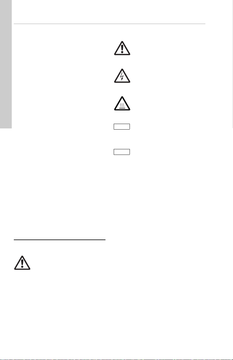
1. Symbols used in this document
Warning
If these safety instructions are not
observed, it may result in personal
2
3
4
4
4
4
4
4
5
5
6
6
7
8
9
injury.
Warning
If these instructions are not
observed, it may lead to electric
shock with consequent risk of
serious personal injury or death.
Warning
The surface of the product may be
so hot that it may cause burns or
personal injury.
Notes or instructions that
make the job easier and
ensure safe operation.
If these safety instructions are
not observed, it may result in
malfunction or damage to the
equipment.
Warning
Prior to installation, read these
installation and operating
instructions. Installation and
operation must comply with local
regulations and accepted codes of
good practice.
2
Page 3

2. Limited warranty
Products manufactured by GRUNDFOS PUMPS
CORPORATION (Grundfos) are warranted to
the original user only to be free of defects in
material and workmanship for a period of 36
months from date of manufacture. Grundfos'
liability under this warranty shall be limited to
repairing or replacing at Grundfos' option,
without charge, F.O.B. Grundfos' factory or
authorized service station, any product of
Grundfos' manufacture. Grundfos will not be
liable for any costs of removal, installation,
transportation, or any other charges which may
arise in connection with a warranty claim.
Products which are sold but not manufactured
by Grundfos are subject to the warranty
provided by the manufacturer of said products
and not by Grundfos' warranty. Grundfos will not
be liable for damage or wear to products caused
by abnormal operating conditions, accident,
abuse, misuse, unauthorized alteration or repair,
or if the product was not installed in accordance
with Grundfos' printed installation and operating
instructions.
To obtain service under this warranty, the
defective product must be returned to the
distributor or dealer of Grundfos' products from
which it was purchased together with proof of
purchase and installation date, failure date, and
supporting installation data. Unless otherwise
provided, the distributor or dealer will contact
Grundfos or an authorized service station for
instructions. Any defective product to be
returned to Grundfos or a service station must
be sent freight prepaid; documentation
supporting the warranty claim and/or a Return
Material Authorization must be included if so
instructed.
GRUNDFOS WILL NOT BE LIABLE FOR ANY
INCIDENTAL OR CONSEQUENTIAL
DAMAGES, LOSSES, OR EXPENSES ARISING
FROM INSTALLATION, USE, OR ANY OTHER
CAUSES. THERE ARE NO EXPRESS OR
IMPLIED WARRANTIES, INCLUDING
MERCHANTABILITY OR FITNESS FOR A
PARTICULAR PURPOSE, WHICH EXTEND
BEYOND THOSE WARRANTIES DESCRIBED
OR REFERRED TO ABOVE.
Some jurisdictions do not allow the exclusion or
limitation of incidental or consequential
damages and some jurisdictions do not allow
limit actions on how long implied warranties may
last. Therefore, the above limitations or
exclusions may not apply to you. This warranty
gives you specific legal rights and you may also
have other rights which vary from jurisdiction to
jurisdiction.
English (US)
3
Page 4

English (US)
3. Safety warning
4. Pre-installation checklist
3.1 Read this booklet
This booklet is designed to help a certified
installer to install, begin operation of, and
troubleshoot the Grundfos Small UP and UPS
pumps.
Following the instructions will ensure safe,
trouble-free operation.
This booklet should be left with the owner of the
pump for future reference and information
regarding its operation. Should the owner
experience any problems with the pump, a
certified professional should be contacted.
3.2 Electrical work
All electrical work should be performed by a
qualified electrician in accordance with the latest
edition of the National Electrical Code, local
codes and regulations.
Warning
A faulty motor or wiring can cause
electrical shock that could be fatal,
whether touched directly or
conducted through standing water.
For this reason, proper grounding
of the pump to the power supply's
grounding terminal is required for
safe installation and operation.
In all installations, the
above-ground metal plumbing
should be connected to the power
supply ground as described in the
National Electrical Code. All wiring
must comply with the National
Electrical Code, state, and local
regulations.
4.1 Confirm you have the correct pump
• Read the pump nameplate to ensure it is the
one you ordered.
• Compare the pump's nameplate data and its
performance curve (for head, gpm, etc.) with
the application in which you plan to install it.
• Will the pump do what you expect it to do?
4.1.1 Pump to system type recommendations
• Open systems (i.e. potable water): Stainless
steel or bronze volute (pump housing) only.
• Closed systems (i.e. airless, non-potable
water): Cast iron, stainless steel, or bronze
volute (pump housing).
Other considerations regarding Grundfos small
UP and UPS pumps:
• These pumps are intended for indoor use
only.
• If installed outdoors the pump must be
protected by an appropriate, well ventilated,
water-tight enclosure to keep out moisture
and dirt.
• Minimum ambient temperatures must be no
lower than 33 °F ( 1 ° C ).
• For ambient and fluid temperature see
sections 4.4 Pumped liquid requirements
and 9. Additional technical data.
4.2 Check the condition of the pump
The pump's shipping carton is specially
designed around the pump during production to
prevent damage.
As a precaution, it should remain in the carton
until you are ready to install it. At that point, look
at the pump and examine it for any damage that
may have occurred during shipping.
Examine any other parts of the shipment as well
for any visible damage. Once the pump has
been removed from the box, care should be
taken NOT to drop or mishandle the pump.
Box contents:
• one pump
• two gaskets (flanged units only)
• one Installation and Operation Instruction
(I&O).
4
Page 5

4.3 Verify electrical requirements
Note
Caution
Verify the electrical supply to be certain the
voltage, phase and frequency match that of the
pump motor. The proper operating voltage and
other electrical information can be found on the
pump nameplate.
This pump's motor is designed to run on ± 10 %
of the nameplate-rated voltage.
4.4 Pumped liquid requirements
Warning
The Grundfos Small UP/UPS pump
is intended for use with water only.
The pump must not be used for the
transfer of flammable liquids such
as diesel oil, gasoline, and similar
liquids.
The pump is not for pool or marine
use.
The pump can be used to circulate:
• Potable hot water.
• Water containing glycol for hydronic heating
(see section 9. Additional technical data for
additional limitations).
• Cooling water.
In domestic hot-water systems it is advisable to
use stainless steel pump housing versions of
this pump.
All pump types (stainless, bronze or cast iron
pump housing) should not be used in water with
a degree of hardness lower than 14 grains per
gallon of hardness.
Fluids should be clean and should not contain
solid particles, fibers, or mineral oils.
If the pump is installed in a heating system, the
water should meet the requirements of accepted
standards on water quality in heating systems.
The fluid should not contain solid particles,
fibers, or mineral oils.
The pump is lubricated and cooled by the liquid
being pumped. Therefore, the pumped liquid
must always be allowed to circulate through the
pump.
Extended periods without circulation will cause
premature wear to the bearings and excessive
motor heat.
The pumped liquid must meet the temperature
requirements listed in the following charts.
Fluid must never be allowed to
freeze during non-operational
periods.
Open systems
(domestic, potable hot water)
Fluid Ambient
Min. 36 °F (2 °C) 33 °F (1 °C)
Max. < 149 °F (65 °C) 100 °F (38 °C)
In domestic hot-water systems, it is
recommended to keep the liquid
temperature below 149 °F (65 °C) to
eliminate the risk of lime
precipitation.
(non-potable heating or cooling airless
Min. All
Max.
Max. 50 % glycol at 15 °F (-9.5 °C) liquid
(Hydraulic performance change can be
expected.)
Closed systems
fluid)
Pump
models
UPS 26-150
UPS 43-100
UPS 50-60
Water and glycol mix
Liquid Ambient
36 °F
(2 °C)
230 °F
(110 °C)
230 °F
(110 °C)
212 °F
(100 °C)
33 °F
(1 °C)
100 °F
(38 °C)
100 °F
(38 °C)
100 °F
(38 °C)
English (US)
5
Page 6
English (US)
5. Installation procedures
Warning
Never make any connections in the
pump terminal box unless the
electrical supply has been
switched off.
The pump should not be connected
to the electrical system until it has
been properly installed in the
piping system.
Warning
Risk of electrical shock - this pump
has not been investigated for use
in swimming pool or marine areas.
5.1 Piping considerations
When making piping connections, be sure to
follow the piping manufacturer's
recommendations and all code requirements for
piping material.
Thoroughly clean and flush all dirt and sediment
from the system before attempting to install the
pump.
5.1.1 Location in the piping line
The pump should never be located at the lowest
point of the piping system (where dirt and
sediment collect), nor should it be located at the
highest point of the piping system (where air
accumulates).
Warning
The pump must be positioned so
that someone cannot accidentally
come into contact with the hot
surfaces of the pump.
When installing the pump into the piping system,
Grundfos recommends that pressure gauges be
installed in the inlet and discharge flanges or
pipes. This will allow the pump and system
performance to be checked.
Do not block the pipe plugs in the pump housing
flanges by locating the terminal box over these
plugs.
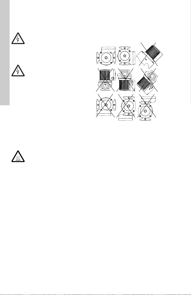
5.1.2 Mounting positions
The arrows on the pump housing indicate the
direction of water flow. The pump may be
installed in vertical or horizontal piping, but the
motor shaft must always remain horizontal,
as shown in fig. 1.
Fig. 1 Installation positions
5.1.3 Terminal box positions
At the bottom of the stator, closest to the pump
housing, there are three drain holes to allow
condensed water to escape. The drain holes
shall not be blocked for any reason and one
drain hole must always point downward.
There is not a drain hole directly below the
terminal box; therefore the terminal box must be
positioned in one of the positions shown in fig. 1
or fig. 2.
TM04 5646 3609
6
Page 7

Caution
Terminal box
position A
Terminal box
position B
Terminal box
position C
5.2 Changing the terminal box position
Warning
Before starting any work on this
circulator, be sure electrical supply
has been switched off and it cannot
be accidentally switched on.
If the pump is already installed in the system,
the system must be drained or the isolation
valves on both sides of the pump must be closed
and the pressure released/relieved by removing
the vent plug.
Warning
Exercise caution when draining the
system or removing the vent plug
as the fluid in the system may be
scalding hot and under pressure.
Only after the pressure has been relieved and
the pump drained should you proceed with the
next steps.
5.2.1 Rotating the terminal box
To change the position of the terminal box,
follow these steps:
1. Remove the four (5 mm) allen-head screws
holding the pump head onto the pump
housing.
2. Carefully lift/slide the pump head out and
away from the pump housing. Next rotate the
pump head and locate the terminal box in the
desired position. The terminal box can be
rotated in steps of 90 °. Review fig. 1 and
fig. 2 for possible/permissible positions.
DO NOT locate the terminal box beneath the
pump.
Use caution as the rotor assembly
can fall out of the pump head or
pump housing if the pump head is
pulled too far away from the pump
housing.
3. Make sure the O-ring is properly seated in
the pump housing.
4. Replace the pump head onto the pump
housing.
5. Diagonally tighten the 5 mm allen-head
screws evenly.
Torque to: 7 ft lbs. / 9.5 Nm.
6. Check to ensure the rotor turns freely. Do
this by removing the vent plug in the middle
of the pump nameplate. Insert a
medium-size, flat-blade screwdriver into the
slot at the exposed end of the shaft. Gently
turn the shaft. If it does not turn easily,
repeat steps 1 through 5 above. If the rotor
spins freely, proceed to step 7. Do not put
the vent plug back into the pump until the
end of step 9.
7. The position of the nameplate can be
changed by easing the outer edge of the
plate at the cutout with a screwdriver. Turn
the nameplate to the required position and
push into place.
8. Follow electrical instructions in section
5.3 Electrical connection.
9. Refill the system, open the isolation valves
and vent the system. Also allow air to vent
out of the pump; once water flows out the
vent hole, replace the vent plug removed in
step 6. See additional instructions in section
6.1 Vent the piping system.
10.Figure 2 shows acceptable terminal box
positions along with recommended drip
loops (dashed lines) in the electrical wiring
harness based on entry point.
Fig. 2 Acceptable terminal box positions
English (US)
TM04 5636 3609
7
Page 8

English (US)
Black
White
Green
Speed
switch
Capacitor
Black
White
Green
Capacitor
5.3 Electrical connection
Warning
Risk of electrical shock! The
electrical connection and
protection should be carried out in
accordance with the latest edition
of the National Electrical Code,
local codes and regulations by a
qualified electrician.
The safe operation of this pump
requires that it be grounded in
accordance with the National
Electrical Code and any state, local
governing codes and regulations.
Ground wires should be copper
conductors of at least the size of
the circuit conductor supplying
power to the pump. Connect the
ground wire to the grounding point
in the terminal box and then to an
acceptable ground. Do not ground
to gas or water supply line.
All wire sizes should be copper and
size-based on the ampacity
(current carrying properties of a
conductor) as required by the
National Electrical Code or local
regulations. Additionally UL
requires the following wire sizes to
be used: 18-12 Solid or 14-12
Stranded.
Both the power and grounding
wires must be suitable for at least
194 °F (90 °C).
Proper operating voltage and other electrical
information can be found on the pump
nameplate attached to the top of the motor.
• The motor is thermally protected on all three
speeds and no additional external protection
is needed.
• See fig. 3 for proper grounding and supply
power connection locations (115 V and
208-230 V).
• The terminal connections are toggle/lever
push design. Push the lever down and insert
the field wiring. Push the lever down and pull
to remove wires.
• Next, use care when installing the terminal
box cover with speed switch. Insert the
Phillips head screw through the cover and
tighten to a snug fit.
• An external "Drip Loop" is recommended in
the electrical wiring harness; see fig. 2.
• Where an external "Drip Loop" is not
possible, or if the wiring enters through the
upward facing (top) surface of the box, then
an internal "Drip Loop" is recommended; see
fig. 3.
Fig. 3 Examples of ground and power
supply connections (115 V and
108-230 V) with internal drip loop
TM04 5634 3609
8
Page 9

5.4 Insulating shells (if equipped)
Insert flange bolts
toward pump
Insert flange bolts
toward pump
Do not block weep slots
Do not block weep slots
For pumps with provided insulation shell, the
following procedures are required to insure safe
and proper installation.
1. Pump and mating piping flange bolts need to
be installed towards the pump as illustrated
in fig. 4.
2. Apply water proof, heat resistant, silicon
based sealant to insulation shell. Care
should be taken to not block weep slots for
pump motor when applying sealant. Failure
to follow proper sealant location procedures
could damage motor and insulation shell.
See fig. 5 for proper locations when applying
sealant.
3. Mate the two insulation shells over the pump
volute as illustrated in fig. 6. If the shells do
not mate; flange bolts are installed in the
wrong direction, review step one and or
switch mating shell location.
4. Proper amount of time should be allowed for
sealant to set-up before any additional
installation work is performed. See sealant
manufactures recommended time for sealant
set-up. See fig. 7 for final configuration.
English (US)
TM05 1889 3811TM05 1890 2515TM05 1891 2515
Fig. 5 Applying silicon sealant (dotted
areas indicate sealant)
Fig. 4 Connect pump to piping, installing
Fig. 6 Insulating shell installation (dotted
areas indicate sealant)
TM05 1888 2515
flange bolts toward the pump
Fig. 7 Ready for insulation wrap
9
Page 10

English (US)
Caution
Inspection screw/
Low
HHH
Medium
High
QQ Q
H = Head and Q = Flow
6. Starting the pump
6.1 Vent the piping system
After the pump has been installed and the
electrical connections made, the piping system
must be vented.
Never operate the pump dry - the
system must first be filled with
liquid and vented.
NOTE: Do not vent the piping system through
the pump. Instead, follow these steps:
1. Fill and pressurize the system with liquid,
and vent all trapped air from the piping by
suitable means.
2. If any isolation valves are used, make sure
they are OPEN.
Warning
If the vent screw/plug is to be
loosened, care should be taken to
ensure that the escaping scalding
hot liquid does not cause personal
injury or damage to components.
3. Vent the pump by removing the vent plug.
When water exists through the port, the
pump is fully vented / primed.
4. Reinstall the vent plug.
6.2 Speed selection
UPS models
Speeds can be changed via the speed switch on
the terminal box cover. Power must be turned off
before changing speeds. The speed in the three
positions appears in the following table; also see
fig. 10.
UP models
Speed is fixed on Speed 3 (High) and cover
does not have a switch (cover is solid).
Fig. 9 Terminal box cover with speed
Switch position
Low (Speed 1) approx. 60 %
Medium (Speed 2) approx. 80 %
High (Speed 3) 100 %
Changing to lower speeds offers considerable
reduction in energy consumption and less noise
in the system.
switch in medium speed (Speed 2)
Speed in % of max.
speed
TM04 5641 2515
Fig. 8 Vent screw/plug removal for pump
10
venting
TM04 5644 3609
Fig. 10 Pump performance at speed
settings
TM04 5640 3609
Page 11

7. Fault finding
7.1 Fault finding chart
Warning
Before removing the terminal box cover, make sure that the electrical supply has
been switched off and that it cannot be accidentally switched on.
Warning
The pumped liquid may be scalding hot and under high pressure. Before any
removal or dismantling of the pump, the system must be drained or the isolation
valves on both sides of the pump must be closed.
Fault Cause Remedy
1. The pump does not
run.
2. The pump does not
run.
3. Noise in the system. a) Air in the system. Vent the system.
4. Noise in the pump. a) Air in the pump. Vent the pump.
5. Insufficient heat in
some places in the
heating system.
a) External circuit breaker is
switched off.
b) Current-/voltage-operated
ground fault circuit
interrupter has tripped.
a) Rotor is blocked. Switch off the electrical supply and
b) The speed switch is not
fully positioned (is
between speeds)
c) The pump has been cut
out by the thermal
overload switch due to
high liquid temperature.
b) The pump flow is too
high.
c) The pressure is too high. Reduce the pump performance.
b) The inlet pressure is too
low.
a) The pump performance
is too low.
b) The performance is too
high.
Switch the circuit breaker on.
Repair the insulation defects and reset
the interrupter.
clean/repair the pump.
Switch off the electrical supply at the
external circuit breaker and change
speed switch into position.
Check that the liquid temperature falls
within the specified range. The pump will
restart automatically when it has cooled
to normal temperature.
Reduce the pump performance.
Increase the inlet pressure and/or check
the air volume in the expansion tank (if
installed).
Increase the pump performance, if
possible. Flow too fast through the
boiler/heat exchanger may not allow for
the proper BTU transfer to the fluid. If
fluid is too slow, fluid may be cooling too
much before returning from the system.
If changing speeds does not resolve the
problem, replacing the pump with a
properly sized pump may be required.
English (US)
11
Page 12

English (US)
7.2 Preliminary checks
Supply voltage
To check the voltage being supplied to the
motor, use a voltmeter.
Warning
Be careful, since power is still
being supplied to the pump. Do not
touch the voltmeter leads together
while they are in contact with the
power lines.
Single-phase motors
Touch one voltmeter lead to each of the lines
supplying power to the pump as shown in fig. 11:
• L and N for 115 V and 208-230 V circuits
These tests should give a reading of full line
voltage.
Evaluation
When the motor is under load, the voltage
should be within 10 % (+ or -) of the nameplate
voltage.
Any variation larger than this may indicate a
poor electrical supply and can cause damage to
the motor windings. The motor should not be
operated under these conditions. Contact your
power supplier to correct the problem or change
the motor to one requiring the voltage you are
receiving.
and N = L2 for 208-230 V circuits in
(L = L
1
the US)
Fig. 11 Testing with voltmeter
7.3 Current measur emen t
To check the current using an ammeter, follow
these steps:
1. Make sure the pump is operating.
2. Set the ammeter to the proper scale.
3. Place the tongs of the ammeter around the
leg to be measured.
4. Compare the results with the amp draw
information on the motor nameplate.
5. Repeat for the other legs.
Fig. 12 Current measurement
Evaluation
If the current draw exceeds the listed nameplate
amps, or if the current imbalance is greater than
5 % between each leg, then check the following:
• The voltage supplied to the pump may be too
high or too low.
• The terminals/wires in the terminal box or to
circuit breaker may be loose.
• The contacts on the motor starter may be
burned.
TM04 5645 3609
• The terminals in the starter or terminal box
may be loose.
• There may be a winding defect. Check the
winding and insulation resistance; see
section 7.6 Resistance tables.
• The motor windings may be shorted or
grounded.
• The pump may be damaged in some way
and may be causing a motor overload.
• A voltage supply problem may exist.
TM04 5639 3609
12
Page 13

7.4 Insulation resistance
L
N
(lead-to-ground)
To check the insulation resistance
(lead-to-ground) of the motor and leads, use a
megohmmeter and follow these steps:
1. Turn the POWER OFF.
2. Disconnect all electrical leads to the motor.
3. Set the scale selector on the megohmmeter
to R x 100K, touch its leads together, and
adjust the indicator to zero.
4. Touch the leads of the megohmmeter
individually to each of the motor leads and to
ground (i.e. L to ground; N to ground, etc.).
7.6 Resistance tables
Checking connections in the terminal box at the
power connections L and N; see fig. 14 for 1 15 V
and 208-230 V.
Connection
115 V
L to N
(Speed 3)
L to N
(Speed 2)
L to N
(Speed 1)
Ohm value
range
= 6.9 - 8.01 7.55
= 9.7 - 11.38 10.54
= 12.97 - 15.23 14.10
Nominal
English (US)
Fig. 13 Insulation resistance measurement
Evaluation
The resistance values for new motors must
exceed 1,000,000 ohms. If they do not, replace
power head.
7.5 Winding resistance (line-to-line)
To check the winding resistance of the motor
windings, use a megohmmeter and follow these
steps.
1. Turn the POWER OFF.
2. Disconnect all electrical leads to the motor.
3. Set the scale selector on the megohmmeter
to R x 1, touch its leads together and adjust
the indicator to zero.
4. Using the charts in section 7.6 Resistance
tables for reference, touch the leads of the
megohmmeter to the appropriate pair of
connectors. Check all pairs that are present
and write down and label (RA1, RS1, RS2)
all readings.
– In T-box at L & N: UP will = Speed 3/High
– In T-box at L & N: UPS value depends on
the selected speed (Speed 1, 2, or 3)
– For both UP and UPS: with the terminal
box removed, check all combinations RA,
S1, S2.
5. Compare your readings to the matching
model, phase and voltage listed in the charts
in section 7.6 Resistance tables.
Evaluation
The resistance values must fall within the
tolerances listed in section 7.6 Resistance
tables. If they do not, replace the power head.
Connection
L to N
(Speed 3)
208 V
230 V
TM04 5638 3609
* T can only be checked with the terminal box
removed; if the thermiks is open the pump will
not run.
Fig. 14 Power connections L and N
-
L to N
(Speed 2)
L to N
(Speed 1)
Ohm value
range
= 34.63 - 40.66 37.65
= 41.57 - 48.81 45.19
= 56.67 - 66.53 61.60
Nominal
TM04 5633 3609
13
Page 14

English (US)
Checking at the pin connection behind the
terminal box (see section 8.3 Replacing the
terminal box or capacitor for terminal box
removal):
Stator pin
connection
Winding groups
1 to 2 RA: Main winding
4 to 5 RS
6 to 7 RS
: Auxiliary winding
1
: Auxiliary winding
2
2 to 8 T: Thermiks
Connection
Ohm value
range
RA (1 to 2) = 6.7 - 7.9 7.3
RS
(4 to 5) = 3.0 - 3.6 3.3
115 V
1
RS
(6 to 7) = 3.0 - 3.6 3.3
2
T (2 to 8) = 0
Connection
Ohm value
range
RA (1 to 2) = 30.4 - 35.6 33
208 V
RS
(4 to 5) = 12.0 - 14.0 13
1
-
RS
(6 to 7) = 12.0 - 14.0 13
230 V
2
T (2 to 8) = 0
Figure 15 shows terminal plug-in stator
relationship to the top / nameplate end of the
stator.
Nominal
Nominal
8. Replacing components
Warning
Before starting any work on this
circulator, make sure electrical
supply has been switched off and
that it cannot be accidentally
switched on.
8.1 Removing the pump head
1. Disconnect or TURN OFF the power supply.
2. Close any isolating valves on either side of
the pump to avoid draining the system of
liquid.
3. Remove the vent plug to relieve any system
pressure retained in the pump. Exercise
caution as the fluid may be scalding hot
and under pressure. Only after the
pressure has been relieved and the pump
drained should you proceed with the next
steps.
4. Disconnect the electrical leads from the
terminal box.
5. Disconnect and remove the conduit from the
terminal box.
6. Loosen and remove the four 5 mm
allen-head screws which connect the pump
head housing to the pump housing.
7. Remove the pump head from the pump
housing. Exercise care as the rotor may
fall out of the stator or pump housing.
8. Clean the machined surfaces in the pump
housing of any foreign material.
Fig. 15 Stator socket
Fig. 16 Internal wiring
14
TM04 5643 3609TM04 5637 3609
Page 15

8.2 Fitting the pump head
Terminal box
Stator housing Rotor assembly
ImpellerBearing plate
O-ring
Pump housing
Thrust bearing
Allen
screws (4)
5 mm
1. Carefully remove the new pump head
assembly from its packaging. Separate the
impeller/rotor assembly from the new pump
head.
2. While holding the thrust bearing plate,
carefully place the impeller/rotor assembly
into the pump housing. The bearing plate
should fit snugly into the lowest machined
surface in the pump housing.
3. Ensure that the impeller/rotor assembly can
rotate freely.
4. Place the O-ring over the rotor and locate it
into the inner diameter of the pump housing.
5. Carefully place the pump head housing over
the rotor and rotate it so the terminal box is
in the position you wish; see section
5.2.1 Rotating the terminal box.
6. Ensure that the pump head housing is
properly seated on the pump housing. Do
not force the two together - if there is
binding, disassemble them and repeat steps
2 to 6. Cross-tighten the allen-head screws
evenly.
Torque to: 7 ft lb / 9.5 Nm.
7. Check to make sure the rotor turns freely. Do
this by removing the vent plug in the middle
of the pump nameplate. Insert a
medium-size, flat-blade screwdriver into the
slot at the exposed end of the shaft. Gently
turn the shaft. If it does not turn easily,
repeat steps 1 through 6 above. If the rotor
spins freely, proceed to step 8. Do not put
the vent plug back into the pump until the
end of step 10.
8. The position of the nameplate can be
changed by easing the outer edge of the
plate at the cutout with a screwdriver. Turn
the nameplate to the required position and
push into place.
9. Follow electrical instructions in section
5.3 Electrical connection.
10.Refill the system, open the iso lation valves
and vent the system. Also allow air to vent
out of the pump, once water flows out the
vent hole, replace the vent plug removed in
step 7. See additional instructions in section
6.1 Vent the piping system.
English (US)
Fig. 17 Removing and fitting the pump head
TM04 5635 3609
15
Page 16

English (US)
Terminal box
holding screws
8.3 Replacing the terminal box or capacitor
Warning
Before starting any work on this
circulator, make sure electrical
supply has been switched off and
that it cannot be accidentally
switched on.
Removal
1. Before replacing the terminal box and
capacitor, make sure the power is OFF.
2. Remove the terminal box cover/lid by
completely loosening the Phillips head screw
in the center of the cover/lid.
3. Disconnect all wiring. Move the capacitor to
allow access to the screws.
4. Remove the two T15 Torx head screws
holding the terminal box in place.
5. Pull firmly and evenly on both sides of the
terminal box to free it from the stator / pump
head.
Installation
1. Carefully press the terminal box into the
stator socket.
2. Replace the two T15 Torx head screws and
torque to 1.5 ft.-lbs / 2 Nm.
3. Replace the wiring (refer to section
5.3 Electrical connection).
4. Use care when installing the terminal box
cover with speed switch. Next insert the
Phillips head screw through the cover and
tighten to a snug fit.
5. Restore power.
TM04 5641 2515TM04 5642 3609
Fig. 18 Terminal box lid / cover
Fig. 19 Terminal box holding screws
16
Page 17

9. Additional technical data 10. Disposal
Caution
Supply voltage:
Motor protection: Thermally protected
Enclosure class: CSA Type 2
Insulation class: H
Max. discharge
pressure:
Max. sound
pressure level:
Water hardness: 14 dH
(domestic, potable hot water)
Fluid A mbient
Min. 36 °F (2 °C) 33 °F (1 °C)
Max. < 149 °F (65 °C) 100 °F (38 °C)
1 x 115 V ± 10 %, 60 Hz
1 x 208-230 V ± 10 %, 60 Hz
145 psi (10 bar)
30 dB(A)
Open systems
In domestic hot-water systems, it is
recommended to keep the liquid
temperature below 149 °F (65 °C) to
eliminate the risk of lime
precipitation.
This product or parts of it must be disposed of in
an environmentally sound way:
1. Use the public or private waste collection
service.
2. If this is not possible, contact the nearest
Grundfos company or service workshop.
English (US)
Subject to alterations.
(non-potable heating or cooling airless
Min. All
Max.
Max. 50 % glycol at 15 °F (-9.5 °C) liquid
(Hydraulic performance change can be
expected.)
Closed systems
fluid)
Pump
models
UPS 26-150
UPS 43-100
UPS 50-60
Water and glycol mix
Fluid Ambient
36 °F
(2 °C)
230 °F
(110 °C)
230 °F
(110 °C)
212 °F
(100 °C)
33 °F
(1 °C)
100 °F
(38 °C)
100 °F
(38 °C)
100 °F
(38 °C)
17
Page 18

18
Page 19

GRUNDFOS Kansas City
17100 West 118th Terrace
Olathe, Kansas 66061
Phone: (913) 227-3400
Fax: (913) 227-3500
www.grundfos.us
GRUNDFOS Canada
2941 Brighton Road
Oakville, Ontario L6H 6C9 Canada
Phone: +1-905 829 9533
Telefax: +1-905 829 9512
www.grundfos.ca
GRUNDFOS México
Boulevard TLC No. 15
Parque Industrial Stiva Aeropuerto
C.P. 66600 Apodaca, N.L. México
Phone: 011-52-81-8144 4000
Fax: 011-52-81-8144 4010
www.grundfos.mx
Grundfos companies
Page 20

L-UP-TL-062
98419789 0715
ECM: 1161312
www.grundfos.com
© Copyright Grundfos Holding A/S
owned by Grundfos Holding A/S or Grundfos A/S, Denmark. All rights reserved worldwide.
The name Grundfos, the Grundfos logo, and be think innovate are registered trademarks
 Loading...