

Grundfos UPE 2000 Series, UPED 50-120, UPED 100-60, UPED 65-120, UPED 80-120 Installation And Operating Instructions Manual
Page 1

GRUNDFOS INSTRUCTIONS
UPE Series 2000
UPED 50-120, UPED 65-120, UPED 80-120, UPED 100-60
Installation and operating instructions
Page 2

Декларация о соответствии
Мы, фирма Grundfos, со всей от ветственно стью заявляем, что
изделия UPE серии 2000 к которым и отно сится данное
свид етельст во, отвечают требованиям следующих указаний Совета
ЕС об унификации законодательных предписаний стран-членов ЕС:
– Машиностроение (98/37/ЕС).
– Электрические машины для эксплуатации в пределах
определенного диапазона значений напряжения
(2006/95/ЕС).
Применявшиеся стандарты: Евростандарт EN 60335-1: 2002 и
EN 60335-2-51: 2003.
– Электромагнитная
Применявшиеся стандарты: Евростандарт EN 61800-3.
совместимость (89/336/ЕЭС).
Izjava o usklađenosti
Mi, Grundfos, izjavljujemo uz punu odgovornost, da su proizvodi
UPE serija 2000 na koje se ova izjava odnosi, sukladni smjernicama
Savjeta za prilagodbu propisa država-članica EZ:
– Strojevi (98/37/EZ).
–Električni pogonski uređaji za korištenje unutar određenih granica
napona (2006/95/EZ).
Korištene norme: EN 60335-1: 2002 i EN 60335-2-51: 2003.
– Elektromagnetska kompatibilnost (89/336/EEZ).
Korištena norma: EN 61800-3.
Prohlášení o shodě
My firma Grundfos prohlašujeme na svou plnou odpovědnost, že
výrobky UPE série 2000 na něž se toto prohlášení vztahuje, jsou v
souladu s ustanoveními směrnice Rady pro sblížení právních předpisů
členských států Evropského společenství v oblastech:
– strojírenství (98/37/EG).
– provozování spotřebičů v toleranci napětí (2006/95/EG),
použité normy: EN 60335-1: 2002 a EN 60335-2-51: 2003.
– elektromagnetická kompatibilita (89/336/EWG),
použitá norma: EN 61800-3.
Konformitätserklärung
Wir Grundfos erklären in alleiniger Verantwortung, dass die Produkte
UPE Serie 2000 auf die sich diese Erklärung bezieht, mit den folgenden
Richtlinien des Rates zur Angleichung der Rechtsvorschriften der EGMitgliedstaaten übereinstimmen
– Maschinen (98/37/EG).
– Elektrische Betriebsmittel zur Verwendung innerhalb bestimmter
Spannungsgrenzen (2006/95/EG).
Normen, die verwendet wurden: EN 60335-1: 2002 und
EN 60335-2-51: 2003.
– Elektromagnetische Verträglichkeit (89/336/EWG).
Norm, die verwendet wurde: EN 61800-3.
Izjava o ustreznosti
Mi, Grundfos, pod polno odgovornostjo izjavljamo, da so izdelki
UPE serija 2000 na katere se ta izjava nanaša, v skladu z naslednjimi
smernicami Sveta za uskladitev pravnih predpisov držav članic
Evropske skupnosti:
– Stroji (98/37/EG).
–Električna pogonska sredstva za uporabo v določenih napetostnih
mejah (2006/95/EG).
Uporabljeni normi: EN 60335-1: 2002 in EN 60335-2-51: 2003.
– Elektromagnetna kompatibilnost (89/336/EWG).
Uporabljena norma: EN 61800-3.
Izjava o konformitetu
Mi, Grundfos, izjavljujemo pod potpunom odgovornošću da su
proizvodi UPE serije 2000 na koje se odnosi ova izjava u saglasnosti sa
smernicama i uputstvima Saveta za usaglašavanje pravnih propisa
članica Evropske unije:
– mašine (98/37/EG).
–električna oprema razvijena za korišćenje unutar određenih
naponskih granica (2006/95/EG),
korišćeni standardi: EN 60335-1: 2002 i EN 60335-2-51: 2003.
– elektromagnetna usaglašenost (89/336/EWG),
korišćen standard: EN 61800-3.
Declaration of Conformity
We Grundfos declare under our sole responsibility that the products
UPE Series 2000 to which this declaration relates, are in conformity with
the Council Directives on the approximation of the laws of the EC Member States relating to
– Machinery (98/37/EC).
– Electrical equipment designed for use within certain voltage limits
(2006/95/EC).
Standards used: EN 60335-1: 2002 and EN 60335-2-51: 2003.
– Electromagnetic compatibility (89/336/EEC).
Standard used: EN 61800-3.
Bjerringbro, 15th March 2007
Svend Aage Kaae
Technical Director
2
Page 3

UPE Series 2000
UPED 50-120, UPED 65-120, UPED 80-120, UPED 100-60
Руководство по монтажу и эксплуатации 4
Navodila za montažo in obratovanje 32
Montažne i pogonske upute 55
Uputstvo za montažu i upotrebu 78
Montážní a provozní návod 102
Installation and operating instructions 126
Montage- und Betriebsanleitung 147
3
Page 4

CONTENTS
1. General description 126
1.1 Master pump and slave pump 126
2. Applications 127
2.1 Pumped liquids 127
3. Installation 127
3.1 Terminal box positions 127
3.2 Changing the terminal box position 127
3.3 Changing the nameplate position 128
3.4 Non-return valve 128
3.5 Insulation 128
3.6 Frost protection 128
4. Electrical connection 128
4.1 Supply voltage 128
4.2 Wiring diagram 129
5. Start-up 130
6. Functions 130
6.1 Control of twin-head pumps 130
6.2 Control modes 130
6.3 Selection of control mode 131
6.4 Max. or min. curve duty 132
6.5 Constant curve duty 132
6.6 Temperature influence 133
6.7 Indicator lights 133
6.8 External fault indications 134
6.9 External analog 0-10 V controller 134
6.10 External forced control 135
6.11 Deactivating the control panel 135
6.12 Bus communication 135
6.13 Wireless remote control 135
7. Setting the pump 136
7.1 Factory settings 136
7.2 Control panel 136
7.3 R100 139
7.4 Menu OPERATION 140
7.5 Menu STATUS 140
7.6 Menu INSTALLATION 141
7.7 Priority of settings 143
8. Fault finding chart 143
9. Megging 145
9.1 High-voltage test 145
10. Technical data 145
11. Disposal 146
Page
The desired head can be set on the pump control
panel.
These instructions apply to the pump types
UPED 50-120, UPED 65-120, UPED 80-120 and
UPED 100-60.
The pump offers the following functions:
• Control of twin-head pump:
- Alternating operation,
- Standby operation,
- Synchronous operation,
- Single-pump operation.
• Proportional-pressure control (factory setting).
The head is changed in accordance with the flow
demand. The desired head can be set on the
pump control panel.
• Constant-pressure control. A constant head is
maintained, irrespective of flow demand. The
desired head can be set on the pump control
panel.
• Constant curve duty. The pump runs at a con-
stant speed on or between the max. and min.
curves.
• Temperature influence. The head varies depend-
ing on the liquid temperature.
• External fault signal via a potential-free output.
• External analog control of head or speed from
an external 0-10 V signal transmitter.
• External forced control via inputs for:
- Start/stop,
- Max. curve,
- Min. curve (night-time duty).
• Bus communication. As the UPE Series 2000
incorporates an input for bus communication, the
pump can be controlled and monitored by a
GRUNDFOS Pump Management System 2000 or
a building management system.
• Remote control. The pump can be operated by
means of the Grundfos wireless remote control
R100.
1.1 Master pump and slave pump
Slave pump
Master pump
Prior to installation, read these installation
and operating instructions. Installation and
operation must comply with local regulations and accepted codes of good practice.
1. General description
The UPE Series 2000 is a complete range of circulator pumps with integrated differential pressure control enabling adjustment of pump performance to the
actual system requirements. In many systems, this
will mean a considerable reduction in power consumption, prevent noise from thermostatic valves
and similar fittings, and improve the control of the
system.
126
TM02 1389 1101
Fig. 1
Page 5

2. Applications
The UPE Series 2000 is designed for circulating liquids in heating systems. The pumps can also be
used in domestic hot-water systems.
UPE Series 2000 is suitable for:
• systems with a constant flow where it is desira-
ble to optimize the setting of the pump duty point
and
• systems with variable flow-pipe temperatures.
2.1 Pumped liquids
Thin, clean, non-aggressive and non-explosive liquids, not containing solid particles, fibres or mineral
oil.
In heating systems, the water should meet the
requirements of accepted standards on water quality
in heating systems, e.g. the German standard VDI
2035.
In domestic hot-water systems, it is advisable to
use UPED pumps only for water with a degree of
hardness lower than approx. 14°dH.
For water with a higher degree of hardness a directcoupled TPE pump is recommended.
The pump must not be used for the transfer of inflammable liquids such as diesel
oil, petrol or similar liquids.
Liquid flow
direction
→
3. Installation
When installing pumps, types UPED 50-xx and
65-xx, with oval bolt holes in the pump flange,
washers must be used as shown in fig. 2.
Installation
Washer
Fig. 2
See mounting dimensions at the end of these
instructions.
Care should be taken to ensure that persons cannot accidentally come into contact with hot surfaces of the pump.
The pump must be installed with the motor shaft horizontal.
Arrows on the pump housing indicate the liquid flow
direction through the pump.
The permissible liquid flow directions through the
pump are indicated by an "X" in the following table:
Pump
TM01 0683 1997
Pump type
UPED 50-120 X X X
UPED 65-120 X X X
UPED 80-120 X X X
UPED 100-60 X X X
Note: Pumps mounted in horizontal pipes must be
fitted with an automatic air vent in the upper part of
the pump housing.
The automatic air vent is not supplied with the pump.
3.1 Terminal box positions
The terminal box can be turned to the positions
shown in figure 3.
Note: The terminal box must only be turned to the
positions below.
Fig. 3
TM02 1389 1101
TM02 1391 1101
3.2 Changing the terminal box position
Before any dismantling of the pump, the
system must be drained or the isolating
valves on either side of the pump must be
closed as the pumped liquid may be scalding hot and under high pressure.
Change the terminal box position as follows:
1. Remove the four screws holding the pump head.
2. Turn the pump head to the required position.
3. Replace the four screws and tighten securely.
TM02 2104 3401
TM02 1392 1101
TM02 1393 1101
127
Page 6

3.3 Changing the nameplate position
When the terminal box position has been changed,
the pump nameplate must be turned so that the cutout points downwards. This allows water from a possible venting to escape.
To change the nameplate position, ease the outer
edge of the nameplate at the cutout with a screwdriver, turn the nameplate to the new position and
push it into place.
3.4 Non-return valve
If a non-return valve is fitted in the pipe system, see
fig. 4, it must be ensured that the minimum discharge
pressure is always higher than the closing pressure
of the valve. This is especially important in proportional-pressure control mode (reduced head at low
flows).
Fig. 4
3.5 Insulation
If the pump is insulated, it must be ensured that the
differential pressure and temperature sensor in the
pump housing is not covered.
3.6 Frost protection
If the pump is not being used during periods of frost,
the necessary steps must be taken to prevent frost
bursts.
4. Electrical connection
The electrical connection and protection should be
carried out in accordance with local regulations.
Never make any connections in the pump
terminal box unless the electricity supply
has been switched off for at least
5 minutes.
The earth terminal of the pump must be
earthed.
The pump must be connected to an external mains switch with a minimum contact
gap of 3 mm in all poles.
Earthing or neutralization can be used for
protection against indirect contact.
Megging must be carried out as described
in section 9. Megging.
If the pump is connected to an
electric installation where an
earth leakage circuit breaker
(ELCB) is used as an additional
protection, this circuit breaker
must trip out when earth fault
currents with DC content (pul-
TM02 0640 0301
• The pump requires no external motor protection.
• If a classification of the pump to overvoltage prop-
• The operating voltage and frequency are marked
4.1 Supply voltage
3 x 400-415 V ±10%, 50 Hz.
sating DC) and smooth DC
earth fault currents occur.
The earth leakage circuit
breaker must be marked with
the two symbols shown.
erty class 1 or 2 in accordance with
VDE 0160/12.90 is required, a prefilter must be
installed. Contact Grundfos for further information.
on the pump nameplate. Please make sure that
the motor is suitable for the electricity supply on
which it will be used.
128
Page 7

4.2 Wiring diagram
L1L3
321
10987654
L2
1211
Signal output
213
NCNO
C
Differential pres-
sure and temper-
ature sensor
Bus signal
used for
master/slave
communication
AYB
546 987101112
White
Screen
Brown
Fig. 5
Note:
• A possible external controller is to be connected
to the master pump (terminals 7 to 12).
• If the pump is to be connected to a PMU 2000 or
PCU 2000, it must be set to single-pump operation, see supplement to these instructions.
• If no external on/off switch is connected, the connection across terminals 7 and 8 should be maintained.
• If the 0-10 V input is used (terminals 11 and 12),
there must be a connection across terminals
7 and 9 (the input for the min. curve must be
closed).
• All cables used must be heat-resistant up to at
least +85°C.
• All cables used must be installed in accordance
with EN 60204-1.
Mains connection
L2
L3
L1
Start/stop
Min. curve
(night-time duty)
Max. curve
Analog 0-10 V
input
DC 0-10 V
Stop Min. Max.
• Wires connected to
- outputs 1 to 3,
- inputs 4 to 12,
- supply terminals and
- differential pressure and temperature
sensor
must be separated from each other and
from the supply by reinforced insulation.
• All leads connected to a terminal block
must be tied up at the terminals.
Concerning demands on signal wires and signal
transmitters, see section 10. Technical data.
A connection example can be found on page 172.
TM01 1105 3399
129
Page 8

5. Start-up
Do not start the pump until the system has been filled
with liquid and vented. Furthermore, the required
minimum inlet pressure must be available at the
pump inlet, see section 10. Technical data.
The system cannot be vented through the pump.
As the pump is self-venting, it need not be vented
before start-up.
If the inspection screw is to be slackened,
see fig. 6, care should be taken to ensure
that the escaping, scalding hot liquid does
not cause personal injury or damage to
components.
Inspection screw
Fig. 6
The pump may be noisy, when first switched on, due
to air remaining in the chamber. This noise should
cease after a few minutes running.
After start-up, the desired operating mode and possibly pump head are set.
6. Functions
Some functions can only be selected by means of
the remote control R100. Where and how the different settings are made will appear from section
7. Setting the pump.
6.1 Control of twin-head pumps
Factory setting can be changed by means of the
R100.
Twin-head pump
Slave pump
Master pump
If the electricity supply to the pump has been
switched off, any of the pumps may start when
the electricity supply is switched on.
Reaction in case of fault. In case of fault in one
pump head, the operational pump head will operate constantly as a single-head pump.
2. Standby operation. The slave pump is in con-
stant operation. Every 24 hours the master pump
will start up slowly and run for approx. 1 minute to
prevent it from seizing up.
Reaction in case of fault. If the slave pump
stops because of fault, the master pump will
operate constantly as a single-head pump.
3. Synchronous operation. Master and slave
pumps are running at the same motor frequency.
This operating mode is suitable if the flow
requirement exceeds the flow of one pump head.
Reaction in case of fault. In case of fault in one
pump head, the operational pump head will operate constantly as a single-head pump.
4. Single-pump operation. See supplement to
these instructions.
The other functions mentioned in sections
TM02 1460 1201TM02 1389 1101
6.2 Control modes to 6.13 Wireless remote control
are all possible in the three operating modes.
6.2 Control modes
UPE Series 2000 pumps can be set to the control
mode which is most suitable for the individual system.
Two control modes are available:
• Proportional pressure (factory setting),
• Constant pressure.
Proportional-pressure control:
Can be set by means of the control panel or the
R100.
The pump head is reduced at falling water demand
and increased at rising water demand, see fig. 8.
This is the factory setting, as in most cases, this is
the optimum control mode, and at the same time it
consumes the least energy.
Constant-pressure control:
Can be set by means of the control panel or the
R100.
The pump maintains a constant pressure, irrespective of water demand, see fig. 8.
Control modes
H
H
Fig. 7
Four operating modes are available. The selection of
operating mode depends on whether reliability, lifetime or performance has top priority.
1. Alternating operation (factory setting). Pump
operation alternates every 24 hours. A manual
change can be made by reducing the setpoint to
stop. Thereby the time is reset, meaning that the
next change will take place after 24 hours.
130
set
H
Hset
2
Fig. 8
Proportional
pressure
H
set
Q
Constant
Q
pressure
TM00 5546 4596
Page 9

6.3 Selection of control mode
Systems with specified control mode:
If the control mode (proportional or constant pressure) and the pump head have been specified for the
system in which the pump is to be installed, the
pump should be set as specified. See section
7. Setting the pump. If problems should arise, see
section 8. Fault finding chart.
Systems with no specified control mode:
If the control mode and the pump head have not
been specified for the system, (for instance, an
uncontrolled standard pump is replaced by the
UPED pump), it is advisable to use the settings in
the following table and in section 6.3.1 Setting in
connection with pump replacement.
In systems
with ...
relatively great
head losses in
the boiler circuit
and the distribution pipes
relatively small
head losses in
the boiler circuit
and the distribution pipes
for instance ...
1. Two-pipe
heating systems with
thermostatic
valves and
with:
2. Underfloor heating systems and one-pipe heating systems with
thermostatic valves and great head losses in the boiler circuit.
3. Primary circuit pumps in systems with great head losses in
the primary circuit.
1. Two-pipe
heating systems with
thermostatic
valves and:
2. Underfloor heating systems with thermostatic valves.
3. One-pipe heating systems with thermostatic valves or pipe balancing valves.
4. Primary circuit pumps in systems with small head losses in the primary circuit.
• a dimensioned pump head higher than 4 metres,
• very long distribution pipes,
• strongly throttled pipe balancing valves,
• differential pressure regulators,
• great head losses in those parts of the system
through with the total quantity of water flows (e.g.
boiler, heat exchanger and distribution pipe up to
the first branching) or
• low differential temperature.
• with a dimensioned pump head lower than
2metres,
• dimensioned for natural circulation,
• with small head losses in those parts of the system
through with the total quantity of water flows
(e.g. boiler, heat exchanger and distribution pipe up
to the first branching) or
• modified to a high differential temperature
(e.g. district heating).
select this control mode ...
Proportional
pressure
Constant
pressure
131
Page 10

6.3.1 Setting in connection with pump
replacement
If an uncontrolled pump is to be replaced with a
UPE Series 2000, settings can be made according to
the tables below.
Existing pump at maximum speed Existing pump at reduced speed
Existing
pump
Maximum
head
[m]
UPE Series 2000
Setting of
head [m]
Setting of
control mode
Existing
pump
Maximum
head
[m]
UPE Series 2000
Setting of
head [m]
Setting of
control mode
3 2 Constant pressure 3 1.5 Constant pressure
4 2 Constant pressure 4 1.5 Constant pressure
5 2.5 Proportional pressure 5 2 Constant pressure
6 3 Proportional pressure 6 2 Constant pressure
7 3.5 Proportional pressure 7 2.5 Proportional pressure
8 4 Proportional pressure 8 3 Proportional pressure
9 4.5 Proportional pressure 9 3.5 Proportional pressure
10 5 Proportional pressure 10 3.5 Proportional pressure
11 5.5 Proportional pressure 11 4 Proportional pressure
12 6 Proportional pressure 12 4 Proportional pressure
Read the tables as follows:
• If the maximum head of the existing pump is
6 metres and the pump is running at maximum
speed under normal operating conditions, it is recommended to set the UPED pump to 3 metres and
to select proportional pressure.
• If, however, the existing pump is running at a
reduced speed, it is recommended to set the
UPED pump to 2 metres and to select constant
pressure.
6.4 Max. or min. curve duty
Can be set by means of the control panel or the
R100.
The pump can be set to operate according to the
max. or min. curve, like an uncontrolled pump,
see fig. 9.
H
Max.
Min.
Q
Fig. 9
The max. curve mode can be selected if an uncontrolled pump is required. In this operating mode, the
pump will operate independently of an external controller, if installed.
The min. curve mode can be used in periods in
which a minimum flow is required. This operating
mode is suitable for night-time duty.
Two different min. curves can be set by means of the
R100.
6.5 Constant curve duty
Can be set by means of the R100.
The pump can be set to operate according to a constant curve, like an uncontrolled pump. Select one of
19 curves between the max. and min. curves, see
fig. 10.
H
Max.
TM00 5547 4596
Fig. 10
Min.
Q
TM00 5548 4596
132
Page 11

6.6 Temperature influence
Can be set by means of the R100.
When this function is activated in proportional or
constant control mode, the setpoint for head will be
reduced according to the liquid temperature. It is
possible to set temperature influence to function at
liquid temperatures below 80°C or below 50°C.
These temperature limits are called T
point is reduced in relation to the head set (= 100%)
according to the characteristics below.
H
100%
actual
30%
H
T
actual
H
805020
°CT
Fig. 11
In the above example, T
selected. The actual liquid temperature T
causes the setpoint for head to be reduced from
100% to H
actual
.
= 80°C has been
max.
The temperature influence function requires:
• Proportional or constant-pressure control mode.
• The pump must be installed in the flow pipe.
• System with flow-pipe temperature control
(e.g. according to outdoor temperature).
Temperature influence is suitable in:
• systems with variable flows (e.g. two-pipe heating
systems), in which the activation of the temperature influence function will ensure a further reduction of the pump performance in periods with small
heating demands and consequently a reduced
flow-pipe temperature, and
• systems with almost constant flows (e.g. one-pipe
heating systems and underfloor heating systems),
in which variable heating demands cannot be registered as changes in the head (as is the case
with two-pipe heating systems). In such systems,
the pump performance can only be adjusted by
activating the temperature influence function.
Selection of T
max.
In systems with a dimensioned flow-pipe temperature of:
• up to and including 55°C, select T
• above 55°C, select T
max.
= 80°C.
max.
max.
. The set-
Q
actual
= 50°C,
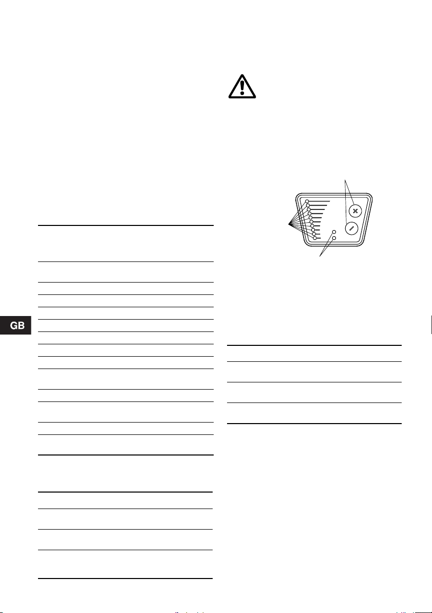
6.7 Indicator lights
The two indicator lights are used for fault and operating indication.
For position on pump, see fig. 13, section 7.2 Control
panel.
Master pump indicator lights:
The functions of the master pump indicator lights
apply to both the master pump and the slave pump.
A fault in the slave pump will thus be indicated on the
master pump.
Slave pump indicator lights:
The green indicator light on the slave pump will flash
on and off 20 times per minute to indicate correct
communication with the master pump.
The indicator lights of the slave pump can be activated briefly by pressing a button on the slave pump
control panel. Fault indication will then only apply to
the slave pump.
Note: When the R100 remote control communicates
with the master pump, the red indicator light will flash
TM01 0626 1797
rapidly.
Functions of indicator lights:
Indicator lights
Opera-
(red)
(green)
Off Off
Off
Perma-
nently on
Off Flashing
Perma-
nently on
Perma-
nently on
Perma-
nently on
Perma-
nently on
Flashing
See also section 8. Fault finding chart.
DescriptionFault
tion
The electricity supply has
been switched off.
The pump is operating.
The pump has been set to
stop.
The pump has stopped because of a fault. Restarting
will be attempted. (It may
Off
be necessary to restart the
pump manually by resetting
the fault indication.)
The pump is operating, but
it has been stopped because of a fault.
Note: If there is no differential pressure or temperature sensor signal, the
pump will continue operating according to the max.
curve.
The pump has been set to
stop, but it has been
stopped because of a fault.
133
Page 12

6.8 External fault indications
The pump incorporates a fault signal output for a
potential-free fault signal via terminals 2 and 3.
The signal output of both the master pump and the
slave pump can be used.
• The function of the master pump signal output
applies to both the master pump and the slave
pump.
• The function of the slave pump signal output
applies only to the slave pump.
Functions of signal output:
Signal output Description
The electricity supply has been
132
132
NC NO C
132
NC NO C
12 3
NC NO C
12 3
NC NO C
12 3
NC NO C
Resetting of fault indications:
A fault indication can be reset in one of the following
ways:
• Briefly press "+" or "–" on the pump. This will not
influence the pump performance set.
• Briefly switch off the electricity supply to the
pump.
• By means of the R100, see section 7.3 R100.
The fault indication cannot be reset until the cause of
the fault has disappeared.
switched off.
The pump is operating.
The pump has been set to stop.
The pump has stopped because
of a fault. Restarting will be attempted. (It may be necessary to
restart the pump manually by
resetting the fault indication.)
The pump is operating, but it has
been stopped because of a fault.
Note: If there is no differential
pressure or temperature sensor
signal, the pump will continue
operating according to the max.
curve.
The pump has been set to stop,
but it has been stopped because
of a fault.
6.9 External analog 0-10 V controller
The pump has an input for an external 0-10 VDC
analog signal transmitter (terminals 11 and 12 in
master pump). Via this input, the pump can be controlled by an external controller if the pump has been
set to one of the following control modes:
• Constant curve.
The external analog signal will set the pump curve
within the range from the min. curve to the constant curve selected according to the characteristic in fig. 12.
• Pressure control.
The external analog signal will control the setpoint
for the pump head between the setpoint corresponding to the min. curve and the setpoint
selected according to the characteristic in fig. 12.
At an input voltage lower than 0.5 V, the pump will
operate according to the min. curve. The setpoint
cannot be changed.
The setpoint can only be changed when the input
voltage is higher than 0.5 V.
Head set/constant curve
Max. head/constant curve
mVH
Min.
curve
0
8 9 107654321
Fig. 12
Note:
• The max. curve input, terminals 7 and 10, must be
open.
• The min. curve input, terminals 7 and 9, must be
closed.
U
TM03 1648 2505
134
Page 13

6.10 External forced control
The pump incorporates inputs for external signals for
the forced-control functions:
• Start/stop of pump (terminals 7 and 8 in master
pump).
• Max. curve duty (terminals 7 and 10 in master
pump).
• Min. curve duty (terminals 7 and 9 in master
pump).
During forced control, the light fields/indicator lights
on the pump will show which function is active.
Functional diagram: Start/stop input:
Start/stop
H
Q
H
Q
Functional diagram: Max. curve input:
The max. curve input is only active if the start/stop
input is closed.
Max. curve
H
Q
H
Q
Normal duty
Stop
Normal duty
Max. curve
6.12 Bus communication
If the pump is to be connected to a PMU 2000 or
PCU 2000, it must be set to single-pump operation,
see supplement to these instructions.
The pump enables serial communication via an
RS-485 input. The communication is carried out
according to the Grundfos bus protocol, GENIbus,
and enables connection to the GRUNDFOS Pump
Management System 2000, a building management
system or another type of external control system.
Via the bus signal, it is possible to remote-set pump
operating parameters, such as desired head, temperature influence, operating mode, etc. At the same
time, the pump can provide status information about
important parameters, such as actual head, actual
flow, power input, fault indications, etc.
For further details, consult the operating instructions
for the GRUNDFOS Pump Management System
2000 or contact Grundfos.
Note: When the pump is controlled via a bus signal,
the number of settings available on the pump control
panel or via the R100 will be reduced.
The pump head and control mode can only be set via
the bus signal. The pump control panel or the R100
can only set the pump to max. curve and to stop.
However, an R100 is required if a number is to be
allocated to the pump. See also section 7.7 Priority
of settings.
6.13 Wireless remote control
For wireless operation and reading of data, use the
Grundfos remote control R100.
For application of the remote control, see section
7.3 R100.
Functional diagram: Min. curve input:
The min. curve input is only active if the start/stop
input is closed and the max. curve input is open.
Min. curve
H
Q
H
Q
Normal duty
Min. curve
(night-time duty)
6.11 Deactivating the control panel
Can be set by means of the R100.
The buttons on the master pump control panel can
be deactivated to prevent unauthorized persons from
operating the pump.
135
Page 14
7. Setting the pump
All control of the twin-head pump is carried out by
the master pump except when the pump is running
single-pump operation.
The slave pump will not respond to commands
(unless when in single-pump operation) from the
control panel, the R100 nor from external signal
transmitters but only to commands from the master
pump. All setting and reading of data must therefore
be done via the master pump.
The green slave pump indicator light will flash on and
off 20 times per minute to indicate correct communication between master and slave pump.
For the setting of the pump, use:
• Control panel.
• R100 remote control.
• Bus communication (not described in detail in
these instructions. Contact Grundfos).
The following table shows the application of the individual operating units and in which section the function has been described.
7.2 Control panel
Note: Only the control panel of the master pump is
active unless the pump is running single-pump operation.
At high liquid temperatures, the pump may
be so hot that only the buttons should be
touched to avoid burns.
The control panel, fig. 13, incorporates the following:
• Buttons, "+" and "–", for setting.
• Light fields, yellow, for indication of control mode
and pump head.
• Indicator lights, green and red, for operating and
fault indication, see section 6.7 Indicator lights.
Buttons
Light fields
Function
Proportional-pressure
control
Constant-pressure control 7.2.1 7.6.1
Setting of pump head 7.2.2 7.4.1
Max. curve duty 7.2.3 7.4.2
Min. curve duty 7.2.4 7.4.2
Constant curve duty – 7.4.2
Temperature influence – 7.6.3
Resetting of fault indications 7.2.6 7.4.3
Activation/deactivation of
pump buttons
Allocation of pump number – 7.6.5
Reading of various data –
Star t/ stop 7.2.5 7.4.2
Control of twin-head pumps
(change of factory setting)
"–" = not available with this operating unit.
Control
panel
7.2.1 7.6.1
– 7.6.4
7.5.1 -
7.5.7
– 7.6.6
7.1 Factory settings
UPED xx-60 UPED xx-120
Control mode
Head
Control of
twin-head
pump
136
Proportional
pressure
3 m at maximum
flow, see fig. 15
Alternating Alternating
Proportional
pressure
6 m at maximum
flow, see fig. 17
R100
Fig. 13
7.2.1 Setting of control mode
Description of function, see section 6.2 Control
modes.
When the buttons "+" and "–" are pressed simultaneously, the light fields will indicate the selected control
mode:
Light fields Control mode
Top + bottom
light fields flashing
Middle light fields
flashing
None of the light
fields are on
If the buttons are pressed for more than 5 sec., the
control mode will change over to constant pressure
and proportional pressure respectively. This means
that constant curve duty is deactivated if selected by
means of the R100.
Indicator lights
Proportional pressure
Constant pressure
Constant curve
TM00 4431 0603
Page 15

7.2.2 Setting of pump head
The desired pump head is set by pressing the button
"+" or "–".
The light fields on the control panel will indicate the
head set.
The table below shows examples of pump head settings indicated by the light fields.
Constant-pressure control Proportional-pressure control
mH
5
4
3
2
UPED 100-60
1
0
Fig. 14
Light field 5 is activated, indicating a desired head of 3 metres.
H m
10
8
6
UPED 50-120
UPED 65-120
UPED 80-120
4
2
1
0
Fig. 16
Light fields 5 and 6 are activated, indicating a desired head
of 5.5 metres.
mH
5
4
3
2
1
QQ
0
TM00 4435 1597
QQ
TM00 4434 1597
Fig. 15
Light fields 5 and 6 are activated, indicating a desired head
of 3 metres at maximum flow.
H m
10
8
6
4
2
QQ
0
TM00 4433 1597
Fig. 17
QQ
TM00 4432 2297
Light fields 7 and 8 are activated, indicating a desired head
of 6 metres at maximum flow.
137
Page 16

7.2.3 Setting to max. curve duty
Description of function, see section 6.4 Max. or min.
curve duty.
Press "+" continuously to change over to the max.
curve of the pump (top light field flashes), see fig. 18.
To change back, press "–" continuously until the
desired head is indicated.
H
Max. curve
QQ
Fig. 18
7.2.4 Setting to min. curve duty
Description of function, see section 6.4 Max. or min.
curve duty.
Press "–" continuously to change over to the min.
curve of the pump (bottom light field flashes), see
fig. 19. To change back, press "+" continuously until
the desired head is indicated.
H
QQ
Min. curve
Fig. 19
7.2.5 Start/stop of pump
Stop the pump by continuously pressing "–" until
none of the light fields are activated. When the pump
is stopped, the green indicator light will be flashing.
Start the pump by continuously pressing "+" until the
desired head is indicated.
If the pump is to be inoperative for a period, it is
recommended to use the start/stop input, the R100
or to switch off the electricity supply. In this way, the
pump head setting will remain unchanged when the
pump is to be started again.
7.2.6 Resetting of fault indications
To reset fault indications, briefly press "+" or "–".
This will not influence the pump performance set.
If the fault has not disappeared, the fault indication
will reappear.
TM00 4436 4596TM00 4437 4596
138
Page 17
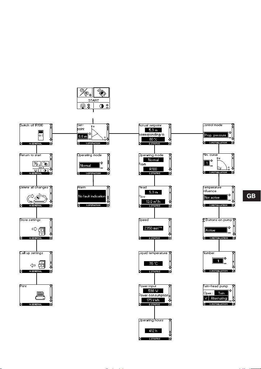
7.3 R100
The pump is designed for wireless communication
with the Grundfos remote control R100. The R100
communicates with the pump via infra-red light.
During communication, the R100 must be pointed at
the control panel on the master pump. When the
R100 is communicating with the pump, the red indicator light will flash rapidly.
The R100 offers additional possibilities of setting and
status displays for the pump.
The displays are divided into four parallel menus,
see fig. 20:
0. GENERAL, see operating instructions for R100
1. OPERATION
2. STATUS
3. INSTALLATION
The number stated at each individual display in
fig. 20 refers to the section in which the display is
described.
0. GENERAL
1. OPERATION 2. STATUS
7.4.1
7.4.2
7.4.3
7.5.1
7.5.2
7.5.3
7.5.4
7.5.5
7.5.6
3. INSTALLATION
7.6.1
7.6.2
7.6.3
7.6.4
7.6.5
7.6.6
Fig. 20
7.5.7
139
Page 18

7.4 Menu OPERATION
When communication has been established, menu
OPERATION appears in the display.
7.4.1 Setpoint
This display depends on the control mode selected
in the display "Control mode" in menu INSTALLATION.
If the pump is remote- or forced-controlled via external signals, the number of possible settings will be
reduced, see section 7.7 Priority of settings.
Attempts to change the settings will result in an indication in the display saying that the pump is remotecontrolled and changes therefore cannot be made.
The following example of display will appear if the
pump is in constant-pressure control mode.
In this display, the desired head is set.
Furthermore, it is possible to choose between the
following operating modes:
• Stop,
• Min. (min. curve),
• Max. (max. curve).
This display will be a little different in the case of pro-
portional-pressure control or constant curve duty.
The actual duty point of the pump is indicated by a
square in the Q/H field. The pump cannot register
very low flow rates, and the square will therefore disappear.
7.4.2 Operating mode
Select one of the following operating modes:
• Stop,
• Min. (min. curve),
• Normal (proportional pressure, constant pressure
or constant curve),
• Max. (max. curve).
7.4.3 Fault indications
If the pump is faulty, the cause will appear in this
display.
Possible causes:
• Phase failure,
• Pump blocked,
• Undervoltage,
• Defective pressure/temperature sensor,
• Internal fault (fault in electronics),
• Fault in master/slave communication.
The fault indication can be reset in this display. If the
fault cause has not disappeared when resetting is
attempted, this will be indicated in the display.
7.5 Menu STATUS
The displays appearing in this menu are status displays only. It is not possible to change or set values.
The actual values in the display are stated as a
guide.
7.5.1 Actual setpoint
Field "Actual setpoint":
Actual setpoint of pump.
Field "corresponding to":
Actual setpoint in % of the setpoint set if the pump is
connected to an external analog 0-10 V signal transmitter or if temperature influence or proportionalpressure control is activated.
7.5.2 Operating mode
This display shows the actual operating mode (Stop,
Min., Normal or Max.) and where is was selected
(Pump, R100, BUS or External).
140
Page 19

7.5.3 Head and flow
Very low flows cannot be registered, and the R100
will show "<" in front of the lowest possible value of
the pump in question.
7.5.4 Speed
The actual pump speed.
7.5.5 Liquid temperature
The actual temperature of the pumped liquid.
Because of the physical position of the sensor,
deviations in the temperature measuring may occur,
e.g. at high liquid temperatures and/or low ambient
temperatures.
7.5.6 power input and power consumption
7.6 Menu INSTALLATION
In this menu, the settings are chosen that should be
considered when installing the pump.
7.6.1 Control mode
Description of function, see section 6.2 Control
modes or section 6.5 Constant curve duty.
Select one of the following control modes:
• Prop. pressure (proportional pressure),
• Const. pressure (constant pressure),
• Const. curve (constant curve).
Setting of setpoint or curve is carried out in display
7.4.1 Setpoint in menu OPERATION.
7.6.2 Min. curve
Description of function, see section 6.4 Max. or min.
curve duty.
In this display, it is possible to choose between two
min. curves. The curve is used when the operating
mode "min. curve" is selected.
7.6.3 Temperature influence
Description of function, see section 6.6 Temperature
influence.
.
Actual power input and power consumption of the
pump.
The value of power consumption is an accumulated
value and cannot be set to zero.
7.5.7 Operating hours
Operating hours of the pump.
The value of operating hours is an accumulated
value and cannot be set to zero.
The temperature influence function can be activated
in this display.
In the case of temperature influence, the pump must
be installed in the flow pipe. It is possible to choose
between maximum temperatures of 50°C and 80°C.
The temperature influence function will be active
only in constant or proportional-pressure control
mode.
When the temperature influence is active, a small
thermometer is shown in the display "Setpoint" in
menu OPERATION, see 7.4.1 Setpoint.
Note: If the pump is controlled via bus, temperature
influence cannot be set by means of the R100.
141
Page 20

7.6.4 Buttons on pump
To prevent unauthorized persons from operating the
pump, the function of the buttons "+" and "–" can be
deactivated in this display. The buttons can be reactivated only by means of the R100.
The buttons can be set to:
• Active,
• Not active.
7.6.5 Pump number
A number between 1 and 64 can be allocated to a
pump or can be changed so that the R100 or Pump
Management System 2000 can distinguish between
two or more pumps.
The Pump Management System 2000 can, however,
only accept the numbers 1 to 8.
7.6.6 Twin-head pump
3
This display offers the following options:
Selection of operating mode for twin-head pump:
If field 1 reads "Twin", field 2 offers the choice
between three operating modes:
• Alternating (alternating operation),
• Synchron. (synchronous operation),
• Standby (standby operation).
Description of function, se section 6.1 Control of
twin-head pumps.
Setting the pump to single-pump operation:
In the single-pump operation mode, the master and
slave pumps run independently of each other without
internal communication and with a sensor each.
To set the pump to this operating mode, the communication between master and slave is to be disconnected in one of the following ways:
1
2
1. If the master and slave pumps are connected
correctly:
1. Point the R100 at the master pump.
2. Choose "Single" in field 1.
3. Press "OK".
2. If there is a fault in the master-slave commu-
nication (red indicator lights of both pumps
are on):
1. Point the R100 at the master pump.
2. Choose "Single" in field 1.
3. Press "OK".
The master pump will now be running like
an ordinary single-head pump and the red
indicator light will go out.
4. Switch the R100 off and on again.
5. Point the R100 at the slave pump.
Field 1 is already reading "Single".
6. Press "OK" twice in field 1.
The slave pump is now running like a
The slave pump will now be running according to the
factory settings unless its settings have been
changed.
Setting the pump to twin-pump operation:
If the pump is running like a single-head pump, the
communication can be restored in the following way:
1. Check that the bus cable between master and
2. Check that both pump heads are connected to
3. Check that the operating mode of the slave pump
4. Check that the slave pump has been set to
5. Point the R100 at the master pump.
6. Choose "Twin" in field 1.
7. Press "OK".
8. Press "+" or "–" on the control panel of the
* If correct connection was not established because
single-head pump.
slave pump is connected to the pump heads.
the mains supply.
is "Normal".
"Single" in the display "Twin-head pump".
After a short while, the green indicator light on
the slave pump will start flashing rapidly for
5 seconds, indicating that the pump is ready to
be the slave pump of a twin-head pump. (If the
pump is installed in a bus system with many
pumps, the green indicator lights of all possible
slave pumps in the system will start flashing.)
selected slave pump (while the light is flashing *).
The light fields of the slave pump will go out and
the green indicator light will be flashing 20 times
per minute to indicate that correct connection has
been established.
5 seconds passed before "+" or "–" was pressed,
the red indicator light of the master pump will be
on. Go through the procedure all over again to
establish connection.
142
Page 21

Confirmation of correct connection:
1. Point the R100 at the master pump.
2. Press "OK" in field 3.
If the connection has been correctly established,
the green indicator light on the slave pump will be
flashing rapidly to indicate this.
7.7 Priority of settings
The forced-control signals will influence the settings
available on the pump and with the R100. By means
of the pump control panel or the R100, the pump can
always be set to max. curve duty or to stop.
If two or more functions are activated at the same
time, the pump will operate according to the function
with the highest priority.
The priority of the settings is as shown in the following table:
Without bus signal:
:
Possible settings
Priority
1Stop
2Max. curve
3 Stop
4 Max. curve
5 Min. curve Min. curve
6 Setting of head Setting of head
Example: If, via an external signal, the pump has
been forced to operate according to the max. curve,
the pump control panel or the R100 can only set the
pump to stop.
With bus signal:
:
Priority
1 Stop
2 Max. curve
3 Stop Stop
4
5 Min. curve Min. curve
6
Example: If, via an external signal, the pump has
been forced to operate according to the max. curve,
the pump control panel, the R100 or the bus signal
can only set the pump to stop.
Pump control
panel or R100
Possible settings
Pump
control
panel or
R100
External
signals
Max.
curve
External
signals
Bus
signal
Max.
curve
Setting of
head
8. Fault finding chart
Before removing the terminal box cover,
make sure that the electricity supply has
been switched off for at least 5 minutes.
The pumped liquid may be scalding hot
and under high pressure. Before any
removal or dismantling of the pump, the
system must therefore be drained or the
isolating valves on either side of the pump
must be closed.
• Only the indicator lights of the master pump are
active and they will therefore indicate fault no matter if the fault is in the master or the slave pump.
• The indicator lights of the slave pump can be activated briefly by pressing a button on the slave
pump control panel. Fault indication will then only
apply to the slave pump.
• The indicator lights mentioned in the fault finding
chart are the indicator lights of the master pump.
143
Page 22

Fault Cause Remedy
None of the pumps are
running.
None of the indicator
lights are on.
The pump is not running.
The green indicator light
is flashing.
Both pumps have stopped
due to a fault.
The red indicator light is
on and the green indicator light is off.
The pump is running, but
has been stopped due to
a fault.
The red and green indicator lights are on.
The pump has been set to
stop, but has been
stopped due to a fault.
The red indicator light is on
and the green indicator
light is flashing.
Noise in the system.
The green indicator light
is on.
One fuse in the installation is blown. Replace the fuse.
The current-operated or voltage-operated
circuit breaker has tripped out.
The pump is defective. Repair or replace the pump.
The pump has been stopped in one of the
following ways:
1. With the button "–".
2. With the R100.
3. External on/off switch in position off.*
4. Via bus signal.*
* The fault can be temporarily corrected by selecting max. curve duty on the
pump or with the R100, as external forced-control signals will be ignored.
Electricity supply failure (e.g. undervoltage).
Missing phase (the pump runs for 2 minutes and then stops).
The pumps are blocked and/or impurities
in the pumps.
Fault in electronics. Contact Grundfos.
The differential pressure and temperature
sensor is defective.
The master and slave pumps have been
stopped due to a fault. One or both
pumps have restarted automatically.
The master pump is or has been stopped
due to a fault.
The slave pump is or has been stopped
due to a fault.
The differential pressure and temperature
sensor is defective.
The master and slave pumps have been
stopped due to a fault.
The master pump is or has been stopped
due to a fault.
The slave pump is or has been stopped
due to a fault.
Air in the system. Vent the system.
The flow is too high. Reduce the head (setpoint) and pos-
The pressure is too high. Reduce the head (setpoint) and pos-
Cut in the circuit breaker.
1. Start the pump by pressing "+".
2. Start the pump with the R100 or
by pressing "+".
3. Switch on the on/off switch.*
4. Start the pump via bus signal.*
Check that the electricity supply falls
within the specified range.
Check fuse and connections.
Remove the inspection screw and
turn the rotor by means of a screwdriver inserted into the slot in the
shaft end, and/or dismantle and
clean the pump.
Check sensor connection. Replace,
if necessary.
Reset fault indication.
Check sensor connection.
Replace, if necessary.
Reset fault indication.
sibly change over to constant pressure.
sibly change over to proportional
pressure.
144
Page 23

Fault Cause R emedy
Noise in the pump.
The green indicator light
is on.
Insufficient heat in some
places in the heating system.
See also section 6.7 Indicator lights.
Note: The R100 can also be used for fault finding.
Air in the pump. Vent the pump.
The inlet pressure is too low. Increase the inlet pressure and/or
The flow is too low. Increase the head (setpoint) and/or
check air volume in the expansion
tank (if installed).
change over to constant pressure.
9. Megging
Megging of an installation incorporating an UPED
pump is not allowed, as the built-in electronics may
be damaged. If megging of the pump is necessary,
the pump should be electrically separated from the
installation.
The master and slave pumps must be megged separately.
Megging of the pump can be carried out as
described below.
Megging of UPED pumps
1. Switch off the electricity supply.
2. Remove the wires from terminals L1, L2 and L3 and
the earth wire (see B).
3. Short-circuit terminals L1, L2 and L3 using two short
wires (see D).
4. Remove the wire for electronics frame connection
(see A).
5. Test between terminals L1/L2/L3 and earth (see C).
Maximum test voltage: 1500 VAC/DC.
Note: Never test between supply terminals (L1, L2 and
L3).
Maximum permissible leakage current: < 20 mA.
6. Fit the wire for electronics frame connection (see A).
7. Remove the short wires between terminals L1, L2 and
L3 (see D).
8. Fit the supply wires to terminals L1, L2 and L3 and
the earth wire (see B).
9. Switch on the electricity supply.
D
A
C
B
TM00 9122 4596
9.1 High-voltage test
If it is necessary to high-voltage test the UPED
pump, the megging instructions must be followed,
see section 9. Megging.
10. Technical data
Supply voltage
3 x 400-415 V ±10%, 50 Hz.
Motor protection
The pump requires no external motor protection.
Enclosure class
IP 42.
Relative air humidity
Maximum 95%.
Ambient temperature
0°C to +40°C.
145
Page 24

Temperature class
TF110 to CEN 335-2-51.
Liquid temperature
Maximum +110°C.
Continuously: +15°C to +95°C.
Pumps in domestic hot-water systems:
Continuously: +15°C to +60°C.
To avoid condensation in the terminal box and the
stator, the pumped liquid temperature must always
be higher than the ambient temperature. See the
table below:
Ambient
temperature
[°C]
15 15 110
20 20 110
25 25 110
30 30 110
35 35 90
40 40 70
System pressure
The system pressure is indicated on the pump
flanges:
Pump type PN 6 PN 10
UPED 50-120 z 4
UPED 65-120 z 4
UPED 80-120
UPED 100-60
Inlet pressure
The following minimum pressures must be available
at the pump inlet during operation:
Liquid temperature
Min. [°C] Max. [°C]
Number
PN 6/
PN 10
z 4
z 8
z 4
z 8
of bolt
holes
EMC (electromagnetic compatibility)
EN 61800-3.
Sound pressure level
The sound pressure level of the pump is lower than
54 dB(A).
Leakage current
The pump mains filter will cause a discharge current
to earth during operation. I
Inputs and outputs
Start/stop input External potential-free switch.
Max. curve input
Min. curve input
Input for analog
0-10 V signal
Signal output Internal potential-free change-
Bus input Grundfos bus protocol,
Contact load:
5 V, 0.1 mA.
Screened cable.
Loop resistance:
Maximum 130 Ω/km.
Logical levels:
Logical zero: U < 1.5 V.
Logical one: U > 4.0 V.
External signal: 0-10 VDC.
Maximum load: 1 mA.
Screened cable.
over contact.
Maximum load:
250 V, 2 A AC1.
Minimum load: 5 V, 1 mA.
Screened cable.
GENIbus protocol, RS-485.
Screened cable.
Lead cross section:
0.25 - 1 mm².
Cable length:
Maximum 1200 m.
leakage
< 3.5 mA.
11. Disposal
This product or parts of it must be disposed of in an
environmentally sound way:
1. Use the public or private waste collection service.
2. If this is not possible, contact the nearest
Grundfos company or service workshop.
Liquid temperature
Pump type
UPED 50-120 0.4 0.7
UPED 65-120 0.9 1.2
UPED 80-120 1.6 1.9
UPED 100-60 0.95 1.25
146
75°C 90°C
[bar] [bar]
Subject to alterations.
Page 25

Rp 1/4
B3
B2
H3
H2
H1
L2
L3
B7
B6
B6
L1
B4
B5
M
UPED 50-120 UPED 65-120
PN 6 / PN 10 PN 6 / PN 10
L1 280 340
L2 126 153
L3 60 63
B2 205 205
B3 450 450
B4 225 225
B5 225 225
B7 240 240
H1 75 82
H2 277 290
H3 352 372
D1 50 65
D2 102 122
D3 110/125 130/145
D4 165 185
D5 14 /19 14/19
M M12 M12
D4
D2
D1
D5
D3
D3
TM02 0696 5000
170
Page 26

B3
H3
H2
H1
B7
B6
B6
D4
D3
D1
Rp 1/4
B2
L2
L3
B4
L1
B5
M
UPED 80-120 UPED 100-60
PN 6 PN 10 PN 6 PN 10
L1 360 360 450 450
L3 53 53 83 83
B2 205 205 205 205
B3 460 460 595 595
B4 225 225 280 280
B5 235 235 315 315
B7 240 240 280 280
H1 97 97 122 122
H2 294 294 313 313
H3 391 391 435 435
D1 80 80 100 100
D2 138 138 158 158
D3 150 160 170 180
D4 200 200 220 220
D5 19 19 19 19
M M16 M16 M16 M16
D2
D5
PN 6
PN 10
TM02 0695 5000
171
Page 27

3 x 400-415 V, UPED 50-120, UPED 65-120, UPED 80-120, UPED 100-60
L2
L1L3
10987654
321
1211
TM01 6419 2399TM01 6421 2399
172
Page 28

173
Page 29

174
Page 30

Denmark
GRUNDFOS DK A/S
Martin Bachs Vej 3
DK-8850 Bjerringbro
Tlf.: +45-8750 5050
Telefax: +45-87 50 51 51
Australia
GRUNDFOS Pumps Pty. Ltd.
P.O. Box 2040
Regency Park
South Australia 5942
Phone: +61-8-8461 4611
Telefax: +61-8-8346 7434
Austria
GRUNDFOS Pumpen Vertrieb Ges.m.b.H.
Grundfosstraße 2
A-5082 Grödig/Salzburg
Tel.: +43-6246 883 0
Telefax: +43-6246 883 60 / 883-30
Belgium
N.V. GRUNDFOS Bellux S.A.
Boomsesteenweg 81-83
B-2630 Aartselaar
Tél.: +32-3-870 7300
Télécopie: +32-3-870 7301
Belorussia
Представительство ГРУНДФОС в Минске
220090 Минск ул.Олешева 14
Теле фон: (8632) 62-40-49
Факс: (8632) 62-40-49
Bosnia/Herzegovina
GRUNDFOS Sarajevo
Paromlinska br. 16,
BiH-71000 Sarajevo
Phone: +387 33 713290
Telefax: +387 33 231795
Bulgaria
GRUNDFOS Bulgaria
BG-1421 Sofia
105-107 Arsenalski blvd.
Тел.: +359 2963 3820, 2963 5653
Факс: +359 2963 1305
Croatia
GRUNDFOS predstavništvo Zagreb
Cebini 37, Buzin
HR-10000 Zagreb
Phone: +385 1 6595 400
Telefax: +385 1 6595 499
Czech Republic
GRUNDFOS s.r.o.
Čapkovského 21
779 00 Olomouc
Phone: +420-585-716 111
Telefax: +420-585-716 299
Estonia
GRUNDFOS Pumps Eesti OÜ
Peterburi tee 44
11415 Tallinn
Tel: + 372 606 1690
Fax: + 372 606 1691
Finland
OY GRUNDFOS Pumput AB
Mestarintie 11
FIN-01730 Vantaa
Phone: +358-3066 5650
Telefax: +358-3066 56550
France
Pompes GRUNDFOS Distribution S.A.
Parc d’Activités de Chesnes
57, rue de Malacombe
F-38290 St. Quentin Fallavier (Lyon)
Tél.: +33-4 74 82 15 15
Télécopie: +33-4 74 94 10 51
Germany
GRUNDFOS GMBH
Schlüterstr. 33
40699 Erkrath
Tel.: +49-(0) 211 929 69-0
Telefax: +49-(0) 211 929 69-3799
e-mail: infoservice@grundfos.de
Service in Deutschland:
e-mail: kundendienst@grundfos.de
Greece
GRUNDFOS Hellas A.E.B.E.
20th km. Athinon-Markopoulou Av.
P.O . B ox 7 1
GR-19002 Peania
Phone: +0030-210-66 83 400
Telefax: +0030-210-66 46 273
Hungary
GRUNDFOS Hungária Kft.
Park u. 8
H-2045 Törökbálint,
Phone: +36-23 511 110
Telefax: +36-23 511 111
Ireland
GRUNDFOS (Ireland) Ltd.
Unit 34, Stillorgan Industrial Park
Blackrock
County Dublin
Phone: +353-1-2954926
Telefax: +353-1-2954739
Italy
GRUNDFOS Pompe Italia S.r.l.
Via Gran Sasso 4
I-20060 Truccazzano (Milano)
Tel.: +39-2-95838112
Telefax: +39-2-95309290 / 95838461
Latvia
SIA GRUNDFOS Pumps Latvia
Deglava biznesa centrs
Augusta Deglava ielā 60, LV-1035, Rīga
Tālr.: + 371 7 149 640, 7 149 641
Fakss: + 371 9 149 646
Lithuania
GRUNDFOS Pumps UAB
Smolensko g. 6
LT-03201 Vilnius
Tel: + 370 52 395 430
Fax: + 370 52 395 431
Netherlands
GRUNDFOS Nederland B.V.
Postbus 104
NL-1380 AC Weesp
Tel.: +31-294-492 211
Telefax: +31-294-492244 / 492299
Norway
GRUNDFOS Pumper A/S
Strømsveien 344
Postboks 235, Leirdal
N-1011 Oslo
Tlf.: +47-229 047 00
Telefax: +47-223 221 50
Poland
GRUNDFOS Pompy Sp. z o.o.
ul. Klonowa 23
Baranowo k. Poznania
PL-62-081 Przeźmierowo
Phone: (+48-61) 650 13 00
Telefax: (+48-61) 650 13 50
Portugal
Bombas GRUNDFOS (Portugal) Lda.
Rua Calvet de Magalhães, 241
Apartado 1079
P-2780 Paço de Arcos
Tel.: +351-1-4407600
Telefax: +351-1-4407690
România
GRUNDFOS Pompe România SRL
Bd. Biruintei, nr 103
Pantelimon county Ilfov
Phone: +40 21 200 4100
Telefax: +40 21 200 4101
E-mail: romania@grundfos.ro
Russia
ООО Грундф ос
Росс ия, 10954 4 Москва, Школьная 39
Тел. (+7) 095 737 30 00, 564 88 00
Факс (+7) 095 737 75 36, 564 88 11
E-mail grundfos.moscow@grundfos.com
Serbia
GRUNDFOS Predstavništvo Beograd
Dr. Milutina Ivkovića 2a/29
YU-11000 Beograd
Phone: +381-11-2647-877, 11-2647-496
Telefax: +381-11-2648-340
Slovenia
GRUNDFOS PUMPEN VERTRIEB Ges.m.b.H.,
Podružnica Ljubljana
Blatnica 1, SI-1236 Trzin
Phone: +386 1 563 5338
Telefax: +386 1 563 2098
E-mail: slovenia@grundfos.si
Spain
Bombas GRUNDFOS España S.A.
Camino de la Fuentecilla, s/n
E-28110 Algete (Madrid)
Tel.: +34-91-848 8800
Telefax: +34-91-628 0465
Sweden
GRUNDFOS AB
Lunnagårdsgatan 6
431 90 Mölndal
Tel.: +46-0771-32 23 00
Telefax: +46-31-331 94 60
Switzerland
GRUNDFOS Pumpen AG
Bruggacherstrasse 10
CH-8117 Fällanden/ZH
Tel.: +41-1-806 8111
Telefax: +41-1-806 8115
Taiwan
GRUNDFOS Pumps (Taiwan) Ltd.
7 Floor, 219 Min-Chuan Road
Taichung, Taiwan, R.O.C.
Phone: +886-4-2305 0868
Telefax: +886-4-2305 0878
Turkey
GRUNDFOS POMPA San. ve Tic. Ltd. Sti.
Gebze Organize Sanayi Bölgesi
Ihsan dede Caddesi,
2. yol 200. Sokak No. 204
41490 Gebze/ Kocaeli
Phone: +90 - 262-679 7979
Telefax: +90 - 262-679 7905
E-mail: satis@grundfos.com
Ukraine
ТОВ ГРУНДФОС Украина
ул. Владимирская, 71, оф. 45
г. Киев, 01033, Украин а,
Тел. +380 44 289 4050
Факс +380 44 289 4139
United Arab Emirates
GRUNDFOS Gulf Distribution
P.O. Box 16768
Jebel Ali Free Zone
Dubai
Phone: +971-4-8815166
Telefax: +971-4-8815136
United Kingdom
GRUNDFOS Pumps Ltd.
Grovebury Road
Leighton Buzzard/Beds. LU7 8TL
Phone: +44-1525-850000
Telefax: +44-1525-850011
U.S.A.
GRUNDFOS Pumps Corporation
17100 West 118th Terrace
Olathe, Kansas 66061
Phone: +1 913 227 3400
Telefax: +1 913 227 3500
Usbekistan
Представительство ГРУНДФОС в Ташкент е
700000 Ташкен т ул.Усм ан а
тупик 5
Телеф он: (3712) 55-68-15
Факс: (3712) 53-36-35
Носира 1-й
Addresses revised 10.01.2007
Page 31

Being responsible is our foundation
Thinking ahead makes it possible
Innovation is the essence
96421914 0307
Repl. V7140345 0801
www.grundfos.com
247
 Loading...