

Grundfos UPE 25-40, UPE 25-60, UPE 25-60 A, UPE 25-80, UPE 32-40 Installation And Operating Instructions Manual
...Page 1

UPE Series 2000
UPE 25-40, UPE 25-40 A, UPE 25-60, UPE 25-60 A, UPE 25-80,
UPE 32-40, UPE 32-60, UPE 32-80, UPE 40-80, UPE 50-80
GRUNDFOS INSTRUCTIONS
Installation and operating instructions
Page 2

Declaration of Conformity
We Grundfos declare under our sole responsibility that the products
UPE Series 2000, to which this declaration relates, are in conformity with the
Council Directives on the approximation of the laws of the EC Member States
relating to
– Machinery (98/37/EC).
Standard used: EN ISO 12100.
– Electromagnetic compatibility (89/336/EEC).
Standards used: EN 61 000-6-2 and EN 61 000-6-3.
– Electrical equipment designed for use within certain voltage limits
(73/23/EEC) [95].
Standards used: EN 60 335-1: 1994 and EN 60 335-2-51: 1997.
Konformitätserklärung
Wir Grundfos erklären in alleiniger Verantwortung, dass die Produkte
UPE Serie 2000, auf die sich diese Erklärung bezieht, mit den folgenden
Richtlinien des Rates zur Angleichung der Rechtsvorschriften der EGMitgliedstaaten übereinstimmen
– Maschinen (98/37/EG).
Norm, die verwendet wurde: EN ISO 12100.
– Elektromagnetische Verträglichkeit (89/336/EWG).
Normen, die verwendet wurden: EN 61 000-6-2 und EN 61 000-6-3.
– Elektrische Betriebsmittel zur Verwendung innerhalb bestimmter
Spannungsgrenzen (73/23/EWG) [95].
Normen, die verwendet wurden: EN 60 335-1: 1994 und
EN 60 335-2-51: 1997.
Déclaration de Conformité
Nous Grundfos déclarons sous notre seule responsabilité que les produits
Série UPE 2000 auxquels se réfère cette déclaration sont conformes aux
Directives du Conseil concernant le rapprochement des législations des Etats
membres CE relatives à
– Machines (98/37/CE).
Standard utilisé: EN ISO 12100.
– Compatibilité électromagnétique (89/336/CEE).
Standards utilisés: EN 61 000-6-2 et EN 61 000-6-3.
– Matériel électrique destiné à employer dans certaines limites de tension
(73/23/CEE) [95].
Standards utilisés: EN 60 335-1: 1994 et EN 60 335-2-51: 1997.
Dichiarazione di Conformità
Noi Grundfos dichiariamo sotto la nostra esclusiva responsabilità che i prodotti UPE Serie 2000 ai quali questa dichiarazione se riferisce sono conformi
alle Direttive del Consiglio concernente il ravvicinamento delle legislazioni
degli Stati membri CE relative a
– Macchine (98/37/CE).
Standard usato: EN ISO 12100.
– Compatibilità elettromagnetica (89/336/CEE).
Standard usati: EN 61 000-6-2 e EN 61 000-6-3.
– Materiale elettrico destinato ad essere utilizzato entro certi limiti di ten-
sione (73/23/CEE) [95].
Standard usati: EN 60 335-1: 1994 e EN 60 335-2-51: 1997.
Declaración de Conformidad
Nosotros Grundfos declaramos bajo nuestra única responsabilidad que los
productos Serie UPE 2000 a los cuales se refiere esta declaración son conformes con las Directivas del Consejo relativas a la aproximación de las
legislaciones de los Estados Miembros de la CE sobre
– Máquinas (98/37/CE).
Norma aplicada: EN ISO 12100.
– Compatibilidad electromagnética (89/336/CEE).
Normas aplicadas: EN 61 000-6-2 y EN 61 000-6-3.
– Material eléctrico destinado a utilizarse con determinadas límites
de tensión (73/23/CEE) [95].
Normas aplicadas: EN 60 335-1: 1994 y EN 60 335-2-51: 1997.
Declaração de Conformidade
Nós Grundfos declaramos sob nossa única responsabilidade que os produtos
Série 2000 da UPE aos quais se refere esta declaração estão em conformi-
dade com as Directivas do Conselho das Comunidades Europeias relativas à
aproximação das legislações dos Estados Membros respeitantes à
– Máquinas (98/37/CE).
Norma utilizada: EN ISO 12100.
– Compatibilidade electromagnética (89/336/CEE).
Normas utilizadas: EN 61 000-6-2 e EN 61 000-6-3.
– Material eléctrico destinado a ser utilizado dentro de certos limites de ten-
são (73/23/CEE) [95].
Normas utilizadas: EN 60 335-1: 1994 e EN 60 335-2-51: 1997.
∆ήλωση Συµµόρφωσης
Εµείς η Grundfos δηλώνουµε µε αποκλειστικά δική µας ευθύνη ότι τα προιόντα
Σειρά UPE 2000 συµµορφώνονται µε την Οδηγία του Συµβουλίου επί της
σύγκλισης των νόµων των Κρατών Mελών της Ευρωπαικής Ενωσης σε σχέση
µε τα
– Μηχανήµατα (98/37/EC).
Πρότυπο που χρησιµοποιήθηκε: EN ISO 12100.
– Ηλεκτροµαγνητική συµβατότητα (89/336/EEC).
Πρότυπα που χρησιµοποιήθηκαν: EN 61 000-6-2 και EN 61 000-6-3.
– Ηλεκτρικές συσκευές σχεδιασµένες γιά χρήση εντός ορισµένων ορίων
ηλεκτρικής τάσης (73/23/EEC) [95].
Πρότυπα που χρησιµοποιήθηκαν: EN 60 335-1: 1994 και
EN 60 335-2-51: 1997.
Overeenkomstigheidsverklaring
Wij Grundfos verklaren geheel onder eigen verantwoordelijkheid dat de produkten UPE Serie 2000 waarop deze verklaring betrekking heeft in
overeenstemming zijn met de Richtlijnen van de Raad inzake de onderlinge
aanpassing van de wetgevingen van de Lid-Staten betreffende
– Machines (98/37/EG).
Norm: EN ISO 12100.
– Elektromagnetische compatibiliteit (89/336/EEG).
Normen: EN 61 000-6-2 en EN 61 000-6-3.
– Elektrisch materiaal bestemd voor gebruik binnen bepaalde spannings-
grenzen (73/23/EEG) [95].
Normen: EN 60 335-1: 1994 en EN 60 335-2-51: 1997.
Försäkran om överensstämmelse
Vi Grundfos försäkrar under ansvar, att produkterna UPE Serie 2000, som
omfattas av denna försäkran, är i överensstämmelse med Rådets Direktiv om
inbördes närmande till EU-medlemsstaternas lagstiftning, avseende
– Maskinell utrustning (98/37/EC).
Använd standard: EN ISO 12100.
– Elektromagnetisk kompatibilitet (89/336/EC).
Använda standarder: EN 61 000-6-2 och EN 61 000-6-3.
– Elektrisk material avsedd för användning inom vissa spänningsgränser
(73/23/EC) [95].
Använda standarder: EN 60 335-1: 1994 och EN 60 335-2-51: 1997.
Vastaavuusvakuutus
Me Grundfos vakuutamme yksin vastuullisesti, että tuotteet UPE Sarja 2000,
jota tämä vakuutus koskee, noudattavat direktiivejä jotka käsittelevät EY:n
jäsenvaltioiden koneellisia laitteita koskevien lakien yhdenmukaisuutta seur.:
– Koneet (98/37/EY).
Käytetty standardi: EN ISO 12100.
– Elektromagneettinen vastaavuus (89/336/EY).
Käytetyt standardit: EN 61 000-6-2 ja EN 61 000-6-3.
– Määrättyjen jänniterajoitusten puitteissa käytettävät sähköiset laitteet
(73/23/EY) [95].
Käytetyt standardit: EN 60 335-1: 1994 ja EN 60 335-2-51: 1997.
Overensstemmelseserklæring
Vi Grundfos erklærer under ansvar, at produkterne UPE Serie 2000, som
denne erklæring omhandler, er i overensstemmelse med Rådets direktiver om
indbyrdes tilnærmelse til EF medlemsstaternes lovgivning om
– Maskiner (98/37/EF).
Anvendt standard: EN ISO 12100.
– Elektromagnetisk kompatibilitet (89/336/EØF).
Anvendte standarder: EN 61 000-6-2 og EN 61 000-6-3.
– Elektrisk materiel bestemt til anvendelse inden for visse spændings-
grænser (73/23/EØF) [95].
Anvendte standarder: EN 60 335-1: 1994 og EN 60 335-2-51: 1997.
Deklaracja zgodności
My, Grundfos, oświadczamy z pełną odpowiedzialnością, że nasze wyroby
UPE seria 2000 których deklaracja niniejsza dotyczy, są zgodne z
następującymi wytycznymi Rady d/s ujednolicenia przepisów prawnych krajów
członkowskich EG:
– maszyny (98/37/EG),
zastosowana norma: EN ISO 12100.
– zgodność elektromagnetyczna (89/336/EWG),
zastosowane normy: EN 61 000-6-2 i EN 61 000-6-3.
– wyposażenie elektryczne do stosowania w określonym zakresie napięć
(73/23/EWG) [95],
zastosowane normy: EN 60 335-1: 1994 i EN 60 335-2-51: 1997.
Bjerringbro, 15th June 2005
Svend Aage Kaae
Technical Director
2
Page 3

3
UPE Series 2000
UPE 25-40, UPE 25-40 A, UPE 25-60, UPE 25-60 A, UPE 25-80,
UPE 32-40, UPE 32-60, UPE 32-80, UPE 40-80, UPE 50-80
Installation and operating instructions 4
Montage- und Betriebsanleitung 27
Notice d’installation et d’entretien 52
Istruzioni di installazione e funzionamento 77
Instrucciones de instalación y funcionamiento 102
Instruções de instalação e funcionamento 126
Οδηγίες εγκατάστασης και λειτουργίας 151
Installatie- en bedieningsinstructies 176
Monterings- och driftsinstruktion 201
Asennus- ja käyttöohjeet 223
Monterings- og driftsinstruktion 245
Instrukcja montażu i eksploatacji 267
Page 4

4
CONTENTS
Page
1. General description 4
2. Applications 5
2.1 Pumped liquids 5
3. Installation 5
3.1 Terminal box positions 5
3.2 Changing the terminal box position 6
3.3 Non-return valve 6
3.4 Air separator pump 6
3.5 Frost protection 6
4. Electrical connection 7
5. Start-up 7
6. Functions 8
6.1 Control modes 8
6.2 Selection of control mode 9
6.3 Max. or min. curve duty 10
6.4 Constant curve duty 10
6.5 Temperature influence 10
6.6 Indicator lights 11
6.7 Expansion modules 11
6.8 External analog 0-10 V controller 15
6.9 Deactivating the control panel 15
6.10 Wireless remote control 15
7. Setting the pump 16
7.1 Factory settings 16
7.2 Control panel 16
7.3 Setting of pump head 17
7.4 R100 19
7.5 Menu OPERATION 20
7.6 Menu STATUS 20
7.7 Menu INSTALLATION 21
7.8 Priority of settings 22
8. Fault finding chart 23
9. Megging 24
10. Technical data 25
11. Disposal 26
1. General description
The UPE Series 2000 is a complete range of circulator pumps with integrated differential pressure control enabling adjustment of pump performance to the
actual system requirements. In many systems, this
will mean a considerable reduction in power consumption, prevent noise from thermostatic valves
and similar fittings, and improve the control of the
system.
The desired head can be set on the pump control
panel.
These instructions apply to the pump types
UPE 25-40, UPE 25-40 A, UPE 25-60, UPE 25-60 A,
UPE 25-80, UPE 32-40, UPE 32-60, UPE 3 2-80,
UPE 40-80 and UPE 50-80.
The pump offers the following functions:
• Proportional pressure control (factory setting).
The head is changed in accordance with the flow
demand. The desired head can be set on the
pump control panel.
• Constant pressure control. A constant head is
maintained, irrespective of flow demand. The desired head can be set on the pump control panel.
• Constant curve duty. The pump runs at a constant speed on or between the max. and min.
curves.
• Temperature influence. The head varies depending on the liquid temperature.
• External fault signal via a potential-free output.
(Requires an MC 40/60 or MC 80 expansion
module.)
• External analog control of head or speed from
an external 0-10 V signal transmitter.
(Requires an MC 40/60 or MC 80 expansion
module.)
• External forced control via inputs for:
-Start/stop,
- Max. curve,
- Min. curve (night-time duty).
(Requires an MC xx or MB xx expansion mod ule.)
• Bus communication. As the UPE Series 2000 incorporates an input for bus communication, the
pump can be controlled and monitored by a
Grundfos Pump Management System 2000, a
building management system or another type of
external control system.
(Requires an MB 40/60 or MB 80 expansion
module.)
• Remote control . The pump can be operated by
means of the Grundfos wireless remote control
R100.
Before beginning installation procedures,
these installation and operating instructions should be studied carefully. The installation and operation should also be in
accordance with local regulations and accepted codes of good practice.
Page 5

5
2. Applications
The UPE Series 2000 is designed for circulating liquids in heating systems. The pumps can also be
used in domestic hot-water systems.
UPE Series 2000 is suitable for:
• systems w ith a constant flow where it is desirable to optimize the setting of the pump duty point
and
• systems w ith variable flow-pipe temperatures.
2.1 Pumped liquids
Thin, clean, non-aggressive and non-explosive liquids, not containing solid particles, fibres or mineral
oils.
In heating systems, the water should meet the requirements of accepted standards on water quality in
heating systems, e.g. the German standard
VDI 2035.
In domestic hot-water systems, it is advisable to
use UPE pumps only for water with a degree of hardness lower than approx. 14°dH.
For water with a higher degree of hardness a directcoupled TPE pump is recommended.
3. Installation
When installing pumps, types UPE 32-80 F,
UPE 40-80 F and UPE 50-80 F, with oval bolt holes
in the pump flange, washers must be used as shown
in fig. 1.
Fig. 1
See mounting dimensions at the end of these instructions.
The pump must be installed with the motor shaft horizontal, fig. 2.
Fig. 2
Arrows on the pump housing indicate the liquid flow
direction through the pump, fig. 3.
Fig. 3
3.1 Terminal box positions
The terminal box can be turned to the positions
shown in figure 4. However, these positions must be
checked with the “x” markings indicated in the tables
below:
The pump must not be used for the transfer of inflammable liquids such as diesel
oil, petrol or similar liquids.
Care should be taken to ensure that persons cannot accidentally come into contact with hot surfaces of the pump.
Installation
Pump
Washer
TM01 0683 1997
TM00 4551 3394TM00 4452 3394
Pumps without insulation kit
Fig. 4 A B C D (E) (F)
UPE 25-40 x x x x (x) (x)
UPE 25-40 A* x x (x)
UPE 25-60 x x x x (x) (x)
UPE 25-60 A* x x (x)
UPE 25-80 x x (x)
UPE 32-40 x x x x (x) (x)
UPE 32-60 x x x x (x) (x)
UPE 32-80 x x (x)
UPE 40-80 x x (x)
UPE 50-80 x x (x)
Page 6

6
* UPE 25-40 A and UPE 25-60 A pumps, which have
a socket for an automatic air vent, must be
mounted in pipes with upward liquid flow.
Fig. 4
Note:
Pos. E and F: This terminal box position is not re-
commended.
Pos. G and H: This terminal box position is not
allowed.
3.2 Changing the terminal box position
Change the terminal box position as follows:
1. Remove the four screws holding the pump head.
2. Turn the pump head to the required position.
3. Replace the four screws and tighten securely.
3.3 Non-return valve
If a non-return valve is fitted in the pipe system, see
fig. 5, it must be ensured that the minimum discharge
pressure is always higher than the closing pressure
of the valve. This is especially important in proportional-pressure control mode (reduced head at low
flows).
Fig. 5
3.4 Air separator pump
Fig. 6
Do not start the pump until the system has been
filled with liquid and vented. Furthermore, the required minimum inlet pressure must be available at
the pump inlet, see section 10. Technical data.
3.5 Frost protection
If the pump is not being used during periods of frost,
the necessary steps must be taken to avoid frost
bursts.
Pumps with insulation kit
Fig. 4 A B C D (E) (F)
UPE 25-40 x x (x)
UPE 25-40 A* x (x)
UPE 25-60 x x (x)
UPE 25-60 A* x (x)
UPE 25-80 x x (x)
UPE 32-40 x x (x)
UPE 32-60 x x (x)
UPE 32-80 x x (x)
UPE 40-80 x x (x)
UPE 50-80 x x (x)
TM00 4453 1599
Before any dismantling of the pump, the
system must be drained or the isolating
valves on either side of the pump must be
closed as the pumped liquid may be scalding hot and under high pressure.
A
B
E
H
C
F
G
D
TM02 0640 0301
UPE 25-40 A and UPE 25-60 A pumps
must be fitted with an automatic air vent.
This must be fitted to the pump housing
before priming, fig. 6.
TM00 4454 3394
Page 7

7
4. Electrical connection
The electrical connection and protection should be
carried out in accordance with local regulations.
• The pump requires no external motor protection.
• The operating voltage and frequency are marked
on the pump nameplate. Please make sure that
the motor is suitable for the electricity supply on
which it will be used.
• Supply voltage:
1 x 230-240 V –10%/+6%, 50 Hz, PE.
• Mains connection is to be carried out as shown in
figs. 7 and 8.
Fig. 7
UPE 25-40, 25-40 A, 25-60, 25-60 A, 32-40 and
32-60
Mains connection of UPE xx-40 and UPE xx-60 is
shown in page 293.
Fig. 8
UPE 25-80, 32-80, 40-80 and 50-80
Mains connection of UPE xx-80 is shown in page
294.
5. Start-up
Do not start the pump until the system has been
filled with liquid and vented. Furthermore, the required minimum inlet pressure must be available at
the pump inlet, see section 10. Technical data.
The system cannot be vented through the pump.
To vent the pump, remove the vent screw, fig. 9,
switch on the electricity supply and ensure maximum
flow in the system.
When any remaining air has escaped, replace and
tighten the vent screw.
Fig. 9
The pump may be noisy, when first switched on, due
to air remaining in the chamber. The noise should
cease after a few minutes running.
After start-up, the desired operating mode and possibly pump head are set.
Never make any connections in the pump
terminal box unless the electricity supply
has been switched off for at least 5 minutes.
The earth terminal of the pump must be
connected to earth.
The pump must be connected to an external mains switch with a minimum contact
gap of 3 mm in all poles.
Megging must be carried out as described
in section 9. Megging.
TM00 4449 3301TM01 0462 3399
NL
LN
When the vent screw is removed, scalding
hot liquid under high pressure may escape. Care should be taken to ensure that
the escaping liquid does not cause personal injury or damage to other components.
TM00 4466 3394
Page 8
8
6. Functions
Some functions can only be selected by means of
the remote control R100. Where and how the different settings are made will appear from section
7. Setting the pump.
6.1 Control modes
UPE Series 2000 pumps can be set to the control
mode which is most suitable for the individual system.
Two control modes are available:
• Proportional pressure (factory setting).
• Constant pressure.
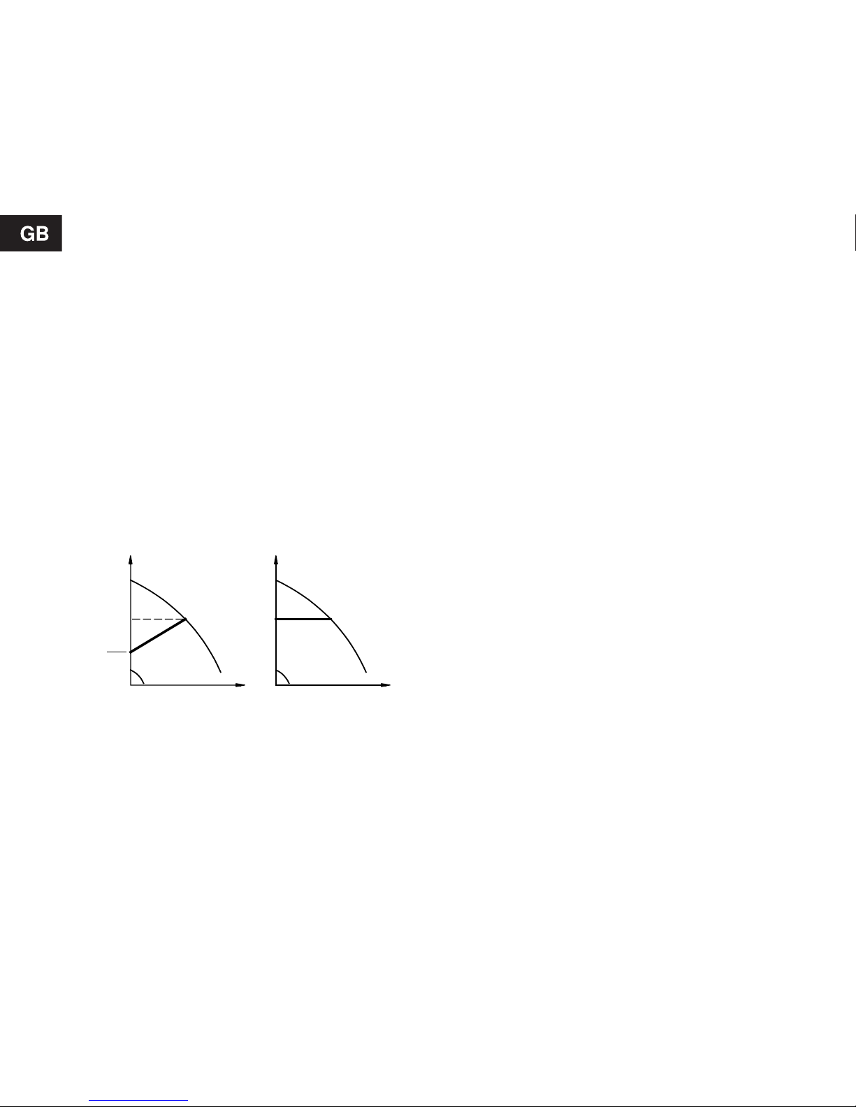
Proportional pressure control:
Can be set by means of the control panel or the
R100.
The pump head is reduced at falling water demand
and increased at rising water demand, see fig. 10.
Constant pressure control:
Can be set by means of the control panel or the
R100.
The pump maintains a constant pressure, irrespective of water demand, see fig. 10.
Fig. 10
TM00 5546 4596
2
H
Q
H
Q
H
set
Proportional
pressure
Constant
pressure
Control modes
H
set
H
set
H
set
Page 9

9
6.2 Selection of control mode
Systems with specified control mode:
If the control mode (proportional or constant pressure) and the pump head have been specified for the
system in which the pump is to be installed, the
pump should be set as specified. See section 7. Set-
ting the pump. If problems should arise, see section
8. Fault finding chart.
Systems with no specified control mode:
If the control mode and the pump head have not
been specified for the system (for instance, an uncontrolled standard pump is replaced by the UPE
pump), it is advisable to use the settings in the following table and in section 6.2.1 Settings in connec-
tion with pump replacement.
In systems
with
for instance
select this control mode:
relatively great
head losses in
the boiler circuit
and the distribution pipes
1. Two-pipe
heating systems with
thermostatic
valves and
with:
• a dimensioned pump head higher than 4 metres,
Proportional
pressure
• very long distribution pipes,
• strongly throttled pipe balancing valves,
• differential pressure regulators,
• great head losses in those parts of the system
through which the total quant ity of water flows (e.g.
boiler, heat exchanger and distribution pipe up to
the first branching) or
• low differential temperature.
2. Underfloor heating systems and one-pipe heating systems with thermostatic valves and great head losses in the boiler circuit.
3. Primary circuit pumps in systems with great head losses in the pr imary
circuit.
relatively small
head losses in
the boiler circuit
and the distribution pipes
1. Two-pipe
heating systems with
thermostatic
valves and:
• with a dimensioned pump head lower than 2 metres,
Constant
pressure
• dimensioned for natural circulation,
• with small head losses in those parts of the system
through which the total quant ity of water flows (e.g.
boiler, heat exchanger and distribution pipe up to
the first branching) or
• modified to a high differential temperature (e.g. district heating).
2. Underfloor heating systems with thermostatic valves.
3. One-pipe heating systems with thermostatic valves or pipe balancing
valves.
4. Primary circuit pumps in systems with small head losses in the primary
circuit.
Page 10
10
6.2.1 Settings in connection with pump
replacement
If an uncontrolled pump is to be replaced with a
UPE Series 2000, settings can be made according to
the tables below.
Read the tables as follows:
• If the maximum head of the existing pump is 5 me-
tres and the pump is running at maximum speed
under normal operating conditions, it is recommended to set the UPE pump to 2.5 metres and to
select proportional pressure.
• If, however, the existing pump is running at a re-
duced speed, it is recommended to set the pump
to 2 metres and to select constant pressure.
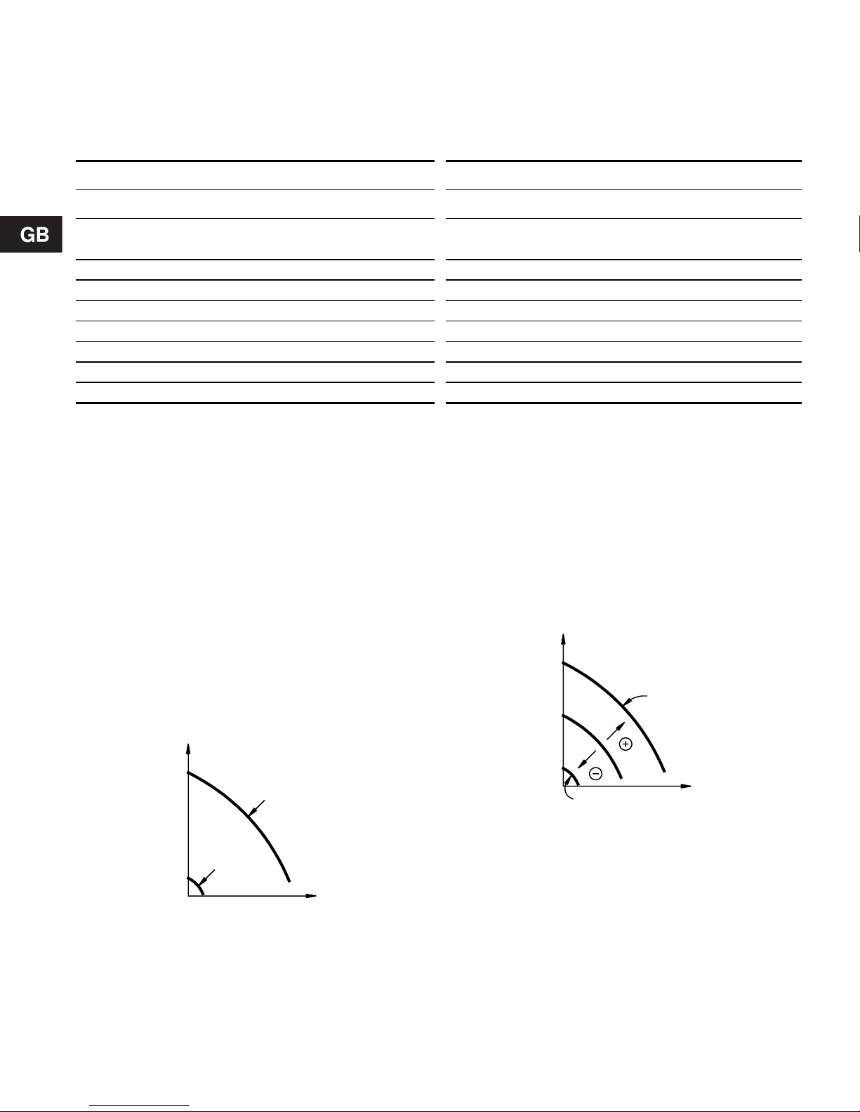
6.3 Max. or min. curve duty
Can be set by means of the control panel or the
R100.
The pump can be set to operate according to the
max. or min. curve, like an uncontrolled pump, see
fig. 11.
Fig. 11
The max. curve mode can be selected if an uncontrolled pump is required. In this operating mode, the
pump will operate independently of an external controller, if installed.
The min. curve mode can be used in periods in
which a minimum flow is required. This operating
mode is suitable for night-time duty.
6.4 Constant curve duty
Can be set by means of the R100.
The pump can be set to operate according to a constant curve, like an uncontrolled pump. Select one of
19 curves between the max. and min. curves, see
fig. 12.
Fig. 12
6.5 Temperature influence
Can be set by means of the R100.
When this function is activated in proportional or
constant control mode, the setpoint for head will be
reduced according to the liquid temperature. It is
possible to set temperature influence to function at
liquid temperatures below 80°C or below 50°C.
These temperature limits are called T
max.
.
The setpoint is reduced in relation to the head set
(= 100%) according to the characteristics below.
Existing pump at maximum speed Existing pump at reduced speed
Existing pump UPE Series 2000 Existing pump UPE Series 2000
Maximum
head [m]
Setting of
head [m]
Setting of
control mode
Maximum
head [m]
Setting of
head [m]
Setting of
control mode
21.5
Constant pressure
21
Constant pressure
32
Constant pressure
31.5
Constant pressure
42
Proportional pressure
41.5
Constant pressure
52.5
Proportional pressure
52
Constant pressure
63
Proportional pressure
62
Proportional pressure
73.5
Proportional pressure
72.5
Proportional pressure
84
Proportional pressure
83
Proportional pressure
TM00 5547 4596
Q
H
Min.
Max.
TM00 5548 4596
Q
H
Max.
Min.
Page 11

11
Fig. 13
In the above example, T
max.
= 80°C has been se-
lected. The actual liquid temperature T
actual
causes
the setpoint for head to be reduced from 100% to
H
actual
.
The temperature influence function requires:
• Proportional or constant pressure control mode.
• The pump must be installed in the flow pipe.
• System with flow-pipe temperature control
(e.g. according to outdoor temperature).
Temperature influence is suitable in:
• systems with variable flows (e.g. two-pipe heating
systems), in which the activation of the temperature influence function will ensure a further reduction of the pump performance in periods with small
heating demands and consequently a reduced
flow-pipe temperature, and
• systems with almost constant flows (e.g. one-pipe
heating systems and underfloor heating systems),
in which variable heating demands cannot be registered as changes in the head (as is the case
with two-pipe heating systems). In such systems,
the pump performance can only be adjusted by
activating the temperature influence function.
Selection of T
max.
In systems with a dimensioned flow-pipe temperature of:
• up to and including 55°C, select T
max.
= 50°C,
• above 55°C, select T
max.
= 80°C.
Specifically for UPE 25-40, 25-40 A and 32-40:
In the temperature range of 20 to 30°C, the pump automatically changes over to operation according to
an uncontrolled night-time duty curve.
6.6 Indicator lights
The two indicator lights are used for fault and operating indication.
For position on pump, see fig. 21, section 7.2 Control
panel.
Note: When the R100 remote control communicates
with the pump, the red indicator light will flash rapidly.
Functions of indicator lights:
See also section 8. Fault finding chart.
6.7 Expansion modules
The pump can be fitted with an expansion module
enabling communication with external signals (signal
transmitters).
Two types of expansion modules are available:
• Fault signal module, types MC 40/60 and MC 80.
• Bus module, types MB 40/60 and MB 8 0.
To fit a module, remove the existing terminal box
cover and fit the new cover incorporating the module.
The new cover increases the height of the terminal
box by approx. 20 mm, fig. 14.
Fig. 14
30%
100%
°CT
805020
H
H
Q
H
actual
T
actual
TM01 0626 1797
Indicator lights
Description Fault
(red)
Opera-
tion
(green)
Off Off
The electricity supply has
been switched off.
Off
Perma-
nently on
The pump is operating.
Off Flashing
The pump has been set
to stop.
Perma-
nently on
Off
The pump has stopped
because of a fault. Restarting will be attempted.
Perma-
nently on
Perma-
nently on
The pump is operating,
but it has been stopped
because of a fault.
Perma-
nently on
Flashing
The pump has been set
to stop, but it has been
stopped because of a
fault.
TM00 4463 3394
Never make any connections in the pump
terminal box unless the electricity supply
has been switched off for at least 5 minutes.
Page 12

12
6.7.1 Fault signal module
Via an internal relay, the fault signal module gives
access to a potential-free fault signal.
In addition to this fault signal output, the module has
four inputs for external signals for the forced-control
functions:
• Start/stop of pump.
• Max. curve duty.
• Min. curve duty (night-time duty).
• External analog control of head or speed from an
external 0-10 V signal transmitter.
Wiring diagrams of fault signal module:
Fig. 15
UPE 25-40, 25-40 A, 25-60, 25-60 A, 32-40 and
32-60 with MC 40/60
Note:
• If no external on/off switch is connected, the connection across terminals 7 and 8 should be maintained.
• If the 0-10 V input is used (terminals 11 and 12),
there must be a connection across terminals
7 and 9 (the input for the min. curve must be
closed).
• All cables used must be heat-resistant up to at
least +85°C.
• All cables used must be installed in accordance
with EN 60 204-1.
Fig. 16
UPE 25-80, 32-80, 40-80 and 50-80 with MC 80
TM01 1082 3697
NC
NO
C
213
9
87
10
11
12
DC 0-10 V
1
2
3
7
8
10
11
12
9
A
nalog 0-10 V
input
Max.
Fault signal
output
Start/stop
Mi
n. curve
(night-time duty)
M
ax. curve
Min.
Stop
TM01 1099 3697
• Wires connected to
- outputs 1 to 3,
- inputs 7 to 12 and
- supply terminals
must be separated from each other and
from the supply by reinforced insulation.
• All leads connected to a terminal block
must be tied up at the terminals.
DC 0-10 V
98710
NC
NO
C
213
11 12
3
7
2
1
8
9
10
11
12
Max.
Fault signal
out
p
ut
Start/stop
Mi
n. curve
(night-time duty)
M
ax. curve
A
nalog 0-10 V
input
Min.
Stop
Page 13

13
6.7.2 Bus module
The bus module enables serial communication with
the pump via an RS-485 input. The communication is
carried out according to the Grundfos bus protocol,
GENIbus, and enables connection to the Grundfos
Pump Management System 2000, a building management system or another type of external control
system.
Via the bus signal, it is possible to remote-set pump
operating parameters, such as desired head, temperature influence, operating mode, etc. At the same
time, the pump can provide status information about
important parameters, such as actual head, actual
flow, power input, fault indications, etc.
For further details, consult the operating instructions
for the Grundfos Pump Management System 2000 or
contact Grundfos.
Note: When a bus module is fitted to the pump, the
number of settings available on the pump control
panel and via the R100 will be reduced.
The pump head and control mode can only be set via
the bus signal. The pump control panel or the R100
can only set the pump to max. curve and to stop.
However, an R100 is required if a number is to be allocated to the pump. See also section 7.8 Priority of
settings.
In addition to the RS-485 input, the bus module has
three inputs for external signals for the forced-control
functions:
• Start/stop of pump.
• Max. curve duty.
• Min. curve duty (night-time duty).
If the pump has been forced-controlled to for in-
stance max. curve duty, the light fields on the pump
will indicate “max. curve”, see section 7.3.1 Setting
to max. curve duty.
Note:
• If no external on/off switch is connected, the connection across terminals 7 and 8 should be maintaine d.
• All cables used must be heat-resistant up to at
least +85°C.
• All cables used must be installed in accordance
with EN 60 204-1.
Wiring diagrams of bus module:
Fig. 17
UPE 25-40, 25-40 A, 25-60, 25-60 A, 32-40 and
32-60 with MB 40/60
Fig. 18
UPE 25-80, 32-80, 40-80 and 50-80 with MB 80
• Wires connected to
- inputs 7 to 10 and
- supply terminals
must be separated from each other and
from the supply by reinforced insulation.
• All leads connected to a terminal block
must be tied up at the terminals.
TM00 4474 3394TM00 4476 3394
Maks. kurve
Start/stop
Maks.Min.Stop
98710
Min. kurve
(Natsænkning)
AY
BUS
B
546
4
5
6
7
8
9
10
Start/stop
Min. curve
(night-time duty)
Max. curve
Max.
Min. kurve
(Natsænkning)
Maks. kurve
Start/stop
10
AY
BUS
B
546
Maks.Min.Stop
98710
6
5
4
7
8
9
Start/stop
Min. curve
(night-time duty)
Max. curve
Max.
Page 14

14
6.7.3 External fault signals
The expansion modules, type MC xx, have an output
from a potential-free changeover relay via terminals
2 and 3.
Functions of signal outputs:
The fault signal output is activated when the pump
registers a fault. The fault signal relay is activated together with the red indicator light on the pump.
Resetting of fault indications:
A fault indication can be reset in one of the following
ways:
• Briefly press “+” or “–” on the pump. This will not
influence the pump performance set.
• Briefly switch off the electricity supply to the
pump.
• By means of the R100, see section 7.4 R100.
The fault indication cannot be reset until the cause of
the fault has disappeared.
6.7.4 External forced control
The expansion modules MC xx and MB xx incorporate inputs for external signals for the forced-control
functions:
• Start/stop input (terminals 7 and 8).
• Max. curve duty (terminals 7 and 10).
• Min. curve duty (terminals 7 and 9).
During forced control, the light fields/indicator lights
on the pump will show which function is active.
Functional diagram: Start/stop input:
Functional diagram: Max. curve input:
The max. curve input is only active if the start/stop
input is closed.
Functional diagram: Min. curve input:
The min. curve input is only active if the start/stop input is closed and the max. curve input is open.
Indicator Lights
Internal
relay
Description
Fault
(red)
Opera-
tion
(green)
Contact
position
of termi-
nals
1, 2 and 3
Off Off
The electricity
supply has been
switched off.
Off
Perma-
nently
on
The pump is operating.
Off
Flash-
ing
The pump has
been set to stop.
Perma-
nently
on
Off
The pump has
stopped because
of a fault. Restarting will be attempted.
Perma-
nently
on
Perma-
nently
on
The pump is operating, but it has
been stopped because of a fault.
Perma-
nently
on
Flash-
ing
The pump has
been set to stop,
but it has been
stopped because
of a fault.
132
NC NO C
132
NC NO C
132
NC NO C
12 3
NC NO C
12 3
NC NO C
12 3
NC NO C
Start/stop
Normal duty
Stop
Max. curve
Normal duty
Max. curve
Min. curve
Normal duty
Min. curve
(night-time duty)
Q
H
H
Q
Q
H
Q
H
Q
H
Q
H
Page 15
15
6.8 External analog 0-10 V controller
The expansion modules, type MC xx, have an input
for an external 0-10 VDC analog signal transmitter
(terminals 11 and 12). Via this input, the pump can
be controlled by an external controller if the pump
has been set to one of the following control modes:
• Constant curve.
The external analog signal will set the pump curve
within the range from the min. curve to the constant curve selected according to the characteristic in fig. 19.
• Constant or proportion al pressure con trol.
The external analog signal will control the setpoint
for the pump head between the setpoint corresponding to the min. curve and the setpoint selected according to the characteristic in fig. 19.
At an input voltage lower than 0.5 V, the pump will
operate according to the min. curve. The setpoint
cannot be changed.
The setpoint can only be changed when the input
voltage is higher than 0.5 V.
Fig. 19
Note:
• The max. curve input, terminals 7 and 10, must be
open.
• The min. curve input, terminals 7 and 9, must be
closed.
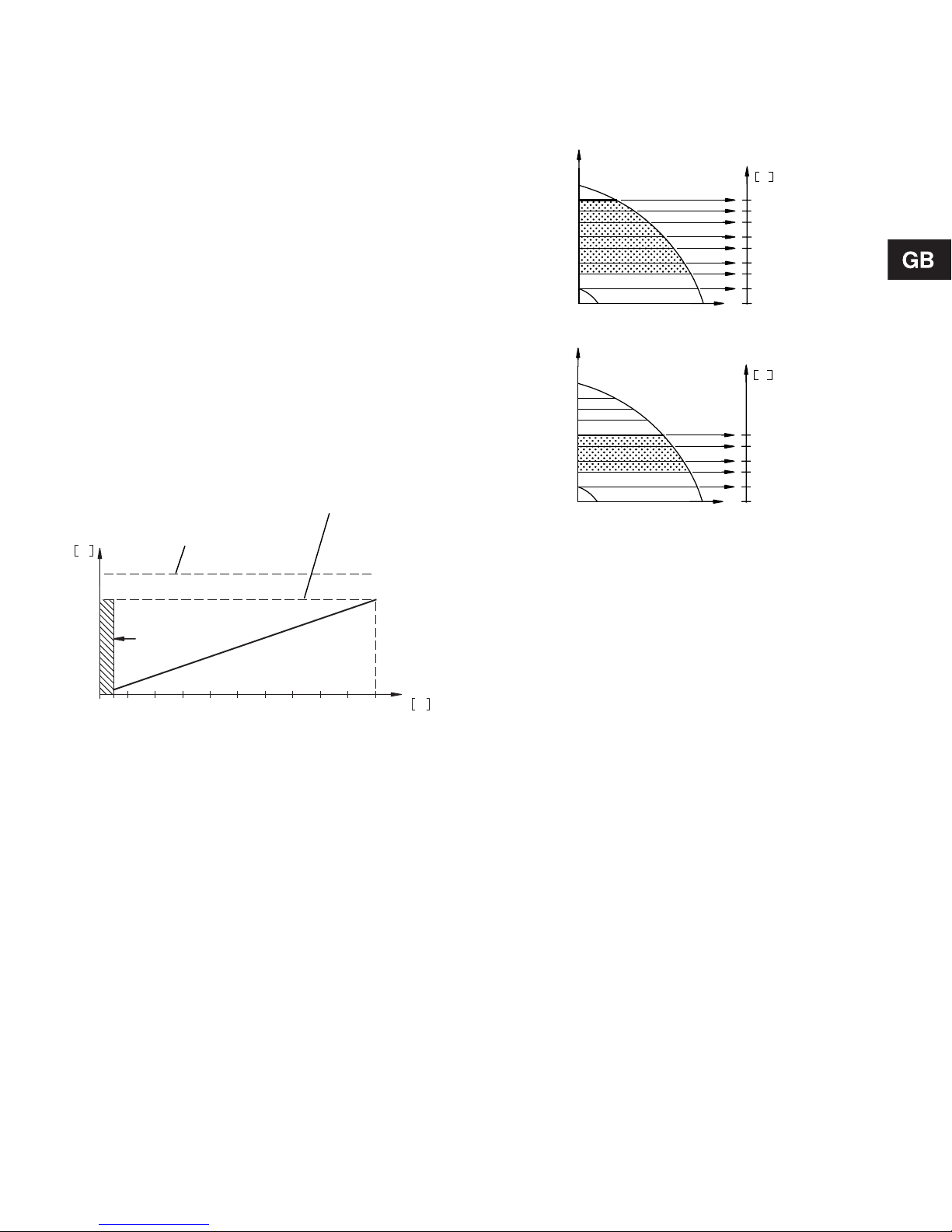
The examples below illustrate the use of an analog
control voltage in connection with a pump in constant-pressure control mode:
Fig. 20
Note: As will appear from the above figure, the
number of curves that can be selected via the external analog signal will depend on the setpoint of the
pump, H
set
.
6.9 Deactivating the control panel
Can be set by means of the R100.
The buttons on the pump control panel can be deactivated to prevent unauthorized persons from operating the pump.
6.10 Wireless remote control
For wireless operation and reading of data, use the
Grundfos remote control R100.
For application of the remote control, see section
7.4 R100.
8 9 107654321
mVH
U
0
TM03 1648 2505
Max. head/constant curve
Head set/constant curve
Min. curve
TM01 1384 4497TM01 1385 4497
10
8,6
7,2
5,8
4,3
3,0
1,5
0,5
0
V
U
H
set
10
7,5
5,0
2,5
0,5
0
V
U
H
set
H
set
Page 16
16
7. Setting the pump
For the setting of the pump, use:
• Control panel.
• R100 remote control.
• Bus communication
(not described in detail in these instructions.
Contact Grundfos).
The following table shows the application of the individual operating units and in which section the function has been described.
“-” = not available with this operating unit.
7.1 Factory settings
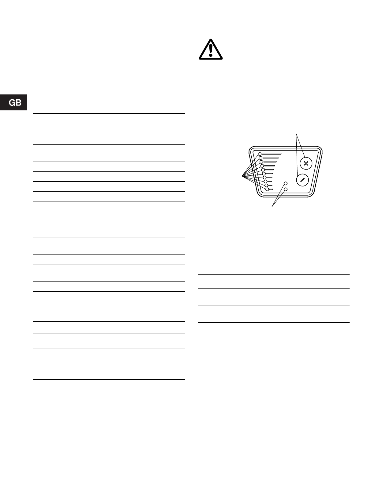
7.2 Control panel
The control panel, fig. 21, incorporates the following:
• Buttons, “+” and “–”, for setting.
• Light fields, yellow, for indication of control mode
and pump head.
• Indicator lights, green and red, for operating and
fault indication, see section 6.6 Indicator lights.
Fig. 21
7.2.1 Setting of control mode
Description of function, see section 6.1 Control
modes.
When the buttons “+” and “–” are pr essed sim ultaneously, the light fields will indicate the selected control
mode:
If the buttons are pressed for more than 5 sec., the
control mode will change over to constant pressure
and proportional pressure respectively.
Note:
If the pump has been set to constant curve duty and
the buttons “+” and “–” are pressed simultaneously,
the following applies:
• less than 5 sec.:
The light fields will not indicate the selected control mode.
• more than 5 sec.:
The control mode will not be changed.
Function
Control
panel
R100
Proportional pressure control
7.2.1 7.7.1
Constant pressure control 7.2.1 7.7.1
Setting of pump head 7.3 7.5.1
Max. curve duty 7.3.1 7.5.2
Min. curve duty 7.3.2 7.5.2
Constant curve duty - 7.5.2
Temperature influence - 7.7.2
Resetting of fault indica-
tions
7.3.4 7.5.3
Activation/deactivation of
pump buttons
- 7.7.3
Allocation of pump number - 7.7.4
Reading various data -
7.6.1-
7.6.6.
Start/stop 7.3. 3 7.5.2
Pump type Control mode Pump head
UPE xx-40 Proportional pressure
1.8 metres at maximum flow, see fig. 23
UPE xx-60 Proportional pressure
3 metres at maximum
flow, see fig. 25
UPE xx-80 Proportional pressure
4 metres at maximum
flow, see fig. 27
At high liquid temperatures, the pump may
be so hot that only the buttons should be
touched to avoid burns.
TM00 4431 0603
Light fields Control mode
Top + bottom
light fields flashing
Proportional pressure
Middle light field(s)
flashing
Constant pressure
Indicator lights
Buttons
Light fields
Page 17
17
7.3 Setting of pump head
The desired pump head (H
set
) is set by pressing the
button “+” or “–”.
The light fields on the control panel will indicate the
head set.
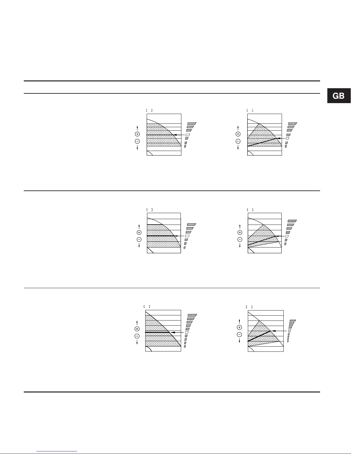
The table below shows examples of pump head set-
tings indicated by the light fields.
Constant pressure control Proportional pressure control
UPE 25-40
UPE 25-40 A
UPE 32-40
Fig. 22
Light field 4 is activated, indicating a desired head of 2.3 metres.
TM01 0631 1797
Fig. 23
Light field 3 is activated, indicating a desired head of 1.8 metres
at maximum flow.
TM01 0632 1797
UPE 25-60
UPE 25-60 A
UPE 32-60
Fig. 24
Light field 4 is activated, indicating a desired head of 3 metres.
TM00 4457 3394
Fig. 25
Light field 3 is activated, indicating a desired head of 3 metres at
maximum flow.
TM00 4458 0703
UPE 25-80
UPE 32-80
UPE 40-80
UPE 50-80
Fig. 26
Light field 5 is activated, indicating a desired head of 3.7 metres.
TM00 4459 3394
Fig. 27
Light fields 5 and 6 are activated.
This indicates a desired head lying between the two light fields of
4 metres at maximum flow.
TM00 4456 3394
QQ
3
0
0.5
1
1.5
2
2.5
3.5
4
m
H
QQ
3
0
0.5
1
1.5
2
2.5
3.5
4
m
H
Q
6
0
1
2
3
4
5
Q
m
H
Q
6
0
1
2
3
4
5
Q
m
H
Q
7
6
0
1
2
3
4
5
m
H
Q
7
6
0
1
2
3
4
5
m
H
Page 18
18
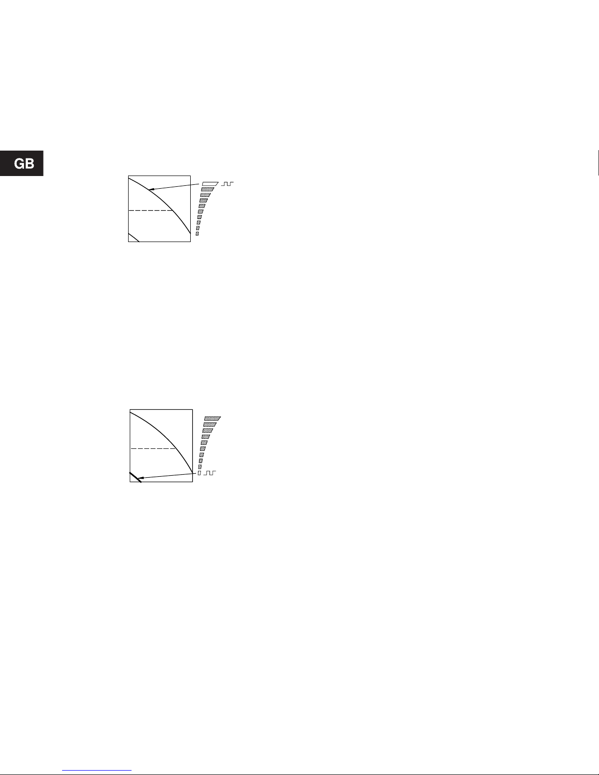
7.3.1 Setting to max. curve duty
Description of function, see section 6.3 Max. or min.
curve duty.
Press “+” continuously to change over to the max.
curve of the pump (top light field flashes), see fig. 28.
To change back, press “–” continuously until the desired head is indicated.
Fig. 28
7.3.2 Setting to min. curve duty
Description of function, see section 6.3 Max. or min.
curve duty.
Press “–” continuously to change over to the min.
curve of the pump (bottom light field flashes), see fig.
29. To change back, press “+” continuously until the
desired head is indicated.
Fig. 29
7.3.3 Start/stop of pump
Stop the pump by continuously pressing “–” until
none of the light fields are activated. When the pump
is stopped, the green indicator l ight will be flas hing.
Start the pump by continuously pressing “+” until the
desired head is indicated.
When the pump is to be inoperative for a period, it is
recommended to use the R100 remote control or to
switch off the electricity supply. In this way, the pump
head setting will remain unchanged when the pump
is to be started again.
7.3.4 Resetting of fault indications
To reset fault indications, briefly press “+” or “–” .
This will not influence the pump performance set.
If the fault cause has not disappeared, the fault indication will reappear.
TM00 4460 3394TM00 4461 3394
Q
H
Max. curve
Q
H
Min. curve
Page 19
19
7.4 R100
The pump is designed for wireless communication
with the Grundfos remote control R100. The R100
communicates with the pump via infra-red light.
During communication, the R100 must be pointed at
the pump control panel. When the R100 is communicating with the pump, the red indicator light will flash
rapidly. The R100 offers additional possibilities of
setting and status displays for the pump.
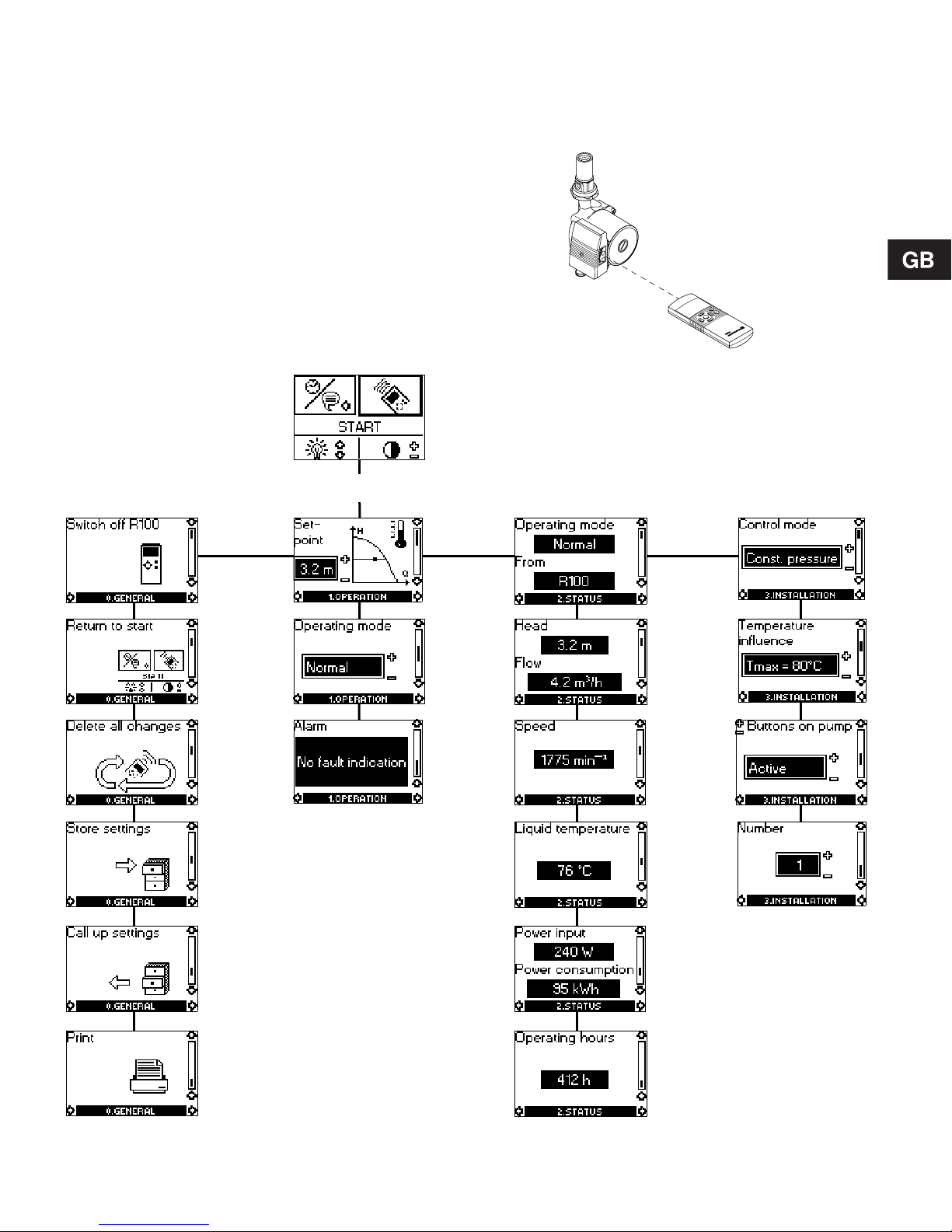
The displays are divided into four parallel menus,
see fig. 31:
0. GENERAL, see operating instructions for R100
1. OPERATION
2. STATUS
3. INSTALLATION
The number stated at each individual display in
fig. 31 refers to the section in which the display is described.
Fig. 30
Fig. 31
TM00 4465 33 94
R100
3. INSTALLATION0. GENERAL 1. OPERATION 2. STATUS
7.5.3
7.6.2
7.6.3
7.6.5
7.6.4
7.7.4
7.7.3
7.6.6
7.7.1
7.5.2 7.7.2
7.6.17.5.1
Page 20
20
7.5 Menu OPERATION
When communication has been established, menu
OPERATION appears in the display.
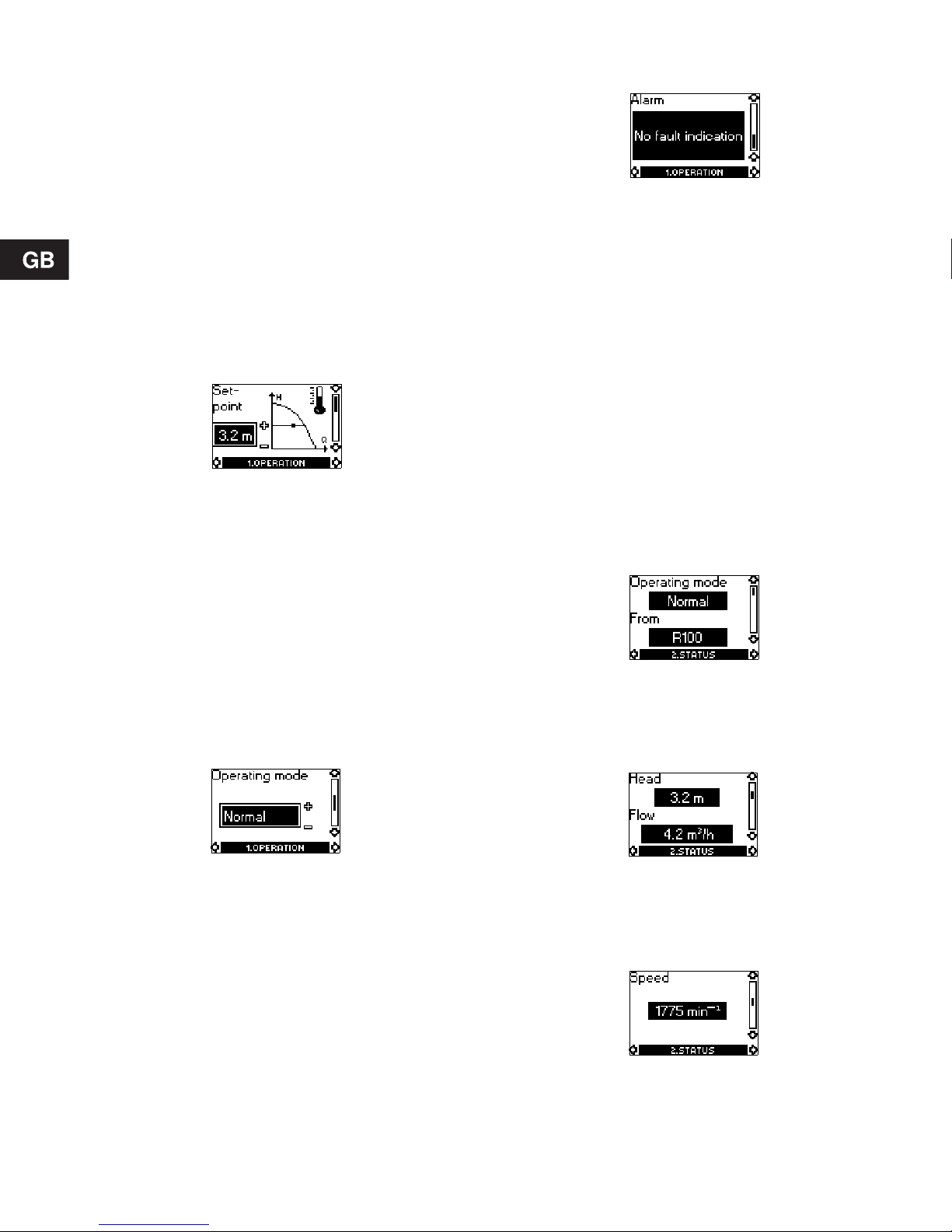
7.5.1 Setpoint
This display depends on the control mode selected
in the display “Control mode” in menu INSTALLATION.
If the pump is remote- or forced-controlled via external signals, the number of possible settings will be
reduced, see section 7.8 Priority of settings.
Attempts to change the settings will result in an indication in the display saying that the pump is remotecontrolled and changes therefore cannot be made.
The following example of display will appear i f the
pump is in constant pressure control mode.
In this display, the desired head is set.
Furthermore, it is possible to choose between the
following operating modes:
• Stop,
• Min. (min. curve),
• Max. (max. curve).
This display will be a little different in the case of pro-
portional pressure control or constant curve duty.
The actual duty point of the pump is indicated by a
square in the Q/H field. The pump cannot register
very low flow rates, and the square will therefore dis appear.
7.5.2 Operating mode
Select one of the following operating modes:
• Stop,
• Min. (min. curve),
• Normal (proportional pressure, constant pressure
or constant curve),
• Max. (max. curve).
7.5.3 Fault indications
If the pump is faulty, the cause will appear in this display.
Possible causes:
• Overtemperature
(UPE xx-40 and UPE xx-60),
• Pump blocked,
• Internal fault
(UPE xx-80).
The fault indication can be reset in this display. If the
fault cause has not disappeared when resetting is attempted, this will be indicated in the display.
7.6 Menu STATUS
The displays appearing in this menu are status displays only. It is not possible to change or set values.
The actual values in the display are stated as a
guide.
7.6.1 Operating mode
This display shows the actual operating mode (Stop,
Min., Normal or Max.) and where it was selected
(Pump, R100, BUS or External).
7.6.2 Head and flow
Very low flows cannot be registered, and the R100
will show “<” in front of the lowest possible value of
the pump in question.
7.6.3 Speed
The actual pump speed.
Page 21
21
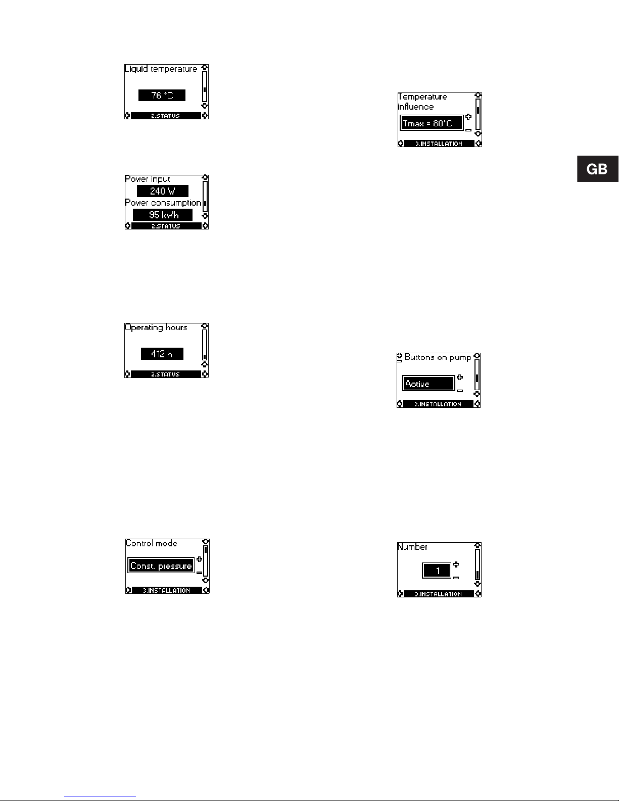
7.6.4 Liquid temperature
The actual temperature of the pumped liquid.
7.6.5 Power input and power consumption
Actual power input and power consumption of the
pump.
The value of power consumption is an accumulated
value and cannot be set to zero.
7.6.6 Operating hours
Operating hours of the pump.
The value of operating hours is an accumulated
value and cannot be set to zero.
7.7 Menu INSTALLATION
In this menu, the settings are chosen that should be
considered when installing the pump.
7.7.1 Control mode
Description of function, see section 6.1 Control
modes or section 6.4 Constant curve duty.
Select one of the following control modes:
• Prop. pressure (proportional pressure),
• Const. pressure (constant pressure),
• Const. curve (constant curve).
The desired setpoint or curve for the control mode is
set in 7.5.1 Setpoint in menu OPERATION.
7.7.2 Temperature influence
Description of function, see section 6.5 Temperature
influence.
The temperature influence function can be activated
in this display.
In the case of temperature influence, the pump must
be installed in the flow pipe. It is possible to choose
between maximum temperatures of 50°C and 80°C.
The temperature influence function will be active
only in proportional or constant pressure control
mode.
When the temperature influence is active, a small
thermometer is shown in the display “Setpoint” under
OPERATION, see section 7.5.1 Setpoint.
Note: If the pump is controlled via bus, temperature
influence cannot be set by means of the R100.
7.7.3 Buttons on pump
To prevent unauthorized persons from operating the
pump, the function of the buttons “+” and “–” can be
deactivated in this display. The buttons can be reactivated only by means of the R100.
The buttons can be set to:
• Active,
• Not active.
7.7.4 Pump number
A number between 1 and 64 can be allocated to a
pump or can be changed so that the R100 or Pump
Management System 2000 can distinguish between
two or more pumps.
The Pump Management System 2000 can, however,
only accept the numbers 1 to 8.
Page 22

22
7.8 Priority of settings
The forced-control signals will influence the settings
available on the pump and with the R100. By means
of the pump control panel or the R100, the pump can
always be set to max. curve duty or to stop.
If two or more functions are activated at the same
time, the pump will operate according to the function
with the highest priority.
The priority of the settings is as shown in the following table:
With fault signal module MC 40/60 or MC 80:
Example: If, via an external signal, the pump has
been forced to operate according to the max. curve,
the pump control panel and the R100 can only set
the pump to stop.
With bus module MB 40/60 or MB 80:
Example: If, via an external signal, the pump has
been forced to operate according to the max. curve,
the pump control panel, the R100 or the bus signal
can only set the pump to stop.
Priority
Possible settings
Pump control
panel or R100
External
signals
1 Stop
2Max. curve
3 Stop
4 Max. curve
5 Min. curve Min. curve
6 Setting of head
Setting of head
(0-10 V)
Pri-
ority
Possible settings
Pump control
panel or R100
External
signals
Bus
signal
1 Stop
2 Max. curve
3 Stop Stop
4
Max.
curve
Max.
curve
5
Min.
curve
Min.
curve
6
Setting of
head
Page 23
23
8. Fault finding char t
See also section 6.6 Indicator lights.
Note: The R100 can also be used for fault finding.
Before removing the terminal box cover, make sure that the electricity supply has been switched off
for at least 5 minutes. The voltage to a possible fault signal module must also have been switched
off.
The pumped liquid may be scalding hot and under high pressure. Before any removal or dismantling
of the pump, the system must therefore be drained or the isolating valves on either side of the pump
must be closed.
Fault Cause Remedy
The pump is not running.
A fuse in the installation is blown. Replace the fuse.
Current/voltage-operated earth-leakage cir-
cuit breaker has tripped out.
Cut in the circuit breaker.
Electricity supply failure (e.g. overvoltage or
undervoltage).
Check that the electricity supply falls
within the specified range.
The pump is defective. Replace the pump.
The pump is not running.
The green indicator
light is flashing.
The pump has been stopped in one of the
following ways:
1. With the button “–”.
2. With the R100.
3. External on/off switch in position off
(expansion module).*
4. Via bus signal (bus module).*
1. Start the pump by pressing “+”.
2. Start the pump with the R100 or
by pressing “+”.
3. Switch on the on/off switch.*
4. Start the pump via bus signal.*
* The fault can be temporarily corrected by selecting max. curve duty on the pump or
with the R100, as external forced-control signals will be ignored.
The pump has
stopped due to a fault.
The red indicator light
is on and the green indicator light is off.
The pump has stopped because of too high
ambient or liquid temperature.
Check that the ambient and liquid
temperatures fall within the specified
ranges.
Pump blocked and/or impurities in the pump. Remove the air vent screw and turn
the rotor by means of a screwdriver
inserted into the slot in the shaft end,
and/or dismantle and clean the pump.
Noise in the system.
The green indicator
light is on.
Air in the system. Vent the system.
The flow is too high. Reduce the head (setpoint) and pos-
sibly change over to constant pressure.
The pressure is too high. Reduce the head (setpoint) and pos-
sibly change over to proportional
pressure.
Noise in the pump.
The green indicator
light is on.
Air in the pump. Vent the pump.
The inlet pressure is too low. Increase the inlet pressure and/or
check air volume in the expansion
tank (if installed).
Insufficient heat in
some places in the
heating system.
The pump flow is too low. Increase the head (setpoint) and/or
change over to constant pressure.
Page 24
24
9. Megging
If an installation incorporating a UPE pump is to be
megged, the pump should be electrically separated
from the installation.
Megging of UPE pumps can be carried out as described below:
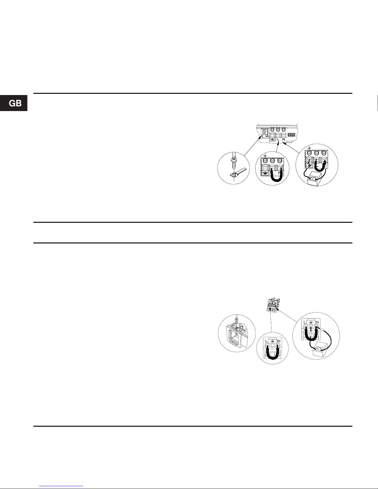
Megging of UPE 25-40, 25-40 A, 25 -60, 25-60 A, 32-40 and 32 -60
1. Switch off the electricity supply.
2. Remove the terminal box cover.
3. Remove the wires from terminals L and N, and the ea rth
wire (see A).
4. Remove the screw for electronics frame connection (s ee B).
5. Short-circuit terminals L and N using a short wire (s ee C).
6. Test between terminals L/N and ea rth (see D). Maxim um
test voltage: 1500 VAC/DC.
Note: Never test between supply t erminals ( L and N).
Maximum permissible leakage current: < 5 mA .
7. Remove the short wire between terminals L and N (se e C).
8. Fit the screw for electronics frame connection (see B).
9. Fit the supply wires to terminals L and N, and the earth wire
(see A).
10. Fit the terminal box cove r.
11. Switch on the electricity sup ply.
TM01 0653 1797
Megging of UPE 25-80, 32-80, 40-80 and 50-80
1. Switch off the electricity supply.
2. Remove the mains plug.
3. Remove the wires from terminals L and N, and the ea rth
wire (see page 294).
4. Short-circuit terminals L and N on the mains plug using a
short wire (see C).
5. Remove the terminal box cover.
6. Remove screw for electronics frame connection and l ift
frame connection to ensure a saf e vertica l clearanc e
(minimum 2 mm) (see B).
7. Fit the short-circuited mains plug.
8. Test between terminals L/N and ea rth (see D).
Maximum test voltage: 1500 VAC/DC.
Note: Never test between supply t erminals (L and N).
Maximum permissible leakage current: < 5 mA .
9. Fit the screw for electronics frame connection (see B).
10. Remove the short-cir cuited ma ins plug.
11. Fit the terminal box cover.
12. Remove the short wir e betwee n ter minals L and N (se e C).
13. Fit the wire to termi nals L and N, and the eart h wire
(see page 294).
14. Fit the mains p lug (see page 294 ).
15. Switch on the e lectricity supply.
TM01 0657 1897
A
C
D
B
N
L
N
L
A
B
C
D
Page 25

25
10. Technical data
Supply voltage
1 x 230-240 V –10%/+6%, 50 Hz, PE.
Motor protection
The pump requires no external motor protection.
Enclosure class
IP 42.
Insulation class
H.
Relative air humidity
Maximum 95%.
Ambient temperature
0°C to +40°C.
Temperature class
TF110 to CEN 335-2-51.
Liquid temperature
Maximum +110°C.
Continuously: +15°C to +95°C.
Pumps in domestic hot-water sy stems:
Continuously: +15°C to +60°C.
To avoid condensation in the terminal box and the
stator, the pumped liquid temperature must always
be higher than the ambient temperature. See the table below:
System pressure
Pipe connection:
• UPE 25-40, 25-40 A, 25-60, 25-60 A, 25-80,
32-40, 32-60 and 32-80: Maximum 10 bar.
Flange connection:
• UPE 32-80 F, 40-80 F and 50-80 F: PN 6
(maximum 6 bar) or PN 10 (maximum 10 bar).
• The system pressure is indicated on the pump
flanges.
Inlet pressure
The following minimum pressures must be available
at the pump inlet during operation:
EMC (electromagnetic compatibility)
EN 61 000-6-2.
EN 61 000-6-3.
Sound pressure level
The sound pressure level of the pump is lower than
43 dB(A).
Leakage current
The pump mains filter will cause a discharge current
to earth during operation. I
leakage
< 3.5 mA.
Inputs and outputs of expan sion modu les
Ambient
temperature
[°C]
Liquid temperature
Min. [°C] M ax. [°C]
15 15 110
20 20 110
25 25 110
30 30 110
35 35 90
40 40 70
Pump type
Liquid temperature
75°C 90°C 110°C
m head m head m head
UPE xx-40 0.5 2.8 11.0
UPE xx-60 0.5 2.8 11.0
UPE xx-80 0.5 2.8 11.0
Start/stop input
External potential-free switch.
Contact load: 5 V, 0.1 mA.
Screened cable.
Loop resistance:
Maximum 130 Ω/km.
Logical levels:
Logical zero: U < 1.5 V.
Logical one: U > 4.0 V.
Max. curve input
Min. curve input
Input for analog
0-10 V signal
External signal: 0-10 VDC.
Maximum load: 0.1 mA.
Screened cable.
Fault signal
module output
Internal potential-free changeover contact.
Maximum load: 250 V, 2 A AC1.
Minimum load: 5 V, 1 mA.
Screened cable.
Bus input
Grundfos GENIbus protocol,
RS-485.
Screened cable.
Lead cross section: 0.25 - 1 mm².
Cable length: Maximum 1200 m.
Page 26

26
11. Disposal
This product or parts of it must be di sposed of in an
environmentally sound way:
1. Use the public or private waste collection service.
2. If this is not possible, contact the nearest
Grundfos company or service workshop.
Subject to alterations.
Page 27

293
UPE 25-40 (A), UPE 25-60 (A), UPE 32-40 and UPE 32-60
9-12 mm
15-25 mm
2
TM01 1261 4097
TM01 1262 4097
TM01 1263 4097
6
4
TM01 1265 4097
3
5
1
TM01 1264 4097 TM01 1266 4097
Page 28

294
UPE 25-80, UPE 32-80, UPE 40-80 and UPE 50-80
2
TM01 0372 2197
TM01 0727 2197
TM01 0375 2197
1 Nm
9-12 mm
15-25 mm
TM01 0373 2197
TM01 0374 2197
6
4
TM01 0728 2197
3
5
1
Max. 1 Nm
Page 29

295
TM00 4472 3394
G
L1
B2
B1
B4
H3
H2
H1
Pump versions
Dimensions
L1 L2 L3 B1 B2 B3 B4 H1 H2 H3 G
UPE 25-40 A
180
236 290 85 72 88 92 49 112 80 1½
UPE 25-60 A
180
236 290 85 65 95 92 49 112 80 1½
Page 30

296
TM00 4473 3394
H1
H2
H3
L2
L3
B4
B1
B2
B3
L1
G
Pump versions
Dimensions
L1 L2 L3 B1 B2 B3 B4 H1 H2 H3 G
UPE 25-40
180
236 290 85 47 105 77 32 102 57 1½
UPE 25-40 B
180
236 290 85 47 105 77 32 102 57 1½
UPE 32-40
180
236 290 85 47 105 77 39 102 57 2
UPE 25-60
130
186 240 85 47 105 77 32 102 57 1½
UPE 25-60
180
236 290 85 47 105 77 32 102 57 1½
UPE 25-60 B
180
236 290 85 47 105 77 32 102 57 1½
UPE 25-80
180
236 290 106 51 117 85 32 130 54 1½
UPE 32-60
180
244 302 85 47 105 77 39 102 57 2
UPE 32-80
180
244 302 106 60 117 85 39 130 71 2
UPE 32-80 B
180
244 302 106 60 117 85 39 130 71 2
Page 31

297
TM01 0159 3398
L3
L2
H3
H2
H1
L1
B3
B1
B4
B2
D5
D4
D2
D1
D3
D3
Pump versions
Dimensions
L1 L2 L3 B1 B2 B3 B4 H1 H2 H3 D1 D2 D3 D4 D5
UPE 32-80 F
PN 6/PN 10
220 274 298 106 60 117 85 60 130 73 32 78
90/
100
140 14/19
UPE 32-80 FB
PN 6/PN 10
220 274 298 106 60 117 85 60 130 73 32 78
90/
100
140 14/19
UPE 40-80 F
PN 6/PN 10
250 328 304 97 65 116 95 65 130 79 42 88
100/
110
150 14/19
UPE 40-80 FB
PN 6/PN 10
250 328 304 97 65 116 95 65 130 79 42 88
100/
110
150 14/19
UPE 50-80 F
PN 6/PN 10
280 97 70 116 95 130 79 50 99
110/
125
150 14/19
Page 32

Denmark
GRUNDFOS DK A/S
Martin Bachs Vej 3
DK-8850 Bjerringbro
Tlf.: +45-87 50 50 50
Telefax: +45-87 50 51 51
E-mail: info_GDK@grundfos.com
www.grundfos.com/DK
Argentina
Bombas GRUNDFOS de Argentina S.A.
Ruta Panamericana km. 37.500 Lote
34A
1619 - Garin
Pcia. de Buenos Aires
Phone: +54-3327 414 444
Telefax: +54-3327 411 111
Australia
GRUNDFOS Pumps Pty. Ltd.
P.O. B ox 2040
Regency Park
South Australia 5942
Phone: +61-8-8461-4611
Telefax: +61-8-8340 0155
Austria
GRUNDFOS Pumpen Vertrieb
Ges.m.b.H.
Grundfosstraße 2
A-5082 Grödig/Salzburg
Tel.: +43-6246-883-0
Telefax: +43-6246-883-30
Belgium
N.V. GRUNDFOS Bellux S.A.
Boomsesteenweg 81-83
B-2630 Aartselaar
Tél.: +32-3-870 7300
Télécopie: +32-3-870 7301
Brazil
GRUNDFOS do Brasil Ltda.
Rua Tomazina 106
CEP 83325 - 040
Pinhais - PR
Phone: +55-41 668 3555
Telefax: +55-41 668 3554
Canada
GRUNDFOS Canada Inc.
2941 Brighton Road
Oakville, Ontario
L6H 6C9
Phone: +1-905 829 9533
Telefax: +1-905 829 9512
China
GRUNDFOS Pumps (Shanghai) Co. Ltd.
22 Floor, Xin Hua Lian Building
755-775 Huai Hai Rd, (M)
Shanghai 200020
PRC
Phone: +86-512-67 61 11 80
Telefax: +86-512-67 61 81 67
Czech Republic
GRUNDFOS s.r.o.
Cajkovského 21
779 00 Olomouc
Phone: +420-585-716 111
Telefax: +420-585-438 906
Finland
OY GRUNDFOS Pumput AB
Mestarintie 11
Piispankylä
FIN-01730 Vantaa (Helsinki)
Phone: +358-9 878 9150
Telefax: +358-9 878 91550
France
Pompes GRUNDFOS Dis t rib ution S.A.
Parc d’Activités de Chesnes
57, rue de Malacombe
F-38290 St. Quentin Fallavier (Lyon)
Tél.: +33-4 74 82 15 15
Télécopie: +33-4 74 94 10 51
Germany
GRUNDFOS GMBH
Schlüterstr. 33
40699 Erkrath
Tel.: +49-(0) 211 929 69-0
Telefax: +49-(0) 211 929 69-3799
e-mail: infoservice@grundfos.de
Service in Deutschland:
e-mail: kundendienst@grundfos.de
Greece
GRUNDFOS Hellas A.E.B.E.
20th km. Athinon-Markopoulou Av.
P.O. B ox 71
GR-19002 Peania
Phone: +0030-210-66 83 400
Telefax: +0030-210-66 46 273
Hong Kong
GRUNDFOS Pumps (Hong Kong) Ltd.
Unit 1, Ground floor
Siu Wai Industrial Centre
29-33 Wing Hong Street &
68 King Lam Street, Cheung Sha Wan
Kowloon
Phone: +852-27861706/27861741
Telefax: +852-27858664
Hungary
GRUNDFOS Hungária Kft.
Park u. 8
H-2045 Törökbálint,
Phone: +36-23 511 110
Telefax: +36-23 511 111
India
GRUNDFOS Pumps India Private Limited
Flat A, Ground Floor
61/62 Chamiers Aptmt
Chamiers Road
Chennai 600 028
Phone: +91-44 432 3487
Telefax: +91-44 432 3489
Indonesia
PT GRUNDFOS Pompa
Jl. Rawa Sumur III, Blok III/CC-1
Kawasan Industri, Pulogadung
Jakarta 13930
Phone: +62-21-460 6909
Telefax: +62-21-460 6910/460 6901
Ireland
GRUNDFOS (Ireland) Ltd.
Unit 34, Stillorgan Industrial Park
Blackrock
County Dublin
Phone: +353-1-2954926
Telefax: +353-1-2954739
Italy
GRUNDFOS Pompe Italia S.r.l.
Via Gran Sasso 4
I-20060 Truccazzano (Milano)
Tel.: +39-02-95838112
Telefax: +39-02-95309290/95838461
Japan
GRUNDFOS Pumps K.K.
1-2-3, Shin Miyakoda
Hamamatsu Cit y
Shizuoka pref. 431-21
Phone: +81-53-428 4760
Telefax: +81-53-484 1014
Korea
GRUNDFOS Pumps Korea Ltd.
6th Floor, Aju Building 679-5
Yeoksam-dong, Kangnam-ku, 135-916
Seoul Korea
Phone: +82-2-5317 600
Telefax: +82-2-5633 725
Malaysia
GRUNDFOS Pumps Sdn. Bhd.
7 Jalan Peguam U1/25
Glenmarie Industrial Park
40150 Shah Alam
Selangor
Phone: +60-3-5569 2922
Telefax: +60-3-5569 2866
Mexico
Bombas GRUNDFOS de Mexico S.A. de
C.V.
Boulevard TLC No. 15
Parque Industrial Stiva Aeropuerto
Apodaca, N.L. 66600
Mexico
Phone: +52-81-81 44 40 00
Telefax: +52-81-81 44 40 10
Netherlands
GRUNDFOS Nederland B.V.
Postbus 104
NL-1380 AC Weesp
Tel.: +31-294-492 211
Telefax: +31-294-492244/492299
New Zealand
GRUNDFOS Pumps NZ Ltd.
17 Beatrice Tinsley Crescent
North Harbour Industrial Estate
Albany, Auckland
Phone: +64-9-415 3240
Telefax: +64-9-415 3250
Norway
GRUNDFOS Pumper A/S
Strømsveien 344
Postboks 235, Leirdal
N-1011 Oslo
Tlf.: +47-22 90 47 00
Telefax: +47-22 32 21 50
Poland
GRUNDFOS Pompy Sp. z o.o.
ul. Klonowa 23
Baranowo k. Poznania
PL-62-081 Przezmierowo
Phone: +48-61-650 13 00
Telefax: +48-61-650 13 50
Portugal
Bombas GRUNDFOS Portugal, S.A.
Rua Calvet de Magalhães, 241
Apartado 1079
P-2770-153 Paço de Arcos
Tel.: +351-21-440 76 00
Telefax: +351-21-440 76 90
Russia
OOO GRUNDFOS
Shkolnaya 39
RUS-109544 Moscow
Phone: +7-095 564 88 00, +7-095 737
30 00
Telefax: +7-095 564 88 11, +7-095 737
75 36
e-mail: grundfos.moscow@grundfos.com
Singapore
GRUNDFOS (Singapore) Pte. Ltd.
24 Tuas West Road
Jurong Town
Singapore 638381
Phone: +65-6865 1222
Telefax: +65-6861 8402
Spain
Bombas GRUNDFOS España S.A.
Camino de la Fuentecilla, s/n
E-28110 Algete (Madrid)
Tel.: +34-91-848 8800
Telefax: +34-91-628 0465
Sweden
GRUNDFOS AB
Lunnagårdsgatan 6
431 90 Mölndal
Tel.: +46-0771-32 23 00
Telefax: +46-31 331 94 60
Switzerland
GRUNDFOS Pumpen AG
Bruggacherstrasse 10
CH-8117 Fällanden/ZH
Tel.: +41-1-806 8111
Telefax: +41-1-806 8115
Taiwan
GRUNDFOS Pumps (Taiwan) Ltd.
7 Floor, 219 Min-Chuan Road
Taichung, Taiwan, R.O.C.
Phone: +886-4-2305 0868
Telefax: +886-4-2305 0878
Thailand
GRUNDFOS (Thailand) Ltd.
947/168 Moo 12, Bangna-Trad Rd., K.M.
3,
Bangna, Phrakanong
Bangkok 10260
Phone: +66-2-744 1785 ... 91
Telefax: +66-2-744 1775 ... 6
Turkey
GRUNDFOS POMPA SAN. ve TIC. LTD.
STI
Bulgurlu Caddesi no. 32
TR-81190 Üsküdar Istanbul
Phone: +90 - 216-4280 306
Telefax: +90 - 216-3279 988
United Arab Emirates
GRUNDFOS Gulf Distribution
P.O. Box 16768
Jebel Ali Free Zone
Dubai
Phone: +971-4- 8815 166
Telefax: +971-4-8815 136
United Kingdom
GRUNDFOS Pumps Ltd.
Grovebury Road
Leighton Buzzard/Beds. LU7 8TL
Phone: +44-1525-850000
Telefax: +44-1525-850011
U.S.A.
GRUNDFOS Pumps Corporation
17100 West 118th Terrace
Olathe, Kansas 66061
Phone: +1-913-227-3400
Telefax: +1-913-227-3500
Addresses revised 12.05.2005
Page 33

www.grundfos.com
Being responsible is our foundation
Thinking ahead makes it possible
Innovation is the essence
96416899 0605
115
Repl. 96416899 0603
 Loading...