

Page 1
GRUNDFOS
INSTRUCTIONS
http://waterheatertimer.org/Water-heater-recirculation-system.html
Comfort System
Hot Water Recirculation System
US Installation and operating instructions
ANSI/NSF61 and
IAPMO listed
Page 2

Shipment Inspection page 1.
Pre-Installation Checklist page 1.
Pump Mounting page 2.
Electrical page 5.
Timer Control Technical Data and Application page 5.
Timer Operation page 6.
Warranty page 7.
CONGRATULATIONS! You are now the owner of a Grundfos Comfort System. It has
been carefully inspected and tested before shipment. It should give you long, efficient,
trouble-free service. For maximum performance and reliability, please follow the
simple instructions in this manual. NOTE: Please understand this is not an anti-scald
device. You may have some warm water in your cold water line under the sink where
the valve is installed. Once the cold water line is opened, the warm water will dissipate
in a very short time.
Shipment Inspection
Examine the components carefully to make sure no damage has occurred to the
pump during shipment. Care should be taken to ensure the pump is NOT dropped or
mishandled; dropping will damage the pump.
Grundfos Hot Water Package Includes:
• One Grundfos UP15 circulator with timer and linecord
• One Under Sink, Thermal By-Pass Valve
• Two Valve mounting screws
• Installation and Operating Instructions
Items that must be supplied by Installer:
• 2- 1/2” NPT X 3/8” compression flex hoses
• 2- 1/2” NPT X 1/2” NPT flex hoses
• Hand Tools
Pre-Installation Checklist
Before beginning installation procedures, the following checks should be made. They
are all important for proper installation of the circulator pump.
Maximum Water Temperature:
UP15 pump with line cord and timer only; The maximum allowable water temperature
is 150°F.
In a pressurized system, the required inlet pressure is the minimum allowable system
pressure.
page 1
Page 3
Pump Mounting: For Indoor Use
Note: Do not energize pump
until properly installed
1. Close the supply water valve to the water
heater located, in most cases, above the hot
water heater on the cold water inlet to the
hot water heater.
2. Drain the water from the hot water pipe
by opening a hot water faucet in the house.
Let the water run until it stops flowing.
Then drain remaining water from hot water
heater spigot. Leave the faucet open until
pump installation is complete. If water does
not stop flowing, check to make sure the
water to the hot water heater has been
completely shut off.
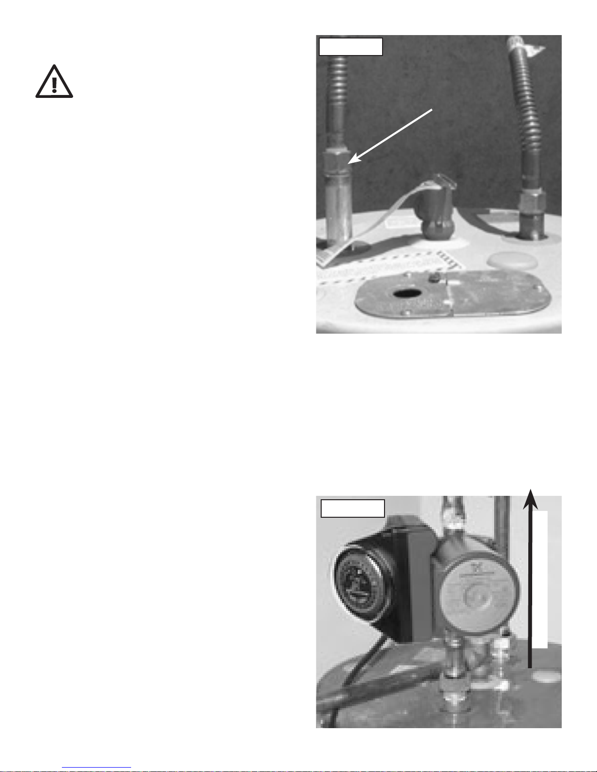
Picture 1
Disconnect
3. Disconnect the hot water heater at the hot water discharge. (see Picture #1)
4. Install pump onto the water heater discharge, using the 3/4” female fitting and
gasket supplied on the pump ensuring that the pump shaft is horizontal. The pump
should be installed so that the pump is pumping away from the hot water heater,
towards the house. Confirm the direction of pumping by observing the flow arrow on
the side of the pump housing. Be sure that the pump is not touching the exhaust vent
piping (chimney) of a gas or oil fired hot water heater. (See Picture #2)
5. Connect the hot water line to the 3/4”
Picture 2
NPT discharge of the pump. Use pipe
dope or Teflon tape to seal threads when
connecting to a 3/4 female NPT connection.
If a gasketed flexible copper water heater
connector is used pipe dope or Teflon tape is
not required
6. Reopen the supply valve to the hot water
heater and allow the water to run until all
the air has been purged from the piping.
Direction of water
7. Close faucet inside the house.
page 2
Page 4
8. Plug the line cord of pump into a 115V
outlet. Be sure to route the power cord
so that it does not touch the exhaust vent
piping of a gas or oil fired hot water heater.
9. Using the timer (see pg. 6), set the pump
to operate around your peak use times. (eg
30 minutes before the first shower until 15
minutes after last shower).
Valve Location
For the greatest effect, the valve should
be located at a faucet with the greatest
piping distance from the hot water heater.
If your home has a branched hot water line,
more than one valve may be necessary.
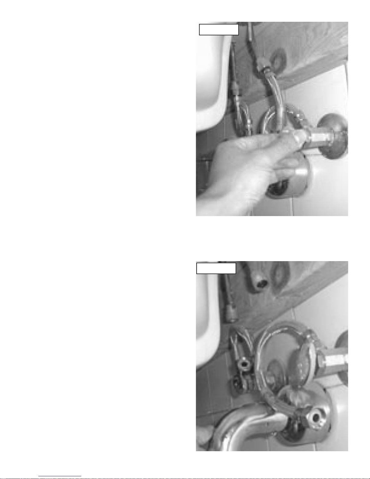
Picture 3
Valve Installation
Note: Do not use teflon tape or pipe dope on
the valve threads.
1. Close both the hot and cold water angle
stop valves below the sink. (see Picture #3)
2. Disconnect the risers. (see Picture #4)
3. Connect the 1/2”X1/2” flex hoses to the
ports on the valve marked “Hot Out” and
“Cold Out”. (see Picture #5)
4. Connect the 1/2”X3/8” flex hoses to the
ports on the valve marked “Hot In” and
“Cold In”. (see Picture #5)
Picture 4
Please note: By plumbing convention, the
hot water is on the left side and cold water
on the right, when looking at the sink. Your
piping may be different.
page 3
Page 5

5. Connect the 1/2” hose fitting from the “Hot Out” port to the left side of the faucet.
(see Picture #5)
6. Connect the 1/2” hose fitting from the “Cold Out” port to the right side of the faucet.
(see Picture #5)
7. Connect the 3/8” hose fitting from the “Hot In” port to the left angle stop valve. (see
Picture #5)
8. Connect the 3/8” hose fitting from the “Cold In” port to the right angle stop valve.
(see Picture #5)
9. Open both hot and cold water angle stop valves.
10. Valve may be mounted to the wall with supplied mounting screws if desired.
Valve Operation
If there is no hot water
at the faucet or there
appears to be too much
hot water on the cold
water side the following
steps will determine if
the valve is operating
correctly:
1. Close the cold water
angle stop valve below
the sink.
2. Open the cold water
faucet.
3. Water should slowly
flow from the faucet
until hot water reaches
the valve. The flow
should gradually decrease to a trickle of
water until no water is
coming from the faucet.
Picture 5
Hot Water
IN
Hot Water
OUT
Cold Water
OUT
Cold Water
IN
page 4
Page 6

Electrical
SAFETY WARNING
Warning - Risk of electrical shock - This pump is supplied with a grounding conductor.
To reduce the risk of electric shock, be certain that it is connected only to a properly
grounded grounding type receptacle. The safe operation of this pump requires that it
be grounded in accordance with the National Electrical Code and local governing codes
and regulations.
Electrical Requirements
The operating voltage and other electrical data are marked on the motor label. Make
sure that the motor is suitable for the electrical supply on which it will be used.
Electrical Connection
Insert the 115V plug on the line cord from the pump into a properly grounded 115V
outlet.
Timer Technical Data
TIMER CONTROL
Supply Voltage: 115-120 VAC, 60 hertz
Contact Rating: 16 amps
Ambient Temperature: -4°F to 175°F
Shortest Switching Interval: 15 minute increment
Switch Modes: “Timer”, “ON” Override, “OFF” Override
Protection: Clear plastic cover for dust and moisture protection of the clock face.
Timer Technical Application
The Grundfos timer control is designed only for use with specified Grundfos Series UP
circulators installed in indoor hot water service systems.
The timer control is designed to turn the circulator on and off at preset times, allowing
the user to select operation of the circulator during high use periods of the day.
page 5
Page 7

Timer Operation
Setting & Operating
The Timer Control
Starting the Pump
NOTE:
the system must be filled with liquid
and vented.
1. Set the timer switch to the actual time by turning the programming ring in the
direction of the arrow until the timing arrow points to the actual time on the ring.
2. Plug in the power cord from the circulator and set the manual switch to the “ON”
position. The circulator will now start.
3. Set the required “ON”/“OFF” times on the programming ring by pushing the
programming tabs either away from or toward the center of the ring. Tabs pushed
away from the center indicate the
circulator is switched “ON” while tabs
pushed toward the center indicate the
circulator is switched “OFF”.
4. Set the manual switch to the “TIMER”
position. The circulator will now start/
stop according to the settings of the
programming tabs.
Before the circulator is started,
5. For continuous operation, set the
manual switch to the “ON” position. To switch the circulator off, set the manual switch
to the “OFF” position. The “ON”/“OFF” modes may be used without affecting the
function of either the programming ring or the timer switch.
6. In case of power outage the timer will not keep time. After power has been restored,
the correct time of day must be reset by rotating the programming ring in the direction
of the arrow until the timing arrow points to the actual time on the ring.
page 6
Page 8

0.0 0.5 1.0 1.5 2.0 2.5 3.0 3.5 4.0 4.5 5.0 5.5 Q [US GPM]
0.0
0.5
1.0
1.5
2.0
2.5
3.0
3.5
4.0
4.5
5.0
[ft]
H
0.0 0.2 0.4 0.6 0.8 1.0 1.2 Q [m³/h]
0.0
0.2
0.4
0.6
0.8
1.0
1.2
1.4
[m]
H
UP15-10SU7P/TLC
60 Hz
http://waterheatertimer.org/Water-heater-recirculation-system.html
UP Series
5
Comfort System
The Comfort System uses a patented Comfort Valve®
and pump to provide instant availability of hot water at
the point of use.
Operation
The Comfort Valve® is installed at the fixture furthest
away from the hot-water tank. With a built-in timer, the
pump allows hot water to circulate along the loop
through the valve using the cold-water side as a return
line. As the temperature rises to 100 °F (38 ° C), the
valve closes directing hot water to the tap, thus
resulting in a constant availability of hot water.
Savings
The Comfort System saves up to 16,000 gallons
(60,566 liters) of water per year and per household
(based on average modern household usage) and
uses less energy than a 25 W light bulb.
Applications
• Domestic hot-water recirculation systems in singleand two-family houses.
Pumped liquids
• Domestic hot water
• Potable and non-potable water
Description
(UP open systems)
Inlet cone, bearing plate, bearing
retainers, rotor can, rotor
cladding, shaft retainer
Volute retainer (SU & SF models)
and stator housing
Shaft, upper and lower radial
bearings
Thrust bearing
Pump housing (volute)
O-ring and gaskets
Impeller PES composite (30 % glass-filled)
Terminal box Noryl® with EPDM gasket
Material
Stainless steel
Aluminium
Aluminium oxide ceramic
Carbon bearing and EPDM
retainer
Silicon bronze C875 or stainless
steel 300 series.
EPDM (ethylene propylene
rubber)
Grundfos Comfort Valve body materials
Description Trade name Material
Springs, pins, screens 300 Series Stainless steel
Valve body Ryton PPS
Thermal actuator
body
Check valve O-ring EPDM
Check valve body Acetal
Check valves plunger Thermoplastic
300 Series Stainless steel
Ambient and liquid temperatures
Liquid temperature: 36 °F (2 °C) to 150 °F (66 °C).
It is recommended to keep the operating temperature
as low as possible (e.g. 140 °F (60 °C)) to avoid
calcium precipitation.
Applications
Fig. 7 Comfort System
Motor
• Insulation class: F.
• Power consumption: 25 W.
• Voltage: 115 V.
• Current 0.23 A.
• Phase: 1.
The ambient temperature should always be lower than
the liquid temperature, as otherwise condensatio n may
form in the stator housing.
Maximum system pressure
145 psi (10 bar).
TM03 9126 3407
TM03 5547 3806
Fig. 8 Performance curve for the Comfort System
33
Page 9

Being responsible is our foundation
Thinking ahead makes it possible
Innovation is the essence
Limited Warranty
Products manufactured by GRUNDFOS PUMPS CORPORATION (GRUNDFOS) are warranted to
the original user only to be free of defects in material and workmanship for a period of 24 months
from date of installation, but not more than 30 months from date of manufacture. GRUNDFOS’
liability under this warranty shall be limited to repairing or replacing at GRUNDFOS’ option, without
charge, F.O.B. GRUNDFOS’ factory or authorized service station, any product of GRUNDFOS
manufacture. GRUNDFOS will not be liable for any costs of removal, installation, transportation,
or any other charges which may arise in connection with a warranty claim. Products which are sold
but not manufactured by GRUNDFOS are subject to the warranty provided by the manufacturer
of said products and not by GRUNDFOS’ warranty. GRUNDFOS will not be liable for damage or
wear to products caused by abnormal operating conditions, accident, abuse, misuse, unauthorized
alteration or repair, or if the product was not installed in accordance with GRUNDFOS’ printed
installation and operation instructions.
To obtain service under this warranty, the defective product must be returned to the distributor
or dealer of GRUNDFOS products from which it was purchased together with proof of purchase
and installation date, failure date, and supporting installation data. Unless otherwise provided,
the distributor or dealer will contact the GRUNDFOS factory or authorized service station for
instructions. Any defective product to be returned to the factory or service station must be sent
freight prepaid; documentation supporting the warranty claim and/or a Return Authorization must
be included if so instructed.
GRUNDFOS WILL NOT BE LIABLE FOR ANY INCIDENTAL OR CONSEQUENTIAL DAMAGES,
LOSSES, OR EXPENSES ARISING FROM INSTALLATION, USE, OR ANY OTHER CAUSES.
THERE ARE NO EXPRESS OR IMPLIED WARRANTIES, INCLUDING MERCHANTABILITY OR
FITNESS FOR A PARTICULAR PURPOSE, WHICH EXTEND BEYOND THOSE WARRANTIES
DESCRIBED OR REFERRED TO ABOVE.
Some jurisdictions do not allow the exclusion or limitation of incidental or consequential damages
and some jurisdictions do not allow limitations on how long implied warranties may last. Therefore,
the above limitations or exclusions may not apply to you. This warranty gives you specic legal
rights and you may also have other rights which vary from jurisdiction to jurisdiction.
LUPTL043 Rev. 10/05 (US)
Grundfos Pumps Corporation
17100 W. 118th Terrace
Olathe, Kansas 66061
Telephone: (913) 227-3400
Fax: (913) 227-3500
Grundfos Canada, Inc.
2941 Brighton Rd.
Oakville, Ontario L6H 6C9
Telephone: (905) 829-9533
Fax: (905) 829-9512
www.grundfos.com
Bombas Grundfos de Mexico, S.A. de C.V.
Boulevard TLC #15, Parque Industrial Stiva Aeropuerto
C.P. 66600 Apodaca, N.L. Mexico
Telephone: 52-81-8144-4000
Fax: 52-81-8144-4010
 Loading...