

Grundfos Unilift KP 150, Unilift KP 350, Unilift KP 250 Installation And Operating Instructions Manual
Page 1

Unilift KP 150, KP 250, KP 350
GRUNDFOS INSTRUCTIONS
Installation and operatin g instructi on s
DRAINAGE PUMP
1Z28
Page 2

LIMITED WARRANTY
Products manufactured by GRUNDFOS PUMPS CORPORATION (Grundfos) are
warranted to the original user only to be free of defects in material and workmanship
for a period of 24 months from date of installation, but not more than 30 months from
date of manufacture. Grundfos' liability under this warranty shall be limited to repairing or replacing at Grundfos' option, without charge, F.O.B. Grundfos' factory or
authorized service station, any product of Grundfos' manufacture. Grundfos will not
be liable for any costs of removal, installation, transportation, or any other charges
which may arise in connection with a warranty claim. Products which a re sold but
not manufactured by Grundfos are subject to the warranty provided by the manufacturer of said products and not by Grundfos' warranty. Grundfos will not be liable
for damage or wear to products caused by abnormal operating conditions, accident,
abuse, misuse, unauthorized alteration or repair, or if the product was not installed
in accordance with Grundfos' printed installation and operating instructions.
To obtain service under this warranty, the defective product must be returned to the
distributor or dealer of Grundfos' products from which it was pu rchased togeth er
with proof of purchase and installation date, failure date, and supporting installation
data. Unless otherwise provided, the distributor or dealer will contact Grundfos or
an authorized service station for instructions. Any defective product to be returned
to Grundfos or a service station must be sent freight prepaid; documentation supporting the warranty claim and/or a Return Material Authorization must be included
if so instructed.
GRUNDFOS WILL NOT BE LIABLE FOR ANY INCIDENTAL OR CONSEQUENTIAL DAMAGES, LOSSES, OR EXPENSES ARISING FROM INSTALLATION,
USE, OR ANY OTHER CAUSES. THERE ARE NO EXPRESS OR IMPLIED WARRANTIES, INCLUDING MERCHANTABILITY OR FITNESS FOR A PARTICULAR
PURPOSE, WHICH EXTEND BEYOND THOSE WARRANTIES DESCRIBED OR
REFERRED TO ABOVE.
Some jurisdictions do not allow the exclusion or limitation of incidental or consequential damages and some jurisdictions do not a llow limit actio ns on how long
implied warranties may last. Therefore, the above limitations or exclusions may not
apply to you. This warranty gives you specific legal rights and you may also have
other rights which vary from jurisdiction to jurisdiction.
2
Page 3

3
Unilift KP 150, KP 250, KP 350
Installation and operating instructions 4
Notice d’installation et d’entretien 9
Instrucciones de instalación y funcionamiento 15
Page 4

4
CONTENTS
Page
1. General description 4
1.1 Applications 4
1.2 Operating conditions 4
1.3 Sound pressure level 5
2. Electrical connection 5
3. Installation 5
3.1 Pipe connection 5
3.2 Basic requirements 5
3.3 Pump location and positioning 5
3.4 Adjustment of float switch 6
3.5 Non-return check valve 6
4. Operation 6
4.1 Starting 6
5. Maintenance 6
5.1 Cleaning the pump 6
5.2 Replacement of parts 7
6. Fault finding chart 8
7. Disposal 8
1. General description
Fig. 1
1. Discharge port 1.25" NPT.
2. Handle.
3. Clamp.
4. Suction strainer.
5. Outer casing.
6. Float switch (optional).
1.1 Applications
The Grundfos Unilift KP 150, KP 250 and KP 350
pumps are single-stage submersible pumps
designed for pumping grey water.
CAUTION: This pump has been evaluated for use
with water, grey wastewater and heated wastewater.
The pump is capable of pumping water which contains a limited quantity of spherical solids up to 3/8"
in diameter without being blocked or damaged.
The pump is suitable for automatic (with float switch)
as well as manual operation and can be installed in a
permanent installation or used as a portable pump.
The pump is suitable for:
• Drainage of basements or buildings prone to
flooding,
• Pumping of wastewater from washing machines,
sinks, baths, showers, etc., up to the sewer level,
• Dewatering of sites or the pumping of water for
fountains,
• Pumping in draining wells,
• Emptying swimming pools, ponds, tanks, or fountains.
The pump is not suitable for pumping:
• sewage
• liquids containing long fibers
• liquids containing solid particles larger than 3/8" in
diameter
• flammable liquids (oil, gasoline, etc.)
• aggressive liquids.
Note: If the pump has been used for very dirty or
chlorinated water it should be flushed thoroughly
with clean water after use.
The pump contains approx. 70 ml of non-poisonous
motor liquid that may pollute the pumped liquid if the
pump should leak.
1.2 Operating conditions
Liquid temperature
Minimum 32°F. The maximum liquid temperature
depends on the rated voltage of the pump, see the
table below.
Storage temperature
Not lower than –4°F.
Minimum water level
Water level must be above strainer inlet.
Maximum installation depth
30 feet below liquid level.
Prior to installation, read these installation
and operating instructions. Installation and
operation must comply with local regulations and accepted codes of good practice.
TM03 4327 2006
With float switch
Do not use the pump in or at swimming
pools, garden ponds, etc. when there are
persons in the water.
Voltage
Maximum
liquid temperature
1 x 115 V, 60 Hz +122°F (+113°F KP 350)
At intervals of at least 30 minutes, the pump is
allowed, however, to run at maximum +158°F for
periods not exceeding 2 minutes.
Page 5

5
1.3 Sound pressure level
The sound pressure level of the pump is lower than
the limiting values stated in the EC Council Directive
98/37/EC relating to machinery.
A-weighted sound pressure level
< 65 dB(A) in accordance with ISO 3743.
2. Electrical connection
The electrical connection should be carried out in
accordance with local regulations and following the
National Electrical Code. The pump should be
grounded. The operating voltage and frequency are
marked on the nameplate. Make sure that the motor
is suitable for the electricity supply on which it will be
used.
When connecting the pump for manual operation,
the 115V plug is inserted into a 115V outlet. If a float
switch is included for automatic operation it will be of
the "Piggy-back" design. Plug the 115V plug on the
float switch into the 115V outlet, and plug the 115V
plug from the pump into the float switch plug.
Fig. 2
3. Installation
3.1 Pipe connection
Steel or rigid plastic pipe can be screwed directly into
the 1.25" NPT discharge port. For permanent installation, it is recommended to fit a union, a non-return
valve and an isolating valve in the discharge pipe.
Other recommendations:
• For portable or temporary installations, plastic discharge pipe can be used in conjunction with a
suitable screwed/hose connector.
• Removal of the pump should be by a cable
secured to the pump handle and not by the discharge pipework.
• Screwed threads should be sealed using Teflon
®
tape.
Note: The pump must not be installed hanging from
the discharge pipe.
3.2 Basic requirements
When the pump is installed in a permanent installation with a float switch, and the cable length is set to
the minimum length of at least 2.5" inches, the minimum dimensions of the well should be as shown in
fig. 3.
Furthermore, the well should be sized according to
the relation between the water flow to the well and
the pump capacity.
Fig. 3
3.3 Pump location and positioning
Pumps without or with float switch can be used in
vertical position with the discharge port uppermost or
in horizontal or tilted position with the discharge port
as the highest point of the pump. See fig. 4.
When used in horizontal position, the pump must be
completely covered by liquid.
Fig. 4
When the pipe/hose has been connected, the pump
is ready for use.
Note: Do not lift the pump by means of the electric
cable. Lift the pump by means of a cable secured to
the handle of the pump.
The Unilift KP pumps have built-in thermal
overload protection and require no additional motor protection. If the motor is
overloaded, it will stop automatically.
When it has cooled to normal temperature
it will start automatically.
TM03 4461 2106
As a precaution, the pump must be connected to a socket with earth connection.
It is recommended to fit the permanent
installation with a ground fault circuit interrupter (GFCI) with a tripping current
<30mA.
115V outlet
Float switch plug
("Piggy-back")
Pump plug
TM03 4330 2006TM00 1548 0493
‹
‹
‹
‹
‹
‹
‹
‹
‹
‹
‹
‹
‹
‹
‹
‹
‹
‹
‹
‹
‹
‹
‹
‹
‹
‹
‹
‹
‹
‹
‹
‹
‹
‹
‹
‹
‹
‹
‹
‹
‹
‹
‹
‹
‹
‹
‹
‹
‹
‹
‹
‹
‹
‹
‹
‹
‹
‹
‹
‹
‹
‹
‹
‹
‹
‹
‹
‹
‹
‹
‹
‹
‹
‹
‹
‹
‹
‹
‹
‹
‹
‹
‹
‹
‹
‹
‹
‹
‹
‹‹‹‹‹‹‹‹‹‹‹‹
‹‹‹‹‹‹‹‹‹‹‹
‹‹‹‹‹‹‹‹‹‹
‹‹‹‹‹‹‹‹‹‹
‹‹‹‹‹‹‹‹‹
‹‹‹‹‹‹‹‹
‹‹‹‹‹‹‹‹‹
‹‹‹‹‹‹‹‹‹
‹‹‹‹‹‹‹‹
‹
‹
‹
‹
‹
‹
‹
‹
‹
‹
‹
‹
‹
‹
‹
‹
‹
‹
‹
‹
‹
‹
‹
‹
‹
‹
‹
‹
‹
‹
‹
‹
‹
‹
‹
‹
‹
‹
‹
‹
‹
‹
‹
‹
‹
‹
‹
‹
‹
‹
‹
‹
‹
‹
‹
‹
‹
‹
‹
‹
‹
‹
‹
‹
‹
‹
‹
‹
‹
‹‹
‹
‹
‹
‹
‹
‹
‹
‹
‹
‹
‹
‹
‹
‹
‹
‹
‹
‹
‹
‹
‹
‹
‹
‹
‹
‹
‹
‹
‹
‹
‹
‹
‹
‹
‹
‹
‹
‹
‹
‹
‹
‹
‹
‹
‹
‹
‹
‹
‹
‹
‹
‹
‹
‹
‹
‹
‹
‹
‹
‹
‹
‹
‹‹
‹
‹
‹
‹
‹
‹
‹
‹
‹
‹
‹
‹
‹
‹
‹
‹
‹
‹
‹
‹
‹
‹
‹
‹
‹
‹
‹
‹
‹
‹
‹
‹
‹
‹
‹
‹
‹‹‹
‹
‹
‹
‹
‹
‹
‹
‹
‹
‹
‹
‹‹
‹
‹
‹
‹
‹
‹
‹
‹
‹
‹
‹
‹
‹
‹
‹
‹
‹
‹
‹
‹
‹
‹
‹
‹
‹
‹
‹
‹
‹
‹
‹
‹
‹
‹
‹
‹
‹‹‹
‹
‹
‹
‹
‹
‹
‹
‹
‹
‹
‹
‹
‹
‹‹
‹
‹
‹
‹
‹
‹
‹
‹
‹
‹
‹
‹
‹
‹
‹
‹
‹
‹
‹
‹
‹
‹
‹
‹
‹
‹
‹
‹
‹
‹
‹
‹
‹
‹
‹
‹
‹‹‹
‹
‹
‹
‹
‹
‹
‹
‹
‹
‹
‹
‹
‹
‹
‹
‹
‹
‹
‹
‹
‹
‹
‹
‹
‹
‹
‹
‹
‹
‹
‹
‹
‹
‹
‹
‹
‹
‹
‹
‹
‹
‹
‹
‹
‹
‹
‹
‹
‹
‹
‹
‹
‹
‹
‹
‹
‹
‹
‹
‹
‹
‹
‹
‹
‹
‹
‹
‹
‹
‹
‹
‹
‹
‹
‹
‹
‹
‹
‹
‹
‹
‹
‹
‹
‹
‹
‹
‹
‹
‹
‹
‹
‹
‹
‹
‹
‹
‹
‹
‹
‹
‹
‹
‹
‹
‹
‹
‹
‹
‹
‹
‹
‹
‹
‹
‹
‹
‹
‹
‹
‹
‹
‹
‹
‹
‹
‹
‹
‹
‹
‹
‹
‹
‹
‹
‹
‹
‹
‹
‹
‹
‹
‹
‹
‹
‹
‹
‹
‹
‹
‹
‹
‹
‹
‹
‹
‹
‹
‹
‹
‹
‹
‹
‹
‹
‹
‹
‹
‹
‹
‹
‹
‹
‹
‹
‹
‹
‹
‹
‹
‹
‹
‹
‹
‹
‹
‹
‹
‹
‹
‹
‹
‹
‹
‹
‹
‹
‹
‹
‹
‹
‹
‹
‹
‹
‹
‹
‹
‹
‹
‹
‹
‹
‹
‹
‹
‹
‹
‹
‹
‹
‹
‹
‹
‹
‹
‹
‹
‹
‹
‹
‹
‹
‹
‹
‹
‹
‹
‹
‹
‹
‹
‹
‹
‹
‹
‹
‹
‹
‹
‹
‹
‹
‹
‹
‹
‹
‹
‹
‹
‹
‹
‹
‹
‹
‹
‹
‹
‹
ø 350 mm
400 mm
16 inches
With float switch
14 inches
Page 6

6
Before positioning the pump, make sure that the suction strainer will not be blocked or partly blocked by
silt, mud or similar materials.
This can be avoided by positioning the pump on
bricks, an iron plate, etc. See fig. 5.
Fig. 5
3.4 Adjustment of float switch
The float switch can automatically turn the pump on
and off. Switching the adjustment is possible by
repositioning the float switch in the handle of the
pump.
The free cable length must always be:
• at least 2.5 inches
• no more than 6 inches.
Fig. 6
The start/stop level varies according to the cable
length.
For manual operation, unplug both the pump and
float switch from the 115V outlet. Plug the 115V plug
on the pump into the outlet.
3.5 Non-return check valve
Whenever the pump is installed in a permanent
installation with a float switch, a non return valve
must be fitted in the discharge pipe or hose.
4. Operation
4.1 Starting
Before starting the pump, check:
• whether the pump is submerged in liquid. During
normal operation, the strainer of the pump must
be below the surface of the liquid
• whether the pump is positioned on a base so that
the strainer is not blocked by silt, mud or similar
materials
• whether the pipe/hose connection is tight
• whether the discharge pipe is open (bend of hose,
etc.)
• whether the pump is connected to the electric supply in accordance with the instructions
• check the float switch for free movement.
After start-up, chec k th at:
• the pump operates properly, that water is being
pumped, and the pump operates through the control sequence
• the float switch will allow the pump to pump down
to a level of approximately 4". To pump out below
this level secure the switch in the manual position.
See 3.4 Adjustment of float switch.
5. Maintenance
Under normal operating conditions, the pump is
maintenance-free.
If the pump has been used for liquids other than
clean water, it should be flushed through with clean
water immediately after use.
5.1 Cleaning the pump
If the pump does not deliver a sufficient quantity of
water because of sediment, dismantle and clean the
pump.
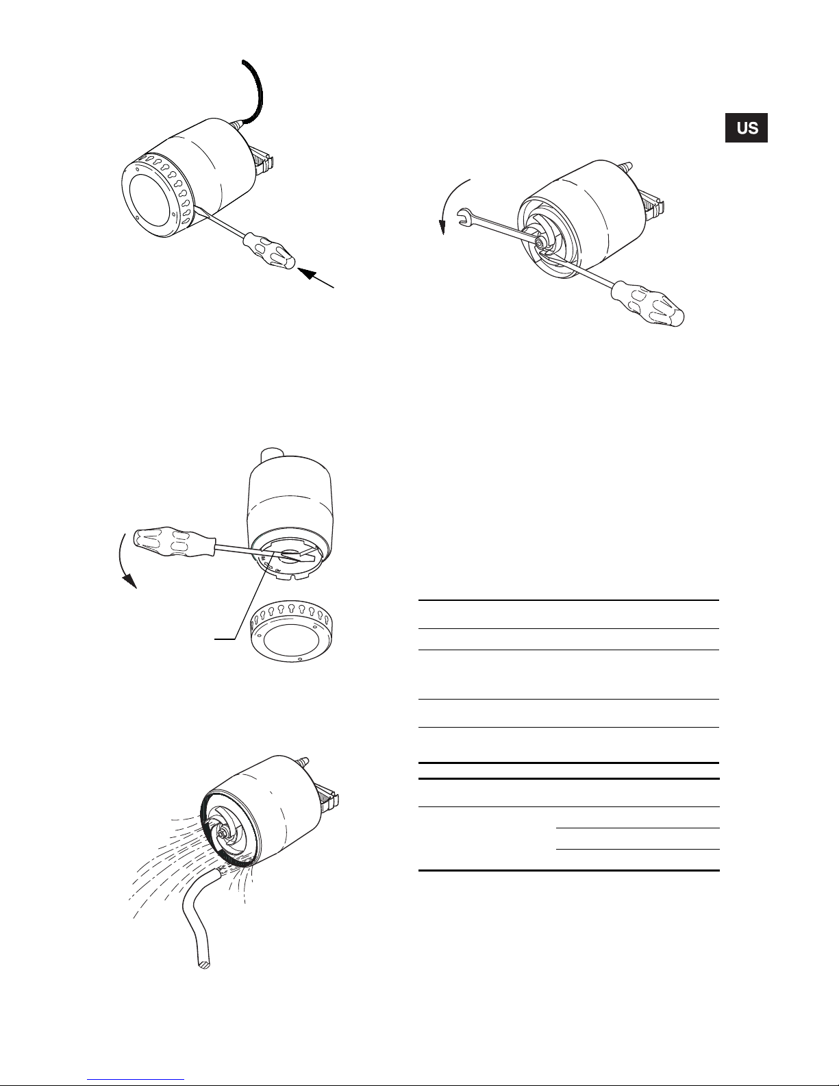
The dismantling of the pump is carried out as follows:
1. Disconnect the electricity supply.
2. Allow the pump to drain.
3. Carefully loosen the suction strainer by inserting
a screwdriver in the recess between the outer
casing and the strainer and pressing it hard.
Repeat the procedure until the strainer is free
and can be removed, see fig. 7.
TM00 1549 0493TM03 4331 2006
Cable length
Min. 2.5"
Cable length
Max. 6"
Start Stop Start Stop
Unilift KP 150
Unilift KP 250
11.5" 5.5" 12,5" 3.5"
Unilift KP 350 12" 6" 13 4"
‹‹‹‹‹‹‹‹
‹‹‹‹‹‹‹
‹‹‹‹‹‹
‹‹‹‹‹‹
‹‹‹‹‹‹
‹‹‹‹‹
‹‹‹‹‹
‹‹‹‹‹
‹
‹
‹
‹
‹
‹
‹
‹
‹
‹
‹
‹
‹
‹
‹
‹
‹
‹
‹
‹
‹
‹
‹
‹
‹
‹
‹
‹
‹
‹
‹
‹
‹
‹
‹
‹
‹
‹
‹
‹
‹
‹
‹
‹
‹
‹
‹
‹
‹
‹
‹
‹
‹
‹
‹
‹
‹
‹
‹
‹
‹
‹
‹
‹
‹
‹
‹
‹
‹
‹
‹
‹
‹
‹
‹‹
‹
‹
‹
‹
‹
‹
‹
‹
‹
‹
‹
‹
‹
‹
‹
‹
‹
‹
‹
‹
‹
‹
‹
‹
‹
‹
‹
‹
‹
‹
‹
‹
‹
‹
‹
‹
‹
‹
‹
‹
‹
‹
‹
‹
‹
‹
‹
‹
‹
‹
‹
‹
‹
‹
‹
‹
‹
‹
‹
‹
‹
‹
‹
‹
‹
‹
‹
‹
‹
‹
‹
‹
‹
‹
‹
‹
‹
‹
‹
‹
‹
‹
‹
‹
‹
‹
‹
‹
‹
‹
‹
‹
‹
‹
‹
‹
‹
‹
‹
‹
‹
‹
‹
‹
‹‹
‹
‹
‹
‹
‹
‹
‹
‹
‹
‹
‹
‹
‹
‹
‹
‹
‹
‹
‹
‹
‹
‹
‹
‹
‹
‹
‹
‹
‹
‹
‹
‹
‹
‹
‹
‹
‹‹‹
‹
‹
‹
‹
‹
‹
‹
‹
‹
‹
‹
‹‹
‹
‹
‹
‹
‹
‹
‹
‹
‹
‹
‹
‹
‹
‹
‹
‹
‹
‹
‹
‹
‹
‹
‹
‹
‹
‹
‹
‹
‹
‹
‹
‹
‹
‹
‹
‹
‹
‹‹‹
‹
‹
‹
‹
‹
‹
‹
‹
‹
‹
‹
‹
‹
‹
‹
‹
‹
‹
‹
‹
‹
‹
‹
‹
‹
‹
‹
‹
‹
‹
‹
‹
‹
‹
‹
‹
‹
‹
‹
‹
‹
‹
‹
‹
‹
‹
‹
‹
‹
‹
‹
‹
‹
‹
‹
‹
‹
‹
‹
‹
‹
‹
‹
‹
‹
‹
‹
‹
‹
‹
‹
‹
‹
‹
‹
‹
‹
‹
‹
‹
‹
‹
‹
‹
‹
‹
‹
‹
‹
‹
‹
‹
‹
‹
‹
‹
‹
‹
‹
‹
‹
‹
‹
‹
‹
‹
‹
‹
‹
‹
‹
‹
‹
‹
‹
‹
‹
‹
‹
‹
‹
‹
‹
‹
‹
‹
‹
‹
‹
‹
‹
‹
‹
‹
‹
‹
‹
‹
‹
‹
‹
‹
‹
‹
‹
‹
‹
‹
‹
‹
‹
‹
‹
‹
‹
‹
‹
‹
‹
‹
‹
‹
‹
‹
‹
‹
‹
‹
‹
‹
‹
‹
‹
‹
‹
‹
‹
‹
‹
‹
‹
‹‹
‹
‹
‹
‹
‹
‹
‹
‹‹
‹
‹
‹
‹
‹
‹
‹
‹
‹
‹
‹
‹‹‹
‹
‹
‹
‹
‹
‹
‹
‹
‹
‹
‹
‹
‹
‹
‹
‹
‹
‹
‹
‹
‹
‹
‹
‹
‹
‹
‹
‹
‹
‹
‹
‹
‹
‹
‹
‹
‹
‹
‹
‹
‹
‹
‹
‹
‹
‹
‹
‹
‹
‹
‹
‹
‹
‹
‹
‹
‹
‹
‹
‹
‹
‹
‹
‹
‹
‹
‹
‹
‹
‹
‹
‹
‹
‹
‹
‹‹
‹
‹
‹
‹
‹
‹
‹
‹
‹
‹
‹
‹
‹
‹
‹
‹
‹
‹
‹
‹
‹
‹
‹
‹
‹
‹
‹
‹
‹
‹
‹
‹
‹
‹
‹
‹
‹
‹
‹
‹
‹
‹
‹
‹
‹
‹
‹
‹
‹
‹
‹
‹
‹
‹
‹
‹
‹
‹
‹
‹
‹
‹
‹
‹
‹
‹
‹
‹
‹
‹
‹
‹
‹
‹
‹
‹
‹
‹
‹
‹
‹
‹
‹
‹
‹
‹
‹
‹
‹
‹
‹
‹
••••••••••••••
••••••••••••
•••••••••••
••••••••••••
•••••••••••
••••••••••
•••••••••••
••••••••••
••••••••••
••••••••••
•••••••••
••••••••
••••••••
Min./max.
cable length
Start
Stop
As a precaution, the suction strainer must
always be fitted to the pump during operation.
Never dismantle the pump unless the electricity supply has been switched off.
During dismantling, caution should be
exercised as there will be access to sharp
edges, etc. which may cut.
Page 7
7
Fig. 7
4. Clean the suction strainer and refit it.
If the pump still does not deliver a sufficient quantity
of water, dismantle the pump as follows:
1. Disconnect the electricity supply.
2. Turn the pump housing 90° counter-clockwise
using a screwdriver, see the arrow on the pump
housing. Pull off the housing, see fig. 8.
Fig. 8
3. Clean and flush the pump with water to remove
possible impurities between the motor and the
outer casing. Clean the impeller, see fig. 9.
Fig. 9
4. Check that the impeller can rotate freely. If not,
remove the impeller:
• Slacken and remove the nut on the motor shaft
(13 mm). Prevent the impeller from rotating by
means of a screwdriver, see fig. 10.
• Clean the impeller and around the shaft.
Fig. 10
5. Check the impeller, the pump housing and the
sealing part. Replace possible defective parts.
6. Assemble the pump in reverse order of dismantling.
Note: Check before and when fitting the pump housing that the sealing part is positioned correctly, see
fig. 11. Moisten the sealing part with water to facilitate the fitting.
5.2 Replacement of parts
The impeller assembly and electric cord can be
replaced.
The part numbers and the components included in
the service kits will appear from the tables below and
fig. 11.
If pump components other than those mentioned
above are damaged or defective, please contact
your pump supplier.
TM03 4329 2006TM03 1168 1205TM03 1169 1205
Pump housing
TM03 1170 1205
Pump type Part number
Impeller kit
KP 150, 60 Hz
KP 250, 60 Hz
KP 350, 60 Hz
015783
015784
015786
Replacement cords
10' 60HZ
25' 60HZ
016728
016729
Service kit Description Qty.
Impeller kit
Impeller 1
Nut 1
Gasket 1
Page 8

8
Fig. 11
6. Fault finding chart
7. Disposal
This product or parts of it must be disposed of in an
environmentally sound way:
Use the public or private waste collection service.
TM03 4328 2006
Impeller
Nut
Gasket
Pump housing
Strainer
Electrical cord
Fault Cause
1. Motor does not start. a) Supply failure.
b) Pump switched off by float switch/vertical level switch.
c) Fuses are blown.
d) Thermal relay has cut out the electricity supply to the motor
(see 2. Electrical connection).
e) Check cable for defects.
2. Thermal relay trips out
after short time of
operation.
a) Temperature of pumped liquid higher than that stated in 1.2 Operating con-
ditions.
b) Pump partly blocked by impurities (see 4. Operation).
c) Pump mechanically blocked (see 4. Operation).
d) Check volts and amperage.
e) Check cable for defects.
3. Pump runs but gives
insufficient water.
a) Pump partly blocked by impurities (see 4. Operation).
b) Discharge pipe/hose partly blocked. Check the non-return valve, if fitted.
c) Check the impeller, the pump housing and the sealing part (see
4. Operation).
4. Pump runs but gives no
water.
a) Pump blocked by impurities (see 4. Operation).
b) Non-return valve, if fitted, in discharge pipe/hose blocked in closed position.
c) Liquid level is too low. During normal operation, the liquid level must be
above the strainer.
d) Pumps with float switch: The free cable of the float switch is too long
(see 3.4 Adjustment of float switch).
Subject to alterations.
Page 9

21
Page 10

22
Page 11

U.S.A.
GRUNDFOS Pumps Corporation
17100 West 118th Terrace
Olathe, Kansas 66061
Phone: +1-913-227-3400
Telefax: +1-913-227-3500
Canada
GRUNDFOS Canada Inc.
2941 Brighton Road
Oakville, Ontario
L6H 6C9
Phone: +1-905 829 9533
Telefax: +1-905 829 9512
Mexico
Bombas GRUNDFOS de Mexico
S.A. de C.V.
Boulevard TLC No. 15
Parque Industrial Stiva
Aeropuerto
Apodaca, N.L.C.P. 66600
Phone: +52-81-8144 4000
Telefax: +52-81-8144 4010
Addresses revised 22.09.2005
Page 12

www.grundfos.com
Being responsible is our foundation
Thinking ahead makes it possible
Innovation is the essence
L-KP-TL-002 1/07
US
 Loading...