

Grundfos Unilift CC 5 M1, Unilift CC 7 M1, Unilift CC 9 M1, Unilift CC 7 A1, Unilift CC 5 A1 Service Instructions Manual
...Page 1

Service instructions
Unilift CC
1 / 8
96581224 0406
GB
8
Contents
1. Identification .................................................................................................................................... 2
1.1 Nameplate ......................................................................................................................................... 2
1.2 Type key............................................................................................................................................ 2
2. Fault finding............................................................................. .... ... ... ... ... .... ... ... ... ........................... 3
3. Cleaning the pump .......................................................................................................................... 4
3.1 Cleaning the suction strainer............................................................................................................. 4
3.2 Cleaning the impeller......................................................................................................................... 4
4. Dismantling and assembly ............................................................................................................. 5
4.1 Removing the motor .......................................................................................................................... 5
4.2 Replacing the capacitor ..................................................................................................................... 5
4.3 Replacing the impeller....................................................................................................................... 5
4.4 Replacing the supply cable or float switch......................................................................................... 6
4.5 Fitting the motor................................................................................................................................. 6
5. Winding resistances....................................................................... ... ... ........................................... 7
6. Drawing............................................................................................................................................. 8
Page 2
2 / 8
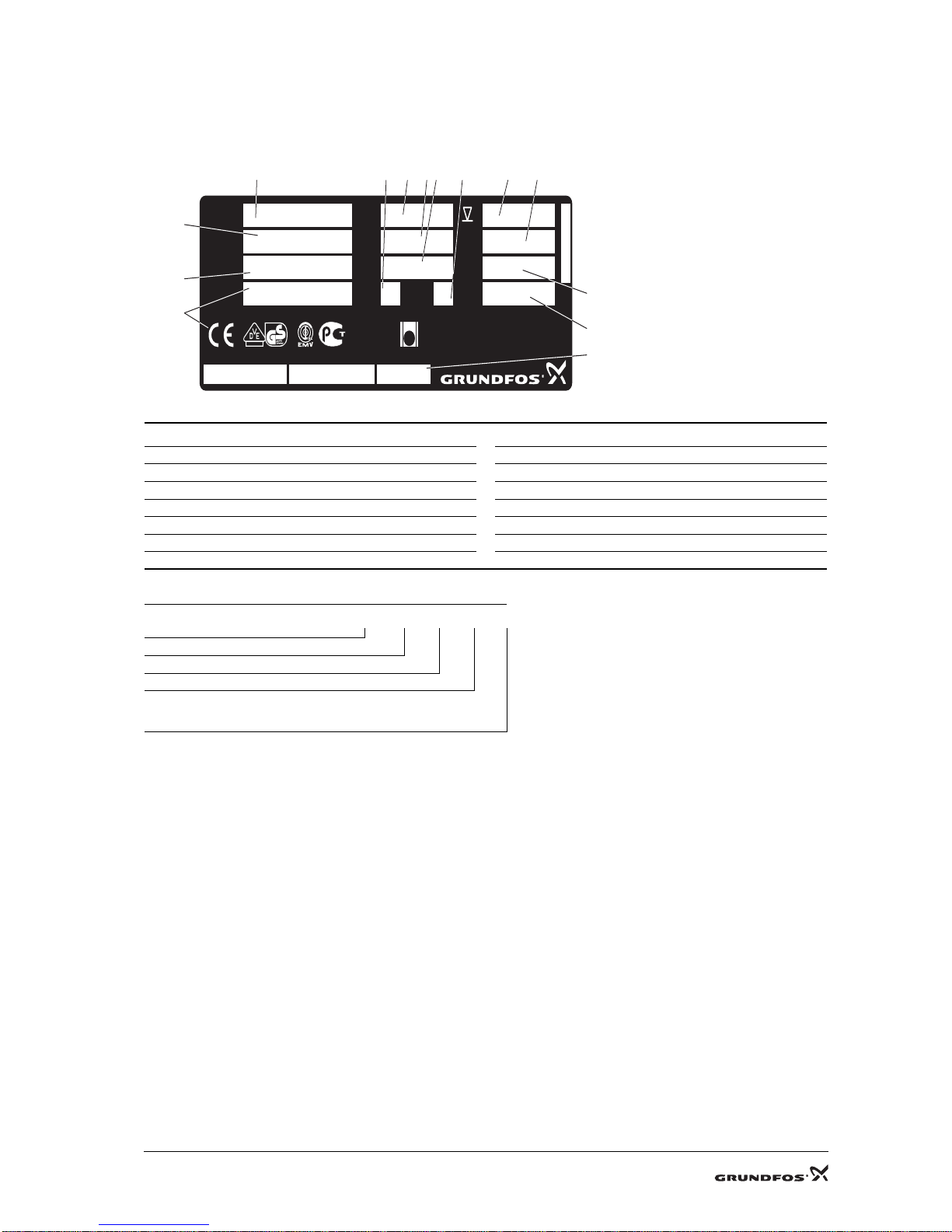
1. Identification
1.1 Nameplate
1.2 Type key
TM03 1001 0905
Pos. Description Pos. Description
1 Pump type 8 Maximum flow rate
2 Frequency 9 Motor insulation class
3 Maximum head 10 Enclosure class
4 Maximum liquid temperature during continuous operation 11 Approvals
5 Product number 12 Motor input power
6 Production code 13 Maximum installation depth
7 Full-load current 14 Supply voltage
Example Unilift CC 7 A1
Pump range
Type
Maximum head [m]
Operation
A1 = Automatic
M1 = Manual
1
3
5
14
11
8
7
13
12
10
T ype
1 x 220 - 240
V~
40 °C
m
9
IP
PC 0540
P171XXXX
Class
I
1/1
3,7 A
Model
P
1
780 W
14
3
f 50 Hz
Unilift CC9 - A1
96280970
H
max
Q
max
m/h
10 m
T
max
U
DIN EN12050-2
LGA
68
SN XXXXXXX
Made in Italy
PC 0540
F
A
R
56
2
9
4
6
Page 3
3 / 8
2. Fault finding
Switch off the electricity supply before dismantling the pump.
Fault Cause Remedy
1. Pump does not
run.
a) Electricity supply switched off. Switch on the electricity supply.
b) Fuses in installation blown. Replace defective fuses.
c) The pump thermal switch has tripped out. The thermal switch restarts the pump when the motor has
cooled to normal temperature.
d) The main winding is defective, see 5. Winding resist-
ances.
Replace the motor, see 4.1 Removing the motor.
2. The pump does
not run, but hums.
a) The capacitor is defective. Replace the capacitor, see 4.2 Replacing the capacitor.
Replace the motor, 4.1 Removing the motor.
b) The auxiliary winding is defective.
3. The pump stops
after short time of
operation (thermal switch tripped
out).
a) The pumped liquid temperature is too high. The pump restarts automatically after sufficient cooling.
b) Pump partly blocked by impurities or blocked. Clean the pump, see 3.2 Cleaning the impeller.
c) Water level too low when the pump is started. The
pump cannot self-prime.
Move the pump to a position with higher water level or add
water until the pump starts sucking.
4. Pump runs but
gives insufficient
water.
a) Pump is partly blocked by impurities. Clean the pump, see 3.2 Cleaning the impeller.
b) Discharge pipe/hose partly blocked by impurities. The
hose may be sharply bent.
Check and clean the non-return valve, if fitted.
c) Impeller, bottom part or diaphragm defective. Replace defective parts.
5. Pump runs but
gives no water.
a) Pump is blocked by impurities. Clean the pump, see 3.2 Cleaning the impeller.
b) Non-return valve in discharge pipe/hose blocked in
closed position or blocked by impurities. The hose may
be sharply bent.
Check the non-return valve. Clean or replace the valve, if
necessary.
c) Pumps with float sw itch:
The pump does not stop because the free cable length
of the float switch is too long.
Reduce the free cable length.
Page 4

4 / 8
3. Cleaning the pump
3.1 Cleaning the suction strainer
1. Drain the pump.
2. Loosen the strainer (pos. 84) by inserting a screwdriver between the bottom part (pos. 50) and the suction strainer
and turning the screwdriver.
Fig. 1. Removing the suction strainer
3. Clean and refit the suction strainer.
3.2 Cleaning the impeller
1. Loosen the strainer (pos. 84) by inserting a screwdriver between the bottom part (pos. 50) and the suction strainer
and turning the screwdriver.
2. Remove the screws (pos. 84b) and the bottom part (pos. 50).
Fig. 2. Removing the bottom part
3. Remove and clean the O-ring (pos. 37a) and the diaphragm (pos. 58).
4. Flush the inside of the pump between the motor and pump sleeve, and clean the impeller. Check that the impeller
(pos. 49) can rotate freely and is intact.
5. Fit the diaphragm, O-ring and bottom part.
6. Fit and tighten the screws.
7. Press the suction strainer onto the pump.
Switch off the electricity supply before dismantling the pump.
TM03 0831 0505
TM03 1112 1005
Page 5

5 / 8
4. Dismantling and assembly
General information
Position numbers of pump part (figures) refer to exploded views, sectional drawings and parts lists.
Before dismantling
• Disconnect the electricity supply to the motor.
• Remove the electric cable in accord ance with local regulations.
Before assembly
O-rings should always be replaced when the pump is overhauled.
• Clean and check all parts.
• Order the necessary service kits.
Replace defective parts by new parts.
Disposal
This product or parts of it must be disposed of in an environmentally sound way:
1. Use the public or private waste collection service.
2. If this is not possible, contact the nearest Grundfos company or service workshop.
4.1 Removing the motor
1. Loosen the strainer (pos. 84) by inserting a screwdriver between the bottom part (pos. 50) and the suction strainer
and turning the screwdriver.
2. Remove the screws (pos. 84b) and the bottom part (pos. 50).
Fig. 3. Removing the bottom part
3. Remove the O-ring (pos. 37a) and the diaphragm (pos. 58).
4. Remove the screws (pos. 36).
5. Remove the pump sleeve (pos. 55a) by holding the sleeve and pressing the impeller.
6. Moisten the O-rings (pos. 37 and 48a) and remove them.
7. Pull the motor (pos. 48) out of motor sleeve (pos. 55).
4.2 Replacing the capacitor
1. Remove the motor, see 4.1 Removing the motor.
2. Pull the capacitor (pos. 161) out of the retainer (pos. 160).
3. Pull of the cable terminals and fit the new capacitor.
4. Fit the motor, see 4.5
Fitting the motor.
4.3 Replacing the impeller
1. Remove the motor, see 4.1 Removing the motor.
2. Remove the retainer (pos. 160) with capacitor so that the shaft end is visible.
3. Insert a screwdriver into the slot in the shaft end and remove the impeller (pos. 49), nut (pos. 67) and washer (pos.
66) as well as the V-ring (pos. 159) in CC7 and CC9.
4. Keep the screwdriver in the slot and fit the washer, V-ring, if any, the new impeller and the nut.
5. Make sure that the nut is positioned in the "seat" of the impeller.
6. Fit the retainer (pos. 160) with capacitor.
7. Fit the motor, see 4.5
Fitting the motor.
TM03 1112 1005
Page 6

6 / 8
4.4 Replacing the supply cable or float switch
1. Remove the motor, see 4.1 Removing the motor.
2. Cut the defective cable and the cable entry just above the motor sleeve (pos. 55).
3. Cut off the wire connectors.
4. Pull the cable and cable relief (pos. 250a) out of the motor sleeve from the inside.
5. Push the cable entry out of the motor sleeve (pos. 55) from outside and in.
6. Lead the cable through the motor sleeve, and moisten the cable entry with water and fit it with the thin end
upwards. The cable entry must be approx. 20 cm from the cable end.
Note: The cable entry for H05 cable is red, that for H07 white.
7. Fit the cable relief (pos. 250a) and pull the cable entry into position in the motor sleeve. The cable entry must now
be fixed in the retainer in the motor sleeve. It must not be possible to pull the cable any longer. The cable entry is
fitted correctly when its collar is free of the motor sleeve.
8. Strip the cable and fit the conductors with new wire connectors, see Fig. 4.
Wiring diagram.
9. Fit the motor, see 4.5
Fitting the motor.
4.5 Fitting the motor
1. Fit the O-ring (pos. 48a) on the motor and place the motor in the motor sleeve (pos. 55).
2. Fit the O-ring (pos. 37) on the pump sleeve (pos. 55a).
3. Fit the pump sleeve on the motor sleeve.
4. Fit and tighten the three screws (pos. 36).
5. Fit the diaphragm (pos. 58).
6. Fit the O-ring (pos. 37) on the bottom part (pos. 50).
7. Fit the bottom part to the pump sleeve.
8. Fit and tighten the three screws (pos. 84b).
9. Fit the strainer (pos. 84).
Page 7

7 / 8
5. Winding resistances
By measuring on the mains plug the resistance in the mains winding and the cable is measured.
The float switch must point upwards during the measurement.
Fig. 4. Wiring diagram
Pump type
Winding resistance
a
±10%
a. The table values do not include the cable.
Resistance in cable: 2 x 10 m, approx. 1 Ω
Auxiliary winding Main winding
Unilift CC 5 99 Ω 43 Ω
Unilift CC 7 43 Ω 31 Ω
Unilift CC 9 31 Ω 11 Ω
TM03 1381 1905
1~
Red
White
Black
Red
Yellow/green
Float switch
Supply
Blue
Blue
Brown
Brown
Page 8

8 / 8
6. Drawing
TM03 1101 1005
 Loading...