

Grundfos SSP 2.0 B, SSP 3.0 B, STP 1.0 B, STP 1.5 B, STP 2.0 B Installation And Operating Instructions Manual
...Page 1
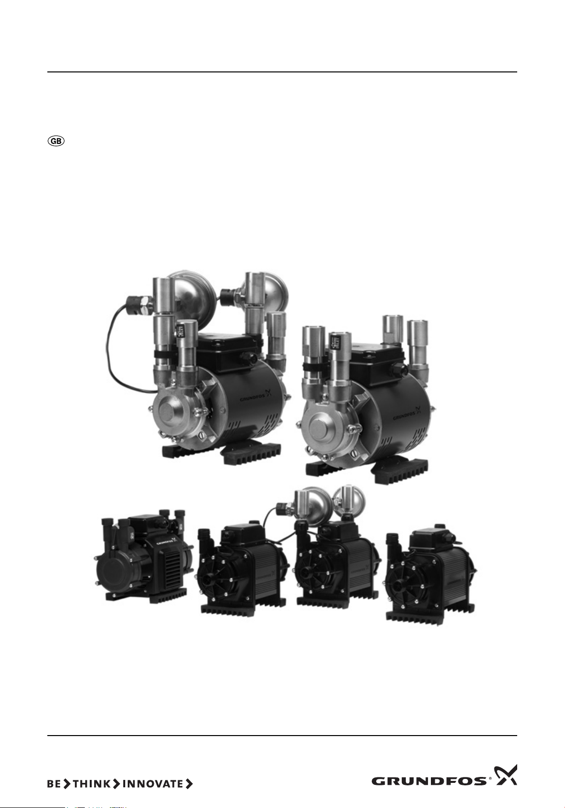
Shower pumps
Installation and operating instructions
GRUNDFOS INSTRUCTIONS
Page 2
Declaration of Conformity
We, Grundfos, declare under our sole responsibility that the products
SSL, STL, STC, SSR, STR, SSP, STP, SSN and STN, to which this
declaration relates, are in conformity with these Council directives on the
approximation of the laws of the EC member states:
— Machinery Directive (2006/42/EC).
Standards used: EN 809: 1998 and EN 60204-1: 2006.
— Low Voltage Directive (2006/95/EC).
Standards used: EN 60335-1: 2002 and EN 60335-2-41: 2003.
— EMC Directive (2004/108/EC).
Bjerringbro, 9th March 2010
Svend Aage Kaae
Technical Director
Grundfos Holding A/S
Poul Due Jensens Vej 7
8850 Bjerringbro, Denmark
Person authorised to compile technical file and
empowered to sign the EC declaration.
2
Page 3
Original installation and operating instructions.
Caution
Note
Note
1. Symbols used in this document
CONTENTS
1. Symbols used in this document
2. General description
2.1 Type key
3. Installation
3.1 Important instructions
3.2 Positioning the pump
3.3 Hot-water cylinder connections
3.4 Cold-water supply
3.5 Connecting the pump
3.6 STC, STR, SSR, STL and SSL pumps
3.7 Recommended installation
4. Electrical connections
4.1 Electrical connection, 1 x 230 V, 50 Hz
4.2 Electrical connection, low-voltage pumps (STL, SSL
and STL 2.0 CN)
5. Before using the pump
6. Negative-head pumps
6.1 General description
6.2 Dry-running protection
6.3 Connecting the pump
6.4 Installation instructions
6.5 Pressure and flow control
6.6 Operating instructions
6.7 Maintenance
7. Fault finding
7.1 Fault finding, negative-head pumps (STN, SSN and
STL 2.0 CN)
8. Technical data
9. Service
10. Disposal
Warning
Prior to installation, read these installation and
operating instructions. Installation and operation
must comply with local regulations and accepted
codes of good practice.
Warning
The use of this product requires experience with
and knowledge of the product.
Persons with reduced physical, sensory or
mental capabilities must not use this product,
unless they are under supervision or have been
instructed in the use of the product by a person
responsible for their safety.
Children must not use or play with this product.
Page
10
10
10
10
10
10
10
10
11
12
13
15
15
Warning
If these safety instructions are not observed,
3
3
3
4
4
4
5
5
2. General description
5
5
These installation and operating instructions apply to the
6
Grundfos Shower Pumps, types STL, SSL, STC, STR, SSR, STP,
9
SSP, STN and SSN.
9
For supplementary instructions regarding negative-head pumps,
see section 6. Negative-head pumps.
9
Your shower pump has been designed, manufactured and
9
carefully tested in England.
A shower pump installation requires a cold-water storage tank
and a hot-water cylinder. See fig. 2.
Low-voltage shower pumps
All transformers are fitted with auto-resetting thermal cut-outs.
If the transformer overheats for any reason, the thermal cut-out
will switch the pump off. The cut-out will automatically switch the
pump on again when the transformer has cooled down.
For the STL 2.0 CN pumps, also read the instructions in section
6. Negative-head pumps.
it may result in personal injury!
If these safety instructions are not observed,
it may result in malfunction or damage to the
equipment!
Notes or instructions that make the job easier
and ensure safe operation.
Please dispose of any packaging supplied with
this pump in an environmentally friendly and
legal manner.
2.1 Type key
Example S T P 2.0 B
S: Shower pump range
T: Twin impeller
S: Single impeller
P: Positive head
N: Negative head
L: Low voltage
C: Centrifugal
R: Regenerative
Maximum head [bar]
Material:
B: Brass
C: Composite
CN: Composite, negative head
3
Page 4
3. Installation
Caution
Note
Note
Caution
Caution
Note
3.2 Positioning the pump
3.1 Important instructions
Do not connect the pump directly to the water
mains supply.
The pump cannot be used with combination
boilers.
Make sure that no foreign particles (such as
solder and dust) are allowed to enter the pump.
The pump cannot operate if the level of the water
in the cold-water storage tank is below the level
of the pump.
• An inlet head of at least 2 metres is recommended.
• Non-return valves
Do not fit non-return valves in the suction line to the pump.
Make sure that the pump can vent back to the supply tank.
• STC, STR, SSR, STL and SSL pumps
The strainers supplied with the pump must be used on suction
connections. See fig. 1.
• Push-fit connections (SSN, SSP, STN and STP pumps)
The pump suction and discharge ports are fitted with push-fit
connections. The flexible hoses supplied with the pump must
be used.
Make sure that each hose connection is fully inserted to a
minimum depth of 33 mm.
• Disconnecting hose
To disconnect the "push-fit" hose, firmly push down the white
or grey retaining ring while pulling out the hose.
• Hot-water supply
The hot-water supply to the pump suction port should be
connected from the first outlet from the hot-water cylinder
expansion pipe, i.e. use a Surrey flange. An Essex flange is
recommended for STP 3.0 B, SSP 3.0 B, STP 4.0 B,
STN 3.0 B, SSN 3.0 B and STN 4.0 B pumps.
• No solder flux
Do not allow any solder flux to come into contact with any of
the plastic parts of the pump.
• Do not let the pump run dry
Purge with water thoroughly for 5 minutes before running the
pump.
• Test the system
Complete all pipework before making any electrical
connections. Do not allow any water to enter into the electrical
terminal box. After completing installation, the whole system
must be thoroughly tested, operating both hot and cold water
at maximum flow.
Maximum hot-water temperature setting must not exceed
60 °C (140 °F) in accordance with BS 6700: 2006.
Finally check that each connection is watertight and not
leaking.
Select a position for installing the pump which
affords easy access for subsequent servicing
and maintenance.
Minimum inlet head: 2 metres is recommended.
Keep the pump as close as possible to the source of hot and cold
water.
For optimum performance, ensure the following:
• A good water flow to the pump.
• Sufficient head.
• Unrestrictive pipework, 22 mm is recommended.
• Provision to prevent air locks.
Place the pump in a well-ventilated location, e.g. on the floor of
the airing cupboard.
Do not cover the pump, otherwise the motor will
overheat.
The pump must be placed in a frost-free location.
The pump must be mounted horizontally with the discharge ports
vertically upwards to ensure correct operation of the flow
switches.
To reduce noise, we recommend the pump be mounted on a
small concrete foundation of approximately 225 x 225 mm and
40-50 mm thick.
Connect the pump and shower system as shown in fig. 2.
To achieve 0.5 l/min. to turn the flow switches on, there must be
a minimum height between the cold-water storage tank and the
highest point of the pump outlet pipework of approximately
250 mm. See fig. 2.
The pump must be installed in accordance with the Water Supply
(Water Fittings) Regulations 1999.
For installation within a bathroom, locate the pump in accordance
with the IEE Wiring Regulations seventeenth edition
(BS 7671: 2008) Part 6, Section 601, for a shower pump with an
IPX2 enclosure. The pump must be positioned at least 0.6 metres
horizontally or 3 metres vertically away from any bath, shower
tray or basin.
Warning
The pump may be fitted under a bath, providing
this space is only accessible through the use of
a tool. If in doubt, consult the Wiring Regulations.
3.2.1 Negative head
If the water level in the cold-water storage tank is below the level
of the shower outlet, this is called a negative-head system. To
enable the pump to operate, a negative-head pump must be
used. See section 2.1 Type key.
If the pump is positioned above the outlet of
the hot-water cylinder, ensure that the pipework
to the pump from the cylinder has a downward
loop. This will help prevent air locks.
4
Page 5

3.3 Hot-water cylinder connections
Caution
Caution
Caution
Note
Note
Discharge
Suction
Plain hose
washer
Wire dome
Do not use any jointing compounds.
The use of a Surrey flange (see fig. 2) is recommended to ensure
a free-flowing supply of air-free hot water. An Essex flange is
recommended for STP 3.0 B, SSP 3.0 B, STP 4.0 B, STN 3.0 B,
SSN 3.0 B and STN 4.0 B pumps.
It is not recommended that the hot-water supply is taken directly
from the top of the hot-water cylinder, as entrapped air may cause
problems.
22 mm pipe should be used to ensure an adequate flow to the
pump. Where high flows are expected, 28 mm is recommended.
3.4 Cold-water supply
Do not connect the pump directly to the water
mains supply.
Do not use any jointing compounds or tape.
The cold-water supply to the pump must be connected using
22 mm pipe to the cold-water storage tank. See fig. 2. The tank
connector should be positioned at least 25 mm (1") lower than the
cold-water supply to the hot-water cylinder to prevent the supply
of hot water only.
3.5 Connecting the pump
Do not use any jointing compounds or tape.
For ease of installation, subsequent servicing and cleaning of
strainers, full-bore isolating gate valves must be fitted in the
pump suction and discharge ports.
Isolating valves greatly assist draining down,
strainer cleaning and refilling, which will result in
much lower service costs.
The flexible hoses supplied with the pump must be used for
connecting the pump to the pipework. Use of these hoses will
ensure strain- and vibration-free watertight connections. The
maximum bend angle should not exceed 45 °.
After initial installation, run the pump for a few minutes, switch off,
drain down and clean the suction strainers.
For SSN, SSP, STN and STP pumps, remove the suction hose
from the pump, and the strainer basket can be removed by hand
or with long-nosed pliers.
Line up the pipework, and fit hoses to the pump before
connecting to pipes. Position pipework accurately so that the
pump is not subject to mechanical strain.
Plastic nuts should be finger-tight plus 1/4 turn. The nuts should
be retightened after hot water has been pumped for the first time.
3.6 STC, STR, SSR, STL and SSL pumps
The strainers supplied with the pump must be fitted to the pump
suction connections. See fig. 1.
• Fit the plain hose washer to the discharge connection.
• Fit the strainer to the suction connection with the wire dome
towards pump.
TM04 6989 1310
Fig. 1 Fitting the strainer
Do not bend hoses as this will cause restriction
of flow.
5
Page 6
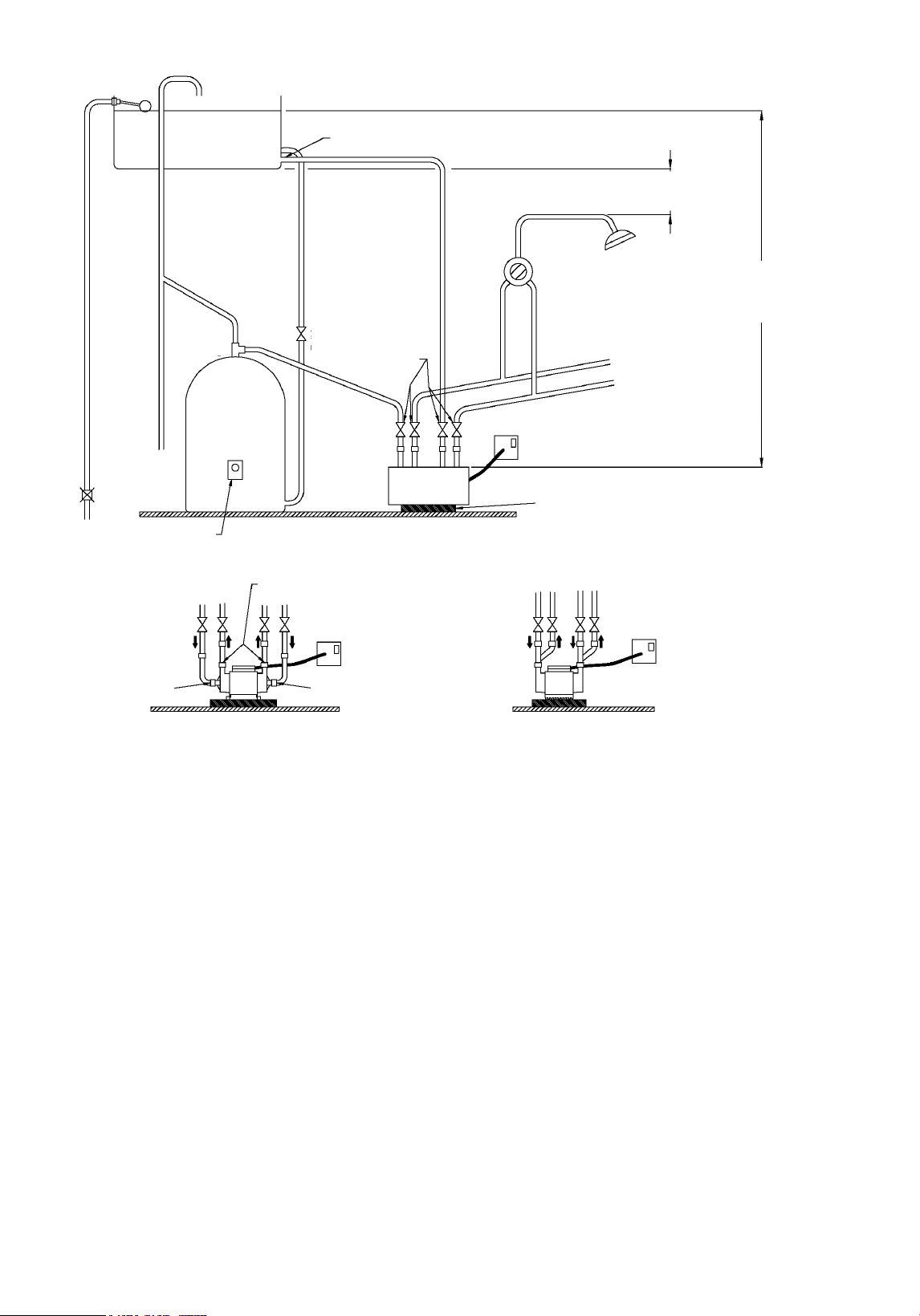
3.7 Recommended installation
System vent
Cold-water
storage tank of at
least 50 gallons
Cold-water supply connection to pump at least 25 mm
below cold-water supply connection to cylinder to
prevent supply of hot water only
Highest point of pipework at least 250 mm
(10 inches) below cold-water tank
See section 8. Technical data
for minimum and maximum
inlet heads from water level to
pump suction port.
Supply to another
shower, if required
Hot
Cold
Shower
valve
230 V, switched
spur
Low-voltage pumps
must be connected via
transformer only.
Mount the pump on
concrete slab to reduce
noise.
Recommended location of pump
at base of hot-water cylinder
Hot-water cylinder set
to a maximum of 60 ºC
Pipework connections, STC, STL
and SSL pumps
Pipework connections, STR, SSR, STP
and SSP pumps
Pump
Hot-water
cylinder
Domestic
hot-water
supply
Outlets
Flow
direction
Inlet
Inlet
Flow
direction
Inlet
Water mains supply
Expansion pipe
Cold-water supply to pump
Cold-water supply to
cylinder, min. 22 mm,
28 mm is recommended
22 mm
service
gate valves
Full-bore gate valve
Hot-water
supply to
pump
Surrey
flange
Outlet
Outlet
Inlet
Fig. 2 Positive-head pumps
Positive-head pumps
• Either Surrey, York, Warix or Essex flanges can be used,
depending on the cylinder type and installation.
• An Essex flange is recommended for pumps rated 3 bar and
above, i.e. models STP 3.0 B, SSP 3.0 B and STP 4.0 B.
• The hot-water supply to the shower pump must be via a
dedicated supply from the flange.
• Do not fit non-return valves on the inlet pipework to the pump.
The pump must be able to vent back to the cold-water storage
tank and hot-water cylinder.
• Avoid positioning outlets in the cold-water storage tank directly
below the inlet from the water mains supply in order to prevent
air from being drawn into the pump or hot-water cylinder.
• 22 mm pipework should be used to and from the pump.
• 15 mm pipework can only be used on STC 1.5 C, STL 1.0 C,
STL 1.5 C, SSL 1.4 C, STR 1.2 C, STR 1.5 C and SSR 1.5 C
pumps.
• The expansion pipe from the hot-water cylinder should always
rise in order to prevent trapped air.
• The outlet pipework from the pump to the shower valve should
rise, where possible, to prevent trapped air.
• Pipework from the pump to the shower valve should go up and
over, rather than under floor.
• Avoid blanked-off pipes (dead legs) which can trap air and
cause problems.
• Avoid kinks in the flexible hoses as this will restrict the flow of
water to and from the pump.
• All pipework should be secured down to minimise noise and
vibration.
• Low-voltage pumps, models STL 1.0 C, STL 1.5 C, SSL 1.4 C
and STL 2.0 C, must be connected to the 230 V electricity
supply via the supplied transformer only.
• After commissioning, the pump ensures that all hose
connections are tight to prevent air from being drawn into the
system.
TM04 6986 1310
6
Page 7

Fig. 3 Pump above hot-water cylinder outlet
Cold-water supply
to cylinder
Expansion pipe and
domestic hot-water supply
Hot-water supply
to pump
Anti-gravity loop
Hot-water cylinder thermostat set to
a maximum of 60 ºC
Hot-water
cylinder
Supply to shower
Hot
Cold
Surrey
flange
Low-voltage pumps must be
connected via transformer only.
Pump
Cold-water supply
to pump
22 mm service
gate valves
It is recommended that the pump is positioned at the base of the
hot-water cylinder.
If the pump is positioned above the outlet of the hot-water
cylinder, ensure that the pipework to the pump has an anti-gravity
or downward loop. This will help prevent air locks.
The inlet head from the water level in the cold-water storage tank
to the pump suction port must be within the minimum and
maximum values. See section 8. Technical data.
TM04 6987 1310
7
Page 8

Cold-water
storage tank of at
least 50 gallons
Supply to another
shower, if required
Hot
Cold
Shower
valve
Domestic
hot-water
supply
Bath
Basin
Cistern
Cold-water supply connection to
pump at least 25 mm below coldwater supply connection to cylinder
to prevent supply of hot water only
Mount the pump on concrete slab to
reduce noise.
System
vent
230 V,
switched
spur
Low-voltage pumps
must be connected
via transformer only.
See section 8. Technical data for
minimum and maximum inlet
heads from water level to pump
suction port.
Max. 8 m (26 ft)
Negative head
Positive head
Pipework connections, STN and SSN pumps
Flow
direction
Outlet
Inlet
Inlet
Pipework connections, STL 2.0 pumps
Hot-water
cylinder
Recommended location of pump
at base of hot-water cylinder
Hot-water cylinder set
to a maximum of 60 ºC
Water mains supply
Flow
direction
Outlets
Inlet
Inlet
230 V,
switched
spur
Low-voltage
transformer
Cold-water supply to
cylinder, min. 22 mm,
28 mm recommended
Full-bore gate valve
Surrey
flange
Pump
22 mm
service
gate valves
Cold-water supply to
pump, min. 22 mm
Hot-water
supply to
pump, min.
22 mm
Expansion pipe
Outlet
Fig. 4 Negative-head pumps, STN, SSN and STL 2.0 CN
Negative-head pumps
• Either Surrey, York, Warix or Essex flanges can be used,
depending on the cylinder type and installation.
• An Essex flange is recommended for pumps rated 3 bar and
above, i.e. models STN 3.0 B, SSN 3.0 B and STN 4.0 B.
• The hot-water supply to the shower pump must be via a
dedicated supply from the flange.
• Do not fit non-return valves on the inlet pipework to the pump.
The pump must be able to vent back to the cold-water storage
tank and hot-water cylinder.
• Avoid positioning outlets in the cold-water storage tank directly
below the inlet from the water mains supply in order to prevent
air from being drawn into the pump or hot-water cylinder.
• 22 mm pipework should be used to and from the pump.
• Connect the side of the pump with the larger expansion tank to
cold water and the side of the pump with the smaller
expansion tank to hot water.
• The expansion pipe from the hot-water cylinder should always
rise in order to prevent trapped air.
• The outlet pipework from the pump to the shower valve should
rise, where possible, to prevent trapped air.
8
• Pipework from the pump to the shower valve should go up and
over, rather than under floor.
• Avoid blanked-off pipes (dead legs) which can trap air and
cause problems.
• Avoid kinks in the flexible hoses as this will restrict the flow of
water to and from the pump.
• All pipework should be secured down to minimise noise and
• Low-voltage pumps, model STL 2.0 CN, must be connected to
• After commissioning, the pump ensures that all hose
vibration.
the 230 V electricity supply via the supplied transformer only.
connections are tight to prevent air from being drawn into the
system.
TM04 6989 1310
Page 9

4. Electrical connections
Caution
Caution
Warning
The pump must be earthed.
The pump must be connected to an external
mains switch with a contact separation gap
of at least 3 mm in each pole.
The pump must be connected to a 230 V, 50 Hz,
supply with a switched spur fused at 5 A
(10 A on models STP 4.0 B and STN 4.0 B).
Metal pipes must be earthed by the use of
earthing clamps to BS 951 and 4 mm earthing
wire.
Complete all pipework before making any
electrical connections.
Do not allow any water to enter into the electrical
terminal box.
If in doubt, consult a qualified electrician or call your local
electricity board engineer.
4.1 Electrical connection, 1 x 230 V, 50 Hz
Observe colour coding as follows:
• Brown to terminal L.
• Yellow/green to terminal E (PE).
Ensure that the earth lead is at least as long as the other two
leads.
• Blue to terminal N (neutral).
Insert the lead fully into the terminal connector and tighten the
screw firmly. Ensure that the connection is secure. Be sure to
tighten the cable restraint.
Ensure compliance with IEE Regulations. In the interests of
safety, it is recommended that a residual current device (RCD)
be installed in the supply circuit.
Warning
Do not operate the pump without the terminal box
cover in place.
The pump switch should be left "on" at all times for normal
operation of the system.
4.2 Electrical connection, low-voltage pumps
(STL, SSL and STL 2.0 CN)
Observe colour coding as follows:
• Brown to terminal L.
• Blue to terminal N.
For normal operation of the shower, the transformer can be left
permanently switched on. Very little power is used when the
pump is not running.
Copper pipes should have supplementary earth bonding. Where
the earth continuity has been broken, the pump suction and
discharge pipework should be connected with earthing clamps to
BS 951 and 4 mm earthing wire.
5. Before using the pump
Warning
Do not let the pump run dry.
Purge water thoroughly through the system
before switching on the electricity supply to
the pump.
Do not switch on the electricity supply.
1. Turn on the water supply. Allow the system to fill.
2. Immediately inspect for any leaks.
3. With the pump not running, allow maximum water flow, for
example remove handset from shower hose, letting the
shower hose hang into the shower tray or bath. Operate
maximum hot and cold flows for at least 2 minutes to flush out
all debris, and ensure air is thoroughly purged from the
system.
4. Switch on the electricity supply to the pump. Again operate the
pump in both full hot and cold modes for about 2 minutes.
5. With the pump operating, carefully inspect again for any leaks
from all connections on both hot- and cold-feed pipes to the
pump and to the system.
After hot water has been run for several minutes, check all
hot-water connections and make sure that there are no leaks.
6. The first few times the pump is used, the insulating varnish
used on the pump motor may give off an odour. This is
perfectly normal and will diminish with use.
7. In hard-water areas, scale build-up can cause the pump parts
to stick if the pump is not used for long periods. It is
recommended that the pump is run for 5 minutes or more at
least once every four weeks in order to prevent the pump from
seizing.
Use the transformer supplied.
Do not connect the pump directly to 240 V.
Electrical hazard will result and the motor will be
irreparably damaged.
The low-voltage pump has added electrical protection via a safety
isolating transformer. See fig. 2 or fig. 4. For installations where
the pump has to be placed in the bathroom (for example under
the bath), we recommend that the safety isolating transformer is
placed outside the bathroom or shower area.
Warning
Do not locate 230-240 V connections, plugs or
switches within the "wet" area in accordance
with IEE Regulations.
The low-voltage leads from the transformer must be connected to
the two terminals marked "T" in the terminal box. As the supply is
AC, the leads can be connected to either terminal on the pump.
The low-voltage pump installation kits are supplied with 3 metres
of connecting lead. The connecting leads between the pump and
the isolating transformer can be extended up to about 15 metres.
Use 1.0 mm cable.
The safety isolating transformer must be connected to a
230-240 V, 50 Hz, supply with a switched spur fused at 5 A. The
switch must have a double-pole disconnection with a separation
gap of at least 3 mm.
Ensure compliance with IEE Regulations.
9
Page 10

6. Negative-head pumps
Caution
Caution
Note
Note
Pump types: STN, SSN and STL 2.0 CN.
6.1 General description
Automatic negative-head shower pumps are designed to operate
automatically in installations where the pumped system outlets
are above the stored water level.
Shower pumps, types STN and SSN, feature independent
pressure and flow controls, with built-in non-return valves and
stainless-steel expansion tanks in each pump end. This system
ensures complete hot- and cold-water system isolation with
stable control over a very wide flow range.
The pump is fitted with dry-running protection. Should the water
supply fail, the pump will stop to prevent damage to the shaft
seals.
6.2 Dry-running protection
STN, SSN and STL 2.0 CN negative-head pumps feature dryrunning protection to avoid damage to seals caused by water
starvation. This condition is possible if there is insufficient stored
water or the pump strainers are blocked.
If the pump runs for 60 seconds with an insufficient water supply,
the pump will stop and "lock out".
Resetting the "lock out"
To reset the pump, switch the electricity supply off for
10 seconds.
When the electricity supply is switched on again, the pump will
run for a few seconds to recharge the tanks. If it continues to run
and there is no demand, this would indicate that one of the
following situations is still present:
• No water in the system.
• Blocked strainer.
• Air which has not yet cleared.
Continued dry running will lead to overheating of
the shaft seals and eventually to a water leak.
6.3 Connecting the pump
Do not connect the pump directly to the water
mains supply.
For the pump to work correctly, it must have the following:
• Air-free supply of hot water. The use of Surrey flanges is
recommended. An Essex flange is recommended for
STN 3.0 B, SSN 3.0 B and STN 4.0 B pumps.
• 22 mm (minimum) feed pipes, isolating gate valves and
flexible hoses.
• Minimum head of water to supply the pump: 2 metres (6'6").
However, the STN and SSN pumps will function with an inlet
head as low as 600 mm (2 ft), providing the water make-up
system has unrestrictive pipework, and provision is made to
avoid air locks.
• Maximum hot-water temperature of 60 °C conforming to
BS 6700: 2006.
• Maximum static head of 8 metres, i.e. the highest point of the
system must be less than 8 metres above the pump. See
fig. 4.
6.4 Installation instructions
• The hot-water cylinder must have an expansion pipe or be
fitted with a vent pipe connected to the pump hot-water supply,
to allow air from the hot-water cylinder to escape.
Excessive air entering the pump will cause faulty operation
and damage to the pump seals which will cause serious water
leaks.
• Feed pipes, hot and cold, must be minimum 22 mm with
22 mm service isolating gate valves. The flexible hoses
supplied must be used. The hoses must be connected without
kinks which will restrict water flow. The maximum bend angle
is 45 °.
• Ensure an adequate head of water and non-restrictive makeup pipework.
Inadequate feed head will cause pump cavitation, unstable
water temperature, noise and ultimately pump and seal
damage.
• All air must be thoroughly purged from the system. If air is
present in the pump, it will be unable to generate sufficient
pressure to operate the pressure switch. This will cause the
pump to run or pulse continuously.
• Lavatory cisterns
If the pump is to supply a lavatory cistern, certain precautions
should be taken to avoid frequent starting and stopping of the
pump due to low flow rates.
If possible, best practice is to supply the cistern from the
mains water supply. Failing this, a "Torbeck" or equilibrium
valve is recommended. If either of these are not possible, the
following instructions should be followed:
– A: The pump is supplied with two expansion or pressure
tanks. They have capacities of 500 ml and 300 ml.
The larger tank must be used on the cold side of the
pump.
– B: The cistern filling pipework must be as free-flowing as
possible with all flow restrictors removed.
It is possible to change the tanks from one side of the pump
to the other. When doing so, take care to ensure that none
of the fibre washers are lost.
• Washer dryers
Only brass pumps must be used for these applications.
6.5 Pressure and flow control
Shower pumps for negative-head applications are controlled by
both water pressure and water flow.
Twin-impeller pumps incorporate two separate pressure and flow
control systems, one on each pump end, ensuring complete
isolation of hot- and cold-water systems and consistent operation
over a wide range of unbalanced flow rates.
The control system manifold includes an integral non-return valve
to maintain system pressure when water is not flowing.
Operation
The pressure switches start the pump on falling pressure.
The switch point is factory-set.
It is important that the total head on the pump
is less than 8 metres. Otherwise the pressure
switch can never operate and hence the pump
will fail to start.
Once the pump has been started by the pressure switches, the
flow switches maintain the pump running, providing the flow rate
is above 0.4 l/min. When the flow rate drops below 0.4 l/min., or
the demand is turned off, the pump will stop after first running on
for 3 seconds to recharge the pressure tanks.
6.6 Operating instructions
Taps and valves used on the "pressure system" must be fully
turned off when not in use.
6.7 Maintenance
Washers and seals must be replaced when necessary to prevent
leaks or drips.
Any leak or drip will cause the pump to operate periodically, the
frequency dependent on the rate of the leak.
Tank air-pressure setting
The pressures are factory-set. In the event of a leak, they should
be set as follows:
The smaller tank (300 ml) should be set at a pressure between
0.9 and 1.0 bar. The larger tank (500 ml) should be set at a
pressure between 0.5 and 0.6 bar.
In certain applications, e.g. steam cabinets, it
may be necessary to increase the pressure.
Consult the appliance manufacturer.
For further information regarding general maintenance and
service, see section 9. Service.
10
Page 11

7. Fault finding
Before starting work on the pump, make sure that the electricity supply has been switched off and that it cannot be
accidentally switched on.
Fault Possible cause Remedy
1. The pump fails to start. a) The electricity supply is switched off. Switch on the electricity supply.
b) The fuses are blown. Replace the blown fuses. If the new ones blow too,
the electric installation should be checked.
c) The built-in thermal protection has switched
off the motor.
d) Isolating valves are closed. Open the isolating valves.
e) Strainers are blocked. Close the service isolating gate valves, clean the
f) Pump installed with non-vertical discharge
ports (flow switches).
g) Insufficient water flow, below 0.5 l/min. Increase the water flow to at least 0.5 l/min.
2. The flow from the
shower drops.
3. The pump runs
continuously.
4. The pump pulses. a) The use of other taps in the house may
5. Unstable water
temperature/noisy
pump.
6. Noisy pump. a) Vibration through pump mounting surface. Mount the pump on a concrete slab to reduce noise.
7. Hose connection
leaking.
a) Blocked strainers. Clean the pump strainers.
a) A tap or outlet is open. Ensure that there are no leaks and that all taps and
b) Air in the system. Vent the system.
c) The float in the flow switch is stuck in the
up (on) position.
d) Flow switch or reed switch faulty or
incorrectly set.
cause the pump to start momentarily.
a) Air entering the pump, most commonly from
the hot-water cylinder.
b) Too high water temperature. Reduce hot-water temperature. The maximum
c) Debris caught in the impeller casing. Remove debris.
a) Hose connection loose. On STC, STR, SSR, STL and SSL pumps, ensure that
The thermal protection resets automatically within
1 to 2 hours.
strainers and re-open the service isolating gate valves.
The pump must be installed with vertical discharge ports
(flow switches).
appliances are closed.
Make sure that the flow switch can operate correctly and
there is no debris in the flow switch.
Adjust or replace as appropriate.
Ensure that taps or other outlets are not causing water
hammer. A low-pressure non-return valve can be fitted
on the outlet pipework from the pump.
Contact your installer.
Fit a Surrey flange and study the pipework layout.
There should be no high points where air can collect.
recommended hot-water temperature setting is 60 ºC
(140 ºF).
the hose washers and strainer washers are fitted.
Ensure that the plastic nuts on the hoses are tight.
On STP and SSP pumps, ensure that the hose
connection is fully inserted to a minimum depth of
33 mm.
11
Page 12

7.1 Fault finding, negative-head pumps (STN, SSN and STL 2.0 CN)
Before starting work on the pump, make sure that the electricity supply has been switched off and that it cannot be
accidentally switched on.
Fault Possible cause Remedy
1. The pump fails to start. a) The electricity supply is switched off. Switch on the electricity supply.
b) The fuses are blown. Replace the blown fuses. If the new ones blow too, the
electric installation should be checked.
c) The built-in thermal protection has switched
off the motor.
d) Isolating valves are closed. Open the isolating valves.
e) Strainers are blocked. Close the service isolating gate valves, clean the
f) Pump installed with non-vertical discharge
ports (flow switches).
g) Dry-running protection operated. Switch off the electricity supply for 10 seconds to reset.
2. The flow from the
shower drops.
3. The pump runs
continuously.
4. The pump pulses. a) The use of other taps in the house may
5. Pump stops when there
is a demand.
6. Pump hunts when
shutting down.
7. Pump hunts when
starting up.
8. Noisy pump. a) Vibration through pump mounting surface. Mount the pump on a concrete slab to reduce noise.
9. Hose connection
leaking.
a) Blocked strainers. Clean the pump strainers.
a) A flow demand still exists. Check the installation for leaks.
b) Faulty pressure switch. Check the pressure switch.
c) The float in the flow switch is stuck in the
up (on) position.
d) Flow switch or reed switch faulty or
incorrectly set.
cause the pump to start momentarily.
b) Leaks in the system. Check the system for leaks.
c) Faulty non-return valve. Check the non-return valves and replace, if necessary.
a) Flow demand below 0.4 l/min. Increase the flow demand.
b) Flow switch or reed switch faulty. Replace the flow switch or reed switch.
a) Incorrect tank air-pressure setting. Adjust the tank air-pressure setting.
b) Insufficient run-on time. Replace the printed-circuit board (PCB).
a) Flow rate below 0.4 l/min. Increase the flow rate.
b) Flow switch or reed switch faulty or
incorrectly set.
a) Hose connection loose. On STL 2.0 CN pumps, ensure that the hose washers
The thermal protection resets automatically within
1to2hours.
strainers and re-open the service isolating gate valves.
The pump must be installed with vertical discharge ports
(flow switches).
Make sure that the flow switch can operate correctly and
there is no debris in the flow switch.
Adjust or replace as appropriate.
Contact your installer.
Adjust or replace as appropriate.
and strainer washers are fitted. Ensure that the plastic
nuts on the hoses are tight.
On STN and SSN pumps, ensure that the hose
connection is fully inserted to a minimum depth of
33 mm.
12
Page 13

8. Technical data
Data
Supply voltage 1 x 230 V, 50 Hz
Power consumption 400 W 435 W 370 W 525 W 640 W 850 W 920 W
Rated current 1.7 A 1.9 A 1.6 A 2.3 A 2.8 A 4.0 A 4.3 A
Rating* Continuous operation
Enclosure class** IPX2
Motor 2-pole induction
Inlet head (min. - max.) 1 to 20 m
Maximum developed pump
head
Maximum operating pressure 6 bar
Minimum starting flow rate 0.5 l/min.
Length 195 mm 195 mm 245 mm 245 mm 258 mm 271 mm 284 mm
Width 145 mm 145 mm 145 mm 145 mm 145 mm 145 mm 145 mm
Height 225 mm 225 mm 225 mm 225 mm 225 mm 225 mm 225 mm
Weight 7.1 kg 7.1 kg 7.4 kg 8.4 kg 9.9 kg 12.0 kg 14.5 kg
Sound pressure level (1 m) < 70 dB(A)
* Recommended minimum flow rate: 5 l/min.
** When mounted on a flat horizontal surface.
Data
Supply voltage 1 x 230 V, 50 Hz
Power consumption 270 W 350 W
Rated current 1.5 A 1.8 A
Rating* 20 min. on / 40 min. off
Enclosure class** IPX2
Motor Universal
Inlet head (min. - max.) 2 to 10 m
Maximum developed pump
head
Maximum operating pressure 3.0 bar
Minimum starting flow rate 0.5 l/min.
Length 300 mm 305 mm
Width 120 mm 120 mm
Height 185 mm 185 mm
Weight 2.9 kg 3.3 kg
Sound pressure level (1 m) < 70 dB(A)
* At flow rates between 5 and 20 l/min.
** When mounted on a flat horizontal surface.
SSP 2.0 B SSP 3.0 B STP 1.0 B STP 1.5 B STP 2.0 B STP 3.0 B STP 4.0 B
23 m 31 m 13 m 18 m 24 m 34 m 41 m
Pump type
STC 1.5 C STC 2.0 C
15 m 20 m
Pump type
13
Page 14

Data
Supply voltage (transformer) 1 x 230 V, 50 Hz
Transformer output 29 V 37 V 38 V 39 V 39 V
Power consumption 170 W 270 W 160 W 380 W 380 W
Rated current 5.4 A 7.0 A 4.0 A 10 A 10 A
Rating*
Enclosure class** IPX2 IPX2
Motor Permanent magnet, low voltage, DC
Inlet head (min. - max.) 2 to 10 m 2 to 8 m
Maximum developed pump
head
Maximum operating pressure 3 bar
Minimum starting flow rate 0.5 l/min.
Length 300 mm 300 mm 225 mm 300 mm 300 mm
Width 120 mm 120 mm 120 mm 120 mm 215 mm
Height 185 mm 185 mm 185 mm 185 mm 256 mm
Weight 4.6 kg 5.8 kg 4.0 kg 6.9 kg 8.3 kg
Sound pressure level (1 m) < 70 dB(A)
* At flow rates between 5 and 20 l/min.
** When mounted on a flat horizontal surface.
STL 1.0 C STL 1.5 C SSL 1.4 C STL 2.0 C STL 2.0 CN
20 min. on /
40 min. off
9.5 m 15 m 14 m 19.5 m 19.5 m
Pump type
30 min. on / 30 min. off
Data
Supply voltage 1 x 230 V, 50 Hz
Power consumption 350 W 390 W 270 W
Rated current 1.5 A 1.7 A 1.2 A
Rating* 20 min. on / 40 min. off 20 min. on / 40 min. off 20 min. on / 40 min. off
Enclosure class** IPX2
Motor 4 pole, induction
Inlet head (min. - max.) 1 to 10 m
Maximum developed pump
head
Maximum working pressure 3 bar
Minimum starting flow rate 0.5 l/min.
Length 250 mm 250 mm 230 mm
Width 140 mm 140 mm 140 mm
Height 190 mm 190 mm 190 mm
Weight 5.8 kg 5.8 kg 5.4 kg
Sound pressure level (1 m) < 70 dB(A)
* Recommended minimum flow rate: 5 l/min.
** When mounted on a flat horizontal surface.
STR 1.2 C STR 1.5 C SSR 1.5 C
12 m 15 m 16 m
Pump type
14
Page 15

Data
Subject to alterations.
Supply voltage 1 x 230 V, 50 Hz
Power consumption 400 W 435 W 525 W 640 W 850 W 920
Rated current 1.7 A 1.9 A 2.3 A 2.8 A 4.0 A 4.3
Rating* Continuous operation
Enclosure class** IPX2
Motor 2-pole induction
Inlet head (min. - max.) 1 to 8 m
Maximum developed pump
head
Maximum operating pressure 6 bar
Minimum starting flow rate 0.5 l/min.
Length 195 mm 195 mm 245 mm 258 mm 271 mm 284 mm
Width 225 mm 225 mm 225 mm 225 mm 225 mm 225 mm
Height 283 mm 283 mm 283 mm 283 mm 283 mm 283 mm
Weight 7.6 kg 7.6 kg 9.7 kg 11.3 kg 13.3 kg 15.8 kg
Sound pressure level (1 m) < 70 dB(A)
* Recommended minimum flow rate: 5 l/min.
** When mounted on a flat horizontal surface.
SSN 2.0 B SSN 3.0 B STN 1.5 B STN 2.0 B STN 3.0 B STN 4.0 B
23 m 31 m 21 m 24 m 34 m 41 m
Pump type
9. Service
• The flexible pump hoses, dependent on water temperature
and mechanical stress, can deteriorate with age. We
recommend that all flexible hoses and connections are
inspected at least every 6 months. Replace as necessary to
prevent leaks. Only hoses designed for the pump can be used.
• If the flow from the shower drops below its normal
performance, it may be necessary to clean the pump strainers.
Blocked strainers are common on initial installation of pumps,
or in new buildings where the use of jointing compounds,
tapes, flux and other debris can be flushed through the
system.
In this event, close the service valves, remove and clean the
strainers. See section 3.5 Connecting the pump.
• A common cause of poor shower performance is a clogged
shower head/handset, so regular cleaning and descaling is
important. This applies particularly to hard-water areas.
• If you have any questions, please contact UK Service
Helpline: 0845 2000 914.
10. Disposal
This product or parts of it must be disposed of in an
environmentally sound way:
1. Use the public or private waste collection service.
2. If this is not possible, contact the nearest Grundfos company
or service workshop.
15
Page 16

Argentina
Bombas GRUNDFOS de Argentina S.A.
Ruta Panamericana km. 37.500 Lote
34A
1619 - Garin
Pcia. de Buenos Aires
Phone: +54-3327 414 444
Telefax: +54-3327 411 111
Australia
GRUNDFOS Pumps Pty. Ltd.
P.O. Box 2040
Regency Park
South Australia 5942
Phone: +61-8-8461-4611
Telefax: +61-8-8340 0155
Austria
GRUNDFOS Pumpen Vertrieb
Ges.m.b.H.
Grundfosstraße 2
A-5082 Grödig/Salzburg
Tel.: +43-6246-883-0
Telefax: +43-6246-883-30
Belgium
N.V. GRUNDFOS Bellux S.A.
Boomsesteenweg 81-83
B-2630 Aartselaar
Tél.: +32-3-870 7300
Télécopie: +32-3-870 7301
Belorussia
Представительство ГРУНДФОС в
Минске
220123, Минск,
ул. В. Хоружей, 22, оф. 1105
Тел.: +(37517) 233 97 65,
Факс: +(37517) 233 97 69
E-mail: grundfos_minsk@mail.ru
Bosnia/Herzegovina
GRUNDFOS Sarajevo
Trg Heroja 16,
BiH-71000 Sarajevo
Phone: +387 33 713 290
Telefax: +387 33 659 079
e-mail: grundfos@bih.net.ba
Brazil
BOMBAS GRUNDFOS DO BRASIL
Av. Humberto de Alencar Castelo
Branco, 630
CEP 09850 - 300
São Bernardo do Campo - SP
Phone: +55-11 4393 5533
Telefax: +55-11 4343 5015
Bulgaria
GRUNDFOS Pumpen Vertrieb
Representative Office - Bulgaria
Bulgaria, 1421 Sofia
Lozenetz District
105-107 Arsenalski blvd.
Phone: +359 2963 3820, 2963 5653
Telefax: +359 2963 1305
Canada
GRUNDFOS Canada Inc.
2941 Brighton Road
Oakville, Ontario
L6H 6C9
Phone: +1-905 829 9533
Telefax: +1-905 829 9512
China
GRUNDFOS Pumps (Shanghai) Co. Ltd.
51 Floor, Raffles City
No. 268 Xi Zang Road. (M)
Shanghai 200001
PRC
Phone: +86-021-612 252 22
Telefax: +86-021-612 253 33
Croatia
GRUNDFOS CROATIA d.o.o.
Cebini 37, Buzin
HR-10010 Zagreb
Phone: +385 1 6595 400
Telefax: +385 1 6595 499
www.grundfos.hr
Czech Republic
GRUNDFOS s.r.o.
Čajkovského 21
779 00 Olomouc
Phone: +420-585-716 111
Telefax: +420-585-716 299
Denmark
GRUNDFOS DK A/S
Martin Bachs Vej 3
DK-8850 Bjerringbro
Tlf.: +45-87 50 50 50
Telefax: +45-87 50 51 51
E-mail: info_GDK@grundfos.com
www.grundfos.com/DK
Estonia
GRUNDFOS Pumps Eesti OÜ
Peterburi tee 92G
11415 Tallinn
Tel: + 372 606 1690
Fax: + 372 606 1691
Finland
OY GRUNDFOS Pumput AB
Mestarintie 11
FIN-01730 Vantaa
Phone: +358-3066 5650
Telefax: +358-3066 56550
France
Pompes GRUNDFOS Distribution S.A.
Parc d’Activités de Chesnes
57, rue de Malacombe
F-38290 St. Quentin Fallavier (Lyon)
Tél.: +33-4 74 82 15 15
Télécopie: +33-4 74 94 10 51
Germany
GRUNDFOS GMBH
Schlüterstr. 33
40699 Erkrath
Tel.: +49-(0) 211 929 69-0
Telefax: +49-(0) 211 929 69-3799
e-mail: infoservice@grundfos.de
Service in Deutschland:
e-mail: kundendienst@grundfos.de
Greece
GRUNDFOS Hellas A.E.B.E.
20th km. Athinon-Markopoulou Av.
P.O. B o x 7 1
GR-19002 Peania
Phone: +0030-210-66 83 400
Telefax: +0030-210-66 46 273
Hong Kong
GRUNDFOS Pumps (Hong Kong) Ltd.
Unit 1, Ground floor
Siu Wai Industrial Centre
29-33 Wing Hong Street &
68 King Lam Street, Cheung Sha Wan
Kowloon
Phone: +852-27861706 / 27861741
Telefax: +852-27858664
Hungary
GRUNDFOS Hungária Kft.
Park u. 8
H-2045 Törökbálint,
Phone: +36-23 511 110
Telefax: +36-23 511 111
India
GRUNDFOS Pumps India Private Limited
118 Old Mahabalipuram Road
Thoraipakkam
Chennai 600 096
Phone: +91-44 2496 6800
Indonesia
PT GRUNDFOS Pompa
Jl. Rawa Sumur III, Blok III / CC-1
Kawasan Industri, Pulogadung
Jakarta 13930
Phone: +62-21-460 6909
Telefax: +62-21-460 6910 / 460 6901
Ireland
GRUNDFOS (Ireland) Ltd.
Unit A, Merrywell Business Park
Ballymount Road Lower
Dublin 12
Phone: +353-1-4089 800
Telefax: +353-1-4089 830
Italy
GRUNDFOS Pompe Italia S.r.l.
Via Gran Sasso 4
I-20060 Truccazzano (Milano)
Tel.: +39-02-95838112
Telefax: +39-02-95309290 / 95838461
Japan
GRUNDFOS Pumps K.K.
Gotanda Metalion Bldg., 5F,
5-21-15, Higashi-gotanda
Shiagawa-ku, Tokyo
141-0022 Japan
Phone: +81 35 448 1391
Telefax: +81 35 448 9619
Korea
GRUNDFOS Pumps Korea Ltd.
6th Floor, Aju Building 679-5
Yeoksam-dong, Kangnam-ku, 135-916
Seoul, Korea
Phone: +82-2-5317 600
Telefax: +82-2-5633 725
Latvia
SIA GRUNDFOS Pumps Latvia
Deglava biznesa centrs
Augusta Deglava ielā 60, LV-1035, Rīga,
Tālr.: + 371 714 9640, 7 149 641
Fakss: + 371 914 9646
Lithuania
GRUNDFOS Pumps UAB
Smolensko g. 6
LT-03201 Vilnius
Tel: + 370 52 395 430
Fax: + 370 52 395 431
Malaysia
GRUNDFOS Pumps Sdn. Bhd.
7 Jalan Peguam U1/25
Glenmarie Industrial Park
40150 Shah Alam
Selangor
Phone: +60-3-5569 2922
Telefax: +60-3-5569 2866
México
Bombas GRUNDFOS de México S.A. de
C.V.
Boulevard TLC No. 15
Parque Industrial Stiva Aeropuerto
Apodaca, N.L. 66600
Phone: +52-81-8144 4000
Telefax: +52-81-8144 4010
Netherlands
GRUNDFOS Netherlands
Veluwezoom 35
1326 AE Almere
Postbus 22015
1302 CA ALMERE
Tel.: +31-88-478 6336
Telefax: +31-88-478 6332
e-mail: info_gnl@grundfos.com
New Zealand
GRUNDFOS Pumps NZ Ltd.
17 Beatrice Tinsley Crescent
North Harbour Industrial Estate
Albany, Auckland
Phone: +64-9-415 3240
Telefax: +64-9-415 3250
Norway
GRUNDFOS Pumper A/S
Strømsveien 344
Postboks 235, Leirdal
N-1011 Oslo
Tlf.: +47-22 90 47 00
Telefax: +47-22 32 21 50
Poland
GRUNDFOS Pompy Sp. z o.o.
ul. Klonowa 23
Baranowo k. Poznania
PL-62-081 Przeźmierowo
Tel: (+48-61) 650 13 00
Fax: (+48-61) 650 13 50
Portugal
Bombas GRUNDFOS Portugal, S.A.
Rua Calvet de Magalhães, 241
Apartado 1079
P-2770-153 Paço de Arcos
Tel.: +351-21-440 76 00
Telefax: +351-21-440 76 90
România
GRUNDFOS Pompe România SRL
Bd. Biruintei, nr 103
Pantelimon county Ilfov
Phone: +40 21 200 4100
Telefax: +40 21 200 4101
E-mail: romania@grundfos.ro
Russia
ООО Грундфо с
Росс ия, 109544 Москва, ул. Школьная
39
Тел. (+7) 495 737 30 00, 564 88 00
Факс (+7) 495 737 75 36, 564 88 11
E-mail
grundfos.moscow@grundfos.com
Serbia
GRUNDFOS Predstavništvo Beograd
Dr. Milutina Ivkovića 2a/29
YU-11000 Beograd
Phone: +381 11 26 47 877 / 11 26 47
496
Telefax: +381 11 26 48 340
Singapore
GRUNDFOS (Singapore) Pte. Ltd.
24 Tuas West Road
Jurong Town
Singapore 638381
Phone: +65-6865 1222
Telefax: +65-6861 8402
Slovenia
GRUNDFOS d.o.o.
Šlandrova 8b, SI-1231 Ljubljana-Črnuče
Phone: +386 1 568 0610
Telefax: +386 1 568 0619
E-mail: slovenia@grundfos.si
Spain
Bombas GRUNDFOS España S.A.
Camino de la Fuentecilla, s/n
E-28110 Algete (Madrid)
Tel.: +34-91-848 8800
Telefax: +34-91-628 0465
Sweden
GRUNDFOS AB
Box 333 (Lunnagårdsgatan 6)
431 24 Mölndal
Tel.: +46(0)771-32 23 00
Telefax: +46(0)31-331 94 60
Switzerland
GRUNDFOS Pumpen AG
Bruggacherstrasse 10
CH-8117 Fällanden/ZH
Tel.: +41-1-806 8111
Telefax: +41-1-806 8115
Taiwan
GRUNDFOS Pumps (Taiwan) Ltd.
7 Floor, 219 Min-Chuan Road
Tai ch ung, Taiwan, R. O .C.
Phone: +886-4-2305 0868
Telefax: +886-4-2305 0878
Thailand
GRUNDFOS (Thailand) Ltd.
92 Chaloem Phrakiat Rama 9 Road,
Dokmai, Pravej, Bangkok 10250
Phone: +66-2-725 8999
Telefax: +66-2-725 8998
Turkey
GRUNDFOS POMPA San. ve Tic. Ltd.
Sti.
Gebze Organize Sanayi Bölgesi
Ihsan dede Caddesi,
2. yol 200. Sokak No. 204
41490 Gebze/ Kocaeli
Phone: +90 - 262-679 7979
Telefax: +90 - 262-679 7905
E-mail: satis@grundfos.com
Ukraine
ТОВ ГРУНДФОС УКРАЇНА
01010 Київ, Вул. Московська 8б,
Тел.:(+38 044) 390 40 50
Фах.: (+38 044) 390 40 59
E-mail: ukraine@grundfos.com
United Arab Emirates
GRUNDFOS Gulf Distribution
P.O. Box 16768
Jebel Ali Free Zone
Dubai
Phone: +971-4- 8815 166
Telefax: +971-4-8815 136
United Kingdom
GRUNDFOS Pumps Ltd.
Grovebury Road
Leighton Buzzard/Beds. LU7 8TL
Phone: +44-1525-850000
Telefax: +44-1525-850011
U.S.A.
GRUNDFOS Pumps Corporation
17100 West 118th Terrace
Olathe, Kansas 66061
Phone: +1-913-227-3400
Telefax: +1-913-227-3500
Usbekistan
Представительство ГРУНДФОС в
Ташкенте
700000 Ташкент ул.Усм ан а Носира 1й
тупик 5
Телеф он : (3712) 55-68-15
Факс: (3712) 53-36-35
Addresses revised 24.03.2010
Page 17

Being responsible is our foundation
Thinking ahead makes it possible
Innovation is the essence
96787913 0410
Repl. 96787913 0110
www.grundfos.com
GB
The name Grundfos, the Grundfos logo, and the payoff Be–Think–Innovate are registrated trademarks
owned by Grundfos Management A/S or Grundfos A/S, Denmark. All rights reserved worldwide.
 Loading...