

Page 1

GRUNDFOS INSTRUCTIONS
SP-G
Installation and operating instructions
Page 2

Declaration of conformity
We, Grundfos, declare under our sole responsibility that the products SP-G, to which this
declaration relates, are in conformity with these Council directives on the approximation of the laws
of the EC member states:
— Machinery Directive (2006/42/EC).
Standard used: EN 809: 2009.
— Low Voltage Directive (2006/95/EC).
Standards used: EN 60335-1: 2002 and EN 60335-2-41: 2003, except sections 25.1 and 25.8.
Bare shaft pump
We, Grundfos, declare under our sole responsibility that the products SP-G, to which this
declaration relates, are in conformity with these Council directives on the approximation of the laws
of the EC member states:
— Machinery Directive (2006/42/EC).
Standard used: EN 809: 2009.
Before the pump is taken into operation, the complete machinery into which the pump is to be
incorporated must be declared in accordance with all relevant regulations.
Déclaration de conformité
Nous, Grundfos, déclarons sous notre seule responsabilité, que les produits SP-G, auxquels se
réfère cette déclaration, sont conformes aux Directives du Conseil concernant le rapprochement
des législations des Etats membres CE relatives aux normes énoncées ci-dessous :
— Directive Machines (2006/42/CE).
Norme utilisée : EN 809 : 2009.
— Directive Basse Tension (2006/95/CE).
Normes utilisées : EN 60335-1 : 2002 et EN 60335-2-41 : 2003, sauf pour paragraphes 25.1
et 25.8.
Pompe à arbre nu
Nous, Grundfos, déclarons sous notre seule responsabilité, que les produits SP-G, auxquels se
réfère cette déclaration, sont conformes aux Directives du Conseil concernant le rapprochement
des législations des Etats membres CE relatives aux normes énoncées ci-dessous :
— Directive Machines (2006/42/CE).
Norme utilisée : EN 809 : 2009.
Avant que la pompe ne soit mise en service, la machine complète, dans laquelle sera incorporée la
pompe, doit être en accord avec toutes les réglementations en vigueur.
Declaración de conformidad
Nosotros, Grundfos, declaramos bajo nuestra entera responsabilidad que los productos SP-G,
a los cuales se refiere esta declaración, están conformes con las Directivas del Consejo en la
aproximación de las leyes de las Estados Miembros del EM:
— Directiva de Maquinaria (2006/42/CE).
Norma aplicada: EN 809: 2009.
— Directiva de Baja Tensión (2006/95/CE) .
Normas aplicadas: EN 60335-1: 2002 y EN 60335-2-41: 2003, excepto las secciones 25.1 y
25.8.
Bomba a eje libre
Nosotros, Grundfos, declaramos bajo nuestra entera responsabilidad que los productos SP-G,
a los cuales se refiere esta declaración, están conformes con las Directivas del Consejo en la
aproximación de las leyes de las Estados Miembros del EM:
— Directiva de Maquinaria (2006/42/CE).
Norma aplicada: EN 809: 2009.
Antes de la puesta en marcha de la bomba, todo el sistema en que la bomba va a incorporarse,
debe estar de acuerdo con todas las normativas en vigor.
Δήλωση συμμόρφωσης
Εμείς, η Grundfos, δηλώνουμε με αποκλειστικά δική μας ευθύνη ότι τα προϊόντα SP-G στα οποία
αναφέρεται η παρούσ α δήλωση, συμμορφώνονται με τις εξής Οδηγίες του Συμβουλίου περί
προσέγγισης των νομοθεσιών των κρατών μελώ ν της ΕΕ:
— Οδηγία για μηχανήματα (2006/42/EC).
Πρότυπο που χρησιμοποιήθηκε: EN 809: 2009.
— Οδηγία χαμ ηλής τάσης (2006/95/EC).
Πρότυπα που χρησιμοποιήθηκαν: EN 60335-1: 2002 και EN 60335-2-41: 2003, εκτός των
παραγράφ ων 25.1 και
Αντλία ελεύθερου άξονα
Εμείς, η Grundfos, δηλώνουμε με αποκλειστικά δική μας ευθύνη ότι τα προϊόντα SP-G στα οποία
αναφέρεται η παρούσ α δήλωση, συμμορφώνονται με τις εξής Οδηγίες του Συμβουλίου περί
προσέγγισης των νομοθεσιών των κρατών μελώ ν της ΕΕ:
— Οδηγία για μηχανήματα (2006/42/EC).
Πρότυπο που χρησιμοποιήθηκε: EN 809: 2009.
Πριν η αντλία τεθεί σε λειτουργία, όλο το μηχάνημα στο οποίο
πρέπει να δηλωθεί σύμφωνα με όλους το υς σχετικούς κανονισμούς.
25.8.
η αντλία πρόκειται να ενσωματωθεί
Försäkran om överensstämmelse
Vi, Grundfos, försäkrar under ansvar att produkterna SP-G, som omfattas av denna försäkran,
är i överensstämmelse med rådets direktiv om inbördes närmande till EU-medlemsstaternas
lagstiftning, avseende:
— Maskindirektivet (2006/42/EG).
Tillämpad standard: EN 809: 2009.
— Lågspänningsdirektivet (2006/95/EG).
Tillämpade standarder: EN 60335-1: 2002 och EN 60335-2-41: 2003, förutom avsnitt 25.1 och
25.8.
Pump utan koppling och motor
Vi, Grundfos, försäkrar under ansvar att produkterna SP-G, som omfattas av denna försäkran,
är i överensstämmelse med rådets direktiv om inbördes närmande till EU-medlemsstaternas
lagstiftning, avseende:
— Maskindirektivet (2006/42/EG).
Tillämpad standard: EN 809: 2009.
Före igångkörning av pumpen måste hela applikationen, som pumpen kommer att vara en del av,
stämma överens med samtliga relevanta föreskrifter.
Overensstemmelseserklæring
Vi, Grundfos, erklærer under ansvar at produkterne SP-G som denne erklæring omhandler,
er i overensstemmelse med disse af Rådets direktiver om indbyrdes tilnærmelse til EFmedlemsstaternes lovgivning:
— Maskindirektivet (2006/42/EF).
Anvendt standard: EN 809: 2009.
— Lavspændingsdirektivet (2006/95/EF).Anvendte standarder: EN 60335-1: 2002 og
EN 60335-2-41: 2003, undtagen afsnit 25.1 og 25.8.
Pumpe uden kobling og motor
Vi, Grundfos, erklærer under ansvar at produkterne SP-G som denne erklæring omhandler,
er i overensstemmelse med disse af Rådets direktiver om indbyrdes tilnærmelse til EFmedlemsstaternes lovgivning:
— Maskindirektivet (2006/42/EF).
Anvendt standard: EN 809: 2009.
Før pumpen tages i brug, skal det komplette maskinanlæg hvori den skal inkorporeres, erklæres
i overensstemmelse med alle relevante bestemmelser.
Konformitätserklärung
Wir, Grundfos, erklären in alleiniger Verantwortung, dass die Produkte SP-G, auf die sich diese
Erklärung bezieht, mit den folgenden Richtlinien des Rates zur Angleichung der Rechtsvorschriften
der EU-Mitgliedsstaaten übereinstimmen:
— Maschinenrichtlinie (2006/42/EG).
Norm, die verwendet wurde: EN 809: 2009.
— Niederspannungsrichtlinie (2006/95/EG).
Normen, die verwendet wurden: EN 60335-1: 2002 und EN 60335-2-41: 2003, ausgenommen
Abschnitt 25.1 und 25.8.
Pumpe mit freiem Wellenende
Wir, Grundfos, erklären in alleiniger Verantwortung, dass die Produkte SP-G, auf die sich diese
Erklärung bezieht, mit den folgenden Richtlinien des Rates zur Angleichung der Rechtsvorschriften
der EU-Mitgliedsstaaten übereinstimmen
— Maschinenrichtlinie (2006/42/EG).
Norm, die verwendet wurde: EN 809: 2009.
Vor der Inbetriebnahme der Pumpe ist eine Konformitätserklärung für die gesamte Anlage, in die die
Baugruppe "Pumpe mit freiem Wellenende" eingebaut ist, auszustellen.
Dichiarazione di conformità
Grundfos dichiara sotto la sua esclusiva responsabilità che i prodotti SP-G, ai quali si riferisce
questa dichiarazione, sono conformi alle seguenti direttive del Consiglio riguardanti il
riavvicinamento delle legislazioni degli Stati membri CE:
— Direttiva Macchine (2006/42/CE).
Norma applicata: EN 809: 2009.
— Direttiva Bassa Tensione (2006/95/CE).
Norme applicate: EN 60335-1: 2002 e EN 60335-2-41: 2003, eccetto per i paragrafi 25.1 e
25.8.
Pompa ad asse nudo
Grundfos dichiara sotto la sua esclusiva responsabilità che i prodotti SP-G, ai quali si riferisce
questa dichiarazione, sono conformi alle seguenti direttive del Consiglio riguardanti il
riavvicinamento delle legislazioni degli Stati membri CE:
— Direttiva Macchine (2006/42/CE).
Norma applicata: EN 809: 2009.
Si ricorda che se la pompa è inserita in un sistema, prima di avviare la pompa stessa, è necessario
che tutto il sistema sia in accordo alle norme di riferimento.
Declaração de conformidade
A Grundfos declara sob sua única responsabilidade que os produtos SP-G, aos quais diz respeito
esta declaração, estão em conformidade com as seguintes Directivas do Conselho sobre a
aproximação das legislações dos Estados Membros da CE:
— Directiva Máquinas (2006/42/CE).
Norma utilizada: EN 809: 2009.
— Directiva Baixa Tensão (2006/95/CE).
Normas utilizadas: EN 60335-1: 2002 e EN 60335-2-41: 2003, excepto nos pontos 25.1 e
25.8.
Bomba com ponta de veio livre
A Grundfos declara sob sua única responsabilidade que os produtos SP-G, aos quais diz respeito
esta declaração, estão em conformidade com as seguintes Directivas do Conselho sobre a
aproximação das legislações dos Estados Membros da CE:
— Directiva Máquinas (2006/42/CE).
Norma utilizada: EN 809: 2009.
Antes de colocar a bomba em operação, o equipamento no qual a mesma irá ser incorporada deve
ser declarado de acordo com todas as regulamentações relevantes.
Overeenkomstigheidsverklaring
Wij, Grundfos, verklaren geheel onder eigen verantwoordelijkheid dat de producten SP-G waarop
deze verklaring betrekking heeft, in overeenstemming zijn met de Richtlijnen van de Raad in zake
de onderlinge aanpassing van de wetgeving van de EG Lidstaten betreffende:
— Machine Richtlijn (2006/42/EC).
Gebruikte norm: EN 809: 2009.
— Laagspannings Richtlijn (2006/95/EC).
Gebruikte normen: EN 60335-1: 2002 en EN 60335-2-41: 2003, behalve hoofdstukken 25.1
en 25.8.
Pomp met vrije aseinde
Wij, Grundfos, verklaren geheel onder eigen verantwoordelijkheid dat de producten SP-G waarop
deze verklaring betrekking heeft, in overeenstemming zijn met de Richtlijnen van de Raad in zake
de onderlinge aanpassing van de wetgeving van de EG Lidstaten betreffende:
— Machine Richtlijn (2006/42/EC).
Gebruikte norm: EN 809: 2009.
Voordat de pomp in gebruik wordt genomen, moet de gehele installatie waarin de pomp zich bevindt
overeenstemmend zijn met alle relevante wetgevingen.
Vaatimustenmukaisuusvakuutus
Me, Grundfos, vakuutamme omalla vastuullamme, että tuotteet SP-G, joita tämä vakuutus koskee,
ovat EY:n jäsenvaltioiden lainsäädännön yhdenmukaistamiseen tähtäävien Euroopan neuvoston
direktiivien vaatimusten mukaisia seuraavasti:
— Konedirektiivi (2006/42/EY).
Sovellettu standardi: EN 809: 2009.
— Pienjännitedirektiivi (2006/95/EY).
Sovellettavat standardit: EN 60335-1: 2002 ja EN 60335-2-41: 2003, lukuun ottamatta
kappaleita 25.1 ja 25.8.
Erillinen pumppu
Me, Grundfos, vakuutamme omalla vastuullamme, että tuotteet SP-G, joita tämä vakuutus koskee,
ovat EY:n jäsenvaltioiden lainsäädännön yhdenmukaistamiseen tähtäävien Euroopan neuvoston
direktiivien vaatimusten mukaisia seuraavasti:
— Konedirektiivi (2006/42/EY).
Sovellettu standardi: EN 809: 2009.
Ennen pumpun käyttöönottoa koko järjestelmä, jossa pumppua tullaan käyttämään, on osoitettava
kaikkien soveltuvien säädösten mukaiseksi.
Bjerringbro, 1st July 2011
Jan Strandgaard
Technical Director
Grundfos Holding A/S
Poul Due Jensens Vej 7
8850 Bjerringbro, Denmark
Person authorised to compile technical file and
empowered to sign the EC declaration of conformity.
2
Page 3

SP-G
Installation and operating instructions 4
Montage- und Betriebsanleitung 14
Notice d'installation et d'entretien 24
Istruzioni di installazione e funzionamento 34
Instrucciones de instalación y funcionamiento 43
Instruções de instalação e funcionamento 52
Οδηγίες εγκατάστασης και λειτουργίας 62
Installatie- en bedieningsinstructies 72
Monterings- och driftsinstruktion 82
Asennus- ja käyttöohjeet 91
Monterings- og driftsinstruktion 100
3
Page 4

Original installation and operating instructions.
CONTENTS
Page
1. Delivery and storage 4
1.1 Delivery 4
1.2 Storage and handling 4
2. General data 4
2.1 Applications 4
2.2 Pumped liquids 4
2.3 Sound pressure level 5
3. Preparation 5
3.1 Checking of liquid in motor 5
3.2 Positional requirements 5
3.3 Diameter of pump/motor 6
3.4 Liquid temperatures/cooling 6
4. Electrical connection 6
4.1 General 6
4.2 Motor protection 7
4.3 Lightning protection 7
4.4 Cable sizing 7
4.5 Connection of motor 8
5. Pump installation 9
5.1 Assembly of motor and pump 9
5.2 Fitting of submersible drop cable 9
5.3 Riser pipe 9
5.4 Maximum installation depth below water level 9
5.5 Cable fitting 10
5.6 Lowering the pump 10
5.7 Installation depth 10
6. Start-up and operation 10
6.1 Start-up 10
6.2 Operation 10
7. Maintenance and service 11
8. Fault finding chart 12
9. Checking of motor and cable 13
10. Disposal 13
Before beginning installation procedures, these
installation and operating instructions should be
studied carefully. The installation and operation
should also be in accordance with local regulations
and accepted codes of good practice.
These instructions apply to GRUNDFOS submersible motors,
types MS and MMS, and GRUNDFOS submersible pumps, types
SP 55, SP 90, SP 270, SP 300 and SP 360, fitted with submersible motors, types MS or MMS.
If the pump is fitted with a motor of another motor make than
GRUNDFOS MS or MMS, please note that the motor data may
differ from the data stated in these instructions.
1. Delivery and storage
1.1 Delivery
GRUNDFOS submersible pumps are supplied from the factory in
proper packing in which they should remain until they are to be
installed.
During unpacking and prior to installation, care must be taken
when handling the pump to ensure that misalignment does not
occur due to bending.
The loose data plate supplied with the pump should be fixed
close to the installation site.
The pump should not be exposed to unnecessary impact and
shocks.
1.2 Storage and handling
Storage temperature: Pump: –20°C to +60°C.
Motor: –20°C to +70°C.
The motors must be stored in a closed, dry and well ventilated
room.
Note: If MMS motors are stored for more than one year, the shaft
must be turned by hand at least once a month.
If a motor has been stored for more than one year before installation, the rotating parts of the motor must be dismantled and
checked before use.
The pump should not be exposed to direct sunlight.
If the pump has been unpacked, it should be stored horizontally,
adequately supported, or vertically to prevent misalignment of the
pump. Make sure that the pump cannot roll or fall over. During
storage, the pump can be supported as shown in fig. 1.
TM00 1349 2495TM01 4349 0199
Fig. 1
If the pump is not handled in vertical position, it must be lifted in
the motor part and the pump part at the same time, see fig. 2.
Note that the centre of gravity will vary, depending on pump type.
Fig. 2
1.2.1 Frost protection
If the pump has to be stored after use, it must be stored on a
frost-free location, or it must be ensured that the motor liquid is
frost-proof.
2. General data
2.1 Applications
GRUNDFOS submersible pumps, type SP, are designed for a
wide range of water supply and liquid transfer applications, such
as the supply of fresh water to private homes or waterworks,
water supply to nursery gardens or farms, drawdown of groundwater and pressure boosting, and various industrial jobs.
The pump must be installed so that the suction interconnector is
completely submerged in the liquid. The pump can be installed
either horizontally or vertically, see also section 3.2 Positional
requirements.
2.2 Pumped liquids
Clean, thin, non-explosive liquids without solid particles or
fibres.
The maximum sand content of the water must not exceed
50 g/m³. A larger sand content will reduce t he life o f the pum p and
increase the risk of blockin g.
When pumping liquids with a density higher than that of water,
motors with correspondingly higher outputs must be used.
Note: When pumping liquids with a viscosity and aggressiveness
higher than that of drinking water, please contact GRUNDFOS.
The maximum liquid temperature appears from section 3.4 Liquid
temperatures/cooling.
4
Page 5

2.3 Sound pressure level
1 2
3
The sound pressure level has been measured in accordance with
the rules laid down in the EC machinery directive 2006/42/EC.
Sound pressure level of pumps:
Applies to pumps submerged in water, without external regulating
valve.
Pump type L
SP 55 71
SP 90 71
SP 270 77
SP 300 77
SP 360 77
Sound pressure level of motors:
The sound pressure level of GRUNDFOS MS and MMS motors is
lower than 70 dB(A).
Other motor makes: See installation and operating instructions
for these motors.
pA
[dB(A)]
3. Preparation
Before starting work on the pump, make sure that the
electricity supply has been switched off and that it
cannot be accidentally switched on.
3.1 Checking of liquid in motor
3.1.1 General
The submersible motors are factory-filled with a special non-poisonous liquid, which is frost-proof down to –20°C.
Note: The level of the liquid in the motor must be checked and
the motor must be refilled, if required.
Note: If there is a risk of frost, special GRUNDFOS liquid must be
used to refill the motor. Otherwise clean water may be used for
refilling (however, never use distilled water).
3.1.2 Refilling - GRUNDFOS submersible motors MS 6000
• If the motor is delivered from stock, the liquid level must be
checked before the motor is fitted to the pump, see fig. 3.
• On pumps delivered directly fro m GRUNDFOS, th e liqu id le vel
has already been checked.
• In the case of service, the liquid level must be checked, see
fig. 3.
To refill the motor, proceed as follows:
The filling hole for motor liquid is placed at the top of the motor.
1. Position the submersible pump as shown in fig. 3. The filling
screw must be at the highest point of the motor.
2. Remove the screw from the filling hole.
3. Inject liquid into the motor with the filling syringe, fig. 3, until
the liquid runs back out of the filling hole.
4. Replace the screw in the filling hole and tighten securely
before changing the position of the pump.
Torque: 3.0 Nm.
The submersible pump is now ready for installation.
TM01 2391 1698TM01 4986 1299
Fig. 3
3.1.3 Refilling - GRUNDFOS submersible motors MMS 6000,
MMS 8000, MMS 10000 and MMS 12000
To refill the motor, proceed as follows:
1. Position the submersible pump as shown in fig. 4.
2. Remove the screw (A) from the filling hole and fit the nipple
with pipe and funnel supplied with the motor.
3. Remove the air vent screw (B) to allow possible air in the
motor to escape.
4. Hold the funnel higher than the vent hole and pou r clean wa ter
into the motor until the liquid starts dripping out of the motor.
5. Stop pouring water into the motor. Refit the screw (B) to the
vent hole and remove pipe and funnel. Replace the screw (A)
in the filling hole and tighten securely.
The submersible pump is now ready for installation.
Fig. 4
3.2 Positional requirements
If the pump is to be installed in a position where it is
accessible, the coupling must be suitably isolated
from human touch. The p ump can for inst ance b e
built into a flow sleeve.
Depending on motor type, the pump can be installed either vertically or horizontally. A complete list of motor types suitable for
horizontal installation is shown in section 3.2.1.
If the pump is installed horizontally, the discharge port should
never fall below the horizontal plane, see fig. 5.
5
Page 6

Fig. 5
Allowed
Not allowed
If the pump is installed horizontally, e.g. in a tank, it is recommended to fit it in a flow sleeve.
3.2.1 Motors suitable for horizontal installation
Installation
Motor
GRUNDFOS
MS and MMS
GRUNDFOS
MS
GRUNDFOS
MMS
TM00 1355 5092
Flow past
the motor
Free
convection
0 m/s
0.15 m/s
0.15 m/s
Vertical Horizontal
20°C
(~68°F)
recommended
40°C
(~105°F)
25°C
(~77°F)
Note: By free convection is meant that the borehole diameter is
at least 2" larger than the diameter of the submersible motor.
Other motor makes: See motor specifications.
4. Electrical connection
Flow sleeve
40°C
(~105°F)
25°C
(~77°F)
Motor type
Power output
50 Hz
Power output
60 Hz
[kW] [kW]
MS 6000 All sizes All sizes
MMS 6000 3.7 to 18.5 3.7 to 18.5
MMS 8000 22.0 to 55.0 22.0 to 55.0
MMS 10000 75.0 to 110.0 75.0 to 110.0
MMS 12000 147.0 to 190.0 –
Note: During operation, the suction interconnector of the pump
must always be completely submerged in the liquid.
In special conditions, it may be necessary to submerge the pump
even deeper, depending on the operating conditions of the actual
pump and the NPSH value.
Note: If the pump is used for pumping hot liquids (40° to 60°C),
care should be taken to ensure that persons cannot come into
contact with the pump and the installation, e.g. by installing a
guard.
3.3 Diameter of pump/motor
The maximum diameter of the pump/motor is as shown in the
table on page 109.
It is recommended to check the borehole with an inside calliper to
ensure unobstructed passage.
3.4 Liquid temperatures/cooling
The maximum liquid temperature and the minimum liquid velocity
over the motor appear from the following table.
It is recommended to install the motor above the well screen in
order to achieve proper motor cooling.
Note: In cases where the stated liquid velocity cannot be
achieved, a flow sleeve must be installed.
If there is a risk of sediment build-up, such as sand, around the
motor, a flow sleeve should be used in order to ensure proper
cooling of the motor.
3.4.1 Maximum liquid temperature
Out of consideration for the rubber parts in pump and motor, the
liquid temperature must not exceed 40°C (~105°F). See also the
following table.
The pump can operate at liquid temperatures between 40°C and
60°C (~105°F and 140°F) provided that all rubber parts are
replaced every third year.
Before starting work on the pump, make sure that the
electricity supply has been switched off and that it
cannot be accidentally switched on.
4.1 General
The electrical connection should be carried out by an authorize d
electrician in accordance with local regulations.
The supply voltage, rated maximum current and cos appear
from the loose data plate that must be fitted close to the installa-
tion site.
The required voltage quality for GRUNDFOS MS submersible
motors, measured at the motor terminals, is +6%/–10% of the
nominal voltage during continuous operation (including variation
in the supply voltage and losses in cables).
The required voltage quality for GRUNDFOS MMS submersible
motors, measured at the motor terminals, is +5%/–5% of the
nominal voltage during continuous operation (including variation
in the supply voltage and losses in cables).
Furthermore, it must be checked that there is volt age symmetry in
the electricity supply lines, i.e. same difference of voltage
between the individual phases, see also section 9. Checking of
motor and cable, point 2
.
The pump must be earthed.
The pump must be connected to an external mains
switch.
In order that the GRUNDFOS MS motors with a built-in and operational temperature transmitter can meet the EC EMC Directive
(2004/108/EC), a 0.47 F capacitor (in accordance with IEC 384-
14) must always be connected over the two phases to which the
temperature transmitter is connected, see fig. 6.
6
Page 7

0,47 µF
1
2
3
4
1. Black
2. Blue
3. Yellow/green
4. Brown
0.47 F
82 50 45
PE
L3
L2
L1
Fig. 6
The motors are wound for direct-on-line starting or star-delta
starting and the starting current is between 4 and 6 times the full
load current of the motor.
The run-up time of the pump is only about 0.1 second. Direct-online starting is therefore normally approved by the electricity supply authorities.
4.1.1 Frequency converter operation
GRUNDFOS motors:
Three-phase GRUNDFOS motors can be connected to a frequency converter.
Note: If a GRUNDFOS MS motor with temperature transmitter is
connected to a frequency converter, a fuse incorporated in the
transmitter will melt and the transmitter will be inactive. The transmitter cannot be reactivated. This means that the motor will operate like a motor without a temperature transmitter.
If a temperature transmitter is required, a Pt100 sensor for fitting
to the submersible motor can be ordered from GRUNDFOS.
During frequency converter operation, it is not advisable to run
the motor at a frequency higher than the nominal frequency (50 or
60 Hz). In connection with pump operation, it is importan t never to
reduce the frequency (and consequently the speed) to such a
level that the necessary flow of cooling liquid past the motor is no
longer ensured.
To avoid damage to the pump part, it must be ensured that the
motor stops when the pump flow falls below 0.1 x nominal flow.
Depending on the frequency converter type, it may expose the
motor to detrimental voltage peaks.
The above disturbance can be abated by installing an RC filter
between the frequency converter and the motor.
Possible increased acoustic noise from the motor can be abated
by installing an LC filter which will also eliminate voltage peaks
from the frequency converter.
For further details, please contact your frequency converter supplier or GRUNDFOS.
4.2 Motor protection
GRUNDFOS MS motors are available with or without a built-in
temperature transmitter.
Motors with a built-in and operational temperature transmitter
must be protected by means of:
• a motor starter with thermal relay or
• an MTP 75 and a motor starter with thermal relay or
• a CU 3 and contactor(s).
Motors without or with a non-operational temperature transmitter must be protected by means of:
• a motor starter with thermal relay or
• a CU 3 and contactor(s).
GRUNDFOS MMS motors have no built-in temperature transmit-
ter. A Pt100 sensor is available as an accessory.
Motors with a Pt100 sensor must be protected by means of:
• a motor starter with thermal relay or
• a CU 3 and contactor(s).
Motors without a Pt100 sensor must be protected by means of:
• a motor starter with thermal relay or
• a CU 3 and contactor(s).
4.2.1 Required motor starter settings
For cold motors, the tripping time for the motor starter must be
less than 10 seconds at 5 times the rated maximum current of the
motor.
Note: If this requirement is not met, the motor warranty will be
invalidated.
In order to ensure the optimum protection of the submersible
motor, the starter overload unit should be set in accordance with
TM00 7100 0696
the following guidelines:
1. Set the starter overload to the rated maximum current of the
motor.
2. Start the pump and let it run for half a n hou r at n ormal pe rformance.
3. Slowly grade down the scale indicator until the motor trip point
is reached.
4. Increase the overload setting by 5%.
The highest permissible setting is the rated maximum current of
the motor.
For motors wound for star-delta starting, the starter overload unit
should be set as above, but the maximum setting should be as
follows:
Starter overload setting = Rated maximum current x 0.58.
The highest permissible start-up time for star-delta starting or
autotransformer starting is 2 seconds.
4.3 Lightning protection
The installation can be fitted with a special overvolt age prote ctive
device to protect the motor from voltage surges in the electricity
supply lines when lightning strikes somewhere in the area, see
fig. 7.
Fig. 7
The overvoltage protective device will not, however, protect the
motor against a direct stroke of lightning.
The overvoltage protective device should be connected to the
installation as close as possible to the motor and always in
accordance with local regulations.
Ask GRUNDFOS for lightning protective devices.
4.4 Cable sizing
Make sure that the submersible drop cable can withstand permanent submersion in the actual liquid and at the actual temperature.
GRUNDFOS can supply submersible drop cables for a wide
range of installations.
TM001 4700 0799
7
Page 8

The cross-section (q) of the cable should meet the following
L2 L3
M
L1 PE
UVWPE
3
requirements:
1. The submersible drop cable should be dimensioned to the
rated maximum current (I) of the motor.
2. The cross-section should be sufficient to make a voltage drop
over the cable acceptable.
Use the largest of the cross sections found under points 1. and 2.
Re 1: The following table specifies the current value of GRUND-
FOS submersible drop cables (i.e. the maximum current tolerated
by the drop cable) at an ambient temperature of maximum 30°C.
Please contact GRUNDFOS if the ambient temperature lies
above 30°C.
When sizing the submersible drop cable, make sure that the rated
maximum current does not exceed the current value (I
For star-delta starting, however, size the cables so that 0.58 x the
rated maximum current of the motor does not exceed the current
value (I
) of the cables.
s
q [mm²] I
[A] q [mm²] Is [A]
s
1.5 18 50 153
2.5 25 70 196
4 34 95 238
6 43 120 276
10 60 150 319
16 80 185 364
25 101 240 430
35 126 300 497
If GRUNDFOS submersible drop cables are not used, the crosssection should be selected on the basis of the current values of
the actual cables.
Re 2:
Note: The cross-section of the submersible drop cable must be
large enough to meet the voltage quality requirements specified
in section 4.1 General.
Determine the voltage drop for the cross-section of the submersible drop cable by means of the diagrams on pages 110 and 111,
where
I = Rated maximum current of the motor.
For star-delta starting
I = rated maximum current of the motor x 0.58.
Lx = Length of cable converted to a voltage drop of 1% of the
nominal voltage.
Lx =
length of drop cable
permissible voltage drop in %
q = Cross-section of submersible drop cable.
Draw a straight line between the actual I-value and the Lx-value.
Where the line intersects the q-axis, select the cross-section that
lies right above the intersection.
The diagrams are made on the basis of the formula:
L =
I x 1.73 x 100 x (cosx+ sinx Xl)
U x U
q
where
L = Length of submersible drop cable [m]
U = Nominal voltage [V]
U = Voltage drop [%]
I = Rated maximum current of the motor [A]
cos =0.9
= Specific resistance: 0.02 [mm²/m]
q = Cross-section of submersible drop cable [mm²]
sin = 0.436
-3
Xl = Inductive resistance: 0.078 x 10
[/m]
4.5 Connection of motor
Three-phase submersible motors must be protected, see section
4.2 Motor protection.
For electrical connection by means of the CU 3, see the separate
installation and operating instructions for this unit.
When a conventional motor starter is being used, the electrical
connection should be carried out as described below.
4.5.1 Checking of direction of rotation
Note: The pump must not be started until the suction intercon-
nector has been completely submerged in the liquid.
When the pump has been connected to the electricity supply,
determine the correct direction of rotation as follows:
).
s
1. Start the pump and check the quantity of water and head
developed.
2. Stop the pump and interchange two of the phase connections.
In the case of motors wound for star-delta starting, exchange
U1 by V1 and U2 by V2.
3. Start the pump and check the quantity of water and head
developed.
4. Stop the pump.
5. Compare the results taken under points 1. and 3. The connection which gives the larger quantity of water and the higher
head is the correct connection.
4.5.2 GRUNDFOS motors, direct-on-line starting
The connection of GRUNDFOS submersible motors wound for
direct-on-line starting appears from the following table and fig. 8.
Cable/connection
Mains
GRUNDFOS 6", 8", 10" and 12" motors
L1 U
L2 V
L3 W
PE PE
Check the direction of rotation as described in section
4.5.1 Checking of direction of rotation.
TM00 1364 5092
Fig. 8
4.5.3 GRUNDFOS motors, star-delta starting
The connection of GRUNDFOS submersible motors wound for
star-delta starting appears from the following table and fig. 9.
Connection GRUNDFOS 6" motors
U1 Brown
V1 Blue
W1 Black
W2 Brown
U2 Blue
V2 Bla ck
PE Yellow/green
8
Page 9

Check the direction of rotation as described in section
L2 L3
M
L1 PE
W2 U2 V2
PE
U1 W1V1
3
L2 L3
M
L1 PE
W2 U2 V2
PE
U1 W1V1
3
U2
V2
W1W2
U1
V1
4.5.1 Checking of direction of rotation.
5. Pump installation
Before starting any work on the pump/motor, make
sure that the electricity supply has been switched off
and that it cannot be accidentally switched on.
5.1 Assembly of motor and pump
The bolts and nuts securing the straps to the pump must be tightened diagonally to the torques stated in the following table:
Fig. 9
If star-delta starting is not required, but direct-on-line starting is,
the submersible motors should be connected as shown in fig. 10.
Fig. 10
4.5.4 Connection in the case of unidentified cable marking/
connection
If it is unknown where the individual leads are to be connected to
the mains in order to ensure the correct direction of rotation, proceed as follows:
Motors wound for direct-on-line starting:
Connect the pump to the mains as is expected to be right.
Then check the direction of rotation as described in section
4.5.1 Checking of direction of rotation.
Motors wound for star-delta starting:
The windings of the motor are determined by means of an ohmmeter, and the lead sets for the individual windings are named
accordingly: U1-U2, V1-V2 and W1-W2, see fig. 11.
Pump type
Number of
impellers
Straps
Bolt/nut
SP 55 / SP 90 10 to 17 M20 180
The bolts holding the chambers together on pumps type s SP 270,
TM00 1365 5092TM00 1366 5092TM00 1367 5092
SP 300 and SP 360 must be tightened to 60 Nm.
Make sure that the coupling between the pump and motor
engages properly.
When assembling the motor and the pump, the nuts must be
tightened diagonally to the torques stated in the following table:
Pump/motor
Torque
Staybolt diameter
M8 18
M10 35
M12 60
M14 95
M16 145
M18 200
Note: Make sure that the pump chambers are aligned when
assembly has been completed.
5.2 Fitting of submersible drop cable
Before fitting the submersible drop cable to the motor, make sure
that the cable socket is clean and dry.
To facilitate the fitting of the cable, lubricate the rubber parts of
the cable plug with non-conducting silicone paste.
Tighten the screws holding the cable to the torques stated:
MS 6000: 4.0 Nm.
MMS 6000: 10 Nm.
MMS 12000: 15 Nm.
5.3 Riser pipe
If a tool, e.g. a chain pipe wrench, is used when the riser pipe is
fitted to the pump, the pump must only be gripped by the pump
discharge chamber.
The threaded joints on the riser pipe must all be well cut and fit
together to ensure that they do not work loose when subjected to
torque reaction caused by the starting and stopping of the pump.
The thread on the first section of the riser pipe which is to be
screwed into the pump should not be longer than the threads in
the pump.
Where flanged pipes are used, the flanges should be slotted to
take the submersible drop cable and a water indicator hose, if fitted.
Torque
[Nm]
[Nm]
Fig. 11
If star-delta starting is required, the leads should be connected as
shown in fig. 9.
If direct-on-line starting is required, the leads should be connected as shown in fig. 10.
Then check the direction of rotation as described in section
4.5.1 Checking of direction of rotation.
5.4 Maximum installation depth below water level
GRUNDFOS MS 6000: 600 m.
GRUNDFOS MMS 6000: 200 m.
GRUNDFOS MMS 8000: 200 m.
GRUNDFOS MMS 10000: 200 m.
GRUNDFOS MMS 12000: 200 m.
9
Page 10

5.5 Cable fitting
L2
L3
L1
L5
L4
Cable clips must be fitted every 3 metres to fix the submersible
drop cable and the straining wire, if fitted, to the riser pipe of the
pump.
GRUNDFOS supplies cable clip sets on request. The set consists
of a 1.5 mm thick rubber band and 16 buttons.
Cable fitting: Cut off the rubber band so that the piece with no
slit becomes as long as possible.
Insert a button in the first slit.
Position the wire alongside the submersible drop cable, fig. 12.
Fig. 12
Wind the band once around the wire and the cable.
Then wind it tightly at least twice around the pipe, wire and the
cable.
Push the slit over the button and then cut off the band.
Where large cable cross-sections are used, it will be necessary to
wind the band several times.
When flanged pipes are used, the cable clips should be fitted
above and below each joint.
5.6 Lowering the pump
It is recommended to check the borehole by means of an inside
calliper before lowering the pump to ensure unobstructed passage.
Lower the pump carefully into the borehole, taking care not to
damage the motor cable and the submersible drop cable.
Note: Do not lower or lift the pump by means of the motor cable.
5.7 Installation depth
The dynamic water level should always be above the suction
interconnector of the pump, see section 3.2 Positional require-
ments and fig. 13.
Minimum inlet pressure is indicated in the NPSH curve for the
pump.
The minimum safety margin should be 1 metre head.
It is recommended to install the pump so that the motor part is
above the well screen in order to ensure optimum cooling, see
section 3.4 Liquid temperatures/cooling.
When the pump has been installed to the required depth, the
installation should be finished by means of a borehole seal.
6. Start-up and operation
6.1 Start-up
When the pump has been connected correctly and it is submerged in the liquid to be pumped, it should be started with the
discharge valve closed off to approx. 1/3 of its maximum volume
of water.
Check the direction of rotation as described in section
4.5.1 Checking of direction of rotation.
If there are impurities in the water, the valve should be opened
gradually as the water becomes clearer. The pump should not be
stopped until the water is completely clean, as otherwise the
pump parts and the non-return valve may choke up.
As the valve is being opened, the drawdown of the water level
should be checked to ensure that the pump always remains submerged.
The dynamic water level should always be above the suction
interconnector of the pump, see section 3.2 Positional require-
ments and fig. 13.
Fig. 13
L1: Minimum installation depth below dynamic water level.
Minimum 1 metre is recommended.
TM00 1369 5092
L2: Depth to dynamic water level.
L3: Depth to static water level.
L4: Drawdown. This is the difference between the dynamic
and the static water levels.
L5: Installation depth.
If the pump can pump more than yielded by the well, it is recom-
mended to fit the GRUNDFOS control unit, type CU 3, or some
other type of dry-running protection.
If no water level electrodes or level switches are installed, the
water level may be drawn down to the suction interconnector of
the pump and the pump will then draw in air.
Long time operation with water containing air may damage the
pump and cause insufficient cooling of the motor.
6.2 Operation
6.2.1 Minimum flow rate
To ensure the necessary cooling of the motor, the pump should
never be set so low that the cooling requirements specified in
section 3.4 Liquid temperatures/cooling cannot be met.
6.2.2 Frequency of starts and stops
Motor type Number of starts
MS 6000
MMS 6000
MMS 8000
MMS 10000
MMS 12000
Minimum 1 per year is recommended.
Maximum 30 per hour.
Maximum 300 per day.
Minimum 1 per year is recommended.
Maximum 15 per hour.
Maximum 360 per day.
Minimum 1 per year is recommended.
Maximum 10 per hour.
Maximum 240 per day.
Minimum 1 per year is recommended.
Maximum 8 per hour.
Maximum 190 per day.
Minimum 1 per year is recommended.
Maximum 5 per hour.
Maximum 120 per day.
TM00 1041 3695
10
Page 11

7. Maintenance and service
The pumps are maintenance-free.
All pumps are easy to service.
Service kits and service tools are available from GRUNDFOS.
The GRUNDFOS Service Manual is available on request.
The pumps can be serviced at a GRUNDFOS service centre.
If a pump has been used for a liquid which is injurio us
to health or toxic, the pump will be classified as contaminated.
If GRUNDFOS is requested to service the pump, GRUNDFOS
must be contacted with details about the pumped liquid, etc.
before the pump is returned for service. Otherwise GRUNDFOS
can refuse to accept the pump for service.
Possible costs of returning the pump are paid by the customer.
11
Page 12

8. Fault finding chart
Fault Cause Remedy
1. The pump does not run. a) The fuses are blown. Replace the blown fuses. If the new ones blow too,
b) The ELCB or the voltage-operated ELCB
has tripped out.
c) No electricity supply. Contact the electricity supply authorities.
d) The motor starter overload has tripped out. Reset the motor starter overload (automatically or
e) Motor starter/contactor is defective. Replace the motor starter/contactor.
f) Starter device is defective. Repair/replace the starter device.
g) The control circuit has been interrupted or is
defective.
h) The dry-running protection has cut off the
the electricity supply to the pump, due to low
water level.
i) The pump/submersible drop cable is defec-
tive.
2. The pump runs but
gives no water.
3. The pump runs at
reduced capacity.
4. Frequent starts and
stops.
a) The discharge valve is closed. Open the valve.
b) No water or too low water level in borehole. See item 3 a).
c) The non-return valve is stuck in its shut posi-
tion.
d) The inlet strainer is choked up. Pull out the pump and clean the strainer.
e) The pump is defective. Repair/replace the pump.
a) The drawdown is larger than anticipated. Increase the installation depth of the pump, throttle
b) Wrong direction of rotation. See section 4.5.1 Checking of direction of rotation.
c) The valves in the discharge pipe are partly
closed/blocked.
d) The discharge pipe is partly choked by
impurities (ochre).
e) The non-return valve of the pump is partly
blocked.
f) The pump and the riser pipe are partly
choked by impurities (ochre).
g) The pump is defective. Repair/replace the pump.
h) Leakage in the pipework. Check and repair the pipework.
i) The riser pipe is defective. Replace the riser pipe.
a) The differential of the pressure switch
between the start and stop pressures is too
small.
b) The water level electrodes or level switches
in the reservoir have not been installed
correctly.
c) The non-return valve is leaking or stuck
half-open.
d) The volume of air in the pressure/diaphragm
tank is too small.
e) The pressure/diaphragm tank is too small. Increase the capacity of the pressure/diaphragm tank
f) The diaphragm of the diaphragm tank is
defective.
the electric installation and the submersible drop cable
should be checked.
Cut in the circuit breaker.
possibly manually). If it trips out again, check the
voltage. Is the voltage OK, see items e) - h).
Check the electric installation.
Check the water level. If it is OK, check the water level
electrodes/level switch.
Repair/replace the pump/cable.
Pull out the pump and clean or replace the valve.
the pump or replace it by a smaller model to obtain a
smaller capacity.
Check and clean/replace the valves, if necessary.
Clean/replace the discharge pipe.
Pull out the pump and check/replace the valve.
Pull out the pump. Check and clean or replace the
pump, if necessary. Clean the pipes.
Increase the differential. However, the stop pressure
must not exceed the operating pressure of the pressure tank, and the start pressure should be high
enough to ensure sufficient water supply.
Adjust the intervals of the electrodes/level switches to
ensure suitable time between the cutting-in and
cutting-out of the pump. See Installation and Operating
Instructions for the automatic devices used. If the
intervals between stop/start cannot be changed via the
automatics, the pump capacity may be reduced by
throttling the discharge valve.
Pull out the pump and clean/replace the non-return
valve.
Adjust the volume of air in the pressure/diaphragm
tank in accordance with its Installation and Operating
Instructions.
by replacing or supplementing with another tank.
Check the diaphragm tank.
12
Page 13
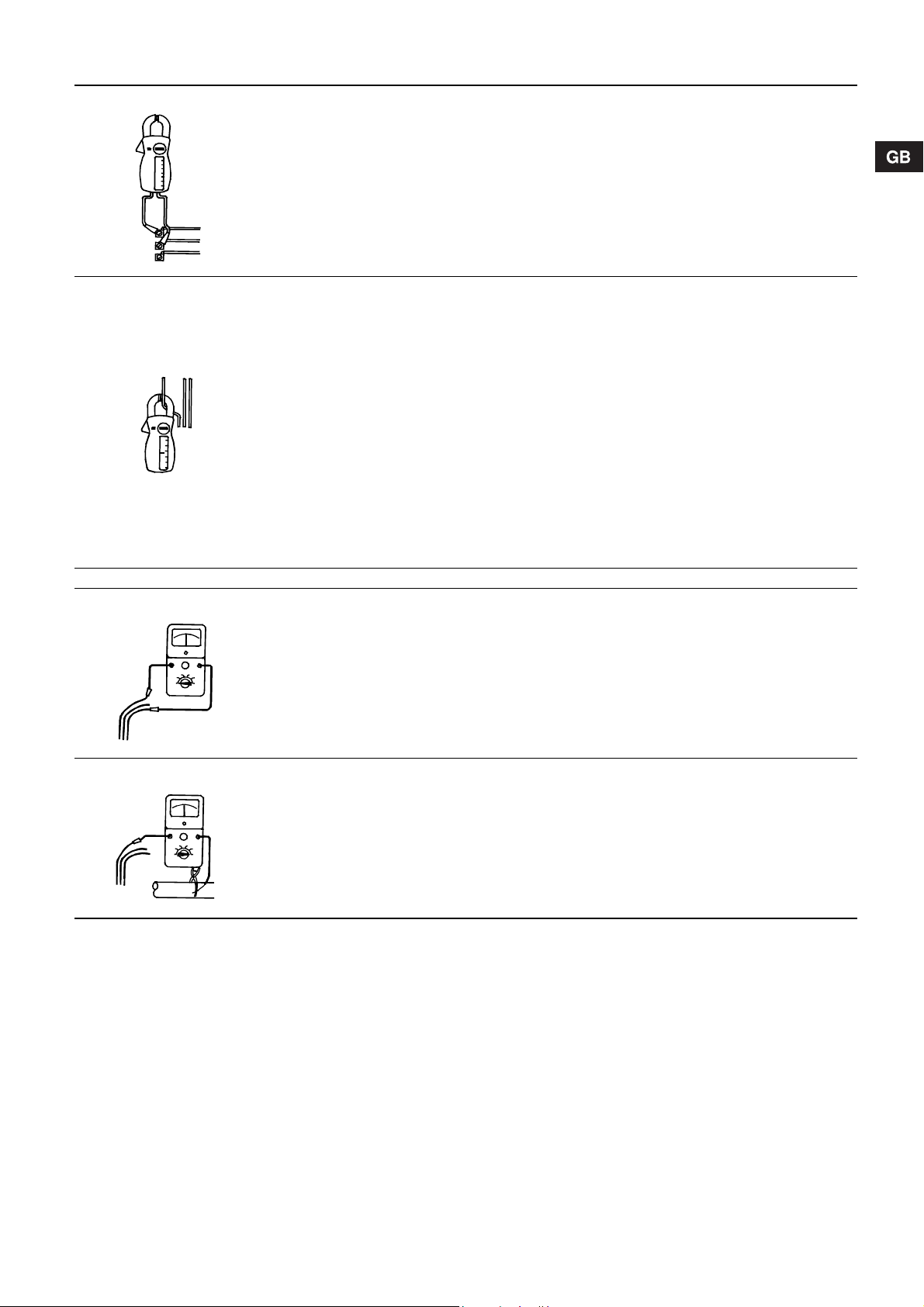
9. Checking of motor and cable
TM00 1371 5092
TM00 1372 5092
TM00 1373 5092
TM00 1374 5092
Subject to alterations.
1. Supply voltage Measure the voltage between the
phases by means of a voltmeter.
Connect the voltmeter to the terminals
in the motor starter.
The voltage should, when the motor is loaded, be within the
range specified in section 4.1 General.
The motor may burn if there are larger variations in voltage.
Large variations in voltage indicate poor electricity supply, and
the pump should be stopped until the defect has been remedied.
2. Current consumption Measure the amps of each phase while
the pump is operating at a constant
discharge head (if possible, at the
capacity where the motor is most heavily loaded).
For maximum operating current, see
nameplate.
The difference between the current in the phase with the
highest consumption and the current in the phase with the
lowest consumption should not exceed 5%.
If so, or if the current exceeds the full load current, there are
the following possible faults:
• The contacts of the motor starter burnt. Replace the contacts.
• Poor connection in leads, possibly in the cable joint. See
item 3.
• Too high or too low supply voltage. See item 1.
• The motor windings are short-circuited or partly disjointed.
See item 3.
• Damaged pump is causing the motor to be overloaded. Pull
out the pump for overhaul.
• The resistance value of the motor windings deviates too
much. Move the phases in phase order to a more uniform
load. If this does not help, see item 3.
Items 3 and 4: Measurement is not necessary when the supply voltage and the current consumption are normal.
3. Winding resistance Disconnect th e submersible drop cable
at the motor starter.
Measure the winding resistance
between the leads of the drop cable.
The difference between the highest and the lowest value
should not exceed 5%.
If the deviation is higher, pull out the pump.
Measure motor, motor cable and drop cable separately, and
repair/replace defective parts.
4. Insulation resistance Disconnect the submersible drop cable
at the motor starter.
Measure the insulation resistance from
each phase to earth (frame).
Make sure that the earth connection is
made carefully.
10. Disposal
Disposal of this product or parts of it must be carried out according to the following guidelines:
1. Use the local public or private waste collection service.
2. In case such waste collection service does not exist or cannot
handle the materials used in the product, please deliver the
product or any hazardous materials from it to your nearest
GRUNDFOS company or service workshop.
If the insulation resistance is less than 0.5 M, the pump
should be pulled out for motor or cable repair.
Local regulations may specify other values for the insulation
resistance.
13
Page 14

Pump
Pumpe
Pompe
Pompa
Bomba
Bomba
Αντλία
Pomp
Pump
Pumppu
Pumpe
Maximum Diameter of Pump/Motor [mm]
Max. Pumpen-/Motordurchmesser [mm]
Diamètre maximum de la pompe/du moteur [mm]
Massimo diametro della pompa/motore [mm]
Máximo diámetro de bomba/motor [mm]
Diâmetro máximo da bomba/motor [mm]
Μέγιστη Διάμετρος Αντλίας /Κινητήρα [mm]
Maximale diameter van de pomp/motor [mm]
Max. pump-/motordiameter [mm]
Pumpun/moottorin suurin halkaisija [mm]
Maks. pumpe-/motordiameter [mm]
Motor - Motor - Moteur - Motore - Motor - Motor - Κινητήρας
Type
Typ
Type
Tipo
Tipo
Tipo
Τύπ ος
Type
Typ
Tyyppi
Type
SP 55 DN 100 242 242 242 242
SP 90 DN 100 242 242 242 242
SP 270 DN 175 290 290 290 290 290 290
SP 300 DN 175 290 290 290 290 290 290
SP 360 DN 175 290 290 290 290 290 290
Flange
Flansch
Bride
Flangia
Brida
Flange
Φλάντζα
Flens
Fläns
Laippa
Flange
Direct-On-Line Starting
Direktanlauf
Démarrage direct
Avviamento diretto
Arranque directo
Arranque directo
Απευθείας Εκκίνηση
Directe aanloop
Direktstart
Suorakäynnistys
Direkte start
6" 8" 10" 12" 6" 8" 10" 12"
Motor - Motor - Moottori - Motor
Star-Delta Starting
Stern-Dreieck-Anlauf
Démarrage étoile-triangle
Avviamento Y/
Arranque estrella-triángulo
Arranque estrela-triângulo
Εκκίνηση Αστέρα-Τριγώνου
Ster/driehoek-aanloop
Y/-start
Y/-käynnistys
Y/-start
109
Page 15

Example:
U = 3 x 400 V
I=40 A
L = 140 m
U=2%
Lx
L
U
------- -
140
2
------------
70 m q25mm
2
== = =
TM00 1346 5092
I = 40 A
U = 2%
U = 3 x 400 V
L = 140 m
Example:
U = 3 x 380 V
I=10 A
L = 120 m
U=2%
Lx
L
U
------- -
120
2
------------
60 m q6mm
2
== = =
TM00 1345 5092
I = 10 A
U = 2%
U = 3 x 380 V
L = 120 m
110
Page 16

Example:
U = 3 x 220 V
I=5 A
L = 105 m
U=3%
Lx
L
U
------- -
105
3
------------
35 m q25,mm
2
== = =
TM00 1348 5092
I = 5 A
U = 3%
U = 3 x 220 V
L = 105 m
Example:
U = 3 x 415 V
I=100 A
L = 150 m
U=3%
Lx
L
U
------- -
150
3
------------
50 m q50mm
2
== = =
TM00 1347 5092
I = 100 A
U = 3%
U = 3 x 415 V
L = 150 m
111
Page 17

112
Page 18

113
Page 19

114
Page 20

Argentina
Bombas GRUNDFOS de Argentina S.A.
Ruta Panamericana km. 37.500 Lote 34A
1619 - Garin
Pcia. de Buenos Aires
Phone: +54-3327 414 444
Telefax: +54-3327 411 111
Australia
GRUNDFOS Pumps Pty. Ltd.
P.O. Box 2040
Regency Park
South Australia 5942
Phone: +61-8-8461-4611
Telefax: +61-8-8340 0155
Austria
GRUNDFOS Pumpen Vertrieb Ges.m.b.H.
Grundfosstraße 2
A-5082 Grödig/Salzburg
Tel.: +43-6246-883-0
Telefax: +43-6246-883-30
Belgium
N.V. GRUNDFOS Bellux S.A.
Boomsesteenweg 81-83
B-2630 Aartselaar
Tél.: +32-3-870 7300
Télécopie: +32-3-870 7301
Belorussia
Представительство ГРУНДФОС в
Минске
220123, Минск,
ул. В. Хоружей, 22, оф. 1105
Тел.: +(37517) 233 97 65,
Факс: +(37517) 233 97 69
E-mail: grundfos_minsk@mail.ru
Bosnia/Herzegovina
GRUNDFOS Sarajevo
Trg Heroja 16,
BiH-71000 Sarajevo
Phone: +387 33 713 290
Telefax: +387 33 659 079
e-mail: grundfos@bih.net.ba
Brazil
BOMBAS GRUNDFOS DO BRASIL
Av. Humberto de Alencar Castelo Branco,
630
CEP 09850 - 300
São Bernardo do Campo - SP
Phone: +55-11 4393 5533
Telefax: +55-11 4343 5015
Bulgaria
Grundfos Bulgaria EOOD
Slatina District
Iztochna Tangenta street no. 100
BG - 1592 Sofia
Tel. +359 2 49 22 200
Fax. +359 2 49 22 201
email: bulgaria@grundfos.bg
Canada
GRUNDFOS Canada Inc.
2941 Brighton Road
Oakville, Ontario
L6H 6C9
Phone: +1-905 829 9533
Telefax: +1-905 829 9512
China
GRUNDFOS Pumps (Shanghai) Co. Ltd.
50/F Maxdo Center No. 8 XingYi Rd.
Hongqiao development Zone
Shanghai 200336
PRC
Phone: +86-021-612 252 22
Telefax: +86-021-612 253 33
Croatia
GRUNDFOS CROATIA d.o.o.
Cebini 37, Buzin
HR-10010 Zagreb
Phone: +385 1 6595 400
Telefax: +385 1 6595 499
www.grundfos.hr
Czech Republic
GRUNDFOS s.r.o.
Čajkovského 21
779 00 Olomouc
Phone: +420-585-716 111
Telefax: +420-585-716 299
Denmark
GRUNDFOS DK A/S
Martin Bachs Vej 3
DK-8850 Bjerringbro
Tlf.: +45-87 50 50 50
Telefax: +45-87 50 51 51
E-mail: info_GDK@grundfos.com
www.grundfos.com/DK
Estonia
GRUNDFOS Pumps Eesti OÜ
Peterburi tee 92G
11415 Tallinn
Tel: + 372 606 1690
Fax: + 372 606 1691
Finland
OY GRUNDFOS Pumput AB
Mestarintie 11
FIN-01730 Vantaa
Phone: +358-3066 5650
Telefax: +358-3066 56550
France
Pompes GRUNDFOS Distribution S.A.
Parc d’Activités de Chesnes
57, rue de Malacombe
F-38290 St. Quentin Fallavier (Lyon)
Tél.: +33-4 74 82 15 15
Télécopie: +33-4 74 94 10 51
Germany
GRUNDFOS GMBH
Schlüterstr. 33
40699 Erkrath
Tel.: +49-(0) 211 929 69-0
Telefax: +49-(0) 211 929 69-3799
e-mail: infoservice@grundfos.de
Service in Deutschland:
e-mail: kundendienst@grundfos.de
Greece
GRUNDFOS Hellas A.E.B.E.
20th km. Athinon-Markopoulou Av.
P.O. Bo x 7 1
GR-19002 Peania
Phone: +0030-210-66 83 400
Telefax: +0030-210-66 46 273
Hong Kong
GRUNDFOS Pumps (Hong Kong) Ltd.
Unit 1, Ground floor
Siu Wai Industrial Centre
29-33 Wing Hong Street &
68 King Lam Street, Cheung Sha Wan
Kowloon
Phone: +852-27861706 / 27861741
Telefax: +852-27858664
Hungary
GRUNDFOS Hungária Kft.
Park u. 8
H-2045 Törökbálint,
Phone: +36-23 511 110
Telefax: +36-23 511 111
India
GRUNDFOS Pumps India Private Limited
118 Old Mahabalipuram Road
Thoraipakkam
Chennai 600 096
Phone: +91-44 2496 6800
Indonesia
PT GRUNDFOS Pompa
Jl. Rawa Sumur III, Blok III / CC-1
Kawasan Industri, Pulogadung
Jakarta 13930
Phone: +62-21-460 6909
Telefax: +62-21-460 6910 / 460 6901
Ireland
GRUNDFOS (Ireland) Ltd.
Unit A, Merrywell Business Park
Ballymount Road Lower
Dublin 12
Phone: +353-1-4089 800
Telefax: +353-1-4089 830
Italy
GRUNDFOS Pompe Italia S.r.l.
Via Gran Sasso 4
I-20060 Truccazzano (Milano)
Tel.: +39-02-95838112
Telefax: +39-02-95309290 / 95838461
Japan
GRUNDFOS Pumps K.K.
Gotanda Metalion Bldg., 5F,
5-21-15, Higashi-gotanda
Shiagawa-ku, Tokyo
141-0022 Japan
Phone: +81 35 448 1391
Telefax: +81 35 448 9619
Korea
GRUNDFOS Pumps Korea Ltd.
6th Floor, Aju Building 679-5
Yeoksam-dong, Kangnam-ku, 135-916
Seoul, Korea
Phone: +82-2-5317 600
Telefax: +82-2-5633 725
Latvia
SIA GRUNDFOS Pumps Latvia
Deglava biznesa centrs
Augusta Deglava ielā 60, LV-1035, Rīga,
Tālr.: + 371 714 9640, 7 149 641
Fakss: + 371 914 9646
Lithuania
GRUNDFOS Pumps UAB
Smolensko g. 6
LT-03201 Vilnius
Tel: + 370 52 395 430
Fax: + 370 52 395 431
Malaysia
GRUNDFOS Pumps Sdn. Bhd.
7 Jalan Peguam U1/25
Glenmarie Industrial Park
40150 Shah Alam
Selangor
Phone: +60-3-5569 2922
Telefax: +60-3-5569 2866
México
Bombas GRUNDFOS de México S.A. de
C.V.
Boulevard TLC No. 15
Parque Industrial Stiva Aeropuerto
Apodaca, N.L. 66600
Phone: +52-81-8144 4000
Telefax: +52-81-8144 4010
Netherlands
GRUNDFOS Netherlands
Velu wezoom 35
1326 AE Almere
Postbus 22015
1302 CA ALMERE
Tel.: +31-88-478 6336
Telefax: +31-88-478 6332
E-mail: info_gnl@grundfos.com
New Zealand
GRUNDFOS Pumps NZ Ltd.
17 Beatrice Tinsley Crescent
North Harbour Industrial Estate
Albany, Auckland
Phone: +64-9-415 3240
Telefax: +64-9-415 3250
Norway
GRUNDFOS Pumper A/S
Strømsveien 344
Postboks 235, Leirdal
N-1011 Oslo
Tlf.: +47-22 90 47 00
Telefax: +47-22 32 21 50
Poland
GRUNDFOS Pompy Sp. z o.o.
ul. Klonowa 23
Baranowo k. Poznania
PL-62-081 Przeźmierowo
Tel: (+48-61) 650 13 00
Fax: (+48-61) 650 13 50
Portugal
Bombas GRUNDFOS Portugal, S.A.
Rua Calvet de Magalhães, 241
Apartado 1079
P-2770-153 Paço de Arcos
Tel.: +351-21-440 76 00
Telefax: +351-21-440 76 90
România
GRUNDFOS Pompe România SRL
Bd. Biruintei, nr 103
Pantelimon county Ilfov
Phone: +40 21 200 4100
Telefax: +40 21 200 4101
E-mail: romania@grundfos.ro
Russia
ООО Грундфос
Россия, 109544 Москва, ул. Школьная
39
Тел. (+7) 495 737 30 00, 564 88 00
Факс (+7) 495 737 75 36, 564 88 11
E-mail grundfos.moscow@grundfos.com
Serbia
GRUNDFOS Predstavništvo Beograd
Dr. Milutina Ivkovića 2a/29
YU-11000 Beograd
Phone: +381 11 26 47 877 / 11 26 47 496
Telefax: +381 11 26 48 340
Singapore
GRUNDFOS (Singapore) Pte. Ltd.
24 Tuas West Road
Jurong Town
Singapore 638381
Phone: +65-6865 1222
Telefax: +65-6861 8402
Slovenia
GRUNDFOS d.o.o.
Šlandrova 8b, SI-1231 Ljubljana-Črnuče
Phone: +386 1 568 0610
Telefax: +386 1 568 0619
E-mail: slovenia@grundfos.si
South Africa
Corner Mountjoy and George Allen Roads
Wilbart Ext. 2
Bedfordview 2008
Phone: (+27) 11 579 4800
Fax: (+27) 11 455 6066
E-mail: lsmart@grundfos.com
Spain
Bombas GRUNDFOS España S.A.
Camino de la Fuentecilla, s/n
E-28110 Algete (Madrid)
Tel.: +34-91-848 8800
Telefax: +34-91-628 0465
Sweden
GRUNDFOS AB
Box 333 (Lunnagårdsgatan 6)
431 24 Mölndal
Tel.: +46(0)771-32 23 00
Telefax: +46(0)31-331 94 60
Switzerland
GRUNDFOS Pumpen AG
Bruggacherstrasse 10
CH-8117 Fällanden/ZH
Tel.: +41-1-806 8111
Telefax: +41-1-806 8115
Taiwan
GRUNDFOS Pumps (Taiwan) Ltd.
7 Floor, 219 Min-Chuan Road
Taichung, Taiwan, R.O.C.
Phone: +886-4-2305 0868
Telefax: +886-4-2305 0878
Thailand
GRUNDFOS (Thailand) Ltd.
92 Chaloem Phrakiat Rama 9 Road,
Dokmai, Pravej, Bangkok 10250
Phone: +66-2-725 8999
Telefax: +66-2-725 8998
Turkey
GRUNDFOS POMPA San. ve Tic. Ltd. Sti.
Gebze Organize Sanayi Bölgesi
Ihsan dede Caddesi,
2. yol 200. Sokak No. 204
41490 Gebze/ Kocaeli
Phone: +90 - 262-679 7979
Telefax: +90 - 262-679 7905
E-mail: satis@grundfos.com
Ukraine
ТОВ ГРУНДФОС УКРАЇНА
01010 Київ, Вул. Московська 8б,
Тел.:(+38 044) 390 40 50
Фах.: (+38 044) 390 40 59
E-mail: ukraine@grundfos.com
United Arab Emirates
GRUNDFOS Gulf Distribution
P.O. Box 16768
Jebel Ali Free Zone
Dubai
Phone: +971-4- 8815 166
Telefax: +971-4-8815 136
United Kingdom
GRUNDFOS Pumps Ltd.
Grovebury Road
Leighton Buzzard/Beds. LU7 8TL
Phone: +44-1525-850000
Telefax: +44-1525-850011
U.S.A.
GRUNDFOS Pumps Corporation
17100 West 118th Terrace
Olathe, Kansas 66061
Phone: +1-913-227-3400
Telefax: +1-913-227-3500
Usbekistan
Представительство ГРУНДФОС в
Ташкенте
700000 Ташк ент ул.Усм ана Носира 1-й
тупик 5
Телефон: (3712) 55-68-15
Факс: (3712) 53-36-35
Revised 29.09.2010
Page 21

Being responsible is our foundation
Thinking ahead makes it possible
Innovation is the essence
96432078 0711
Repl. 96432078 0506
ECM: 1078259
www.grundfos.com
 Loading...