

Page 1

GRUNDFOS INSTRUCTIONS
SMART Digital - DDA
Installation and operating instr uct ions
Page 2

Declaration of conformity
Declaration of conformity
GB Declaration of Conf or mity
We, Grundfos Alldos, declare u nder o ur s ole r es ponsi bilit y t hat the p ro ducts
DDA, DDC and DDE, to w hic h this d ecl arat ion r elate s, ar e in co nf ormit y w ith
these Council directives on the approximation of the laws of the EC member
states:
– Machinery Dir e cti v e ( 2 00 6/ 42 /E C) .
Standards used: EN 809: 1998, EN ISO 12100-1+A1: 2009,
EN ISO 12100- 2+A1: 2009.
– Low Voltage Directive (2 006/95/EC) *.
Standard used: EN 60204-1+A1: 2009.
– EMC Directive (20 04/1 0 8/EC).
Standards used: EN 61000-6-2: 2005, EN 61000-6-4: 2007.
* Only for products with operating voltage > 50 VAC or >75 VDC.
Pfinztal, 1 November 2010
Ulrich Stemick
Technical Director
Grundfos Water Treatment GmbH
Reetzstr. 85, D-76327 Pfinztal, Germany
Person aut hori s ed t o compile techn i ca l f i le an d
empowered to sign the EC declaration of conformity.
2
Page 3

English (GB) Installation and operating instructions
Original installation and operating instructions.
CONTENTS
Page
1. Safety instructions
1.1 Identification of saf ety in struc tio ns in
these instructions
1.2 Qualification and training of personnel
1.3 Safety instructions for the operator/
user
1.4 Safety of the system in the event of a
failure in the dos ing pum p
1.5 Dosing chemicals
2. General
2.1 Applications
2.2 Improper operating methods
2.3 Warranty
2.4 Nameplate
2.5 Type key
2.6 Device overvi ew
3. Technical data / dimensions
3.1 Technical data
3.2 Dimensions
4. Assembly a nd in stalla t ion
4.1 Pump assembly
4.1.1 Requirements
4.1.2 Align and install mounting plate
4.1.3 Engage pump in mounting plate
4.1.4 Adjusting control cube position
4.2 Hydraulic co nn ection
4.3 Electrical connection
5. Commissioning
5.1 Setting the menu language
5.2 Deaerating the pump
5.3 Calibrating the pump
6. Operation
6.1 Control ele men ts
6.2 Display and symb ols
6.2.1 Navigation
6.2.2 Operating stat es
6.2.3 Sleep mode (energy-saving mode)
6.2.4 Overview of display symbols
6.3 Main menus
6.3.1 Operation
6.3.2 Info
6.3.3 Alarm
6.3.4 Setup
6.4 Operation m od es
6.4.1 Manual
6.4.2 Pulse
6.4.3 Analog 0/4-20 mA
6.4.4 Batch (pulse-based)
6.4.5 Dosing timer, cycle
6.4.6 Dosing timer, week
6.5 Analog outp ut
6.6 SlowMode
7 FlowControl
6.
6.8 Pressure moni tor ing
6.8.1 Pressure settin g rang es
4
6.8.2 Calibration of pressure sensor
6.9 Flow measurement
4
6.10 AutoFlowAd ap t
4
6.11 Auto deaeratio n
6.12 Key lock
4
6.13 Display Setu p
6.13.1 Units
4
6.13.2 Additional display
5
6.14 Time/date
5
6.15 Bus communic at ion
5
6.16 Inputs/outputs
5
6.16.1 Relay outputs
6
6.16.2 External stop
6
6.16.3 Empt y and low- lev el sign als
7
6.17 Basic settings
8
7. Service
9
7.1 Service system
9
7.2 Perform servic e
11
7.2.1 Dosing head over view
12
7.2.2 Dismantling t he d i ap hr ag m a nd va l ve s
12
7.2.3 Reassembling the diaphragm and
12
12
12
12
13
14
16
16
17
17
19
19
19
19
19
19
20
21
21
21
21
21
22
22
22
23
24
25
25
valves
7.3 Resetting the servic e system
7.4 Repairs
8. Faults
8.1 List of faults
8.1.1 Faults with error me ss age
8.1.2 General faults
9. Disposal
Warning
Prior to instal latio n, read thes e
installation an d ope ra t in g i ns tru c tio ns.
Installation and opera tion mus t comp ly
with local regulations and accepted
codes of good practice.
26
26
27
28
28
28
29
29
29
30
30
30
30
31
31
31
31
32
32
32
33
33
33
34
34
34
34
34
35
36
36
38
38
English (GB)
3
Page 4
1. Safety instructio ns
Caution
Note
Caution
Caution
English (GB)
These installation and operating instructions contain
general instructions that must be observed during
installation, operation and main tenance of the pump.
It must therefor e be rea d by the installation engin ee r
and the relevant qualified operator prior to
installati on an d star t-up , and mus t be av ailab le at the
installation location at all tim es.
1.1 Identifica tion o f saf ety i nstru ctio ns in
these instruction s
The safety instructions are identified by the following
symbols:
Warning
If these safety instructions are not
observed, it m ay r e sult in personal
injury!
If these safety instructions are not
observed, it may resu lt in malf un ctio n
or damage to the equipment!
Notes or instru ctions that make the job
easier and ensure safe operation.
1.2 Qualification and training of personnel
The person ne l responsible f or th e installation,
operation a nd se rvice must b e ap pr op r iately
qualified for these tasks . Ar eas of resp onsib ility,
levels of au th or ity a nd th e su pe rvision of the
personnel must be precisely defined by the operator.
If necessary, the personnel must b e tr ain e d
appropriately.
Risks of not observing the safety instructions
Non-observance of the safety instructions may have
dangerous consequences for the personnel, the
environment an d the pu mp and ma y resu lt in th e loss
of any claims for da mage s.
It may lead to th e following hazards:
• Personal inju ry fr om e xposure to el ect ric al ,
mechanical and chemical influences.
• Damage to the environment and personal injury
from leakage of h ar mf ul su bstances.
1.3 Safety instructions for the
operator/user
The safety instr uc ti o ns de scr ib ed in th es e
instructions, existing national regulations on health
protection, environmental protection and for accident
prevention and an y inter nal working , op erat ing an d
safety regulation s of the op era tor mu st be obse rved .
Information attac he d to th e pu m p m u st be o bse r ved .
Leakages of dangerous substances must be
disposed of in a way that is not harmful to the
personnel or th e en vir on m en t.
Damage caused by electrical energy must be
prevented, see the regulations of the local electricity
supply company.
Before any work to the pump, the pump
must be in the ’Stop’ operational state
or be disconnected from the mains.
The system must be pressureless!
Only orginal accessories and original spare parts
should be use d. Us i ng o the r par ts ca n re sult in
exemption from liability f or a ny resu lti ng
consequences.
1.4 Safety of the system in the event of a
failure in the dosing pump
The dosing p ump was designed a cco rd i n g t o th e
latest technolo gies an d is car efull y manu factu red
and tested.
If it fails regard les s o f th is, th e s af et y o f t he ov era ll
system must be ensured. Use the relevant
monitoring and control functions for this.
Make sure t ha t an y c he m ic al s th at a r e
released fr o m th e p u mp or any
damaged lines do not cause damage to
system parts and buildings.
The installation of leak monitoring
solutions and drip trays is
recommended.
4
Page 5
1.5 Dosing chemica ls
Caution
Caution
Caution
Warning
Before swit ch i ng t h e su ppl y voltage
back on, the dosing lines must be
connected in su ch a wa y that an y
chemicals in the dosi ng he ad ca nnot
spray out and put people at risk.
The dosing medium is pressurised and
can be harmful to health and the
environment.
Warning
When working with chemicals, the
accident prevention regulations
applicable a t t h e in st al la ti on s it e
should be applied (e. g. wearing
protective clothing).
Observe the chemical manufacturer's
safety data sheets and safety
instructions when handling chemicals!
Warning
If the diaphragm leaks or is broken,
dosing liquid will escape from the
discharge opening on the dosing head
(see fig. 3).
Take suitable precautions to prevent
harm to health and damage to property
from escapi ng do sin g li qui d!
Check daily whether liquid is escaping
from the disch arg e ope nin g!
Changing the di aph rag m, se e sect ion
7. S e r vice.
A deaeration hose, which is routed into
a container, e. g. a drip tray, must be
connected to the deaeration valve.
The dosing medium must be in liquid
aggregate stat e!
Observe the free zing and b oiling points
of the dosing medium!
The resistance of the parts that come
into contact with the dosing medium,
such as the dosing head, valve ball,
gaskets and lines, depends on the
medium, media temperature and
operating pressure.
Ensure that parts in contact with the
dosing med ia are resist an t to the
dosing medium under operating
conditions, see data booklet!
Should you have any questions
regarding the material resistance and
suitability o f t he p u mp fo r s p ec if ic
dosing media, please contact
Grundfos.
2. General
The DDA dosing pump is a self-priming
diaphragm pu m p. It co ns i sts o f a h ou si n g
with stepper motor and electronics, a
dosing head with diaphragm and valves and the
control cube.
Excellent dosi ng fe at ur es o f t he p um p:
• Optimal intake even with degassing media, as
the pump always wor ks a t full su ct ion s troke
volume.
• Continuous dosing, as the medium is sucked up
with a short suction str oke, reg ardle ss of the
current dos ing flow, and dosed with t he lo ng est
possible dosing stroke.
2.1 Application s
The pump is suita ble for liquid, no n- ab ra si v e, no n flammable and non-combustible media strictly in
accordance with the inst ructions in these installation
and operating instructions.
Areas of applic at io n
• Drinking water treatment
• Wastewater treatm ent
• Swimming pool water treatment
• Boiler water treatment
• CIP (Clean -In-Place)
• Cooling wate r tr ea tm e nt
• Process wate r tr ea tm en t
• Wash plants
• Chemical industry
• Ultrafiltration processes and reverse osmosis
•Irrigation
• Paper and pulp industry
• Food and beverage industries
2.2 Improper operating methods
The operational safety of the pump is only
guaranteed if it is used in accordance with section
2.1 A pp l ications.
Warning
Other applications or the operation of
pumps in ambient and operating
conditions, which are not approved,
are considered improper and are not
permitted. Grundfos cannot be held
liable for an y da mag e r es u lt in g fr o m
incorrect use.
Warning
The pump is NOT approved for
operation in potentially explosive
areas!
Warning
A sunscreen is required for outdoor
installation !
English (GB)
5
Page 6

2.3 Warranty
psi
gphl/h
P
Type designation
Voltage
Frequency
Max. dosing flow
Power consumption
Enclosure class
Mark of approval, CE mark, etc.
Model
Current consumption
Country of production
Max. operating pressure
English (GB)
A guarantee claim in acco rd ance wit h our gene ral t erms o f s ale a nd deli ver y is only va lid if the fo llow ing
requiremen ts are ful fille d:
• The pump is use d in accordance wit h t he information w ith i n th is m a nu al .
• The pump is not dismantled or incorrectly handled.
• The maintenance is carried out by authorised and qualified personnel.
• Original spare parts are used for repairs during maintenance.
2.4 Nameplate
Fig. 1 Nameplate
TM04 1116 1110
6
Page 7

2.5 Type key
The type key i s us ed t o identify the p r eci se pump and is n ot us ed f or co nf i gu r ati on p ur po se s.
Code Example DDA 7.5- 16 AR- PP/ V/ C- F- 3 1 U2U2 F G
Pump type
Max. flow [l/h]
Max. pressure [bar]
Control variant
AR
Standard
FC
AR with FlowControl
FCM
FC with integrated flow measurement
Dosing head material
PP
Polypropylene
PVC
PVC (polyvinyl chloride) (PVC dosing heads onl y up to 1 0 bar)
PV
PVDF (polyvinylidene fluoride)
SS
Stainless steel DIN 1.4401
PVC-P3
PVC with Plus
Gasket material
E
EPDM
V
FKM
T
PTFE
Valve ball material
C
Ceramic
SS
Stainless steel DIN 1.4401
Control cube position
F
Front-mounted (can be changed to the right o r left)
Voltage
3
1 x 100-240 V, 50/60 Hz
Valve type
1
Standard
2
Spring-loaded (HV version)
Suction/discharge side connection
U2U2
Hose, 4/6 mm, 6/9 mm, 6/12 mm, 9/12 mm
U7U7
Hose 1/8" x 1/4"; 0.17" x 1/4"; 1/4" x 3/8"; 3/8" x 1 /2"
AA
Threaded Rp 1/4", female (stainless steel)
VV
Threaded 1/4" NPT, female (stainless steel)
XX
No connection
Installation set*
I001
Hose, 4/6 mm (up to 7.5 l/h, 16 bar)
I002
Hose, 9/12 mm (up to 60 l/h, 13 bar)
I003
Hose 0.17" x 1/4" (up to 7.5 l/h, 16 bar)
I004
Hose, 3/8" x 1/2" (up to 60 l/h, 10 bar)
Power plug
F
EU (Schuko)
B
USA, Canada
G
UK
I
Australia, New Zealand, Taiwan
E
Switzerland
J
Japan
L
Argentina
Design
G
Grundfos Alldos
*) including: 2 pump connections, foot valve, injection unit, 6 m PE discharge hose, 2 m PVC suction hose,
2 m PVC deaeration hose (4/6 mm)
3
English (GB)
7
Page 8

2.6 Device overview
Start/stop key
(Sect. 6.1)
Mains connection
Control cube
Graphic LC display
(Sect. 6.2.2)
Click wheel (Sect. 6.1)
100 % key (Sect.6.1)
Signal inputs, outputs
(Sect. 4.3)
Mounting plate
100%100%
FlowControl connection
FC/FCM
Deaeration valve
Dosing head
Valve, suction side
Connection, deaeration
hose
Valve, discharge side
Control cube assembly
screws
Drain opening in cas e of
diaphragm breakage
English (GB)
Fig. 2 Front view of the pump
TM04 1129 0110
Fig. 3 Rear view of th e pu m p
8
TM04 1133 0110
Page 9

3. Technical data / dimensions
3.1 Technical data
Data
Mechanica l
data
DDA pump type
7.5 - 16 12-10 17-7 30-4
Turndown ration (setting range) [1:X] 3000 1000 1000 1000
Max. dosing flow
Max. dosing flow with SlowMode 50 %
Max. dosing flow with SlowMode 25 %
Min. dosing flow
Max. operatin g pr es sur e
Max. stroke freq ue ncy
1)
[l/h] 7.5 12.0 17.0 30.0
[gph] 2.0 3.1 4.5 8.0
[l/h] 3.75 6.00 8.50 15 .0 0
[gph] 1.00 1.55 2.25 4.00
[l/h] 1.88 3.00 4.25 7.50
[gph] 0.50 0.78 1.13 2.00
[l/h] 0.0025 0.0120 0.0170 0.0 30 0
[gph] 0.0007 0.0031 0.0045 0.0080
[bar] 16 10 7 4
[psi] 230 150 100 60
[Strokes/
min]
190 155 205 180
Stroke volume [ml] 0.74 1.45 1.55 3.10
Accuracy of repeatability [%] ±1
Max. suction lift during operation
Max. suction lift when pr imi ng wit h wet
2)
valves
Min. pressure difference between suction
and discharge side
2)
[m] 6
[m] 2 3 3 2
[bar] 1 (FC and FCM: 2)
Max. pressure, suctio n side [bar] 2
Max. viscosity in S lowMode 25 % with
spring-loaded valves
Max. viscosity in S lowMode 50 % with
spring-loaded valves
Max. viscosity without Slow Mode with
spring-loaded valves
Max. viscosity without spring-loaded
3)
valves
Min. diameter of hose/pipe on suction/
discharge side
Min. diameter of hose/pipe on suction
side for highly viscous media (HV)
Min. diameter of hose/pipe on discharge
side for highly viscous media (HV)
3)
3)
3)
2) 4)
4)
4)
[mPa s]
(= cP)
[mPa s]
(= cP)
[mPa s]
(= cP)
[mPa s]
(= cP)
2500 2500 2000 1500
1800 1300 130 0 600
600 500 500 200
50 300 300 150
[mm] 4 6 6 9
[mm] 9
[mm] 9
Max. media te mp er ature [°C] 45
Min. media temp erat ur e [°C] -10
Max. ambient tem p er at ur e [°C] 45
Min. ambient tem per atur e [°C] 0
Max. storage te mp er at ur e [°C] 70
Min. storage temperature [°C] -20
English (GB)
9
Page 10

English (GB)
DDA pump type
Data
7.5 - 16 12-10 17-7 30-4
Voltage [V] 100-240 V, 50-60 Hz
Length of ma ins ca ble [m] 1.5
Max. current co nsu m pti on ( 10 0 V ) [A] 8
Electrical
data
Max. current co nsu m pti on ( 23 0 V ) [A] 25
Max. power co nsu m ption P
1
[W] 18 / 24
Enclosure class IP 65, Nema 4X
Electrical safety cla ss II
Max. load for level input 12 V, 5 mA
Max. load for pu ls e in pu t 12 V, 5 mA
Max. load for external stop 12 V, 5 mA
Signal input
Min. pulse length [ms] 5
Max. pulse frequency [Hz] 100
Impedance at 0/ 4-20 mA analo g input [Ω]15
Max. resistance in level circuit [Ω]1000
Max. resistance in pulse circuit [Ω]1000
Max. ohmic load on r elay o ut pu t [A] 0.5
Signal
output
Max. voltage on relay output [V] 30 VDC / 30 VAC
Impedance at 0/ 4-20 m A a nalog output [Ω]500
Weight (PVC, PP, PVDF) [kg] 2.4 2.4 2.6
Weight/ size
Weight (stainless steel) [kg] 3.2 3.2 4.0
Diaphragm diameter [mm] 44 50 74
Sound
pressure
level
Max. sound pr es su re le vel [dB(A)] 60
Approvals CE, CSA-US, NSF61, G HOS T, C-Tick
5)
1)
The maximum stroke frequency varies depending on calibration
2)
Data is based on measu rements wi th water
3)
Maximum suction lift: 1 m, dosing flow reduced (approx. 30 %)
4)
Length of suction line: 1.5 m / length of discharge line: 10 m (at max. viscosity)
5)
With E-Box.
10
Page 11
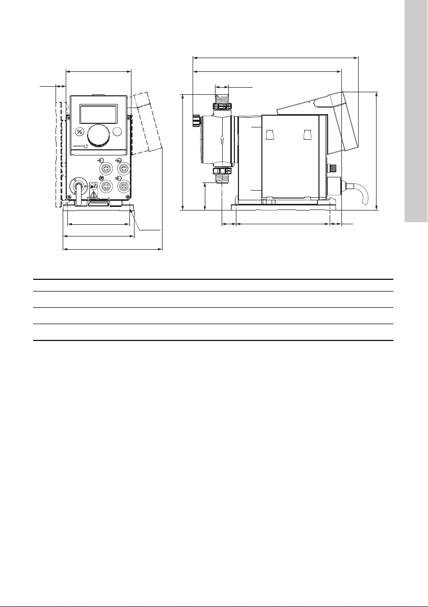
3.2 Dimensions
161
17
D
B
C
A1
G 5/8"
A
200.8
100%
110
4 x Ø6
105
120
17.5
168
Fig. 4 Dimensional draw ing
Pump type A [mm] A1 [mm] B [mm] C [mm] D [mm]
DDA 7.5 - 16 280 251 196 46.5 24
DDA 12-10/17-7 280 251 200.5 39.5 24
DDA 30-4 295 267 204.5 35.5 38.5
English (GB)
TM04 1103 0110
11
Page 12
4. Assembly and installation
Caution
Caution
IP65, Nema 4X
English (GB)
4.1 Pump assembly
The pump is deli vered with a moun tin g plat e.
The mountin g pl a te c an b e m ounted vertic al ly
e. g. on a wall or hor i zo ntally e. g. on a tank. It take s
just a few quick ste ps to f i rmly se cur e th e pu m p t o
the mounting plate by means of a slot mechanism.
The pump can easily be released from the mounting
plate for maintenance.
4.1.1 Requirements
• The mounting surface must be stable and must
not vibrate.
• Dosing must flow upwards vertically.
4.1.2 Align and install mounting plate
• Vertical installation: Mounting plate slot
mechanism must be above.
• Horizontal installatio n : Mounting plate slot
mechanism mu st be o pp os ite th e do si n g he ad .
• The mounting plate can be used as a drill
template, please see fig. 4 for drill hole distances.
Fig. 5 Locate mounting plate
Warning
Make sure that you do no t damage any
cables and lines during installation!
1. Indicate drill holes.
2. Dr ill h ol es.
3. Secure mounting plate u sin g fo ur screws,
diameter 5 mm, to the wa ll, o n th e b ra ck et or th e
tank.
4.1.3 Engage pump in mounting plate
1. Attach the pump to the mounting plate support
clamps and slide under slight pressure until it
engages.
Fig. 6 Engaging the pump
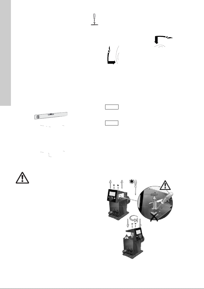
4.1.4 Adjusting control cube position
The control cub e is f i tt ed to t he fr o nt of th e pu m p on
delivery. It can be turned by 90 ° so that the user can
select to oper at e th e pump from th e r ig ht or left side.
The enclos ur e c lass (IP65 / Nema 4X)
and shock protection are only
guaranteed if the control cube is
installed correctly!
Pump must be disconnected from the
power supply!
1. Carefully remove both pr o t ec tive caps on the
control cube using a thin screwdriver.
2. Loosen screws.
3. Carefully lift off control cube on ly s o fa r f ro m th e
pump housing that no tensile stress is produced
on the flat band cable.
4. Turn control cube by 90 ° and re-attach.
TM04 1162 0110
– Make sure th e O- r ing is se cur e .
5. Tighten screws slightly and attach protective
caps.
TM04 1159 0110
12
TM04 1182 0110
Fig. 7 Adjusting contro l c ube
Page 13

4.2 Hydraulic connection
Caution
Caution
Caution
Note
Caution
Union nut
Tensioning ri ng
Cone part
Hose
Deaeration
hose
Tank
Multifunction
valve
Suction line
with empty
signal
Warning
Risk of chemical b urns!
Wear protective clothing (gloves and
goggles) when working on the dosing
head, connections or lines!
The dosing head may contain water
from the factory check!
When dosing media which should not
come into co n ta ct w ith wa ter, another
medium must be dosed beforehand!
Faultless function can only be
guaranteed in conjunction with lines
supplied by Grundfos!
The lines used must comply with the
pressure lim it s as per sectio n
3.1 Tech nica l dat a!
Important information on installation
• Observe suction lift and line diameter, see
section 3.1 Technical data.
• Shorten hos es a t r i gh t an gle s .
• Ensure that th er e ar e no lo o ps or kinks in the
hoses.
• Keep suction line as short as possible.
• R oute suctio n line up towards the suctio n valve.
• Installing a filter in the su cti on li n e pr ot ec ts th e
entire installatio n again st di rt and re duce s the
risk of leakage.
• Only control varia n t FC/ FC M: For disch ar g e
quantities < 1 l/h we recommend the use of an
additional spring-loaded valve (approx. 3 bar) on
the discharge side for the saf e gene rati on of the
necessary differential pressure.
Hose connection procedure
1. Push union nut and te nsioning ring a cr oss h ose .
2. Push cone part fully into ho se , s ee fig . 8.
3. Attach cone part with ho se to co rr e spo nding
pump valve.
4. Tighten union nut manual l y.
– do not use tools!
5. Tighten up union nuts after 2-5 operating hours if
using PTFE gaske ts!
6. Attach deaeration hose to the corresponding
connection ( see fig. 3) and ru n i nt o a c on tai ne r
or a collec ting tray.
Fig. 8 Hydraulic connection
Pressure differential between suction
and discharge side must be at least
1 bar / 14.5 psi!
Tighten up the dosing head screws
once before commissioning and after
2-5 operating hours at 3 Nm.
Installation ex ample
The pump offers various installation options. In the
picture below, the pump is installed in conjunction
with a suction line, l evel s witch and multifunction
valve on a Grundfos tank.
English (GB)
TM04 1155 0110
TM04 1183 0110
Fig. 9 Installation example
13
Page 14

4.3 Electrical connection
2
1
3
4
2
1
3
4
5
2
3
4
1
2
1
3
►
2
1
GND
GND
BUS
BUS
GND
12
34
12
34
12
5
34
34
12
English (GB)
Warning
The enclosure class (IP65 / Nema 4X) is only guaranteed if plugs or protective caps are
correctly ins ta lle d!
Warning
The pump c an s ta r t au t oma tically when t h e ma in s v ol ta g e is switched on !
Do not manipulate mains plug or cable!
The rated voltage of the pump, see section 2.4 Nameplate , mu st confor m to local conditions .
Signal connections
Fig. 10 Wiring diagram of the electrical connections
14
TM04 1121 0110
Page 15

Analog, external stop and pulse input
Sensor
Function
Analog GND/ (-) mA (+) mA mA signal
External stop GND X Pulse
Pulse GND X Pulse
Level signals: empty and low-level signal
Function
Low-level signal X GND Pu lse
Empty signal X GND Pulse
GENIbus, analog output
Function
GENIbus +30 V
Analog output (+) mA GND/ (-) mA mA signal
Relay outputs
Function
Relay 1 X X Pulse
Relay 2 X X Pulse
1/brown 2/white 3/blue 4/black
1/brown 2/white 3/blue 4/black
1/brown 2/white 3/blue 4/black
GENI bus
TXD
1/brown 2/white 3/blue 4/black
Pins
Pins
Pins
GENI bus
RXD
Pins
5/yellow/
green
GND Bus
Plug type
English (GB)
Plug type
Plug type
Plug type
FlowControl signal connection
Fig. 11 FlowControl connec ti o n
TM04 1158 0110
15
Page 16

5. Commissioning
Operation
English >
Manual >
Actual flow
Off
❑
Language
Operation mode
Analog output
SlowMode
FlowControl active
Operation
Setup
Setup
Setup
Setup
Setup
l/h
Manual
7.50
l/h
Manual
English >
Manual >
Actual flow
Off
❑
Language
Operation mode
Analog output
SlowMode
FlowControl active
❑
❑
❑
❑
English
Deutsch
Francais
Espanol
Italiano
❑
❑
❑
❑
English
Deutsch
Francais
Espanol
Italiano
Confirm
settings?
7.50
English (GB)
5.1 Setting the menu language
For description of control elements, see Section 6.
1. Turn click wheel to highlight the cog symbol.
2. Press the click wheel to op en the ’Setup’ menu.
3. Turn the click wheel to highlight the ’Language’
menu.
4. Press the click wheel to op en the ’Langu ag e’
menu.
5. Turn the click wheel to highlight the desired
language.
6. Press the click wheel to se lec t the hi ghlig hted
language.
7. Press the click wheel a gain to c onfir m the
’Confirm settings’ prompt and apply the setting.
16
TM04 1184 1110
Fig. 12 Set menu language
Page 17

5.2 Deaerating the p ump
Note
Warning
The deaeration hose must be
connected corr ectl y a nd i ns ert ed int o a
suitable tank !
1. Open deaeration screw by approximately half a
turn.
2. Press and hold down the 100 % key (deaeration
key) until liqui d f lows continuously wit ho ut any
bubbles from th e de ae ra tio n ho se.
3. Close deaeration screw.
Press the 10 0 % ke y an d
simultaneously t u rn t h e clickwheel
clockwise to i nc rease the dur at io n of
the process to up to 3 00 s ec onds . Af ter
setting the seconds, do not press the
key any longer.
5.3 Calibrating the pump
The pump is calibrated in the factory for media with a
viscosity similar to water at maximum pump
backpressure (se e sec tio n 3. 1 Technical data) .
If the pump is op er at ed with a backp r ess ur e th at
deviates or if dosing a medium whose viscosity
deviates, the pump must be calibrated.
For pumps with FCM c ontr ol varia nt , it is not
necessary to ca libr a te th e pu mp if t he re is de via tin g
or fluctuating backpressure as long as the
’AutoFlowA da pt’ function has been enabled
(see section 6.10 AutoFlowAd ap t).
Requirements
• The hydraulic s a nd e l ec tr ics of th e pump are
connected (se e se ctio n 4. Assembly and
installation).
• The pump is integrated into the dosing process
under operating conditions.
• The dosing h ea d an d suc ti o n ho se ar e filled with
dosing medium.
• The pump has been dea erat ed.
English (GB)
17
Page 18

Calibration process - example for DDA 7.5 - 16
V2 = 170 ml
V
d
= V1-V2= 130 ml
V
1
= 300 ml
Calibration
Calibration
Strokes
Calibrat. volu m e
200
STOP
START
0.0 ml
Strokes
Calibrat. volume
200
125 ml
Calibration
Calibrat. volu me
STOP
START
ml
Strokes
200
130
Actual dosed volum e V
d
English (GB)
1. Fill a measuring beaker with dosing med ium .
Recommended filling volumes:
DDA type 7.5 - 16 1 2-10 17-7 30-4
Medium V
2. Read off and note down the fill vo lu me V
(e.g.300ml).
0.3 l 0.5 l 1.0 l 1.5 l
1
1
3. Place the suction hose in the measuri ng beak er.
4. Start the calibration process in the ’Setup >
5. The pump executes 200 dosing strok es and
6. Remove the suction hose from the measuring
7. From V
Calibration’ menu.
displays the fa ctory ca lib ra tio n val ue
(e.g.125ml).
beaker and check the remaining volume V
(e.g.170ml).
and V2 , calculate th e ac tu al dosed
1
volume V
(e. g. 300 ml - 170 ml = 130 ml).
= V1-V
d
2
2
8. Set and apply V
– The pump is calibrated.
18
in the calibration menu.
d
TM04 1154 1110
Page 19

6. Operation
100%
7.49 l/h
Manual
7.50
l/h
Operation
Start/stop key
Graphical LC
display
Click wheel
100 % key
6.1 Control elements
The pump control p an el inc lud es a di spl ay
and the foll o wi n g con tr ol elements.
Fig. 13 Control panel
Keys
Key Function
Start/stop
key
100 % key
Click wheel
The click wheel is u sed t o navig at e thr oug h t he
menus, select setting s and con firm them.
Turning the clickwheel clockwise moves the cursor
clockwise in increments in the d isp l ay. Turning the
clickwheel anti-clockw ise move s the curso r anticlockwise.
Starting and stopping the pump.
The pump doses at maximum flow
regardless of the operation mode.
6.2 Display and symb ols
6.2.1 Naviga tion
In the ’Info’, ’Alarm’ and ’Setup’ main menus, the
options and submenus are displayed in the rows
below. Use the ’Back’ s ym bo l to r et ur n to th e higher
menu level. The scroll bar at the right edge of the
display indicates that there are further menu items
which are not shown.
The active symbol (current cursor position) flashes.
Press the click wheel to co nfirm you r s elect ion a nd
open the next menu level. The active main menu is
displayed as text, the other main menus are
displayed as sy mb ols. The positi on o f t he cu rsor is
highlighted in bla ck in the sub- menu s.
When you posit i on t he cu rs or o n a value and press
the click wheel, a value is selected. Turning the
clickwheel clockwise increases the value, turning the
clickwheel anti-clockwise reduces the value. When
you now press the click wheel, the cursor will be
released again.
6.2.2 Operati ng states
TM04 1104 1120
The operating state of the pump is indicated by a
symbol and display c olour.
Display Fault Operating state
White -
Green -
Yellow Warning
Red Alarm
6.2.3 Sleep mo de (e ner gy-sa vi ng mod e)
If in the ’Operation’ main menu the pump is not
operated for 30 seconds, the header disappears.
After 2 minutes, the display switc hes to the
’Operation’ main menu and the display brightness is
reduced. This state will be cancelled when the pump
is operated or a fault oc cu rs.
Stop Standby
Stop Standby Running
Stop Standby
English (GB)
Running
19
Page 20

6.2.4 Overview of display symbols
100%
Operation
Operation
Operating state (Sect. 6.2) and
dosing flow
7.48
l/h
Manual
7.48l/h
Operation mode
Activated functions
Top row with main menus (Sect. 6.3)
Info
Alarm
Setup
Back
SlowMode (Sec t. 6.6)
FlowControl ( Sect. 6. 7)
Key lock (Sect. 6.12)
Bus (Sect.6.15)
Auto deaeration (Sect. 6.11)
Manual (Sect . 6.4.1)
Pulse (Sect. 6.4.2)
Analog 0/4-20 mA (Sect.6.4.3)
Batch (Sect. 6.4.4)
Timer (Sect. 6.4.5, 6.4. 6)
Running
Standby
Stop
Deaerating
Diaphragm position 'out’ (Sect. 7.)
Additional display (Sect. 6.13.2)
AR, FC variant: Target flow
FCM variant: Actual flow
Remaining batch volume (Batch/Timer)
Time until next dosing process (Timer)
Input current ( A na log )
Blocked driv e - f l as hin g sym b ol
Run display
Running - rotates when pump is dosing
External stop ( Sect . 6.16.2)
Empty signal (Sect. 6.16.3)
Low-level signal (Sect. 6.16.3)
Cable break (Sect. 6.4.3)
E-box (Sect.6.15)
Service (Sect.7.)
Total dosed volume
Actual backpress ure
Signal and error display
Diaphragm position ’in’ (Sect. 7.)
English (GB)
The following d isplay symbols m ay ap pe ar i n t he m enu s .
Fig. 14 Overview of display symbols
20
TM04 1161 1710
Page 21

6.3 Main menus
Operation
7.48
l/h
Manual
7.48l/h
Th
Backpressure
Counters
Service
ServiceKit
Reset service syste m
Software rev.
Serial no.:
Product no.:
Typ e K e y
Info
18.02.2010 12:34
15.0bar
>
-
❑
V0.20
Alarm
12.02.2010
12.02.2010
1
Empty
2
Low level
12:34
12:34
Delete alarm
messages
❑
Setup
Deutsch >
Pulse >
❑
>
1.06 l
7:50
>
>
Actual flow >
Off >
❑
>
>
❑
❑
>
Off >
>
>
>
>
>
Language
Operation mode
Pulse memory *
Analog scaling *
Batch volume *
Dosing time *
Dos. Timer Cycle *
Dos. Timer Week *
Analog output
SlowMode
FlowControl active *
FlowControl *
Pressure moni torin g *
AutoFlowAdapt *
Auto deaerati on
Calibration
Key lock
Display
Time+date
Bus *
Inputs/Outputs
Basic settings
Section
5.1
6.4
6.4.2
6.4.3
6.4.4
6.4.4
6.4.5
6.4.6
6.5
6.6
6.7
6.7
6.8
6.10
6.11
5.3
6.12
6.13
6.14
6.15
6.16
6.17
The main menus are dis pl aye d as sy m bols at the t op
of the displa y. The curren tly active main me nu i s
displayed as text.
6.3.1 Operation
Status information such as th e dosin g flow,
selected operation mode and operating state
is displayed in the ’Operation’ main menu.
6.3.2 Info
You can find the date, time and informati on
about the active dosing process, various
counters, product data and the service system status
in the ’Info’ main menu. The information can be
accessed during operation.
The service syst em c an a lso b e r e set fr o m he re.
6.3.3 Alarm
You can view errors in the ’Alarm’ main menu.
Up to 10 warning s a n d a la rm s, to ge th er wi th th eir
date, time and cause , are lis ted in chrono logica l
TM04 1157 1010TM04 1106 1010
order. If the list is full, the old est e nt ry will be
overwritten, see Section 8. Faul ts.
6.3.4 Setup
The ’Setup’ main menu contains menus for
pump configuration. These menus are
described in the followin g s ec tions.
English (GB)
TM04 1109 1010TM04 1110 1010
Counters
The ’Info > counters’ menu contains the fol lowing
counters:
Counters resettable
Volume
Total dosed volume [l] or US gallons
Operating hours
Accumulated operating hours (pump
switched on) [h]
Motor runtime
Accumulated motor runtime [h]
Stroke s
Accumulated number of dosing
strokes
Power on/off
Accumulated frequency of switching
mains voltage on
Yes
No
No
No
No
* These submenus are only displayed for specific
default settings and control variants. The contents of
the ’Setup’ menu also vary depending on the
operation mode.
21
Page 22

6.4 Operation mod es
Operation
3.40
l/h
Manual 3.40l/h
Note
Operation
0.040
ml/
Pulse 3.40l/h
English (GB)
Six different operation modes can be set in the
’Setup > Operation mode’ menu.
• Manual, see section 6.4.1
• Pulse, see section 6.4.2
• Analog 0 - 20 mA, see section 6.4 .3
• Analog 4 - 20 mA, see section 6.4 .3
• Batch, see section 6.4.4
• Dosing timer, cycle, see section 6.4.5
• Dosing timer, week, see section 6.4.6
6.4.1 Manual
In this operation mode, the pump constantly
doses the dosing flow set with the click wheel.
The dosing flow is se t in l/h or ml/h . The pu mp
automatically switches between the units.
Alternatively, the display can be reset to US units
(gph).
Fig. 15 Manual mode
The setting rang e depe nds on the pum p type:
Type
DDA 7.5 - 16 0.0025 - 7.5 0.0007 - 2.0
DDA 12-10 0.012 - 12 0.0031 - 3.1
DDA 17-7 0.017 - 17 0.0045 - 4.5
DDA 30-4 0.03 - 30 0.0080 - 8.0
* When the SlowMode function is active, the maximum
dosing flow is reduced, see section 3.1 Technical
data.
Setting range*
l/h gph
6.4.2 Pulse
In this operatio n m o de , the p um p d ose s the
set dosing vo lu me for each in c o min g (p otential-fre e)
pulse, e. g. f rom a wat er met er. There is no direct
connection betwe en inco min g pulse s and do sin g
strokes. The pump automa tica lly cal culate s the
optimum strok e fr eq ue nc y f or d osing the set v olu m e
per pulse.
The calculation is based on:
• the frequency of external pulses
• the set dosing volume/ pulse .
TM04 1126 1110
Fig. 16 Pulse operation mode
The dosing volume per pulse is set in ml/pulse using
the click wheel. The setting range for the dosing
volume depends on the pump type:
TM04 1125 1110
Type Setting range [ml/pulse]
DDA 7.5 - 16 0.0013 - 12.8
DDA 12-10 0.0026 - 25.8
DDA 17-7 0.00 27 - 2 6.8
DDA 30-4 0.00 58 - 5 8.4
The frequencyof incoming pulses is multiplied by the
set dosing vol um e. If th e pu mp recei v es more pu ls es
than it can pr oc ess at the maxi m um dosing flow, it
runs at the maximum stroke frequency in continuous
operation. Excess pulses will be ignored if the
memory funct ion i s no t en ab l e d.
Memory function
When the ’Setup > Pulse me m or y ’ function is
enabled, up to 65,000 unprocessed pulses can be
saved for subsequent processing.
The contents of the mem ory wil l be
deleted when:
– Switching off the power supply
– By switching the operating mode
– Interruption (e . g. alarm,
external stop).
22
Page 23

6.4.3 Analog 0/4-20 mA
0
Q [%]
0 - 20 mA
4 - 20 mA
[mA]
4
2081216
100
80
0
60
40
20
Operation
6.5
ml/h
0-20 mA 17.14 mA
Q [l/h]
16
1.5
6
7.5
5
0
020I [mA]
(I2 / Q2)
(I
1
/ Q1)
0
0
20
16
1,3
2
7,5
I [mA]
Q [l/h]
(I2 / Q2)
(I
1
/ Q1)
In this operation mode, the pump doses
according to the ex tern al an alog sig nal. Th e
dosing volume is proportional to the signal input
value in mA.
Operation
mode
4 - 20 mA
0 - 20 mA
If the input value in operation mode 4-20 mA falls
below 2 mA, an alarm is displayed and the pump
Input value Dosing flow
≤ 4.1 mA 0 %
≥ 19 .8 mA 100 %
≤ 0.1 mA 0 %
≥ 19 .8 mA 100 %
stops. A cable break or signal transmitter error has
occured. The ’Cable break’ symbol is displayed in
the ’Signal and er ror dis pla y’ area of the di splay.
Fig. 17 Analog scaling
Set analog scaling
Analog scaling refers to the assignment of the
current input valu e to the do sing flo w.
Analog scaling passes through the two reference
points (I
/ Q1) and (I2 / Q2), which are set in the
1
’Setup > Analog scaling’ menu. The dosing flo w i s
controlled according to th is settin g.
Example 1 (DDA 7.5 - 16)
Analog scaling with positive gradient:
Fig. 19 Analog scaling w it h po s. gradient
In example 1, the refe ren ce points I
Q
= 1.5 l/h and I2= 16 mA, Q2= 7.5 l/h ha ve be en
1
set.
From 0 to 6 mA anal og sc alin g i s des c r ibe d by a li ne
that passes thr ou gh Q = 0 l/ h, b etween 6 mA and
=6mA,
1
16 mA i t r i ses p ro p or tio nally from 1.5 l/h to 7.5 l/h
and from 16 mA onwards it passes through
Q=7.5l/h.
TM04 1120 2010
Example 2 (DDA 7.5-16)
Analog scaling with negative gradient
(Operation m od e 0 - 20 m A):
English (GB)
TM04 1160 2010
Fig. 18 Analog operatio n mode
TM04 1127 1110
TM04 1101 2010
Fig. 20 Analog scaling w it h neg. gradient
In example 2, the refe ren ce points I
Q
= 7.5 l/h and I2= 16 mA, Q2= 1.3 l/h have be en
1
set.
From 0 to 2 mA anal og sc alin g i s des c r ibe d by a li ne
that passes thr ou gh Q = 0 l/ h, b etween 2 mA and
= 2 mA,
1
16 mA it drops proportionally from 7.5l/h to 1.3l/h
and from 16 mA onwards it passes through
Q
=1.3l/h.
2
23
Page 24

Set analog scaling in the ’Operation’ menu
Caution
4020
100
0
Q [%]
I [mA]
new
actual mA
(I
2
/ Q2)
(I
1
/ Q1)
(I
2
/ Q2)
Pulse
Batch volume
Pulse
Time
t
1
t
1
Setup
Batch >
Input >
75.0 ml
0:32
Off >
Operation mo de
Analog output
Batch volume
Dosing time [mm:ss]
SlowMode
Operation
75.0
ml
Batch 43 ml
English (GB)
Analog scaling ca n also be m odifi ed after a s ecur ity
prompt directly in the ’Operation’ menu. This is how
the dosing flow is directly modified for the current
flow input v al u e.
Please observe that changes also have
a direct effect on point I
(see fig. 21)!
2
Fig. 21 Set analog scaling (’Operation’ menu)
6.4.4 Batch (pulse-based)
In this operation mode, the pump doses the
set batch volume in the set dosing time (t
A batch is dosed with each incoming pulse.
/ Q2
The batch volume (e. g. 75 ml) is se t in t he ’Setup >
Batch volume’ menu. The minimum dosing time
required for th is (e . g. 32 seconds) is displayed an d
can be increased.
TM04 1134 1110TM04 1135 1110
Fig. 23 Batch mode
If the batch v olu m e i s m od ifi ed , the dosing ti me
resets to the m ini mum dosing time.
Signals received during a batch process or an
interruption (e. g. alarm, ex ternal stop) will be
ignored. If the pump is r es tarted f ollo wing an
interruption, th e ne xt batch volume is dosed on the
TM04 1132 2010
next incoming pu lse .
).
1
Fig. 24 Batch mode
In the ’Operation’ me nu, th e total batc h volume
(e. g. 75 m l) and th e rem ainin g ba tch volu me st ill t o
be dosed (e. g. 43 ml) are shown in the display.
Fig. 22 Batch (pulse-based)
The setting rang e depe nds on the pum p type:
Type
DDA 7.5 - 16 0.74 999 0.0925
DDA 12-10 1.45 999 0.1813
DDA 17-7 1.55 999 0.1938
DDA 30-4 3.10 999 0.3875
* Thanks to the digital motor control, dosing quantities
with a resolution of up to 1/8 of the dosing stroke
volume can be dosed.
24
from [ml] t o [ l]
Setting range per batch
Resolution*
TM04 1105 2010
[ml]
Page 25

6.4.5 Dosing timer, cycle
t
1
t
1
t
2
t
3
Batch volume
Timer
125 ml
1:54
3 min
2 min
Batch volume
Dosing time [mm :ss ]
Cycle time
Start delay
Note
Operation
125
ml
Timer
1:21
0:00
6:00
12:00
18:00
0:00
3333333
22
1
4
4
11 1
MO TU WE TH FR SA SU
Timer
Procedure
Batch volume
Dosing time [ mm:ss]
Start time [hh:mm]
1
80.5 ml
0:34
05:00
M ❑ T T W ❑ F ❑ S ❑ S
In this operation mode, the pump doses the
set batch volume in regula r cycles. Dosing
starts when the pump is starte d after a sing ul ar start
delay. The setting range for the batch volume
corresponds to the values in section 6.4.4 Batch
(pulse-based).
Fig. 25 Dosing timercycle
t1Dosing time
t
Start delay
2
t
Cycle time
3
The cycle time must be long er tha n the do sing tim e,
otherwise the following dosin g will be ignor ed. In the
event of an interruption (e. g. interruption of the
mains voltage, external sto p), th e do sing will be
stopped while the time continues running. After
suspending the inte rruptio n, th e pu m p will c on tinue
to dose according to the actual timeline position.
The following sett ings a r e re qu ired in th e ’Setup >
Dos. Time r Cycle’ me nu:
The total batch vo lu me ( e. g. 125 m l) a nd th e
remaining batch volume st ill t o be d os ed a re
displayed in the ’Oper ation ’ m e nu . D ur ing b re ak s in
dosing, the tim e u nti l th e ne xt do si n g pr o ces s
(e.g.1:21) is displayed.
Fig. 27 Dos. Timer Cycle mode
6.4.6 Dosing t im e r, week
In this opera tion mode, up to 1 6 do si n g
procedures are defined for a week. These
TM04 1107 1109
dosing proced ur e s m ay take place re gu la rl y on o ne
or several week days. The setting range for the
batch volume cor r esp on ds t o t he v alu es in se ction
6.4.4 Batch (pulse-ba sed) .
Fig. 28 Week timer dosing
English (GB)
TM04 1136 1110
TM04 1108 1109
Fig. 26 Dos. Timer Cycle mode
The batch volume to be dosed (e. g. 125 ml) is set in
the ’Setup > Dos. Timer Cycle’ menu. The minimum
dosing time required for this (e. g. 1:54) is displayed
and can be increased.
If several procedures overlap, the
process with the higher dosing flow has
priority!
In the event of an interruption (e. g. disconnection of
the mains voltag e, external st op ), th e dosing is
stopped whil e the t i me c on tin ue s r u nning. After
TM04 1137 1110
suspending the int errupt ion, th e pump continu es to
dose according to th e actua l timel ine po siti on.
The following settings ar e re q uired in t he ’Setup >
Dos. Timer Week’ menu for each dosing procedure:
TM04 1138 1110
Fig. 29 Setting the timer
25
Page 26

The batch volu me ( e. g. 80.5 ml) is set in th e ’S etup
Operation
80.5
ml
Timer
43:32
Output = Input
Actual flow
Backpressure
Bus control
❑
❑
❑
Analog out
Note
Caution
Off
SlowMode [50 % m a x.]
SlowMode [25 % m a x.]
❑
❑
SlowMode
English (GB)
> Dos. Timer Week’ menu. The mini mum dos ing time
required for thi s (e. g. 0:34) is displayed an d can be
increased.
In the Operation mode, the total batch volume
(e. g. 80.5 ml) and the remaining batch vol ume to be
dosed is dis pl aye d. D ur ing br ea ks i n dos i ng , th e ti me
(e. g . 43:32) u nti l th e ne xt do sin g is disp la yed .
Fig. 30 Weekly timer dosing /br e ak in do si n g
6.5 Analog output
Fig. 31 Configure analo g ou tp ut
The analog output of the pump is parametrised in the
’Setup > Analo g ou tp ut’ menu. The following setting s
are possible:
Setting
Output
=Input
Actual
flow
Backpres
sure
Bus
control
* Output signal is based on motor speed and pump
status (target flow).
26
Description
Analog output signal
The analog input signal is
mapped 1:1 to the an alog
output (e. g. to control
several pumps using on e
signal)
Current actual flow
• 0/4 mA = 0 %
• 20mA=100%
see section
6.8.2 Calibration o f
pressure sensor
Backpressure, meas ured
in the dosing head
• 0/4 mA = 0 %
• 20mA=100%
see section 6.8 Pressure
monitoring
Enabled by command in
Bus control, see section
6.15 Bu s commun icatio n
Control
variant
FC
AR
FCM
XXX
XX*X*
XX
XXX
Wiring diagram see section 4.3 Electrical
connection.
In all modes, the analog output has a
range of 4-20 mA. Exc eption: Operation
mode 0-20 mA. Here, the analog output
range is 0-20 mA.
6.6 SlowMode
When the ’SlowMode’ function is enabled, the
pump slows down the suction stroke. The function is
enabled in the ’ Setup > SlowMo de ’ menu and is
used to prevent ca vita tion in the following cases:
• for dosing media with a high viscosity
• for degas sin g dosing media
• for long suction li nes
TM04 1136 1110
• for large suction lift.
In the ’Setup > SlowMode’ menu, the speed of the
suction stroke can be reduced to 50 % or 25 %.
Enabling the 'SlowMode' fu nc ti on
reduces the maximum dosing flow of
the pump to the set percentage value!
TM04 1153 1110
Fig. 32 SlowMode menu
TM04 1153 1110
Page 27

6.7 FlowControl
1
2
3
4
Pressure
Stroke
length
Trouble-free dosin g
stroke
Faulty dosing st ro ke : Air
bubbles in the dosing
head
FC/FCM control varian t.
This functi on is used to monit or th e do sin g pr oc ess.
Although the pump is runnin g , v ar i ou s inf lue nces
e. g. air bu bb l es , c an cause a redu ce d f low or even
stop the dosing process. In order to guarantee
optimum process safety, the enabled FlowControl
function directl y det ects an d ind ica te s t he fo llo win g
errors and devia tio ns:
• Overpressure
• Damaged discharge line
• Air in the do sin g ch am be r
•Cavitation
• Suction valve leakage
• Discharge valve leakage.
The occurrence of a fault is indica ted by the 'eye'
symbol flas hin g. T he f au l ts ar e di spl a ye d in th e
’Alarm’ menu (see section 8. Faults).
FlowControl works with a main te nanc e-fr ee se n sor
in the dosing head. During the dosing process, the
sensor measur es the cu rren t press ure an d
continuously sends the measured value to the
microprocessor in the pump. An internal indicator
diagram is creat ed fr om the curr ent me asu red va lue s
and the current diaphragm position (stroke length).
Causes for deviations can be identified immediately
by aligning th e cu rr en t ind i ca to r d ia gr am with a
calculated optimum indica tor diagram. Air bubbles in
the dosing h ea d re du ce e. g. the disc ha rg e phase
and consequently the stroke volume (see fig. 33).
Setting FlowControl
The ’FlowControl’ function is set using the two
parameters ’Sen sit ivity ’ and ’Dela y’ in t he ’Setup >
FlowControl’ menu.
Sensitivity
In 'Sensitivity’ the deviation in strok e volume, which
will result in an error message, is set in percent.
Sensitivity Devia tio n
Low approx. 70 %
Medium approx. 50 %
High approx. 30 %
Delay
The ’Delay’ parameter is use d to d efine the time
period until an error message is generated: ’short’,
’medium’ or ’long’. The delay depends on the set
dosing flow and therefore cannot be measured in
strokes or time.
English (GB)
Fig. 33 Indicator diagram
1 Comp ressio n phas e
2 Discharge phase
3 Expansi on phase
4 Suct ion p ha se
TM04 1610 1710
27
Page 28
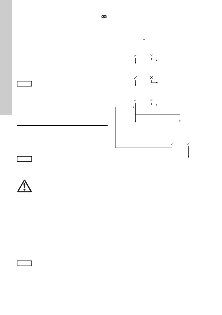
6.8 Pressure monit orin g
Caution
Caution
Caution
Plug in pressur e s enso r pl u g or se lec t
’Setup > FlowControl active’ me nu
Prompt:
’Activate FlowContr.?’
FlowControl not
activated
FlowControl active,
Sensor not calibrated.
Prompt:
’Sensor calibration?’
Prompt:
’Suction valv e re mo ve d? ’
Sensor not calibrated.
OK
Calibration error
Message:
’Sensor cal ib . OK
Current pressure: X bar’
Message:
’Sensor calib. failed!
’Repeat?’
Sensor not calibr ated .
English (GB)
FC/FCM control varian t.
A pressure se nsor monitors th e pr e ssu re in t he
dosing head. If the pressure during the discharge
phase falls below 2 bar, a warning is generated
(pump continues running). If in the ’Setup > Pressure
monitoring’ menu the func tio n ’ Min . pres sur e alarm’
is activated, an alarm is generated and the pump is
stopped.
If the pressure exceeds the cut-off pressure set in
the ’ Set up > Press ur e mo nit ori n g’ me nu, th e pu mp i s
shut down, ent er s the st a nd by st at e a nd i n dic at es an
alarm.
The pump restarts automatically once
the backpressure fal ls below the cut-of f
pressure!
6.8.1 Pressure setting ranges
4. Proceed as described below to calibrate:
Type
Fixed min.
pressure (bar)
DDA 7.5 - 16 < 2 3 ... 17
DDA 12-10 < 2 3 ... 11
DDA 17-7 < 2 3 ... 8
DDA 30-4 < 2 3 ... 5
The pressure measured in the dosing
head is slightly higher than the actual
system pressure.
Therefore the cut-off pressure should
be set min. 0.5 bar higher than the
system pressure.
6.8.2 Calibration of pressure sensor
The pressure sensor is calibrated in the factory. As a
rule, it does not need to be re-calibrated . If specific
circumstances (e. g. pressure senso r excha nge,
extreme air pressure values at the location of the
pump) necessitate a calibration, the sensor can be
calibrated as follows:
1. Set pump to ’Stop’ operational state.
2. Make system pressureless and flu sh.
3. Dis ma ntle suc tion line a nd s uct ion v alv e.
Warning
Install a pres su r e -re lie f valve in the
pressure line to provide protection
against impermissibly high pressure!
Calibrating w h en t h e su ct io n v al ve is
installed produ ces inc orrect calibr ation
and can cause personal injuries and
damage to property!
Only carry out a calibration if this is
technically r e qui re d !
Settable max.
pressure [bar]
If a calibration i s n ot su ccessfully possible, ch eck
plug connectio ns, cab le and se nsor an d repl ace
defective parts wher e necessa ry.
TM04 1145 2510
28
Page 29

6.9 Flow measurem ent
Note
Note
Note
FCM control variant
The pump accu r ate l y me as ur es the actual fl o w a nd
displays it. Via the 0/4 - 20 mA analog output, the
actual flow signal can easily be integrated into an
external process control without additional
measuring equipment (see section 6.5 Analog
output).
The flow measurement is based on the indicator
diagram as described in section 6.7 FlowCon trol.
The accumulated length of the discharge phase
multiplied by the stroke frequency produces the
displayed actual flow. Faults e. g. air bubbles or
backpressure that i s t oo lo w r esult in a smal ler or
larger actual flow. When the ’ AutoFlowAdapt’
function is activa ted (s ee secti on
6.10 AutoFlowAdapt), the pump compensates f or
these influences by correction of the stroke
frequency.
Strokes which canno t be an alys ed
(partial strokes, pressure differential
which is too lo w) a re p r ovis io n al ly
calculated b a se d o n th e s et po i nt v al ue
and displayed.
6.10 AutoFlowAdapt
FCM control variant.
The ’AutoFlowAdapt ’ fun ction is activate d in the
’Setup’ menu. It detects changes in various
parameters and responds accordingly in order to
keep the set target flow cons tant.
Dosing accuracy is increased when
’AutoFlowAdapt’ is activated.
This function processes information from the
pressure senso r in the do sing he ad. Err ors det ect ed
by the sensor are processed by the software. The
pump responds immediately regardless of the
operation mode by adjusting the stroke frequency or
where necessary compensating for the deviations
with a corres po nding indicator d i a gram .
If the target flow cannot be achieved by the
adjustments, a warning is issued.
’AutoFlowA da pt’ operates on the basis of the
following functions:
• FlowControl: malfunctions are identified (see
section 6.7 FlowContr ol).
• Pressure moni t or in g: pressu re fl uct ua ti o ns a re
identified (s ee s ect ion 6.8 Pressure monitoring).
• Flow measurement: deviations from the target
flow are identified (see section 6.8.2 C alibration
of pressure sensor).
Examples of ’AutoFlowAdapt’
Pressure fluctuations
The dosing volu me d ecr e ases as backpressure
increases and conversely the dosing volume
increases as the b ack pr es sur e de crea se s.
The ’AutoFlowAdapt’ function identifies p re ssur e
fluctuations and responds by adjusting the stroke
frequency. The actua l f l ow i s th us m ai n taine d at a
constant level.
Air bubbles
The ’AutoFlowAdapt’ function identifies a ir bu bb le s.
The pump responds with a special indicator diagram
due to which the air bubbles are removed as a top
priority (deaeration).
If the air bubbles have not been eliminated after a
maximum of 6 0 s tr ok es, th e pu m p swit che s to th e
’Air bubble’ warning status and returns to the norm al
indicator diagram.
6.11 Auto deaeration
Dosing degassing media can result in air
pockets in the d osi ng head during br ea ks in
dosing. This can result in no medium being dosed
when restarting the pump. The ’Setup > Auto
deaeration’ function performs pump deaeration
automatically a t re gu lar in te rv als . S o ftwa re controlled diaphragm movements encourage any
bubbles to rise and gather at the discharge valve so
that they can be r em o ve d o n th e ne xt do sin g str oke.
The function works:
• when the pump is not in the ’Stop’ mode
• during brea ks in dosin g (e. g. External stop, no
incoming pulses, etc. ).
Low volumes can be displaced into the
discharge line by the diaphragm
movements. W h en do sing strong ly
degassing media, this is however
virtually impos sib l e.
English (GB)
29
Page 30

6.12 Key lock
Operation
1.30
l/h
Manual
1.28 l/h
Additional display
English (GB)
The key lock is set in th e ’Setup > Key lock’
menu by ent eri ng a f ou r- di git code. It protects the
pump by preventing changes to settings. Two levels
of key lock can b e se lec te d:
Level Description
All settings can on ly be c hange d by
Settings
Settings +
keys
It is still possible to n avi gate in th e ’Alarm’ and ’I nf o’
main menu and reset alarms.
Temporary deactivation
If the key lock function is activated but settings need
to be modified, th e k eys c a n be un loc ke d tem por ar i l y
by entering the deactivation code. If the code is not
entered within 10 seconds, the display automatically
switches to the ’Operation’ main menu. The key lock
remains active.
Deactivation
The key lock can b e de ac tivated in the ’S et up > Key
lock’ menu via the ’Off’ menu point. The key lock is
deactivated after the general code ’2583’ or a predefined custom code has been entered.
entering the lock code.
The start/stop key and the 100 %
key are not locked.
The start/stop key and the 100 %
key and all settings are locke d.
6.13 Display Se tup
Use the followi ng se tt ing s in the ’Setup > Display’
menu to adjust th e display proper tie s:
• Units (metric/US)
• Display contrast
• A dditional dis play.
6.13.1 Units
Metric units (litres/millilitr es /bar ) or US units (U S
gallons/PSI) can be selected. According to the
operation mode and menu, the following units of
measurement ar e dis playe d:
Operation mode/
function
Manual contro l ml/h or l/h gph
Pulse control ml/ ml/
0/4-20 mA
Analogue control
Batch (pulse- or timer-
controlled)
Calibration ml ml
Volume counter l gal
Pressure monito ri ng bar psi
Metric units US units
ml/h or l/h gph
ml or l gal
6.13.2 Additional display
Additional display provides additional information
about the cu rr en t p um p s t at us . The v alu e i s sho wn i n
the display w ith th e co rr esponding sym bo l.
In ’Manual’ mode the ’Actual flow ’ information can be
displayed with Q = 1.28 l /h (se e fig. 3 4).
TM0 4 1151 111 0
Fig. 34 Display with ad dit i on al display
The additional display can be set as follows:
Setting D escription
Depending on the operation
mode:
Actual flow (manual, pulse)
Target flow (pulse)
Default display
Dosed volume
Actual flow Current actual flow
Backpressure
1)
only DDA-FCM control variant
2)
only DDA-FCM/FC control variant.
Input current (analog)
Remaining batch volume
(Batch, Dos. Timer)
Period until next dosing
(Dos. Timer)
Dosed vol. since las t reset
(see Counters on page 21)
Current back pr es sur e in th e
dosing head
2)
1)
1)
30
Page 31

6.14 Time/date
Caution
Bus
Bus control active
Bus address
127
In/Output
Relay 1
Relay 2
External stop
Empty signal
Low-level signal
>
>
NO
NO
NO
The time and date can be set in the ’Set up >
Time+date’ menu .
The conversion between summer and
winter time does not take place
automatically!
6.15 Bus commu nicati on
The pump is supplied with a n int eg rated
module for GENIbu s commun icatio n. The
pump identif ies the bus con tr ol afte r co nn ecting to
the corresponding signal input. The "Activate
Genibus?"prompt is displayed. After confirmation,
the ’Bus’ submenu appears in the ’Setup’ menu.
Fig. 35 ’Setup > Bus’ menu
The correspon d i ng sy mb ol ap pears in the ’Activated
functions’ area in the ’Operation’ menu.
The pump c an a lso be in tegrated into a Pr of i bu s D P
network using the additional E-box module
(retrofitting possib le) .
The bus communication enables remote monitoring
and setting of the pu mp vi a a fiel dbus sys tem. The
accompanyin g fiel dbus do cume ntatio n an d the
Profibus GSD file can be downloaded from the
Internet.
www.grundfosalldos.com
6.16 Inputs/outputs
In the ’Setup > In pu ts/o ut pu ts’ m enu, yo u ca n
configure the two outputs ’Relay 1+2’ and the signal
inputs ’External st op ’, ’E m pty si gn al ’ an d ’Low l evel
signal’.
Fig. 36 ’Setup > Inputs/out p uts’ me nu
6.16.1 Relay ou t p uts
The pump can switch two external signals using
installed relays. The relays are switched by potentialfree pulses. The connection diagram of the relays is
shown in sec tio n 4.3 Electrical connection. Both
relays can be allocate d with t he fo llowin g s ign als:
TM04 1139 2410
Relay 1
signal
Alarm* Alarm
Προειδοποί
ηση*
Stroke
signal
Pump
dosing
Bus control Bus control
Contact type
NO* NO* Normally open contact
NC NC
Relay 2
signal
Warning
Stroke
signal*
Pump
dosing
Timer, cycle see follo win g sec tio n
Timer, week see following sectio n
Description
Display red, pump
stopped (e. g. empty
signal, etc. )
Display yellow, pump is
running (e. g. low-level
signal, etc. )
each full stroke
Pump running and
dosing
Activated by a
command in the bus
communication
Normally closed
contact
English (GB)
TM04 1152 1110
* Factory setting
31
Page 32

Timer, cycl e (relay 2)
Caution
t
2
t
3
t
1
t
1
English (GB)
For the ’Relay 2 > Timer cycl e ’ function, set the
following param eter s:
•Dosing time (t
• Start delay (t
•Cycle time (t
)
1
)
2
)
3
Fig. 37 Diagram
Timer, week (relay 2)
This function saves up to 16 relay on-times for a
week. The following settings can be made for each
relay switching operation in the ’Relay 2 >
Timer Week’ menu:
• Procedure (No.)
• On-time (dur ation )
• Start time
• Weekdays.
6.16.2 External stop
The pump can be stopped via an external
pulse, e. g. from a control room. When activating the
external stop pulse, the pump switches from the
operational stat e ’ Ru nn in g’ in to th e ope ra tional state
’Standby’. The co rr es po nd i ng s ym bo l a pp ea rs i n th e
Signal/error di spla y (see se ction 6.2.2 Op er ating
states).
Frequent disengagement from the
mains voltage, e. g. via a relay, can
result in damage to the pump
electronics and to the breakdown of the
pump. The dosing accuracy is also
reduced as a re su l t o f i nt ern al start
procedures.
Do not control the pump via the mains
voltage for dosing purposes!
Only use the ’External stop’ func tion to
start and stop the pump!
The contact ty pe is fa cto r y-s et to closed contact
(=>NO). In the ’Setup > Inputs/outputs > External
stop’ menu, the setting can be changed to open
contact (=>NC).
6.16.3 Empty a n d lo w- le ve l si gn a ls
In order to monitor t he filling level in the
tank, a dual-level senso r can be connec ted to th e
pump. The pum p re sp on ds to the sign als as follows:
Sensor signa l Pump status
• Display is yellow
Low level
• flashes
• Pump continues
running
• Display is red
Empty
• flas hes
• Pump stops
Both signal i n pu ts ar e a l loc at ed to th e c los ed c ont ac t
(=>NO) in the f actory. They can be re- al located in
TM04 1124 2110
the ’Setup > In pu ts/ou tp uts’ menu to open contact
(=>NC).
6.17 Basic settin gs
All settings can be reset to the se tting s defau lt upon
delivery in the ’Setup > Basic set tings ’ menu.
Selecting ’Save customer settings’ saves the current
configuration to the memory. This can then be
activated using ’Load customer settings’ .
The memory alw ays contains the pr ev iou sl y sa ved
configuration. Older mem or y d a ta i s ov er w ri tte n.
32
Page 33

7. Service
Service soon!
Please exchan ge
diaphragm and valves!
Service kit:
97xxxxxx
Service now!
Please exchan ge
diaphragm and valves!
Service kit:
97xxxxxx
Caution
In order to ensure a long service life and
dosing accuracy, wearing parts such as
diaphragms and valves must be regularly checked
for signs of w ea r. Where ne ce ssa ry, replace worn
parts with original spare parts made from suitable
materials.
Should you have an y qu es tio ns, pl e as e co nta ct yo ur
service partner.
Warning
If the diaphragm leaks or is broken,
dosing liquid will escape from the
discharge opening on the dosing head
(see fig. 3).
Take suitable precautions to prevent
harm to health and damage to property
caused by escaping dosing liquid!
Check daily whether liquid is escaping
from the disch arg e ope nin g!
7.1 Service system
According to the motor runtime or after a defined
period of op e ra tio n, service req ui r em en ts wi l l
appear. Service requirements appear regardless of
the current operational state of the pump and do not
affect the dosing process.
Service requirement
’Service soon’ 7500 23
’Service now’ 8000 24
* Since the last service system reset
Motor
runtime
[h]*
Time interval
[months]*
The service requirement signals when the
replacement of wearing parts is due and displays the
number of the se rvi ce kit. Press the cli ck w he el to
temporarily hide the service prompt.
When the ’Service now’ message appears (displayed
daily), the pump must be serviced immediately. To
signalise in the ’Operation’ menu, the symbol
appears in the ’Signal/error display’ area of the
display.
The number of the service kit required is also
displayed in the ’Info’ menu.
For media whic h resul t in i nc reased wear, the service
interval must be sh or te ne d.
7.2 Perform service
Only spare parts and accesso ries f rom Grun dfos
should be used for maintenance. The usage of nonoriginal spare parts and accessories renders any
liability for resulting dama ges n ull and vo id.
Information about carrying out maintenance can be
found in the servic e kit catalog on our ho mepag e
(www.grundfosalldos.com).
Warning
When dosing dangerous media,
observe the cor responding p recautions
in the safety data sheets!
Risk of chemical burns!
Wear protective clothing (gloves and
goggles) when working on the dosing
head, connections or lines!
Do not allow any chemicals to leak
from the pump. Collect and dispose of
all chemical s co rr ec tl y!
Before any work to the pump, the pump
must be in the ’Stop’ operational state
or be disconnected from the mains.
The system must be pressureless!
English (GB)
Fig. 38 ’Service soon’
Fig. 39 ’Service now’
TM0 4 1131 111 0TM04 1131 1110
33
Page 34

7.2.1 Dosing head overview
123 57 8
46 10
9
Caution
English (GB)
Fig. 40 Changing the diap hr ag m an d va l ve s
1 Safety d iap hr ag m
2Flange
3O-ring
4 Diaphragm
5 Valve on discharge side
6 Valve on suction side
7 Dosing head
8 Screws with discs
9 Cover
10 Deaeration v alv e
7.2.2 Disma ntli ng th e diap hr agm an d valv es
1. Make system pressureless.
2. Empty dosing head before m ai n te na n ce an d
flush it if necessa ry.
3. Set pump to ’Stop’ operational state using the
’Start/stop key’.
4. Press the ’Start/stop’ and ’100 %’ keys at the
same time to put the diaphragm into ’out’
position.
– Symbol must b e di s pla ye d as the
operational stat e (s ee fi g . 14 ).
5. Take suitable s te ps to e ns ur e that the returning
liquid is safely collect ed.
6. Dismantle suction, pressure and deaeration
hose.
7. Dismantle valves on suction an d disc harg e
side (5, 6) .
8. Remove the cover (9).
9. Undo screws (8) on the dosing head (7) and
remove with d iscs .
10.Remove the dosing head (7).
11.Un scr ew diaphragm (4 ) co un te r- clo ckwise and
remove with fla n ge ( 2).
7.2.3 Reassembling the diaphragm and valves
1. Attach flange (2) correctly and screw on new
diaphragm (4) clockwise.
– Make sure that the O-ring (3) is seated
correctly!
2. Press the ’Start/stop’ and ’100%’ keys at the
same time to put the dia phr agm int o ’in’ position .
– Symbol must be displayed as the
operational state (see fig. 14).
3. Attach the dosing head ( 7) .
4. Install screws with discs (8) and cross-tighten.
– Torque: 3 Nm.
5. Attach the cover (9).
6. Install new valves (5, 6).
TM04 1123 2110
– Do not interchang e va l ve s an d pay attention to
direction of arrow.
7. C onnect suction, pressure and deaeration hose
(see section 4.2 Hydraulic connection)
8. Press the ’Start/Stop’ key to leave the service
mode.
9. Deaerate dosing pump (see sec tio n
5.2 Deaerating the pump).
10.Please observe t he n ot es on commissioning i n
section 5. Commissi oning!
7.3 Resetting the service system
After performing the ser vice, th e servic e system
must be reset u s ing t he ’Info > Reset service system’
function.
7.4 Repairs
Warning
The pump housing must only be
opened by personnel authorised by
Grundfos!
Repairs must only be carried out by
authorised and qualified personnel!
Switch off the pump and disconnect it
from the voltage supply before carry ing
out maintenance work and repairs!
After consultin g G r un df os, p l ea se se nd t he p um p,
together with th e safety declara tio n completed by a
specialist, to Grundfo s. The safe ty decla ration can
be found at the end of these instructions. It must be
copied, comple te d an d at tach ed to the pump.
If the above requirements are not met, Grundfos may
refuse to accept delivery of the pump. The shipping
costs will be charged to the sender.
If the pump has been used to dose
toxic liquids or liquids hazardous to
health, the pump must be cleaned prior
to dispatch !
34
Page 35

8. Faults
Alarm
12.02.2010
12.02.2010
1
Empty
2
Low level
12:34
12:34
Delete alarm
messages
❑
In the event of faults in the dosing pump, a
warning or an ala rm is trig ge red . The
corresponding fault symbol flashes in the
’Operation’ menu, see section 8.1 List of faults. T he
cursor jumps to the ’Alarm’ main menu symbol.
Press the click wheel to open the ’Alarm’ menu and,
where necessary, faults to be acknowled ged will b e
acknowledged.
A yellow display indicates a warning and the pump
continues runn ing.
A red display indicates an alarm and the pump is
stopped.
The last 10 faults are stored in the ’Alarm’ main
menu. When a new fault occurs, the oldest fault is
deleted.
The two most recent faults are shown in the display,
you can scroll through all the other faults. The time
and cause of the fault are displayed.
The list of faults can be delete d at the en d of the li st.
If there is a service requirement, this appears when
the ’Alarm’ menu is opened. Press the click wheel to
temporarily cl ose th e servic e prom pt (see sec tion
7.1 Serv ice sys te m ).
English (GB)
TM04 1109 1010
35
Page 36
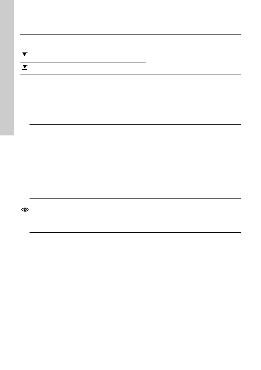
8.1 List of faults
English (GB)
8.1.1 Faults with error message
Display in the
’Alarm’ menu
Empty
(Alarm)
Low level
(Warning)
Overpressure
(Alarm)
Backpressure
low
(Warning/alarm*)
Air bubble
(Warning)
Cavitation
(Warning)
Suct. valve leak
(Warning)
Disch. va lve leak
(Warning)
Flow deviation
(Warning)
Possible cau s e Possible remedy
• Dosing medium tank empty • Fill tank.
• Dosing medium tank almost empty
• Discharge valve blocked
• Isolating valve in discharge line
closed
• Pressure peaks due to high
viscosity
• ’Max. pressure ’ s et too low (see
section 6.8 Pressure m o nit or i ng )
• Faulty diaphr agm
• Broken discha rge line
• Pressure differential between
suction and discha rge sid e too low
• Leakage in the pressure retention
valve at Q < 1 l/h
• Deaeratio n valve op en
• Broken/leaky suction lin e
• Strongly degassing medium
• Tank dosing medium empty
• Blocked/con str ict ed /squeezed
suction line
• Blocked/constr ict ed s uct ion v alve
• Suction lift too hig h
• Viscosity too high
• Leaky/dirty suction valve
• Deaeratio n valve op en
• Leaky/dirty discharge valve
• Leakage in the pressure retention
valve
• Deaeratio n valve op en
• Considerable deviation between
target and actual flow
•
Pump not / inco rr e ctly ca lib ra te d
• Check contact sett ing ( NO/ NC)
• Replace valv e if n ecessary (see se ction
7.2 Perform service)
• Check flow direction of valves (arrow) and
correct if necessary.
• Open the isolating valve (on the discharge
side).
• Enlarge diameter of discharge line.
• Change pres sur e se tting (see sect ion
6.8 Pressure monitoring).
• Change the diaphragm (see section
7.2 Perform service).
• Check discharg e lin e and re pair if
necessary.
• Install additio na l spring-loade d va lv e
(approx. 3 bar) on the discharge side.
• Close the deaeration valve.
• Check suction line and repair if necessary.
• Provide positive inlet pressure (place
dosing medium tank above the pump).
• Enable ’Slow Mode’ (see section
6.6 SlowM ode).
• Fill tank.
• Enable 'Slow Mode’ (see section
6.6 SlowM ode).
• Reduce suct io n lift.
• Increase suction hose diameter.
• Check suction line and open isolating
valve if necessary.
• Check valve and tig hten it up.
• Flush system.
• Replace valv e if n ecessary (see se ction
7.2 Perform service).
• Check O-ring posit ion .
• Install filter in suction line.
• Close the deaeration valve.
• Check valve and tig hten it up.
• Flush system.
• Replace valv e if n ecessary (see se ction
7.2 Perform service).
• Check O-ring posit ion .
• Install screen in suction li ne.
• Close the deaeration valve.
• Install spring -lo ad e d v al v e on th e
discharge side.
• Check installation.
• Calibrate the pump (see section
5.3 Calibrating the pump).
36
Page 37

Display in the
’Alarm’ menu
Pressure sensor
(Warning)
Motor blocked
(alarm)
Bus
(Warning/alarm*)
E-Box
(Alarm)
Cable break
(Alarm)
Service soon/
now
(Warning)
* Depending on setting
Possible cau s e Possible remedy
• Broken FlowControl cable
• Sensor defect
• Pressure sensor not correctly
calibrated.
• Check plug connect ion.
• Change sensor if ne cessa ry.
• Calibrate pressure sensor correctly
(see section 6.8.2 Calibration of p re ssu re
sensor).
• Backpressure greater than
nominal pressur e
• Reduce backpressure.
• Arrange for repair of gears, if necessary.
• Damage to gears
• Fieldbus communica tion er ror • C heck cable s for corre ct specif icatio n and
damage; replace if necessary.
• Check cable rou ting and shielding ; co rr ect
if necessary.
• E-Box connection error
• Faulty E-Box
• Defect in analog cable 4 - 20 mA
(input current < 2 m A)
• Check plug connect ion.
• Replace E-Box if n ece ss ar y.
• Check cable/plug connections and
replace, if necessary.
• Check signal transmitter.
• Time interval for service expired • Perform service (see section 7.2 Perform
service).
English (GB)
37
Page 38

8.1.2 General faults
Subject to alte ra tio ns .
English (GB)
Fault Possible cause Possible remedy
Install addition a l sp ri n g -lo ad ed valve
(approx. 3 b ar) on the disch ar ge s ide .
Increase pressu re d iffer en tia l.
Calibrate the pump (see section 5.3 Calibra ti n g
the pump).
Change the d iap hr ag m ( s ee s ect ion 7.2 Perform
service).
Check that the arrow on the valve housing is
pointing in th e di r ecti o n of flo w. Check whether all
O-rings are installed correctly.
Reduce suction lift.
Install priming aid.
Enable 'Slow Mode’ (see section 6.6 SlowMode).
Enable 'Slow Mode’ (see section 6.6 SlowMode).
Use hose with larger diameter.
Install spring-loaded valve on the discharge side.
Calibrate the pump (see section 5.3 Calibra ti n g
the pump).
Tighten up valves, replace valves if necessary
(see section 7.2 Perform service).
Keep backpress ur e co nsta nt.
’AutoFlowAdapt’ activate (only FCM).
Change the d iap hr ag m ( s ee s ect ion 7.2 Perform
service).
Tighten up screws (see se ctio n 4.2 Hydraulic
connection).
Tighten up valves/u nion nuts (see section
4.2 Hydraulic connection).
Reduce suction lift; if necessa ry, provide positive
inlet pressure.
Flush system, re pl a ce va lv e s if n ec essary
(see section 7.2 Perform service).
Dosing flow too high
No dosing flow or
dosing flow too low
Irregular dosing
Liquid escaping from
the dischar ge opening
on the flange
Liquid escaping
Pump not sucking in
Inlet pressur e gr e ate r th an
backpressure
Incorrect calibration
Air in dosing head Deaerate the pump.
Faulty diaphragm
Leakage/fra ctu r e i n lines Check and repair line s.
Valves leaking or blocked Check and clean valves.
Valves installed incorrectly
Blocked suction line Clean suction line/install filter.
Suction lift too high
Viscosity too high
Pump outside the cal ibrat ion
Deaeration valve open Close the deaeration valve.
Valves leaking or blocked
Backpressure flu ctuat ions
Faulty diaphragm
Dosing head screws not
screwed in as far as th ey will go
Valves not screwed in as far as
they will go
Suction lift too high
Backpressure to o high Open the deaerat ion valve.
Soiled valves
9. Disposal
This product and all its associated parts must
be disposed of in an environmentally friendly
manner. Use appropriat e was te col lecti on
services. If there is no such f aci lity or t he fa cilit y
refuses to accept thse materials used in the product,
the product can be sent to the nearest Grundfos
company or Grun dfos service ce ntre.
38
Page 39

Appendix 1
100%
Safety decla ration
Please copy, fill in and sign this sheet and attach it to the pump returned for service.
Product type (nameplate)
Model number (nameplate)
Dosing medium
Fault description
Please make a circle around the damaged parts.
In the case of an e lectrical or fun ct i on al fa ul t , p le ase m a rk th e cabinet.
Please descri b e the e rr o r / c au s e of th e er r or in b rie f.
Appendix
TM04 1185 1110
We hereby declare that the pump has been cleaned and is completely free from chemical, biological and
radioactive substa nc es.
_____________________________________
Date and si gn at ur e
_____________________________________
Company stamp
39
Page 40

40
Page 41

41
Page 42

Argentina
Grundfos companies
Bombas GRUNDFOS de
Argentina S.A.
Ruta Panamericana km. 37.500
Lote 34A
1619 - Garin
Pcia. de Buenos Aires
Phone: +54-3327 414 44 4
Telefax: +54-3327 411 111
Australia
GRUNDFOS Pumps Pty. Ltd.
P.O. Box 2040
Regency Park
South Australia 5942
Phone: +61-8-8461-4 611
Telefax: +61-8-8340 0155
Austria
GRUNDFOS Pumpen Vertrieb
Ges.m.b.H.
Grundfosstraße 2
A-5082 Grödig /S alz burg
Tel.: +43-6246-883-0
Telefax: +43-6246-883-30
Belgium
N.V. GRUNDFOS Bellux S.A.
Boomsesteenwe g 81-83
B-2630 Aartselaar
Tél.: +32-3-870 7300
Télécopie: +32-3-870 7301
Belorussia
Представительств о
ГРУНДФОС в Минске
220123, Минск,
ул. В. Хоружей, 22, оф. 1105
Тел.: +(37517) 233 97 65
Факс: (37517) 233 9769
E-mail:
grundfos_minsk@ mail. ru
Bosnia/Herzegovina
GRUNDFOS Sarajevo
Trg Heroja 16,
BiH-71000 Sarajevo
Phone: +387 33 713 290
Telefax: +387 33 659 079
e-mail: grundfos@bih. net.ba
Brazil
BOMBAS GRUNDFOS DO
BRASIL
Av. Humberto de Alencar
Castelo Branco, 630
CEP 09850 - 300
São Bernardo do Camp o - SP
Phone: +55-11 4393 5533
Telefax: +55-11 4343 5015
Bulgaria
Grundfos Bulgaria EO OD
Slatina District
Iztochna Ta ngenta street no.
100
BG - 1592 Sofia
Tel. +359 2 49 22 200
Fax. +359 2 49 22 201
email: bulgaria@grundfos.bg
Canada
GRUNDFOS Canada Inc.
2941 Brighton Road
Oakville, Ontario
L6H 6C9
Phone: +1-905 829 9533
Telefax: +1-905 829 9512
China
Grundfos Alldos
Dosing & Disinfection
ALLDOS (Shanghai) Water
Technology Co. Ltd.
West Unit, 1 Floor, No. 2
Building (T 4-2)
278 Jinhu Road, Jin Qiao
Export Processing Zon e
Pudong New A r ea
Shanghai, 201206
Phone: +86 21 5055 1012
Telefax: +86 21 5032 0596
E-mail: grundfosalldosCN@grundfos.com
China
GRUNDFOS Pumps
(Shanghai) Co. Ltd.
22 Floor, Xin Hua Lian Building
755-775 Huai Hai Rd, (M )
Shanghai 200020
PRC
Phone: +86-512-67 61 11 80
Telefax: +86-512-67 61 81 67
Croatia
GRUNDFOS CROATIA d.o.o.
Cebini 37, Buzin
HR-10010 Zagreb
Phone: +385 1 6595 400
Telefax: +385 1 6595 499
www.grundfos.hr
Czech Republic
GRUNDFOS s.r.o.
Čapkovského 21
779 00 Olomouc
Phone: +420-585-716 111
Telefax: +420-585-716 299
Denmark
GRUNDFOS DK A/S
Martin Bachs Vej 3
DK-8850 Bjerringbro
Tlf.: +45-87 50 50 50
Telefax: +45-87 50 51 51
E-mail:
info_GDK@grundfos.com
www.grundfos.com/DK
Estonia
GRUNDFOS Pumps Eesti OÜ
Peterburi tee 92G
11415 Tallinn
Tel: + 372 606 1690
Fax: + 372 606 1691
Finland
OY GRUNDFOS Pumput AB
Mestarintie 11
FIN-01730 Vantaa
Phone: +358-3066 5650
Telefax: +358-3066 56550
France
Pompes GRUNDFOS
Distribution S.A.
Parc d’Activités de Chesnes
57, rue de Ma lac om be
F-38290 St. Quentin Fallavier
(Lyon)
Tél.: +33-4 74 82 15 15
Télécopie: +33-4 74 94 10 51
Germany
GRUNDFOS Water Treatment
GmbH
Reetzstraße 85
D-76327 Pfinztal (Söllinge n)
Tel.: +49 7240 61-0
Telefax: +49 7240 61-177
E-mail: gwt@grundfo s.com
Germany
GRUNDFOS GMBH
Schlüterstr. 33
D-40699 Erkrath
Tel.: +49-(0) 211 929 69-0
Telefax: +49-(0) 211 929 693799
E-mail:
infoservice@grundf os.d e
Service in Deutschland:
E-mail:
kundendienst@gru ndfos .de
Greece
GRUNDFOS Hellas A.E.B.E.
20th km. Athinon-M arkopoulou
Av.
P.O. Box 71
GR-19002 Peania
Phone: +0030-210-66 83 400
Telefax: +0030-210-66 46 273
Hong Kong
GRUNDFOS Pumps (Hong
Kong) Ltd.
Unit 1, Ground f loor
Siu Wai Industrial Centre
29-33 Wing Hong Street &
68 King Lam Street, Cheung
Sha Wan
Kowloon
Phone: +852-27861706 /
27861741
Telefax: +852-27858664
Hungary
GRUNDFOS Hungária Kft.
Park u. 8
H-2045 Törökbálint,
Phone: +36-23 511 110
Telefax: +36-23 511 111
India
GRUNDFOS Pumps India
Private Limited
118 Old Mahabalipuram Road
Thoraipakkam
Chennai 600 096
Phone: +91-44 2496 6800
Indonesia
PT GRUNDFOS Pompa
Jl. Rawa Sumur III, Blok III /
CC-1
Kawasan Industri, Pulogadung
Jakarta 13930
Phone: +62-21-460 6909
Telefax: +62-21-460 6910 / 460
6901
Ireland
GRUNDFOS (Ireland) Ltd.
Unit A, Merrywell Business
Park
Ballymount Road Lower
Dublin 12
Phone: +353-1-4089 800
Telefax: +353-1-4089 830
Italy
GRUNDFOS Pompe Italia S.r .l .
Via Gran Sasso 4
I-20060 Truccazzano (Milano)
Tel.: +39-02-95838112
Telefax: +39-02-95309290 /
95838461
Japan
GRUNDFOS Pumps K.K.
Gotanda Metalion Bldg. 5F,
5-21-15, Higashi-gota nda
Shiagawa-ku, Tokyo,
141-0022 Japan
Phone: +81 35 448 1391
Telefax: +81 35 448 9619
Korea
GRUNDFOS Pumps Korea Ltd.
6th Floor, Aju Building 679-5
Yeoksam-dong, Kangnam-ku,
135-916
Seoul, Korea
Phone: +82-2-5317 600
Telefax: +82-2-5633 725
Latvia
SIA GRUNDFOS Pumps Latvia
Deglava biznesa centrs
Augusta Deglava ielā 60, LV-
1035, Rīga,
Tālr.: + 371 714 9640, 7 149
641
Fakss: + 371 914 9646
Lithuania
GRUNDFOS Pumps UAB
Smolensko g. 6
LT-03201 Vilnius
Tel: + 370 52 395 430
Fax: + 370 52 395 431
Malaysia
GRUNDFOS Pumps Sdn. Bhd.
7 Jalan Peguam U1/25
Glenmarie Industrial Park
40150 Shah Ala m
Selangor
Phone: +60-3-5569 2922
Telefax: +60-3-5569 2866
México
Bombas GRUNDFOS de
México S.A. de C.V.
Boulevard TLC No. 15
Parque Industrial Stiva
Aeropuerto
Apodaca, N.L. 66600
Phone: +52-81-8144 4000
Telefax: +52-81-8144 4010
Netherlands
GRUNDFOS Netherlands
Veluwezoom 35
1326 AE Almere
Postbus 22015
1302 CA ALMERE
Tel.: +31-88-478 6336
Telefax: +31-88-478 6332
E-mail: info_gnl@grundfos.com
New Zealand
GRUNDFOS Pumps NZ Ltd.
17 Beatrice Tinsley Crescent
North Harbour Industrial Esta te
Albany, Auckland
Phone: +64-9-415 3240
Telefax: +64-9-415 3250
Norway
GRUNDFOS Pumper A/S
Strømsveien 344
Postboks 235, Leirdal
N-1011 Oslo
Tlf.: +47-22 90 47 00
Telefax: +47-22 32 21 50
Page 43

Poland
GRUNDFOS Pompy Sp. z o.o.
ul. Klonowa 23
Baranowo k. Poznania
PL-62-081 Przeźmierowo
Tel: (+48-61) 650 13 00
Fax: (+48-61) 650 13 50
Portugal
Bombas GRUNDFOS Portugal,
S.A.
Rua Calvet de Magalh ães, 241
Apartado 1079
P-2770-153 Paço de Arcos
Tel.: +351-21-440 76 00
Telefax: +351-21-440 76 90
România
GRUNDFOS Pompe România
SRL
Bd. Biruintei, nr 103
Pantelimon county Ilfov
Phone: +40 21 200 4100
Telefax: +40 21 200 4101
E-mail: romania@gr undfo s.ro
Russia
ООО Грун дф ос
Россия, 109544 Москва, ул.
Школьная 39
Тел. (+7) 495 737 30 00, 564
88 00
Факс (+7) 495 737 75 36, 564
88 11
E-mail
grundfos.moscow @g run df os.c
om
Serbia
GRUNDFOS Predstavništvo
Beograd
Dr. Milutina Ivkovića 2a/29
YU-11000 Beograd
Phone: +381 11 26 47 877 / 11
26 47 496
Telefax: +381 11 26 48 340
Singapore
GRUNDFOS (Singapore) Pte.
Ltd.
24 Tuas West Road
Jurong Town
Singapore 638381
Phone: +65-6865 1222
Telefax: +65-6861 8402
Slovenia
GRUNDFOS d.o.o.
Šlandrova 8b, S I -1231
Ljubljana-Črn uče
Phone: +386 1 568 0610
Telefax: +386 1 568 0619
E-mail: slovenia@grundfos.si
South Africa
Grundfos (PTY) Ltd.
Corner Mountjoy and George
Allen Roads
Wilbart Ext. 2
Bedfordview 2008
Phone: (+27) 11 579 4800
Fax: (+27) 11 455 6066
E-mail: lsmart@grundfos.com
Spain
Bombas GRUNDFOS España
S.A.
Camino de la Fuentecilla, s/n
E-28110 Algete (Madrid)
Tel.: +34-91-848 8800
Telefax: +34-91-628 0465
Sweden
GRUNDFOS AB
(Box 333) Lunnagårds gatan 6
431 24 Mölndal
Tel.: +46(0)771-32 23 00
Telefax: +46(0)31-331 94 60
Switzerland
GRUNDFOS ALLDOS
International AG
Schönmattstraße 4
CH-4153 Reinach
Tel.: +41-61-717 5555
Telefax: +41-61-717 5500
E-mail: grundfosalldosCH@grundfos.com
Switzerland
GRUNDFOS Pumpen AG
Bruggacherstrasse 10
CH-8117 Fällanden/ZH
Tel.: +41-1-806 8111
Telefax: +41-1-806 8115
Taiwan
GRUNDFOS Pumps (Taiwan)
Ltd.
7 Floor, 219 Min-Chuan Road
Tai chu ng, Ta iwan , R.O . C.
Phone: +886-4-2305 0868
Telefax: +886-4-2305 0878
Thailand
GRUNDFOS (Thailand) Ltd.
92 Chaloem Phrakiat Rama 9
Road,
Dokmai, Pravej, Bangkok
10250
Phone: +66-2-725 8999
Telefax: +66-2-725 8998
Turkey
GRUNDFOS POMPA San. ve
Tic. Ltd. Sti.
Gebze Organize Sanayi Bölgesi
Ihsan dede Caddesi,
2. yol 200. Sokak No. 204
41490 Gebze/ Kocaeli
Phone: +90 - 262-679 7979
Telefax: +90 - 262-679 7905
E-mail: satis@grundfos.com
Ukraine
ТОВ ГРУНДФОС УКРАЇНА
01010 Київ, Вул. Московська
8б,
Тел.:(+38 044) 390 40 50
Фах.: (+38 044) 390 40 59
E-mail: ukraine@grundfos.com
United Arab Emirates
GRUNDFOS Gulf Distribution
P.O. Box 16768
Jebel Ali Free Zone
Dubai
Phone: +971-4- 8815 166
Telefax: +971-4-8815 136
United Kingdom
GRUNDFOS Pumps Ltd.
Grovebury Road
Leighton Buzzard/Beds. LU7
8TL
Phone: +44-1525-850000
Telefax: +44-1525-850011
U.S.A.
GRUNDFOS Pumps
Corporation
17100 West 118th Terrace
Olathe, Kansas 66061
Phone: +1-913-227-3400
Telefax: +1-913-227-3500
Usbekistan
Представительство
ГРУНДФОС в Ташк енте
700000 Таш кен т ул.Ус мана
Носира 1-й
тупик 5
Теле фо н: (37 12) 55-68 -15
Факс: (3712) 53-36-35
Grundfos companies
Addresses revised 03.11.2010
Page 44
Being responsible is our foundation
Thinking ahead makes it possible
Innovation is the essence
15.720310 V1.0
95724708 1110
ECM: 1065172
The name Grundfos, the Grundfos logo, and the payoff Be–Think–Innovate are registrated trademarks
owned by Grundfos Management A/S or Grundfos A/S, Denmark. All rights reserved worldwide.
www.grundfosalldos.com
GB
 Loading...