

Grundfos SL1.40.A60 82, SL1.20.A30.30, SL1.20.A30.40, SLV.25.A25 88, SLV.25.A30 94 Product Manual
...Page 1
GRUNDFOS PRODUCT GUIDE
SL1, SLV pumps
1.5 to 15 hp
60 Hz
Page 2

Contents
Introduction
Introduction 3
Applications 3
Overall construction features 3
Performance range
Performance range, SL1, SLV pumps 4
Identification
Type key 5
Nameplate 6
Selection of product
Ordering a pump 7
Product range
SL1 pump range 8
SLV pump range 11
Variants
List of variants 15
Performance curves
Technical data
SL1.20.A25 40
SL1.20.A30 46
SL1.30.A30 52
SL1.30.A40 64
SL1.40.A40 76
SL1.40.A60 82
SLV.25.A25 88
SLV.25.A30 94
SLV.30.A30 100
SLV.30.A40 120
SLV.40.A40 140
Accessories
Installati on systems 148
Other accessories 149
Level controllers 150
Further product documentation
WebCAPS 152
WinCAPS 153
Construction
SL1 16
SLV 22
Components and material specification 28
Product description
Features 29
Operating condition s 30
Motor range 30
Pump controllers 31
Variable frequency drive operation 32
Wiring diagrams 33
Curve charts and technical data
How to read the curve charts 38
Curve conditions 39
Performance tests 39
Certificates 39
Witness test 39
2
Page 3

Introduction
SLV
SL1
Introduction
This data booklet deals with Grundfos submersible
sewage pumps, types SL1 and SLV.
Fig. 1 SL1 and SLV pumps
The pumps are free-flow (SuperVo rte x) and single channel impeller pumps specifically designed for
pumping sewage and wastewater in a w ide range of
municipal, private and industrial applications.
The pumps are made of resistant ma teri als, such as
cast iron and stainless steel. These materials ensure a
proper operation.
The pumps are fitted with motors fro m 1.5 hp up to
15 hp (1.1 to 11 kW). The motors are either 2- or 4-pole
motors, depending on the motor size.
The free passage in the pumps is 2 to 4” (50 to
100 mm).
The pumps are available for:
• submerged installation on auto-coupling system
• submerged installation, free-standing.
Applications
Typical applications are transfer of liquids, such as:
• municipal wastewater
• wastewater with high content of fibres (SuperVortex
impeller)
• drainage and groundwater
• domestic wastewater
• industrial wastewater
• process and cooling water.
The pumps are ideal for the pumping of the above
liquids from for instance:
• municipal network pumping stations
• inlet pumping stations in wastewater treatment
plants
• primary clarification in wastewater treatmen t pl ants
• secondary clarification in wastewater treatment
plants
• stormwater pumping stations
• public buildings
• residential buildings
• factories/industry.
Overall construction features
• Cable entry as cable plug, made of corrosionresistant stainless steel with conductors embedded
in polyamide
• Power cable incorporating wires for thermal sensors
in the motor windings
• No extra cable required for sensors in pumps with
sensors
• Monitoring of operating conditions for pumps with
sensors
• Moisture detector for continuous monitoring of
motor enclosure and automatic cut-out in case o f
leakage
• Heavy-duty bearings greased for life
• Built for variable frequency drive oper ation
• Smooth pump surface prevents dirt and impurities
from sticking to the pump
• Self-cleaning channel impeller with long vanes, thus
reducing risk of jamming or clogging, or Sup erVortex impeller with high pumping efficiency and
less downtime
• Explosion-proof motors for potentially explo sive
environments
• Motor in insulation class H (356 °F (180 °C ),
enclosure class IP68 with thermal sensor in each
phase
• Temperature rise class A (1.5 to 8 hp) or class B (10
to 15 hp)
• Service-friendly design:
- clamp connection between motor and pump
- cartridge shaft seal
- cable connection to motor via plug.
• Motor built of highly efficient EFF1 components,
offering lower motor temperature and longer life.
3
Page 4
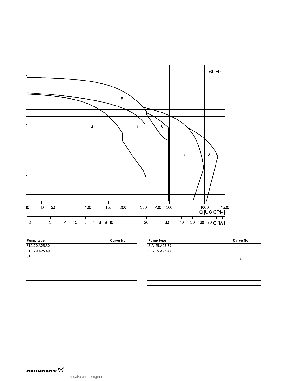
Performance range
Q [US GPM]
2 3 4 5 6 7 8 9 1010 20 30 40 50 60 70
Q [l/s]
60 Hz
1
2
4
5
6
3
Performance range, SL1, SLV pumps
Pump type Curve No Pump type Curve No
SL1.20.A25.30
SL1.20.A25.40 SLV.25.A25.40
SL1.20.A25.55 SLV.25.A25.55
SL1.20.A30.30 SLV.25.A30.30
SL1.20.A30.40 SLV.25.A30.40
SL1.20.A30.55 SLV.25.A30.55
SL1.30 2 SLV.30 5
SL1.40 3 SLV.40 6
1
SLV.25.A25.30
4
TM04 7578 2210
4
Page 5
Identification
Type key
SL1, SLV
Code Example SL 1 30. A30. 55. A. Ex. 4. 6. 0H A. Q.
Pump type:
SL
Grundfos w ast ew ate r pu mp/sewage pump
Impeller type:
1
Single-channel impeller
V
Free-flow impeller (SuperVortex)
Pump passage. C ode number from type key / 10 [inch]:
20
2" (50 mm)
25
2.5" (65 mm)
30
3" (80 mm)
40
4" (100 mm)
Pump discharge (discharge port in inches):
A25
ANSI 2.5" (DN65)
A30
ANSI 3" (DN80)
A40
ANSI 4" (DN100)
A60
ANSI 6" (DN150)
Motor power. Code number from t yp e key / 10 [ hp ]
55
5.5 hp = 4.0 kW
Accessories:
[-]
Standard
A
Sensor
Pump version:
[-]
Non-explosion-proof
Ex
Explosion- pr oo f
Number of poles:
2
2-pole
4
4-pole
Frequency:
6
60 Hz
Voltage and starting method:
0J
3 x 208-230 V Δ DOL
1J
3 x 208-230 V Δ / 460V Y
1H
3 x 460V Δ Y/D
0L
3 x 575V Δ DOL
1L
3 x 575V Δ Y/D
Product generation:
A
1st generation
B
2nd generation
C
3rd generation
Material variant:
[-]
Cast iron impeller, volute and moto r housi ng
Q
Stainless steel impeller
Note: The pump types are not available in all variants.
5
Page 6

Identification
E
4
3
1
2
5
6
8
9
12
7
13
10
15
17
14
18
19
22
16
21
23
20
24
11
Nameplate
Fig. 2 Nameplate
Pos. Description
1 Protection according to FM
2 Type designation
3 Serial number
4 Production code (year/month)
5 Maximum ambient temperature
6 Maxi m um h ea d
7 Maxi m um fl ow rate
8 Rated input/output power
9 Rated voltage, D
10 Rated voltage, Y
11 Frequenc y
12 Country of production
13 CSA mark
14 FM mark
15 Enclosure class to IEC
16 Maximum installation depth
17 Po wer fa ctor
18 Number of phases
19 Rated speed
20 Service factor
21 Full load current, D
22 Full load current, Y
23 Insulation class
24 Weight without cable
TM04 4187 0909
6
Page 7
Selection of product
Ordering a pump
When ordering a pump, you need to take the following
five aspects into consideration:
1. pump type
2. custom-built variation (option)
3. explosion-proof version
4. accessories
5. pump controller.
Pump
Use the following table to ident ify w hich type of pu mp
that best meets your needs. The table is f or g uidance
only.
Application SL1 SLV
Storm water x x
Groundwater x x
Drainage and surface water x x
Drainage and surface water with small impurities x x
Abrasive surface water x x
Wastewater with long fibres, e.g. from laundries x x
Domestic wastew a ter w ith discharge from to ilets x x
Municipal sewage x x
Sewage from commercial buildings x x
Industrial pr oces s water w ith fibr es /solid s x
Industrial pr oces s wate r with s olids x x
Industrial process water without solids and fibres x
When you have selected the pump type, you can
identify the specific pump that best meets your needs in
section Product range on page 8 a nd T ype key on
page 5. The list below is a detaile d descr iptio n of the
product you get if you order the follo wing pump:
Custom-built variants
The pumps can be customized to meet individual
requirements. Many pump features and o ption s are
available for customization, such as explosion-proof
versions, various cable lengths or special materials.
Variants can be seen in the table in sect ion List of
variants on page 15. For requir ements or d esigns
outside the mentioned table, contact Grundf os.
Accessories
Depending on the installation type, accessories may be
required. See section Installation systems on page 148
for selection of the correct accessor ies.
Note: Ordered accessories are not fitted from factory.
Controller
The following controllers a re available:
• CU361 - Grundfos Dedicated Controls
Grundfos Dedicated Controls is a control system
designed for installation in either commercial buildings
or network pumping stations with one to six pumps.
Advanced control and data communication ar e al so
possible with the Grundfos Dedicated Controls system.
The Dedicated Controls system is desig ned to cont rol
and monitor Grundfos wastewater pumps.
See also section Pump controllers on page 31.
Explosion-proof version
The entire range is available in exp losion-proof
versions.
The SL1 and SLV pumps have the foll owing explosi on
protection classification: Class I, Division 1, Groups C
and D, T4, T3, IP68.
Pump Product no
SLV.25.A25.30.2.61H 96970895
• Pump as specified in the type key
• 33 ft (10 m) cable
• Paint: NSC 8005-R80B (dark gr ey), gloss co de 35,
thickness 100 μ
• Thermal switch in stator
• Tested according to Hydraulic Institute Centrifugal
pump test 1.6-2000 acceptance level B.
See section Performance curves Technical data for
selection of a standard pump.
Note: Product-specific dat a fo r the pu mp can a lso be
found in WebCAPS using the pr oduct number
96970895.
7
Page 8

Product range
SL1 pump range
Pump type Sensor
SL1.20.A25.30
SL1.20.A25.40
SL1.20.A25.55
SL1.20.A30.30
SL1.20.A30.40
SL1.20.A30.55
SL1.30.A30.20
SL1.30.A30.30
Single channel Q versions will be available from 3rd quarter of 2011. Contact Grundfos for more information.
Explosio n
proof
[.A] [.EX ] [.2] [.6 ] [0J] [1J] [1H] [0L] [1L] [.Q]
No No 2 6 - 96970713 96970715 - 96970716 No
Yes No 2 6 - 96971178 96971180 - 96971181 No
No Yes 2 6 - 96971644 96971646 - 969716 47 No
Yes Yes 2 6 - 96972111 96972113 - 96 972114 No
NoNo26-----Yes
YesNo26-----Yes
No No 2 6 - 96970719 96970724 - 96970722 No
Yes No 2 6 - 96971184 96971189 - 96971187 No
No Yes 2 6 - 96971650 96971655 - 969716 53 No
Yes Yes 2 6 - 96972117 96972122 - 96972120 No
NoNo26-----Yes
YesNo26-----Yes
No No 2 6 - 96970727 96970732 - 96970730 No
Yes No 2 6 - 96971192 96971197 - 96971195 No
No Yes 2 6 - 96971658 96971663 - 969716 61 No
Yes Yes 2 6 - 96972125 96972130 - 96972128 No
NoNo26-----Yes
YesNo26-----Yes
No No 2 6 - 96970735 96970737 - 96970738 No
Yes No 2 6 - 96971200 9697 12 02 - 9 69 71203 No
No Yes 2 6 - 96971666 96971668 - 969716 69 No
Yes Yes 2 6 - 96972133 96972135 - 96972136 No
NoNo26-----Yes
YesNo26-----Yes
No No 2 6 - 96970741 96970746 - 96970744 No
Yes No 2 6 - 96971206 96971211 - 96971209 No
No Yes 2 6 - 96971672 96971677 - 969716 75 No
Yes Yes 2 6 - 96972139 96972144 - 96972142 No
NoNo26-----Yes
YesNo26-----Yes
No No 2 6 - 96970749 96970754 - 96970752 No
Yes No 2 6 - 96971214 9697 12 19 - 9 69 71217 No
No Yes 2 6 - 96971680 96971685 - 969716 83 No
Yes Yes 2 6 - 96972147 96972152 - 97622851 No
NoNo26-----Yes
YesNo26-----Yes
No No 4 6 96970757 96970765 - 96970760 96970762 No
Yes No 4 6 96971222 96971230 - 96971225 96971227 No
No Yes 4 6 96971688 96971696 - 96971691 96971693 No
Yes Yes 4 6 96972155 96972163 - 96972158 96972160 No
No No 4 6 97662094 97662095 - 97661961 97661962 Yes
Yes No 4 6 97662139 97662140 - 97662005 97662006 Yes
No No 4 6 - 96970763 96970759 - 96970766 No
Yes No 4 6 - 96971228 9697 12 24 - 9 69 71231 No
No Yes 4 6 - 96971694 96971690 - 969716 97 No
Yes Yes 4 6 - 96972161 96972157 - 96972164 No
No No 4 6 - 97662096 97662101 - 97661963 Yes
Yes No 4 6 - 97662151 97662156 - 97662007 Yes
Poles Hz
3x208-230V
DOL
3x208-230V Δ
/ 460V Y
Voltage
3x460V Y/D 3x575V DOL 3x575V Y/D
Stainless steel
impeller
8
Page 9

Product range
Pump type Sensor
SL1.30.A30.40
SL1.30.A30.55
SL1.30.A30.75
SL1.30.A30.100
SL1.30.A40.20
SL1.30.A40.30
SL1.30.A40.40
SL1.30.A40.55
Single channel Q versions will be available from 3rd quarter of 2011. Contact Grundfos for more information.
Explosio n
proof
[.A] [.EX ] [.2] [.6 ] [0J] [1J] [1H] [0L] [1L] [.Q]
No No 4 6 - 96970769 96970774 - 96970772 No
Yes No 4 6 - 96971234 9697 12 39 - 9 69 71237 No
No Yes 4 6 - 96971700 96971705 - 969717 03 No
Yes Yes 4 6 - 96972167 96972172 - 96972170 No
No No 4 6 - 97662097 97662102 - 97661964 Yes
Yes No 4 6 - 97662152 97662157 - 97662008 Yes
No No 4 6 - 96970777 96970782 - 96970780 No
Yes No 4 6 - 96971242 9697 12 47 - 9 69 71245 No
No Yes 4 6 - 96971708 96971713 - 96 97 17 11 No
Yes Yes 4 6 - 96972175 96972180 - 96972178 No
No No 4 6 - 97662098 97662103 - 97661965 Yes
Yes No 4 6 - 97662153 97662158 - 97662009 Yes
No No 4 6 - 96970785 96970790 - 96970788 No
Yes No 4 6 - 96971250 9697 12 55 - 9 69 71253 No
No Yes 4 6 - 96971716 96971721 - 969717 19 No
Yes Yes 4 6 - 96972183 96972188 - 96972186 No
No No 4 6 - 97662099 97662104 - 97661966 Yes
Yes No 4 6 - 97662154 97662159 - 97662010 Yes
No No 4 6 - 96970793 96970798 - 96970796 No
Yes No 4 6 - 96971258 9697 12 63 - 9 69 71261 No
No Yes 4 6 - 96971724 96971729 - 969717 27 No
Yes Yes 4 6 - 96972191 96972196 - 96972194 No
No No 4 6 - 97662100 97662105 - 97661967 Yes
Yes No 4 6 - 97662155 97662160 - 97662011 Yes
No No 4 6 96970801 96970808 - 96970804 96970806 No
Yes No 4 6 96971266 96971273 - 96971269 96971271 No
No Yes 4 6 96971732 96971739 - 96971735 96971737 No
Yes Yes 4 6 96972199 96972206 - 96972202 96972204 No
No No 4 6 97662106 97662107 - 97661968 97661969 Yes
Yes No 4 6 97662161 97662162 - 97662012 97662013 Yes
No No 4 6 - 96970807 96970809 - 96970810 No
Yes No 4 6 - 96971272 9697 12 74 - 9 69 71275 No
No Yes 4 6 - 96971738 96971740 - 969717 41 No
Yes Yes 4 6 - 96972205 96972207 - 96972208 No
No No 4 6 - 97662108 97662113 - 97661970 Yes
Yes No 4 6 - 97662163 97662168 - 97662014 Yes
No No 4 6 - 96970813 96970818 - 96970816 No
Yes No 4 6 - 96971278 9697 12 83 - 9 69 71281 No
No Yes 4 6 - 96971744 96971749 - 969717 47 No
Yes Yes 4 6 - 96972211 96972216 - 96972214 No
No No 4 6 - 97662109 97662114 - 97661971 Yes
Yes No 4 6 - 97662164 97662169 - 97662015 Yes
No No 4 6 - 96970821 96970826 - 96970824 No
Yes No 4 6 - 96971286 9697 12 91 - 9 69 71289 No
No Yes 4 6 - 96971752 96971757 - 969717 55 No
Yes Yes 4 6 - 96972219 96972224 - 96972222 No
No No 4 6 - 97662110 97662115 - 97661972 Yes
Yes No 4 6 - 97662165 97662170 - 97662016 Yes
Poles Hz
3x208-230V
DOL
3x208-230V Δ
/ 460V Y
Voltage
3x460V Y/D 3x575V DOL 3x575V Y/D
Stainless steel
impeller
9
Page 10

Product range
Pump type Sensor
SL1.30.A40.75
SL1.30.A40.100
SL1.40.A40.55
SL1.40.A40.75
SL1.40.A40.100
SL1.40.A60.55
SL1.40.A60.75
SL1.40.A60.100
Single channel Q versions will be available from 3rd quarter of 2011. Contact Grundfos for more information.
Explosio n
proof
[.A] [.EX ] [.2] [.6 ] [0J] [1J] [1H] [0L] [1L] [.Q]
No No 4 6 - 96970829 96970834 - 96970832 No
Yes No 4 6 - 96971294 9697 12 99 - 9 69 71297 No
No Yes 4 6 - 96971760 96971765 - 969717 63 No
Yes Yes 4 6 - 96972227 96972232 - 96972230 No
No No 4 6 - 97662111 97662116 - 97661973 Yes
Yes No 4 6 - 97662166 97662171 - 97662017 Yes
No No 4 6 - 96970837 96970842 - 96970840 No
Yes No 4 6 - 96971302 9697 13 07 - 9 69 71305 No
No Yes 4 6 - 96971768 96971773 - 969717 71 No
Yes Yes 4 6 - 96972235 96972240 - 96972238 No
No No 4 6 - 97662112 97662117 - 97661974 Yes
Yes No 4 6 - 97662167 97662172 - 97662018 Yes
No No 4 6 - 96970845 96970855 - 96970848 No
Yes No 4 6 - 96971310 9697 13 15 - 9 69 71313 No
No Yes 4 6 - 96971776 96971781 - 969717 79 No
Yes Yes 4 6 - 96972243 96972248 - 96972246 No
No No 4 6 - 97662118 97662121 - 97661975 Yes
Yes No 4 6 - 97662173 97662176 - 97662019 Yes
No No 4 6 - 96970853 96970858 - 96970856 No
Yes No 4 6 - 96971318 9697 13 23 - 9 69 71321 No
No Yes 4 6 - 96971784 96971789 - 969717 87 No
Yes Yes 4 6 - 96972251 96972256 - 96972254 No
No No 4 6 - 97662119 97662122 - 97661976 Yes
Yes No 4 6 - 97662174 97662177 - 97662020 Yes
No No 4 6 - 96970861 96970866 - 96970864 No
Yes No 4 6 - 96971326 9697 13 31 - 9 69 71329 No
No Yes 4 6 - 96971792 96971797 - 969717 95 No
Yes Yes 4 6 - 96972259 96972264 - 96972262 No
No No 4 6 - 97662120 97662123 - 97661977 Yes
Yes No 4 6 - 97662175 97662178 - 97662021 Yes
No No 4 6 - 96970869 96970874 - 96970872 No
Yes No 4 6 - 96971334 9697 13 39 - 9 69 71337 No
No Yes 4 6 - 96971800 96971805 - 969718 03 No
Yes Yes 4 6 - 96972267 96972272 - 96972270 No
No No 4 6 - 97662124 97662127 - 97661978 Yes
Yes No 4 6 - 97662179 97662182 - 97662022 Yes
No No 4 6 - 96970877 96970882 - 96970880 No
Yes No 4 6 - 96971342 9697 13 47 - 9 69 71345 No
No Yes 4 6 - 96971808 96971813 - 96 97 18 11 No
Yes Yes 4 6 - 96972275 96972280 - 96972278 No
No No 4 6 - 97662125 97662128 - 97661979 Yes
Yes No 4 6 - 97662180 97662183 - 97662023 Yes
No No 4 6 - 96970885 96970890 - 96970888 No
Yes No 4 6 - 96971350 9697 13 55 - 9 69 71353 No
No Yes 4 6 - 96971816 96971821 - 969718 19 No
Yes Yes 4 6 - 96972283 96972288 - 96972286 No
No No 4 6 - 97662126 97662129 - 97661980 Yes
Yes No 4 6 - 97662181 97662184 - 97662024 Yes
Poles Hz
3x208-230V
DOL
3x208-230V Δ
/ 460V Y
Voltage
3x460V Y/D 3x575V DOL 3x575V Y/D
Stainless steel
impeller
10
Page 11
Product range
SLV pump range
Pump type Sensor
SLV.25.A25.30
SLV.25.A25.40
SLV.25.A25.55
SLV.25.A30.30
SLV.25.A30.40
SLV.25.A30.55
SLV.30.A30.15
SLV.30.A30.18
Vortex Q versions are available from june 2010. Contact Grundfos for more information.
Explosio n
proof
[.A] [.EX ] [.2] [.6 ] [0J] [1J] [1H] [0L] [1L] [.Q]
No No 2 6 - 96970893 96970895 - 96970896 No
Yes No 2 6 - 96971358 9697 13 60 - 96971361 No
No Yes 2 6 - 96971824 96971826 - 96971827 No
Yes Yes 2 6 - 96972291 969722 93 - 96972294 No
No No 2 6 - --Yes
Yes No 2 6 - - Yes
No No 2 6 - 96970899 96970904 - 96970902 No
Yes No 2 6 - 96971364 9697 13 69 - 96971367 No
No Yes 2 6 - 96971830 96971835 - 96971833 No
Yes Yes 2 6 - 96972297 969723 02 - 96972300 No
No No 2 6 - - Yes
Yes No 2 6 - - Yes
No No 2 6 - 96970907 96970912 - 96970910 No
Yes No 2 6 - 96971372 9697 13 77 - 96971375 No
No Yes 2 6 - 96971838 96971843 - 96971841 No
Yes Yes 2 6 - 96972305 969723 10 - 96972308 No
No No 2 6 - ----Yes
Yes No 2 6 - ----Yes
No No 2 6 - 96970915 96970917 - 96970918 No
Yes No 2 6 - 96971380 9697 13 82 - 96971383 No
No Yes 2 6 - 96971846 96971848 - 96971849 No
Yes Yes 2 6 - 96972313 969723 15 - 96972316 No
No No 2 6 - - Yes
Yes No 2 6 - - Yes
No No 2 6 - 96970921 96970926 - 96970924 No
Yes No 2 6 - 96971386 9697 13 91 - 96971389 No
No Yes 2 6 - 96971852 96971857 - 96971855 No
Yes Yes 2 6 - 96972319 969723 24 - 9697
No No 2 6 - - Yes
Yes No 2 6 - - Yes
No No 2 6 - 96970929 96970934 - 96970932 No
Yes No 2 6 - 96971394 9697 13 99 - 96971397 No
No Yes 2 6 - 96971860 96971865 - 96971863 No
Yes Yes 2 6 - 96972327 969723 32 - 96972330 No
No No 2 6 - - Yes
Yes No 2 6 - - Yes
No No 4 6 96970937 96970935 - 96970940 96970956 No
Yes No 4 6 96971402 96971400 - 96971405 96971421 No
No Yes 4 6 96971868 96971866 - 96971871 96971887 No
Yes Yes 4 6 96972335 96972333 - 96972338 96972354 No
No No 4 6 97638699 97638722 - 97638628 97638641 Yes
Yes No 4 6 97639015 97639018 - 97638669 97638672 Yes
No No 4 6 96970943 96970941 - 96970946 96970958 No
Yes No 4 6 96971408 96971406 - 96971411 96971423 No
No Yes 4 6 96971874 96971872 - 96971877 96971889 No
Yes Yes 4 6 96972341 96972339 - 96972344 96972356 No
No No 4 6 97638700 97638723 - 97638629 97638642 Yes
Yes No 4 6 97639016 97639019 - 97638670 97638673 Yes
Poles Hz
3x208-230V
DOL
3x208-230V Δ
/ 460V Y
Voltage
3x460V Y/D 3x575V DOL 3x575V Y/D
2322 N
Stainles s steel
impeller
o
11
Page 12
Product range
Pump type Sensor
SLV.30.A30.20
SLV.30.A30.30
SLV.30.A30.55
SLV.30.A30.55
SLV.30.A30.80
SLV.30.A30.100
SLV.30.A30.125
SLV.30.A30.150
Vortex Q versions are available from june 2010. Contact Grundfos for more information.
Explosio n
proof
[.A] [.EX ] [.2] [.6 ] [0J] [1J] [1H] [0L] [1L] [.Q]
No No 4 6 96970949 96970947 - 96970952 96970970 No
Yes No 4 6 96971414 96971412 - 96971417 96971435 No
No Yes 4 6 96971880 96971878 - 96971883 96971901 No
Yes Yes 4 6 96972347 96972345 - 96972350 96972368 No
No No 4 6 97638721 97638724 - 97638630 97638643 Yes
Yes No 4 6 97639017 97639020 - 97638671 97638674 Yes
No No 4 6 - 96970955 96970963 - 96970953 No
Yes No 4 6 - 96971420 9697 14 28 - 96971418 No
No Yes 4 6 - 96971886 96971894 - 96971884 No
Yes Yes 4 6 - 96972353 969723 61 - 96972351 No
No No 4 6 - 97638725 97638732 - 97638644 Yes
Yes No 4 6 - 97639031 97639038 - 97638675 Yes
No No 2 6 - 96970961 96970966 - 96970964 No
Yes No 2 6 - 96971426 9697 14 31 - 96971429 No
No Yes 2 6 - 96971892 96971897 - 96971895 No
Yes Yes 2 6 - 96972359 969723 64 - 96972362 No
No No 2 6 - 97638727 97638734 - 97638646 Yes
Yes No 2 6 - 97639033 97639040 - 97638677 Yes
No No 4 6 - 96970969 96970974 - 96970972 No
Yes No 4 6 - 96971434 9697 14 39 - 96971437 No
No Yes 4 6 - 96971900 96971905 - 96971903 No
Yes Yes 4 6 - 96972367 969723 72 - 96972370 No
No No 4 6 - 97638726 97638733 - 97638645 Yes
Yes No 4 6 - 97639032 97639039 - 97638676 Yes
No No 2 6 - 96970977 96970982 - 96970980 No
Yes No 2 6 - 96971442 9697 14 47 - 96971445 No
No Yes 2 6 - 96971908 96971913 - 96971911 No
Yes Yes 2 6 - 96972375 969723 80 - 96972378 No
No No 2 6 - 97638728 97638735 - 97638647 Yes
Yes No 2 6 - 97639034 97639041 - 97638678 Yes
No No 2 6 - 96970985 96970990 - 96970988 No
Yes No 2 6 - 96971450 9697 14 55 - 96971453 No
No Yes 2 6 - 96971916 96971922 - 96971920 No
Yes Yes 2 6 - 96972383 969723 88 - 96972386 No
No No 2 6 - 97638729 97638736 - 97638648 Yes
Yes No 2 6 - 97639035 97639042 - 97638679 Yes
No No 2 6 - 96970993 96970998 - 96970996 No
Yes No 2 6 - 96971458 9697 14 63 - 96971461 No
No Yes 2 6 - 96971925 96971930 - 96971928 No
Yes Yes 2 6 - 96972391 969723 96 - 96972394 No
No No 2 6 - 97638730 97638737 - 97638649 Yes
Yes No 2 6 - 97639036 97639043 - 97638680 Yes
No No 2 6 - 96971001 96971006 - 96971004 No
Yes No 2 6 - 96971466 9697 14 71 - 96971469 No
No Yes 2 6 - 96971933 96971938 - 96971936 No
Yes Yes 2 6 - 96972399 969724 04 - 96972402 No
No No 2 6 - 97638731 97638738 - 97638650 Yes
Yes No 2 6 - 97639037 97639044 - 97638681 Yes
Poles Hz
3x208-230V
DOL
3x208-230V Δ
/ 460V Y
Voltage
3x460V Y/D 3x575V DOL 3x575V Y/D
Stainles s steel
impeller
12
Page 13
Product range
Pump type Sensor
SLV.30.A40.15
SLV.30.A40.18
SLV.30.A40.20
SLV.30.A40.30
SLV.30.A40.55
SLV.30.A40.55
SLV.30.A40.80
SLV.30.A40.100
Vortex Q versions are available from june 2010. Contact Grundfos for more information.
Explosio n
proof
[.A] [.EX ] [.2] [.6 ] [0J] [1J] [1H] [0L] [1L] [.Q]
No No 4 6 96971009 96971007 - 96971012 96971026 No
Yes No 4 6 96971474 96971472 - 96971477 96971491 No
No Yes 4 6 96971941 96971939 - 96971944 96971958 No
Yes Yes 4 6 96972407 96972405 - 96972410 96972424 No
No No 4 6 97638739 97638742 - 97638651 97638654 Yes
Yes No 4 6 97639045 97639048 - 97638682 97638685 Yes
No No 4 6 96971015 96971013 - 96971018 96971029 No
Yes No 4 6 96971480 96971478 - 96971483 96971494 No
No Yes 4 6 96971947 96971945 - 96971950 96971961 No
Yes Yes 4 6 96972413 96972411 - 96972416 96972427 No
No No 4 6 97638740 97638743 - 97638652 97638655 Yes
Yes No 4 6 97639046 97639049 - 97638683 97638686 Yes
No No 4 6 96971021 96971019 - 96971024 96971040 No
Yes No 4 6 96971486 96971484 - 96971489 96971505 No
No Yes 4 6 96971953 96971951 - 96971956 96971972 No
Yes Yes 4 6 96972419 96972417 - 96972422 96972438 No
No No 4 6 97638741 97638744 - 97638653 97638656 Yes
Yes No 4 6 97639047 97639050 - 97638684 97638687 Yes
No No 4 6 - 96971027 96971043 - 96971025 No
Yes No 4 6 - 96971492 9762 28 56 - 96971490 No
No Yes 4 6 - 96971959 96971975 - 96971957 No
Yes Yes 4 6 - 96972425 969724 41 - 96972423 No
No No 4 6 - 97638745 97638752 - 97638657 Yes
Yes No 4 6 - 97639051 97639058 - 97638688 Yes
No No 2 6 - 96971033 96971038 - 96971036 No
Yes No 2 6 - 96971498 9697 15 53 - 96971551 No
No Yes 2 6 - 96971965 96971970 - 96971968 No
Yes Yes 2 6 - 96972431 969724 36 - 96972434 No
No No 2 6 - 97638747 97638754 - 97638659 Yes
Yes No 2 6 - 97639053 97639060 - 97638690 Yes
No No 4 6 - 96971041 96971046 - 96971044 No
Yes No 4 6 - 96971556 96971511 - 96971559 No
No Yes 4 6 - 96971973 96971978 - 96971976 No
Yes Yes 4 6 - 96972439 969724 44 - 96972442 No
No No 4 6 - 97638746 97638753 - 97638658 Yes
Yes No 4 6 - 97639052 97639059 - 97638689 Yes
No No 2 6 - 96971049 96971054 - 96971052 No
Yes No 2 6 - 96971514 9697 15 19 - 96971517 No
No Yes 2 6 - 96971981 96971986 - 96971984 No
Yes Yes 2 6 - 96972447 969724 53 - 96972450 No
No No 2 6 - 97638748 97638755 - 97638660 Yes
Yes No 2 6 - 97639054 97639061 - 97638691 Yes
No No 2 6 - 96971057 96971062 - 96971060 No
Yes No 2 6 - 96971522 9697 15 27 - 96971525 No
No Yes 2 6 - 96971989 96971994 - 96971992 No
Yes Yes 2 6 - 96972456 969724 62 - 96972460 No
No No 2 6 - 97638749 97638756 - 97638661 Yes
Yes No 2 6 - 97639055 97639062 - 97638692 Yes
Poles Hz
3x208-230V
DOL
3x208-230V Δ
/ 460V Y
Voltage
3x460V Y/D 3x575V DOL 3x575V Y/D
Stainles s steel
impeller
13
Page 14

Product range
Pump type Sensor
SLV.30.A40.125
SLV.30.A40.150
SLV.40.A40.40
SLV.40.A40.55
SLV.40.A40.75
SLV.40.A40.100
Vortex Q versions are available from june 2010. Contact Grundfos for more information.
Explosio n
proof
[.A] [.EX ] [.2] [.6 ] [0J] [1J] [1H] [0L] [1L] [.Q]
No No 2 6 - 96971065 96971070 - 96971068 No
Yes No 2 6 - 96971530 9697 15 35 - 96971533 No
No Yes 2 6 - 96971997 96972002 - 96972000 No
Yes Yes 2 6 - 96972465 969724 70 - 96972468 No
No No 2 6 - 97638750 97638757 - 97638662 Yes
Yes No 2 6 - 97639056 97639063 - 97638693 Yes
No No 2 6 - 96971073 96971078 - 96971076 No
Yes No 2 6 - 96971538 9697 15 43 - 96971541 No
No Yes 2 6 - 96972005 96972010 - 96972008 No
Yes Yes 2 6 - 96972473 969724 78 - 96972476 No
No No 2 6 - 97638751 97638758 - - Yes
Yes No 2 6 - 97638751 97638758 - 97638663 Yes
No No 4 6 - 97639057 97639064 - 97638694 No
Yes No 4 6 - 96971546 9762 28 57 - 96971549 No
No Yes 4 6 - 96972013 96972018 - 96972016 No
Yes Yes 4 6 - 96972481 969724 86 - 96972484 No
No No 4 6 - 97638759 97638763 - 97638664 Yes
Yes No 4 6 - 97639065 97639069 - 97638695 Yes
No No 4 6 - 96971089 96971094 - 96971092 No
Yes No 4 6 - 96971554 9762 28 60 - 96971557 No
No Yes 4 6 - 96972021 96972026 - 96972024 No
Yes Yes 4 6 - 96972489 969724 94 - 96972492 No
No No 4 6 - 97638760 97638764 - 97638665 Yes
Yes No 4 6 - 97639066 97639070 - 97638696 Yes
No No 4 6 - 96971097 96971102 - 96971100 No
Yes No 4 6 - 96971562 9697 15 67 - 96971565 No
No Yes 4 6 - 96972029 96972034 - 96972032 No
Yes Yes 4 6 - 96972497 969725 02 - 96972500 No
No No 4 6 - 97638761 97638765 - 97638666 Yes
Yes No 4 6 - 97639067 97639071 - 97638697 Yes
No No 4 6 - 96971105 96971110 - 96971108 No
Yes No 4 6 - 96971570 9697 15 75 - 96971573 No
No Yes 4 6 - 96972037 96972043 - 96972041 No
Yes Yes 4 6 - 96972505 969725 10 - 96972508 No
No No 4 6 - 97638762 97638766 - 97638667 Yes
Yes No 4 6 - 97639068 97639072 - 97638698 Yes
Poles Hz
3x208-230V
DOL
3x208-230V Δ
/ 460V Y
Voltage
3x460V Y/D 3x575V DOL 3x575V Y/D
Stainles s steel
impeller
14
Page 15
Variants
List of variants
Motor
50 ft (15 m)
Various cable lengths
EMC power c ab l es Screened p o wer cables for vari a ble - s pe ed d ri v es
Special motor Special voltage
Tests
Test at specified duty on standard impeller curve
Trimmed impeller for sp ecifi ed du ty test
Additional test of entire QH curve (including report) Duty points from pump performance curve
Different tes t s tand ar d Efficiency guar an te ed b y Grundfos
Customer requested duty point
Vibration test ( incl ud i ng r ep ort) According to Gr un dfos factory qual ity standard
String test Contact Grundfos
Witness test Contact Grundfos
Note: When using a different cable length than
standard, a new cable cross section must be
calculated
Test according to customer specified duty poin t o n
standard pump curve
Hydraulic Institute 1.6-2000
acceptance level B
Hydraulic Institute 1.6-2000
acceptance level B
65 ft (20 m)
80 ft (25 m)
100 ft (30 m)
130 ft (40 m)
165 ft (50 m)
33 ft (10 m)
50 ft (15 m)
65 ft (20 m)
80 ft (25 m)
100 ft (30 m)
130 ft (40 m)
165 ft (50 m)
Certificates
ATEX-aproved pump report Special Grundfos report. Contact Grundfos
Certificate of compliance with order According to EN10204 2.1. accordi ng to annex A grade 1 and 2
Pump certificate According to EN10204 2.2 according to annex A grade 1 and 2
Insepction certificate According to EN10204 3.1 according to annex A grade 1 and 2
Material specification report According to EN10204 3.1B
Material report with certificate According to EN10204 3.2 Material supplier information
Inspection certificate Lloyds Register According to EN10204 3.2
Inspection certificate DNV (Det Norske Veritas) According to EN10204 3.2
Inspection certificate Germanisher Lloyd According to EN10204 3.2
Inspection certificate American Bureau of shipping According to EN10204 3.2
Inspection certificate Bureau Veritas According to EN10204 3.2
Registro Itali an o Navale Argenture According t o EN 10 20 4 3. 2
Other 3rd-party test certificate Contact Grundfos
Miscellaneous
FKM sealing (optional) Contact Grundfos
Cable protection hose Contact Grundfos
Stainless steel impe lle r Contact Grundfos
Ceramic coating of impeller and pump housing Contact Grundfos
Extra epoxy coating 300 micron Contact Grundfos
Top coating (black RAL9005, red RAL 3000 and other colors Contact Grundfos
Special packaging Contact Grundfos
Special nameplate Contact Grundfos
Other variants Contact Grundfos
15
Page 16
Construction
SL1
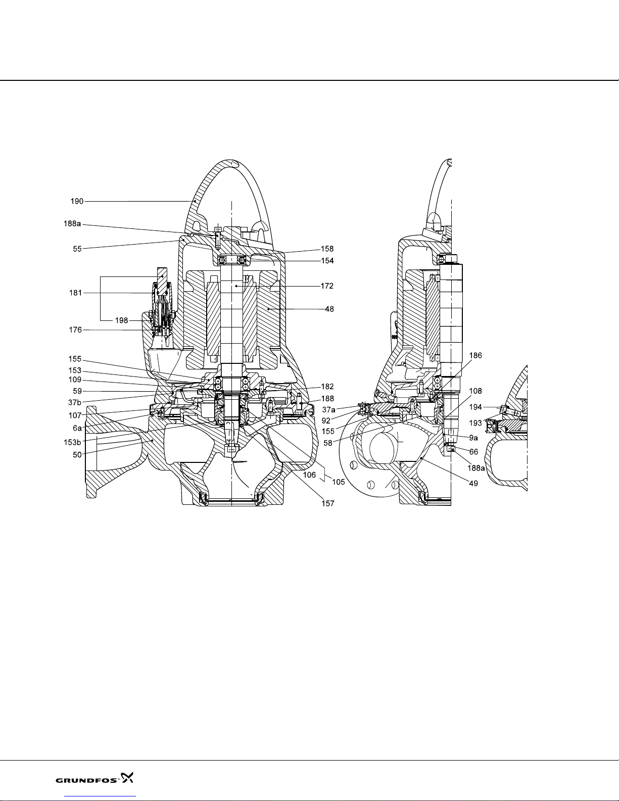
Fig. 3 Sectional drawing , SL1 pu mps w ithou t sens or
16
TM04 2787 2908
Page 17
Construction
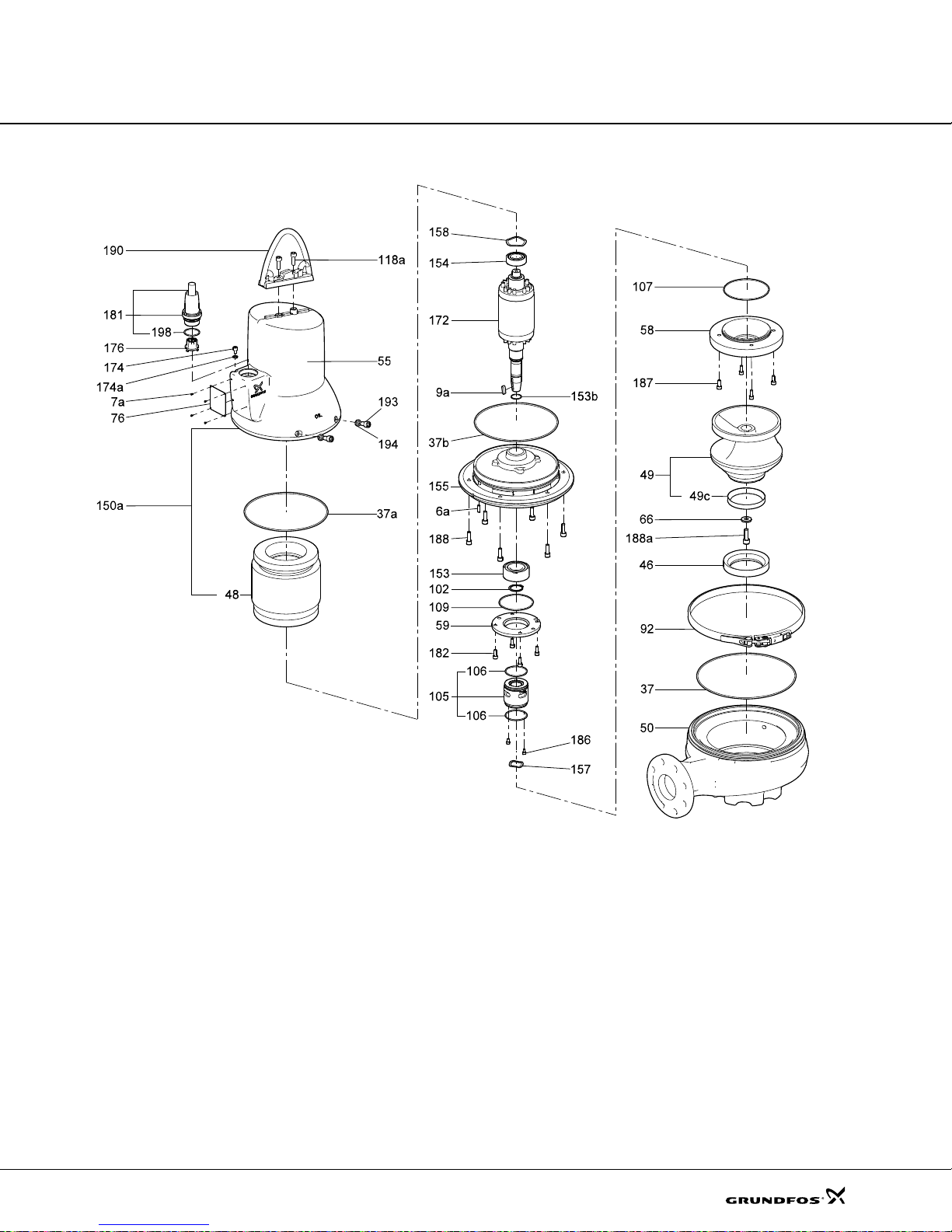
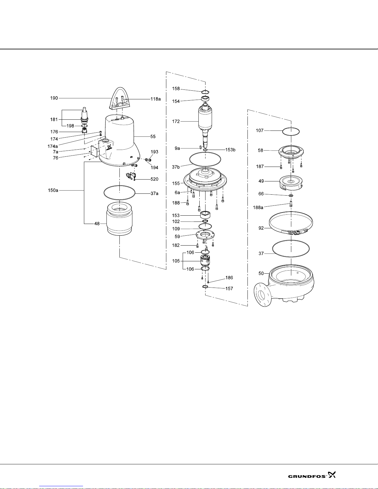
Fig. 4 Exploded view, SL1 pumps without sensor
TM04 2777 2908
17
Page 18
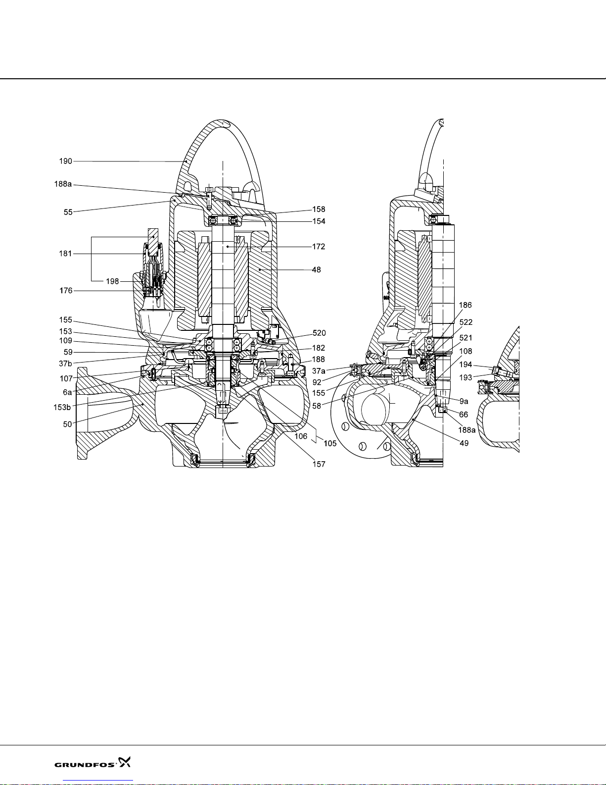
Construction
Fig. 5 Sectional drawing , SL 1 pumps E X ve rsion
TM04 7575 2110
18
Page 19
Construction
Fig. 6 Exploded view, SL1 pumps EX version
TM047077 1610
19
Page 20
Construction
Fig. 7 Sectional drawing , SL1 pu mps w ith sens or
TM04 2788 2908
20
Page 21

Construction
Fig. 8 Exploded view, SL1 pumps with sens or
TM02 2778 0904
21
Page 22
Construction
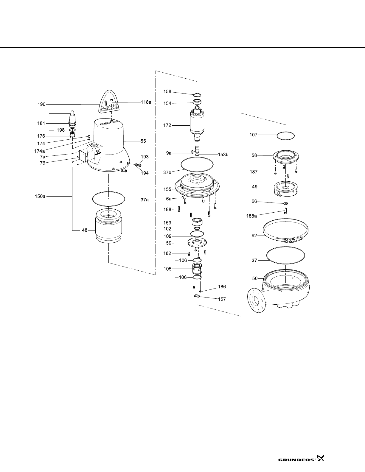
SLV
Fig. 9 Exploded view, SLV pumps without sensor
TM04 2785 2908
22
Page 23
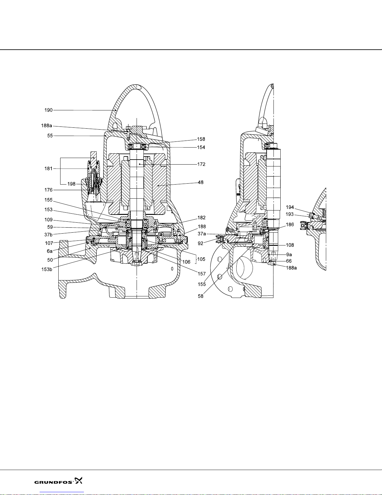
Construction
Fig. 10 Sectional drawin g, S LV pumps without sensor
TM04 2779 2908
23
Page 24
Construction
520
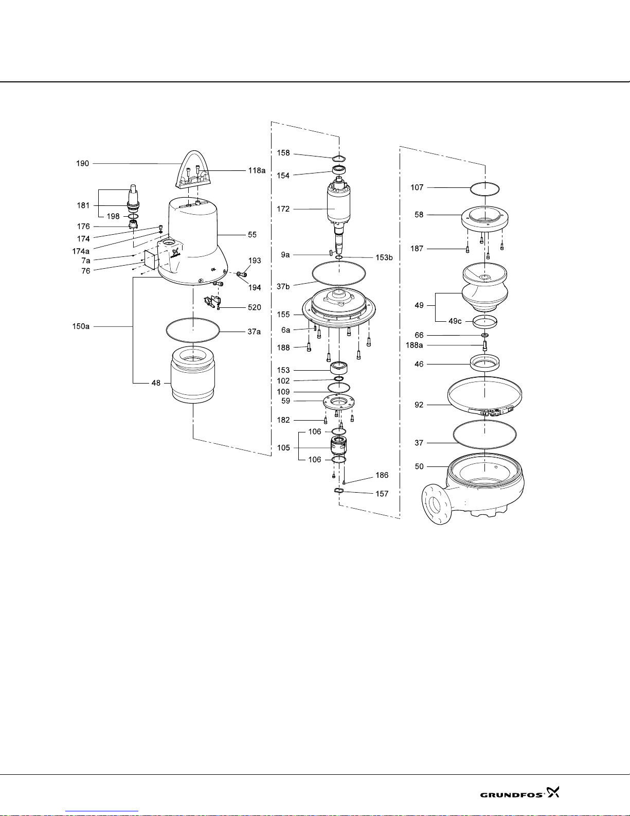
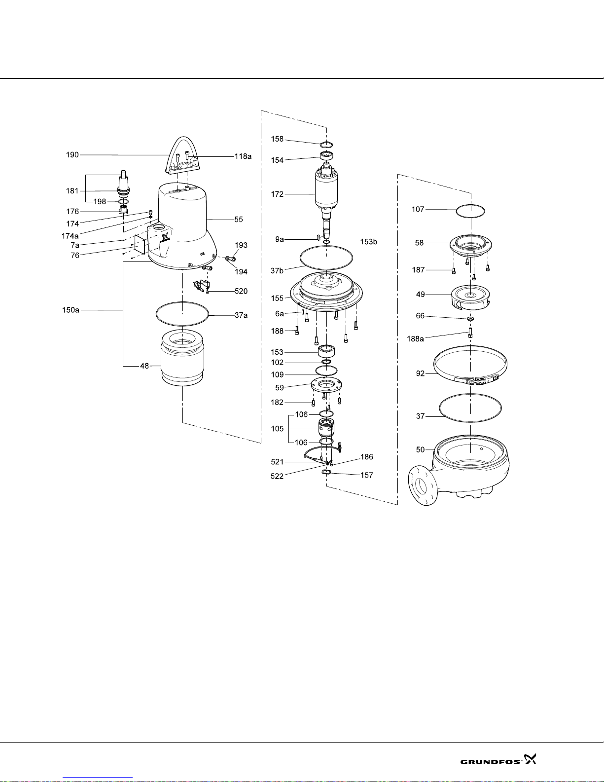
Fig. 11 Exploded view, SLV pumps EX version
TM04 7576 2110
24
Page 25
Construction
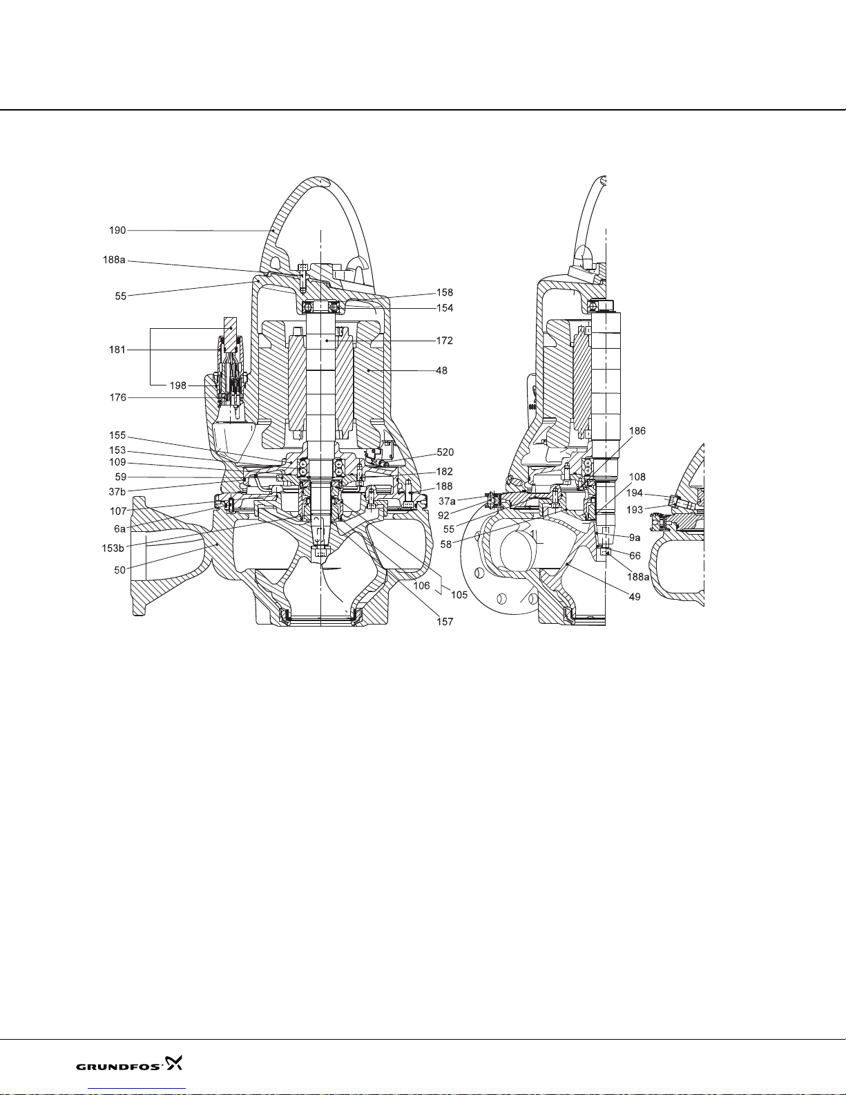
Fig. 12 Sectional dra wing, S LV pumps EX version
TM04 2779 2908
25
Page 26

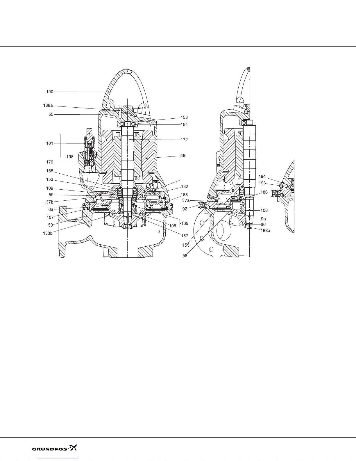
Construction
Fig. 13 Sectional drawin g, S LV pumps with sensor
TM04 2786 2908
26
Page 27
Construction
Fig. 14 Exploded view, SLV pumps with sensor
TM04 2780 2908
27
Page 28

Construction
Components and material specification
Pos. Component Material
6a Tubular pin D 8 x 22 A2 Stainless steel 1.4301 304
7a Blank rive t 2.4 x 6 A 2 Stainless steel 1.4301 304
37 O-Ring NBR rubber
37a O-Ring NBR rubber
48 Stator package
49 Impeller Cast iron GG20 EN-JL 1030
55 Stator housing Cast iron GG20 EN-JL 1030
58 Cover fo r oil chamber Cast iron GG 2 0 EN-JL 1030
59 Bearing cover Cast iron GG25 EN-JL 1040
76 Nameplate Stainless steel 1.4401 316
92 Clamp Stainless steel 1.4401 316
102 Circlip
Shaft seal cpl.
(rotating part of M G1 /2 5- G6 0 Q1 Q1 P GG
105
stationary part of MG1/25-G60 Q1Q1PGG;
rotating part of BT-AR/25 BXPFF
stationary par t of B T-AR/25 BX PF F )
106 O-ring for shaft seal NBR rubber
107 O-ring (cover for oil chamber/cover for oil chamber) NBR rubber
109 O-ring for bearing cover D-end NBR rubber
150a Stator housing co m pl e te wit h stator
153 Bearing, D-end Stainless steel
153b O-ring NBR rubber
154 Bearing, N-end Stainless steel
155 Oil chamber Cast iron GG25 EN-JL1040
157 Corrugated spring (b eari ng D-en d) Stainless steel
158 Corrugated spring (b eari ng N-en d) Stainless steel
172 Shaft with rotor Regular iron/stainless steel 1.0570 1.4401 316
174 Earth screw, external Stainless steel
174a Washer for external earth screw Stainless steel
176 Connector set (internal part)
181 Cable with outer plug part 7G AWG 14 + 3G AWG 16
182 Screw Stainless steel 1.4436 316
186 Screw Stainless steel 1.4436 316
188 Screw Stainless steel 1.4436 316
190 Lifting handle Stainless steel 1.4308
193 Plug Stainless steel 1.4436 316
194 Gasket
198 O-ring NBR rubber
520 Moisture switch (only sensor versions)
521 WIO sensor (only sensor versions)
522 Bracket for WIO sensor (only sensor versions) Stainless steel
Stainless steel, SiC/SiC
Carbon/ceram i c
DIN W. –Nr. /
EN standard
AISI / ASTM
28
Page 29
Product description
Features
Ball bearings
The bearings are greased for life .
Main bearings:
10 hp (7.5 kW) 4-pole,
12 hp (9.2 kW) 2-pole,
15 hp (11kW) 2-pole:
4 hp (3 kW) 4-pole to
10 hp (7.5 kW) 2-pole:
Support bearings: Single-r ow deep-groove ball
bearing.
Shaft seal
The shaft seal consists of two mechanical seals and
separates the motor from the pumped liquid.
The shaft seal is a cartridge seal for easy service. The
combination of the primary and secondary seals in a
cartridge results in shorter assembly l ength compare d
to traditional shaft seals. Fu rth ermore, t his desi gn
minimises the risk of incorrect fitting.
The primary seal is SiC/SiC and the secondar y is
carbon/ceramic.
Motor
The motor is a watertight, to tally encapsulated mot or.
Insulation class: H (356 °F (180 °C)).
Motor insulation fullfils NEMA MG1 par t 31 fo r
frequency converter duty.
Temperature rise class: A (1.5 to 8 hp) or class B (10 to
15 hp).
Enclosure class: IP68.
For motor protection and sensors, see section Sensors
below.
Angular contact bearing
3209B.2RS.C3.SYN.
Angular contact bearing
3208B.2RS.C3.SYN.
Power cables
Standard cable
Cable type
7 G AWG 16 0.523 (13.3) 1.25 (31.8) 1.875 (47.6)
4 G AWG 14 + 3 G 16 AWG 0.636 (16.2) 1.25 (31.8) 1.875 (47.6)
7 G AWG 14 + 3 G 16 AWG 0.811 (20.6) 1.5 (38.1) 2.25 (57.2)
Outer cable
diameter
[inch(mm)]
EMC cable
Cable type
2
]
[mm
4 G AWG 14 + 3 G 16 AWG
screened cable
Outer cable
diameter
[inch (mm)]
0.695 (17.7) 1.5 (38.1 ) 2.25 (57.2)
The cables are 33 ft (10 m) long as st andard. Oth er
cable lengths are available on request. See sect ion
List of variants on page 15.
The number and dimension of cables depend on t he
motor size.
Cable entry
The stainless steel plug is fastene d with a unio n nut.
The nut and O-rings provide sealing a gainst liquid
penetration.
The plug is filled with a special material that is cast into
the plug around the condu ctors of the cable to prevent
water penetrating into the motor through the cable in
case of cable breakage or in case water enters the free
cable end due to careless handling in con nection wi th
installation or service.
Sensors
As standard the pump is equipped with t hree the rmal
switches, one in each phase.
Customised analog sensor options
1. PT1000 sensors in motor phases for stator
temperature measurements.
2. WIO (water-in-oil) sensor
The WIO sensor measures the water content in t he
oil and converts the value into an analog curr ent
signal. The two sensor conductors are for power
supply as well as for carrying the sign al t o the
measuring device or controller. The sensor
measures the water content from 0 to 20 %. It also
sends a signal if the water content is outside t he
normal range (warning), or if the re is air in the o il
chamber (alarm). The sensor is fitte d in a stainless
steel tube for mechanical protection.
The WIO sensor is connected to a Grundfos IO 111
module.
3. One moisture switch.
Bending radius
Fixed
[inch(mm)]
Bending radius
Fixed Free
Free
[inch(mm)]
29
Page 30
Product description
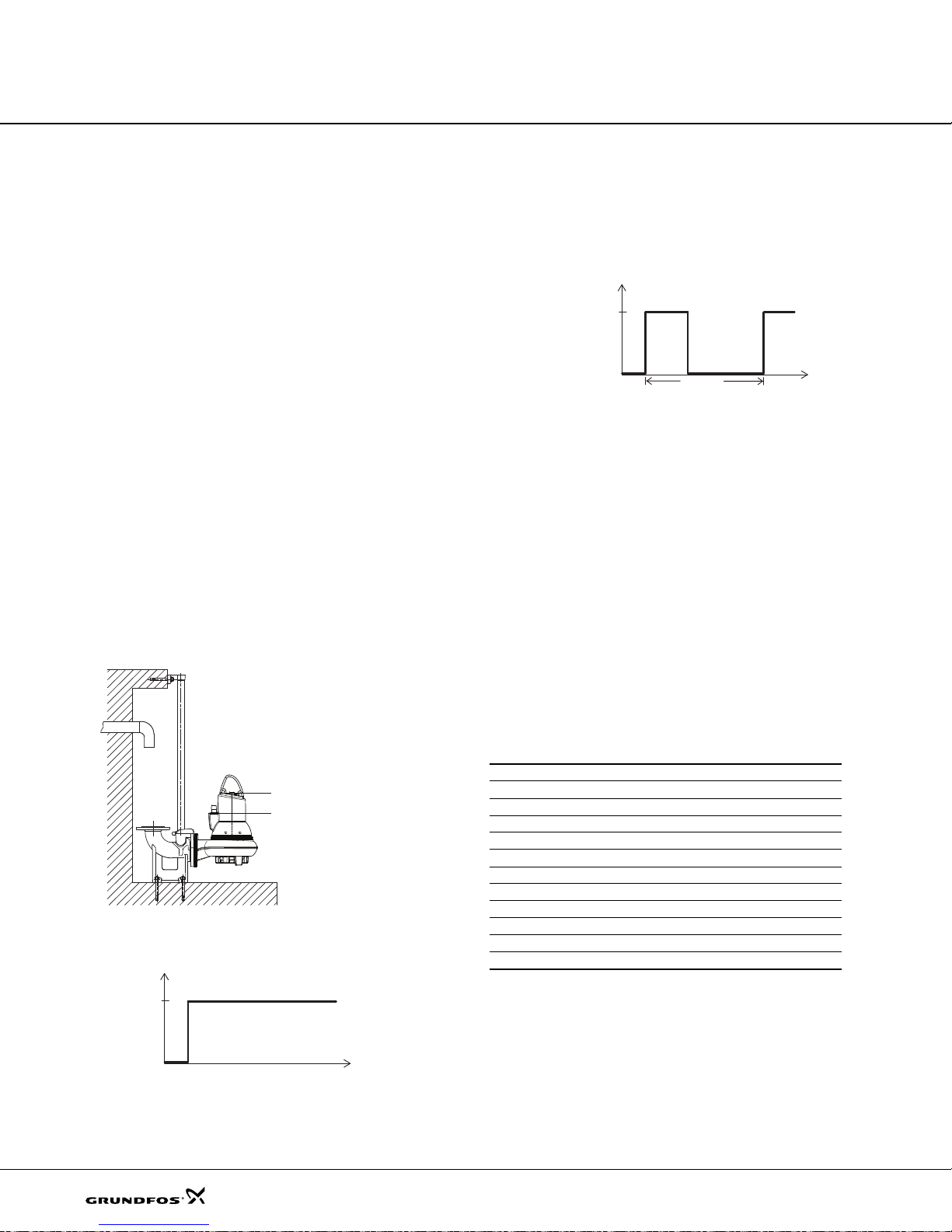
S1 operation
S3 operation
P
t
Stop
Operation
10 min
P
t
4 min 6 min
Operation
Stop
Max.
4 min.
Min. 6
min.
10 min.
IO 111 sensor module
The module collects the following signals from sensors
in the pump:
• Stator temperature
• Stator insulation resistance
• Water in oil chamber
• Moisture in motor.
Note: All pump versions with analog sensor come with
an IO 111 sensor module. It is therefore not necessary
to order an IO 111 separately.
Testing
All pumps are tested before leaving the f actory. T he
factory test report is based on HI 1.6-2000 acceptance
level B. Test reports can be ordered directly with the
pump or separately based on the pump ser ial n umber.
Other tests or third-party inspect ion certif icates a re
available on request. See section List of variants on
page 15.
Operating conditions
The SL1 and SLV pumps are only fo r sub merged
installation.
• Intermittent operation S3 with max. 20 starts per
hour when pump is submerged to the bo ttom of t he
cable plug. The pump must run for max. 4 minut es
and stop for min. 6 minutes. Se e fi g. 16.
Note: Explosion-proof pumps must always be full y
submerged.
TM04 2656 2808
Fig. 16 Intermittent operation
Pumped liquids
pH value: 4-10.
Liquid temperature: 32 °F to + 104 °F
(0 °C to + 40 °C)
When pumping liquids with a density and/or a kinematic
viscosity higher than that of wate r, use mot ors with
correspondingly higher outputs.
For short periods (max. 3 minutes), temperatures up to
140°F (60°C) are permissible (non-Ex versions only).
Sound pressure
The sound pressure level of the pump is lower than the
limiting values stated in the EC C ouncil directive 2006/
42/EC relating to machinery (Mach inery Directive) .
• Continuous operation S1 when the pump is fully
submerged to the top of the moto r.
Fig. 15 Continuous ope ration
30
Motor range
Shaft power [hp (kW)] No of poles
1.5 (1.1) 4
1.8 (1.3) 4
2.0 (1.5) 4
3.0 (2.2) 2/4
4.0 (3.0) 2/4
5.5 (4.0) 2/4
TM04 2649 2808TM02 7776 4003
7.5 (5.5) 4
8.0 (6.0) 4
10.0 (7.5) 2/4
12.5 (9.2) 2
15.0 (11) 2
Page 31

Product description
Pump controllers
The pumps must be connected to a control box w ith a
motor protection relay with IEC t rip class 10 or 15.
Note: Pumps for hazardous locatio ns must be
connected to a control box with a motor protection relay
with an IEC trip class 10 .
The pumps can be controlled by Grundf os Dedicat ed
Controls that enables control of one u p to six pumps.
The Dedicated Controls system starts/stops the SL1
and SLV pumps by means of:
• float switches
• pressure sensor
• ultrasonic sensor.
The Grundfos Dedicated Controls system offe rs the
following features and benefi ts:
Basic features
• Pump start/stop
• alternating operation of two pumps
• overflow detection
• overflow measurement
• alarms and warnings
• advanced alarm schedules
• start and stop delays
• free language selection.
Advanced features
• Daily emptying
• foam draining
• anti-seizing
• safety after-run delay
• mixer or flush valve
• maximum number of running pumps
• pump flow measurement
• system flow measurement
• pump flow calculation
• system flow calculation.
Additional features
• Insulation resistance alarm
• moisture-in-motor alarm.
These features are directly related to the actual system
configuration and the modules insta lled.
Communication features
• Complete overview of the pump installation
• setpoint change, resetting of system and start/stop
of pumps
• access to complete alarm/warning log
• automatic redirection of alarms and warnings to t he
on-duty staff
• optimisation of your maintenance and service
program
• reduction in energy consumption of the system
• Modbus RTU communication via cable
• Modbus RTU communication via GSM/GPRS
• SMS messaging
• VNC connection for migration of user inte rface to
a web browser.
PC-T ool featu res
Used for
• commissioning
• monitoring pump condition
• adjusting settings
• start/stop of pumps
• acquiring data logs
• creating operation reports
• creating service reports.
Benefits
• Easy installation and configuration.
• Configuration wizard that helps the user to configure
the system during start-up.
• Electrical overview via the CU 361 operator display,
for easy maintenance.
• Help texts for settings shown on the operator
display.
• Advanced data communication.
• Advanced alarm and warning priority.
• PC-Tool support.
• VNC (Virtual Network Computing).
• GSM/GPRS, SMS (tran smit and rece iv e), SC AD A,
BMS and PLC support.
• Data logging such as alarms, runtime, flow,
overflow, volume, energy, etc.
• Service-cost-optimised installation.
• Use of easy-to-configure rotating week schedules to
plan ahead.
31
Page 32

Product description
Variable frequency drive operation
In principle, all three-phase motors can be connected to
a frequency converter.
However, frequency converter operation w ill often
expose the motor insulation system to a hea vier load
and cause the motor to be more noisy than usual due to
eddy currents caused by voltage peaks.
In addition, large motors dr iven via a freque ncy
converter will be loaded by bearing currents.
For more information, please se e the Installati on an d
operation manual US-P/N 97640137 at
www.grundfos.com
Approvals
The SL1 and SLV pumps have been approved by CSA
and FM, and the explosion-proof versions hold an F M
type examination certificate no.: 3035318
Approval standards
These pumps are approved by CSA and FM according
to UL778, C22.2 no 108 and FM 3600, FM3615 and
FM3615.80.
Explanation to FM approval
The SL1 and SLV pumps have the following explosion
protection classification: Class I, Division 1, Gr oups C
and D, T4, T3, IP68
Standards Code Description
Explosive atmo sp he re is
caused by gas or
=
vapours.
Area classificatio n
=
Classification of gases
=
maximum surface
temperature is 275 °F
=
(135 °C) and 392 °F
(200 °C)
Enclosure class
=
according to IEC 60 529.
FM3600
FM3615
FM3615.80
Class I
Division 1
Groups C
and D
T4/T3
IP68
32
Page 33

Product description
Standard version
Thermal switches
CSA approved
Ex. version
Thermal switch and moistur e switch
CSA and FM appro ve d
Sensor version
Thermal switch and PT1000 resistor
Moisture switch and water-in -oil se nsor
CSA approved, with/without FM approval
Wiring diagrams
Fig. 17 Wiring diagram, 7-core cable, DO L
tm04 6689 0710
33
Page 34

Product description
Standard version
Thermal switches
CSA approved
Ex. version
Thermal switch and mo istu re sw itch
CSA and FM approved
Sensor version
Thermal switch an d PT10 00 res isto r
Moisture switch and wate r-in-oil s enso r
CSA approved, with/without FM approval
Fig. 18 Wiring diagram, 10-core c able, star/de lta (Y/D )
tm04 6690 0710
34
Page 35

Product description
Standard version
Thermal switches
CSA approved
Ex. version
Thermal switch and moistur e switch
CSA and FM appro ved
Sensor version
Thermal switch and PT10 00 r esisto r
Moisture switch and wate r-in- oil sen sor
CSA approved, with/w ithou t FM a pproval
Fig. 19 Wiring diagram, 10-core c able , star-co nne cte d (Y)
tm04 6691 0710
35
Page 36

Product description
Standard version
Thermal switches
CSA approved
Ex. version
Thermal switch and moisture switch
CSA and FM approved
Sensor version
Thermal switch an d PT 1000 r esist or
Moisture switch and water - in- oil sensor
CSA approved, wit h/with out FM appr oval
Fig. 20 Wiring diagram, 10-core c able, delta-con nect ed (D)
tm04 6692 0710
36
Page 37

Curve charts and
technical data
The following pages are divided into sections:
Pages 38 and 39 give a brief expla nation of how to read the curve chart s, t he curve condi tions, etc.
Performance curves and technical data:
Page Pump curves Page Pump curves Page Pump curves Page Pump curves
Performance curves
40
SL1.20.A25. 30
Performance curves
42
SL1.20.A25. 40
Performance curves
44
SL1.20.A25. 55
Performance curves
46
SL1.20.A30. 30
Performance curves
48
SL1.20.A30. 40
Performance curves
50
SL1.20.A30. 55
Performance curves
52
SL1.30.A30. 20
Performance curves
54
SL1.30.A30. 30
Performance curves
56
SL1.30.A30. 40
Performance curves
58
SL1.30.A30. 55
Performance curves
60
SL1.30.A30. 75
Performance curves
62
SL1.30.A30. 10 0
Performance curves
64
SL1.30.A40. 20
Performance curves
66
SL1.30.A40. 30
Performance curves
68
SL1.30.A40. 40
Performance curves
70
SL1.30.A40. 55
Performance curves
72
SL1.30.A40. 75
Performance curves
74
SL1.30.A40. 10 0
Performance curves
76
SL1.40.A40. 55
Performance curves
78
SL1.40.A40. 75
Performance curves
80
SL1.40.A40. 10 0
Performance curves
82
SL1.40.A60. 55
Performance curves
84
SL
Performance curves
86
SL1.40.A60. 10 0
Performance curves
88
SLV. 25.A25.30
Performance curves
90
SLV. 25.A25.40
Performance curves
92
SLV. 25.A25.55
Performance curves
94
SLV. 25.A30.30
1.40.A6
0.75
40 96
40 98
40 100
40 102
40 104
40 106
40 108
40 110
40 112
40 114
40 116
40 118
40 120
40 122
Performance curves
SLV. 25.A30.40
Performance curves
SLV. 25.A30.55
Performance curves
SLV. 30.A30.15
Performance curves
SLV. 30.A30.18
Performance curves
SLV. 30.A30.20
Performance curves
SLV. 30.A30.30
Performance curves
SLV.30.A30.55, 2- pol e
Performance curves
SLV.30.A30.55, 4- pol e
Performance curves
SLV. 30.A30.80
Performance curves
SLV.30.A30.100
Performance curves
SLV.30.A30.125
Performance curves
SLV.30.A30.150
Performance curves
SLV. 30.A40.15
Performance curves
SLV. 30.A40.18
124
126
128
130
132
134
136
138
140
142
144
146
Performanc e curve s
SLV.30.A40.20
Performanc e curve s
SLV.30.A40.30
Performanc e curve s
SLV.30.A40.55, 2- p ole
Performanc e curve s
SLV.30.A40.55, 4- p ole
Performanc e curve s
SLV.30.A40.80
Performanc e curve s
SLV.30.A40.100
Performanc e curve s
SLV.30.A40.125
Performanc e curve s
SLV.30.A40.150
Performanc e curve s
SLV.40.A40.40
Performanc e curve s
SLV.40.A40.55
Performanc e curve s
SLV.40.A40.75
Performanc e curve s
SLV.40.A40.100
37
Page 38

Curve charts and
0 50 100 150 200 250 300 350 Q [US GPM]
0
5
10
15
20
25
30
35
40
45
[ft]
H
0 2 4 6 8 10 v [ft/s]
10
15
20
25
30
35
40
45
50
[%]
Eff
0 1 2 3 4 v [ft/s]
0 2 4 6 8 10 12 14 16 18 20 22 24 Q [l/s]
0
2
4
6
8
10
12
14
[m]
H
SLV.30.A40.30.4.6
60 Hz
ISO 9906 Annex A
Eff 2
Eff 1
QH
ANSI 4 / DN 100
ANSI 6 / DN 150
0 50 100 150 200 250 300 350 Q [US GPM]
0.5
1.0
1.5
2.0
2.5
3.0
3.5
[hp]
P
0 2 4 6 8 10 12 14 16 18 20 22 24 Q [l/s]
0
10
20
[ft]
NPSH
0.5
1.0
1.5
2.0
2.5
[kW]
P
0
2
4
6
[m]
NPSH
P2
P1
Pump typeQH curve
Eta1 and Eta 2 curves of
the individual pump
Total pump he ad
H = H
total
Power curves
indicating input power
(P
1
) and output power
(P
2
) of the pump
NPSH cuves. When
sizing the pumps, ad d a
safety margin of at least
0.5 m.
technical data
How to read the curve charts
38
TM04 7268 1810
Page 39

Curve charts and
H
total
H
geoHstatHdyn
++=
technical data
Curve conditions
The guidelines below apply to the curves shown in the
performance charts on page 40 to pag e 147.
• Tole rances accordi ng t o: HI 1.6- 2000 a cceptance
level B
• The curves show pump performance w ith different
impeller diameters at the nominal speed .
• The bold part of the curves show the
recommended operating range.
• The curves apply to the pumping of airless water at
a temperature of +68 °F (+ 20 ° C) and a kine matic
viscosity of 1 cSt (1.076 (ft2/s)x10-5).
• ETA: The lines show values of the hydraulic
efficiency of the pump for the different impeller
diameters.
• NPSH: The curves show average values measured
under the same conditions as the per forman ce
curves.
When dimensioning the pump, add a safety margin
of at least 1.6 ft (0.5 m).
• In case of other densities than 13 3.5 o unces/gallon
(1000 kg/m
to the density.
• When pumping liquids with a density h igher than
133.5 ounces/gallon (1000 kg/m
correspondingly higher outputs must be used.
Calculation of total head
The total pump head consists of th e hei ght d ifference
between the measuring points + the differential head +
the dynamic head.
3
), the discharge pressure is proportional
3
), motors with
Performance tests
The requested duty point for ever y pump is te sted
according to HI 1.6-2000 acceptance level B, and
without certification.
In case of pumps ordered on the basi s of impeller
diameter only (no requested duty po int) , the pump wil l
be tested at a duty point which is 2/3 of the maximum
flow of the published performance curve which is
related to the ordered impeller diameter (according to
Hydraulic Institute 1.6-2000 accept ance l evel B).
If the customer requires either more points on the curve
to be checked or certain minimum perfor mances o r
certificates, individual measurements must b e made,
and a certificate can be ordered.
Certificates
Certificates have to be confirmed for every ord er a nd
are available on request. See secti on List of variants
on page 15
Witness test
It is possible for the customer to witness t he te sting
procedure according to Hydraulic I nstitu te 1.6-2 000.
The witness test is not a certificate and will not result in
a written statement from Grundfos. The witness itself is
the only guarantee that everything is car ried out as
prescribed in the testing procedure.
If the customer wants to witness the test of pump
performance, this request must be st ated on t he order.
H
: Height diffe rence between measuring points.
geo
: Differential head between suction and the
H
stat
discharge side of the pump.
H
: Calculated values based on the velocity of the
dyn
pumped liquid on the suction and the discharge
side of the pump.
39
Page 40

0 50 100 150 200 250 Q [US GPM]
0
10
20
30
40
50
60
70
80
[ft]
H
0 2 4 6 8 10 12 14 16 18 v [ft/s]
0
10
20
30
40
50
60
70
[%]
Eff
0 2 4 6 8 10 12 v [ft/s]
0 2 4 6 8 10 12 14 16 18 Q [l/s]
0
5
10
15
20
25
[m]
H
SL1.20.A25.30.2
60 Hz
ISO 9906 Annex A
Eff 2
Eff 1
QH
Ansi 2½ / DN 65
ANSI 3 / DN 80
0 50 100 150 200 250 Q [US GPM]
0
1
2
3
4
[hp]
P
0 2 4 6 8 10 12 14 16 18 Q [l/s]
0
10
20
30
[ft]
NPSH
0
1
2
3
[kW]
P
0
2
4
6
8
[m]
NPSH
P2
P1
Performance curves
Technical data
SL1.20.A25
Performance curves SL1.20.A25.30
SL1, SLV pumps
40
TM04 7833 2310
Page 41

Performance curves
Technical data
Dimensional sketches SL1.20.A25.30
SL1, SLV pumps
A C D E F H DN1 Dc1 DØ1 D1n DN2 Dc2 DØ2 D2n Weight [lb/kg]
[inch] 25.236 14.409 6.732 8.504 1 2.6 38 3.661 2.5 5.5 4xM16 2.5 5.5 4x0. 75 190. 9
[mm] 641 366 171 216 321 93 65 139.7 4xM16 65 139.7 4x19.1 86.6
Z2 Z3 Z4 Z6 Z7 Z8 Z9 Z10 Z11 Z12a Z14 Z15 Z16 ZDN1 ZM
[inch] 8.270 3.740 5.510 27.56 20.2 14.290 3.19 1.5" 29.13 3.898 0.04 6.89 10.472 2.5 4XM16
[mm] 210 9 5 140 700 513 363 81 1.5" 740 99 1 17 5 266 65 4XM16
V1 V2 V3 V4 V5 V6 V7 VØ
[inch] 30.354 13.346 5.118 12.795 10.63 19.331 2.559 0.709
[mm] 771 339 130 325 270 491 65 18
Electrical data
0.17
0.17
0.17
Breakdown
2
2
)]
torque
M
max
[lbf*ft
(Nm)]
14.01 (19)
18.44 (25)
16.96 (23)
Pump type
SL1.20.A25.30.2.61J
SL1.20.A25.30.2.61H 3x460V D
SL1.20.A25.30.2.61L 3x575V D
Voltage
[V]
3x208-230V D
/ 460V Y
P1
[kW]
3.9
(2.9)
3.9
(2.9)
3.9
(2.9)
I
NIstart
P2
No of
[kW]
poles
3.0
2 3480 SD 8.8 68.7 67.7 7 2.8 74.3
(2.2)
3.0
2 3520 SD 4.3 44.0 66.7 7 3.3 76.1
(2.2)
3.0
2 3510 SD 3.2 32.1 67.7 7 3.0 75.8
(2.2)
RPM
Starting
method
[A] [A] 1/2 3/4 1/1 1/2 3/4 1/1
η
motor
[%]
Cos ϕ
0.8
0.89 0.91 1.15
5
0.7
0.85 0.88 1.15
7
0.8
0.87 0.89 1.15
1
SF
Moment
of inertia
[lb*ft
(kgm
(0.00704)
(0.00704)
(0.00704)
Pump data
Max. solids
Impeller type
Channel 2 / 50 10 20 65 / 2 0 IP68 H A 104 / 40 4-10
size
[Inch / mm] PN [Feet / m] [°F / °C]
Pump housing
pressure
Max . number of
starts per hour
Max. installation
depth
Enclosure
class
Insulation
class
Temperature
rise class
Max. liquid
temperatur e
TM04 2794 3008/TM04 2795 3008/TM04 3473 4608
pH
41
Page 42

0 50 100 150 200 250 Q [US GPM]
0
10
20
30
40
50
60
70
80
90
[ft]
H
0 2 4 6 8 10 12 14 16 18 v [ft/s]
0
10
20
30
40
50
60
70
[%]
Eff
0 2 4 6 8 10 12 v [ft/s]
0 2 4 6 8 10 12 14 16 18 Q [l/s]
0
5
10
15
20
25
[m]
H
SL1.20.A25.40.2
60 Hz
ISO 9906 Annex A
Eff 2
Eff 1
QH
Ansi 2½ / DN 65
ANSI 3 / DN 80
0 50 100 150 200 250 Q [US GPM]
0
1
2
3
4
5
[hp]
P
0 2 4 6 8 10 12 14 16 18 Q [l/s]
0
10
20
30
[ft]
NPSH
0
1
2
3
[kW]
P
0
2
4
6
8
[m]
NPSH
P2
P1
Performance curves
Technical data
Performance curves SL1.20.A25.40
SL1, SLV pumps
TM04 7834 2310
42
Page 43

Performance curves
Technical data
Dimensional sketches SL1.20.A25.40
A C D E F H DN1 Dc1 DØ1 D1n DN2 Dc2 DØ2 D2n Weight [lb /kg]
[inch] 25.236 14.409 6.732 8.504 1 2.6 3 8 3.661 2.5 5.5 4xM16 2. 5 5.5 4x0.75 197.8
[mm] 641 366 171 216 321 93 65 139.7 4xM16 65 139.7 4x19.1 89.7
Z2 Z3 Z4 Z6 Z7 Z8 Z9 Z10 Z11 Z12a Z14 Z15 Z16 ZDN1 ZM
[inch] 8.270 3.74 5.51 27.56 20.2 14.29 3.19 1.5" 29.13 3.898 0.04 6.89 10.472 2.5 4XM16
[mm] 210 95 140 700 513 363 81 1.5" 740 99 1 175 2 66 65 4XM16
V1 V2 V3 V4 V5 V6 V7 VØ
[inch] 30.354 13.346 5.118 12.795 10.63 19.331 2.559 0.709
[mm] 771 339 130 325 270 491 65 18
Electrical data
Pump type
SL1.20.A25.40.2.61J
SL1.20.A25.40.2.61L 3x575V D
SL1.20.A25.40.2.61H 3x460V D
Voltage
[V]
3x208-230V D
/ 460V Y
P1
[kW]
5.1
(3.8)
5.1
(3.8)
5.1
(3.8)
I
P2
No of
[kW]
poles
4.0
2 3510 SD 11.6 99.5 72.9 77.2 78.4 0.79 0.86 0. 89 1.15
(3.0)
4.0
2 3510 SD 4.5 47.9 72.9 77.8 79.6 0.74 0.82 0.87 1.15
(3.0)
4.0
2 3510 SD 5.9 63.5 72.5 77.4 79.7 0.66 0.77 0.83 1.15
(3.0)
RPM
Starting
method
NIstart
[A] [A] 1/2 3/4 1/1 1/2 3/ 4 1/1
η
motor
[%]
Cos ϕ
SF
Moment
of inertia
2
[lb*ft
2
(kgm
)]
0.23
(0.00956)
0.23
(0.00956)
0.23
(0.00956)
Breakdown
torque
M
[lbf*ft (Nm)]
22.86 (31)
28.03 (38)
29.5 (40)
max
Pump data
Max. solids
Impeller type
Channel 2 / 50 10 20 65 / 2 0 IP68 H A 104 / 40 4-10
size
[Inch / mm] PN [Feet / m] [°F / °C]
Pump housing
pressure
Max . number of
starts per hour
Max. installation
depth
Enclosure
class
Insulation
class
Temperature
rise class
Max. liquid
temperatur e
TM04 2794 3008/TM04 2795 3008/TM04 3473 4608
pH
43
Page 44

0 50 100 150 200 250 Q [US GPM]
0
10
20
30
40
50
60
70
80
90
100
[ft]
H
0 2 4 6 8 10 12 14 16 18 v [ft/s]
0
10
20
30
40
50
60
70
[%]
Eff
0 2 4 6 8 10 12 v [ft/s]
0 2 4 6 8 10 12 14 16 18 Q [l/s]
0
5
10
15
20
25
30
[m]
H
SL1.20.A25.55.2
60 Hz
ISO 9906 Annex A
Eff 2
Eff 1
QH
Ansi 2½ / DN 65
ANSI 3 / DN 80
0 50 100 150 200 250 Q [US GPM]
2
3
4
5
6
7
[hp]
P
0 2 4 6 8 10 12 14 16 18 Q [l/s]
0
10
20
30
[ft]
NPSH
2
3
4
5
[kW]
P
0
2
4
6
8
[m]
NPSH
P2
P1
Performance curves
Technical data
Performance curves SL1.20.A25.55
SL1, SLV pumps
TM04 7835 2310
44
Page 45

Performance curves
Technical data
Dimensional sketches SL1.20.A25.55
SL1, SLV pumps
A C D E F H DN1 Dc1 DØ1 D1n DN2 Dc2 DØ2 D2n Weight [lb /kg]
[inch] 26.654 16.024 7.874 8.937 1 4.9 2 1 3.661 2.5 5.5 4xM16 2. 5 5.5 4x0.75 254.9
[mm] 677 407 200 227 379 93 65 139.7 4xM16 65 139.7 4x19.1 115.6
Z2 Z3 Z4 Z6 Z7 Z8 Z9 Z10 Z11 Z12a Z14 Z15 Z16 ZDN1 ZM
[inch] 8.270 3.740 5.510 29.17 21.81 14.76 3.19 1.5" 30.47 3.819 0.04 6.89 10.472 2.5 4XM16
[mm] 210 95 140 741 5 54 375 81 1.5" 774 97 1 175 2 66 65 4 X M1 6
V1 V2 V3 V4 V5 V6 V7 VØ
[inch] 31.772 13.425 5.118 12.795 10.63 20.433 2.559 0.709
[mm] 807 341 130 325 270 519.000 65 18
Electrical data
Pump type
SL1.20.A25.55.2.61J
SL1.20.A25.55.2.61L 3x575V D
SL1.20.A25.55.2.61H 3x460V D
Voltage
[V]
3x208-230V D
/ 460V Y
P1
[kW]
6.6
(4.9)
6.6
(4.9)
6.6
(4.9)
I
P2
No of
[kW]
poles
5.5
2 3530 SD 14.8 152 75.0 79.9 81.7 0.78 0.86 0.90 1.15
(4.0)
5.5
2 3535 SD 5.8 70.8 74.1 79.6 82.0 0.71 0.82 0.87 1.15
(4.0)
5.5
2 3540 SD 7.4 96.8 73.6 79.2 82.0 0.68 0.80 0.85 1.15
(4.0)
RPM
Starting
method
NIstart
[A] [A] 1/2 3/4 1/1 1/2 3/ 4 1/1
η
motor
[%]
Cos ϕ
SF
Moment
of inertia
2
[lb*ft
2
(kgm
)]
0.38
(0.0159)
0.38
(0.0159)
0.38
(0.0159)
Breakdown
torque
M
[lbf*ft (Nm)]
53.84 (73)
44.99 (61)
37.62 (51)
max
Pump data
Max. solids
Impeller type
Channel 2 / 50 10 20 65 / 2 0 IP68 H A 104 / 40 4-10
size
[Inch / mm] PN [Feet / m] [°F / °C]
Pump housing
pressure
Max . number of
starts per hour
Max. installation
depth
Enclosure
class
Insulation
class
Temperature
rise class
Max. liquid
temperatur e
TM04 2794 3008/TM04 2795 3008/TM04 3474 4608
pH
45
Page 46

0 50 100 150 200 250 Q [US GPM]
0
10
20
30
40
50
60
70
80
[ft]
H
0 2 4 6 8 10 12 v [ft/s]
0
10
20
30
40
50
60
70
[%]
Eff
0 2 4 6 8 v [ft/s]
0 2 4 6 8 10 12 14 16 18 Q [l/s]
0
5
10
15
20
25
[m]
H
SL1.20.A30.30.2
60 Hz
ISO 9906 Annex A
Eff 2
Eff 1
QH
Ansi 3 / DN 80
ANSI 4 / DN 100
0 50 100 150 200 250 Q [US GPM]
0
1
2
3
4
[hp]
P
0 2 4 6 8 10 12 14 16 18 Q [l/s]
0
10
20
30
[ft]
NPSH
0
1
2
3
[kW]
P
0
2
4
6
8
[m]
NPSH
P1
P2
Performance curves
Technical data
SL1.20.A30
Performance curves SL1.20.A30.30
SL1, SLV pumps
46
TM04 7836 2310
Page 47

Performance curves
Technical data
Dimensional sketches SL1.20.A30.30
SL1, SLV pumps
A C D E F H DN1 Dc1 DØ1 D1n DN2 Dc2 DØ2 D2n Weight [lb /kg]
[inch] 25.236 14.409 6.732 8.504 1 2.6 3 8 3.937 2.5 5.5 4xM16 3 6 8 x 0. 75 192.7
[mm] 641 366 171 216 321 100 65 139.7 4xM16 80 152.4 8x19.1 87.4
Z2 Z3 Z4 Z6 Z7 Z8 Z9 Z10 Z11 Z12a Z14 Z15 Z16 ZDN1 ZM
[inch] 8.66 3.74 6.3 28.31 20.71 14.8 3.19 1.5" 30.47 5.236 0.51 6.73 13.583 2.5 4XM16
[mm] 220 95 160 719 5 26 376 81 1.5" 774 133 13 171 345 65 4XM16
V1 V2 V3 V4 V5 V6 V7 VØ
[inch] 30.354 13.346 5.118 12.795 10.63 19.528 3. 15 0.709
[mm] 771 339 130 325 270 496 80 18
Electrical data
Pump type
SL1.20.A30.30.2.61J
SL1.20.A30.30.2.61H 3x460V D
SL1.20.A30.30.2.61L 3x575V D
Voltage
[V]
3x208-230V D
/ 460V Y
P1
[kW]
3.9
(2.9)
3.9
(2.9)
3.9
(2.9)
I
P2
No of
[kW]
poles
3.0
2 3480 SD 8.8 68.7 67.7 72.8 74.3 0.85 0.89 0.91 1.15
(2.2)
3.0
2 3520 SD 4.3 44.0 66.7 73.3 76.1 0.77 0.85 0.88 1.15
(2.2)
3.0
2 3510 SD 3.2 32.1 67.7 73.0 75.8 0.81 0.87 0.89 1.15
(2.2)
RPM
Starting
method
NIstart
[A] [A] 1/2 3/4 1/1 1/2 3/ 4 1/1
η
motor
[%]
Cos ϕ
SF
Moment
of inertia
2
[lb*ft
2
(kgm
)]
0.17
(0.00704)
0.17
(0.00704)
0.17
(0.00704)
Breakdown
torque
M
[lbf*ft (Nm)]
14.01 (19)
18.44 (25)
16.96 (23)
max
Pump data
Max. solids
Impeller type
Channel 2 / 50 10 20 65 / 2 0 IP68 H A 104 / 40 4-10
size
[Inch / mm] PN [Feet / m] [°F / °C]
Pump housing
pressure
Max . number of
starts per hour
Max. installation
depth
Enclosure
class
Insulation
class
Temperature
rise class
Max. liquid
temperatur e
TM04 2793 3008/TM04 2794 3008/TM04 2795 3008
pH
47
Page 48

0 50 100 150 200 250 Q [US GPM]
0
10
20
30
40
50
60
70
80
90
[ft]
H
0 2 4 6 8 10 12 v [ft/s]
0
10
20
30
40
50
60
70
[%]
Eff
0 2 4 6 8 v [ft/s]
0 2 4 6 8 10 12 14 16 18 Q [l/s]
0
5
10
15
20
25
[m]
H
SL1.20.A30.40.2
60 Hz
ISO 9906 Annex A
Eff 1
Eff 2
QH
Ansi 3 / DN 80
ANSI 4 / DN 100
0 50 100 150 200 250 Q [US GPM]
0
1
2
3
4
5
[hp]
P
0 2 4 6 8 10 12 14 16 18 Q [l/s]
0
10
20
30
[ft]
NPSH
0
1
2
3
[kW]
P
0
2
4
6
8
[m]
NPSH
P2
P1
Performance curves
Technical data
Performance curves SL1.20.A30.40
SL1, SLV pumps
TM04 7837 2310
48
Page 49

Performance curves
Technical data
Dimensional sketches SL1.20.A30.40
SL1, SLV pumps
A C D E F H DN1 Dc1 DØ1 D1n DN2 Dc2 DØ2 D2n Weight [lb /kg]
[inch] 25.236 14.409 6.732 8.504 1 2.6 3 8 3.937 2.5 5.5 4xM16 3 6 8 x 0. 75 199.5
[mm] 641 366 171 216 321 100 65 139.7 4xM16 80 152.4 8x19.1 90.5
Z2 Z3 Z4 Z6 Z7 Z8 Z9 Z10 Z11 Z12a Z14 Z15 Z16 ZDN1 ZM
[inch] 8.66 3.74 6.3 28.31 20.71 14.8 3.19 1.5" 30.47 5.236 0.51 6.73 13.583 2.5 4XM16
[mm] 220 95 160 719 5 26 376 81 1.5" 774 133 13 171 345 65 4XM16
V1 V2 V3 V4 V5 V6 V7 VØ
[inch] 30.354 13.346 5.118 12.795 10.630 19.528 3.15 0.709
[mm] 771 339 130 325 270 496 80 18
Electrical data
Pump type
SL1.20.A30.40.2.61J
SL1.20.A30.40.2.61L 3x575V D
SL1.20.A30.40.2.61H 3x460V D
Voltage
[V]
3x208-230V D
/ 460V Y
P1
[kW]
5.1
(3.8)
5.1
(3.8)
5.1
(3.8)
I
P2
No of
[kW]
poles
4.0
2 3510 SD 11.6 99.5 72.9 77.2 78.4 0.79 0.86 0 .8 9 1.15
(3.0)
4.0
2 3510 SD 4.5 47.9 72.9 77.8 79.6 0.74 0.82 0.87 1.15
(3.0)
4.0
2 3510 SD 5.9 63.5 72.5 77.4 79.7 0.66 0.77 0.83 1.15
(3.0)
RPM
Starting
method
NIstart
[A] [A] 1/2 3/4 1/1 1/2 3/ 4 1/1
η
motor
[%]
Cos ϕ
SF
Moment
of inertia
2
[lb*ft
2
(kgm
)]
0.23
(0.00956)
0.23
(0.00956)
0.23
(0.00956)
Breakdown
torque
M
[lbf*ft (Nm)]
22.86 (31)
28.03 (38)
29.5 (40)
max
Pump data
Max. solids
Impeller type
Channel 2 / 50 10 20 65 / 2 0 IP68 H A 104 / 40 4-10
size
[Inch / mm] PN [Feet / m] [°F / °C]
Pump housing
pressure
Max . number of
starts per hour
Max. installation
depth
Enclosure
class
Insulation
class
Temperature
rise class
Max. liquid
temperatur e
TM04 2793 3008/TM04 2794 3008/TM04 2795 3008
pH
49
Page 50

0 50 100 150 200 250 Q [US GPM]
0
10
20
30
40
50
60
70
80
90
100
[ft]
H
0 2 4 6 8 10 12 v [ft/s]
0
10
20
30
40
50
60
70
[%]
Eff
0 2 4 6 8 v [ft/s]
0 2 4 6 8 10 12 14 16 18 Q [l/s]
0
5
10
15
20
25
30
[m]
H
SL1.20.A30.55.2
60 Hz
ISO 9906 Annex A
Eff 2
Eff 1
QH
Ansi 3 / DN 80
ANSI 4 / DN 100
0 50 100 150 200 250 Q [US GPM]
2
3
4
5
6
7
[hp]
P
0 2 4 6 8 10 12 14 16 18 Q [l/s]
0
10
20
30
[ft]
NPSH
2
3
4
5
[kW]
P
0
2
4
6
8
[m]
NPSH
P2
P1
Performance curves
Technical data
Performance curves SL1.20.A30.55
SL1, SLV pumps
TM04 7838 2310
50
Page 51

Performance curves
Technical data
Dimensional sketches SL1.20.A30.55
SL1, SLV pumps
A C D E F H DN1 Dc1 DØ1 D1n DN2 Dc2 DØ2 D2n Weight [lb /kg]
[inch] 26.654 16.024 7.874 8.937 1 4.9 2 1 3.937 2.5 5.5 4xM16 3 6 8 x 0. 75 256.6
[mm] 677 407 200 227 379 100 65 139.7 4xM16 80 152.4 8x19.1 116.4
Z2 Z3 Z4 Z6 Z7 Z8 Z9 Z10 Z11 Z12a Z14 Z15 Z16 ZDN1 ZM
[inch] 8.66 3.74 6.3 29.92 22.32 15.24 3.19 1.5 31.81 5.197 0.51 6.73 13.583 2.5 4XM16
[mm] 220 95 160 760 567 387 81 1.5 80 8 132 13 171 345 65 4XM16
V1 V2 V3 V4 V5 V6 V7 VØ
[inch] 31.772 13.425 5.118 12.795 10.63 20.669 3. 15 0.709
[mm] 807 341 130 325 270 525 80 18
Electrical data
Pump type
SL1.20.A30.55.2.61J
SL1.20.A30.55.2.61L 3x575V D
SL1.20.A30.55.2.61H 3x460V D
Voltage
[V]
3x208-230V D
/ 460V Y
P1
[kW]
6.6
(4.9)
6.6
(4.9)
6.6
(4.9)
I
P2
No of
[kW]
poles
5.5
2 3530 SD 14.8 152 75.0 79.9 81.7 0.78 0.86 0.90 1.15
(4.0)
5.5
2 3535 SD 5.8 70.8 74.1 79.6 82.0 0.71 0.82 0.87 1.15
(4.0)
5.5
2 3540 SD 7.4 96.8 73.6 79.2 82.0 0.68 0.80 0.85 1.15
(4.0)
RPM
Starting
method
NIstart
[A] [A] 1/2 3/4 1/1 1/2 3/ 4 1/1
η
motor
[%]
Cos ϕ
SF
Moment
of inertia
2
[lb*ft
2
(kgm
)]
0.38
(0.0159)
0.38
(0.0159)
0.38
(0.0159)
Breakdown
torque
M
[lbf*ft (Nm)]
53.84 (73)
44.99 (61)
37.62 (51)
max
Pump data
Max. solids
Impeller type
Channel 2 / 50 10 20 65 / 2 0 IP68 H A 104 / 40 4-10
size
[Inch / mm] PN [Feet / m] [°F / °C]
Pump housing
pressure
Max . number of
starts per hour
Max. installation
depth
Enclosure
class
Insulation
class
Temperature
rise class
Max. liquid
temperatur e
TM04 2793 3008/TM04 2794 3008/TM04 2795 3008
pH
51
Page 52

0 50 100 150 200 250 300 350 400 Q [US GPM]
0
5
10
15
20
25
30
35
40
[ft]
H
0 2 4 6 8 10 12 14 16 18 20 v [ft/s]
0
10
20
30
40
50
60
70
[%]
Eff
0 2 4 6 8 10 12 v [ft/s]
0 2 4 6 8 10 12 14 16 18 20 22 24 26 28 30 Q [l/s]
0
2
4
6
8
10
12
[m]
H
SL1.30.A30.22.4
60 Hz
ISO 9906 Annex A
Eff 2
Eff 1
QH
Ansi 3 / DN 80
ANSI 4 / DN 100
0 50 100 150 200 250 300 350 400 Q [US GPM]
0.5
1.0
1.5
2.0
2.5
3.0
[hp]
P
0 2 4 6 8 10 12 14 16 18 20 22 24 26 28 30 Q [l/s]
0
5
10
[ft]
NPSH
0.5
1.0
1.5
2.0
[kW]
P
0
1
2
3
[m]
NPSH
P1
P2
Performance curves
Technical data
SL1.30.A30
Performance curves SL1.30.A30.20
SL1, SLV pumps
52
TM04 7839 2310
Page 53

Performance curves
Technical data
Dimensional sketches SL1.30.A30.20
SL1, SLV pumps
A C D E F H DN1 Dc1 DØ1 D1n DN2 Dc2 DØ2 D2n Weight [lb /kg]
[inch] 26.850 17.126 6.732 10.709 14.724 3.937 4 7.5 8xM16 3 6 8x0.75 212. 1
[mm] 682 435 171 272 374 100 100 190.5 8xM16 80 152.40 8x19.1 96.2
Z2 Z3 Z4 Z6 Z7 Z8 Z9 Z10 Z11 Z12a Z14 Z15 Z16 ZDN1 ZM
[inch] 8.66 3.74 6.3 31.02 23.43 17.01 3.19 1.5" 31.10 4.252 0.51 6.73 13.583 4 4XM16
[mm] 220 95 160 788 595 432 81 1.5" 790 108 13 171 345 100 4X M1 6
V1 V2 V3 V4 V5 V6 V7 VØ
[inch] 31.969 14.331 5.118 13.976 11.811 22.323 3.15 0.748
[mm] 812 364 130 355 300 567 80 19
Electrical data
Pump type
SL1.30.A30.20.4.60J
SL1.30.A30.20.4.60L 3x575V D
SL1.30.A30.20.4.61L 3x575V D
SL1.30.A30.20.4.61J
Voltage
[V]
3x208-230V D
/ 460V Y
3x208-230V D
/ 460V Y
P1
[kW]
2.5
(1.9)
2.5
(1.9)
2.5
(1.9)
2.5
(1.9)
I
P2
No of
[kW]
poles
2.0
4 1750 DOL 6.6 42.5 69.6 74.4 76.2 0.65 0.75 0.80 1.15
(1.5)
2.0
4 1750 DOL 2.6 20.0 68.7 74.4 77.0 0.59 0.69 0.76 1.15
(1.5)
2.0
4 1750 SD 2.6 20.0 68.7 74.4 77.0 0.59 0.69 0.76 1.15
(1.5)
2.0
4 1750 SD 6.6 42.5 69.6 74.4 76.2 0.65 0.75 0.80 1.15
(1.5)
RPM
Starting
method
NIstart
[A] [A] 1/2 3/4 1/1 1/2 3/ 4 1/1
η
motor
[%]
Cos ϕ
SF
Moment
of inertia
2
[lb*ft
2
(kgm
)]
0.67
(0.0284)
0.67
(0.0284)
0.67
(0.0284)
0.67
(0.0284)
Breakdown
torque
M
[lbf*ft (Nm)]
19.18 (26)
22.86 (31)
22.86 (31)
19.18 (26)
max
Pump data
Max. solids
Impeller type
Channel 3 / 80 10 20 65 / 2 0 IP68 H A 104 / 40 4-10
size
[Inch / mm] PN [Feet / m] [°F / °C]
Pump housing
pressure
Max . number of
starts per hour
Max. installation
depth
Enclosure
class
Insulation
class
Temperature
rise class
Max. liquid
temperatur e
TM04 2793 3008/TM04 2794 3008/TM04 2795 3008
pH
53
Page 54

0 50 100 150 200 250 300 350 400 450 500 Q [US GPM]
0
5
10
15
20
25
30
35
40
45
[ft]
H
0 2 4 6 8 10 12 14 16 18 20 22 v [ft/s]
0
10
20
30
40
50
60
70
[%]
Eff
0 2 4 6 8 10 12 14 v [ft/s]
0 2 4 6 8 10 12 14 16 18 20 22 24 26 28 30 32 34 36 Q [l/s]
0
2
4
6
8
10
12
14
[m]
H
SL1.30.A30.30.4
60 Hz
ISO 9906 Annex A
Eff 2
Eff 1
QH
Ansi 3 / DN 80
ANSI 4 / DN 100
0 50 100 150 200 250 300 350 400 450 500 Q [US GPM]
0.5
1.0
1.5
2.0
2.5
3.0
3.5
[hp]
P
0 2 4 6 8 10 12 14 16 18 20 22 24 26 28 30 32 34 36 Q [l/s]
0
5
10
[ft]
NPSH
0.5
1.0
1.5
2.0
2.5
[kW]
P
0
1
2
3
[m]
NPSH
P2
P1
Performance curves
Technical data
Performance curves SL1.30.A30.30
SL1, SLV pumps
TM04 7840 2310
54
Page 55

Performance curves
Technical data
Dimensional sketches SL1.30.A30.30
SL1, SLV pumps
A C D E F H DN1 Dc1 DØ1 D1n DN2 Dc2 DØ2 D2n Weight [lb /kg]
[inch] 26.850 17.126 6.732 10.709 14.724 3.937 4 7.5 8xM16 3 6 8x0.75 242. 5
[mm] 682 435 171 272 374 100 100 190.5 8xM16 80 152.4 8x19.1 110
Z2 Z3 Z4 Z6 Z7 Z8 Z9 Z10 Z11 Z12a Z14 Z15 Z16 ZDN1 ZM
[inch] 8.66 3.74 6.3 31.02 23.43 17.01 3.19 1.5" 31.10 4.252 0.51 6.73 13.583 4 4XM16
[mm] 220 95 160 788 595 432 81 1.5" 790 108 13 171 345 100 4X M1 6
V1 V2 V3 V4 V5 V6 V7 VØ
[inch] 31.969 14.331 5.118 13.976 11.811 22.323 3.15 0.748
[mm] 812 364 130 355 300 567 80 19
Electrical data
Pump type
SL1.30.A30.30.4.61H 3x460V D
SL1.30.A30.30.4.61J
SL1.30.A30.30.4.61L 3x575V D
Voltage
[V]
3x208-230V D
/ 460V Y
P1
[kW]
3.6
(2.7)
3.6
(2.7)
3.6
(2.7)
I
P2
No of
[kW]
poles
3.0
4 1770 SD 4.5 39.7 76.9 80.7 83.0 0.57 0.69 0.76 1.15
(2.2)
3.0
4 1750 SD 8.7 61.6 78.2 81.5 82.1 0.69 0.78 0.83 1.15
(2.2)
3.0
4 1760 SD 3.5 29.0 77.5 81.3 82.9 0.62 0.72 0.79 1.15
(2.2)
RPM
Starting
method
NIstart
[A] [A] 1/2 3/4 1/1 1/2 3/ 4 1/1
η
motor
[%]
Cos ϕ
SF
Moment
of inertia
2
[lb*ft
2
(kgm
)]
1.02
(0.0429)
1.02
(0.0429)
1.02
(0.0429)
Breakdown
torque
M
[lbf*ft (Nm)]
35.4 (48)
26.55 (36)
32.45 (44)
max
Pump data
Max. solids
Impeller type
Channel 3 / 80 10 20 65 / 2 0 IP68 H A 104 / 40 4-10
size
[Inch / mm] PN [Feet / m] [°F / °C]
Pump housing
pressure
Max . number of
starts per hour
Max. installation
depth
Enclosure
class
Insulation
class
Temperature
rise class
Max. liquid
temperatur e
TM04 2793 3008/TM04 2794 3008/TM04 2795 3008
pH
55
Page 56

0 100 200 300 400 500 600 Q [US GPM]
0
5
10
15
20
25
30
35
40
45
[ft]
H
0 5 10 15 20 25 v [ft/s]
0
10
20
30
40
50
60
70
[%]
Eff
0 5 10 15 v [ft/s]
0 5 10 15 20 25 30 35 40 45Q [l/s]
0
2
4
6
8
10
12
14
[m]
H
SL1.30.A30.40.4
60 Hz
ISO 9906 Annex A
Eff 2
Eff 1
QH
Ansi 3 / DN 80
ANSI 4 / DN 100
0 100 200 300 400 500 600 Q [US GPM]
1
2
3
4
5
6
[hp]
P
0 5 10 15 20 25 30 35 40 45Q [l/s]
0
5
10
[ft]
NPSH
1
2
3
4
[kW]
P
0
1
2
3
[m]
NPSH
P2
P1
Performance curves
Technical data
Performance curves SL1.30.A30.40
SL1, SLV pumps
56
TM04 7841 2310
Page 57

Performance curves
Technical data
Dimensional sketches SL1.30.A30.40
SL1, SLV pumps
A C D E F H DN1 Dc1 DØ1 D1n DN2 Dc2 DØ2 D2n Weight [lb /kg]
[inch] 27.992 19.882 7.874 12.559 15.6 3 4.646 4 7.5 8xM 16 3 6 8x0.75 306.9
[mm] 711 505 200 319 397 118 100 190.5 8xM16 80 152.4 8x19.1 139.2
Z2 Z3 Z4 Z6 Z7 Z8 Z9 Z10 Z11 Z12a Z14 Z15 Z16 ZDN1 ZM
[inch] 8.66 3.74 6.3 33.78 26.22 18.9 3.19 1.5" 31.22 3.228 0.51 6.73 13.583 4 4XM16
[mm] 220 95 160 858 666 480 81 1.5" 793 82 13 171 3 45 100 4XM16
V1 V2 V3 V4 V5 V6 V7 VØ
[inch] 33.11 15.354 5.118 13.976 11.811 24.528 3.15 0.748
[mm] 841 390 130 355 300 623 80 19
Electrical data
Pump type
SL1.30.A30.40.4.61J
SL1.30.A30.40.4.61L 3x575V D
SL1.30.A30.40.4.61H 3x460V D
Voltage
[V]
3x208-230V D
/ 460V Y
P1
[kW]
5.0
(3.7)
5.0
(3.7)
5.0
(3.7)
I
P2
No of
[kW]
poles
4.0
4 1760 SD 12.0 79.5 76.0 79.8 80.2 0.69 0.80 0.84 1.15
(3.0)
4.0
4 1750 SD 4.8 37.5 75.0 79.4 81.4 0.61 0 .7 2 0.80 1.15
(3.0)
4.0
4 1760 SD 6.2 51.5 74.6 79.7 81.5 0.56 0 .6 8 0.77 1.15
(3.0)
RPM
Starting
method
NIstart
[A] [A] 1/2 3/4 1/1 1/2 3/ 4 1/1
η
motor
[%]
Cos ϕ
SF
Moment
of inertia
2
[lb*ft
2
(kgm
)]
1.35
(0.0569)
1.35
(0.0569)
1.35
(0.0569)
Breakdown
torque
M
[lbf*ft (Nm)]
38.35 (52)
46.47 (63)
50.89 (69)
max
Pump data
Max. solids
Impeller type
Channel 3 / 80 10 20 65 / 2 0 IP68 H A 104 / 40 4-10
size
[Inch / mm] PN [Feet / m] [°F / °C]
Pump housing
pressure
Max . number of
starts per hour
Max. installation
depth
Enclosure
class
Insulation
class
Temperature
rise class
Max. liquid
temperatur e
TM04 2793 3008/TM04 2794 3008/TM04 2795 3008
pH
57
Page 58

0 100 200 300 400 500 600 700 Q [US GPM]
0
10
20
30
40
50
60
70
80
[ft]
H
0 5 10 15 20 25 30 v [ft/s]
0
10
20
30
40
50
60
70
[%]
Eff
0 5 10 15 20 v [ft/s]
0 5 10 15 20 25 30 35 40 45 50 Q [l/s]
0
5
10
15
20
25
[m]
H
SL1.30.A30.55.4
60 Hz
ISO 9906 Annex A
Eff 2
Eff 1
QH
Ansi 3 / DN 80
ANSI 4 / DN 100
0 100 200 300 400 500 600 700 Q [US GPM]
1
2
3
4
5
6
7
[hp]
P
0 5 10 15 20 25 30 35 40 45 50 Q [l/s]
0
5
10
[ft]
NPSH
1
2
3
4
5
[kW]
P
0
1
2
3
[m]
NPSH
P2
P1
Performance curves
Technical data
Performance curves SL1.30.A30.55
SL1, SLV pumps
58
TM04 7842 2310
Page 59

Performance curves
Technical data
Dimensional sketches SL1.30.A30.55
A C D E F H DN1 Dc1 DØ1 D1n DN2 Dc2 DØ2 D2n Weight [lb /kg]
[inch] 29.449 19.882 7.874 12.559 15.6 3 4.646 4 7.5 8xM 16 3 6 8x0.75 318.3
[mm] 748 505 200 319 397 118 100 190.5 8xM16 80 152.4 8x19.1 144.4
Z2 Z3 Z4 Z6 Z7 Z8 Z9 Z10 Z11 Z12a Z14 Z15 Z16 ZDN1 ZM
[inch] 8.66 3.74 6.3 33.78 26.22 18.9 3.19 1.5" 32.68 3.228 0.51 6.73 13.583 4 4XM16
[mm] 220 95 160 858 666 480 81 1.5" 830 82 13 171 3 45 100 4XM16
V1 V2 V3 V4 V5 V6 V7 VØ
[inch] 34.567 15.354 5.118 13.976 11.811 24.528 3.15 0.748
[mm] 878 390 130 355 300 623 80 19
Electrical data
Pump type
SL1.30.A30.55.4.61J
SL1.30.A30.55.4.61L 3x575V D
SL1.30.A30.55.4.61H 3x460V D
Voltage
[V]
3x208-230V D
/ 460V Y
P1
[kW]
6.4
(4.8)
6.4
(4.8)
6.4
(4.8)
I
P2
No of
[kW]
poles
5.5
4 1760 SD 16.1 79.4 79.9 83.3 83.9 0.61 0.74 0.80 1.15
(4.0)
5.5
4 1765 SD 6.5 37.5 79.2 83.3 84.7 0.54 0 .6 7 0.75 1.15
(4.0)
5.5
4 1770 SD 8.5 51.5 78.3 82.6 84.4 0.50 0 .6 4 0.72 1.15
(4.0)
RPM
Starting
method
NIstart
[A] [A] 1/2 3/4 1/1 1/2 3/ 4 1/1
η
motor
[%]
Cos ϕ
SF
Moment
of inertia
2
[lb*ft
2
(kgm
)]
1.73
(0.073)
1.73
(0.073)
1.73
(0.073)
Breakdown
torque
M
[lbf*ft (Nm)]
81.87 (111)
68.59 (93)
74.49 (101)
max
Pump data
Max. solids
Impeller type
Channel 3 / 80 10 20 65 / 2 0 IP68 H A 104 / 40 4-10
size
[Inch / mm] PN [Feet / m] [°F / °C]
Pump housing
pressure
Max . number of
starts per hour
Max. installation
depth
Enclosure
class
Insulation
class
Temperature
rise class
Max. liquid
temperatur e
TM04 2793 3008/TM04 2794 3008/TM04 2795 3008
pH
59
Page 60

0 100 200 300 400 500 600 700 Q [US GPM]
0
10
20
30
40
50
60
70
80
[ft]
H
0 5 10 15 20 25 30 35 v [ft/s]
0
10
20
30
40
50
60
70
[%]
Eff
0 5 10 15 20 v [ft/s]
0 5 10 15 20 25 30 35 40 45 50 55 Q [l/s]
0
5
10
15
20
25
[m]
H
SL1.30.A30.75.4
60 Hz
ISO 9906 Annex A
Eff 2
Eff 1
QH
Ansi 3 / DN 80
ANSI 4 / DN 100
0 100 200 300 400 500 600 700 Q [US GPM]
3
4
5
6
7
8
9
[hp]
P
0 5 10 15 20 25 30 35 40 45 50 55 Q [l/s]
0
5
10
[ft]
NPSH
3
4
5
6
[kW]
P
0
1
2
3
[m]
NPSH
P2
P1
Performance curves
Technical data
Performance curves SL1.30.A30.75
60
TM04 7843 2310
Page 61

Performance curves
Technical data
Dimensional sketches SL1.30.A30.75
A C D E F H DN1 Dc1 DØ1 D1n DN2 Dc2 DØ2 D2n Weight [lb /kg]
[inch] 29.724 19.882 7.874 12.559 15.6 3 4.646 4 7.5 8xM 16 3 6 8x0.75 332.7
[mm] 755 505 200 319 397 118 100 190.5 8xM16 80 152.40 8x19.1 150.9
Z2 Z3 Z4 Z6 Z7 Z8 Z9 Z10 Z11 Z12a Z14 Z15 Z16 ZDN1 ZM
[inch] 8.66 3.74 6.3 33.78 26.22 18.9 3.19 1.5" 32.95 3.228 0.51 6.73 13.583 4 4XM16
[mm] 220 95 160 858 666 480 81 1.5" 837 82 13 171 3 45 100 4XM16
V1 V2 V3 V4 V5 V6 V7 VØ
[inch] 34.843 15.354 5.118 13.976 11.811 24.528 3.15 0.748
[mm] 885 390 130 355 300 623 80 19
Electrical data
Pump type
SL1.30.A30.75.4.61J
SL1.30.A30.75.4.61L 3x575V D
SL1.30.A30.75.4.61H 3x460V D
Voltage
[V]
3x208-230V D
/ 460V Y
P1
[kW]
8.6
(6.4)
8.6
(6.4)
8.6
(6.4)
I
P2
No of
[kW]
poles
7.5
4 1760 SD 20.0 126 83.2 85.6 85.8 0.77 0.84 0.87 1.15
(5.5)
7.5
4 1765 SD 7.8 59.3 83.5 86.6 87.3 0.69 0 .7 9 0.84 1.15
(5.5)
7.5
4 1770 SD 10.0 81.4 82.9 86.3 87.2 0.65 0.75 0.81 1.15
(5.5)
RPM
Starting
method
NIstart
[A] [A] 1/2 3/4 1/1 1/2 3/ 4 1/1
η
motor
[%]
Cos ϕ
SF
Moment
of inertia
2
[lb*ft
2
(kgm
)]
2.39
(0.10056)
2.39
(0.10056)
2.39
(0.10056)
Breakdown
torque
M
[lbf*ft (Nm)]
90.72 (123)
75.97 (103)
83.34 (113)
max
Pump data
Max. solids
Impeller type
Channel 3 / 80 10 20 65 / 2 0 IP68 H A 104 / 40 4-10
size
[Inch / mm] PN [Feet / m] [°F / °C]
Pump housing
pressure
Max . number of
starts per hour
Max. installation
depth
Enclosure
class
Insulation
class
Temperature
rise class
Max. liquid
temperatur e
TM04 2793 3008/TM04 2794 3008/TM04 2795 3008
pH
61
Page 62

0 100 200 300 400 500 600 700 800 Q [US GPM]
0
10
20
30
40
50
60
70
80
90
[ft]
H
0 5 10 15 20 25 30 35 40 v [ft/s]
0
10
20
30
40
50
60
70
[%]
Eff
0 5 10 15 20 25 v [ft/s]
0 5 10 15 20 25 30 35 40 45 50 55 60 Q [l/s]
0
5
10
15
20
25
[m]
H
SL1.30.A30.100.4
60 Hz
ISO 9906 Annex A
Eff 2
Eff 1
QH
Ansi 3 / DN 80
ANSI 4 / DN 100
0 100 200 300 400 500 600 700 800 Q [US GPM]
2
4
6
8
10
12
[hp]
P
0 5 10 15 20 25 30 35 40 45 50 55 60 Q [l/s]
0
5
10
15
[ft]
NPSH
2
4
6
8
[kW]
P
0
1
2
3
4
[m]
NPSH
P2
P1
Performance curves
Technical data
Performance curves SL1.30.A30.100
TM04 7844 2310
62
Page 63

Performance curves
Technical data
Dimensional sketches SL1.30.A30.100
A C D E F H DN1 Dc1 DØ1 D1n DN2 Dc2 DØ2 D2n Weight [lb /kg]
[inch] 32.205 20.866 8.543 12.913 16.654 4.646 4 7.5 8xM16 3 6 8x0.75 435. 9
[mm] 818 530 217 328 423 118 100 190.5 8xM16 80 152.40 8x19.1 197.7
Z2 Z3 Z4 Z6 Z7 Z8 Z9 Z10 Z11 Z12a Z14 Z15 Z16 ZDN1 ZM
[inch] 8.66 3.74 6.3 34.76 27.17 19.25 3.19 1.5" 35.43 3.228 0.51 6.73 13.583 4 4XM16
[mm] 220 95 160 883 690 489 81 1.5" 900 82 13 171 3 45 100 4XM16
V1 V2 V3 V4 V5 V6 V7 VØ
[inch] 37.323 15.354 5.118 13.976 11.811 25.512 3.15 0.748
[mm] 948 390 130 355 300 648 80 19
Electrical data
Pump type
SL1.30.A30.100.4.61J
SL1.30.A30.100.4.61 L 3x5 7 5V D
SL1.30.A30.100.4.61 H 3 x 460V D
Voltage
[V]
3x208-230V D
/ 460V Y
P1
[kW]
11.5
(8.6)
11.5
(8.6)
11.5
(8.6)
No
P2
of
[kW]
pol-
es
10.0
4 1760 SD 26.6 174 85.6 86.9 86.4 0.80 0.86 0.89 1.15
(7.5)
10.0
4 1760 SD 10.2 81.2 85.3 87.4 87.9 0.74 0.83 0.86 1.15
(7.5)
10.0
4 1765 SD 13.0 111 85.0 87.6 88.1 0.70 0.80 0.85 1.15
(7.5)
RPM
Starting
method
I
NIstart
[A] [A] 1/2 3/4 1/1 1/2 3/ 4 1/1
η
motor
[%]
Cos ϕ
SF
Moment
of inertia
2
[lb*ft
2
(kgm
)]
3.18
(0.134)
3.18
(0.134)
3.18
(0.134)
Breakdown
torque
M
[lbf*ft (Nm)]
75.23 (102)
104.73
(142)
114.32
(155)
max
Pump data
Max. solids
Impeller type
Channel 3 / 80 10 20 65 / 2 0 IP68 H A 104 / 40 4-10
size
[Inch / mm] PN [Feet / m] [°F / °C]
Pump housing
pressure
Max . number of
starts per hour
Max. installation
depth
Enclosure
class
Insulation
class
Temperature
rise class
Max. liquid
temperatur e
TM04 2793 3008/TM04 2794 3008/TM04 2795 3008
pH
63
Page 64

0 100 200 300 400 Q [US GPM]
0
5
10
15
20
25
30
35
40
[ft]
H
0 2 4 6 8 10 12 14 v [ft/s]
0
10
20
30
40
50
60
70
[%]
Eff
0 1 2 3 4 5 6 v [ft/s]
0 5 10 15 20 25 30 Q [l/s]
0
2
4
6
8
10
12
[m]
H
SL1.30.A40.22.4
60 Hz
ISO 9906 Annex A
Eff 2
Eff 1
QH
Ansi 4 / DN 100
ANSI 6 / DN 150
0 100 200 300 400 Q [US GPM]
0.5
1.0
1.5
2.0
2.5
3.0
[hp]
P
0 5 10 15 20 25 30 Q [l/s]
0
5
10
[ft]
NPSH
0.5
1.0
1.5
2.0
[kW]
P
0
1
2
3
[m]
NPSH
P2
P1
Performance curves
Technical data
SL1.30.A40
Performance curves SL1.30.A40.20
64
TM04 7845 2310
Page 65

Performance curves
Technical data
Dimensional sketches SL1.30.A40.20
A C D E F H DN1 Dc1 DØ1 D1n DN2 Dc2 DØ2 D2n Weight [lb /kg]
[inch] 26.850 17.126 6.732 10.709 13.661 4.409 4 7.5 8 xM 16 4 7 .5 8x0.75 214.3
[mm] 682 435 171 272 347 112 100 190.5 8xM16 100 190.50 8x19.1 97.2
Z2 Z3 Z4 Z6 Z7 Z8 Z9 Z10 Z11 Z12a Z14 Z15 Z16 ZDN1 ZM
[inch] 1 0.24 4 .3 3 8.66 34.57 25.67 19.25 4.33 2.0" 32.68 5.827 0 8.66 16 .2 6 4 4XM16
[mm] 260 110 220 878 652 489 110 2.0" 830 148 0 220 413 100 4XM16
V1 V2 V3 V4 V5 V6 V7 VØ
[inch] 31.969 14.528 5.118 13.976 11.811 23.268 3.937 0.748
[mm] 812 369 130 355 300 591 100 19
Electrical data
Pump type
SL1.30.A40.20.4.60J
SL1.30.A40.20.4.60L 3x575V D
SL1.30.A40.20.4.61L 3x575V D
SL1.30.A40.20.4.61J
Voltage
[V]
3x208-230V D
/ 460V Y
3x208-230V D
/ 460V Y
P1
[kW]
2.5
(1.9)
2.5
(1.9)
2.5
(1.9)
2.5
(1.9)
I
P2
No of
[kW]
poles
2.0
4 1750 DOL 6.6 42.5 69.6 74.4 76.2 0.65 0.75 0.80 1.15
(1.5)
2.0
4 1750 DOL 2.6 20.0 68.7 74.4 77.0 0.59 0.69 0.76 1.15
(1.5)
2.0
4 1750 SD 2.6 20.0 68.7 74.4 77.0 0.59 0 .6 9 0.76 1.15
(1.5)
2.0
4 1750 SD 6.6 42.5 69.6 74.4 76.2 0.65 0 .7 5 0.80 1.15
(1.5)
RPM
Starting
method
NIstart
[A] [A] 1/2 3/4 1/1 1/2 3/ 4 1/1
η
motor
[%]
Cos ϕ
SF
Moment
of inertia
2
[lb*ft
2
(kgm
)]
0.67
(0.0284)
0.67
(0.0284)
0.67
(0.0284)
0.67
(0.0284)
Breakdown
torque
M
[lbf*ft (Nm)]
19.18 (26)
22.86 (31)
22.86 (31)
19.18 (26)
max
Pump data
Max. solids
Impeller type
Channel 3 / 80 10 20 65 / 2 0 IP68 H A 104 / 40 4-10
size
[Inch / mm] PN [Feet / m] [°F / °C]
Pump housing
pressure
Max . number of
starts per hour
Max. installation
depth
Enclosure
class
Insulation
class
Temperature
rise class
Max. liquid
temperatur e
TM04 2793 3008/TM04 2794 3008/TM04 2795 3008
pH
65
Page 66

0 100 200 300 400 500 Q [US GPM]
0
5
10
15
20
25
30
35
40
45
[ft]
H
0 2 4 6 8 10 12 14 16 v [ft/s]
0
10
20
30
40
50
60
70
[%]
Eff
0 1 2 3 4 5 6 7 v [ft/s]
0 5 10 15 20 25 30 35 Q [l/s]
0
2
4
6
8
10
12
14
[m]
H
SL1.30.A40.30.4
60 Hz
ISO 9906 Annex A
Eff 2
Eff 1
QH
Ansi 4 / DN 100
ANSI 6 / DN 150
0 100 200 300 400 500 Q [US GPM]
1.0
1.5
2.0
2.5
3.0
3.5
[hp]
P
0 5 10 15 20 25 30 35 Q [l/s]
0
5
10
[ft]
NPSH
1.0
1.5
2.0
2.5
[kW]
P
0
1
2
3
[m]
NPSH
P2
P1
Performance curves
Technical data
Performance curves SL1.30.A40.30
TM04 7846 2310
66
Page 67

Performance curves
Technical data
Dimensional sketches SL1.30.A40.30
A C D E F H DN1 Dc1 DØ1 D1n DN2 Dc2 DØ2 D2n Weight [lb /kg]
[inch] 26.85 17.126 6. 73 2 10.709 13.661 4.409 4 7.5 8xM16 4 7.5 8x0.75 244.7
[mm] 682 435 171 272 347 112 100 190.5 8xM16 100 190.50 8x19.1 111.0
Z2 Z3 Z4 Z6 Z7 Z8 Z9 Z10 Z11 Z12a Z14 Z15 Z16 ZDN1 ZM
[inch] 1 0.24 4 .3 3 8.66 34.57 25.67 19.25 4.33 2.0" 3 2 .68 5.827 0 8.66 16.260 4 4XM16
[mm] 260 110 220 878 652 489 110 2.0" 830 148 0 220 413 100 4XM16
V1 V2 V3 V4 V5 V6 V7 VØ
[inch] 31.969 14.528 5.118 13.976 11.811 23.268 3.937 0.748
[mm] 812 369 130 355 300 591 100 19
Electrical data
Pump type
SL1.30.A40.30.4.61J
SL1.30.A40.30.4.61H 3x460V D
SL1.30.A40.30.4.61L 3x575V D
Voltage
[V]
3x208-230V D
/ 460V Y
P1
[kW]
3.6
(2.7)
3.6
(2.7)
3.6
(2.7)
I
P2
No of
[kW]
poles
3.0
4 1750 SD 8.7 61.6 78.2 81.5 82.1 0.69 0 .7 8 0.83 1.15
(2.2)
3.0
4 1770 SD 4.5 39.7 76.9 80.7 83.0 0.57 0 .6 9 0.76 1.15
(2.2)
3.0
4 1760 SD 3.5 29.0 77.5 81.3 82.9 0.62 0 .7 2 0.79 1.15
(2.2)
RPM
Starting
method
NIstart
[A] [A] 1/2 3/4 1/1 1/2 3/ 4 1/1
η
motor
[%]
Cos ϕ
SF
Moment
of inertia
2
[lb*ft
2
(kgm
)]
1.35
(0.05690)
1.35
(0.05690)
1.35
(0.05690)
Breakdown
torque
M
[lbf*ft (Nm)]
26.55 (36)
35.4 (48)
32.45 (44)
max
Pump data
Max. solids
Impeller type
Channel 3 / 80 10 20 65 / 2 0 IP68 H A 104 / 40 4-10
size
[Inch / mm] PN [Feet / m] [°F / °C]
Pump housing
pressure
Max . number of
starts per hour
Max. installation
depth
Enclosure
class
Insulation
class
Temperature
rise class
Max. liquid
temperatur e
TM04 2793 3008/TM04 2794 3008/TM04 2795 3008
pH
67
Page 68

0 100 200 300 400 500 600 Q [US GPM]
0
5
10
15
20
25
30
35
40
45
[ft]
H
0 2 4 6 8 10 12 14 16 18 v [ft/s]
0
10
20
30
40
50
60
70
[%]
Eff
0 1 2 3 4 5 6 7 8 v [ft/s]
0 5 10 15 20 25 30 35 40 45Q [l/s]
0
2
4
6
8
10
12
14
[m]
H
SL1.30.A40.40.4
60 Hz
ISO 9906 Annex A
Eff 2
Eff 1
QH
Ansi 4 / DN 100
ANSI 6 / DN 150
0 100 200 300 400 500 600 Q [US GPM]
1
2
3
4
5
6
[hp]
P
0 5 10 15 20 25 30 35 40 45Q [l/s]
0
5
10
[ft]
NPSH
1
2
3
4
[kW]
P
0
1
2
3
[m]
NPSH
P2
P1
Performance curves
Technical data
Performance curves SL1.30.A40.40
68
TM04 7847 2310
Page 69

Performance curves
Technical data
Dimensional sketches SL1.30.A40.40
A C D E F H DN1 Dc1 DØ1 D1n DN2 Dc2 DØ2 D2n Weight [lb /kg]
[inch] 28.583 19.882 7.874 12.559 15.630 4.646 4 7.5 8 xM 16 4 7 .5 8x0.75 309.1
[mm] 726 505 200 319 397 118 100 190.5 8xM16 100 190.50 8x19.1 140.2
Z2 Z3 Z4 Z6 Z7 Z8 Z9 Z10 Z11 Z12a Z14 Z15 Z16 ZDN1 ZM
[inch] 1 0.24 4 .3 3 8.66 37.32 28.43 21.10 4.33 2.0" 3 2 .68 4.803 0 8.66 16.260 4 4XM16
[mm] 260 110 220 948 722 536 110 2.0" 830 122 0 220 413 100 4XM16
V1 V2 V3 V4 V5 V6 V7 VØ
[inch] 33.701 15.551 5.118 13.976 11.811 25.472 3.937 0.748
[mm] 856 395 130 355 300 647 100 19
Electrical data
Pump type
SL1.30.A40.40.4.61J
SL1.30.A40.40.4.61L 3x575V D
SL1.30.A40.40.4.61H 3x460V D
Voltage
[V]
3x208-230V D
/ 460V Y
P1
[kW]
5.0
(3.7)
5.0
(3.7)
5.0
(3.7)
I
P2
No of
[kW]
poles
4.0
4 1760 SD 12.0 79.5 76.0 79.8 80.2 0.69 0.80 0.84 1.15
(3.0)
4.0
4 1750 SD 4.8 37.5 75.0 79.4 81.4 0.61 0 .7 2 0.80 1.15
(3.0)
4.0
4 1760 SD 6.2 51.5 74.6 79.7 81.5 0.56 0 .6 8 0.77 1.15
(3.0)
RPM
Starting
method
NIstart
[A] [A] 1/2 3/4 1/1 1/2 3/ 4 1/1
η
motor
[%]
Cos ϕ
SF
Moment
of inertia
2
[lb*ft
2
(kgm
)]
1.35
(0.05690)
1.35
(0.05690)
1.35
(0.05690)
Breakdown
torque
M
[lbf*ft (Nm)]
38.35 (52)
46.47 (63)
50.89 (69)
max
Pump data
Max. solids
Impeller type
Channel 3 / 80 10 20 65 / 2 0 IP68 H A 104 / 40 4-10
size
[Inch / mm] PN [Feet / m] [°F / °C]
Pump housing
pressure
Max . number of
starts per hour
Max. installation
depth
Enclosure
class
Insulation
class
Temperature
rise class
Max. liquid
temperatur e
TM04 2793 3008/TM04 2794 3008/TM04 2795 3008
pH
69
Page 70

0 100 200 300 400 500 600 700 Q [US GPM]
0
10
20
30
40
50
60
70
80
[ft]
H
0 2 4 6 8 10 12 14 16 18 20 v [ft/s]
10
20
30
40
50
60
70
80
[%]
Eff
0 1 2 3 4 5 6 7 8 9 v [ft/s]
0 5 10 15 20 25 30 35 40 45 50 Q [l/s]
0
5
10
15
20
25
[m]
H
SL1.30.A40.55.4
60 Hz
ISO 9906 Annex A
Eff 2
Eff 1
QH
Ansi 4 / DN 100
ANSI 6 / DN 150
0 100 200 300 400 500 600 700 Q [US GPM]
1
2
3
4
5
6
7
[hp]
P
0 5 10 15 20 25 30 35 40 45 50 Q [l/s]
0
5
10
[ft]
NPSH
1
2
3
4
5
[kW]
P
0
1
2
3
[m]
NPSH
P2
P1
Performance curves
Technical data
Performance curves SL1.30.A40.55
70
TM04 7848 2310
Page 71

Performance curves
Technical data
Dimensional sketches SL1.30.A40.55
A C D E F H DN1 Dc1 DØ1 D1n DN2 Dc2 DØ2 D2n Weight [lb /kg]
[inch] 29.449 19.882 7.874 12.559 15.63 4.646 4 7.5 8xM 16 4 7 .5 8x0.75 320.6
[mm] 748 505 200 319 397 118 100 190.5 8xM16 100 190.5 8x19.1 145.4
Z2 Z3 Z4 Z6 Z7 Z8 Z9 Z10 Z11 Z12a Z14 Z15 Z16 ZDN1 ZM
[inch] 1 0.24 4 .3 3 8.66 37.32 28.43 21.10 4.33 2.0" 3 4 .25 4.803 0 8.66 16.260 4 4XM16
[mm] 260 110 220 948 722 536 110 2.0" 870 122 0 220 413 100 4XM16
V1 V2 V3 V4 V5 V6 V7 VØ
[inch] 34.567 15.551 5.118 13.976 11.811 25.472 3.937 0.748
[mm] 878 395 130 355 300 647 100 19
Electrical data
Pump type
SL1.30.A40.55.4.61J
SL1.30.A40.55.4.61L 3x575V D
SL1.30.A40.55.4.61H 3x460V D
Voltage
[V]
3x208-230V D
/ 460V Y
P1
[kW]
6.4
(4.8)
6.4
(4.8)
6.4
(4.8)
I
P2
No of
[kW]
poles
5.5
4 1760 SD 16.1 79.4 79.9 83.3 83.9 0.61 0.74 0.80 1.15
(4.0)
5.5
4 1765 SD 6.5 37.5 79.2 83.3 84.7 0.54 0 .6 7 0.75 1.15
(4.0)
5.5
4 1770 SD 8.5 51.5 78.3 82.6 84.4 0.50 0 .6 4 0.72 1.15
(4.0)
RPM
Starting
method
NIstart
[A] [A] 1/2 3/4 1/1 1/2 3/ 4 1/1
η
motor
[%]
Cos ϕ
SF
Moment
of inertia
2
[lb*ft
2
(kgm
)]
1.73
(0.07300)
1.73
(0.07300)
1.73
(0.07300)
Breakdown
torque
M
[lbf*ft (Nm)]
81.87 (111)
68.59 (93)
74.49 (101)
max
Pump data
Max. solids
Impeller type
Channel 3 / 80 10 20 65 / 2 0 IP68 H A 104 / 40 4-10
size
[Inch / mm] PN [Feet / m] [°F / °C]
Pump housing
pressure
Max . number of
starts per hour
Max. installation
depth
Enclosure
class
Insulation
class
Temperature
rise class
Max. liquid
temperatur e
TM04 2793 3008/TM04 2794 3008/TM04 2795 3008
pH
71
Page 72

0 100 200 300 400 500 600 700 Q [US GPM]
0
10
20
30
40
50
60
70
80
[ft]
H
0 2 4 6 8 10 12 14 16 18 20 22 v [ft/s]
0
10
20
30
40
50
60
70
[%]
Eff
0 1 2 3 4 5 6 7 8 9 10 v [ft/s]
0 5 10 15 20 25 30 35 40 45 50 55 Q [l/s]
0
5
10
15
20
25
[m]
H
SL1.30.A40.75.4
60 Hz
ISO 9906 Annex A
Eff 2
Eff 1
QH
Ansi 4 / DN 100
ANSI 6 / DN 150
0 100 200 300 400 500 600 700 Q [US GPM]
3
4
5
6
7
8
9
[hp]
P
0 5 10 15 20 25 30 35 40 45 50 55 Q [l/s]
0
5
10
15
[ft]
NPSH
3
4
5
6
[kW]
P
0
1
2
3
4
[m]
NPSH
P2
P1
Performance curves
Technical data
Performance curves SL1.30.A40.75
TM04 7849 2310
72
Page 73

Performance curves
Technical data
Dimensional sketches SL1.30.A40.75
A C D E F H DN1 Dc1 DØ1 D1n DN2 Dc2 DØ2 D2n Weight [lb /kg]
[inch] 29.724 19.882 7.874 12.559 15.630 4.646 4 7.5 8 xM 16 4 7 .5 8x0.75 334.9
[mm] 755 505 200 319 397 118 100 190.5 8xM16 100 190.50 8x19.1 151.9
Z2 Z3 Z4 Z6 Z7 Z8 Z9 Z10 Z11 Z12a Z14 Z15 Z16 ZDN1 ZM
[inch] 1 0.24 4 .3 3 8.66 37.32 28.43 21.10 4.33 2.0" 3 4 .25 4.803 0 8.66 16.260 4 4XM16
[mm] 260 110 220 948 722 536 110 2.0" 870 122 0 220 413 100 4XM16
V1 V2 V3 V4 V5 V6 V7 VØ
[inch] 34.843 15.551 5.118 13.976 11.811 25.472 3.937 0.748
[mm] 885 395 130 355 300 647 100 19
Electrical data
Pump type
SL1.30.A40.75.4.61J
SL1.30.A40.75.4.61L 3x575V D
SL1.30.A40.75.4.61H 3x460V D
Voltage
[V]
3x208-230V D
/ 460V Y
P1
[kW]
8.6
(6.4)
8.6
(6.4)
8.6
(6.4)
I
P2
No of
[kW]
poles
7.5
4 1760 SD 20.0 126 83.2 85.6 85.8 0.77 0.84 0.87 1.15
(5.5)
7.5
4 1765 SD 7.8 59.3 83.5 86.6 87.3 0.69 0 .7 9 0.84 1.15
(5.5)
7.5
4 1770 SD 10.0 81.4 82.9 86.3 87.2 0.65 0.75 0.81 1.15
(5.5)
RPM
Starting
method
NIstart
[A] [A] 1/2 3/4 1/1 1/2 3/ 4 1/1
η
motor
[%]
Cos ϕ
SF
Moment
of inertia
2
[lb*ft
2
(kgm
)]
2.39
(0.10056)
2.39
(0.10056)
2.39
(0.10056)
Breakdown
torque
M
[lbf*ft (Nm)]
90.72 (123)
75.97 (103)
83.34 (113)
max
Pump data
Max. solids
Impeller type
Channel 3 / 80 10 20 65 / 2 0 IP68 H A 104 / 40 4-10
size
[Inch / mm] PN [Feet / m] [°F / °C]
Pump housing
pressure
Max . number of
starts per hour
Max. installation
depth
Enclosure
class
Insulation
class
Temperature
rise class
Max. liquid
temperatur e
TM04 2793 3008/TM04 2794 3008/TM04 2795 3008
pH
73
Page 74

0 100 200 300 400 500 600 700 800 Q [US GPM]
0
10
20
30
40
50
60
70
80
90
[ft]
H
0 2 4 6 8 10 12 14 16 18 20 22 24 v [ft/s]
0
10
20
30
40
50
60
70
[%]
Eff
0 1 2 3 4 5 6 7 8 9 10 11 v [ft/s]
0 5 10 15 20 25 30 35 40 45 50 55 60 Q [l/s]
0
5
10
15
20
25
[m]
H
SL1.30.A40.100.4
60 Hz
ISO 9906 Annex A
Eff 2
Eff 1
QH
Ansi 4 / DN 100
ANSI 6 / DN 150
0 100 200 300 400 500 600 700 800 Q [US GPM]
2
4
6
8
10
12
[hp]
P
0 5 10 15 20 25 30 35 40 45 50 55 60 Q [l/s]
0
5
10
15
[ft]
NPSH
2
4
6
8
[kW]
P
0
1
2
3
4
[m]
NPSH
P2
P1
Performance curves
Technical data
Performance curves SL1.30.A40.100
TM04 7850 2310
74
Page 75

Performance curves
Technical data
Dimensional sketches SL1.30.A40.100
A C D E F H DN1 Dc1 DØ1 D1n DN2 Dc2 DØ2 D2n Weight [lb /kg]
[inch] 32.205 20.866 8.543 12.913 16.654 4.646 4 7.5 8 xM 16 4 7 .5 8x0.75 437.8
[mm] 818 530 217 328 423 118 100 190.5 8xM16 100 190.50 8x19.1 198.6
Z2 Z3 Z4 Z6 Z7 Z8 Z9 Z10 Z11 Z12a Z14 Z15 Z16 ZDN1 ZM
[inch] 1 0.24 4 .3 3 8.66 38.27 29.41 21.46 4.33 2.0" 3 7 .01 4.803 0 8.66 16.260 4 4XM16
[mm] 260 110 220 972 747 545 110 2.0" 940 122 0 220 413 100 4XM16
V1 V2 V3 V4 V5 V6 V7 VØ
[inch] 37.323 15.551 5.118 13.976 11.811 26.457 3.937 0.748
[mm] 948 395 130 355 300 672 100 19
Electrical data
Pump type
SL1.30.A40.100.4.61J
SL1.30.A40.100.4.61 L 3x 575V D
SL1.30.A40.100.4.61 H 3x460 V D
Voltage
[V]
3x208-230V D
/ 460V Y
P1
[kW]
11.5
(8.6)
11.5
(8.6)
11.5
(8.6)
No
P2
of
[kW]
pol-
es
10.0
4 1760 SD 26.6 174 85.6 86.9 86.4 0.80 0.86 0.89 1.15
(7.5)
10.0
4 1760 SD 10.2 81.2 85.3 87.4 87.9 0.74 0.83 0.86 1.15
(7.5)
10.0
4 1765 SD 13.0 111 85.0 87.6 88.1 0.70 0.80 0.85 1.15
(7.5)
RPM
Starting
method
I
NIstart
[A] [A] 1/2 3/4 1/1 1/2 3/ 4 1/1
η
motor
[%]
Cos ϕ
SF
Moment
of inertia
2
[lb*ft
2
(kgm
)]
3.18
(0.13400)
3.18
(0.13400)
3.18
(0.13400)
Breakdown
torque
M
[lbf*ft (Nm)]
75.23 (102)
104.73
(142)
114.32
(155)
max
Pump data
Max. solids
Impeller type
Channel 3 / 80 10 20 65 / 2 0 IP68 H A 104 / 40 4-10
size
[Inch / mm] PN [Feet / m] [°F / °C]
Pump housing
pressure
Max . number of
starts per hour
Max. installation
depth
Enclosure
class
Insulation
class
Temperature
rise class
Max. liquid
temperatur e
TM04 2793 3008/TM04 2794 3008/TM04 2795 3008
pH
75
Page 76

0 100 200 300 400 500 600 700 Q [US GPM]
0
5
10
15
20
25
30
35
40
45
[ft]
H
0 2 4 6 8 10 12 14 16 18 20 22 v [ft/s]
0
10
20
30
40
50
60
70
[%]
Eff
0 1 2 3 4 5 6 7 8 9 10 v [ft/s]
0 5 10 15 20 25 30 35 40 45 50 55 Q [l/s]
0
2
4
6
8
10
12
14
[m]
H
SL1.40.A40.55.4
60 Hz
ISO 9906 Annex A
Eff 2
Eff 1
QH
Ansi 4 / DN 100
ANSI 6 / DN 150
0 100 200 300 400 500 600 700 Q [US GPM]
1
2
3
4
5
6
7
[hp]
P
0 5 10 15 20 25 30 35 40 45 50 55 Q [l/s]
0
10
20
[ft]
NPSH
1
2
3
4
5
[kW]
P
0
2
4
6
[m]
NPSH
P2
P1
Performance curves
Technical data
SL1.40.A40
Performance curves SL1.40.A40.55
76
TM04 7851 2310
Page 77

Performance curves
Technical data
Dimensional sketches SL1.40.A40.55
A C D E F H DN1 Dc1 DØ1 D1n DN2 Dc2 DØ2 D2n Weight [lb /kg]
[inch] 29.724 21.299 7.874 12.598 17.244 4.528 6 9.5 8 xM 20 4 7 .5 8x0.75 349.2
[mm] 755 541 200 320 438 115 150 241.3 8xM20 100 190.50 8x19.1 158.4
Z2 Z3 Z4 Z6 Z7 Z8 Z9 Z10 Z11 Z12a Z14 Z15 Z16 ZDN1 ZM
[inch] 1 0.24 4 .3 3 8.66 38.70 29.84 21.14 4.33 2.0" 3 4 .61 4.921 0 8.66 16.260 6 4XM16
[mm] 260 110 220 983 758 537 110 2.0" 879 125 0 220 413 150 4XM16
V1 V2 V3 V4 V5 V6 V7 VØ
[inch] 37.047 17.520 7.323 17.717 15.74 8 27.992 3.937 0.86 6
[mm] 941 445 186 450 400 711 100 22
Electrical data
Pump type
SL1.40.A40.55.4.61J
SL1.40.A40.55.4.61L 3x575V D
SL1.40.A40.55.4.61H 3x460V D
Voltage
[V]
3x208-230V D
/ 460V Y
P1
[kW]
6.4
(4.8)
6.4
(4.8)
6.4
(4.8)
I
P2
No of
[kW]
poles
5.5
4 1760 SD 16.1 79.4 79.9 83.3 83.9 0.61 0.74 0.80 1.15
(4.0)
5.5
4 1765 SD 6.5 37.5 79.2 83.3 84.7 0.54 0 .6 7 0.75 1.15
(4.0)
5.5
4 1770 SD 8.5 51.5 78.3 82.6 84.4 0.50 0 .6 4 0.72 1.15
(4.0)
RPM
Starting
method
NIstart
[A] [A] 1/2 3/4 1/1 1/2 3/ 4 1/1
η
motor
[%]
Cos ϕ
SF
Moment
of inertia
2
[lb*ft
2
(kgm
)]
2.18
(0.09200)
2.18
(0.09200)
2.18
(0.09200)
Breakdown
torque
M
[lbf*ft (Nm)]
81.87 (111)
68.59 (93)
74.49 (101)
max
Pump data
Max. solids
Impeller type
Channel 4 / 100 10 20 65 / 20 IP68 H A 104 / 40 4-10
size
[Inch / mm] PN [Feet / m] [°F / °C]
Pump housing
pressure
Max . number of
starts per hour
Max. installation
depth
Enclosure
class
Insulation
class
Temperature
rise class
Max. liquid
temperatur e
TM04 2793 3008/TM04 2794 3008/TM04 2795 3008
pH
77
Page 78

0 200 400 600 800 Q [US GPM]
0
5
10
15
20
25
30
35
40
45
50
55
[ft]
H
0 5 10 15 20 25 v [ft/s]
0
10
20
30
40
50
60
70
[%]
Eff
0 2 4 6 8 10 12 v [ft/s]
0 10 20 30 40 50 60 Q [l/s]
0
2
4
6
8
10
12
14
16
[m]
H
SL1.40.A40.75.4
60 Hz
ISO 9906 Annex A
Eff 2
Eff 1
QH
Ansi 4 / DN 100
ANSI 6 / DN 150
0 200 400 600 800 Q [US GPM]
3
4
5
6
7
8
9
[hp]
P
0 10 20 30 40 50 60 Q [l/s]
0
10
20
[ft]
NPSH
3
4
5
6
[kW]
P
0
2
4
6
[m]
NPSH
P2
P1
Performance curves
Technical data
Performance curves SL1.40.A40.75
TM04 7852 2310
78
Page 79

Performance curves
Technical data
Dimensional sketches SL1.40.A40.75
A C D E F H DN1 Dc1 DØ1 D1n DN2 Dc2 DØ2 D2n Weight [lb /kg]
[inch] 30 21.299 7.874 12.5 98 17.24 4 4.528 6 9 .5 8xM20 4 7.5 8x0.75 364.4
[mm] 762 541 200 320 438 115 150 241.3 8xM20 100 190.50 8x19.1 165.3
Z2 Z3 Z4 Z6 Z7 Z8 Z9 Z10 Z11 Z12a Z14 Z15 Z16 ZDN1 ZM
[inch] 1 0.24 4 .3 3 8.66 38.70 29.84 21.14 4.33 2.0" 3 4 .88 4.921 0 8.66 16.260 6 4XM16
[mm] 260 110 220 983 758 537 110 2.0" 886 125 0 220 413 150 4XM16
V1 V2 V3 V4 V5 V6 V7 VØ
[inch] 37.323 17.520 7.323 17.717 15.74 8 27.992 3.937 0.86 6
[mm] 948 445 186 450 400 711 100 22
Electrical data
Pump type
SL1.40.A40.75.4.61J
SL1.40.A40.75.4.61L 3x575V D
SL1.40.A40.75.4.61H 3x460V D
Voltage
[V]
3x208-230V D
/ 460V Y
P1
[kW]
8.6
(6.4)
8.6
(6.4)
8.6
(6.4)
I
P2
No of
[kW]
poles
7.5
4 1760 SD 20.0 126 83.2 85.6 85.8 0.77 0.84 0.87 1.15
(5.5)
7.5
4 1765 SD 7.8 59.3 83.5 86.6 87.3 0.69 0 .7 9 0.84 1.15
(5.5)
7.5
4 1770 SD 10.0 81.4 82.9 86.3 87.2 0.65 0.75 0.81 1.15
(5.5)
RPM
Starting
method
NIstart
[A] [A] 1/2 3/4 1/1 1/2 3/ 4 1/1
η
motor
[%]
Cos ϕ
SF
Moment
of inertia
2
[lb*ft
2
(kgm
)]
2.69
(0.11356)
2.69
(0.11356)
2.69
(0.11356)
Breakdown
torque
M
[lbf*ft (Nm)]
90.72 (123)
75.97 (103)
83.34 (113)
max
Pump data
Max. solids
Impeller type
Channel 4 / 100 10 20 65 / 20 IP68 H A 104 / 40 4-10
size
[Inch / mm] PN [Feet / m] [°F / °C]
Pump housing
pressure
Max . number of
starts per hour
Max. installation
depth
Enclosure
class
Insulation
class
Temperature
rise class
Max. liquid
temperatur e
TM04 2793 3008/TM04 2794 3008/TM04 2795 3008
pH
79
Page 80

0 200 400 600 800 1000 Q [US GPM]
0
10
20
30
40
50
60
70
[ft]
H
0 5 10 15 20 25 30 v [ft/s]
20
30
40
50
60
70
80
[%]
Eff
0 2 4 6 8 10 12 14 v [ft/s]
0 10 20 30 40 50 60 70 Q [l/s]
0
5
10
15
20
[m]
H
SL1.40.A40.100.4
60 Hz
ISO 9906 Annex A
Eff 2
Eff 1
QH
Ansi 4 / DN 100
ANSI 6 / DN 150
0 200 400 600 800 1000 Q [US GPM]
6
7
8
9
10
11
12
[hp]
P
0 10 20 30 40 50 60 70 Q [l/s]
10
20
30
40
[ft]
NPSH
5
6
7
8
[kW]
P
4
6
8
10
12
[m]
NPSH
P2
P1
Performance curves
Technical data
Performance curves SL1.40.A40.100
80
TM04 7853 2310
Page 81

Performance curves
Technical data
Dimensional sketches SL1.40.A40.100
A C D E F H DN1 Dc1 DØ1 D1n DN2 Dc2 DØ2 D2n Weight [lb /kg]
[inch] 32.559 21.299 8.543 12.283 18.189 4.528 6 9.5 8 xM 20 4 7 .5 8x0.75 449.7
[mm] 827 541 217 312 462 115 150 241.3 8xM20 100 190.50 8x19.1 204.0
Z2 Z3 Z4 Z6 Z7 Z8 Z9 Z10 Z11 Z12a Z14 Z15 Z16 ZDN1 ZM
[inch] 1 0.24 4 .3 3 8.66 38.70 29.84 20.83 4.33 2.0" 3 7 .44 4.921 0 8.66 16.260 6 4XM16
[mm] 260 110 220 983 758 529 110 2.0" 951 125 0 220 413 150 4XM16
V1 V2 V3 V4 V5 V6 V7 VØ
[inch] 39.882 17.520 7.323 17.717 15.74 8 27.795 3.937 0.86 6
[mm] 1.013 445 186 450 400 706 100 22
Electrical data
Pump type
SL1.40.A40.100.4.61J
SL1.40.A40.100.4.61 L 3x575V D
SL1.40.A40.100.4.61 H 3x460V D
Voltage
[V]
3x208-230V D
/ 460V Y
P1
[kW]
11.5
(8.6)
11.5
(8.6)
11.5
(8.6)
No
P2
of
[kW]
pol-
es
10.0
4 1760 SD 26.6 174 85.6 86.9 86.4 0.80 0.86 0.89 1.15
(7.5)
10.0
4 1760 SD 10.2 81.2 85.3 87.4 87.9 0.74 0.83 0.86 1.15
(7.5)
10.0
4 1765 SD 13.0 111 85.0 87.6 88.1 0.70 0.80 0.85 1.15
(7.5)
RPM
Starting
method
I
NIstart
[A] [A] 1/2 3/4 1/1 1/2 3/ 4 1/1
η
motor
[%]
Cos ϕ
SF
Moment
of inertia
2
[lb*ft
2
(kgm
)]
3.16
(0.13300)
3.16
(0.13300)
3.16
(0.13300)
Breakdown
torque
M
[lbf*ft (Nm)]
75.23 (102)
104.73
(142)
114.32
(155)
max
Pump data
Max. solids
Impeller type
Channel 4 / 100 10 20 65 / 20 IP68 H A 104 / 40 4-10
size
[Inch / mm] PN [Feet / m] [°F / °C]
Pump housing
pressure
Max . number of
starts per hour
Max. installation
depth
Enclosure
class
Insulation
class
Temperature
rise class
Max. liquid
temperatur e
TM04 2793 3008/TM04 2794 3008/TM04 2795 3008
pH
81
Page 82

0 200 400 600 800 Q [US GPM]
0
5
10
15
20
25
30
35
40
45
[ft]
H
0 2 4 6 8 10 12 v [ft/s]
0
10
20
30
40
50
60
70
[%]
Eff
0 1 2 3 4 5 6 7 v [ft/s]
0 10 20 30 40 50 60 Q [l/s]
0
2
4
6
8
10
12
14
[m]
H
SL1.40.A60.55.4
60 Hz
ISO 9906 Annex A
Eff 2
Eff 1
QH
Ansi 6 / DN 150
ANSI 8 / DN 200
0 200 400 600 800 Q [US GPM]
1
2
3
4
5
6
7
[hp]
P
0 10 20 30 40 50 60 Q [l/s]
0
10
20
[ft]
NPSH
1
2
3
4
5
[kW]
P
0
2
4
6
[m]
NPSH
P2
P1
Performance curves
Technical data
SL1.40.A60
Performance curves SL1.40.A60.55
82
TM04 7854 2310
Page 83

Performance curves
Technical data
Dimensional sketches SL1.40.A60.55
A C D E F H DN1 Dc1 DØ1 D1n DN2 Dc2 DØ2 D2n Weight [lb /kg]
[inch] 29.724 21.299 7.874 12.598 17.323 5.630 6 9.5 8 xM 20 6 9 .5 8x0.88 353.8
[mm] 755 541 200 320 440 143 150 241.3 8xM20 150 241.50 8x22.2 160.5
Z2 Z3 Z4 Z6 Z7 Z8 Z9 Z10 Z11 Z12a Z14 Z15 Z16 ZDN1 ZM
[inch] 11.81 4.33 11.03 43.03 30.71 22.01 4.33 2.0" 36.18 6.457 0 11.02 17.717 6 4XM16
[mm] 300 110 280 1.093 780 559 110 2.0" 919 164 0 280 450 150 4XM16
V1 V2 V3 V4 V5 V6 V7 VØ
[inch] 37.047 21.850 7.323 17.717 15.74 8 31.772 5.906 0.86 6
[mm] 941 555 186 450 400 807 150 22
Electrical data
Pump type
SL1.40.A60.55.4.61J
SL1.40.A60.55.4.61L 3x575V D
SL1.40.A60.55.4.61H 3x460V D
Voltage
[V]
3x208-230V D
/ 460V Y
P1
[kW]
6.4
(4.8)
6.4
(4.8)
6.4
(4.8)
I
P2
No of
[kW]
poles
5.5
4 1760 SD 16.1 79.4 79.9 83.3 83.9 0.61 0.74 0.80 1.15
(4.0)
5.5
4 1765 SD 6.5 37.5 79.2 83.3 84.7 0.54 0 .6 7 0.75 1.15
(4.0)
5.5
4 1770 SD 8.5 51.5 78.3 82.6 84.4 0.50 0 .6 4 0.72 1.15
(4.0)
RPM
Starting
method
NIstart
[A] [A] 1/2 3/4 1/1 1/2 3/ 4 1/1
η
motor
[%]
Cos ϕ
SF
Moment
of inertia
2
[lb*ft
2
(kgm
)]
2.18
(0.09200)
2.18
(0.09200)
2.18
(0.09200)
Breakdown
torque
M
[lbf*ft (Nm)]
81.87 (111)
68.59 (93)
74.49 (101)
max
Pump data
Max. solids
Impeller type
Channel 4 / 100 10 20 65 / 20 IP68 H A 104 / 40 4-10
size
[Inch / mm] PN [Feet / m] [°F / °C]
Pump housing
pressure
Max . number of
starts per hour
Max. installation
depth
Enclosure
class
Insulation
class
Temperature
rise class
Max. liquid
temperatur e
TM04 2793 3008/TM04 2794 3008/TM04 2795 3008
pH
83
Page 84

0 200 400 600 800 1000 Q [US GPM]
0
5
10
15
20
25
30
35
40
45
50
55
[ft]
H
0 2 4 6 8 10 12 14 v [ft/s]
0
10
20
30
40
50
60
70
[%]
Eff
0 1 2 3 4 5 6 7 8 v [ft/s]
0 10 20 30 40 50 60 70 Q [l/s]
0
2
4
6
8
10
12
14
16
[m]
H
SL1.40.A60.75.4
60 Hz
ISO 9906 Annex A
Eff 2
Eff 1
QH
Ansi 6 / DN 150
ANSI 8 / DN 200
0 200 400 600 800 1000 Q [US GPM]
3
4
5
6
7
8
9
[hp]
P
0 10 20 30 40 50 60 70 Q [l/s]
0
10
20
[ft]
NPSH
3
4
5
6
[kW]
P
0
2
4
6
[m]
NPSH
P2
P1
Performance curves
Technical data
Performance curves SL1.40.A60.75
TM04 7855 2310
84
Page 85

Performance curves
Technical data
Dimensional sketches SL1.40.A60.75
A C D E F H DN1 Dc1 DØ1 D1n DN2 Dc2 DØ2 D2n Weight [lb /kg]
[inch] 30 21.299 7.874 12.598 17.323 5.63 6 9.5 8xM20 6 9.5 8x0.88 369.1
[mm] 762 541 200 320 440 143 150 241.3 8xM20 150 241.5 8x22.2 167.4
Z2 Z3 Z4 Z6 Z7 Z8 Z9 Z10 Z11 Z12a Z14 Z15 Z16 ZDN1 ZM
[inch] 11.81 4.33 11.03 43.03 30.71 22.01 4.33 2.0" 36.46 6.457 0 11.02 17.717 6 4XM16
[mm] 300 110 280 1.093 780 559 110 2.0" 926 164 0 280 450 150 4XM16
V1 V2 V3 V4 V5 V6 V7 VØ
[inch] 37.323 21.850 7.323 17.717 15.74 8 31.772 5.906 0.86 6
[mm] 948 555 186 450 400 807 150 22
Electrical data
Pump type
SL1.40.A60.75.4.61J
SL1.40.A60.75.4.61L 3x575V D
SL1.40.A60.75.4.61H 3x460V D
Voltage
[V]
3x208-230V D
/ 460V Y
P1
[kW]
8.6
(6.4)
8.6
(6.4)
8.6
(6.4)
I
P2
No of
[kW]
poles
7.5
4 1760 SD 20.0 126 83.2 85.6 85.8 0.77 0.84 0.87 1.15
(5.5)
7.5
4 1765 SD 7.8 59.3 83.5 86.6 87.3 0.69 0 .7 9 0.84 1.15
(5.5)
7.5
4 1770 SD 10.0 81.4 82.9 86.3 87.2 0.65 0.75 0.81 1.15
(5.5)
RPM
Starting
method
NIstart
[A] [A] 1/2 3/4 1/1 1/2 3/ 4 1/1
η
motor
[%]
Cos ϕ
SF
Moment
of inertia
2
[lb*ft
2
(kgm
)]
2.69
(0.11356)
2.69
(0.11356)
2.69
(0.11356)
Breakdown
torque
M
[lbf*ft (Nm)]
90.72 (123)
75.97 (103)
83.34 (113)
max
Pump data
Max. solids
Impeller type
Channel 4 / 100 10 20 65 / 20 IP68 H A 104 / 40 4-10
size
[Inch / mm] PN [Feet / m] [°F / °C]
Pump housing
pressure
Max . number of
starts per hour
Max. installation
depth
Enclosure
class
Insulation
class
Temperature
rise class
Max. liquid
temperatur e
TM04 2793 3008/TM04 2794 3008/TM04 2795 3008
pH
85
Page 86

0 200 400 600 800 1000 1200 Q [US GPM]
0
10
20
30
40
50
60
70
80
[ft]
H
0 2 4 6 8 10 12 14 16 v [ft/s]
10
20
30
40
50
60
70
80
[%]
Eff
0 1 2 3 4 5 6 7 8 9 v [ft/s]
0 10 20 30 40 50 60 70 80 90Q [l/s]
0
5
10
15
20
25
[m]
H
SL1.40.A60.100.4
60 Hz
ISO 9906 Annex A
Eff 2
Eff 1
QH
Ansi 6 / DN 150
ANSI 8 / DN 200
0 200 400 600 800 1000 1200 Q [US GPM]
6
7
8
9
10
11
12
[hp]
P
0 10 20 30 40 50 60 70 80 90Q [l/s]
10
20
30
40
[ft]
NPSH
5
6
7
8
[kW]
P
4
6
8
10
12
[m]
NPSH
P2
P1
Performance curves
Technical data
Performance curves SL1.40.A60.100
86
TM04 7856 2310
Page 87

Performance curves
Technical data
Dimensional sketches SL1.40.A60.100
A C D E F H DN1 Dc1 DØ1 D1n DN2 Dc2 DØ2 D2n Weight [lb /kg]
[inch] 32.559 21.299 8.543 12.047 18.583 5.630 6 9.5 8 xM 20 6 9 .5 8x0.88 454.4
[mm] 827 541 217 306 472 143 150 241.3 8xM20 150 241.50 8x22.2 206.1
Z2 Z3 Z4 Z6 Z7 Z8 Z9 Z10 Z11 Z12a Z14 Z15 Z16 ZDN1 ZM
[inch] 11.81 4.33 11.03 43.03 30.71 21.46 4.33 2.0" 39.02 6.457 0 11.02 17.717 6 4XM16
[mm] 300 110 280 1.093 780 545 110 2.0" 991 164 0 280 450 150 4XM16
V1 V2 V3 V4 V5 V6 V7 VØ
[inch] 39.882 21.85 7.323 17.717 15.748 31.614 5.906 0.866
[mm] 1.013 555 186 450 400 803 150 22
Electrical data
Pump type
SL1.40.A60.100.4.61J
SL1.40.A60.100.4.61 L 3x575V D
SL1.40.A60.100.4.61 H 3x4 6 0V D
Voltage
[V]
3x208-230V D
/ 460V Y
P1
[kW]
11.5
(8.6)
11.5
(8.6)
11.5
(8.6)
No
P2
of
[kW]
pol-
es
10.0
4 1760 SD 26.6 174 85.6 86.9 86.4 0.80 0.86 0.89 1.15
(7.5)
10.0
4 1760 SD 10.2 81.2 85.3 87.4 87.9 0.74 0.83 0.86 1.15
(7.5)
10.0
4 1765 SD 13.0 111 85.0 87.6 88.1 0.70 0.80 0.85 1.15
(7.5)
RPM
Starting
method
I
NIstart
[A] [A] 1/2 3/4 1/1 1/2 3/ 4 1/1
η
motor
[%]
Cos ϕ
SF
Moment
of inertia
2
[lb*ft
2
(kgm
)]
3.16
(0.13300)
3.16
(0.13300)
3.16
(0.13300)
Breakdown
torque
M
[lbf*ft (Nm)]
75.23 (102)
104.73
(142)
114.32
(155)
max
Pump data
Max. solids
Impeller type
Channel 4 / 100 10 20 65 / 20 IP68 H A 104 / 40 4-10
size
[Inch / mm] PN [Feet / m] [°F / °C]
Pump housing
pressure
Max . number of
starts per hour
Max. installation
depth
Enclosure
class
Insulation
class
Temperature
rise class
Max. liquid
temperatur e
TM04 2793 3008/TM04 2794 3008/TM04 2795 3008
pH
87
Page 88

0 50 100 150 200 Q [US GPM]
0
10
20
30
40
50
60
70
[ft]
H
0 2 4 6 8 10 12 14 16 v [ft/s]
5
10
15
20
25
30
35
[%]
Eff
0 2 4 6 8 10 v [ft/s]
0 2 4 6 8 10 12 14 16 Q [l/s]
0
5
10
15
20
[m]
H
SLV.25.A25.30.2.6
60 Hz
ISO 9906 Annex A
Eff 2
Eff 1
QH
Ansi 2½ / DN 65
ANSI 3 / DN 80
0 50 100 150 200 Q [US GPM]
0
1
2
3
4
[hp]
P
0 2 4 6 8 10 12 14 16 Q [l/s]
0
10
20
[ft]
NPSH
0
1
2
3
[kW]
P
0
2
4
6
[m]
P2
P1
NPSH
Performance curves
Technical data
SLV.25.A25
Performance curves SLV.25.A25.30
TM04 7249 1810
88
Page 89

Performance curves
Technical data
Dimensional sketches SLV.25.A25.30
A C D E F H DN1 Dc1 DØ1 D1n DN2 Dc2 DØ2 D2n Weight [lb /kg]
[inch] 26.93 15.59 6.73 9 .6 9 12.64 4.02 3 6 8 xM 16 2.5 5.5 4x0.75 190.5
[mm] 684 396 171 246 321 102 80 152.4 8xM16 65 139.7 4x19.1 86.4
Z2 Z3 Z4 Z6 Z7 Z8 Z9 Z10 Z11 Z12a Z14 Z15 Z16 ZDN1 ZM
[inch] 8.27 3.74 5.51 28.74 21.38 15.51 3.19 1.5" 29.41 2.48 0.04 6.89 10.47 3 4XM16
[mm] 210 95 140 730 543 394 81 1.5" 747 63 1 175 2 66 80 4XM16
V1 V2 V3 V4 V5 V6 V7 VØ
[inch] 31.97 14.65 5.04 12.99 11.02 20.63 2.560 0.71
[mm] 812 372 128 330 280 524 65 18
Electrical data
Pump type
SLV.25.A25.30.2.61J
SLV.25 .A25 .30.2.6 1H 3x4 6 0V D
SLV.25 .A25 .30.2.6 1L 3 x 57 5 V D
Voltage
[V]
3x208-230V D
/ 460V Y
P1
[kW]
3.9
(2.9)
3.9
(2.9)
3.9
(2.9)
I
P2
No of
[kW]
poles
3.0
2 3480 SD 8.8 68.7 67.7 72.8 74.3 0.85 0 .8 9 0.91 1.15
(2.2)
3.0
2 3520 SD 4.3 44.0 66.7 73.3 76.1 0.77 0 .8 5 0.88 1.15
(2.2)
3.0
2 3510 SD 3.2 32.1 67.7 73.0 75.8 0.81 0 .8 7 0.89 1.15
(2.2)
RPM
Starting
method
NIstart
[A] [A] 1/2 3/4 1/1 1/2 3/ 4 1/1
η
motor
[%]
Cos ϕ
SF
Moment
of inertia
2
[lb*ft
2
(kgm
)]
0.13
(0.00540)
0.13
(0.00540)
0.13
(0.00540)
Breakdown
torque
M
[lbf*ft (Nm)]
14.01 (19)
18.44 (25)
16.96 (23)
max
Pump data
Max. solids
Impeller type
Vortex 2.5 / 65 10 20 65 / 20 IP 68 H A 104 / 4 0 4- 1 0
size
[Inch / mm] PN [Feet / m] [°F / °C]
Pump housing
pressure
Max . number of
starts per hour
Max. installation
depth
Enclosure
class
Insulation
class
Temperature
rise class
Max. liquid
temperatur e
TM04 2793 3008/TM04 2794 3008/TM04 2795 3008
pH
89
Page 90

0 50 100 150 200 250 Q [US GPM]
0
10
20
30
40
50
60
70
[ft]
H
0 2 4 6 8 10 12 14 16 18 v [ft/s]
5
10
15
20
25
30
35
[%]
Eff
0 2 4 6 8 10 12 v [ft/s]
0 2 4 6 8 10 12 14 16 18 Q [l/s]
0
5
10
15
20
[m]
H
SLV.25.A25.40.2.6
60 Hz
ISO 9906 Annex A
Eff 2
Eff 1
QH
ANSI 2½ / DN 65
ANSI 3 / DN 80
0 50 100 150 200 250 Q [US GPM]
0
1
2
3
4
5
[hp]
P
0 2 4 6 8 10 12 14 16 18 Q [l/s]
0
10
20
[ft]
NPSH
0
2
4
6
[m]
0
1
2
3
[kW]
P
NPSH
P2
P1
Performance curves
Technical data
Performance curves SLV.25.A25.40
90
TM04 7250 1810
Page 91

Performance curves
Technical data
Dimensional sketches SLV.25.A25.40
A C D E F H DN1 Dc1 DØ1 D1n DN2 Dc2 DØ2 D2n Weight [lb /kg]
[inch] 26.93 15.59 6.73 9.69 12.640 4.02 3 6 8xM16 2.5 5.5 4x0.75 197.3
[mm] 684 396 171 246 321 102 80 152.4 8xM16 65 139.70 4x19.1 89.5
Z2 Z3 Z4 Z6 Z7 Z8 Z9 Z10 Z11 Z12a Z14 Z15 Z16 ZDN1 ZM
[inch] 8.27 3.74 5.51 28.74 21.38 15.51 3.19 1.5" 29.41 2.48 0.04 6.89 10.47 3 4XM16
[mm] 210 95 140 730 5 43 394 81 1.5" 747 63 1 175 2 66 80 4 X M1 6
V1 V2 V3 V4 V5 V6 V7 VØ
[inch] 31.970 14.650 5.040 12.990 11.020 20. 63 2.56 0 0.710
[mm] 812 372 128 330 280 524 65 18
Electrical data
Pump type
SLV.25.A25.40.2.61J
SLV.25 .A25 .40.2.6 1L 3 x 57 5 V D
SLV.25 .A25 .40.2.6 1H 3x4 6 0V D
Voltage
[V]
3x208-230V D
/ 460V Y
P1
[kW]
5.1
(3.8)
5.1
(3.8)
5.1
(3.8)
I
P2
No of
[kW]
poles
4.0
2 3510 SD 11.6 99.5 72.9 77.2 78.4 0.79 0.86 0 .8 9 1.15
(3.0)
4.0
2 3510 SD 4.5 47.9 72.9 77.8 79.6 0.74 0 .8 2 0.87 1.15
(3.0)
4.0
2 3510 SD 5.9 63.5 72.5 77.4 79.7 0.66 0 .7 7 0.83 1.15
(3.0)
RPM
Starting
method
NIstart
[A] [A] 1/2 3/4 1/1 1/2 3/ 4 1/1
η
motor
[%]
Cos ϕ
SF
Moment
of inertia
2
[lb*ft
2
(kgm
)]
0.16
(0.00670)
0.16
(0.00670)
0.16
(0.00670)
Breakdown
torque
M
[lbf*ft (Nm)]
22.86 (31)
28.03 (38)
29.5 (40)
max
Pump data
Max. solids
Impeller type
Vortex 2.5 / 65 10 20 65 / 20 IP 68 H A 104 / 4 0 4- 1 0
size
[Inch / mm] PN [Feet / m] [°F / °C]
Pump housing
pressure
Max . number of
starts per hour
Max. installation
depth
Enclosure
class
Insulation
class
Temperature
rise class
Max. liquid
temperatur e
TM04 2793 3008/TM04 2794 3008/TM04 2795 3008
pH
91
Page 92

0 40 80 120 160 Q [US GPM]
0
10
20
30
40
50
60
70
80
90
100
[ft]
H
0 2 4 6 8 10 12 v [ft/s]
0
5
10
15
20
25
30
35
40
[%]
Eff
0 2 4 6 8 v [ft/s]
0 2 4 6 8 10 12 Q [l/s]
0
5
10
15
20
25
30
[m]
H
SLV.25.A25.55.2.6
60 Hz
ISO 9906 Annex A
Eff 2
Eff 1
QH
ANSI 2½ / DN 65
ANSI 3 / DN 80
0 40 80 120 160 Q [US GPM]
0
1
2
3
4
5
6
7
[hp]
P
0 2 4 6 8 10 12 Q [l/s]
0
5
10
15
[ft]
NPSH
0
1
2
3
4
5
[kW]
P
0
2
4
[m]
NPSH
P2
P1
Performance curves
Technical data
Performance curves SLV.25.A25.55
TM04 7251 1810
92
Page 93

Performance curves
Technical data
Dimensional sketches SLV.25.A25.55
A C D E F H DN1 Dc1 DØ1 D1n DN2 Dc2 DØ2 D2n Weight [lb /kg]
[inch] 28.27 17.95 7.87 10 .8 7 14.96 4.17 3 6 8xM16 2.5 5.5 4x0.75 257.3
[mm] 718 456 200 276 380 106 80 152.4 8xM16 65 139.70 4x19.1 116.7
Z2 Z3 Z4 Z6 Z7 Z8 Z9 Z10 Z11 Z12a Z14 Z15 Z16 ZDN1 ZM
[inch] 8.27 3.74 5.51 29.92 23.78 16.69 3.19 1.5" 30.63 2.36 0.04 6.89 10.47 3 4XM16
[mm] 210 95 140 760 6 04 424 81 1.5" 778 60 1 175 2 66 80 4 X M1 6
V1 V2 V3 V4 V5 V6 V7 VØ
[inch] 33.3 1 14.8 5.04 12.99 11.02 22.36 2.56 0.71
[mm] 846 376 128 330 280 568 65 18
Electrical data
Pump type
SLV.25.A25.55.2.61J
SLV.25 .A25 .55.2.6 1L 3 x 57 5 V D
SLV.25 .A25 .55.2.6 1H 3x4 6 0V D
Voltage
[V]
3x208-230V D
/ 460V Y
P1
[kW]
6.6
(4.9)
6.6
(4.9)
6.6
(4.9)
I
P2
No of
[kW]
poles
5.5
2 3530 SD 14.8 152 75.0 79.9 81.7 0.78 0.86 0.90 1.15
(4.0)
5.5
2 3535 SD 5.8 70.8 74.1 79.6 82.0 0.71 0 .8 2 0.87 1.15
(4.0)
5.5
2 3540 SD 7.4 96.8 73.6 79.2 82.0 0.68 0 .8 0 0.85 1.15
(4.0)
RPM
Starting
method
NIstart
[A] [A] 1/2 3/4 1/1 1/2 3/ 4 1/1
η
motor
[%]
Cos ϕ
SF
Moment
of inertia
2
[lb*ft
2
(kgm
)]
0.38
(0.01590)
0.38
(0.01590)
0.38
(0.01590)
Breakdown
torque
M
[lbf*ft (Nm)]
53.84 (73)
44.99 (61)
37.62 (51)
max
Pump data
Max. solids
Impeller type
Vortex 2.5 / 65 10 20 65 / 20 IP 68 H A 104 / 4 0 4- 1 0
size
[Inch / mm] PN [Feet / m] [°F / °C]
Pump housing
pressure
Max . number of
starts per hour
Max. installation
depth
Enclosure
class
Insulation
class
Temperature
rise class
Max. liquid
temperatur e
TM04 2793 3008/TM04 2794 3008/TM04 2795 3008
pH
93
Page 94

0 50 100 150 200 250 Q [US GPM]
0
5
10
15
20
25
30
35
40
45
50
55
60
[ft]
H
0 2 4 6 8 10 12 v [ft/s]
0
4
8
12
16
20
24
28
32
[%]
Eff
0 2 4 6 8 v [ft/s]
0 2 4 6 8 10 12 14 16 18 Q [l/s]
0
2
4
6
8
10
12
14
16
18
[m]
H
SLV.25.A30.30.2.6
60 Hz
ISO 9906 Annex A
Eff 2
Eff 1
QH
ANSI 3 / DN 80
ANSI 4 / DN 100
0 50 100 150 200 250 Q [US GPM]
0
1
2
3
4
5
[hp]
P
0 2 4 6 8 10 12 14 16 18 Q [l/s]
0
10
20
30
[ft]
NPSH
0
1
2
3
[kW]
P
0
2
4
6
8
[m]
NPSH
P2
P1
Performance curves
Technical data
SLV.25.A30
Performance curves SLV.25.A30.30
TM04 7252 1810
94
Page 95

Performance curves
Technical data
Dimensional sketches SLV.25.A30.30
A C D E F H DN1 Dc1 DØ1 D1n DN2 Dc2 DØ2 D2n Weight [lb /kg]
[inch] 26.97 15.63 6.73 9.72 12.64 4.06 3 6 8xM16 3 6 8x0.75 192.9
[mm] 685 397 171 247 321 103 80 152.4 8xM16 80 152.4 8x19.1 87.5
Z2 Z3 Z4 Z6 Z7 Z8 Z9 Z10 Z11 Z12a Z14 Z15 Z16 ZDN1 ZM
[inch] 8.66 3.74 6.3 29.53 21.93 16.06 3.19 1.5" 30.79 3.82 0.51 6.73 13.58 3 4XM16
[mm] 220 95 160 750 557 408 81 1.5" 782 97 13 171 3 45 80 4XM16
V1 V2 V3 V4 V5 V6 V7 VØ
[inch] 32.01 14.69 5.04 12.99 11.02 20.87 3.15 0.710
[mm] 813 373 128 330 280 530 80 18
Electrical data
Pump type
SLV.25.A30.30.2.61J
SLV.25 .A30 .30.2.6 1H 3x4 6 0V D
SLV.25 .A30 .30.2.6 1L 3 x 57 5 V D
Voltage
[V]
3x208-230V D
/ 460V Y
P1
[kW]
3.9
(2.9)
3.9
(2.9)
3.9
(2.9)
I
P2
No of
[kW]
poles
3.0
2 3480 SD 8.8 68.7 67.7 72.8 74.3 0.85 0 .8 9 0.91 1.15
(2.2)
3.0
2 3520 SD 4.3 44.0 66.7 73.3 76.1 0.77 0 .8 5 0.88 1.15
(2.2)
3.0
2 3510 SD 3.2 32.1 67.7 73.0 75.8 0.81 0 .8 7 0.89 1.15
(2.2)
RPM
Starting
method
NIstart
[A] [A] 1/2 3/4 1/1 1/2 3/ 4 1/1
η
motor
[%]
Cos ϕ
SF
Moment
of inertia
2
[lb*ft
2
(kgm
)]
0.13
(0.0054
0.13
(0.0054)
0.13
(0.0054)
Breakdown
torque
M
[lbf*ft (Nm)]
14.01 (19)
18.44 (25)
16.96 (23)
max
Pump data
Max. solids
Impeller type
Vortex 2.5 / 65 10 20 65 / 20 IP 68 H A 104 / 4 0 4- 1 0
size
[Inch / mm] PN [Feet / m] [°F / °C]
Pump housing
pressure
Max . number of
starts per hour
Max. installation
depth
Enclosure
class
Insulation
class
Temperature
rise class
Max. liquid
temperatur e
TM04 2793 3008/TM04 2794 3008/TM04 2795 3008
pH
95
Page 96

0 50 100 150 200 250 Q [US GPM]
0
10
20
30
40
50
60
70
80
[ft]
H
0 2 4 6 8 10 12 v [ft/s]
0
5
10
15
20
25
30
35
[%]
Eff
0 2 4 6 8 v [ft/s]
0 2 4 6 8 10 12 14 16 18 Q [l/s]
0
5
10
15
20
25
[m]
H
SLV.25.A30.40.2.6
60 Hz
ISO 9906 Annex A
Eff 2
Eff 1
QH
ANSI 3 / DN 80
ANSI 4 / DN 100
0 50 100 150 200 250 Q [US GPM]
0
1
2
3
4
5
[hp]
P
0 2 4 6 8 10 12 14 16 18 Q [l/s]
0
10
20
[ft]
NPSH
0
1
2
3
[kW]
P
0
2
4
6
[m]
NPSH
P2
P1
Performance curves
Technical data
Performance curves SLV.25.A30.40
96
TM04 7253 1810
Page 97

Performance curves
Technical data
Dimensional sketches SLV.25.A30.40
A C D E F H DN1 Dc1 DØ1 D1n DN2 Dc2 DØ2 D2n Weight [lb /kg]
[inch] 26.97 15.63 6.73 9.72 12.640 4.06 3 6 8xM16 3 6 8x0.75 199.7
[mm] 685 397 171 247 321 103 80 152.4 8xM16 80 152.4 8x19.1 90.6
Z2 Z3 Z4 Z6 Z7 Z8 Z9 Z10 Z11 Z12a Z14 Z15 Z16 ZDN1 ZM
[inch] 8.66 3.74 6.3 29.53 21.93 16.06 3.19 1.5" 30.79 3.82 0.51 6.73 13.58 3 4XM16
[mm] 220 95 160 750 557 408 81 1.5" 782 97 13 171 3 45 80 4XM16
V1 V2 V3 V4 V5 V6 V7 VØ
[inch] 32.01 14.69 5.04 12.99 11.02 20.87 3.15 0.71
[mm] 813 373 128 330 280 530 80 18
Electrical data
Pump type
SLV.25.A30.40.2.61J
SLV.25 .A30 .40.2.6 1L 3 x 57 5 V D
SLV.25 .A30 .40.2.6 1H 3x4 6 0V D
Voltage
[V]
3x208-230V D
/ 460V Y
P1
[kW]
5.1
(3.8)
5.1
(3.8)
5.1
(3.8)
I
P2
No of
[kW]
poles
4.0
2 3510 SD 11.6 99.5 72.9 77.2 78.4 0.79 0.86 0 .8 9 1.15
(3.0)
4.0
2 3510 SD 4.5 47.9 72.9 77.8 79.6 0.74 0 .8 2 0.87 1.15
(3.0)
4.0
2 3510 SD 5.9 63.5 72.5 77.4 79.7 0.66 0 .7 7 0.83 1.15
(3.0)
RPM
Starting
method
NIstart
[A] [A] 1/2 3/4 1/1 1/2 3/ 4 1/1
η
motor
[%]
Cos ϕ
SF
Moment
of inertia
2
[lb*ft
2
(kgm
)]
0.16
(0.0067)
0.16
(0.0067)
0.16
(0.0067)
Breakdown
torque
M
[lbf*ft (Nm)]
22.86 (31)
28.03 (38)
29.5 (40)
max
Pump data
Max. solids
Impeller type
Vortex 2.5 / 65 10 20 65 / 20 IP 68 H A 104 / 4 0 4- 1 0
size
[Inch / mm] PN [Feet / m] [°F / °C]
Pump housing
pressure
Max . number of
starts per hour
Max. installation
depth
Enclosure
class
Insulation
class
Temperature
rise class
Max. liquid
temperatur e
TM04 2793 3008/TM04 2794 3008/TM04 2795 3008
pH
97
Page 98

0 50 100 150 200 250 Q [US GPM]
0
10
20
30
40
50
60
70
80
90
[ft]
H
0 2 4 6 8 10 12 v [ft/s]
0
5
10
15
20
25
30
35
[%]
Eff
0 2 4 6 8 v [ft/s]
0 2 4 6 8 10 12 14 16 18 Q [l/s]
0
5
10
15
20
25
[m]
H
SLV.25.A30.55.2.6
60 Hz
ISO 9906 Annex A
Eff 2
Eff 1
QH
ANSI 3 / DN 80
ANSI 4 / DN 100
0 50 100 150 200 250 Q [US GPM]
1
2
3
4
5
6
7
[hp]
P
0 2 4 6 8 10 12 14 16 18 Q [l/s]
0
10
20
30
[ft]
NPSH
0
2
4
6
8
[m]
1
2
3
4
5
[kW]
P
NPSH
P2
P1
Performance curves
Technical data
Performance curves SLV.25.A30.55
TM04 7254 1810
98
Page 99

Performance curves
Technical data
Dimensional sketches SLV.25.A30.55
A C D E F H DN1 Dc1 DØ1 D1n DN2 Dc2 DØ2 D2n Weight [lb /kg]
[inch] 28.27 17.91 7.87 10.87 14.92 4.17 3 6 8xM16 3 6 8x0.75 258.4
[mm] 718 455 200 276 379 106 80 152.4 8xM16 80 152.4 8x19.1 117.2
Z2 Z3 Z4 Z6 Z7 Z8 Z9 Z10 Z11 Z12a Z14 Z15 Z16 ZDN1 ZM
[inch] 8.66 3.74 6.3 31.81 24.25 17.2 3.19 1.5" 31.97 3.7 0.51 6.73 13.58 3 4XM16
[mm] 220 95 160 808 616 437 81 1.5" 812 94 13 171 3 45 80 4XM16
V1 V2 V3 V4 V5 V6 V7 VØ
[inch] 33.3 1 14.8 5.04 12.99 11.02 22.56 3.15 0 .7 1
[mm] 846 376 128 330 280 573 80 18
Electrical data
Pump type
SLV.25.A30.55.2.61J
SLV.25 .A30 .55.2.6 1L 3 x 57 5 V D
SLV.25 .A30 .55.2.6 1H 3x4 6 0V D
Voltage
[V]
3x208-230V D
/ 460V Y
P1
[kW]
6.6
(4.9)
6.6
(4.9)
6.6
(4.9)
I
P2
No of
[kW]
poles
5.5
2 3530 SD 14.8 152 75.0 79.9 81.7 0.78 0.86 0.90 1.15
(4.0)
5.5
2 3535 SD 5.8 70.8 74.1 79.6 82.0 0.71 0 .8 2 0.87 1.15
(4.0)
5.5
2 3540 SD 7.4 96.8 73.6 79.2 82.0 0.68 0 .8 0 0.85 1.15
(4.0)
RPM
Starting
method
NIstart
[A] [A] 1/2 3/4 1/1 1/2 3/ 4 1/1
η
motor
[%]
Cos ϕ
SF
Moment
of inertia
2
[lb*ft
2
(kgm
)]
0.35
(0.0149)
0.35
(0.0149)
0.35
(0.0149)
Breakdown
torque
M
[lbf*ft (Nm)]
53.84 (73)
44.99 (61)
37.62 (51)
max
Pump data
Max. solids
Impeller type
Vortex 2.5 / 65 10 20 65 / 20 IP 68 H A 104 / 4 0 4- 1 0
size
[Inch / mm] PN [Feet / m] [°F / °C]
Pump housing
pressure
Max . number of
starts per hour
Max. installation
depth
Enclosure
class
Insulation
class
Temperature
rise class
Max. liquid
temperatur e
TM04 2793 3008/TM04 2794 3008/TM04 2795 3008
pH
99
Page 100

0 50 100 150 200 Q [US GPM]
0
4
8
12
16
20
24
28
32
[ft]
H
0 2 4 6 8 10 v [ft/s]
5
10
15
20
25
30
35
40
[%]
Eff
0 2 4 6 v [ft/s]
0 2 4 6 8 10 12 14 16 Q [l/s]
0
2
4
6
8
10
[m]
H
SLV.30.A30.15.4.6
60 Hz
ISO 9906 Annex A
Eff 2
Eff 1
QH
ANSI 3 / DN 80
ANSI 4 / DN 100
0 50 100 150 200 Q [US GPM]
0.0
0.5
1.0
1.5
2.0
2.5
[hp]
P
0 2 4 6 8 10 12 14 16 Q [l/s]
0
5
10
[ft]
NPSH
0.0
0.5
1.0
1.5
[kW]
P
0
1
2
3
[m]
NPSH
P2
P1
Performance curves
Technical data
SLV.30.A30
Performance curves SLV.30.A30.15
100
TM04 7255 1810
 Loading...