

Grundfos PHT-D250, PHT-D125, PHT-D150, PHT-F125, PHT-F150 Installation And Operating Instructions Manual
...Page 1

www.grundfos.co.uk
GRUNDFOS INSTRUCTIONS
PHT Pressurisation unit
Installation and Operating Instructions
Models: PHT-N/D/F/T/V
Residential and Commercial
ORIGINAL INSTRUCTIONS
Page 2

www.grundfos.co.uk
Page 1 of 47
GRUNDFOS INSTRUCTIONS
EC/EU Declaration of Conformity
Name of manufacturer: Grundfos Manufacturing Limited.
Address: Ferryboat Lane,
Castletown,
Sunderland.
SR5 3JL.
United Kingdom
We, Grundfos, declare under sole responsibility that the product PHT-*, to which the
declaration below relates, are in conformity with the Council Directives listed below on the
approximation of the laws if the EC/EU member states.
Machinery Directive (2006/42/EC).
Standards used: EN ISO 12100:2010
Low Voltage Directive (2014/35/EU).
Standard used: EN 60335-1:2012 +A11:2014
EMC Directive (2014/30/EU)
Standard used: EN 61000-6-1:2007 and EN 61000-6-3:2007+A1:2011
Standard used: EN 60730-1:2016
This EC/EU declaration of conformity is only valid when published as part of the Grundfos
Installation and Operating instructions (publication number 99354499).
Authorised signature:
John Austin – Engineering Manager
(Name) (Position)
Date of issue: 11/12/2017
Page 3

www.grundfos.co.uk
Page 2 of 47
GRUNDFOS INSTRUCTIONS
Table of Contents
1.0 About this manual.
2.0 Symbols used in this document.
3.0 Scope of these instructions.
4.0 Product identification.
5.0 Operating Principles.
5.1 Standard Pressurisation Unit.
5.2 Twin System Pressurisation Unit.
5.3 Glycol Pressurisation Unit.
6.0 General information.
6.1 Delivery and handling.
6.2 Delivery inspection upon receipt.
6.3 Warranty.
6.4 Site storage on receipt.
6.5 Weather, Temperature and long term storage.
6.6 Operating Environment.
6.7 Installation Location.
6.8 General requirements.
6.9 Operating Conditions.
6.10 Wall Fixings.
7.0 System Controller Overview.
7.1 Programming the Controller.
7.2 Start-Up Sequence.
7.3 Main Operating Screen.
7.4 Menu Entry.
7.5 Menu System.
7.6 Fault Indication.
7.7 Fault Log.
7.8 Uploading the Fault Log.
7.9 Programable outputs.
7.10 Digital Outputs.
7.11 System 1 Interlock Output (D01).
7.12 General Fault Output (D02).
8.0 Installation and commissioning – General.
8.1 PHT-N/D/V unit – Float valve.
adjustment requirements.
8.2 PHT-F/T unit – Float valve adjustment.
8.3 Priming the Pumps.
8.4 Installation Checklist.
8.5 Commissioning Checklist.
8.6 Commissioning Record.
8.7 Settings Record.
9.0 User Maintenance
9.1 Planned Preventative Maintenance.
9.2 Annual Service
10.0 Technical drawings.
10.1 Product Drawings – PHT-N.
10.2 Product Drawings – PHT-D (Single pump).
10.3 Product Drawings – PHT-D (Dual pump).
10.4 Product Drawings – PHT-F.
10.5 Product Drawings – PHT-T.
10.6 Technical Drawings – PHT-V.
10.7 Connection Drawing.
10.8 Wiring Diagram.
10.9 Pump set Fill Pressures.
10.10 PTH-V Glycol settings.
11.0 Spare parts list.
12.0 De-commissioning, dismantling and
disposal.
12.1 De-commissioning.
12.2 Dismantling.
12.3 Disposal.
13.0 CIM Modules.
14.0 Fault finding checklists.
Page 4

www.grundfos.co.uk
Page 3 of 47
GRUNDFOS INSTRUCTIONS
1.0 About this manual.
This manual contains all the necessary information to install, commission, operate, maintain and
fault find on the Grundfos PHT range of pressurization products. It is strongly recommended
that this manual should be fully read before undertaking any work on this equipment.
It is highly recommended that this equipment is commissioned by a Grundfos engineer.
Contact details for Grundfos Service can be found below.
Grundfos Pumps Ltd.,
Telephone: +44 (0) 1525 850 000
** It is advisable that the Installation and Operating manual remains with
the product for the duration of the product lifecycle.
2.0 Symbols used in this document
WARNING(S)
If these safety instructions are not observed, it may result in personal injury or damage
to property.
If these instructions are not observed, it may lead to electric shock with consequent
risk of serious personal injury or death.
CAUTION
NOTE
If these safety instructions are not observed, it may result in malfunction or
damage to the equipment.
Notes or instructions that make the job easier and ensure safe operation.
3.0 Scope of these Instructions.
These Installation and Operating instructions apply to the:
Grundfos PHT range of Pressurisation products
For all other Technical Information consult the PHT Datasheet and sales brochure.
All the above documents can also be found on the Grundfos Product Center website at:
www.grundfos.co.uk
CAUTION
NOTE
NOTE
Static sensitive components, observe static sensitive handling procedures.
Product damage may occur
Page 5
www.grundfos.co.uk
Page 4 of 47
GRUNDFOS INSTRUCTIONS
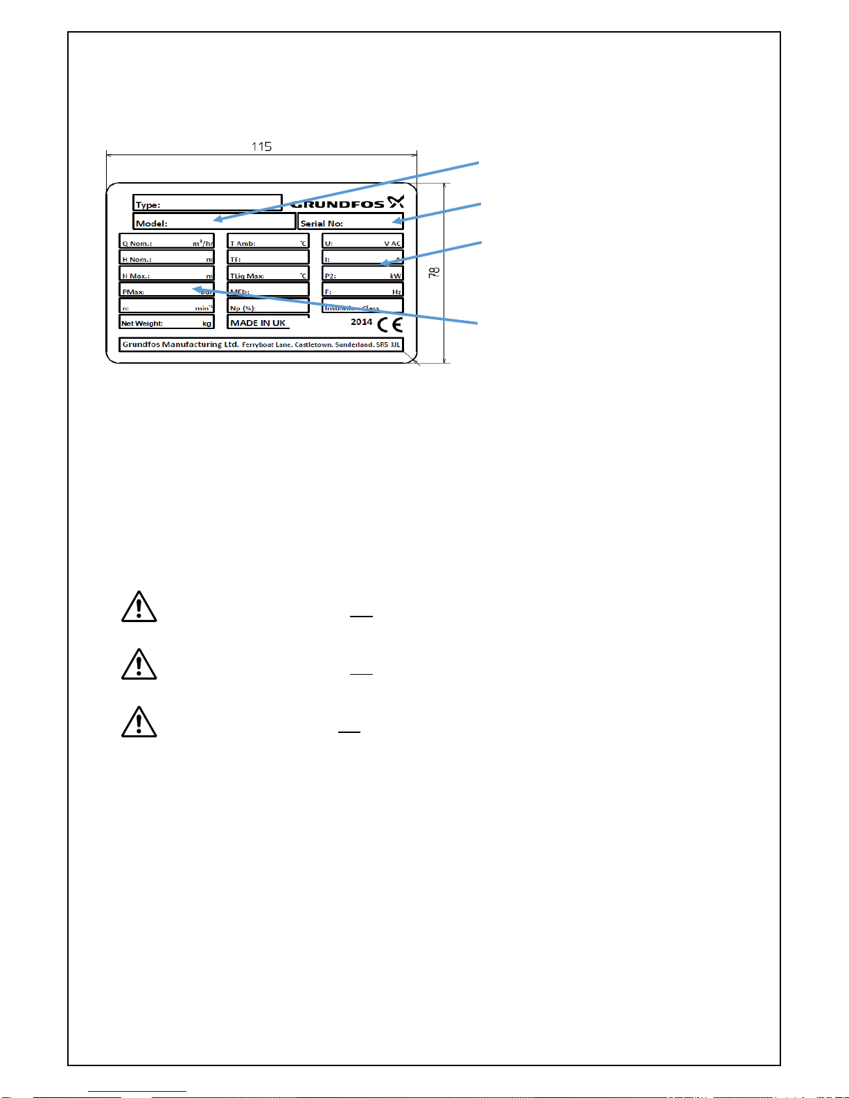
4.0 Product Identification.
The PHT unit has a silver label attached to the cabinet.
This label gives the following key information.
Fig. 1 – Product Nameplate
5.0 Operating Principles.
The function of the PHT pressurization equipment is to continuously monitor the pressure within
hydronic pressurized heating and chilled water systems, maintaining the optimum operating
pressure through providing automatic pressurised water top when required to compensate for
system losses. (e.g. slow leaks, air venting, etc.).
The PHT equipment will also provide signals and alarms for connection to building management
systems.
The PHT equipment will not fill systems
The PHT equipment will not cope with major water loss.
(e.g. System drain down, burst pipe)
The PHT equipment is not intended to be used for water boosting applications
Please consult the appropriate datasheets for product selection
Three distinct types of unit are described in this document:
1. Standard Pressurisation Unit – Single and twin pump configurations
- Delivers water into a single system
2. Twin System Pressurisation Unit – Twin pump only
- Delivers water into two different systems
3. Glycol Pressurisation Unit - Twin pump only
- Delivers a mix of water and glycol into a single system
Part no.
Serial no.
Electrical data
Hydraulic data
Page 6

www.grundfos.co.uk
Page 5 of 47
GRUNDFOS INSTRUCTIONS
5.1 Standard Pressurisation Unit (PHT-N/D/F models).
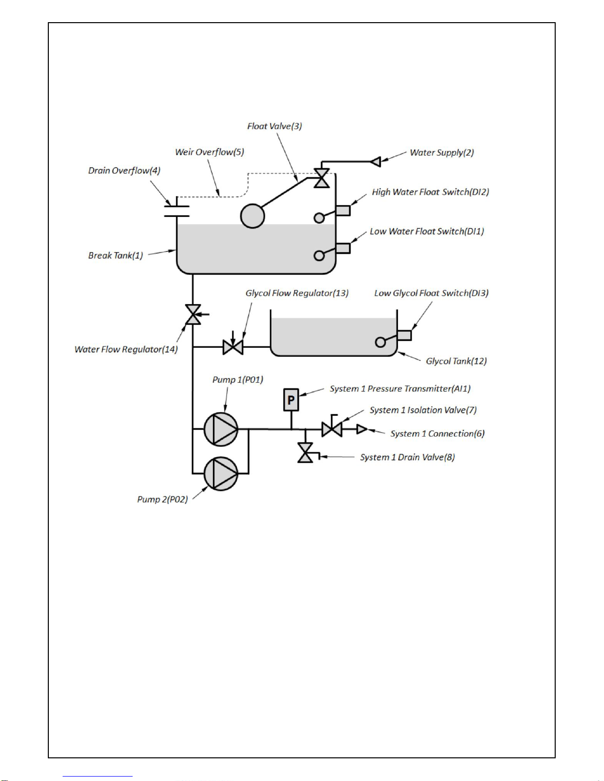
The following schematic shows the arrangement of the PHT-N/D/F pressurisation models:
Fig. 2 – PHT-N/D/F Schematic
The pressurisation unit is connected into the sealed system (System 1) through the System 1
Connection(6.
The System 1 Isolation Valve(7) provides a point to isolate the unit from the system.
The System 1 Drain Valve(8) provides a point to drain down the unit and/or system and for
commissioning purposes.
The System 1 Pressure Transmitter(AI1) measures the pressure in System 1.
The PHT unit can be configured with one or two pumps (P01 and P02) which when energised, will
transfer water from the Break Tank into System 1 to increase the pressure as required.
The pumps run in a duty/standby configuration where only one pump runs at a time (the duty
pump). The duty pump will always be the pump with the least accumulated total run time. This is a
measure to spread the wear evenly between the two pumps.
In single pump units Pump 1(P01) permanently acts as the duty pump.
A Current Sensor(AI5) (not shown on schematic), measures the electrical current consumption of
Pump 1(P01) and Pump 2(P02) to detect faults in the pumps.
A System 1 Fault Output(DO1) (not shown on schematic) is used to interlock the boiler or chiller on
System 1 to disable it if the system pressure falls outside of safe operating limits.
A General Fault Output(DO2) is provided to signal any fault presented by the unit.
Three additional outputs are provided which can be customised to signal a range of specific faults
or functions, Programmable Output 1(DO6), Programmable Output 2(DO7) and Programmable
Output 3(D08).
The pressurisation unit is fitted
with a Break Tank(1) which is filled
from the Water Supply(2), via a
Float Valve(3). The break tank is
fitted with a Drain Overflow(4) in
case the Break Tank overfills, and a
Weir Overflow(5) in case the Drain
Overflow becomes blocked.
A Low Water Float Switch(DI1) is
fitted to detect a low water
condition.
A High Water Float Switch(DI2)
(optional extra) is fitted to detect
overfilling of the tank.
Page 7

www.grundfos.co.uk
Page 6 of 47
GRUNDFOS INSTRUCTIONS
5.2 Twin System Pressurisation Unit (PHT-T models).
A variation of the design allows a single pressurisation unit to provide top-up for two systems,
referred to as a Twin System Pressurisation Unit.
The following schematic shows the arrangement of a twin system pressurisation unit:
Fig. 3 – PHT-T Schematic
This design allows the pressurisation unit to provide top up to two systems independently, with
different parameters, using the same two pumps.
In addition to the features described for a standard pressurisation unit, the following additional
features are provided:
The pressurisation unit is connected into the second system (System 2) through the System 2
Connection(9) via the System 2 Isolation Valve(10), a manual valve provided for isolating the unit
from the system. The System 2 Drain Valve(11) is provided for draining down the unit and/or
system and for commissioning purposes.
The System 2 Pressure Transmitter(AI2) measures the pressure in System 2.
The System 1 Valve(DO3) directs flow from the pumps into System 1.
The System 2 Valve(DO4) directs flow from the pumps into System 2.
When used in twin system mode the Programmable Output 3(DO8) is set to function as a
critical fault output for system 2 by default and cannot be changed.
Page 8
www.grundfos.co.uk
Page 7 of 47
GRUNDFOS INSTRUCTIONS
5.3 Glycol Pressurisation Unit (PHT-V model).
Another variation of the design allows the unit to deliver a predetermined mix of water and glycol
into a single system.
The following schematic shows the arrangement of a glycol pressurisation unit:
Fig. 4 – PHT-V Schematic
In addition to the features described for a standard pressurisation unit, the following additional
features are provided:
Glycol is held in the Glycol Tank(12). The Low Glycol Switch(DI3) detects when the glycol has run
out and requires refilling.
When the pumps run, they draw a predetermined mix of water and glycol out of the two break
tanks.
The ratio of water to glycol is set by manually adjusting the Glycol Flow Regulator(13) with respect
to the Water Flow Regulator(14).
Page 9

www.grundfos.co.uk
Page 8 of 47
GRUNDFOS INSTRUCTIONS
6.0 General information.
6.1 Delivery and handling.
The PHT unit is supplied from the factory in either a cardboard box (PHT-N) or a
plastic bag (All other models) which will be strapped to a wooden pallet suitable
for handling by forklift equipment or similar.
The weight and size of the PHT unit may require the use of proprietary lifting equipment to be
handled safely. Please observe the weight indicated on the box label before selecting lifting
method.
Do not stack items on top of the box.
Do not drop the pallet/unit
6.2 Delivery inspection upon receipt.
The PHT should be immediately unpacked and inspected.
Any damage must be reported to the supplier within seven days in writing or sooner.
It is important that this Installation and Operating manual is studied carefully before any
installation takes place. The installation and operation should also be in accordance with local
regulations and accepted codes of practice.
Under no circumstances should the unit be operated until correctly installed in the
system pipework and ensure that the controller cover and product cover are secured
in their appropriate positions.
6.3 Warranty.
1. The Grundfos warranty covers all defects within the PHT originating from faulty
workmanship and/or materials for a period of two years from the date of installation or
thirty months from the date of dispatch from the factory, whichever is the shorter.
2. The warranty covers the replacement of any faulty parts and our labour cost to replace the
faulty parts. It does not cover the cost of removing, returning and refitting the PHT unit or any
secondary losses arising from the failure.
3. Under no circumstances should faulty equipment be dismantled. Failure to comply with this
instruction could invalidate the warranty.
4. Defects arising from incorrect installation, water containing debris, or harmful chemicals,
inadequate electrical protection, faulty ancillary equipment, lightning or other circumstances
beyond our control, are not covered by the warranty.
6.4 Site storage on receipt.
It is strongly recommended once the PHT unit has been delivered to site, that it is placed
immediately into a dust, moisture and frost-free area which has been secured to prevent
unauthorised interference. If this is not possible then the unit should be stored in an area which
is as near as possible to the ideal storage conditions as described above.
Page 10
www.grundfos.co.uk
Page 9 of 47
GRUNDFOS INSTRUCTIONS
6.5 Weather, Temperature and long term storage.
The PHT unit needs to be protected against the weather and extremes of temperature during
summer and winter. Provision to maintain the PHT’s operating conditions needs to be made
within the overall system design and location setting.
The PHT unit must be protected from freezing conditions. Should the unit be placed outside then
the unit needs to be protected against the weather and consideration must be made for trace
heating and/or lagging.
The PHT unit must be protected from heat. Should the unit be placed in an environment that could
potentially become hotter than the operational recommendations then air venting and circulation
must be considered.
If the PHT unit is being stored during periods of frost the whole unit should be drained to
avoid damage. Remove all drain and vent plugs and allow the unit to drain.
Do not replace the plugs until the PHT unit is to be used again.
6.6 Operating Environment.
The PHT unit must not be used in an environment which has been classified as
hazardous where it could provide a source of ignition and therefore cause an explosion by
flame path.
Grundfos do not accept any responsibility for the use of the PHT unit to pump liquids which
could be construed as being hazardous to health either by touch, ingestion or inhalation of
fumes or gases given off by the liquid.
6.7 Installation Location.
Careful consideration must be given to the location of the PHT unit.
The following are minimum requirements:
The PHT unit should ideally be placed in a location where the control panel and status LED can
readily be seen and the internal buzzer heard without obstruction.
These are primary warning and alarm events and should be available to be observed and heard.
The pump must be vented/primed before it is started again.
Refer to the commissioning section.
The PHT may be located outdoors in a weather, frost and rodent proof enclosure with
adequate ventilation especially during hot weather. All pipe work subject to freezing
conditions must be adequately protected. Alternative system provision must be
made for alerting the inhabitants to the PHT warnings and alarms.
Page 11

www.grundfos.co.uk
Page 10 of 47
GRUNDFOS INSTRUCTIONS
To enable maintenance and service of the PHT unit to be carried out satisfactorily,
the area should have adequate lighting for this work to be carried out safely.
Ensure that the PHT is positioned to allow access for examination and service.
Allow the following:
A minimum of 50 cm should be left above all units.
A minimum of 50 cm should be left to the system connection side of all units.
A minimum of 100 cm should be left at the front of the unit.
Adequate drainage facilities and protection from water damage in the immediate
vicinity of the PHT unit must be provided.
If the PHT unit is installed into a roof spaces, then provisions should be made for the
small level of vibration associated with any rotating equipment in case it causes
disturbance. Provision should also be made for drainage of the unit, leakage and any loss of water
during commissioning and service.
The PHT unit should not be installed in an unventilated small space, ensure
adequate ventilation for the motor.
6.8 General requirements.
The installation pipework may need to be properly supported
before being connected to the PHT unit so that the PHT unit is not stressed.
The pipework installation to and from the PHT unit should be in accordance with local
water authority regulations, best industry practice and according to any design
recommendation
The electrical installation of the PHT unit should be in accordance with the latest issue of
the I.E.E. regulations and performed by a competent installer.
The equipment must be Earthed
Page 12
www.grundfos.co.uk
Page 11 of 47
GRUNDFOS INSTRUCTIONS
6.9 Operating Conditions.
Electrical supply: 230 V +10 /-6%, 50 Hz
Electrical load:
Model
Power (Watts)
Full Load current (Amps)
PHT-N130/PHT-N230
28 W
0.12 A
PHT-D125/PHT-D225
410 W
1.83 A
PHT-D150/PHT-D250
900 W
3.94 A
PHT-F125/PHT-F225
410 W
1.83 A
PHT-F150/PHT-F250
900 W
3.94 A
PHT-F180/PHT-F280
1150 W
5.2 A
PHT-T225/PHT-V225
410 W
1.83 A
PHT-T250/PHT-V250
900 W
3.94 A
Quiescent All models
15 W
0.07 A
Pollution Degree: 3 Noise level: <70 dB(A) at full speed
Liquid temperature range: +1°C to +60°C Ambient temperature: From +1°C to 40°C
Relative humidity: 95% (non-condensing)
Usage: Indoor (Outdoor, subject to restrictions found)
Type of protection: Class 1 (earthed) equipment
Equipment type: Stationary, fixed equipment
Construction type: Fixed construction, no moveable parts
EMC Environment: B (light industrial, commercial and residential)
Inlet pressure max: 3 bar
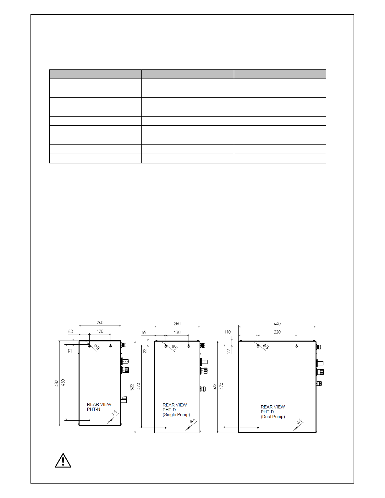
6.10 Wall Fixings.
All units must be mounted/stood in the vertical position.
The PHT-N and PHT-D units are suitable for wall fixing.
The wall fixing dimensions are given below.
Fig 5. – Wall fixing dimensions
Refer to the Product weight table also.
Page 13
www.grundfos.co.uk
Page 12 of 47
GRUNDFOS INSTRUCTIONS
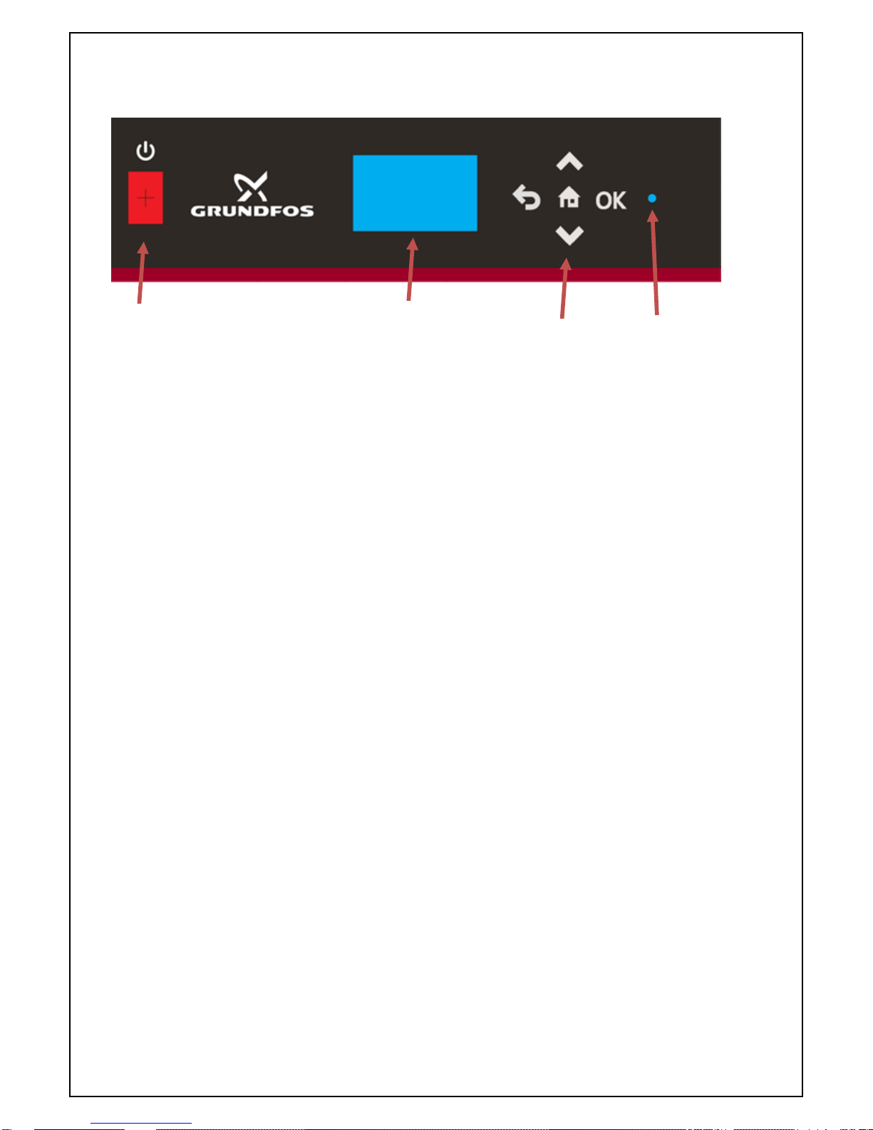
7.0 System Controller overview.
The front face of the PHT controller has the following items.
Fig 6. - Controller front screen
The ON/OFF Switch is an illuminated switch indicating that the unit is powered ON/OFF.
The Display panel gives the Status of the unit, the current pressure, the Date and time when
operating without a fault. When operating with a fault the Status will indicate the fault detected.
The Display panel will auto-dim to save energy after a predefined period without operation.
The Keypad has:
UP/DOWN arrow keys used to move between pages and increase/decrease values.
Home Key to return to the Home page
OK key to confirm a value entered/Access the password protected menu’s
Return key to step back in the program
The Status LED gives a quick and easy Status for the unit.
Green – Status Healthy
Red – Status Fault
The system status is also supported by an audible buzzer.
The buzzer activates with Critical faults and can be silenced by pressing and holding the OK key.
7.1 Programming the PHT Controller.
The PHT controller has a simple, intuitive and ergonomic design that is easy to pick up.
Fixed combination volt free outputs that allow critical and general fault monitoring.
Programmable outputs provide complete flexibility.
The controller can communicate with the Grundfos range of CIM modules providing protocol
support for BACnet, Modbus and others.
ON/OFF Switch
(Illuminated when ON)
Display panel
Keypad
Status LED
Page 14
www.grundfos.co.uk
Page 13 of 47
GRUNDFOS INSTRUCTIONS
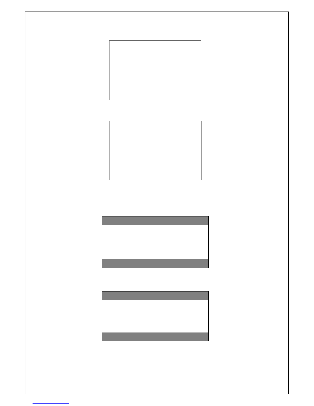
7.2 Start-Up Sequence.
Upon powering up the unit, the controller shall display the below for 3 seconds:
PHT-*
Grundfos
14.25
The screen will then show the software version of the unit for a further 3 seconds:
Software Version
V1.0.0
7.3 Main Operating Screen.
When the unit is operating normally and the status is healthy the display will include:
Status: OK / System 1 Pressure and value / Current Date and Current Time:
Status: OK
System 1 Pressure 1.5 Bar
23/08/2017
14.25
With the PHT-T configuration, the display will also show System 2 Pressure and value:
Status: OK
System 1 Pressure 1.5 Bar
System 2 Pressure 2.0 Bar
23/08/2017
14.25
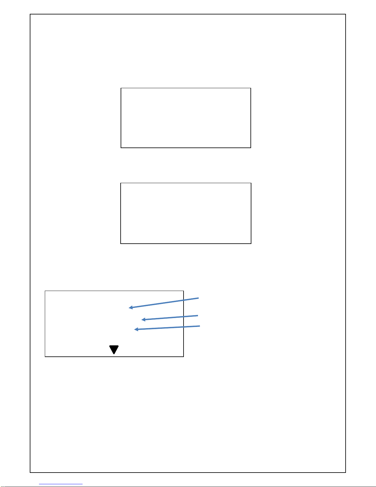
If a fault condition is active, then the Status will show FAULT and the line below will carry a
message indicating the fault. If more than one fault exists then the first detected fault is shown
until cleared. The next fault is then displayed:
Page 15

www.grundfos.co.uk
Page 14 of 47
GRUNDFOS INSTRUCTIONS
Status: FAULT
Low Water
System 1 Pressure 1.5 Bar
23/08/2017
14.25
If a pressure sensor fault has been registered, then no pressure reading will be shown:
Status: FAULT
Sensor
System 1 Pressure Bar
23/08/2017
14.25
If the unit requires servicing, then the Status will show SERVICE:
Status: SERVICE
System 1 Pressure 1.5 Bar
23/08/2017
14.25
If a fault is present and a service is required, then the Status will show FAULT - SERVICE:
Status: FAULT - SERVICE
Sensor
System 1 Pressure Bar
23/08/2017
14.25
7.4 Menu Entry.
To enter the password protected menus press and hold down the OK button for three seconds
The screen will prompt for a 4-digit numeric password:
Enter Password
_ _ _ _
User Password: 4321
Page 16
www.grundfos.co.uk
Page 15 of 47
GRUNDFOS INSTRUCTIONS
Use the UP/DOWN arrow keys to get to the required number before pressing the OK key to
confirm. When the OK key is pressed the cursor moves onto the next character.
If the user enters an incorrect password the following screen is displayed for 3 seconds before
returning to the main screen:
Incorrect Password!
If the user enters a correct password, then the relevant access granted message will be shown for 2
seconds before progressing into the menu system:
Example:
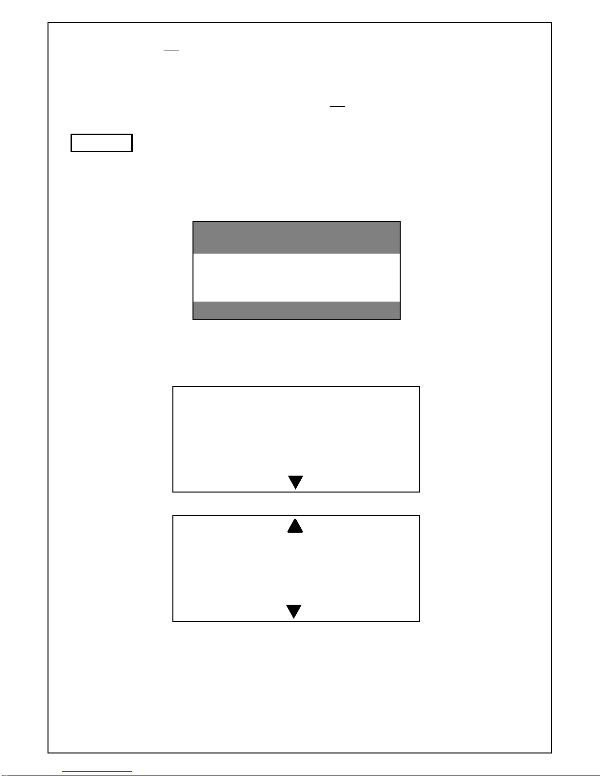
7.5 Menu System.
The menu system opens at the first page in navigate mode.
The arrow at the bottom of the screen indicates that there are further pages.
01
Current Time:
14:25
To enter the edit mode and edit the value press the OK key, the cursor will appear, use the
UP/DOWN keys to change the value. Confirm the new value by pressing OK key.
If the value has two fields then the cursor will automatically move to the next field.
If the page has an arrow at the top, this indicates that there are preceding pages
Once the value of the last field has been confirmed the menu system will return to the navigation
mode. Repeat these operations for all parameters requiring change.
The final screens in the menu allow for the manual operation of the pump(s) via pressing and
holding the OK button. This will activate the pump(s) while the button is held down and is only
active in the Engineering menu.
User Access
granted
Parameter
Value
Page number
Page 17
www.grundfos.co.uk
Page 16 of 47
GRUNDFOS INSTRUCTIONS
The parameters will not come into effect until the Menu system has been exited.
To exit the menu system, press the Home key.
If no buttons are pressed for 5 minutes, then the system will automatically return to the operating
screen. If there are any pending edits (value changed but not confirmed) then the change will be
discarded.
Not all parameters are available for Edit in the User menu.
Please see the table below.
7.6 Fault Indication.
The presence of an active fault condition will be shown on the operating screen:
Status: FAULT
Sensor
System 1 Pressure Bar
23/08/2017
14.25
Pressing the Down key will take the operator straight into the list of current faults.
The fault number is displayed, along with the name of the fault, relevant value (if applicable),
date and time. The presence of the arrow indicates further fault pages.
The operator can scroll through the list of faults, clearing them with the OK key.
Once a fault has been acknowledged it will disappear from the list.
Once all faults have been acknowledged (or a timeout period of 3 minutes has elapsed) then
the controller will return to the operating screen. If the fault is cleared but still detected as
present then the fault message and status return, with a new date and time stamp.
01
SENSOR
23/08/2017 14:25
02
HIGH PRESSURE 2.9 Bar
14/07/2017 11:30
NOTE
Page 18

www.grundfos.co.uk
Page 17 of 47
GRUNDFOS INSTRUCTIONS
7.7 Fault Log.
The controller will log a minimum of 30 historic fault conditions in non-volatile memory.
This includes faults that have been acknowledged via the operating screen.
Access to the list of stored faults is through the Engineers menu.
Faults can be cleared from the list.
7.8 Uploading the Fault Log.
The Fault log can be upload to a memory stick at any time by simply inserting a standard size
USB memory stick into the USB port found on the reverse of the display unit.
Wait approximately 5 seconds, observe the Status LED on the front panel changing colour
and returning to its previous state, then remove the USB stick. The Fault log outputs a simple
text file. Example below:
Fault 41 of 43
Fault Type - System1 Low Pressure
Date - 09/06/2017
Time - 08:13
7.9 Programmable Outputs.
The PHT controller has three programable digital outputs.
These outputs are designated
Programable output 1 – Physical naming D06
Programable output 2 - Physical naming D07
Programable output 3 - Physical naming D08
These outputs can be programmed with one or as many of the fault options as needed.
Programmable Output 1(DO6), Output 2 (DO7) and Output 3 (DO8).
With PHT-N/D/F/V units the above outputs can programmed to be activated by any combination of
the following faults:
• Pump 1 Over Current
• Pump 1 Under Current
• Pump 2 Over Current
• Pump 2 Under Current
• Low Water
• High Water
• Low Glycol
• Service Required
• System 1 Flood Protection
• System 1 Excessive Consumption
• System 1 Low Pressure
• System 1 High Pressure
• System 1 Sensor Fault
• Pump 1(P01) running
• Pump 2(P02) running
• Pump 1(P01) or Pump 2(P02) running
Refer to Fig. 7
Page 19

www.grundfos.co.uk
Page 18 of 47
GRUNDFOS INSTRUCTIONS
With the PHT-T unit, the following eleven faults are added to the above list for Output 1(DO6)
and Output 2 (DO7)
• System 2 Flood Protection
• System 2 Excessive Consumption
• System 2 Low Pressure
• System 2 High Pressure
• System 2 Sensor Fault
• Topping up System 1
• Topping up System 2
• Valve 1 Over Current
• Valve 1 Under Current
• Valve 2 Over Current
• Valve 2 Under Current
With the PHT-T unit, Output 3(DO8) becomes System 2 Interlock reporting the following:
• System 2 Low Pressure Alarm
• System 2 High Pressure Alarm
• System 2 Sensor Fault
• Mains Power failure
These are the conditions under which the boiler or chiller on System 2 must be disabled.
The fault buzzer will cycle between ON for 5 seconds and OFF for 10 seconds continuously until muted by
pressing and holding the OK button for 2 seconds.
To program these outputs:
1 - Enter the Engineers menu and navigate to Programmable output pages.
2 - Enter the edit mode by pressing the OK button.
3 - Use the UP and DOWN keys to navigate the list of faults that can be programmed
4 - When the desired fault is at the top of the stack press OK, this will select the fault.
5 - Select any further fault outputs as required.
6 – Exit the menu by pressing the Home key.
Fig. 7 – Location of programmable outputs
Page 20

www.grundfos.co.uk
Page 19 of 47
GRUNDFOS INSTRUCTIONS
7.10 Digital Outputs.
All of the fault outputs can be wired as Normally Closed or Normally Open.
(refer to Connection diagram)
7.11 System 1 Interlock Output(DO1) is activated by all/any of the following alarms:
• System 1 Low Pressure
• System 1 High Pressure
• System 1 Sensor Fault
• Mains Power failure
These are the conditions under which the boiler or chiller on System 1 must be disabled.
The fault buzzer will cycle between ON for 5 seconds and OFF for 10 seconds continuously until muted by
pressing and holding the OK button for 2 seconds.
7.12 General Fault Output(DO2) is activated by all/any of the following alarms:
• Pump 1 Over Current
• Pump 1 Under Current
• Pump 2 Over Current
• Pump 2 Under Current
• Low Water
• High Water
• Low Glycol
• System 1 Flood Protection
• System 2 Flood Protection
• System 1 Excessive Consumption
• System 2 Excessive Consumption
• System 1 Low Pressure
• System 1 High Pressure
• System 1 Sensor Fault
• System 2 Low Pressure
• System 2 High Pressure
• System 2 Sensor Fault
The user may choose to disable the boiler or chiller on System 1.
Page 21

www.grundfos.co.uk
Page 20 of 47
GRUNDFOS INSTRUCTIONS
8.0 Installation and commissioning – General.
The PHT unit has been designed to minimize and simplify the number of installation and
commissioning activities required to bring the system on line.
The PHT unit MUST be Earthed.
All mechanical connections should be carried out by a by a qualified and authorised
person in accordance with this manual and the latest codes of practice.
Do not attempt to start the pump even to check the direction of rotation until the system
has been filled with water and both the pump and the system have been primed/vented.
Running the pump dry may permanently damage it. This will not be covered by warranty.
See the Pump Priming section.
Do not remove the controller enclosures, controller components, motor terminal box
cover, electrical cables or any other electrical protective covering without first ensuring
that the electrical supply is suitably isolated and cannot be switched back on.
Do not attempt to supply electricity to the PHT unit and run the pump electric motor
without ensuring that all electrical fittings, cables and enclosures are intact and suitably
electrically isolated from human touch during operation.
Do not attempt to supply electricity to the electric motor or re-pressure the pipe work
system without first ensuring that all protective coverings are held securely in their
correct positions.
The PHT unit and any expansion vessel should be connected on the system
return. Non-return valves and RPZ valves should not be connected between the PHT
unit and the system.
It is strongly recommended that all PHT units are connected to a lockable isolator.
Backup fuse/MCB protection should be sized at 20 Amps
NOTE
NOTE
All electrical connections should be carried out by a qualified and authorised electrician
in accordance with the wiring diagram supplied within this manual and the latest I.E.E.
regulations.
Ensure that the PHT unit is electrically isolated before removing any covers.
Any cables supplied to the volt free contacts may be supplied from another source
and may remain live after the PHT unit is isolated. These must be isolated elsewhere.
The PHT controller has static sensitive components and standard static
precautions must be taken when working with the controller
Page 22

www.grundfos.co.uk
Page 21 of 47
GRUNDFOS INSTRUCTIONS
8.1 PHT-N/D/V unit – Float valve adjustment.
The PHT-N unit must be fitted with a filter and depending on the site mains water
pressure a flow restrictor. This filter and flow restrictor are inserted into the mains
water fill valve, filter section first as shown below.
Failure to do so may result in damage to the PHT-N unit
Two different flow restrictors are supplied, to be used as per the table below:
Mains Water Pressure
Requirements
Below 1 Bar
Filter only
Between 1 and 4 Bar
Filter and Low Pressure Restrictor (Blue)
Above 4 Bar
Filter and High Pressure Restrictor (White)
Fig. 8 PHT-N/D/V – Float valve filter and flow restrictor
Fig. 9 PHT-N/D/V – Float valve filter and flow restrictor and level adjustment
Adjusting the water shut off level.
Insert the float spiral stem horizontally between the two lower jaws and twist to engage upper jaw.
Turn on the water supply.
Allow the break tank to fill.
Adjust water fill level, twisting float up or down until the water shut off level is just below the
Overflow.
Direction of filter
insertion
Page 23

www.grundfos.co.uk
Page 22 of 47
GRUNDFOS INSTRUCTIONS
8.2 PHT-F/T unit – Float valve adjustment.
Fig. 10 PHT-F/T – Float valve level adjustment
8.3 Priming of the Pumps and System.
All PHT-D/F/T/V pumps must be primed before the PHT unit is switched ON.
Permanent damage can occur from dry running the pumps.
To Prime:
Loosen the priming screw(s) located on the pump housing, system manifold(s) until water
flows through the priming screw.
Tighten the priming screw back up.
Dry off any water.
Fig. 11 – PHT-*25 and PHT-*50 Models Fig. 12 – PHT-*80 Model
Fig. 13 System priming
Priming Screws
Locations
Set the ball float valve to its lowest
position on the valve arm.
Allow the tank to fill from the mains
water supply and check that the stop fill
level does not exceed the Overflow and
sit just below the Overflow.
Adjust as necessary.
Page 24

www.grundfos.co.uk
Page 23 of 47
GRUNDFOS INSTRUCTIONS
8.4 Installation checklist.
During the installation phase:
DO NOT apply mains power
to the unit. DO NOT apply
water to the unit.
Step
Done
Activity
Action/Check/Note
1
Fully read and study this manual.
2
Unpack, inspect for completeness and any damage.
Report to
supplier/customer
3
Ensure that the installation location meets all of the
requirements in this manual.
4
Transport the unit to the chosen location.
Caution - handling
5
Test location of unit for fit and access, remove unit.
6
Make wall/floor fixings.
If required
7
Remove the screws retaining front cover.
Remove front cover. Place to one side.
8
Locate unit and fasten down unit as required.
9
Make the mains water supply connection to the float valve.
Do not turn on
water.
Isolation valve
10
Make the PHT to system connections.
Do not turn on
water.
Isolation valve
11
Make the overflow connection to drain.
12
Remove the screws retaining the top cover of the controller
and open.
Wiring diagram found in this
manual
13
Wire mains supply from isolator to connector block
through side wall M20 cable gland.
Perform continuity
check.
Label wires. System must be
14
Wire digital outputs through side wall grommet, through
side wall gromit and to connector blocks on PCB
(as required). Do not apply any voltages.
Wiring diagram found
in this manual.
Perform continuity
check
Label wires
15
Re-fit the controller front panel
16
Review all of the above actions, if the commissioning
phase does not follow immediately after, replace the
covers and screws. Leave the unit in a safe condition
Leave Isolated electrically
and hydraulically
17
System is ready to commissioning
Observe static sensitive precautions!
Observe static sensitive precautions!
Page 25

www.grundfos.co.uk
Page 24 of 47
GRUNDFOS INSTRUCTIONS
8.5 Commissioning checklist.
Before the commissioning phase starts ensure that the Installation checklist has
been completed and check the state of the mains power and water supplied to
the unit.
Step
Done
Activity
Action/Check/Notes
1
Fully read and study this manual.
2
Ensure that the installation location meets all of the
requirements in this manual.
3
Check mains power and water to the unit are both OFF
Ensure both are OFF and cannot be
accidentally turned ON.
4
If necessary, remove the screws retaining front and
top covers. Place to one side.
5
Inspect the Installation, check everything in the
Installation checklist has been completed.
6
Close the system isolating valve on the discharge side of
unit. Open the mains water isolating valve. Apply water
to the unit and check the filling of the header tank.
Refer to the Float valve
adjustment section
7
Check the fill level in the header tank does not exceed the
overflow height. Make any adjustments as required.
Refer to the Float valve
adjustment section
8
Prime the pump and the whole system as necessary.
Inspect for any leaks.
Refer Priming pump section of this
manual.
9
Refit the controller cover and review all of the above
actions. Apply the mains power. Switch ON the unit.
10
Allow the unit to boot up.
Ignore any Warnings/Alarms.
The PHT-T model will need one
minute to close all motorized valves
before you can begin to program the
unit.
11
Access the Engineers menu.
Refer System Controller overview
section
12
Set the unit up according to the desired customer
parameters.
Record the parameters in the
Commissioning log.
13
Test the pumps, using the Pump test function in the
engineering menu. Open the system isolating valve.
Press and hold down the OK but for
the duration of the pump run.
Check the system for any faults.
Observe correct system operation.
13
Replace all covers and re-fit the screws
Observe static sensitive precautions!
Page 26

www.grundfos.co.uk
Page 25 of 47
GRUNDFOS INSTRUCTIONS
15
Clean up area and ensure safe for user, All
Isolating valves are in the OPEN position
Clear any faults/system run time history
16
System is ready for operation
Update the history log at back of
this manual
Page 27
www.grundfos.co.uk
Page 26 of 47
GRUNDFOS INSTRUCTIONS
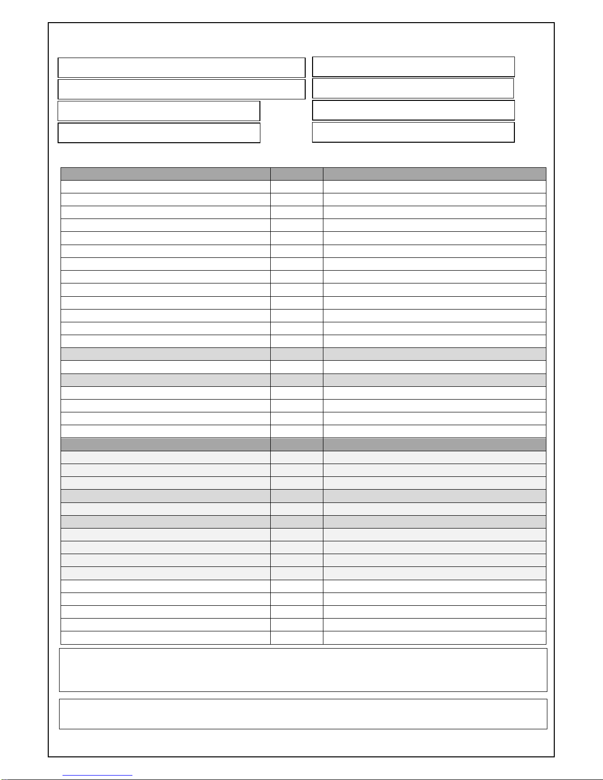
8.6 Commissioning Record.
8.7 Settings Record.
Common Settings
1 Current Time
HH:MM (24 hr)
2 Current Date
DD/MM/YYYY
3 Service Reminder
ON/OFF
4 No. of Pumps
1 / 2
5 Pump Anti-seize
ON/OFF
6 Pump Anti-seize Period
Days
10 Pump Trip delay
Seconds
11 Pressure Alarm delay
Seconds
12 Low Water Reset Time
Seconds
13 System 1 Set Pressure
Bar
14 System 1 Differential Pressure
Bar
15 Common Differential
YES/NO
16 System 1 Low Pressure Alarm ON
Bar
17 System 1 Low Pressure Alarm OFF
Bar (Only if Common Differential = NO)
18 System 1 High Pressure Alarm ON
Bar
19 System 1 High Pressure Alarm OFF
Bar (Only if Common Differential = NO)
20 System 1 Pump Hold OFF Time
Seconds
21 System 1 Pump Run ON Time
Seconds
22 System 1 Flood Protection
Mins/Hour
23 System 1 Excessive Consumption
Starts/Month
Additional PHT-T Settings
24 System 2 Set Pressure
Bar
25 System 2 Differential Pressure
Bar
26 System 2 Low Pressure Alarm ON
Bar
27 System 2 Low Pressure Alarm OFF
Bar (Only if Common Differential = NO)
28 System 2 High Pressure Alarm ON
Bar
29 System 2 High Pressure Alarm OFF
Bar (Only if Common Differential = NO)
30 System 2 Pump Hold OFF Time
Seconds
31 System 2 Pump Run ON Time
Seconds
32 System 2 Flood Protection
Mins/Hour
33 System 2 Excessive Consumption
Starts/Month
44 Software Version
47 Programmable output 1
48 Programmable output 2
49 Programmable output 3
CIM Card Installed
YES/NO
Site Ref:
Date:
Model:
Company:
Serial no:
Engineer:
PU Ref:
Contact no:
Notes:
Engineers Signature: Customers Signature:
Date: Date:
Page 28

www.grundfos.co.uk
Page 27 of 47
GRUNDFOS INSTRUCTIONS
9.0 User maintenance.
There are NO user serviceable parts in the PHT unit.
9.1 Planned Preventative Maintenance.
It is highly recommended that the PHT equipment is maintained in line with the
Grundfos Services Planned Preventive Maintenance regime for this equipment.
A Grundfos Service contract can be taken out to cover this.
For a copy of the regime and to discuss a Grundfos Service contract, contact:
Grundfos Pumps Ltd.,
Telephone: +44 (0) 1525 850 000
9.2 Annual Service.
Along with the Preventative Maintenance regime Grundfos recommends that the PHT unit is serviced,
inspected and tested every twelve months.
For a copy of the Annual Service regime and to discuss a Grundfos Service contract, contact:
Grundfos Pumps Ltd.,
Telephone: +44 (0) 1525 850 000
This ensures that the system remains in first class working order.
The PHT unit should be serviced and tested annually by a suitably qualified and competent person.
Should any maintenance work be required then the water and electricity supply may
require isolating prior to commencing work.
The building will be without the protection that the PHT unit gives during this period and
alternative measures should be considered.
Ensure any outgoing signals from the PHT unit are not going to cause activation of:
o Alarms/beacons/BMS Control panel or Boiler shut down
o Any other warning/monitoring devices installed (eg. SMS to mobile device)
o External voltages may be present on Digital inputs.
(these must be isolated before commencing work on them)
NOTE
Page 29
www.grundfos.co.uk
Page 28 of 47
GRUNDFOS INSTRUCTIONS
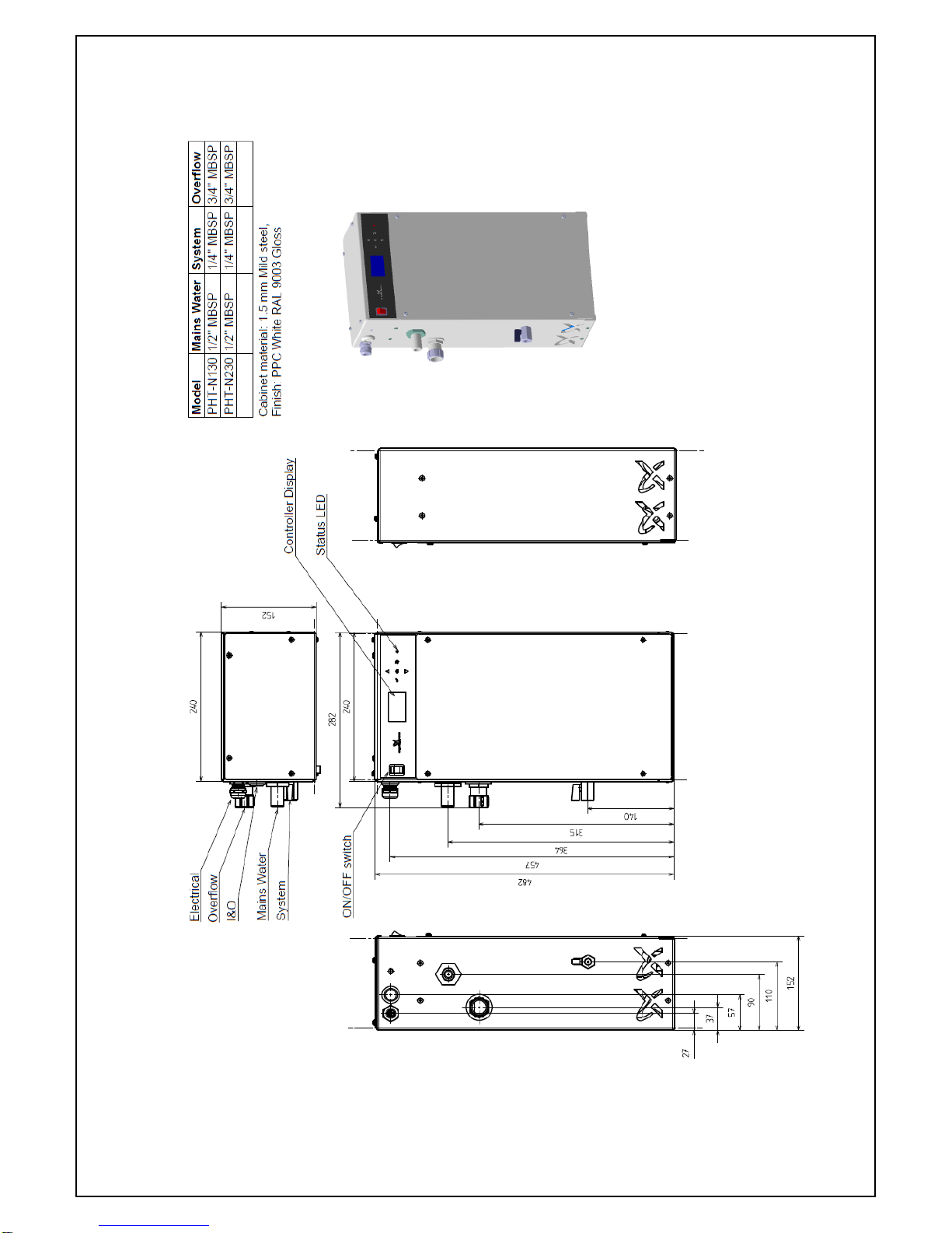
10.0 Technical drawings.
10.1 Product Drawing – PHT-N.
Page 30

www.grundfos.co.uk
Page 29 of 47
GRUNDFOS INSTRUCTIONS
10.2 Product Drawing – PHT-D (Single pump).
Page 31
www.grundfos.co.uk
Page 30 of 47
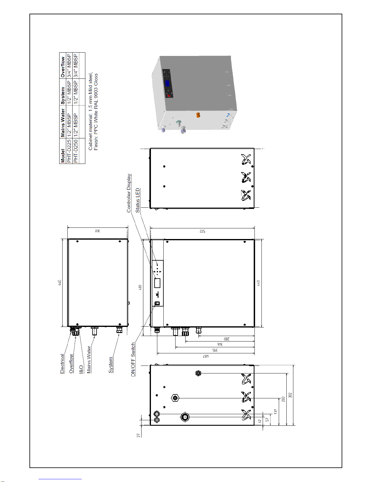
GRUNDFOS INSTRUCTIONS
10.3 Product Drawing – PHT-D (Dual pump).
Page 32

www.grundfos.co.uk
Page 31 of 47
GRUNDFOS INSTRUCTIONS
10.4 Product Drawing – PHT-F.
Page 33

www.grundfos.co.uk
Page 32 of 47
GRUNDFOS INSTRUCTIONS
10.5 Product Drawing – PHT-T.
Page 34

www.grundfos.co.uk
Page 33 of 47
GRUNDFOS INSTRUCTIONS
10.6 Product Drawing – PHT-V.
Page 35

www.grundfos.co.uk
Page 34 of 47
GRUNDFOS INSTRUCTIONS
10.7 Connection drawing.
Page 36

www.grundfos.co.uk
Page 35 of 47
GRUNDFOS INSTRUCTIONS
10.8 Wiring Diagram.
Page 37

www.grundfos.co.uk
Page 36 of 47
GRUNDFOS INSTRUCTIONS
10.10 Pump Set Fill Pressures.
10.11 PTH-V Glycol settings.
The PHT-V unit is factory set to dose Glycol @ 20 %, Water @ 80%.
This can be adjusted according to the below table.
Maximum Glycol dose is 50 %.
Glycol Concentration
Glycol valve setting
Water valve setting
1 %
0.05
6.2
5 %
0.1
6.1
10 %
0.2
6.0
15 %
0.3
5.9
20 %
0.7
5.7
25 %
1.0
3.1
30 %
1.3
2.8
Pump set
Closed Valve Head
(Bar)
Cold Fill Pressure
(Bar)
PHT-N230
4.0
3.0
PHT-D/F/T/V*25
3.80
2.5
PHT-D/F/T/V*50
6.4
5.0
PHT-F*80
10.0
8.0
Page 38

www.grundfos.co.uk
Page 37 of 47
GRUNDFOS INSTRUCTIONS
11.0 Spare Parts List.
Part no.
Description
Parts included
99366896
Kit, PHT-N*30 Pump
PHT-N*30 Pump, I&O manual
99366897
Kit, PHT-D/F/T/V*25 Pump
PHT-D/F/T/V*25 Pump, I&O manual
99366898
Kit, PHT-D/F/T/V*50 Pump
PHT-D/F/T/V*50 Pump, I&O manual
99366899
Kit, PHT-F*80 Pump
PHT-F*80, I&O manual
99366900
Kit, PHT- All Fuse kit
Full fuse set, I&O manual
99366901
Kit, PHT Front panel membrane
Front panel membrane, I&O manual
99366902
Kit, PHT ON/OFF Switch
ON/OFF Switch, I&O manual
99366903
Kit, PHT N/D/F/V Controller
PHT Controller, I&O manual
99366904
Kit, PHT Pressure transducer
Pressure transducer and cable, I&O manual
99366905
Kit, PHT Float switch
Float switch and cable, I&O manual
99366906
Kit, PHT-T Motorised ball valve cpl.
Motorised ball valve cpl., I&O manual
99366907
Kit, PHT BACNET card
BACNET Card, fixings and cover, I&O manual
99366908
Kit, PHT-V Manifold
PHT-V Manifold, I&O manual
99366909
Kit, PHT-T Manifold
PHT-T Manifold, I&O manual
99366910
Kit, PHT-T/V None-return valve
Non-return valve, I&O manual
99366911
Kit, PHT-D Hose kit
PHT-D Hoses, I&O manual
99366912
Kit, PHT-F Hose kit
PHT-F hoses, I&O manual
99366913
Kit, PHT-T Hose kit
PHT-T Hoses, I&O manual
99366914
Kit, PHT-V Hose kit
PHT-V Hoses, I&O manual
99366915
Kit, PHT-T Controller
PHT-T Controller, I&O manual
99366916
Kit, PHT N Float valve
PHT N Float valve, I&O manual
99366917
Kit, PHT Float valve & ball float
PHT Float valve &ball float, I&O manual
99366918
Kit, PHT I&O Manual
I&O Manual
99366919
Kit, PHT MODBUS card
MODBUS Card, fixings and cover, I&O manual
12.0 De-commissioning, Dismantling and Disposal.
The Hydronic heating/chilling system in the building will be without the protection that the
PHT unit gives once decommissioned and alternative measures to provide protection should
be considered. The owner of the building should be informed of this beforehand.
12.1 De-commissioning.
De-commissioning is the process of taking out of service the PHT unit.
Reasons for this could be:
Replacing with another unit
Upgrading the unit
Removing the system altogether
Page 39

www.grundfos.co.uk
Page 38 of 47
GRUNDFOS INSTRUCTIONS
Ensure any outgoing signals from the PHT unit are not going to cause activation of:
Alarms/beacons
BMS/Control panels/Boiler shut down
Any other warning/monitoring devices installed (eg. SMS to mobile device).
Consideration should be given to contacting any building services personal
beforehand and informing them of the de-commissioning and dismantling
of the PHT unit.
Always make sure that adequate provision is made to capture any water
drained from the system and the PHT unit when dismantling.
Appropriate PPE must be worn. (including eye protection, footwear and gloves).
Ensure the following:
Electrical:
Drain the PHT unit and system pipework from the point chosen to disconnect the
Isolate the Mains electrical supply, ensure it cannot be turned back on.
Isolate any electrical supply to the volt free contacts, ensure it cannot be turned back on
Remove all of the electrical supply cable(s) to the PHT unit.
Hydraulic:
Isolate the mains water input.
Isolate the PHT unit from the system by closing the PHT isolating valve or if another
isolating device has been used to isolate the PHT from the system use that.
Prepare the area for any spillage and have a vessel to drain the water into ready.
Any system water may contain poisonous, and possibly corrosive chemicals.
Always wear appropriate PPE
Drain off any pressure in the PHT unit via the draincock(s).
Drain off any remaining water in the header tank by removing the pump suction hoses
at the pump suction connection.
Drain off any remaining water in the manifold by removing the pump discharge hoses
at the pump discharge connection.
Clean up any water spillage.
Replace and cabinet panels removed.
Provide indication that the unit has been de-commissioned.
12.2 Dismantling.
Always make sure that adequate provision is made to capture any water
drained from the system and the PHT unit when dismantling.
Appropriate PPE must be worn. (including eye protection, footwear and gloves).
Ensure the following before Dismantling:
The unit has been fully decommissioned as per the above.
Remove any ground fixings.
Dismantle the pipework and wall fixings.
Remove the set with appropriate handling equipment and procedures.
Any system connections will be subject to system pressure.
Take care when dismantling.
NOTE
NOTE
NOTE
NOTE
NOTE
NOTE
Page 40

www.grundfos.co.uk
Page 39 of 47
GRUNDFOS INSTRUCTIONS
12.3 Disposal.
The PHT unit has valuable recyclable components.
Disposal of this product or parts of it must be carried out according to the following guidelines:
Use the local public or private waste collection service.
The materials/components used need to be segregated according to the disposal
receivers requirements.
In case such waste collection services do not exist or cannot handle the materials used in
the product, please deliver the product or any hazardous materials from it to your
nearest Grundfos company or service workshop.
Local and National environmental legislation must always be complied with.
Page 41

www.grundfos.co.uk
Page 40 of 47
GRUNDFOS INSTRUCTIONS
13.0 Fault Finding Guide.
Fault Message
Fault Condition
Remedy
Service Required
It has been more than 12 months since
the unit was last serviced.
Arrange for an engineer to service the unit.
Once a full service has been performed, ensure
that the service date is reset.
Low Water
The water in the break tank has fallen
below the Low Water Float Switch(DI1).
Check the water supply to the unit and ensure
that the float valve is operating/set up correctly.
Once the water level has been restored, wait up
to 2 minutes for the fault to reset.
If the fault does not reset, check the function of
the Low Water Float Switch (DI1).
High Water
The water in the break tank has risen
above the High Water Float Switch(DI2).
Check the water level in the tank.
Ensure that the float valve is operating/set up
correctly.
If the break tank is being back-filled from the
system, the pump non return valves should be
inspected for damage/debris.
Once the water level has been restored, wait up
to 2 minutes for the fault to reset.
If the fault does not reset, check the function of
the High Water Float Switch (DI2).
Low Glycol
The glycol in the glycol tank has fallen
below the Low Glycol Float Switch(DI3).
Add more glycol to the glycol tank.
If the fault does not reset, check the function of
the Low Glycol Float Switch(DI3).
Low Pressure
The system pressure has fallen below the
[System Low Pressure Alarm ON] set
point.
Check that the isolation valve to the system is
open.
Check the pressure reading against a mechanical
gauge if one is available.
If the pressure needs to be increased
substantially, add more water via a filling loop.
High Pressure
The system pressure has risen above the
[System High Pressure Alarm ON] set
point.
Check that the isolation valve to the system is
open.
Check the pressure reading against a mechanical
gauge if one is available.
Check if the filling loops have been left open.
Drain water from the system via a suitable drain
point until the correct pressure is restored.
If the fault reoccurs, inspect the system
expansion vessel and check its pre-charge
pressure.
Pump Over
Current
The pump current has risen above the
pump full load current by the factor set
in the Engineers menu.
Test the operation of the pump by manually
operating the pump.
Overcurrent can indicate a worn/seized motor.
Service or replace the pump as required.
Check that the voltage supply to the unit is
within the specified limits.
Pump Under
Current
The pump is not drawing sufficient
current.
Test the operation of the pump by manually
operating the pump.
Undercurrent can indicate damaged motor
windings (open circuit) or an air locked pump.
Check the Pump fuse has not blown.
Check that the voltage supply to the unit is
within the specified limits.
Service or replace pump as required.
Flood Protection
The allowable pump run time in the past
hour has exceeded the [Flood Protection
Limit] set point.
(an excessive amount of water has been
Extreme water consumption can be caused by
very large leaks (Burst pipes, open drain valves,
etc.), work being done on the system (draining
of large parts of the system), or bleeding of
Page 42

www.grundfos.co.uk
Page 41 of 47
GRUNDFOS INSTRUCTIONS
delivered in a short space of time)
radiators. Investigate the cause before clearing
the fault. This value can be increased if required.
Excessive
Consumption
The number of pump starts in the past
month has exceeded the [Excessive
Consumption Limit].
(water is being delivered to the system
frequently) Pump operation will not be
affected.
Excessive water consumption can be caused by
small leaks on the system requiring frequent
top-up. Inspect the system for leaks.
This value can be increased if required.
Sensor Fault
No signal is being received from the
system pressure transmitter.
Check the signal from the pressure transmitter
and replace if necessary.
(the pressure transmitter can be damaged by
excessive pressure, extreme temperatures,
water hammer and debris)
Valve Over Current
The Valve current has risen above the
Valve full load current by the factor set in
the Engineers menu.
Test the operation of the Valve by manually
operating the Valve.
Overcurrent can indicate a worn/seized Valve
motor.
Service Valve or replace the Valve motor as
required.
Check that the voltage supply to the unit is
within the specified limits.
Valve Under
Current
The Valve is not drawing sufficient
current.
Test the operation of the Valve by manually
operating the Valve.
Undercurrent can indicate a damaged Valve
motor windings (open circuit).
Check the Valve fuse has not blown.
Check that the voltage supply to the unit is
within the specified limits.
Service or replace the Valve motor as required.
Page 43

www.grundfos.co.uk
Page 42 of 47
GRUNDFOS INSTRUCTIONS
14.0 CIM Modules (Communication Protocols).
With the addtion of an accessory card the communication functionality of the PHT unit can be extended to
include BACnet or Modbus communications.
The following “Read only” outputs are available.
Fault Outputs available:
Pump 1 Over Current Pump 2 Over Current
Pump 1 Under Current Pump 2 Under Current
Low Water Alarm High Water
Low Glycol Service Required
System 1 Low Pressure System 2 Low Pressure
System 1 High Pressure System 2 High Pressure
System 1 Flood Protection System 2 Flood Protection
System 1 Excessive Consumption System 2 Excessive Consumption
Data outputs available:
System 1 Pressure System 2 Pressure
Fig. 14 – CIM Module
Fig. 15 - CIM Module location on main board
The Grundfos CIM card is static sensitive and should be handled with
care and due consideration for static sensitive devices.
Always follow the instructions in the CIM card Installation and
Operation manual.
Any static damage to the CIM card is not covered under warranty.
The CIM module is fitted on
the 10 pin header found on
the mainboard.
Page 44

www.grundfos.co.uk
Page 43 of 47
GRUNDFOS INSTRUCTIONS
History Log:
Date
Activity (Install/Commission/PPM/Service)
Performed by/Notes
Page 45

www.grundfos.co.uk
Page 44 of 47
GRUNDFOS INSTRUCTIONS
Page 46

www.grundfos.co.uk
Page 45 of 47
GRUNDFOS INSTRUCTIONS
Page 47

www.grundfos.co.uk
Page 46 of 47
GRUNDFOS INSTRUCTIONS
Page 48
www.grundfos.co.uk
Page 47 of 47
GRUNDFOS INSTRUCTIONS
Installation, Service and Spare parts
Grundfos Pumps Ltd
Grovebury Road,
Leighton Buzzard.
Bedfordshire.
LU7 4TL.
United Kingdom.
Telephone: +44 (0) 1525 850 000
Part number and description for this manual
Part no: 99354499 – Installation and Operating Instructions – PHT
ECM: 1225668 dd 15/01/2018 Rev. 1.1
GB REF: GB/PHT/CBS/0118
It is the continuing policy of Grundfos to develop and improve our products, and we reserve
the right to amend prices and specification without prior notice.
 Loading...